
Hydra-Matic 4L65-E A utomatic Transmission Page 7D1–1
Page 7D1–1
Section 7D1
Hydra-Matic 4L65-E Automatic Transm ission
ATTENTION
Before performing any Service Operation or other procedure described in this Section, refer to Section 00
CAUTIONS AND NOTES for correct workshop practices with regard to safety and/or property damage.
1 General Information............................................................................................................................... 2
1.1 Transmission Identification and Unique Components .......................................................................................2
Transmission Identif icati on...................................................................................................................................2
Transmission Components...................................................................................................................................2
Techline
Techline
Techline
Hydra-Matic 4L65-E A utomatic Transmission Page 7D1–2
Page 7D1–2
1 General Information
The Hydra-Matic 4L65-E four speed automatic transmission as fitted to MY2003 VY Series Cab Chassis Models is
similar to the 4L60E four speed automatic transmission as fitted to MY2003 VY and V2 Series Models. The 4L65E
automatic transmission utilises the same general information as the 4L60E automatic transmission as fitted to MY2003
VY and V2 Series Models.
For detailed information relating to the general information for the Hydra-Matic 4L65-E automatic transmission as fitted to
MY2003 VY Series Cab Chassis Models not covered in this Section, refer to Section 7C1, Hydra-Matic 4L60-E Automatic
Transmission: General Information in the MY2003 VY Series and V2 Series Service Information.
1.1 Transmission Identification and Unique
Components
Transmission Identification
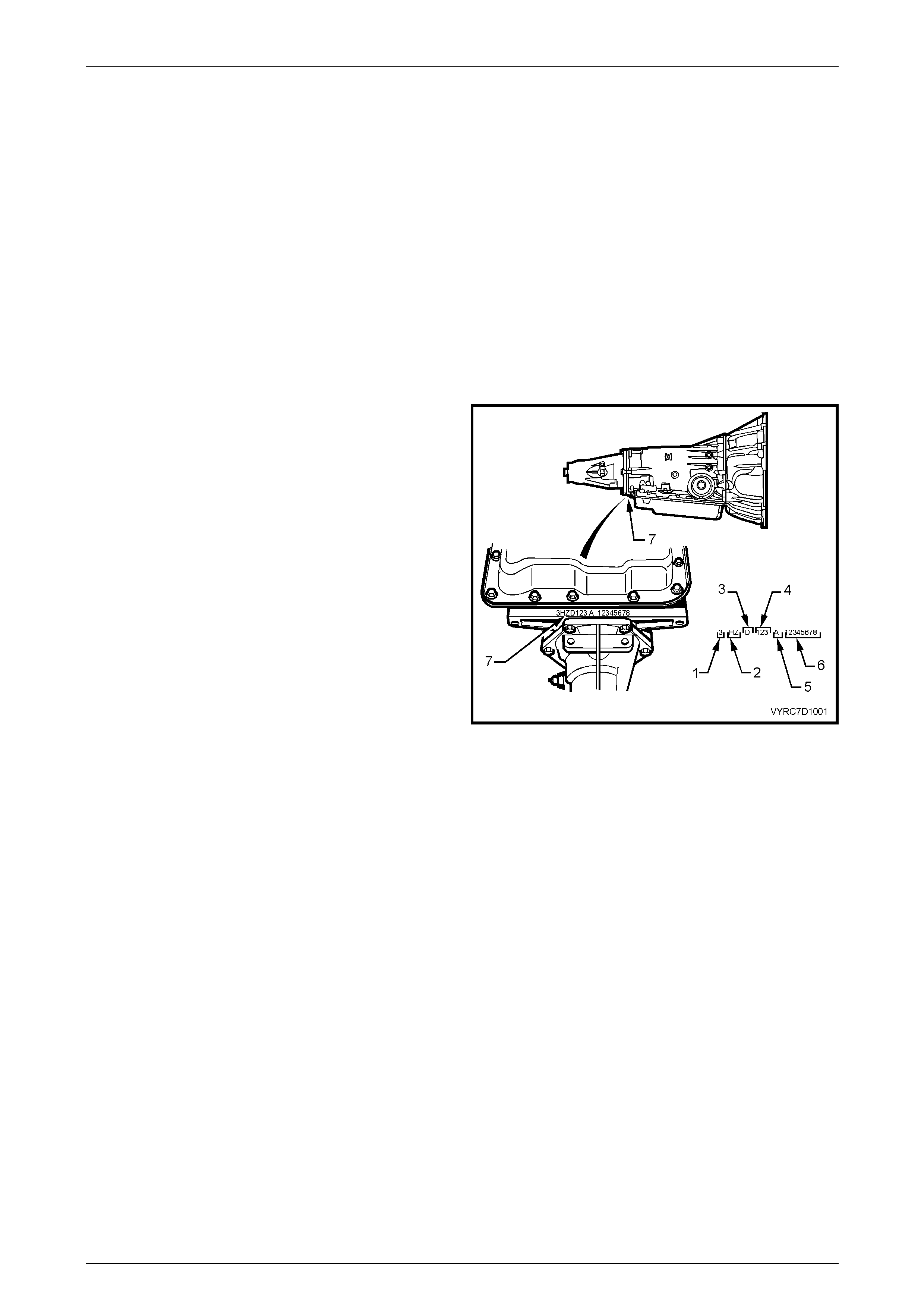
The Hydra-Matic 4L65E four speed automatic transmission
as fitted to MY2003 VY Series Cab Chassis Models has an
identification prefix of ‘HZDR’. The identification can be
determined from a stamping located on the rear underside
facing of the main transmission housing, just behind the oil
pan. Refer to Figure 7D-1
1 3 = 2003
2 Model = HZ
3 Hydra-Matic 4L65-E = DR
4 Julian Date (Day of Year)
5 Shift Built
a. First Shift = A, B, J
b. Second Shift = C, H, W
6 Serial Number
7 Transmission Identification location Figure 7D-1
Transmission Components
The Hydra-Matic 4L65-E four speed automatic transmission as fitted to MY2003 VY Series Cab Chassis Models utilises
the same components as the 4L60E, HAD automatic transmission as fitted to MY2003 VY and V2 Series Models with the
exception to the following components.
1 The input carrier is up-graded to a new five-pinion construction to cater for high torque and load demands.
2 The sun reaction shell thrust washer is up-graded to a new thrust needle bearing construction to cater for high
torque and load demands.
3 The reaction carrier is up-graded to a new five-pinion construction to cater for high torque and load demands.
4 The addition of an oil deflector for the five pinion reaction carrier.
5 A new output-shaft sleave and output shaft seal to cater for the new five-pinion carrier.
6 A new O-Ring seal for the turbine shaft.
7 A new Input housing and shaft assembly to cater for high torque and load demands.
8 A quantity increase of the fibre clutch plates used in the third and fourth clutch plate assembly.
9 A quantity increase of the steel clutch plates used in the third and fourth clutch plate assembly.
10 New select fit third and fourth clutch backing plate to cater for the increased quantity of third and fourth clutch fibre
and steel clutch plates.
11 New control valve body gasket and spacer plate that has the identification marking of ‘VB IPU CA’.