Fuel Tank Page 8A1–1
Page 8A1–1
Section 8A1
Fuel Tank
ATTENTION
Before performing any service operation or other procedure described in this Section, refer to Section 00
Warnings, Cautions and Notes for correct workshop practices w ith regard to safety and/or property damage.
1 General Information............................................................................................................................... 3
1.1 Modular Fuel Pump and Sender Assembly..........................................................................................................6
Single Turbine Fuel Pump.....................................................................................................................................6
Functional Description of Modular Fuel Pump and Sender Assembly .............................................................7
V6 Engine...........................................................................................................................................................7
GEN III V8 Engine..............................................................................................................................................7
Single Line Fuel Delivery System .........................................................................................................................8
V6 Engine...........................................................................................................................................................8
GEN III V8 Engine..............................................................................................................................................8
Pressure Regulator................................................................................................................................................9
Fuel Level Sender Assembly.................................................................................................................................9
Rollover Valve.........................................................................................................................................................9
1.2 System Components............................................................................................................................................10
V6 Engine..............................................................................................................................................................10
GEN III V8 Engine.................................................................................................................................................12
2 Service Operations.............................................................................................................................. 14
2.1 Fuel Tank ..............................................................................................................................................................14
Remove .................................................................................................................................................................14
Reinstall................................................................................................................................................................16
2.2 Fuel Tank Support Straps....................................................................................................................................17
Remove .................................................................................................................................................................17
Reinstall................................................................................................................................................................17
2.3 Support Bracket ...................................................................................................................................................18
Remove .................................................................................................................................................................18
Reinstall................................................................................................................................................................19
2.4 Modular Fuel Pump and Sender Assembly — V6..............................................................................................20
Remove .................................................................................................................................................................20
Test........................................................................................................................................................................22
Fuel Level Sender ............................................................................................................................................22
Disassemble.........................................................................................................................................................23
Reassemble..........................................................................................................................................................29
Reinstall................................................................................................................................................................29
2.5 Modular Fuel Pump and Sender Assembly — GEN III V8.................................................................................31
Remove .................................................................................................................................................................31
Test........................................................................................................................................................................34
Fuel Level Sender ............................................................................................................................................34
Disassemble.........................................................................................................................................................34
Reassemble..........................................................................................................................................................40
Reinstall................................................................................................................................................................40
2.6 Fuel Filter Assembly............................................................................................................................................42
Remove .................................................................................................................................................................42
Reinstall................................................................................................................................................................42
2.7 Fuel Level Sender Assembly...............................................................................................................................43
Disassemble.........................................................................................................................................................43
Reassemble..........................................................................................................................................................48
Techline
Techline

Fuel Tank Page 8A1–2
Page 8A1–2
2.8 Pressure Regulator..............................................................................................................................................49
V6 Engine..............................................................................................................................................................49
Remove............................................................................................................................................................49
Reinstall............................................................................................................................................................49
GEN III V8 Engine.................................................................................................................................................50
Remove............................................................................................................................................................50
Reinstall............................................................................................................................................................50
2.9 Suction Filter........................................................................................................................................................51
Remove .................................................................................................................................................................51
Reinstall................................................................................................................................................................51
2.10 Modular Fuel Pump..............................................................................................................................................52
Remove .................................................................................................................................................................52
Reinstall................................................................................................................................................................53
2.11 Rollover Valve.......................................................................................................................................................54
2.12 Fuel Pipe Arrangement........................................................................................................................................55
V6 Engine..............................................................................................................................................................55
GEN III V8 Engine.................................................................................................................................................57
3 Specifications....................................................................................................................................... 60
4 Torque Wrench Specifications........................................................................................................... 61
5 Special Tools........................................................................................................................................ 62

Fuel Tank Page 8A1–3
Page 8A1–3
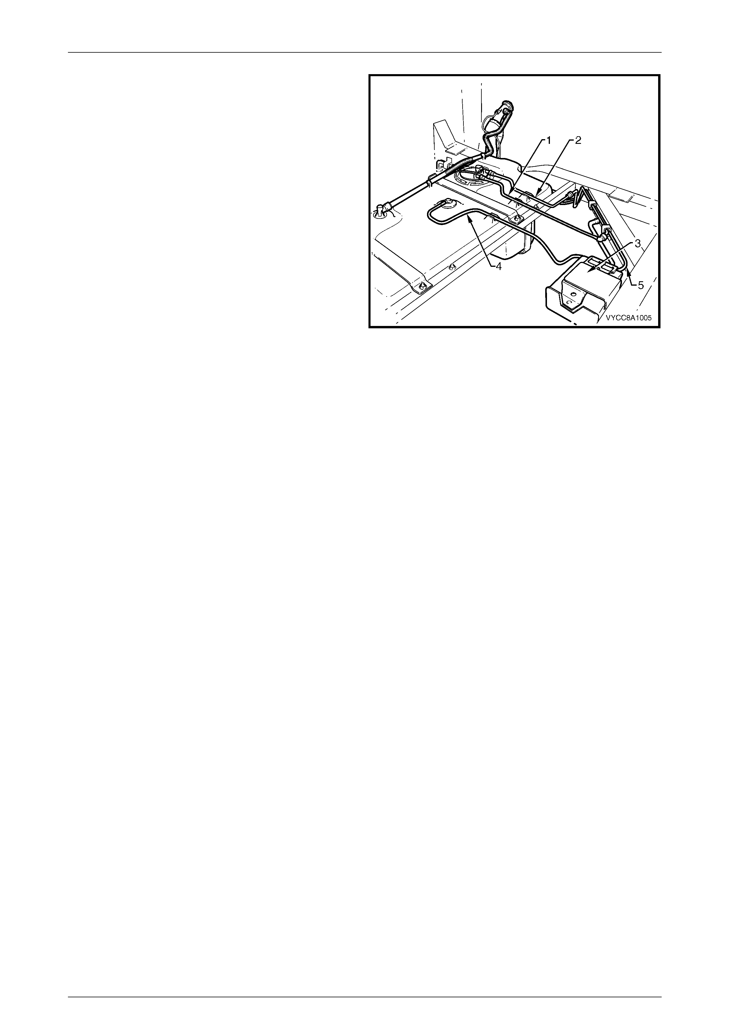
1 General Information
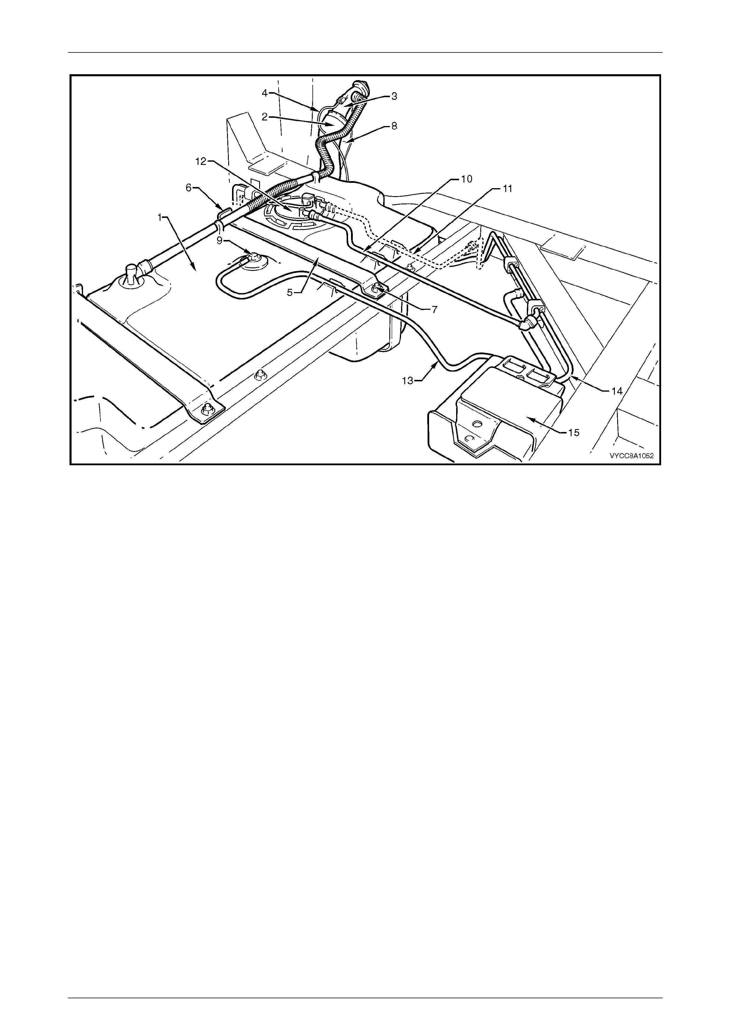
The 68.5-litre fuel tank (1) fitted to MY 2003 VY Series Regular Cab vehicles is a 'W'-type high-density multi-layer
polyethylene construction with a separate fuel filler neck, refer to Figure 8A1 – 1. The fuel filler neck consists of a
flexible rubber centre section (2) with hose clamps either end and a steel upper pipe (3) that incorporates the filler neck
vent fitting and counter-syphon mechanism, and an earthing wire (4). The fuel tank is fitted on a removable frame
underneath the load floor front panel assembly. The fuel tank is retained by two steel mounting straps (5) that fit into
keyed steel risers (6) welded to the forward chassis crossmember. Both steel mounting straps are anchored with a nut
and spring washer to studs (7) welded to the rear chassis crossmember.
The fuel filler neck is fixed to a support bracket (8) bolted to the chassis. The fuel tank is not repairable and, if
damaged, must be replaced. A rollover valve (9) is fitted directly into the top of the fuel tank, but is not serviceable.
Refer to 2.2 Fuel Tank Support Straps for information on the removable frame underneath the fuel tank.
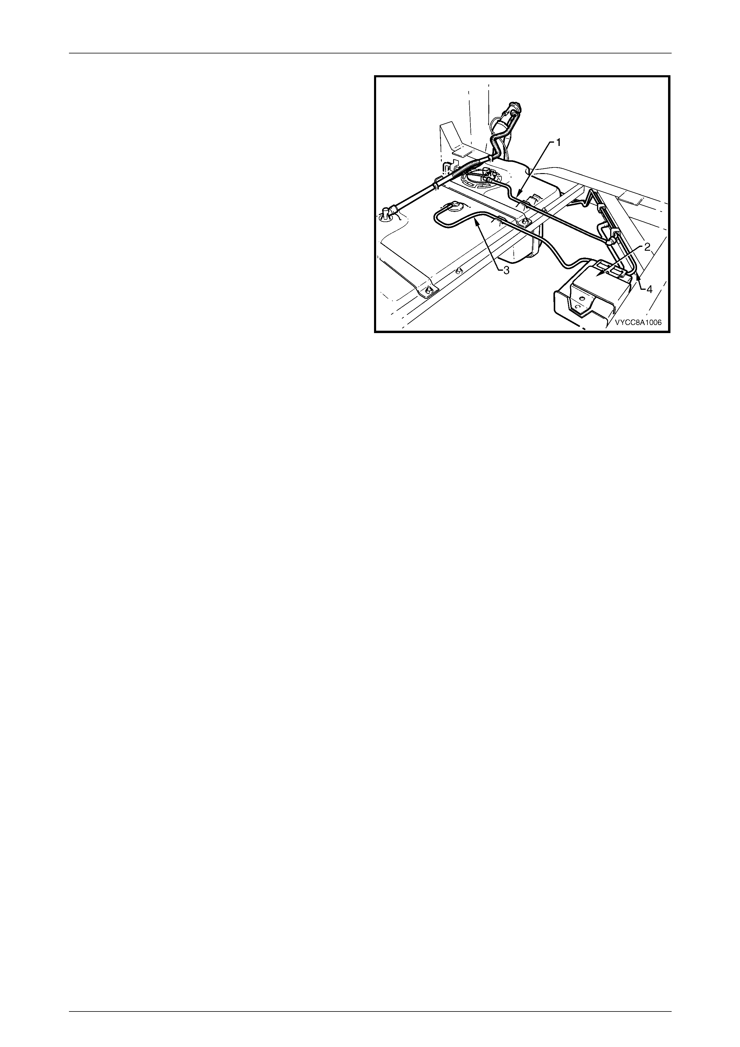
Quick-connect fittings are used on the fuel feed (10) and fuel return lines (11) at both the modular fuel pump and sender
assembly (12) and engine ends. Quick-connect fittings are also used on the fuel tank vent line (13) and the fuel vapour
canister purge line (14) at the fuel vapour canister (15).
For vehicles fitted with the GEN III V8 engine, the modular fuel pump and sender assembly also incorporates a pressure
regulator; the pressure regulator on vehicles fitted with the V6 engine is located on the fuel rail in the engine bay.
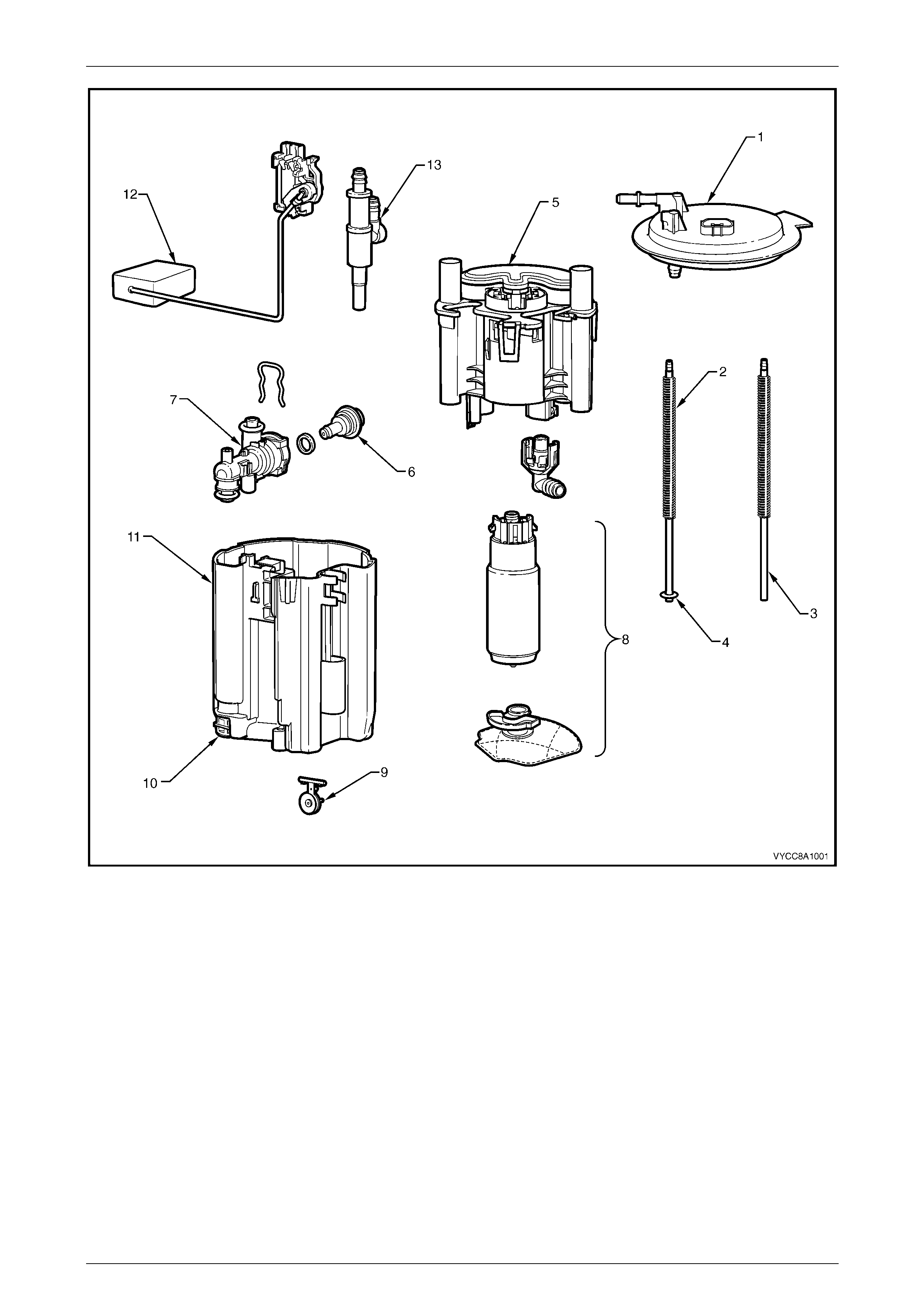
The in-tank, modular fuel pump and sender assembly includes a fuel pump and suction filter assembly, pressure
regulator holder (7), pressure regulator (6 — GEN III V8 only), reservoir (11), fuel level sender assembly (12), reservoir
jet pump (10) and cover (1), refer to Figure 8A1 – 2.
Servicing details for these and other fuel tank and fuel line related items are covered in this Section.
Both the fuel pump and suction filter assembly, and the fuel level sender assembly are serviceable items. For service
intervals of these items, refer to Section 0B Lubrication and Service.
NOTE
Figure 8A1 – 1 is a generic illustration for V6 and
GEN III V8 vehicles.
Fuel Tank Page 8A1–4
Page 8A1–4
Figure 8A1 – 1
Legend
1 Fuel Tank
2 Fuel Filler Neck Flexible
Rubber Centre Sec t i on
3 Fuel Filler Neck S t eel Upper
Pipe
4 Earthing Wire
5 Fuel Tank Mounting S trap
(2 places)
6 Fuel Tank Mounting S trap Front
Anchoring P oi nt
7 Stud (2 places)
8 Fuel Inlet S upport Brack et
9 Rollover Valve
10 Fuel Feed Line
11 Fuel Return Line
(V6 Vehic l es Only)
12 Modular Fuel Pum p and
Sender Assembl y
13 Fuel Tank Vent Li ne
14 Fuel Vapour Canis t er Purge Line
15 Fuel Vapour Canister
Fuel Tank Page 8A1–5
Page 8A1–5
Figure 8A1 – 2
Legend
1 Modular Fuel Pump and Sender
Assembly Cover
2 Spring (2 places)
3 Shaft (2 pl aces)
4 Circlip
5 Fuel Filter Assembly
6 Pressure Regulator
(GEN III V8 Only)
7 Pressure Regulator Holder
8 Fuel Pump and Suct i on Fi lter Ass embly
9 Flapper Valve
10 Reservoir Jet Pump
11 Reservoir
12 Fuel Level Sender Assembly
13 Transfer J et Pump
For additional information regarding the pressure regulator and fuel system electrical diagnostic procedures not
contained in this Section refer to:
• Section 6C1 Powertrain — V6 Engine, and
• Section 6C3 Powertrain — GEN III V8 Engine.
Fuel Tank Page 8A1–6
Page 8A1–6
1.1 Modular Fuel Pump and Sender
Assembly
The modular fuel pump and sender assembly maintains an optimum fuel level in the reservoir. This ensures a
continuous fuel flow under all fuel level conditions and vehicle attitudes. The modular fuel pump and sender assembly
also provides an accurate means of measuring the fuel level within the fuel tank.
Single Turbine Fuel Pump
Figure 8A1 – 3 details fuel flow through the single turbine fuel pump used with the V6 and GEN III V8 engines.
Figure 8A1 – 3
Legend
A Fuel
B Vapour Out 1 Fuel Pump End Cap
2 Impeller
3 Fuel Pump Body
4 Fuel Pump Outlet O-ri ng Coll ar
Fuel Tank Page 8A1–7
Page 8A1–7
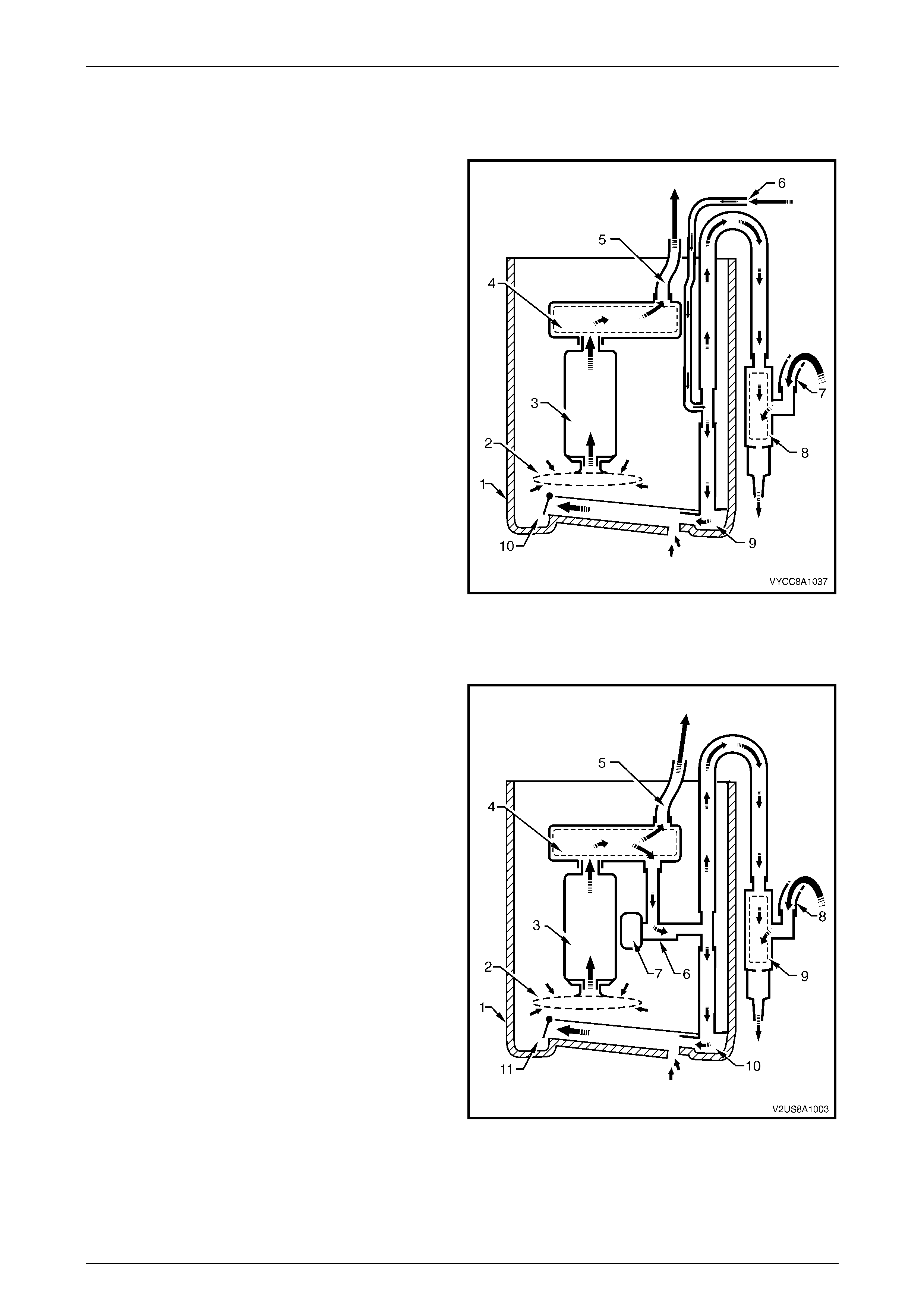
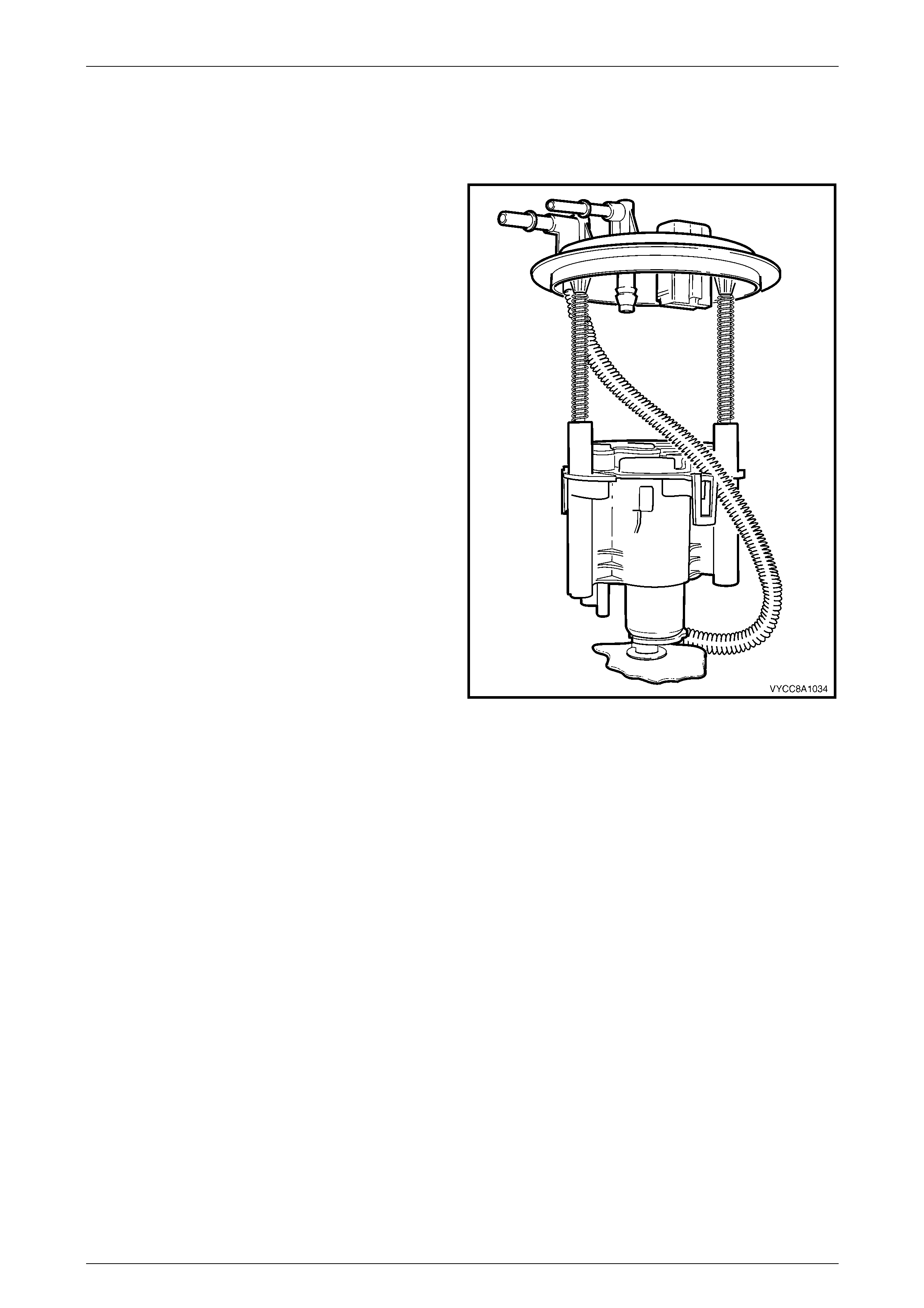
Functional Descri pt i on of Modular Fuel Pump and Sender Assembly
V6 Engine
Fuel is pumped from the fuel tank to the engine via an
internal pump in the modular fuel pump and sender
assembly.
Fuel in the reservoir (1) is drawn through the suction
filter (2) and fuel pump (3), driven by a constant-speed
motor. Fuel flows under pressure through the fuel filter
assembly (4) and flex pipe (5), exits the modular fuel pump
and sender assembly through the fuel feed port on the
modular fuel pump and sender assembly cover, then
through fuel lines into the engine.
When the engine is operating, fuel returning via the fuel
return line (6) mixes with fuel drawn from the other side of
the fuel tank baffle via the low fuel level fuel feed pipe (7),
then through the transfer jet pump (8). Returned fuel also
flows through the reservoir jet pump (9) and valve (10) into
the reservoir. This flow ensures the reservoir is always full
of fuel; the valve prevents fuel from exiting the reservoir
when the engine is turned off.
At high fuel levels, the modular fuel pump and sender
assembly is immersed in fuel. At low fuel levels, the fuel
level is to the top of the reservoir.
Electrical power is supplied to the fuel pump by an integral
connector on the modular fuel pump and sender assembly
cover. An internal harness assembly completes the
connection to the pump.
Figure 8A1 – 4
GEN III V8 Engine
Fuel is pumped from the fuel tank to the engine via an
internal pump in the modular fuel pump and sender
assembly.
Fuel in the reservoir (1) is drawn through the suction
filter (2) and fuel pump (3), driven by a constant-speed
motor. Fuel flows under pressure through the fuel filter
assembly (4) and flex pipe (5), exits the modular fuel pump
and sender assembly through the fuel feed port on the
modular fuel pump and sender assembly cover, then
through fuel lines into the engine.
When the engine is operating, fuel flows through the
pressure regulator holder (6); if fuel pressure increases, the
pressure regulator (7) limits the fuel flow. Fuel is drawn
from the other side of the fuel tank baffle via the low fuel
level fuel feed pipe (8), then through the transfer jet
pump (9). Fuel from the pressure regulator holder also
flows through the reservoir jet pump (10) and valve (11) into
the reservoir. This flow ensures the reservoir is always full
of fuel; the valve prevents fuel from exiting the reservoir
when the engine is turned off.
At high fuel levels, the modular fuel pump and sender
assembly is immersed in fuel. At low fuel levels, the fuel
level is to the top of the reservoir.
Electrical power is supplied to the fuel pump by an integral
connector on the modular fuel pump and sender assembly
cover. An internal harness assembly completes the
connection to the pump.
Figure 8A1 – 5
Fuel Tank Page 8A1–8
Page 8A1–8
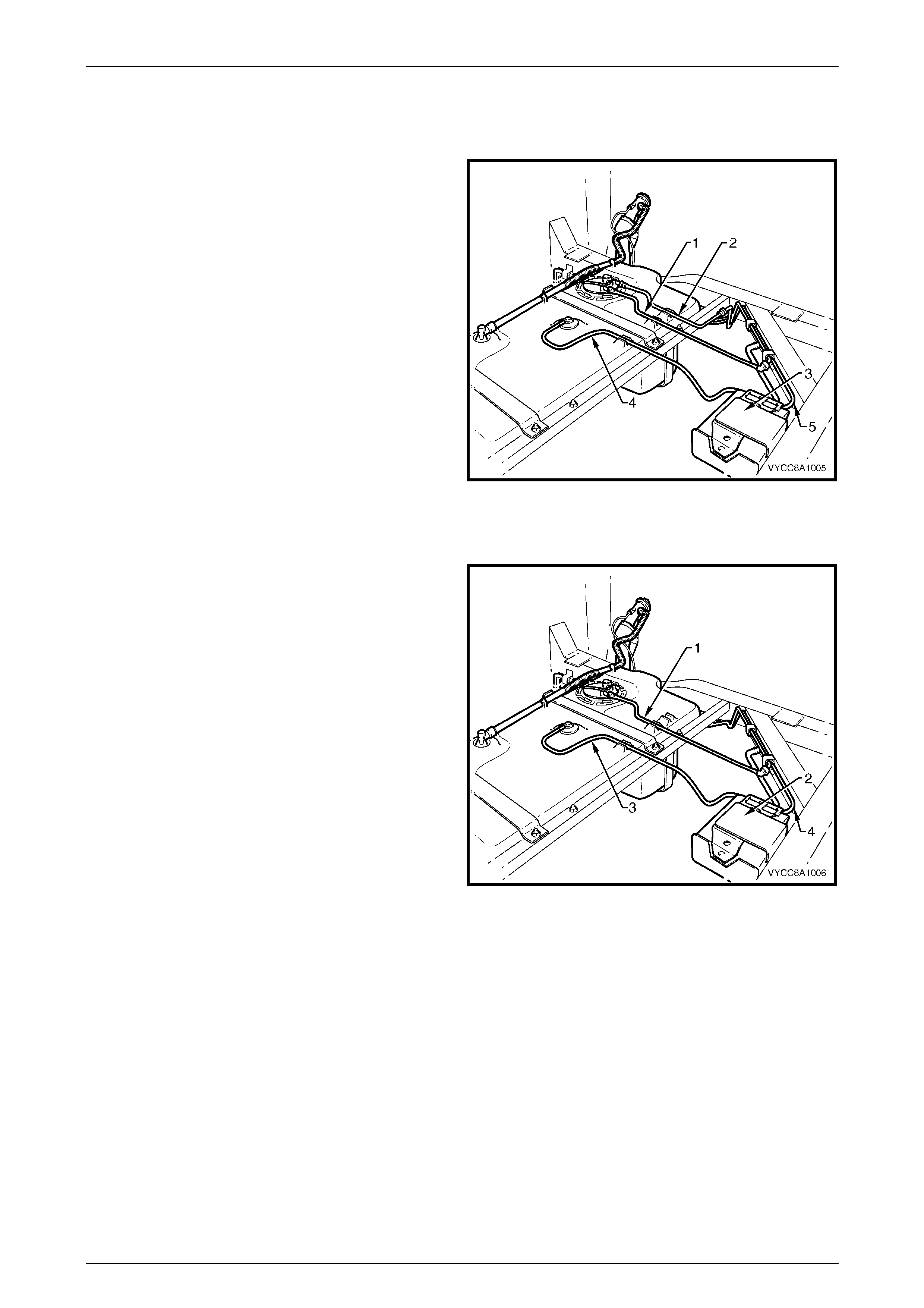
Single Line Fuel Delivery System
V6 Engine
Fuel is directed from the modular fuel pump and sender
assembly, then through the flexible fuel feed line (1) and on
to the engine bay and fuel rail.
When fuel line pressure exceeds the pre-determined value
of 400 kPa (+/–3 kPa), the pressure regulator attached to
the fuel rail opens, allowing excess fuel at system pressure
to return to the fuel tank via the fuel return line (2). This
process occurs continuously while the pump is operating.
A three-port fuel vapour canister (3) is mounted in a bracket
on a chassis crossmember behind the fuel tank. The fuel
vapour canister stores fuel tank vapour via the fuel tank
vent line (4) and releases it to the fuel vapour canister
purge line (5).
Figure 8A1 – 6
GEN III V8 Engine
Fuel is directed from the modular fuel pump and sender
assembly, then through the flexible fuel feed line (1) and on
to the engine bay and fuel rail.
When fuel line pressure exceeds the pre-determined value
of 400 kPa (+/–3 kPa), the pressure regulator in the
modular fuel pump and sender assembly opens, allowing
excess fuel at system pressure to return to the modular fuel
pump and sender assembly via the reservoir jet pump. This
process occurs continuously while the pump is operating.
A three-port fuel vapour canister (2) is mounted in a bracket
on a chassis crossmember behind the fuel tank. The fuel
vapour canister stores fuel tank vapour via the fuel tank
vent line (3) and releases it to the fuel vapour canister
purge line (4).
Figure 8A1 – 7
Fuel Tank Page 8A1–9
Page 8A1–9
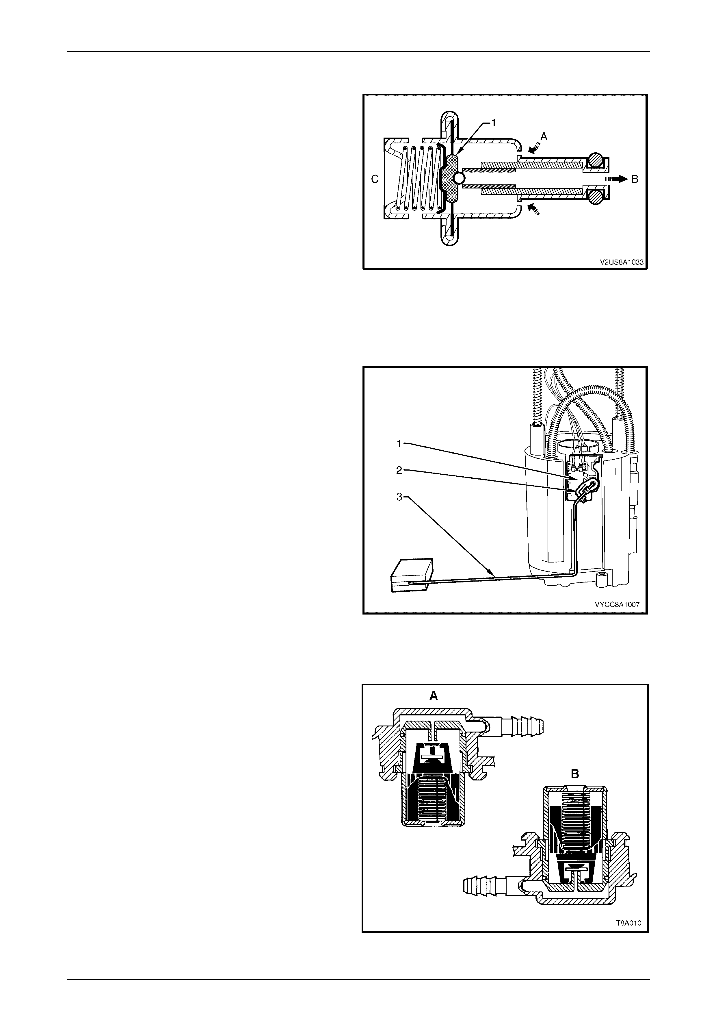
Pressure Regulator
The pressure regulator is a diaphragm-operated relief valve.
On vehicles fitted with the V6 engine, the pressure regulator
is fitted to the engine fuel rail; on vehicles fitted with the
GEN III V8 engine it is in the modular fuel pump and sender
assembly reservoir. The pressure regulator maintains a
controlled pressure at the injectors at all times by regulating
fuel flow into the fuel feed line.
Fuel flows from the fuel pump, through the fuel filter
assembly and exits into the fuel feed line or pressure
regulator entry port (A). When pressure builds in the fuel
feed line, the diaphragm and valve (1) is progressively
pushed out, allowing fuel to exit through the port (B). The
valve is normally closed by mechanical spring pressure (C).
Fuel exiting the pressure regulator is directed into the
transfer and reservoir jet pumps to provide continuous fuel
circulation.
Figure 8A1 – 8
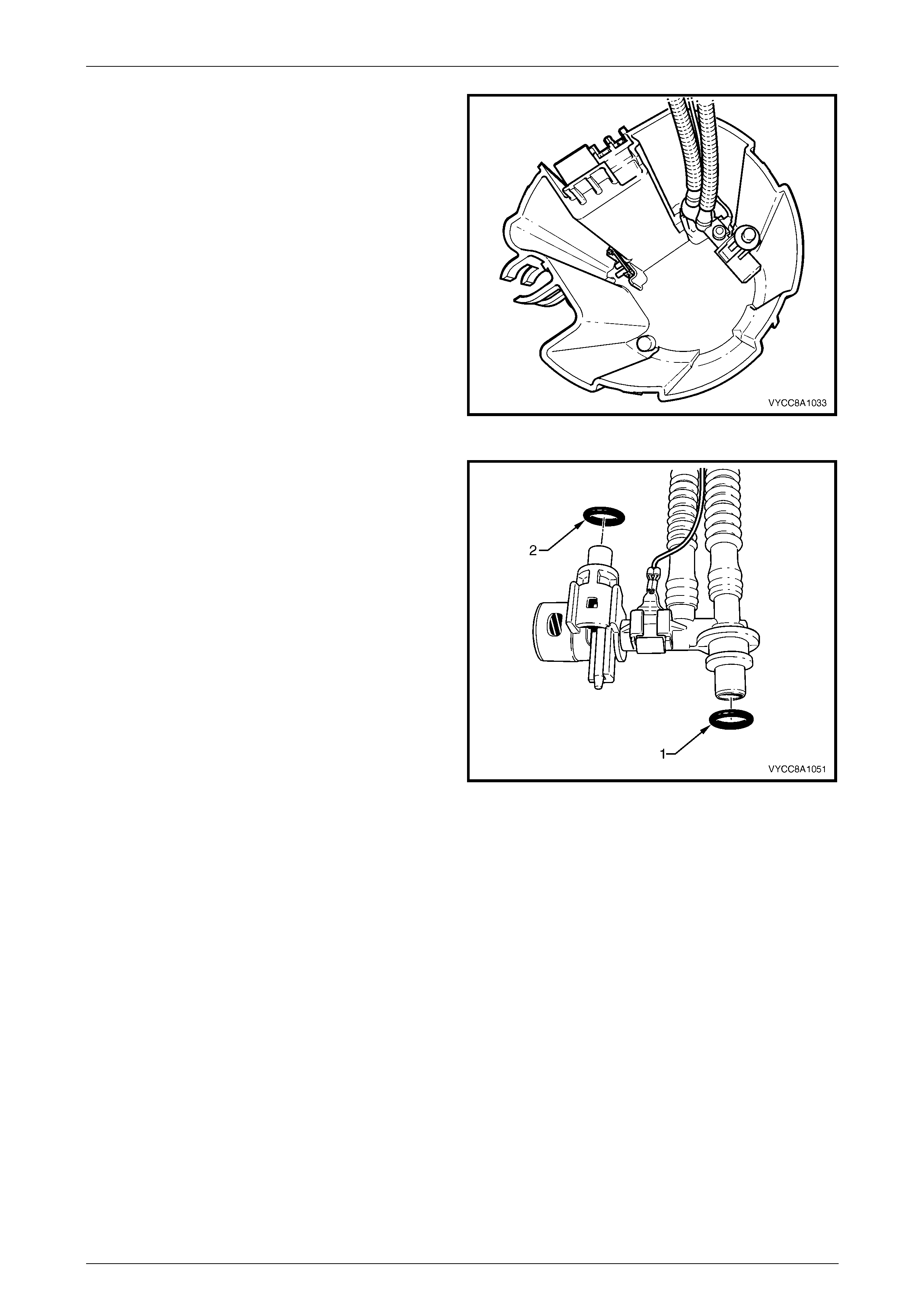
Fuel Level Sender Assembly
The fuel level sender assembly consists of a variable
resistor card holder (1), detachable nylon wiper piece (2)
and a fuel level sender float and arm (3). These
components convert the fuel level in the fuel tank into a
variable electrical signal that provides the fuel level
information on the fuel gauge in the instrument panel.
The fuel level sender assembly mounting is part of the
reservoir moulding. Two wires connect the variable resistor
card to the modular fuel pump and sender assembly wiring
harness.
The variable resistor card varies the resistance, dependent
upon the position of the fuel level sender float and arm and
sends that signal via hard wire to the instrument cluster.
This resistance signal changes relative to the wiper contact
position on the conductive bars of the resistor card.
Figure 8A1 – 9
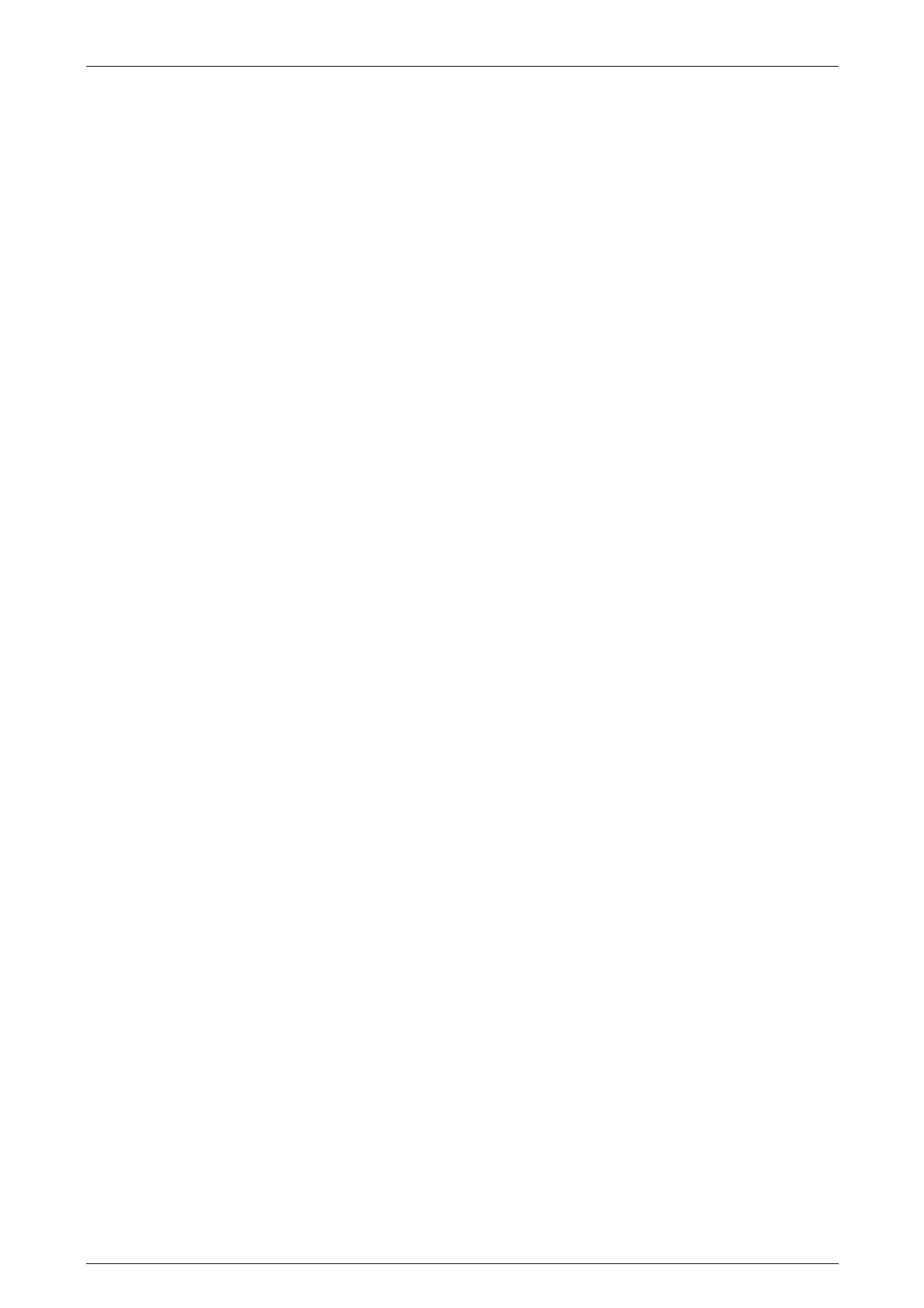
Rollover Valve
The fuel tank incorporates a rollover valve. The rollover
valve limits vapour venting to the fuel vapour canister using
a fixed-sized orifice that is normally open (View A). If the
vehicle rolls over (View B), the fuel tank vent line to the fuel
vapour canister is safely shut off by the rollover valve,
preventing liquid fuel from flooding the fuel vapour canister.
NOTE
The rollover valve is fitted directly onto the tank
and is not serviceable separately. If it is faulty,
the tank (with a new rollover valve fitted) must
be replaced.
Figure 8A1 – 10
Fuel Tank Page 8A1–10
Page 8A1–10
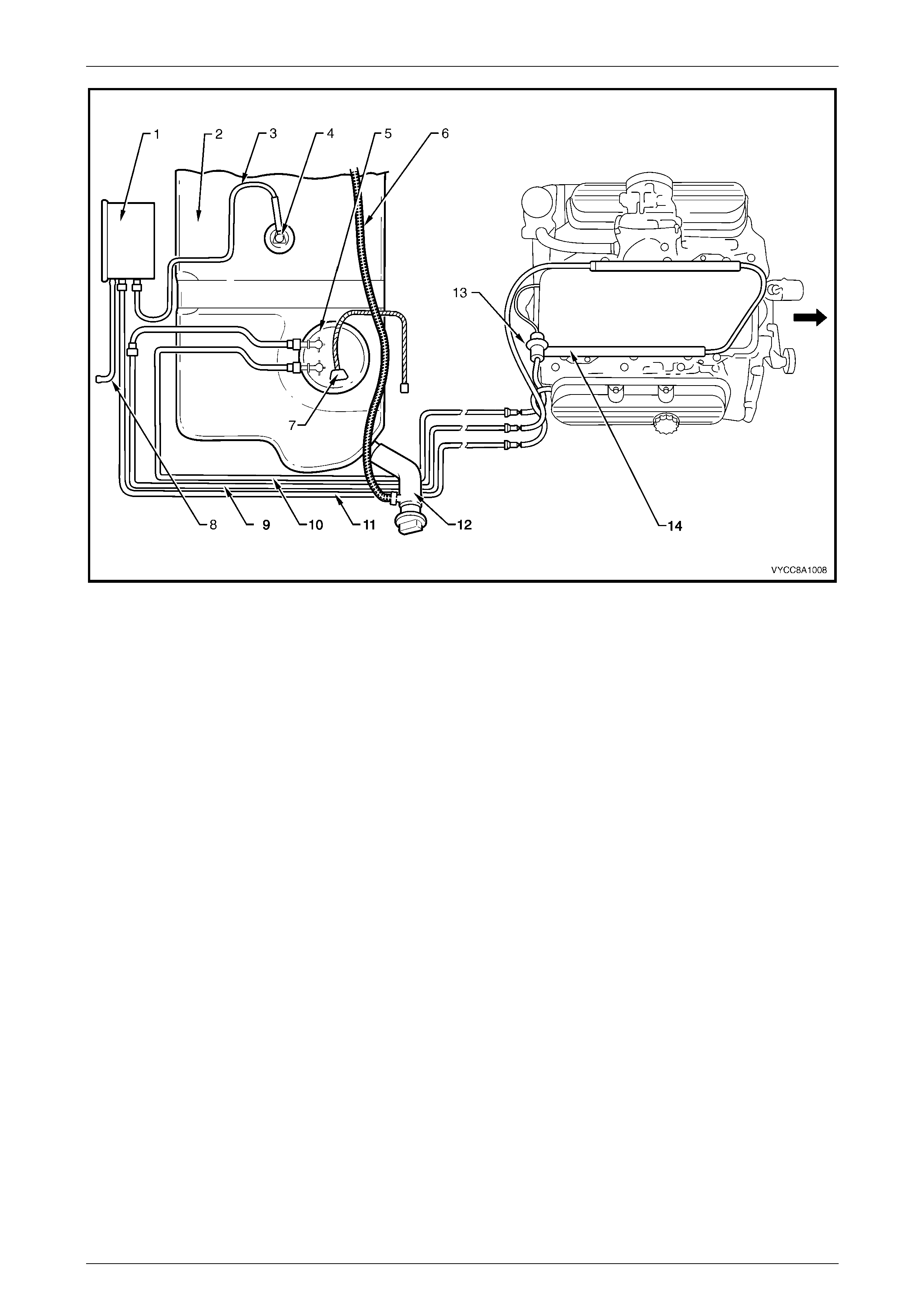
1.2 System Components
V6 Engine
The pressure regulator on vehicles fitted with the V6 engine is located on the fuel rail in the engine bay. Vehicles fitted
with the V6 engine have a fuel return line from the pressure regulator that passes through the modular fuel pump and
sender assembly cover. The fuel control system consists of the following components, refer to Figure 8A1 – 11 for the
V6 engine:
• fuel vapour canister (1);
• fuel tank (2);
• fuel tank vent line (3);
• rollover valve (4);
• modular fuel pump and sender assembly (5), consisting of:
• modular fuel pump and sender assembly cover,
• sleeve rods and retaining springs,
• reservoir,
• fuel pump and suction filter assembly,
• fuel level sender assembly,
• reservoir jet pump (integral with reservoir),
• valve and cap,
• transfer jet pump,
• fuel pipes, and
• wiring harness and connectors;
• inlet breather pipe (6);
• modular fuel pump and sender assembly harness connector (7);
• fuel vapour overload breather pipe (8);
• fuel feed line (9);
• fuel return line (10);
• fuel vapour canister purge line (11);
• fuel filler neck (12);
• pressure regulator (13);
• fuel rail (14);
• power train control module (PCM);
• fuel pump relay; and
• injectors.
Fuel Tank Page 8A1–11
Page 8A1–11
Figure 8A1 – 11
Legend
1 Fuel Vapour Canis ter
2 Fuel Tank
3 Fuel Tank Vent Line
4 Rollover Valve
5 Modular Fuel Pump and Sender
Assembly
6 Inlet B reather Pipe
7 Modular Fuel Pump and Sender
Ass embly Harnes s Connector
8 Fuel Vapour Overload B reather Pipe
9 Fuel Feed Line
10 Fuel Return Line
11 Fuel Vapour Canis t er Purge Line
12 Fuel Filler Neck
13 Pressure Regulator
14 Fuel Rail

Fuel Tank Page 8A1–12
Page 8A1–12
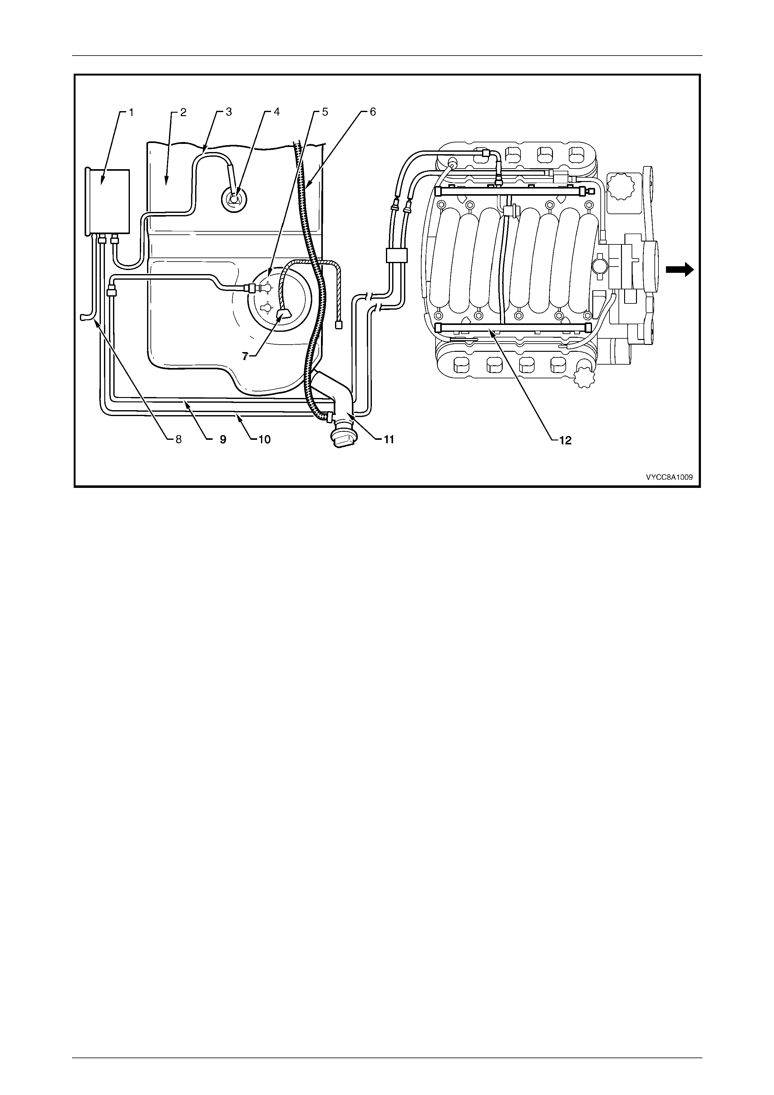
GEN III V8 Engine
The pressure regulator on vehicles fitted with the GEN III V8 engine is located in the modular fuel pump and sender
assembly. The fuel return line port on the modular fuel pump and sender assembly cover on vehicles fitted with the
GEN III V8 engine is plugged. The fuel control system consists of the followi ng components, refer to Figure 8A1 – 12 for
the GEN III V8 engine:
• fuel vapour canister (1);
• fuel tank (2);
• fuel tank vent line (3);
• rollover valve (4);
• modular fuel pump and sender assembly (5), consisting of:
• modular fuel pump and sender assembly cover,
• sleeve rods and retaining springs,
• reservoir,
• fuel pump and suction filter assembly,
• fuel level sender assembly,
• reservoir jet pump (integral with reservoir),
• valve and cap,
• transfer jet pump,
• pressure regulator,
• fuel pipes, and
• wiring harness and connectors;
• inlet breather pipe (6)
• modular fuel pump and sender assembly harness connector (7);
• fuel vapour overload breather pipe (8);
• fuel feed line (9);
• fuel vapour canister purge line (10);
• fuel filler neck (11);
• fuel rail (12);
• power train control module (PCM);
• fuel pump relay; and
• injectors.
Fuel Tank Page 8A1–13
Page 8A1–13
Figure 8A1 – 12
Legend
1 Fuel Vapour Canis ter
2 Fuel Tank
3 Fuel Tank Vent Line
4 Rollover Valve
5 Modular Fuel Pump and Sender
Assembly
6 Inlet B reather Pipe
7 Modular Fuel Pump and Sender
Ass embly Harnes s Connector
8 Fuel Vapour Overload B reather Pipe
9 Fuel Feed Line
10 Fuel Vapour Canis t er Purge Line
11 Fuel Filler Neck
12 Fuel Rail
Fuel Tank Page 8A1–14
Page 8A1–14
2 Service Operations
2.1 Fuel Tank
Remove
A depressurised fuel system contains fuel in
the fuel filter and fuel lines that can be spilled
during service operations.
Fuel vapour remains in the fuel tank even
when completely empty. Seal all openings in
the fuel tank using suitable material or a
plastic plug. Ensure no naked flames or other
ignition sources are nearby. Ensure all
mobile phones (and transmission devices
that may cause any metal objects to become
unintentional receiving antennas) are
switched off.
Wear safety glasses when using compressed
air. Do not blow compressed air onto any
body part.
1 Depressurise the fuel system, refer to:
• For V6 engine vehicles only, Section 6C1–3, 3.1 Fuel Pump Relay, or
• For GEN III V8 engine vehicles only, Section 6C3–3, 3.7 Fuel Pressure Relief Procedure.
2 Remove the fuel pump relay R16, refer to Section 12O, 1.4 Relays.
3 Remove the tray, refer to Section 1B1, Tray.
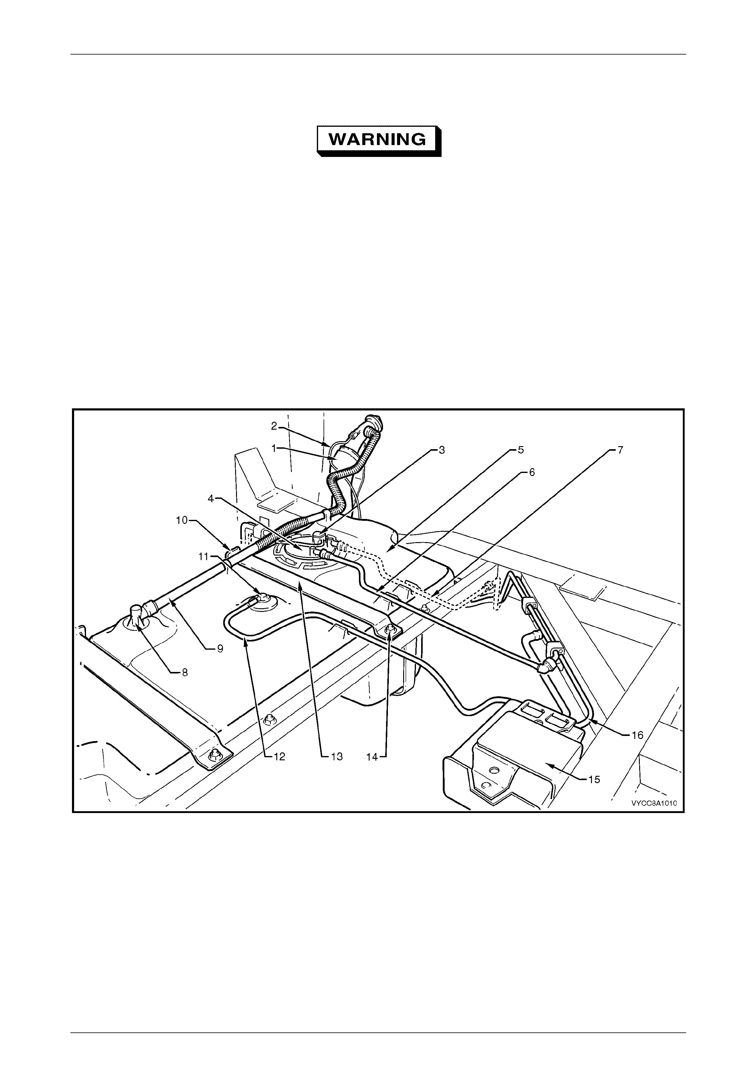
4 Use compressed air to ensure that all dirt and foreign materials are removed from all fuel connections before the
parts are disconnected, refer to Figure 8A1 – 13.
5 Disconnect the modular fuel pump and sender assembly harness connector (3), refer to Figure 8A1 – 13.
6 Tag, remove and cover the following items with a suitable material to prevent foreign objects from entering:
a the fuel feed line (6),
b for V6 engine vehicles only, the fuel return line (7),
NOTE
For information on quick-connect fittings for
Regular Cab and Crew Cab vehicles, refer to
MY 2003 VY and V2 Series Service Information,
Section 8A1 Fuel Tank, 2.10 Quick-connect
Fittings.
c inlet breather pipe (9) from the vapour collector, and
d fuel tank vent line (12).
Fuel Tank Page 8A1–15
Page 8A1–15
7 Remove the modular fuel pump and sender assembly (4), refer to 2.4 Modular Fuel Pump and Sender
Assembly — V6 or 2.5 Modular Fuel Pump and Sender Assembly — GEN III V8.
Ensure fuel is pumped or syphoned from both
sides of the baffle in the fuel tank.
8 Drain the fuel tank by pumping or syphoning fuel through the hole in the fuel tank (from which the modular fuel
pump and sender assembly was removed) using commercially available equipment.
NOTE
A permanent floodgate restriction in the lower
fuel filler neck prevents the fuel tank from being
drained through the filler aperture.
NOTE
Figure 8A1 – 13 is a generic illustration for V6
and GEN III V8 vehicles.
Figure 8A1 – 13
Legend
1 Fuel Filler Neck
2 Earthing Wire
3 Modular Fuel Pump and Sender
Ass embly Harnes s Connector
4 Modular Fuel Pump and Sender
Assembly
5 Fuel Tank
6 Fuel Feed Line
7 Fuel Return Line
(V6 Vehic l es Only)
8 Vapour Collector
9 Inlet B reather Pipe
10 Fuel Tank Mounting Strap Front
Anchoring P oi nt
11 Rollover Valve
12 Fuel Tank Vent Li ne
13 Fuel Tank Mounting S t rap (2 pl aces)
14 Stud (2 plac es)
15 Fuel Vapour Canister
16 Fuel Vapour Canis t er Purge Line
Fuel Tank Page 8A1–16
Page 8A1–16
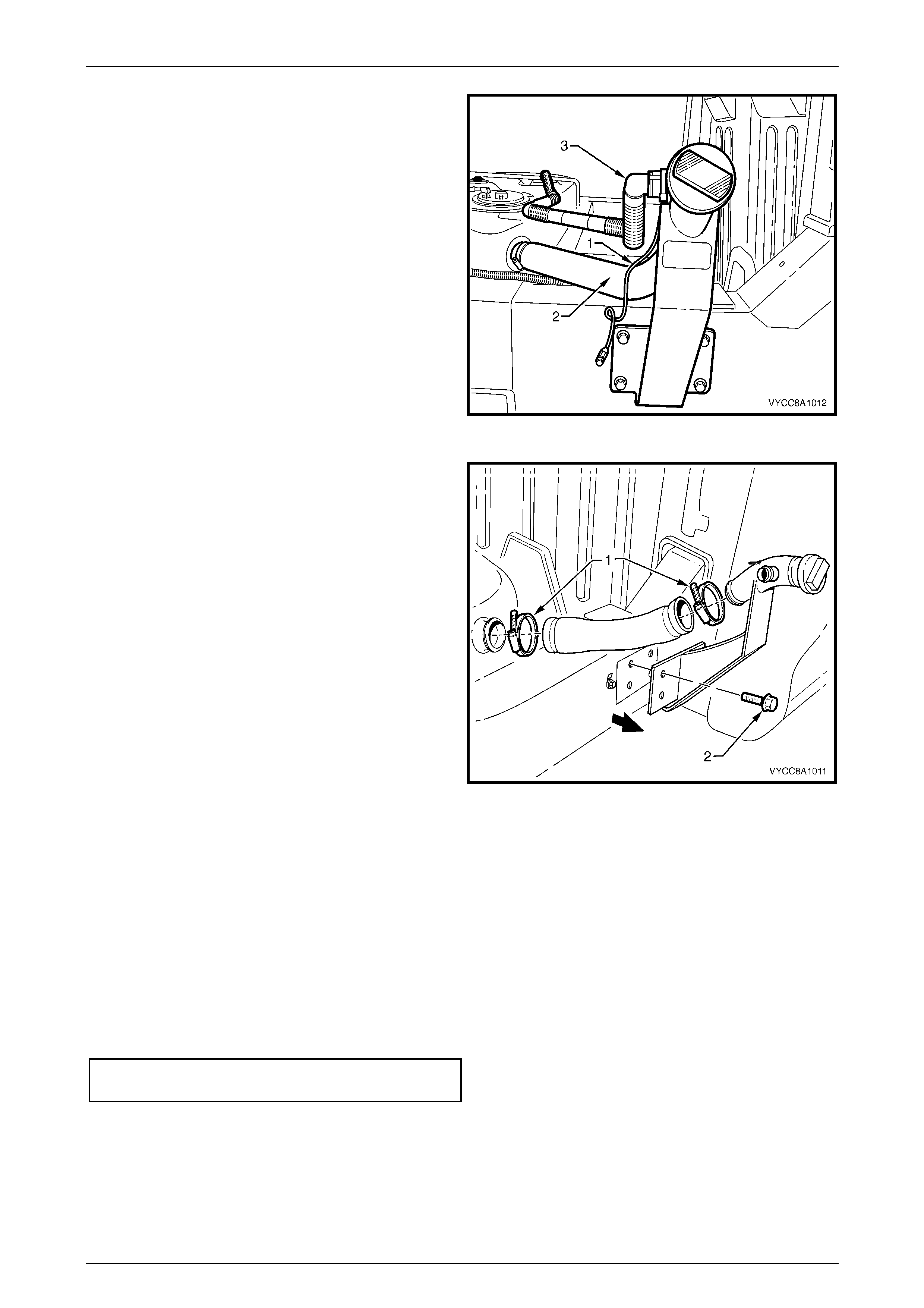
9 Remove the earthing wire (1) from the spade
connector on the fuel filler neck.
10 Remove the earthing wire from the spade connector
screw mounting on the chassis member.
11 Place the earthing wire in a safe location away from
the immediate worksite.
12 Loosen the screw clamp holding the flexible fuel inlet
pipe (2) onto the fuel filler neck.
13 Use compressed air to ensure that all dirt and foreign
materials are removed from the inlet breather pipe (3)
and fuel filler neck.
14 Remove the quick-connect fitting holding the inlet
breather pipe onto the fuel filler neck.
15 Cover the flexible fuel inlet pipe and inlet breather
pipe with a suitable material to prevent foreign objects
from entering.
Figure 8A1 – 14
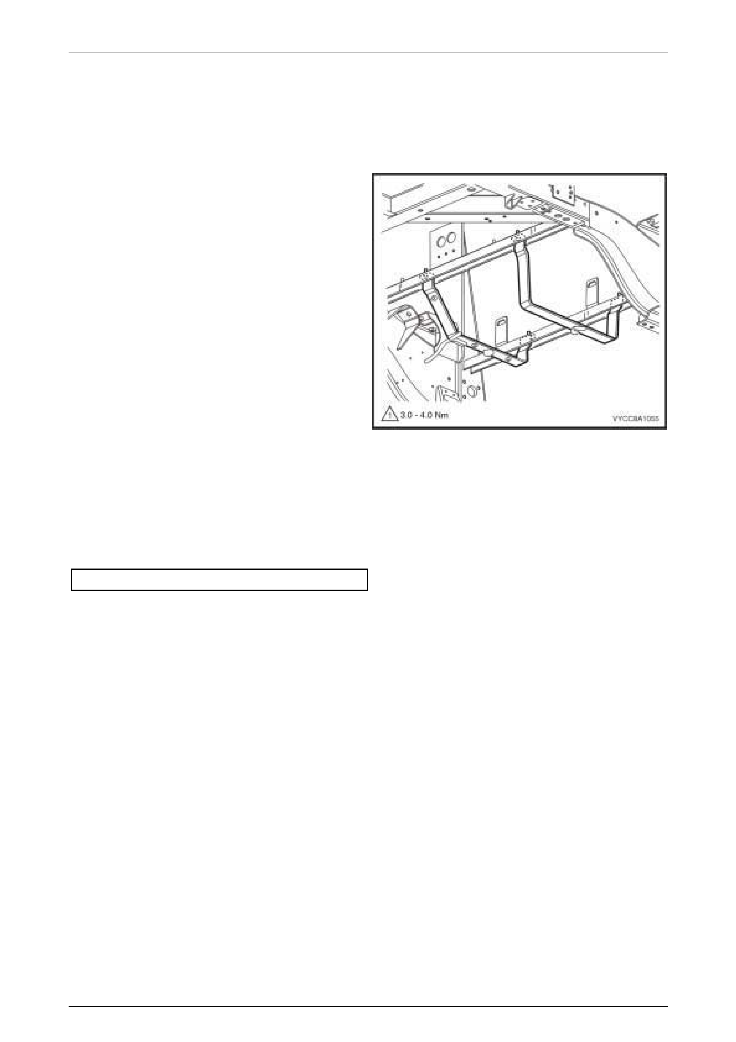
16 Loosen the screw clamps (1) from both ends of the
flexible fuel filler neck.
17 Remove the flexible fuel filler neck from the fuel tank
and support bracket.
18 Cover the flexible fuel filler neck with a suitable
material to prevent foreign objects from entering.
Figure 8A1 – 15
19 Remove the nuts from both fuel tank mounting strap studs (14).
20 Lift the fuel tank mounting straps away from the front anchoring points (10) and place in a safe location away from
the immediate worksite.
21 Remove the fuel tank from its support frame.
Reinstall
The installation procedure for the fuel tank is the reverse of the removal procedure, noting the following:
1 Ensure all parts are dust-free and clean before reinstalling.
2 Tighten both fuel tank mounting strap nuts to the correct torque specification.
Fuel tank mounting strap
nuts torque specification ........................20.0 – 25.0 Nm
Fuel Tank Page 8A1–17
Page 8A1–17
2.2 Fuel Tank Support Straps
Remove
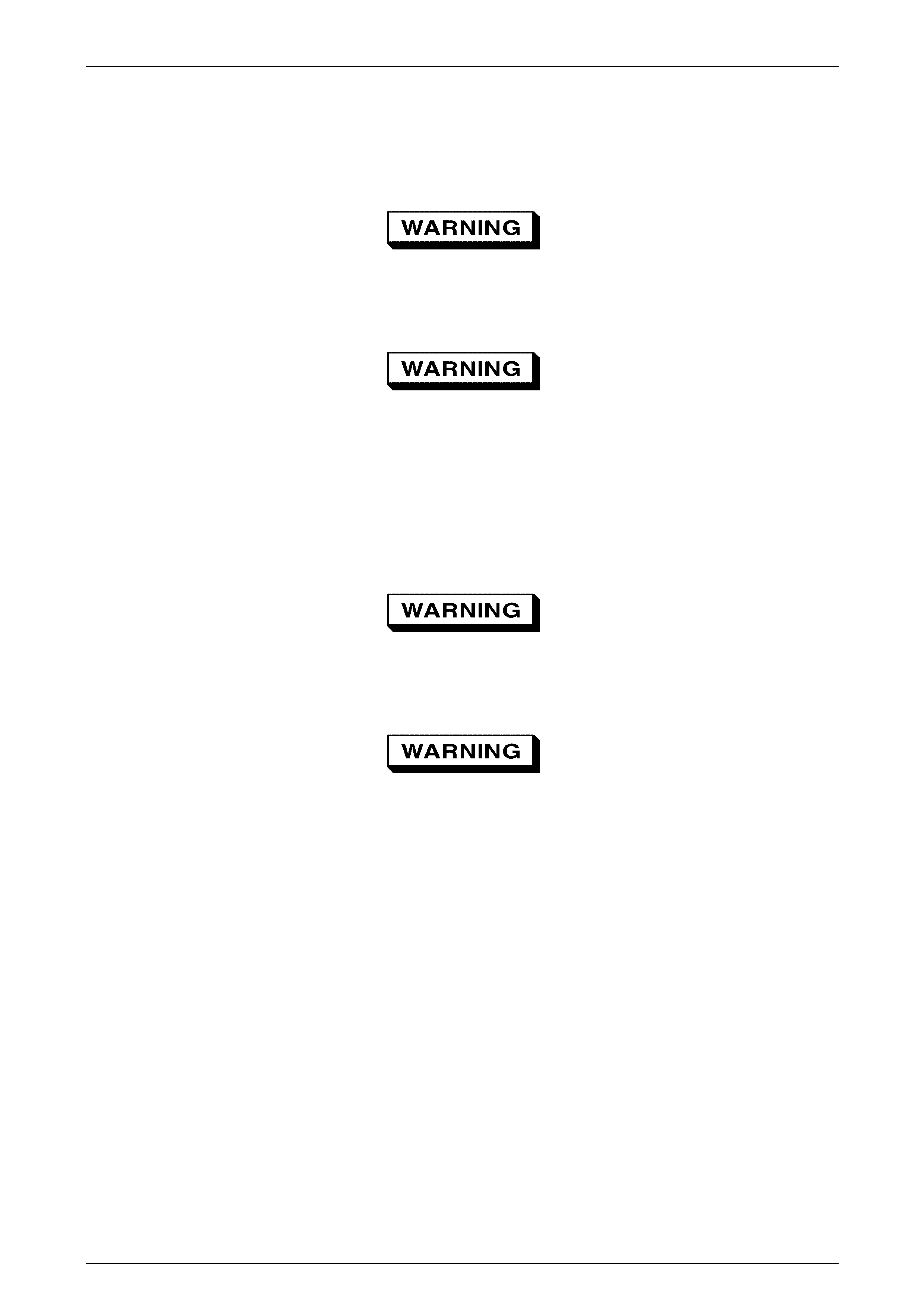
1 Remove the fuel tank, refer to 2.1 Fuel Tank.
2 Remove the rear park brake cable(s) from the fuel
tank support straps, refer to Section 5A Service and
Park Braking System.
3 Remove the intermediate muffler, refer to Section 8B
Exhaust System.
4 Remove the heat shield from the left fuel tank support
strap, refer to Section 8B Exhaust System.
5 Remove the fuel tank support straps and place the
nuts in a safe location away from the immediate
worksite.
Figure 8A1 – 16
Reinstall
The installation procedure is the reverse of the removal procedure, noting the following:
1 Ensure all parts are dust-free and clean before reinstalling.
2 Tighten the nuts that secure the fuel tank support straps to the correct torque specification.
Fuel Tank Support Straps......................30.0 – 40.0 Nm
Fuel Tank Page 8A1–18
Page 8A1–18
2.3 Support Bracket
Remove
A depressurised fuel system contains fuel in
the fuel filter and fuel lines that can be spilled
during service operations.
Fuel vapour remains in the fuel tank even
when completely empty. Seal all openings in
the fuel tank using suitable material or a
plastic plug. Ensure no naked flames or other
ignition sources are nearby. Ensure all
mobile phones (and transmission devices
that may cause any metal objects to become
unintentional receiving antennas) are
switched off.
Wear safety glasses when using compressed
air. Do not blow compressed air directly onto
any body part.
Ensure fuel is pumped or syphoned from both
sides of the baffle in the fuel tank.
1 Remove the modular fuel pump and sender assembly, refer to MY 2003 VY Series Service Information,
Section 8A1 Fuel Tank.
2 Drain the fuel tank by pumping or syphoning fuel through the hole in the fuel tank (from which the modular fuel
pump and sender assembly was removed) using commercially available equipment.
NOTE
A permanent floodgate restriction in the lower
fuel filler neck prevents the fuel tank from being
drained through the filler aperture.
Fuel Tank Page 8A1–19
Page 8A1–19
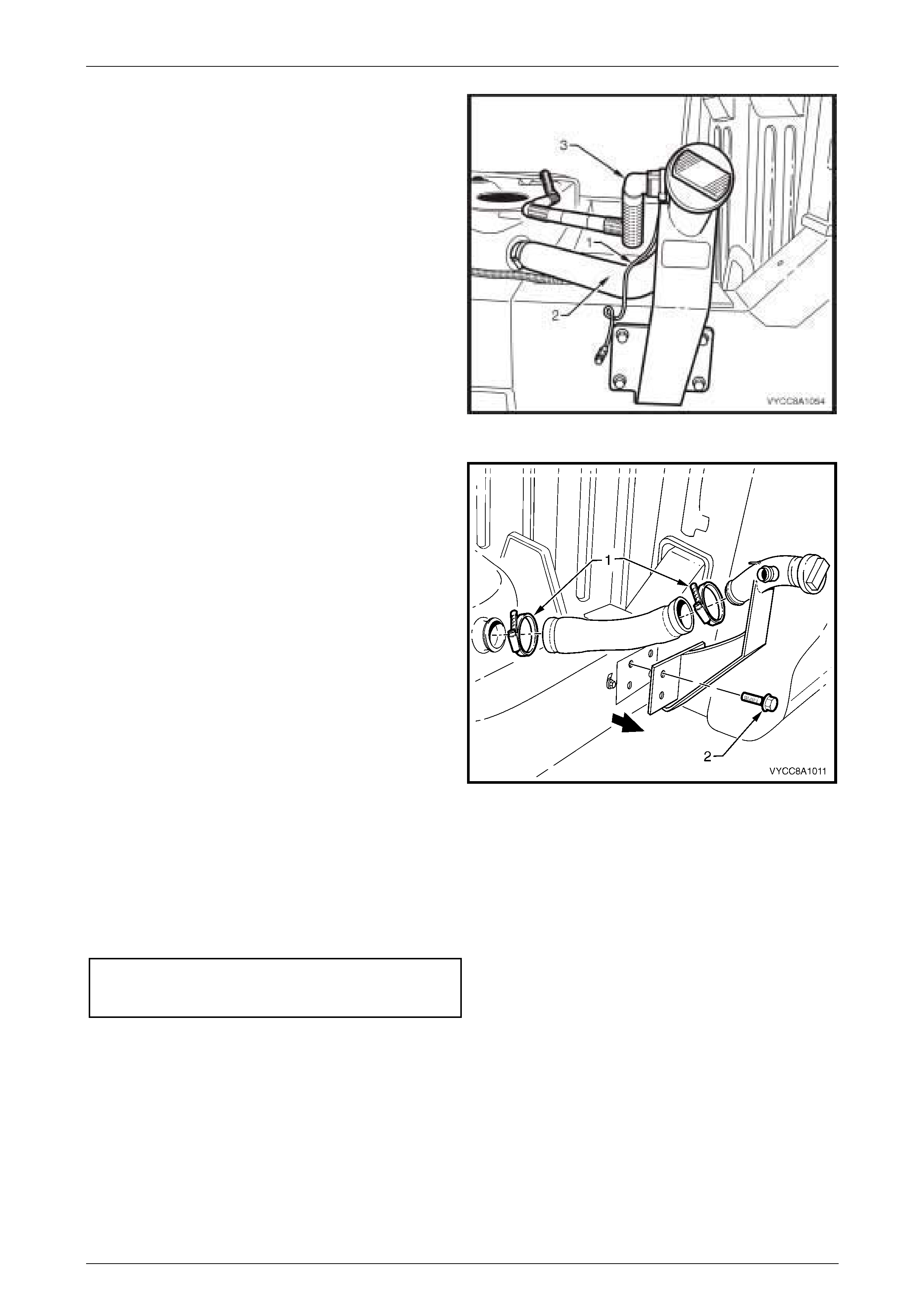
3 Remove the earthing wire (1) from the spade
connector on the fuel filler neck.
4 Remove the earthing wire from the spade connector
screw mounting on the chassis member.
5 Place the earthing wire in a safe location away from
the immediate worksite.
6 Loosen the screw clamp holding the flexible fuel inlet
pipe (2) onto the fuel filler neck.
7 Use compressed air to ensure that all dirt and foreign
materials are removed from the inlet breather pipe (3)
and fuel filler neck.
8 Remove the quick-connect fitting holding the inlet
breather pipe onto the fuel filler neck.
9 Cover the flexible fuel inlet pipe and inlet breather
pipe with a suitable material to prevent foreign objects
from entering.
Figure 8A1 – 17
10 Remove both screw clamps (1) holding the flexible
fuel inlet pipe onto the fuel filler neck.
11 Remove the four screws (2) holding the support
bracket backing plate onto the chassis.
12 Cover the flexible fuel filler neck with a suitable
material to prevent foreign objects from entering.
Figure 8A1 – 18
Reinstall
The installation procedure is the reverse of the removal procedure, noting the following:
1 Ensure all parts are dust-free and clean before reinstalling.
2 Tighten the screws that secure the support bracket backing plate on the chassis to the correct torque specification.
Support bracket backing
plate attaching screws
torque specification................................20.0 – 25.0 Nm
Fuel Tank Page 8A1–20
Page 8A1–20
2.4 Modular Fuel Pump and Sender
Assembly — V6
Remove
A depressurised fuel system contains fuel in
the fuel filter and fuel lines that can be spilled
during service operations.
Fuel vapour remains in the fuel tank even
when completely empty. Seal all openings in
the fuel tank using suitable material or a
plastic plug. Ensure no naked flames or other
ignition sources are nearby. Ensure all
mobile phones (and transmission devices
that may cause any metal objects to become
unintentional receiving antennas) are
switched off.
Wear safety glasses when using compressed
air. Do not blow compressed air directly onto
any body part.
1 Remove the tray, refer to Section 1B1, Tray.
2 Use compressed air to ensure that all dirt and foreign materials are removed from all fuel connections before the
parts are disconnected.
Before proceeding, clean all traces of dirt and
other foreign material from the top of the fuel
tank, near the modular fuel pump and sender
assembly.
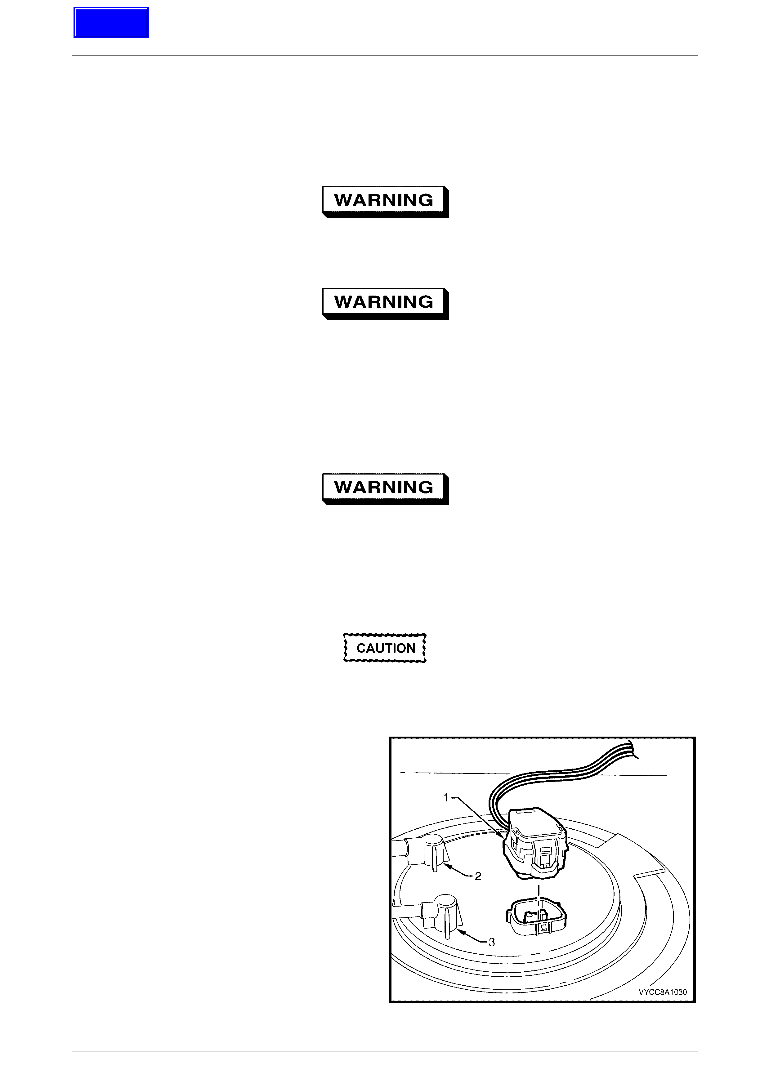
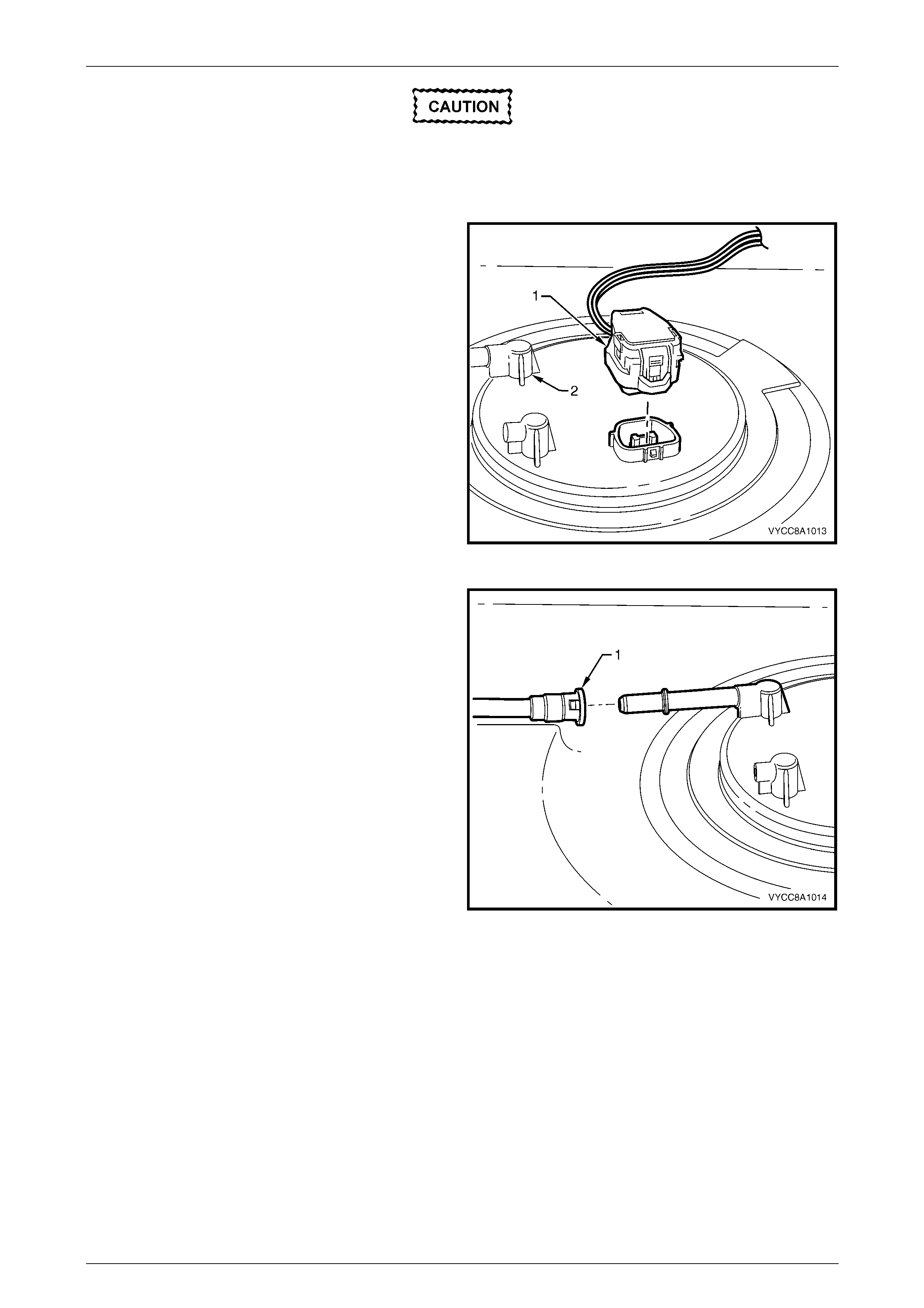
3 Disconnect the modular fuel pump and sender
assembly harness connector (1).
4 Tag the fuel feed line connecting the fuel feed port (2)
on top of the modular fuel pump and sender
assembly.
5 Tag the fuel return line connecting the fuel return
port (3) on top of the modular fuel pump and sender
assembly.
Figure 8A1 – 19
Techline
Fuel Tank Page 8A1–21
Page 8A1–21
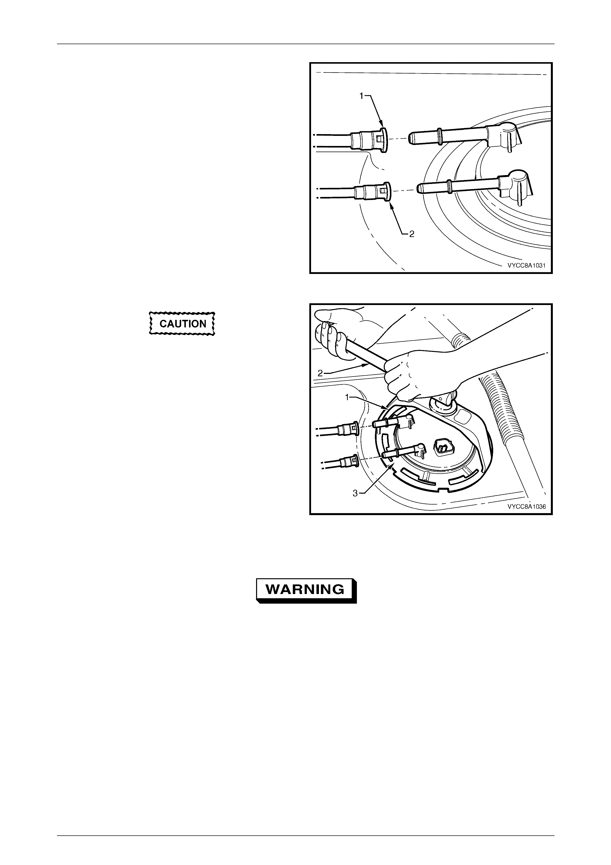
6 Disengage the fuel feed line quick-connect fitting (1)
using special tool AU533 (3/8-inch).
7 Disengage the fuel return line quick-connect fitting (2)
using special tool AU533 (5/16-inch).
NOTE
For information on quick-connect fittings for cab
chassis vehicles, refer to MY 2003 VY and V2
Series Service Information, Section 8A1 Fuel
Tank, 2.10 Quick-connect Fittings.
Figure 8A1 – 20
Ensure special tool J45722 is seated firmly
and positively in the modular fuel pump and
sender assembly cover retainer lock ring
while removing the modular fuel pump and
sender assembly.
8 Using special tool J45722 (1) and a half-inch breaker
bar (2), remove the modular fuel pump and sender
assembly cover retainer lock ring (3) by turning in an
anti-clockwise direction.
9 Remove the modular fuel pump and sender assembly
cover retainer lock ring.
NOTE
The modular fuel pump and sender assembly
cover springs up when the retainer is removed.
Figure 8A1 – 21
The reservoir will be full of fuel. When the
modular fuel pump and sender assembly is
removed from the fuel tank, pour any
remaining fuel in the reservoir into a suitable
container. Do not drain or store fuel into an
open container, due to the possibility of fire
or explosion.
10 Carefully lift the modular fuel pump and sender assembly from the fuel tank, taking care not to:
• damage the fuel level sender float and arm, and
• spill any fuel remaining in the reservoir.
Fuel Tank Page 8A1–22
Page 8A1–22
NOTE
The fuel sender float arm is not serviced
separately. If damaged, it is replaced as part of
the fuel level sender assembly.
Fuel vapour remains in the tank even when
completely empty. Seal all the openings in
the fuel tank using suitable material or a
suitable plastic plug.
11 Place a suitable material over the opening in the fuel tank to prevent any foreign matter from entering the fuel
system.
12 Remove and discard the sealing O-ring and spacer.
Test
Fuel Level Sender
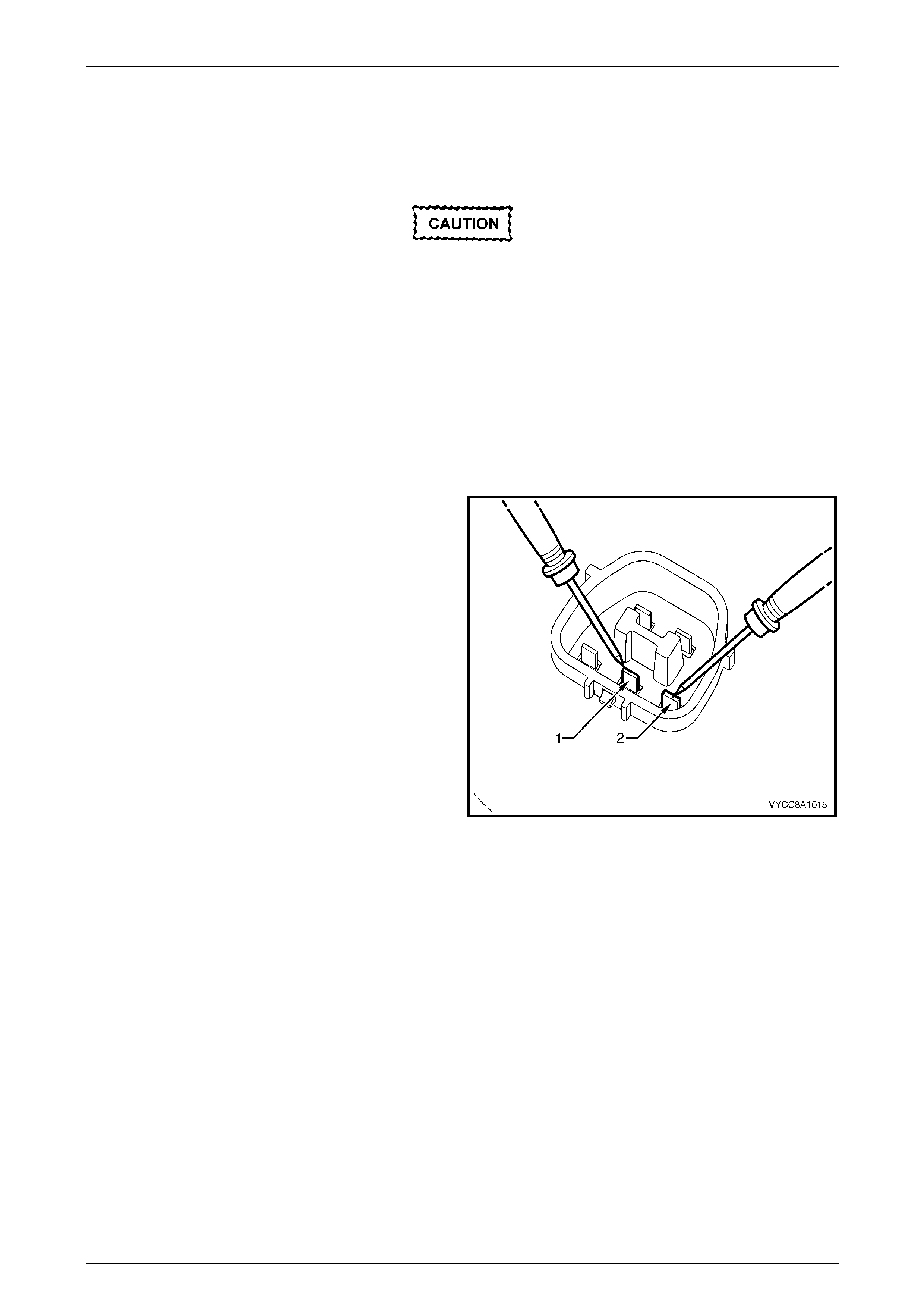
1 Measure the resistance across the positive (1) and
negative (2) fuel level sender terminals of the fuel
pump motor connector. Take the following
measurements:
a With the fuel level sender assembly in the empty
position, the resistance should be 40 ohms
(+/–2.5 ohms).
b With the fuel level sender assembly rotated to
the full position, the resistance should be
248.5 ohms (+/–3.3 ohms).
2 If the resistance at either of these positions is not
within tolerance, replace the fuel level sender
assembly, refer to 2.7 Fuel Level Sender Assembly.
Figure 8A1 – 22
Fuel Tank Page 8A1–23
Page 8A1–23
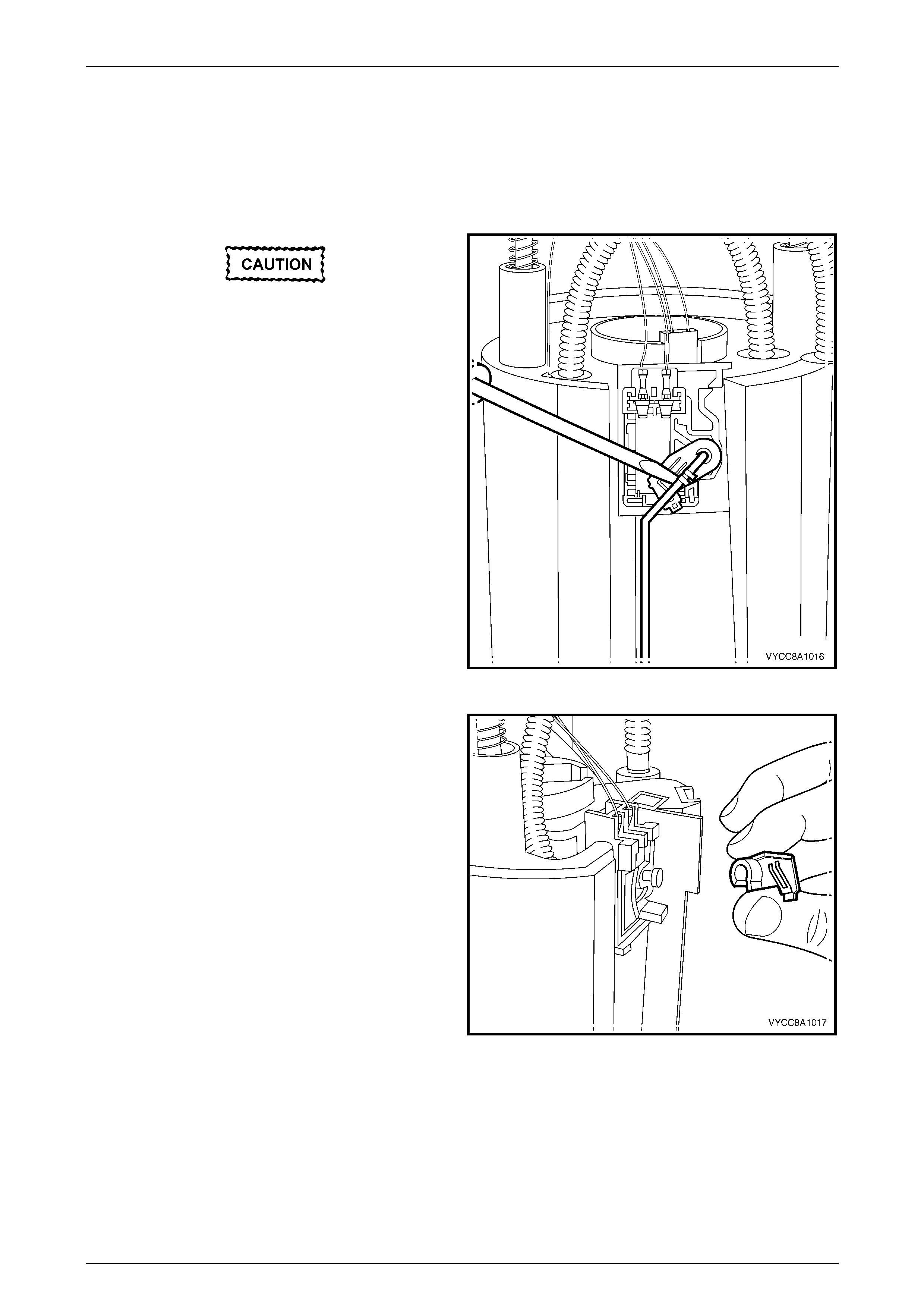
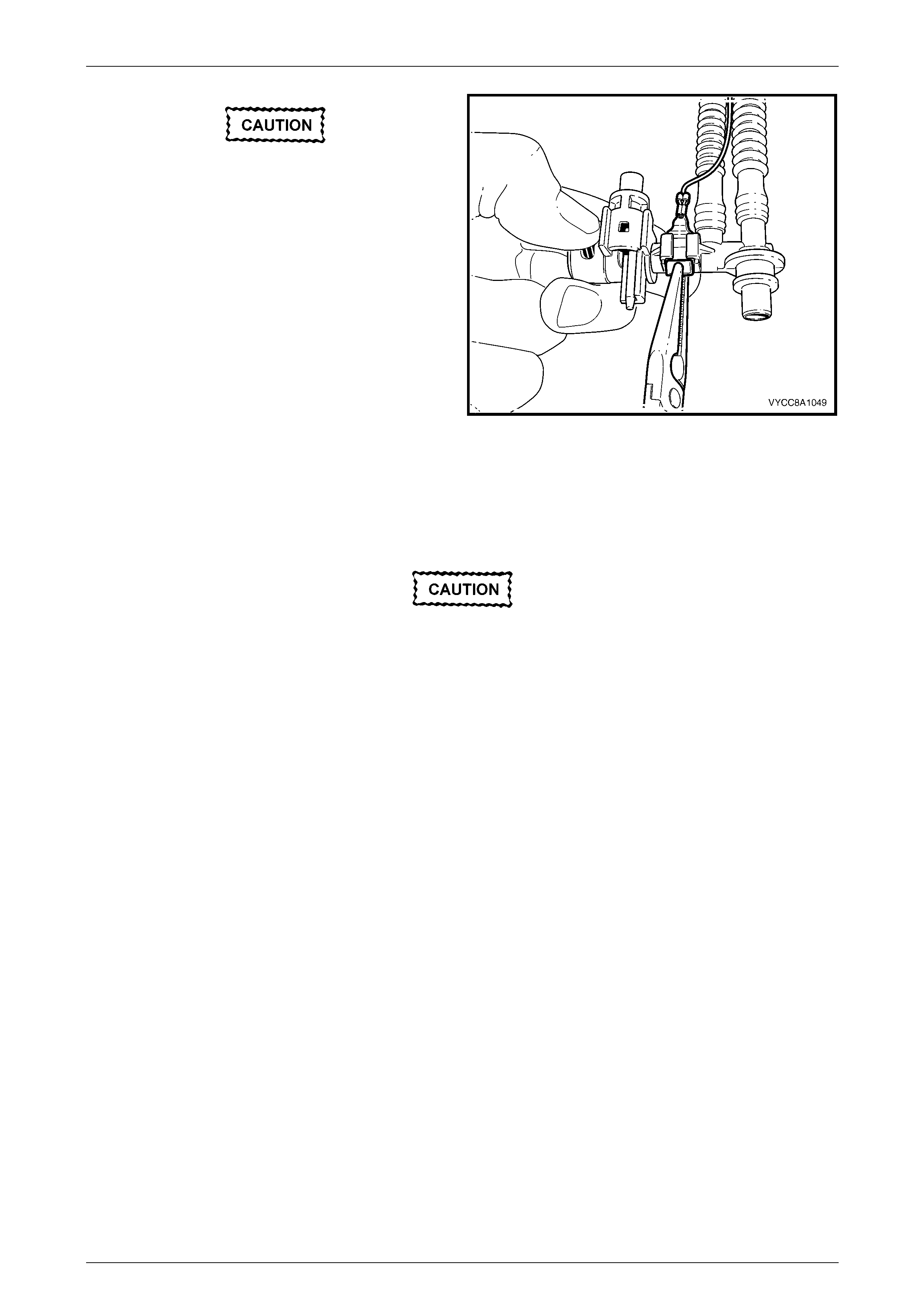
Disassemble
Do not touch the variable resistor card; if it is
touched inadvertently, clean it immediately
with isopropyl alcohol.
1 Prise the tang open that holds the fuel level sender
float and arm onto the nylon wiper piece.
2 Lift the fuel level sender float and arm away from the
nylon wiper piece and place in a safe location away
from the immediate worksite.
Figure 8A1 – 23
3 Lift the nylon wiper piece off the variable resistor card
holder, then place in a safe location away from the
immediate worksite.
Figure 8A1 – 24

Fuel Tank Page 8A1–24
Page 8A1–24
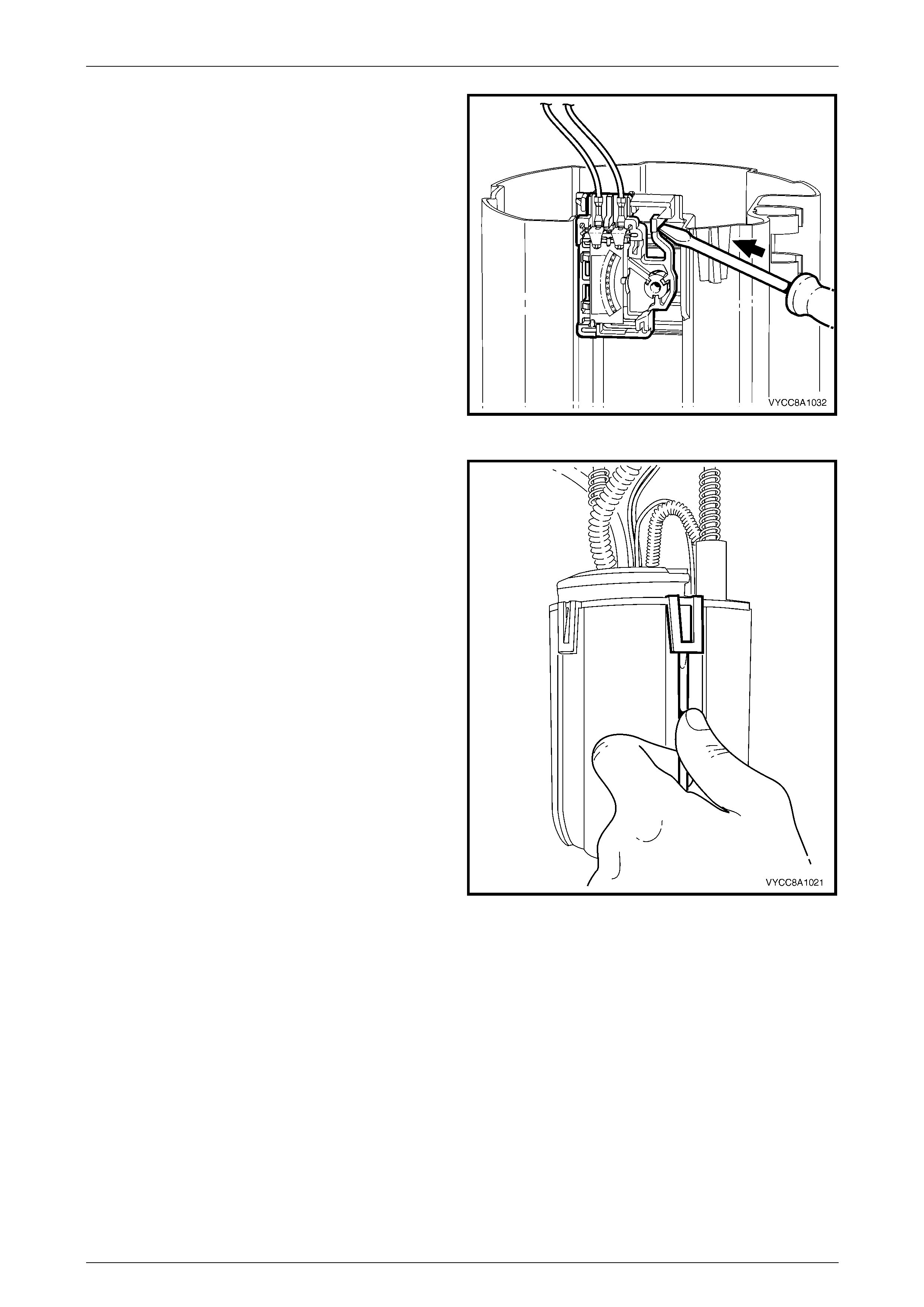
4 Remove the 3-pin connector (the fuel level sender
assembly wires) from underneath the modular fuel
pump and sender assembly cover.
Figure 8A1 – 25
5 Remove the 2-pin connector (the fuel pump motor
wires) from underneath the modular fuel pump and
sender assembly cover.
Figure 8A1 – 26

Fuel Tank Page 8A1–25
Page 8A1–25
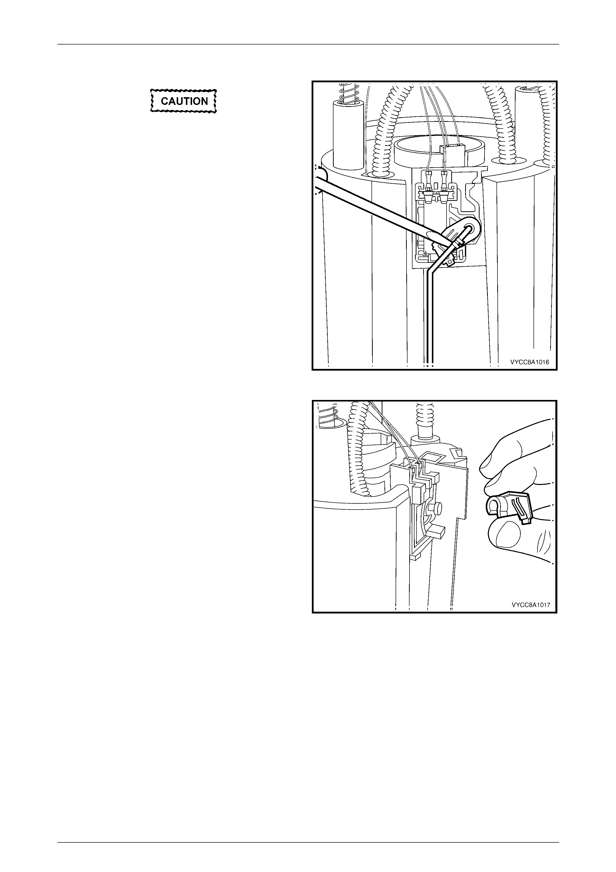
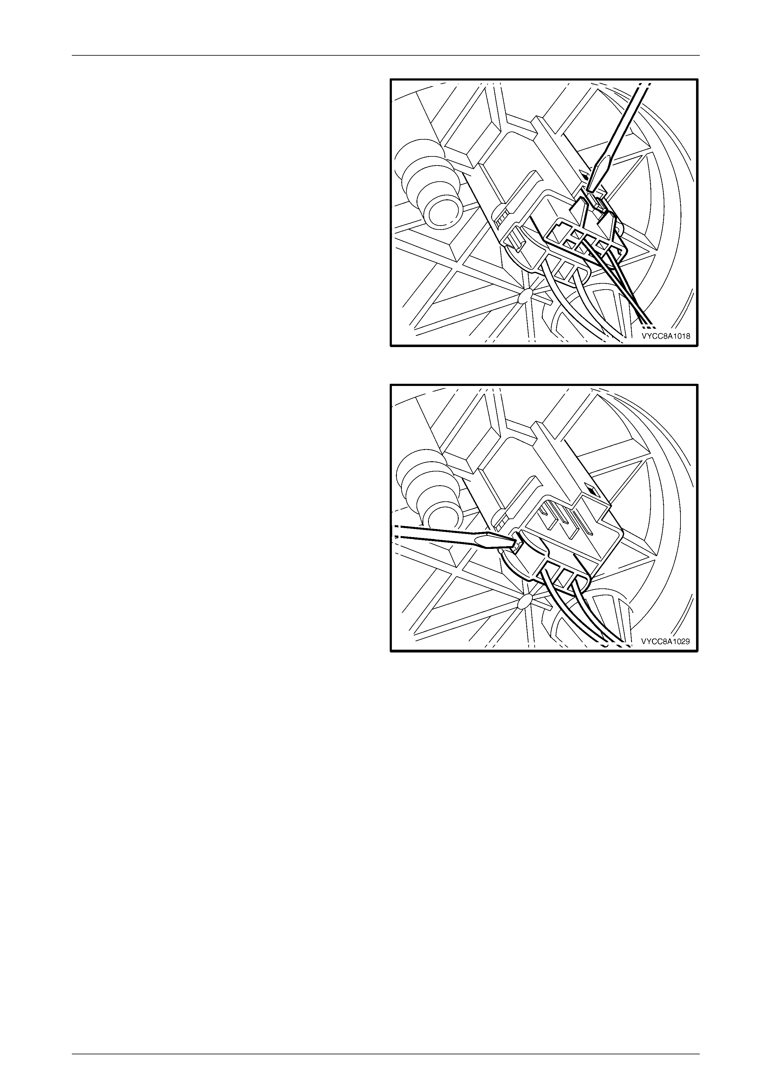
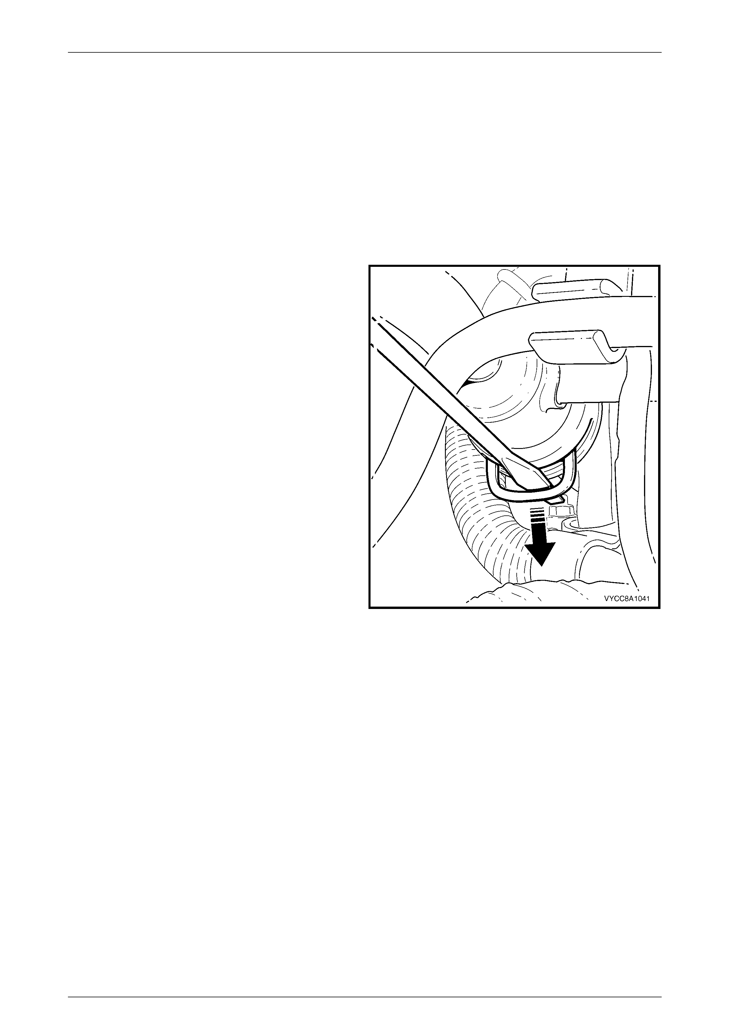
6 Prise the transfer jet pump from the clips, then remove
from the reservoir.
Figure 8A1 – 27
7 Press in the tang retaining the 2-pin connector on the
fuel pump and suction filter assembly, then remove
the connector.
Figure 8A1 – 28

Fuel Tank Page 8A1–26
Page 8A1–26
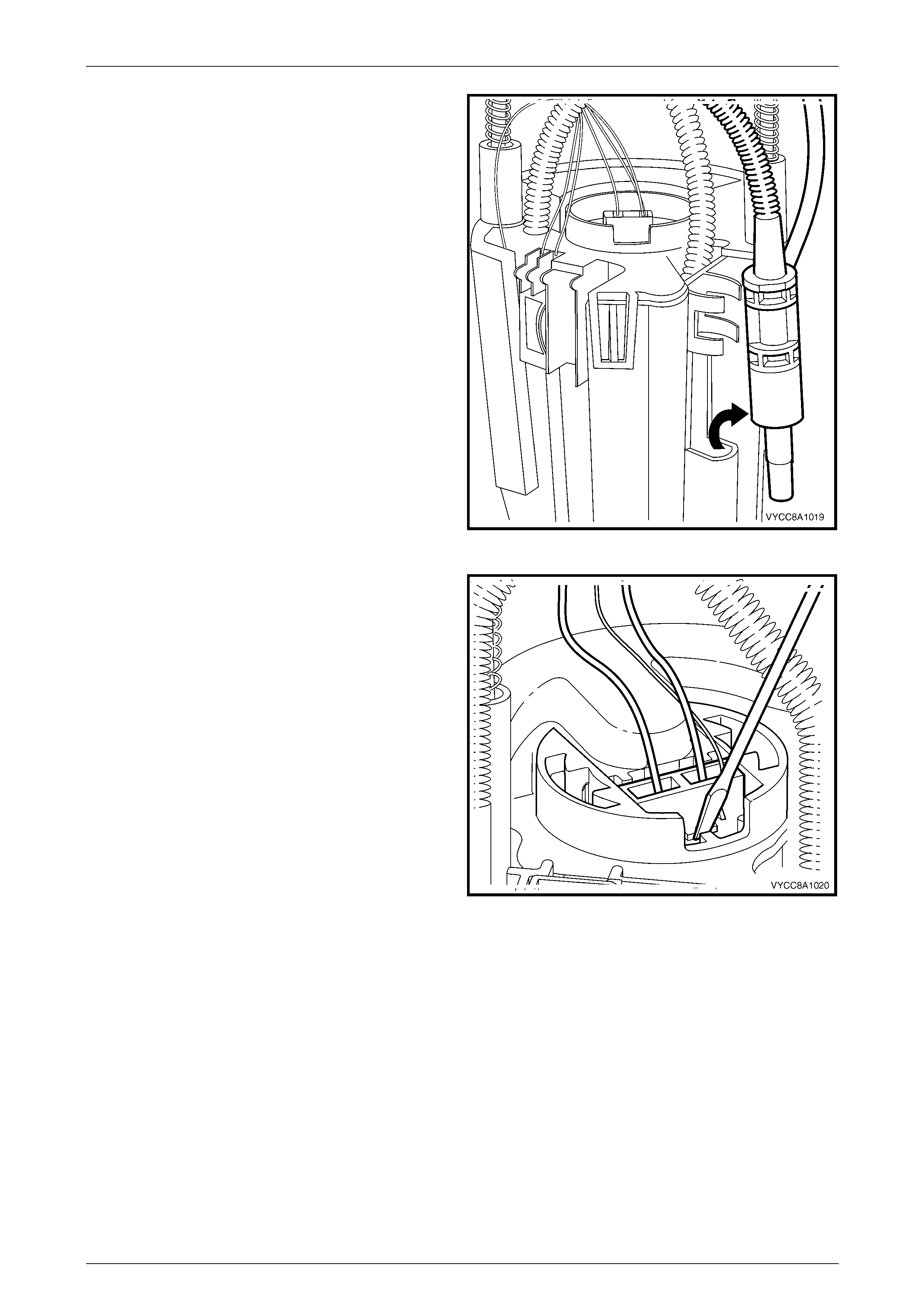
8 Prise the tang open that holds the variable resistor
card holder to the side of the reservoir, then lift it off
the reservoir.
Figure 8A1 – 29
9 Prise the four tangs with a flat-bladed screwdriver,
then remove the fuel pump and suction filter
assembly, and modular fuel pump and sender
assembly cover from the reservoir.
NOTE
Another person may have to assist in removing
the fuel pump and suction filter assembly from
the reservoir.
Figure 8A1 – 30
Fuel Tank Page 8A1–27
Page 8A1–27
Do not bend the spade connector on the
pressure regulator holder; this can be easily
damaged or broken.
10 Pull the modular fuel pump and sender assembly
cover, fuel pump and suction filter assembly, pressure
regulator holder, and fuel feed pipe and fuel return
pipe from the reservoir body.
NOTE
Some difficulty may be experienced when lifting
these items from the reservoir body due to the
limited space available.
Figure 8A1 – 31
11 Remove and discard the O-ring (1) from the bottom of
the pressure regulator holder.
NOTE
The O-ring may be lodged in the reservoir body.
12 Remove and discard the O-ring (2) from the top of the
pressure regulator holder.
NOTE
The O-ring may be lodged either in the base of
the fuel pump and suction filter assembly.
Figure 8A1 – 32

Fuel Tank Page 8A1–28
Page 8A1–28
13 Prise open both tangs on the fuel outlet connector on
the bottom of the fuel pump and suction filter
assembly, then remove the fuel outlet pipe from the
fuel pump and suction filter assembly.
14 Remove and discard the O-ring from the fuel feed line
outlet underneath the fuel pump and suction filter
assembly.
NOTE
The O-ring may remain in the base of the fuel
pump and suction filter assembly.
Figure 8A1 – 33
15 Push the fuel pump and suction filter assembly down
the sprung shafts and remove the circlip (only one
shaft is fitted with a circlip) from the end of the shaft.
Place the circlip in a safe location away from the
immediate worksite.
Figure 8A1 – 34
Fuel Tank Page 8A1–29
Page 8A1–29
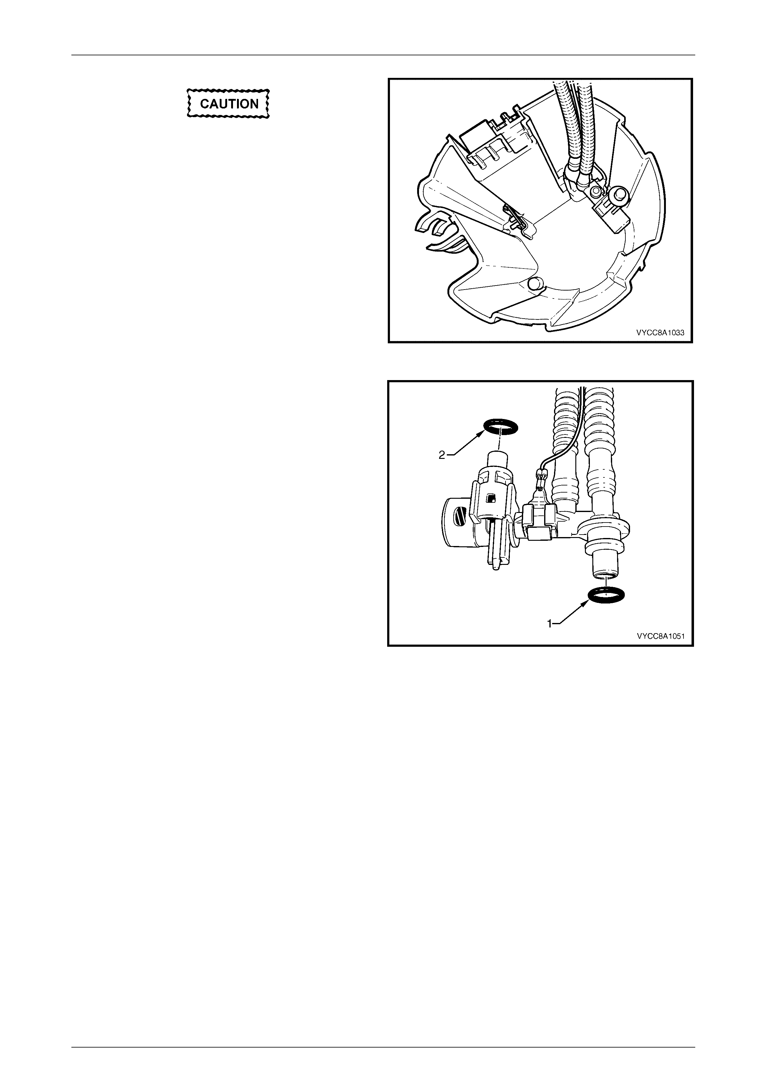
Reassemble
The procedure for reassembling the modular fuel pump and sender assembly is the reverse of the disassembly
procedure, noting the following:
1 Locate and press the fuel outlet connector to its
position on the bottom of the fuel pump and suction
filter assembly (looping the fuel outlet pipe through the
recess near the right-side top when the fuel filter
assembly is on the side facing away from you).
Figure 8A1 – 35
2 Ensure the wires to both electrical connectors and the variable resistor card are inboard of the fuel feeder pipe.
3 Ensure the wires to the variable resistor card and both connectors do not interfere when reassembling the fuel
pump and suction filter assembly into the reservoir.
Reinstall
The procedure for reinstalling the modular fuel pump and sender assembly is the reverse of the removal procedure,
noting the following:
1 Position a new O-ring seal in the fuel tank recess.
2 Rest the modular fuel pump and sender assembly on a flat surface.
3 Measure the distance between the centre of the fuel sender float and the flat surface.
4 Ensure the centre of the fuel level sender float is a nominal 18.5 mm above the surface. If not, carefully bend the
fuel level sender float arm to achieve the required distance.

Fuel Tank Page 8A1–30
Page 8A1–30
NOTE
Do not damage the fuel level sender float and
arm when placing the modular fuel pump and
sender assembly into the fuel tank.
5 Ensure the low fuel level feed pipe is located in the
fuel tank correctly (that is, on the side of the baffle
furthest away from the modular fuel pump and sender
assembly).
6 Ensure the locator in the modular fuel pump and
sender assembly cover engages in the slot in the tank
opening.
Figure 8A1 – 36
Fuel Tank Page 8A1–31
Page 8A1–31
2.5 Modular Fuel Pump and Sender
Assembly — GEN III V8
Remove
A depressurised fuel system contains fuel in
the fuel filter and fuel lines that can be spilled
during service operations.
Fuel vapour remains in the fuel tank even
when completely empty. Seal all openings in
the fuel tank using suitable material or a
plastic plug. Ensure no naked flames or other
ignition sources are nearby. Ensure all
mobile phones (and transmission devices
that may cause any metal objects to become
unintentional receiving antennas) are
switched off.
Wear safety glasses when using compressed
air. Do not blow compressed air directly onto
any body part.
1 Remove the tray, refer to Section 1B1, Tray.
2 Use compressed air to ensure that all dirt and foreign materials are removed from all fuel connections before the
parts are disconnected.
Techline
Fuel Tank Page 8A1–32
Page 8A1–32
Before proceeding, clean all traces of dirt and
other foreign material from the top of the fuel
tank, near the modular fuel pump and sender
assembly.
3 Disconnect the modular fuel pump and sender
assembly harness connector (1).
4 Tag the fuel feed line connecting the fuel feed port (2)
on top of the modular fuel pump and sender
assembly.
Figure 8A1 – 37
5 Disengage the fuel feed line quick-connect fitting (1)
using special tool AU533 (3/8-inch).
NOTE
For information on quick-connect fittings for cab
chassis vehicles, refer to MY 2003 VY and V2
Series Service Information, Section 8A1 Fuel
Tank, 2.10 Quick-connect Fittings.
Figure 8A1 – 38
Fuel Tank Page 8A1–33
Page 8A1–33
Ensure special tool J45722 is seated firmly
and positively in the modular fuel pump and
sender assembly cover retainer lock ring
while removing the modular fuel pump and
sender assembly.
6 Using special tool J45722 (1) and a half-inch breaker
bar (2), remove the modular fuel pump and sender
assembly cover retainer lock ring (3) by turning in an
anti-clockwise direction.
7 Remove the modular fuel pump and sender assembly
cover retainer lock ring.
NOTE
The modular fuel pump and sender assembly
cover springs up when the retainer is removed.
Figure 8A1 – 39
The reservoir will be full of fuel. When the
modular fuel pump and sender assembly is
removed from the fuel tank, pour any
remaining fuel in the reservoir into a suitable
container. Do not drain or store fuel into an
open container, due to the possibility of fire
or explosion.
8 Carefully lift the modular fuel pump and sender assembly from the fuel tank, taking care not to:
• damage the fuel level sender float and arm, and
• spill any fuel remaining in the reservoir.
NOTE
The fuel sender float arm is not serviced
separately. If damaged, it is replaced as part of
the fuel level sender assembly.
Fuel vapour remains in the tank even when
completely empty. Seal all the openings in
the fuel tank using suitable material or a
suitable plastic plug.
9 Place a suitable material over the plugged opening in the fuel tank to prevent any foreign matter from entering the
fuel system.
10 Remove and discard the sealing O-ring and spacer.
Fuel Tank Page 8A1–34
Page 8A1–34
Test
Fuel Level Sender
1 Measure the resistance across the positive (1) and
negative (2) fuel level sender terminals of the fuel
pump motor connector. Take the following
measurements:
a With the fuel level sender assembly in the empty
position, the resistance should be 40 ohms
(+/–2.5 ohms).
b With the fuel level sender assembly rotated to
the full position, the resistance should be
248.5 ohms (+/–3.3 ohms).
2 If the resistance at either of these positions is not
within tolerance, replace the fuel level sender
assembly, refer to 2.7 Fuel Level Sender Assembly.
Figure 8A1 – 40
Disassemble
Do not touch the variable resistor card; if it is
touched inadvertently, clean it immediately
with isopropyl alcohol.
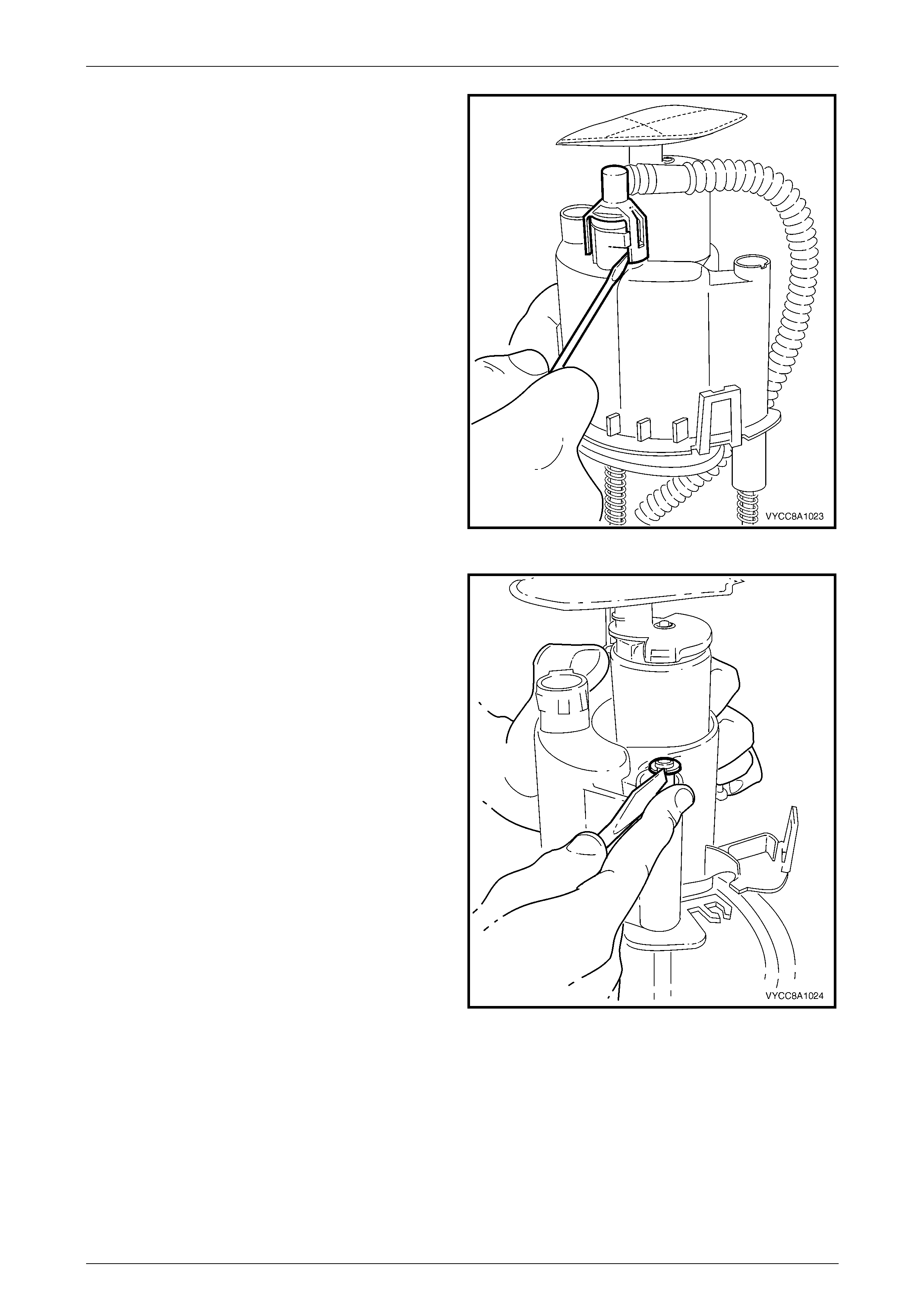
1 Prise the tang open that holds the fuel level sender
float and arm onto the nylon wiper piece.
2 Lift the fuel level sender float and arm away from the
nylon wiper piece and place in a safe location away
from the immediate worksite.
Figure 8A1 – 41
Fuel Tank Page 8A1–35
Page 8A1–35
3 Lift the nylon wiper piece off the variable resistor card
holder, then place in a safe location away from the
immediate worksite.
Figure 8A1 – 42
4 Remove the 3-pin connector (the fuel level sender
assembly wires) from underneath the modular fuel
pump and sender assembly cover.
Figure 8A1 – 43
5 Remove the 2-pin connector (the fuel pump motor
wires) from underneath the modular fuel pump and
sender assembly cover.
Figure 8A1 – 44

Fuel Tank Page 8A1–36
Page 8A1–36
6 Prise the transfer jet pump from the clips, then remove
from the reservoir.
Figure 8A1 – 45
7 Press in the tang retaining the 2-pin connector on the
fuel pump and suction filter assembly, then remove
the connector.
Figure 8A1 – 46
Fuel Tank Page 8A1–37
Page 8A1–37
8 Prise the tang open that holds the variable resistor
card holder to the side of the reservoir, then lift it off
the reservoir.
Figure 8A1 – 47
9 Prise the four tangs with a flat-bladed screwdriver,
then remove the fuel pump and suction filter
assembly, and modular fuel pump and sender
assembly cover from the reservoir.
NOTE
Another person may have to assist in removing
the fuel pump and suction filter assembly from
the reservoir.
Figure 8A1 – 48
Fuel Tank Page 8A1–38
Page 8A1–38
Do not bend the spade connector on the
pressure regulator holder; this can be easily
damaged or broken.
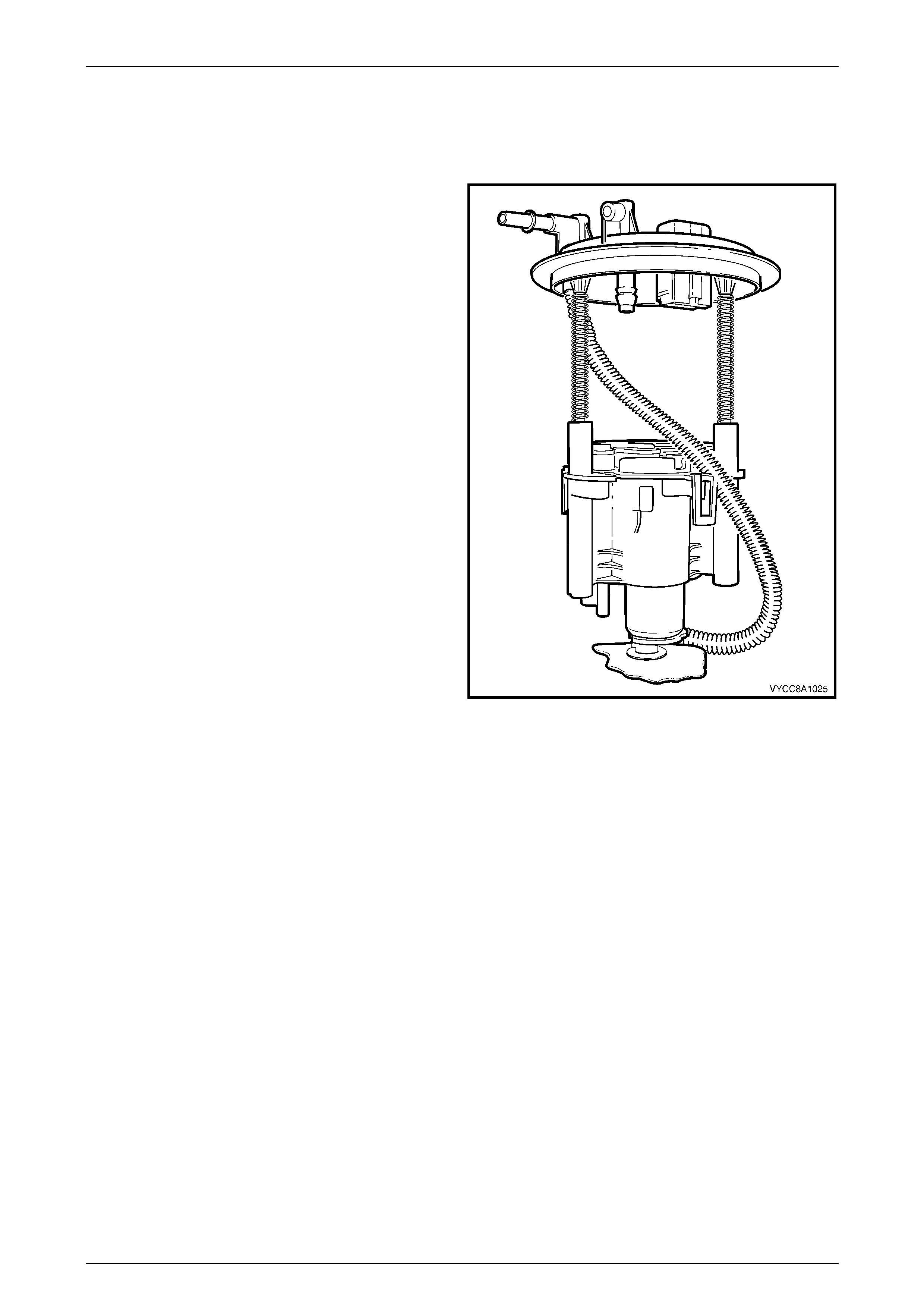
10 Pull the modular fuel pump and sender assembly
cover, fuel pump and suction filter assembly, pressure
regulator holder and fuel feed pipe from the reservoir
body.
NOTE
Some difficulty may be experienced when lifting
these items from the reservoir body due to the
limited space available.
Figure 8A1 – 49
11 Remove and discard the O-ring (1) from the bottom of
the pressure regulator holder.
NOTE
The O-ring may be lodged in the reservoir body.
12 Remove and discard the O-ring (2) from the top of the
pressure regulator holder.
NOTE
The O-ring may be lodged either in the base of
the fuel pump and suction filter assembly.
Figure 8A1 – 50
Fuel Tank Page 8A1–39
Page 8A1–39
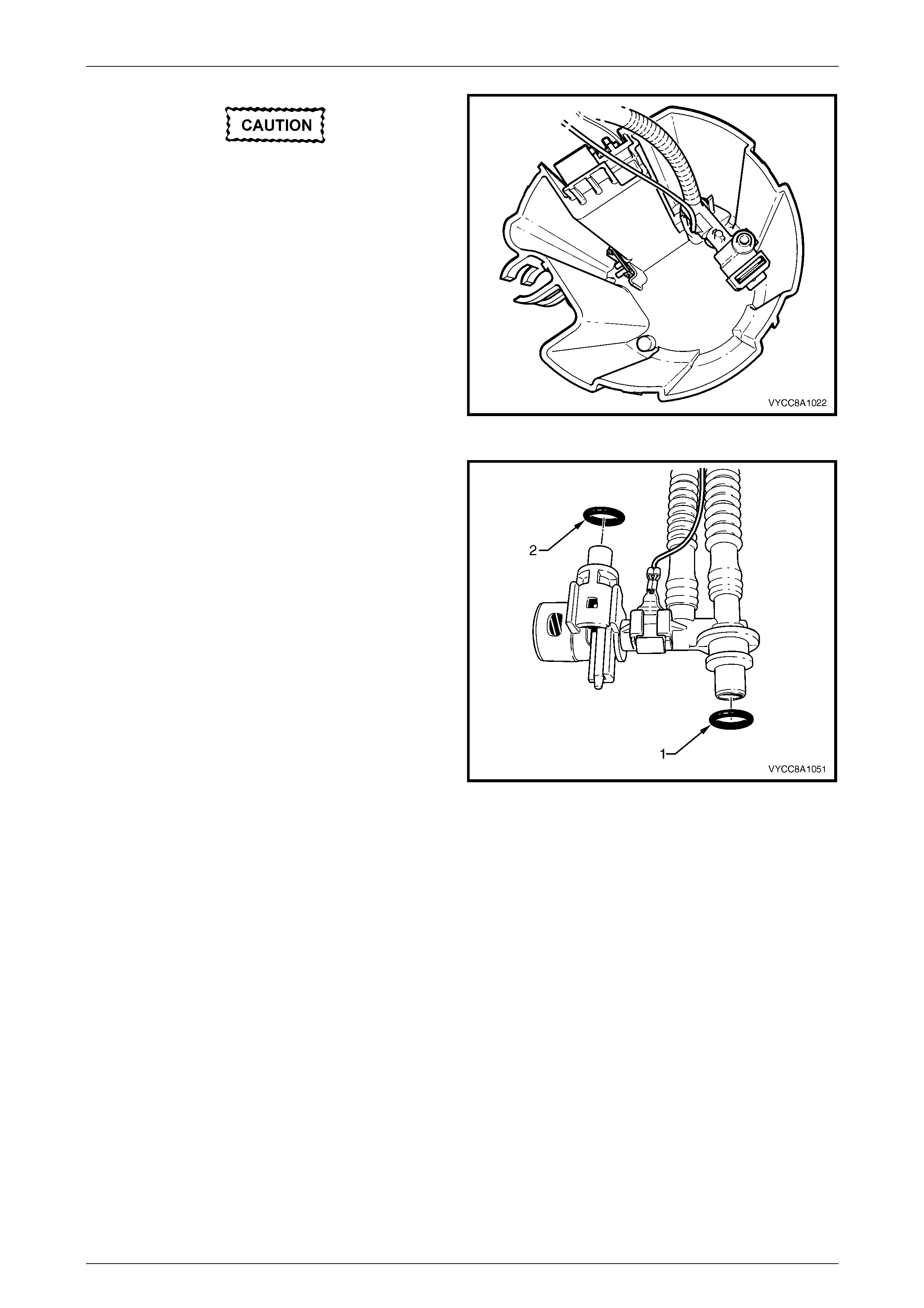
13 Prise open both tangs on the fuel outlet connector on
the bottom of the fuel pump and suction filter
assembly, then remove the fuel outlet pipe from the
fuel pump and suction filter assembly.
14 Remove and discard the O-ring from the fuel feed line
outlet underneath the fuel pump and suction filter
assembly.
NOTE
The O-ring may remain in the base of the fuel
pump and suction filter assembly.
Figure 8A1 – 51
15 Push the fuel pump and suction filter assembly down
the sprung shafts and remove the circlip (only one
shaft is fitted with a circlip) from the end of the shaft.
Place the circlip in a safe location away from the
immediate worksite.
Figure 8A1 – 52
Fuel Tank Page 8A1–40
Page 8A1–40
Reassemble
The procedure for reassembling the modular fuel pump and sender assembly is the reverse of the disassembly
procedure, noting the following:
1 Locate and press the fuel outlet connector to its
position on the bottom of the fuel pump and suction
filter assembly (looping the fuel outlet pipe through the
recess near the right-side top when the fuel filter
assembly is on the side facing away from you).
Figure 8A1 – 53
2 Ensure the wires to the variable resistor card, pressure regulator and both connectors are inboard of the fuel
feeder pipe.
3 Ensure the wires to the variable resistor card, pressure regulator and both connectors do not interfere when
reassembling the fuel pump and suction filter assembly into the reservoir.
Reinstall
The procedure for reinstalling the modular fuel pump and sender assembly is the reverse of the removal procedure,
noting the following:
1 Position a new O-ring seal in the fuel tank recess.
2 Rest the modular fuel pump and sender assembly on a flat surface.
3 Measure the distance between the centre of the fuel sender float and the flat surface.
4 Ensure the centre of the fuel level sender float is a nominal 18.5 mm above the surface. If not, carefully bend the
fuel level sender float arm to achieve the required distance.
Fuel Tank Page 8A1–41
Page 8A1–41
NOTE
Do not damage the fuel level sender float and
arm when placing the modular fuel pump and
sender assembly into the fuel tank.
5 Ensure the low fuel level feed pipe is located in the
fuel tank correctly (that is, on the side of the baffle
furthest away from the modular fuel pump and sender
assembly).
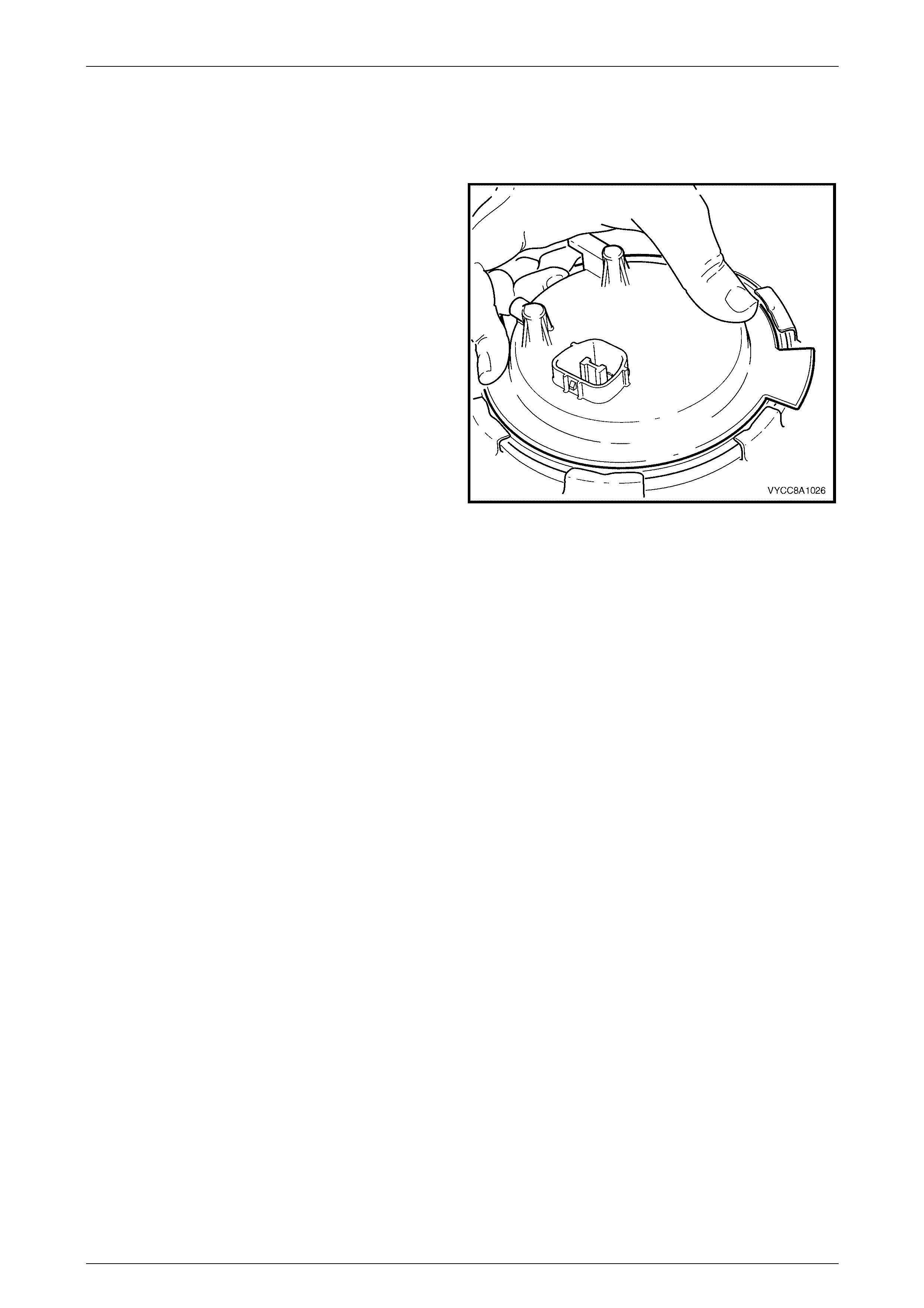
6 Ensure the locator in the modular fuel pump and
sender assembly cover engages in the slot in the tank
opening.
Figure 8A1 – 54

Fuel Tank Page 8A1–42
Page 8A1–42
2.6 Fuel Filter Assembly
Remove
Remove the fuel filter assembly from the modular fuel pump and sender assembly, refer to the removal procedure in
2.9 Suction Filter.
Reinstall
Reinstallation of the fuel filter assembly is the reverse of the removal procedure, refer to 2.9 Suction Filter.
Fuel Tank Page 8A1–43
Page 8A1–43
2.7 Fuel Level Sender Assembly
Disassemble
1 Remove the modular fuel pump and sender assembly from the fuel tank, refer to 2.4 Modular Fuel Pump and
Sender Assembly — V6 or 2.5 Modular Fuel Pump and Sender Assembly — GEN III V8.
Do not touch the variable resistor card; if it is
touched inadvertently, clean it immediately
with isopropyl alcohol.
2 Prise the tang open that holds the fuel level sender
float and arm onto the nylon wiper piece.
3 Lift the fuel level sender float and arm away from the
nylon wiper piece and place in a safe location away
from the immediate worksite.
Figure 8A1 – 55
4 Lift the nylon wiper piece off the variable resistor card
holder, then place in a safe location away from the
immediate worksite.
Figure 8A1 – 56
Fuel Tank Page 8A1–44
Page 8A1–44
5 Remove the 3-pin connector (the fuel level sender
assembly wires) from underneath the modular fuel
pump and sender assembly cover.
Figure 8A1 – 57
6 Remove the 2-pin connector (the fuel pump motor
wires) from underneath the modular fuel pump and
sender assembly cover.
Figure 8A1 – 58
Fuel Tank Page 8A1–45
Page 8A1–45
7 Prise the transfer jet pump from the clips, then remove
from the reservoir.
Figure 8A1 – 59
8 Press in the tang retaining the 2-pin connector on the
fuel pump and suction filter assembly, then remove
the connector.
Figure 8A1 – 60
Fuel Tank Page 8A1–46
Page 8A1–46
9 Prise the tang open that holds the variable resistor
card holder to the side of the reservoir, then lift it off
the reservoir.
Figure 8A1 – 61
10 Prise the four tangs with a flat-bladed screwdriver,
then remove the fuel pump and suction filter
assembly, and modular fuel pump and sender
assembly cover from the reservoir.
NOTE
Another person may have to assist in removing
the fuel pump and suction filter assembly from
the reservoir.
Figure 8A1 – 62
Fuel Tank Page 8A1–47
Page 8A1–47
11 Pull the modular fuel pump and sender assembly
cover, fuel pump and suction filter assembly, pressure
regulator holder and fuel feed pipe (and fuel return
pipe in vehicles with the V6 engine) from the reservoir
body.
NOTE
Some difficulty may be experienced when lifting
these items from the reservoir body due to the
limited space available.
Figure 8A1 – 63
11 Remove and discard the O-ring (1) from the bottom of
the pressure regulator holder.
NOTE
The O-ring may be lodged in the reservoir body.
12 Remove and discard the O-ring (2) from the top of the
pressure regulator holder.
NOTE
The O-ring may be lodged either in the base of
the fuel pump and suction filter assembly.
Figure 8A1 – 64
Fuel Tank Page 8A1–48
Page 8A1–48
Do not bend the spade connector on the
pressure regulator holder; this can be easily
damaged or broken.
14 Remove the spade connector from the pressure
regulator holder.
NOTE
The pressure regulator holder for the V6
modular fuel pump and sender assembly is
shown. The spade connector on the GEN III V8
modular fuel pump and sender assembly is on
the opposite side of the pressure regulator
holder.
Figure 8A1 – 65
Reassemble
The procedure for reassembling the fuel level sender assembly is the reverse of the disassembly procedure, noting the
following:
Do not touch the variable resistor card; if it is
touched inadvertently, clean it immediately
with isopropyl alcohol.
NOTE
Do not separate the fuel level sender float arm
from the nylon wiper piece on the replacement
fuel level sender assembly.
Fuel Tank Page 8A1–49
Page 8A1–49
2.8 Pressure Regulator
V6 Engine
NOTE
The pressure regulator in vehicles with the V6
engine is located in the engine bay at the end of
the fuel rail.
Remove
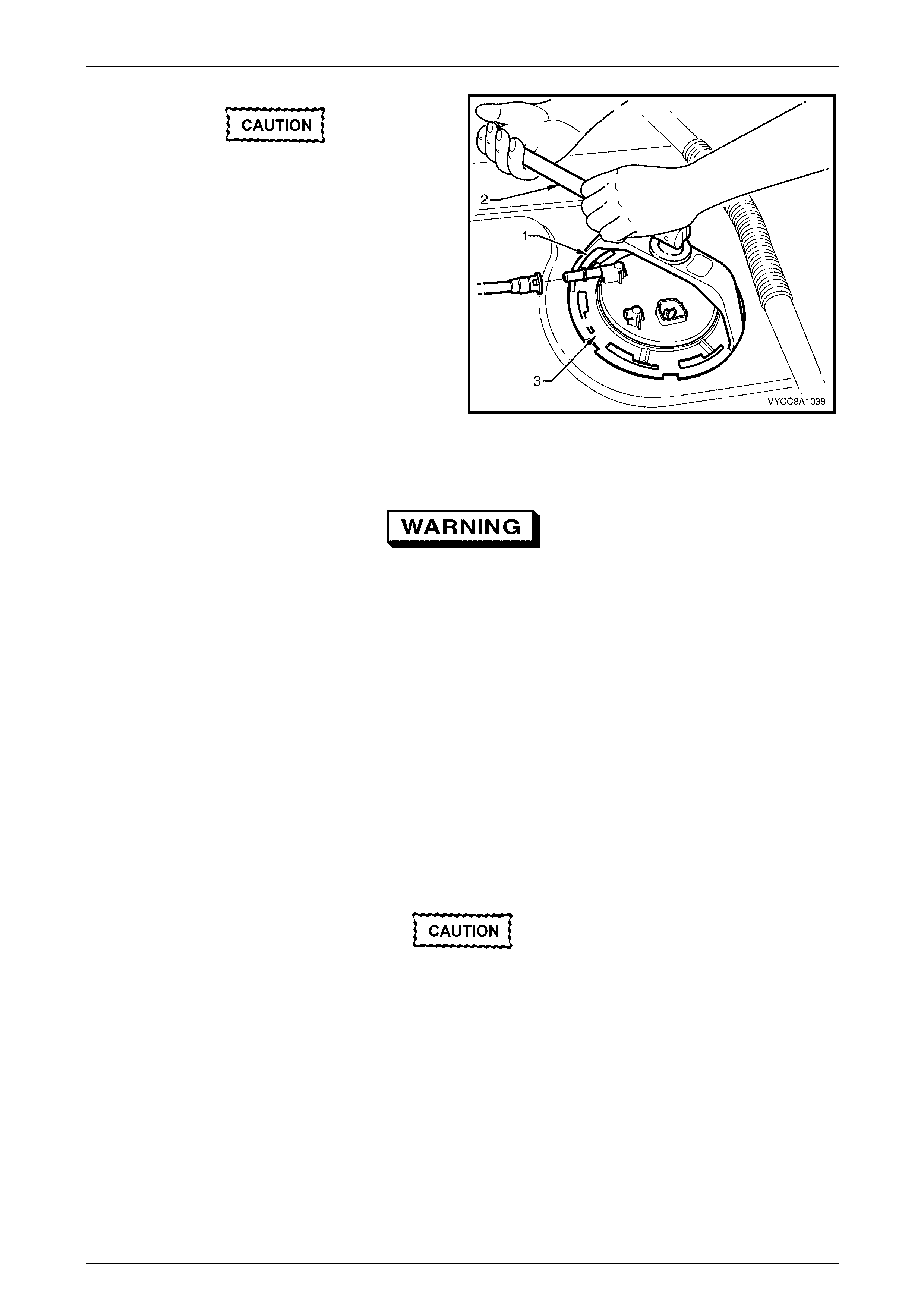
1 Remove the retaining clip from the pressure regulator
holder and place in a safe location away from the
immediate worksite.
2 Prise both halves of the pressure regulator holder
apart and pull the pressure regulator from the
pressure regulator holder.
Figure 8A1 – 66
Reinstall
The procedure for reinstalling the pressure regulator is the reverse of the removal procedure.
Fuel Tank Page 8A1–50
Page 8A1–50
GEN III V8 Engine
Remove
1 Remove the modular fuel pump and sender assembly from the fuel tank, refer to the removal procedure in
2.5 Modular Fuel Pump and Sender Assembly — GEN III V8.
2 Disassemble the modular fuel pump and sender assembly, refer to the disassembly procedure in
2.5 Modular Fuel Pump and Sender Assembly — GEN III V8.
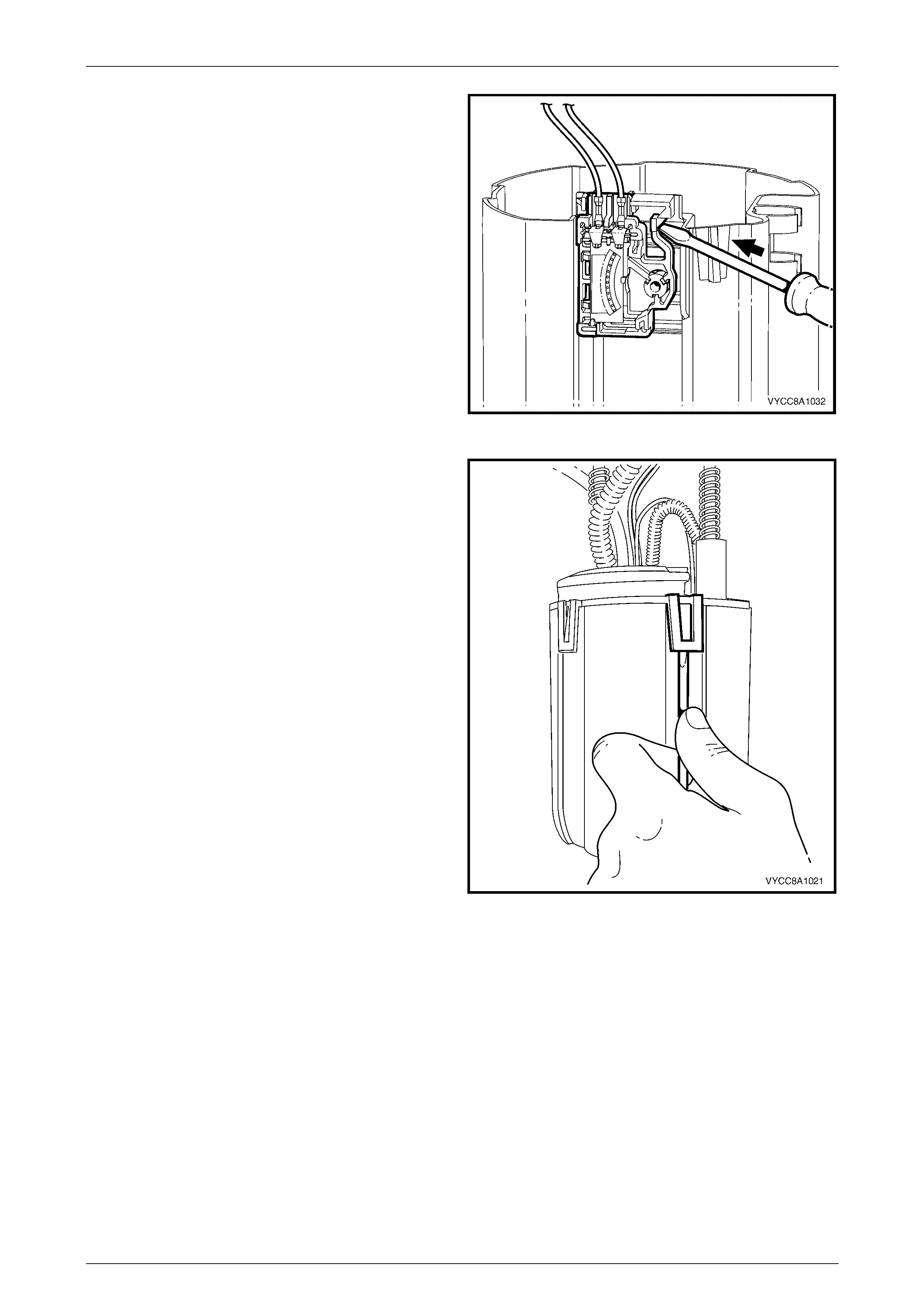
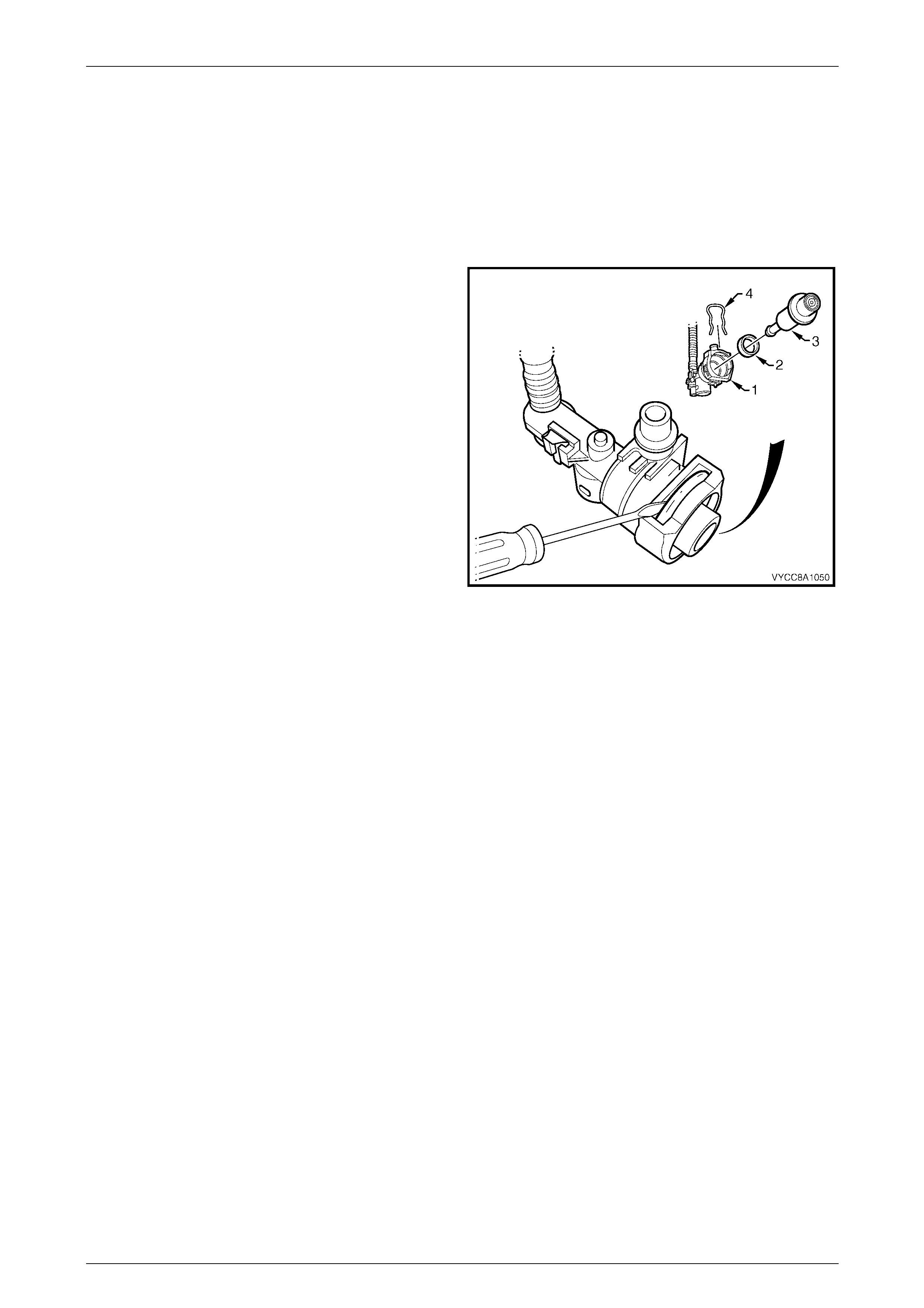
3 Remove the retaining clip (4) from the top of the
pressure regulator holder and place in a safe location
away from the immediate worksite.
4 Using a flat-bladed screwdriver, prise the pressure
regulator (3) from the pressure regulator holder (1).
5 Remove the nylon spacer (2) from the pressure
regulator holder and place in a safe location away
from the immediate worksite.
Figure 8A1 – 67
Reinstall
The procedure for reinstalling the pressure regulator is the reverse of the removal procedure.
Fuel Tank Page 8A1–51
Page 8A1–51
2.9 Suction Filter
The suction filter is attached by an 'easy washer' to the fuel pump end cap. The suction filter is accessible after removal
of the fuel pump and fuel filter from the modular fuel pump and sender assembly reservoir.
Remove
1 Remove the modular fuel pump and sender assembly from the fuel tank, refer to the removal procedure in
2.4 Modular Fuel Pump and Sender Assembly — V6 or 2.5 Modular Fuel Pump and Sender Assembly —
GEN III V8.
2 Disassemble the fuel pump and suction filter assembly, and modular fuel pump and sender assembly cover from
the reservoir, refer to the disassembly procedure in 2.4 Modular Fuel Pump and Sender Assembly — V6 or
2.5 Modular Fuel Pump and Sender Assembly — GEN III V8.
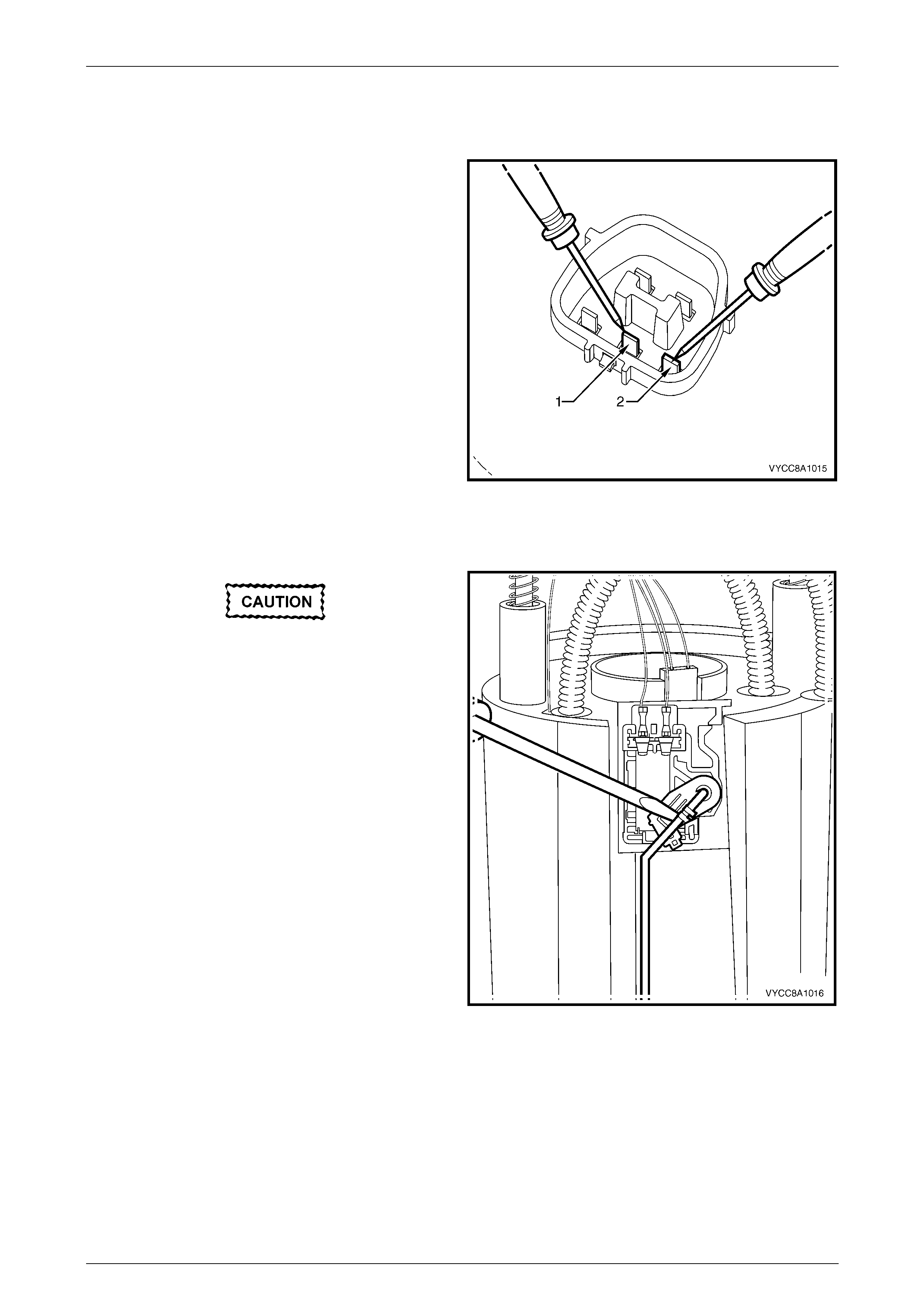
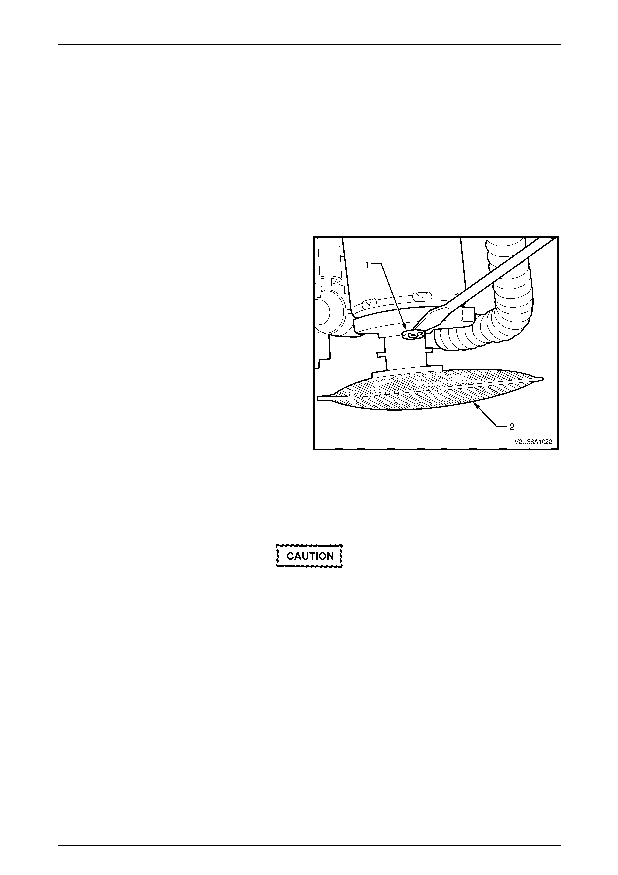
3 Using a suitable blade or a flat-bladed screwdriver,
remove the 'easy washer' (1) from the fuel pump end
cap post.
4 Remove the suction filter (2).
Figure 8A1 – 68
Reinstall
Reinstallation of the suction filter is the reverse of the removal procedure, noting the following:
Check the 'easy washer' for serviceability and
replace if necessary.
Ensure the 'easy washer' is firmly installed along the fuel pump end cap post and firmly pressed up against the suction
filter moulding.
Fuel Tank Page 8A1–52
Page 8A1–52
2.10 Modular Fuel Pump
The modular fuel pump is contained within the fuel filter assembly.
Remove
NOTE
This procedure can not be performed until the
suction filter removal procedure described in 2.9
Suction Filter has been completed.
1 Remove the fuel pump and suction filter assembly from the modular fuel pump and sender assembly, refer to
2.4 Modular Fuel Pump and Sender Assembly — V6 or 2.5 Modular Fuel Pump and Sender Assembly —
GEN III V8.
2 Disassemble the modular fuel pump and sender assembly, refer to 2.4 Modular Fuel Pump and Sender Assembly
— V6 or 2.5 Modular Fuel Pump and Sender Assembly — GEN III V8.
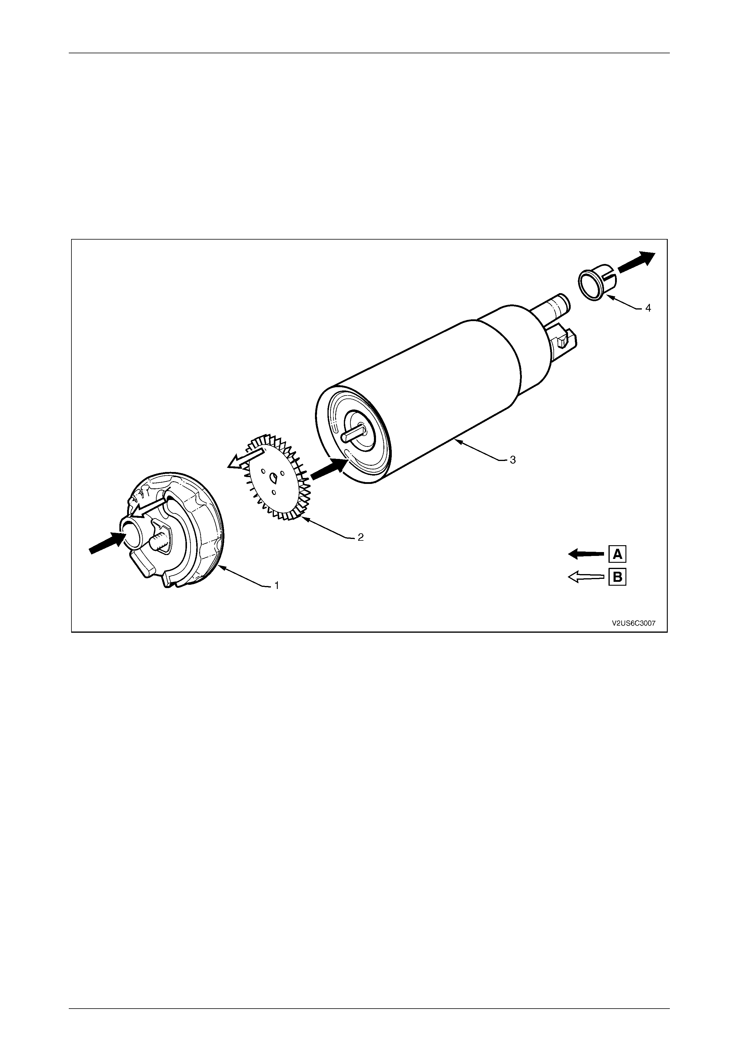
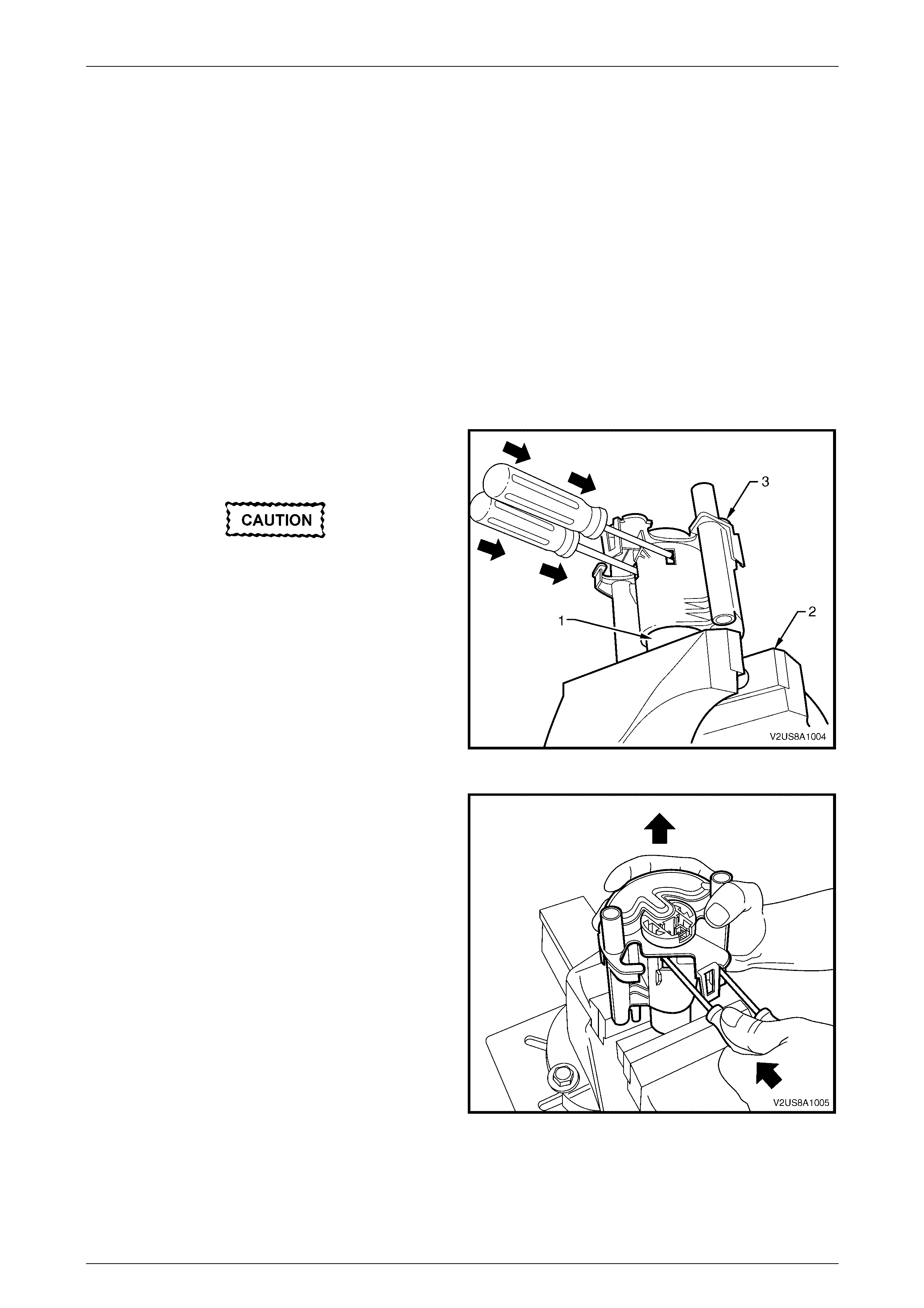
3 Clamp the protruding end of the fuel pump body (1) in
a soft-jawed vice (2) to support the modular fuel pump
and fuel filter assembly (3) in place.
Do not overtighten the vice grips as this may
damage the fuel pump.
4 Insert a medium-sized flat-bladed screwdriver through
each of the service holes in the fuel filter assembly.
5 Slide the screwdriver blade between the fuel pump
end cap and the internal fuel filter clips that hold the
fuel pump body in place.
Figure 8A1 – 69
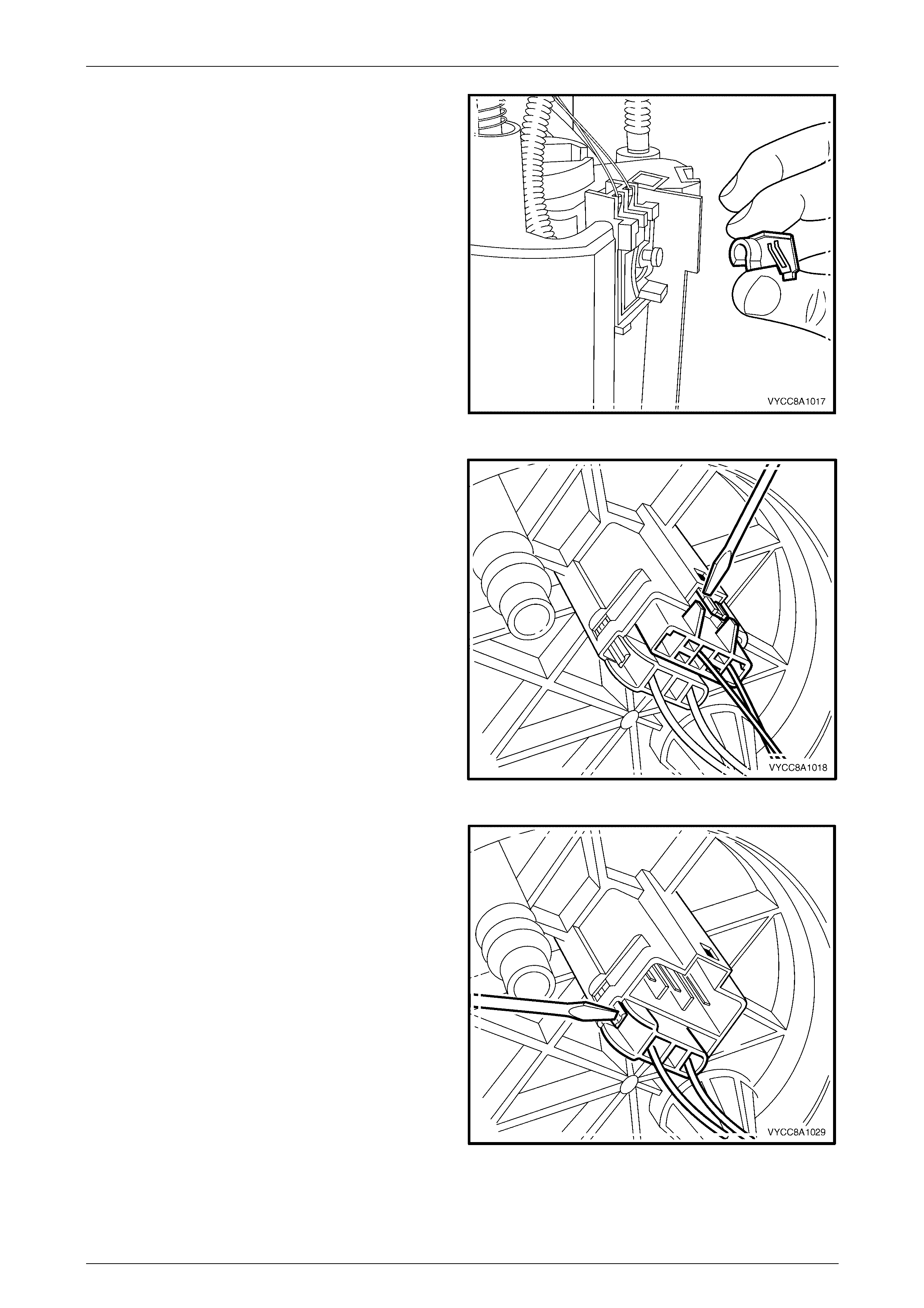
6 Push the screwdrivers in far enough so the internal
fuel filter clips are deflected just free of each of the
fuel pump end cap retainer shoulders.
7 While holding the screwdrivers in place with one
hand, manipulate the fuel filter assembly upwards to
separate it from the fuel pump.
Figure 8A1 – 70
Fuel Tank Page 8A1–53
Page 8A1–53
Reinstall
Do not use any tool that may damage either
the fuel pump body or the fuel filter assembly.
1 Reinstall the fuel pump body using the following procedure:
a Using hands only, locate the fuel pump body in its correct orientation into the fuel filter assembly.
b Push the fuel pump body firmly into place and lock the fuel pump into the fuel filter assembly.
2 Reassemble the modular fuel pump and sender assembly, refer to 2.4 Modular Fuel Pump and Sender Assembly
— V6 or 2.5 Modular Fuel Pump and Sender Assembly — GEN III V8.
3 Reinstall the modular fuel pump and sender assembly, refer to 2.4 Modular Fuel Pump and Sender Assembly — V6
or 2.5 Modular Fuel Pump and Sender Assembly — GEN III V8.


Fuel Tank Page 8A1–55
Page 8A1–55
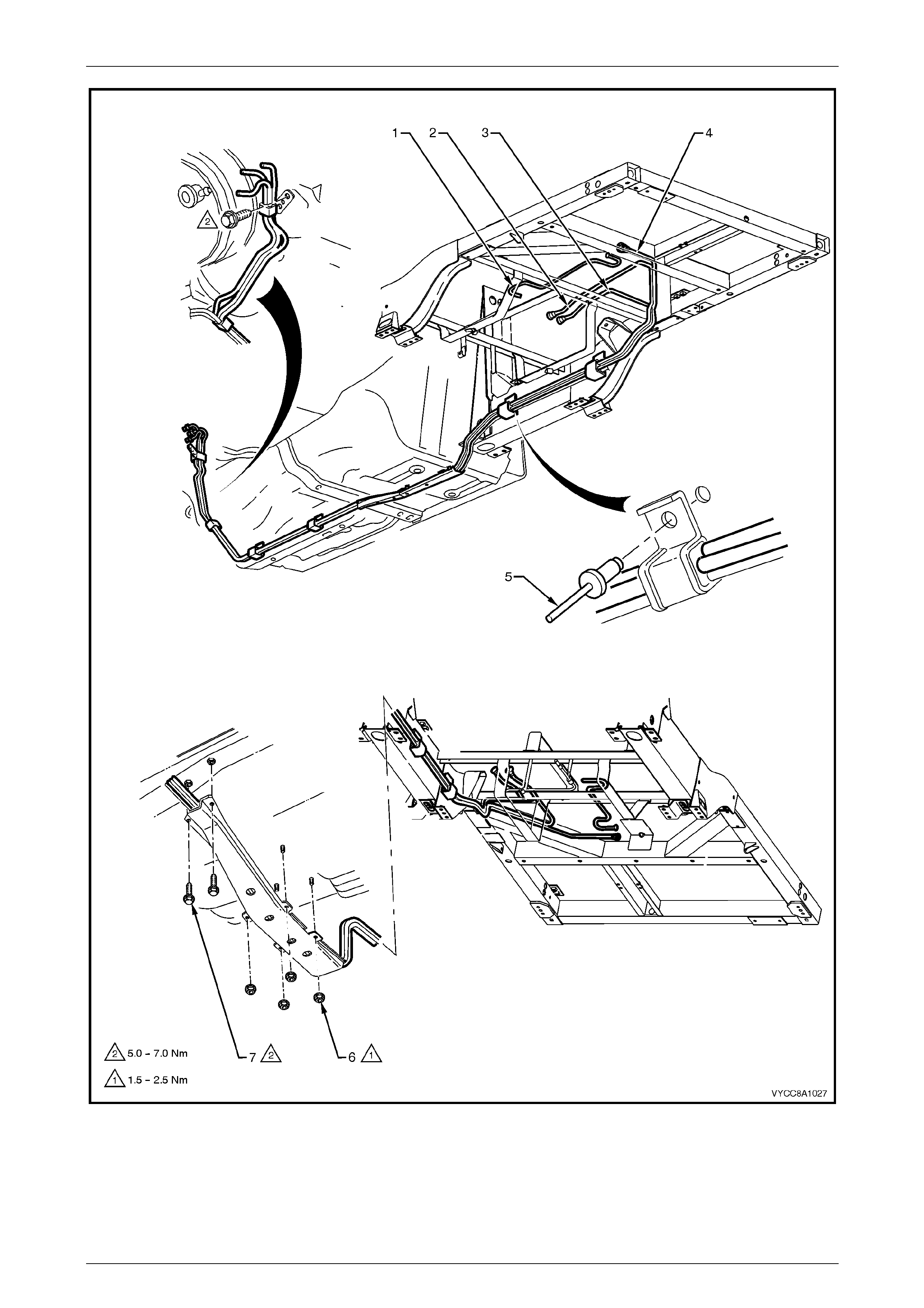
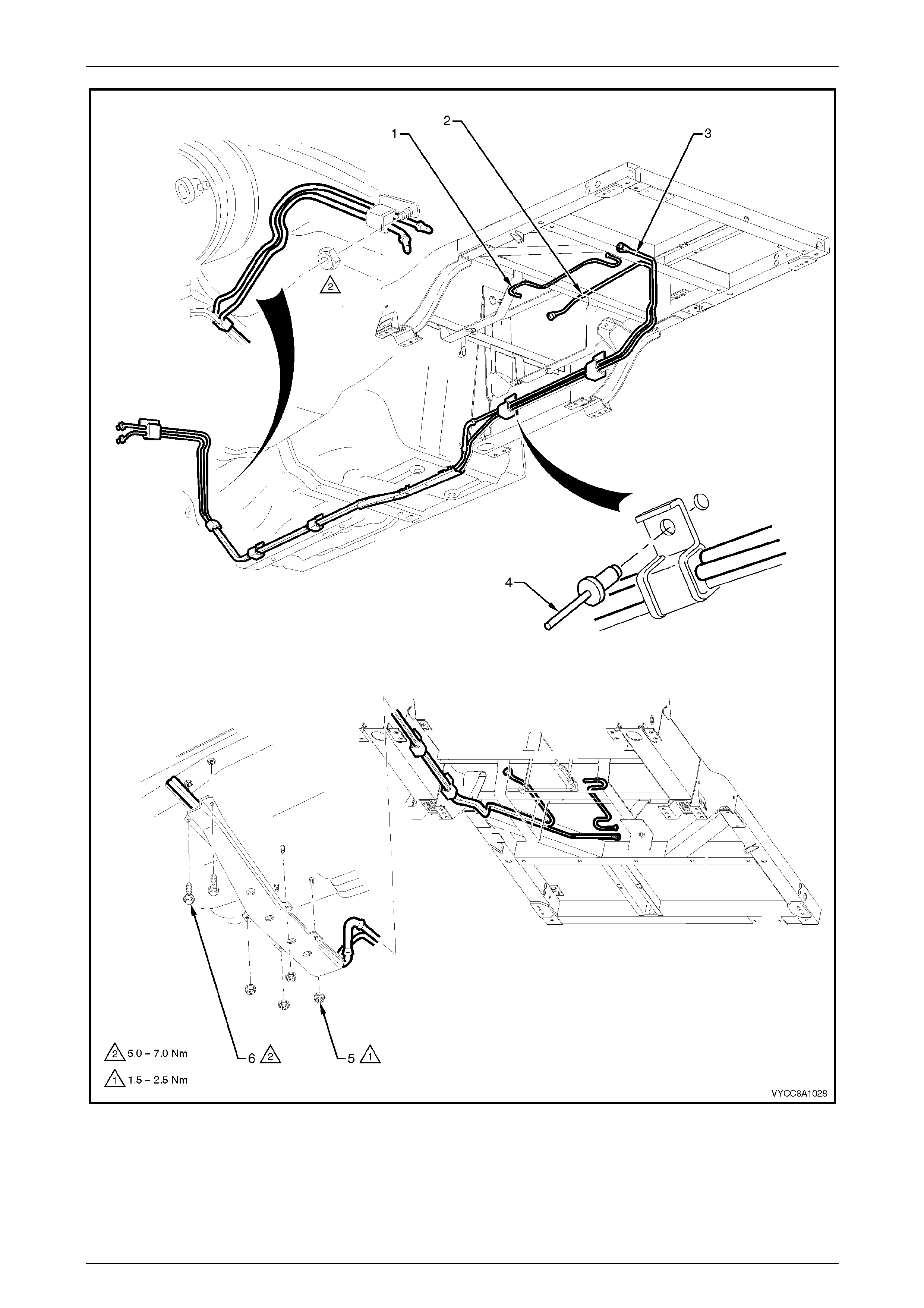
2.12 Fuel Pipe Arrangement
V6 Engine
Figure 8A1 – 71 illustrates the fuel pipe layout and location of other items relating to the fuel tank in vehicles with the V6
engine. For the fuel pipe arrangement for vehicles fitted with the LPG system, refer to Section 8A2 – LPG System in
this service information.
Fuel Tank Page 8A1–56
Page 8A1–56
Figure 8A1 – 71
Legend
1 Fuel Tank Vent Line
2 Fuel Feed Line
3 Fuel Return Line
4 Fuel Vapour Canister Purge Line
5 Fuel Line Bracket B l i nd Ri vet
6 Stone Guard S ecuring Nut (4 places)
7 Stone Guard S ecuring Bolt (2 pl aces)
Fuel Tank Page 8A1–57
Page 8A1–57
NOTE
For V6 engines, use special tool AU533 to
remove the fuel feed line (1) and fuel return
line (2) quick-connect fittings, refer to MY 2003
VY and V2 Series Service Information,
Section 8A1 Fuel Tank, 2.10 Quick-connect
Fittings.
Figure 8A1 – 72
Legend
1 Fuel Feed Line
2 Fuel Return Line 3 Fuel Vapour Canis ter
4 Fuel Tank Vent Line 5 Fuel Vapour Canister Purge Line
GEN III V8 Engine
Figure 8A1 – 73 illustrates the fuel pipe layout and location of other items relating to the fuel tank in vehicles with
GEN III V8 engine. For the fuel pipe arrangement for vehicles fitted with the LPG system, refer to Section 8A2 – LPG
System in this service information.
Fuel Tank Page 8A1–58
Page 8A1–58
Figure 8A1 – 73
Legend
1 Fuel Tank Vent Line
2 Fuel Feed Line 3 Fuel Vapour Canister Purge Line
4 Fuel Line Bracket B l i nd Ri vet 5 Stone Guard S ecuring Nut (4 places)
6 Stone Guard S ecuring Bolt (2 pl aces)
Fuel Tank Page 8A1–59
Page 8A1–59
NOTE
For GEN III V8 engines use special tool AU533
to remove the fuel feed line (1) quick-connect
fitting, refer to MY 2003 VY and V2 Series
Service Information, Section 8A1 Fuel Tank,
2.10 Quick-connect Fittings.
Figure 8A1 – 74
Legend
1 Fuel Feed Line
2 Fuel Vapour Canis ter 3 Fuel Tank Vent Line
4 Fuel Vapour Canister Purge Line

Fuel Tank Page 8A1–60
Page 8A1–60
3 Specifications
Fuel Tank Capacity:
..................................................................................................................................68.5 litres
Fuel Tank Material:
..........................................................................'W'-type high density multi-layer polyethylene
Fuel Filler Location:
........................................................Attached to support bracket underneath right side of tray
Fuel Pump Type:
........................................................................................................................... Single turbine
Pressure Regulator Location:
V6 Engine .............................................................................................................. Engine bay
GEN III V8 Engine....................................................Modular fuel pump and sender assembly
Fuel Pump Location:
................................................................................................................................In fuel tank
Fuel Pump Regulated Pressure:
..................................................................................................................400 kPa (+/– 3 kPa)
Minimum Fuel Pump Flow Capacity (at Regulated Pressure):
............................................................................................................2.95 L/min @ 13.5 volts
Fuel Pump Current Draw (Steady State at Regulated Pressure):
................................................................................................................11.0 Amps maximum
O-rings:
Pressure regulator (P/N 195306–0010)................................................................4.25 mm i.d.
Pressure regulator holder — top (P/N 195506–0150) ..........................................7.52 mm i.d.
Pressure regulator holder — bottom (P/N 167529–0010) ......................................8.2 mm i.d.
Fuel pump outlet (P/N 167529–0010).....................................................................8.2 mm i.d.
Pressure regulator (P/N 195306–0110)................................................................15.4 mm i.d.

Fuel Tank Page 8A1–61
Page 8A1–61
4 Torque Wrench Specifications
Fuel Tank Support Straps..........................................................30.0 – 40.0 Nm
Fuel Tank Mounting Strap Nuts.................................................20.0 – 25.0 Nm
Support Bracket Backing Plate Attaching Screws.....................20.0 – 25.0 Nm
Fuel Filter Bracket Screw...............................................................5.0 – 8.0 Nm
Fuel Vapour Canister Mounting Nu t ..............................................2.0 – 5.0 Nm
Stone Guard Securing Nut.............................................................1.5 – 2.5 Nm
Stone Guard Securing Bolt............................................................5.0 – 7.0 Nm
Fuel Tank Page 8A1–62
Page 8A1–62
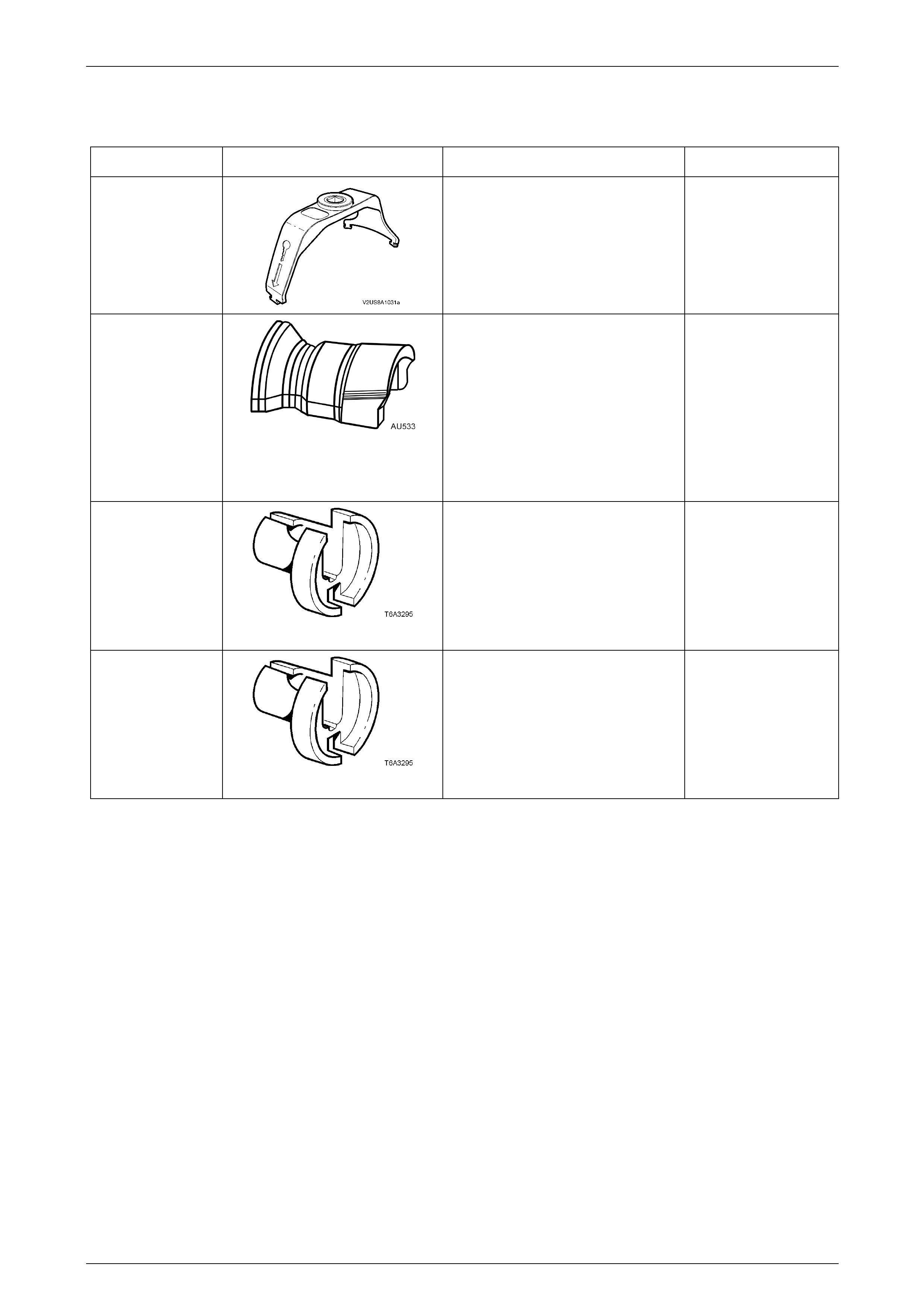
5 Special Tools
Tool Number Illustration Description Tool Classification
J45722
Modular fuel pump and sender
assembly lock ring remove and install
tool.
New release.
Mandatory
AU533
Quick-connect fitting release tool
Released in two sizes:
• Red for 5/16-inch fittings, and
• Blue for 3/8-inch fittings.
Commercially available under
P/N AUSP45.
Previously released.
Desirable
7370
Quick-connect release tool —
5/16-inch
Used for releasing fuel hose quick
connects at the dash panel and fuel
rail connections, after the fuel system
has been depressurised.
Previously released.
Mandatory
7371
Quick-connect release tool —
3/8-inch
Used for releasing fuel hose quick
connects at the dash panel and fuel
rail connections, after the fuel system
has been depressurised.
Previously released.
Mandatory