
Exhaust System Page 8B-1
Page 8B-1
Section 8B
Exhaust System
IMPORTANT
Before performing any Service Operation or other procedure described in this Section, refer to Section 00
CAUTION AND NOTES for correct workshop practices with regard to safety and/or damage.
1 General Description............................................................................................................................... 3
1.1 Exhaust System Configurations...........................................................................................................................3
V6 Engine Exhaust System...................................................................................................................................3
GEN III V8 Engine Exhaust System.......................................................................................................................4
2 Service Operations - V6......................................................................................................................... 5
2.1 Service Notes .........................................................................................................................................................5
Catalytic Converter.................................................................................................................................................5
Oxygen Sensors.....................................................................................................................................................5
2.2 Exhaust System......................................................................................................................................................6
2.3 Complete Exhaust System Assembly...................................................................................................................7
Remove ...................................................................................................................................................................7
Reinstall..................................................................................................................................................................8
2.4 Rear Exhaust Assembly.........................................................................................................................................9
Remove ...................................................................................................................................................................9
Reinstall................................................................................................................................................................10
2.5 Intermediate Exhaust Assembly.........................................................................................................................11
Remove .................................................................................................................................................................11
Reinstall................................................................................................................................................................11
2.6 Front Exhaust Assembly.....................................................................................................................................12
Remove .................................................................................................................................................................12
Reinstall................................................................................................................................................................13
2.7 Tightening Sequence...........................................................................................................................................14
3 Service Operations – GEN III V8......................................................................................................... 15
3.1 Service Notes .......................................................................................................................................................15
Catalytic Converter...............................................................................................................................................15
Oxygen Sensors...................................................................................................................................................15
3.2 Exhaust System....................................................................................................................................................16
3.3 Complete Exhaust System Assembly.................................................................................................................17
Remove .................................................................................................................................................................17
Reinstall................................................................................................................................................................19
3.4 Rear Exhaust Assembly.......................................................................................................................................20
Remove .................................................................................................................................................................20
Reinstall................................................................................................................................................................20
3.5 Intermediate Exhaust Assembly.........................................................................................................................21
Remove .................................................................................................................................................................21
Reinstall................................................................................................................................................................22
3.6 Front Exhaust Assemblies..................................................................................................................................23
Remove .................................................................................................................................................................23
Reinstall................................................................................................................................................................25
3.7 Tightening Sequence...........................................................................................................................................26

Exhaust System Page 8B-2
Page 8B-2
4 Service Operations – Tailpipe Hanger Bracket................................................................................. 28
Remove .................................................................................................................................................................28
Reinstall................................................................................................................................................................28
5 Service Operations – Exhaust System Heat Shields........................................................................ 29
5.1 Service Notes .......................................................................................................................................................29
5.2 Heat Shield – Intermediate Muffler .....................................................................................................................30
Remove .................................................................................................................................................................30
Reinstall................................................................................................................................................................30
5.3 Butyl Reflective Foil Insulators...........................................................................................................................31
Remove .................................................................................................................................................................31
Reinstall................................................................................................................................................................31
6 Exhaust System Clearances............................................................................................................... 32
7 Exhaust System Diagnosis................................................................................................................. 37
8 Specifications....................................................................................................................................... 38
9 Torque Wrench Specifications........................................................................................................... 39
Exhaust System Page 8B-3
Page 8B-3
1 General Description
This Section contains the service information for VY Cab Chassis Vehicles. For information that is not contained in this
Section, refer to Section 8B Exhaust System, in the MY 2003 VY and V2 Series Service Information. The major features
of each system are indicated below:
• For vehicles fitted with the V6 engine, a single catalytic converter, intermediate muffler and rear muffler is used.
• For vehicles fitted with the GEN III V8 engine, dual catalytic converters, dual intermediate mufflers and a single
rear muffler is used.
• The front exhaust systems for these vehicles are similar to those used on V6 and GEN III V8 MY 2003 VY vehicles
respectively.
1.1 Exhaust System Configurations
V6 Engine Exhaust System
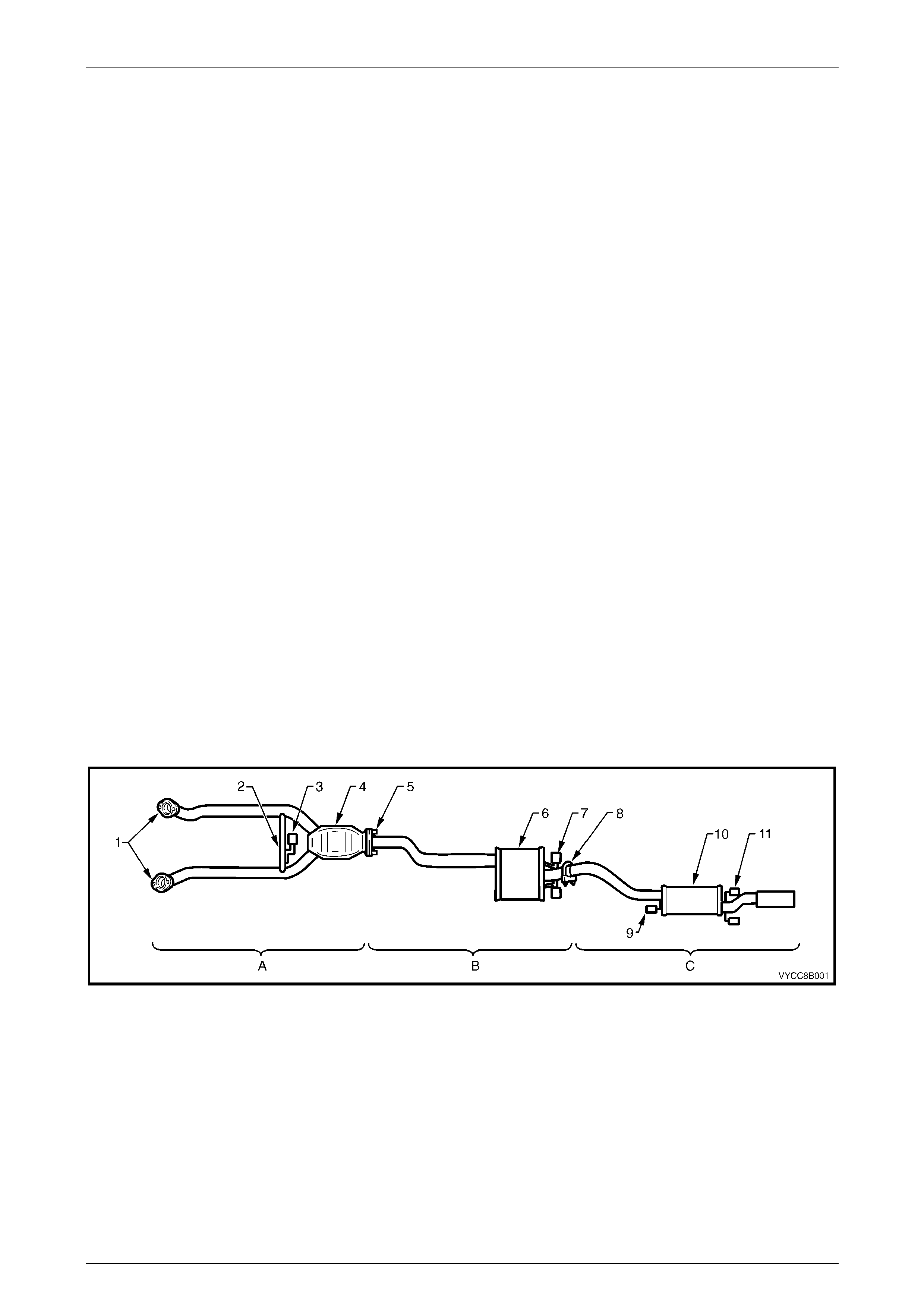
Refer to Figure 8B – 1 for the following.
The V6 engine exhaust manifolds are connected to a pair of stainless steel front pipes, by flanged joints (1). The
exhaust system features a single, three way catalytic converter (4), which forms a welded junction point for each of the
front exhaust pipes. A brace (2) and hanger peg assembly is welded across both of the front engine pipes.
A flanged joint (5) with an internal sealing ring is used to join the catalytic converter to the intermediate exhaust pipe.
The flange mating faces are held together by two spring loaded bolts. The intermediate exhaust assembly is joined onto
the rear exhaust assembly with a slip joint and U-bolt clamp (8), located behind the rear axle, before the rear muffler (9).
The front exhaust assembly is supported through a support rubber (3) attached to a hanger connected to the
transmission extension housing and to a peg welded to the cross brace (2).
The intermediate exhaust assembly is supported through two support rubbers (7) that are attached to hangers welded to
the vehicle underbody and to pegs welded to the intermediate muffler (6).
The rear exhaust assembly is supported through three support rubbers (9 and 11), connected to hangers welded to the
vehicle underbody and to pegs welded along the pipes. One is located along the rear exhaust pipe close to the
upstream face of the rear muffler and two are attached to the tailpipe, close to the downstream face of the rear muffler.
The support rubbers are a common part for all locations and are secured by retainer clips at the intermediate and rear
body hangers. Flanged pegs are used at other locations.
Figure 8B – 1
Legend
A Front Exhaust Assem bl y
B Intermediate E xhaust Assembly
C Rear Exhaust Assembly
1 Manifold to Front P i pe Fl ange
2 Front Exhaust Brace
3 Front Support Rubber
4 Catalytic Converter
5 Catalytic Converter to Intermediate Pi pe
Flange Joint
6 Intermediate Muffler
7 Intermediate Muff l e r S upport Rubbers
8 Intermediate t o Rear P i pe Slip Joi nt and
U–clamp
9 Rear Muffler Support Rubber
10 Rear Muffler
11 Rear Support Rubbers
Exhaust System Page 8B-4
Page 8B-4
GEN III V8 Engine Exhaust System
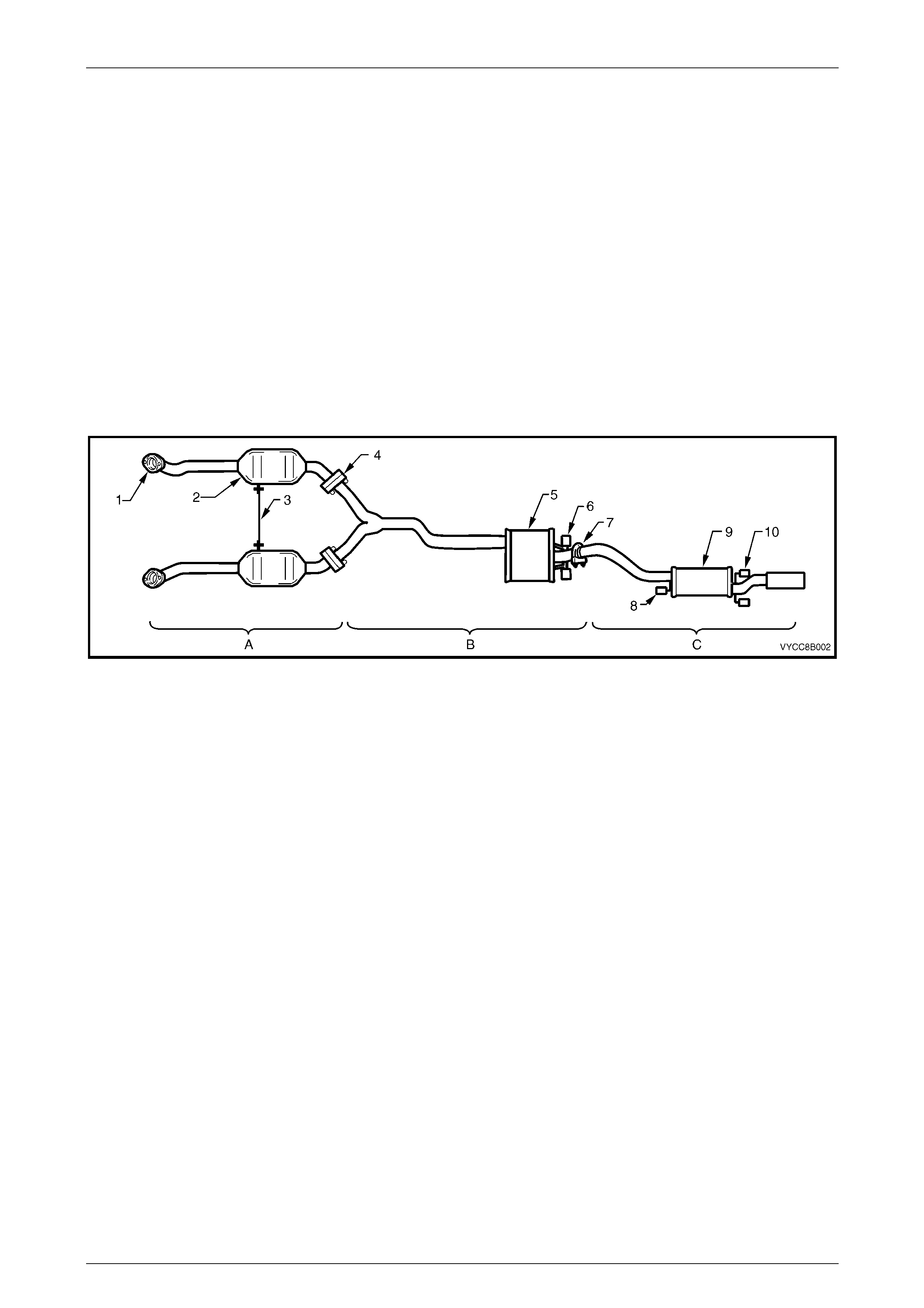
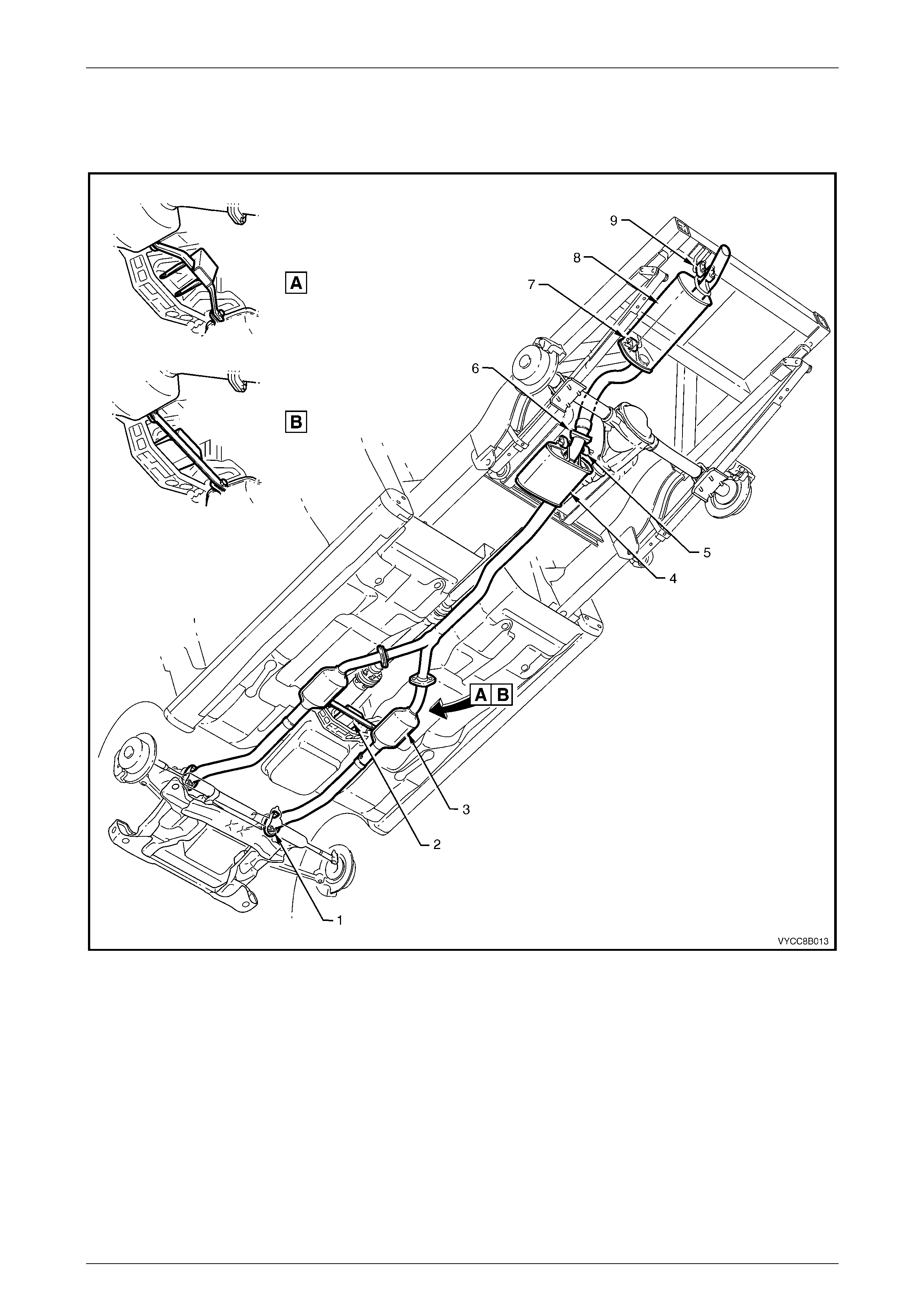
Refer to Figure 8B – 2 for the following.
The GEN III V8 engine exhaust manifolds are connected to a pair of dual wall stainless steel front pipes, through flanged
joints (1). Each front pipe runs into a catalytic converter (2) and then extends down stream of the converter to connect
with the intermediate exhaust assembly through flanged, gasketed joints (4). The intermediate pipes merge into a single
pipe that extends down stream to the intermediate muffler (5). A pipe extends from the rear of the muffler and joins onto
the rear exhaust assembly through a slip joint and U-bolt clamp (7). The rear pipe runs into the rear muffler (9), which
features a single exhaust tail pipe.
The intermediate exhaust assembly is supported at the intermediate muffler through a pair of support rubbers (6)
attached to hangers welded to the vehicle underbody and to pegs welded to the rear of the muffler. The rear exhaust
assembly is supported through three support rubbers, connected to hangers welded to the vehicle underbody and to
pegs welded along the pipes. One is located along the rear exhaust pipe close to the upstream face of the rear muffler
and two are attached to the tailpipe, close to the downstream face of the rear muffler.
For further support, a bracket (3) is bolted between each converter and is fastened to the transmission extension
housing. This support configuration is different for automatic and manual transmissions.
The support rubbers are a common part for all locations and are secured by retainer clips at the intermediate and rear
body hangers. Flanged pegs are used at other locations.
Figure 8B – 2
Legend
A Front Exhaust Assem bl y
B Intermediate E xhaust Assembly
C Rear Exhaust Assembly
1 Manifold to Front P i pe Fl ange
2 Catalytic Converter
3 Front Exhaust Assem bl y B race
4 Front to Int ermediate Pipe Flange Joint
5 Intermediate Muffler
6 Intermediate Muff l e r S upport Rubbers
7 Intermediate t o Rear P i pe Slip Joi nt and
U-bolt Clamp
8 Rear Muffler Support Rubber
9 Rear Muffler
10 Rear Muffler Support Rubbers
Exhaust System Page 8B-5
Page 8B-5
2 Service Operations - V6
2.1 Service Notes
When installing any exhaust system component, care must be taken to install each component in the correct
relationship to the other. Ensure that correct assembly, installation, tightening sequence, tightening torque and
clearances for the system involved are observed. When exhaust system service work is required, refer to the various
illustrations and instructions provided in this section.
NOTE
The incorrect assembly of exhaust system
components can frequently be the cause of
rattles and ‘booms' due to incorrect alignment or
clearance of body or suspension parts. Ensure
that the correct tightening sequence is observed
upon installation of exhaust system components.
Catalytic Converter
The catalytic converter is serviced as part of the complete front exhaust pipe assembly only.
NOTE
If removing or replacing the front exhaust
assembly, always check the sealing ring for
damage and replace if necessary.
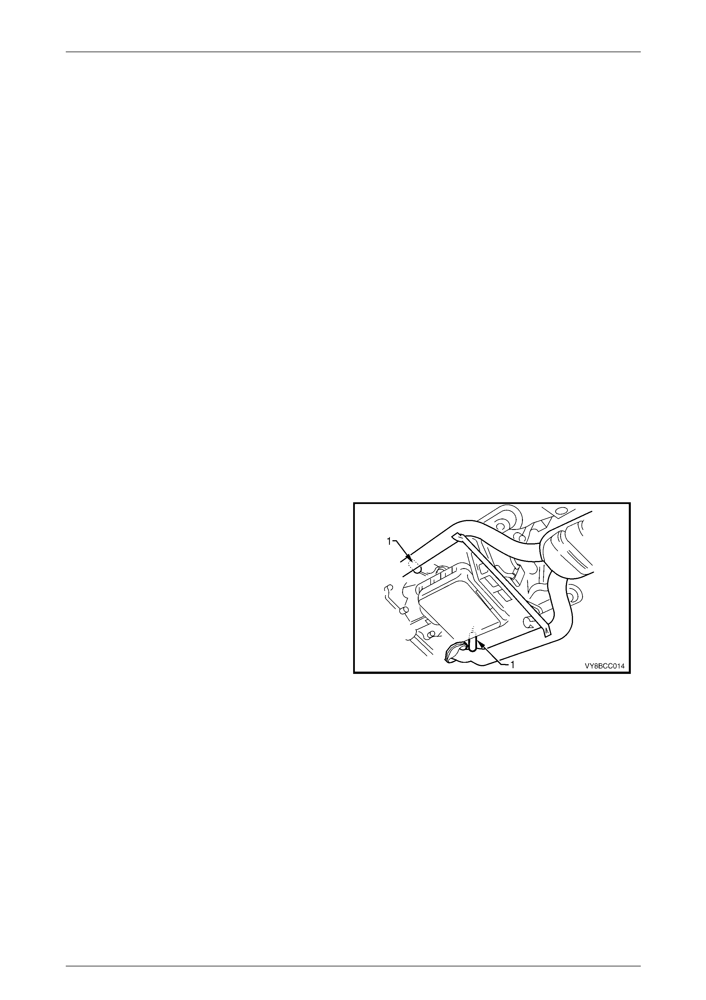
Oxygen Sensors
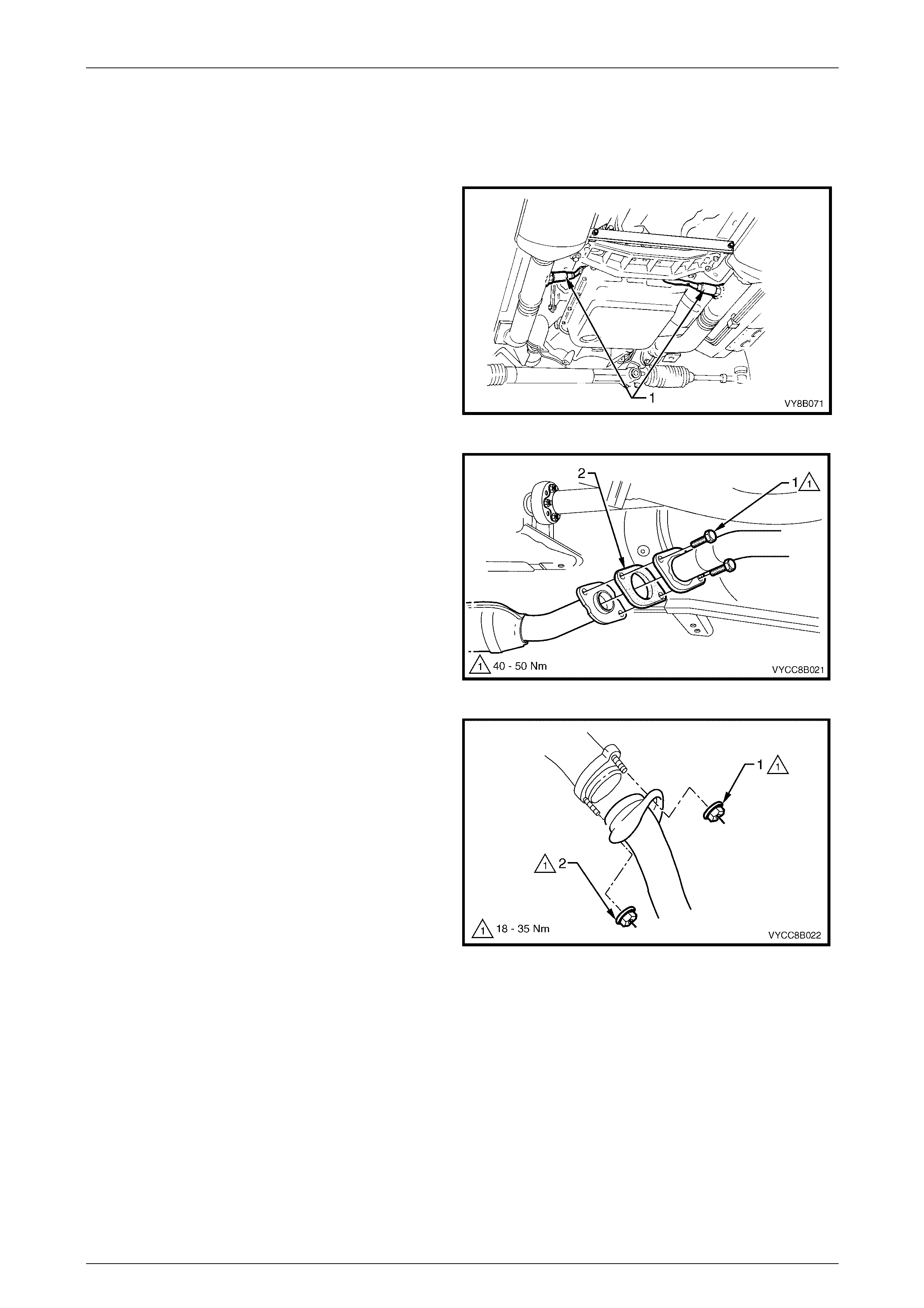
When removing the front exhaust pipes, it is necessary to
disconnect the wiring harness connectors from each of the
two oxygen sensors (1).
For oxygen sensor replacement, refer to Section 6C1-3,
2.6 Oxygen Sensor in the MY 2003 VY and V2 Series
Service Information.
Figure 8B – 3
Exhaust System Page 8B-6
Page 8B-6
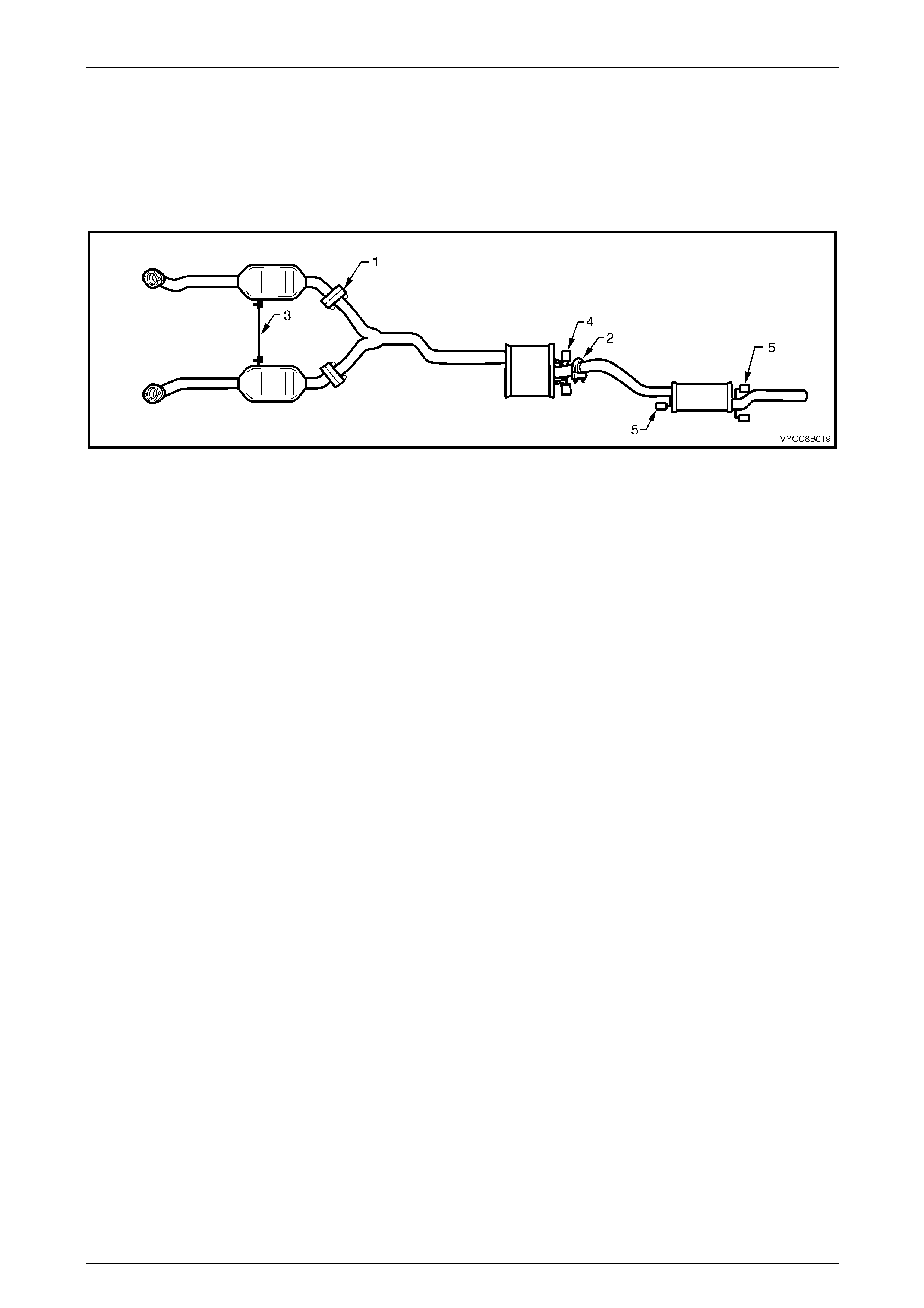
2.2 Exhaust System
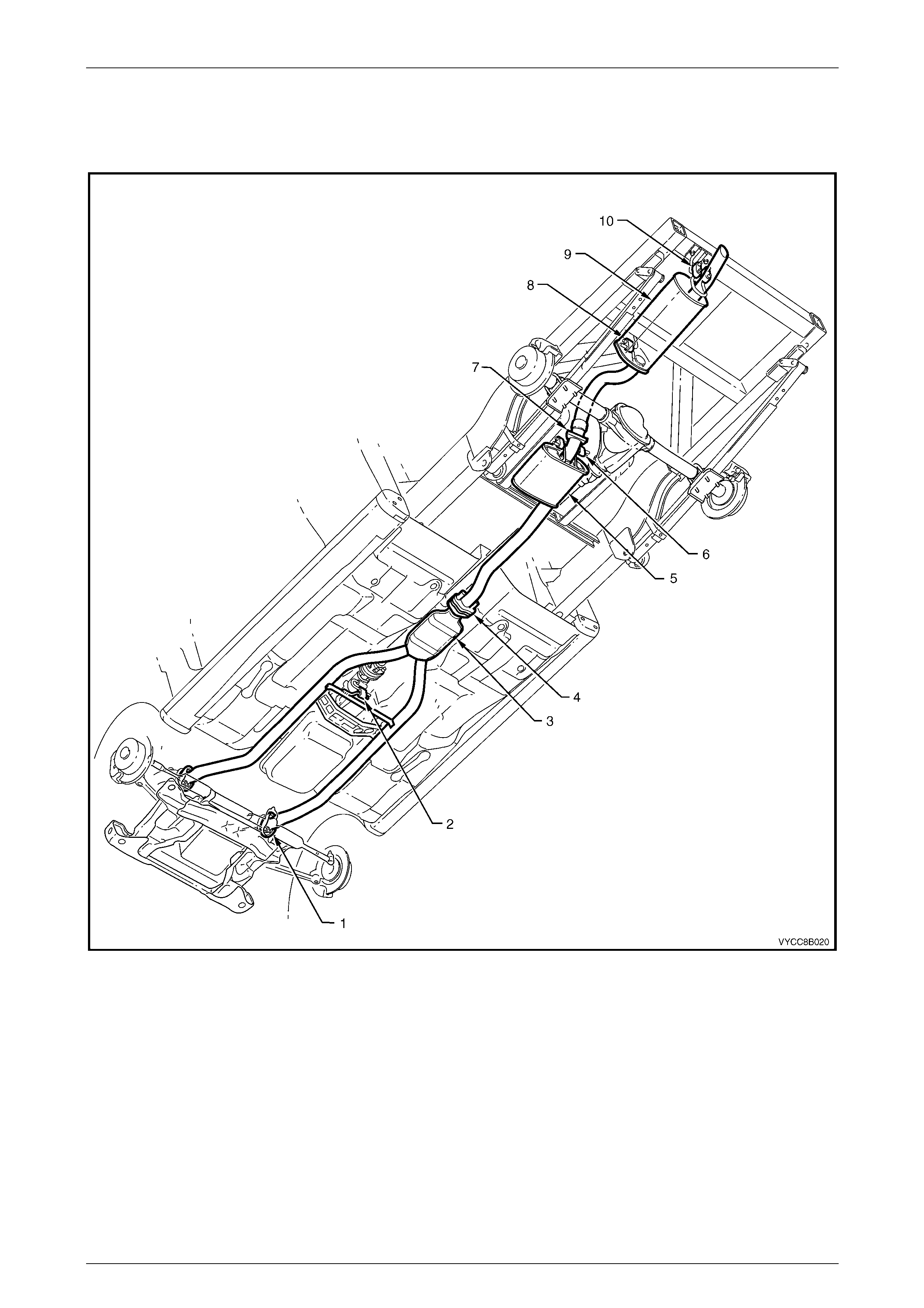
Figure 8B – 4 illustrates the exhaust system configuration used with the V6 engine.
Figure 8B – 4
Legend
1 Manifold to Front P i pe Fl ange
2 Front Exhaust Brace and Rubber Support
3 Catalytic converter
4 Flange Joint
5 Intermediate Muffler
6 Intermediate Muff l er Support Rubbers
7 Intermediate t o Rear P i pe Slip Joi nt and U-clamp
8 Rear Muffler Support Rubber
9 Rear Muffler
10 Rear Exhaust Support Rubbers
Exhaust System Page 8B-7
Page 8B-7
2.3 Complete Exhaust System Assembly
Remove
1 Remove the rear exhaust assembly, refer to 2.4 Rear Exhaust Assembly in this Section.
2 Disconnect the wiring harness connectors from each
of the two oxygen sensors (1).
Figure 8B – 5
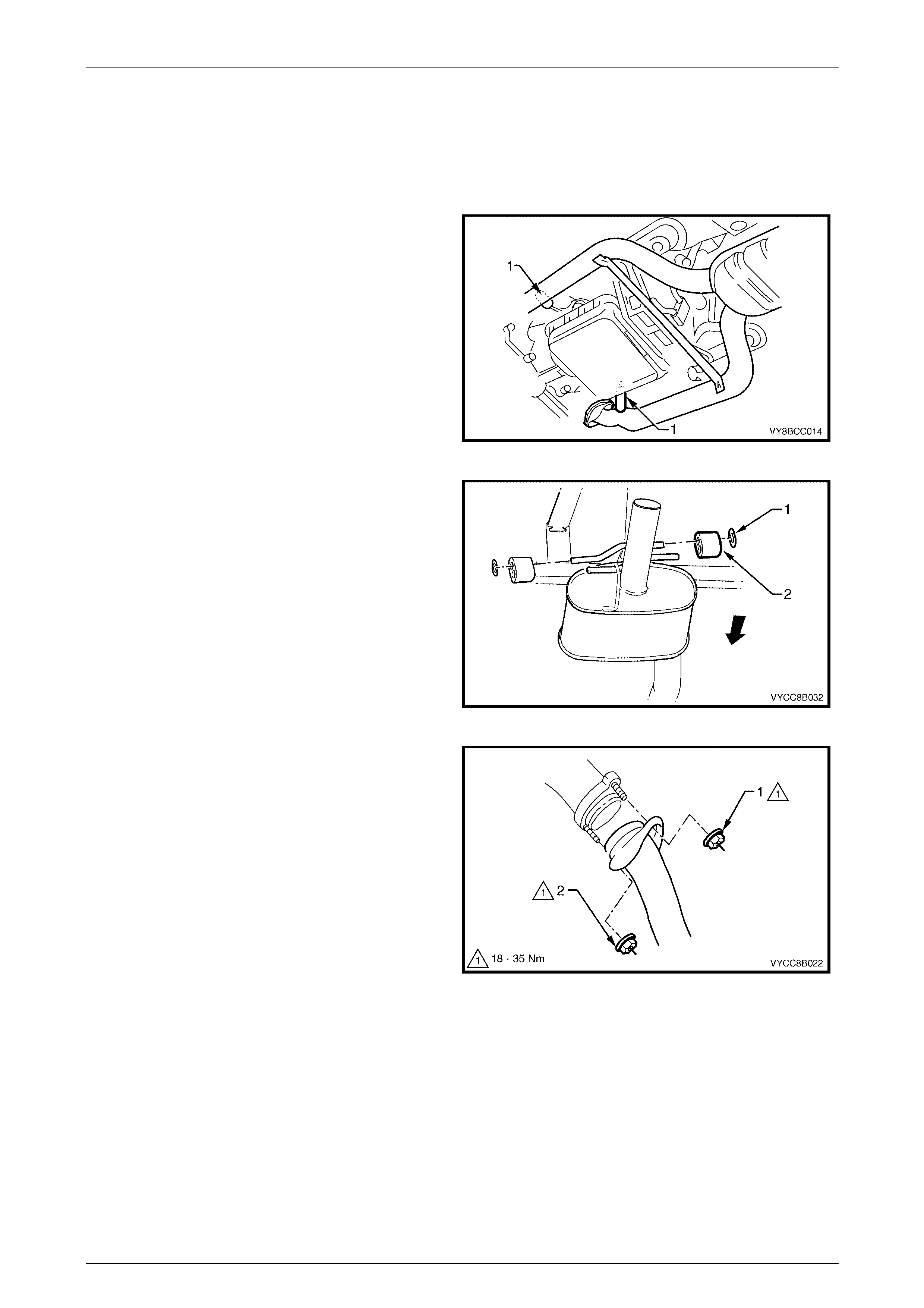
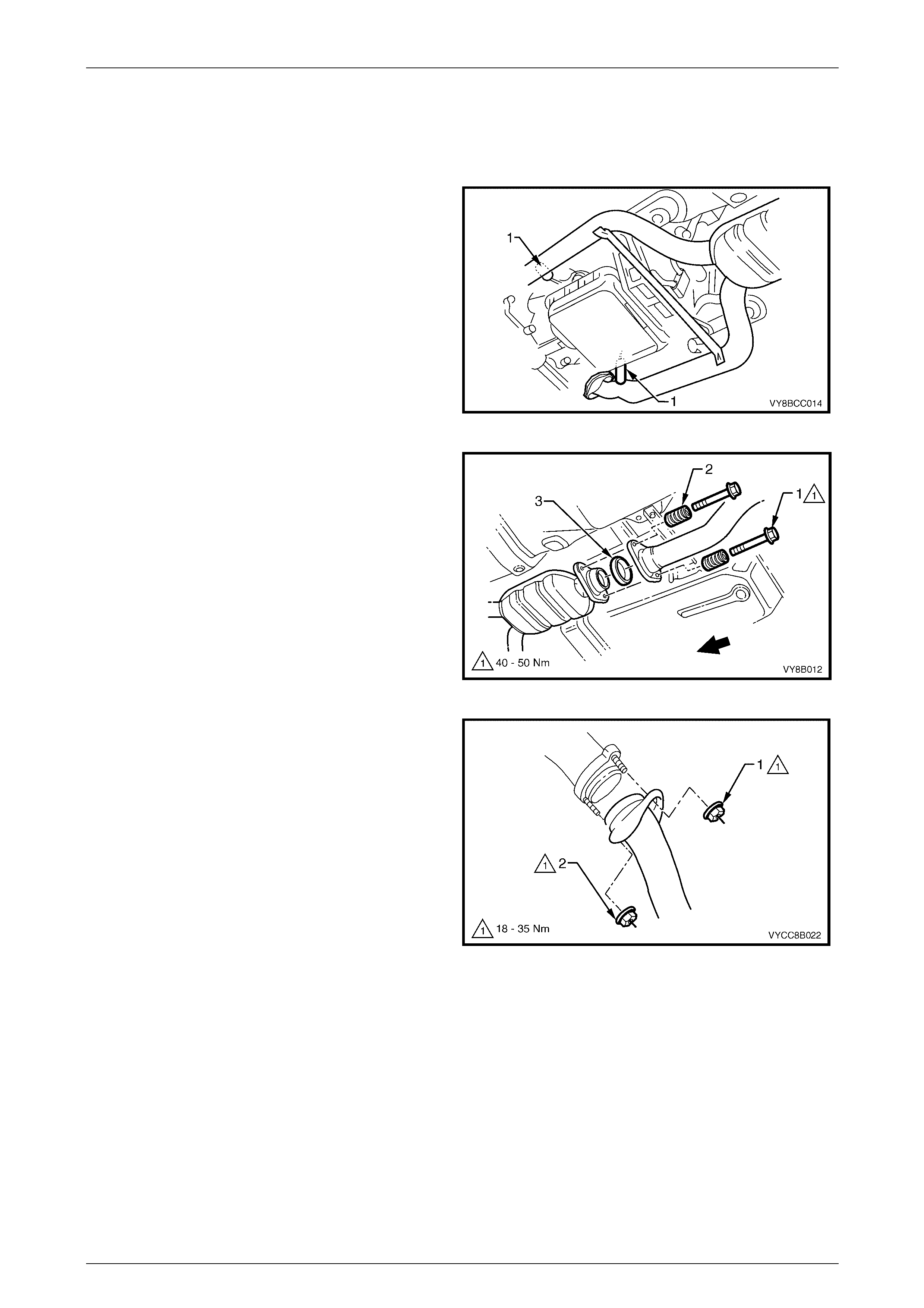
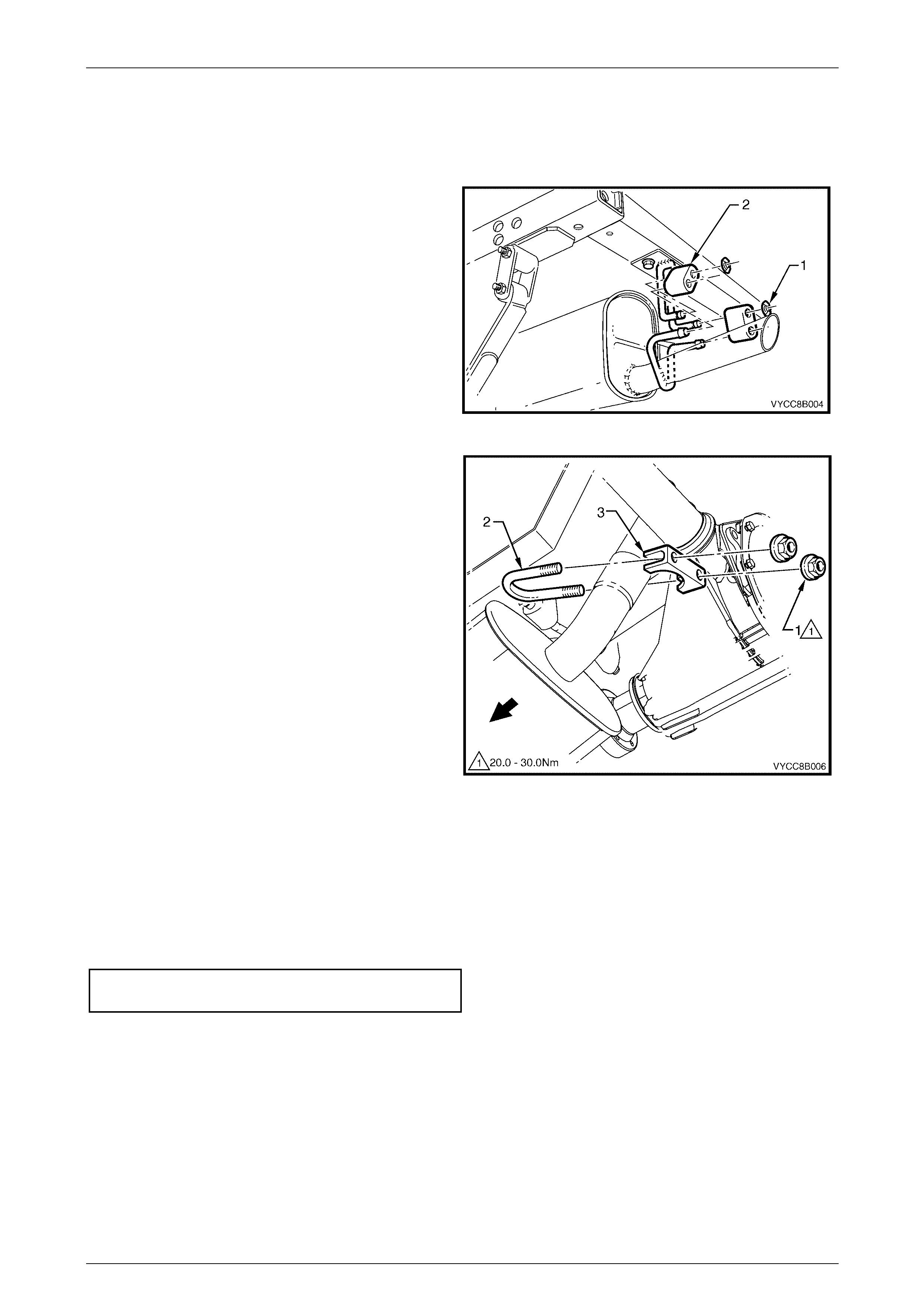
3 Support the exhaust system and disconnect the
intermediate muffler from the support hangers by
removing the two retainer clips (1) and the two
support rubbers (2).
Figure 8B – 6
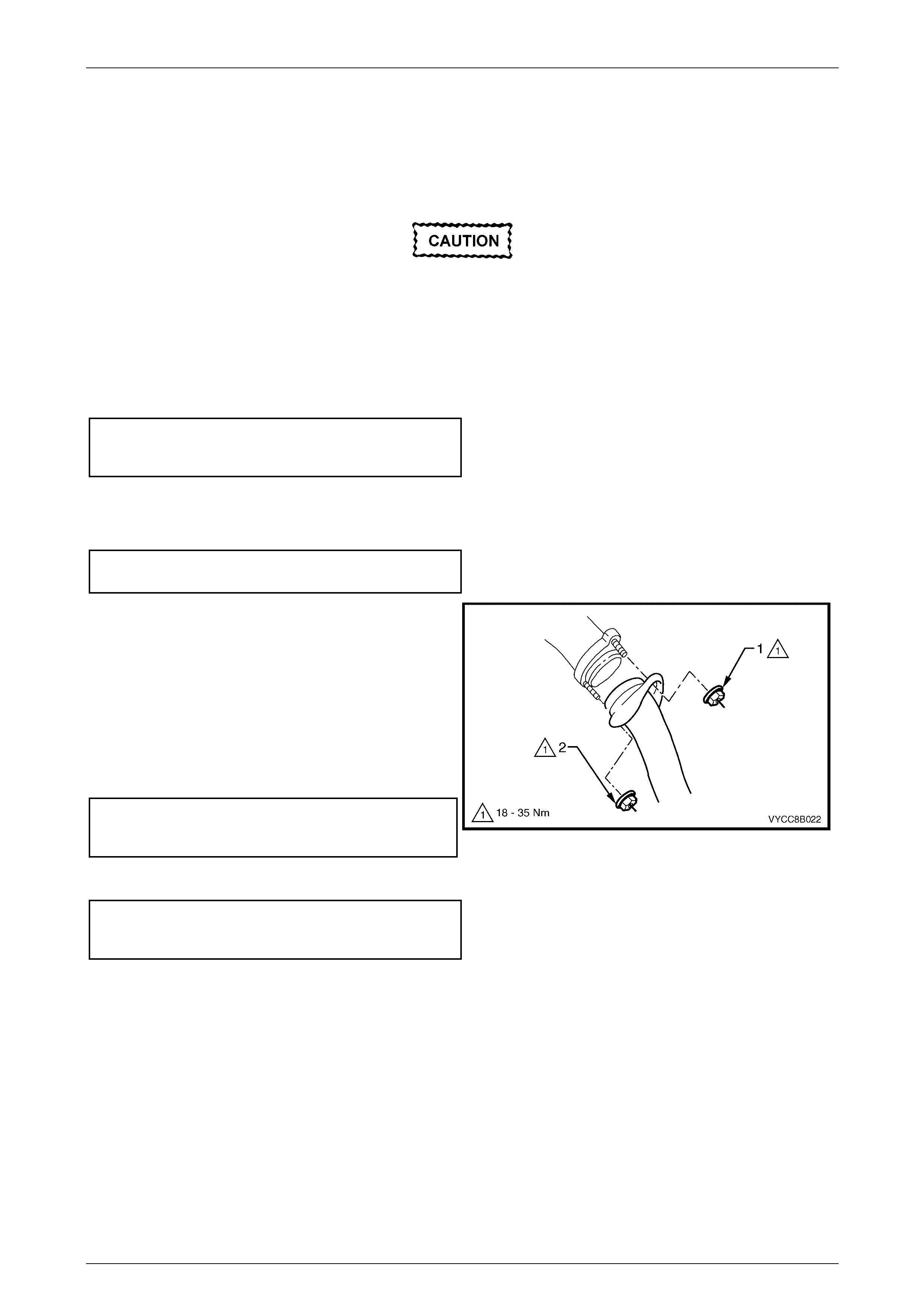
4 Support the exhaust system and remove the
upper (1) and lower (2) fastening nuts from the
exhaust manifold to exhaust pipe flange studs on
both sides.
Figure 8B – 7
Exhaust System Page 8B-8
Page 8B-8
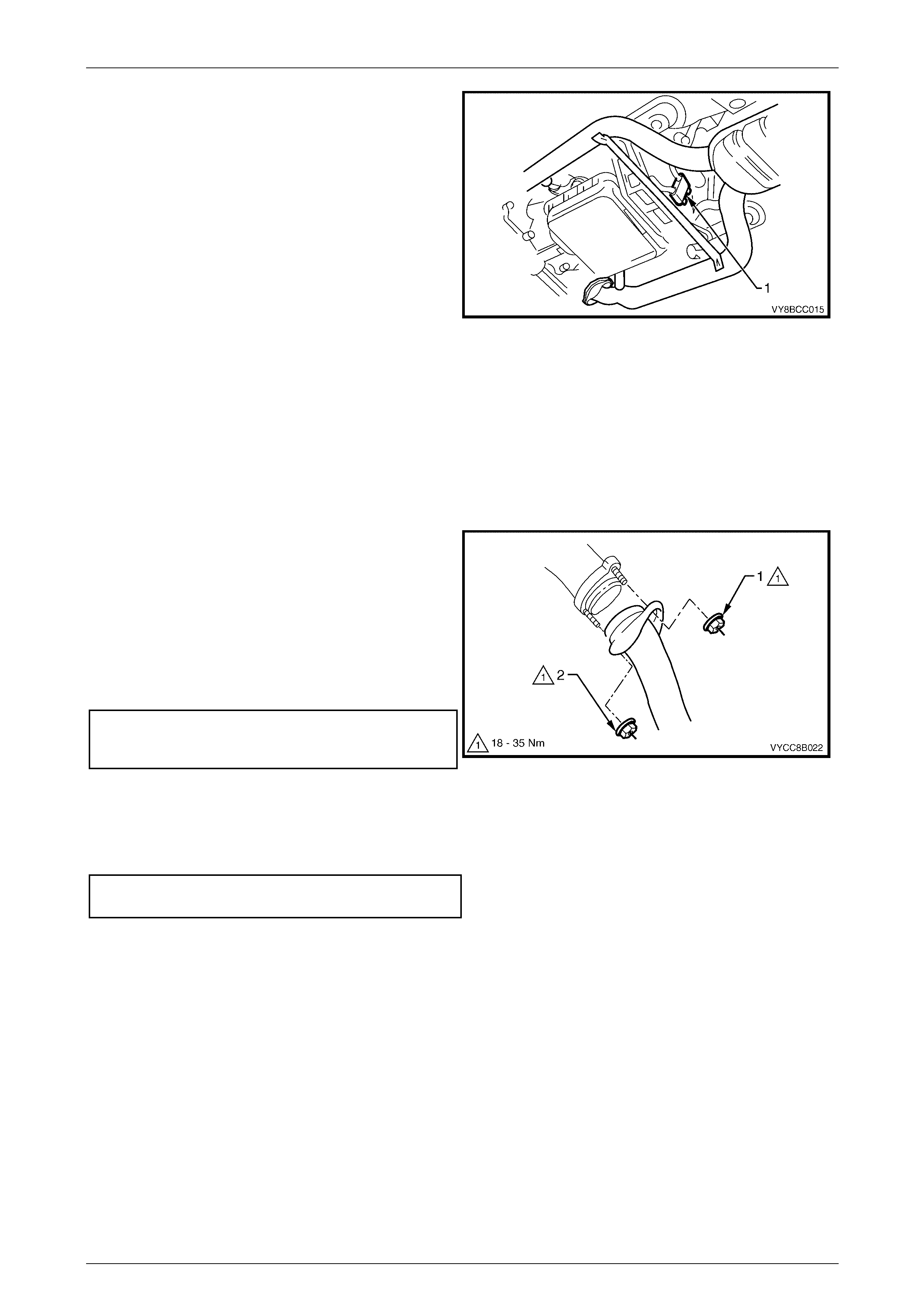
5 Disconnect the front exhaust assembly by removing
the support rubber (1) from the peg welded to the
exhaust pipe brace.
6 Carefully lower and remove the exhaust assembly
from the vehicle, taking care not to damage the
exhaust gas oxygen sensors.
Figure 8B – 8
Reinstall
Installation of the complete exhaust system is the reverse of the removal procedure, noting the following points:
1 Support the exhaust system at all times.
2 Clean the threads of the flange studs, bolts and nuts with a suitable cleaning solvent.
3 Apply a high temperature anti-seize compound to the exhaust manifold to exhaust pipe flange studs and align the
front pipe flange over the studs.
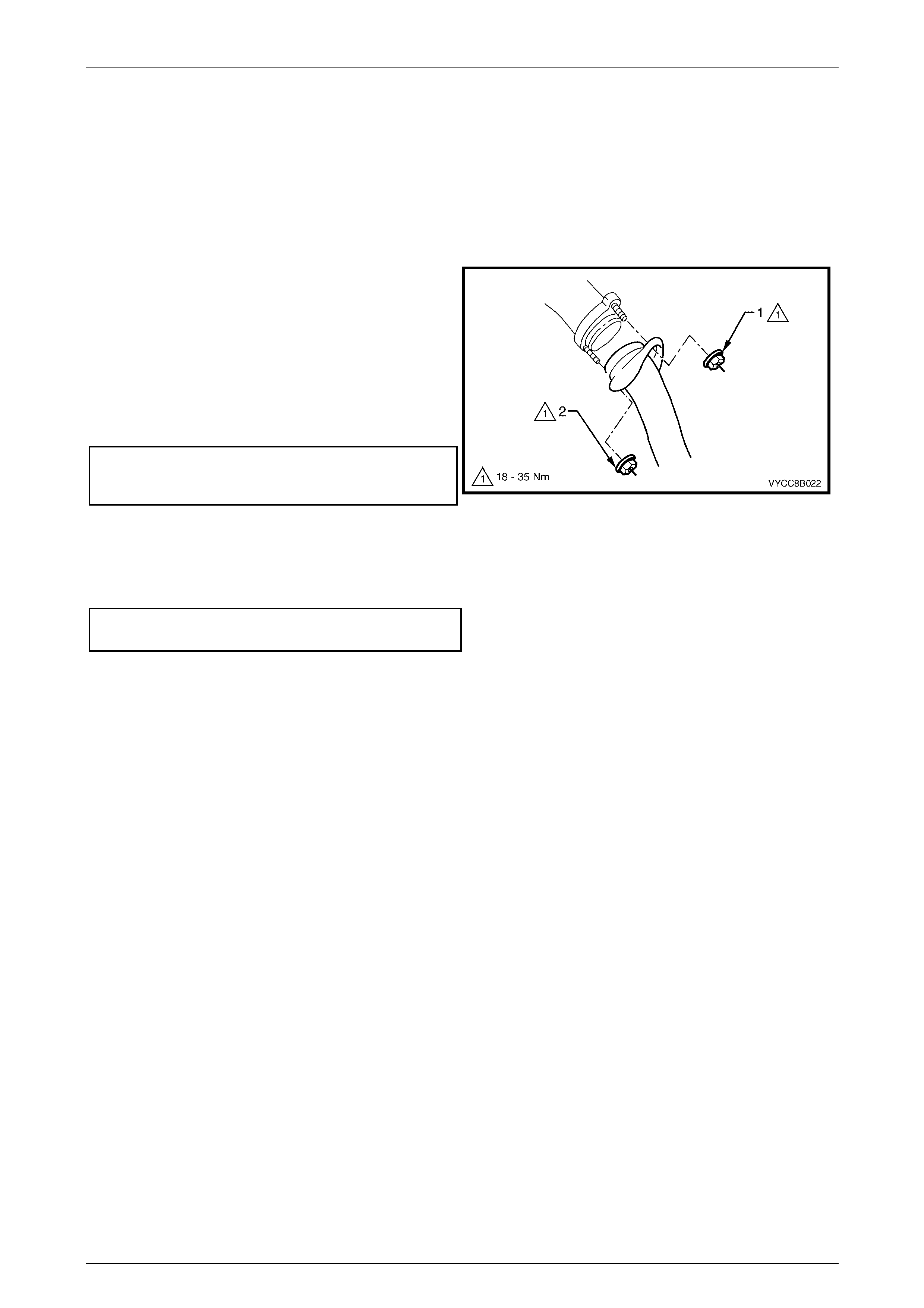
4 Hand tighten the upper fastening nut (1) to the stud
on both sides.
5 Hand tighten the lower fastening nut (2) to the stud
on both sides.
6 Tighten each nut so that approximately equal
amounts of thread are showing.
7 Tighten the upper then lower fastening nuts to the
specified torque.
Exhaust manifold to front
pipe flange stud attaching nut
torque specification..................................... 18 – 35 Nm
Figure 8B – 9
8 Upon installation of the rear exhaust pipe assembly, ensure that the rear exhaust pipe slides unobstructed into the
intermediate exhaust pipe slip joint, and that the alignment key is positioned in the slip joint groove.
9 Tighten the U-bolt securing nuts to the specified torque.
U-bolt clamp assembly securing
nuts torque specification .............................. 20 – 30 Nm
8 Ensure all support rubbers are under load.
9 Ensure that correct body clearances are maintained throughout the full exhaust system. Refer to
6 Exhaust System Clearances in this Section.
NOTE
If steps 8 or 9 are not achieved, refer to
2.7 Tightening Sequence in this Section.
10 Connect the wiring harness connectors for each of the two oxygen sensors.
Exhaust System Page 8B-9
Page 8B-9
2.4 Rear Exhaust Assembly
Remove
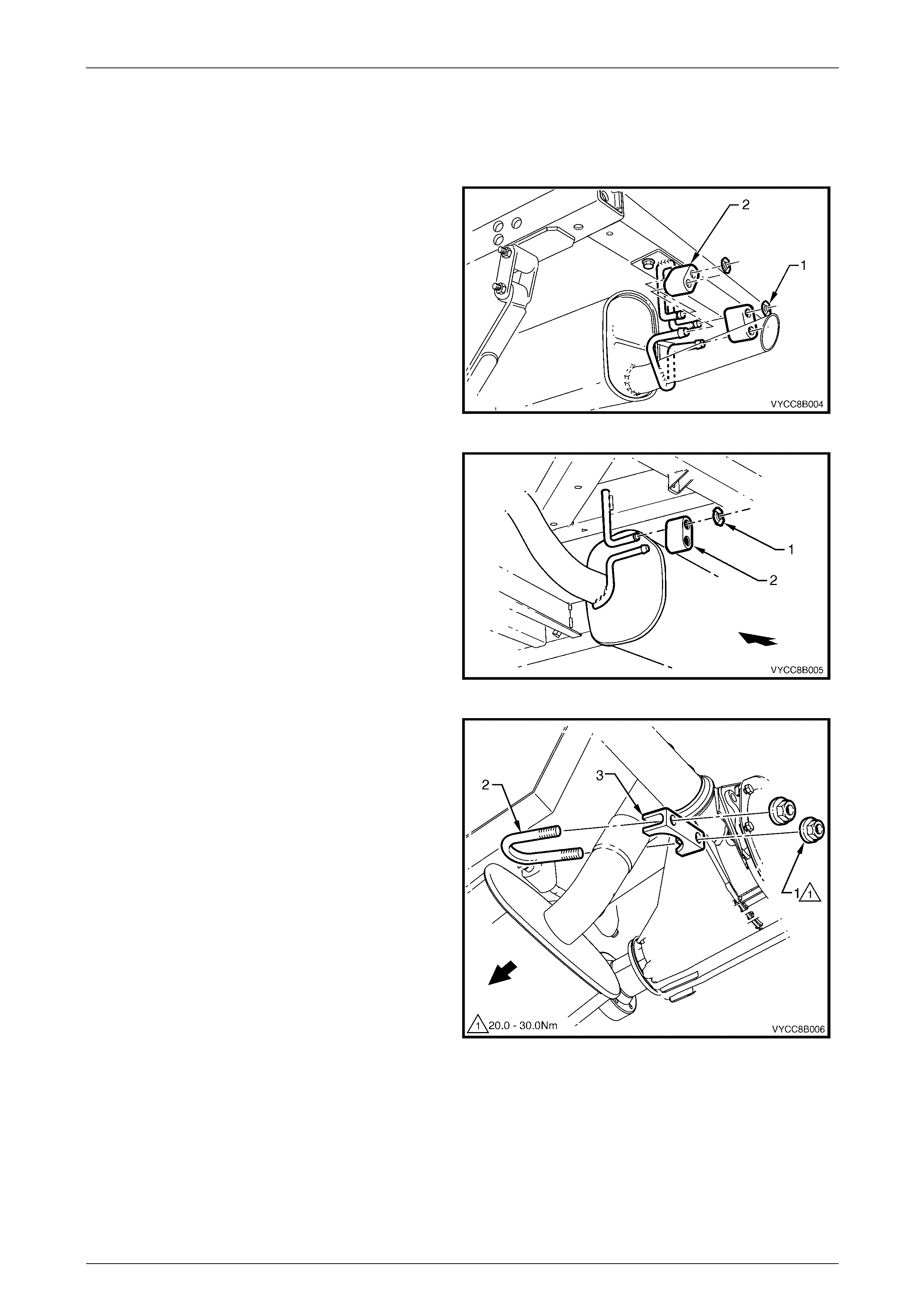
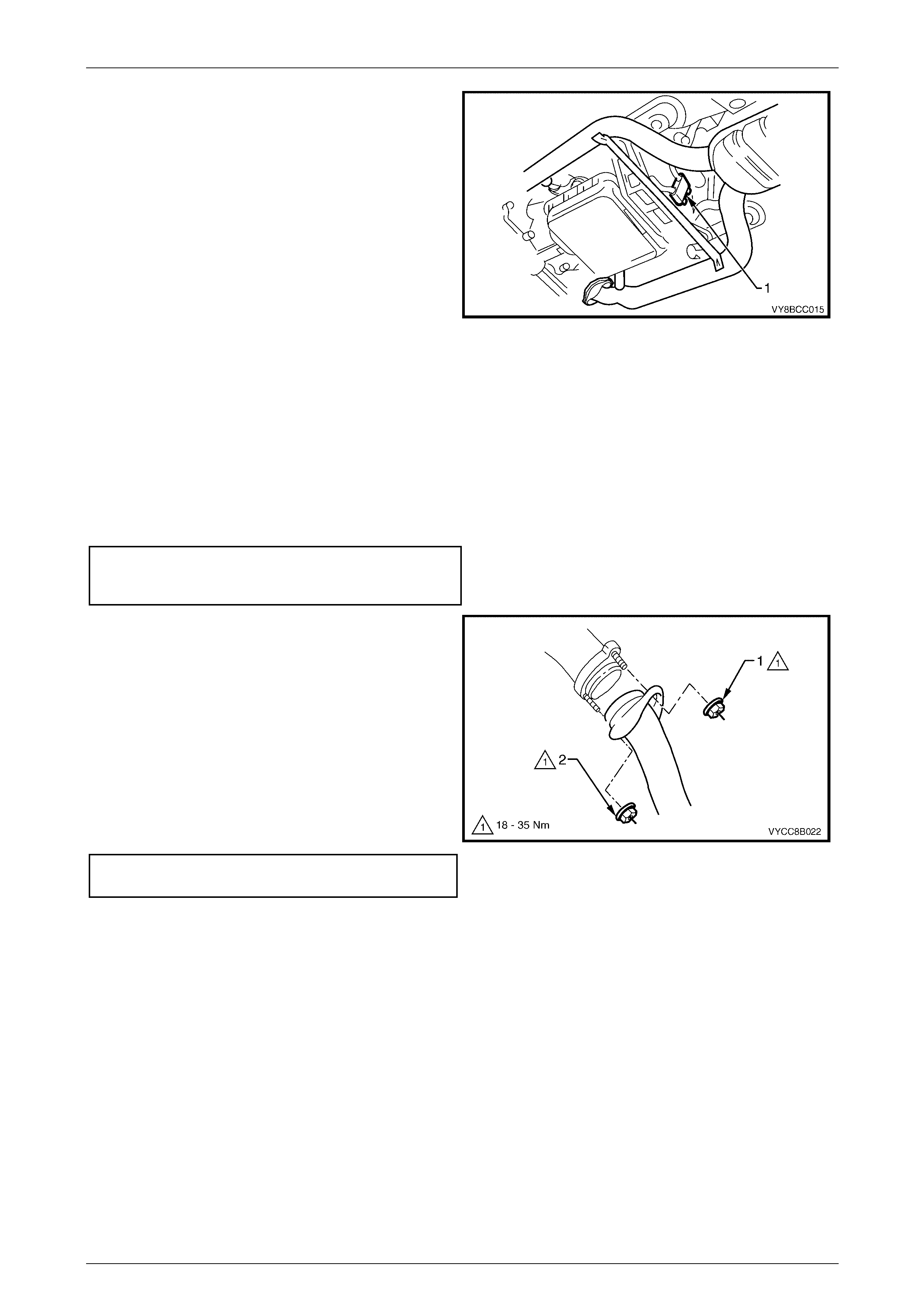
1 Remove the two support hanger retainer clips (1) and
the two support rubbers (2) from the tailpipe support
hangers.
Figure 8B – 10
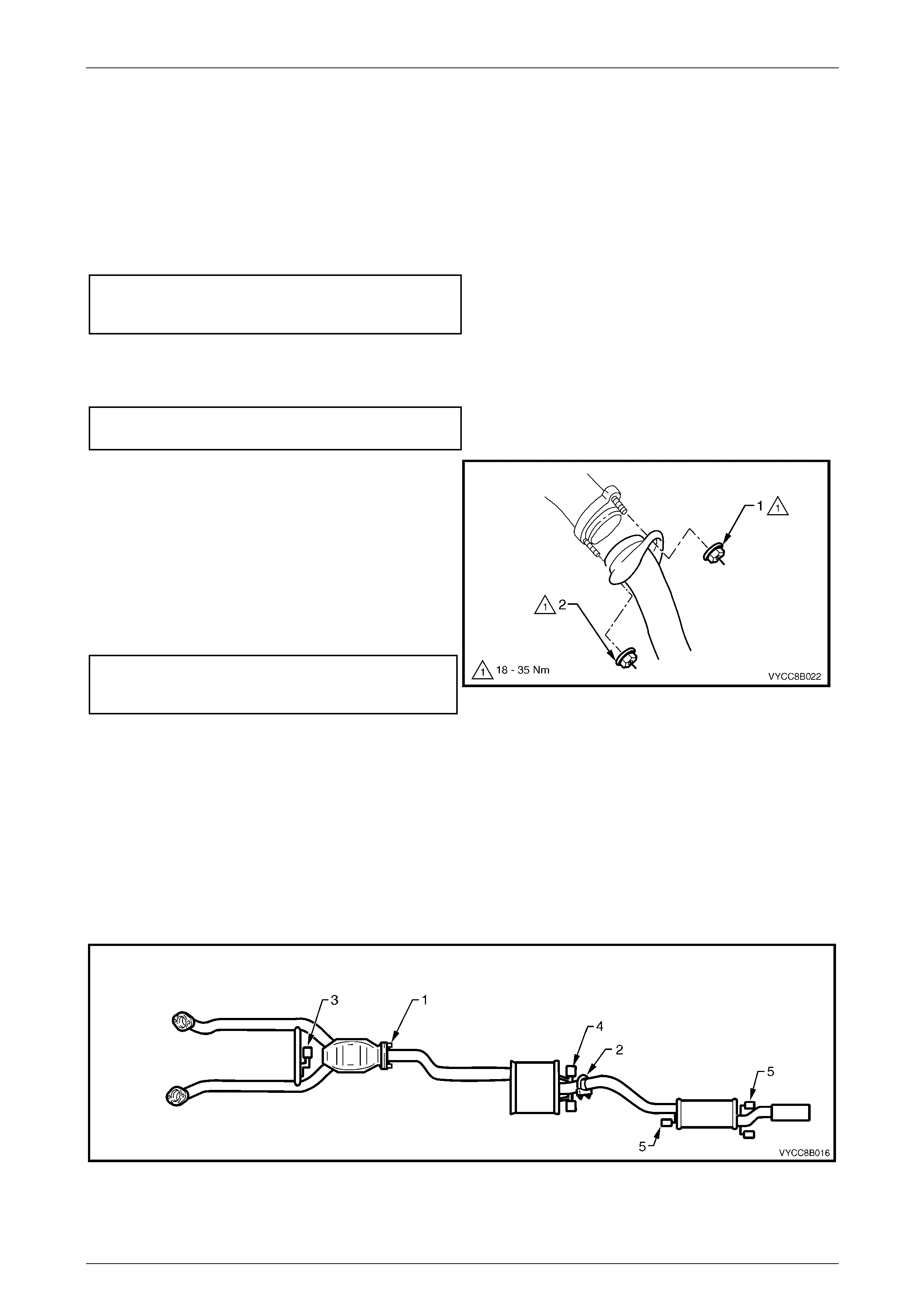
2 Remove the support hanger retainer clip (1) and the
support rubber (2) from the upstream side of the rear
muffler assembly.
Figure 8B – 11
3 Remove the two retaining nuts (1) and the rear
muffler U-bolt (2) and clamp (3) from along the
intermediate exhaust pipe to rear muffler exhaust
pipe slip joint.
4 Carefully slide the rear exhaust pipe out of the
intermediate exhaust pipe end slip joint and remove
the rear exhaust assembly.
Figure 8B – 12

Exhaust System Page 8B-10
Page 8B-10
Reinstall
Installation of the rear exhaust assembly is the reverse of the removal procedure, noting the following:
1 Ensure that the rear exhaust pipe slides unobstructed into the intermediate exhaust pipe slip joint, and that the
alignment key is positioned in the slip joint groove.
2 Tighten the U-bolt securing nuts to the specified torque.
U-bolt clamp assembly securing
nut torque specification................................20 – 30 Nm
3 Ensure all support rubbers are under load.
4 Ensure that correct body clearances are maintained throughout the full exhaust system. Refer to
6 Exhaust System Clearances in this Section.
NOTE
If steps 3 or 4 are not achieved, refer to
2.7 Tightening Sequence in this Section.
5 Connect the wiring harness connectors for each of the two oxygen sensors.
Exhaust System Page 8B-11
Page 8B-11
2.5 Intermediate Exhaust Assembly
Remove
1 Remove the rear muffler. Refer to 2.4 Rear Exhaust Assembly in this Section.
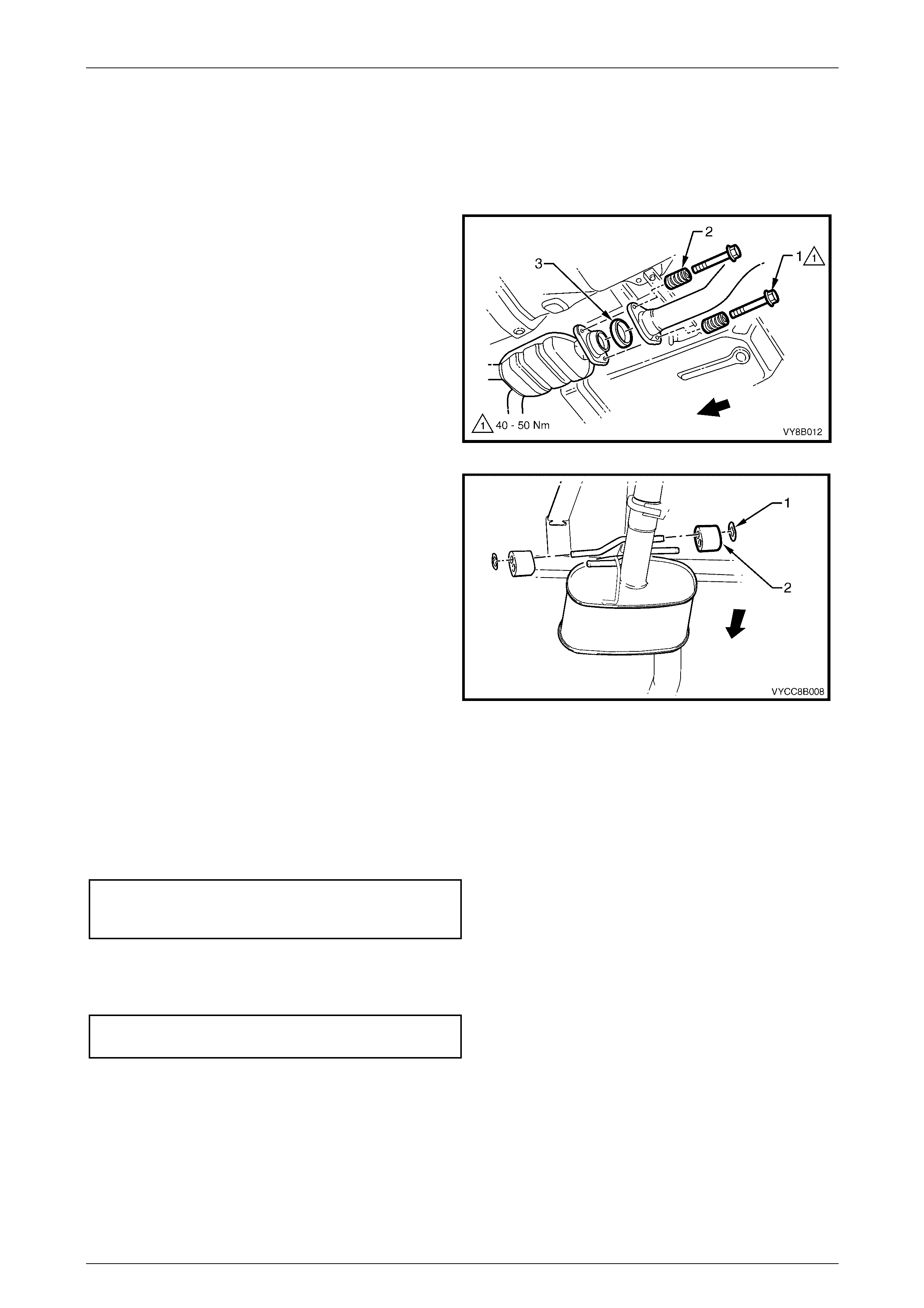
2 Support the intermediate exhaust assembly and
remove the two stepped fastening bolts (1) and
springs (2) from the intermediate to front exhaust
assembly flange joint.
3 Separate the intermediate exhaust assembly from the
front exhaust assembly and remove the sealing
ring (3) from within the flange joint.
Figure 8B – 13
4 Remove the two retainer clips (1) and support
rubbers (2) from the support hangers and remove the
intermediate exhaust assembly.
Figure 8B – 14
Reinstall
Installation of the intermediate exhaust assembly is the reverse of the removal procedure, noting the following:
1 Check flange sealing ring for damage and replace where necessary.
2 Clean threads of flange bolts with a suitable cleaning solvent.
3 Tighten the intermediate to front exhaust assembly flange stepped fastening bolts to the specified torque.
Intermediate to front exhaust assembly
flange stepped fastening bolt
torque specification......................................40 – 50 Nm
4 Upon installation of the rear exhaust pipe assembly, ensure that the rear exhaust pipe slides unobstructed into the
intermediate exhaust pipe slip joint, and that the alignment key is positioned in the slip joint groove.
5 Tighten the U-bolt securing nuts to the specified torque.
U-bolt clamp assembly securing
nut torque specification................................20 – 30 Nm
6 Ensure all support rubbers are under load.
7 Ensure that correct body clearances are maintained throughout the full exhaust system. Refer to
6 Exhaust System Clearances in this Section.
NOTE
If steps 6 or 7 are not achieved, refer to
2.7 Tightening Sequence in this Section.
8 Connect the wiring harness connectors for each of the two oxygen sensors.
Exhaust System Page 8B-12
Page 8B-12
2.6 Front Exhaust Assembly
Remove
1 Disconnect the wiring harness connectors from each
of the two oxygen sensors (1).
Figure 8B – 15
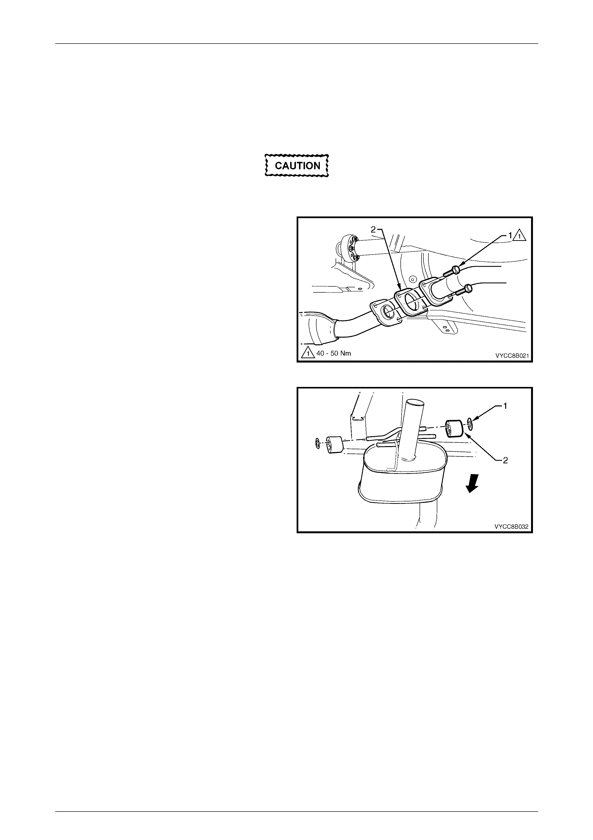
2 Support the intermediate exhaust assembly and
remove the two stepped fastening bolts (1) and
springs (2) from the intermediate to front exhaust
assembly flange joint.
3 Separate the intermediate exhaust assembly and
remove the sealing ring (3) from within the flange
joint.
Figure 8B – 16
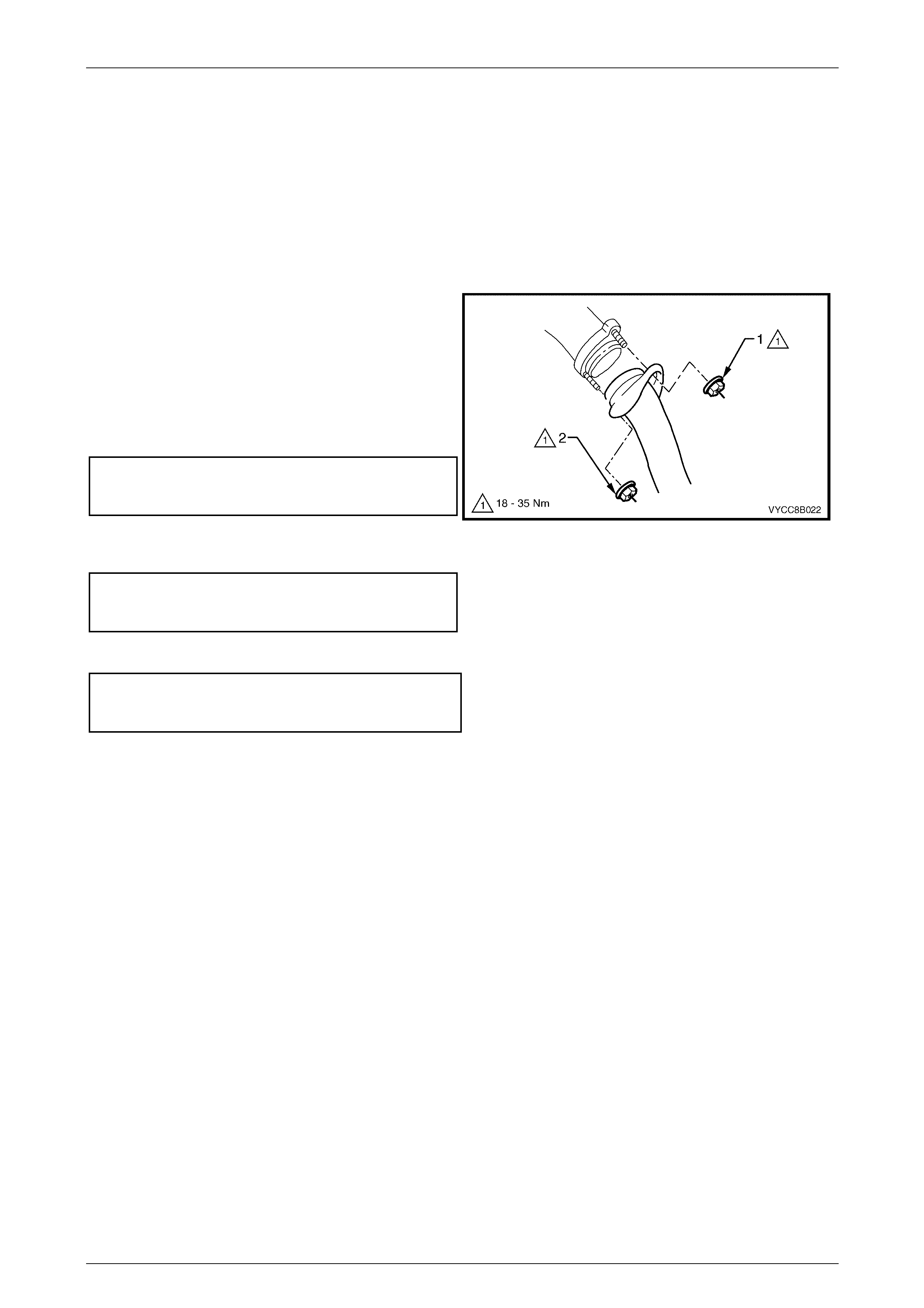
4 Support the front exhaust assembly and remove the
upper (1) and lower (2) fastening nuts from the
exhaust manifold to exhaust pipe flange studs on
both sides.
Figure 8B – 17
Exhaust System Page 8B-13
Page 8B-13
5 Disconnect the front exhaust assembly by removing
the support rubber (1) from the peg welded to the
exhaust pipe brace.
6 Carefully lower and remove the front exhaust
assembly from the vehicle, taking care not to damage
the exhaust gas oxygen sensor.
Figure 8B – 18
Reinstall
Installation of the front exhaust assembly is the reverse of the removal procedure, noting the following points:
1 Support the exhaust system at all times.
2 Clean threads of flange bolts and studs with a suitable cleaning solvent.
3 Check sealing ring for damage and replace where necessary.
4 Tighten the intermediate to front exhaust assembly flange stepped fastening bolts to the specified torque.
Intermediate to front exhaust assembly
flange stepped fastening bolt
torque specification......................................40 – 50 Nm
5 Apply a high temperature anti-seize compound to the
exhaust manifold to exhaust pipe flange studs and
align the front pipe flange over the studs.
6 Hand tighten the upper fastening nut (1) to the stud
on both sides.
7 Hand tighten the lower fastening nut (2) to the stud
on both sides.
8 Tighten the upper then lower fastening nuts so that
approximately equal amounts of thread are showing.
9 Tighten the upper then lower fastening nuts to the
specified torque.
Exhaust manifold to front pipe
flange fastening nut torque specification..... 18 – 35 Nm
Figure 8B – 19
10 Ensure all support rubbers are under load.
11 Ensure that correct body clearances are maintained throughout the full exhaust system. Refer to
6 Exhaust System Clearances.
NOTE
If steps 10 or 11 are not achieved, refer to
2.7 Tightening Sequence in this Section.
12 Connect the wiring harness connectors for each of the two oxygen sensors.
Exhaust System Page 8B-14
Page 8B-14
2.7 Tightening Sequence
This procedure is only to be performed if the exhaust system positioning is not to specification.
Refer to Figure 8B – 21 for the following.
Ensure that all fasteners mentioned in steps 1 to 6 below are loose before conducting this procedure.
1 Tighten the intermediate to front exhaust assembly flange fastening bolts (1) at the rear of the catalytic converter
to the specified torque.
Intermediate to front exhaust assembly
flange stepped fastening bolt
torque specification......................................40 – 50 Nm
2 Check that the rear exhaust pipe aligning key is seated within the intermediate exhaust pipe’s end slip joint groove.
Position the U-bolt clamp along the intermediate to rear slip joint and tighten the pair of fastening nuts (2) to the
specified torque.
U-bolt clamp assembly securing
nut torque specification................................20 – 30 Nm
3 Hand tighten the upper fastening nut (1) to the stud
on both sides.
4 Hand tighten the lower fastening nut (2) to the stud
on both sides.
5 Tighten the upper then lower fastening nuts (1 and 2)
on both sides so that approximately equal amounts of
thread are showing.
6 Tighten the upper then lower fastening nuts (1 and 2)
on both sides to the specified torque.
Exhaust manifold to front
pipe flange stud attaching nut
torque specification..................................... 18 – 35 Nm
Figure 8B – 20
7 Ensure that all six support rubbers (3, 4 and 5) are under load, refer to Figure 8B – 21. If this is not achieved,
loosen the respective joints in the reverse order to steps 1 to 6. Load the hangers and re-tighten in the sequence
described, from steps 1 to 6.
NOTE
The exhaust system should be self-aligning and
not require further adjustment, provided step 7 is
achieved. To ensure that correct clearances are
maintained throughout the complete exhaust
system, refer to 6 Exhaust System Clearances
for the correct values.
Figure 8B – 21
Exhaust System Page 8B-15
Page 8B-15
3 Service Operations – GEN III V8
3.1 Service Notes
When installing any exhaust system component, care must be taken to install each component in the correct
relationship to the other. Ensure that correct assembly, installation, tightening sequence, tightening torque and
clearance for the system involved is observed. When exhaust system service work is required, refer to the various
illustrations and instructions provided in this section.
NOTE
The incorrect assembly of exhaust system
components can frequently be the cause of
rattles and ‘booms' due to incorrect alignment or
clearance of body or suspension parts. Ensure
that the correct tightening sequence is observed
upon installation of exhaust system components.
Catalytic Converter
Catalytic converters are serviced as part of the complete front pipe assembly only.
NOTE
If removing or replacing the front exhaust
assembly, always check flange gaskets for
damage and replace if necessary.
Oxygen Sensors
When removing the front exhaust pipes, it is necessary to
disconnect the wiring harness connectors from each of the
two oxygen sensors (1).
For oxygen sensor replacement, refer to Section 6C3-3,
2.8 Heated Oxygen Sensors, in the MY 2003 VY and V2
Series Service Information.
Figure 8B – 22
Exhaust System Page 8B-16
Page 8B-16
3.2 Exhaust System
Figure 8B – 23 provides a reference to the location of relevant exhaust system removal and installation components.
Figure 8B – 23
Legend
A Transmission to Catalytic
Converter Mounting Bracket -
Manual Transmi ssion
B Transmission to Catalytic
Converter Mounting Bracket -
Automatic Transmission
1 Manifold to Front P i pe Fl ange Joint
2 Transm i ssion t o Catalytic Converter
Mounting Bracket
3 Catalytic Converter
4 Intermediate Muffler
5 Intermediate Muff l e r S upport Rubbers
6 Intermediate t o Rear P i pe Slip Joi nt and
U–clamp
7 Rear Muffler Support Rubber
8 Rear Muffler
9 Rear Muffler Support Rubbers
Exhaust System Page 8B-17
Page 8B-17
3.3 Complete Exhaust System Assembly
Remove
1 Remove the rear exhaust assembly, refer to 3.4 Rear Exhaust Assembly in this Section.
1 Disconnect the wiring harness connectors from each
of the two oxygen sensors (1).
Figure 8B – 24
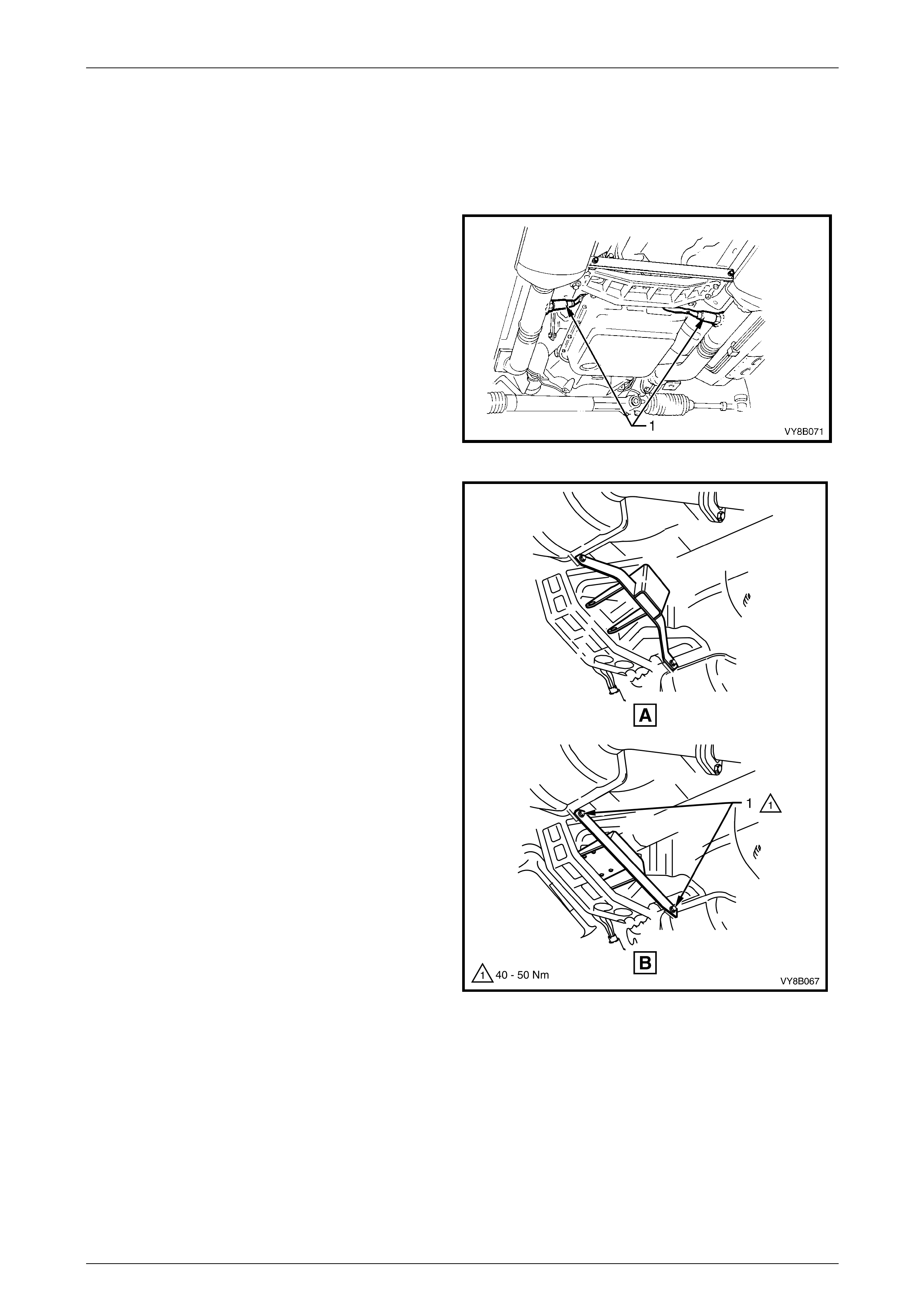
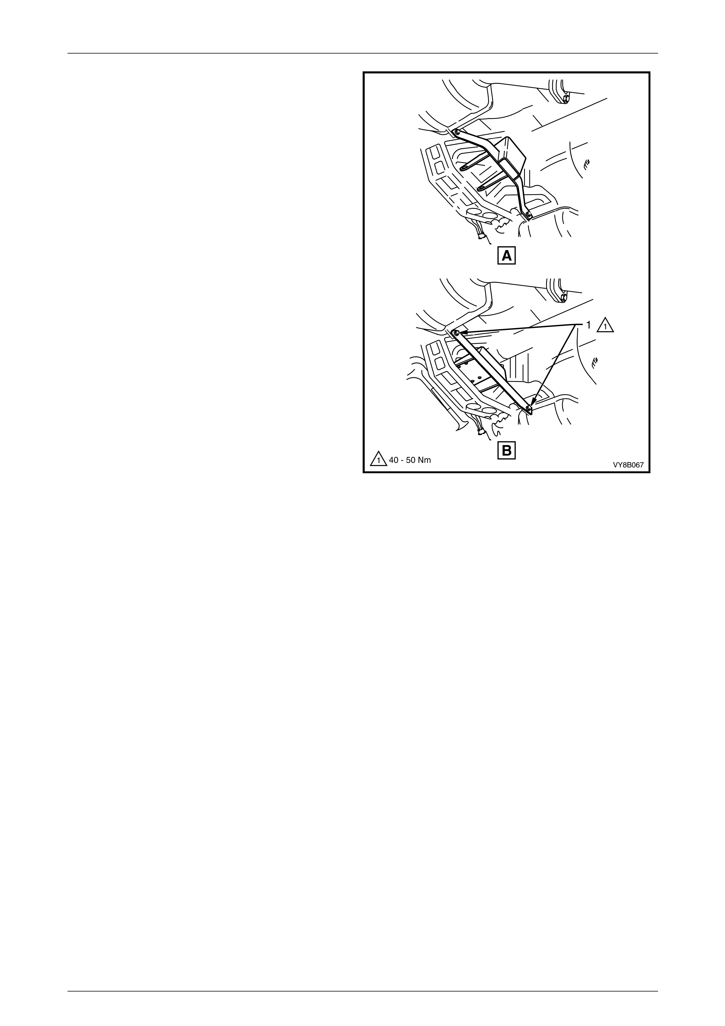
2 Remove the transmission to catalytic converter
support bracket bolts (1).
NOTE
For manual transmission vehicles, refer to View
A. For automatic transmission vehicles, refer to
View B.
Figure 8B – 25
Exhaust System Page 8B-18
Page 8B-18
3 Support the exhaust system and remove the
upper (1) and lower (2) fastening nuts from the
exhaust manifold to exhaust pipe flange studs on
both sides.
Figure 8B – 26
4 Remove the two support hanger retainer clips (1) and
the two support rubbers (2) from the tailpipe support
hangers.
Figure 8B – 27
5 Remove the support hanger retainer clip (1) and the
support rubber (2) from the upstream side of the rear
muffler assembly.
Figure 8B – 28
6 Support the exhaust system and disconnect the
intermediate muffler from the support hangers by
removing the retainer clips (1) and the support
rubbers (2).
7 Carefully lower and remove the exhaust assembly
from the vehicle, taking care not to damage the
exhaust gas oxygen sensors.
Figure 8B – 29
Exhaust System Page 8B-19
Page 8B-19
Reinstall
Installation of the full exhaust system is the reverse of the removal procedure, noting the following points:
1 Support the exhaust system at all times.
2 Clean threads of flange studs and fastening nuts with a suitable cleaning solvent.
3 Apply high temperature anti-seize compound to the manifold to front pipe flange studs and align the front pipe
flange over the studs.
4 Hand tighten the upper fastening nut (1) to the stud
on both sides.
5 Hand tighten the lower fastening nut (2) to the stud
on both sides.
6 Tighten the upper then lower fastening nuts so that
approximately equal amounts of thread are showing.
7 Tighten the upper then lower fastening nuts to the
specified torque.
Exhaust manifold to front
pipe flange stud attaching nut
torque specification..................................... 18 – 35 Nm
Figure 8B – 30
8 Ensure that the rear exhaust pipe slides unobstructed into the intermediate exhaust pipe slip joint, and that the
alignment key is positioned in the slip joint groove.
9 Evenly tighten the U-bolt clamp nuts to the specified torque:
U–bolt clamp assembly fastening
nut torque specification................................20 – 30 Nm
10 Ensure all support rubbers are under load
11 Ensure that correct body clearances are maintained throughout the full exhaust system, refer to
6 Exhaust System Clearances.
NOTE
If steps 10 or 11 are not achieved, refer to
3.7 Tightening Sequence in this Section.
12 Connect the wiring harness connectors for each of the two oxygen sensors.
Exhaust System Page 8B-20
Page 8B-20
3.4 Rear Exhaust Assembly
Remove
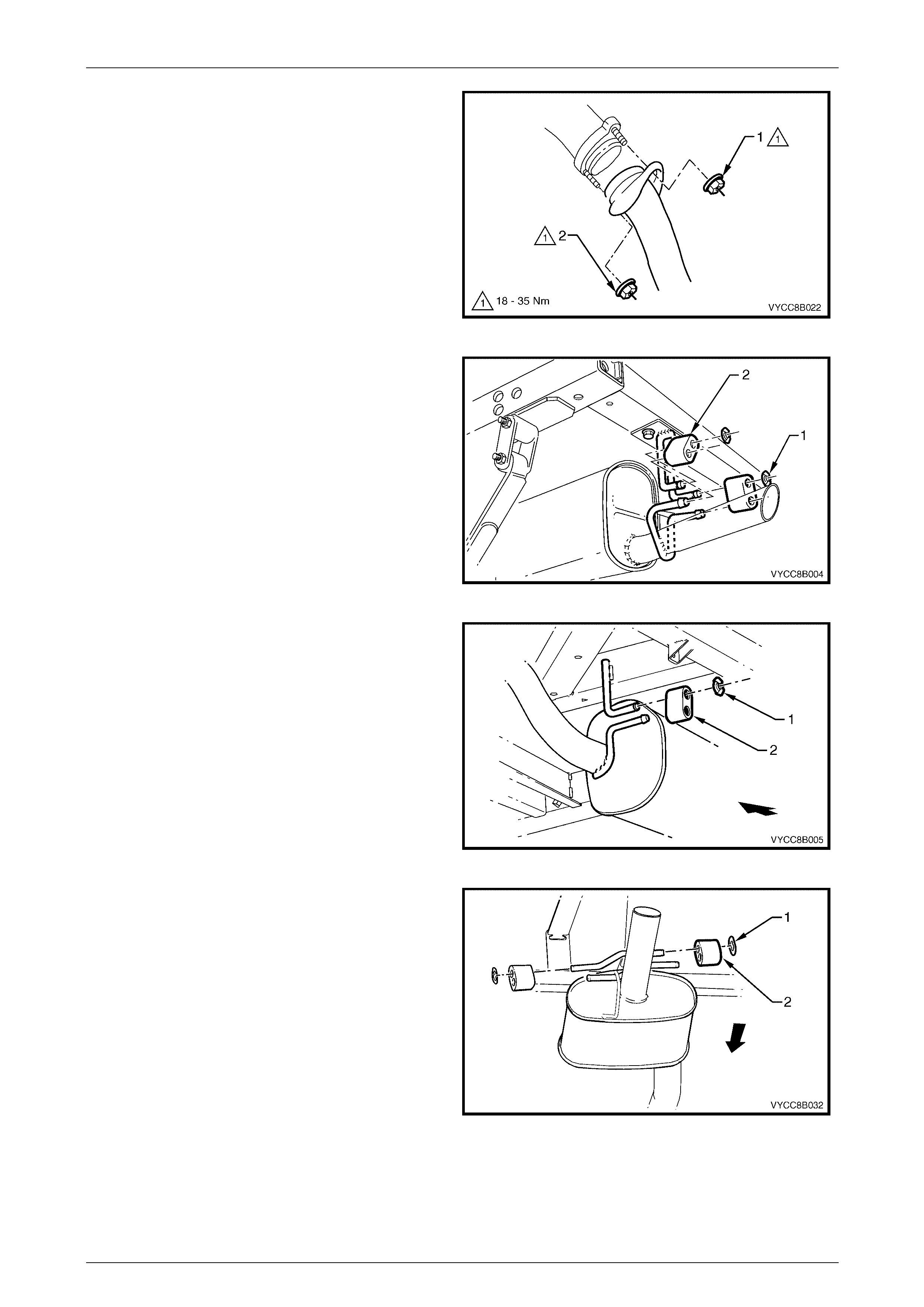
1 Remove the two support hanger retainer clips (1) and
the two support rubbers (2) from the support hangers.
Figure 8B – 31
2 Remove the two retaining nuts (1), the U-bolt (2) and
the clamp plate (3) from the intermediate to rear
exhaust pipe slip joint.
3 Carefully slide the rear exhaust pipe out of the
intermediate exhaust pipe end slip joint.
4 Remove the rear exhaust assembly.
Figure 8B – 32
Reinstall
Installation of the rear exhaust assembly is the reverse of the removal procedure, noting the following:
1 Ensure that the rear exhaust pipe slides unobstructed into the intermediate exhaust pipe slip joint, and that the
alignment key is positioned in the slip joint groove.
2 Evenly tighten the U-bolt clamp nuts to the specified torque:
U–bolt clamp assembly fastening
nut torque specification................................20 – 30 Nm
3 Ensure all support rubbers are under load.
4 Ensure that correct body clearances are maintained throughout the full exhaust system. Refer to
6 Exhaust System Clearances in this Section.
NOTE
If steps 3 or 4 are not achieved, refer to
3.7 Tightening Sequence in this Section.
5 Connect the wiring harness connectors for each of the two oxygen sensors.
Exhaust System Page 8B-21
Page 8B-21
3.5 Intermediate Exhaust Assembly
Remove
1 Remove the rear exhaust assembly. Refer to 3.4 Rear Exhaust Assembly in this Section.
The front exhaust assembly must be
supported during and after this procedure.
2 Support the intermediate and front exhaust
assemblies and remove the two bolts (1) from each of
the two flange joints.
3 Separate the intermediate exhaust assembly from the
front exhaust assembly and remove each flange
gasket (2) from between each of the flange joints.
Figure 8B – 33
4 Remove the pair of retainer clips (1) and support
rubbers (2) from the intermediate muffler support
hangers. Remove the intermediate exhaust
assembly.
Figure 8B – 34

Exhaust System Page 8B-22
Page 8B-22
Reinstall
Installation of the intermediate exhaust assembly is the reverse of the removal procedure, noting the following:
1 Support the exhaust system at all times.
2 Clean the threads of all flange bolts with a suitable cleaning solvent.
3 Check flange gaskets for serviceability and replace where necessary.
4 Tighten the front pipe to intermediate pipe flange fastening bolts to the specified torque.
Intermediate to front exhaust assembly
flange stepped fastening bolt
torque specification......................................40 – 50 Nm
5 Ensure all support rubbers are under load.
6 Ensure that correct body clearances are maintained throughout the full exhaust system. Refer to
6 Exhaust System Clearances in this Section.
NOTE
If steps 5 or 6 are not achieved, refer to
3.7 Tightening Sequence in this Section.
7 Connect the wiring harness connectors for each of the two oxygen sensors.
Exhaust System Page 8B-23
Page 8B-23
3.6 Front Exhaust Assemblies
Remove
1 Disconnect the wiring harness connector from the
relevant oxygen sensor (1).
Figure 8B – 35
2 Support the intermediate and front exhaust
assemblies and remove the two bolts (1) from each of
the two flange joints.
3 Separate the intermediate exhaust assembly from the
front exhaust assembly and remove each of the
flange gaskets (2) from between the flange joints.
Figure 8B – 36
4 Remove the upper (1) and lower (2) fastening nuts
from the exhaust manifold to exhaust pipe flange
studs on both sides.
Figure 8B – 37
Exhaust System Page 8B-24
Page 8B-24
5 Support the front exhaust assemblies and remove the
transmission to catalytic converter support bracket
bolts (1).
NOTE
For manual transmission vehicles, refer to view
A. For automatic transmission vehicles, refer to
view B.
6 Carefully lower and remove the front exhaust
assembly from the vehicle, taking care not to damage
the oxygen sensors in the process.
Figure 8B – 38
Exhaust System Page 8B-25
Page 8B-25
Reinstall
Installation of the front exhaust assembly is the reverse of the removal procedure, noting the following points:
1 Support the exhaust system at all times.
2 Clean threads of flange studs, nuts and bolts with a suitable cleaning solvent.
3 Check flange gaskets for damage and replace where necessary.
4 Apply a high temperature anti-seize compound to the manifold to front pipe flange studs and align the front pipe
flange over the studs.
5 Install the upper fastening nut (1) to the stud on both
sides.
6 Install the lower fastening nut (2) to the stud on both
sides.
7 Tighten the upper and lower fastening nuts so that
approximately equal amounts of thread are showing.
8 Tighten the fastening nuts to the specified torque.
Exhaust manifold to front
pipe flange stud attaching nut
torque specification..................................... 18 – 35 Nm
9 Tighten the front pipe to intermediate pipe flange
fastening bolts to the specified torque.
Intermediate to front exhaust assembly
flange stepped fastening bolt
torque specification..................................... 40 – 50 Nm
Figure 8B – 39
10 Tighten the transmission to catalytic converter mounting bracket bolts to the specified torque.
Transmission to catalytic converter
mounting bracket bolt
torque specification.......................................40 –50 Nm
11 Ensure all exhaust system support rubbers are under load.
12 Ensure that correct body clearances are maintained throughout the full exhaust system. Refer to
6 Exhaust System Clearances.
13 Connect the wiring harness connectors for each of the two oxygen sensors.
NOTE
If steps 11 or 12 are not achieved, refer to
3.7 Tightening Sequence in this Section.
Exhaust System Page 8B-26
Page 8B-26
3.7 Tightening Sequence
This procedure is only to be performed if the exhaust system positioning is not to specification.
Refer to Figure 8B – 41 for the following.
For all gasketed joints requiring adjustment,
check gasket for serviceability and replace
where necessary. Ensure that all fasteners
mentioned in steps 1 to 7 bellow, are loose
before conducting this procedure.
1 Tighten the front pipe to intermediate pipe flange fastening bolts (1) at the rear of the catalytic converters to the
specified torque.
Intermediate to front exhaust assembly
flange stepped fastening bolt
torque specification......................................40 – 50 Nm
2 Check that the rear exhaust pipe aligning key is seated within the intermediate exhaust pipe’s end slip joint groove.
Position the U-bolt clamp along the intermediate to rear slip joint and tighten the pair of fastening nuts (2) to the
specified torque.
U–bolt clamp assembly securing
nut torque specification................................20 – 30 Nm
3 Hand tighten the upper fastening nut (1) to the stud
on both sides.
4 Hand tighten the lower fastening nut (2) to the stud
on both sides.
5 Tighten the upper then lower fastening nuts (1 and 2)
on both sides so that approximately equal amounts of
thread are showing.
6 Tighten the upper then lower fastening nuts (1 and 2)
on both sides to the specified torque.
Exhaust manifold to front
pipe flange stud attaching nut
torque specification..................................... 18 – 35 Nm
Figure 8B – 40
7 Tighten the transmission to catalytic converter support bracket bolts (3) to the specified torque.
Transmission to catalytic converter
support bracket bolt
torque specification......................................40 – 50 Nm
8 Ensure that all five support rubbers (4 and 5) are under load. If this is not achieved, loosen the respective joints in
the reverse order to steps 1 to 7. Load the hangers and re-tighten in the sequence described, from steps
1 to 7.
Exhaust System Page 8B-27
Page 8B-27
NOTE
The exhaust system should be self-aligning and
not require further adjustment, provided step 8 is
achieved. To ensure that correct clearances are
maintained throughout the full exhaust system,
refer to 6 Exhaust System Clearances for the
correct values.
Figure 8B – 41
Exhaust System Page 8B-28
Page 8B-28
4 Service Operations – Tailpipe
Hanger Bracket
Should the tailpipe hanger bracket require replacement, the following procedure is recommended.
Remove
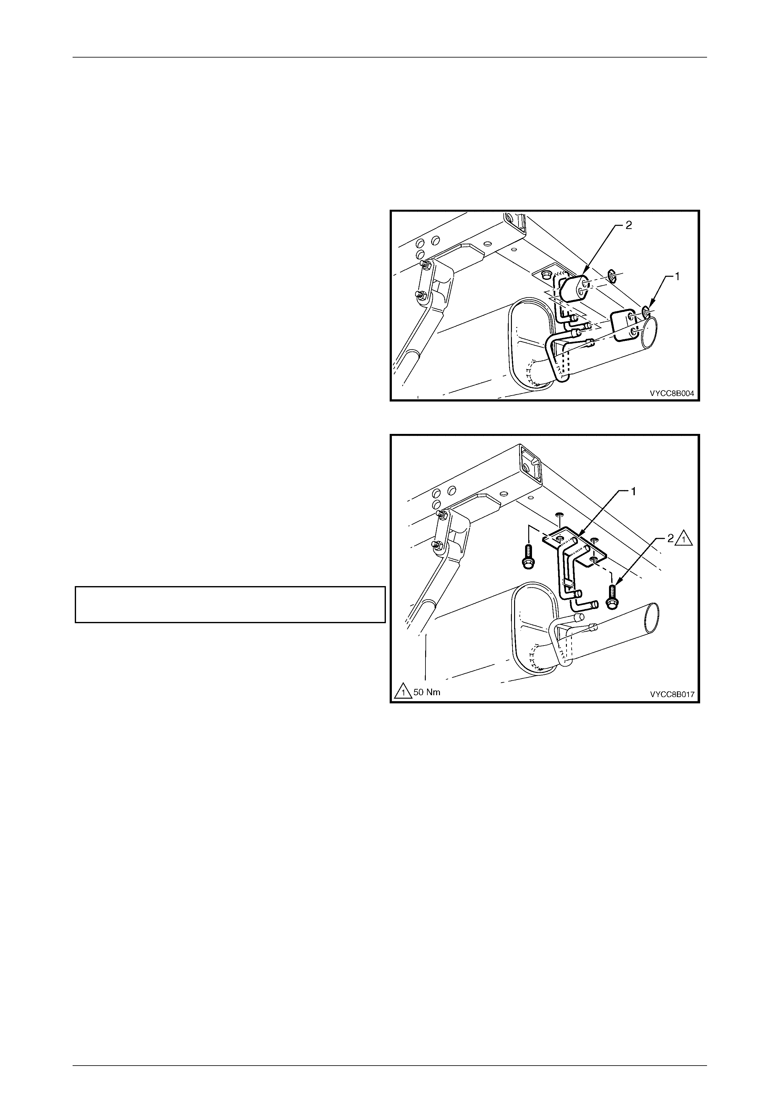
1 Support the exhaust system and remove the two
support hanger retainer clips (1) and the two support
rubbers (2) from the tailpipe support hangers.
Figure 8B – 42
2 Remove the two tailpipe hanger bracket fastening
bolts.
Reinstall
Installation of the tailpipe hanger bracket is the reverse of
the removal procedure, noting the following:
1 Tighten the tailpipe hanger bracket fastening bolts to
the correct torque specification.
Tailpipe hanger bracket to subframe
fastening bolt torque specification....................... 50 Nm
Figure 8B – 43

Exhaust System Page 8B-29
Page 8B-29
5 Service Operations – Exhaust
System Heat Shields
5.1 Service Notes
A formed metal heatshield is installed above the intermediate muffler and a pair of butyl reflective foil heat shields are
glued to the underbody above the front pipes.
To avoid the possibility of personal injury by
burns, allow the exhaust system to cool down
before attempting this operation and wear
heat resistant protective gloves when
handling heated butyl foil insulators.
Exhaust System Page 8B-30
Page 8B-30
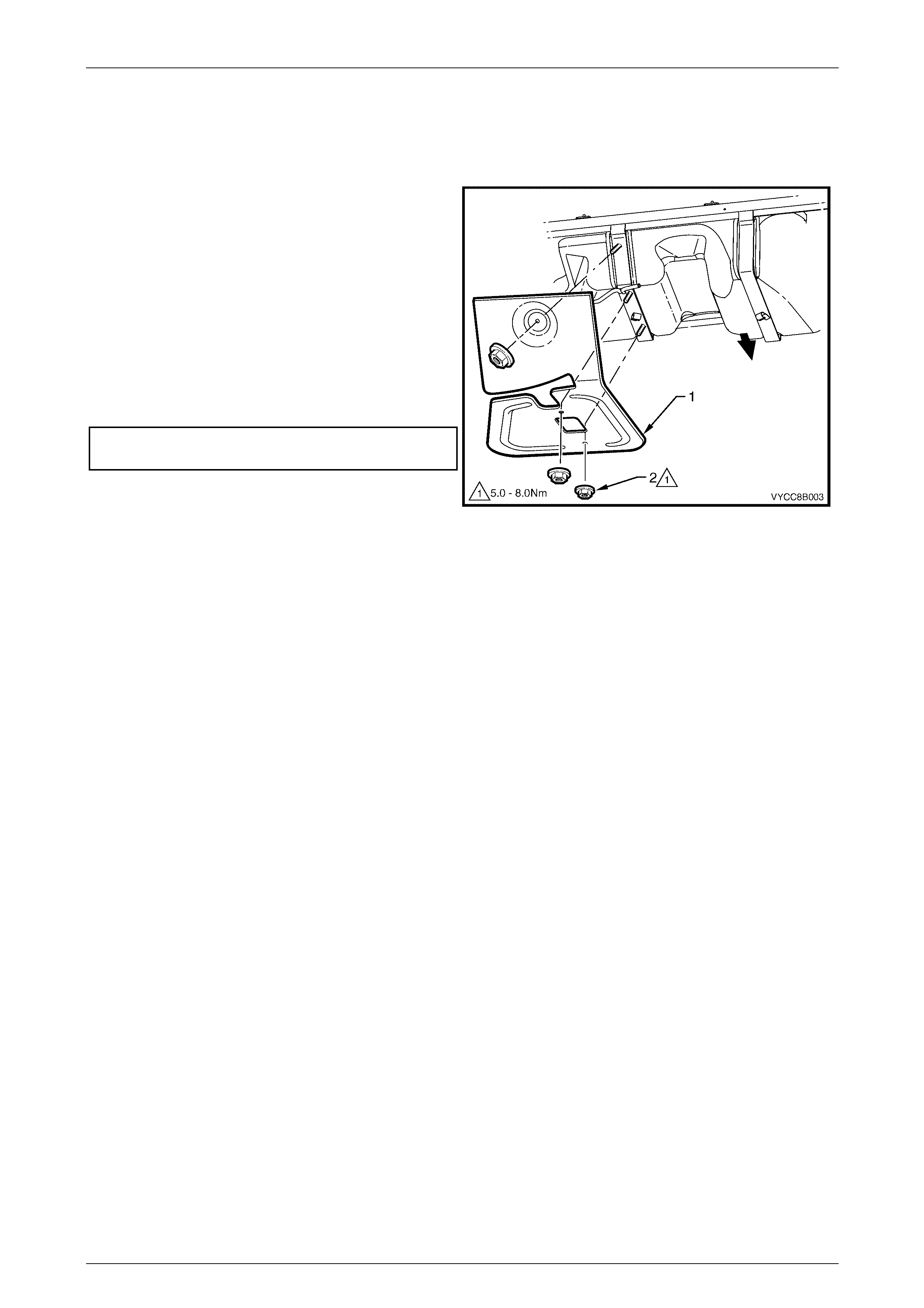
5.2 Heat Shield – Intermediate Muffler
Remove
1 Disconnect the brake line from the fuel tank strap
brake line clip and move brake line to one side.
2 Remove the stud fastening nuts (2) from each of the
body mounted studs (3) and remove the intermediate
muffler heat shield (1).
Reinstall
Installation of the intermediate heat shield is the reverse of
the removal procedure, noting the following:
1 Tighten the stud fastening nut to the correct torque
specification.
Intermediate muffler heat shield stud
fastening nut torque specification ............. 5.0 – 8.0 Nm
Figure 8B – 44
Exhaust System Page 8B-31
Page 8B-31
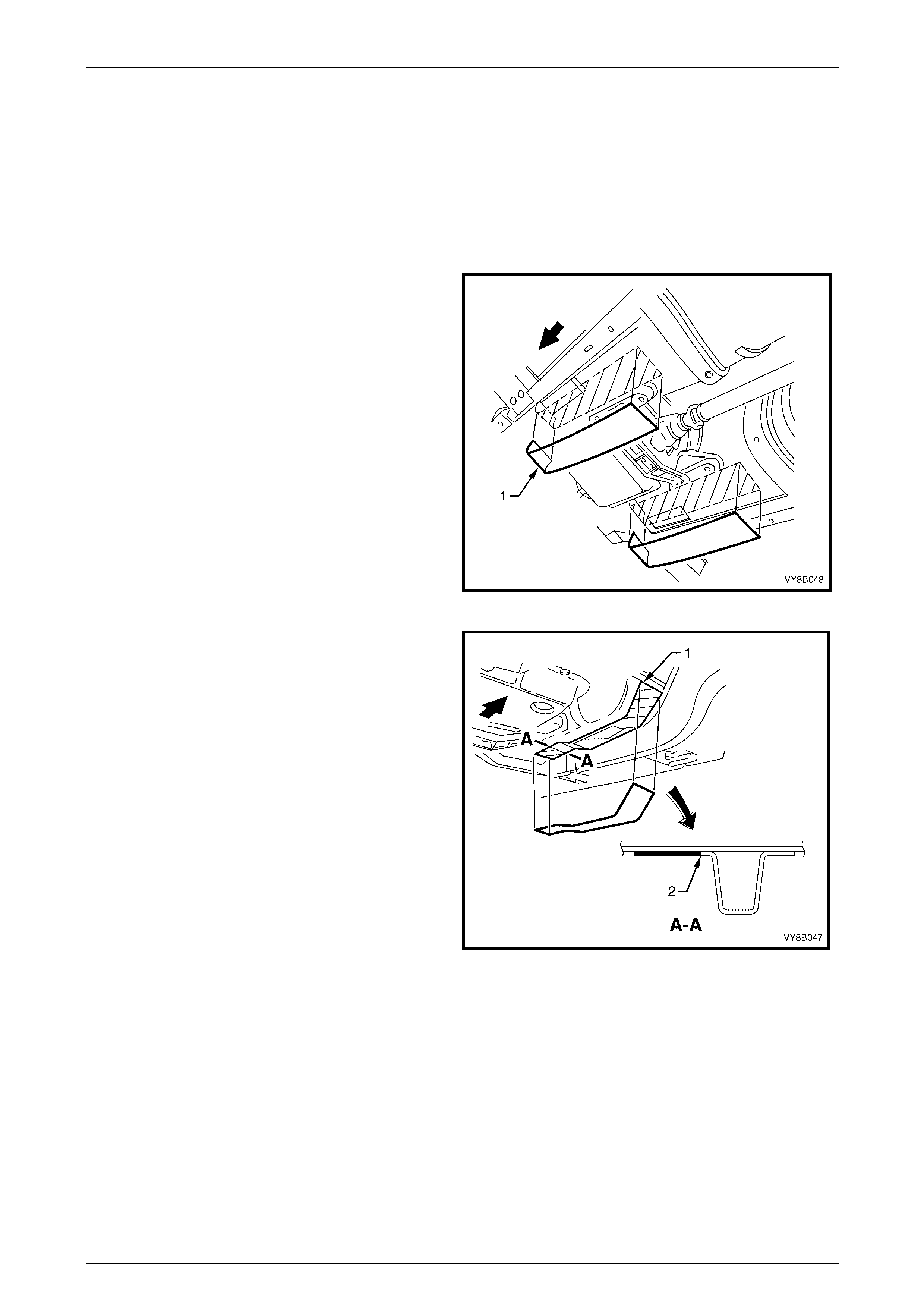
5.3 Butyl Reflective Foil Insulators
Remove
1 If required, remove the front exhaust assembly, refer to:
• 2.2 Exhaust System for V6
• 3.2 Exhaust System for GEN III V8
2 Peel the foil insulator/s (1) to be replaced from the
under floor and discard.
3 Use a solvent soaked rag to remove all traces of the
old insulator adhesive, sealer overspray or paint
overspray, should the vehicle have been repaired.
Reinstall
NOTE
Do not attempt to re-use a removed butyl
reflective foil insulator. Always use a new part.
1 Use a solvent soaked rag to remove all traces of the
old insulator adhesive, sealer overspray or paint
overspray, should the vehicle have been repaired.
2 Heat a new butyl reflective foil insulator to 40 ± 5° C.
Figure 8B – 45
3 Wearing heat resistant protective gloves, peel the
adhesive protective paper from the new butyl
reflective foil insulator and apply the insulator to the
cleaned under floor area in the same position as the
removed part. The front facing end of the foil should
start at the join in the floor (1) and align with the edge
of the longitudinal flange (2). Smooth out any air
bubbles in the process.
Figure 8B – 46
Exhaust System Page 8B-32
Page 8B-32
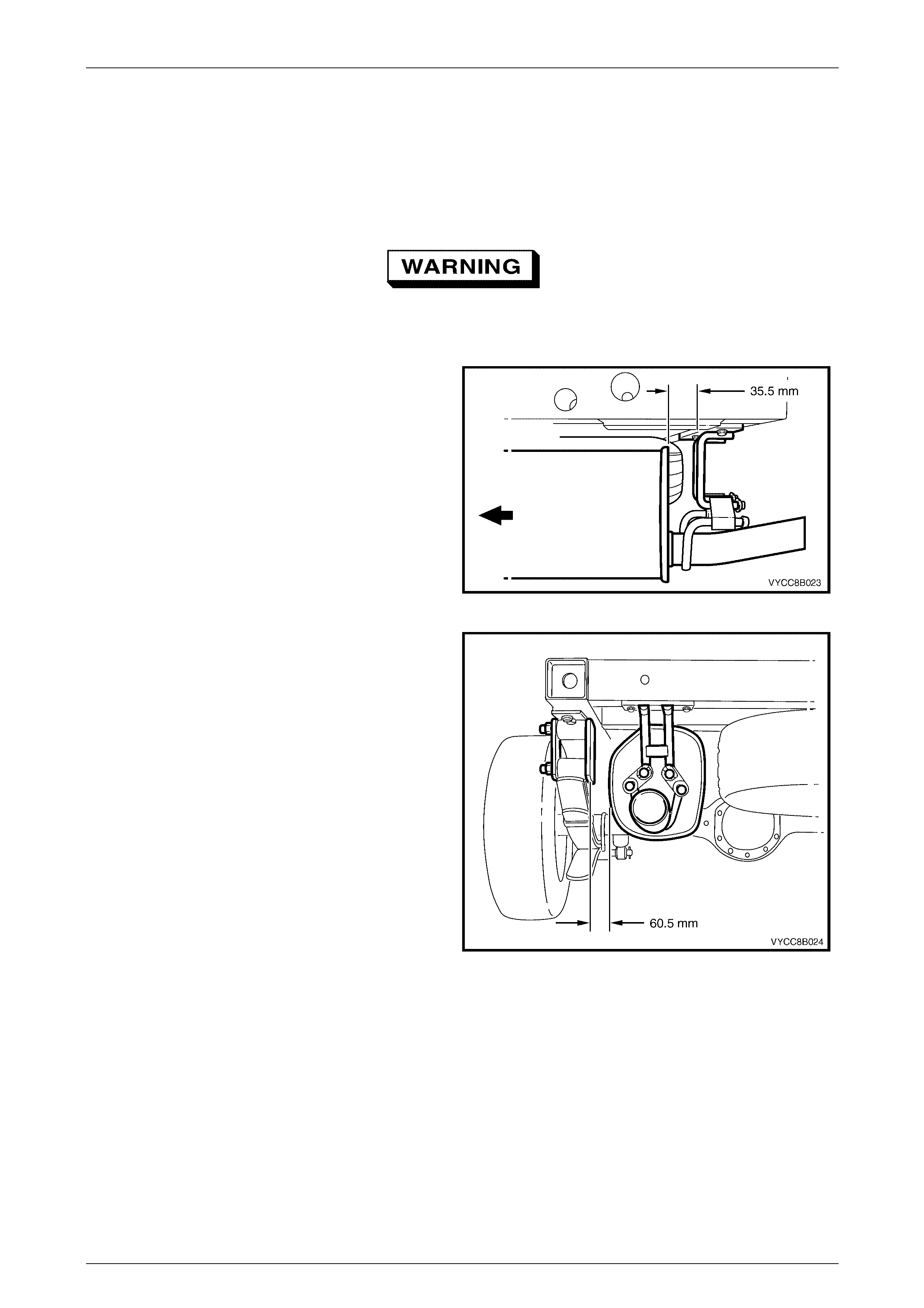
6 Exhaust System Clearances
The following diagrams indicate the exhaust system clearances specified for cab chassis utility vehicles fitted with either
the V6 or GENIII V8 engine. Clearances should be checked upon installation of exhaust components to prevent parts
interference and ensure correct alignment. Refer to Figure 8B – 4 and Figure 8B – 23 for the location of V6 and
GEN III V8 exhaust system parts respectively.
To avoid the possibility of personal injury,
allow the exhaust system to cool dow n before
attempting this operation.
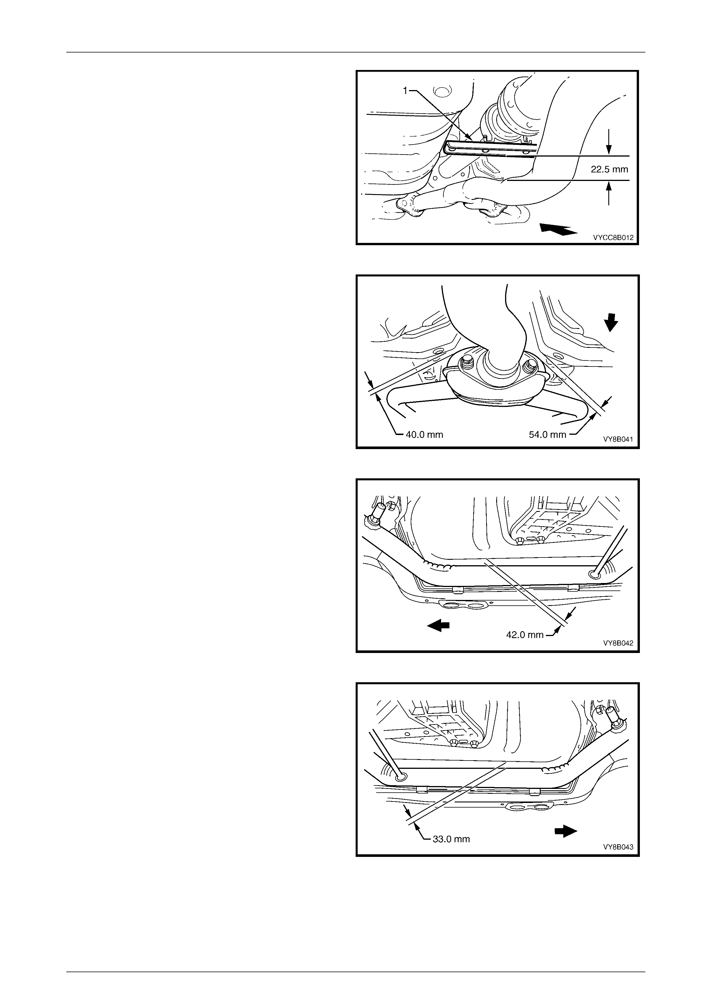
1 Check the rear muffler to hanger bracket clearances.
Figure 8B – 47
2 Check the rear muffler to rear leaf spring assembly
clearances.
Figure 8B – 48
Exhaust System Page 8B-33
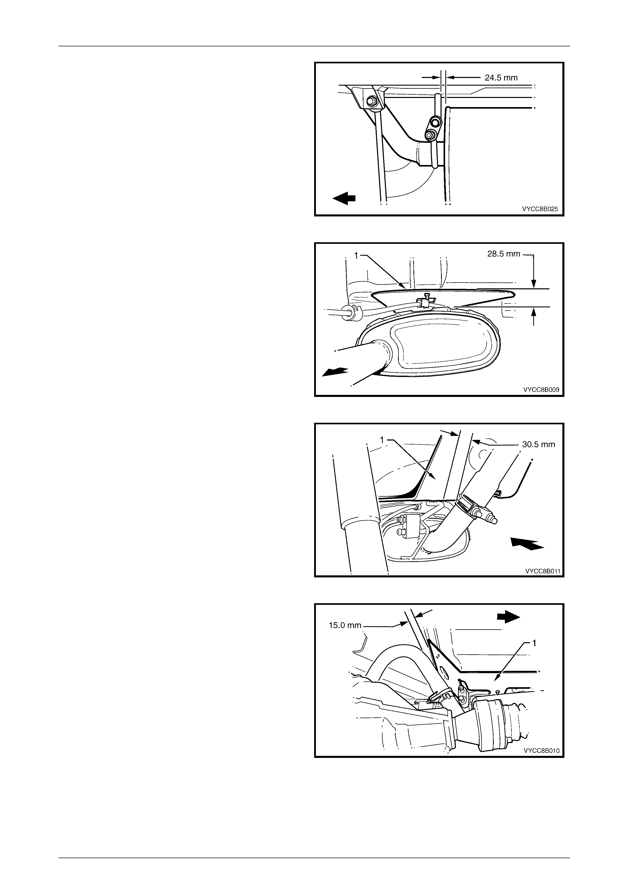
Page 8B-33
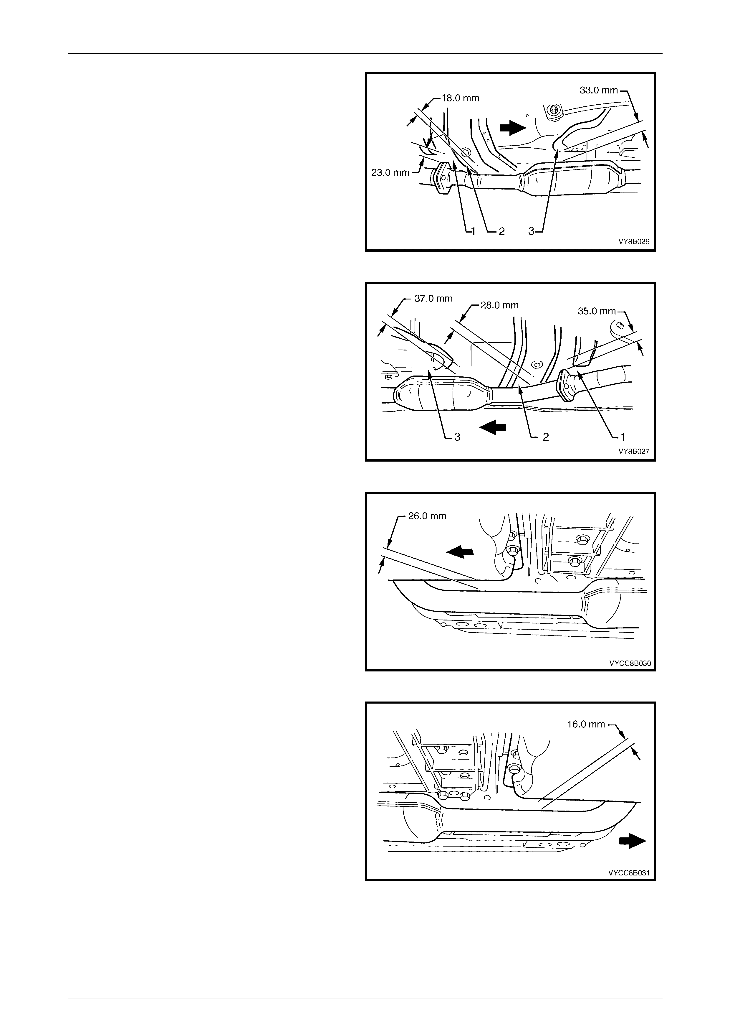
3 Check the clearance between the upstream face of
the rear muffler and the hanger peg.
Figure 8B – 49
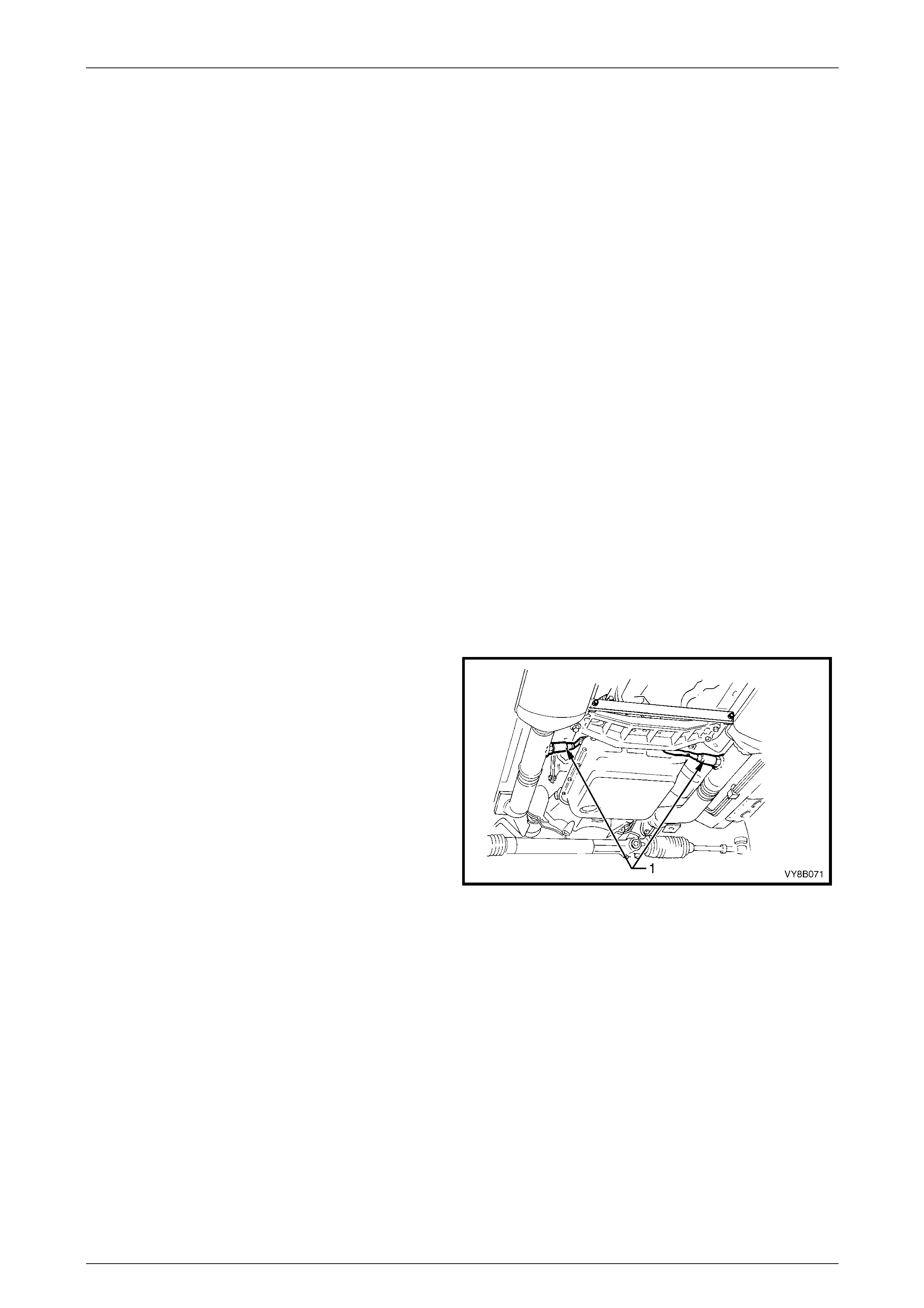
4 Check the intermediate muffler to underbody
heatshield (1) clearance.
Figure 8B – 50
5 Check the U-clamp to underbody heatshield (1)
clearance.
Figure 8B – 51
6 Check the intermediate pipe to underbody
heatshield (1) clearance.
Figure 8B – 52
Exhaust System Page 8B-34
Page 8B-34
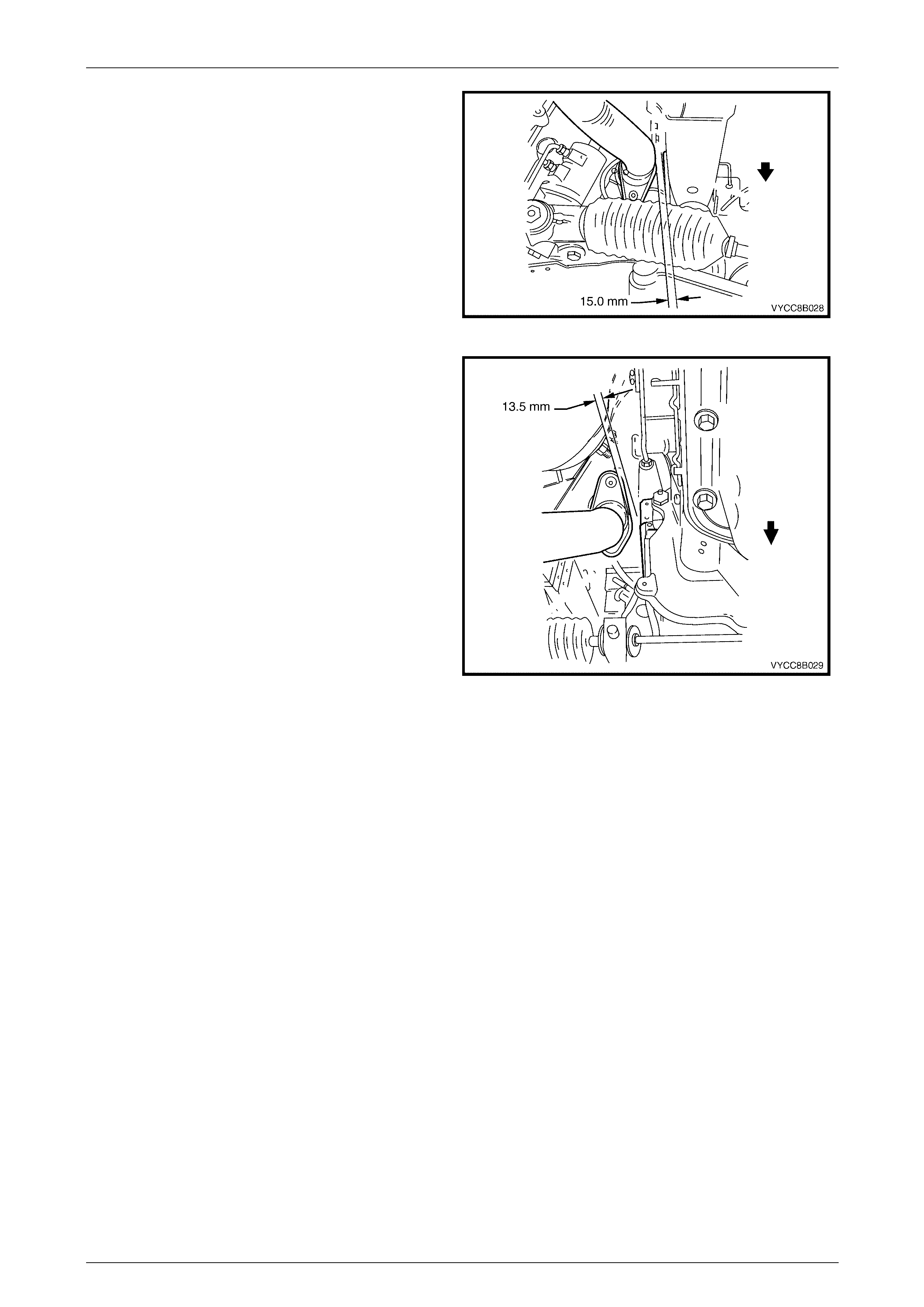
7 For GEN III V8 vehicles, check the intermediate
exhaust pipe to centre bearing carrier clearance.
Figure 8B – 53
8 For V6 vehicles:
a Check the catalytic converter to transmission
tunnel roof support clearances.
Figure 8B – 54
b Check the right-hand side front exhaust pipe to
underbody foot well clearances.
Figure 8B – 55
c Check the left-hand side front exhaust pipe to
underbody foot well clearances.
Figure 8B – 56
Exhaust System Page 8B-35
Page 8B-35
9 For GEN III V8 vehicles:
a Check the left-hand side intermediate exhaust
pipe flange to underbody panel (1) clearances.
b Check the left-hand side front exhaust pipe to
transmission tunnel roof support (2) clearance.
c Check the left-hand side catalytic converter to
transmission crossmember support bracket (3)
clearance.
Figure 8B – 57
d Check the right-hand side intermediate exhaust
pipe flange to underbody panel (1) clearances.
e Check the right-hand side front exhaust pipe to
transmission tunnel roof support clearance.
f Check the right-hand side catalytic converter to
transmission crossmember support bracket (3)
clearance.
Figure 8B – 58
g Check the right-hand side front exhaust pipe to
automatic transmission oil pan clearances.
Figure 8B – 59
h Check the left-hand side front exhaust pipe to
automatic transmission oil pan clearances.
Figure 8B – 60
Exhaust System Page 8B-36
Page 8B-36
10 Check the front exhaust pipe to the right-hand side
front longitudinal assembly clearances.
Figure 8B – 61
11 Check the front left-hand side exhaust pipe to engine
block clearances.
Figure 8B – 62

Exhaust System Page 8B-37
Page 8B-37
7 Exhaust System Diagnosis
CONDITION PROBABLE CAUSE CORRECTION
Leaks at pipe joints. Tighten U-bolt nuts and joint
bolts to the specified torques.
Damaged or improperly installed
converter sealing ring/gaskets. Replace sealing ring/gasket as
necessary.
Leaking exhaust gases
Burned or rusted out exhaust pipe or
muffler/s. Replace component as
necessary.
Leaks at manifold or pipe
connections.
Tighten clamps at leaking
connections to specified torques.
Replace gasket as required.
Burned or blown out pipe or muffler/s. Replace pipe/muffler assembly
as necessary.
Exhaust manifold/s cracked or
broken. Replace manifold.
Exhaust noises
Leak between manifold/s and cylinder
head/s. Tighten manifold to cylinder
head studs to specified torque.
Clogged catalytic converter (may
result from serious engine
malfunction). Replace catalytic converter.
Loss of engine power, hesitation,
surging, poor fuel economy,
stalling or hard starting Crushed pipe work. Replace pipe work.
Dislodged tubes and/or baffles in
muffler. Replace muffler.
Internal rattling in muffler Catalytic converter monolith has
crumbled and pieces blown into
muffler.
Replace catalytic converter
assembly and affected muffler.
Damaged, worn, missing or
improperly installed support rubbers. Check and replace as
necessary.
Damaged mounting hangers or pegs. Service / replace hangers or
pegs as necessary.
Check clearances and adjust
joint alignment as necessary.
Improper alignment. Tighten all fasteners according
to tightening sequence and the
specified torques.
Rattling or knocking exhaust
system
Damaged or incorrect exhaust system
components. Replace damaged or incorrect
components as necessary.

Exhaust System Page 8B-38
Page 8B-38
8 Specifications
Exhaust System Type:
V6 ......................................................................................................................Single system
GEN III V8.................................................. Dual system to rear of twin intermediate mufflers,
..........................................................................single pipe rear muffler/tailpipe arrangement.
Material:
Engine Pipes...............................................................................................409 stainless steel
Intermediate Muffler....................................................................................409 stainless steel
Rear Muffler................................................................................................409 stainless steel
Catalytic Converter:
Make.................................................................................................................... AC Australia
Type..........................................................................................................Three way monolith
Outer Steel Shell Material...........................................................................409 stainless steel
Inlet Diameter
V6 ....................................................................................................................50.8 mm x 2
GEN III V8 A/T...................................................................................................... 50.8 mm
GEN III V8 M/T...................................................................................................... 60.5 mm
Outlet Diameter
V6 ......................................................................................................................... 60.5 mm
GEN III V8 A/T...................................................................................................... 50.8 mm
GEN III V8 M/T...................................................................................................... 60.5 mm
Monolith
Material.................................................................................................Extruded Cordierite
Volume
V6 Engine ..............................................................................................................1.8 litres
GEN III V8 A/T..............................................................................................1.4 litres each
GEN III V8 M/T..............................................................................................1.8 litres each
Cells/cm.sq.......................................................................................................................... 62

Exhaust System Page 8B-39
Page 8B-39
9 Torque Wrench Specifications
Intermediate to front exhaust assembly flange
fastening bolt...................................................................................40 – 50 Nm
Intermediate to front exhaust assembly flange
stepped fastening bolt .....................................................................40 – 50 Nm
U-bolt clamp assembly securing nuts..............................................20 – 30 Nm
Front pipe to exhaust manifold stud flange fastening nut................18 – 35 Nm
Transmission to catalytic converter support bracket
fastening bolts .................................................................................40 – 50 Nm
Intermediate muffler heat shield stud fastening nut.......................5.0 – 8.0 Nm
Tailpipe support hanger bracket to subframe
fastening bolt torque specification...........................................................50 Nm