
SECTION 12D - AUDIO SYSTEMS
IMPORTANT
Before performing any Service Operation or other procedure described in this Section, refer to
Section 00 CAUTIONS AND NOTES for correct workshop practices with regard to safety and/or
property damage.
1. GENERAL I NFORMATI ON
All WH models are fitted with a high performance double DIN size AM/FM stereo radio/cassette player combination.
The audio systems fitted to both the WH Statesman and the WH Caprice comprise a radio/cassette player with a 6
disc CD player/changer installed in the rear compartment of the vehicle (refer to 2.12 COMPACT DISC PLAYER/
CHANGER INSTALLATION in this Section).
All radio/cassette player assemblies incorporate Personal Identification Number (PIN) security code theft deterrent
and flashing LED features.
WH vehicles have speakers mounted in each upper corner of the instrument dash panel, and are also equipped
with unique 150 mm diameter twin cone speakers mounted in the front door trim side pockets and 150 mm co-axial
speakers mounted in the rear door trim side pockets.
The audio system fitted to WH vehicles features personal identity memories which individually memorises the
following settings for different ignition keys:
Last used volume level
Last used mode
FM1- radio memory presets
FM2- radio memory presets
AM- radio memory presets
Bass control settings
Treble control settings
Speaker balance setting
Speaker fader setting
Time/Frequency priority settings
Local On/Off setting
Telephone volume
Caprice only:
Digital Signal Processor (DSP) effects
Pre-program Equaliser (EQ) setting
Listening Position (POS) selected
The audio system fitted to the WH vehicles also features a pair of subwoofer speaker and bracket assemblies,
mounted on top of the rear parcel shelf. These speakers are powered by an additional amplifier located in the left-
hand side of the rear compartment, refer to 2.13 SUBWOOFER AMPLIFIER in this Section.
A connector for cellular telephone installation on WH vehicles is located under the centre console to the left of the
transmission gear shift lever. Wiring from this connector is connected into the back of the audio system to enable
audio system muting when the telephone is in use. The WH Statesman and the WH Caprice are provided with a
six-pin connector, which enables a telephone with a hands-free kit to use the vehicle’s speakers and the radio
volume control for the telephone audio.
A mobile phone antenna and cable is fitted to all WH vehicles to simplify the installation of a GSM (digital) mobile
phone hands-free kit. The exterior portion of the glass mounted antenna is not fitted to the vehicle, but is supplied
with the vehicle for fitting if required. However, the interior portion of the antenna is fitted to the rear screen and is
connected to the phone antenna cable which runs to the left-hand kick panel area, where it is coiled and clipped to
the left-hand end of the glove compartment lower rail.
A feature of the radio fitted to WH vehicles is the smart switch. The radio can be switched on without the need for
the ignition switch to be turned to ACC position. After an hour, circuits within the radio sense the ignition has not
been switched on and will switch the radio off. However, the radio can be switched ON again and the process will
repeat.
Techline
Techline
Techline
Techline

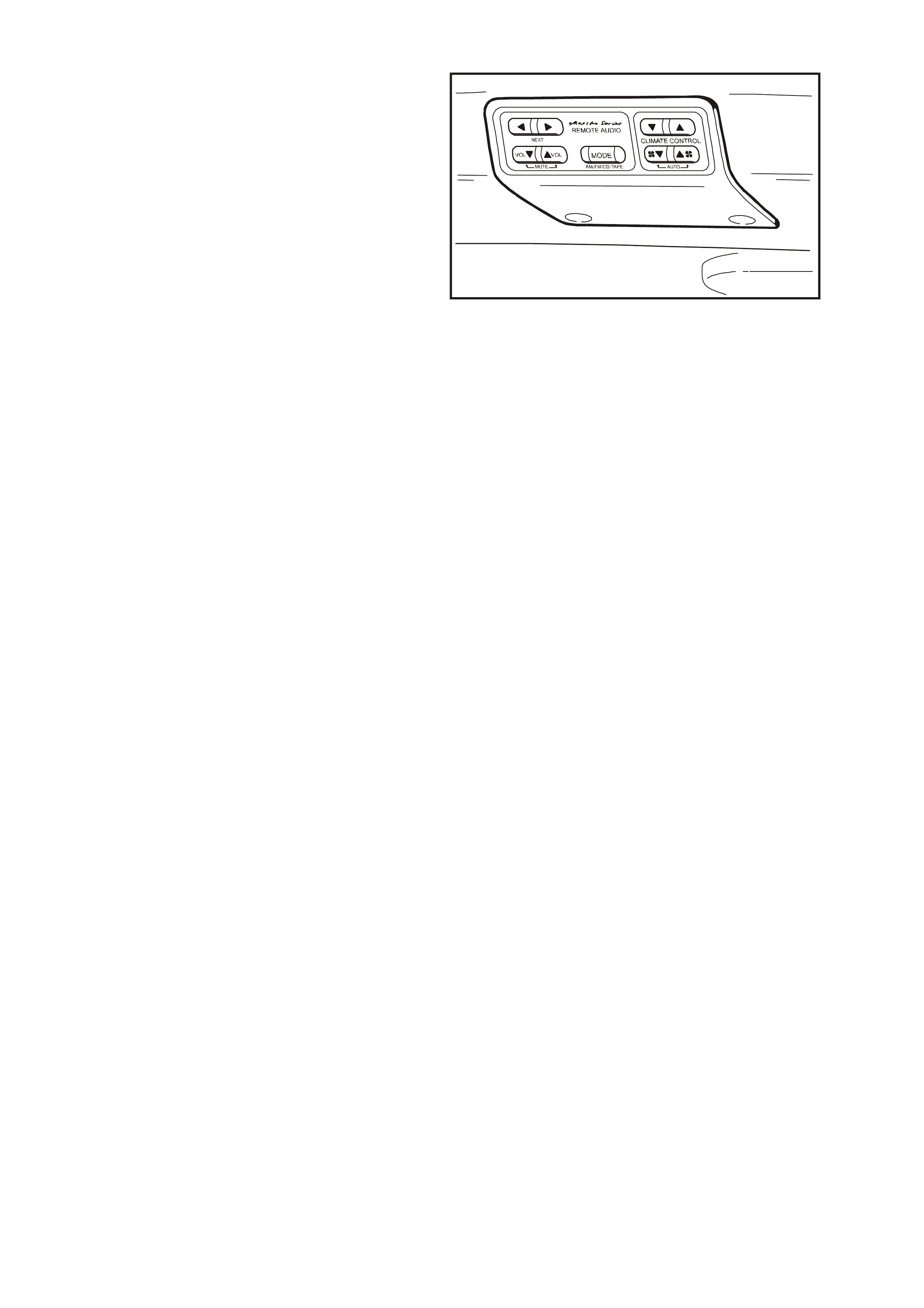
Additional features fitted to the WH Caprice audio system are rear seat headphone jacks, rear roof-mounted
speakers and a roof mounted rear remote control unit, which enables independent audio control for the rear
passengers when using the headphones. The rear remote control unit also provides controls for the climate control
air conditioning.
The audio output jacks for the headphones are located beneath the flap on the rear parcel shelf, and positioned on
either side of the child restraint anchor point. Insertion of one or both headphones into the audio output jacks mutes
the audio output from the vehicle’s rear speakers and switches the audio signal to the headphones.
When the headphones are plugged in, multi-moding of the audio sy stem is possible via the roof-mounted rear
remote controls. That is, whichever function is not being used by the occupants of the front seats can be used by
the occupants of rear seat and vice-versa. This can only be achieved while the headphones are plugged in.
If the headphones have been inadvertently left plugged in, audio from the rear speakers can be regained without the
need for the driver to stop the vehicle and physically remove the headphones from the jacks. Toggling the switch
(marked with the image of the headphones) on the radio facia enables the driver or front seat passenger to obtain
audio output from the rear speakers while the headphones remain plugged in.
The audio system for WH vehicles also includes steering wheel mounted audio system control buttons. Control of
the radio, tape and CD player functions can be accomplished without the need for the driver’s hands to be removed
from the steering wheel.
The radio reads the switch resistance from the steering wheel stereo controls via the clock spring coil harness.
WH vehicles are fitted with a power antenna, which is controlled by the Body Control Module (BCM) and the radio.
Refer to 2.8 POWER ANTENNA in this Section.
All WH vehicles have a height adjustable power antenna fitted as standard equipment. The power antenna
operation on these models is controlled via a switch located on the radio facia and in conjunction with the body
control module (BCM), refer to Section 12J-2 HIGH SERIES BODY CONTROL MODULE in of this Supplement.
To aid in the reception of FM radio signals a diversity antenna system is fitted to all WH vehicles.
The diversity antenna system consists of a diversity antenna, which is an integral part of the rear window glass, and
a diversity antenna module. The diversity antenna module is located under the rear parcel shelf trim on the
passenger side and amplifies the signal received by the diversity antenna. The amplified signal is sent to the radio
via a coaxial cable.
The radio receives signals from both the diversity and the fender mounted mast antenna and uses the stronger
signal for radio reception. This use of two antennae located in different positions on the vehicle makes the radio
reception less likely to be affected by signal nulls (multipathing) experienced in moving vehicles.
Operating instructions for the audio system accompany the WH Statesman & Caprice Owner’s Handbook in the
vehicle’s glove compartment.
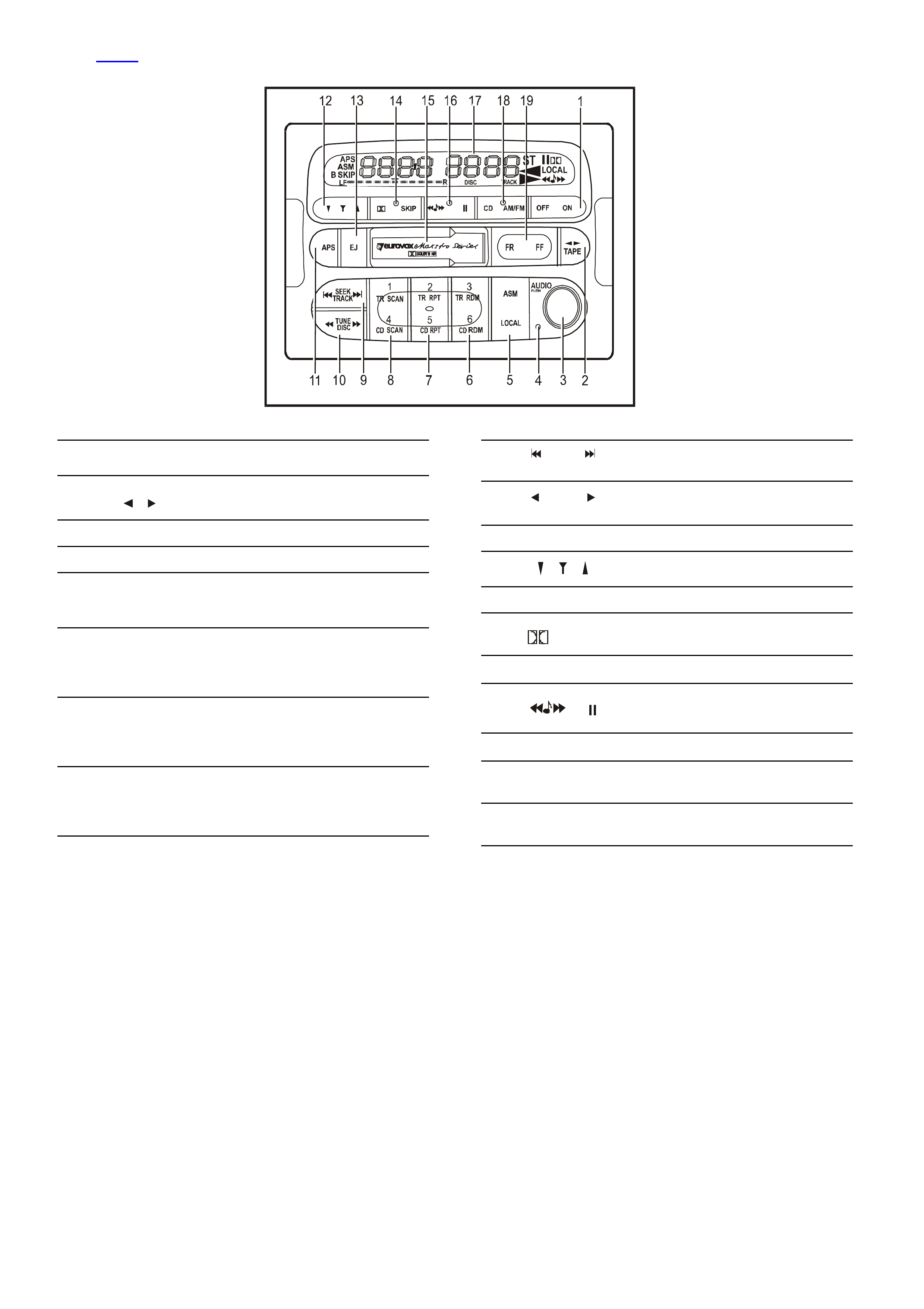
Fig. 12D-3 shows the radio/cassette/CD changer fitted to WH Statesman models with CD changer and power
antenna.
WH12D001
Figure 12D-1
1 OFF ON Power ON/OFF Switch
2TAPE
TAPE On
TAPE Program Selector
3AUDIO Pus h Audio Selector/Adj uster
4Security Indicat or Li ght
5ASM
LOCAL
RADIO Automatic Station Memory
RADIO Local /Distant Selector
6
3
TR RDM
6
CD RDM
RADIO Preset Memory 3
CD Track Random Play
RADIO Preset Memory 6
CD Disc Random Pl ay
7
2
TR RPT
5
CD RPT
RADIO Preset Memory 2
CD Track Repeat
RADIO Preset Memory 5
CD Disc Repeat
8
1
TR SCAN
4
CD SCAN
RADIO Preset Memory 1
CD Track Scan
RADIO Preset Memory 4
CD Disc Scan
9 SEEK
TRACK RADIO Seek Tuning
CD Track Selector
10 TUNE
DISC RADIO Manual Tuning
CD Disc Selector
11 APS TAPE Automatic Program Search
12 Elect ri c Antenna Height Adjust ment
13 EJ TAPE Eject
14 SKIP TAPE Blank Skip
TAPE Dolby B NR Selector
15 Casset te Door
16 TAPE Radio Monit or
CD Pause
17 Liquid Cryst a l Di splay
18 CD AM/FM RADI O Waveband Selec t or
CD On
19 FR FF TAPE Fast Rewind/Fast Forward
CD Track Cue/Track Review
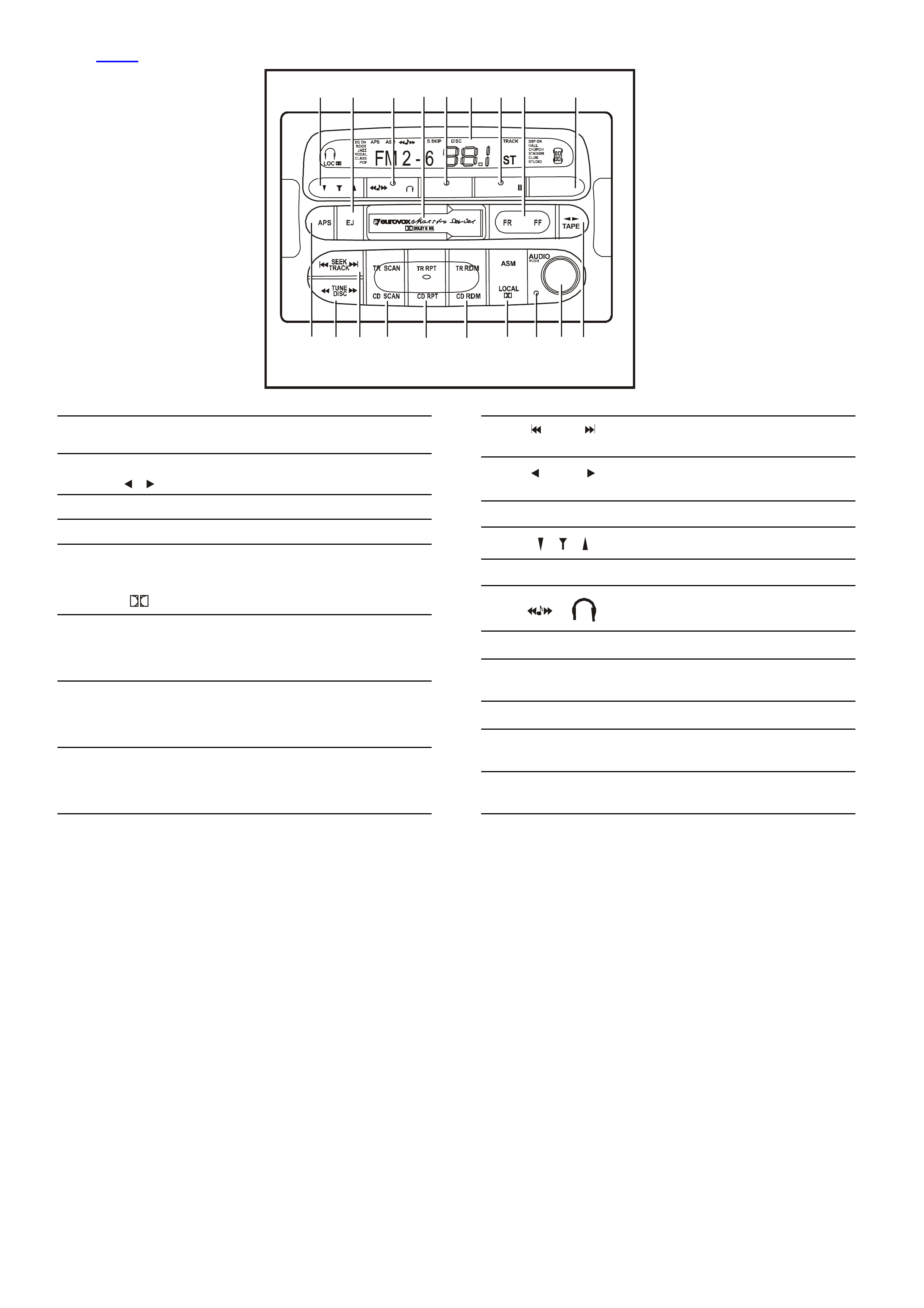
Fig. 12D-4 shows the radio/cassette/CD changer fitted to WH Caprice models with CD changer and power antenna.
AM/FM
CD
SKIP
DSPEQ POS ON
123
6
5
4
1
2
3
4
56
7
981011
12 13 14 15 16
17 18 19
WH12D002
Figure 12D-2
1 AM/FM ON RADIO Waveband S el ector
Power ON/OFF Switch
2TAPE
TAPE On
TAPE Program Selec t or
3 AUDIO Push Audio Selector/ Adjuster
4 Security Indicator Light
5
ASM
SKIP
LOCAL
RADIO Automatic Station Memory
TAPE Blank Skip
RADIO Local /Distant Selector
TAPE Dolby B NR Selector
6
3
TR RDM
6
CD RDM
RADIO Preset Memory 3
CD Track Random Play
RADIO Preset Memory 6
CD Disc Random Pl ay
7
2
TR RPT
5
CD RPT
RADIO Preset Memory 2
CD Track Repeat
RADIO Preset Memory 5
CD Disc Repeat
8
1
TR SCAN
4
CD SCAN
RADIO Preset Memory 1
CD Track Scan
RADIO Preset Memory 4
CD Disc Scan
9 SEEK
TRACK RADIO Seek Tuning
CD Track Selector
10 TUNE
DISC RADIO Manual Tuning
CD Disc Selector
11 AP S TAPE A ut omatic Program Search
12 Elect ri c Antenna Height Adjust ment
13 EJ TAPE Eject
14 TAPE Radio Monit or
Headphone Select or
15 Casset te Door
16 EQ DSP Preset Equaliser S el ector
Digital Signal Proc essor Selector
17 Liquid Cryst a l Di splay
18 POS CD Listeni ng Positi on S el ector
CD On/Pause Selector
19 FR FF TAPE Fast Rewind/Fast Forward
CD Track Cue/Track Review
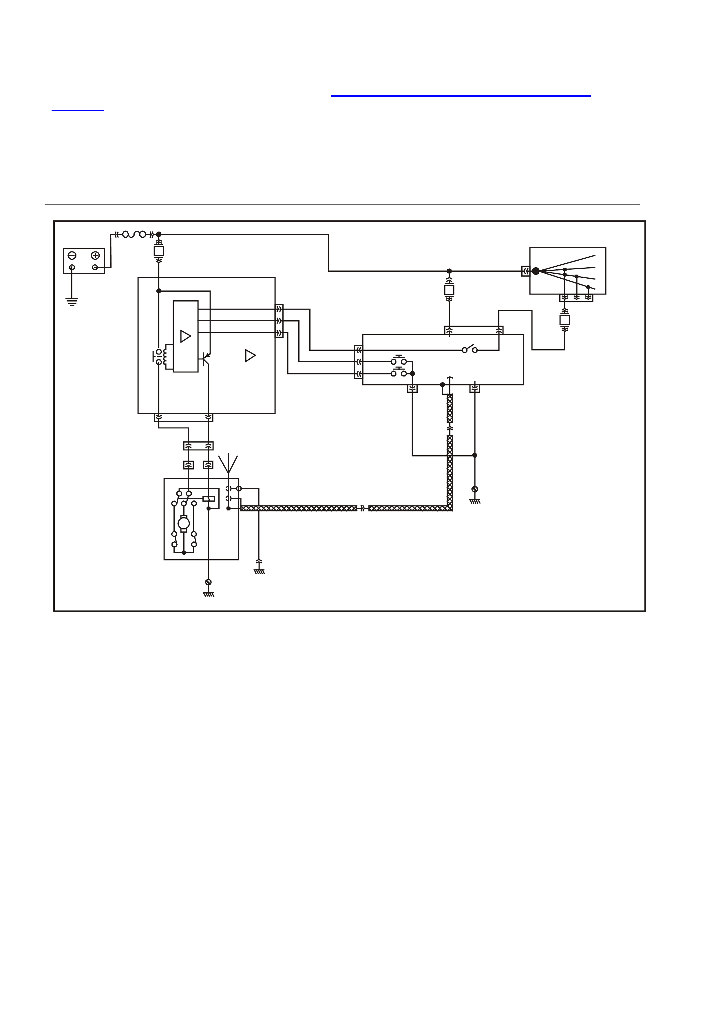
1.1 POWER ANTENNA OPERATION
For WH Series vehicles, the operation of the power antenna is controlled by the body control module and a
height adjustment switch located on the radio/cassette/CD player control panel below and to the left of the
liquid crystal display. For service information refer to Section 12J-2 HIGH SERIES BODY CONTROL
MODULE of this Supplement.
For all vehicles, when the radio is turned ON, control circuitry within the radio supplies voltage to the Body
Control Module (BCM) for as long as the radio is on. The BCM then determines what voltage and for how
long it is supplied to the antenna motor. The motor raises the antenna mast to full height for optimum radio
reception. The height of the antenna can be adjusted via the control on the radio facia.
Approximately 15 seconds after switching the ignition and/or radio OFF, the BCM switches voltage to the
opposite side of the antenna motor, reversing the operation of the motor to retract the antenna mast fully.
30
IGNITION
SWITCH OFF/ON
LOCK
ACC
IGN
START
RADIO ON
ANT DOWN
ANT UP
DOWN
UP
BODY
CONTROL
MODULE
RADIO ACC
GND
BATT
POWER
ANTENNA
MOTOR
ANT
DIRECTION
FJ F20
F23
F16
WH12D003
BATTERY
COAXIAL CABLE
Figure 12D-3
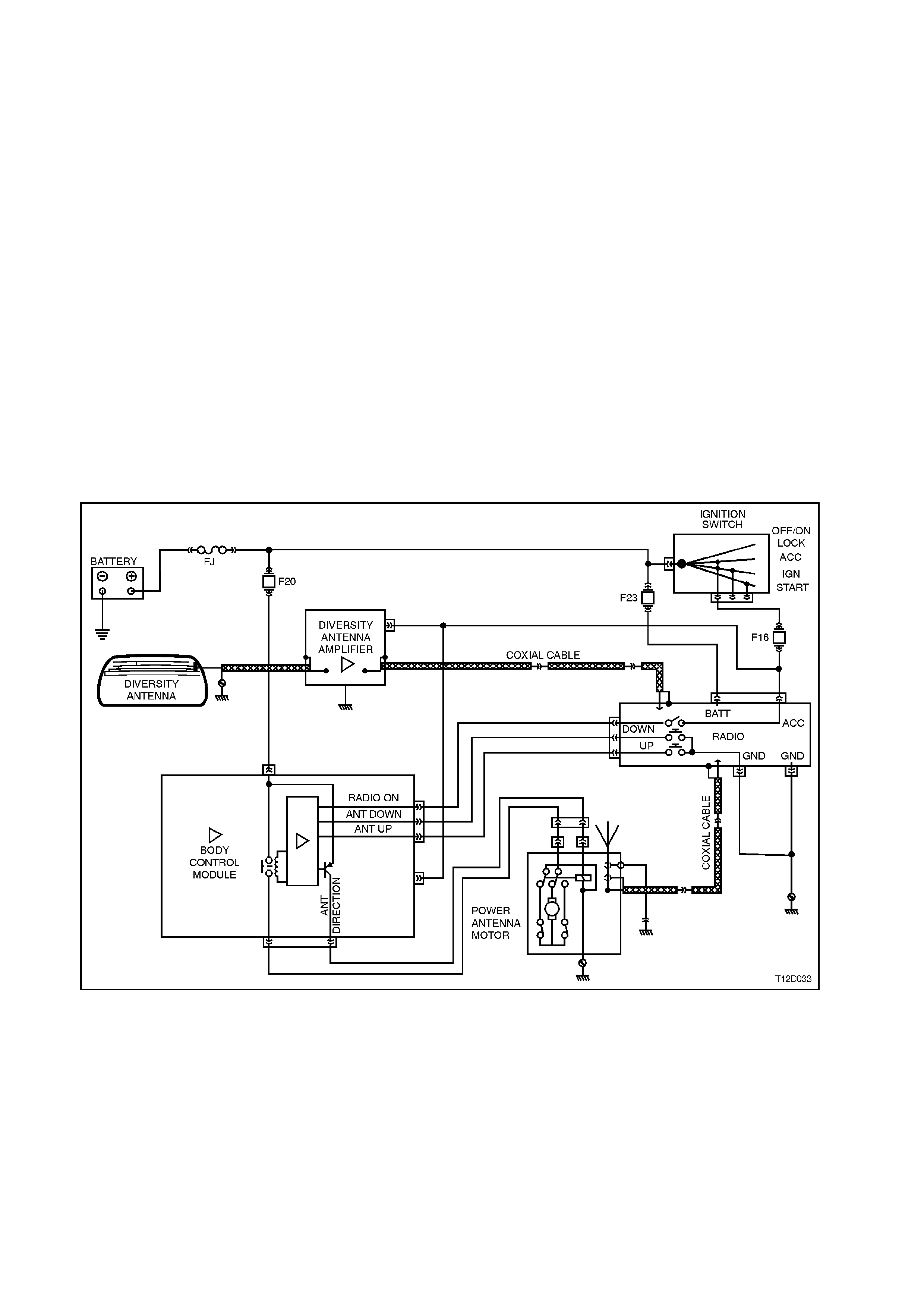
1.2 DIVERSITY ANTENNA OPERATION
To aid the consistent reception of FM radio signals, WH vehicles are equipped with a diversity antenna
system. This antenna system is designed to reduce the multipathing of FM radio signals in areas where the
signals are strongest. The antenna will not provide better reception in weak signal areas.
The diversity antenna system consists of a diversity antenna, diversity antenna module and coaxial leads.
The diversity antenna is an integral part of the rear window glass. The thin conductors that form the diversity
antenna are laid on the inside of the glass in the same manner as the rear window demister elements. A
terminal is located on the passenger side of the rear window allowing connection of the diversity antenna to
the diversity antenna module lead.
The diversity antenna module amplifies the signal received from the diversity antenna. It then transmits the
amplified signal to the radio’s diversity antenna input.
The diversity antenna module is located beneath the trim on the passenger side of the rear parcel shelf. The
module is connected to the diversity antenna via one of two coaxial leads, the other lead, located under the
passenger side rocker panel cover, connects the module to the radio’s diversity antenna input extension lead.
Another single wire lead is used to supply the diversity antenna module with 12 V for its operation and the
module is earthed through its case to the vehicle body.
To prevent interference, it is very important that the module and coaxial leads are earthed securely.
The radio receives signals from both the diversity antenna system and the conventional fender mounted mast
type antenna. Internal circuitry within the radio decides which antenna is located in the cleaner signal area. It
then uses that antenna for its radio reception.
When the vehicle is in motion the radio constantly monitors both antenna inputs and swaps between them in
order to maintain the best possible radio reception.
Figure 12D-4

1.3 HORN BAR STEREO CONTROL OPERATION
There are two major components of the horn bar
stereo control system. These components are as
follows:
1. Right-hand switch assembly –
Located to the right-hand side of the horn bar,
the right-hand switch assembly has three
momentary contact switches that are used to
control VOLUME and MUTE functions of the
stereo.
2. Left-hand switch assembly –
Located to the left-hand side of the horn bar,
the left-hand switch assembly has three
momentary contact switches that are used to
control NEXT UP, NEXT DOWN and MODE
selection.
OPERATION
When a button is pressed on the horn bar control,
the radio decides the function required by
measuring the resistance of the contact pressed.
Each control switch has a unique resistance value,
and this is used by the radio to determine which
command has been issued.
WH12D004
Figure 12D-5
1.4 ROOF MOUNTED REAR REMOTE CONTROL UNIT — CAP RICE
The roof mounted rear remote control unit has two
functions. First the rear remote provides control of
the audio system output in the same manner as the
steering wheel controls. Second, when the
headphones are connected to the output jacks, the
rear remote provides control of audio output
through the headphones by:
• Switch assemblies which control VOLUME,
MUTE, NEXT UP, NEXT DOWN and MODE
selection functions of the stereo.
OPERATION
Switch the audio system on and plug headphones
into one or both jacks adjacent to the child res traint
anchor point on the rear parcel shelf. Press a
button on the roof mounted rem ote control unit and
the radio will decide the function required by
measuring the resistance of the contact pressed.
Each control switch has a unique resistance value,
and this is used by the radio to determine which
command has been issued.
WH12D005
Figure 12D-6

WH12D017
AM/FMCD
SKIP
DSPEQ POS ON
123
6
54
BATTERY
30 OFF/ON
LOCK
ACC.
IGN.
START
15A 15 50
ECC
MODULE
R.H. STEERING
WHEEL SWITCH L.H. STEERING
WHEEL SWITCH
1k5 2k2 3k3 4k7 10k
VOLUME
DOWN VOLUME
UP MUTE MODEPRESET
NEXT DOWN PRESET
NE XT UP
REMOTE RADIO CONTROLS
REMOTE CLIMATE CONTROLS
ILLUMINATION
47
47
120
120
910
330
560
560
200
NEXT
LEFT
TEMP
DOWN
NEXT
RIGHT
TEMP
UP
VOLUME
DOWN
FAN
DOWN
VOLUME
UP
FAN
UP
MODE
B/Y BR
CLOCK
SPRING
COIL
F16
FJ R
Figure 12D-7
2. SERVICE OPERATIONS
2.1 RADIO/CASSETTE PLAYER
REMOVE
1. Disconnect battery earth cable.
2. Open left-hand side instrument panel lower
cover.
3. Open instrument panel compartment and
remove left-hand side lower trim assembly,
refer to Section 1A3 INSTRUMENT PANEL
AND CONSOLE in this Supplement.
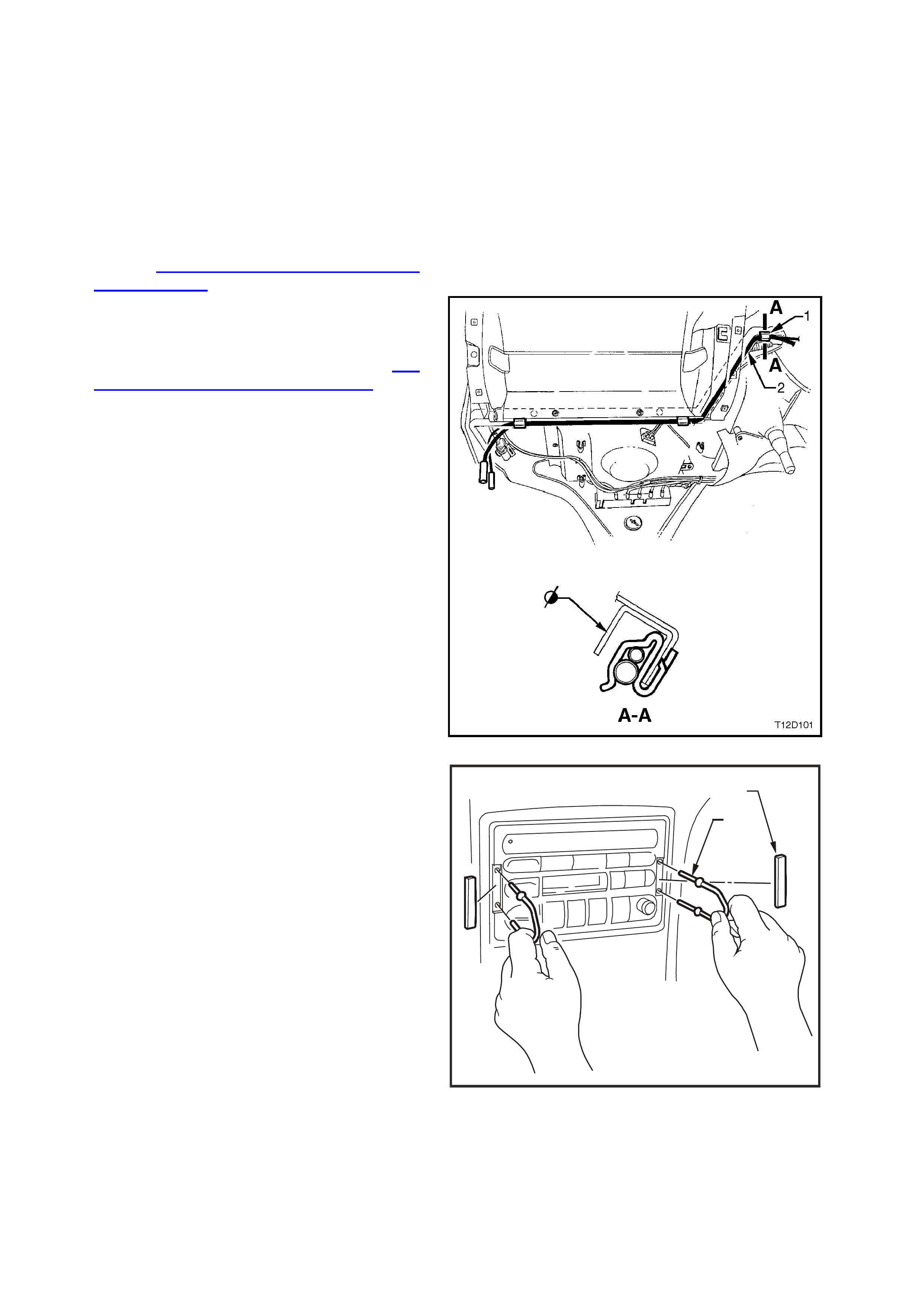
4. Unhook excess antenna lead (2) coiled thr ough
retaining clip (1) on right-hand side of
instrument carrier rail.
5. Remove centre console insert (refer to 1A3
INSTRUM ENT PANEL AND CONSOLE in this
Supplement.
6. Remove capping from around radio by
removing screws securing lower capping to
console, then carefully prising capping away
from panel.
Figure 12D-8
7. Carefully prise snap-on-covers (2) from radio
removal holes, then using special service tool
(1) No. 179 1308 0000, insert into removal
holes on either side of radio/cassette player
and push service tool in to release retaining
sprin g clips.
8. Pull radio/cassette player out sufficiently to
access wiring harness and antenna connectors
at rear of unit.
1
2
WH1A3005
Figure 12D-9
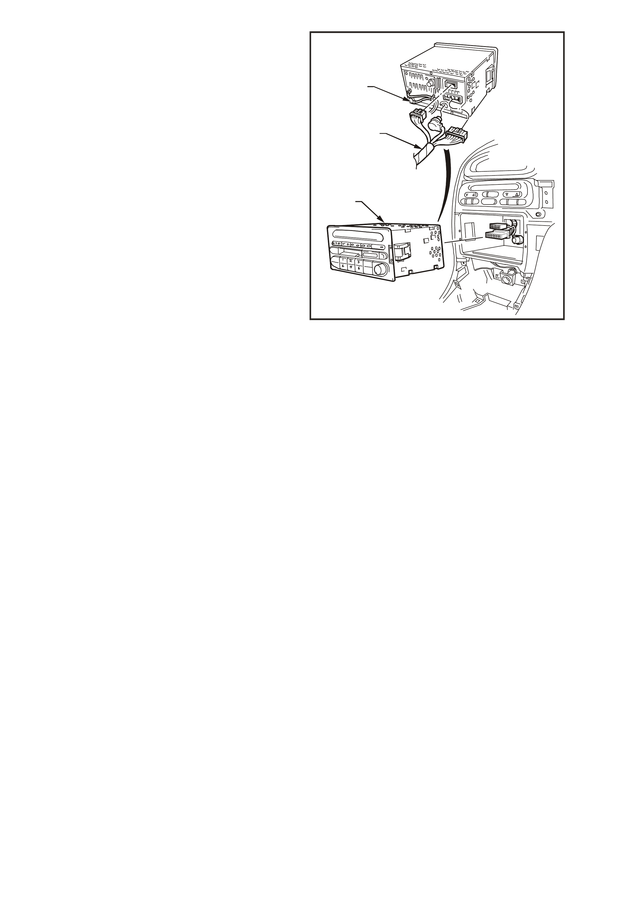
9. Disconnect radio/cassette wiring harness (1)
and CD connectors.
10. Release antenna leads (2) from flexible tab on
rear of radio.
11. Disconnect mast antenna and divers ity antenna
connections (2) from rear of radio/cassette
player and remove the radio/cassette player
(3).
WH1A3006
2
1
3
Aasdff
AasdffAasdff
Hfuedkck
H
fuedkck
Hfuedkck
Hfuedkck
Hfuedkck
Hfuedkck
Hfuedkck
Hfuedkck
Hfuedkck
Hfuedkck
Hfuedkck
HfuedkckHfuedkck
Figure 12D-10
REINSTALL
Installation is the revers e of the rem oval procedure
noting the following:
1. Ensure antenna leads are secured by flexible
tab on rear of radio.
2. Locate wiring and antenna leads from behind
radio carrier and gently pull all leads from
behind, while sliding radio into position.
NOTE: This is necessary to ensure that none of
the leads are jammed or damaged behind the
radio.
If care is not taken antenna lead may be
crushed between radio and radio carrier,
causing intermittent reception problems.
3. Check for correct operation.
2.2 FRONT INSTRUMENT PANEL SPEAKERS – ALL MODELS
REMOVE
1. Disconnect battery earth cable.
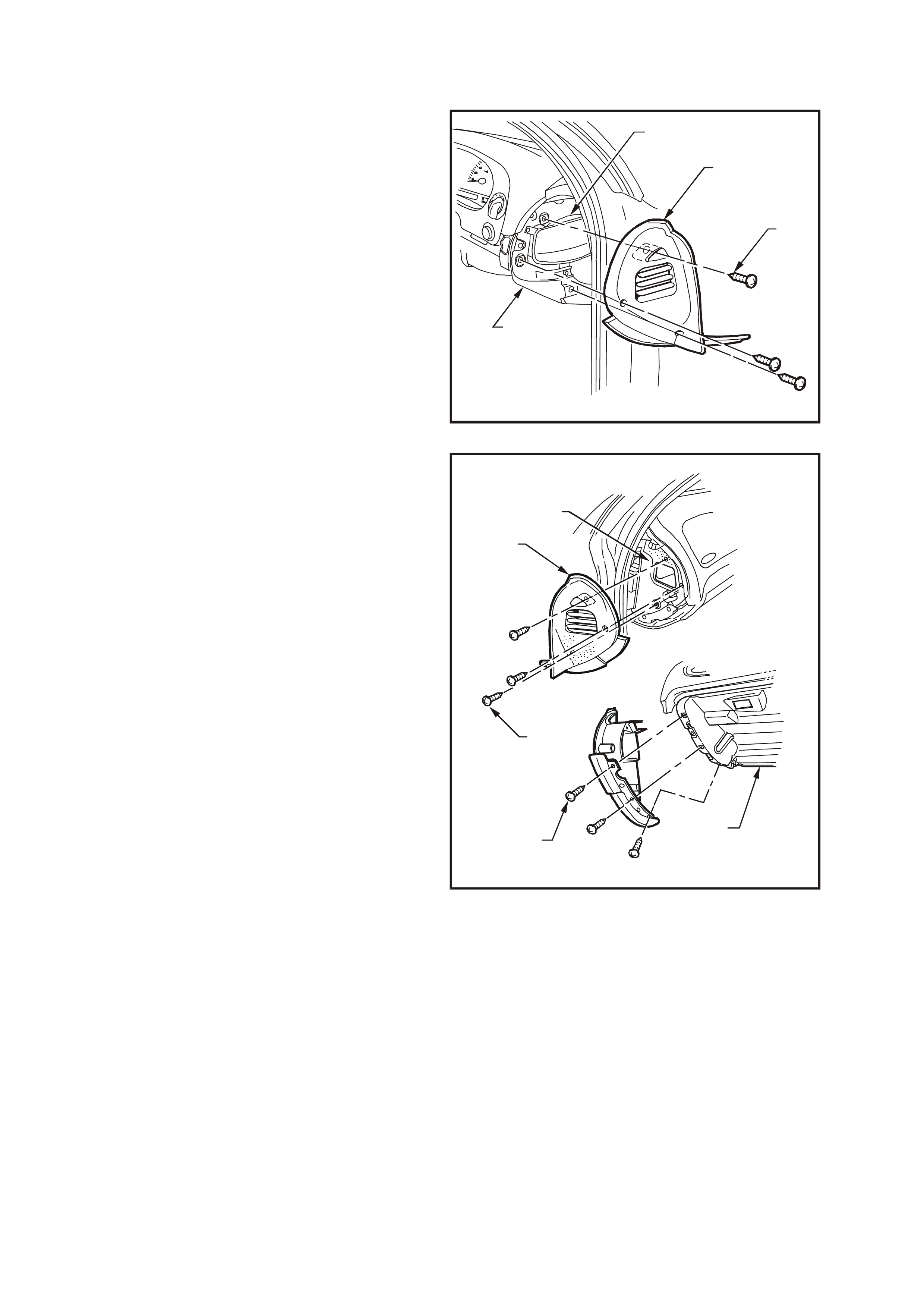
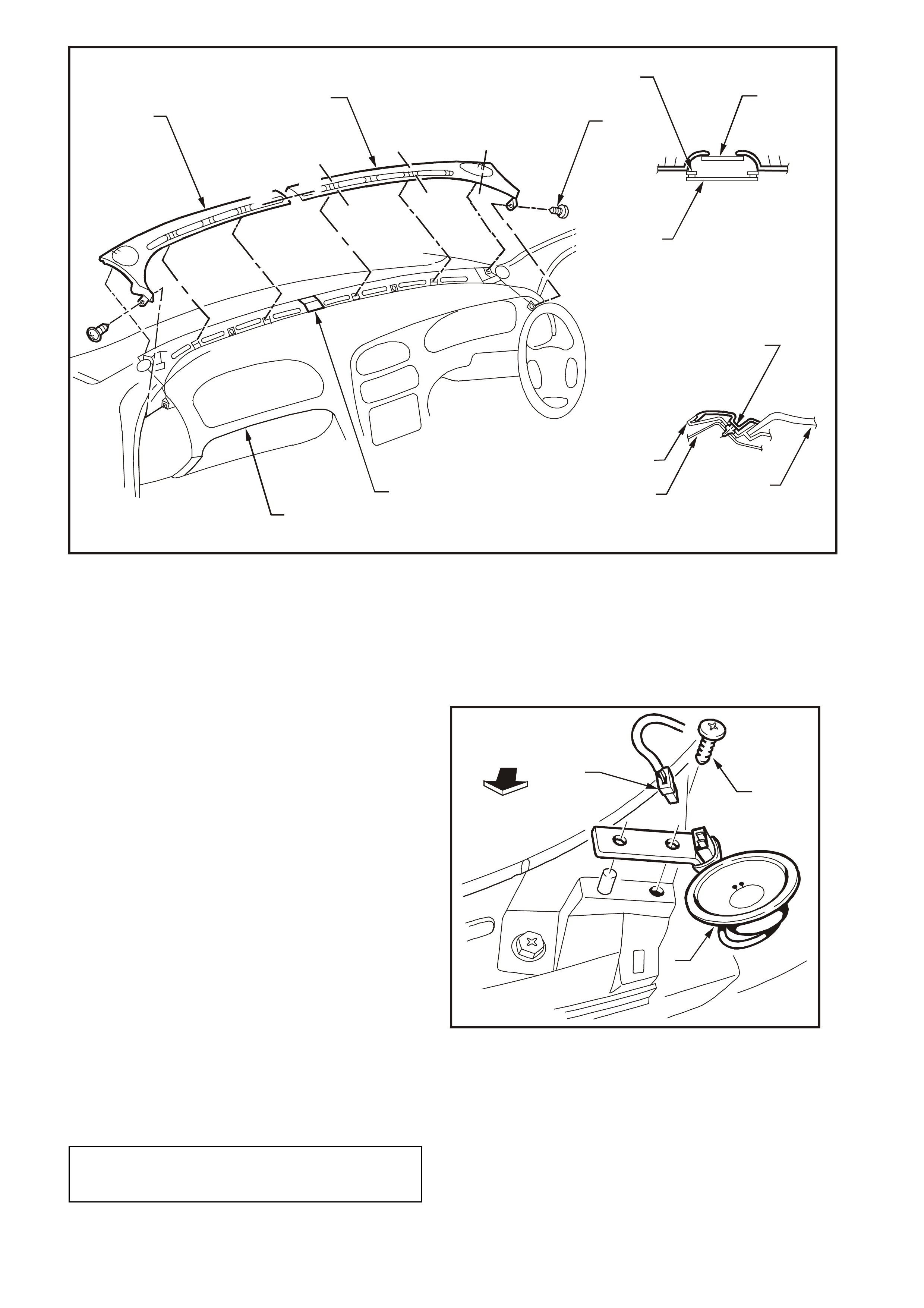
2. Remove the three screws (1) securing right-
hand side instrument panel end-cap cover (2)
to instrument carrier (3) and steering column
outer bracket (4) and remove instrument panel
end-cap cover (2).
WH1A3013
3
2
1
4
Figure 12D-11
3. Remove the six retaining screws (1 and 2)
securing left-hand side instrument panel end-
cap cover (3) to instrument panel carrier (4)
and instrument panel roof (5). Remove
instrument panel end-cap cover (3).
4. Remove retaining screw from the demist nozzle
right-hand and remove.
5. Remove retaining screw from the demist nozzle
left-hand and remove.
NOTE: On all vehicles , c are mus t be taken to avoid
damage to the solar sensor (if fitted).
WH1A3014
2
1
3
4
5
Figure 12D-12
WH1A3019
A
A
A
A
A
A
BB
B-B
A-A
8
910
7
6
4
3
2
1
12 11
5
Figure 12D-13
1. Demist Nozzle Grille left-hand side
2. Demist Nozzle Grille right-hand side
3. Screw (1 place right and left side)
4. Instrument Panel Pad Carrier
5. Solar Sensor
6. Instrument Panel Pad Carrier
7. Tabs to be inserted into holes in
instrument panel pad carrier before
installation of right and left side
attaching screws
8. Demist Grille Seal
9. Instrument Panel Pad Carrier
10. Instrument Panel Upper Pad
Assembly
11. Solar Sensor
12. Instrument Panel Pad Assembly
6. Disconnect left and right front dash speaker
harness connectors (1). Using a Phillips head
screw driver, rem ove screws (2) attac hing front
dash speakers (3) and remove both speakers
(3).
NOTE: The connector locking tab may be hidden
under the tie strap.
2
1
3
WH12D006
Figure 12D-14
REINSTALL
Installation is the reverse of the r emoval proc edure.
Tighten speaker screws to the specified torque.
FRONT INSTRUMENT PANEL
SPEAKERS
ATTACHING SCREWS 1 – 2 Nm
2.3 FRONT DOOR SPEAKERS – ALL MODELS
REMOVE
1. Remove door trim from front door. Refer to
Section 1A5 FRONT AND REAR DOOR
ASSEMBLIES in this Supplement.
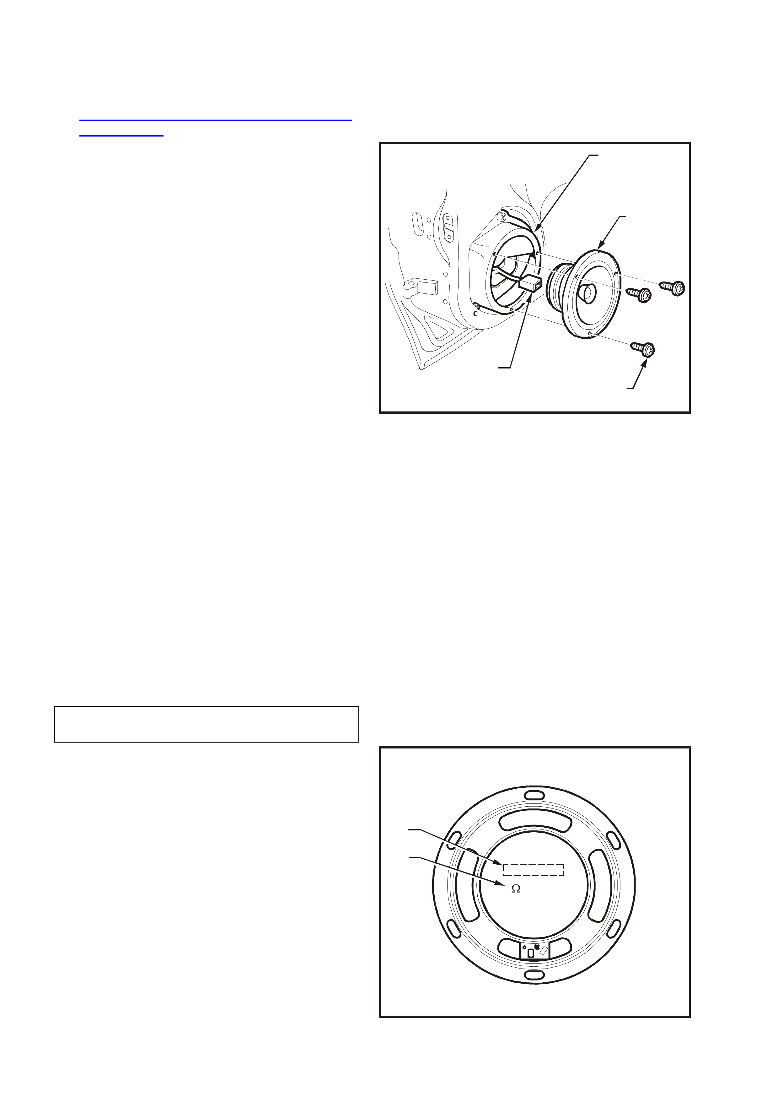
2. Remove speaker assembly to speaker box
attaching screws (4).
3. Remove speaker (2) from speaker box (1).
Release wiring harness from tab on rear of
speaker box (1).
Disconnect wiring harness connector (3) from
speaker and remove speaker.
WH12D019
3
4
2
1
Figure 12D-15
REINSTALL
Installation is the reverse of the removal procedure
noting the following:
1. Ensure electric al c onnector is proper ly attached
to speaker.
2. Before installing speaker, visually inspect
speaker mounting box cavity for protrusions
that will touch the underside of the speaker
cone on installation, i.e. cable ties etc. Secure
wiring harness to tab on rear of speaker box.
3. Carefully install speaker attaching screws
ensuring that speaker frame is not distorted
when screws are tightened.
NOTE: Angled insertion of speaker attaching
screws can lead to speaker distortion. Make sure
screws are installed square to speaker frame.
NOTE: There are specific front and rear speaker
assemblies for WH Series vehicles. Refer to
Fig. 12D-16 for identification details. Chec k that the
part number (1) and resistance values (2) are the
same as those on the speaker being replaced, as
incorrect speaker fitment can affect system
operation, resulting in unnecessary complaints.
Check speaker operation once installation has
been completed.
WH12D020a
1
2
30W
CHINA
7337
2
Figure 12D-16
FRONT DOOR SPEAKER
ATTACHING SCREWS 1 – 3 Nm

2.4 REAR DOOR SPEAKERS
REMOVE
1. Remove door trim from rear door. Refer to
Section 1A5 FRONT AND REAR DOOR
ASSEMBLIES in this Supplement.
2. Remove three screws (4) securing speaker
assembly (2) to speaker box (1).
3. Remove speaker from speaker box.
Release wiring harness from tab on rear of
speaker box (1).
Disconnect wiring harness connector (3) from
speaker and remove speaker.
WH12D007
1
2
3
4
Figure 12D-17
REINSTALL
Installation is the reverse of the removal procedure
noting the following:
NOTE: There are specific front and rear speaker
assemblies for WH Series vehicles. Refer to Fig.
12D-16 for identification details . Check that the part
numbers and resistance values are correct, as
incorrect speaker fitment can affect system
operation, resulting in unnecessary complaints.
1. Ensure electrical connector (3) is properly
attached to speaker (2).
2. Before installing speaker, visually inspect
speaker mounting box cavity for protrusions
that will touch the underside of the speaker
cone on installation, ie. Cable ties etc.
Resecure wiring harness to tab on rear of
speaker box (1).
3. Carefully install speaker attaching screws
ensuring that speaker frame is not distorted
when screws are tightened.
NOTE: Angled insertion of speaker attaching
screws can lead to speaker distortion. Make sure
screws are installed square to speaker frame and
are tightened to the correct torque specification.
Check speaker operation once installation has been
completed.
REAR DOOR SPEAKER
ATTACHING SCREWS 1 – 3 Nm
2.5 SUBWOOFER SPEAKERS
REMOVE
1. Disconnect battery earth cable.
2. Remove rear seat cushion and back
assemblies, refer to Section 1A7 SEATS AND
SEAT BELT ASSEMBLIES in this Supplement.
3. Remove the centre seat belt lower attachment,
refer to Section 1A7 SEATS AND SEAT
BELT ASSEMBLIES in this Supplement.
4. Open flap to child restraint fitting and unbolt
child restraint fitting.
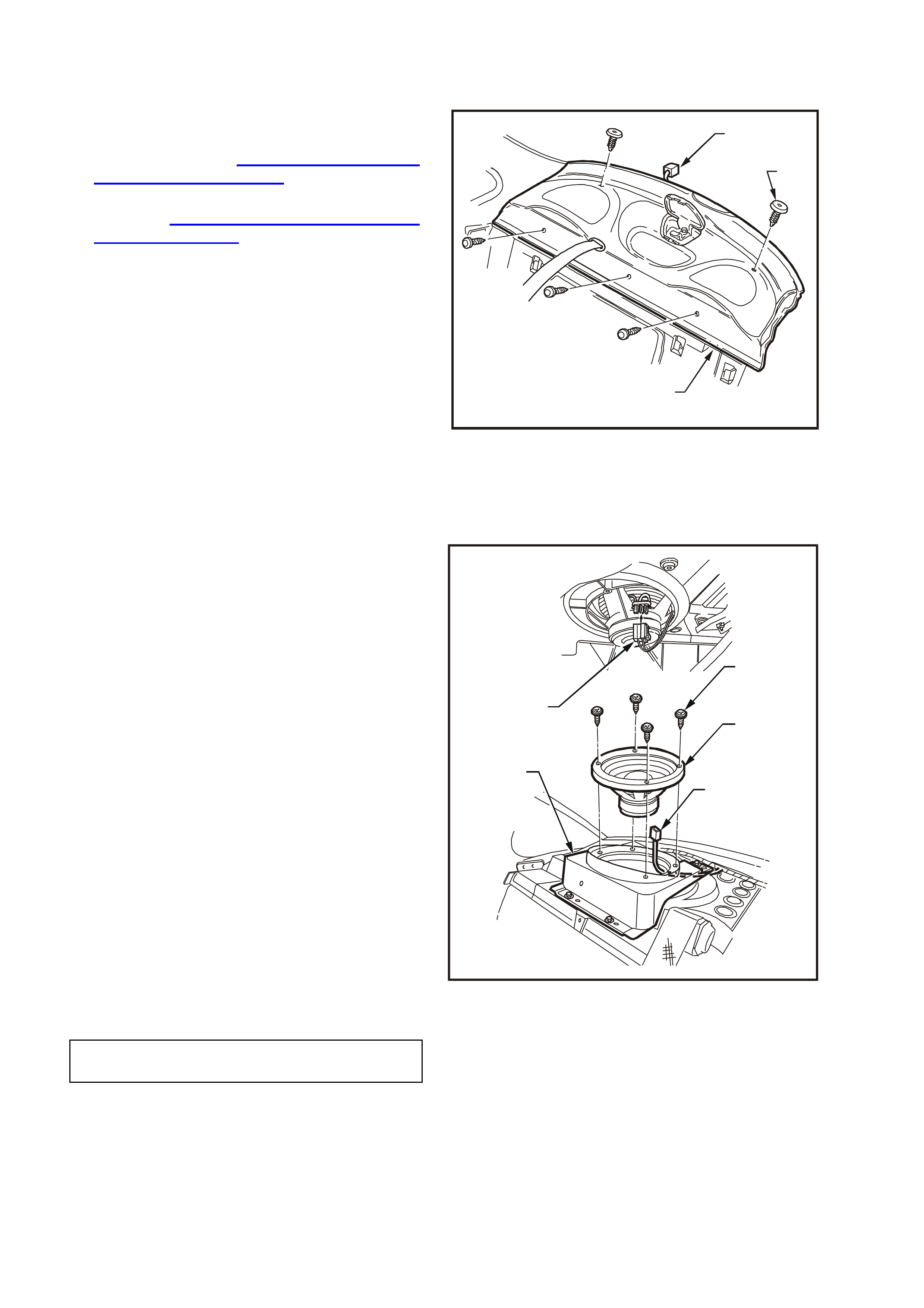
5. From the rear compartment, carefully tap out
the fir-tr ee fasteners (2) secur ing the trim ( 3) to
the rear parcel shelf.
6. From within passenger compartment, remove
three screws securing the trim to the rear seat
support.
7. Disass em ble webbing guide (unclip from par cel
shelf).
8. Pull flap in parcel shelf forward, feed seatbelt
tongue and anchor through hole.
9. Disconnect headphone jack connector (1) from
body wiring harness connector and remove
parcel shelf trim.
3
1
2
WH12D008
Figure 12D-18
10. From the rear compartment, carefully remove
wiring harness connections (3) to left-hand s ide
and right-hand side subwoofers.
11. From within passenger compartment, remove
four screws (1) securing each subwoofer (2)
and carefully lift from mounting bracket (4).
REINSTALL
Installation is the reverse of the rem oval procedure
noting the following:
1. Ensure elec trical c onnector is properly attached
to speaker.
2. Before installing speaker, visually inspect
speaker mounting box cavity for protrusions
that will touch the underside of the speaker
cone on installation eg. Cable ties.
3. Carefully install speaker attaching screws
ensuring that speaker frame is not distorted
when screws are tightened.
When installing parcel shelf trim, take care to
ensure that foam sealing ring has not become
dislodged or folded back on itself.
NOTE: Angled insertion of speaker attaching
screws can lead to speaker distortion. Make sure
that screws are installed square to speaker frame.
WH12D018
1
2
3
3
4
Figure 12D-19
SUBWOOFER SPEAKER
ATTACHING SCREWS 1 – 3 Nm
2.6 ROOF MOUNTED SPEAKERS – CAPRICE
REMOVE
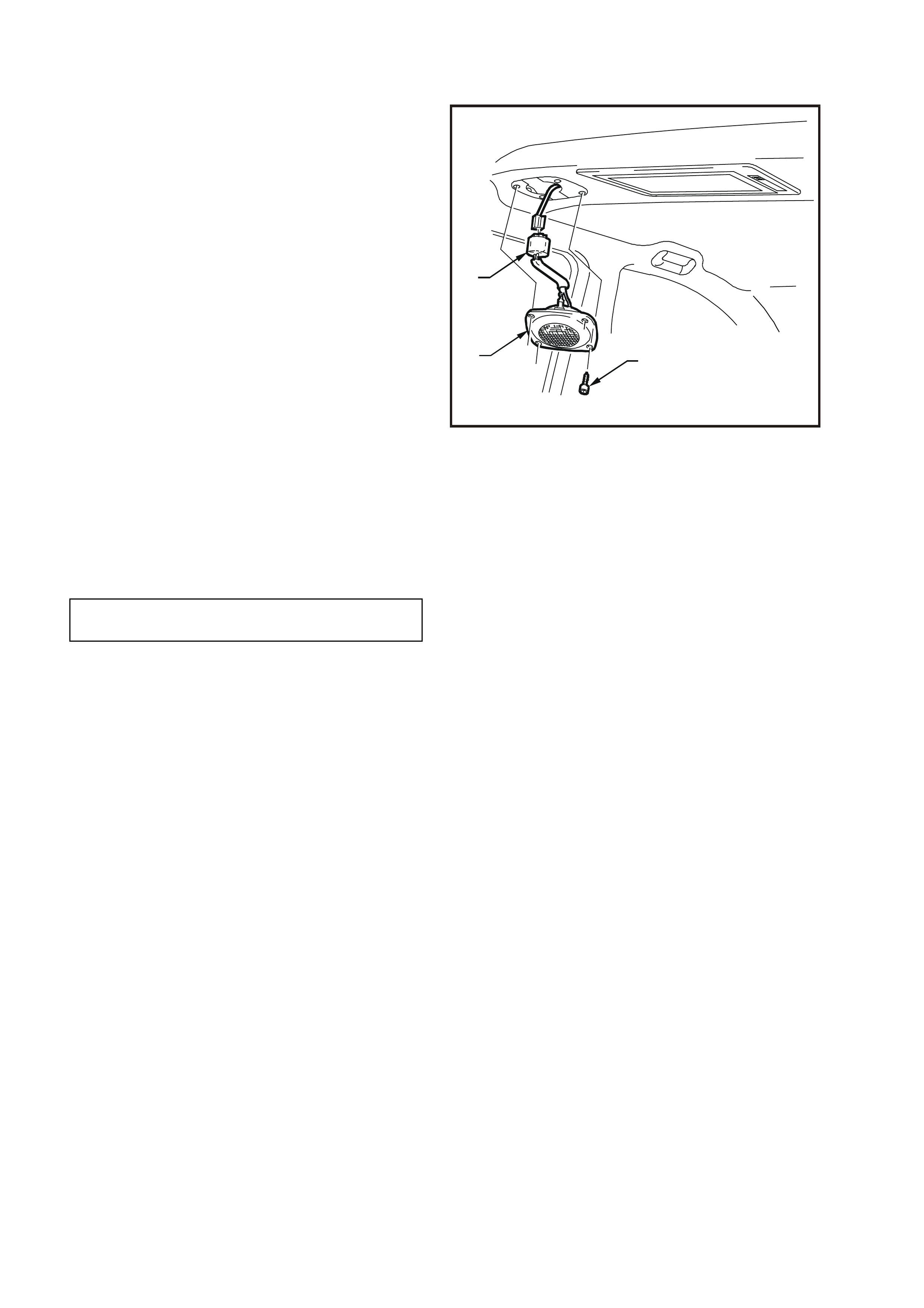
1. Remove f our attaching scr ews ( 3) from fr ont of
speaker assembly.
2. Car efully remove speak er (2) fr om roof console
to avoid damaging, on the mounting bracket,
the insulating boots covering the terminals.
3. Disconnect wiring harness connector (1) from
speaker and remove speaker.
REINSTALL
Installation is the reverse of the removal procedure
noting the following:
1. Ensure electrical connector is properly attached
to speaker.
2. Before installing speaker, visually inspect
speaker mounting cavity for protrusions that will
touch the underside of the speaker cone on
installation and rectify.
3. Ensure that the insulating boots are correctly
installed over the terminals at the speaker and
are not damaged. Replac e the insulating boots if
necessary.
4. Carefully install speaker attaching screws
ensuring that speaker frame is not distorted
when screws are tightened to specified torque
NOTE: Angled insertion of speaker attaching
screws can lead to speaker distortion. Make sure
screws are installed square to speaker frame.
3
2
1
WH12D025
Figure 12D-20
ROOF MOUNTED SPEAKER
ATTACHING SCREWS 1 – 3 Nm
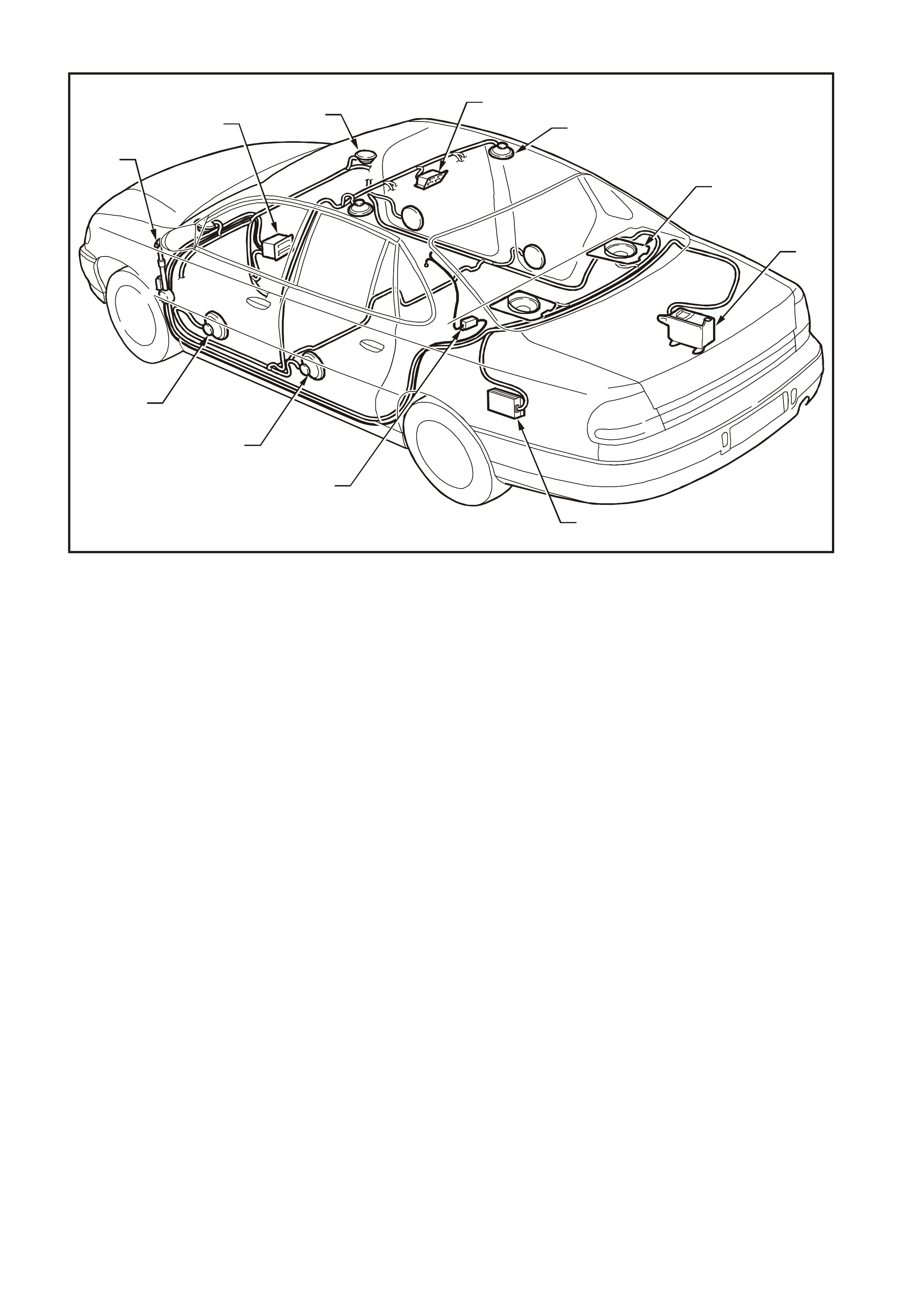
2.7 AUDIO SYSTEM WIRING
WH12D009
7
8
9
10
11
4
6
5
3
1
2
Figure 12D-
1. Power Antenna 7. CD Changer
2. Radio/Cassette/CD Unit 8. Subwoofer Amplifier
3. Front Instrument Panel Speaker 9. Diversity Antenna Amplifier
4. Roof Mounted Rear Remote Control (Caprice) 10.Rear Door Speaker
5. Roof Mounted Rear Speaker 11.Front Door Speaker
6. Subwoofer Speaker
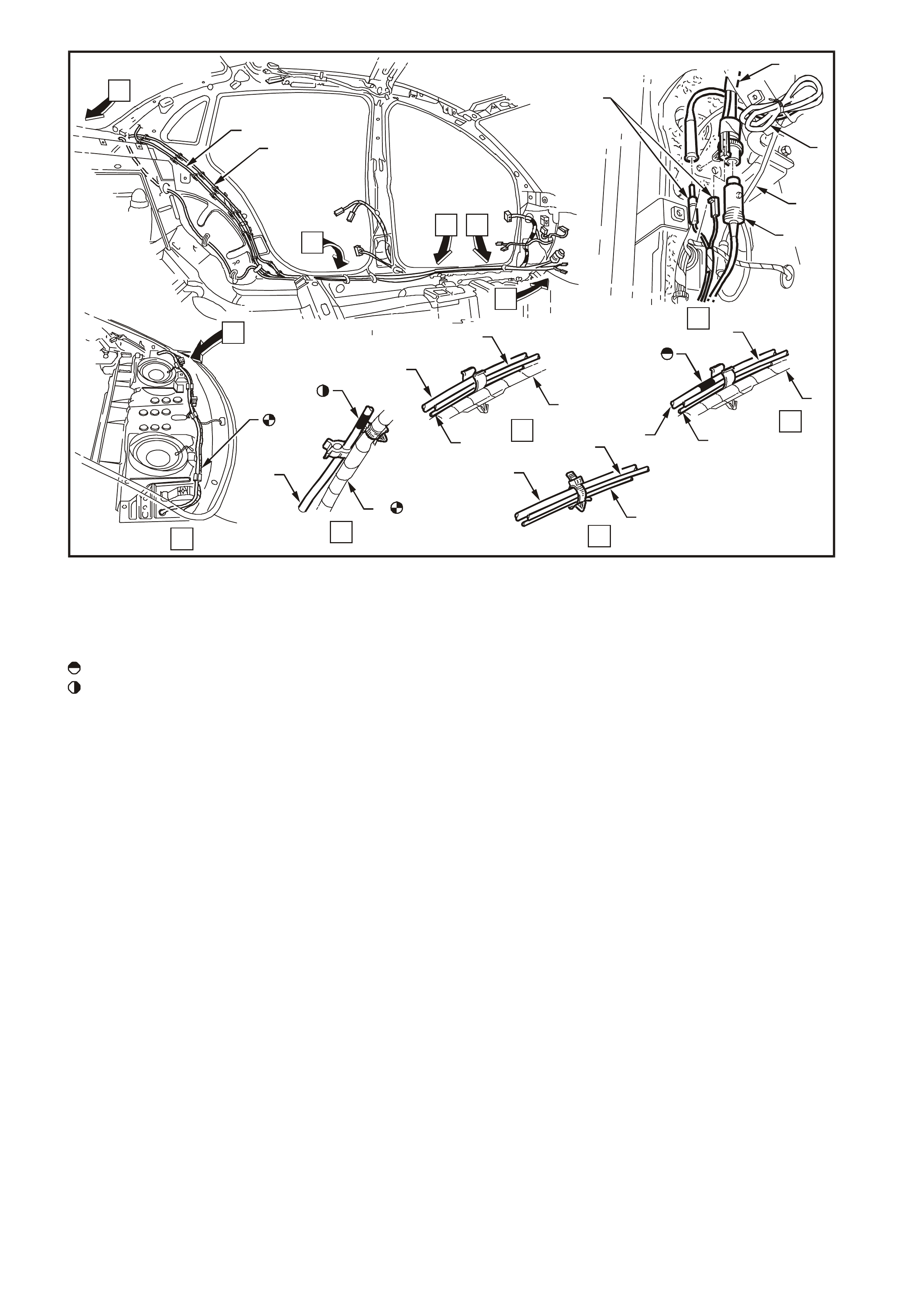
WH12D010
A
A
CB
D
E
D
F
2
4
1
6
3
12
C
2
6
1
B
6
2
1
5
E
2
1
5
6
F
6
5
Figure 12D-22
1. Phone Antenna Lead 4. Power Antenna
2. Diversity Antenna Lead 5. Body Wiring Harness
3. Main Wiring Harness 6. CD Harness
: Align white tape mark on CD harness with forward most clip.
: Align white tape mark on CD harness with cable clip as shown.
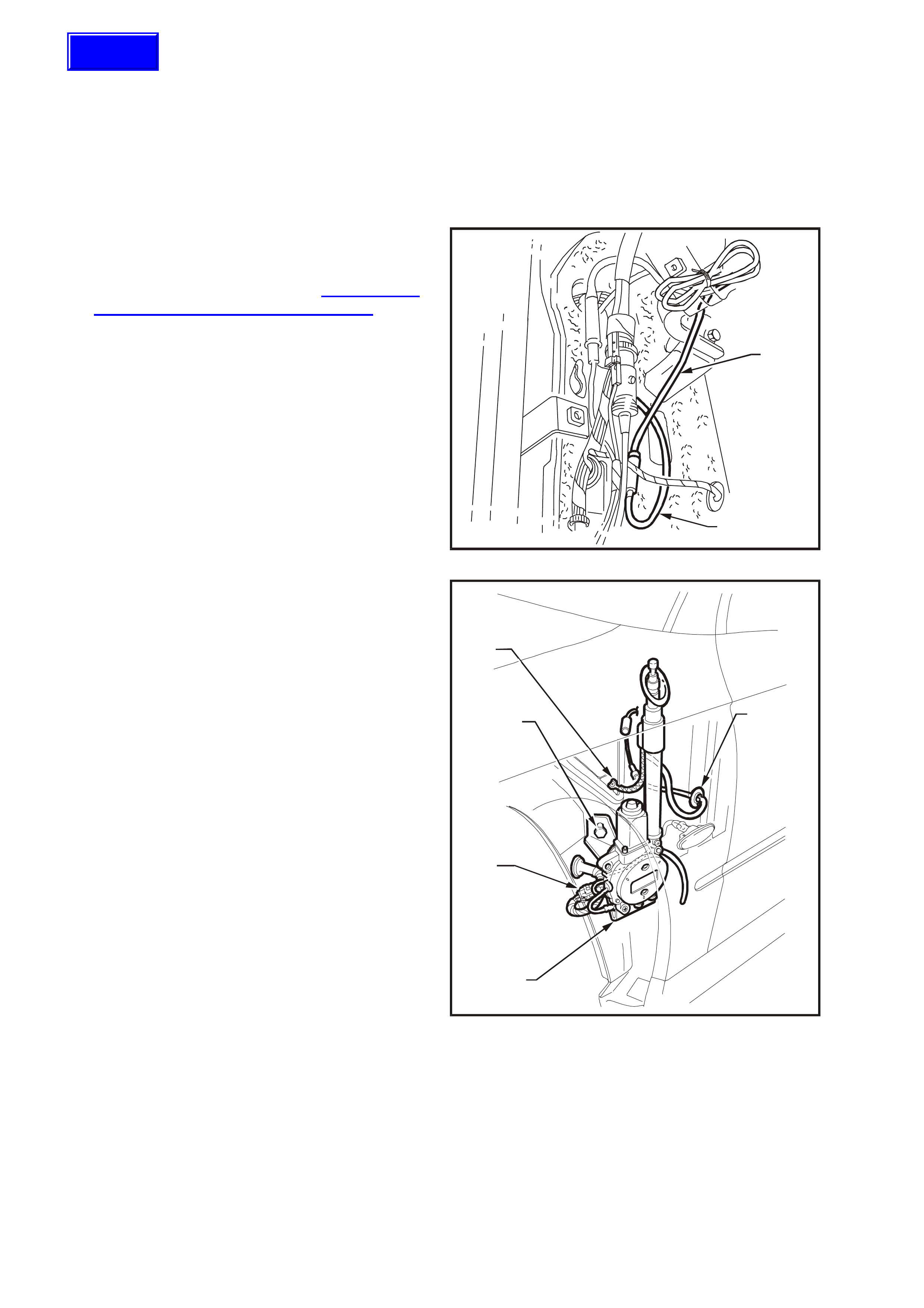
2.8 POWER ANTENNA
POWER ANTENNA SWITCHES
The power antenna direc tional control switches ar e
integrated with the radio and as such cannot be
serviced separately.
POWER ANTENNA ASSEMBLY
REMOVE
1. From inside vehicle, remove footwell upper
closing panel left side, instrument panel
compartment and instrument panel
compartment roof, refer to Section 1A3
INSTRUM ENT PANEL AND CONSOLE in this
Supplement.
2. Disconnect antenna lead ( 2) from antenna lead
extension (1) at connecting socket above
powertrain control module at left-hand cowl
panel.
WH12D011
1
2
Figure 12D-23
3. Set antenna mast to fully retracted position.
4. Remove nut, retainers and screws securing
left-hand fender inner liner and remove inner
liner.
5. Remove screw connecting earth braid (1) to
inner fender earth terminal.
6. Disconnect antenna wiring harness
connector (2) from main wiring harness
connector in wheel well.
7. While supporting antenna assembly, remove
antenna support bracket attaching bolt (3).
8. Remove antenna lead grommet (4) from inner
fender panel and pull lead out from passenger
compartment.
9. Withdraw antenna (5) down through bezel and
remove, complete with leads, grommet and
bracket.
WH12D021
5
2
3
1
4
Figure 12D-24
REINSTALL
Installation is the revers e of the rem oval procedure
noting the following:
1. Ensure cable and harness are routed correctly.
2. Ensure that antenna and earth leads are routed
correctly and securely connected.
3. W ith antenna pushed up against stop in bezel,
tighten antenna bracket to inner fender panel
attaching bolt to the correct torque
specification.
Techline

ANTENNA BRACKET TO
INNER FENDER BOLT
TORQUE SPECIFICATION 5.0 – 12.0 Nm
4. Check antenna operation and radio reception.
MAST REPLACEMENT
The following procedure is for replacing a damaged
or faulty antenna mast and drive cable assembly.
1. Remove power antenna assembly as
previously described in this Section.
2. Remove chrome plated nut from top end of
mast tube.
3. Extend damaged antenna mast as far as
possible by attaching battery negative via a
jumper lead to antenna mounting bracket and
battery positive to both the antenna red and
white wire terminals.
At end of mast travel, pull out mast and drive
cable from antenna housing.
NOTE: If mast is too badly damaged to extend,
grip tip of mast with a pair of pliers and pull mast
and drive cable ass embly up and out from antenna
housing.
4. If necessary, remove contact spring (metal
sleeve) from old mast and drive cable and
install onto replacement mast and drive cable.
5. Feed end of drive cable down mast tube of
antenna housing with serrated side of drive
cable facing toward the centre of the housing.
Continue to feed drive cable down until it
engages with the drive mechanism.
NOTE: It may be necessary to twist the drive cable
clockwise and anti-clockwise slightly to enable end
of cable to feed through opening at base of mast
tube before it engages the drive mechanism.
6. With the aid of an ass istant to hold the antenna
and mast assembly, connect antenna mounting
bracket via a jumper lead to battery negative.
7. Momentarily connect battery positive to the
antenna red wire and drive mechanism should
start to retract drive cable into antenna
housing.
8. With the drive cable engaged to drive
mechanism, reconnect battery positive to
antenna red wire and allow drive mechanism to
wind in drive cable and mast into mast tube
and housing.
9. At this stage the mast might be fully retracted
into the mast tube and housing. Reconnect
both the red and white wires to battery positive
and allow the mast to extend fully until the
motor stops.
Disconnect white wire from battery positive and
allow mast to fully retract.
10. Install chrome plated nut to top end of mast
tube and tighten securely.
11. Install power antenna assembly as previously
described in this Section. Check antenna m ast
operation.

CHECKING ANTENNA MOTOR OPERATION
NOTE: The following Checking Antenna Motor
Operation tests are made at the main wiring
harness to antenna motor connector located in the
right-hand fender.
The voltages shown are measured to a good ear th
point on the vehicle body.
Voltage on antenna
harness wires
Red White Action
12 V 12 V Antenna extends
12 V 0 V Antenna retracts
0 V 12 V Antenna does not move
0 V 0 V Antenna does not move
If the antenna motor does not correctly respond to
the inputs as specified, ensure that a good earth
connection is being made through the mounting
bracket by measuring the resistance from the
bracket to a good earth point. If more than 1 ohm
replace power antenna assembly. Check that the
forked earth connector is securely attached to the
antenna mounting.
NOTE: If there is significant noise on the AM band
(with radio tuned to weak station outdoors), then
check antenna earth quality. The antenna earth
terminal has a large effect on the screen.

2.9 DIVERSITY ANTENNA
The divers ity antenna is an integral part of the rear
window assembly. The thin conductors that form
the diversity antenna are laid on the inside of the
rear window glass in the same manner as the
heated rear window elements.
A single terminal is located on the ins ide of the r ear
window glass, on the passenger side, to allow
connection of the diversity antenna to the diversity
antenna module, located under the rear parcel
shelf trim.
The diversity antenna module amplifies the radio
signal received by the diversity antenna and
transmits it to the radio/cassette player via coaxial
cable.
NOTE: Due to the internal circuitry of the radio
receiver, if the fender mounted mast antenna is
retracted, faulty or disconnected, the radio m ay not
use the diversity antenna system for radio
reception if the FM signal is weak.
DIVERSITY ANTENNA — TEST
1. Disconnect diversity antenna module connector
from diversity antenna terminal.
2. Using an ohmmeter measure the resistance
from the diversity antenna terminal to the
diversity antenna conductors on the inside of
the rear window glass.
Resistance should be less than 20 ohms from
diversity antenna connector to any point on the
diversity antenna conductors.
NOTE: Care should be taken when measuring
resistance that the diversity antenna conductors
are not damaged by the use of excessive force on
the ohmmeter probe.
DIVERSITY ANTENNA MODULE
REMOVE
1. Remove rear seat cushion and back
assemblies, refer to Section 1A7 SEATS AND
SEAT BELTS in this Supplement.
2. Rem ove rear parcel shelf trim and side quarter
window trim, refer to Section 1A8
HEADLINING & REAR END TRIM in this
Supplement.
3. Rem ove passenger side lower shroud tr im and
rocker panel cover, refer to Section 1A1
BODY in this Supplement.
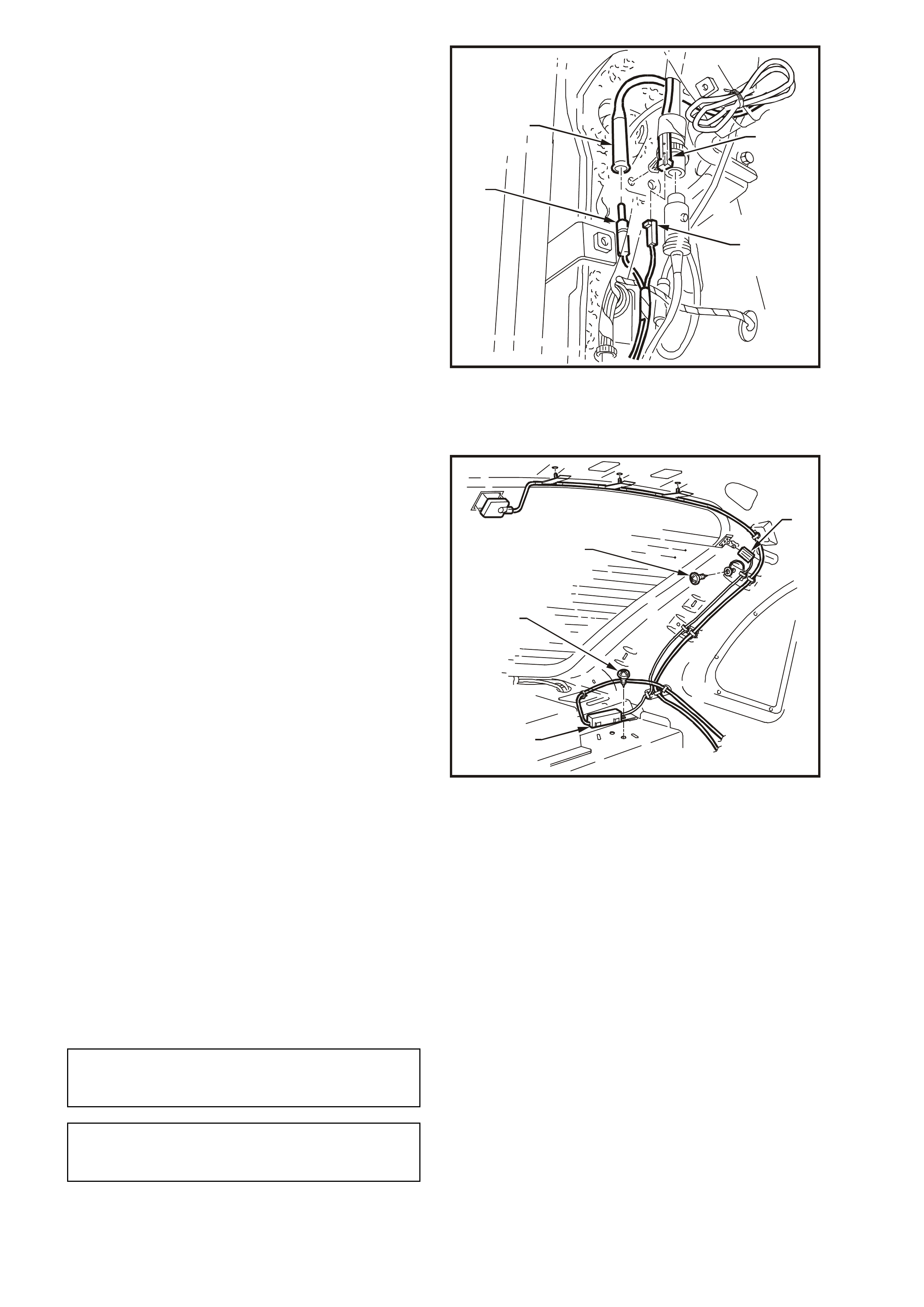
4. Disconnect diversity antenna module harness
connector ( 1) f r om cor res ponding c onnector ( 2)
on main wiring harness located near the PCM.
5. Disconnect diversity antenna module coaxial
cable (3) from radio diversity antenna extension
cable connector (4) located near PCM.
WH12D012
1
2
3
4
Figure 12D-25
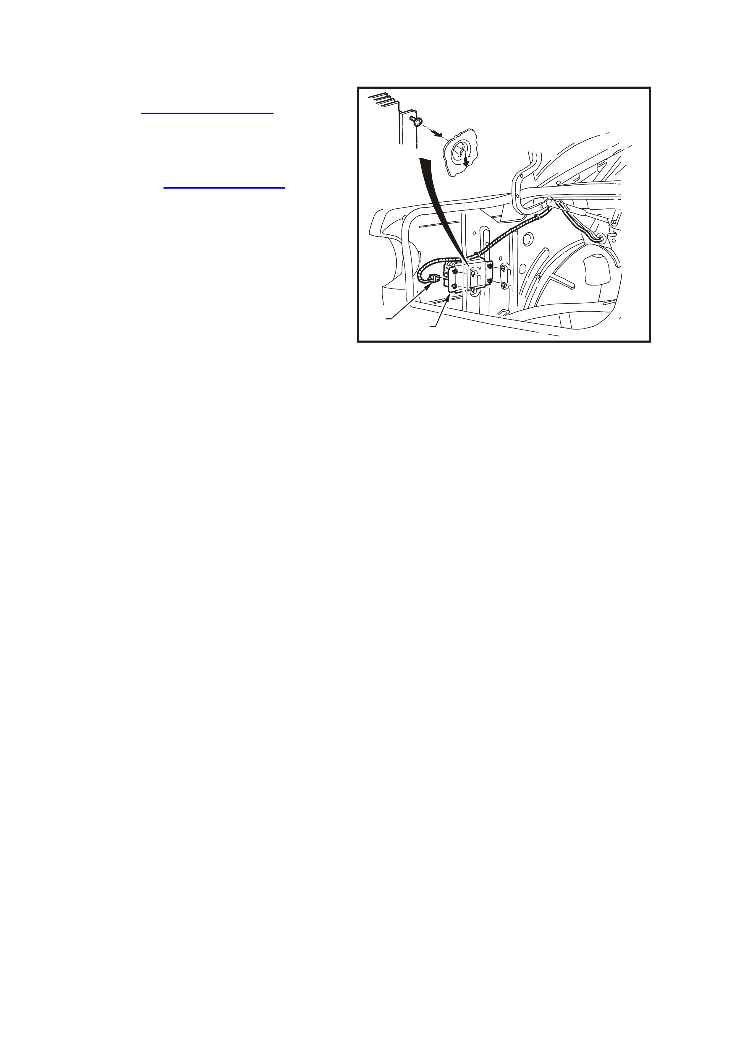
6. Remove diversity antenna module leads from
retaining clips and remove leads from rocker
panel.
7. Remove diversity antenna module connector
(1) from diversity antenna terminal located on
rear window.
8. Remove screw (4) securing diversity antenna
earth terminal to vehicle body.
9. Remove screw (3) securing diversity antenna
amplifier to rear parcel shelf. Remove diversity
antenna module (2) and leads.
WH12D013
1
2
3
4
Figure 12D-26
REINSTALL
Installation is the reverse of the removal procedure
noting the following:
1. Ensure that locating tag on diversity antenna
module is correctly engaged into the mounting
slot on the rear parcel shelf.
NOTE: After connecting diversity antenna module
connector (1) to diversity antenna, ensure to bend
the tab in direction shown in Fig 12D-26.
Tighten diversity antenna module mounting
screw to the correct torque specification.
DIVERSITY ANTENNA
MODULE EARTHING SCREW
TORQUE SPECIFICATION 1 – 3 Nm
DIVERSITY ANTENNA
MODULE MOUNTING SCREW
TORQUE SPECIFICATION 1 – 3 Nm
2.10 HORN BAR STEREO CONTROLS
The horn bar stereo control system consists of two
control switch assemblies which are located on
each side of the driver’s side air bag and a radio
connection.
The horn bar s ter eo contr ols utilise the clock s pr ing
coil harness as a data link to the radio.
REMOVE
CAUTION: Disable the SRS (Air Bag). Refer to
DISABLING THE SRS, Section 12M
SUPPLEMENTAL RESTRAINT SYSTEM of the
VT Series I Service Information.
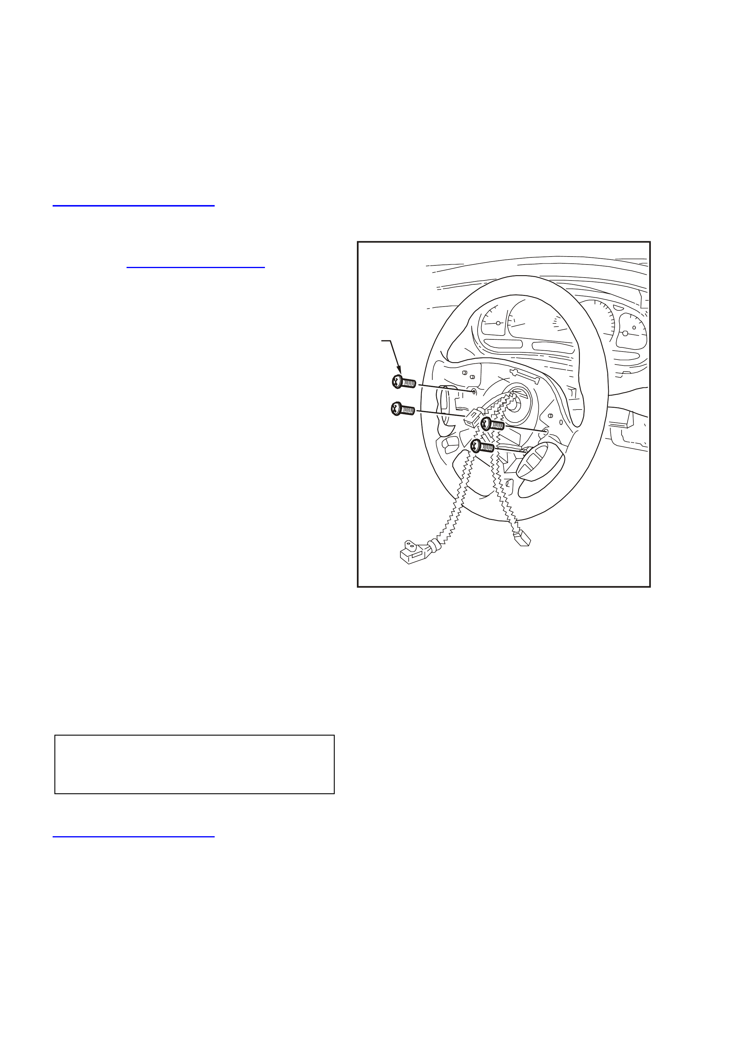
1. Rem ove air bag assem bly from s teering wheel,
refer to Section 9A STEERING of the VT
Series I Service Information.
2. Disconnect horn bar stereo control harness
from steering column harness connector.
3. Remove horn bar stereo switch assembly to
steering wheel attaching screws (1) and
remove horn bar stereo switch assembly.
NOTE: The horn bar stereo switch assembly
consists of two switch blocks connected together
by a wiring harness.
WH12D022
1
Figure 12D-27
REINSTALL
Installation is the revers e of the rem oval procedure
noting the following.
1. Tighten horn bar stereo switch assembly to
steering wheel attaching screws to the correct
torque specification.
STEREO SWITCH TO
STEERING WHEEL
ATTACHING SCREW
TORQUE SPECIFICATION
1 – 3 Nm
IMPORTANT: Enable the SRS (Air Bag). Refer to
ENABLING THE SRS, Section 12M
SUPPLEMENTAL RESTRAINT SYSTEM of the VT
Series I Service Information.
2.11 ROOF MOUNTED RE MOTE CONTROL UNIT - CAPRICE
REMOVE
REINSTALL
1. Installation is the reverse of the removal
procedures.
2. Ensure that support hooks are properly
engaged with roof reinforcements before
inst alling screws.
3. Check operation of rear remote control unit.
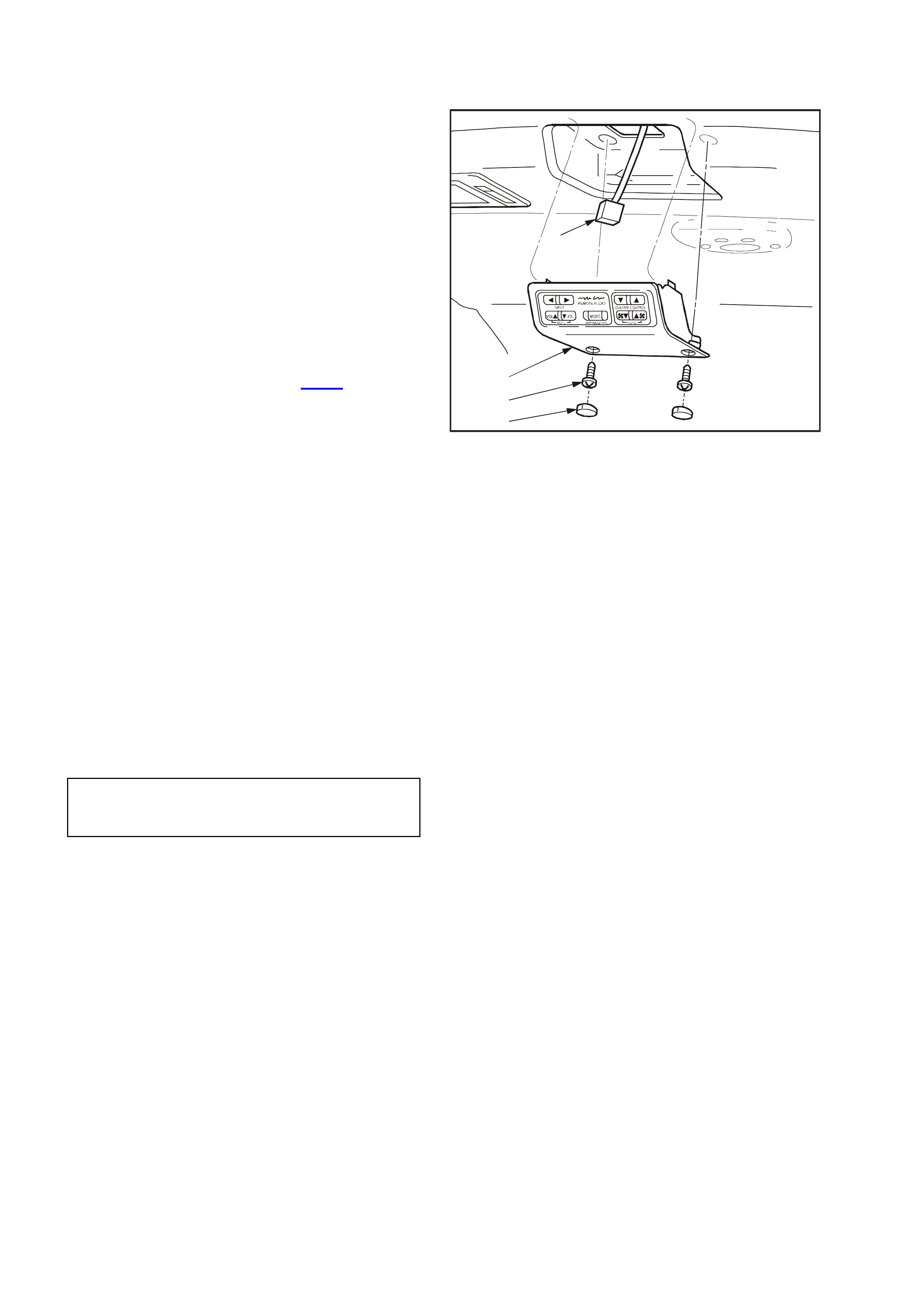
1. Remove two screw caps (1) f rom f orward edge
of remote control unit and remove two screws
(2) securing remote control unit (3) to roof
reinforcement.
2. Lower the forward edge of remote control unit
and push the unit forward to disengage rear
mounted support hooks from roof
reinforcement.
3. Disconnect wiring harness connector (4) from
top of remote control unit.
TEST
1. Connect an ohmmeter to the two terminals on
the side of the connector corresponding to the
audio controls (refer to Fig. 12D-7 for circuit
details). Press each button and check for the
following readings:
MODE 2 kohms
VOLUME UP 560 ohms, VOLUME DOWN
330 ohms
NEXT RIGHT 1 kohms, NEXT LEFT 100 ohms
2. Connect an ohmmeter to the two terminals on
the side of the connector corresponding to the
climate controls. Press each button and check
for the following readings:
FAN UP 560 ohms, FAN DOWN 330 ohms
TEMP UP 1 kohms, TEMP DOWN 100 ohms
WH12D026
2
3
4
1
Figure 12D-28
REMOTE CONTROL UNIT
RETAINING SCREW
TIGHTENING TORQUE 1 – 3 Nm
2.12 COMPACT DISC PLAYER/ CHANGER INSTALLATION
REMOVE
1. Open rear compartment and remove carpet,
refer to Section 1A1 BODY in this
Supplement.
2. Remove right side rear compartment
wheelhouse trim. Refer to Section 1A1 BODY
in this Supplement.
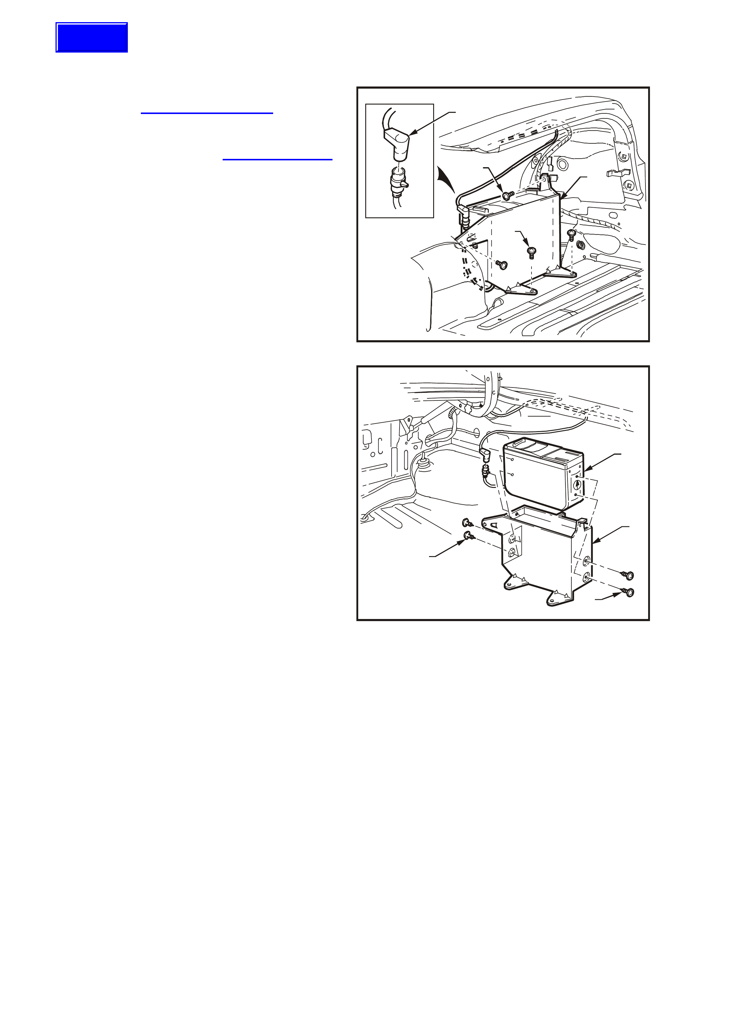
3. Disconnect CD changer harness connector (1)
refer to Fig 12D-29.
4. Remove four screws (2) securing CD changer
mounting bracket (3) to floor, inner guard and
rear panel of rear compartment and remove
CD changer mounting bracket (3).
WH12D014
1
2
2
3
Figure 12D-29
5. Remove four screws (1) securing CD changer
(2) to mounting bracket (3) and withdraw CD
changer (2) from mounting bracket (3). Refer to
Fig 12D-30.
REINSTALL
1. Installation is the reverse of the removal
procedure.
2. Check CD changer operation.
WH12D015
2
3
1
1
Figure 12D-30
Techline
2.13 SUBWOOFER AMPLIFIER
REMOVE
1. Open rear compartment and remove carpet,
refer to Section 1A1 BODY in this
Supplement.
2. Remove trim retainer from left side rear
compartment wheelhouse carpet trim and
rem ove left side rear com partment wheelhouse
trim, refer to Section 1A1 BODY in this
Supplement.
3. Loosen subwoofer amplifier retaining screws
(four screws) and s lide amplif ier (1) upwards to
release screw heads from inner side panel.
4. Disconnect subwoofer amplifier assembly
harness connector (2).
5. Withdraw subwoofer amplifier assembly (1)
from rear compartment.
WH12D016
21
Figure 12D-31
REINSTALL
1. Installation is the reverse of the removal
procedure.
2. Check subwoofer amplifier operation.

3. DIAGNOSIS
This radio problem diagnosis is split into several parts.
1. The first part is a short description of the principles of radio operation. It is by no means exhaustive, and is to
serve only to give an understanding of how radios work in order to better understand how to solve problems
when they occur.
2. Many radio problems are caused by basic earthing and short-circuiting problems, which can be quickly found
using the checks included in the ‘Basic Checks’ in this Diagnosis Section.
3. The m ost comm on fault is that of ‘static’ and so an explanation of what it is, what caus es it, and how to fix it is
also included.
4. Diagnostic flow charts are included to help diagnose common complaints.
PRINCIPLES OF OPERATION
Radio Reception
High quality r adio rec eption is obvious ly more dif ficult to achieve in a moving vehic le than f r om a s tationar y location.
Radio systems fitted to vehicles incorporate sophisticated electronics to enhance radio reception by extending the
useable listening range while eliminating extraneous noises, such as static.
Many owners complain of ‘reception problems’ which are normal radio operating characteristics, particularly with
FM. Such complaints arise as a result of owner misconception as to what constitutes normal radio reception.
Naturally, radio replacement under these circumstances will not affect the radio operating characteristics and has
the potential to create additional owner dissatisfaction. Thus a caref ul, well informed explanation of radio reception
expectations is more lik ely to enhance the owner’s understanding and s atisf action, as well as avoiding unnec essar y
repair costs and inconvenience to the owner of the vehicle.
FM Reception In Vehicles
FM stereo’s maximum range is normally limited to 40 to 50 km. The strength of the FM signal is related to the
distance between the receiver and the transmitter. FM signals follow the line of sight, exhibiting many similar
character istics to those of light. T hat is , similarly to sunlight, FM radio waves are cut of f by the hor izon. Since m ost
FM transmitter towers are nominally 100 metres from the ground, useable reception cannot extend much beyond
the horizon. FM signals will not bend around corners, but as with light, may be reflected (or blocked) by large
objects such as hills and buildings.
Figure 12D-32
Although FM signals will not bend around corners, they can be reflected by large structures, hills, or buildings, for
example. Because of these characteristics, a reflected signal and a direct signal can reach the radio’s antenna at
the same time, resulting in the signals interfering with each other or cancelling each other out. This obviously leads
to a distortion of the received signal or a loss of sound, and is known as multi-path interference.
Multi-path interference occurs only w ith FM reception and can be characterised by changes in distortion (static)
levels occurring as the vehicle is moving. This is due to the vehicles antenna entering and leaving FM signal
interference areas.
FM signal waves have short wavelength, which also means that the interference area is small - in the region of
several centimetres across. Because of the small size of interference areas, a vehicle may pass through many in a
short time. When the vehicle is stationary in an interference area, moving it half a metre will place the antenna in a
region of clear signal.
A vehicle fitted with a two antenna FM diversity system helps reduce multipath interference by ensuring that at least
one antenna is outside the cancelled signal region.
Flutter or fading is caused when a vehicle passes into an area where the direct signal can be overshadowed by a
building, large structure or hill.
Techline
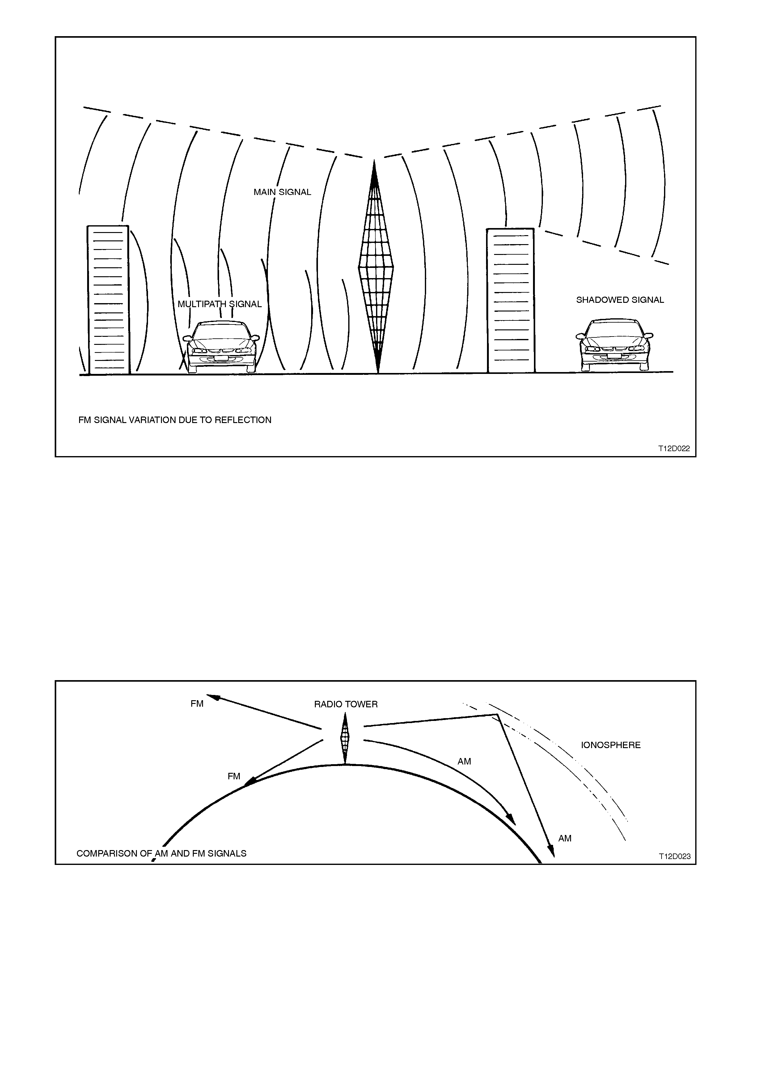
Figure 12D-33
Atmospheric conditions can also affect FM reception. Unexplained loss of sensitivity can be caused by high
humidity. Cloudy days are also better for reception than clear days. With electronic tuning radios, users can
sometimes be confused by abbreviated radio station call signs. People who tune their radio to these abbreviated
call signal frequencies may be slightly off the correct frequency.
NOTE: FM station call signs are spaced 100 kHz apart in Australia, ie. 93.9, 94.0, 94.1, etc.
AM station call signs are spaced 9 kHz apart, i.e. 999, 1008, 1017, etc.
AM Reception In Vehicles
In contrast to FM s ignals, AM signals will bend around co rner s and s kip along the ground. This is due to AM s ignals
having longer wavelength and lower frequency. The signal can be reflected by the layer of atmosphere known as
the ionosphere. This phenomenon gives AM a longer reception range than FM.
Figure 12D-34
AM reception is affected by static induced by electrical power lines, traffic lights, electronic signs and
thunderstorms. Fade of AM signals can also be expected when driving through tunnels, underpasses, and in city
centres.
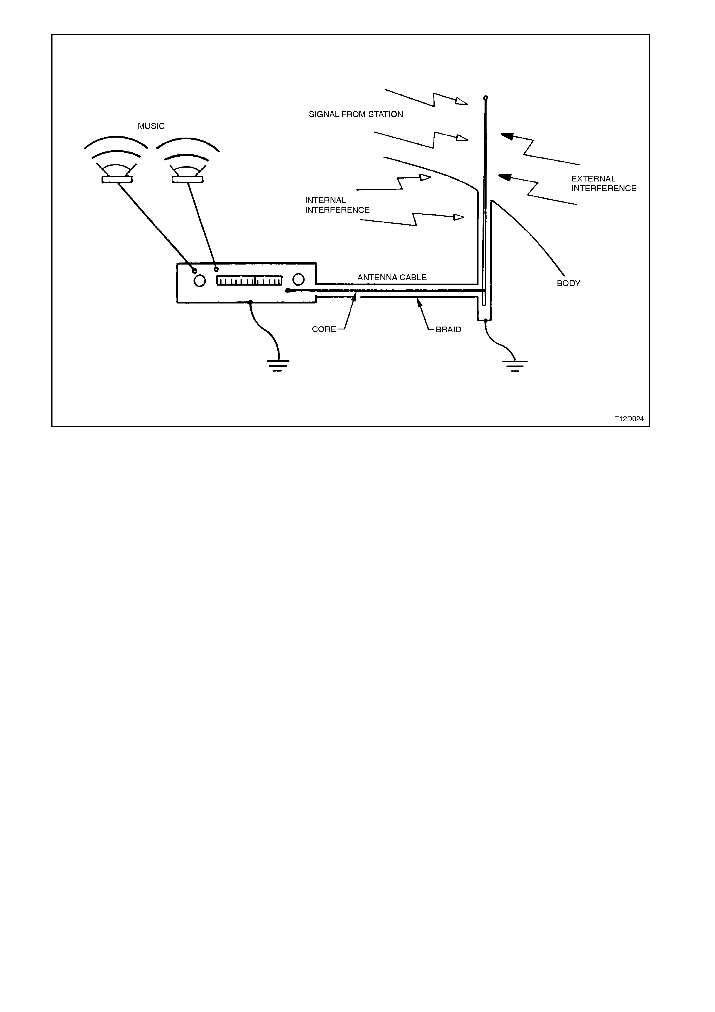
Figure 12D-35
As shown, signals from radio stations are picked up by the antenna and fed to the radio while being shielded from
interference sources by the braid. This is a complete electrical circuit, any breaks in the circuit, such as poor
connections, will result in poor reception.
Interference is due to the antenna system picking up signals other than those from the desired station. These
undesirable signals may be produced by electr ical equipment in the vehic le itself, such as ignition, which is termed
‘internal interference’. Conversely, interference from sources outside the vehicle, such as from power lines, is
known as ‘external interference’.
Internal interference is minimised by the shielding around the antenna wire, which prevents internal noise being
picked up and fed to the radio. The shielding around the core takes the form of a ‘braid’, which completes the
electrical circuit along which signals travel to the radio. Faults in this shielding system allow interference to reach the
radio and hence be reproduced at the speakers as noise.
It is therefore important that the shield of the antenna cable is effectively earthed at both the radio (to the radio
case) and at the antenna end (to the vehicle body ), to ensure that:
1. Minimal interference is received by the radio.
2. The optimum radio sensitivity is achieved.
BASIC CHECKS
Proper performance of the radio system depends greatly on earthing of the antenna and radio case to the vehicle
body, as it elim inates stray currents in the antenna circuit. Stray currents may be induced by wires running parallel
to the path of the radio or antenna wiring, or may be due to ‘noisy’ in-vehicle electrical items.
With an ohmmeter, the resistances or connection quality can be checked for the major parts of the radio.
When using an ohmmeter to measure very low resistances, the lead resistance becomes considerable, and must
be subtracted from all subsequent readings. That is, touch the leads together, note the reading, and subtract this
from all subsequent readings.
NOTE: A very good contact point is required to m easur e earth resistanc e. This point m ust not have c urrent f lowing
through it during measurement, therefore ensur ing that the ignition is turned O FF . Avoid measur ing us ing the s cr ew
on the door jamb switch. The best place to measure earth resistance is to use one of the self tapping screws
retaining the A-pillar drip rail. Since these screws are sometimes not properly earthed, one of the screws may be
removed to take measurements directly to the body sheet metal.
1. Remove battery earth lead.
NOTE: Failure to disconnec t batter y earth lead may
lead to incorrect resistance measurements due to
stray currents.
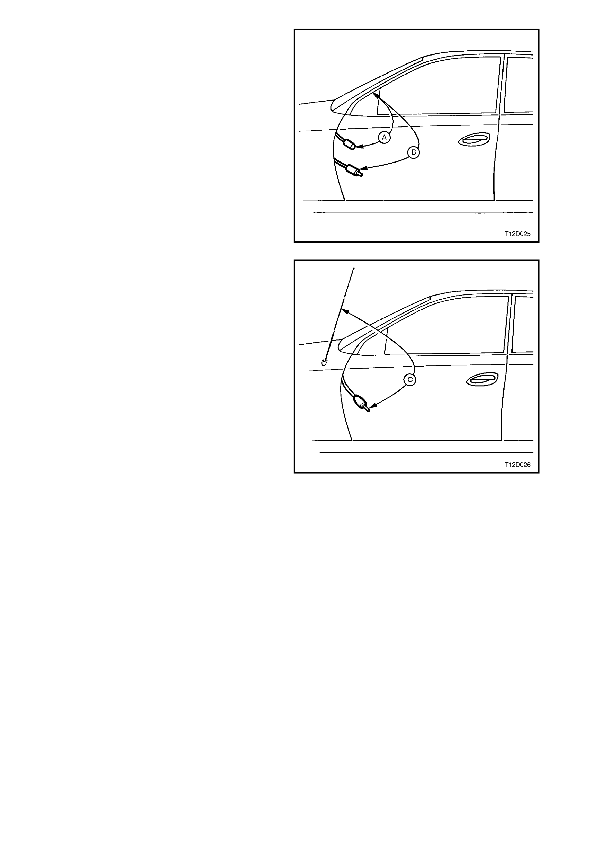
2. Disconnect antenna extension lead from
behind passenger side kick trim.
3. Measure resistance from the outer of the
antenna lead to vehicle body (A).
Resistance reading 0.3 ohm max.
4. Measure resistance from outer of the antenna
extension lead to vehicle body (B).
Resistance reading 0.6 ohm max.
Figure 12D-36
5. Check continuity of path from antenna cable
core to antenna mast by measuring resistance
(C).
Resistance reading 0.4 ohm max.
NOTE: This test can in fact only be performed on
power antennas, since manually operated antennas
are fitted with in-line capacitors with the antenna
body, which misleadingly indicates an open circuit
when resistance is measured.
On vehicles with manually operated antennas,
disconnect antenna lead from antenna lead
extension and measure resistance of extension
lead cable core from radio to antenna lead
connection ends.
Resistance values significantly higher than those
specif ied indicates poor c onnections which m u st be
rectified before proper radio performance will be
obtained.
6. Check for shorts between antenna core and
braid by disconnecting from radio and
meas ur ing the res istanc e between the two. The
meas ured value should indicate an open c ircuit
(very high or infinite resistance).
7. Disconnect antenna extension lead at both
ends and test core for continuity.
Figure 12D-37
COMMON RADIO PROBLEMSCOMMON RADIO PROBLEMS
Static
Static is a buzzing or crack ling noise caused by the radio pick ing up unwanted r adio waves and converting them to
noise output by the speakers.
The unwanted radio waves (interference) come from several sources, which can be put into two groups; internal
and external. As the names sugges t, ex ternal inter f er ence c omes from outside the vehicle, and is dif f icult to control,
while internal interference is generated by the vehicle.
It must be emphasised that a radio system in good condition will protect itself from much static. Before trying to
locate and rem ove a sourc e of interf erenc e it m ust f irst be deter m ined that the shielding and earthing of the radio is
in good working order. This can easily be done by performing the tests detailed in the ‘Basic Checks’.
It should be noted that static may occur on weak stations, or when driving under bridges because signals from
ignition and the like become relatively stronger than the radio station signal, causing the ignition interference to
become quite strong. This could be due to stronger than normal ignition interference or a poorly-functioning
antenna.
If the cause cannot be isolated after performing the tests and trying to isolate a source of interference, using the
following procedures, it may be that the radio has an internal fault and requires repair.
External Interference
Static which occurs only while travelling in certain localities, such as near electrical transformers, is undoubtedly
external interference.
If there is any doubt whether the suspected source is causing interference, a simple check is to stop the vehicle and
turn off everything but the radio. If the source is external, the interference will continue and little can be done to
eliminate it.
NOTE: The per c eived inter f erenc e level c an be s ignif icantly reduced, in noisy environments , by slightly reducing the
treble on the radio tone controls.
Internal Interference
Internal interference is that caused by some component of the vehicle’s electrical system, and may take many
forms.
Many of the electrical items fitted to motor vehicles produce som e sort of radio waves, but these radio waves only
become a problem if they are in the range of frequencies at which the radio receiver picks up and reproduces
signals as sound. For the radio, the vehicle’s electrical system must be designed not to emit radio signals at the
frequencies of the AM and FM bands.
Components are sometim es fitted with suppressing devic es as par t of their des ign, and f ailur e of thes e suppr es sor s
may allow the item to start interfering with radio operation.
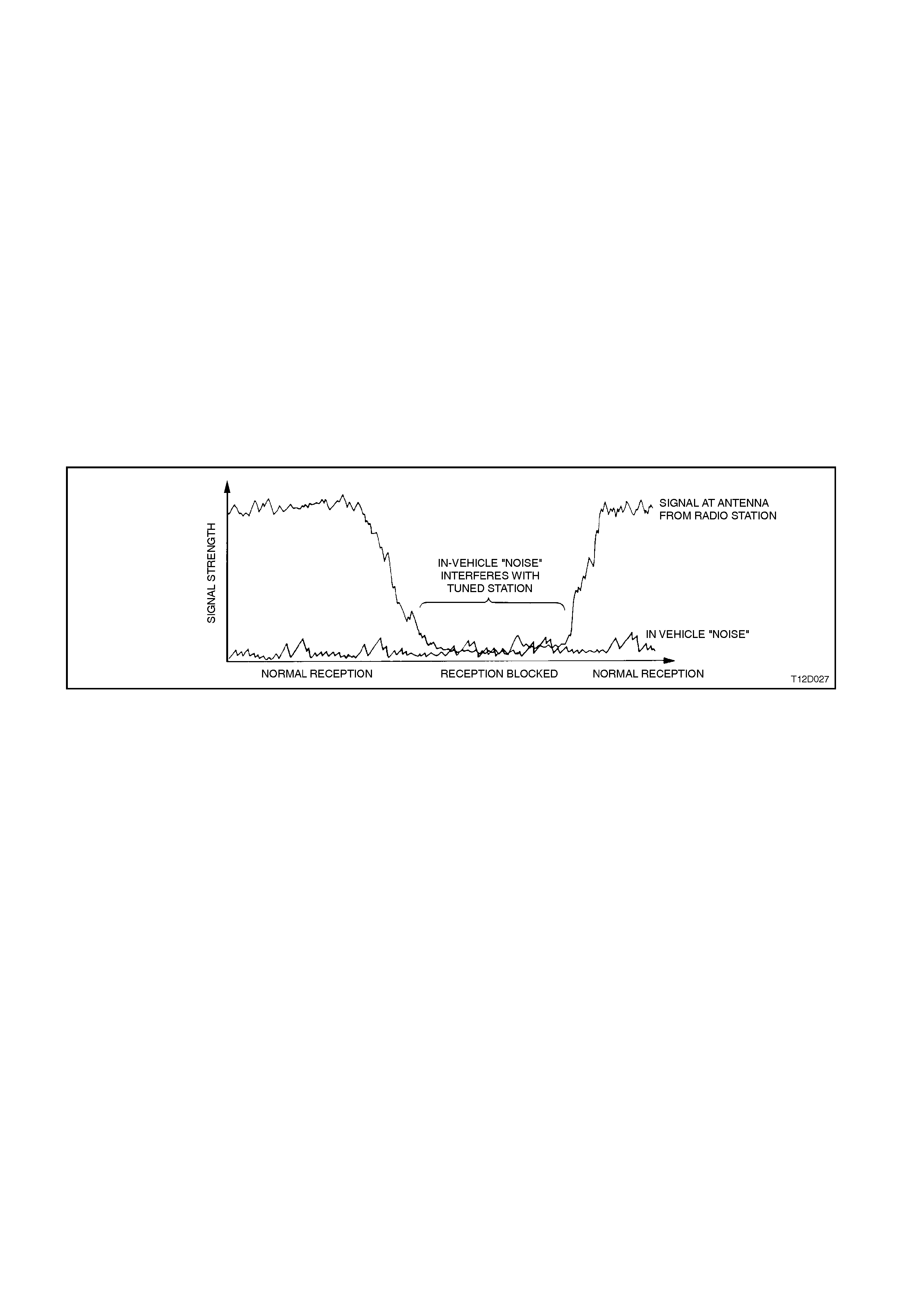
Interference will be worse on weak stations, since a strong signal normally overpowers the interfering signal.
Interference can occur when the signal strength drops below a certain threshold, such as driving under a bridge,
inside a workshop, or in the shadow of a building. This situation is shown in the following figure.
Figure 12D-38
Static may be caused by many internal sources. If static is at ignition frequency, varying with engine speed, the
ignition is the culprit. However, many electrical faults will cause static which otherwise would not be heard.
Examples of ignition interference sources are:
1. Plug leads breaking down.
2. Carbon tracking (arcing) to earth.
3. Faulty spark plugs.
4. Inoperative interference shields.
The actual cause of the interference can be isolated through carefully noting the circumstances under which the
problem occur s . For example, if it occ urs only at speeds above approximately 80 km /h in an automatic trans miss ion
equipped vehicle, quite possibly it is the electrical signal being sent to the torque converter clutch.
Other sources of static can be:
1. Electric cooling fan.
2. Electric fuel pump.
3. Normal computer ‘noise’ at certain frequencies.
4. Windshield wipers or washers.

Diagnosing Internal Interference
If a vehicle has an interference problem that only occurs when the engine is turned ON, or som e other repeatable
circumstance, carry out the following procedure:
1. Park vehicle in an open area, as far away from buildings as possible. Turn the radio onto the band (AM\FM) and
frequency where the complaint occurs, with the ignition on ACC.
2. Reproduce the interference, eg. turn ignition ON.
3. If interference is due to a fan blower motor, etc. and is judged to be objectionable, the component should be
substituted to determine whether it is faulty.
NOTE: Internal interference is often a symptom of a defective radio system, such as poor antenna earthing, etc. If
substituting a new c omponent does not f ix the c ondition, the pr oblem is ver y likely to be in the radio system, and the
resistance checks in this Section should be performed.
4. W histles /squeals that oc cur only when the ignition is ON, are pr obably due to electronic m odules in the vehicle
creating interference when active (power applied). These m odules may be isolated as a cause of interference
by removing power to them and rechecking. This is best done by turning the ignition OFF, removing the fuse
that supplies that particular item with power, turning the ignition back on and rechecking. By process of
elimination, the ‘noisy’ module should be able to be found. Once found, substitute the module to find out
whether the interference is normal.
Speakers
Before removing speakers suspected of being noisy or faulty, ensure that any distortion which may be present is not
due to any of the following:
1. Foreign matter such as sand lying on the speaker cone.
2. Cable ties or other such material resting on the back of the speaker cone.
3. Incorrectly fitted speaker mesh or loose trim around speaker assembly.
4. Distortion of speaker assembly caused by the angled insertion of the speaker retaining screws. Speaker
problems due to this may be rectified by loosening the screws and retightening, being careful not to distort the
speaker cone again.
CASSETTE PLAYER CARE
To ens ure proper and r eliable operation, the oxides used in tape m anuf acture m us t be cleaned fr om the heads and
capstan drive of the unit, at intervals of no more than 100 hours of operation. Sticky oxide build up on the capstan
can result in tape speed var iation, and ultimately in tape damage. Henc e it is important that user s are advis ed of the
importance of keeping cassette units clean.
Cassette players may be cleaned using a wet head cleaning tape.

3.1 DIAGNOSTIC PROCEDURES
When using the diagnostic charts, refer to the relevant circuit diagrams in Section 12P WIRING DIAGRAMS in this
Supplement.
RADIO/CASSETTE PLAYER FAULT DIAGNOSIS
The f ollowing chart sets out com m on user com plaints and s ymptom s with refer ence given to which diagnostic c hart
to follow for problem rectification.
Complaint Sym ptom Table No.
Power No power/illumination 1
Sound No sound/Low sound 1, 2
One speaker low/not working 1, 2
Distortion/Poor sound 1, 2, 3
Noise 1, 2, 3
Radio No or weak reception 3
Vehicle Interference 3
External Interference 3
Search tune skipping stations 3
Tape Tape speed too fast/slow 4
Noise 1, 2, 4
Jammed cassette mechanism 4
Will not eject tape 4
Can’t insert tapes 4
CD Player CD Changer error messages 5
Cannot select CD mode 5
CD player skips 5
CD player repeats same passage of sound 5
Horn Bar Stereo Controls No/unexpected operation 6
Roof Mounted Remote
Stereo Control – Caprice No operation 7
Power Antenna Fails to extend 8
Fails to retract 8

TABLE NO. 1: POWER AND SOUND DIAGNOSIS
STEP ACTION RESULT YES NO
1• Turn ignition switch to ACC position.
• Turn radio on.
• Does the display illuminate correctly?
Go to Step 5. Go to Step 2.
2• Partiall y remove radio, ref er to 2.1 RADIO/CASSE TTE
PLAYER in this Section.
• Is c onnector firmly pushed i nt o rear of radio?
Go to Step 3. P ush connect or firml y
into back of radio and
verify correct operation.
3• Using multimeter, check vol tage of circuit 43 (Yel l ow wire)
on radio connector YB72.
• Is t here at l east 11 volts on the ignit i on/accessory m ai n
radio connector?
Go to Step 4. Go to Step 16.
4• Using multimeter, check continuity of earth circuit 1151
(Black/Whit e wire) at connector Y B 72 using suitable body
earth location.
• Is there continuit y?
Remove and ret urn for
repair. Recti fy the earth
connect i on probl em
and verify repair.
5• Is there sound from al l speakers? Go to Step 6. Go to Step 2 of Tabl e
2.
6• Check t he terminal s at the rear of t he affect ed speakers.
For door speakers , check that they are in good condition
and do not cont act the body work. Look for signs t hat
contac t with the body work m ay have occurred previous l y.
• Tap door panels to verify that terminals will not make
contac t with body work, and insulate term i nal s if
necessary.
• Are there indications t hat the speak er terminal s have
made c ontact with t he body work?
Insulate terminals and
check speaker
operation. Go t o Step
14.
Go to Step 7.
7• Is t he sound distorted in all modes (radio, casset te, CD)? Go to Step 8. S ee rel evant diagnosti c
chart in this section.
8• Using multimeter, check vol tage of circuit 43 (Yel l ow wire)
on radio connector YB72.
• Is t here at l east 11 volts on the ignit i on/accessory m ai n
radio connector?
Go to Step 9. Rect i fy the voltage
connect i ons and verify
repair.
9• Is c onnector firmly pushed i nt o rear of radio? Go to Step 10. Push connector firmly
into back of radio and
verify correct operation.
10 • Use fader and balance controls to decide whether
distort i on i s from one or more speakers.
• Is distortion from one s peaker only?
Go to Step 11. Remove and ret urn f or
repair.
11 • Is there foreign matter suc h as dirt in t he speaker cone? Clear the speaker of
foreign matter and
verify repair.
Go to Step 12.
12 • Ensure s peaker term i nal s do not touc h body work.
• Is t he connector f i rmly on the s peaker?
Go to Step 13. Push connector firmly
onto speak er and veri fy
repair.
13 • Check t hat the correc t speaker has been fitted t o the
vehicle. The appropri ate type must be fit ted for correc t
operation, ref er to:
2.2 FRONT INSTRUMENT PANEL SPEAKERS - ALL
MODELS,
2.3 FRONT DOOR SPEAKERS - ALL MODELS,
2.4 REAR DOOR SPEAKERS,
2.5 SUBWOOFER SPEAKERS, and
2.6 ROOF MOUNTED SPEAKERS - CAPRICE in this
Section.
• Is t he correct s peaker instal l ed?
Go to Step 14. Fi t correct s peaker and
verify repair.

TABLE NO. 1: POWER AND SOUND DIAGNOSIS (CONTINUED)
STEP ACTION RESULT YES NO
14 • Connect a working s ubstitute speaker.
• Does the s peaker work clearly?
Inst al l new speak er,
ensuring correct
impedance and verify
repair.
Go to Step 15.
15 • Is the wiring t o the speaker damaged? Repair fault i n harness. Remove and ret urn for
repair.
16 • Check fuse F16.
• Is fuse OK?
Go to Step 17. Replace fuse and
investi gate cause of
blown fuse.
17 • Check c ontinuity of wiring harnes s from i gni tion switch
connect or Y B44 to fus e F16 (circuit 4, Brown wire), and
from fuse F16 to radio harness connector YB72 (circuit
43 , Yellow wi re).
• Is there continuit y?
Invest i gate source of
voltage int erruption
from i gni tion switch and
battery.
Repair wiring harness
and verify repair.

TABLE NO. 2: INTERMITTENT FAULT DIAGNOSIS
STEP ACTION RESULT YES NO
1• Does cus tomer c omplain of sound dropping out during all
modes i ntermittently? Caprice Go to S tep 2.
Statesman go t o S tep
4
See relevant diagnostic
table in thi s Sect i on.
2• Caprice only – ens ure that headphones are removed,
then press the headphone button on the radi o to override
the headphone circuit.
• Does radio display NO REAR HE ADPHONES?
Go to Step 3. Remove and ret urn
radio for repair.
3• Caprice only – install headphones, then pres s the
headphone button on the radi o.
• Does radio dis p l ay HE ADPHONES ON?
Go to Step 4. Remove and ret urn
radio for repair.
4• Does the drop-out occur only in one or t wo speakers? Go to Step 5. Go to Step 6.
5• Check c onnections at the relevant speaker and harness
connect ors between speaker assembly and radi o. Inspec t
term i nal s for dam age or poor f it.
• Check that headphones are not still plugged in (Caprice
only).
• Check t he terminal s at the rear of t he affect ed speakers.
For door speakers , check that they are in good condition
and do not cont act the body work. Look for signs t hat
contac t with the body work m ay have occurred previous l y.
• Tap door panels to verify that terminals will not make
contac t with body work, and insulate term i nal s if
necessary.
• Do the connec t i ons appear OK, even when pulled and
manipulated?
Go to Step 10 of
Table 1. Repair harness or
replace speaker if
term i nal s are
damaged, and veri f y
correct operation.
6• Check c onnections at rear of radio, i nspect t erminals for
damage or poor f i t .
• Do the connec t i ons appear OK, even when pulled and
manipulated?
Go to Step 7. Repair harness and
verify correct operation.
7• Using multimeter, check f o r continuit y of cellular
telephone mute circuit 656 (Yel l ow/Bl ack wire) on radio
connect or YB72 to body earth.
• Does this circui t indicat e continuity to earth?
Cellular tel ephone
mut e l i ne has shorted
to earth, locate short
circui t and/or dam age
to harness and veri fy
repair.
Go to Step 8.
8• Does cus tomer c omplain of sett i ngs (ie, volume, mode,
radio stat i on, bass/ treble etc) changing when ignition is
turned from ACC to ON when starting the car?
Refer to Note 1 at the
end of this Tabl e. Go t o S tep 9.
9• Does cus tomer c omplain of sett i ngs (ie, volume, mode,
radio stat i on, bass/ treble, antenna hei ght etc) changing,
or intermittent erratic audio system operation when driving
the car.
Refer to Note 2 at the
end of this Tabl e. Remove radio and
return for repair.
Note 1
Inform customer that the priority key settings are restored from the BCM when the vehicle is unlocked with the
remote using its priority key signal. These settings will be restored when the ignition is turned to ACC position. The
BCM will request the priority key settings of the key in the ignition when the ignition is cycled. If a different key is
then used to start the car, or the car was not locked and a different key used to start the car the BCM will use the
priority key settings for the current key. This may result in the settings changing when the ignition is cycled, and is
part of normal operation.
Suggest to customer that the key used to start the car should be the same key used to unlock the car.
Note 2
If there is an intermittent open circuit or short circuit to body earth in the priority key circuit (Grey) from the BCM to
the radio then the priority key settings may alternate. As the priority key changes, the radio settings will change to
reflect the values stored in each key. This will result in volume, mode, radio station, bass/treble settings to change
for apparently no reason.
This can additionally cause the radio to switch on and off erratically if one priority key sets the radio on and the other
turns it off.
The priority line circuit will need to be investigated for a short or open circuit, refer to Section 12P WIRING
DIAGRAMS in this Supplement.

TABLE NO. 3: RADIO/RECEPTION DIAGNOSIS
STEP ACTION RESULT YES NO
1• When radio m ode i s selec t ed, is there no reception or
weak reception? Go to Step 2. Go to Step 7.
2• Fully extend antenna and move vehi cle to k nown high
quality rec eption area.
• Is reception st ill weak?
Go to Step 3. Confirm probl em with
customer.
3• Is the antenna plugged into t he rear of the unit and behind
the pass enger’ s side ki ck trim? Go to Step 4. Plug t he ant enna i nto
the unit and behind
passenger’s side k i ck
trim. Go back to
Step 1.
4• Compare t he weak s i gnal i n this vehic l e with that coming
from a vehi cle which does not experience t hi s problem .
• Does the weak si gnal sound more evi dent i n this vehicle
than the comparis on car?
Go to Step 5. E xplain t o t he customer
that the weak s i gnal or
distort i on appears to be
one affec t ed by the
locati on of the car.
Refer to Principles of
Operation in
3 DIAGNOSIS in this
Section.
5• Has a new antenna been attac hed to the back of the
radio? Remove and return unit
for repair. Go to Step 6.
6• Attach a new lead and retest.
• Is reception st ill weak?
Remove and ret urn uni t
for repair. Fit new antenna and
verify repair.
7• Is t here vehi cle related interference, t hat is, i t disappears
when vehicle’s electrical system and engine are off ? Go to Step 8. Go to Step 10.
8• Can the caus e be l ocated by turning off various vehicle
components? Go to S tep 9. Remove and ret urn f or
repair.
9• Is the noi se a whine, such as from t he vehi cle’s al ternator
or with increase i n engi ne speed? Undertake t he
necess ary steps to
ensure that the
generator/coil
suppress or and earth
to radio function are all
fully operational . Go
back t o S tep 7
Go to Step 10.
10 • Has a new antenna extension lead been ins talled? Go to Step 11. Attach a new antenna
extension lead, rout ed
away from the ot her
wiring. Go back t o
Step 7.
11 • Using a multimeter, check t he resist ance from the radio
case t o the body earth at instrum ent carrier (refe r t o
Sect i on 12P WIRING DI AGRAMS in thi s Supplement.
• Is the resist ance greater than 0.5 ohms?
Remove and ret urn for
repair. Remove and return for
repair.
12 • Is t here external interference, that appears only in certain
locations? Advis e the customer
that external
interferenc e cannot be
elim i nat ed unl ess the
source is elim i nated.
To reduce this
interference, extend
antenna fully and i f the
interference is a high
frequency noise, use
the treble c ontrol to
reduce treble
response.
Go to Step 13.
13 • Does the s earch tune sk i p stations? Go to Step 14. Conf i rm problem with
customer.
14 • Fully extend the antenna.
• Switch off ‘LOC’ feature.
• Does the search tune still skip st ations?
Go to Step 15. Conf i rm problem with
customer.
15 • Test the antenna or extension lead for f aul t.
• Is antenna or l ead faulty?
Repair or replace t he
faulty component. Go
back t o S tep 13.
Remove and ret urn for
repair.

TABLE NO. 4: CASSETTE PLAYER DIAGNOSIS
STEP ACTION RESULT YES NO
1• Can cass ettes be inserted? Go to Step 8. Go to Step 2.
2• Is t he casset te mechanism empt y? Go to Step 6. Go to Step 3.
3• Attempt t o ej ect the c assett e by pressing the ej ect button.
• Did the cassett e ej ect easil y?
Go back t o S tep 1. Go to Step 4.
4• If the casset te ejected slightly, push it back into the uni t,
then exert normal pressure (not f orce) on eject but ton
while guiding the cassett e upwards.
• Did the cassett e ej ect?
Go to Step 5. Remove and ret urn
radio for repair.
5• Is the cassette door bent or damaged so that door i s
blocki ng casset te entrance? Remove and return
radio for repair. Go back t o S tep 1.
6• Does there appear to be a f orei gn obj ect within the
mechanism? Go to Step 7. Remove and return
radio for repair.
7• Is it possibl e to remove t he foreign object without
damaging t he uni t? Remove f orei gn obj ect
and go back t o S tep 1 Remove and return
radio for repair.
8• Does the t ape pl ay as though it i s in fast-forward mode? Remove and return
radio for repair. Go to Step 9.
9• Does the unit operate properly in all f unctions other than
cass ette m ode? Go to Step 12. Go to Step 10.
10 • Is t he t onal qual i ty poor which makes the out put sound
muffled? Clean the tape path
using only a wet
cleaning s ys tem. Go t o
Step 12.
Go to Step 11.
11 • Does the c assett e run slowly or switch to auto-reverse
before the end of the tape has been reac hed? Run the offendi ng
cassette on fast-
forward and fast-rewind
for full l ength and
check tape funct i on
again. Go to S t ep 12
Confirm problem with
customer.
12 • Insert a t ape which you know works without a problem .
• Does the unit work without a problem ?
End of diagnos tic
procedure. Rem ove and return
radio for repair.

TABLE NO. 5: CD PLAYER DIAGNOSIS
STEP ACTION RESULT YES NO
1• When attempting to use CD changer, does an error
mes sage appear? Go to Step 2. Go to Step 8.
2• Statesman onl y – I s it the error ‘ E01’ (No magazi ne in
disc changer)?
or
• Caprice only – I s it the mess age NO MAGA ZINE?
Insert a l oaded di sc
magazine i nto the
changer.
Go to Step 3.
3• Statesman onl y – I s it the error ‘ E02’ (No disc in the
magazine)?
or
• Caprice only – I s it the message NO DISCS?
Insert a disc into the
magazine. Go to Step 4.
4• Statesman onl y – Is it the error ‘E04’ (Disc is di rty or
upside down)?
or
• Caprice only – I s it t he mess age CHECK DISC?
Go to Step 5. Go to Step 6.
5• Check t hat the disc is cl ean and free from scratc hes and
inserted the correct way up.
• Is CD c l ean and i nserted properly?
Remove and ret urn for
repair. Recti fy problem and
verify repair.
6• Statesman onl y – I s the error ‘E08’ (CD changer is too
hot)?
or
• Caprice only – I s it the message CD CHANGER TOO
HOT?
• As with all compact disc players, the unit will not operate
if the ambient t emperature is above 55°C, otherwise
permanent l aser damage c an occur.
Remove and ret urn for
repair. Go to St ep 7.
7• Statesman onl y – I s the error ‘E99’ (Micro computer is
locked)?
or
• Caprice only – I s it the message ERROR 99?
Eject CD cartridge,
remove all discs and
insert empty cartridge
into CD changer. Hold
Off button on radio for
more t han 6 seconds,
then reload discs.
Remove and ret urn for
repair.
8• Can the CD m ode be selected and activated on the head
unit? Go to S t ep 10. Go to S tep 9.
9• Check t he CD connector on t he CD changer and in the
passenger c ompartment.
• Is t he CD connector s ecure and the harness undamaged?
Remove and ret urn for
repair. Reconnect or repair
harness and verify
correct operat i on. Go
back t o S tep 8.
10 • Does the CD c hanger skip on rough roads ? Go to Step 11. Go to Step 13.
11 • Are the spri ng adj uster caps on each end of t he CD
changer adjusted with the slot facing up-down? Go to Step 12. Adjust the spring
adjuster appropri ately
and verify repair.
12 • Road test t he vehicle.
• Does sk i ppi ng only occur under s evere conditions?
Explain to the c ustom er
that CD s kipping is
usually due t o di rt y or
scrat ched CDs. The
CD player does at
times skip on very
rough roads or if a
large pothole is
encountered.
Go to Step 14.
13 • Does the CD s kip or repeat the same pas sage of output ? Go to Step 14. Conf i rm problem with
customer.
14 • Insert and at tempt to play a known clean and properly
playing CD.
• Does the CD player continue to skip under normal driving
conditions?
Remove and ret urn for
repair. Explain to the customer
that CD s kipping is
usually due t o di rt y or
scrat ched CDs. The
CD player does at
times skip on very
rough roads or if a
large pothole is
encountered.
Techline

TABLE NO. 6: HORN BAR STEREO CONTROL FAULT DIAGNOSIS
STEP ACTION RESULT YES NO
1• Switch radio ON with key in ACC pos i tion.
• Do all switc hes operate correc tly?
Confirm problem with
customer. Go t o S tep 2.
2• Using multimeter, check resistance across radio
connect or YB73 circuit 515 (Brown wire) and circui t 701
(Black/Yellow wire).
• Does resistance indi cate open ci rcuit with no horn bar
buttons pressed?
Go to Step 3. Replac e switch
assemblies and veri fy
repair.
3• Using multimeter, check continuit y of circuit 515 (Brown
wire) and circuit 701 (Black/Yellow wire) between horn bar
radio control s connect or YB148 and radio connector
YB73.
• Is there continuit y of each of the c i rcuits ?
Go to Step 4. Repair harness and
verify repair.
4• Using multimeter, check t he resist ance of the circuit when
each of the buttons are pres sed.
• Press MODE switch on left-hand side of steering wheel.
Is resistance
between 20k6
and 22k8?
Go to Step 5. Replac e switch
assemblies and veri fy
repair.
5• Press NEXT ▲ switch on the left-hand side of steering
wheel. Is resistance
between 11k1
and 12k3?
Go to Step 6. Replac e switch
assemblies and veri fy
repair.
6• Press NEXT ▼ switch on the left-hand side of steering
wheel. Is resistance
between 6k7
and 7k4?
Go to Step 7. Replac e switch
assemblies and veri fy
repair.
7• Press MUTE switch on the right -hand side of steering
wheel. Is resistance
between 3k5
and 3k9?
Go to Step 8. Replac e switch
assemblies and veri fy
repair.
8• Press VOL ▲ switch on the right-hand si de of steering
wheel. Is resistance
between 1k4
and 1k6?
Go to Step 9. Replac e switch
assemblies and veri fy
repair.
9• Press VOL ▼ switch on the right-hand si de of steering
wheel. Does
multimeter
indicate
continuity?
Remove and ret urn for
repair. Replace s witch
assemblies and veri fy
repair.

TABLE NO. 7: ROOF MOUNTED REMOTE STEREO CONTROL FAULT DIAGNOSIS — CAPRICE
STEP ACTION RESULT YES NO
1• Switch radio ON.
• Do all rear rem ote control switches operate correct l y?
Confirm problem with
customer. Go t o S tep 2.
2• Remove t he rear remote c ont rol uni t, refer t o 2.11 ROOF
MOUNTED REMOTE CONT ROL UNIT — CAP RICE
• Test the rear remote c ontrol unit, ref er to 2.11 ROOF
MOUNTED REMOTE CONT ROL UNIT — CAP RICE
• Did rear remote control uni t test OK ?
Go to Step 3 Replace the rear
remot e control unit .
3• Disconnect connec tor YB73 from the radio.
• Using an ohmmet er, check continuit y of circuit 315 (White
wire) and circuit 701 (Black/Yellow wire) between radio
connect or Y B73 and rear remot e control unit connector
YB59.
• Is there continuit y of each circ ui t?
Remove radio and
return for repair. Repair c i rcuits as
necessary.

TABLE NO. 8: POWER ANTENNA FAULT DIAGNOSIS
The WH Statesman and WH Caprice are fitted with a high series BCM. For diagnosis, refer to Section 12J-2 HIGH
SERIES BODY CONTROL MODULE in this Supplement.
STEP ACTION RESULT YES NO
1• Does power antenna fail to operat e correctl y? Go to Step 2. Confirm problem with
customer.
2• Using multimeter check continuity of circuits 143
(Yellow/Red wire), 160 (White wire) and 161 (Light Blue
wire) between radio connector YB72 and BCM connector
YB175.
Is there continuit y?
Go to Step 3. Faulty c onnection from
radio/cassett e t o body
control module. Repai r
harness and verify
repair.
3• Using multimeter check continuity of circuits 145 (Green
wire) and 954 (Grey wire) between BCM connector YB 173
and power antenna connector Y B15.
Go to Step 4. Faulty c onnection from
body control module to
antenna m odule.
Repair harness and
verify repair.
4• Using multimeter check continuity of circuits 145 (Red
wire) and 954 (White wire) between power antenna
connector YB15 and the power antenna module
connector.
Go to Step 5. Faulty c onnection from
power antenna harness
connect or t o power
antenna m odule.
Repair harness and
verify repair.
5• Is forked earth lead c onnector securel y attac hed to power
antenna m odul e. Go to Step 6. Attach forked earth
lead connector to
power antenna module
and verify repair.
6• Replace power antenna module with a known working
one. Does ant enna work c orrectly? End of diagnos tic
procedure. Rem ove and return for
repair.
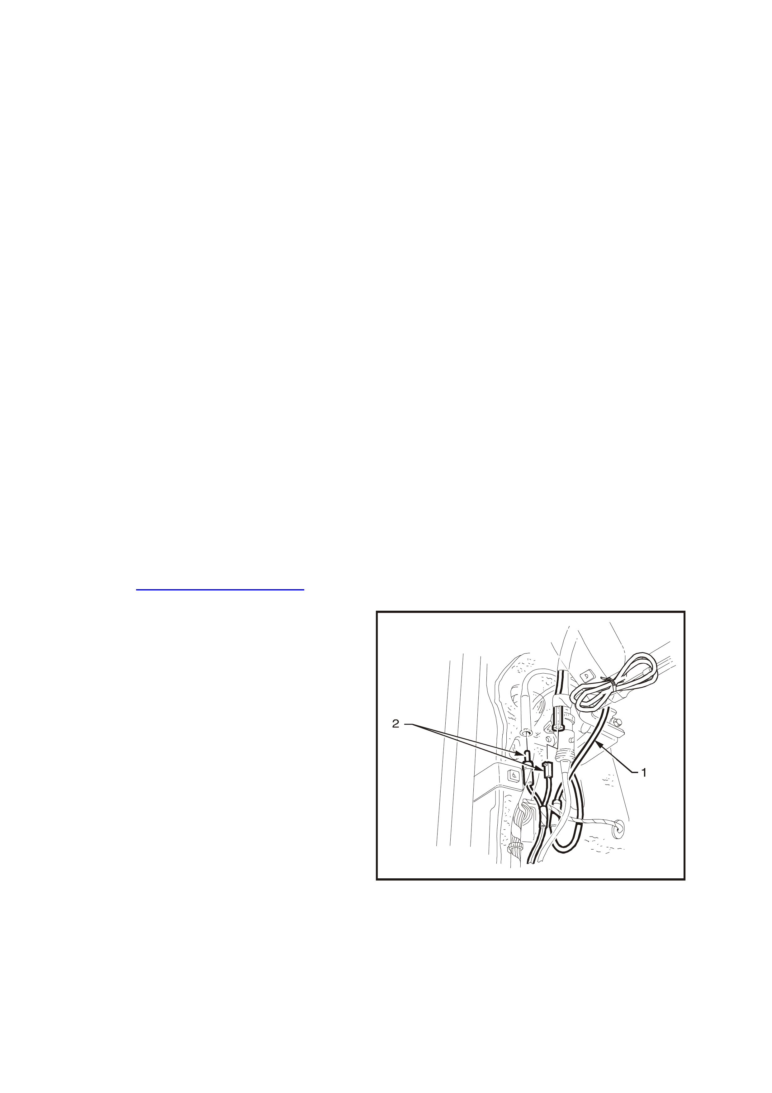
DIVERSITY ANTENNA FAULT DIAGNOSIS
Before commencing the diagnostic procedure for
the diversity antenna system the following should
be checked:
1. Determine whether the reception problem is
apparent with FM, AM or both.
Faults affecting both FM and AM reception are
not caused by the diversity antenna system
due to the fact that the diversity antenna
system only affects FM reception.
Such faults are m ore likely to be caused by the
conventional fender mounted mast type
antenna system.
2. Ensure that the customer complaint is not due
to normal operation or the limitations of FM
transmissions.
The diversity antenna system is designed to
minimise distortion in the sound quality of FM
reception and not to give large incr eases in F M
reception range.
Compare reception quality with that of another
vehicle equipped with a diversity antenna
system in the same location and under the
same conditions.
DIVERSITY ANTENNA SYSTEM TEST PROCEDURE
NOTE: W hen the vehicles conventional antenna is
lowered, disconnected or faulty, the radio will not
use the diversity antenna system to receive FM
radio signals. If no FM stations can be received
then the fault is not due to the diversity antenna
system.
1. Remove passenger side cowl panel cover.
Refer to Section 1A1 UNDERBODY in this
Supplement.
Locate the two antenna connectors near the
PCM. The thinner of the two connectors is the
diversity antenna system connector. The one
larger in diam eter is for the conventional fender
mounted mast type antenna.
2. Raise mast antenna to full height.
3. Switch the ignition key to the ACC position.
Switch the radio to the FM band and tune to a
weak station.
NOTE: A weak station can be selec ted by tuning to
different stations and picking one that is of a lower
intensity or contains more ‘noise’ than the others.
4. Lower mast type antenna. Radio reception of
the weak station should now be small enough
so that music can no longer be heard or is
extremely faint.
5. If music can still be heard strongly then repeat
Steps 3 and 4 with weaker stations until music
is virtually non-existent with the mast antenna
lowered.
6. Unplug diversity antenna system connector (2)
from extension to radio.
Unplug mast type antenna (1) from extension
to radio.
WH12D023
Figure 12D-39
7. Plug male diversity antenna lead into female
front antenna extension to radio, making sure
that the pin of the male connector is inserted
fully into the cavity in the fem ale connector and
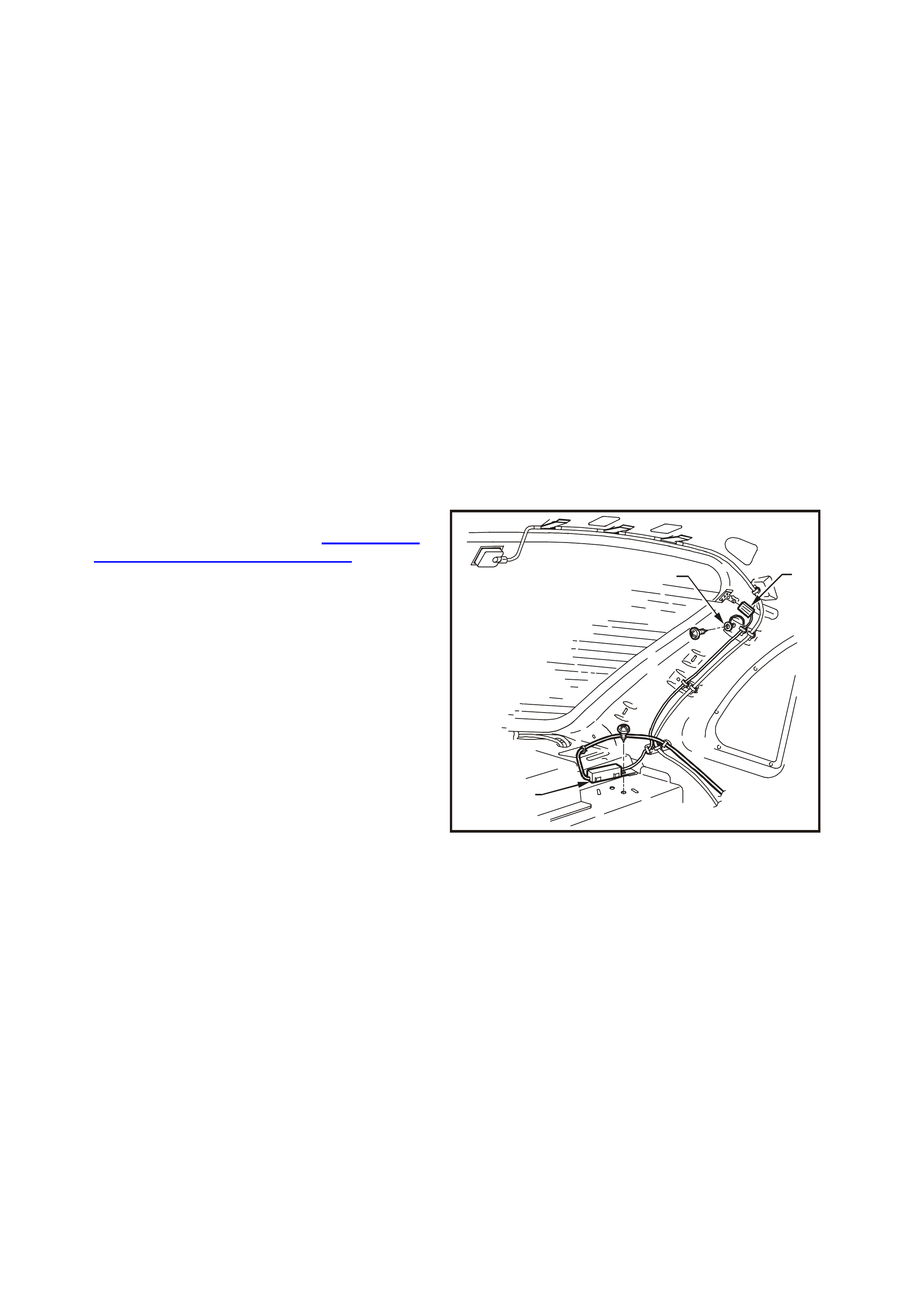
that the outer conductor of the diversity lead
connector is in contact with shielding of the
radio extension connector.
The diversity antenna system is now connected
to the radio’s conventional antenna input.
8. The radio should now receive the station with
only a little les s s tr ength than the mast antenna
did originally.
If the station cannot be heard, the diversity
antenna may be located in a FM signal
interference area.
To determine if this is the case move the
vehicle a few meters to see if stations
reception improves.
9. If station can be heard clearly then diversity
antenna system is operating correctly.
If the station still can not be heard then the fault
may be in diversity antenna system. Continue
with next step.
10. Test voltage at diversity antenna module to
main wiring harnes s connec tor with k ey in ACC
position. If 12 V then continue with next step.
If 0 V then trace wire back to fault and repair.
11. Remove passenger side quarter window trim
and parcel shelf. Refer to Section 1A8
HEADLINING AND REAR TRIM in this
Supplement.
12. Check connection from diversity antenna
module (1) to rear window connector (2).
Check earth terminal (3) for a good electrical
earth.
WH12D024
2
1
3
Figure 12D-40
13. Disconnect battery earth terminal. Measur e the
resistance from the case of the diversity
antenna module to a good earth point. If
greater than 1 Ω tighten module to parcel shelf
retaining screw and check resistance again.
14. Check diversity antenna f or continuity. Ref er to
DIVERSITY ANTENNA — TEST in this
Section. If antenna continuity is acceptable
then a new diversity antenna m odule should be
tried.

4. SPECIFICATIONS
STATESMAN AND CAPRICE
Radio/Cassette Player............................................. AM/FM Stereo/Cassette/CD Changer
Power Output .......................................................... Head unit – 4 X 30 watt
Subwoofer amplifier 2 X 70 watt max
Speakers
Type
- Instrument Panel.............................................. 2 speakers – instrument facia mounted tweeters
- Front Door........................................................ 2 speakers – front door trim mounted 150 mm full
range dual cone
- Rear Door ........................................................ 2 speakers – rear door trim mounted 150 mm full
range coaxial
- Rear Roof (Caprice only)................................. 2 speakers – rear roof mounted mid tweeters
- Rear Parcel Shelf............................................. 2 speakers – rear parcel shelf mounted 200mm
subwoofer
Impedance ......................................................... All speakers (except rear roof – Caprice) – 2 ohm
......................................................................... Rear roof speakers (Caprice) – 6 ohm

5. TORQUE WRENCH SPECIFI CATIONS
Nm
Power Antenna Module Attaching Screws............................ 1 – 3
Centre Facia Attaching Screws............................................. 1 – 3
Front Speaker Attaching Screws (all models)....................... 1 – 2
Front Door Speaker Attaching Screws (all models).............. 1 – 3
Rear Door Speaker Attaching Screws (all models) .............. 1 – 3
Demist Grille to Instrument Panel Attaching Screw.............. 1 – 3
Antenna Bracket to Inner Fender Panel Attaching Bolt ........ 3 – 6
Manual Antenna Bracket Screw............................................ 2 – 5
Diversity Antenna Module to Parcel Shelf Attaching Screw.. 1 – 3
Subwoofer Amplifier Attaching Screws................................. 0.5 – 1.5
Roof Mounted Speaker Attaching Screws............................ 1 – 3
Roof Mounted Remote Control Unit Attaching Screws......... 1 – 3
CD Changer Attaching Screws............................................. 1 – 3
Stereo Switch to Steering Wheel Attaching Screw............... 1 – 3
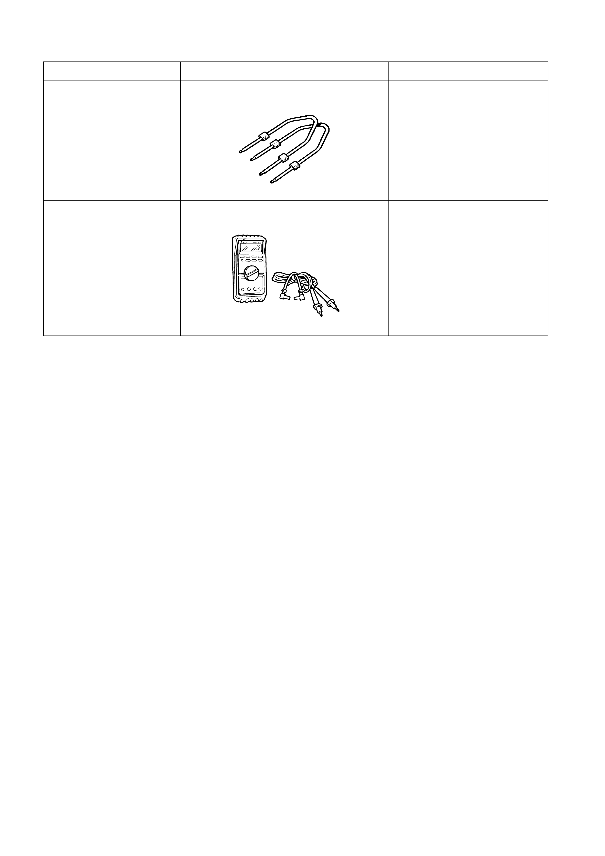
6. SPECIAL TOOLS
TOOL NO. REFIN TEXT TOOL DESCRIPTION COMMENTS
179 1308 0000 RADIO REMOVAL TOOLS
J39200 DIGITAL MULTIMETER TOOL NO. J39200 previously
released, or use commercially
available equivalent. Must have
10 megaohm Ohm input
impedance