
SECTION 12E - CRUISE CONTROL
IMPORTANT:
Before performing any Service Operation or other procedure described in this Section, refer to
Section 00 CAUTIONS AND NOTES for correct workshop practices with regard to safety and/or
property damage.
1. GENERAL INFORM ATION
Cruise control is a vehicle speed control system which maintains a desired vehicle speed without the driver having
to continually apply foot pressure to the accelerator pedal.
Cruise control is standard equipment on all WH Series models and is the same as that fitted to VT Series models. It
is an Electro-motor system that is vacuum independent. The Electro-motor cruise control system uses a stepper
motor to control vehicle speed.
On models fitted with GEN III V8 engines, a throttle relaxer servo is also fitted as part of the traction control system
to provide engine torque control. The throttle relaxer momentarily reduces the throttle opening angle when traction
loss occurs.
There is no electronic interface between the throttle relaxer and the cruise control module.
Techline
1.1 SYSTEM OPERATION
The main components of the Electro-motor cruise control system are the cruise control module, cruise control
switches (mounted on the turn signal stalk), brake pedal electrical release switch, brake pedal stop lamp switch,
cruise control cable and electrical wiring (incorporated into the main wiring harness).
The cruise control module also uses an output from the Powertrain Control Module (PCM) for vehicle speed, and an
input to the Body Control Module (BCM) to send a serial data message to the instruments (cruise control interface).
When the cruise control module is powered up via the cruise control ON-OFF switch, the cruise control module
activates an input to the BCM. The BCM sees this line as active and s ends a ser ial data mess age to the
instrument cluster to turn its CRUISE lamp on.
When the SET-COAST switch is depressed (provided the vehicle speed is above 40 km/h and the brake pedal is
not depressed) the cruise control module lights up the ACTIVE lamp in the instrument cluster and in turn, informs
the PCM to use a specific transmission shift pattern.
This is designed primarily for cruise mode, having fewer transmission down shifts and reduced transmission gear
change activity. For further information about the BCM cruise control interface, refer to Section 12J-2 HIGH
SERIES BCM of the VT Series II Service Information.
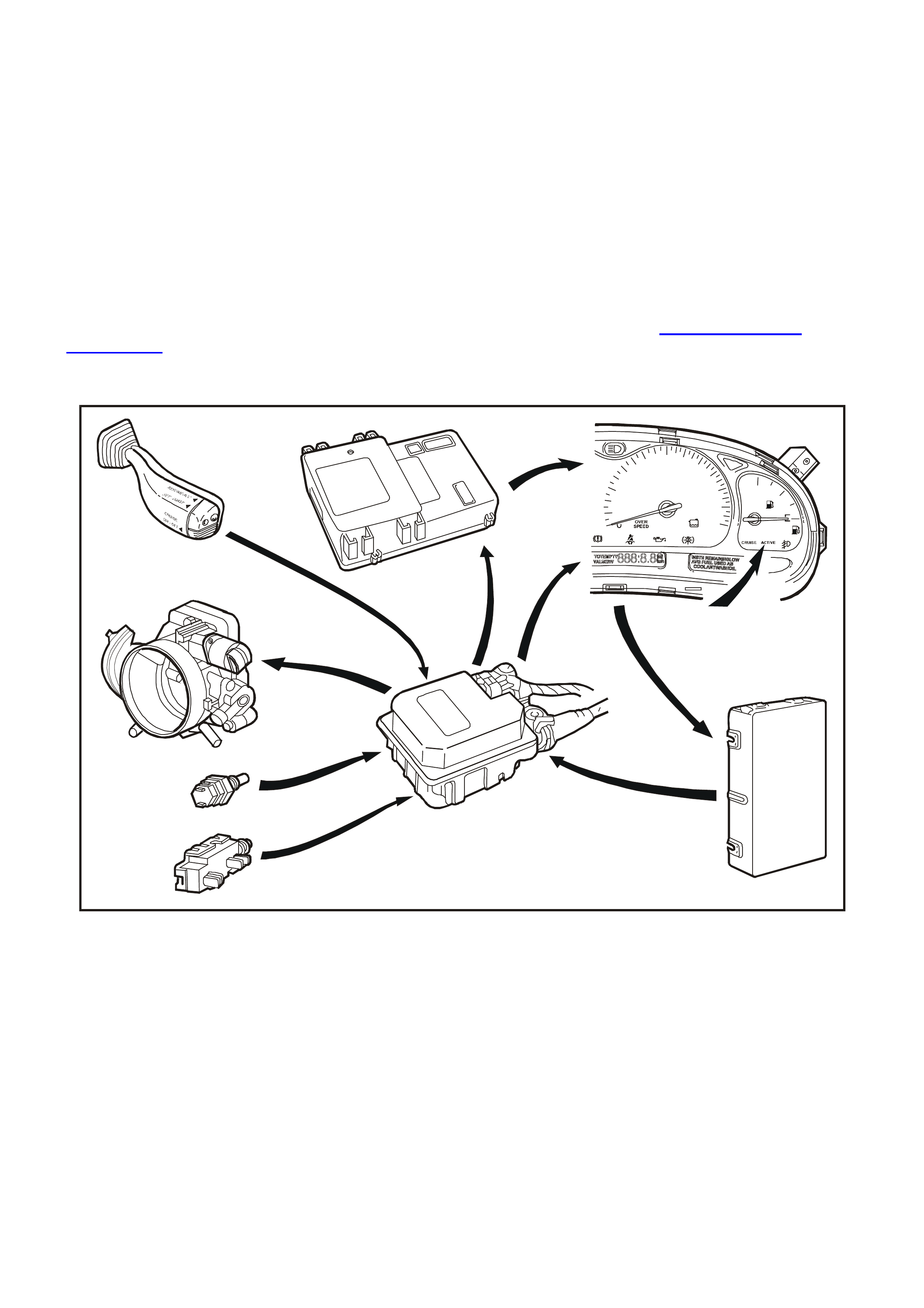
Fig. 12E-1 illustrates the component relationship for the cruise control system.
WH12E001
kmh
20
1
2
3
D
N
RP
40
60 80 100120
140
160 F
180
200
220
6
5
8
7
9
1
2
3
4
Figure 12E-1
1. Cruise control module
2. Brake pedal electrical release switch (Switch B)
3. Brake (Stop lamp) switch A
4. Throttle body
5. Cruise control switches
6. Body control module
7. Instrument cluster
8. CRUISE and ACTIVE lamps
9. Powertrain control module

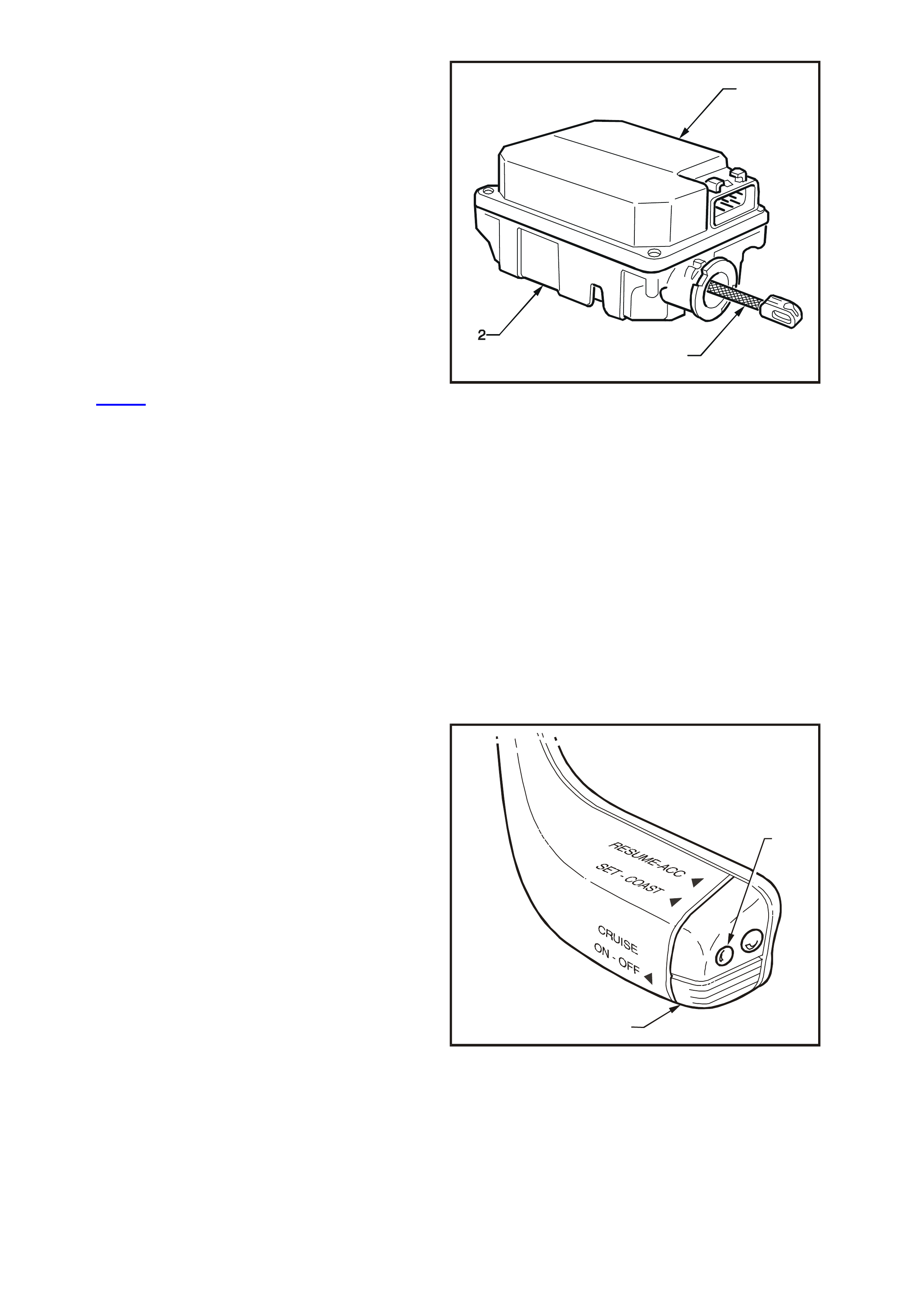
COMPONENTS
The cruise control module (1) is mounted forward
of the right-hand s trut tower (2) and adjacent to the
ABS module (3), regardless of the engine variant.
T212E002
2
13
Figure 12E-2
The cruise control module functionally integrates an
electronic controller (1) with an electric stepper
motor (2).
The electronic controller monitors vehicle speed
from a signal generated by the PCM which in turn,
operates the electric stepper motor.
The stepper motor, in response to the electronic
controller, adjusts the throttle position to maintain
the desired vehicle set speed. The electronic
controller is operated by the cruise control system
control switches (3) located at the tip of the
headlamp and turn signal stalk control switch
assembly.
T212E025
1
2
3
Figure 12E-3
Two switches, mounted on the br ake pedal suppor t
(1), disengage the cruise control system
electronically when the brake pedal (2) is
depressed.
The upper switch (3) is the cruise control electrical
release switch (Switch B). The two rear terminals
are used for the cruise control system.
NOTE: Using the f ront set of term inals will result in
the cruise control not functioning.
The lower switch (4) is the brake stop lamp switch
(Switch A), and is used to illuminate the st op lam ps
and signal the cruise control module to disengage.
With the brake pedal at rest, the stop lamp contacts
in the lower switch are open, and closed when the
brake pedal is depressed.
With the brake pedal at rest, the electrical release
contacts in the upper switch are closed, and open
when the brake pedal is depressed.
Both switches are used to signal the cruise control
module so that if one s hould fail, the sec ond switch
will still generate a signal to the cruise control
module to disengage the cruise control function.
T212E047
12
4
3
Figure 12E-4
The cruise control module comprises an electronic
controller (1) and electric stepper motor, solenoid
operated clutch and gear train assemblies (2), and
a connecting strap (3).
The electronic controller receives signals from the
cruise control electrical release switch, stop lamp
switch and vehicle speed output. It then generates
signals to control the stepper motor and solenoid
operated cruise control module clutch.
The electric stepper motor is a brushless type
motor with a four pole perm anent m agnet arm ature
and three phase stator. The motor provides torque
through a mechanical gear train to a control cable,
which actuates the throttle linkage.
When the brake pedal electrical release switch is
activated (brake pedal depressed) the stepper
motor begins to spin the motor back to the zero
motor position. If the signal at pin G (refer to
Fig. 12E-33) of the cruise control module is pulled
high, it will cause the stepper motor clutch to de-
energise in about 0.75 seconds . In most c ases, the
stepper motor will be in the zero position when the
module clutch is disengaged. This time delay
period is introduced to prevent the accelerator
pedal from slapping while the throttle is still held
open. The stepper motor relies on the throttle
return spring to r eturn the s tepper motor to the zero
position as the spring on the drum gear is not
strong enough to return the throttle/cruise to zero.
The internal components of the control module are
not serviceable.
CAUTION: Do not attempt to repair the control
module assembly if faulty. Unauthorised repair
of the control module will affect vehicle safety.
T212E004
1
3
Figure 12E-5
CRUISE CONTROL SWITCH OPERATION
Engaging the Cruise Control
W ith the ignition switched on, press the cruise ON-
OFF button (1). This will cause the CRUISE lamp in
the instrument cluster to illuminate, refer to
Fig. 12E-7, indicating power is on.
Accelerate the vehicle to the desired cruise speed
(above 40 km/h) and depress and release the
SET-COAST button (2), then release the
accelerator pedal.
T212E029
1
2
Figure 12E-6
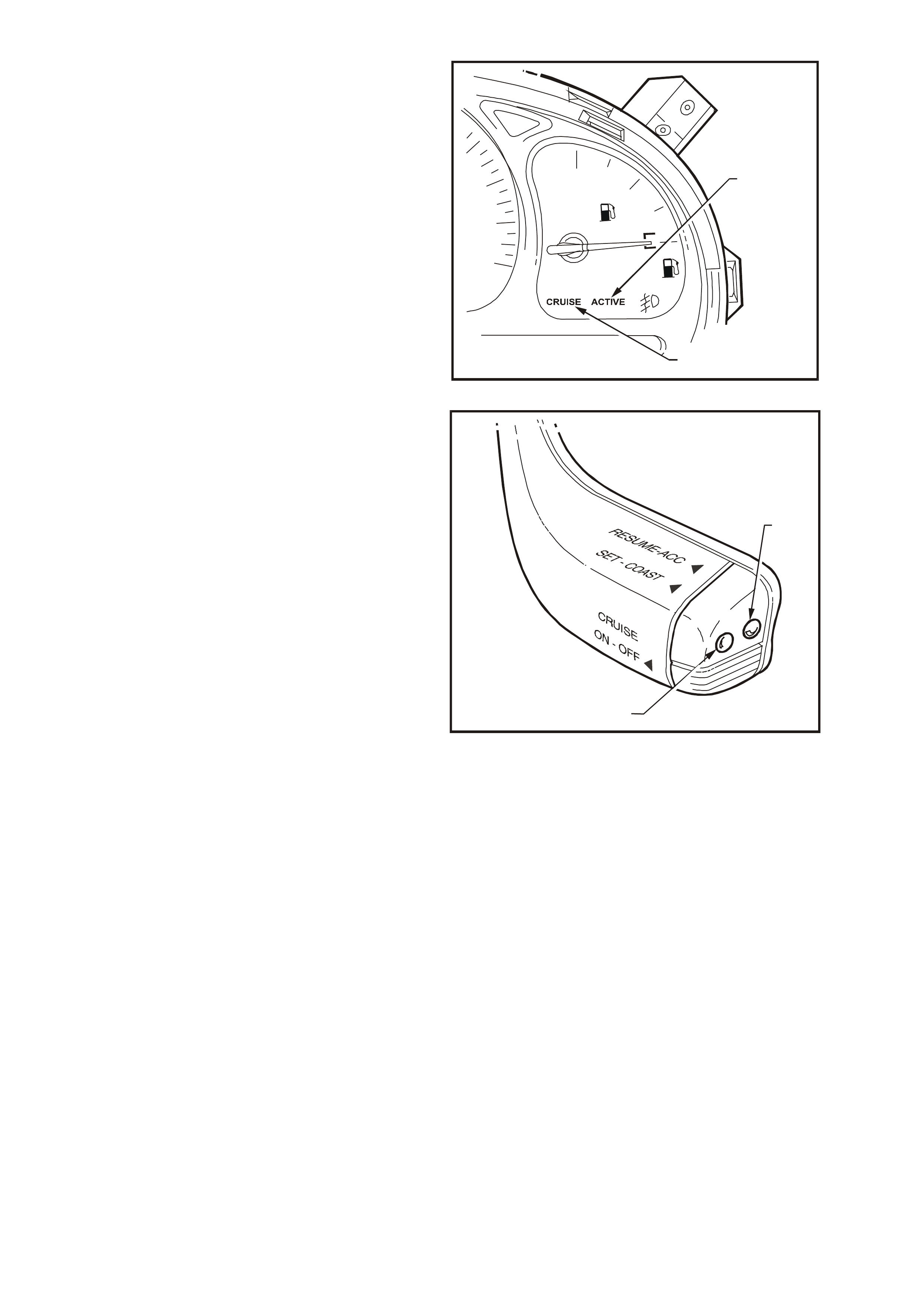
The CRUISE lamp (1) in the instrument cluster will
illuminate when the cruise control system is turned
on at the control switch located on the turn signal
stalk.
The ACTIVE lamp (2) in the instrument cluster will
illuminate when the cruise control system is
engaged. The cruise speed will be automatically
ma intained, provided the vehicle speed is above 40
km/h.
WH12E005
F
1
2
Figure 12E-7
To Change Cruise Speed
To reset the cruise control to a higher speed,
accelerate the vehicle to the desired speed,
depress the SET-COAST button (1) and release it.
Depressing the RESUME-ACC (2) button will cause
an increase in cruise speed and the vehicle will
accelerate at a controlled rate until the RESUME-
ACC button is released. The vehicle will now cruis e
at this higher set speed.
To decrease the cruise speed, press the SET-
COAST button. The vehicle will decelerate,
coasting to a slower speed at a controlled rate until
the SET-COAST button is released. The vehicle will
now continue to cruise at the reduced set speed.
NOTE: While holding the SET-COAST button, the
ACTIVE lam p in the instrum ent cluster ( ref er to Fig.
12E-7) will turn OFF. The ACTIVE lamp will
illuminate when the SET-COAST button is
released.
The cruise control switches also provide the facility
for TAP UP and TAP DOWN for smaller
incremental adjustments in vehicle cruise speed.
TAP UP is achieved by quickly depressing the
RESUME-ACC button and the cruise speed will
increase by 2.0 km/h for every TAP UP. Quickly
depressing the SET-COAST button (TAP DOWN)
will decrease the cruise control speed by 2.0 km/h
for every TAP DOW N. TAP DOW NS are limited to
the minimum cruising speed of 40 km/h.
T212E030
1
2
Figure 12E-8

To Override the Cruise Control System
The accelerator pedal may be depressed at any
time to overr ide the cruise control system . Release
of the accelerator pedal will return the vehicle to
the previous set cruise speed.
To Disengage the Cruise Control System
The system is disengaged when:
1. The brake pedal is depressed.
2. The ON-O FF button is depres s ed switching the
cruise control system to the STANDBY mode.
IMPORTANT: When vehicles are in a low traction
situation, the cruise control will disengage.
W hen the cruise control system is disengaged, the
ACTIVE lamp goes out but the CRUISE lamp
remains on.
To resum e the previous set cruise control memory
speed after braking, stopping, or pressing the ON-
OFF switch once, first accelerate, if required, until
the vehicle speed is greater than 40 km/h, then
press the RESUME-ACC button (for less than one
second). The vehicle will then automatically
accelerate to the previous cruise speed setting.
The cruise control module will retain the previous
set speed in memory for as long as the CRUISE
lamp is illum inated. Depressing the brak e pedal, or
pressing the ON-OFF switch once while the
ACTIVE lamp is on, will not erase the vehicle set
speed from the control module memory.
Pressing the ON-OFF switch while only the
CRUISE lamp is on or turning the ignition off, will
erase the previous cruise set speed from the
control module memory.
NOTE: Each time the ignition is cycled, the
CRUISE and ACTIVE lamps will go out. To
reactivate the cr uise control, the c ruise control ON-
OFF switch will have to be pressed.
2. SERVICE OPERATIONS
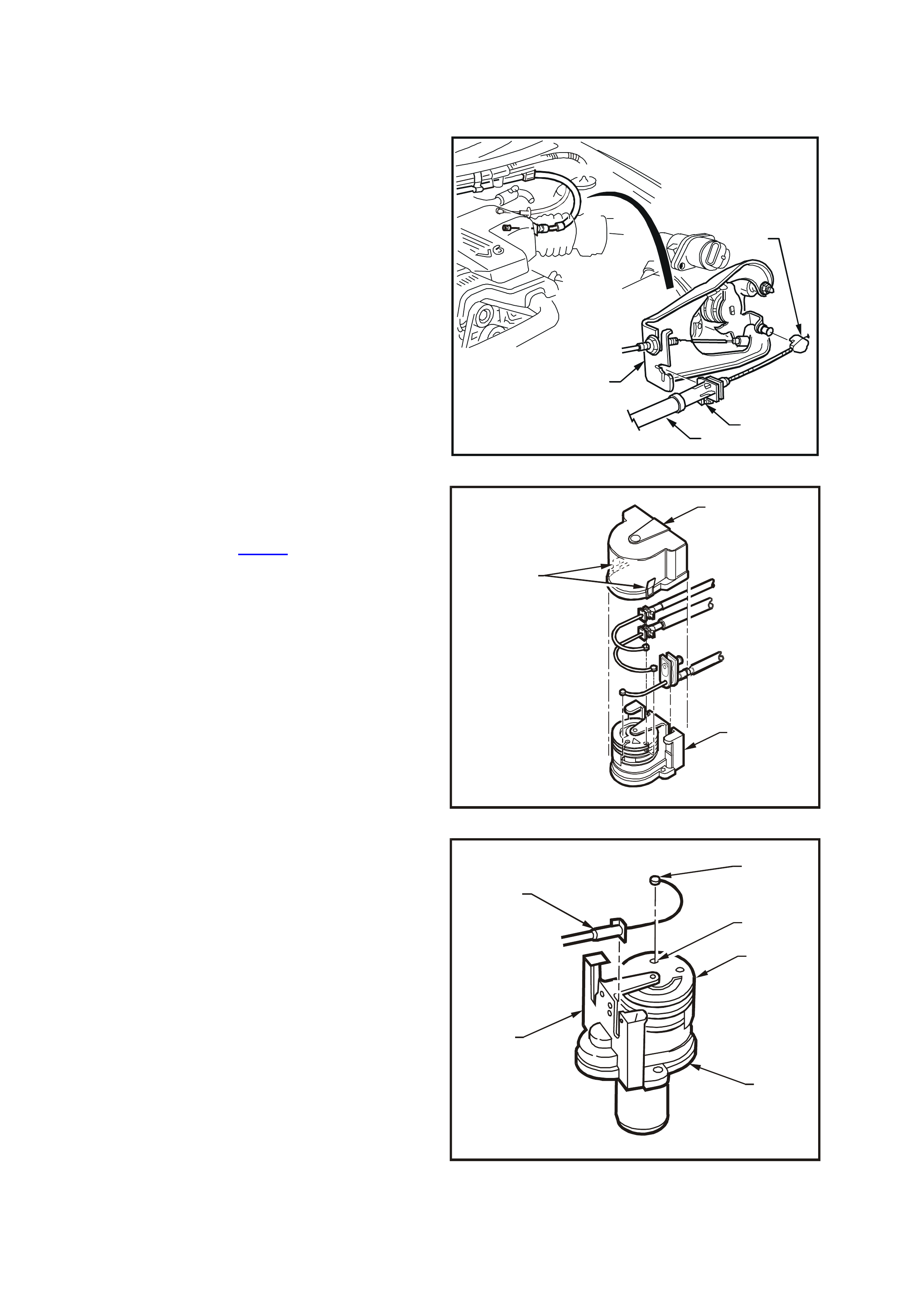
2.1 CRUISE CONTROL CABLE
REMOVE
1. On vehicles with V6 engine, push the outer
cable retaining tang (1) at the throttle cable
brack et (2) away from the throttle body and pull
outer cable (3) out of throttle cable bracket.
2. On vehicles with V6 engine, remove the inner
cable retaining clip (4) from the throttle body
linkage lever stud by pushing the retaining clip
off the stud with the aid of a screwdriver.
T212E006
1
3
2
4
Figure 12E-9
3. On vehicles with GEN III V8 engine, remove
cover (1) from thr ottle relaxer (2) by depressing
tabs (3) on both sides of cover. Refer to
Fig. 12E-10 and Fig. 12E-18.
T212E038
1
2
3
Figure 12E-10
4. Rotate top cam (1) of throttle relaxer (2) and
remove ferrule (3) of cruise control inner cable
from locating slot (4) in throttle cam. Lever out
retaining tang of outer cable (5) then lift cable
away from throttle relaxer mounting bracket (6).
T212E039
5
3
4
1
6
2
Figure 12E-11
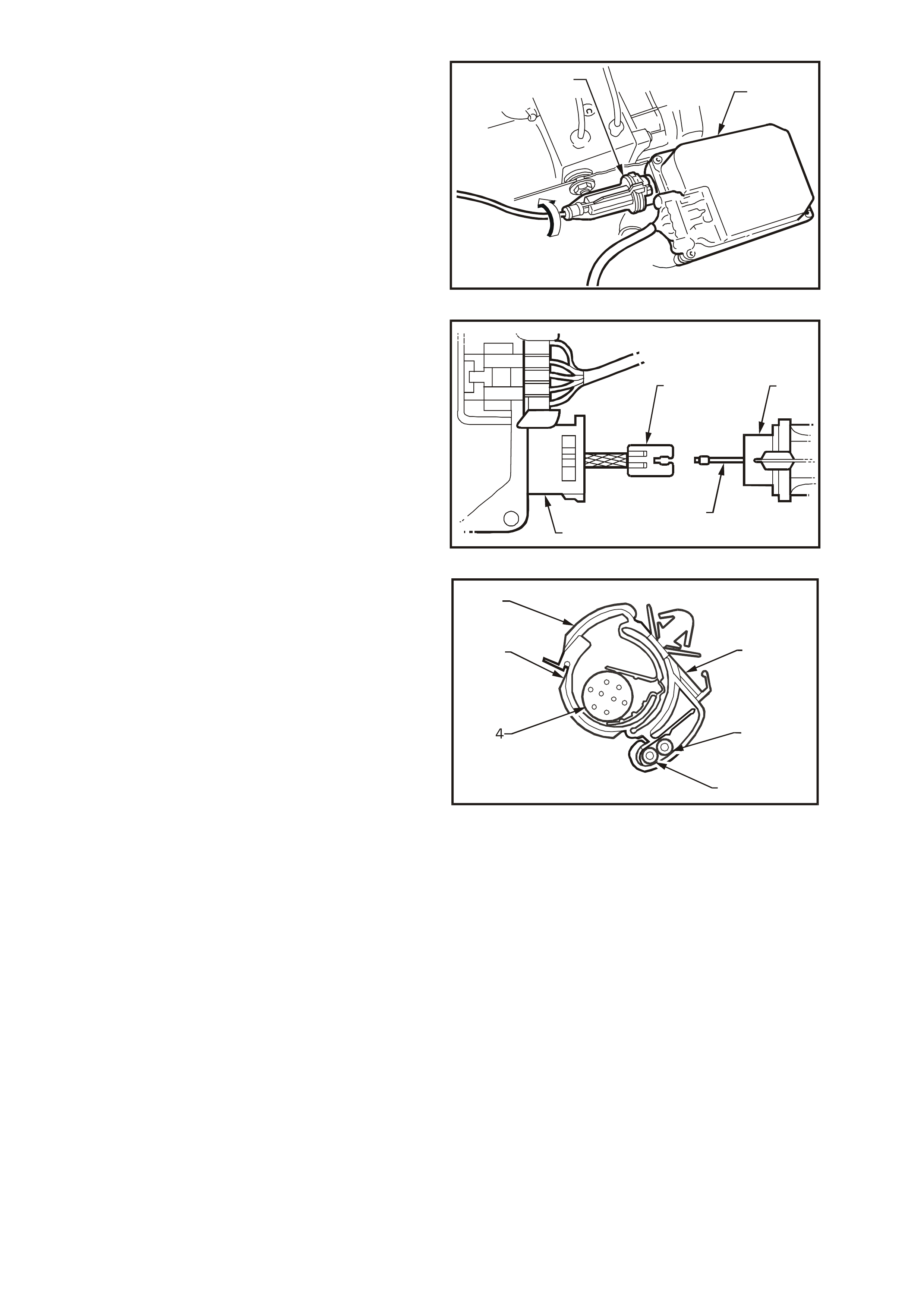
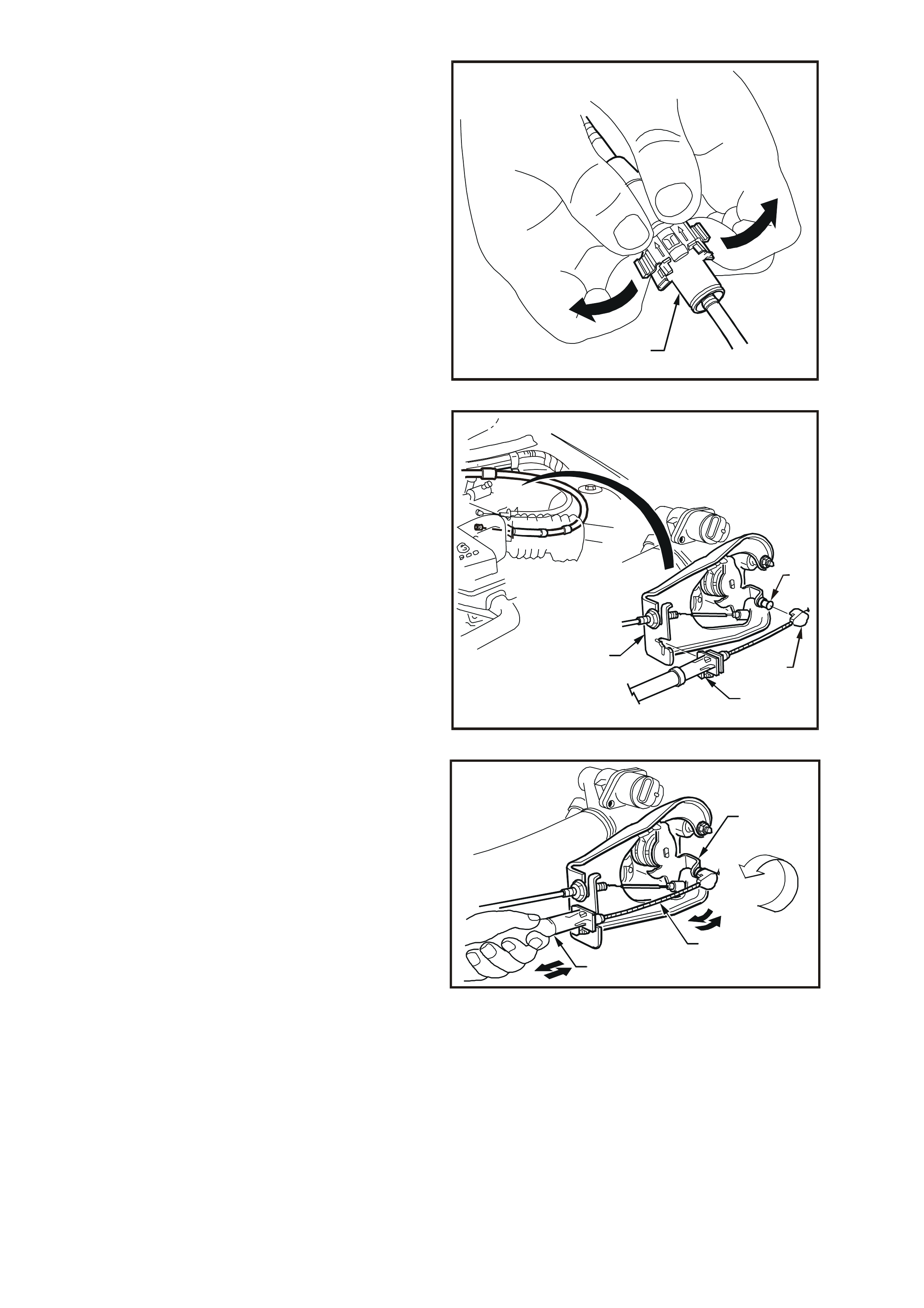
5. At the control m odule (1), turn the outer control
cable (2) towards the engine (approx. 45°) to
release the cable lock mechanism (3) from the
control module.
T212E009
3 1
2
45
O
Figure 12E-12
6. Pull the outer cable (1) fr om control m odule (2)
and disconnect inner cable (3) from electric
stepper motor strap end fitting (4) by lifting the
cable upward, approximately 45°, allowing it to
be released from the end fitting.
T212E010
CC
41
23
Figure 12E-13
7. Release cruise control cable from main wiring
harness/cable clip (1) by holding the upper
retention clip (2) and then pushing the lower
retention clip (3) inward and down to release
the powertrain wiring harness ( 4), throttle cable
(5) and cruise control cable (6).
NOTE: Depending on m odel and har ness /c able c lip
location, clip may also retain accelerator pedal
cable and wiper motor harness.
8. Remove cruise control cable.
WH12E011
2
31
6
5
Figure 12E-14
REINSTALL
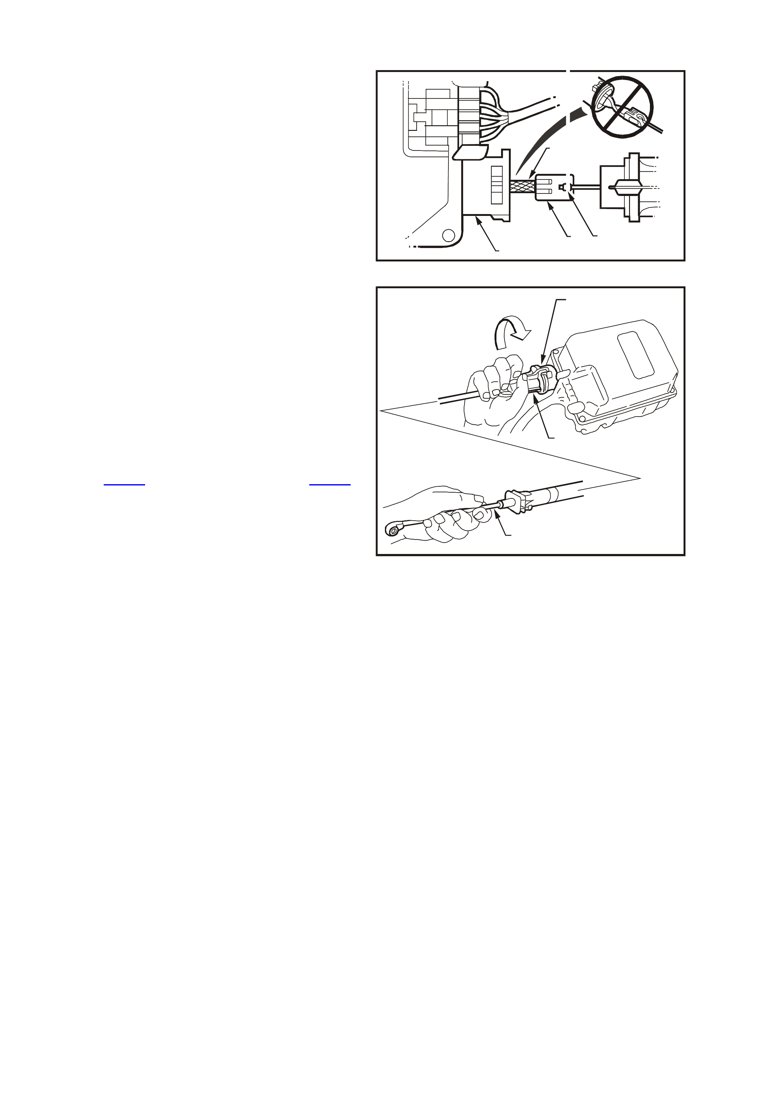
1. Ensuring that the m otor strap (1) is not twisted,
attach inner cable end (2) to the motor strap
end fitting (3) at the control module (4).
T212E012
CC
432
1
Figure 12E-15
2. W hile holding the inner cable (1) at the throttle
body linkage lever stud connection end, slide
outer cable (2) over the motor strap until the
outer cable sits flush with the control module
housing (3).
3. Turn outer cable towards the right-hand fender
(approx. 45°) to lock the outer cable locking
mechanism to the control module, refer to
Fig. 12E-16.
4. Ensuring that the cruise control cable is routed
correctly, lock the cable into the main wiring
harness/cable retention clips. Refer to
Fig. 12E-17 (V6), and Fig. 12E-18
( GEN III V8).
T212E013
45
o
3
2
1
Figure 12E-16
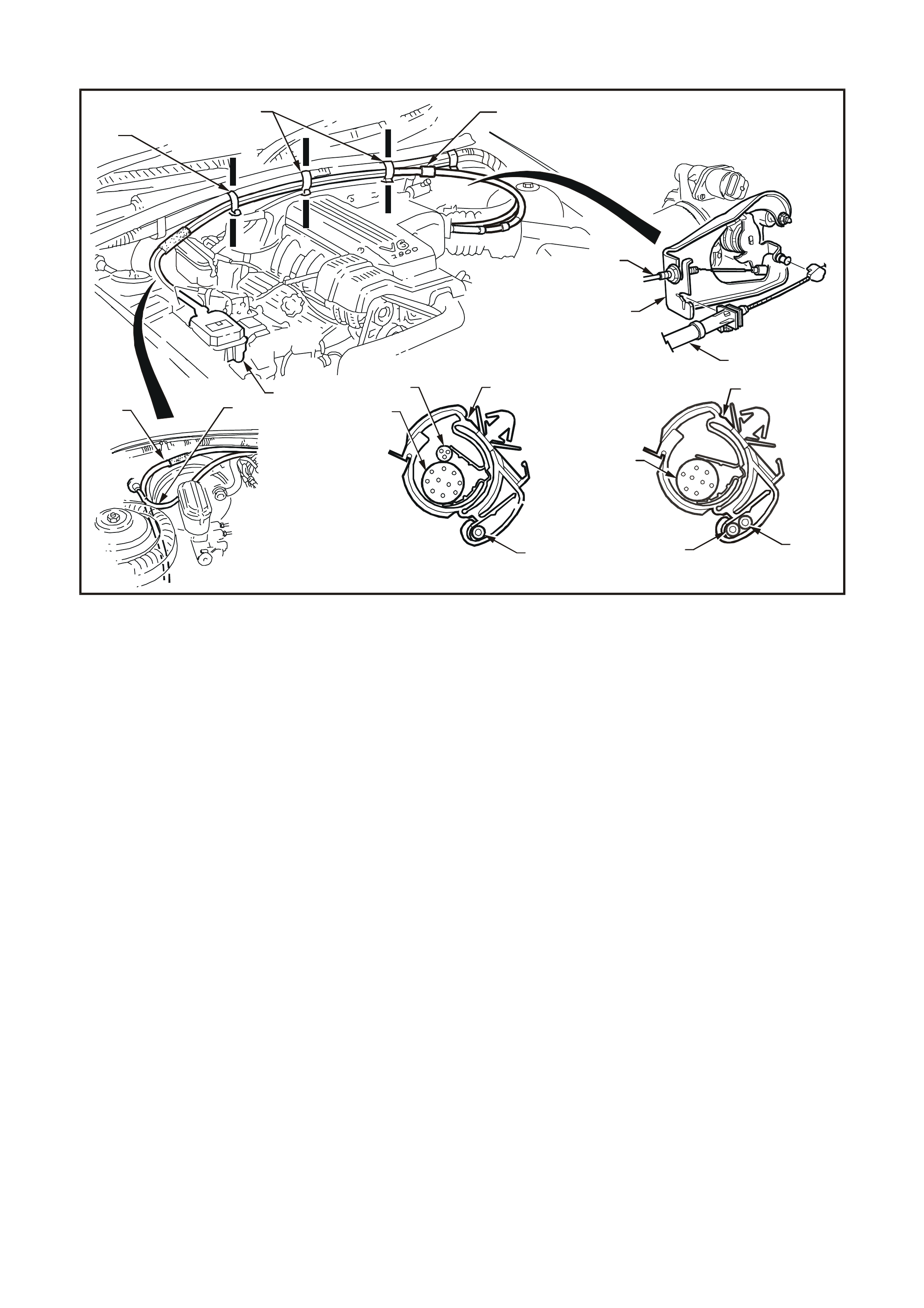
CABLE ROUTING: V6 ENGINE
WH12E014
123
578
1
2
9
A-A
65
4
1
A
A
B
BB
B
B-B
7
1
2
4
Figure 12E-17
1. Cruise control cable
2. Throttle cable
3. Cruise control module
4. Powertrain wiring harness
5. Harness/cable clip (Section A-A)
6. Wiper motor harness
7. Harness/cable clip (Section B-B, three places)
8. Cruise control outer cable adjuster/lock
9. Throttle cable bracket
NOTE: Cruise control cable routing for V6 Supercharged
engine is the same.
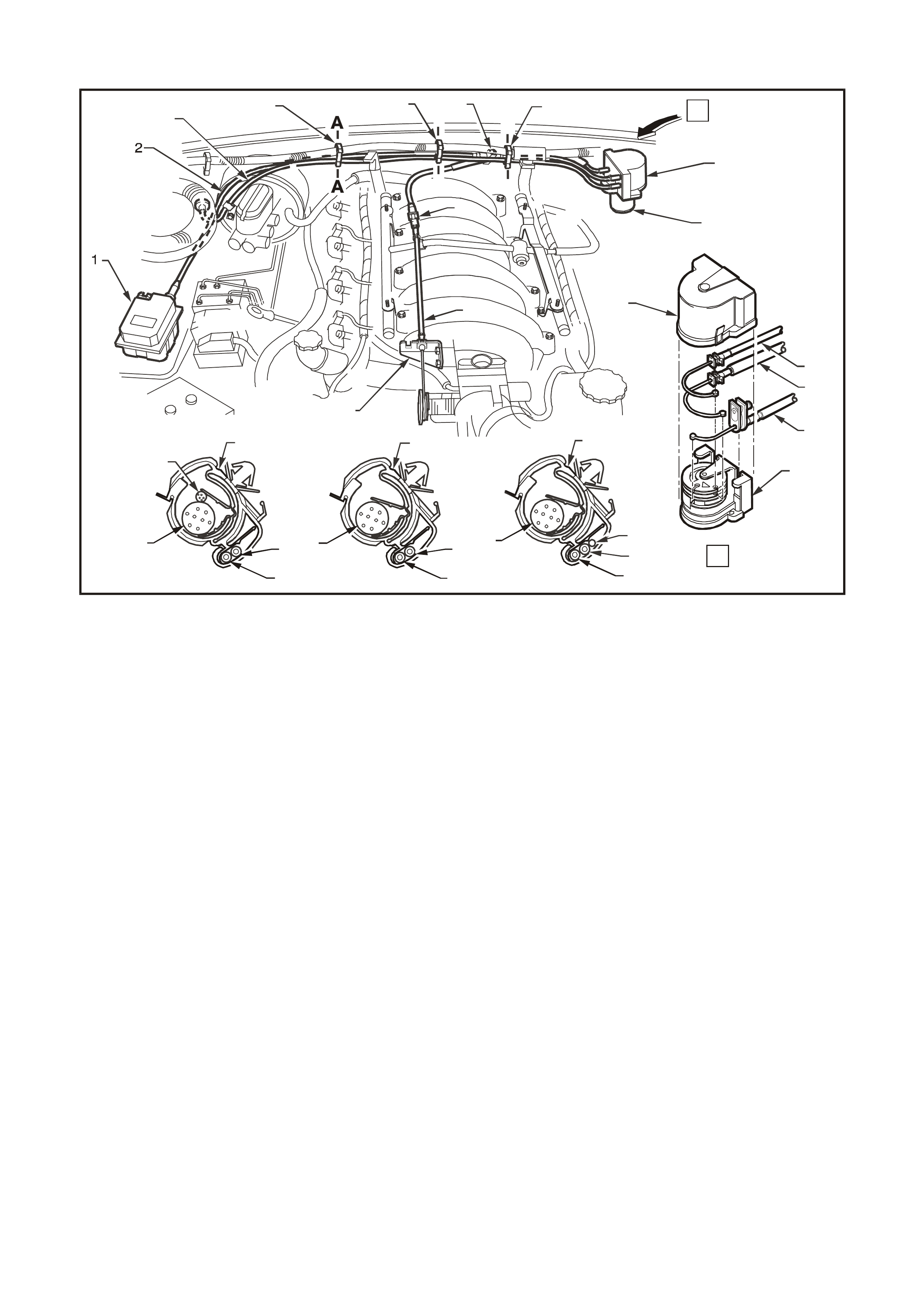
CABLE ROUTING: GEN III V8 ENGINE
T212E036
A-A
5
4
6
3
2
4
10
3
2
4
12
23
9
13
B-B C-C
B
B
C
C
A
A
10
9
12
11
10
3
7
14
13
6
9
3
2
14
Figure 12E-18
1. Cruise control module
2. Cruise control cable
3. Accelerator pedal cable
4. Powertrain harness
5. Wiper motor harness
6. Harness/cable clip (Section A-A)
7. Throttle cable bracket
8. Throttle outer cable adjuster/lock
9. Throttle cable
10. Harness/cable clip (Section B-B)
11. Cruise control outer cable adjuster/lock
12. Harness/cable clip (Section C-C)
13. Throttle relaxer
14. Throttle relaxer cover
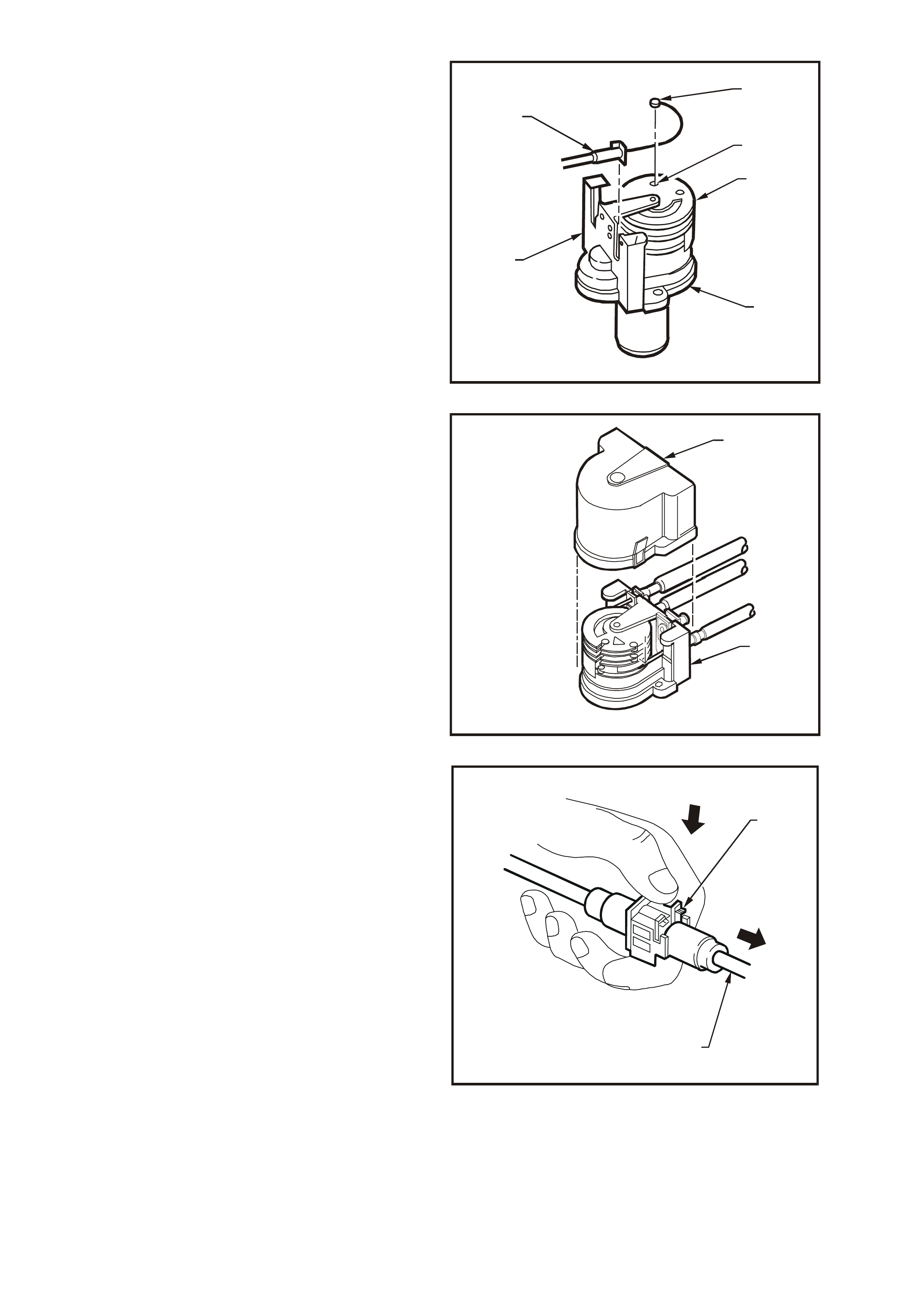
5. Unlock the cruise control outer cable by pulling
the lock tangs on the outer cable adjuster/lock
(1) in the direction indicated by the arrows in
Fig. 12E-19.
T212E016
1
Figure 12E-19
6. On vehicles with V6 engine, push the outer
cable retainer (1) into the throttle cable bracket
(2).
7. On vehicles with V6 engine, push the inner
cable retaining clip (3) onto the throttle body
linkage lever stud (4).
T212E031
1
23
4
Figure 12E-20
8. On vehicles with V6 engine, adjust the cruise
control outer cable (1) at the cable
adjuster/lock (refer to Fig. 12E-19) to achieve
minimum slack of the inner cable (2) while
ensuring that the throttle lever (3) is in the fully
closed position (4). Refer to Fig. 12E-21.
T212E020
1
3
2
4
Figure 12E-21
9. On vehicles with GEN III V8 engine, rotate top
cam (1) of throttle relaxer (2) and install inner
cable ferrule (3) into slot in cam (4). Ensure
that inner cable is properly in groove on cam.
Push outer cable retainer (5) onto throttle
relaxer mounting bracket (6) ensuring that the
cable retaining tang locks into the mounting
bracket.
T212E039
5
3
4
1
6
2
Figure 12E-22
10. On vehicles with GEN III V8 engine, install
cover (1) on throttle relaxer (2).
T212E042
1
2
Figure 12E-23
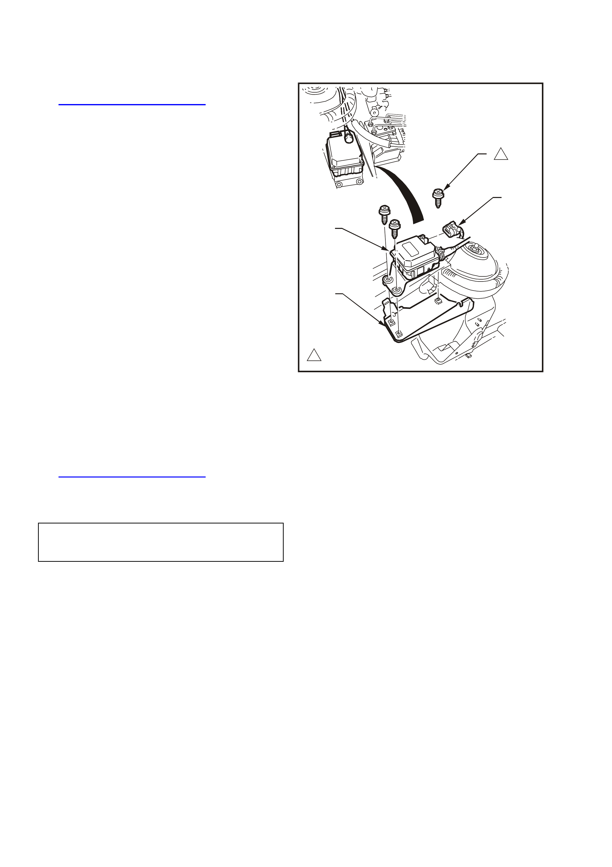
11. Allow the internal spring of the cable
adjuster/lock mechanism (1) to take up the
free play of the outer cable (2). Push down on
the outer cable lock ing retainer to fix the outer
cable to the corr ect self adjusted length. Ref er
to Fig. 12E-24.
NOTE: After the cable is fitted, ensure that the
throttle opens without binding and returns to the
fully closed position under throttle return spring
tension.
T212E021
2
1
Figure 12E-24
2.2 CRUISE CONTROL MODULE
REMOVE
1. Remove the cruise control cable, refer to
2.1 CRUISE CONTROL CABLE in this Section.
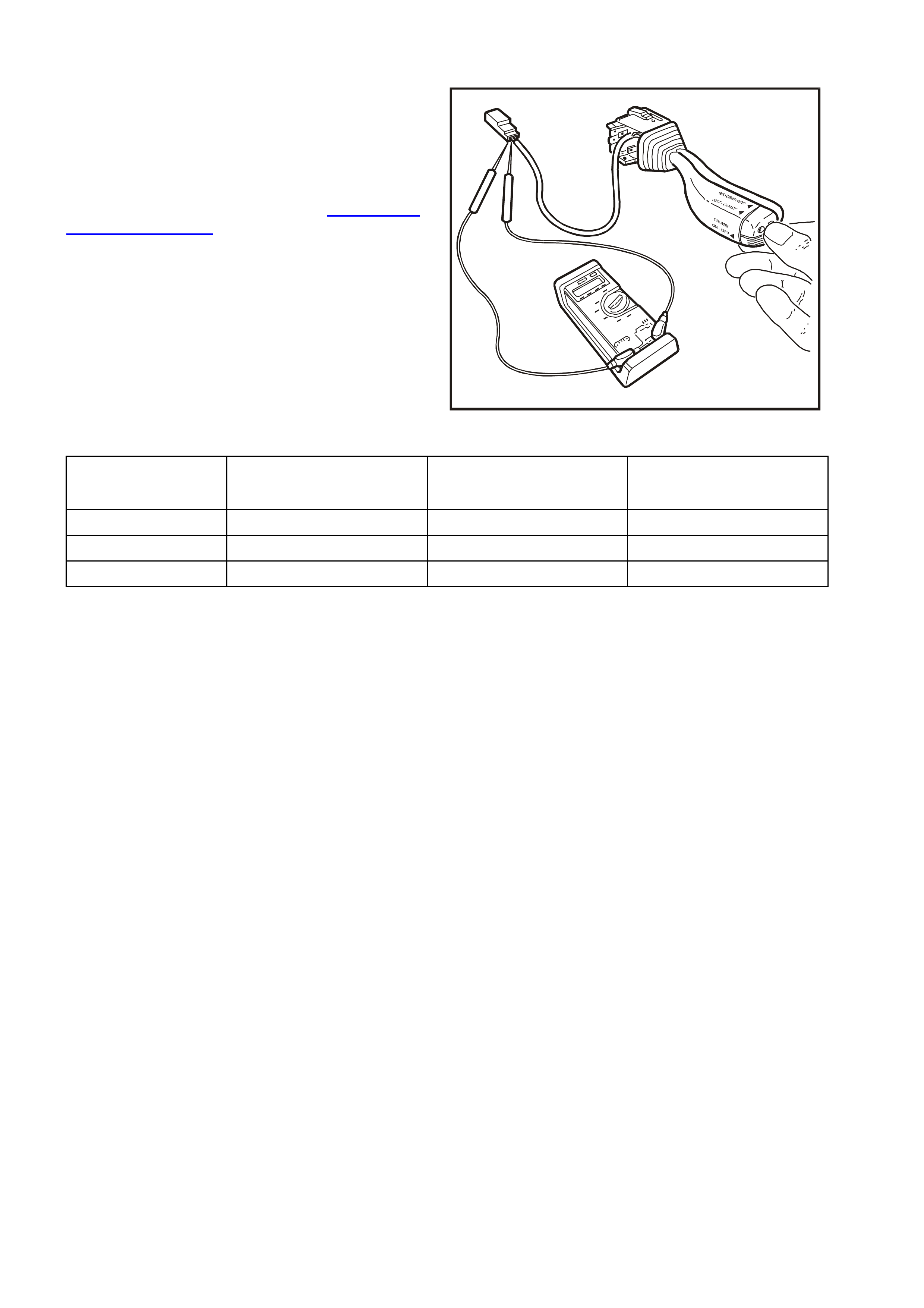
2. Pull up tang on wiring harness connector (1),
and pull connector from control module (2).
3. Remove the three screws (3) securing the
control m odule to the ABS/cruis e c ontro l module
mounting bracket (4) and remove control
module.
T212E022
1
1
2 ~ 5 Nm
4
3
1
2
Figure 12E-25
REINSTALL
Installation of the cruise control module is the
reverse of the removal operation, noting the
following:
1. To install the cruise control cable, refer to
2.1 CRUISE CONTROL CABLE in this Section.
2. Tighten all fasteners to the correct torque
specification.
CONTROL MODULE
SECURING SCREW
TORQUE SPECIFICATION 2 – 5 Nm
3. Connect the wiring harness connector ensuring
that the connector tang is secure.
2.3 CRUISE CONTROL SWITCH ASSEMBLY
REMOVE AND REINSTALL
The cruise control switches are integrated with the
headlamp and turn signal control switch stalk
located to the right of the steering column.
Removal and installation instructions for the right-
hand switch stalk are described in Section 12B
LIGHTING SYSTEM of the VT Series I Service
Information.
CHECKING SWITCH CONTACTS
With the cruise control system control switch lead
disconnected from the main wiring harness, check
the cruise control switch contacts as follows:
Attach an ohmmeter to the appropriate terminals
nominated in the following chart and depress and
hold switches as indicated.
T212E033
Figure 12E-26
SWITCH OHMMETER CONNECTED RESISTANCE RESISTANCE
BETWEEN SWITCH DEPRESSED SWITCH RELEASED
OFF-ON RED WIRE & GREY WIRE APPROXIMATELY 470 ΩOPEN CIRCUI T
SET/ACCEL BLUE WIRE & RE D WIRE APPROXIMATELY 470 ΩOPEN CIRCUI T
RESUME/ DECEL RED WIRE & GREE N WIRE APPROXIMATELY 470 ΩOPEN CIRCUI T
If the resistance is not to specification, replace the
cruise contro l switch assembly.
2.4 STOP LAMP SWITCH (SWITCH A)
TESTING SWITCH CONTACTS
1. Check adjustment of the stop lamp switch (1),
refer to the following switch installation and
adjustment procedure and adjust the switch as
required.
Ensure that the stop lam ps are operating when
the brake pedal is depressed.
If stop lamps are not operating, repair as
necessary, refer to Section 12B LIGHTING
SYSTEM of the VT Series I Service
Information.
2. Remove wiring harness connector (2) from the
terminals of the stop lamp switch (1).
3. Connect an ohmmeter across the switch
terminals and the ohmmeter should indicate
open circuit with the brake pedal at rest.
Depress the brake pedal and the ohmmeter
should indicate continuity.
4. Replace the switch as per the following
removal procedure if the tests prove the switch
to be faulty.
5. If the test proves the switch to be serviceable,
connect the wiring harness connector to the
switch.
T212E045
2
3
1
Figure 12E-27
REMOVE
1. Disconnect wiring harness connectors (2) from
the stop lamp switch (1).
2. Rotate switch anticlockwise and remove from
the mounting nut (3).
REINSTALL AND ADJUST
1. Install the stop lamp switch (1) into the
mounting nut (2) on the brake pedal support
(3).
2. With the brake pedal (4) in its rest position,
adjust the switch to the clearance dimension
shown in Fig. 12E-28.
3. Connect wiring harness connector to the
switch.
T212E046
1
3
2
4
6 0.5mm
A
A
1
3
4
2
A
-A
+
Figure 12E-28
2.5 ELECTRICAL RELEASE SWITCH (SWITCH B)
TESTING SWITCH CONTACTS
1. Check adjustment of the electrical release
switch (1), refer to the following switch
installation and adjustment procedure and
adjust the switch as required.
2. Remove wiring harness connector from rear
most terminals (2) of switch.
3. Connect an ohmmeter across the switch
terminals and the ohmmeter should indicate
continuity with the brake pedal at rest.
Depress the brake pedal and the ohmmeter
should indicate an open circuit.
4. Replace the switch as per the following
removal procedure if the tests prove the switch
to be faulty.
5. If the test proves the switch to be serviceable,
connect the wiring harness connector to the
switch.
T212E023
1
3
2
Figure 12E-29
REMOVE
1. Disconnect wiring harness connectors (1) from
electrical release switch (2).
2. Pull switch from tubular clip (3).
3. If necessary, remove clip from brake pedal
support (4).
T212E024
1
2
4
3
Figure 12E-30
REINSTALL AND ADJUST
1. If removed, install the tubular clip into the
mounting hole of the brake pedal support.
2. Holding the brake pedal in its depressed
position, install switch into tubular clip. Push
switch forward until the switch body locates in
the clip.
NOTE: Audible click s will be heard as the threaded
portion of switch assembly is pushed into the
tubular clip toward the brake pedal.
Pull brake pedal fully against pedal stop until
audible ‘click’ sounds can no longer be heard.
(Switch assembly is pushed back out from the clip
to provide correct switch position adjustment).
Depress the brake pedal again and repeat above
procedure to ensure that the switch adjustment is
correct (no click sounds).
3. Connect wiring harness connector to the
switch.

3. DIAGNOSIS
3.1 PRELIMINARY DIAGNOSIS AND INSPECTION
NOTE: The cruise control system will disengage or fail to engage whenever the LOW TRAC lamp is illuminated in
the instrument cluster, (i.e. traction control system is in operation) and will not engage or re-engage until the LOW
TRAC lamp turns off.
When a vehicle is suspected of having a cruise control system operation malfunction, it is important to carry out the
following preliminary diagnosis. This diagnosis should be used to determine whether the cruise control system
problem is the result of an actual system defect, or the result of a problem with some other vehicle component.
Also, some cruise control system complaints may be a misunderstanding by the driver about how the cruise control
system functions. In that case, the operation of the system should be explained in a manner the driver understands.
A practical demonstration is very useful to explain system operation.
If it is decided the cruise control system is at fault, perform a visual inspection of all components in the system.
Cruise control system malfunctions can be caused by mechanical, electrical, or a combination of both problems.
Things to check are:
1. Switch inputs to cruise control module.
2. Dirty, corroded, or loose electrical connections.
3. Damaged or incor rec tly adjusted stop lamp switch ( Switch A). Ref er to 2.4 ST OP L AMP SW IT CH in this Sec tion
for test and adjustment procedure.
4. Damaged or incorrectly adjusted electrical release switch (Switch B). Refer to
2.5 ELECTRCAL RELEASE SWITCH in this Section for test and adjustment procedure.
5. Binding or sticking throttle linkage.
6. Broken components (e.g. cruise control cable).
7. Bare, broken or disconnected wires.
8. Adjustment of control cable, refer to 2.1 CRUISE CONTROL CABLE in this Section.
9. On vehicles fitted with GEN III V8 engine and traction control, ensure that the throttle relaxer is functioning
correctly. Refer to Section 12L A BS & ABS/ETC of the VT Series II Service Information.
If preliminary inspection reveals no problem, and the system is malfunctioning, refer to
3.3 SELF DIAGNOSIS TEST in this Section.
NOTE: Verify the problem exists before attempting any repairs. Sometimes normal operating characteristics may be
misunderstood as a problem.

3.2 CRUISE CONTROL SYSTEM FUNCTIONAL CHECK
The following procedure should be used to check the operating modes of the cruise control system. This procedure
should always be used after repair work has been completed on the cruise control sy stem.
ROAD TEST PROCEDURE
1. Check ON-OFF activation: Ignition on, depress the cruise control ON-OFF button to turn the system on;
system CRUISE lamp should illuminate.
2. Check the low speed inhibit: Drive vehicle at 30 km/h. Depress SET-COAST button and release. Cruise
control must not engage and only the CRUISE lamp should be illuminated.
3. Check set speed: Drive vehicle at a steady speed of 60 km/h. Depress SET-COAST button and release.
Cruise control should engage at approximately 60 km/h and both the CRUISE and ACTIVE lamps must
illuminate.
4. Check brake release: With cruise control system engaged, depress brake pedal. The cruise control must
release the throttle, allowing vehicle speed to drop. The system must not re-engage when the brake pedal is
released. The ACTIVE lamp must go out but the CRUISE lamp will remain on.
5. Check resume feature: W ith vehicle speed at approxim ately 50 km /h, depress the RESUME-ACC button and
release. The vehicle should accelerate to approximately 60 km/h and the CRUISE and ACTIVE lamp should
illuminate again.
6. Check coast feature: Depress the SET-COAST button and hold. Only the ACTIVE lamp must go out. Allow the
vehicle speed to drop to 50 km/h and release SET-COAST button. The cruise control should hold the vehicle
speed at approximately 50 km/h and both the ACTIVE and CRUISE lamps should be illuminated.
7. Check accelerator feature: Depress the RESUME-ACC button and hold. The vehicle speed should begin to
increase. Allow the speed to inc rease to 60 km /h and r elease switch. T he cr uise contr ol s hould hold the vehicle
speed at approximately 60 km/h. Both the ACTIVE and CRUISE lamps should be illuminated.
8. Check coast down mode:
a) Press and release the ON-OFF button. T he vehicle should begin to slow down (this has the same effect as
holding the SET-COAST button). In this mode, the cr uis e is deactivated and allows the vehic le to s low down but
the CRUISE lamp remains illuminated. Allow the vehicle to slow to approximately 50 km/h then press and
release the RESUME-ACC button. The vehicle m us t return to approx imately 60 km/h and both the CRUISE and
ACTIVE lamps should be illuminated.
b) Press and release the ON-OFF button and allow vehicle to slow to approximately 50 km/h again and press
the SET-COAST button. The vehicle speed must hold at 50 km/h and both the CRUISE and ACTIVE lamps
should be illuminated.
c) Press the ON-OFF button again and allow the vehicle to coast down. Only the CRUISE lamp should be
illuminated.
d) Press the ON-O FF button again while in coas t down mode ( Step c) to f ully turn the cruise control system of f.
Both the CRUISE and ACTIVE lamps must go out.

3.3 SELF DIAGNOSTIC TEST
To provide a means of checking brake switches, cruise release switch, speed sensor inputs and electro-motor
operation, the cruise control system incorporates a self diagnostic facility.
Following the Self Diagnostic Test is a detailed Diagnostic Chart to pin point the cause of a cruise control system
malfunction. Refer to 3.5 CRUISE CONTROL SYSTEM DIAGNOSTIC CHART in this Section.
Carry out the Self Diagnostic Test as outlined.Jack up vehicle and support on safety stands. Refer to
Section 0A GENERAL INFORMA TION of the VT Series I Service Information for the location of jacking points.
Ensure drive shafts are horizontal.
Follow Steps 1 – 23 in the SWITCH DIAGNOSTIC TEST CHART (next page) following and perform the function as
requested. If at any stage during this test the system does not function as nominated (CRUISE or ACTIVE lamp
illumination), repair fault as necessary.
NOTE: If at any time during Steps 1 – 23 of the diagnostic test the ignition is switched off, the cruise control system
will exit diagnostic mode and return to normal operating conditions.

SWITCH DIAGNOSTIC TEST CHART
STEP PROCEDURE LAMPS COMMENTS
CRUISE ACTIVE
1. Turn ignition OFF OFF OFF Clears m emory of any pre-s et speed.
2. Press & Hold
ON-OFF button OFF OFF Triggers di agnostic t est. ON-OFF button must be held until S t ep 13.
3. Turn ignit ion ON ON OFF
4. Wait 5 seconds ON OFF Waits for LOW TRAC warning lam p t o switch OFF (if fi t ted).
5. Press & hol d
SET- COAST button ON ON Tests SET-COAST function of cruise control switch assembly.
6. Release
SET-COAST button ON OFF
7. Press & hol d
RESUME-ACC
button
ON ON Checks RESUME-ACC function of cruise control switch assembly.
8. Release
RESUME-ACC
button
ON OFF
9. Press & hol d brake
pedal ON ON Checks cruise control electrical release switch (switch B).
10. Release brake pedal ON OFF
11. Press & hol d brake
pedal ON ON This St ep i s included f or vehi cles with manual transmiss i on. Although not
applicable to WH Series models, this Step must s t ill be conducted in order
to complete the switch diagnos t i c test .
12. Release brake pedal ON OFF
13. Release ON-OFF
button ON ON Enters the second s tage of the diagnos tic mode to chec k the ON-OFF
switch and c rui se control warning lamps.
14. Press & hold
ON-OFF button OFF OFF
15. Press & hol d brake
pedal OFF ON Checks stop lamp switch (switch A) and cruise control switch inputs to
cruise control module. If not func t i oni ng, repair as nec essary.
16. Release brake pedal OFF OFF
17. Press & hol d brake
pedal OFF ON
18. Release brake pedal OFF OFF
19. Release ON-OFF
button OFF ON Enters final s t age of diagnosti c mode, al l owing vehic l e to be road test ed
without having to hold cruise c ont rol function buttons.
20. Press & hol d brake
pedal
After motor s troking
OFF
OFF
OFF
ON
Checks stepper motor and cable operation.
Stepper motor will stroke and return to rest (c los ed throttle) s t ate. If not
funct i oni ng, repai r as necessary.
21 Hold brake pedal &
start engi ne OFF X ACTIVE lamp can be eit her ON or OFF.
22. Select DRIVE , dri ve
vehicle & monitor
ACTIVE lamp
OFF FLASH ACTIVE lamp will flash with vehicle speed signal.
Checks speed sender input t o cruise c ont rol module. If not f unctioning as
specified, replac e cruise control modul e.
23. Select PARK &
switch engine OFF OFF OFF Ends diagnosti c mode. Returns cruise control t o normal operati ng
conditions.
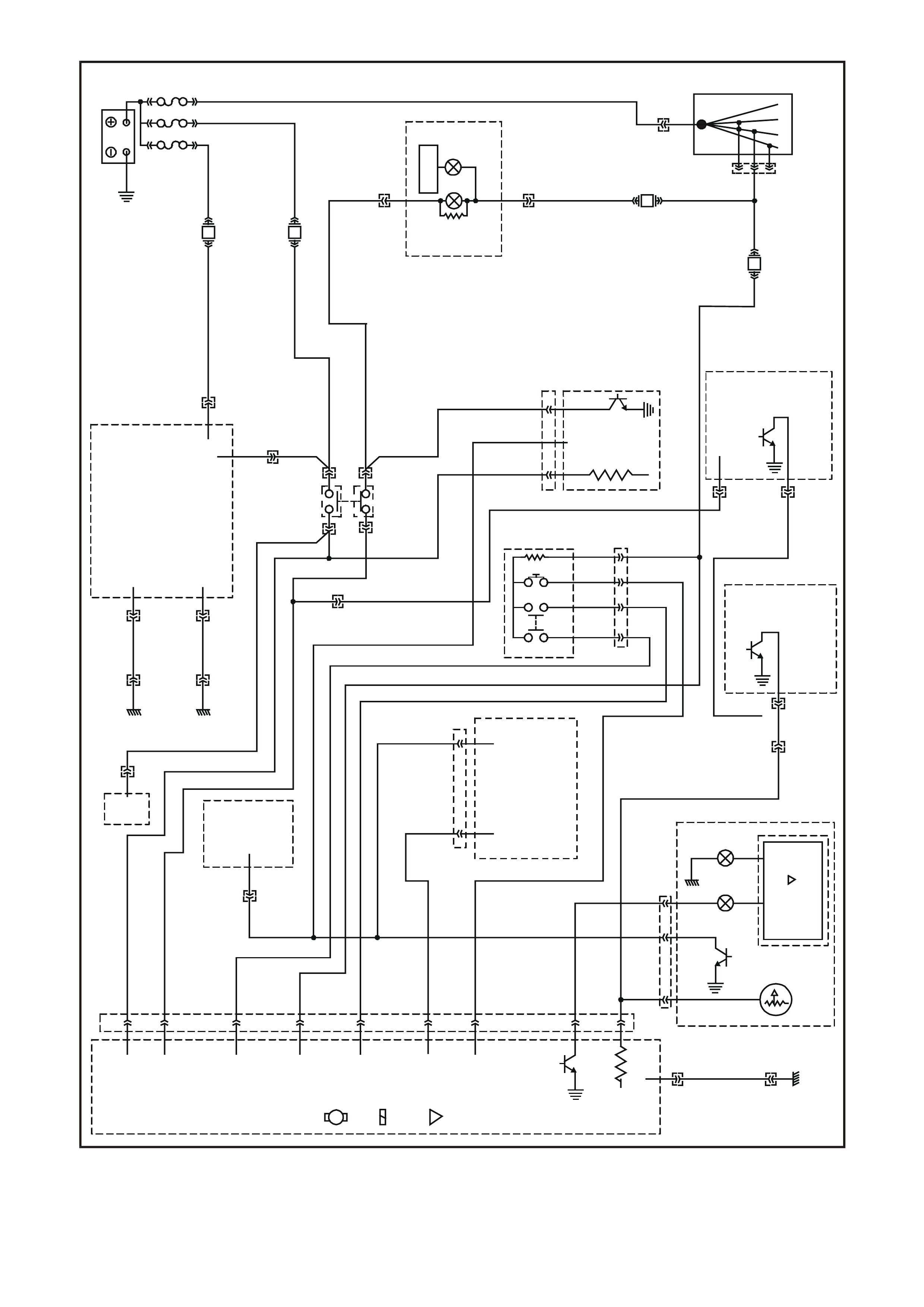
3.4 CRUISE CONTROL SYSTEM CONNECTORS & CIRCUIT DIAGRAM
V
(120)
LG
(200)
G
(117)
BLU
(15)
LBL U
(14)
BLU/R
(20)
BR
(9)
O/ Y
(1240)
LG
(24)
O/ B
(540)
BLU/O
(46)
BR/ B
(199)
Y/ BLU
(116)
BLU/B
(1 15)
V/ R
(192)
YB39
BODY HARNESS CONNECTOR
FGHJK
EDCB
A
BLU/R
P
(20)
(139)
B
BR
(150)
(86)
W
V/ W
(85)
(123)
GY/ G
BLU
(397)
(84)
GY
(83)
GY/ B
(87)
YE56
CRUISE CON TROL
CONNECTOR
Y
B66
I NSTRUMENTS CONN ECTOR
10
20 1
11
B/ Y
(155)
GY
(8)
BR/ W
(19)
BLU/Y
(10)
T
(30)
V/ W
(123)
BR/ O
(33)
BR
(25)
V/ R
(234)
W
(85)
BLU
(15)
Y/ R
(88)
G/ W
(122 0)
BLU/ B
(946)
LBL U
(14)
G
(875)
O/ Y
(1340)
P/ BLU
(44)
BR/ R
(121)
WH12E027
116
19
27
20
31
26
15
B/O
R
R
B
Y/ R
G
B/W
BR/ R
R/ W
(154)
(23)
(23)
(150)
(88)
(875)
(1427)
(121)
(1429)
BLU
B
R
W
GY
BR
Y
V
(883)
(882)
(873)
(872)
(833)
(830)
(885)
(884)
G/ W
BLU/B
O/ W
BLU/R
R
(1220)
(863)
(1426)
(20)
(855)
YE98
A.B.S./ E.T.C. CONTROL
MODULE & MODULATOR
CONNECTOR
BR
(86)
Y/ R
(88)
Y
B12
STOP LAM PS SWITCH B
CONNECTOR
YB161
STOP LA MPS SWITCH A
CONNECTOR
BLU/R
(20)
O/ BLU
(640)
P/ BL U
(44)
6
12
BR/ W
(19)
1
7
Y
B87
E.C.C. CONNECT OR
GY
(8 )
B/ Y
(155)
B/ R
(292)
Y
(51)
B/ R
(64)
Y/ B
(52)
G/ W
(1220)
LG/ B
(735)
BLU/B
(734)
GY/ B
(87)
GY/ G
(397)
BLU
(84)
P
(139)
YB152
CRUISE CON TROL S WITCH
CONNECTOR
Y
B44
IGNITION SWITCH
CONNECTOR
R
(2)
V
(5)
P
(3)
BR
(4)
Figure 12E-31
WH12E043
Y/R
Y
O/BLU
GY/R
P/B
(143)
(43)
(640)
(1391)
(39) 20
28
Y/B
(260)
B/R
(1144)
R/W
(261)
21 12
W/BLU
(494)
LBLU
(161)
W
(160)
13 6
GY/B
(96)
B/LG
(556)
W/G
R/B
V/R
BR /G
Y
G/W
Y/B
W
W/R
(1220)
(1221)
(229)
(271)
(266)
(1220)
(272)
(717)
(308)
1
7
YB175
B.C .M CONNECTOR E (3 )
B
(1150)
BLU/W
(97)
GY
(83)
LBLU
(94)
O/W
(840)
YB193
V6 P.C.M CONNECTOR (1)
V
GY
GY/B
V
V/B
BR
BR
G/W
G/W
W/R
O/W
(430)
(1412)
(1413)
(412)
(413)
(418)
(418)
(897)
(897)
(815)
(1426)
C16
D16 D1
C1
W
(423)
T/B
(424)
T
(832)
LBLU/B
(647)
LG/W
(443)
LG/B
(444)
LBLU/B
(442)
LBLU
(441)
BLU/W
(831)
B/R
(453)
B
(630)
BR/W
(792)
GY/R
(422)
LG
(1222)
Y/B
(1223)
G/Y
(428)
V/W
(123)
Y
(173)
BR
(90)
O/B
(473)
Y
(196)
B/G
(151)
O/V
(440)
LBLU
(14)
O/B
(740)
BLU
(15)
V
(782)
1
6
5
12
YB174
B.C.M. CONNECTOR B(2 )
GY
(8)
B/W
(1128)
B/Y
(28)
GY /BL U
(492)
B/Y
(155)
O/B
(740)
LBLU
(263)
1
5
4
8
Y
B176
B.C.M. CONNECTOR A(4)
YE110
ENGINE CONNECTOR (1)
BLU/W
(304)
O/W
(1426)
P/BLU
(339)
G/W
(465)
V/W
(123)
B/W
(1427)
Y
(1049)
YE114
LOCATION E3 EARTH CONNECT OR
B/G
(151)
B/W
(152)
B
(150)
B/Y
(155)
B/R
(157)
B/R
(157)
Y
E123
GEN III V8 P.C.M CONNECTOR (2)
GY /B
(1687)
G
(975)
B/R
(750)
B/R
(750)
T
(832)
G/O
(469)
BR /W
(331)
Y/B
(1223)
LBLU/B
(442)
G/W
(465)
LG
(432)
W
(971)
BR/Y
(1224)
B/Y
(1227)
BL U
(973)
BR
(418)
W/B
(631)
BL U/W
(831)
BR
(958)
Y
(838)
LBLU
(441)
BR
(121)
BR /W
(792)
Y
(977)
LBLU
(978)
V/W
(123)
LG/W
(443)
R
(1228)
G/Y
(428)
BL U
(417)
V
(959)
LG/B
(366)
G/B
(259)
W
(974)
LG
(976)
Y/B
(972)
LG
(1222)
LG/B
(444)
GY /BLU
(1229)
BL U/W
(304)
BR
(472)
GY
(773)
GY/R
(422)
G
(59)
RED J2
41 80
140
Figure 12E-32
WH12E026
FJ R(2)
BATTERY
FQ R(2)
FS
F5
YB176
YE114 YE114
LOC.E3
GD B F C H A J K
IGN
N/ C SET /
COAST IGNITION
CRUISE CONTROL MODULE
RESUME /
ACC CRUISE
ON ON / OFF
N/ O
CUTOUT
SWITCHES
BLU/R (2 0)
BLU/R (20)
BR (86 )
6
YB87
YB39
ELECTRONIC
CLIMATE
CONTROL
STOP
LAMPS
LOC.E3
ELECTRONIC
GROUND POWER
GROUND
YB176 YB174
110
5YB175
YB175
YE129
Y/ R (88)
YB161
STOP
LAMPS
SWITCH A
STOP
LAMPS
SWITCH B
YB12
YB161 YB12
YE122 YE123
YE110
YB193
C5
V/ W (123)
POWERTRAIN
CONT ROL MODULE
V6
J1-33
POWERTRAIN
CONTROL MODULE
GEN III V8
J2-50
P ( 139)
G/ W ( 1220)
GY (83)
G/ W (1220) G/ W (1220) G/ W 12
DIMMER
SDI
CRUISE
ACTIVE
CRUISE
ON
2W
SPEEDO
V/ W (123)
INSTRUMENTS
17
V/ W
YE56
YE56 B (150) YE114 LOC.E3
E
GY/ B (87)
26
9
BODY CONTROL
MODULE
CRUIS E ON
BLU (84 )
18
BODY
CONTROL
MODULE
STOP FUSE SENSE
F15
P (3)
YB66 YB66
INSTRUMENTS
19
YE98
YB152 P
GY/ G
GY
R
SWITCH
CRUISE CONTROL
ON / OFF
R/ A
S/ C
GY/ B
G
BLU BLU
20
11
TRACTI ON ON
A.B.S. / E.T.C.
MODULE
14
G/ W (1220)
BLU/R (2 0) 12V
BR (86 )
P (139)
TRACTION
OFF
LOW
TRACTION
F31
ENGINE
12V BUS
(1040)
O/ B 740
(155)
(151)
B/ Y
B/ G
BLU/R (20)
BR (86)
BLU (84)
P (139)
GY/ B (87)
GY (83)
GY/ G (397)
W (85)
YB66
V/ W (123) GY/ G (397)
G/W (1220)
O/ BLU (640)
Y/ R (88)
SD1
LOC. E1
YB44
IGNITION SWITCH
YB44
F13 PP/ BLU (44)
30 OFF/ ON
LOCK
ACC.
IGN.
START
15A1550
SERIAL DATA
Figure 12E-33

3.5 CRUISE CONTROL S YSTEM DIAGNOSTIC CHART
When using the following diagnostic chart, refer also to the cruise control system circuit diagram and connectors on
the previous pages.
Test Description:
The numbers below refer to Step numbers in the diagnostic chart for the cruise control system.
1. Checks ignition supply to control module.
2. Checks for earth circuit to control module.
3. Checks circuits 84 and 87.
4. Checks if fault is in circuits 84 and 87, or with control module.
5. Checks RESUME-ACC function on cruise control switch assembly.
6. Checks for ignition supply to cruise control switch.
7. Checks RESUME-ACC function of cruise control switch.
8. Checks power supply to cruise control module at SET-COAST input.
9. Checks SET-COAST function of cruise control switch.
10. Determines if fault is with serial data communication (including BCM) or with stop lamp switch inputs.
11. Checks cruise control interface (serial data).
12. Checks circuit 83 for open circuit.
13. Checks for faulty stop lamp switch (switch A).
14. Checks for faulty electrical release switch (stop lamp switch B).
15. Checks operation of ACTIVE lamp.
16. Determines if fault is in circuit 85 or in instrument cluster.
17. Checks for fault in circuit 123 and/or PCM.
18. Checks operation of cruise control system during road test.
19. Visual checks of cruise control cable for damage and adjustment.
20. Further diagnostic test that can be performed to help isolate any malfunctions within the system.
CRUISE CONTROL SYSTEM DIAGNOSTIC CHART
STEP ACTION VALUE YES NO
1. • Ignition OFF.
• Disconnect connec tor YE56 from crui se control module.
• Ignition ON.
• Measure voltage between terminal F, circuit 139 (P i nk wire)
and a good earth.
• Is voltage as spec i fied?
Approximately
12 Volts Go to Step 2. Check and repair
open in circ ui t 139
between (and
including) f use F15
and connect or
YE56, recheck and
verify repair.
2. • Ignition OFF.
• With connector YE56 still disconnected from control
module, check for continui ty between control module
connect or YE56, terminal E , circui t 150 (Black wire) and
earth location E3.
• Does continuity exist?
Go to Step 3. Check and repair
open in circ ui t 150,
recheck and veri fy
repair.

CRUISE CONTROL SYSTEM DIAGNOSTIC CHART (Continued)
STEP ACTION VALUE YES NO
3. • Ignition ON.
• Measure voltage at connector Y E56, terminal B, circuit 84
(Blue wire) and terminal C, c i rcuit 87 (Grey/Black wire) to
earth.
• Is voltage as spec i fied at eit her terminal ?
Less t han
1 Volt Go to Step 5. Go to Step 4.
4. • Ignition ON.
• Disconnect cruise control switch ass embly connector
YB152 and measure voltage at term i nal s B and C to eart h
on connect or Y E56 again.
• Is voltage as spec i fied at eit her terminal ?
Less t han
1 Volt Replace crui se
control switch
assembly, ref er to
2.3 CRUISE
CONTROL
SWITCH in this
Section.
Check and repair
short t o vol tage in
circui t 84 and/or 87,
recheck and veri fy
repair.
5. • Ignition ON.
• Press and hol d RE SUME-ACC button on cruise c ontrol
switch assembly.
• Measure voltage between connec tor YE56, t erminal C,
circui t 87 (Grey/Black wire) and earth.
• Is voltage as spec i fied?
Greater than
9 Volts Go to Step 8. Go to Step 6.
6. • Ignition OFF.
• Disconnect cruise control switch ass embly connector
YB152.
• Ignition ON.
• Measure voltage between connec tor YB152, circuit 139
(Pink wire) and earth.
• Does voltage exist?
Approximately
12 Volts Go to Step 7. Check and repair
open in circ ui t 139
between (and
including) f use F15
and connect or
YB152, recheck
and verify repair.
7. • Ignition OFF.
• Disconnect cruise control switch ass embly connector
YB152.
• Press and hol d t he RESUME-ACC button and check for
continui t y between Red and Green terminals on cruise
control switch assembly.
• Is res i stance as specifi ed?
Approximately
470 Ohms Check and repair
open in circ ui t 87,
recheck and veri fy
repair.
Replace crui se
control switch
assembly, refer to
2.3 CRUISE
CONTROL
SWITCH in this
Section.
8. • Ignition ON.
• Connect c rui se control switch assembly c onnector YB 152.
• Press and hol d S ET-COAST butt on on cruise control switch
assembly.
• Measure voltage between connec tor YE56, terminal B,
circui t 84 (Blue wire) and a good earth.
• Is voltage as spec i fied?
Greater than
9 Volts Go to Step 10. Go to Step 9.
9. • Ignition OFF.
• Disconnect cruise control switch ass embly connector
YB152.
• Press and hol d the SET-COAS T but ton and check for
continui t y between Red and Blue termi nal s on cruise
control switch assembly.
• Is res i stance as specifi ed?
Approximately
470 Ohms Check and repair
open in circ ui t 84,
recheck and veri fy
repair.
Replace crui se
control switch
assembly, refer to
2.3 CRUISE
CONTROL
SWITCH in this
Section.
10. • Ignition OFF.
• Connect c rui se control switch connec tor YB152 and crui se
control module connector YE56.
• Ignition ON.
• Repeatedly press the cruis e ON-OFF button.
• Does the CRUI S E lamp i n the inst rument c l uster toggle
between on and off with switc h operat i ng?
Go to Step 13. Go to Step 11.

CRUISE CONTROL SYSTEM DIAGNOSTIC CHART (Continued)
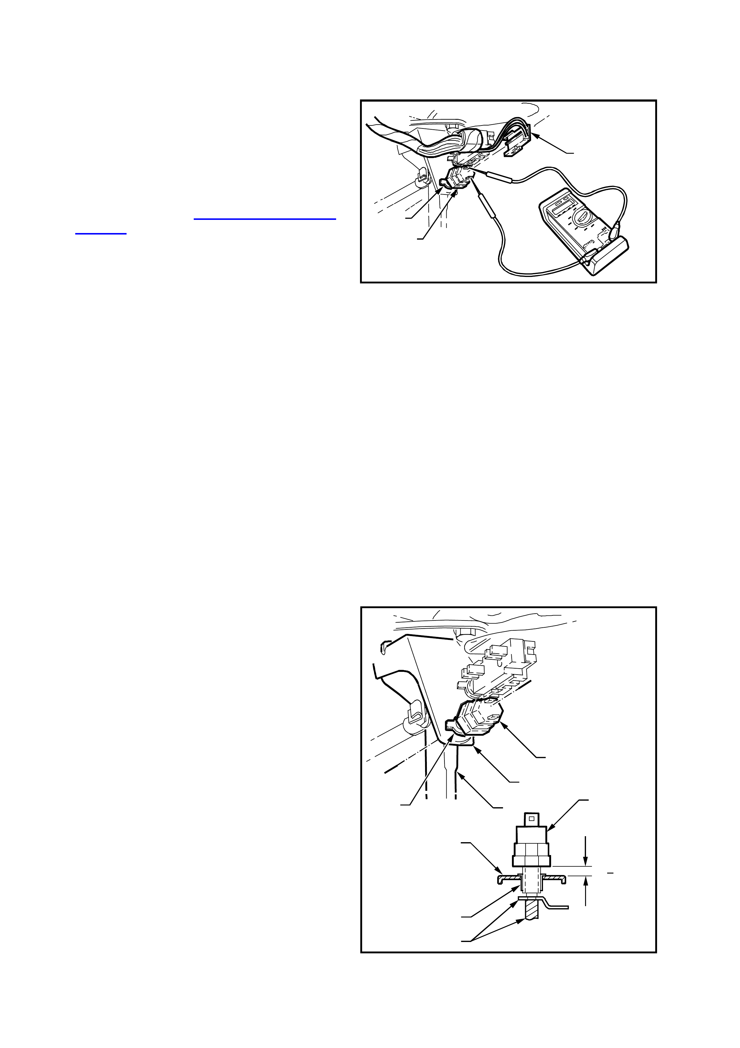
STEP ACTION VALUE YES NO
11. • Ignition ON.
• Back probe B CM c onnector YB175, term i nal , circuit 83
(Grey wire) with a voltmeter to earth.
• Repeatedly press the cruis e ON-OFF button again.
• Does the voltage vary as specified?
Switch
pressed:
approximately
12 Volts
Switch
released:
approximately
7 Volts
Go to CRUIS E
CONTROL
INTERFACE
DIAGNOSIS in
Secti on 12J-2
HIGH SERIES
BCM of the VT
Series II Service
Information.
Go to Step 12.
12. • Ignition OFF.
• Disconnect connec tor YE56 from crui se control module and
connect or Y B175 from B CM.
• Check f or continuit y bet ween connec tor YE56, terminal H
and connect or YB175, terminal 26, circuit 83 (Grey wire).
• Does continuity exist?
Replace crui se
control module
assembly, ref er to
2.2 CRUISE
CONTROL
MODULE in this
Section.
Repair open in
circui t 83, rechec k
and verify repair.
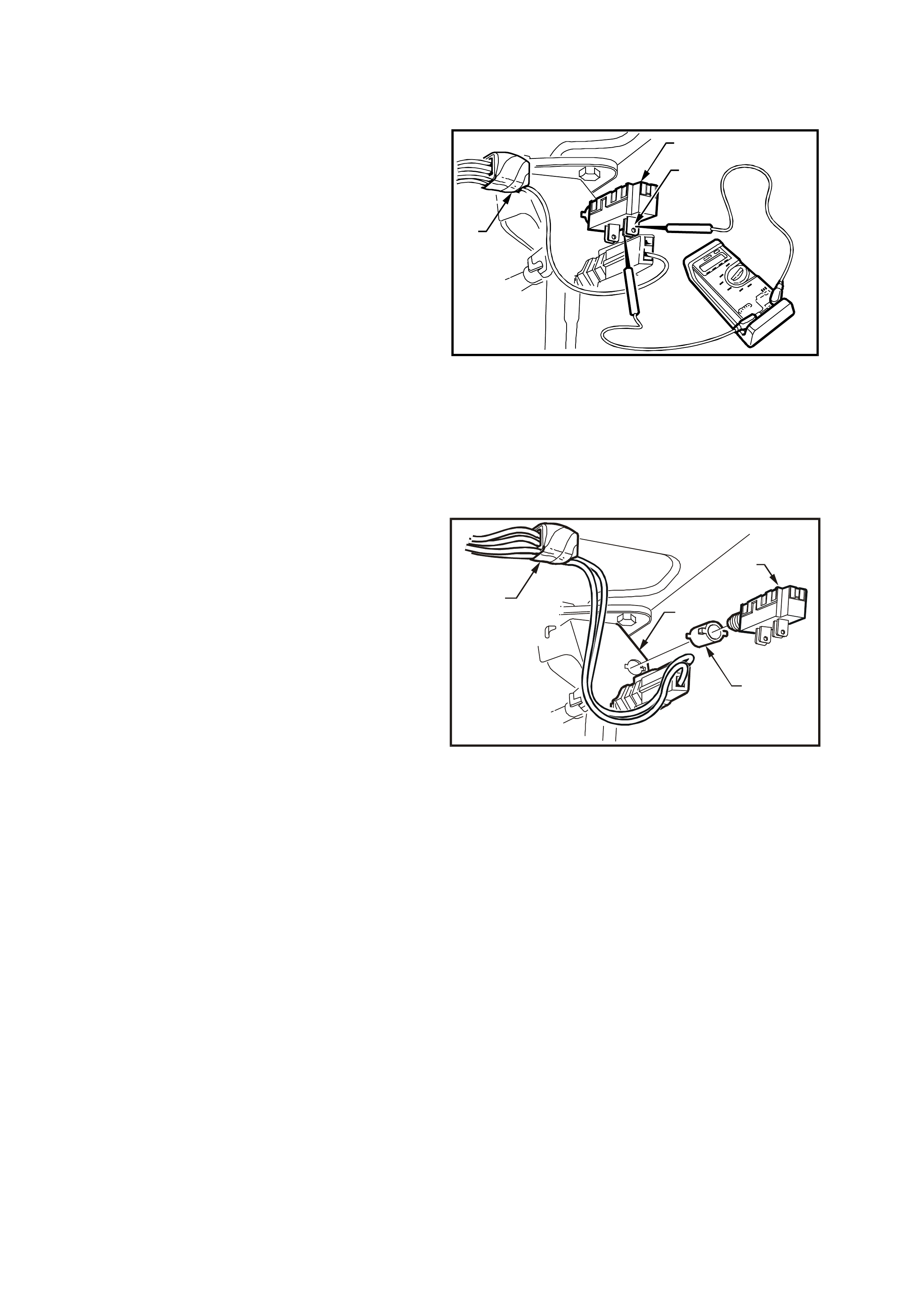
13. • Rem ove connector Y E 56 from c rui se control module.
• Ignition ON.
• Measure voltage at connector Y E 56, term i nal G, circui t 20
(Blue/Red wire) to eart h.
• Is voltage as spec i fied?
Less t han
1 Volt Go to Step 14. Check operat i on of
stop lamp switch
(switch A). In
particul ar, look for
improperl y adjusted
stop lamp switch.
Repair as
necess ary, recheck
and verify repair.
14. • Wit h c onnector YE56 s till disconnec t ed from c ruis e control
module and i gni tion ON, measure voltage at connector
YE56, terminal D, circ ui t 86 (Brown wire) to earth.
• Is voltage as spec i fied?
Approximately
12 Volts Go to Step 15. Check operat i on of
electri cal release
switch (switch B).
In particular, look
for improperly
adjusted switch or
check for open in
circui t 86. Repair
as neces sary,
recheck and veri fy
repair.
15. • Wit h c onnector YE56 s till disconnec t ed from c ruis e control
module and i gni tion ON (using an appropriate jumper l ead
from KM 609) place a short bet ween cruise control
connect or Y E56, terminal J and earth.
• Does the cruise control ACTIVE lamp illuminate in the
instrument c l uster?
Go to Step 17. Go to Step 16.
16. • Ignition OFF.
• Disconnect connector YB66 from instrum ent cluster.
• Check f or continuit y bet ween connec tor YE56, terminal J
and connect or Y B66, terminal 2, circuit 85 (White wire).
• Does continuity exist?
Check ACTIVE
lamp bulb, if OK,
replace ins trument
panel clus ter, refer
to Section 12C
INSTRUMENTS,
WIPERS /
W ASHERS &
HORN of the VT
Series II Service
Information.
Repair open in
circui t 85, rechec k
and verify repair.

CRUISE CONTROL SYSTEM DIAGNOSTIC CHART (Continued)
STEP ACTION VALUE YES NO
17. • Jack up rear of vehicle and s upport on safet y stands.
• Back probe cruise control connector YE56, t erminal K ,
circui t 123 (Violet /White) with a V ol tmet er to earth.
• Ignition ON.
• Spin rear wheels by hand.
• Does voltage vary as speci fied?
Varies f rom
less than 1 Volt
to greater than
10 Volts
Go to Step 18. Check f or open or
short t o eart h i n
circui t 123
(Violet/White wire)
between PCM and
cruise control
module connector
YE56, recheck and
verify repair
NOTE: If circuit 123
is OK, refer to PCM
diagnosis of the VT
Series I Servic e
Information. (for
V6), or PCM
diagnosis of the VT
Series II Service
Information. (for
GEN III V8)
18. • Connect all el ectrical connectors .
• Drive vehicle at approximately 50 k m/h and pres s the SET -
COAST butt on to set vehicle speed.
• Does the c rui se fail t o hol d speed?
Go to Step 19. System OK.
19. • Check c ondi tion and adjust ment of cruise control cable,
refer to 2. 1 CRUISE CONTROL CA BLE, in this Section.
• Is cabl e OK?
Go to Step 20. Adjust or replace
as neces sary the
cruise control
cable, refer to 2.1
CRUISE
CONTROL CABLE
in this Section.
20. • Perform switch di agnostic test, ref er to 3.3 SELF
DIAGNOSTIC TEST, SW ITCH DIAGNOSTIC TEST
CHART in t his Sec tion.
• Does tes t highlight a f aul t with the system?
Repair fault as
necess ary, recheck
and verify repair.
Replace crui se
control module
assembly, refer to
2.2 CRUISE
CONTROL
MODULE in this
Section.

4. TORQUE WRENCH SPECIFI CATIONS
Nm
Cable Mounting Bracket Securing Bolt................................. 6 – 14
Control Module Securing Screw ........................................... 2 – 5
Lever Stud Nut...................................................................... 1 – 3
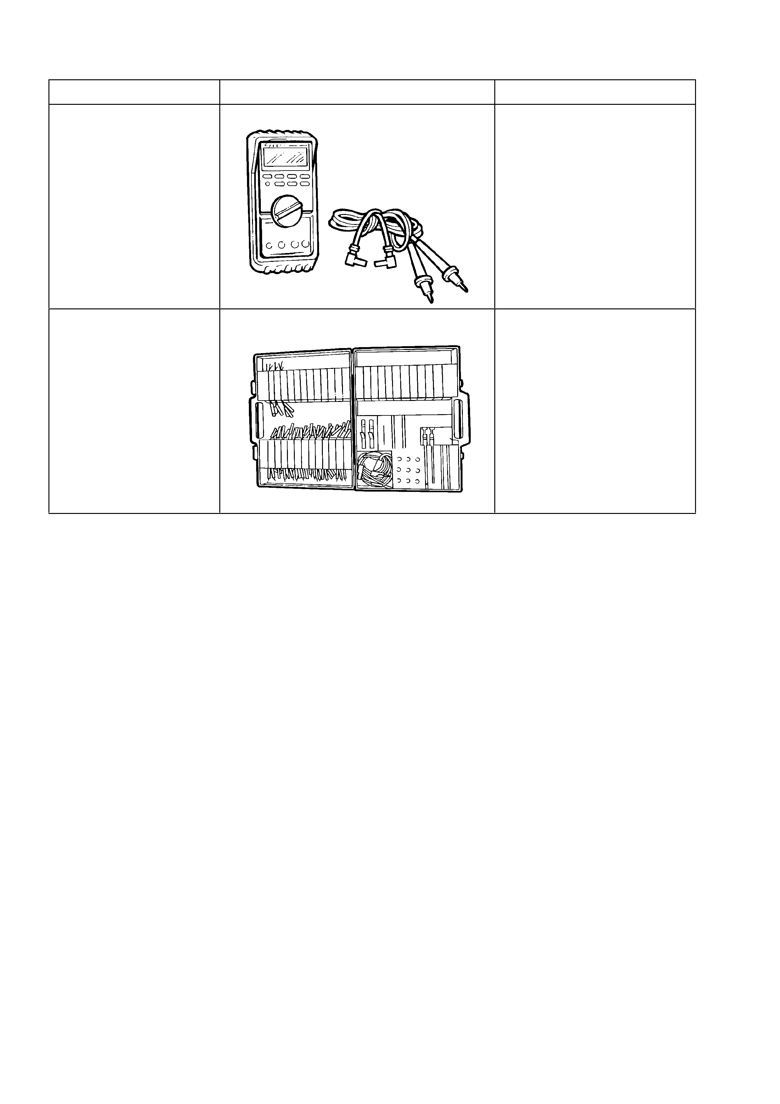
5. SPECIAL TOOLS
TOOL NO. REF IN TEXT TOOL DESCRIPTION COMMENTS
J39200 DIGITAL MULTIMETE R TOOL NO. J39200 PRE V IOUSLY
RELEASED, OR USE
COMMERCIALLY AVAILABLE
EQUIVALENT. MUST HAVE 10 MEG
OHM INPUT IMPEDANCE
KM-609 ELECTRONIC KIT USED IN CONJUNCTION WITH A
MULTIMETER FOR MEASURING
VOLTAGES AND RESISTANCES
WITHOUT DAMAGING WIRING
HARNESS CONNECTORS