SECTION 12G - CELLULAR MOBILE TELEPHONE
IMPORTANT
Before performing any Service Operation or other procedure described in this Section, refer to
Section 00 CAUTIONS AND NOTES for correct workshop practices with regard to safety and/or
property damage.
1. GENERAL I NFORMATI ON
The option of a cellular mobile telephone is available for WH Series Statesman and Caprice models. The antenna
coupling box assembly (internal) and antenna cable for the mobile phone are installed as standard fitment to these
vehicles, ready for the installation of a phone.
NOTE: The antenna mast and base assembly (external) are supplied as a kit with the vehicle, together with
installation instructions.
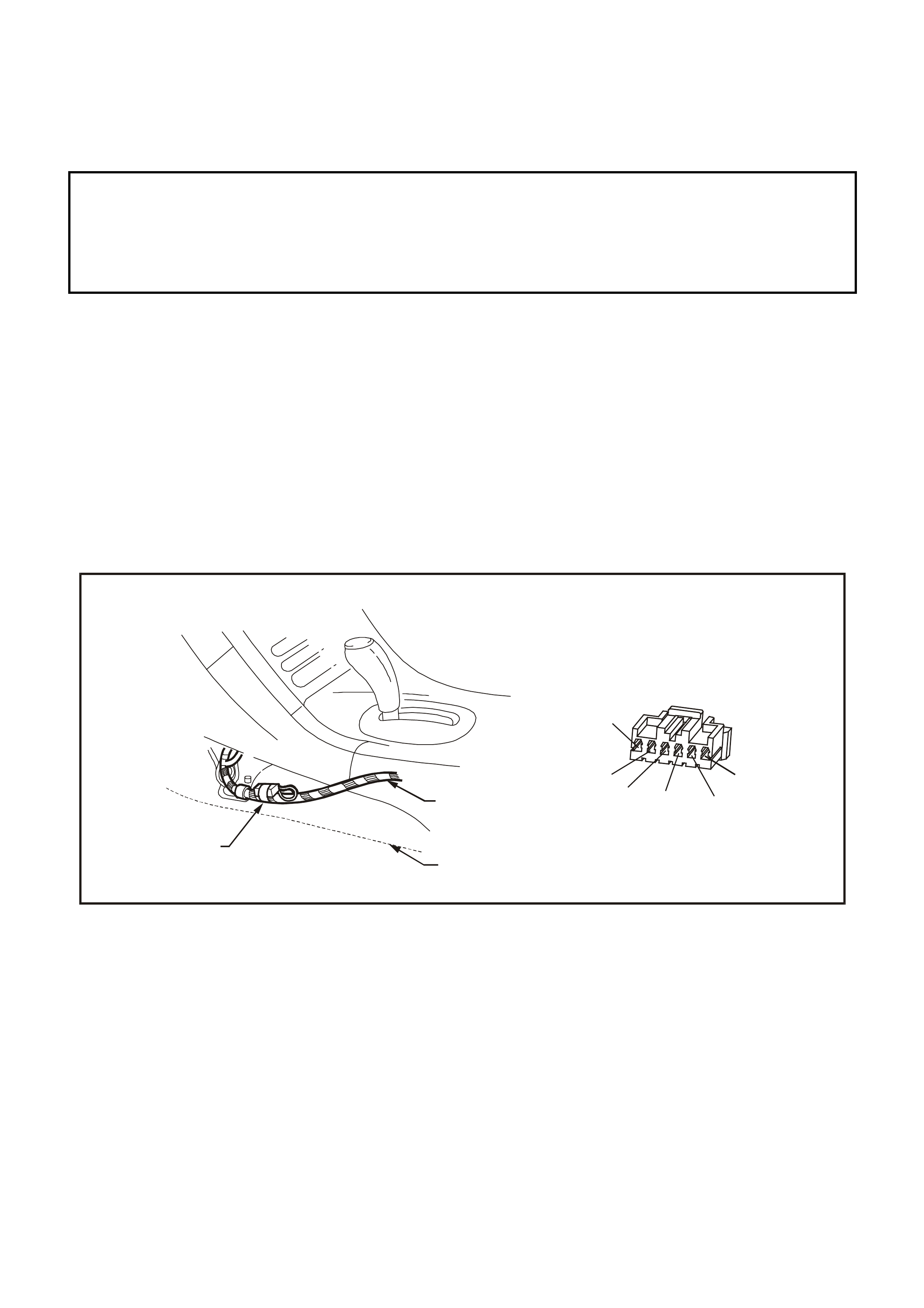
A connector for cellular telephone installation on WH Series vehicles is located under the centre console to the left
of the transmission gear shift lever. Wiring from this connector is connected into the back of the audio system to
enable audio system muting when the telephone is in use. The WH Series Statesman and Caprice are fitted with a
six-pin connector which enables a telephone with a hands-free kit to use the vehicle’s speakers and the radio
volume control for the telephone audio.
(45)
O/B
BLU/B
BLU/B
B/G
Y/B
Y
(659)
(665)
(151)
(656)
(43)
WH12G001a
2
13
Figure 12G-1
Connector
1. Cellular Mobile Telephone Connector O/B wire (45) – Battery Feed
2. Main Wiring Harness B/G wire (151) – Earth
3. Centre Facia Side Extension Panel Y wire (43) – Ignition Feed
Y/B wire (656) – Phone Mute Input
BLU/B wire (665) – Phone Signal
BLU wire (659) – Phone Signal Ground

2. SERVICE OPERATIONS
2.1 COUPLING BOX ASSEMBLY
REMOVAL
1. Unscrew the antenna lead connector from coupling box assembly.
2. Remove the antenna coupling box assembly by pulling the coupling box from the window. If necessary, use a
flat blade instrument (eg. spatula or scraper) to cut the adhesive securing the coupling box to the window.
3. Discard the coupling box.
REINSTALL
1. Wipe the wi ndow using Prepsol and ensure that all adhesive residue is removed.
2. Remove the paper backing from the new coupling box, align the coupling box with the guide marks on the
window, ensuring that the cable connector is positioned to the side indicated by the guide m arks and push the
coupling box firmly into position on the window .
3. Connect the antenna lead to the coupling box assembly.