
SECTION 12H - ELECTRICALLY ADJUSTABLE
REAR VISION MIRRORS
IMPORTANT
Before performing any Service Operation or other procedure described in this Section, refer to
Section 00 CAUTIONS AND NOTES for correct workshop practices with regard to safety and/or
property damage.
1. GENERAL I NFORMATI ON
Electrically adjustable exterior rear vision mirrors are fitted as standard equipment on all WH Series Models.
Each exterior mirror assembly has two internal reversible motors: one to adjust the mirror face up and down
(vertical position), the other to adjust the mirror face right and left (horizontal position).
The rear vision mirrors are adjusted from the interior of the vehicle by a mirror control switch mounted in the driver’s
side front door pull handle.
The control switch has two controls. A slide select switch that has two positions; left mirror and right mirror, and a
toggle type direction switch, which is used to control the direction of movement of the mirror face.
Additionally on Caprice Models, the exterior rear vision mirrors integrate with the memory seat and mirror system.
For additional and more comprehensive information regarding this feature, refer to Section 1A7 SEATS A ND SEAT
BELT ASSEMBLIES of the WH Service Information.
Statesman Models are fitted with a standard interior day / night mirror, while Caprice is fitted with an electro-
chromatic interior rear vision mirror, which when set to automatic, electronically changes the colour of the mirror
glass to reduce the reflection of headlamps from a following vehicle.
ELECTRO-CHROMATIC INTERIOR REAR VIEW MIRROR
An electro-chromatic interior rear vision mirror is fitted to all WH Caprice Models. The mirror features an
electronically controlled mirror cell which changes colour in response to an applied electrical voltage. This allows
automatic darkening of the mirror during night driving when headlamps from a following vehicle shine on an
integrated light sensor on the front of the mirror assembly. A second sensor is incorporated at the rear of the mirror
assembly w hich detects low ambient light (sun sensor). This second sensor ensures that this feature only works at
night time.
Incorporated on the bottom of the mirror assembly is an auto (on) / off switch. When the switch is switched from
auto to off, the mirror reverts to a standard ‘day driving’ mirror.
When the mirror is switched to the auto position and reverse gear is selected, the mirror will switch to the day
setting, regardless of the ambient light level.
2. SERVICE OPERATIONS
Service Operations for rear vision mirrors are to be found in various Sections of the VT Series Service Information
and this Supplement as per the following table:
VEHICLE COMPONENT PROCEDURE REFER
Statesman Interior rear vision mirror All Section 1A6 STATIONARY
GLASS of the WH Service
Information.
Exterior rear vision mirror All 12H ELECTRICALLY
ADJUSTABLE REAR
VISION MIRRORS of the VT
Series I Service Information.
Caprice Electro-chromatic interior
rear vision mirror All This Section.
Exterior rear vision mirror Assembly removal,
reinstallation and test. 12H ELECTRICALLY
ADJUSTABLE REAR
VISION MIRRORS of the VT
Series I Service Information.
Mirror glass removal and
reinstallation.
Mirror control switch
removal, reinstallation and
test.
Mirror switch module
removal, reinstallation and
diagnosis.
Section 1A7 SEAT & SEAT
BELT ASSEMBLIES of the
WH Service Information.
Memory seat and mirror
assembly diagnosis.
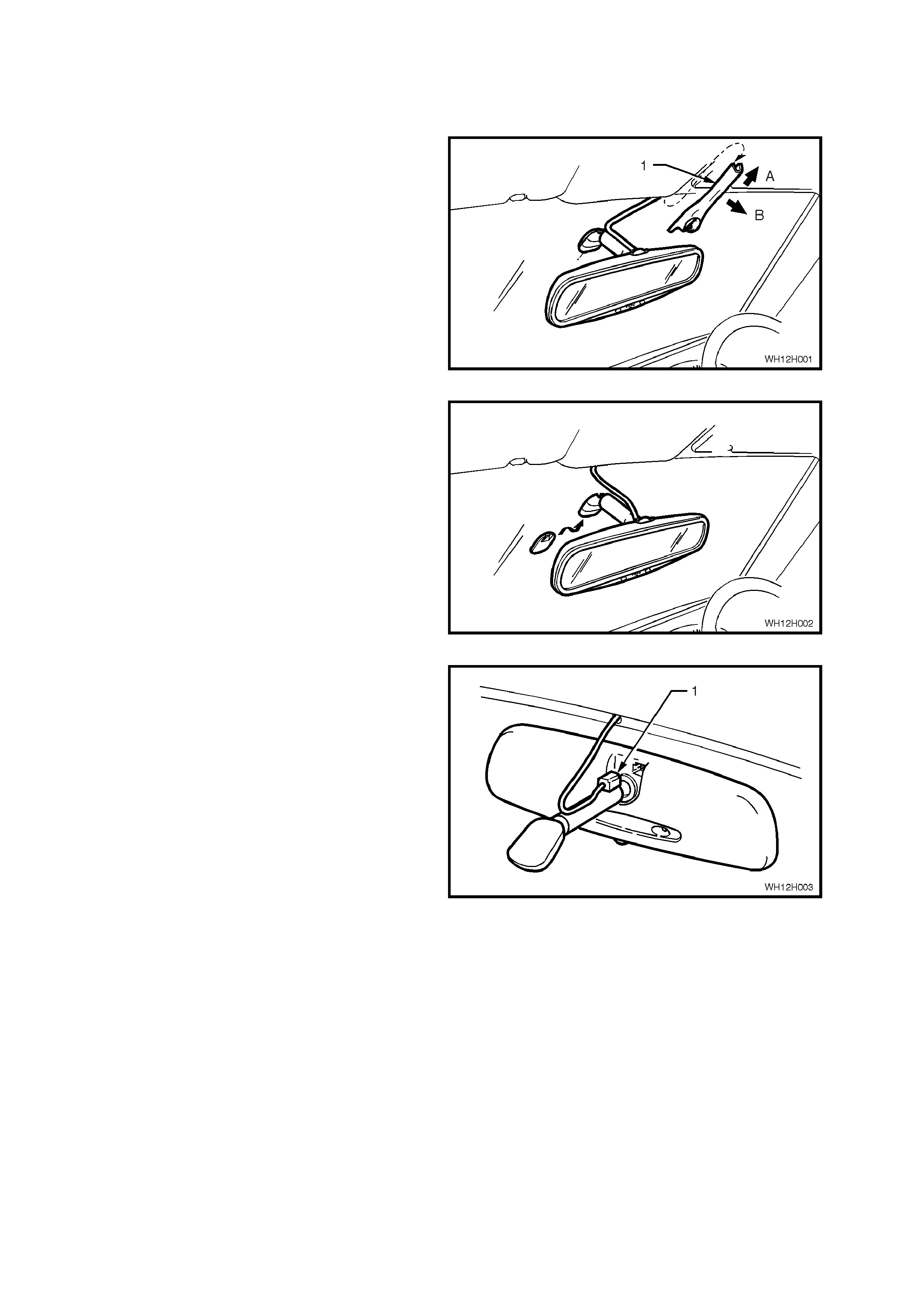
2.1 ELECTRO-CHROMATIC INTERIOR REAR VISION MIRROR
REMOVE
1. Remove mirror wiring harness cover (1) by
sliding cover upwards slightly (direction A) and
pull cover downwards (direction B).
Figure 12H-1
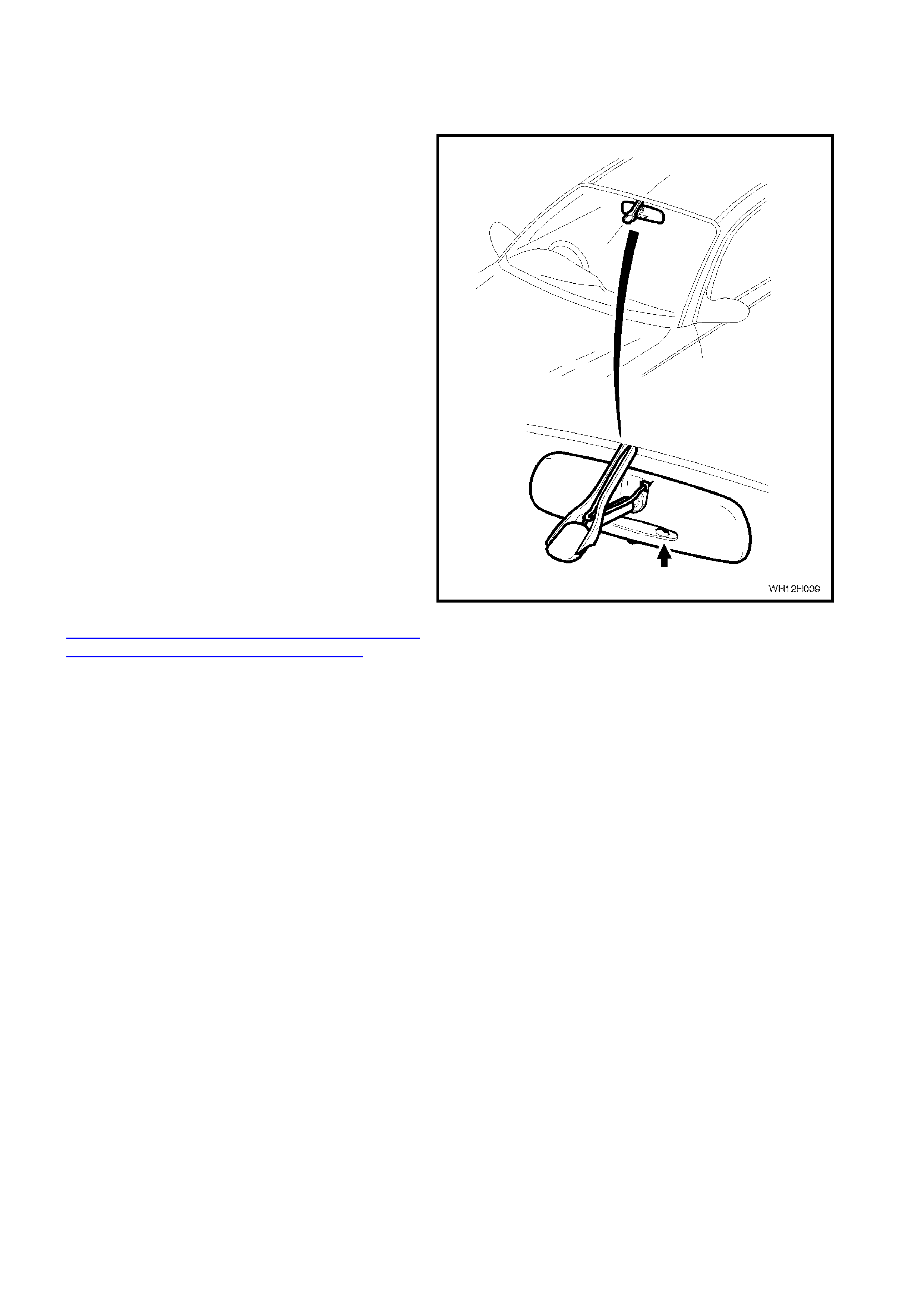
2. Disengage the interior mirror from the boss on
the windscreen by sliding the base of the mirror
upwards.
Figure 12H-2
3. Disconnect the interior mirror wiring harness
connector and remove the mirror.
Figure 12H-3
REINSTALL
Reinstallation of the interior rear view mirror is the
reverse of the removal procedure, noting the
following:
When installing the mirror onto the boss on the
windscreen, ensur e that it is pushed down fully and
clicks into position.
3. ELECTRO-CHROMATIC I NTERI OR REAR VISION MI RROR DIAGNOSIS
3.1 FUNCTIONAL CHECK
The f ollowing procedure should be used to c heck if
the electro-chromatic interior rear vision mirror is
functioning correctly.
1. With mirror installed, cover the ambient light
sensor at the rear of the mirror (forward facing),
using a piece of black electrical tape.
2. Turn ignition switch to ‘ON’ position.
3. Turn mirror switch to ‘AUTO’ position.
4. Observe that ‘GREEN’ LED in mirror is
illuminated.
5. Shine a beam of light (torch) into the front light
sensor (rearward facing) and ensure that the
mirror darkens.
NOTE: The f ront light sensor is located adj acent to
the green LED, to the left of the auto / off switch.
6. With ignition on, select reverse gear, mirror
should return to full reflectance (5 - 10
seconds).
7. Repeat Step 5, then turn ignition off (LED off)
Turn ignition switch to ‘OFF’ position, mirror
should again return to full reflectance (5 - 10
seconds).
NOTE: If the mirror does not function according to
the above, rem ove the m irror, as per the proc edure
detailed in this Section and proceed to the
3.3 ELECTRO-CHROMATIC INTERIOR REAR
VISION MIRROR DIAGNOSTIC CHART in this
Section.
Figure 12H-4
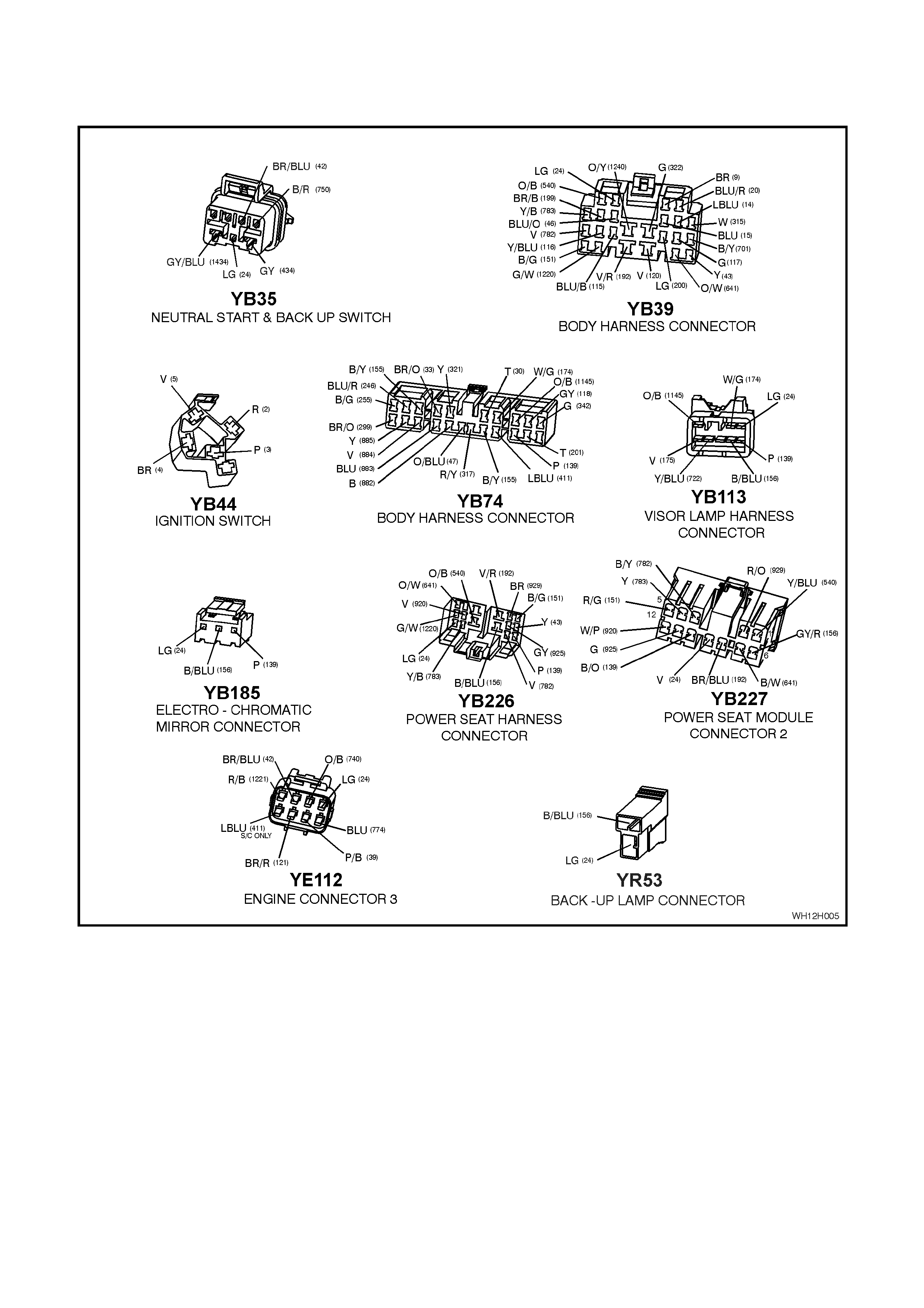
3.2 ELECTRO-CHROMATIC INTERIOR REAR VISION MIRROR CIRCUIT DIAGRAM &
CONNECTORS
Figure 12H-5
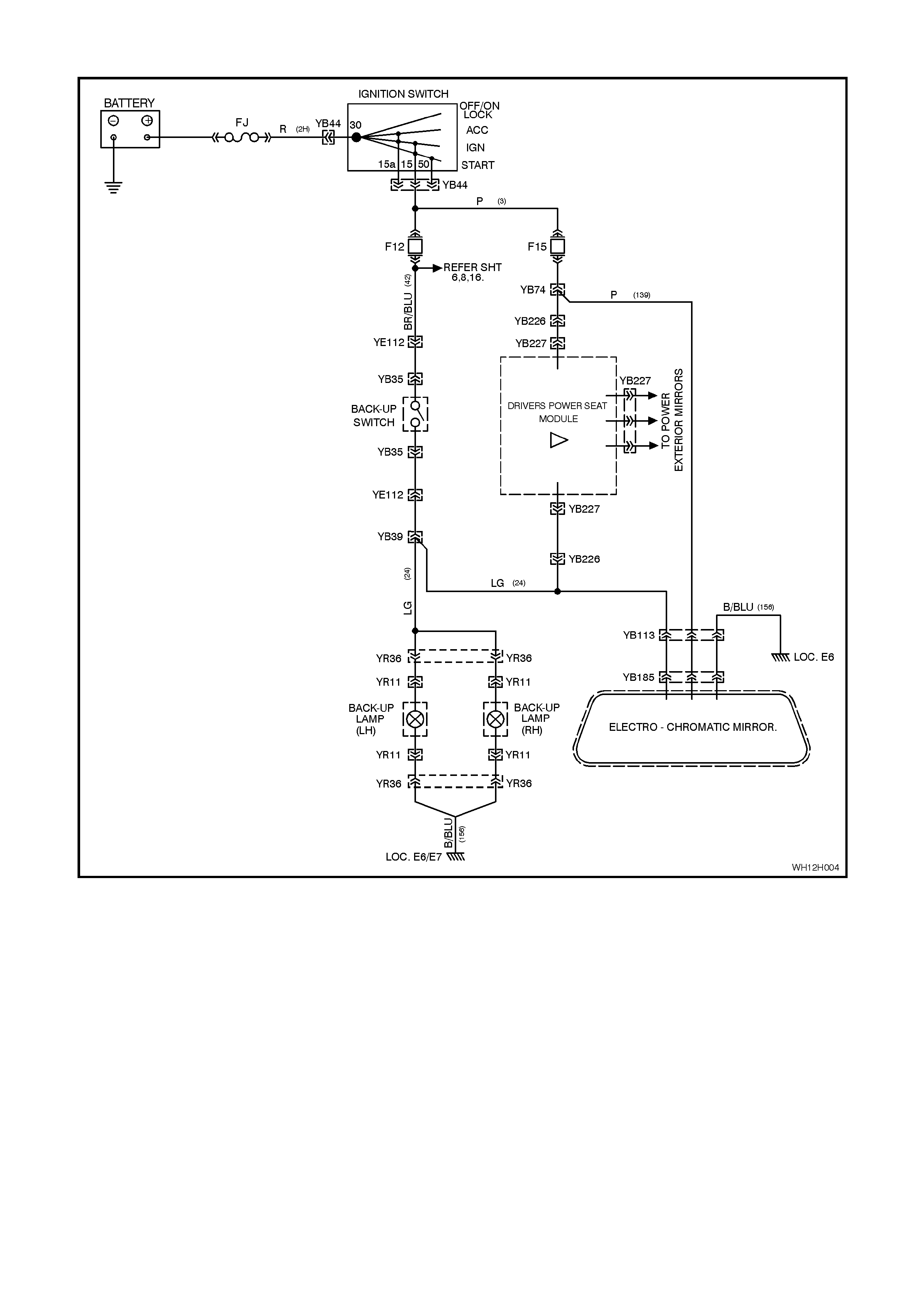
Figure 12H-6

3.3 ELECTRO-CHROMATIC INTERIOR REAR VISION MIRROR DIAGNOS TIC CHART
Test Description
The numbers below refer to Step numbers in the diagnostic chart for the electro-chromatic interior rear vision
mirror.
1. Ensures the Functional Check has been performed.
2. Determines if the functionality of mirror is correct.
3. Determines if the functionality of mirror is correct.
4. Checks circuits 139 and 156 for power and earth at connector YB185.
5. Checks circuit 139 for open or short to earth.
6. Checks circuit 156 for open.
7. Checks earth connection at earth location E6.
8. Checks integrity of back-up lamp circuits 24 and 42 (including operation of back-up lamp switch.
Notes on Diagnostic chart:
1. Refer to Section 12P WIRING DIAGRAMS of the VT Series I Service Information for procedures on checking
wiring faults.

STEP ACTION VALUE YES NO
1. • Has the electro-chromatic interior rear vision mirror
Functional Check been performed? Go to Step 2. Go to 3.1
FUNCTIONAL
CHECK in this
Section.
2. • In Step 5 of the Functional Check, did mirror change
colour (darken)? Go to Step 3. Go to Step 4.
3. • In Step 6 of the Functional Check, did mirror return
to full reflectance when reverse gear was selected? Mirror OK Go to Step 8.
4. • Remove electro-chromatic interior rear vision mirror,
refer 2.1 ELECTRO-CHROMATIC INTERIOR REAR
VISION MIRROR in this Section.
• Disconnect electro-chromatic interior rear vision
mirror connector YB185.
• Measure voltage between connector YB185 circuit
139 (Pink wire) and circuit 156 (Black/Blue wire)
(refer NOTE 1).
• Turn ignition ON.
• Is voltage as specified?
Battery + Go to Step 5. Replace electro-
chromatic interior
rear vision mirror
assembly, refer
2.1 ELECTRO-
CHROMATIC
INTERIOR REAR
VISION MIRROR
in this Section.
5. • With connector YB185 disconnected, measure
voltage between connector YB185 circuit 139 (Pink
wire) and a known good earth (refer NOTE 1).
• Turn ignition ON.
• Is voltage as specified?
Battery + Go to Step 6. Repair open or
short to earth in
circuit 139 as
necessary
(including fuse
F15). Recheck
and verify repair.
6. • Turn ignition OFF.
• With connector YB185 disconnected, check for
continuity between connector YB185, circuit 156
(Black/Blue wire) and earth at location E6 (body
harness earth to transmission tunnel) (refer NOTE
1).
• Does continuity exist?
Go to Step 7. Repair open in
circuit 156 as
necessary.
Recheck and
verify repair.
7. • Turn ignition OFF.
• Check for continuity between earth location E6 and
a known good earth (refer NOTE 1)?
• Does continuity exist?
Replace electro-
chromatic interior
rear vision mirror
assembly, refer
2.1 ELECTRO-
CHROMATIC
INTERIOR REAR
VISION MIRROR
in this Section.
Repair earth as
necessary.
Recheck and
verify repair.
8. • Remove electro-chromatic interior rear vision mirror,
refer 2.1 ELECTRO-CHROMATIC INTERIOR REAR
VISION MIRROR in this Section.
• Disconnect electro-chromatic interior rear vision
mirror connector YB185.
• Measure voltage between connector YB185 circuit
24 (Light Green wire) and a known good earth (refer
NOTE 1).
• Turn ignition ON.
• Select reverse gear.
• Does voltage change from 0 volts to battery + volts
when reverse gear is selected?
Replace electro-
chromatic interior
rear vision mirror
assembly, refer
2.1 ELECTRO-
CHROMATIC
INTERIOR REAR
VISION MIRROR
in this Section.
Repair back-up
lamp circuits 24
and 42 as
necessary
(including
operation of
back-up lamp
switch, refer to
Section 12B
LIGHTING
SYSTEM of the
WH Service
Information).
Recheck and
verify repair.