
SECTION 12J-2 - HIGH SERIES BODY
CONTROL MODULE
IMPORTANT
Before performing any Service Operation or other procedure described in this Section, refer to
Section 00 CAUTIONS AND NOTES for correct workshop practices with regard to safety and/or
property damage.
1. GENERAL DESCRI PTI O N
The Body Control Module (BCM) fitted to all WH Series Statesman and Caprice Models is the same BCM as fitted
to the VT Series II Calais; a High (HI) Series BCM.
For all BCM information, including General Description, Service Operations, TECH 2 Diagnosis, Diagnosis and
Special Tools for WH Series Models, refer to Section 12J-2 HIGH SERIES BODY CONTROL MODULE of the VT
Series II Service Information, noting the following.
• The BCM information compiled in the VT Series II Information addresses new features and changes to VT
Series II BCM, and as such, is to be read in conjunction with Section 12J-2 HIGH SERIES BODY CONTROL
MODULE of the VT Series I Service Information.
• When using TECH 2 on a WH Series Model, ensure the correct Model Year and Vehicle Type is selected:
(X) 1999 WH Statesman & Caprice.
• With the introduction of memory adjustable electric driver’s seat and external rear view mirrors, on WH Caprice,
come changes to the priority key system. As a result of these changes, the priority key system General
Information and diagnostic procedure has been modified and republished in full in this Section.
Also, with changes to the priority output lines, there are some minor changes to terminal assignments on the
BCM connectors. As a result of this, the BCM connector / terminal assignment and identification information
has been updated for WH and re-published in full in this General Description Section.
• When diagnosing any circuit fault relating to the BCM on a WH Series Model, reference to the wiring diagrams
in Section 12P WIRING DIA GRAMS of this Service Information Supplement should be made.
Techline
Techline
Techline
Techline
Techline
Techline
Techline
Techline
Techline

HIGH SERIES BCM TERMINAL IDENTIFICATION
YB176 CONNECTOR 4
PIN NO. DESCRIPTION CIRCUIT WIRE COLOUR CIRCUIT TYPE
A1 EARTH (ELECTRONIC) 155 B/Y E
A2 INSTRUMENT ILLUMINATION OUTPUT 8 GY O
A3 THEFT DETERRENT HORN OUTPUT 1128 B/W O
A4 HORN OUTPUT 28 B/Y 0
A5 BATTERY POSITIVE 740 O/B P
A6 THEFT DETERRENT LED OUTPUT 263 LBLU O
A7 INTERIOR ILLUMINATION OUTPUT 1138 W O
A8 REAR WIPER OUTPUT 492 GY/BLU O
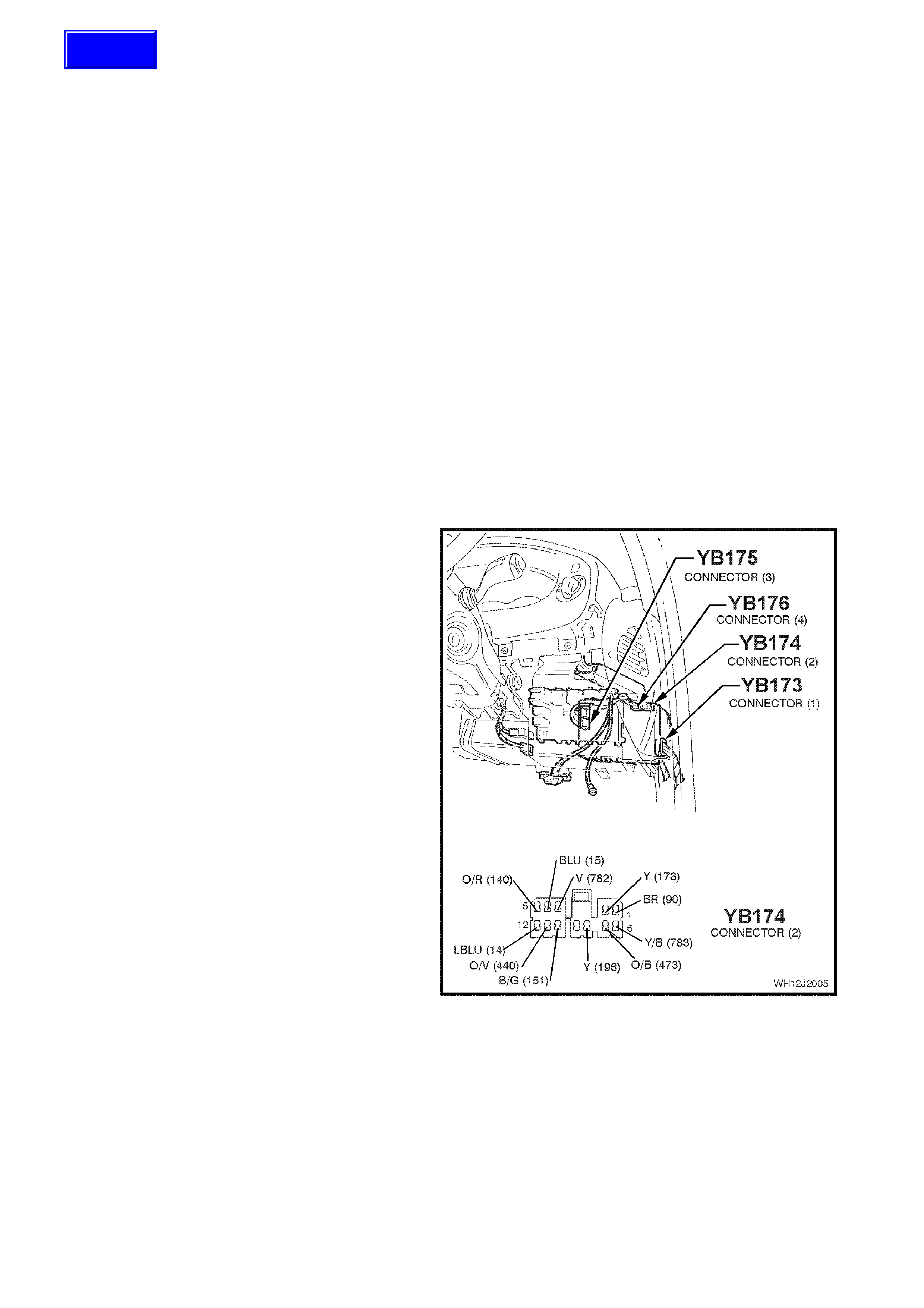
YB174 CONNECTOR 2
PIN NO. DESCRIPTION CIRCUIT WIRE COLOUR CIRCUIT TYPE
B1 WIPER OUTPUT 90 BR O
B2 POWER WINDOW OUTPUT 173 Y O
B3 PRIORITY KEY ONE OUTPUT 782 V O
B4 RIGHT INDICATOR OUTPUT 15 BLU O
B5 INDICATOR POWER 140 O/R P
B6 PRIORITY KEY TWO OUTPUT (Caprice only) 783 Y/B
B7 LOW FAN SPEED OUTPUT 473 O/B O
B8 WIPER PARK INPUT 196 Y PD/O
B9 NC
B10 POWER EARTH 151 B/G E
B11 DOOR LOCK POWER 440 O/V P
B12 LEFT INDICATOR OUTPUT 14 LBLU O
YB173 CONNECTOR 1
PIN NO. DESCRIPTION CIRCUIT WIRE COLOUR CIRCUIT TYPE
C1 WINDOW POWER INPUT 1240 O/Y P
C2 WI NDOW MOTOR OUTPUT 673 G/O O
C3 DRIVERS DOOR UNLOCK OUTPUT 293 BLU/B O
C4 ANTENNA DRIVE OUTPUT 145 G O
C5 DOME ON INPUT 175 V PD
C6 BOOT LAMP INPUT 232 Y/G PPU
C7 PASSENGER DOOR AJAR INPUT 125 W PPU
C8 DRIVERS DOOR AJAR INPUT 126 GY/W PPU
C9 PASSENGERS DOOR UNLOCK INPUT 194 BR/O PU
C10 NC
C11 NC
C12 DEADLOCK OUTPUT 394 V/W O
C13 ALL DOORS, LOCK OUTPUT 295 B/Y O
C14 WINDOW DOWN INPUT 167 G/B PD
C15 STOP/TAIL SENSE INPUT 1251 BR/W I
C16 WINDOW UP INPUT 672 BLU/W PD
C17 ANTENNA DIRECTION OUTPUT 954 GY O
C18 NC
C19 DOME - DOOR INPUT 722 Y/BLU PD
C20 UNLOCK INPUT 193 LG/Y PPU
C21 LOCK INPUT 195 BR/R PPU
C22 DEADLOCK REQUEST INPUT 197 BR/W PPU
C23 NC
C24 DOME LAMP OUTPUT 174 W/G O
C25 BOOT OUTPUT 142 R/G O
C26 PASSENGER DOOR UNLOCK OUTPUT 294 B/R O

YB175 CONNECTOR 3
PIN NO. DESCRIPTION CIRCUIT WIRE COLOUR CIRCUIT TYPE
E1 SLIP RING 229 V/R I/O
E2 SERIAL DATA INTERFACE MAIN BUS 1221 R/B I/O
E3 AIRBAG SERIAL DATA INTERFACE BUS 1220 W/G I/O
E4 POWER STEERING SOLENOID OUTPUT 558 B/Y O
E5 WIPER DWELL INPUT 96 GY/B PU
E6 NC
E7 RECEIVER EARTH 271 BR/G E
E8 RECEIVER DATA 266 Y I
E9 SERIAL DATA INTERFACE AUXILIARY BUS 1220 G/W I/O
E10 TWILIGHT INPUT (AMBIENT LIGHT SENSOR) 272 Y/B I
E11 INSTRUMENT DIMMER INPUT 717 W PU
E12 AUTO LIGHTS EARTH OUTPUT 308 W/R O
E13 ANTENNA DOWN INPUT 160 W PPU
E14 ANTENNA UP INPUT 161 LBLU PPU
E15 REAR WASHER INPUT 494 W/BLU PD
E16 RADIO ON INPUT 143 Y/R PD
E17 ACCESSORIES INPUT 43 Y PD, P
E18 STOP LAMP FUSE INPUT 640 O/BLU PD
E19 REAR WIPER INPUT 1391 GY/R PD
E20 IGNITION INPUT 39 P/B PD, P
E21 BONNET SWITCH INPUT 261 R/W PPU
E22 BOOT RELEASE INPUT 1144 B/R PPU
E23 BONNET SWITCH INPUT 260 Y/B PD
E24 PARK LAMP FUSE INPUT 840 O/W PD
E25 FRONT SCREEN WASH/WIPE INPUT 94 LBLU PU
E26 CRUISE CONTROL ON INPUT 83 GY PD
E27 FRONT INTERMITTENT AUTO WIPE INPUT 97 BLU/W PD
E28 LIGHTS OFF EARTH OUTPUT 1150 B O
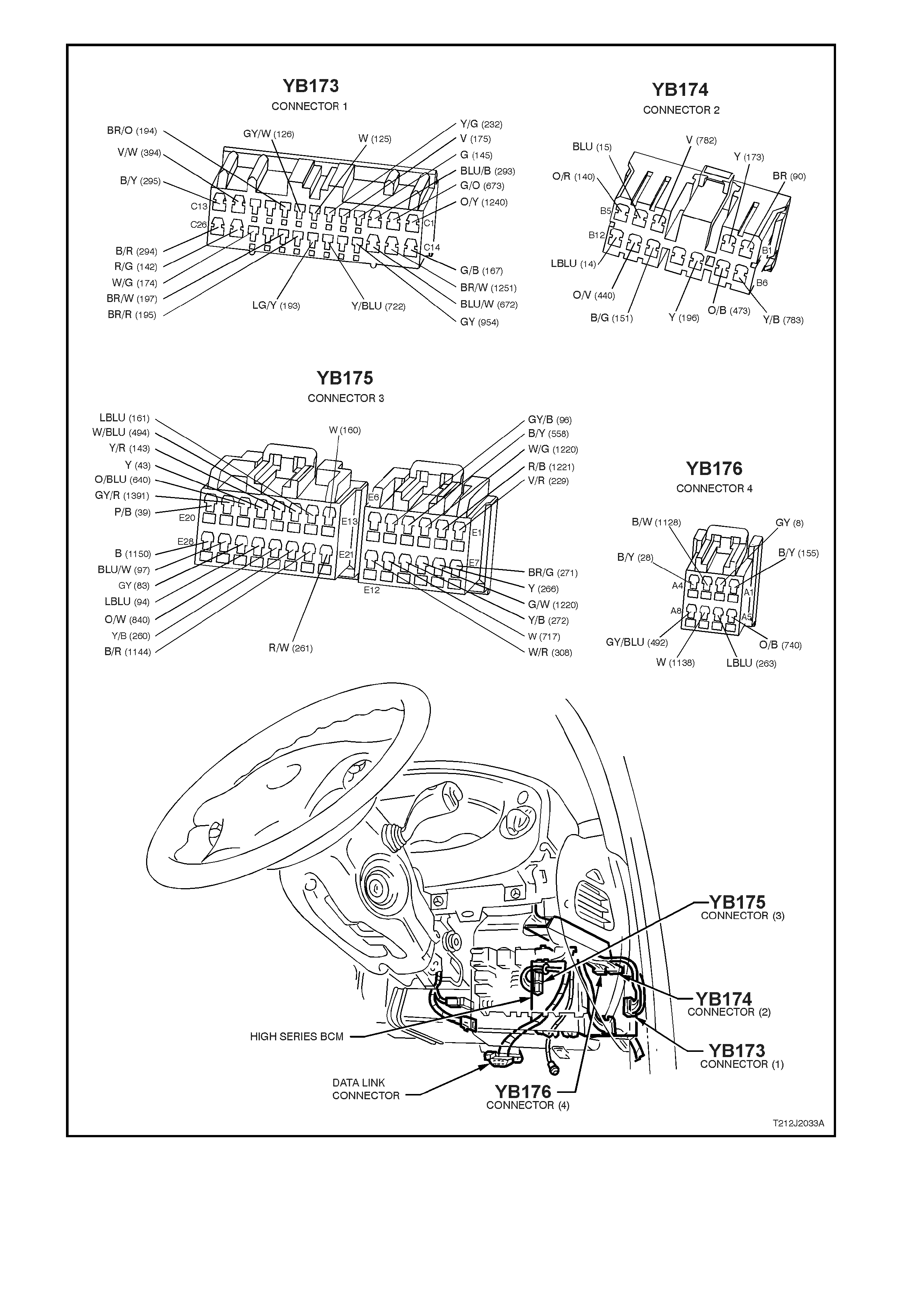
Figure 12J-2-1 BCM location and connector / terminal assignment

1.1 PRIORITY KEY SYSTEM
GENERAL INFORMATION
The BCM provides the ability to remember two sets of system operating parameters. These operating parameters
are recalled when a specific remote key is used. When a priority one remote coded key is used, the BCM will recall
the operating parameters related to the priority one key. When a priority two key is used, the BCM will recall the
operating parameters related to the priority two key.
The operating parameters recalled are for the following functions:
• Time delay for automatic headlamps off.
• Antenna height memory.
• Instrument dimmer level.
These operating parameters are recalled when the UNLOCK button on the remote key is pressed or when the
ignition is turned to the ACC position, all operating parameters are maintained on a last used basis.
The BCM also communicates to other modules via the serial data bus, identifying which priority mode (priority one
or priority two) each module should be in.
The following modules will use the serial data bus priority information:
• Trip computer, mode and overspeed setting.
• Electronic Climate Control, all settings.
• Power / Economy switch position.
NOTE: Communication between the PCM and the BCM on vehicles with GEN III V8 engines is via the Powertrain
Interface Module (PIM).
In addition, the BCM also includes two priority output lines; priority one output line and priority two output line.
The priority one output line sets the radio’s priority mode. When this output is low, the radio settings are set for
priority one. When this output is high, the radio settings are set for priority two.
On WH Caprice, the priority one output line is also used, in conjunction with the priority two output line, for setting
the memory adjustable driver’s seat and external rear view mirrors.
Two priority lines are required for this feature due to the electrically adjustable seats being able to operate when the
ignition is switched off and the fact that when the ignition is switched off, both priority one and priority two output
lines default to high (12 volts).
If only one priority line was used for this feature, each time the ignition was switched off, the seat would
automatically move to priority two mode due to the priority lines defaulting to high.
Priority one output line LOW
Priority two output line HIGH
Memory adjustable driver’s seat and external rear
view mirrors in priority one mode.
Priority one output line HIGH
Priority two output line LOW
Memory adjustable driver’s seat and external rear
view mirrors in priority two mode.
Priority one output line HIGH
Priority two output line HIGH
(Ignition switch off default)
Memory adjustable driver’s seat and external rear
view mirrors in neutral (no automatic movement)
NOTE: Due to safety concerns, the memory adjustable driver’s seat, and consequently, the external rear view
mirrors will only change between priority one and priority two modes when the unlock button on the remote coded
key is pressed and the ignition is off.
When a new remote key is programmed, it is assigned as the priority one key. All remaining remote keys become
priority two keys. Any remote key can be assigned as the priority one key using TECH 2, all other keys will then
become priority two keys.
NOTE: The circuit diagrams shown in this General Information Section are to aid in interpreting the operation of the
circuit and therefore, only the main connectors and wiring colours are shown. For complete circuit details, refer to
either the relevant diagnostic section in this Service Information CD or Section 12P - WIRING DIAGRAMS of this
Service Supplement.

CIRCUIT OPERATION
(Refer to Fig. 12J-2-2)
When the UNLOCK button on the remote key is activated or the ignition is switched on, the BCM will send serial
data via the serial data interface auxiliary bus to the trip computer, ECC module and PCM (PCM via PIM on vehicles
with GEN III V8 engine). Depending on which remote key was activated (priority one or priority two), the BCM will
identify via this serial data, which mode each module should be in.
Priority Key Mode
(Refer To Figs. 12J-2-2)
The priority one output line (BCM terminal B3, circuit 782) sets the radio’s priority mode. When the voltage on this
output is pulled low (unlock button on the remote coded key pressed or ignition on), the radio settings are set for
priority one. When the voltage on this output is high, the radio settings are set for priority two.
On WH Caprice, the priority one output line, in conjunction with the priority two output line (BCM terminal B6, circuit
783) also set the memory adjustable drivers seat and external rear vision mirrors.
When voltage on the priority one output line is pulled low, (unlock button on the remote coded key pressed) and the
voltage on the priority two output line is high, the memory adjustable drivers seat and external rear vision mirrors
are set for priority one mode.
When voltage on the priority one output line is high and the voltage on the priority two output line is pulled low, the
memory adjustable drivers seat and external rear vision mirrors are set for priority two mode.
When the ignition is switched off, the voltage on both the priority one and two output lines default to 12 volts. When
either the unlock button on the remote coded key is pressed or the ignition is switched on, either the priority one or
priority two (depending on which key is used) output line is pulled low for one second.
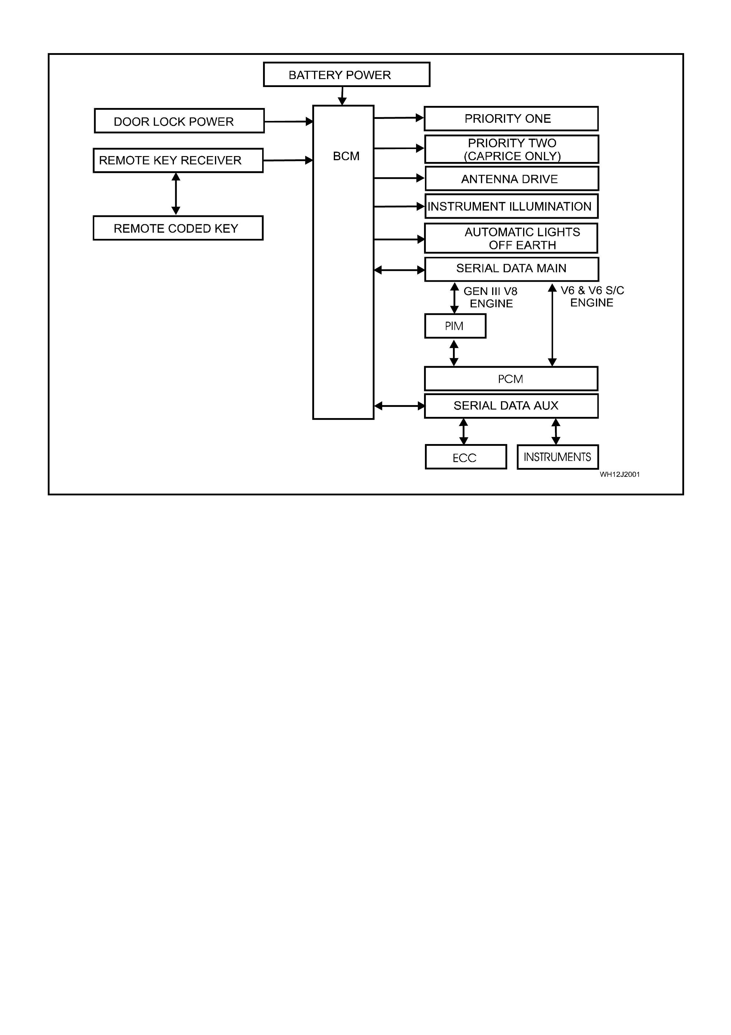
SYSTEM OVERVIEW
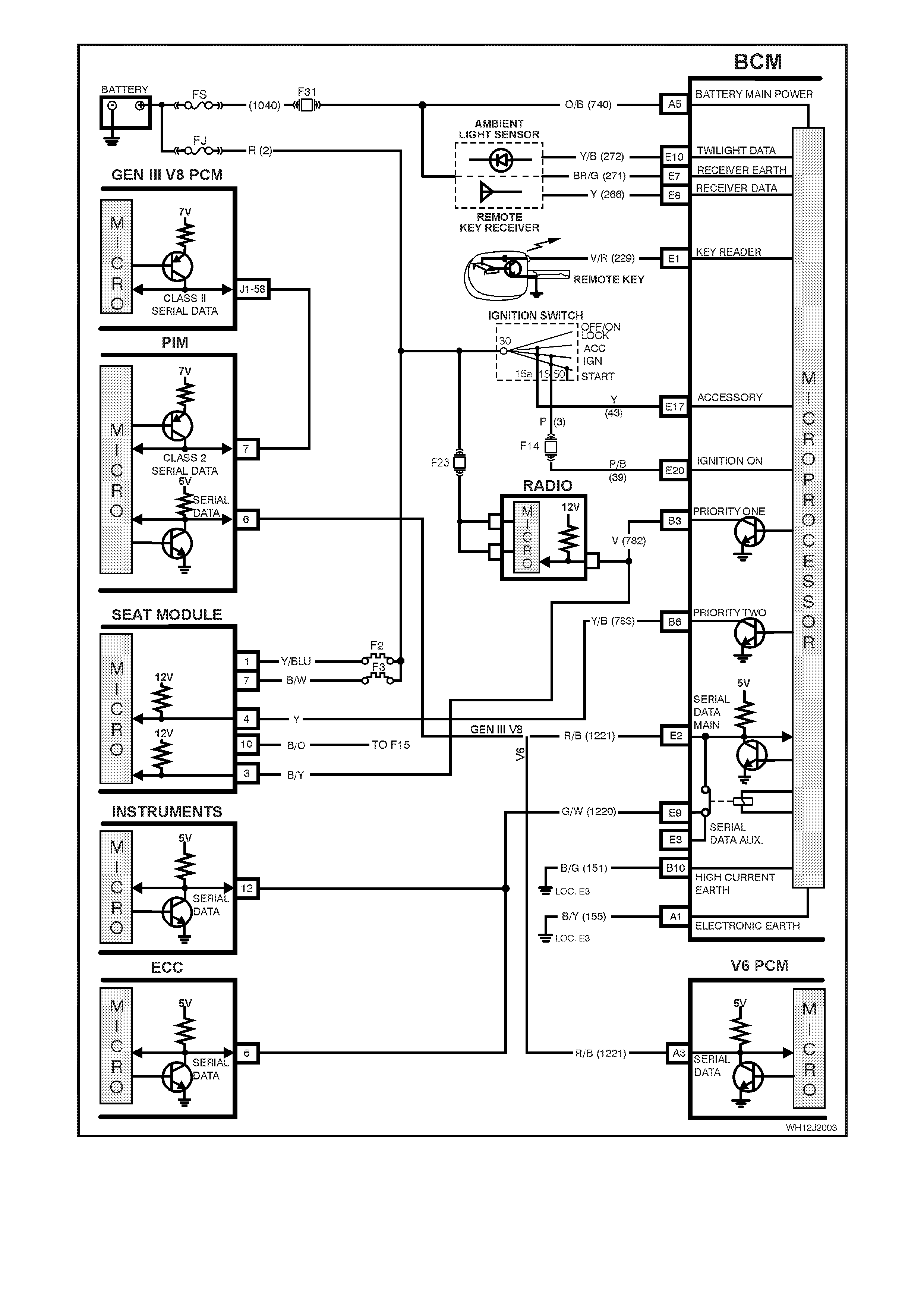
Figure 12J-2-2
2. DIAGNOSIS
2.1 PRIORITY KEY SYSTEM
CIRCUIT DESCRIPTION
The BCM provides an additional mem ory for one of
the remote keys (priority one). The normal priority
memory (priority two) is used for all other keys.
The BCM stores two separate sets of parameters,
one for each key for the following functions:
• Time delay for automatic headlights off.
• Antenna height memory.
• Instrument dimmer level.
These memories are recalled when the unlock
button on the remote coded key is pressed and all
memories are maintained on a last used basis.
The BCM also communicates to other modules
(ECC, instrument modules) via the auxiliary serial
data bus (circ uit 1220), identifying which priority key
mode (priority one or two) each module should be
in.
In addition, the BCM also includes two priority
output lines (priority one, circuit 782 and priority
two, circuit 783).
The priority one output line sets the radio’s priority
mode. When the prior ity one output is pulled low for
one second, the radio settings are set for priority
key one.
On WH Caprice, the priority one output line, in
conjunction with the prior ity two out put line also set
the memory adjustable driver’s seat and external
rear vision mirrors.
When voltage on the priority one output line is
pulled low for one second and the voltage on the
priority two output line is high, the memory
adjustable driver’s seat and external rear vision
mirrors are set for priority one mode.
W hen voltage on the priority one output line is high
and the voltage on the priority two output line is low
for one second, the memory adjustable driver’s
seat and external rear vision mirrors are set for
priority two mode.
When the ignition is switched off, the voltage on
both the priority one and two output lines default to
12 volts.
NOTE: The memory adjustable electric seat and
external rear view mirrors will only change status
between priority one and priority two when the
unlock button on the remote coded key is pressed
and the ignition is switched off. Figure 12J-2-3
Techline

Test Description
The numbers below refer to step numbers in the
following diagnostic chart.
1-6.Functional check of priority key system.
7. Additional functional check of the priority
system for Caprice.
8. Uses TECH 2 to check if BCM is
communicating with the instruments to
determine if fault is with instrument cluster or if
there is a serial data communication fault.
9. Checks priority one output from the BCM.
10. Checks integrity (open, short) of circuit 782.
11. Uses TECH 2 to check priority state of remote
keys.
12. Checks if keys are programmed.
13. Checks priority one and two output from the
BCM.
14. Checks integrity (open, short to earth) of
circuits 782 (Violet wire) and 783 (Yellow/Black
wire).
Pre-requisites for priority key system diagnosis
NOTE: The following procedure must be completed
prior to diagnosing the system.
1. Ensure both remote keys are present.
2. Operate unlock button on first of the remote
coded keys.
3. Connect TECH 2 to the DLC
4. Insert first remote coded key into ignition switch
and turn to the ON position.
5. Using TECH 2, re-program first key to
PRIORITY ONE.
6. Turn ignition switch to the OFF position.
7. Set all priority system function settings for this
key (ie. antenna height, radio stations, driver’s
seat (Caprice only), etc.).
8. Press unlock button on the second remote
coded key and set all priority function settings
for this key.
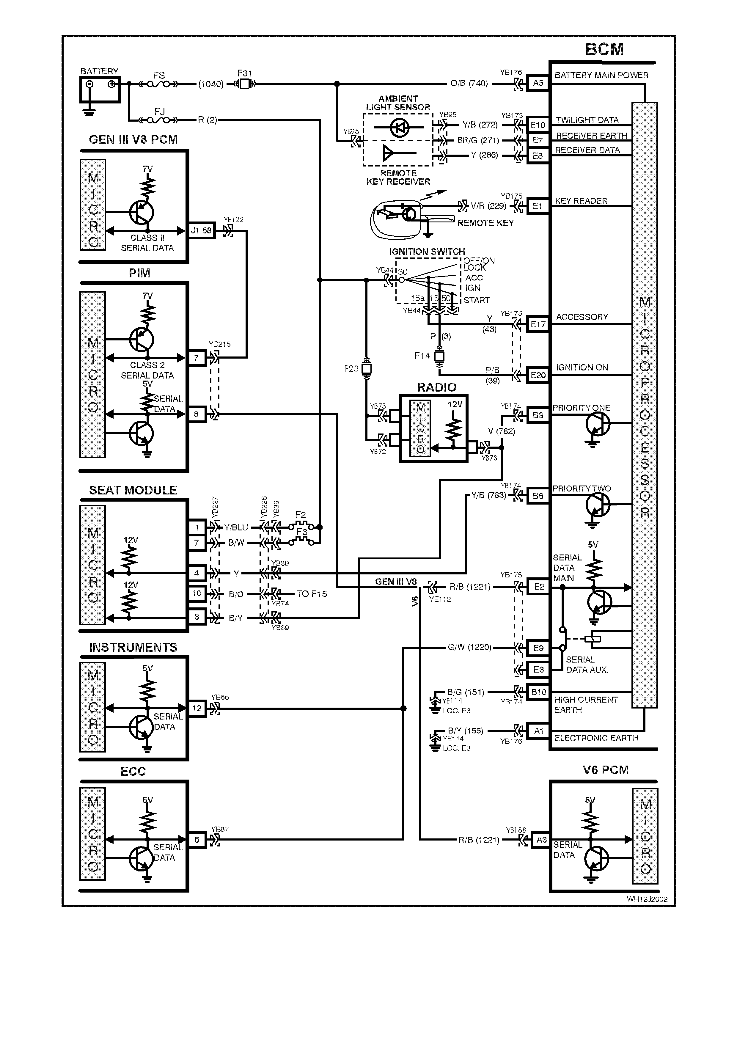
Figure 12J-2-4

PRIORITY KEY SYSTEM
STEP ACTION VALUE YES NO
1. • Operate the UNLOCK button on both of the priority
one and priority two remote coded keys alternatively.
• Check the automatic headlamp off time delay
memories as set in Step 7 of the pre-requisite
diagnostic test in this Section.
• Is the automatic headlamp off delay memory recalled
for both keys?
Go to Step 2. Go to Step 11.
2. • Operate the UNLOCK button on both of the priority
one and priority two remote coded keys alternatively.
• Check the antenna height memory as set in Step 7
of the pre-requisite diagnostic test in this Section.
• Is the antenna height memory recalled for both
keys?
Go to Step 3. Replace BCM,
refer to 12J
HIGH SERIES
BCM of the VT
Series I Service
Information.
Recheck and
verify repair.
3. • Operate the UNLOCK button on both of the priority
one and priority two remote coded keys alternatively.
• Check the instrument dimmer level memory as set in
Step 7 of the pre-requisite diagnostic test in this
Section.
• Is the instrument dimmer level memory recalled for
both keys?
Go to Step 4. Replace BCM,
refer to 12J
HIGH SERIES
BCM of the VT
Series I Service
Information.
Recheck and
verify repair.
4. • Operate the UNLOCK button on both of the priority
one and priority two remote coded keys alternatively.
• Check the trip computer, mode and overspeed
setting memories as set in Step 7 of the pre-requisite
diagnostic test in this Section.
• Are the trip computer, mode and overspeed setting
memories recalled for both keys?
Go to Step 5. Go to Step 8.
5. • Operate the UNLOCK button on both of the priority
one and priority two remote coded keys alternatively.
• Check the climate control setting memory as set in
Step 7 of the pre-requisite diagnostic test in this
Section.
• Is the climate control setting memory recalled for
both keys?
Go to Step 6. Go to ECC
diagnosis, refer
Section 2C AIR
CONDITIONING
of the WH
Service
Information.
6. • Operate the UNLOCK button on both of the priority
one and priority two remote coded keys alternatively.
• Check the radio setting memory as set in Step 7 of
the pre-requisite diagnostic test in this Section.
• Is the radio setting memory recalled for both keys?
Statesman -
System OK.
Caprice -
Go to Step 7.
Go to Step 9.
7. • Operate the UNLOCK button on both of the priority
one and priority two remote coded keys alternatively.
• Check the drivers seat and external rear view mirror
setting memory as set in Step 7 of the pre-requisite
diagnostic test in this Section.
• Are the drivers seat and external rear view memory
settings recalled for both keys?
System OK. Go to Step 13.
8. • Connect TECH 2 to DLC.
• Select BODY / INSTRUMENTS turn ignition ON, as
instructed and press CONFIRM.
• Does TECH 2 communicate with the instruments, by
displaying SYSTEM IDENTIFICATION information?
Go to
Instruments
diagnosis in
Section 12C
INSTRUMENTS,
WIPERS /
WASHERS AND
HORNS of the
VT Series II
Service
Information.
Go to serial data
communication
diagnosis, refer
to 12J HIGH
SERIES BCM of
the VT Series II
Service
Information.
Recheck and
verify repair.
9. • Disconnect BCM connector YB174 and back probe
harness side of terminal B3, circuit 782 (Violet wire)
with a jumper lead to earth.
• Turn ignition and radio ON.
• By connecting and disconnecting jumper lead, do
radio settings change?
Replace BCM,
refer to 12J
HIGH SERIES
BCM of the VT
Series I Service
Information.
Recheck and
verify repair.
Go to Step 10.

PRIORITY KEY SYSTEM, continued
STEP ACTION VALUE YES NO
10. • Check integrity of circuit 782 (Violet wire).
• Is circuit 782 OK? Replace radio,
refer Section 12D
AUDIO SYSTEM
of the VT Series I
Service
Information.
Repair circuit 782
as necessary.
Recheck and
verify repair.
11. • Connect TECH 2 to DLC.
• Select BODY / BODY CONTROL MODULE / DATA
DISPLAY and scroll to KEY PRIORITY SIGNAL.
• Operate the UNLOCK button on both the priority one
and priority two remote keys alternatively.
• Does screen display alternate between 1 and 2?
Replace BCM,
refer to 12J
HIGH SERIES
BCM of the VT
Series I Service
Information.
Recheck and
verify repair.
Go to Step 12.
12. • In Step 11, are both remote keys set to priority one? Program new
remote coded
key.
Using TECH 2,
program one of
the remote keys
to priority one.
13. • Turn ignition off.
• Disconnect BCM connector YB174 and back probe
terminal B3, circuit 782 (Violet wire) with a jumper
lead that can be connected to earth and terminal B6,
circuit 783 (Yellow/Black wire) with a jumper lead
that can be connected to earth.
NOTE: Do not connect jumper leads to earth at this
stage.
• Alternating each earth connection on the jumper
leads, connect one of the jumper leads to earth for
one second and release earth connection. Connect
the earth lead of the other jumper lead to earth for
one second and release earth connection.
• Do the external rear vision mirrors and driver’s seat
change settings from priority one to priority two?
Replace BCM,
refer to 12J
HIGH SERIES
BCM of the VT
Series I Service
Information.
Recheck and
verify repair.
Go to Step 14
14. • Check integrity of circuits 782 (Violet wire) and 783
(Yellow/Black wire).
• Are circuits OK?
Go to memory
adjustable
drivers seat and
external rear
vision mirrors
diagnosis, refer
Section 1A7
SEAT AND
SEAT BELT
ASSEMBLIES of
the WH Service
Supplement.
Repair circuits
782 and/or 783
as necessary.
Recheck and
verify repair.