
SECTION 12N - FUSES, RELAYS AND WIRING
HARNESSES
1. GENERAL INFORM ATION
1.1 FUSES AND CIRCUIT BREAKERS
All fuses and circuit breakers for WH Models carryover from VT Series Models and are as described in
Section 12N, FUSES, REALYS AND WIRING HARNESSES, of the VT Series I Service Information and
Section 12N, FUSES, REALYS AND WIRING HARNESSES, of the VT Series II Service Information, except as
follows:
1. Additional fuses have been added to the passenger compartment fuse and relay assembly, refer Fig 12N-1.
a. Fuse F3 added for memory seat and sunroof functions.
b. Fuse F8 added for the automatic level ride system.
2. Fuse F9 (LPG System) is deleted for WH Series.
For all fuse and circuit breaker circuit protection details, refer to 1 POWER DISTRIBUITON circuit diagram in
Section 12P, WIRING DIAGRAMS, of this Service Information Supplement.
IMPORTANT
Before performing any Service Operation or other procedure described in this Section, refer to
Section 00 CAUTIONS AND NOTES for correct workshop practices with regard to safety and
torquing procedures.
Techline

1.2 RELAYS
All relays for WH Models carryover from VT Series Models and are as described in :
Section 12N, FUSES, REALYS AND WIRING HARNESSES, of the VT Series I Service Information
and
Section 12N, FUSES, REALYS AND WIRING HARNESSES, of the VT Series II Service Information, except as
follows:
1. The LPG system relay is not required and is therefore a spare relay in the passenger compartment fuse and
relay panel assembly, refer Fig 12N-1 following.
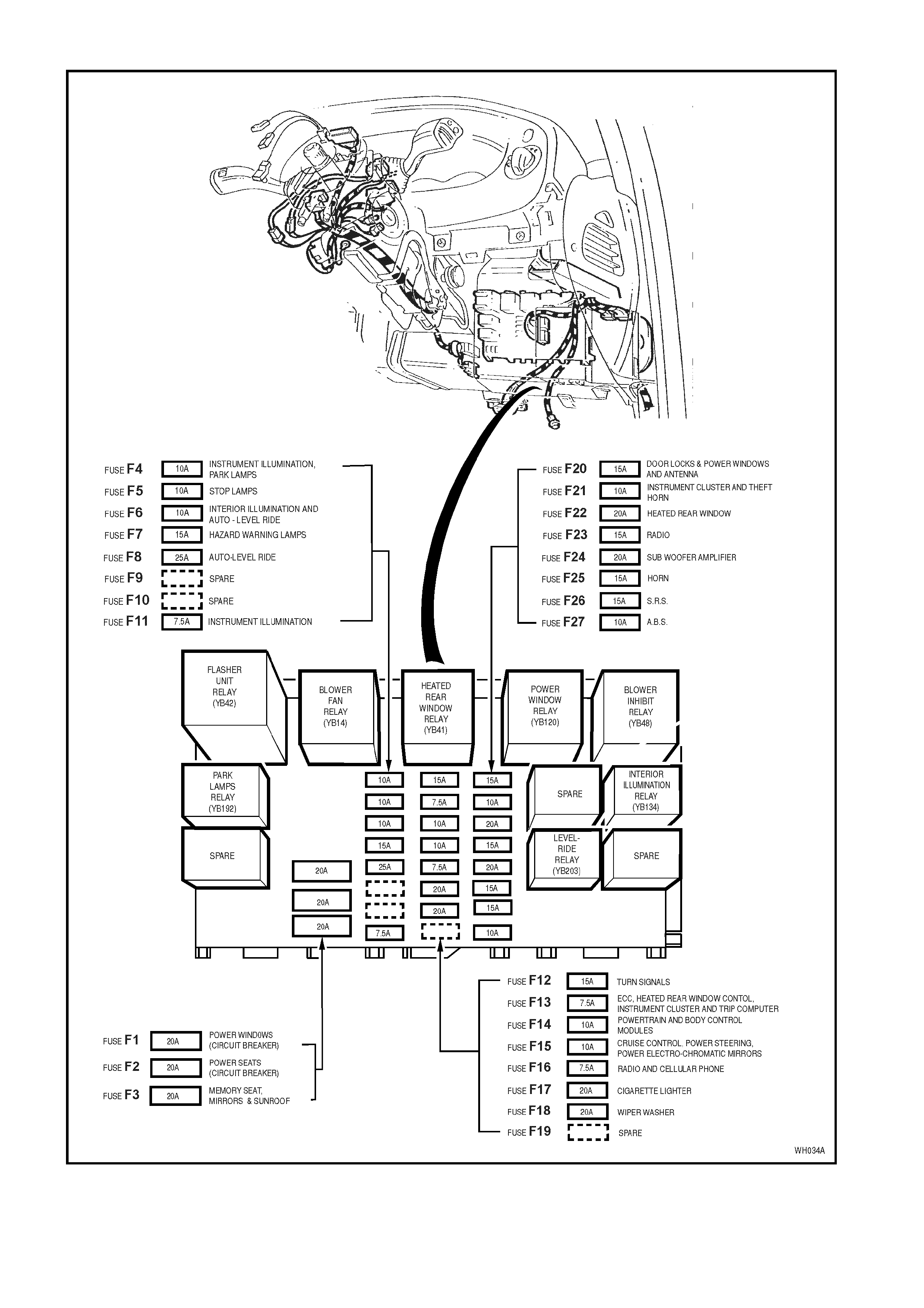
Figure 12N-1


3. WIRING INSTALLATION DIAGRAMS
The following figures in this Section illustrate the new vehicle wiring installation diagrams, specific for WH Series
Models. All remaining wiring installation diagrams are carryover from VT and VT Series II Models and are covered
in Section 12N, FUSES, RELAYS AND WIRING HARNESSES, of the VT Series I Service Information and
Section 12N, FUSES, RELAYS AND WIRING HARNESSES, of the VT Series II Service Information.
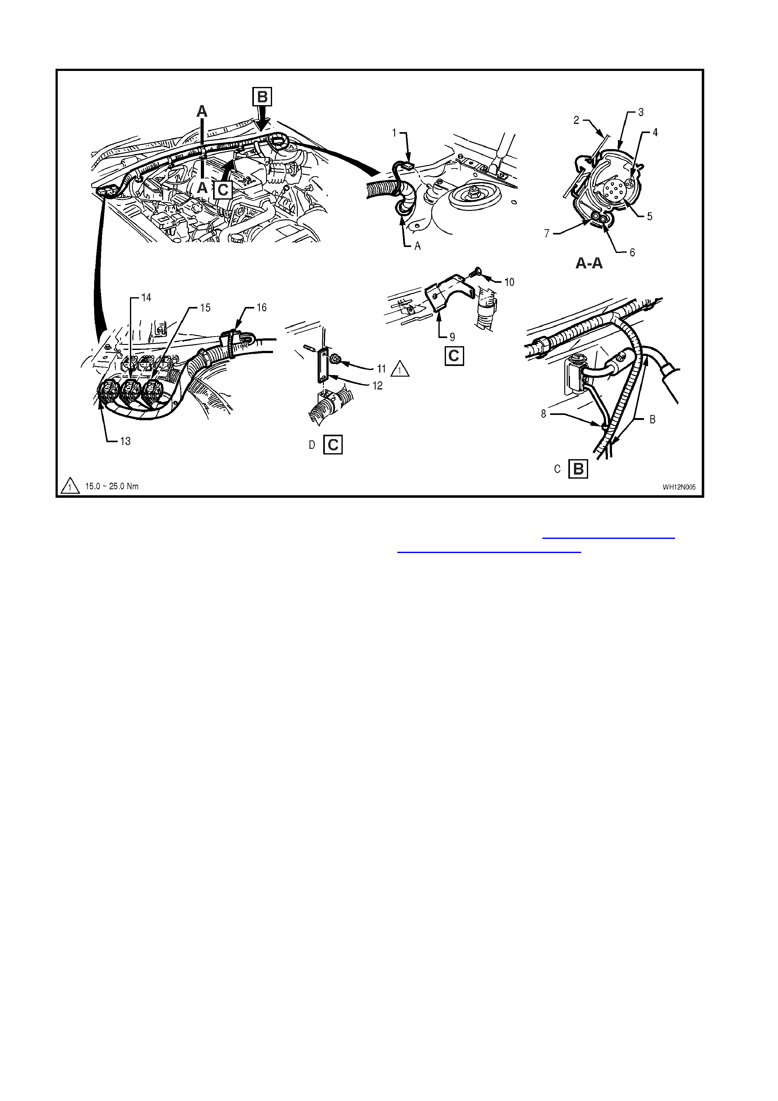
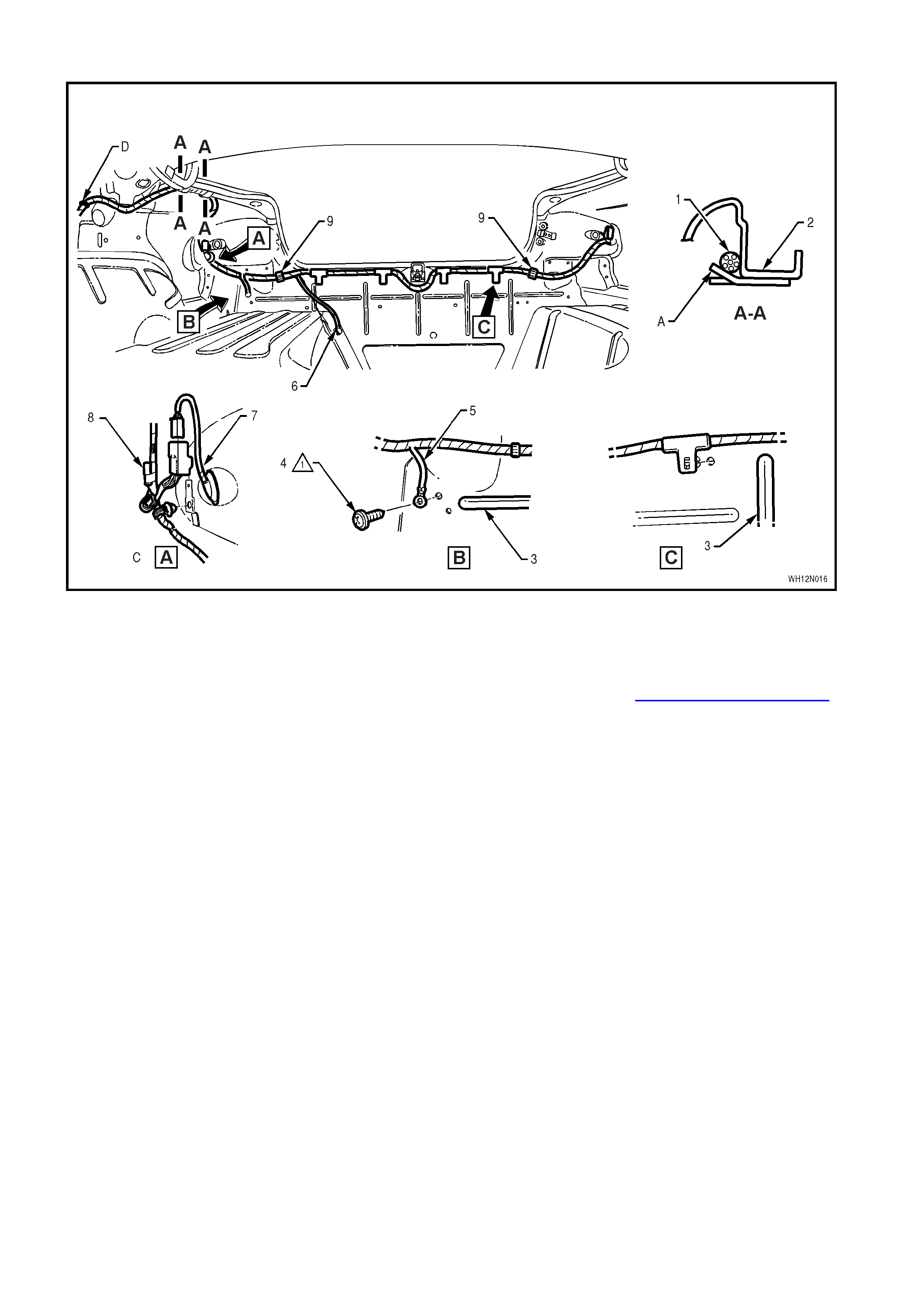
POWERTRAIN HARNESS – 1 ALL MODELS WITH V6 ENGINE
Legend
1. Theft Deterrent Horn Connector
2. Dash Upper Panel Assembly
3. Clamp (5 Places)
4. Main W i ring Harness – To Wiper Motor
5. Powertrain Harness
6. Throttle Cable
7. Cruise Control Cable
8. Clip (Part of wiring harness, attaches to Air
Conditioning liquid line)
9. Harness Support Bracket
10. Screw
11. Nut
12. Harness Support Bracket
13. Powertrain Harness Engine Connector 3
14. Powertrain Harness Engine Connector 2
15. Powertrain Harness Engine Connector 1
16. Powertrain Harness Engine Connector 4
A. For continuation, refer to Section 12N – FUSES,
RELAYS & WIRING HARNESSES, of the VT Series
II Service Information, POWERTRAIN HARNESS –
6 diagram.
B. Powertrain harness must be routed in front of Air
Conditioning suction and liquid lines.
C. View shows vehicle fitted with V6 supercharged
engine.
D. View shows vehicle fitted with nornally aspirated V6
engine.
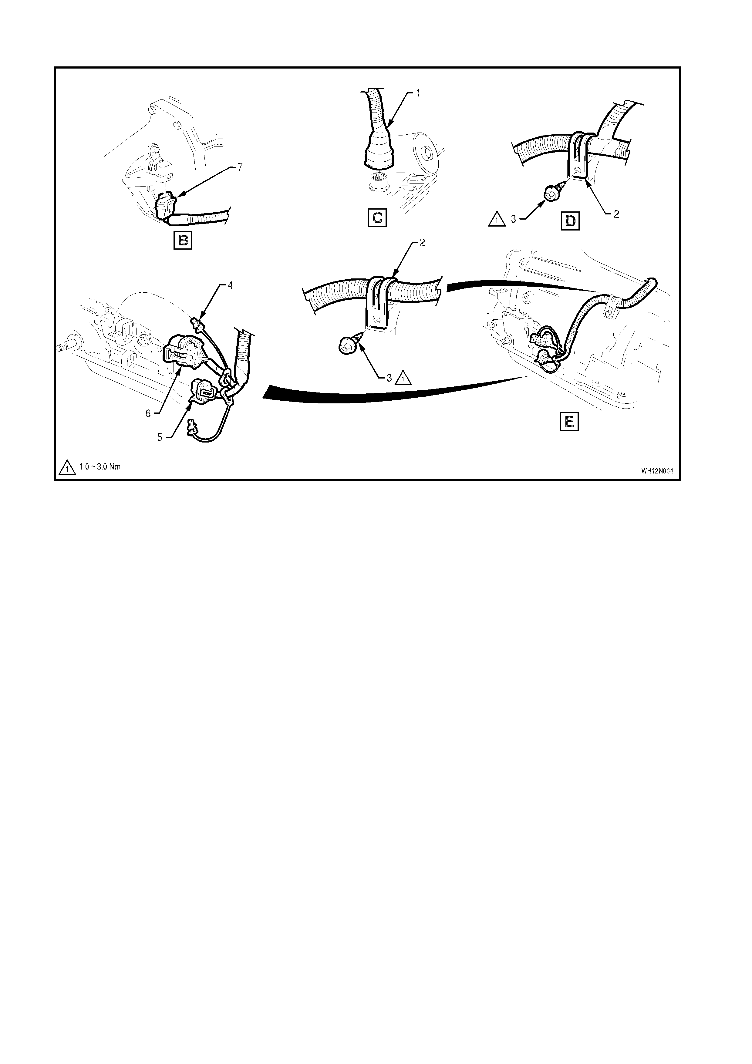
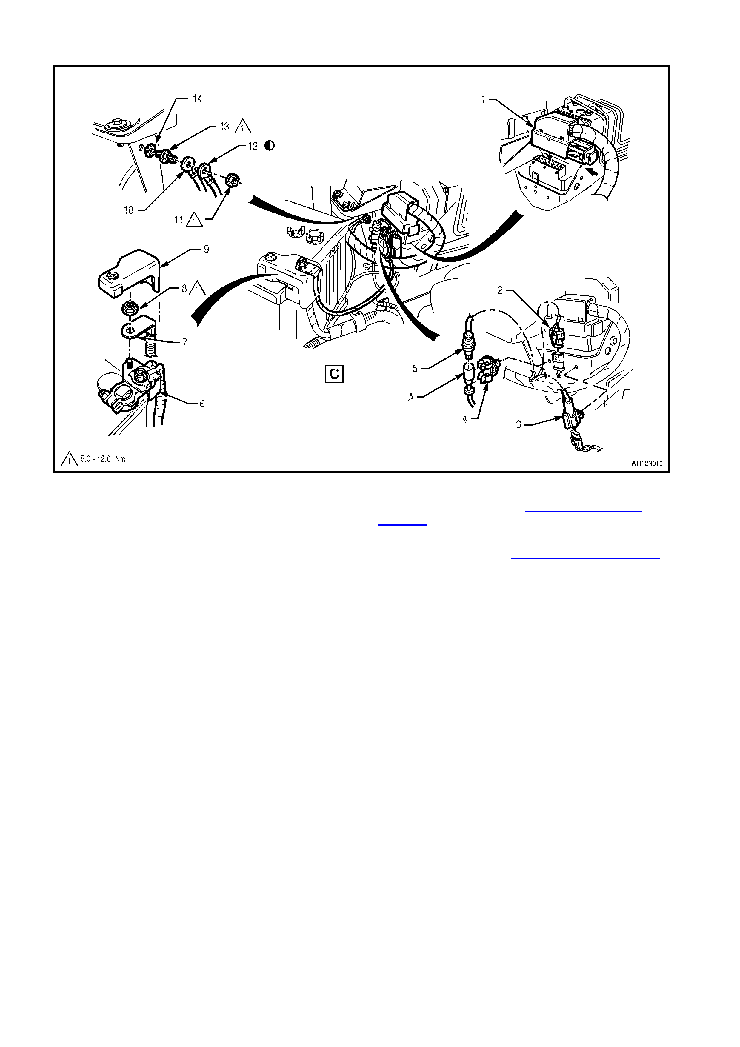
POWERTRAIN HARNESS – 2 ALL MODELS
Legend
1. Powertrain Harness Pass Thru Connector
2. Clip
3. Screw
4. CPA Lock
5. PRNDL Connector
6. Neutral Start/Back-Up Lamp Switch Connector
7. Transmission Speed Sensor Connector
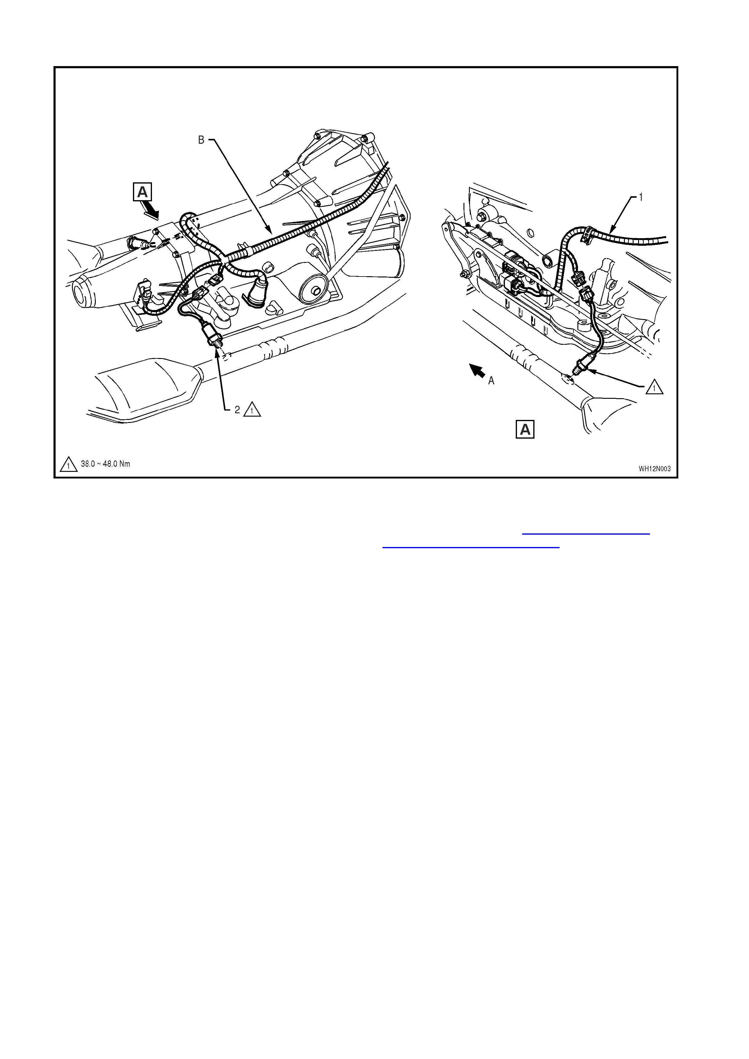
POWERTRAIN HARNESS – 3 ALL MODELS WITH GEN III V8 ENGINE – EXHAUST GAS OXYGEN SENSORS
Legend
1. Powertrain Harness
2. Exhaust Gas Oxygen Sensor (2 Places) A. Front of vehicle
B. For continuation, refer to Section 12N – FUSES,
RELAYS & WIRING HARNESSES, of the VT Series
II Service Information, POWERTRAIN HARNESS –
5 diagram.
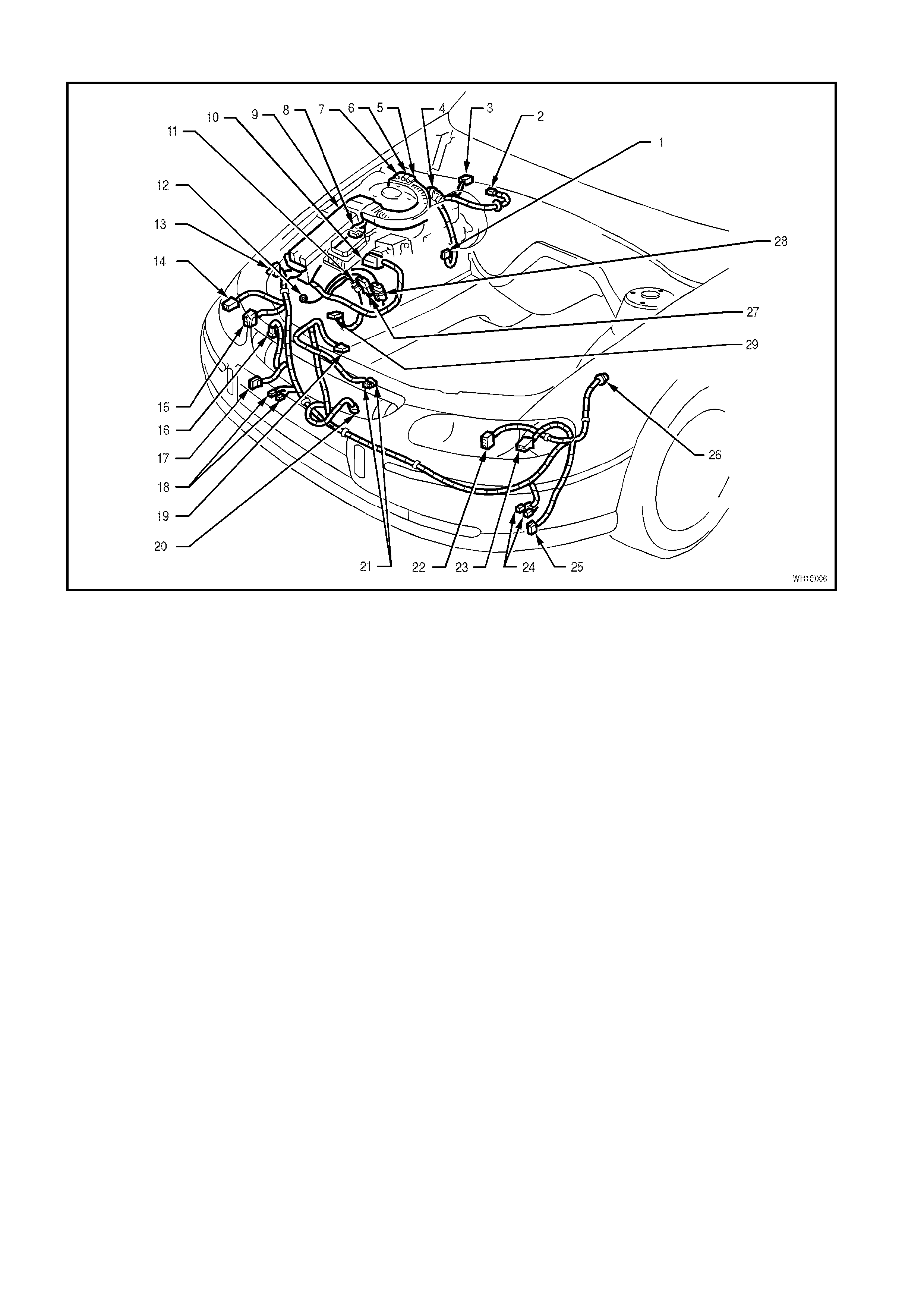
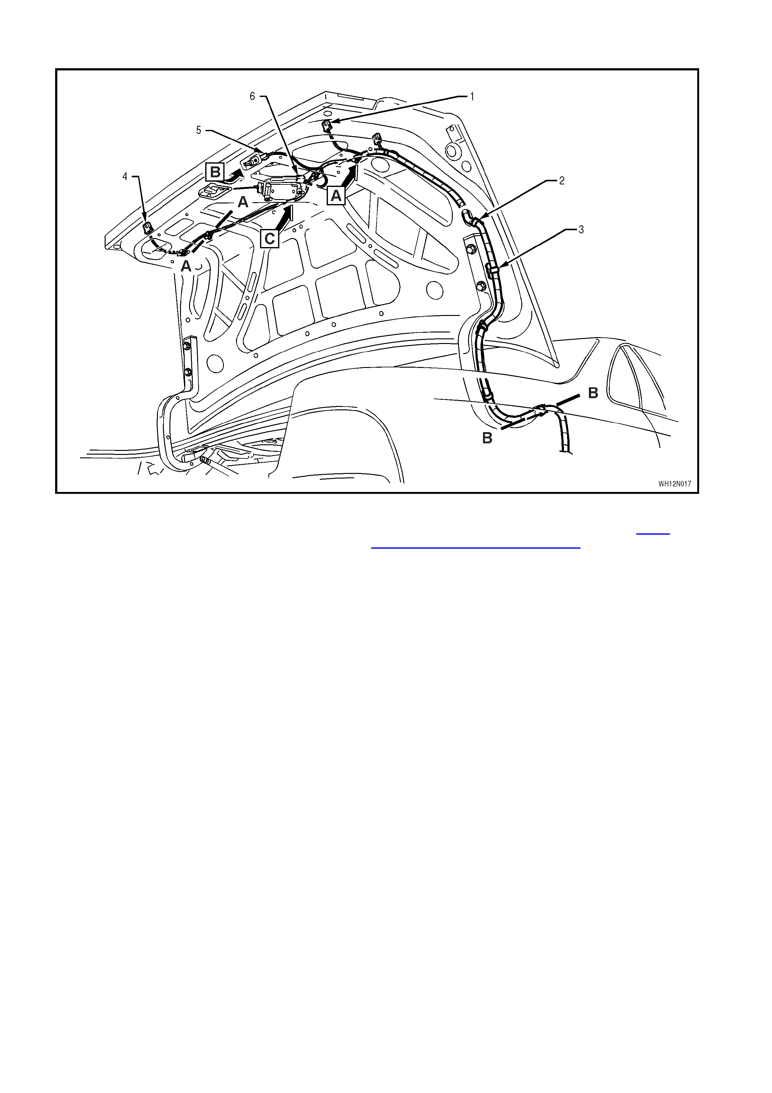
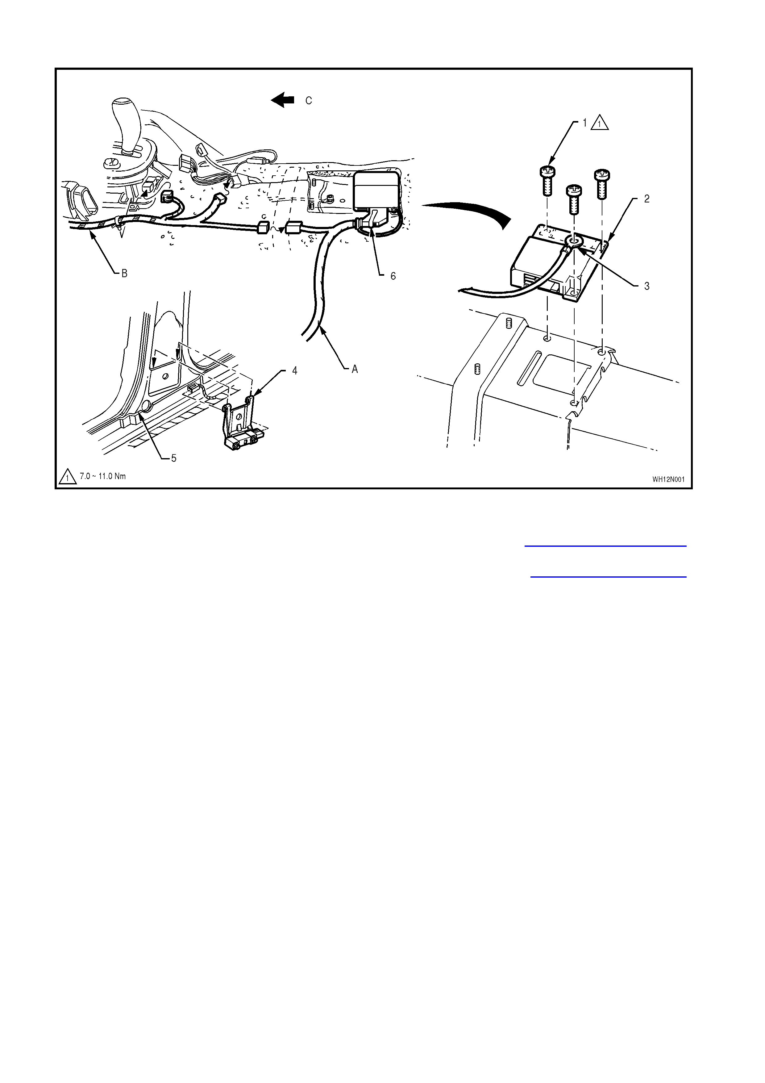
MAIN WIRING HARNESS – 1 ENGINE COMPARTMENT - ALL MODELS
Legend
1. Brake Failure Warning Switch Connector
2. Wiper Motor Connector
3. Powertrain Harness Engine Connector 4
4. Diagnostic Interconnect Connector
5. Powertrain Harness Engine Connector 1
6. Powertrain Harness Engine Connector 2
7. Powertrain Harness Engine Connector 3
8. Cruise Control Module Connector
9. Engine Compartment Fuse And Relay
Assembly
10. ABS/ETC Hydraulic Modulator/Intergrated
Contol Module Connector
11. ABS Wheel Speed Sensor – Right Hand Side
12. Body Earth Terminal
13. Body Earth Connector
14. Front Turn Signal Lamp Connector – Right
Hand
15. Front Headlamp – Right Hand
16. Washer Pump Connector
17. Fog/Cornering Lamp Connector – Right Hand
18. Horn Connectors – Right Hand
19. Engine/Condensor Fan Motor Connectors
20. Ambient Sensor Connector
21. Theft Deterrent Hood Switch Connector
22. Front Headlamp – Left Hand
23. Front Turn Signal Lamp Connector – Left Hand
24. Horn Connectors – Left Hand
25. Fog/Cornering Lamp Connector – Left Hand
26. ABS Wheel Speed Sensor – Left Hand Side
27. Power Steering Solenoid Connector
28. Main W i ring Harness To Battery Harness Connector
29. Main Wiring Harness To Battery Positive Terminal
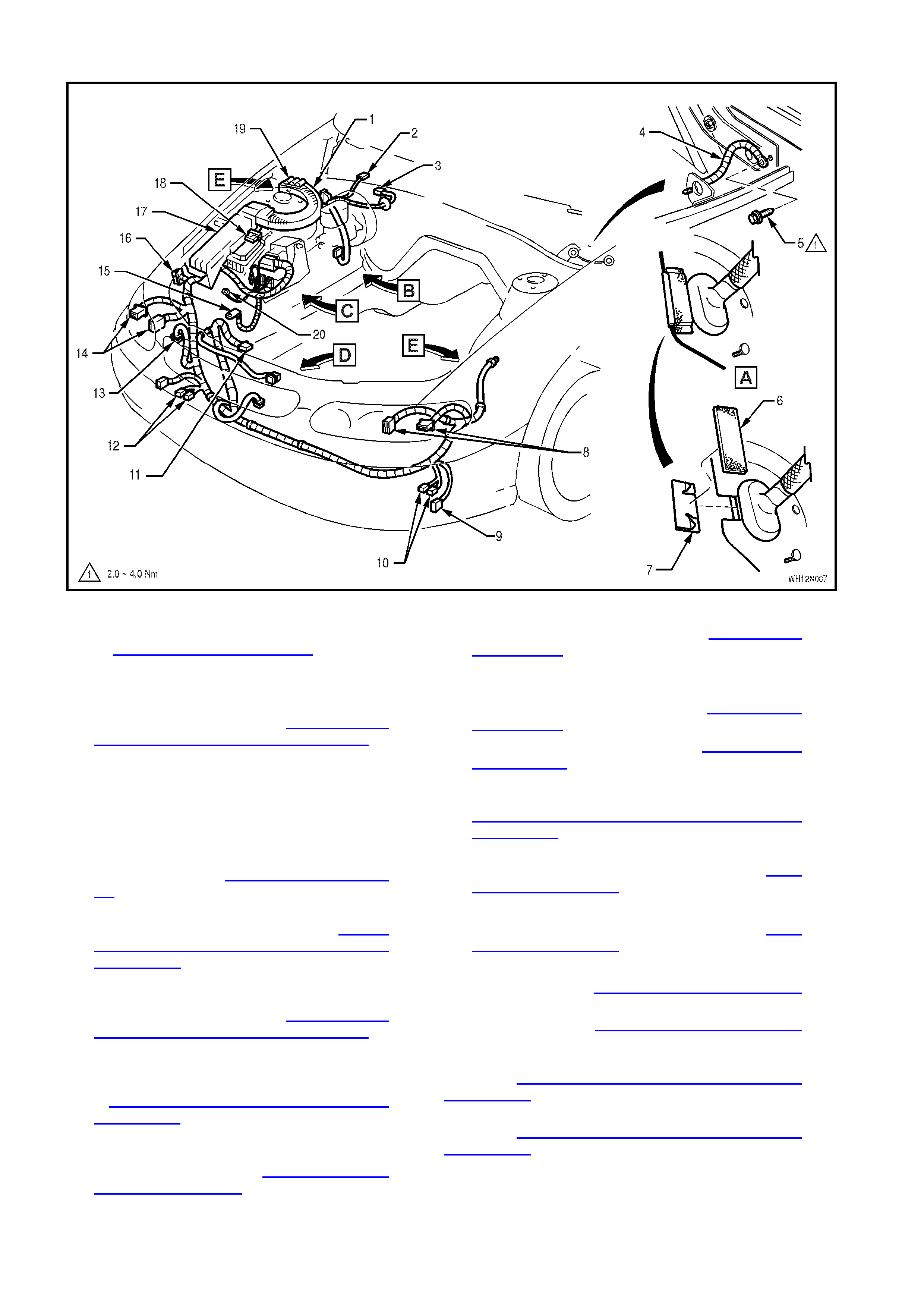
MAIN WIRING HARNESS – 2 ENGINE COMPARTMENT - ALL MODELS
Legend
1. Main W iring Harness Protector Assembly (refer
to MAIN WIRING HARNESS – 3 diagram in
this Section)
2. Powertrain Harness Engine Connector
3. W iper Motor Connector (refer to MAIN WIRING
HARNESS – 3 diagram in Section 12N –
FUSES, RELAYS & WIRING HARNESSES, of
the VT Series I Service Information)
4. Earth Strap
5. Screw
6. Sealing Patch Grommet
7. Grommet Insert
8. Headlamp And Turn Signal Lamp Connectors
– Left Hand (refer to MAIN WIRING HARNESS
- 4 diagram in Section)
9. Fog/Cornering Lamp Connector (refer to MAIN
WIRING HARNESS – 7 diagram in Section
12N – FUSES, RELAYS & WIRING
HARNESSES, of the VT Series I Service
Information)
10. Horn Connectors (refer to MAIN WIRING
HARNESS – 7 diagram in Section 12N –
FUSES, RELAYS & WIRING HARNESSES, of
the VT Series II Service Information)
11. Engine/Condensor Fan Motor Connectors
(refer to MAIN WIRING HARNESS – 6 diagram
in Section 12N – FUSES, RELAYS & WIRING
HARNESSES, of the VT Series I Service
Information)
12. Horn Connectors refer to MAIN WIRING
HARNESS – 7 diagram in FUSES, RELAYS &
WIRING HARNESSES, of the VT Series II
Service Information))
13. Washer Pump Connectors (refer to MAIN WIRING
HARNESS – 4 diagram in this Section)
14. Headlamp And Turn Signal Lamp Connectors –
Right Hand
15. Battery Harness Terminal (refer to MAIN WIRING
HARNESS – 5 diagram in this Section)
16. Body Earth Connector refer to MAIN WIRING
HARNESS – 4 diagram in this Section)
17. Engine Compartment Fuse And Relay Assembly
(refer to MAIN WIRING HARNESS – 3 diagram in
Section 12N – FUSES, RELAYS & WIRING
HARNESSES, of the VT Series I Service
Information)
18. Cruise Control Module Connector (refer to MAIN
WIRING HARNESS – 3 diagram in this Section)
19. Powertrain Harness Engine Connectors 1, 2 & 3
20. Main Wiring Harness Earth Terminal refer to MAIN
WIRING HARNESS – 5 diagram in this Section)
For View B, refer to MAIN WIRING HARNESS – 3
diagram in this Section.
For View C, refer to MAIN WIRING HARNESS – 5
diagram in this Section.
For View D, refer to MAIN WIRING HARNESS – 5
diagram in Section 12N – FUSES, RELAYS & WIRING
HARNESSES, of the VT Series I Service Information.
For View E, refer to MAIN WIRING HARNESS – 7
diagram in Section 12N – FUSES, RELAYS & WIRING
HARNESSES, of the VT Series I Service Information.
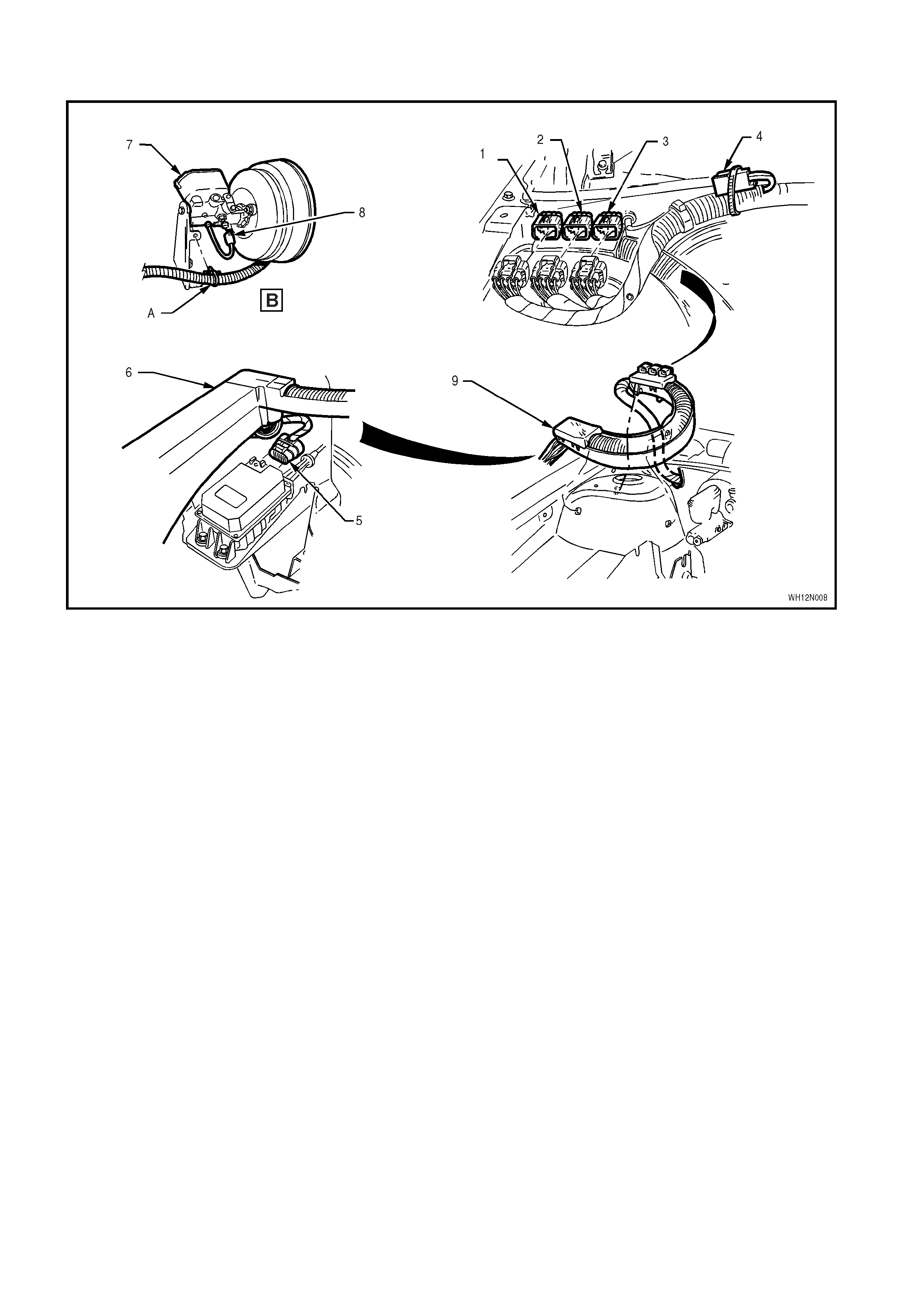
MAIN WIRING HARNESS – 3 - PROTECTOR ASSEMBLY, CRUISE CONTROL AND POWERTRAIN
HARNESS CONNECTORS - ALL MODELS
Legend
1. Powertrain Harness Engine Connector 3
2. Powertrain Harness Engine Connector 2
3. Powertrain Harness Engine Connector 1
4. Powertrain Harness Engine Connector 4
5. Cruise Control Module Connector
6. Engine Compartment Fuse And Relay
Assembly
7. Brake Master Cylinder And Booster Assembly
8. Brake Failure Warning Switch Connector
9. Protector Assembly
A. Main W iring Harness attached to bracket as shown.
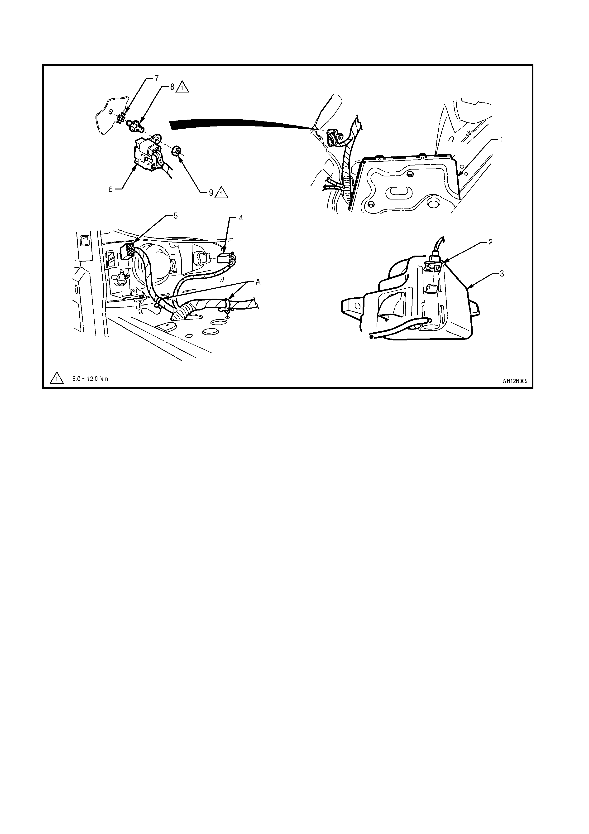
MAIN WIRING HARNESS – 4 - FRONT LAMPS, BODY EARTH AND WASHER PUMP CONNECTORS -
ALL MODELS
Legend
1. Battery Tray
2. Washer Pump Connector
3. Washer Reservoir
4. Front Turn Signal Lamp Connector – Right
Hand
5. Front Headlamp – Right Hand
6. Body Earth Connector
7. Washer
8. Stud
9. Nut
A. Main Wiring Harness attached to inner wheelhouse
on the right hand panel as shown.
MAIN WIRING HARNESS – 5 - ABS, POWER STEERING AND BATTERY CONNECTORS - A LL MODELS
Legend
1. ABS/ETC Hydraulic Modulator/Intergrated
Contol Module Connector
2. Main W iring Harness To Battery Harness
Connector
3. Main Wiring Harness Power Steering
Connector
4. Connector Retaining Clip
5. ABS Wheel Speed Sensor – Right Hand Side
6. Battery Harness Positive Terminal
7. Main Wiring Harness To Battery Positive
Terminal
8. Terminal Nut
9. Battery Positive Terminal Cover
10. Main W iring Harness Body Earth Terminal
11. Nut
12. Battery Harness Body Earth Terminal
13. Stud
14. Washer
A. For continuation, refer to Section 12L ABS &
ABS/ETC of the VT Series II Service Information.
For location of View C, refer to MAIN WIRING HARNESS – 2
diagram in this Section.
MAIN WIRING HARNESS – 6 - POWER STEERING WIRING - ALL MODELS
Legend
1. Main Wiring Harness Power Steering
Connector A. Convoluted conduit clip to be inserted into bracket
on side rail.
B. Conduit is clipped to return pipe.
C. Front of vehicle.
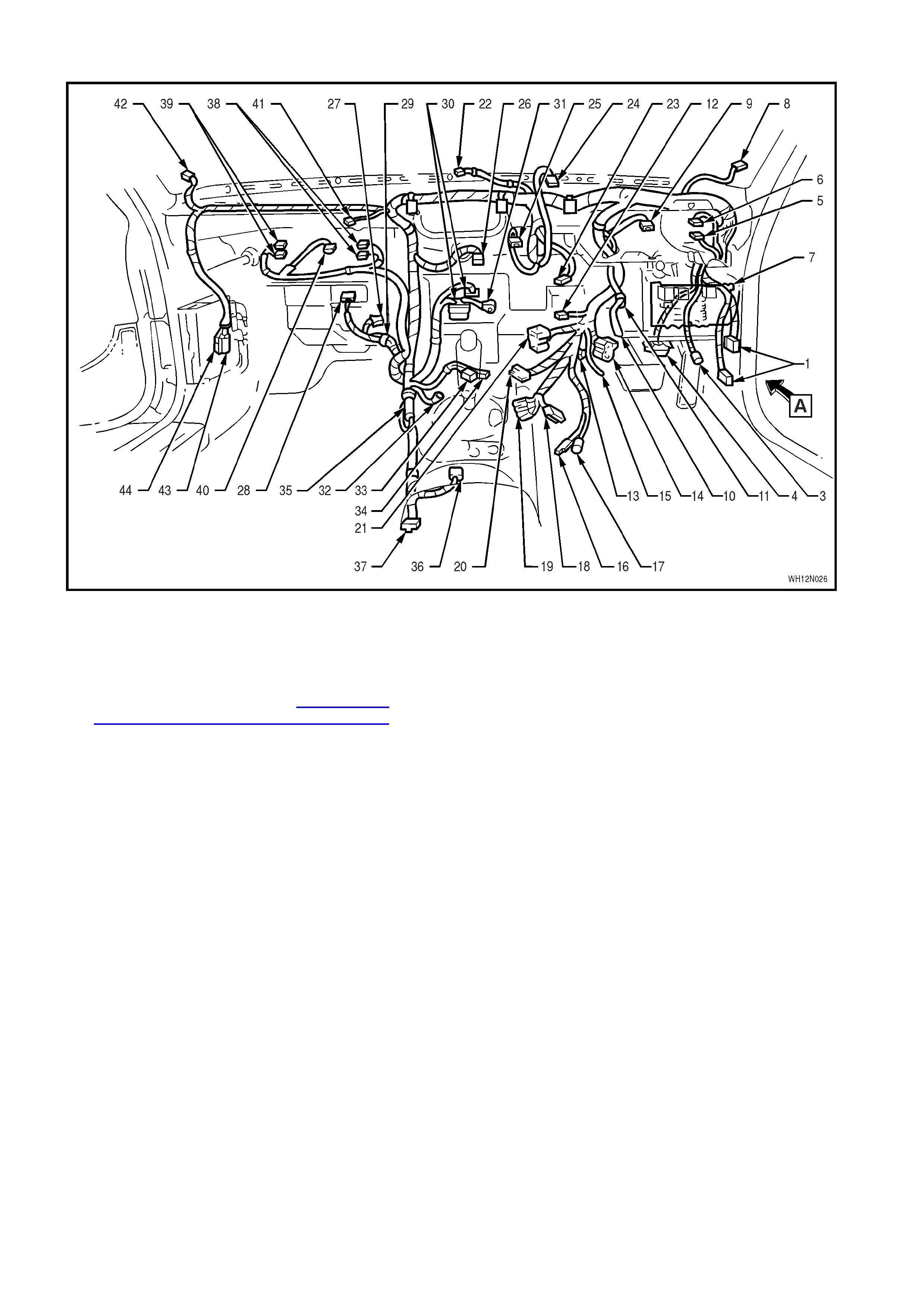
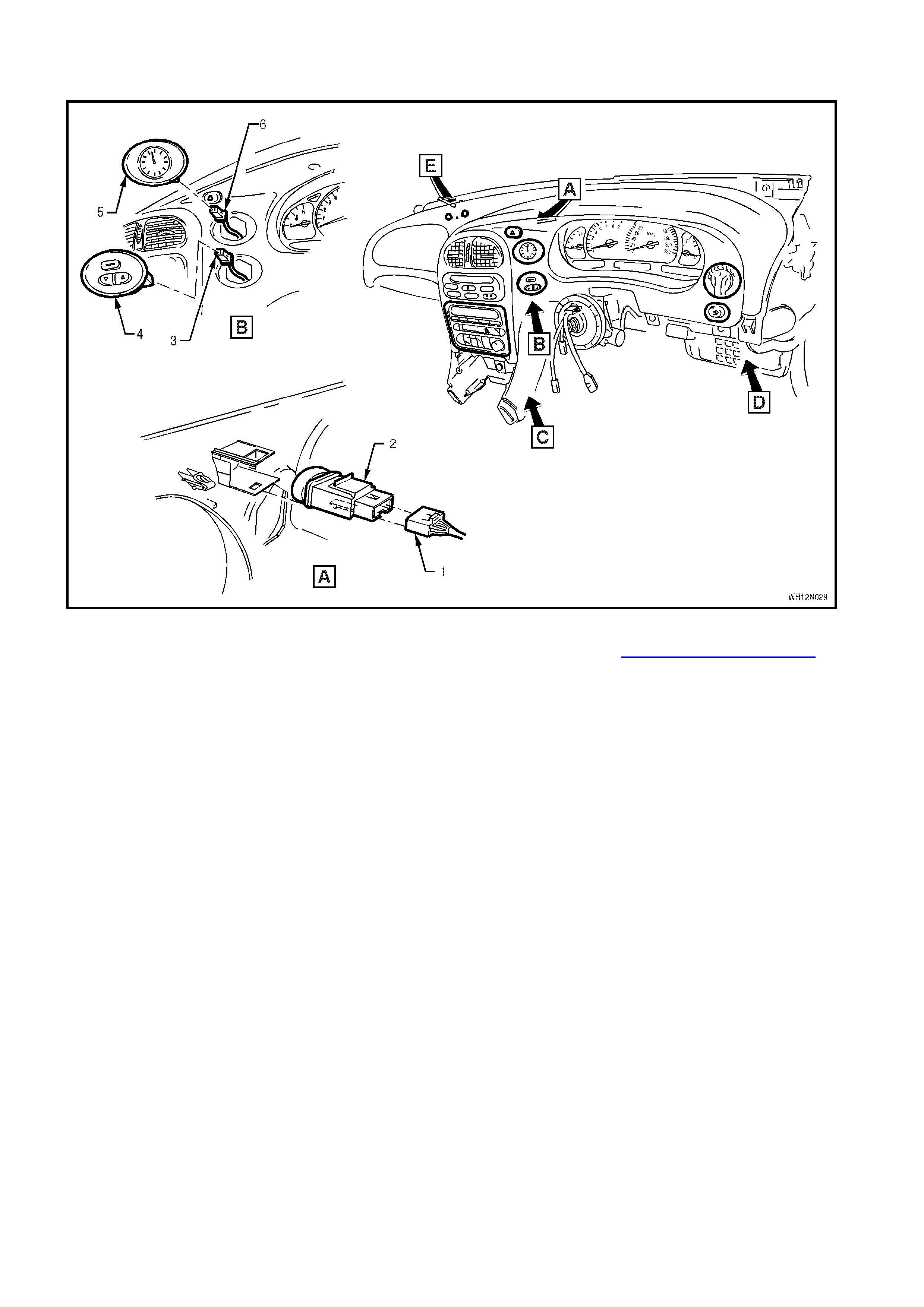
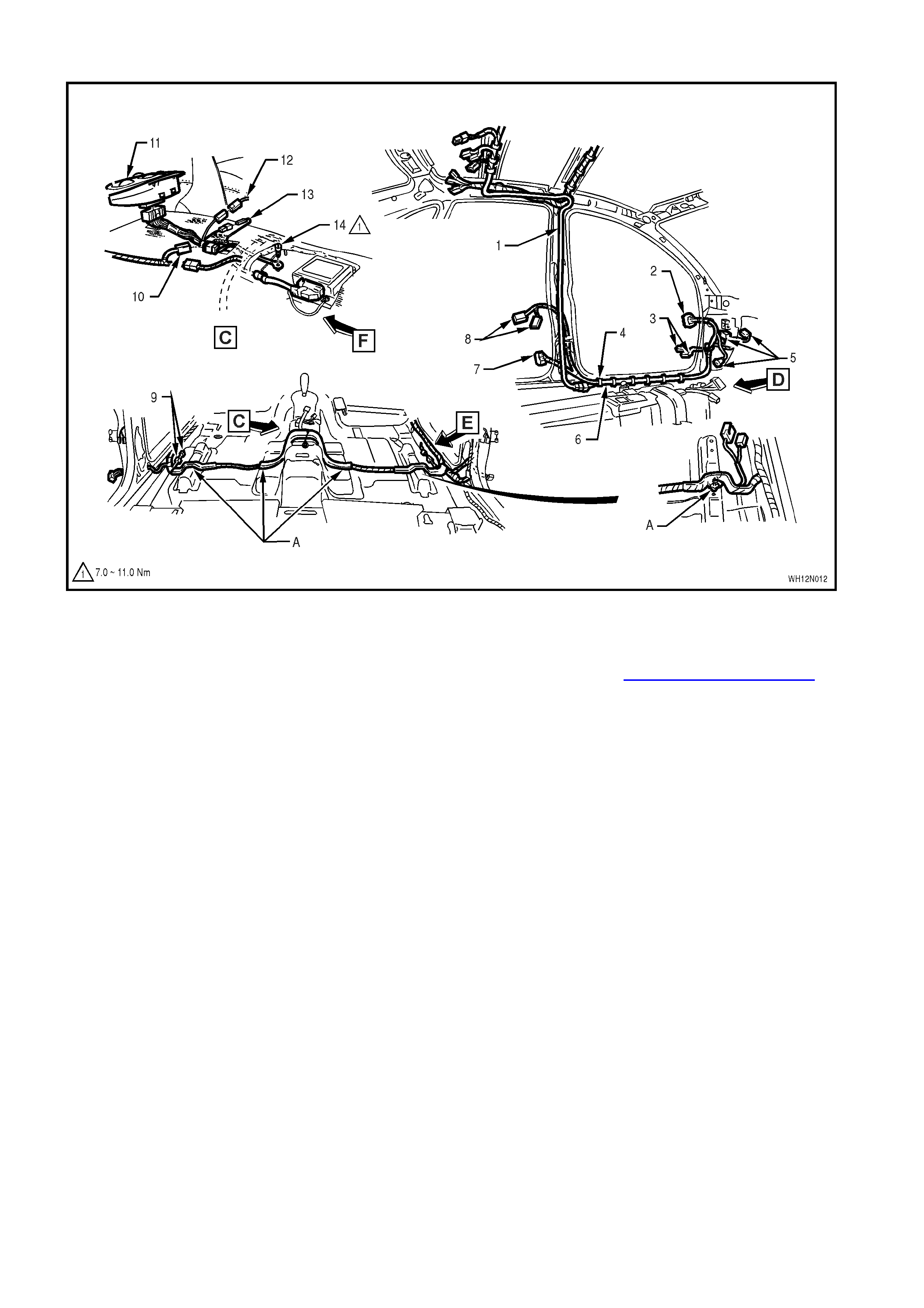
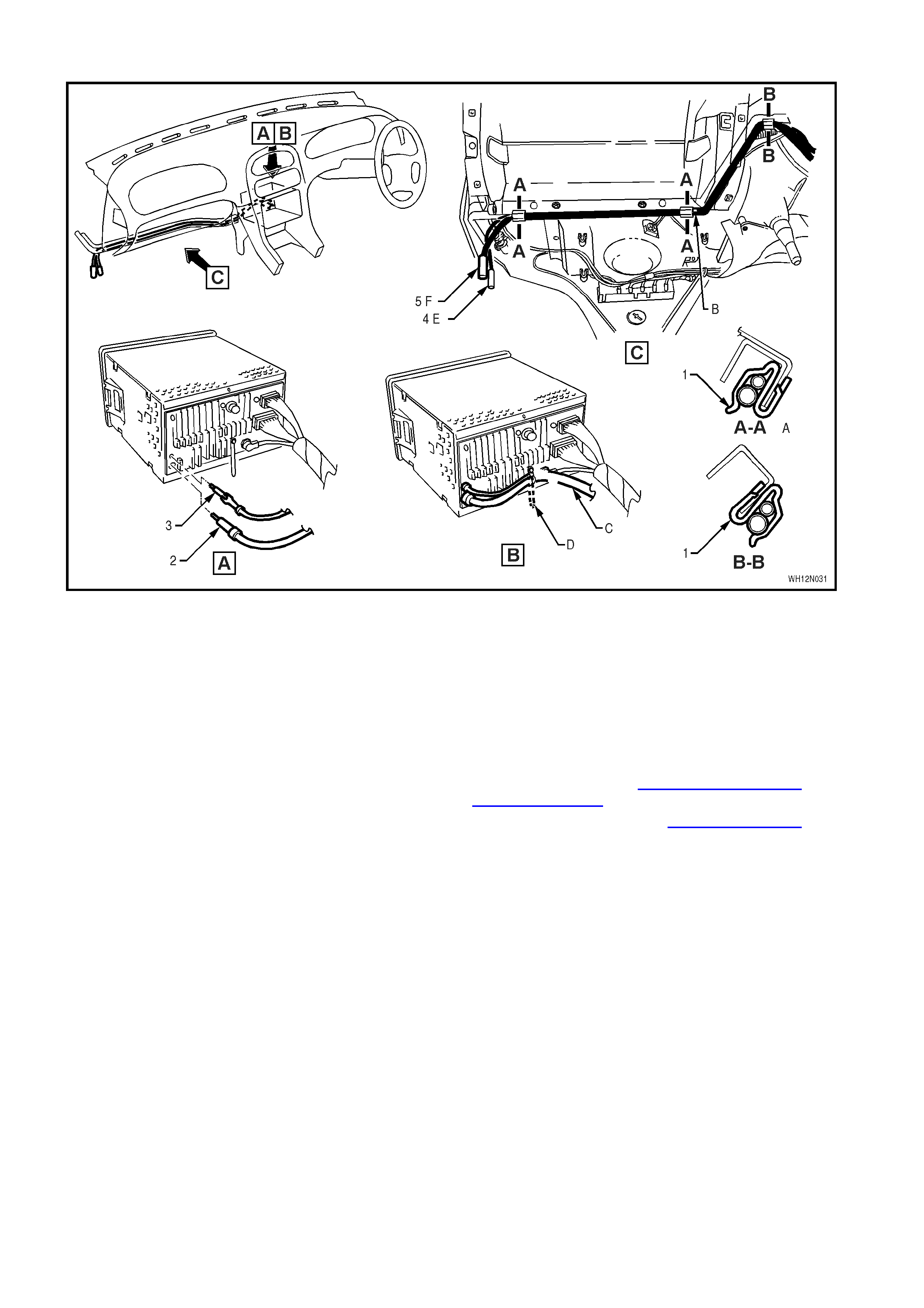
MAIN WIRING HARNESS – 7 - COCKPIT MODULE - ALL MODELS
Legend
1. Main Wiring Harness To Body Harness
Connectors (2 Places)
2. Body Control Module Connectors (4 Places)
(NOT SHOWN – REFER TO MAIN WIRING
HARNESS –14 diagram in Section 12N,
FUSES, RELAYS AND WIRING HARNESSES
of the VT Series I Series Service Information)
3. Footwell Lamp – Right Hand Side
4. Diagnostic Link Connector
5. Fog Lamp Switch Connector
6. Headlamp Switch Connector
7. Passenger Compartment Fuse And Relay
Assembly
8. Instrument Panel Speaker – Right Hand
9. Instrument Cluster Connector
10. Stop Lamp Switch Connector
11. Cruise Control Electrical Release Switch
Connector
12. Cruise Control Switch Connector
13. Wiper Dwell Control Switch
14. Ignition Switch Connector
15. Ignition Key Earth Terminal
16. Ignition Key Reader
17. Ignition Lock Illumination Bulb Socket
18. Turn Signal Switch I Connector
19. Turn Signal Switch II Connector
20. Main Wiring Harness To Clock Spring Coil
Connector
21. Wiper/Washer Switch Connector
22. Solar Sensor Connector
23. In-Car Sensor Connector
24. Hazard Switch Connector
25. Trip Computer Switch Connector
26. Electronic Climate Control Module Connector
27. Fan Speed Control Switch Connector
28. Blower Motor Connector
29. Thermostat Amplifier Connector
30. Radio Connectors (2 Places)
31. Radio-CD Player Connector
32. Radio Body Earth Terminal
33. Accessory Jack Connector
34. Accessory Jack Illumination Socket Connector
35. Cellular Phone/Auxiliary Connector
36. Automatic Transmission Selector Connector
37. Main Wiring Harness To Body Harness (SRS
Interface) Connector
38. Glove Box Switch Connectors (2 Places)
39. Glove Box Lamp Switch Connectors (2 Places)
40. Decklid Lock Switch Connector
41. Main Wiring Harness to Passenger Side Airbag
Inflator Connector
42. Instrument Panel Speaker – Left Hand
43. Main Wiring Harness To CD Changer Wiring
Connector
44. Main Wiring Harness To Diversity Antenna Wiring
Connector
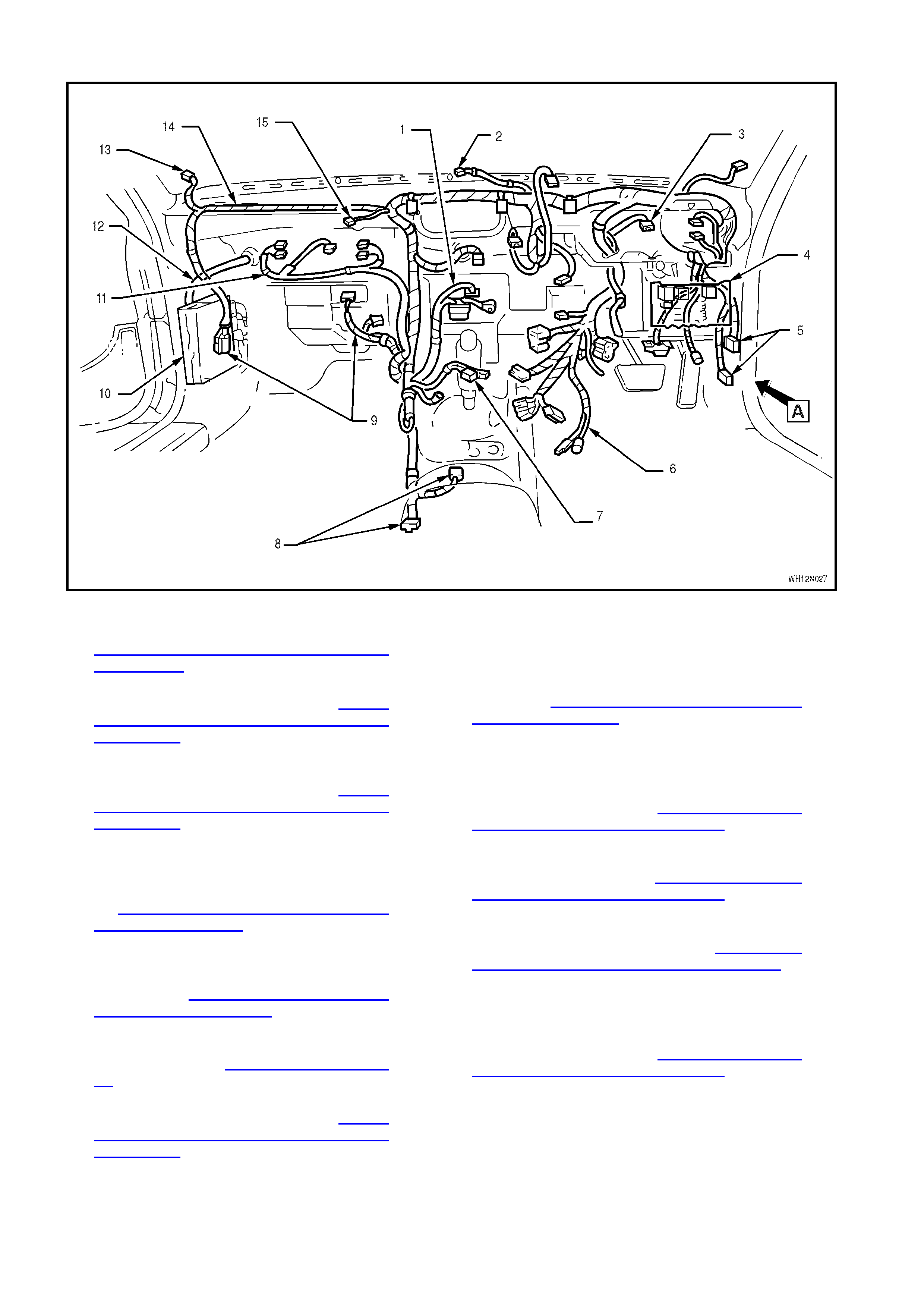
MAIN WIRING HARNESS – 8 - COCKPIT MODULE - ALL MODELS
Legend
1. Radio/Cassette/CD Player Connectors (refer to
ANTENNA & DIVERSITY ANTENNA LEAD
EXTENSIONS diagram in this Section)
2. Solar Sensor Connector (refer to MAIN
WIRING HARNESS – 24 diagram in Section
12N, FUSES, RELAYS AND WIRING
HARNESSES of the VT Series I Series Service
Information)
3. Instrument Cluster Connector (refer to MAIN
WIRING HARNESS – 20 diagram in Section
12N, FUSES, RELAYS AND WIRING
HARNESSES of the VT Series I Series Service
Information)
4. Passenger Compartment Fuse and Relay
Assembly, And Body Control Module (refer to
MAIN WIRING HARNESS – 13 & 14 diagrams
in Section 12N, FUSES, RELAYS AND
WIRING HARNESSES of the VT Series I
Series Service Information)
5. Main Wiring Harness To Body Harness
Connectors (refer to MAIN W IRING HARNESS
– 4 diagram in Section 12N, FUSES, RELAYS
AND WIRING HARNESSES of the VT Series I
Series Service Information
6. Main Wiring Harness To Steering Column
Connectors (refer to MAIN WIRING HARNESS
– 9 diagram in this Section)
7. Accessory Jack Connectors (refer to MAIN
WIRING HARNESS – 18 diagram in Section
12N, FUSES, RELAYS AND WIRING
HARNESSES of the VT Series I Series Service
Information)
8. Transmission and Body Harness Connectors (refer
to SRS WIRING diagram in this Section)
9. Diversity Antenna and Heating, Ventilation and A/C
Connectors (refer to MAIN WIRING HARNESS – 25
diagram in Section 12N, FUSES, RELAYS AND
WIRING HARNESSES of the VT Series I Series
Service Information)
10. Powertrain Control Module – Vehicles With V6
Engine
11. Glove Box Connectors (refer to MAIN WIRING
HARNESS – 26 diagram in Section 12N, FUSES,
RELAYS AND WIRING HARNESSES of the VT
Series I Series Service Information)
12. Powertrain Harness (refer to POWERTRAIN
HARNESS – 1 diagram in Section 12N, FUSES,
RELAYS AND WIRING HARNESSES of the VT
Series I Series Service Information)
13. Instrument Panel Speaker Connector (refer to MAIN
WIRING HARNESS – 24 diagram in Section 12N,
FUSES, RELAYS AND WIRING HARNESSES of
the VT Series I Series Service Information)
14. Main W iring Harness
15. Main Wiring Harness to Passenger Side Airbag
Inflator Connector (refer to MAIN WIRING
HARNESS – 23 diagram in Section 12N, FUSES,
RELAYS AND WIRING HARNESSES of the VT
Series I Series Service Information)
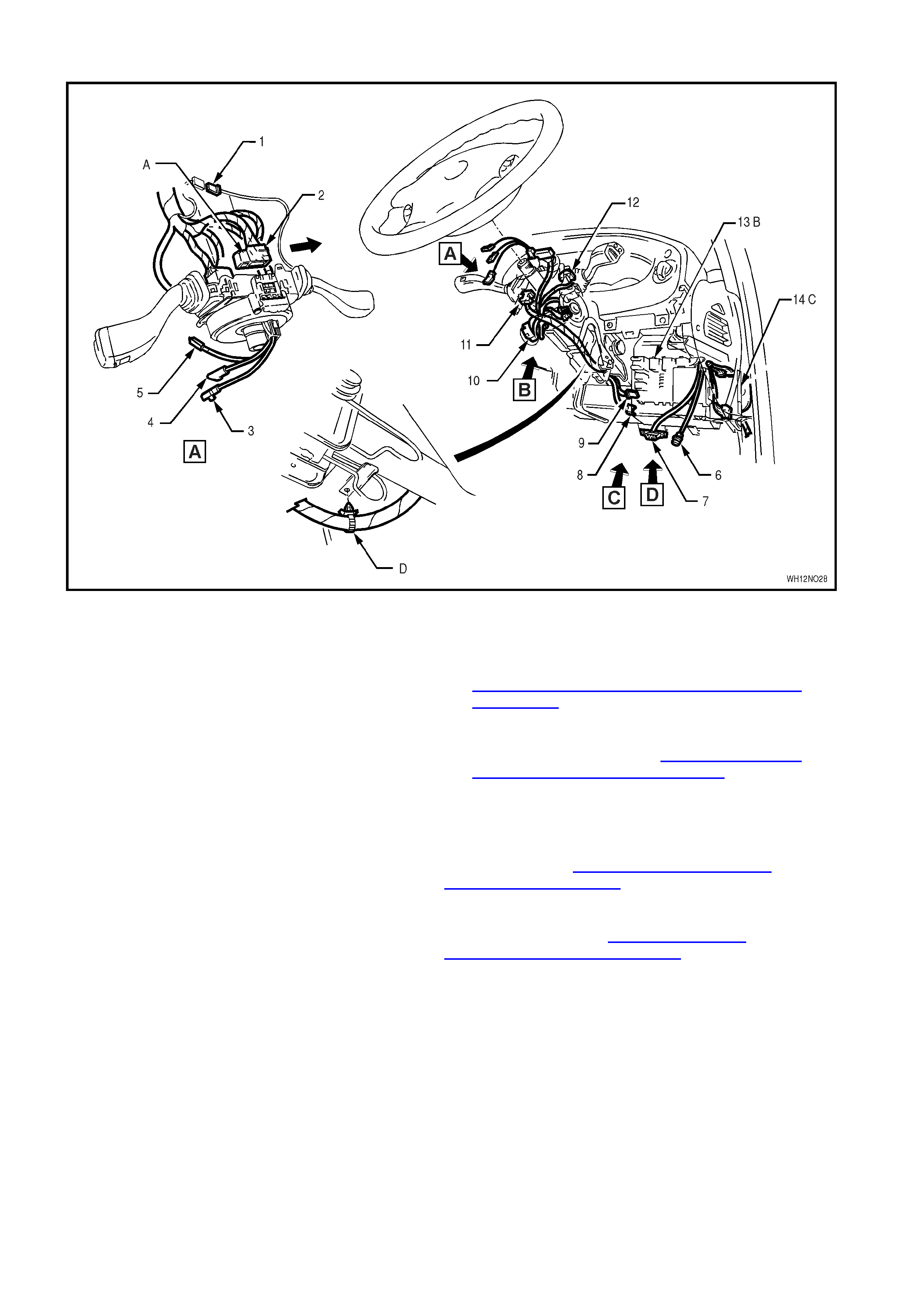
MAIN WIRING HARNESS – 9 - STEERING COLUMN – ALL MODELS
Legend
1. Cruise Control Switch Connector
2. Main Wiring Harness To Clock Spring Coil
Connector
3. Air Bag Inflator Connector
4. Radio Remote Connector
5. Horn Connector
6. Footwell Lamp Connector – Right Hand
7. Diagnostic Link Connector (DLC)
8. Stop Lamp Switch Connector
9. Cruise Control Electrical Release Switch
Connector
10. Ignition Switch
11. Windshield Wiper/Washer Switch Connector
12. Turn Signal I and II Connectors
13. Passenger Compartment Fuse and Relay
Assembly
14. Body Control Module (BCM)
A. Clock spring coil connector installed and secured by
locking retainer in direction of arrow shown.
B. For fuse and relay assembly installaton, refer to
Section 12N, FUSES, RELAYS AND WIRING
HARNESSES of the VT Series I Series Service
Information, MAIN WIRING HARNESS – 13
diagram.
C. For BCM installation, refer to Section 12N, FUSES,
RELAYS AND WIRING HARNESSES of the VT
Series I Series Service Information, MAIN WIRING
HARNESS - 13 & 14 diagrams.
D. Harness atttached to steering column as shown.
For View B, refer to Section 12N, FUSES, RELAYS
AND WIRING HARNESSES of the VT Series I Series
Service Information, MAIN WIRING HARNESS – 17
diagram.
For Views C & D, refer to Section 12N, FUSES,
RELAYS AND WIRING HARNESSES of the VT Series I
Series Service Information, MAIN WIRING HARNESS –
17 diagram.
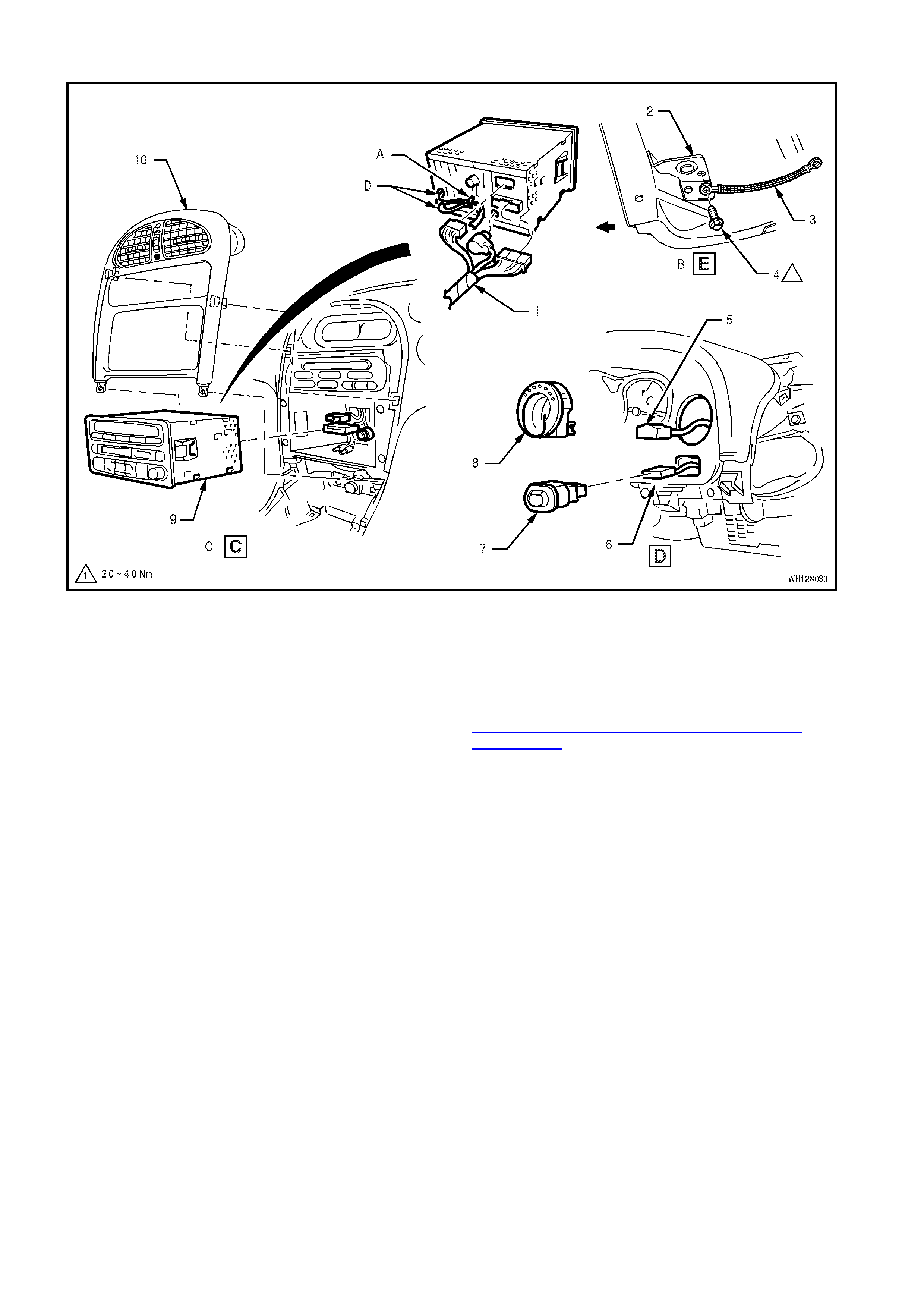
MAIN WIRING HARNESS – 11 - RADIO/CASSETTE/CD & INSTRUMENTS FACIA SWITCHES - ALL MODELS
Legend
1. Radio/Cassette/CD Connectors
2. Cockpit Module Lifting Eye Assembly Bracket
3. Earth Strap
4. Screw
5. Headlamp Switch Connector
6. Fog Lamp Switch Connector
7. Fog Lamp Switch
8. Headlamp Switch
9. Radio/Cassette/CD Player
10. Instrument Facia Escutcheon Assembly
A. Tab bent to hold antenna lead to radio/cassette/CD
player.
B. Left hand side.
C. Vehicles excluding delete radio option.
D. For diversity and power antenna installatoin, refer to
ANTENNA & DIVERSITY ANTENNA LEAD
EXTENSIONS diagram in this Section.
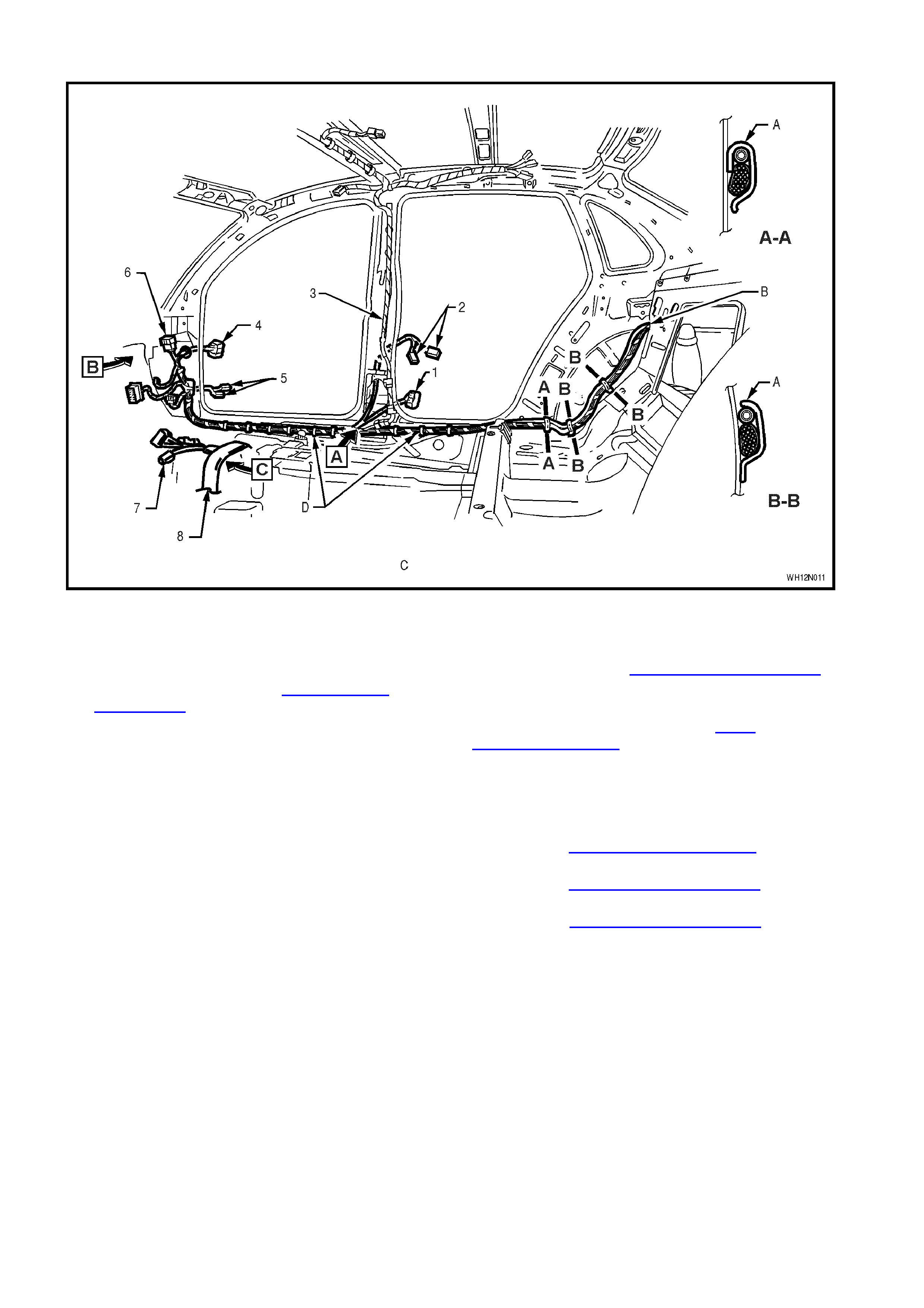
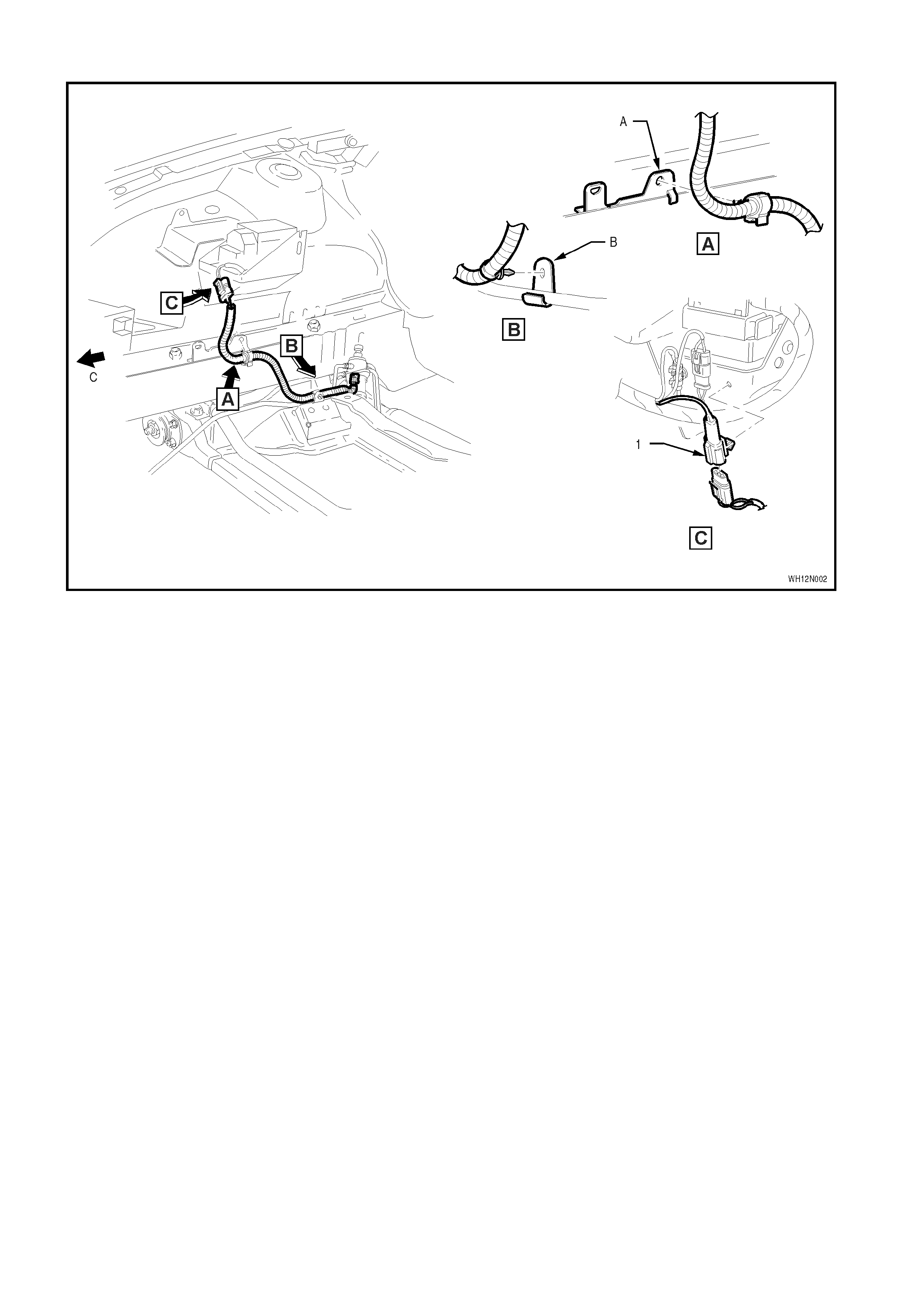
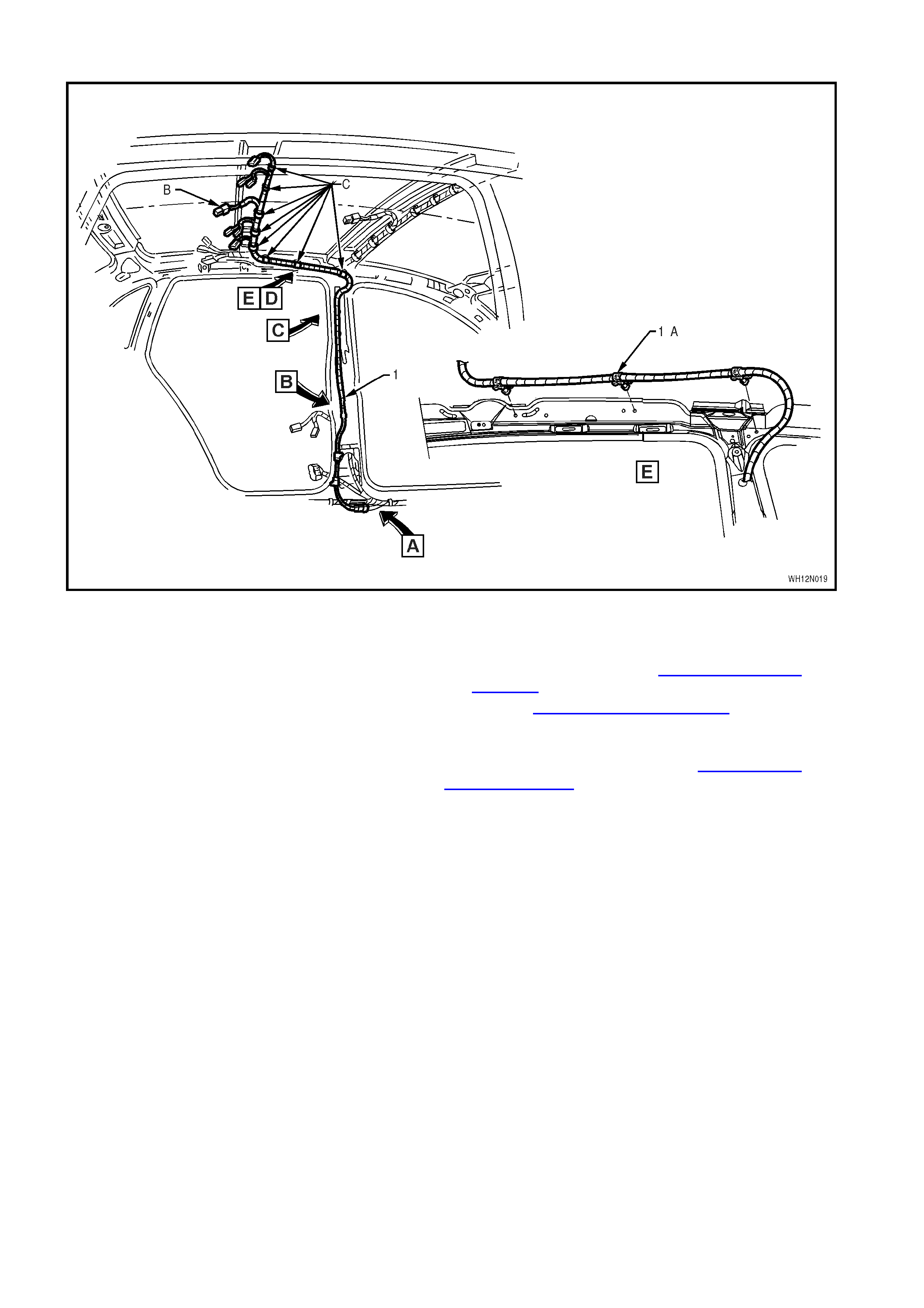
BODY WIRING HARNESS – 1 - INTERIOR - ALL MODELS
Legend
1. Rear Door Connector – Right Hand Side
2. Rear Door Jamb Switch Connectors – Right
Hand Side
3. Roof Harness (refer to ROOF WIRING
HARNESS – 1 diagram in this Section)
4. Front Door Connector – Right Hand Side
5. Front Door Jamb Switch Connectors – Right
Hand Side
6. Body Harness To Main Wiring Harness
Connectors
7. Body Harness To Power Window Switch And
Centre Console Harness Connectors
8. Body Wiring Harness
A. Clip bent over to retain body harness and fuel filler
door release cable (where applicable).
B. For continuation, refer to BODY WIRING HARNESS – 5
diagram in this Section.
C. This figure illustrates a Caprice Model.
D. Harness clipped to underbody, refer to BODY
WIRING HARNESS – 3 diagram in this Section.
A-A is one place
B-B is two places
For View A, refer to ROOF WIRING HARNESS –1
diagram in this Section.
For View B, refer to BODY WIRING HARNESS – 3
diagram in this Section.
For View C, refer to BODY WIRING HARNESS – 2
diagram in this Section.
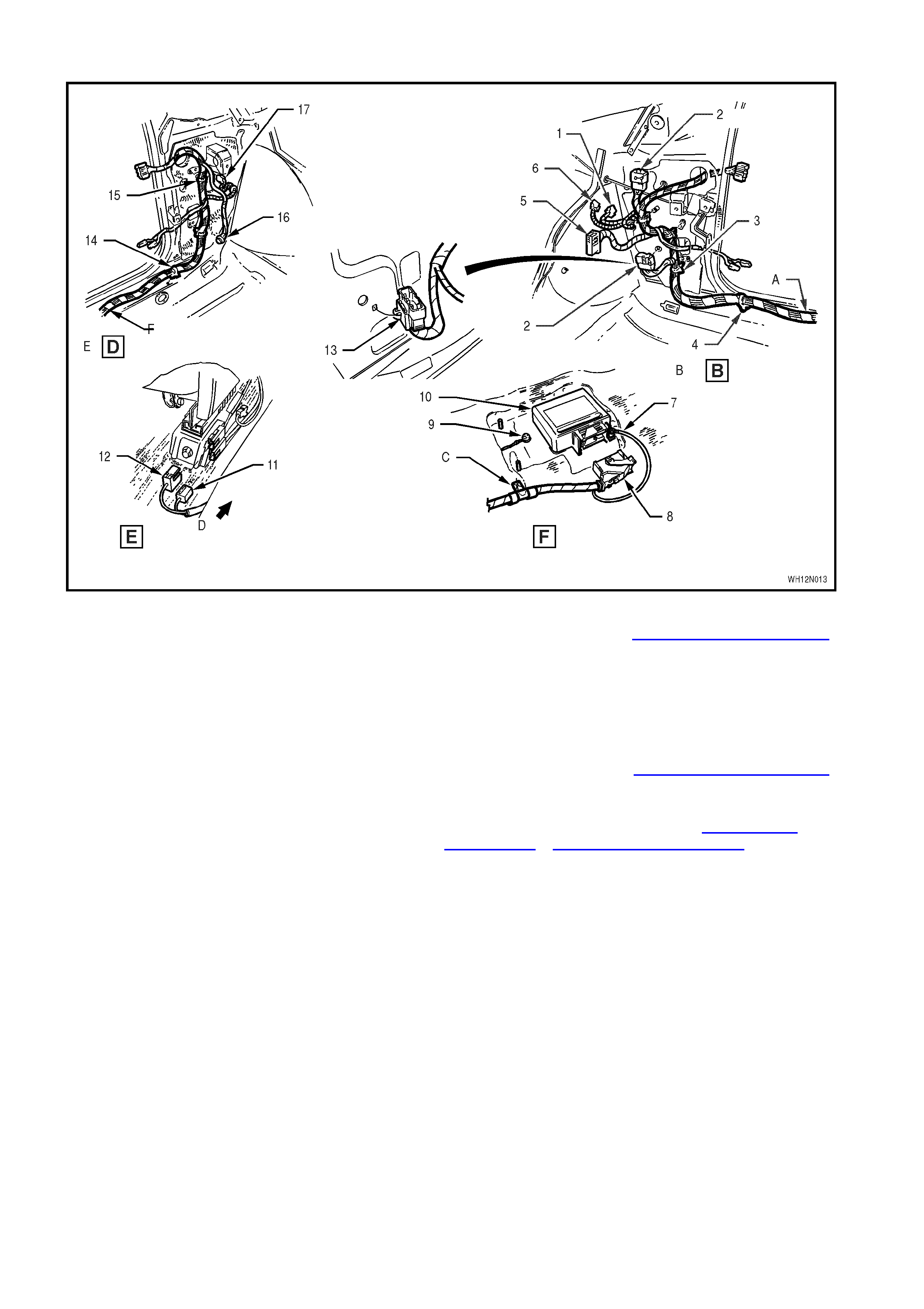
BODY WIRING HARNESS – 2 - INTERIOR - ALL MODELS
Legend
1. Roof Wiring Harness
2. Front Door Connector – Left Hand Side
3. Front Door Jamb Switch Connectors – Left
Hand Side
4. Harness Clipped to Underbody
5. Body Harness to Main Wiring Harness
Connectors
6. Body Wiring Harness
7. Rear Door Connector – Left Hand Side
8. Rear Door Jamb Switch Connectors – Left
Hand Side
9. Selt Belt Pre-Tensioners and Power Sear
Connectors
10. Main Wiring Harness to Selt Belt Pre-
Tensioner Connector
11. Power Window Switch Assembly
12. Centre Console Harness Connector
13. Handbrake Connector
14. Screw
A. Harness clipped to underbody in four places
For Views D, E & F, refer to BODY WIRING HARNESS – 3
diagram in this Section.
BODY WIRING HARNESS – 3 - INTERIOR - ALL MODELS
Legend
1. Turn Signal Connector – Right Hand Side
2. Body Harness To Main Wiring Harness
Connectors
3. Body Wiring Harness (attached shrould panel
in three places)
4. Body Harness Attached To Underbody (nine
places)
5. Body Control Module Connector
6. Power Antenna Connector
7. Air Bag Sensing & Diagnostic Module Earth
Lead
8. Air Bag Sensing & Diagnostic Module
Connector
9. Body Harness Earth
10. Air Bag Sensing & Diagnostic Module (SDM)
11. Selt Belt Pre-Tensioner Connector
12. Side Air Bag Module Connector
13. Body Harness to Main Wiring Harness
Connector (clipped to shoud side panel – two
places)
14. Body Harness Attached to Underbody (six
places)
15. Body Wiring Harness (attached shrould panel
in two places)
A. For continuaton, refer to BODY WIRING HARNESS – 1
diagram in this Section.
B. Figure illustrates the right hand side – Caprice
Model.
C. Body harness attached to stud as shown.
D. Front of vehicle.
E. Figure illustrates the left hand side – Caprice Model.
F. For continuation, refer to BODY WIRING HARNESS – 2
diagram in this Section.
For locaton of Views B, D, E & F, refer to BODY WIRING
HARNESS – 1 & BODY WIRING HARNESS – 2 diagram
in this Section.
16. Footwell Lamp Connector – Left Hand Side
17. Turn Signal Connector – Left Hand Side
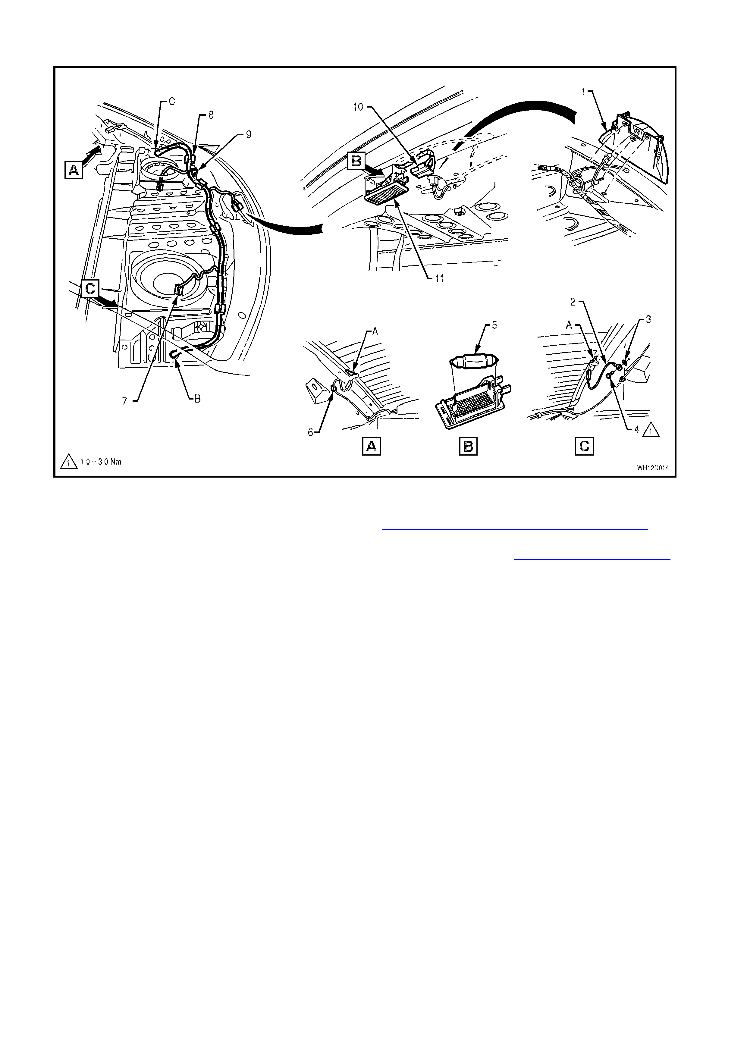
BODY WIRING HARNESS – 4 - PARCEL SHELF AND REAR COMPARTMENT LAMP - ALL MODELS
Legend
1. High Mounted Stop Lamp
2. Earth Lead
3. Washer
4. Screw
5. Globe
6. Heated Rear Window Lead
7. Rear Speaker Connector
8. Body Harness (clipped to rear seat upper panel
- seven places)
9. Back Panel Shelf Headphone Jack Connector
10. Rear Compartment Lamp Connectors
11. Rear Compartment Lamp Lens
A. For continuaton to subwoofer amplifier, refer to
DIVERSITY ANTENNA & AMPLIFIER WIRING
diagram in this Section.
B. For continuation, refer to BODY WIRING HARNESS – 5
diagram in this Section.
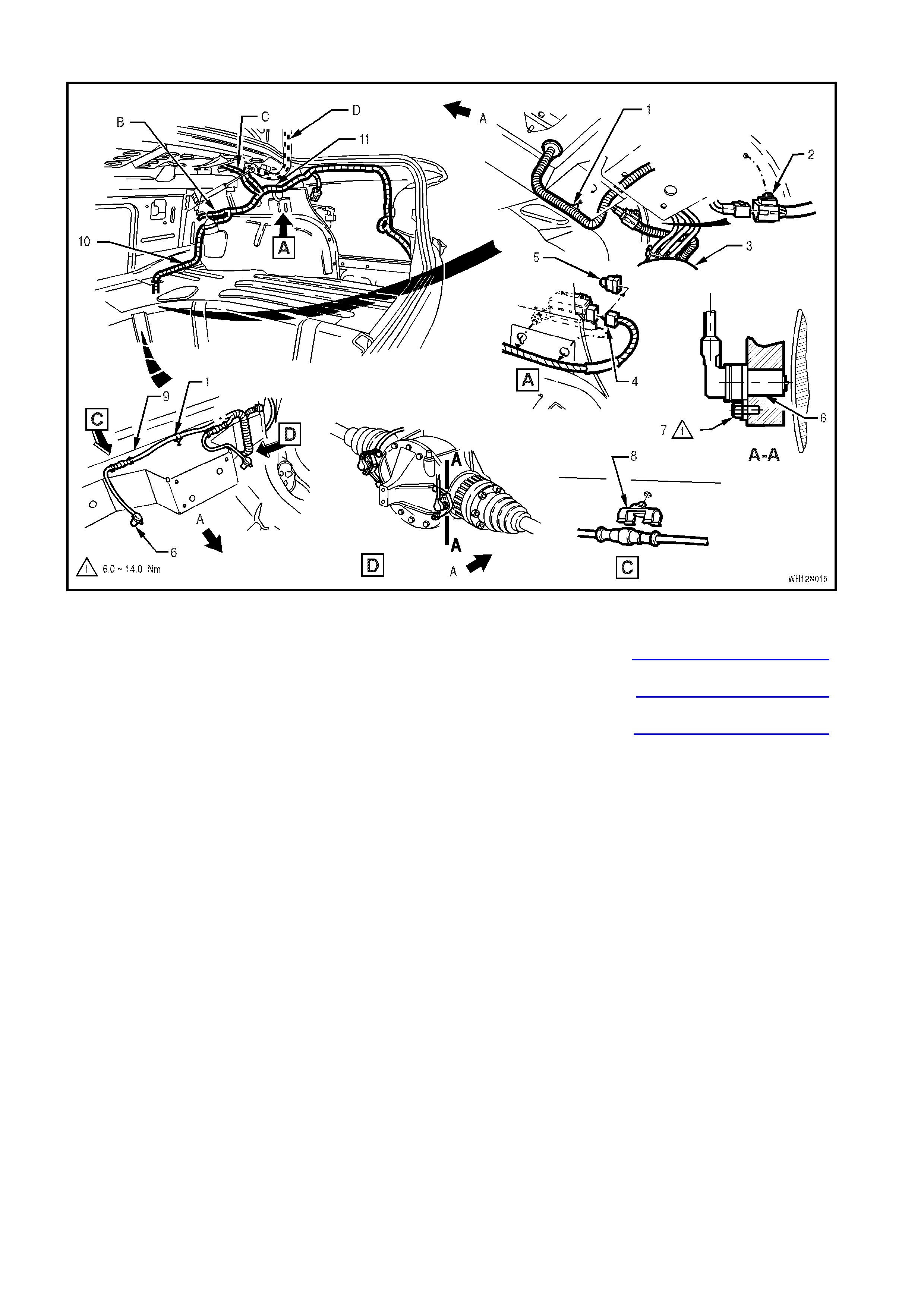
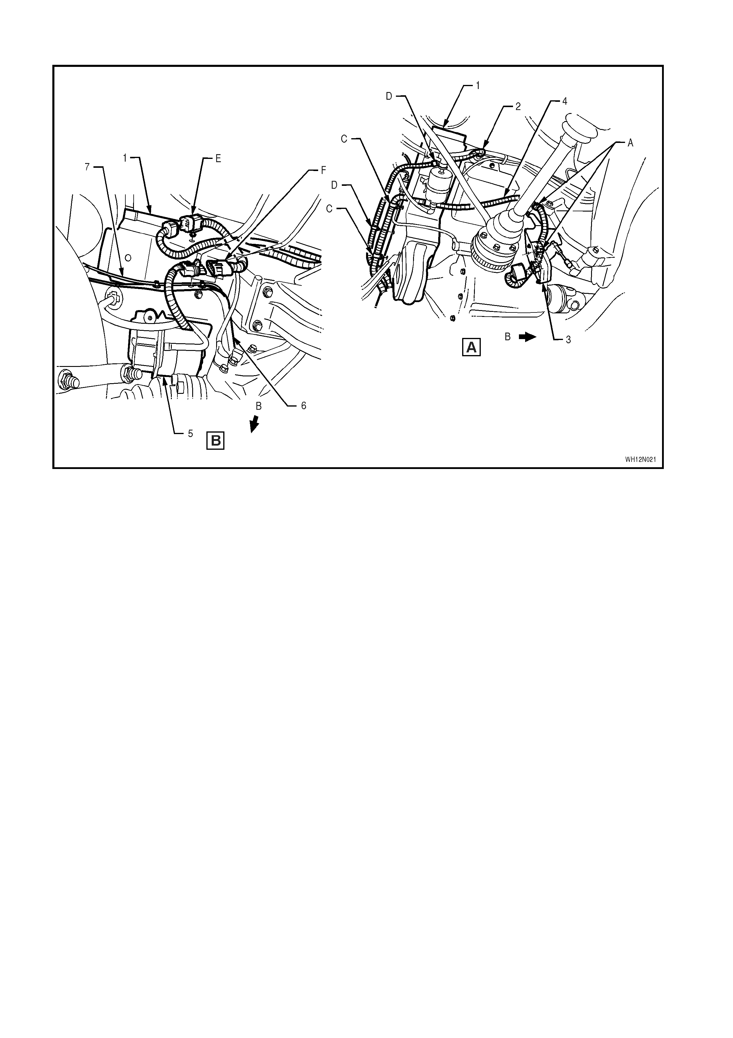
BODY WIRING HARNESS – 5 - REAR COMPARTMENT, FUEL TANK & ABS - ALL MODELS
Legend
1. Body Wiring Harness
2. Fuel Tank Harness Connector (clipped to rear
longitudinal extension)
3. Fuel Tank Assembly
4. Fuel Pump Speed Control Connector (vehicles
with V6 Supercharged enigne)
5. Bridge Connector (vehicles without V6
Supercharged engine)
6. Rear Wheel Speed Sensor
7. Retaining Screw
8. Retaining Clip (two places)
9. Rear Axle Crossmember
10. Harness clipped to Lower wheel house brace –
Right Hand Side
11. Harness clipped to Side Inner Panel
A. Front of vehicle.
B. For continuaton, refer to BODY WIRING HARNESS – 1
diagram in this Section.
C. For continuation, refer to BODY WIRING HARNESS – 4
in this Section.
D. For continuation, refer to BODY WIRING HARNESS – 6
diagram in this Section.
BODY WIRING HARNESS – 6 - REAR COMPARTMENT - ALL MODELS
Legend
1. Body Wiring Harness
2. Side Panel Outer
3. Back Panel Lower Reinforcement
4. Screw
5. Body Earth Lead
6. To Licience Plate Lamps
7. To Rear Quarter Lamps
8. Trailer Connector – Left Hand Side
9. Body Harness (clipped to back panel lower
reinforcement two places)
A. Clip bent to retain hareness
B. Typical view, four places
C. Right hand side shown
D. For continuation, refer to BODY WIRING HARNESS - 5
diagram in this Section.
Section A-A is two places.
BODY WIRING HARNESS – 7 - DECKLID - ALL MODELS
Legend
1. Right Hand Reverse/Tail Lamp Connector
2. Body Wiring Harness (clipped to decklid inner
– five places)
3. Body W iring Harness (clipped to decklid hinge
– four places)
4. Left Hand Rerverse/Tail Lamp Connector
5. Rear Compartment Lamp Switch Connector
6. Decklid Lock Actuator Connector
For views A, B, C and Sections A-A & B-B, refer to BODY
& ROOF WIRING HARNESSES – 10 diagram in this
Section.
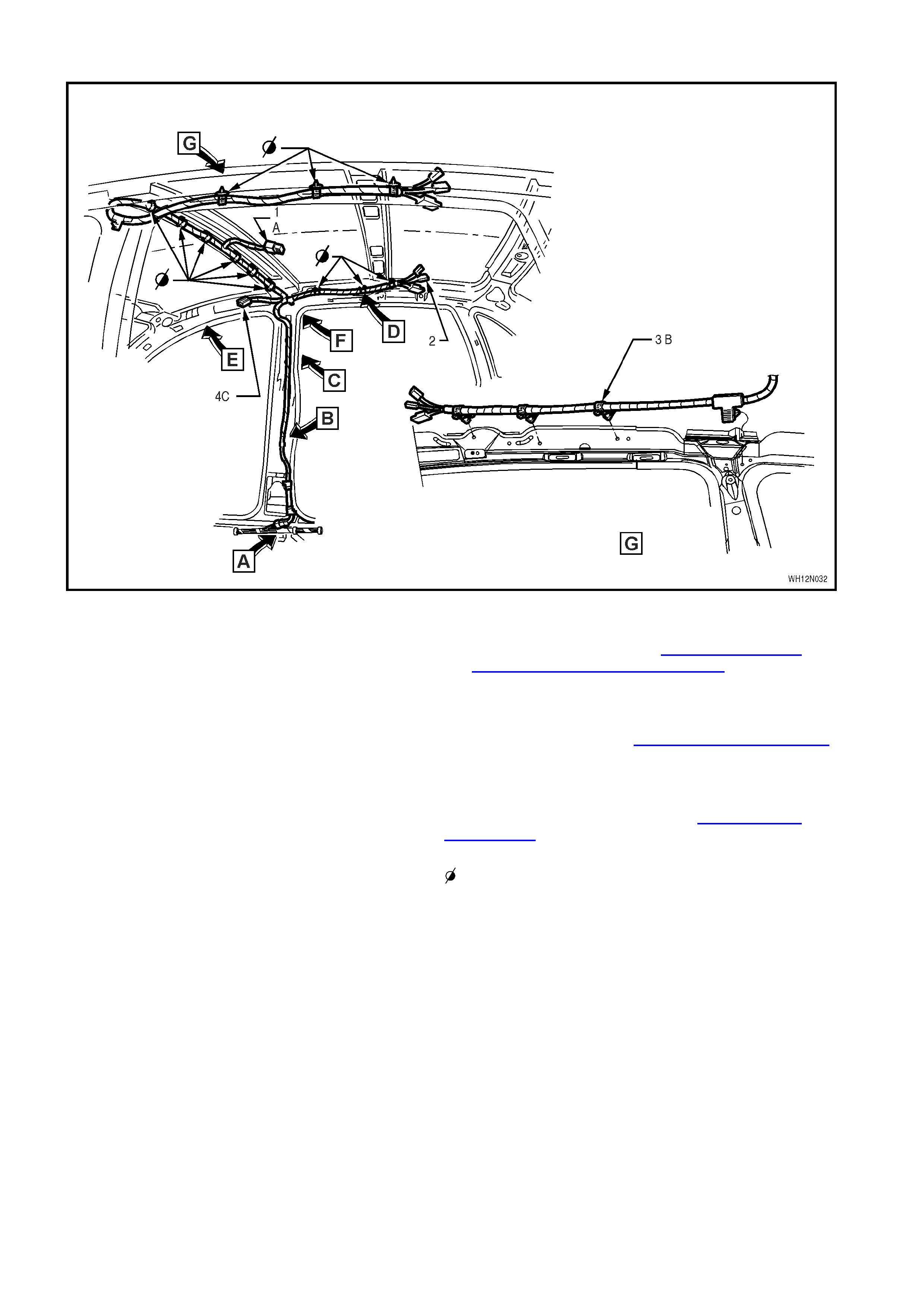
ROOF WIRING HARNESS – 1 - ROOF LAMPS – ALL MODELS
Legend
1. Dome Lamp Connector
2. Passenger Rear Compartment Lamp
Connector
3. Roof Wiring Harness
4. Sun Visor Lamp Connector
A. For continuation, refer to BODY & ROOF WIRING
HARNESSES – 5 diagram in Section 12N, FUSES,
RELAYS AND WIRING HARNESSES of the VT
Series I Service Information.
B. Harness attached to inner side panel as shown
(three places).
C. For continuation, refer to ROOF WIRING HARNESS – 2
diagram in this Section.
For Views A through F, refer to ROOF WIRING
HARNESS – 2 diagram in this Section.
Wiring harness retainers.
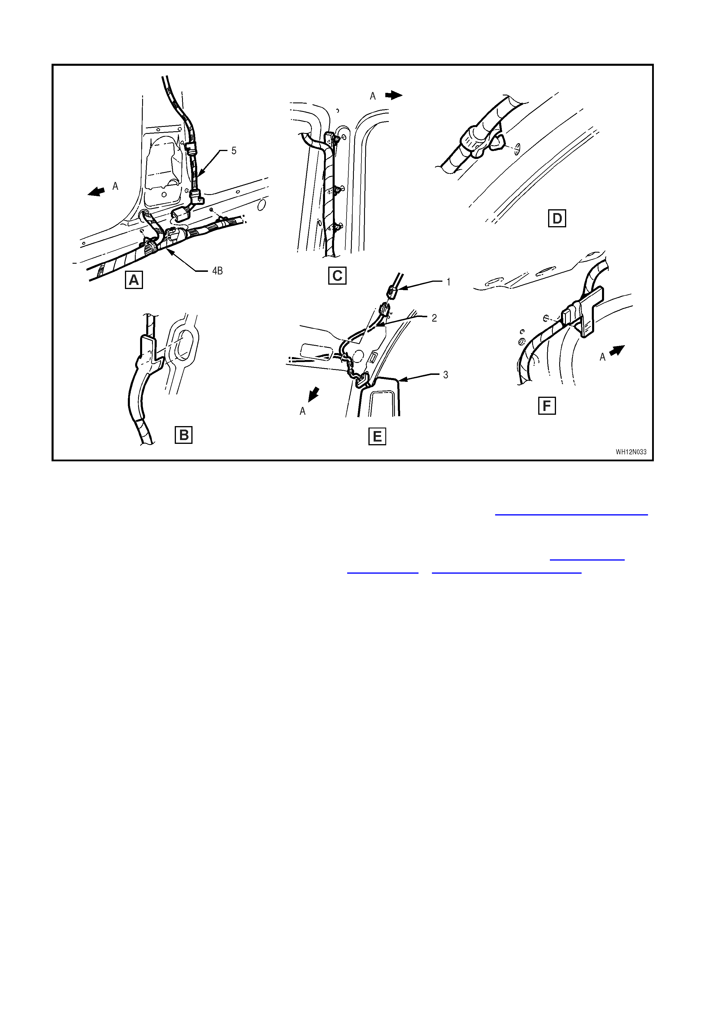
ROOF WIRING HARNESS – 2 - INTERIOR – ALL MODELS
Legend
1. Roof Harness Connector
2. Sun Visor Illumination Harness (part of roof
headlining assembly)
3. Sun Visor
4. Body Wiring Harness
5. Roof Wiring Harness
A. Front of vehicle.
B. For continuation, refer to BODY WIRING HARNESS – 1
diagram in this Section.
For location of Views A though F, refer to ROOF WIRING
HARNESS – 1 & ROOF WIRING HARNESS – 3 diagrams
in this Section.
ROOF WIRING HARNESS – 3 - AUDIO REAR REMOTE - CAPRICE
Legend
1. Rear Remote Wiring Harness A. Harness attached to inner side panel as shown –
three places.
B. For continuation, refer to Section 12D AUDIO
SYSTEMS of this VT Series II Service Information.
C. Refer to ROOF WIRING HARNESS – 2 diagram in
this Section.
For Views A through D, refer to ROOF WIRING
HARNESS – 2 diagram in this Section.
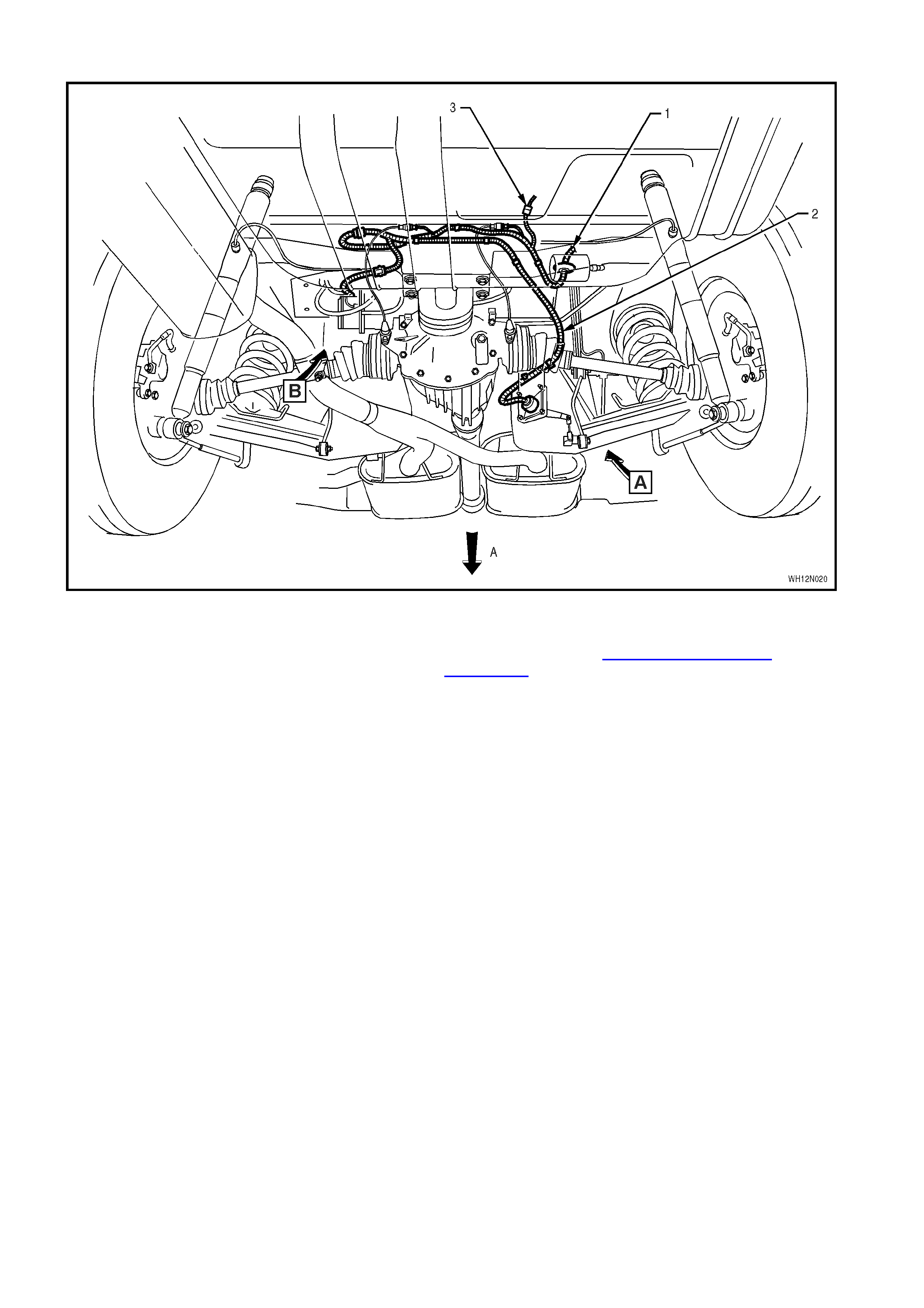
AUTOMATIC LEVEL RIDE HARNESS – 2 - ALL MODELS
Legend
1. Rear Axle Crossmember
2. Body Wiring Harness
3. Height Sensor Assembly
4. Automatic Level Ride Harness
5. Compressor Assembly
6. Automatic Level Ride Bracket
7. Air Lines
A. Harness clipped to height sensor bracket.
B. Front of vehicle.
C. Automatic level ride harness clipped to rear axle
crossmember – three places.
D. Body wiring harness clipped to rear axle crossember
– two places.
E. Automatic level ride harness connector clipped to
rear axle crossmember.
F. Automatic level ride harness connector clipped to
automatic level ride bracket.
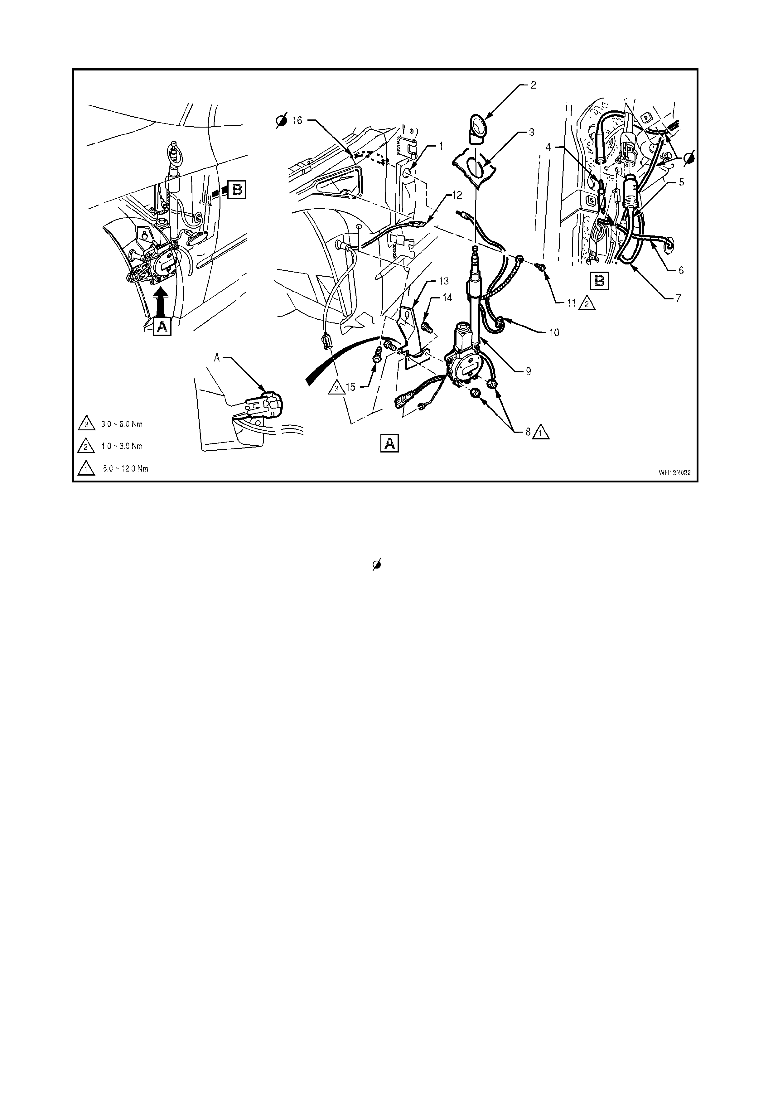
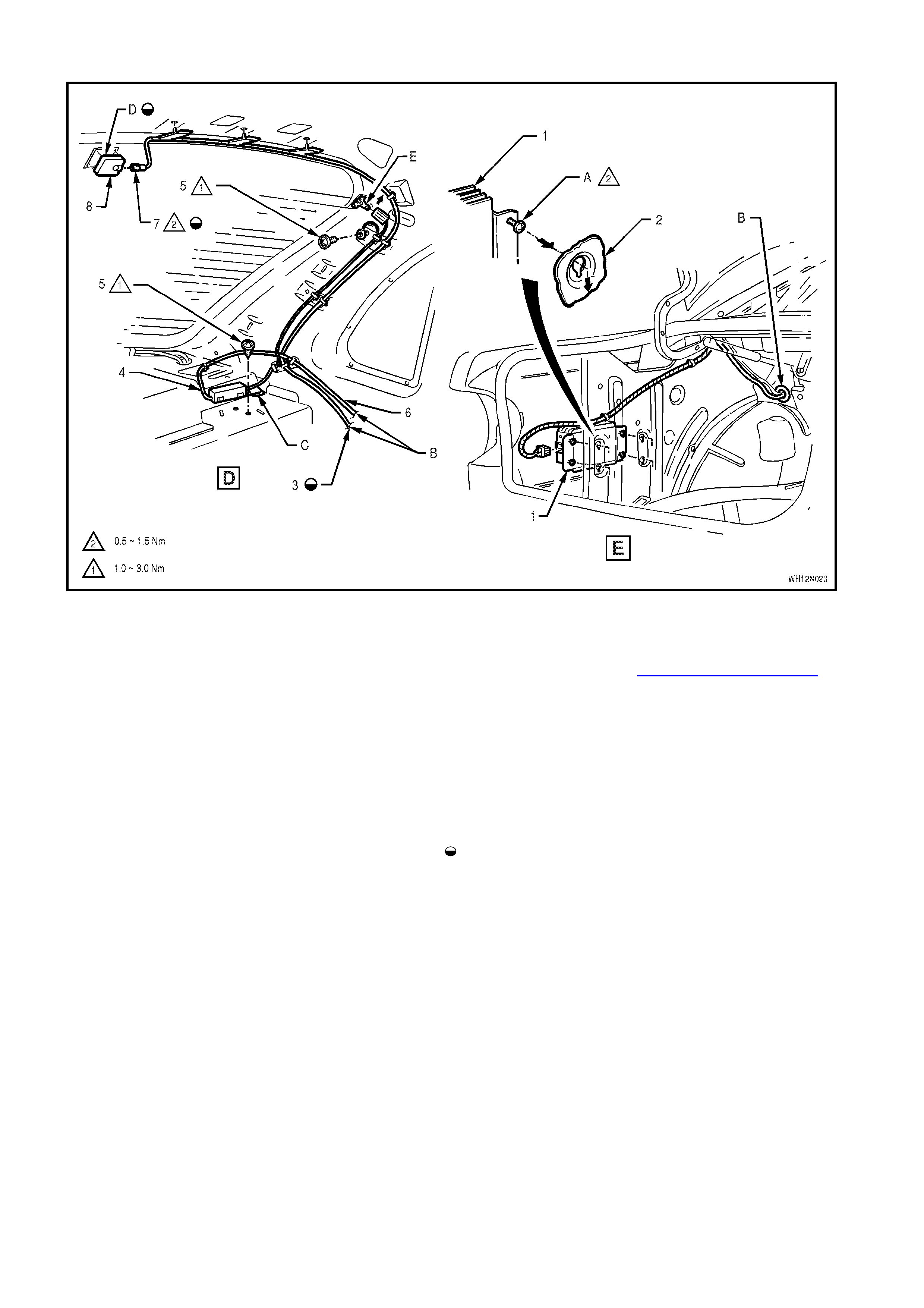
POWER ANTENNA - ALL MODELS
Legend
1. Antenna Lead Hole 2. Bezel
3. Antenna Exit Hole
4. Diversity Antenna Lead Connector
5. CD Harness
6. Body Wiring Harness
7. Excess Length of Antenna Lead Routed
Behind Body Wiring Harness
8. Nuts
9. Power Antenna
10. Antenna Lead Hole Sealing Plug
11. Screw
12. Side Repeater Lamp Connector
13. Support Brace
14. Bolt (two places)
15. Screw
16. Antenna Lead
A. Ensure connector fits firmly onto brace tab as
shown.
Antenna lead
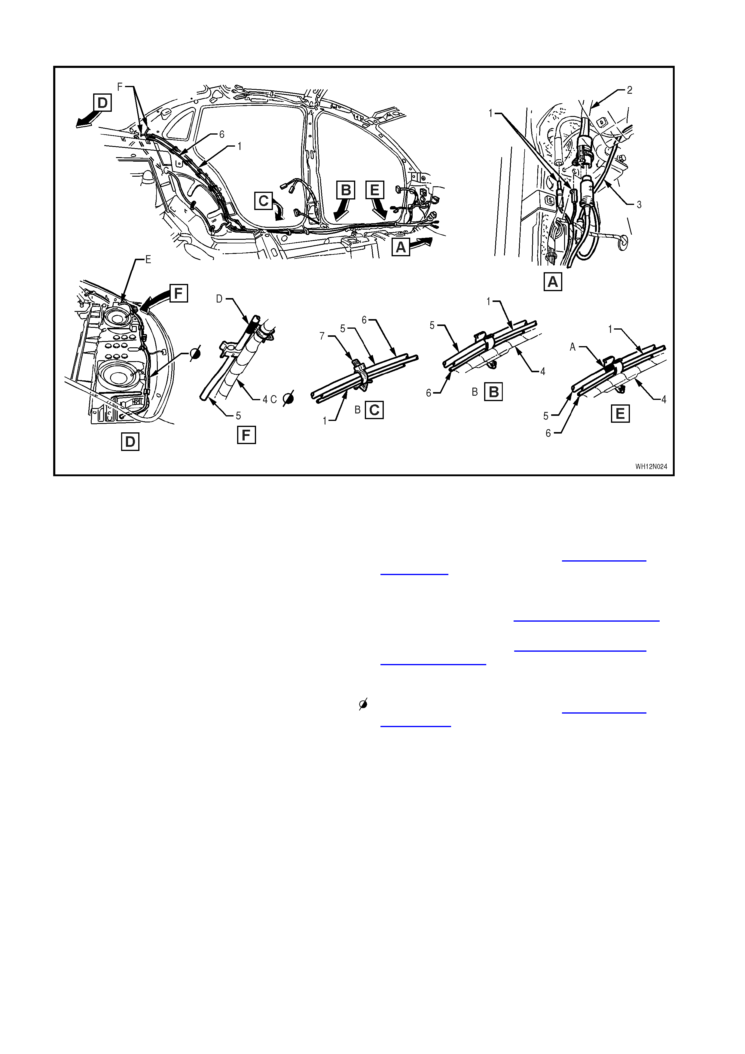
ANTENNA & DIVERSITY ANTENNA LEAD EXTENSIONS - ALL MODELS
Legend
1. Clip
2. Antenna Connector
3. Diversity Antenna Connector
4. Diversity Antenna Lead Extension
5. Antenna Lead Extension
A. Clips are located on either side of dimples on lower
left side rail as shown.
B. White marks on antenna leads to be in line with
middle clip.
C. For continuation, refer to View C in this diagram.
D. Connectors installed to radio then cables secured
by bent over tab as shown.
E. For continuation, refer to DIVERSITY ANTENNA &
AMPLIFIER WIRING diagram in this Section.
F. For continuation, refer to POWER ANTENNA
diagram in this Section.
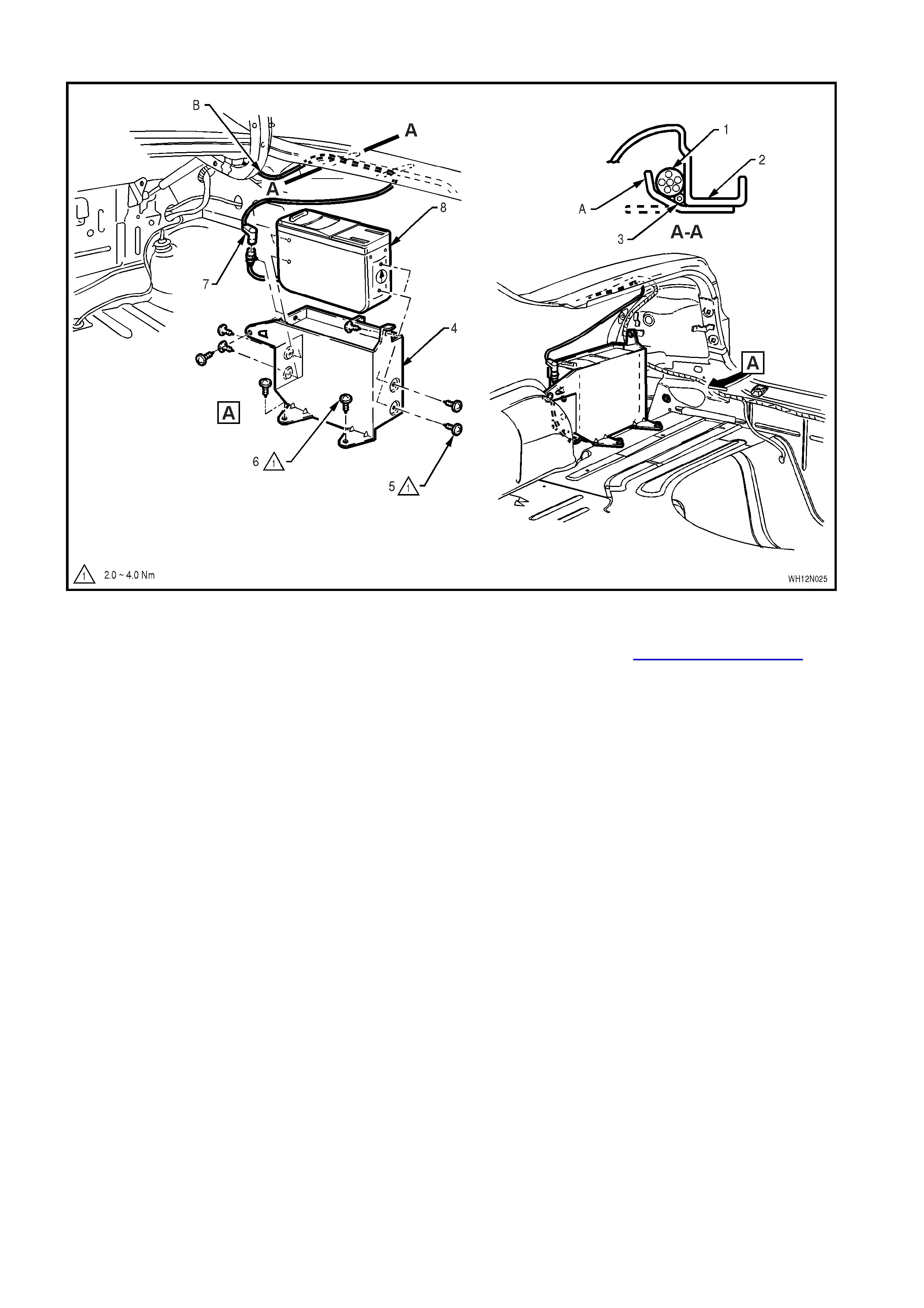
DIVERSITY ANTENNA & AMPLIFIER WIRING - ALL MODELS
Legend
1. Amplifier
2. Side Panel Inner
3. Mobile Phone Antenna Lead
4. Diversity Antenna
5. Screw
6. Diversity Antenna Lead
7. Mobile Phone Antenna Lead Connector
8. Mobile Phone Antenna Base Assembly
A. Amplifier is installed in direction of arrows shown
(four places).
B. For continuation, refer to CD CHANGER WIRING – 1
diagram in this Section.
C. Tab located in slot as shown.
D. To install base assembly, wipe window using prepsol
solvent and remove backing paper before adhereing
base to rear window as shown. Then connect
antenna lead to base.
E. Tab bent over after installation of diversity antenna
connector in direction shown.
Mobile telephone antenna assembly.
CD CHANGER WIRING – 1 - ALL MODELS
Legend
1. Diversity Antenna Lead
2. Main Wiring Harness
3. Power Antenna Lead
4. Body Wiring Harness
5. CD Harness
6. Mobile Phone Antenna Lead
7. Strap
A. White tape mark on CD harness aligned with forward
most clip.
B. Two places.
C. Body wiring harness, refer to ROOF WIRING
HARNESS- 2 diagram in this Section.
D. White tape mark on CD harness aligned with cable
clip as shown.
E. For continuation, refer to CD CHANGER WIRING – 2
diagram in this Section.
F. For continuation, refer to DIVERSITY ANTENNA &
AMPLIFIER WIRING diagram in this Section.
Body wiring harness, refer to ROOF WIRING
HARNESS –2 diagram in this Section.
CD CHANGER WIRING – 2 - ALL MODELS
Legend
1. Body Wiring Harness
2. Side Panel Outer
3. CD Harness
4. CD Changer Unit Mounting Bracket
5. CD Changer Unit To Mounting Bracket Theft
Deterrent Screws (four places)
6. Mounting Bracket Base Theft Deterrent Screws
(four places)
7. CD Harness Connection to CD Changer Unit
A. Clip bent to retain harness.
B. For continuation, refer to CD CHANGER WIRING –2
diagram in this Section.
SRS WIRING - ALL MODELS
Legend
1. Air bag Sensing & Diagnostic Module Mounting
Screw (three places)
2. Air bag Sensing & Diagnostic Module (SDM)
3. Earth Terminal
4. Peripheral Acceleration (Side) Sensor and
Bracket Assembly
5. Lower “B” Pillar
6. Air bag Sensing & Diagnostic Module Connector
A. For continuation, refer to BODY WIRING HARNESS – 2
diagram in this Section.
B. For continuation, refer to MAIN WIRING HARNESS- 8
diagram in this Section.
C. Front of vehicle.
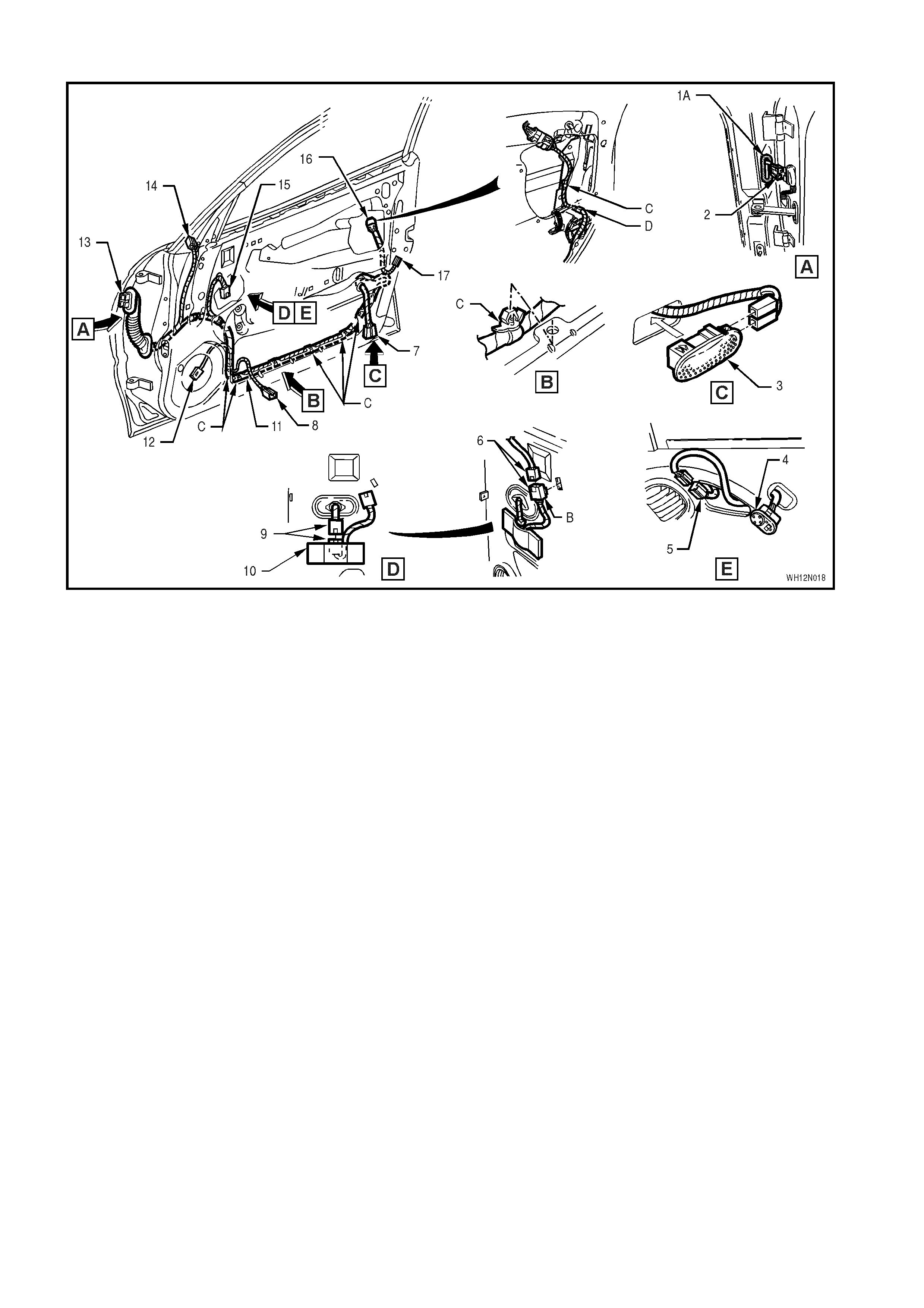
FRONT DOOR WIRING HARNESS - ALL MODELS
Legend
1. Gasket
2. Body Wiring Harness
3. Door Courtesy Lamp
4. Exterior Rear Vision Mirror Control Switch
5. Mirror Control Switch Connector
6. Mirror Switch to Switch Module Connectors
7. Courtesy Lamp Connector
8. Window Lifter Motor Connector
9. Front Door Harness Connector to Mirror Switch
Module Assembly
10. Mirror Switch Module Assembly
11. Front Door Harness
12. Door Speaker Connector
13. Body Harness Connector
14. Exterior Rear Vision Mirror Connector
15. Mirror Switch Module Connector
16. Door Lock Switch Connector (Driver’s Side
Only)
17. Door Lock Actuator Connector
A. Gasket located around slot in door opening frame at
A pillar location.
B. Mirror control switch connector clipped to door inner
panel as shown.
C. Door harness clipped to door inner panel as shown.
D. Ensure harness is routed behind window guide
piece.