
SECTION 12Q - TELEMATICS
IMPORTANT:
Before performing any Service Operation or other procedure described in this Section, refer to Section 00
CAUTIONS AND NOTES for correct workshop practices with regard to safety and/or property damage.
1. GENERAL INFORMAT ION
The telematics module us e d in the WH Series Stat es man and Capr ic e models is the same module as use d in the
VX Series of vehicles.
For all telematics information refer to Section 12Q TELEMATICS of the VX Service Information. However the
installation of the telematics module is specific to the WH series of vehicle.
Techline
Techline
Techline
Techline
Techline
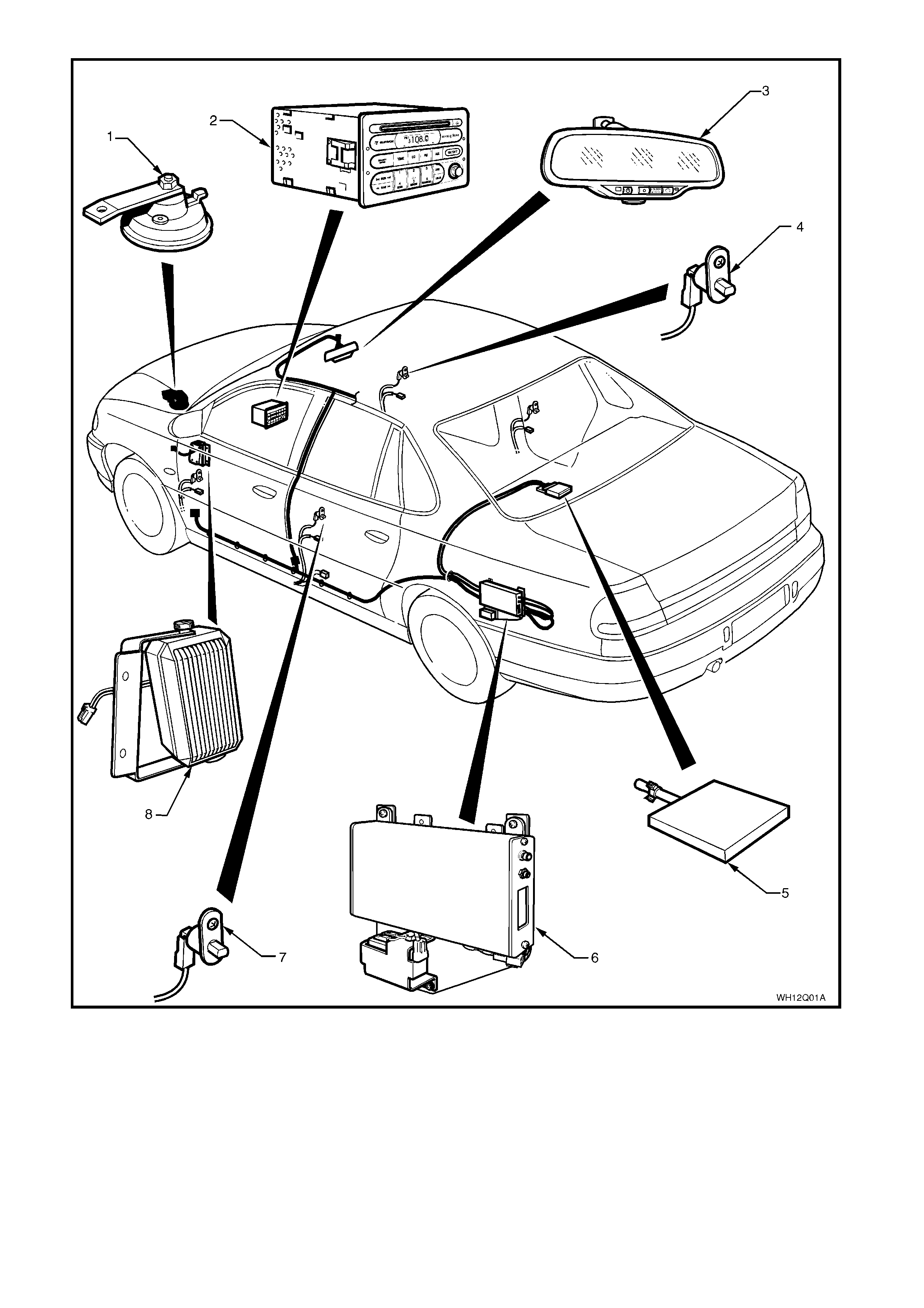
Figure 12Q-1
1. Theft deterrent horn 4. Driver’s door jamb switch 7. Passenger door jamb switches
2. Radio 5. Telematics antenna 8. Telematics speaker
3. Interior rear view mirror 6. Telematics module assembly

1.1 WIRING HARNESSES
WH Series vehicles equipped with the telematics system have specific main and body harnesses, and a
telematic s patc h harnes s. T he telem atics patch harne ss c onnector 2 ( YB178) pl ugs into the m ain har ness b ehind
the left hand kick panel trim (view D) and the telem atics patch harness connecto r 1 (YB177) plugs into the body
harness at the bottom of the B pillar (view C). The telematics patch harness is also connected to the telematics
module (YR55) (view B), the interior rear view mirror (YB186) (view G). The telematics speaker (view F) is
connected to the main harness connector (YB181).
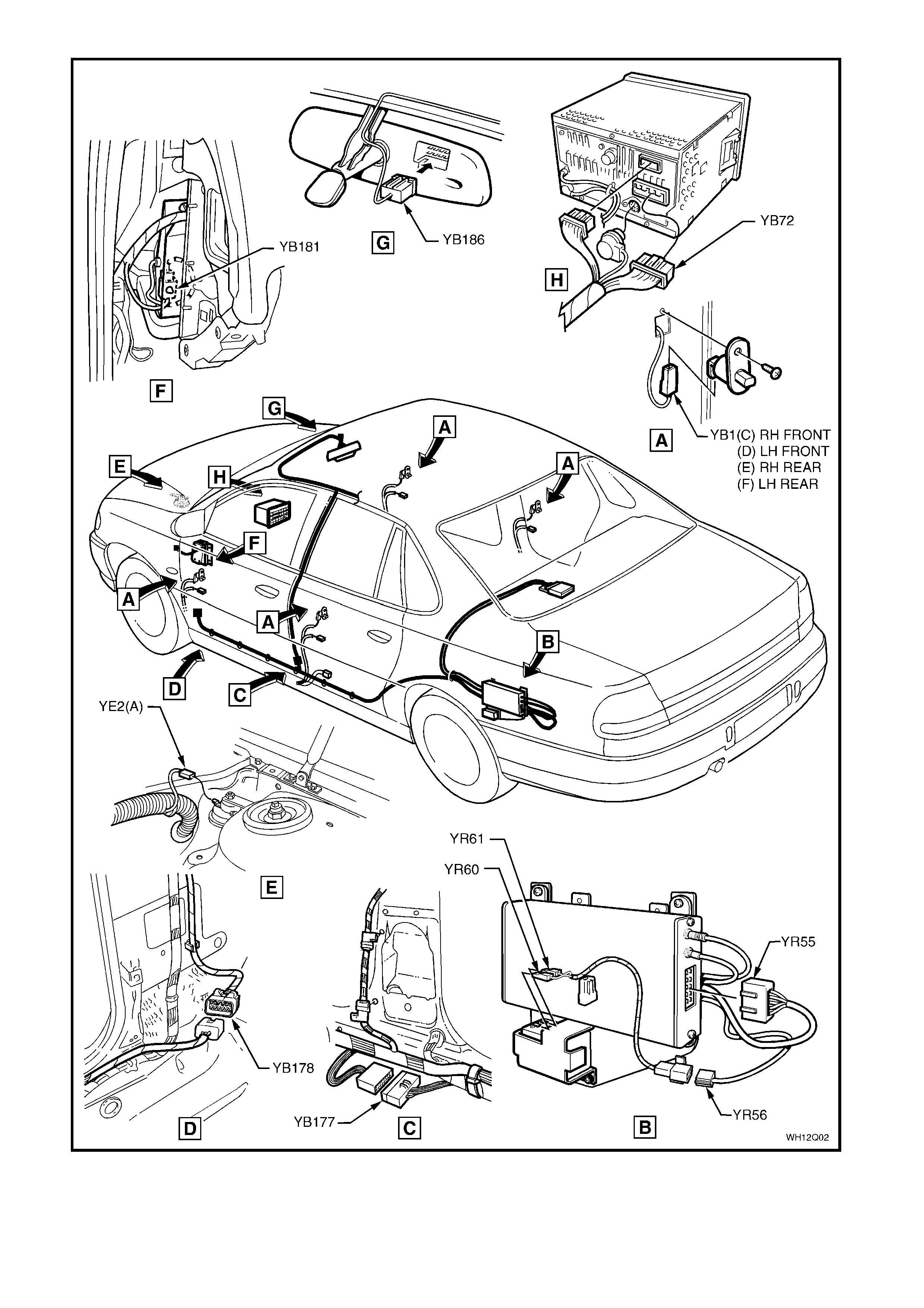
Figure 12Q-2
2. SERVICE OPERATIONS
When carr yin g ou t any serv ice p rocedu r e on th e v ehicle that involv es disco nn ectin g t he b att ery cable s o r
any procedure that may cause the battery voltage to fall below 12 Volts, the telematics module Service
Mode MUST BE ENABLED. Refer to 4.3 TECH 2 TEST MODES F4: Program, F2 Operating Mode,
F1: Service Mode in Section 12Q Telematics of the VX Series Service Information.
If the telematics module service mode is not enabled, a “Batter y Remov al Alert” will be tr ansmitted to the
Holden Assist Centre whenever the battery is disconnected, or a “Low Battery Voltage Alert” when the
battery voltage is low.
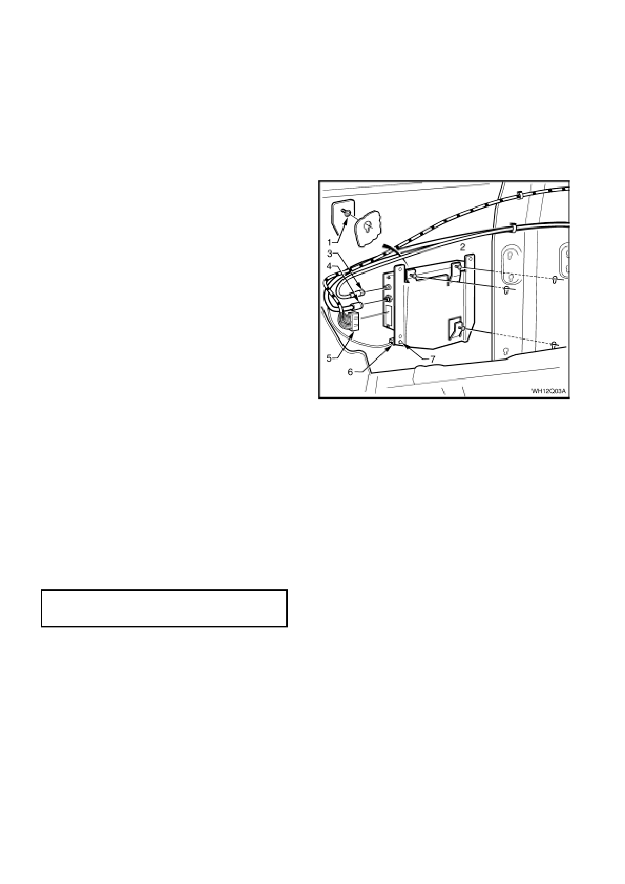
2.1 TELEMATICS MODULE ASSEMBLY
REMOVE
1. Using Tech 2, enable the telematics module
service mode. Refer to 4.3 TECH 2 TEST
MODES F4: Program, F2: Operating Mode,
F1: Service M ode in S ec tio n 12Q Telematic s of
the VX Series Service Information.
2. Disconnect the negative battery cable from the
battery.
3. Remove the left side rear compartment
wheelhouse carpet, refer to Section 1A1
BODY in this Service Information.
4. Remove the subwoofer amplifier refer
Section 12D in this Ser v ic e Information.
5. Disconnect telematics module harness
connector (5), GPS antenna connector (3),
GSM antenna connector (4), and the backup
battery harness connector (6).
6. Remove the backup battery harness retaining
clip (7) from the mounting bracket.
7. Loosen the four telematics module assembly
retaining screws (1).
8. Slide the contr ol module u pward to re lease the
screw heads from the slots in the side inner
panel and remove telematics module
assembly.
Figure 12Q-3
REINST ALL
1. Reverse of the removal, noting the following.
2. Tighten the telematics module assembly
retaining screws to the correct torque
specification.
TELEMATICS MODULE ASSEMBLY
RETAINING SCREWS 3 – 3.5 Nm
TORQUE SPECIFICATION
3. Use Tech 2 to disable the telematics module
Service Mode. Refer to 4.3 TECH 2 TEST
MODES F4: Program, F2: Operating Mode,
F1: Service M ode in S ec tio n 12Q Telematic s of
the VX Series Service Information.
NOTE: If the telematics module service mode is
not disabled, the system will not have full
functionality.
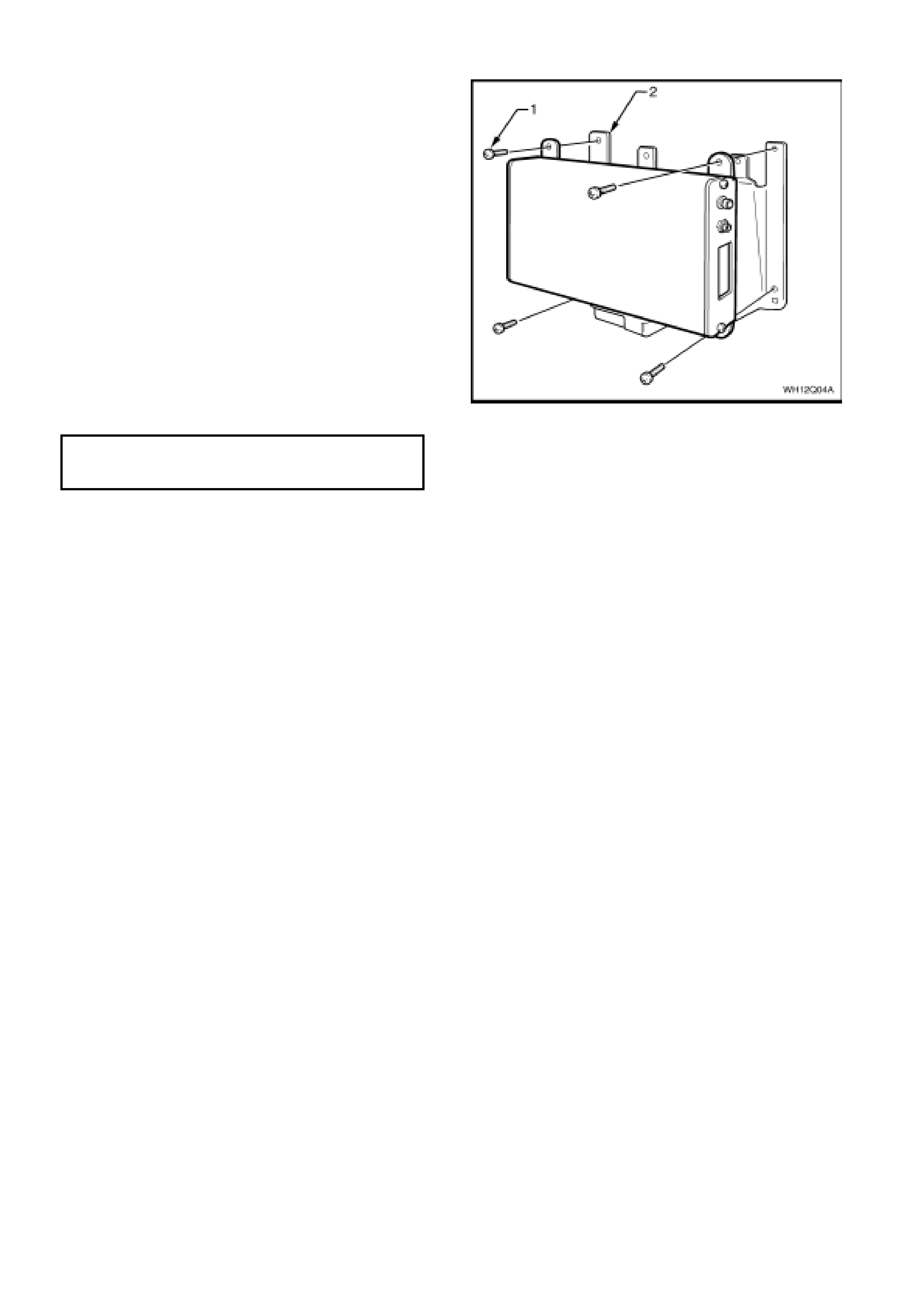
2.2 TELEMATICS MODULE
REMOVE
1. Using Tech 2, enable the telematics module
service mode. Refer to 4.3 TECH 2 TEST
MODES F4: Program, F2: Operating Mode,
F1: Service Mode in Section 12Q Telematics
of the VX Series Service Information.
2. Remove the telematics module assembly.
Refer 3.1 TELEMATICS MODULE
ASSEMBLY in this Section
3. Remove the four telematics module to
mounting bracket retaining screws (1) and
remove the telematics module from the
mounting plate (2).
REINST ALL
1. Reverse of the removal, noting the following.
2. Tighten the te lematics m odule retaini ng sc r e ws
to the correct torque specification.
TELEMATICS MODULE TO MOUNTING
BRACKET RETAINING SCREWS 3 – 3.5 Nm
TORQUE SPECIFICATION
3. Use Tech 2 to disable the telematics module
service mode. Refer to 4.3 TECH 2 TEST
MODES F4: Program, F2: Operating Mode,
F1: Service Mode in Section 12Q Telematics
of the VX Series Service Information.
NOTE: If the telematics module service mode is
not disabled, the system will not have full
functionality.
Figure 12Q-4
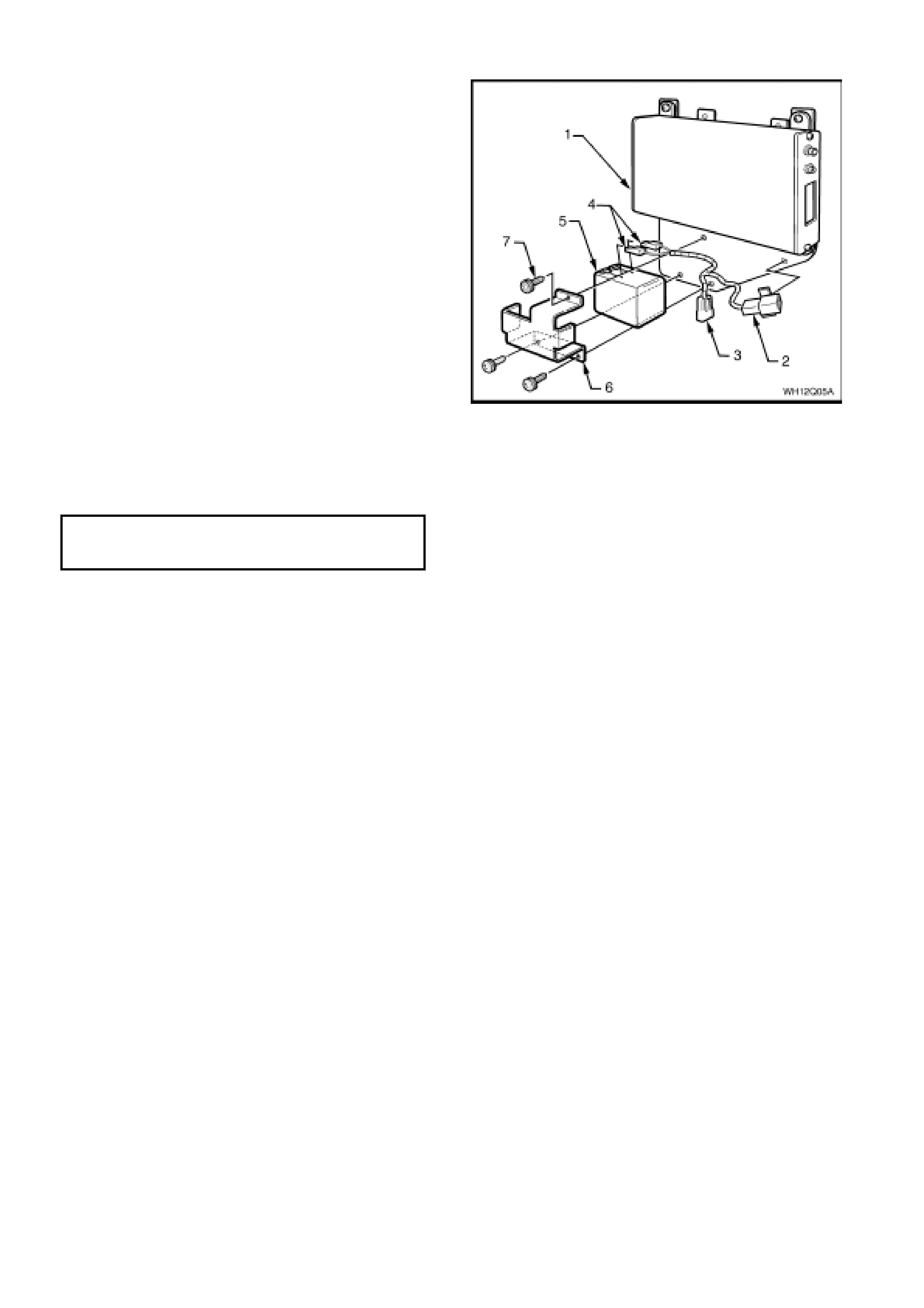
2.3 BACKUP BATTERY
REMOVE
1. Using Tech 2, enable the telematics module
service mode. Refer to 4.3 TECH 2 TEST
MODES F4: Program, F2: Operating Mode,
F1: Service M ode in S ec tio n 12Q Telematic s of
the VX Series Service Information.
2. Remove the telematics module assembly.
Refer 3.1 TELEMATICS MODULE
ASSEMBLY in this Section
3. Disconnect the two backup battery terminals
(4) from the backup battery (5).
4. Remove the six backup battery bracket (6)
retaining screws (7) and remove the backup
battery.
Figure 12Q-5
REINST ALL
1. Reverse of the removal noting the following.
2. Tighten backup battery retaining screws to the
correct torque specification.
TELEMATICS BACKUP BATTERY
RETAINING SCREWS 3 – 3.5 Nm
TORQUE SPECIFICATION
3. Use Tech 2 to disable the telematics module
Service Mode. Refer to 4.3 TECH 2 TEST
MODES F4: Program, F2: Operating Mode,
F1: Service M ode in S ec tio n 12Q Telematic s of
the VX Series Service Information.
NOTE: If the telematics module service mode is
not disabled, the system will not have full
functionality.
