
SECTION 1A1 - BODY
IMPORTANT
Before performing any Service Operation or other procedure described in this Section, refer to
Section 00 CAUTIONS AND NOTES for correct workshop practices with regard to safety and/or
property damage.
1. GENERAL DESCRI PTI O N
The WH Series Statesman and Caprice is a completely new vehicle design. Sheetmetal, interior trim, air
conditioning, and lighting systems have been redesigned. Bumper facias complement the new styling and
accommodate below bumper engine cooling entry. Head, turn signal and rear lamps are modified to suit
design changes.
Techline

2. SERVICE OPERATIONS
2.1 PLASTIC COMPONENT LOCATIONS
Plastic components are used throughout the vehicle. To assist with the identification and composition of
those components refer to the following chart.
PLASTIC COMPONENT LOCATIONS
COMPONENT CODE PLASTIC TYPE
Radiator grille ABS Acrylonitrile Butadiene Styrene
Front Bumper Bar TPO Thermoplastic Olefin
Rear Bumper Bar TPO Thermoplastic Olefin
Air Baffle PP Polypropylene
Fender Liner TPO Thermoplastic Olefin
Front Turn Signal Lamp PMMA Polymethyl Methacrylate
Plenum Chamber Cover ASA Acrylate Styrene Acrylonitrile
Door Airbox PPE Polypropylene Ether
Coolant Reservoir PP Polypropylene
Cooling Fan Shroud PP Polypropylene
Instrument Panel Pad PU PVC/ASA Skin, Polyurethane Foam
Console ABS Acrylonitrile Butadiene Styrene
Shroud Lower Trim Assembly PP Polypropylene
Front Pillar Garnish PPE Polypropylene Ether
Centre Pillar - Upper Trim Assembly ABS Acrylonitrile Butadiene Styrene
Centre Pillar - Lower Trim Assembly ABS Acrylonitrile Butadiene Styrene
Quarter Window Inner Trim Assembly ABS Acrylonitrile Butadiene Styrene
Rocker Panel Cover PP Polypropy lene
Heater Case PP Polypropylene
Rear Tail lamp PMMA Poly methyl Methacrylate
Rear Compartment Lid Lamp Assembly ABS Acrylonitrile Butadiene Styrene
Licence Plate Lamp Assembly PC Poycarbonate
Wheel Covers ABS/PC Acrylonitrile Butadiene Styrene/Poycarbonate
Body Side Mouldings PVC Polyvinylchloride (Vinyl)
Fuel Filler Door PPE/PA Polyphenylene/Polyamide
Glove Box ABS Acrylonitrile Butadiene Styrene
Centre Facia ABS Acrylonitrile Butadiene Styrene
Rocker Panel Skirts TPO Thermoplastic Olefin

2.2 BODY SHELL PARTS REPLACEMENT
When replacing or repairing a part or sub-assembly, care must be taken to ensure that correct alignment
and strength of unit as a whole is maintained. In some instances, major damage to the body or frame can
be more effectively and economically repaired by replacing a part or sub-assembly with a new one, rather
than repairing the damaged part.
Spot welding is used extensively for joining panels together, particularly around the flanged edges of dash
panel, windshield and back window openings, along edges of rocker panels and lower edge of the rear
body.
When replacing a section that is normally attached by this method and spot-welding equipment is not
available, or the location of the parts restricts access, the part or assembly should be attached by the
welding method known as ‘Plug Welding’, which is as follows:
1. Remove the damaged part by cutting through the spot welds between the panels with a thin-edged
chisel or by drilling the spot welds.
2. Drill eight mm diameter holes in either the new or mating part to correspond with the spacing and
location of the original spot welds. Parts to be drilled are determined by accessibility for the following
operations.
3. Clamp the new part in position and gas or arc weld the two parts together through each hole, finally
dressing off any high spots on exposed surfaces.
When replacing parts such as roof panels, rear quarter or rocker panels; where a butt or overlap weld is
required, the joint of the panels must be formed below the normal contour. This allows for filling over the
join and eliminates the possible reduction of sheet metal thickness following the necessary buffing or
grinding of a normal welding operation.
IMPORTANT: Following replacement or repair of body components, it is essential that effective rust
proofing techniques, as outlined in the following paragraphs, be observed.

2.3 ANTI-CORROSIVE TREATMENT
Precoated and galvanised steel is used extensively for various body panels for increased corrosion
protection of the body. Body panels such as the door and rear compartment lid outer panels are precoated
on the inner surface of the metal to improve corrosion protection. Other body structure members have
complete double sided galvanised protection.
In addition, a rust preventative material is sprayed after paint application to areas such as interior surfaces
of doors, etc.
Any repair or replacement of panels, assemblies, etc., that disturb this anti-corrosive treatment must be
resealed and should be included as part of the repair or replacement operation.
Anti-corrosive compounds used for repairs should be light bodied materials designed to penetrate between
metal-to-metal surfaces such as pinch weld flanges and integral panel attaching points.
All bare metal surfaces must be treated with metal conditioner and primed. These operations need to be
carried out prior to the application of sealers, waxes and sound deadeners. Attaching points of new
replacement panels should be resealed. The hemming flanges of replacement doors, tailgates and rear
compartment lids will require resealing.
Open joins which require bridging of the sealer to close a gap should be sealed with a heavy bodied
caulking material. When colour application is required to restore repaired areas to original appearance,
conventional refinishing preparation, undercoat build-up and colour application techniques should be
employed.
When deadeners are disturbed during damage repair, or a panel has been replaced, the deadener material
must be replaced with an equivalent material. The location and pattern for replacement material can be
determined by observing the original deadener application outlines.
IMPORTANT: Follow label directions for materials selected.

2.4 WATER AND DUST LEAK DIAGNOSIS
Diagnosis of body leaks are complicated by the fact that the appearance of water at one point can be
caused by seepage through any one or more of many possible locations. As an example of this indirect
entry, the cause of wet front floor coverings may be due to water entering past the door weatherstrip,
through the door inner panel, between the windshield and its adhesive compound or through any one of the
joins in the floor panel, ventilator or dash panels, therefore, point or points of water or dust entry must be
established before effective resealing can be carried out.
For additional information refer to the WH Series Body Structure Repair Manual.
Techline
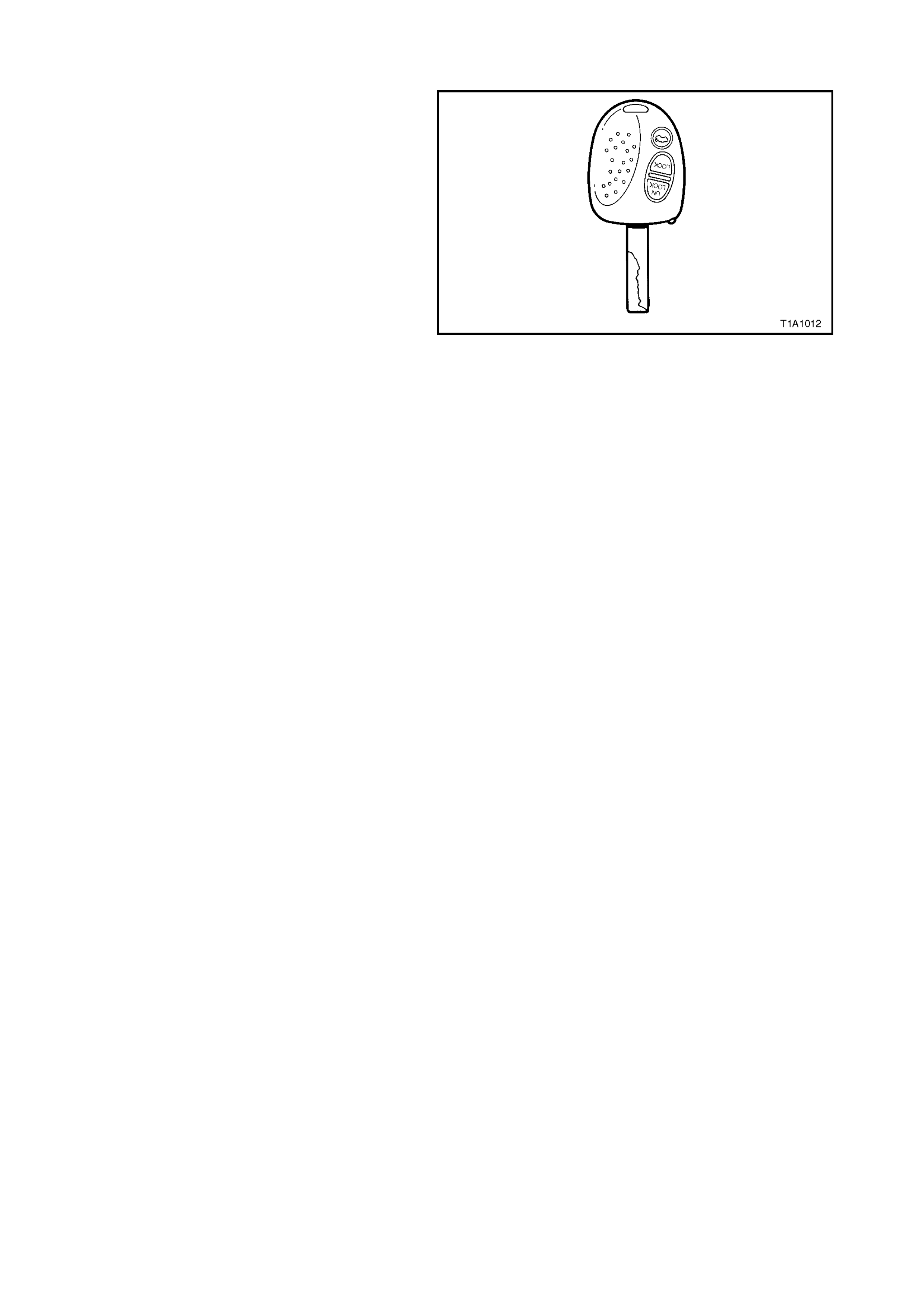
2.5 LOCK CYLINDERS AND KEYS
A single key locking system is used on all WH
Series models. This three button key operates all
locks on the vehicle.
The key identification number is located on the
veh icle security card.
It is essential that this key number be available
should a replacement key be required.
Figure 1A1-1

2.6 METAL REPLACEMENT PARTS REFINISHING
Metal service replacement parts (or assemblies) are painted with a black, ‘high-bake’ factory primer. For
proper adhesion of colour coats in service, the following refinish steps are necessary.
1. Clean part with a wax and grease removing solvent such as Prepsol.
2. Scuff -s and panel lightly with wet or dry number 400 paper and water. Avoid cut-thr oughs. Reclean part,
then apply sealer to entire part.
3. If factory prim er coat has been cut through, apply metal conditioner to the exposed bare m etal. Follow
directions on container label.
4. Apply primer-surfacer to entire part; allow to dry thoroughly before sanding.
5. Sand primer-surfacer using wet or dry number 400 paper and water. Do not sand sealer.
6. Re-clean part.
7. Apply colour coats to parts.
8. Follow direction on container label for drying time before compounding.
9. Compound part by hand or with power equipment.
10. Non-sealing polish may be applied after rub-out if desired. Waxes however, should NOT be applied
until the paint finish has aged for at least two months.

2.7 BODY LUBRICATION
The moving mechanical parts of the body which have metal to metal contact are lubricated at assembly.
Operating conditions, whether normal or otherwise, determine the effective life of the lubricant and for this
reason, lubrication in service is important. Equally important is the type of lubricant to be used and, for your
guidance, we list locations and recommended lubricants.
WARNING: CARELESS OR EXCESSI VE APPLICATION OF BODY LUBRICANTS CAN RESULT IN
STAINING OF PA INT FINISH, INTERIOR TRIM OR DAMAGE TO CLOTHING. USE LUBRICANTS
SPARINGLY AND REMOVE ACCIDENTAL APPLICATION FROM PAINT FINISH IMMEDIATELY.
PARTS READILY ACCES SIBLE
Where practical, use lithium grease; otherwise use light oil.
Engine Hood Catch
Engine Hood Lock
Engine Hood Hinge
Door Hinge Sleeves and Check Links
Rear Compartment Lid Hinge
Rear Compartment Lid Lock Mechanism
Lock Cylinders
Apply Powdered Graphite through Key aperture
(do not oil).
Ignition Lock Cylinder
Door Lock Cylinder
Instrument Panel Compartment Lock Cylinder
Door Lock Striker Bolt/Fork Bolt
Use Solidoil or equivalent.
Door Lock Striker Bolt
Door Lock Fork Bolt
PARTS CONCEALED NECESSITATING DISASSEMBLY
Where practicable, use lithium grease, otherwise use light oil.
Door Window Regulator
Door Window Cams
Door Lock Mechanism
Door Lock Remote Control
Front Seat Adjuster
Driver’s Seat Height Adjuster
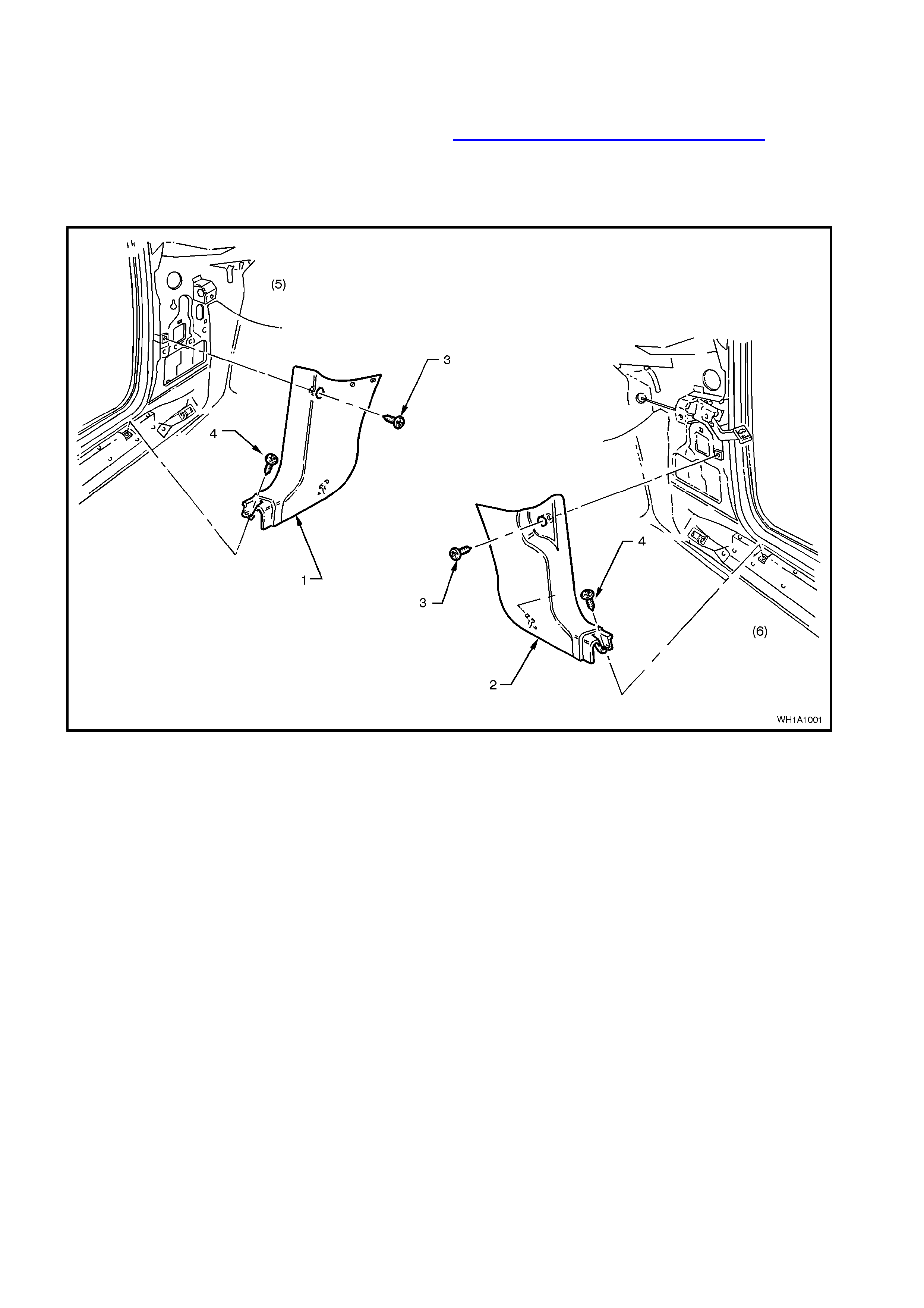
2.8 SHROUD LOWER TRIM ASSEMBLY
REMOVE
1. Remove the dash panel lower trim assembly (refer Section 1A3 Instrument Panel and Consol) and
release the forward section of rocker panel cover.
2. Remove the upper retainer screw (3) and the screw (4) beneath the rocker panel cover securing the
shroud lower trim assembly (2) to the rocker panel.
3. Pull the shroud lower trim assembly rearward from the retainer, removing the assembly.
Figure 1A1-2
Legend
1. Shroud lower trim assembly LHS.
2. Shroud lower trim assembly RHS.
3. Shroud upper retainer screw.
4. Shroud to Rocker Panel screw.
5. LHS.
6. RHS.
REINSTALL
Reverse removal operations.
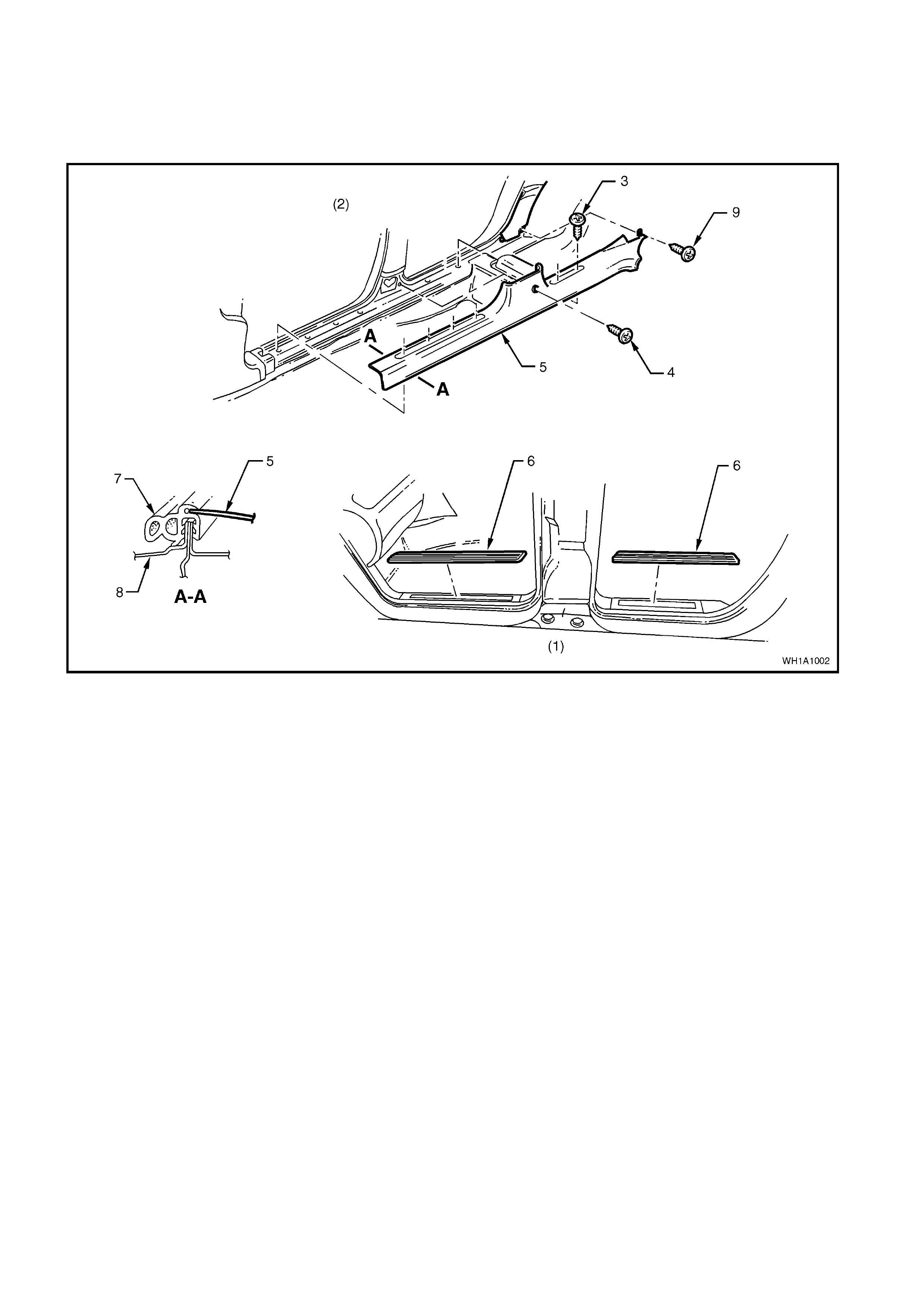
2.9 INNER ROCKER PANEL COVER
REMOVE
Remove rocker panel cover inserts (6) and rocker panel cover retainer screws (3,4 and 9) from rocker
panel removing cover assembly.
Figure 1A1-3
Legend
1. Left Hand Side.
2. Right Hand Side.
3. Screw (6 Places).
4. Screw.
5. Inner Rocker Panel Cover.
6. Cover Insert.
7. Door Seal.
8. Door Frame Opening.
9. Screw.
REINSTALL
Reverse removal operations.
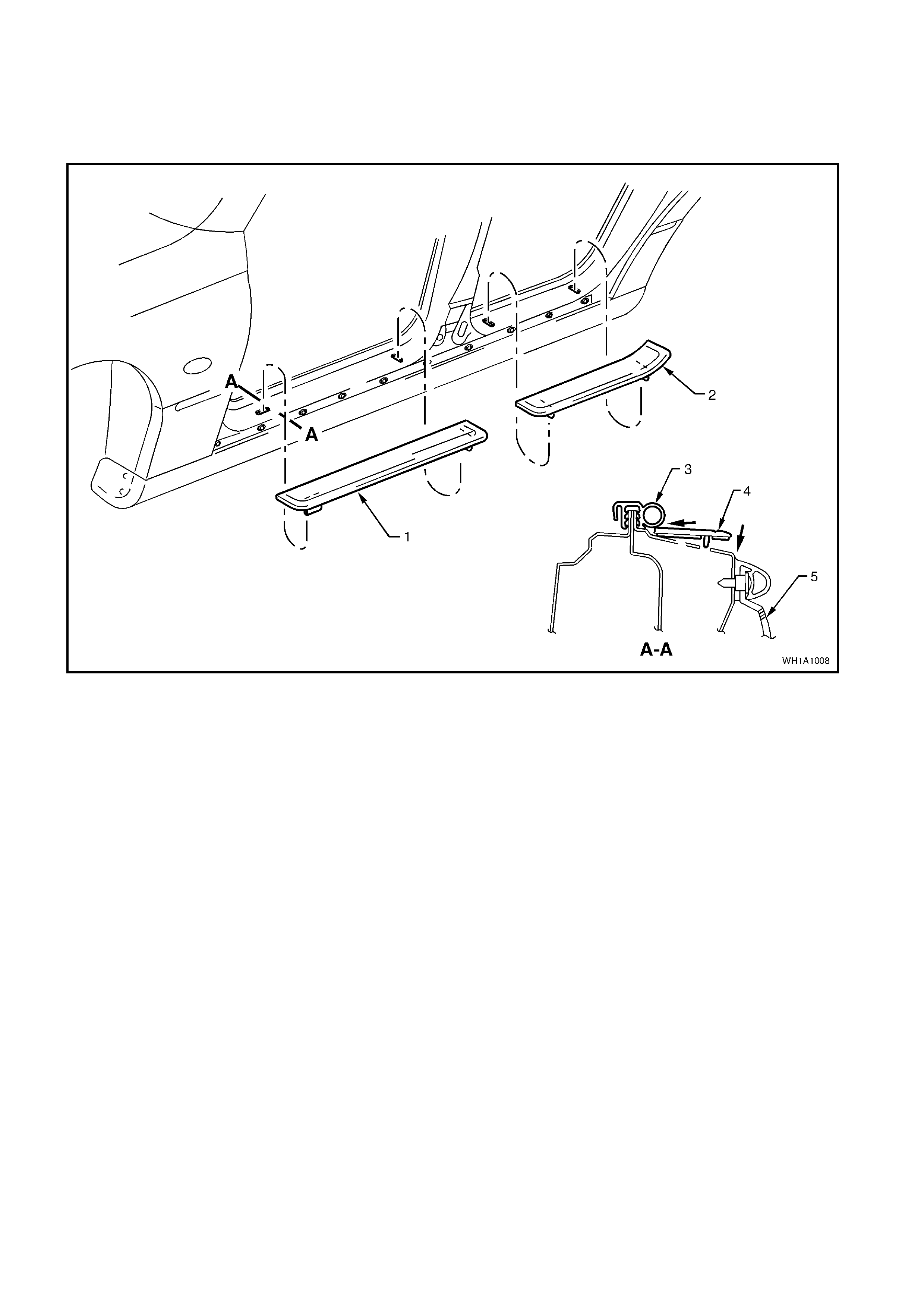
2.10 ROCKER PANEL OUTER COVER
REMOVE
Using a wide bladed tool, carefully prise rocker panel outer cover from rocker panel and remove cover
assembly.
Figure 1A1-4
Legend
1. Front rocker panel outer cover.
2. Rear rocker panel outer cover.
3. Door seal.
4. Rocker panel outer cover.
5. Rocker panel skirt.
REINSTALL
Reverse removal operations.

2.11 FLOOR COVERING ASSEMBLY - BODY
REMOVE
1. Disconnect battery ground cable.
2. Remove rocker panel cover, refer to 2.9
INNER ROCKER PANEL COVER in this
Section.
3. Remove transmission console, refer to
Section 1A3 INSTRUMENT PANEL AND
CONSOLE.
4. Remove the two f ootrest pad retainer screws
removing the footrest.
5. Remove the front seat assemblies and rear
seat cushion assembly, refer to Section 1A7
SEAT & SEAT BELT ASSEMBLIES.
6. Lift covers and remove bolts securing seat
belt buck le ass emblies to tr ans miss ion tunnel
and the outer f ront s eat belt lower attachment
bolts refer to Section 1A7 SEAT & SEAT
BELT ASSEMBLIES.
7. Unplug the air conditioning drain tube from
the floor pan, ease floor covering from
around instrument panel carrier rail and
remove floor covering.
REINSTALL
Reverse removal operations.
FRONT SEAT BELT ATTACHING
BOLTS AND SEAT BELT BUCKLE
ASSEMBLY ATTACHING BOLTS
TORQUE SPECIFICATION
35 - 50 Nm
FRONT SEAT ATTACHING BOLT
TORQUE SPECIFICATION 35 - 50 Nm
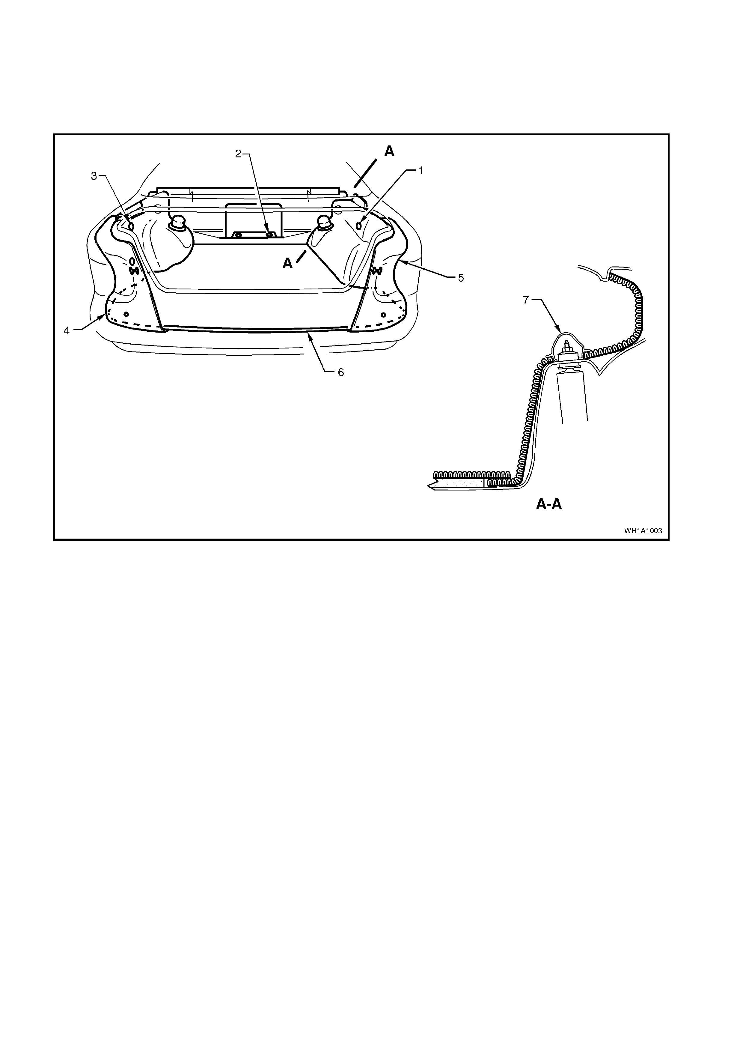
2.12 FLOOR COVERING ASSEMBLY- REAR COMPARTMENT
Removal and installation of the rear compartment carpet involves removal of the spare wheel cover and
carpet assembly. During reinstallation locate the carpet edges and install the spare wheel cover.
The wheelhouse trim is held in place by retainers and at the rear compartment lid opening by the rear
crossmember trim.
Figure 1A1-5
Legend
1. Retainer.
2. Retainer.
3. Retainer.
4. Rear compartment wheelhouse carpet L.H.S.
5. Rear compartment wheelhouse carpet R.H.S.
6. Spare wheel carpet assembly .
7. Shock absorber end cap.
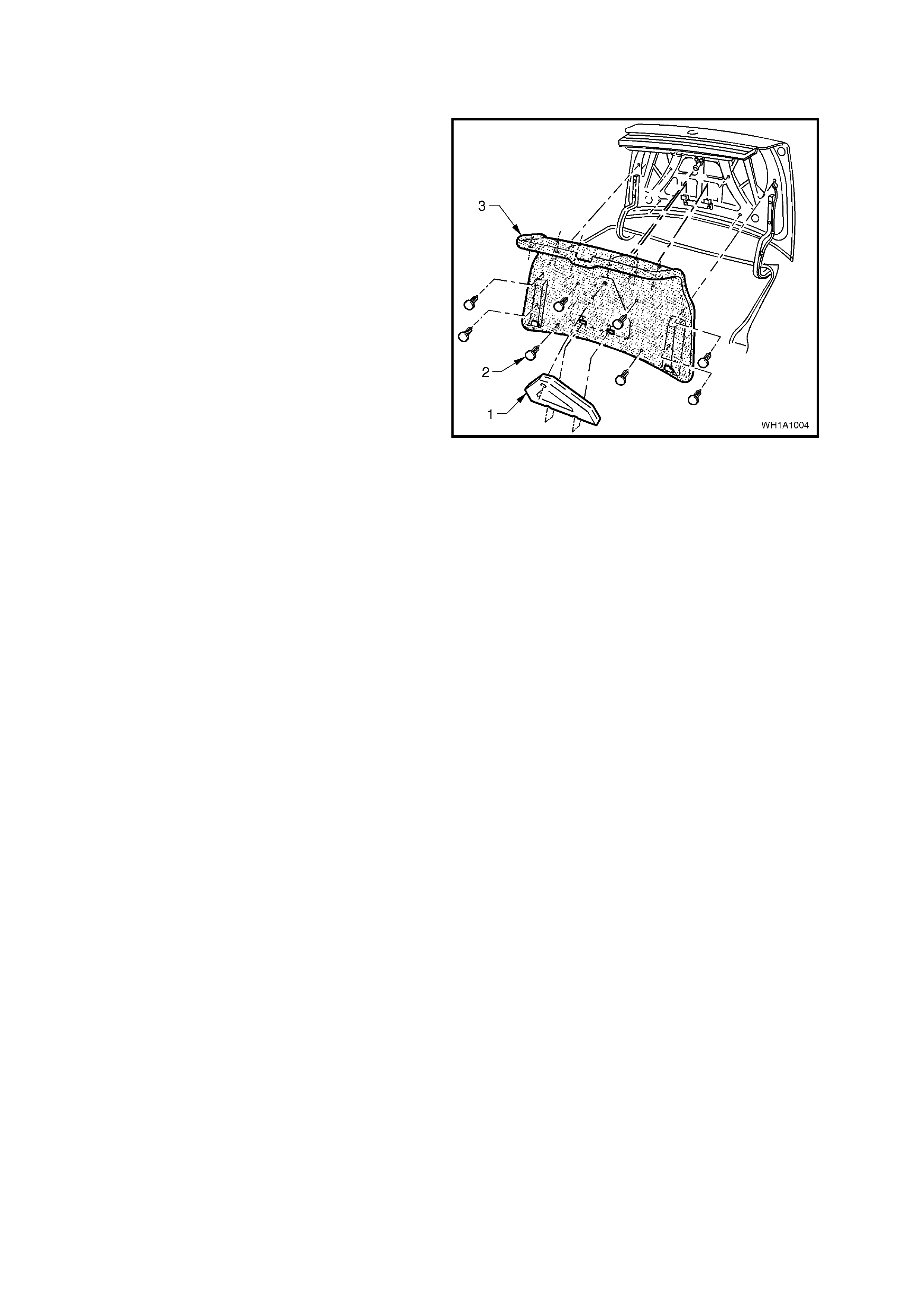
2.13 CARPET ASSEMBLY - REAR COMPARTMENT LID LINER
REMOVE
1. Remove the safety triangle (1) from its position
in the rear compartment lid.
2. Remove the sixteen retainers (2) securing the
carpet assembly (3) to the rear compartment
lid.
3. Move the carpet assembly from its position on
the rear compartment lid, open the hinge slots
at the base of the c arpet ass em bly and rem ove
the carpet.
Figure 1A-6
REINSTALL
Reverse removal operations.

2.14 BODY STRUCTURE PANELS
UNDERBODY
1. Reinforcing assembly - inner seat attachment.
2. Reinforcing - floor panel side.
3. Floor assembly - front.
4. Mount assembly - power unit.
5. Extension assembly - floor panel front.
6. Brace - longitudinal to front floor.
7. Bracket - ABS modulator upper.
8. Bracket - ABS modulator lower.
9. Bracket - support modulator lower.
10. Tray assembly - battery.
11. Bracket assembly - -theft deterrent horn
mounting.
12. Panel assembly - front fender skirt.
13. Frame work - underbody front.
14. Cross member assembly - front (member
assembly - front lower).
15. Panel assembly – front.
16. Panel assembly - front upper.
17. Front panel - side.
18. Bracket - radiator support side.
19. Support - front panel side.
20. Bracket - bumper beam mounting
21. Console - front panel.
22. Longitudinal assembly (front).
23. Crossmember assembly (RH) centre.
24. Crossmember assembly (LH) centre.
25. Hook tie down rear.
26. Extension assembly - longitudinal (rear).
27. Crossmember assembly - rear.
28. Bracket assembly - brake hose.
29. Longitudinal - complete.
30. Frame work assembly - rear.
31. Reinforcement assembly - back panel lower.
32. Bumper beam mounting bracket assembly
(rear).
33. Heat shield assembly - intermediate muffler
LH.
34. Heat shield assembly - intermediate muffler
RH.
35. Heat shield - rear muffler.
36. Web plate – rear Left Hand.
37. Stand assembly - spare wheel.
38. Back panel assembly - lower.
39. Web plate – rear Right Hand.
40. Floor assembly - rear.
41. Reinforcement assembly - centre bearing.
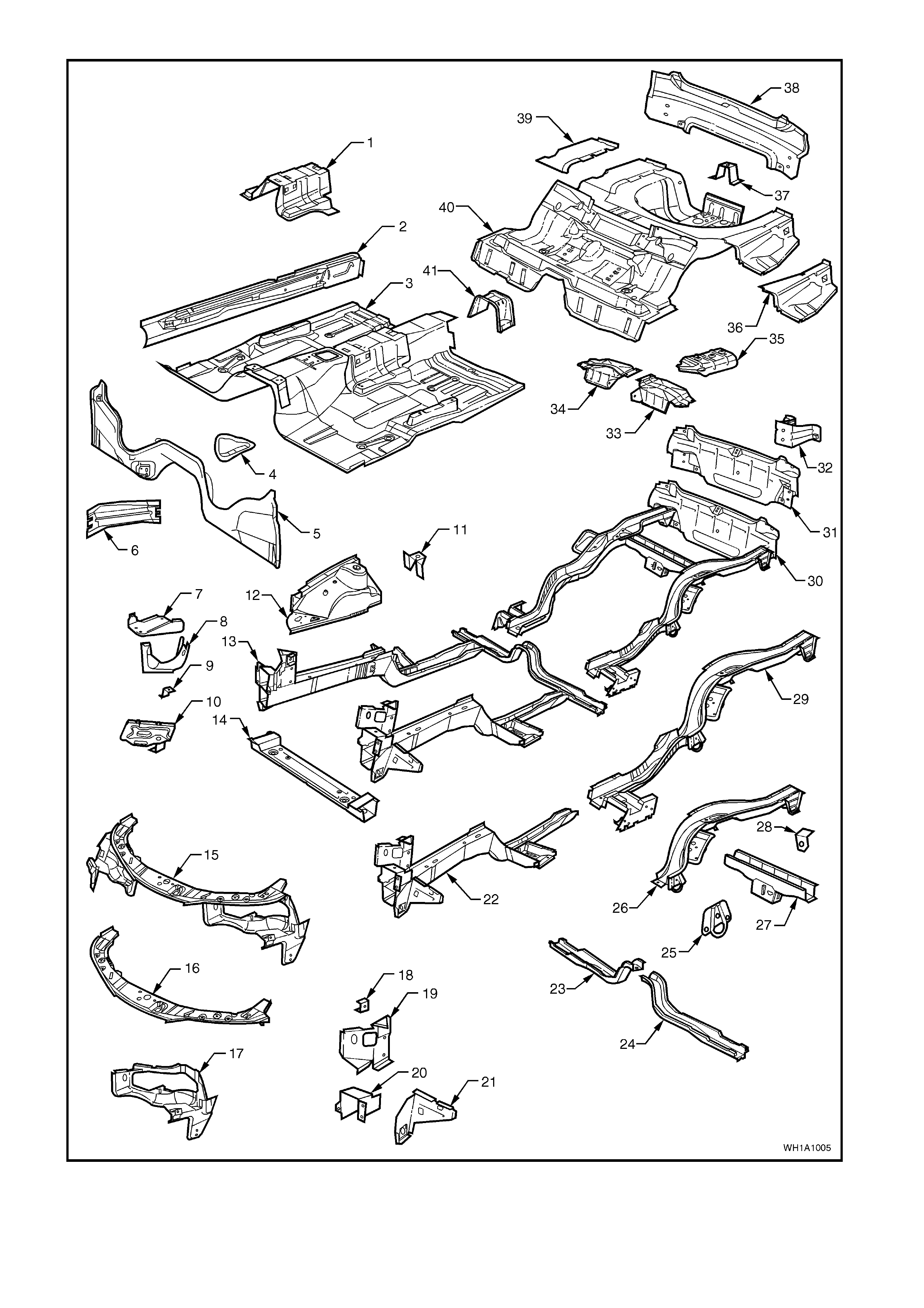
Figure 1A1-7

BODY SIDE
1. Bracket - trim attachment.
2. Pillar - front body inner.
3. Brace - wheelhouse (front).
4. Fender panel (front).
5. Front fender liner.
6. Support - fender.
7. Angle - fender lower.
8. Frame assembly - door opening.
9. Angle - fender upper.
10. Support - front door check.
11. Support - rear door check.
12. Panel - rear quarter (side panel outer).
13. Liner - rear wheelhouse.
14. Gusset - side panel.
15. Insert assembly - tail lamp.
16. Cap - fuel filler.
17. Side panel assembly - inner.
18. Frame - side front roof.
19. Wheelhouse inner assembly.
20. Reinforcement - ‘A’ pillar upper.
21. Brace - upper wheelhouse.
22. Panel assembly - back upper.
23. Frame - roof rear.
24. Support - roof.
25. Panel - roof.
26. Support - roof.
27. Rail - windshield header.
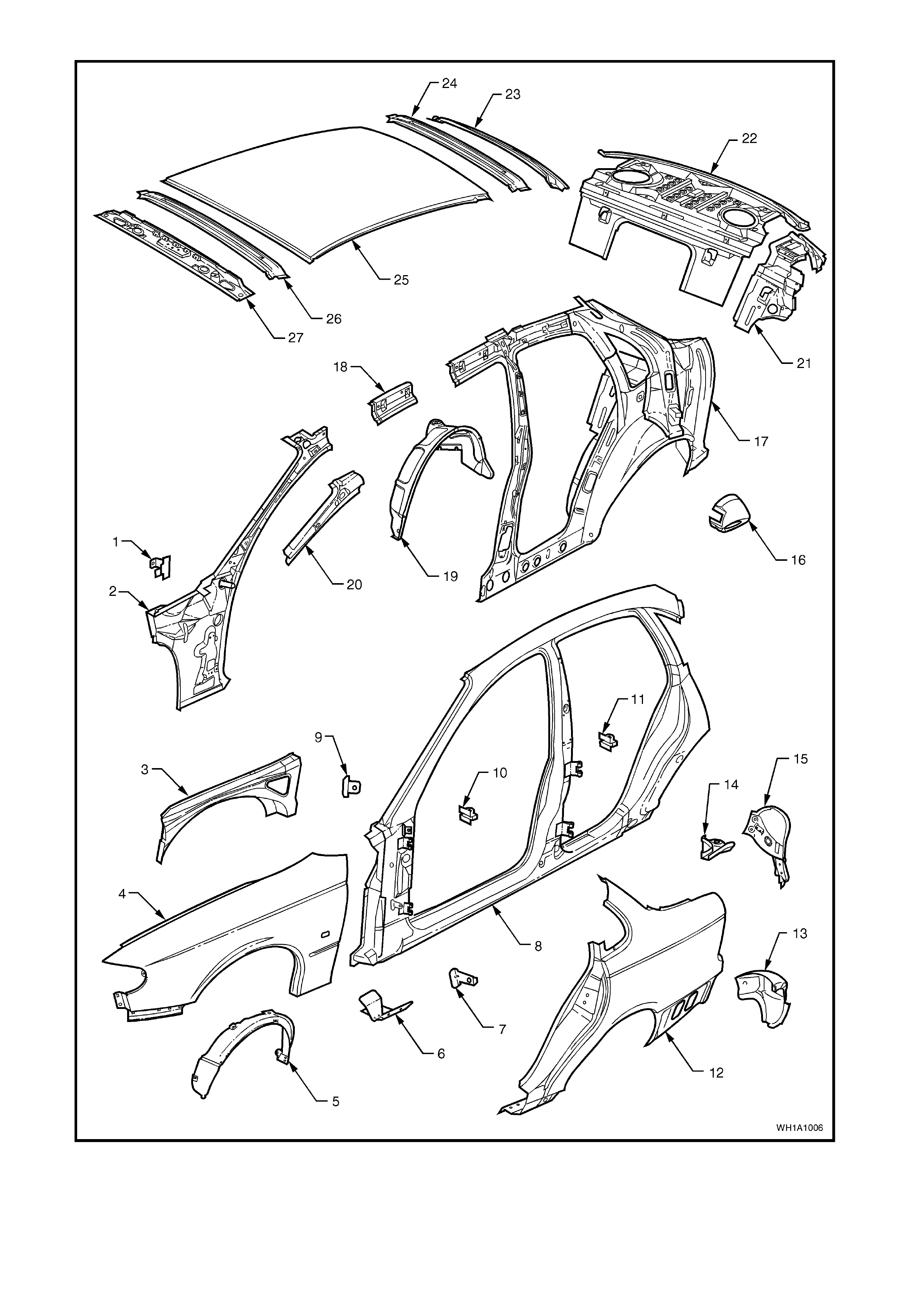
Figure 1A1-8

BODY SHELL
1. Body shell.
2. Engine hood.
3. Hinge assembly - engine hood.
4. Door assembly - front (inner).
5. Panel assembly - front door outer.
6. Panel assembly - rear door outer.
7. Door assembly - rear (inner).
8. Arm and bracket assembly - decklid hinge.
9. Decklid assembly - rear.
10. Dash panel assembly.
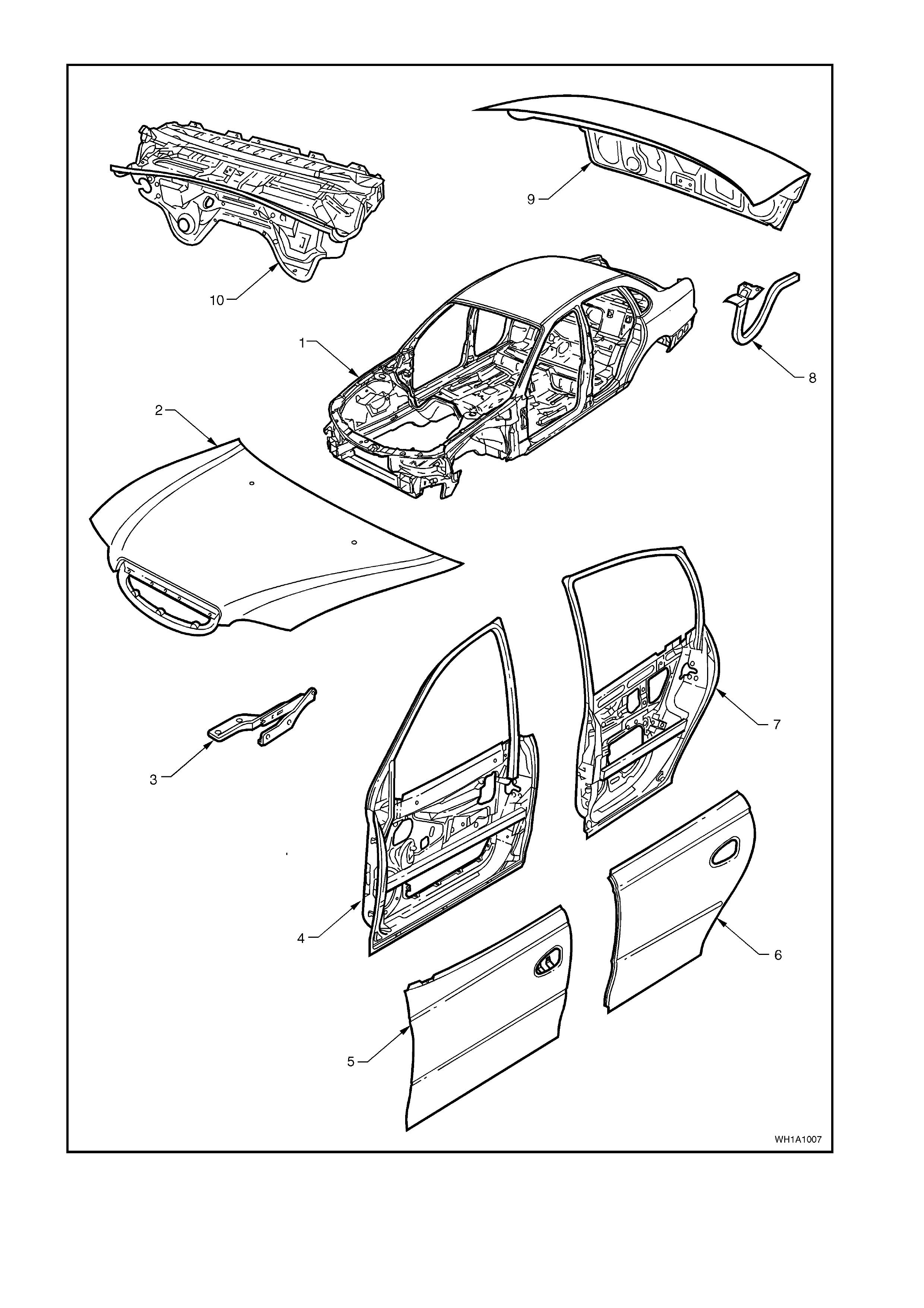
Figure 1A1-9

3. TORQUE WRENCH SPECIFICATIONS
Nm
Shroud lower trim assembly securing screws....................... 0.7 - 1
Rocker panel cover retaining screws.................................... 1 - 3
Front seat belt attaching bolts............................................... 35 - 50
Seat belt buckle assembly attaching bolts............................ 35 - 50
Foot rest pad securing screws.............................................. 2 - 5