
SECTION 1A2 - BODY DIMENSIONS
IMPORTANT
Before performing any Service Operation or other procedure described in this Section, refer to
Section 00 CAUTIONS AND NOTES for correct workshop practices with regard to safety and/or
property damage.
1. GENERAL DESCRI PTI O N
The WH Series is a new vehicle des ign with sheetm etal, interior trim , and air c onditioning system c hanges.
Front bumper fascias accommodate engine cooling entry. Head, turn signal and rear lamps complement
the design changes.

2. SERVICE OPERATIONS
2.1 BODY DIMENS IONS
Correct underbody alignment is essential, as any misalignment of the underbody can adversely affect
suspension, fitment of doors, engine hood or rear compartment lid. The underbody should therefore be
aligned to within ±1.5 mm of dimensions specified in Figures 1A2-1, 1A2-2, 1A2-3, 1A2-4, and 1A2-5.
These dimensions should be accurately checked with a tram gauge consisting of a parallel bar or rod, fitted
with two adjustable trammels, capable of gauging all underbody dimensions specified.
In preparing for an underbody alignment check, place the vehicle on a level surface with the weight of the
body supported at wheel locations.
Dimensions to holes are to be taken from the centreline.
Body dimensions are to be taken to the outside surface of the sheetmetal.
All dimensions are to be measured as shown.
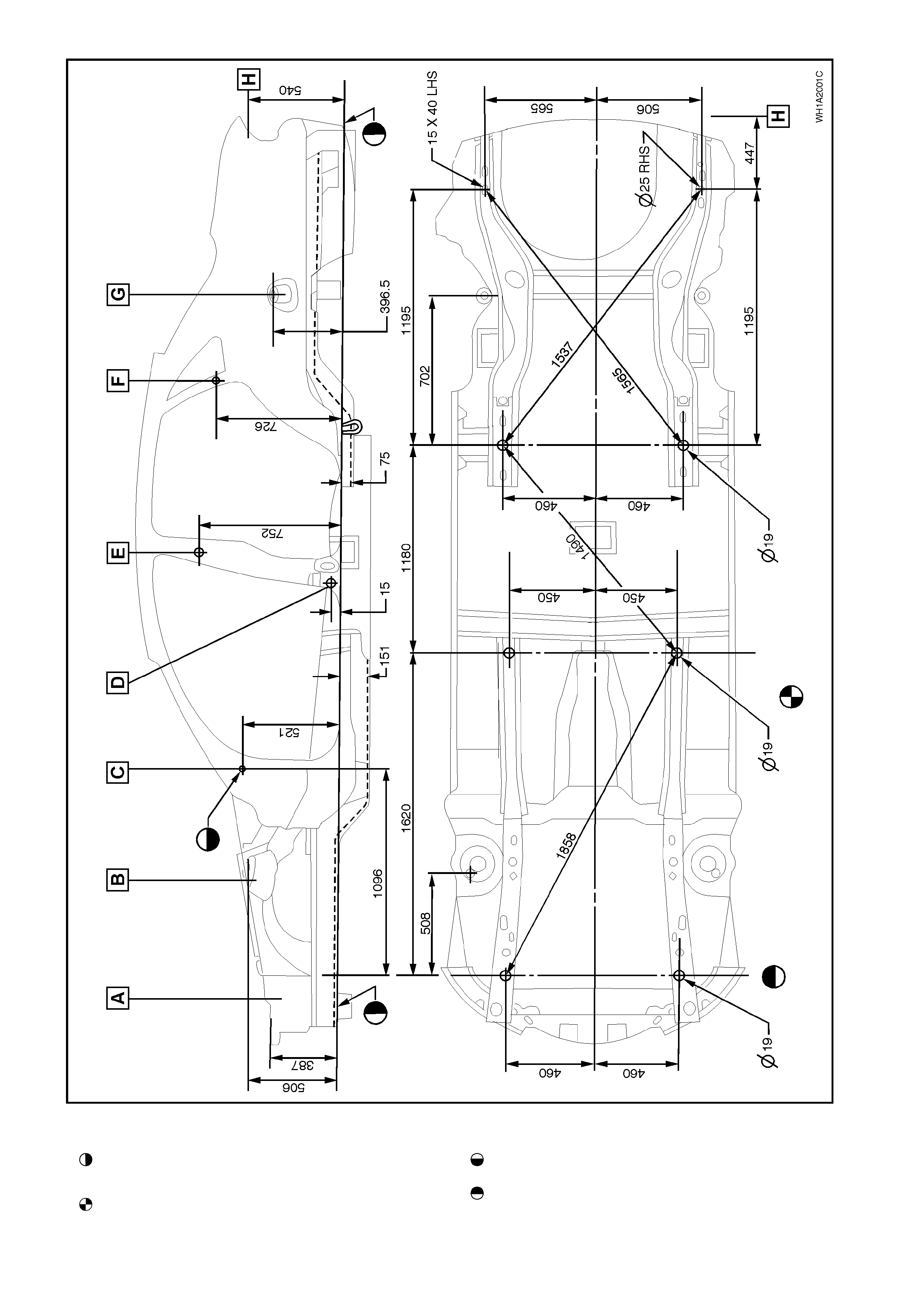
Figure 1A2-1
Legend
Datum surface under side of longitudinal R &
LH.
All dimensions in mm. measured from centre
of holes on outside of metal.
Cockpit module attachment.
Datum surface under side of longitudinal R &
LH.
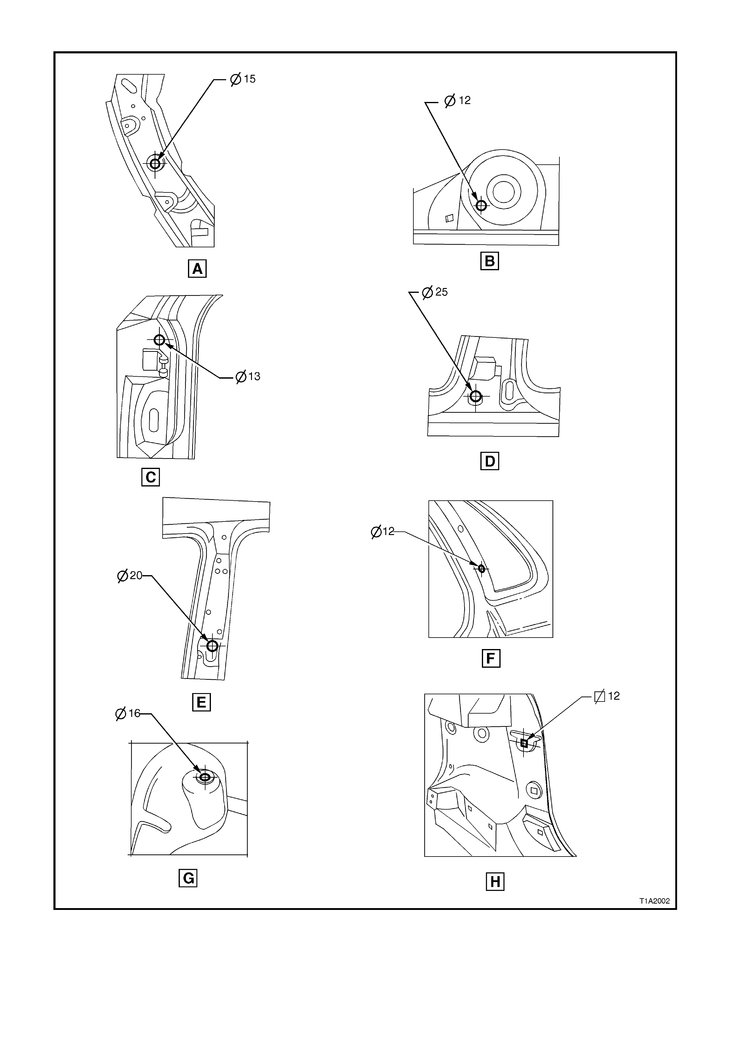
Figure 1A2-2
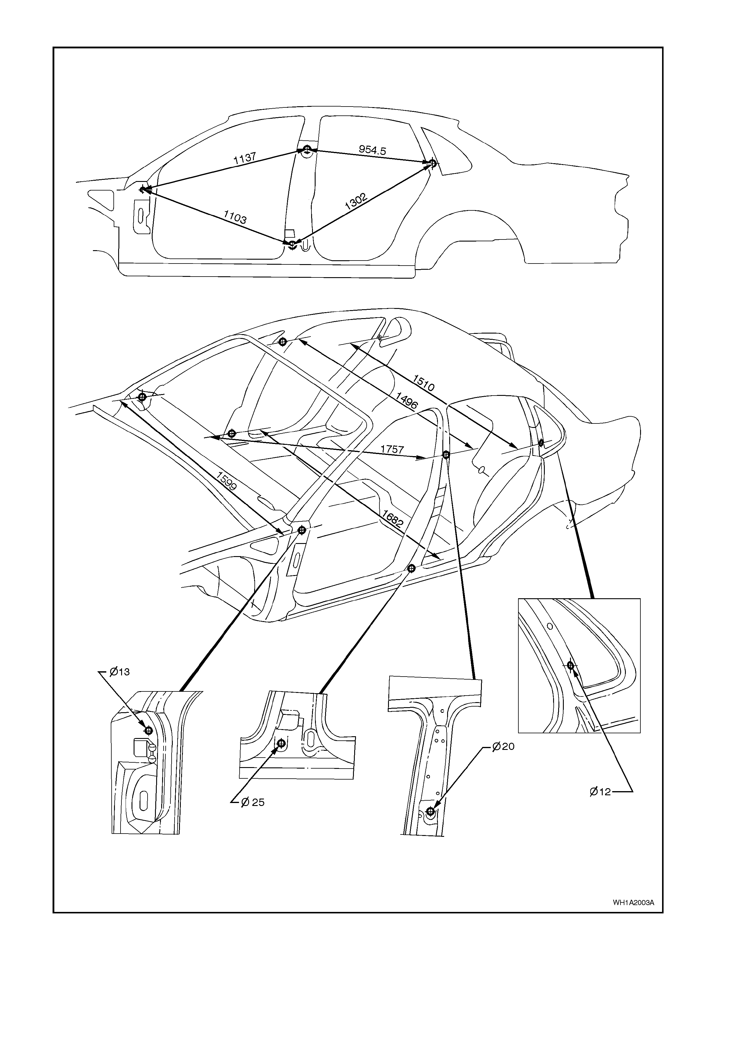
Figure 1A2-3
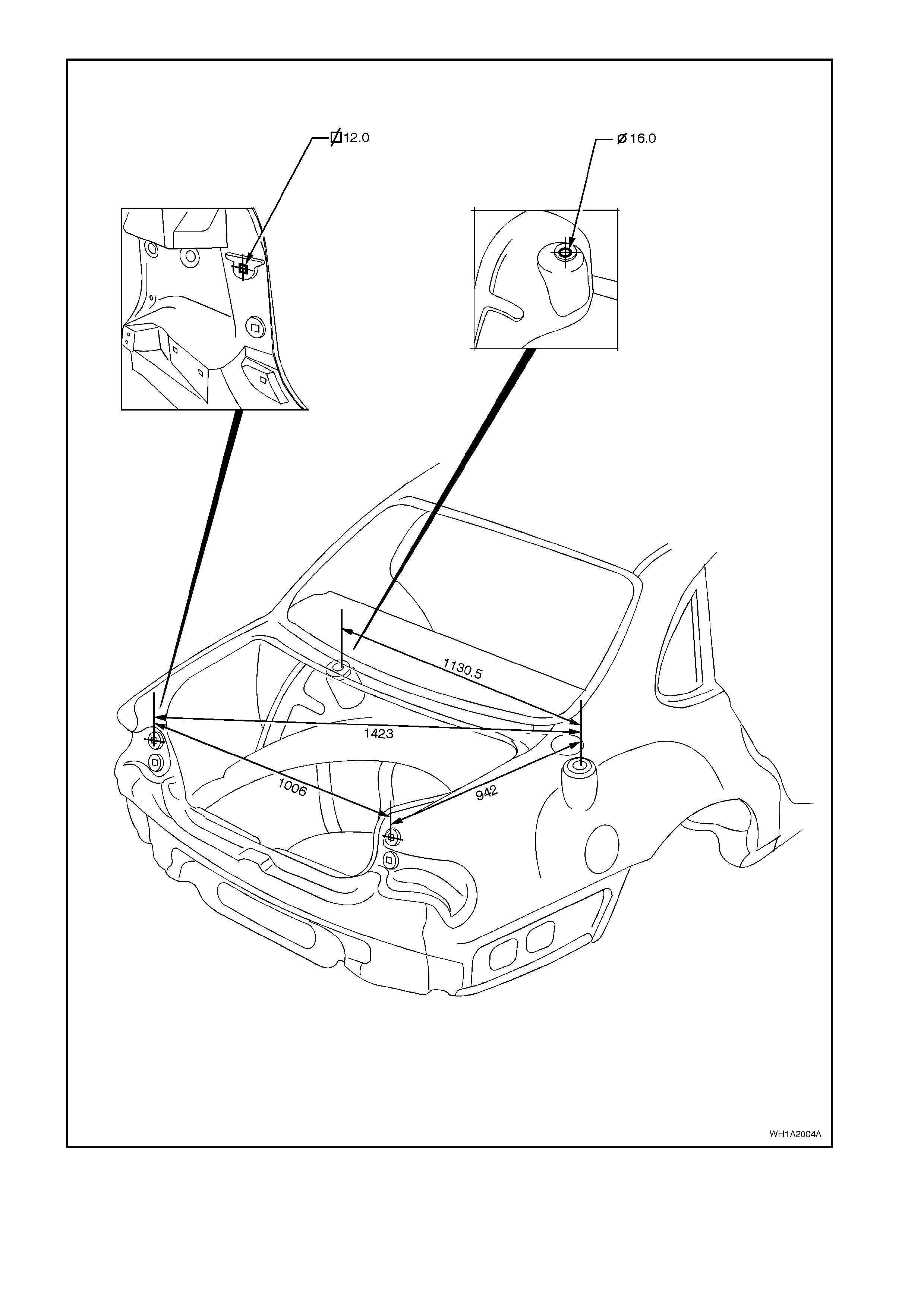
Figure 1A2-4
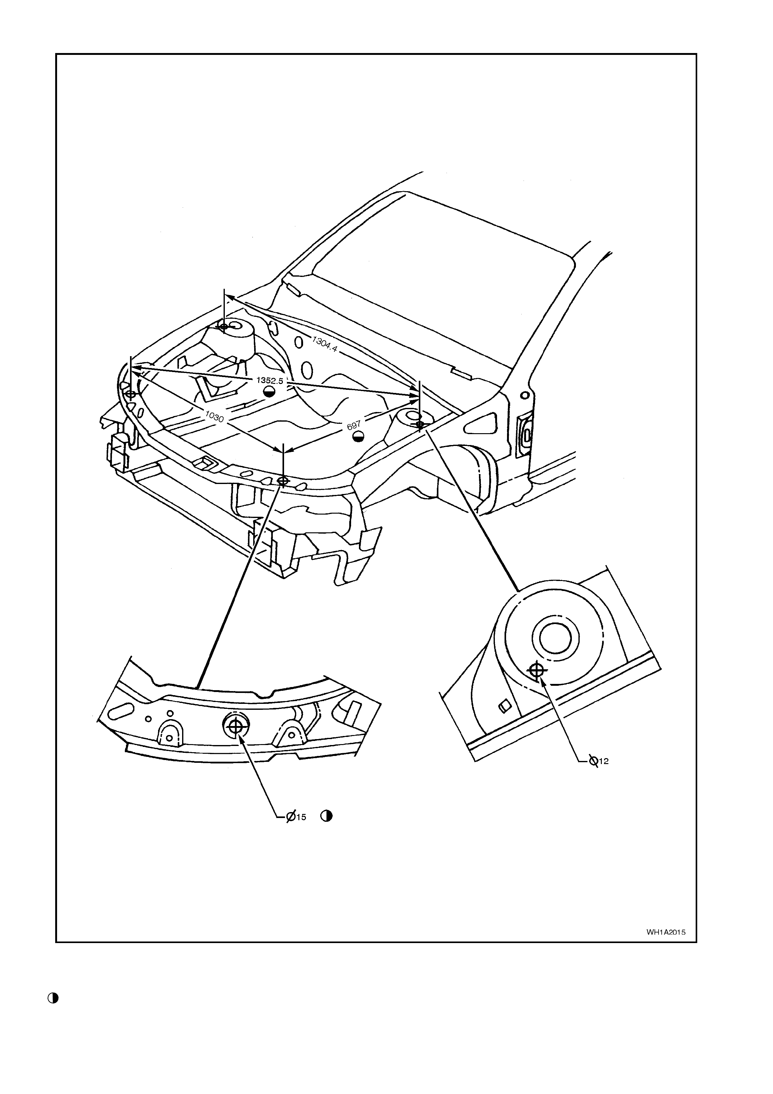
Figure 1A2-5
Legend
All dimensions in mm. measured from centre of
holes on outside of metal.
2.2 FRONT SUSPENSION CROSSMEMBER ALIGNMENT
NOTE: Ensure that body dimensions are within specified limits prior to commencing any crossmember
alignment. Refer to 2.1 BODY DIMENSIONS in this Section.
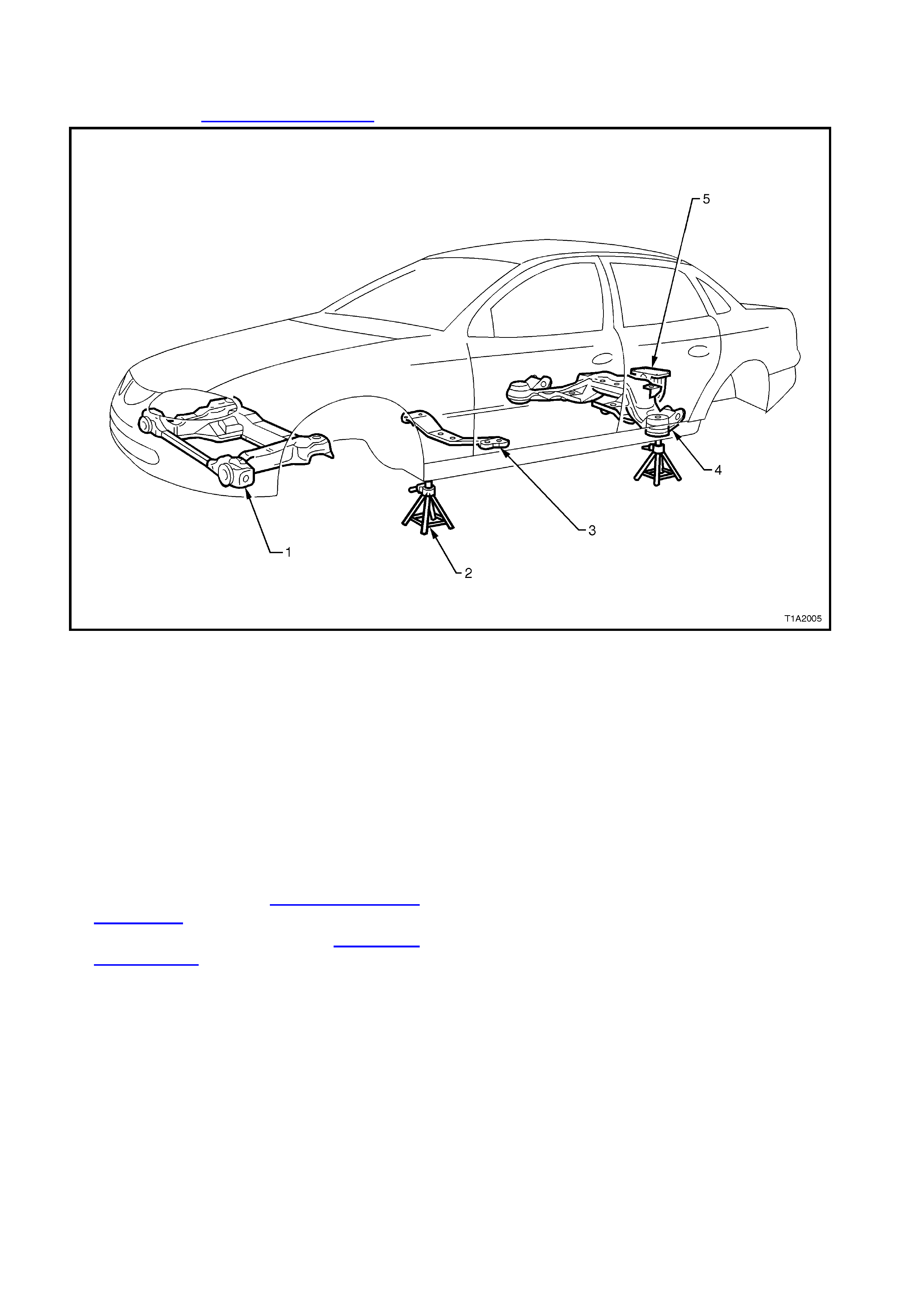
Figure 1A2-6
Legend
1. Front suspension crossmember.
2. Chassis stands.
3. Transmission crossmember.
4. Rear suspension crossmember.
5. Final drive rear mount.
NOTE: Front suspension crossmember centring
tool needs to be held in position during the
alignment procedure. Therefore, assistance will be
required to complete this operation.
1. Using chassis stands support vehicle at hoist
pad locations.
2. Remove wheels, refer to Section 10 WHEELS
AND TYRES.
3. Remove engine hood, refer to Section 1B
SHEETMETAL.
4. Support engine with overhead lifting device and
raise slightly to take weight off engine mounts.
5. From underneath vehicle loosen front
crossmember attaching bolts.
6. Remove left hand rear attaching bolt and
replace with the locating pin with front
suspension crossmember centering tool No.
AU 457.
7. Fit front suspension c rossm ember centring tool
No. AU 457.
NOTE: Front suspension crossmember centring
tool locates into ∅ 19 mm body datum holes
positioned towards front of vehicle.
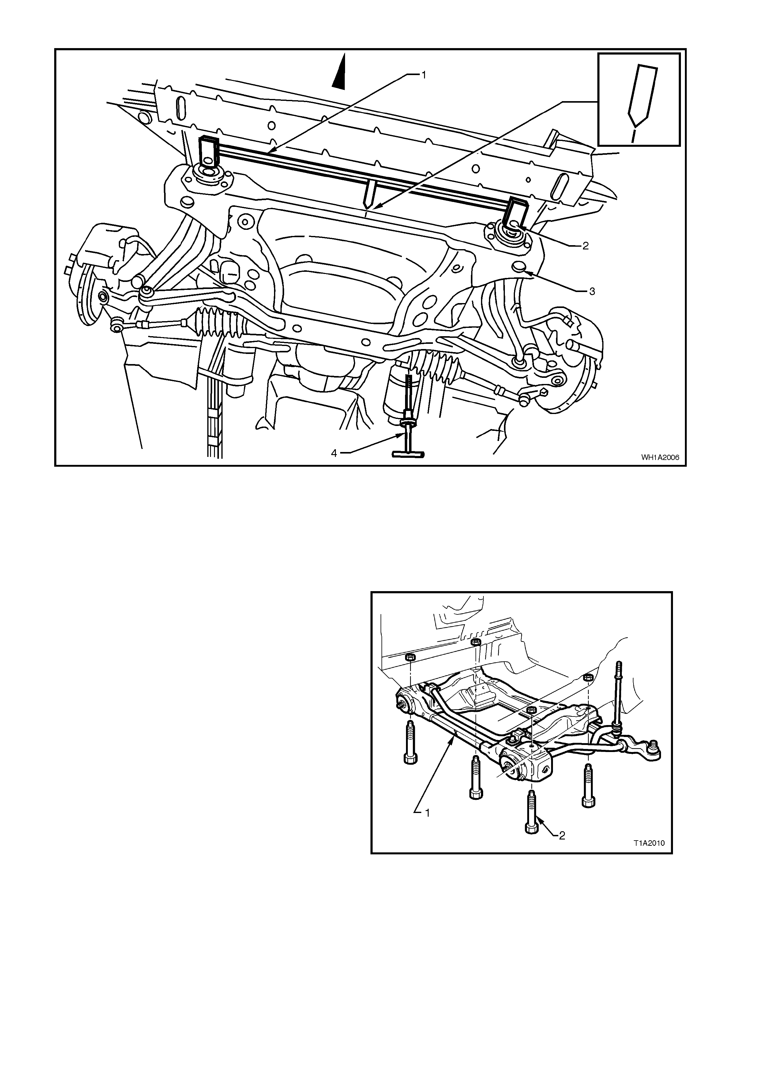
Figure 1A2-7
Legend
1. Front crossmember centering Tool No.
AU457.
2. Datum pin (2 places).
3. Attaching bolt (8 places).
4. Locating pin position.
5. Front crossmember centering tool no. AU 457
8. With the help of an assistant, manoeuvre the
front suspension crossmember so that the
reference mark on the crossmem ber is aligned
with the pointer on the centring tool.
NOTE: Front suspension crossmember has an ‘I’
stamped on the front to aid in aligning to fixture
pointer.
IMPORTANT: Front suspension crossmember
attaching bolts must be renewed after each
loosening and may be replaced one at a time
during this alignment procedure.
Alignment of crossmember must be completed
within 20 minutes from installation of new bolts.
Attaching bolts are supplied with a
microencapsulated locking compound applied to
threads that will start to set immediately after
installation and will reach 20% adhesion after 30
minutes. Figure 1A2-8

9. When crossmember is aligned, tighten the
three crossmember attaching bolts.
10. Remove locating pin.
FRONT CROSSMEMBER ATTA CHING 120 - 125
BOLTS T ORQUE SPE CIFICAT ION Nm
11. Reinstall left rear crossmember attaching bolt
and washer and tighten.
12. Remove crossmember aligning fixture.
13. Gently lower engine and remove lifting device.
14. Attach wheels, refer to Section 10 WHEELS
AND TYRES.
15. Remove vehicle from chassis stands.
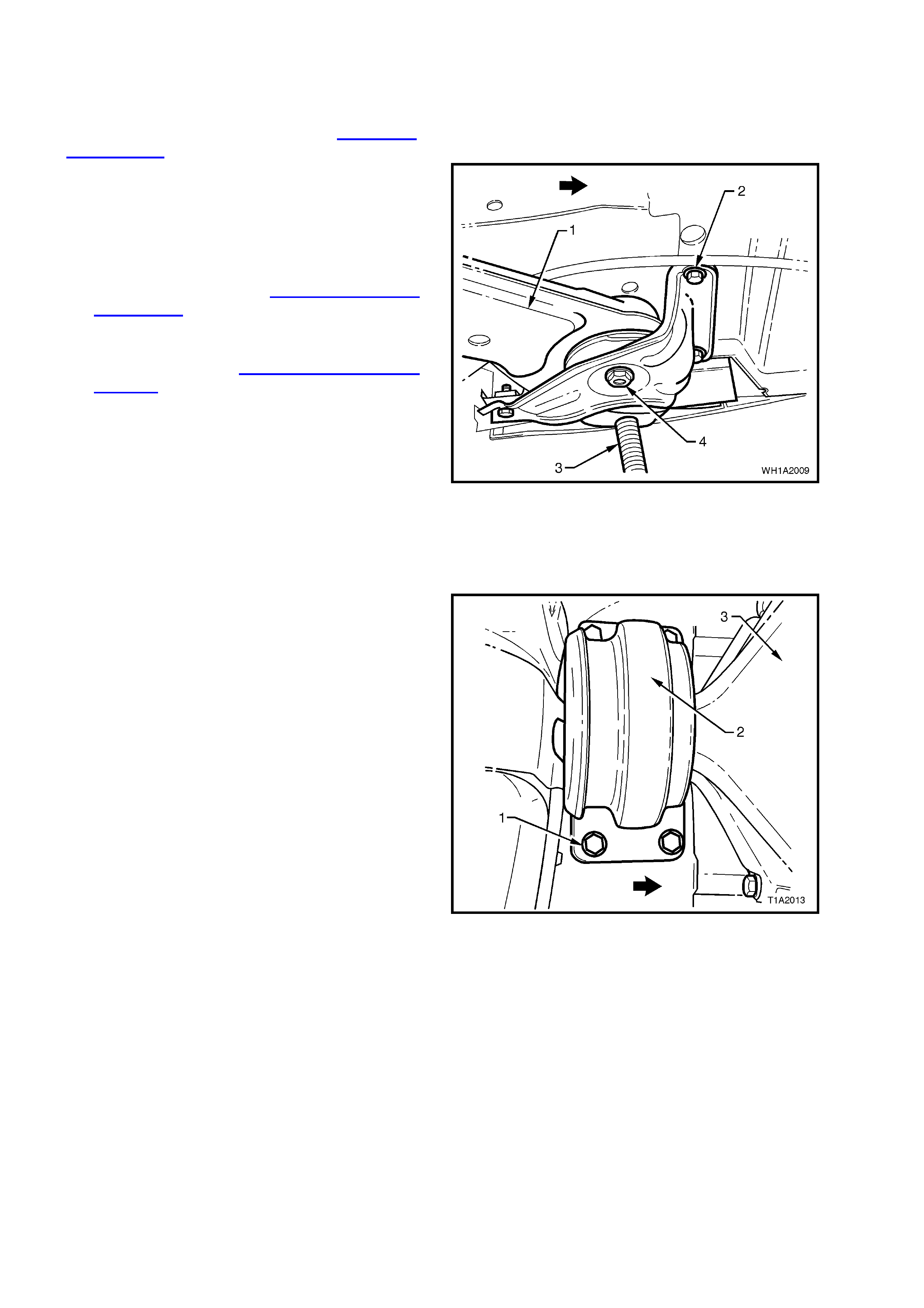
2.3 TRANSMISSION CROSSMEMBER ALIGNMENT
NOTE: Ensure that body dimensions are within
specified limits prior to commencing any
crossmember alignment. Refer to 2.1 BODY
DIMENSIONS in this Section.
1. Using chassis stands support vehicle at hoist
pad locations.
2. From underneath the vehicle, support
transmission with a trolley jack and raise
slightly to take weight off transmission mount
(1).
3. Remove two M8 nuts (2) secur ing transm ission
mount (1) to transmission crossmember (3).
4. Loosen four attaching bolts (4) securing
transmission crossmember to underbody.
5. Centralise transmission crossmember (3)
within bolt holes (4).
6. Tighten the four attaching bolts.
TRANSMISSION CROSSMEMBER
ATTACHING BOLTS TORQUE 50 - 65 Nm
SPECIFICATION
7. With the help of an assistant manoeuvre the
transmission to ensure that the studs
protruding through the crossmember are
centralised within the stud holes.
8. Reinstall M8 nuts (2) securing transmission
mount to transmission crossmember.
TRANSMISSION MOUNT M8 NUTS 20 - 30
TORQUE SPECIFICATION Nm
9. Gently lower trolley jack and remove from
under vehicle.
10. Remove vehicle from chassis stands.
Figure 1A2-9
2.4 REAR SUSPENSION CROSSMEMBER ALIGNMENT
NOTE: 1 Ensure that body dimensions are within
specified limits prior to commencing any
crossmember alignment. Refer to 2.1 BODY
DIMENSIONS in this Section.
NOTE: 2 Rear suspension crossmember centring
tool needs to be held in position during the
alignment pr ocedure. T herefore, as sistance will be
required to complete this operation.
1. Using chassis stands (3) support vehicle at
hoist pad locations.
2. Remove wheels, refer to Section 10 WHEELS
AND TYRES.
3. Remove intermediate muffler and pipe
assembly together with rear muffler and pipe
assembly refer to Section 8B1 EXHAUST
SYSTEM.
4. From underneath the vehicle, support final
drive with a trolley jack and raise s lightly to take
weight off final drive mount.
5. Loosen three M10 screws (2) securing
crossmember to body brace left hand side and
right hand side.
6. Loosen rear suspension crossmember (1)
attaching bolts (M14) (4) left hand side and
right hand side.
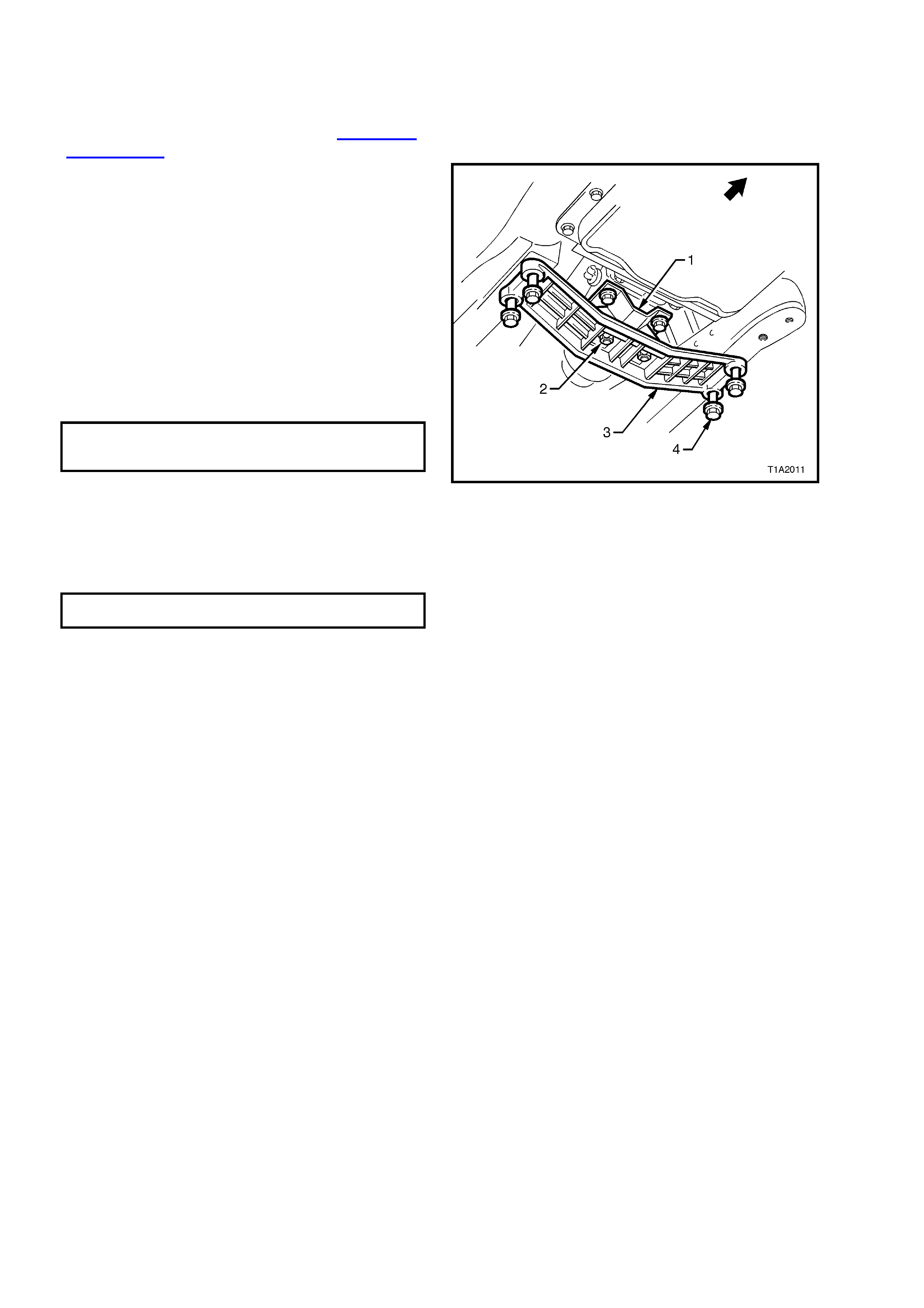
Figure 1A2-10
7. Loosen four bolts (1) securing final drive rear
mount (2) to vehicle underbody.
IMPORTANT: Rear suspension crossmember
attaching bolts and final drive rear m ount attaching
screws must be renewed after each loosening and
may be replaced one at a time during this
alignment procedure.
Alignment of crossmember must be completed
within 20 minutes from installation of new bolts.
Attaching bolts are supplied with a micro
encapsulated locking compound applied to threads
that will start to set immediately after installation
and will reach 20% adhesion after 30 minutes.
Figure 1A2-11
8. Fit rear suspension centring tool No. AU 458.
NOTE: Rear suspension crossmember centring
tool locates into ∅ 19 mm body datum holes
positioned forward of rear suspension
crossmember.
9. With the help of an assistant, manoeuvre the
rear sus pens ion cr os s mem ber until the loc ation
pins of the rear crossmember centring tool
engages the alignment holes on the rear
suspension crossmember.
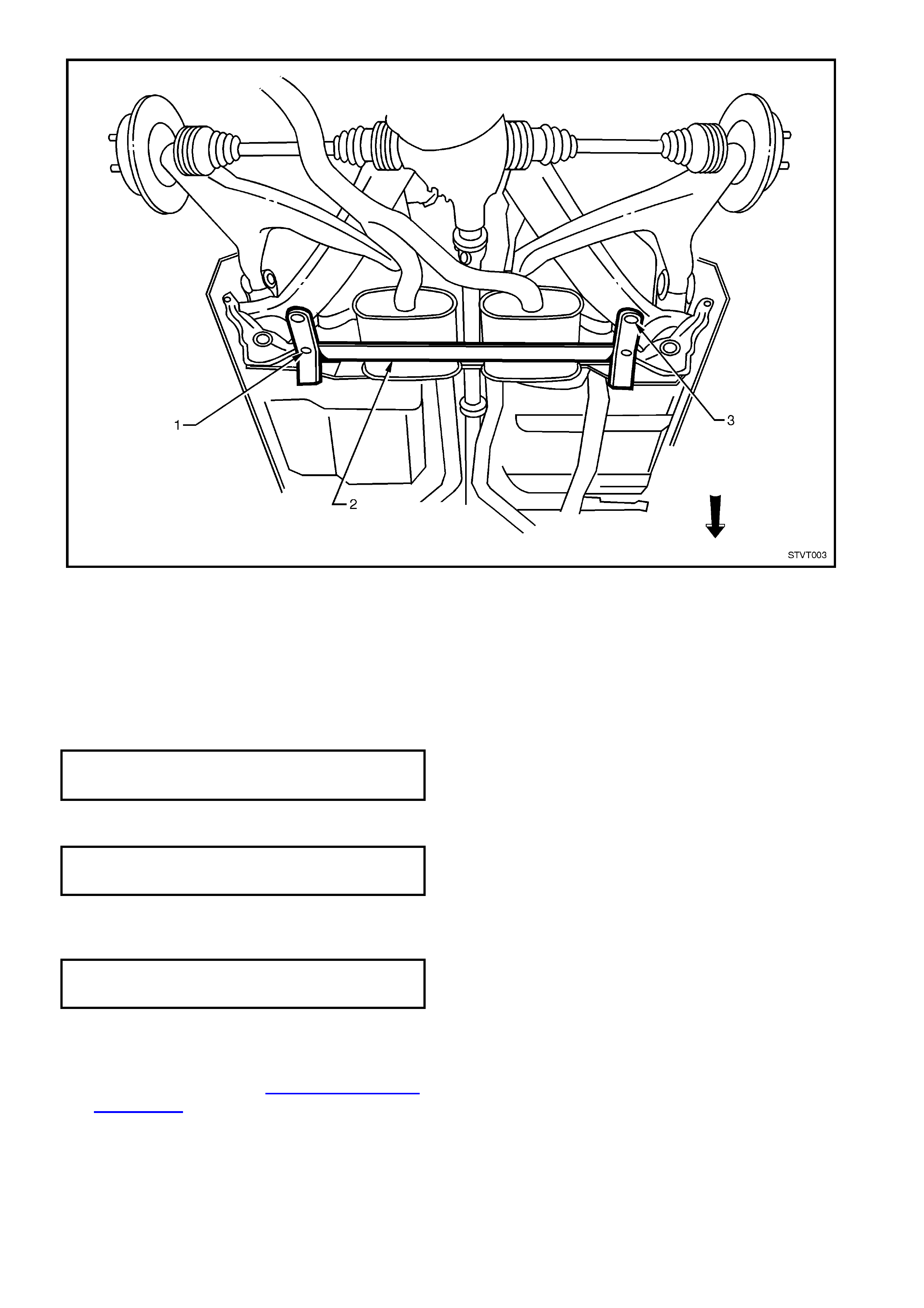
Figure 1A2-12
Legend
1. Datum pin (2 places).
2. Rear crossmember centering Tool No.
AU 458.
3. Locating pins (2 places).
10. Tighten rear suspension crossmember
attaching bolts (M14) left hand side and right
hand side.
REAR SUS P ENSION 125 Nm, rota t e
CROSSMEMBER ATTACHING 30° - 45° with a
BOLTS TORQUE S PECIFI CA T ION mi n. of 135 Nm
11. Tighten four screws securing final drive rear
mount.
FINAL DRIVE RE AR MOUNT
ATTACHING SCREWS 30 - 45 Nm
TORQUE SPECIFICATIONS
12. Tighten three M10 screws securing
crossmember to body brace lefthand side and
righthand side.
CROSSMEMBE R M10 SECURING
SCREWS TORQUE 60 - 85 Nm
SPECIFICATION
13. Remove rear crossmember centring tool.
14. Gently lower trolley jack and remove from
under vehicle.
15. Attach wheels, refer to Section 10 WHEELS
AND TYRES.
16. Remove vehicle from chassis stands.

3. TORQUE WRENCH SPECIFI CATIONS Nm
Front crossmember attaching bolts ...................................... 120 - 125
Transmission crossmember attaching bolts......................... 50 - 65
Transmission mount securing nuts....................................... 20 - 30
Rear suspension crossmember attaching bolts (M14) ......... 125 Nm and rotate
30° - 45° with a
min. of 135 Nm
Final drive rear mount attaching screws............................... 30 - 45
Crossmember securing screws (M10).................................. 60 - 85
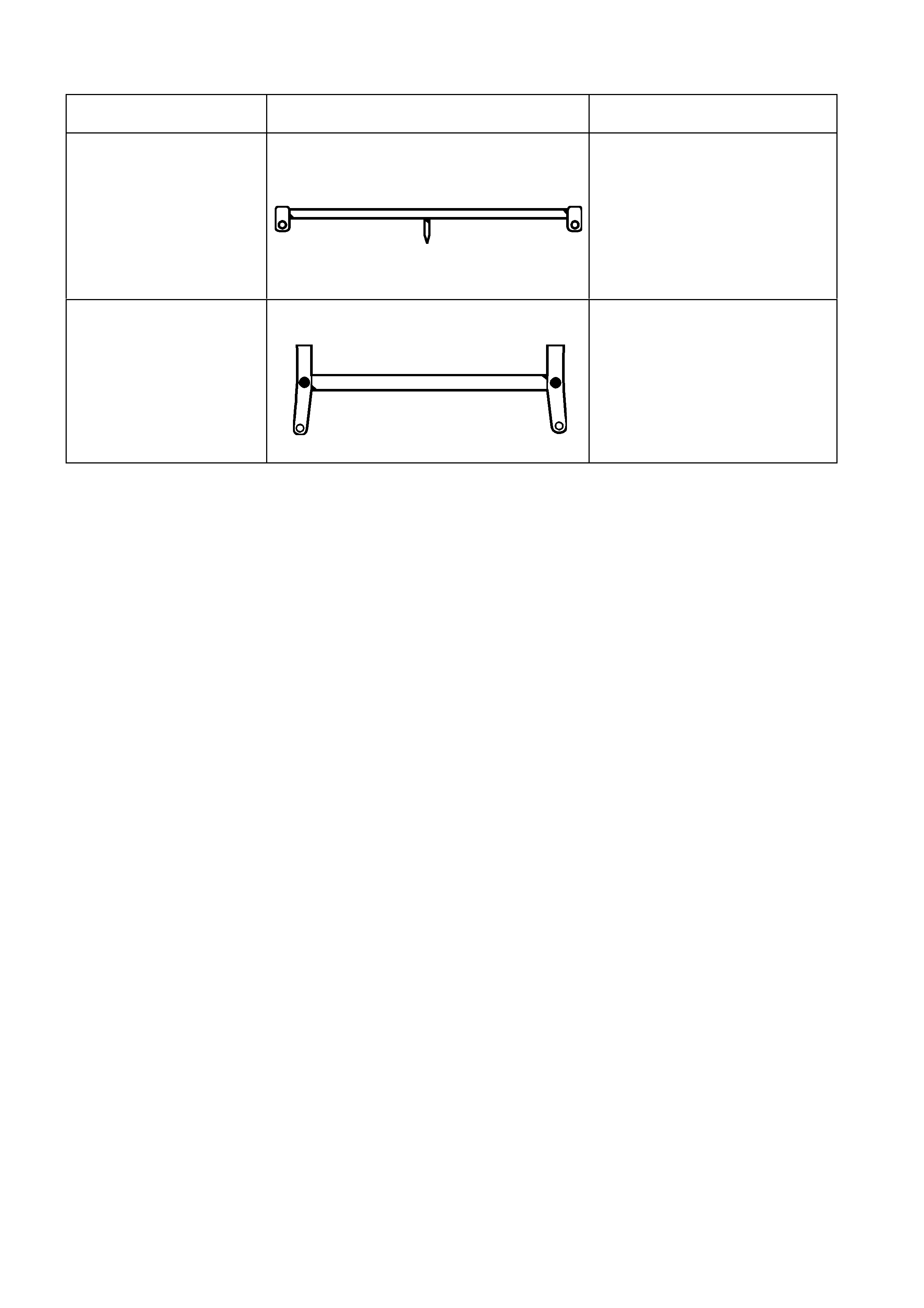
4. SPECIAL TOOLS
TOOL NO. REF IN TEXT TOOL DESCRIPTION COMMENTS
AU 457 FRONT CROSSMEMBER CENTRING
TOOL PREVIOUSLY RELEASED
AU 458 REAR CROSSMEMBER CENTRING TOOL
PREVIOUSLY RELEASED