SECTION 1A3 - INSTRUMENT PANEL
AND CONSOLE
IMPORTANT
Before performing any Service Operation or other procedure described in this Section, refer to Section
00 CAUTIONS AND NOTES for correct workshop practices with regard to safety and/or property damage.
1 SERVICE. OPERATIONS
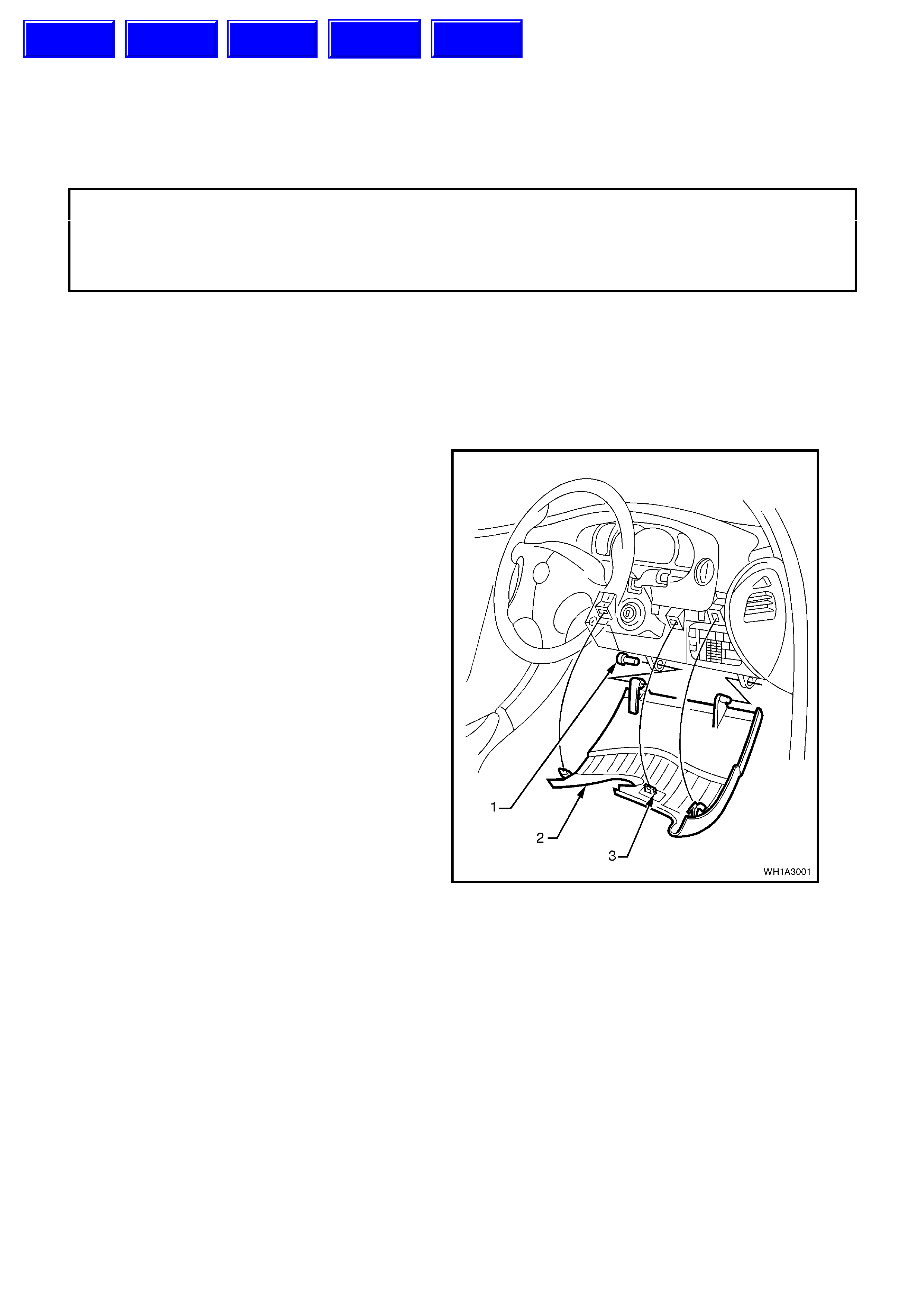
1.1 INSTRUME NT P ANEL LOWER COVER - RIGHT SIDE
REMOVE
1. Adjust steering wheel to upper most position.
Grasp right hand side of lower cover panel (2)
firmly and pull towards rear of vehicle
disengaging locating clips (3). Repeat
procedure for left hand side of cover. Prise out
the left hand hinge pin (1) using a flat blade
screwdriver.
Tilt the cover down on the left side and
disengage the right hand hinge pin and r em ove
panel.
Figure 1A3-1
REINSTALL
Reverse removal operations ensuring that locating
clips (3) are correctly aligned and securely engaged.
Techline
Techline
Techline
Techline
Techline
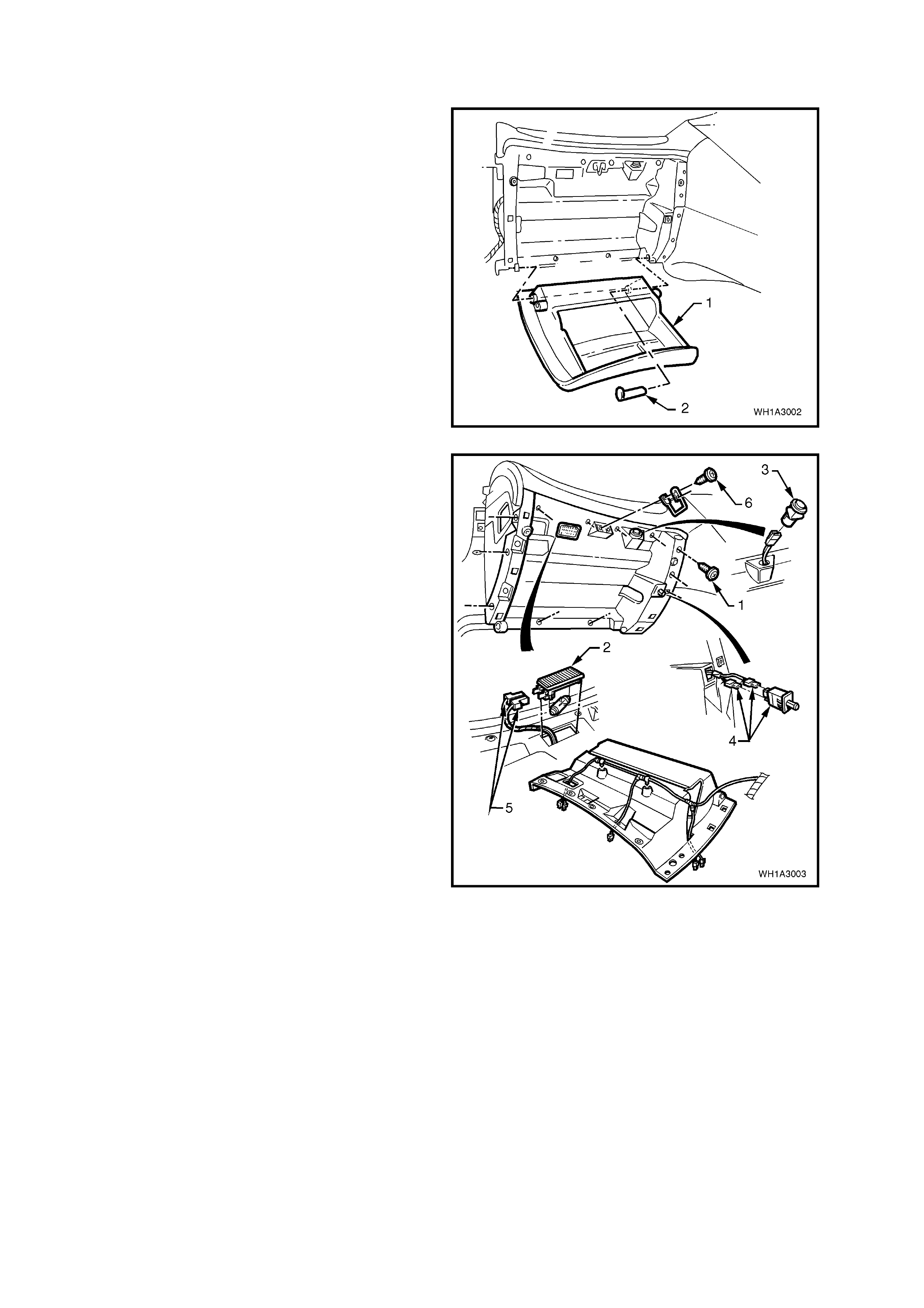
1.2 INSTRUMENT PANEL COMPARTMENT
REMOVE
1. Open the instrument panel lower compartment
(1) and lever the hinge pin (2) from the right
side. Lower compar tm ent and withdraw the pin.
Disengage travel limiting pegs by tilting
instrument panel lower compartment.
Figure 1A3-2
2. Disconnect instrument panel lamp connectors,
trunk lock switch connector, instrument panel
compartment switch connectors.
3. Remove retaining screws from instrument
compartment roof (1) and screw securing
Instrument facia side extension to console,
unclip glove box wiring harness, remove
instrument compartment roof.
Legend
1. Screw (11 places).
2. Instrument Panel compartment lamp.
3. Rear Compartment Lock release switch).
4. Instrument Panel compartment switch and
connectors.
5. Instrument Panel compartment lamp
connectors.
6. Screw (2 places).
Figure 1A3-3
REINSTALL
Reinstallation is the reverse of removal procedures.
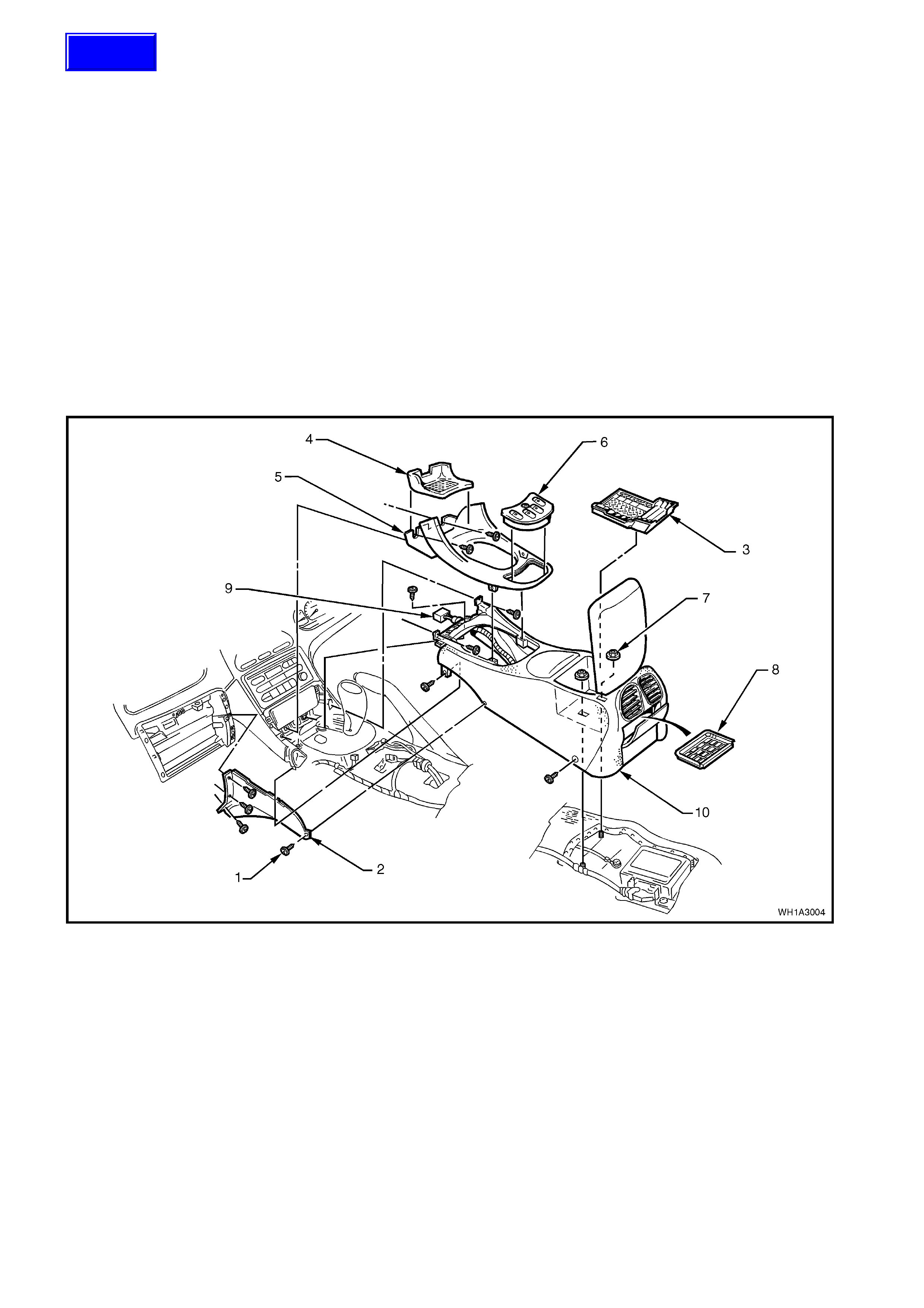
1.3 CENTRE CONSOLE
REMOVE
1. Slide seats rear ward, rem ove sc rews sec uring centre f acia side ex tensions and rem ove c entre facia side
extensions.
NOTE: There are four screws for the left-hand side extension and three screws for the right-hand side
extension.
2. Remove four screws securing centre console to transmission tunnel. Slide front seats forward to gain
access to rear screws.
3. From inside centre console bin remove rubber insert (3). Remove two console retaining nuts (7).
4. Remove rubber cap (4) from transmission console cap (5) and remove two securing screws, prise out
transmission console cap and disconnect window harness from power window switch assembly (6).
5. Remove two screws attaching storage compartment to instrument console and remove storage
compartment.
6. Remove two screws securing front of console to centre facia.
7. Partially remove centre console and disconnect wiring harness to centre console wiring connector (9).
Fully remove centre console (10) by lifting rear end up and pulling assembly out.
Figure 1A3-4
Legend
1. Screw (11 places).
2. Centre facia side extension (left side shown).
3. Insert.
4. Rubber cap.
5. Transmission console cap.
6. Power window switch assembly.
7. Nut (2 places).
8. Insert.
9. Console wiring harness connector.
10. Centre console.
REINSTALL
Reinstallation is the reverse of removal operations.
Techline
1.4 INSTRUME NT P ANEL FACIA
REMOVE
1. Remove rubber insert from transmission
console cap and remove two screws securing
transmission console to instrument panel
centre facia. Prise out transmission console
cap from centre console, disconnecting wiring
harness from power window switch. Refer to
1.3 CENTRE CONSOLE in this Section.
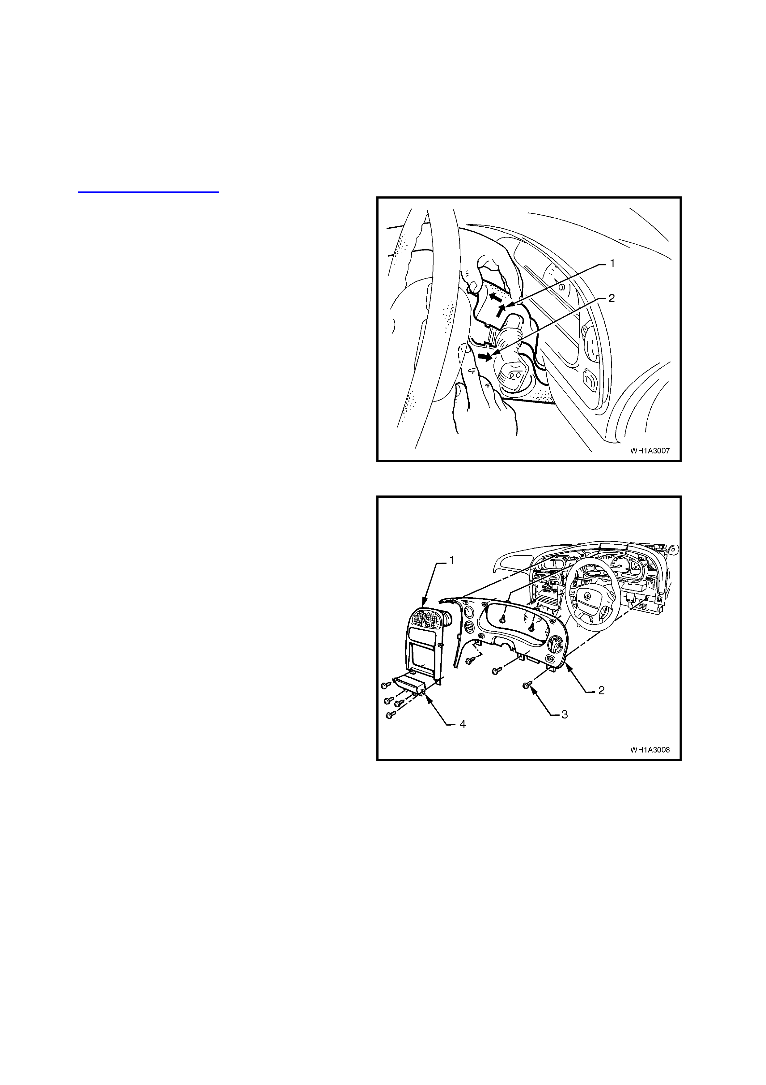
2. Remove single screw from the lower steering
colu mn cover.
3. Remove upper and lower steering covers.
Legend
1. Pull upper cover in this direction.
2. Push lower cover in this direction.
Figure 1A3-5
4. Lower instrument panel lower cover, remove
screws (3) retaining the instrument facia and
instrument facia storage compartment
assembly (4).
5. Remove ins trument f acia storage com partm ent
and pull instrument facia escutcheon (1) from
retaining clips.
6. Remove instrument facia (2) by pulling facia
from retaining clips.
NOTE: Care m ust be taken to dis connect the m ain
wiring harness connector from the headlamp
switch, fog lamp switch, trip com puter switch, clock
and hazard switch.
Figure 1A3-6
REINSTALL
Reinstallation is the reverse of removal pr ocedures
ensuring all harnesses are reconnected prior to
attaching facia to retaining clips and reinstalling
seven retaining screws.
1.5 INSTRUMENT PANEL CENTRE FACIA ASSEMBLY
REMOVE
1. Remove instrument panel facia, refer to
1.4 INSTRUMENT PANEL FACIA in this
Section.
2. Remove instrument panel compartment roof,
refer to 1.2 INSTRUMENT PANEL
COMPARTMENT in this Section.
3. Remove left hand centre facia side extension,
refer to 1.3 CENTRE CONSOLE in this
Section.
4. Unclip antenna leads from inboard end of
glovebox lower rail.
NOTE: This is necessary to provide enough
antenna cable to pull radio forward.
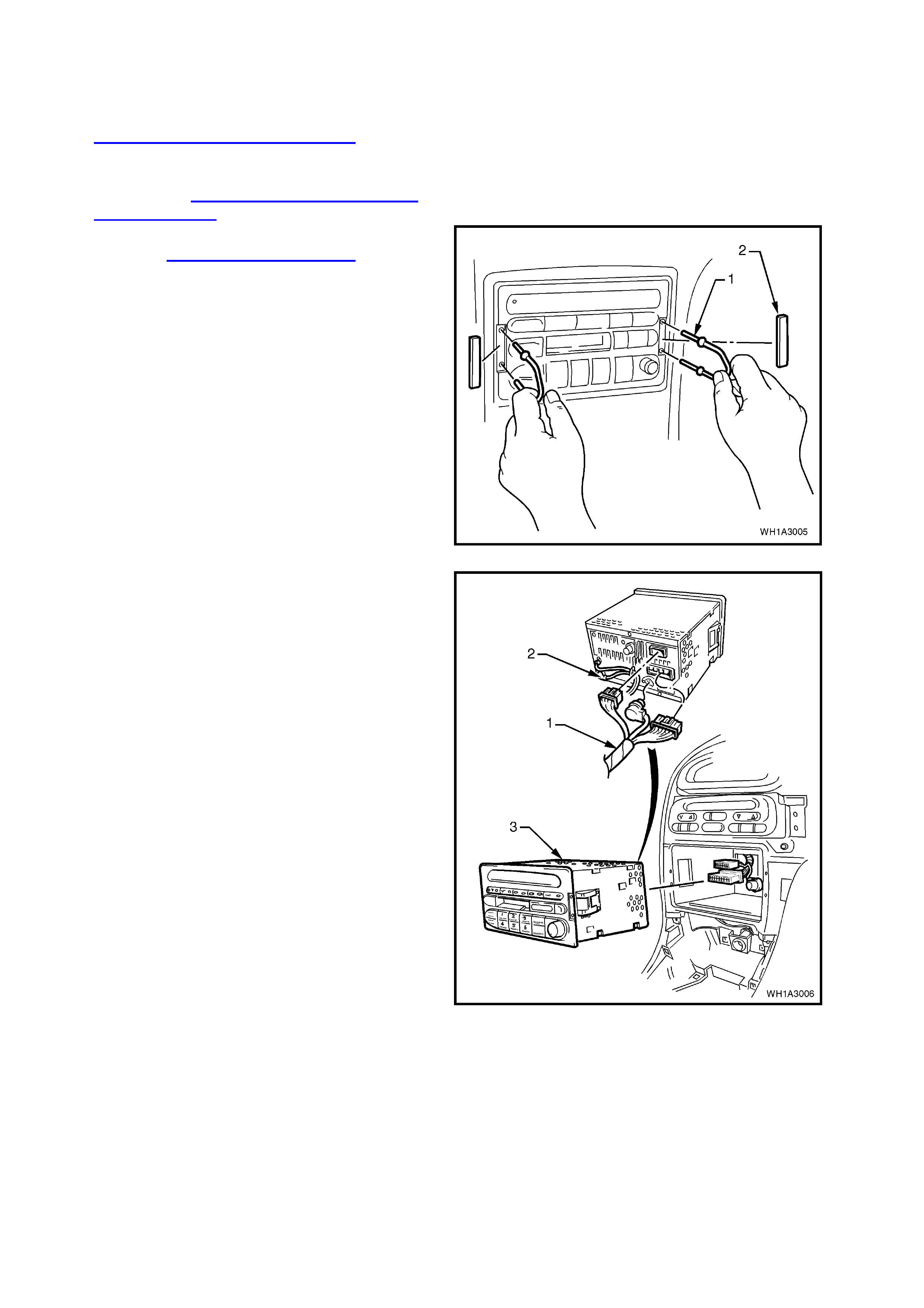
5. Remove service tool hole covers (2) and
remove radio/cassette/CD from instrument
panel using service tool 179 1308 0000 (1).
Figure 1A3-7
6. Disconnect radio/cassette harness and CD
connector (2). Disconnect antenna and
diversity antenna connectors (1) from rear of
radio/cassette/CD player (3).
Figure 1A3-8
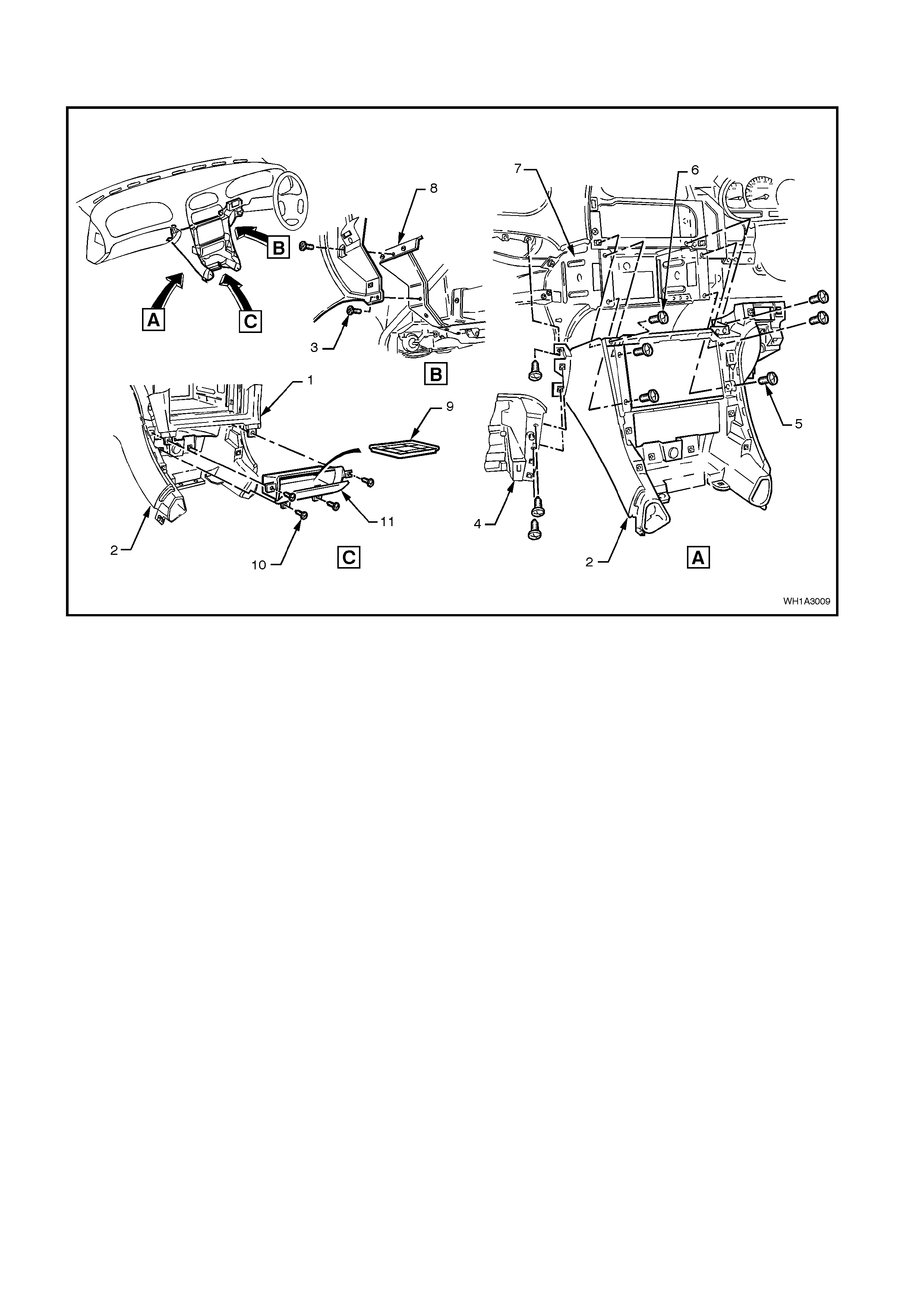
7. Remove screws securing centre facia to
instrument panel carrier and remove centre
facia assembly.
Figure 1A3-9
Legend
1. Instrument facia escutcheon.
2. Instrument panel centre facia assembly.
3. Screw (2 places).
4. Instrument panel compartment roof.
5. Screw (4 places).
6. Screw (2 places).
7. Instrument panel carrier rail.
8. Instrument panel centre facia side extension support.
9. Insert.
10. Screw (4 places).
11. Instrument Console storage compartment.
REINSTALL
Reinstallation is the reverse of removal
procedures.
NOTE: Ensure antenna c ables are pulled bac k into
position and re attached to lower rail.
1.6 INSTRUMENT PANEL PAD ASSEMBLY
REMOVE
CAUTION: Disable the SRS (Air Bag). Refer to
DISABLING THE SRS, Section 00 CAUTIONS
AND NOTES.
1. Disconnect battery ground cable.
2. Remove instrument panel lower cover - right
side, instrument panel compartment, centre
console and instrument panel facia, refer to
1.1, 1.2, 1.3 and 1.4 in this Section.
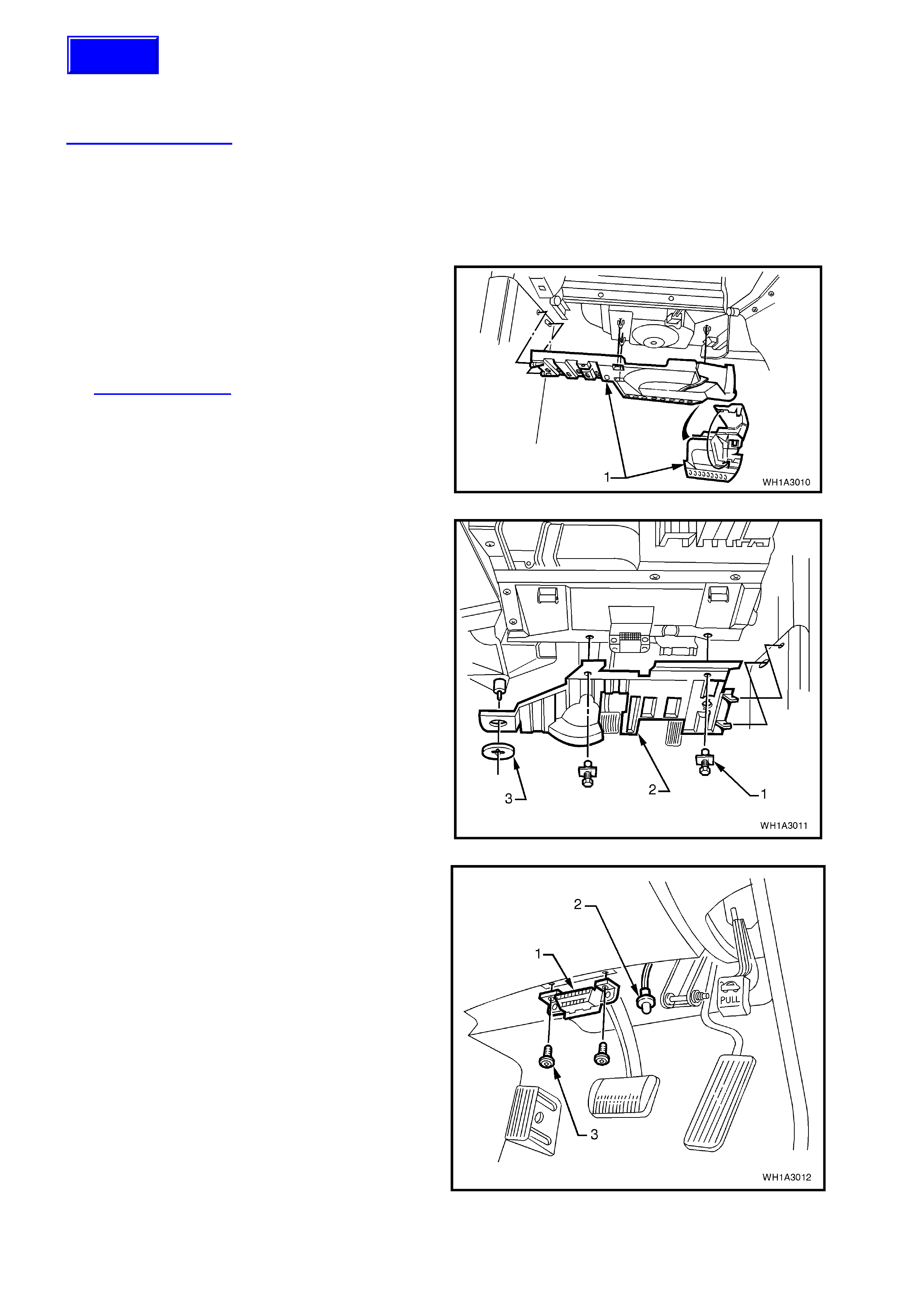
3. Disengage footwell upper closing panel (1)
locating lugs to passenger side shroud lower,
detach by pulling left side down first, then
disengage right side clip and remove panel.
4. Remove passenger side shroud lower trim
assembly, for further information refer to
Section 1A1 BODY.
Figure 1A3-10
5. Remove two scrivets (2), prise off retaining
button (3) and detach the footwell upper closing
panel right side (2).
Disconnect front footwell lamp from closing
panel.
Figure 1A3-11
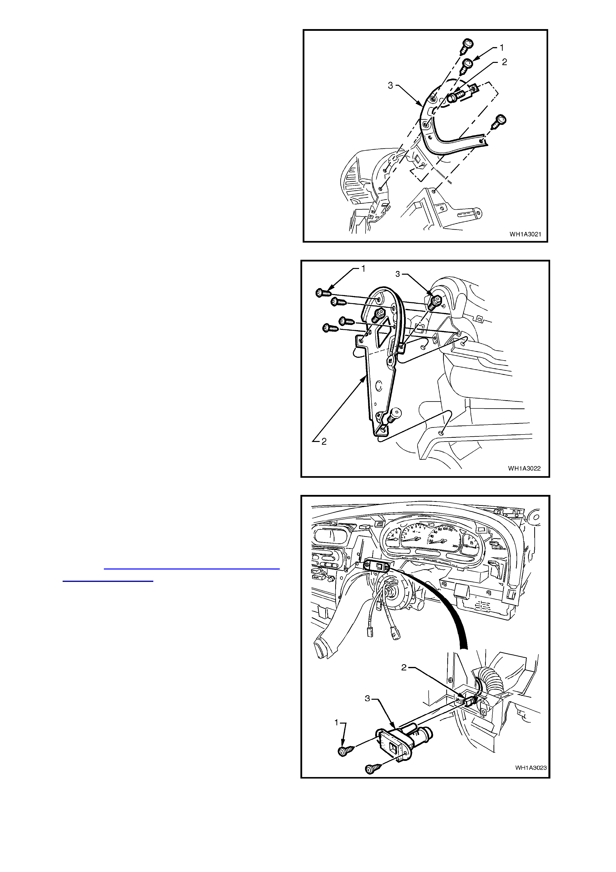
6. Remove two screws (3) securing diagnostics
connector (1) to instrument panel lower trim
right side assembly.
Figure 1A3-12
Techline
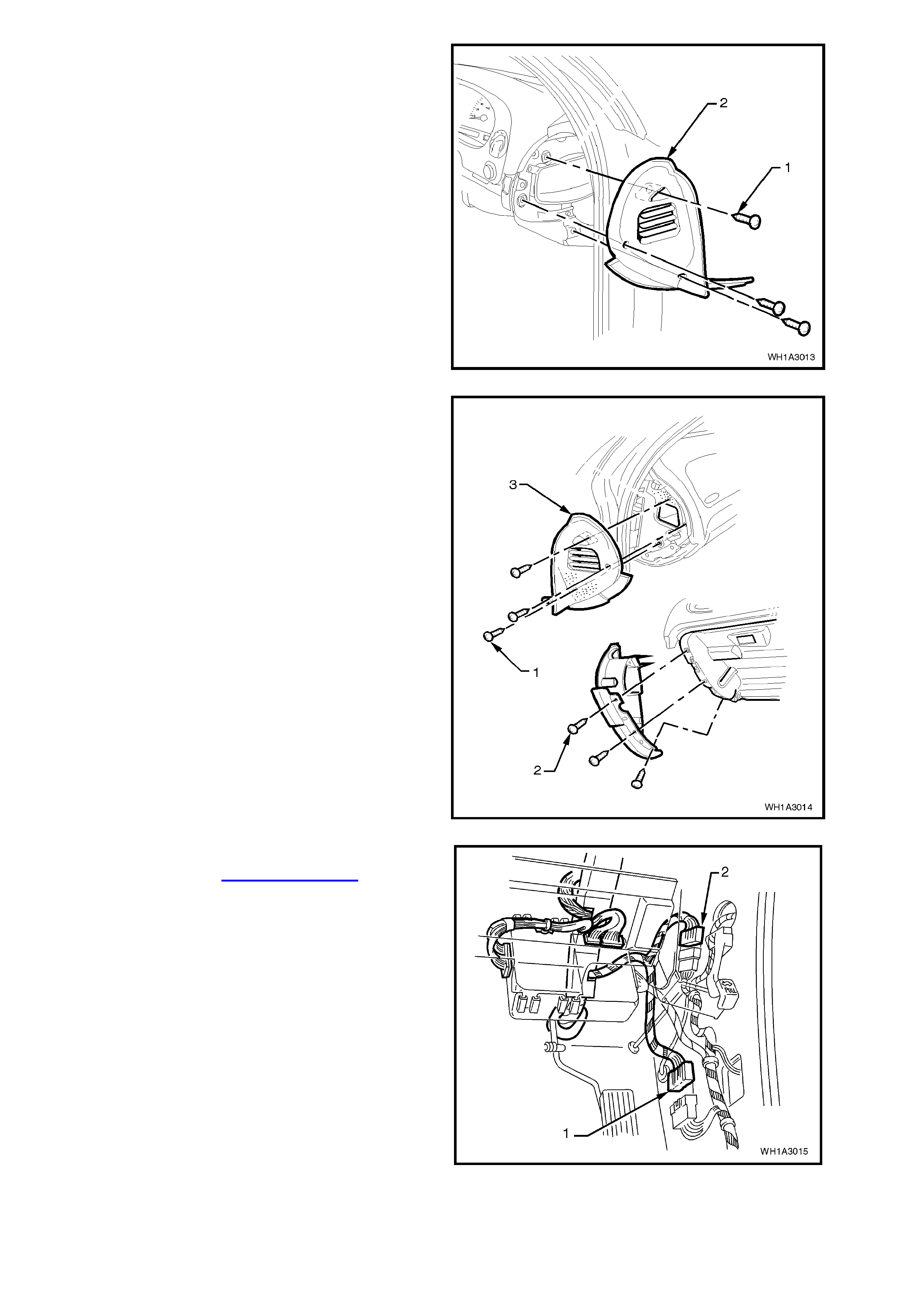
7. Remove three screws (1) and remove
instrument panel end cap cover (2) right hand
side.
Figure 1A3-13
8. Remove six retaining screws (1 and 2) for
instrument panel end cap cover left hand side
(3).
Figure 1A3-14
9. Remove driver’s side shroud lower trim
assembly, refer to Section 1A1 BODY.
10. Separate the body harness and main wiring
harness connectors (1and 2).
Figure 1A3-15
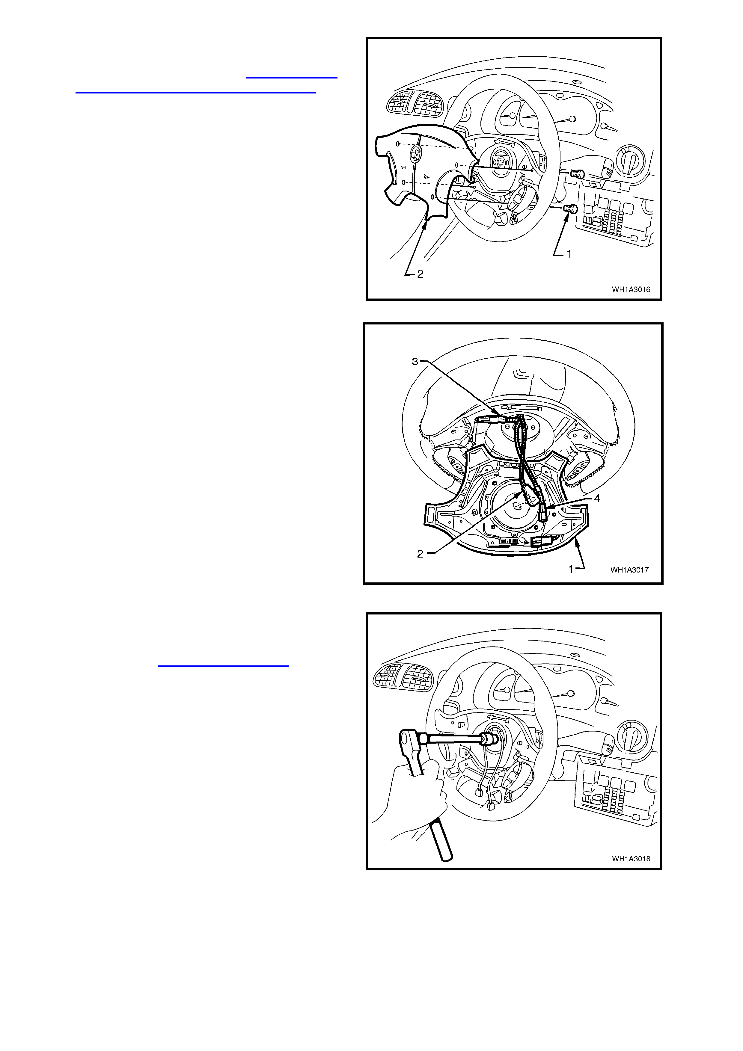
11. Remove four retaining screws (1) securing
horn bar and air bag assembly to steering
wheel (2) refer to Section 12M
SUPPLEMENTARY RESTRAINT SYSTEM.
Figure 1A3-16
12. Lift up horn bar and air bag inflator module
assembly (1) from the steering wheel, remove
the yellow clock spring to inflator assembly
connection (2) and disconnect wiring harness
connectors (3 and 4) from rear of assembly.
NOTE: If removing a horn bar and air bag inflator
module assembly from a steering wheel fitted with
stereo controls (as shown), take extreme care
when disconnecting the left hand horn pad
connector (3) from the stereo control wiring
connector otherwise damage to the stereo control
wiring could result.
13. Remove horn bar and air bag inflator module
assembly.
Figure 1A3-17
14. Using a commercially available Torx E20
socket, remove single screw securing steering
wheel to steering column, and rem ove steering
wheel, refer to Section 9A STEERING.
Figure 1A3-18
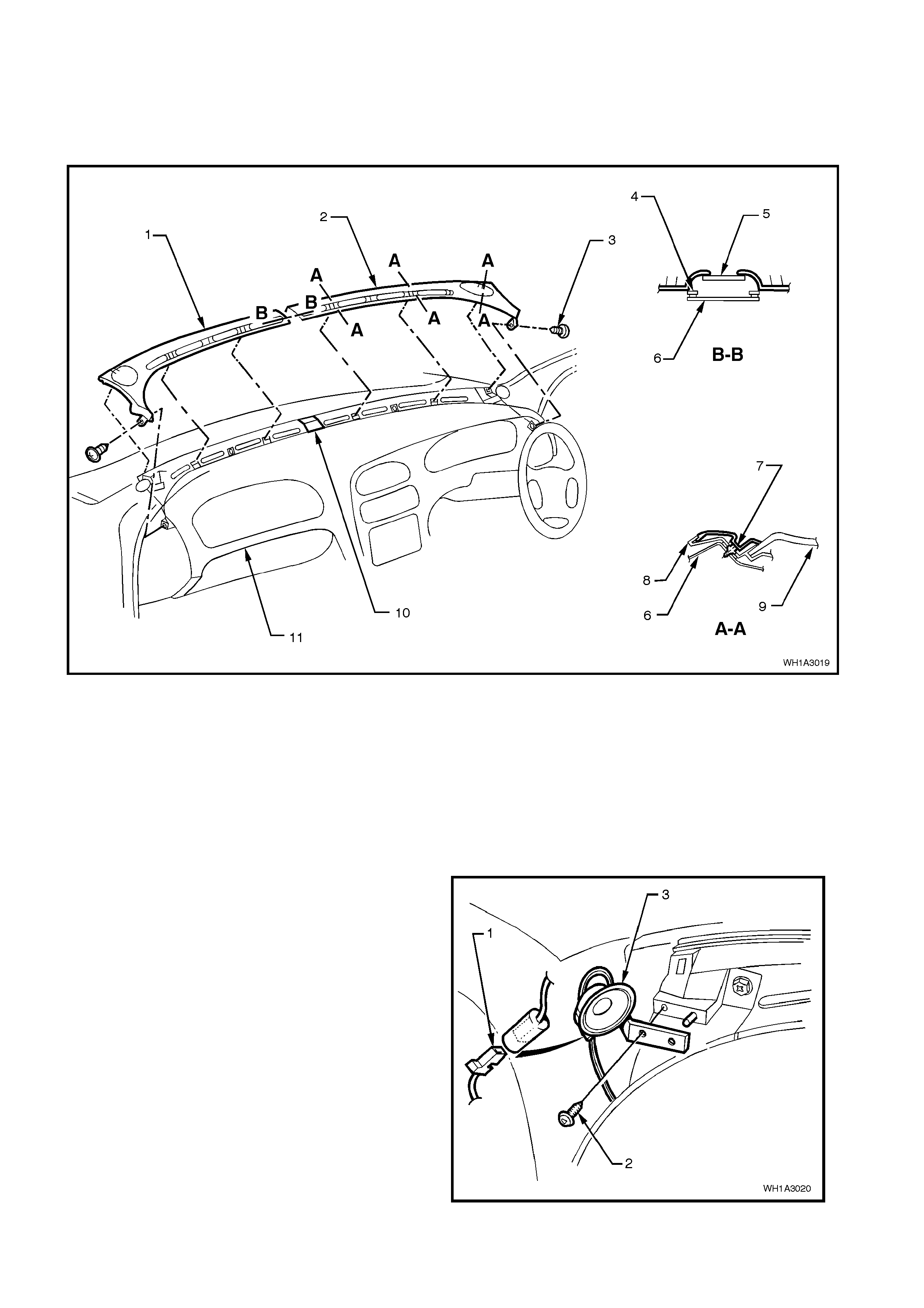
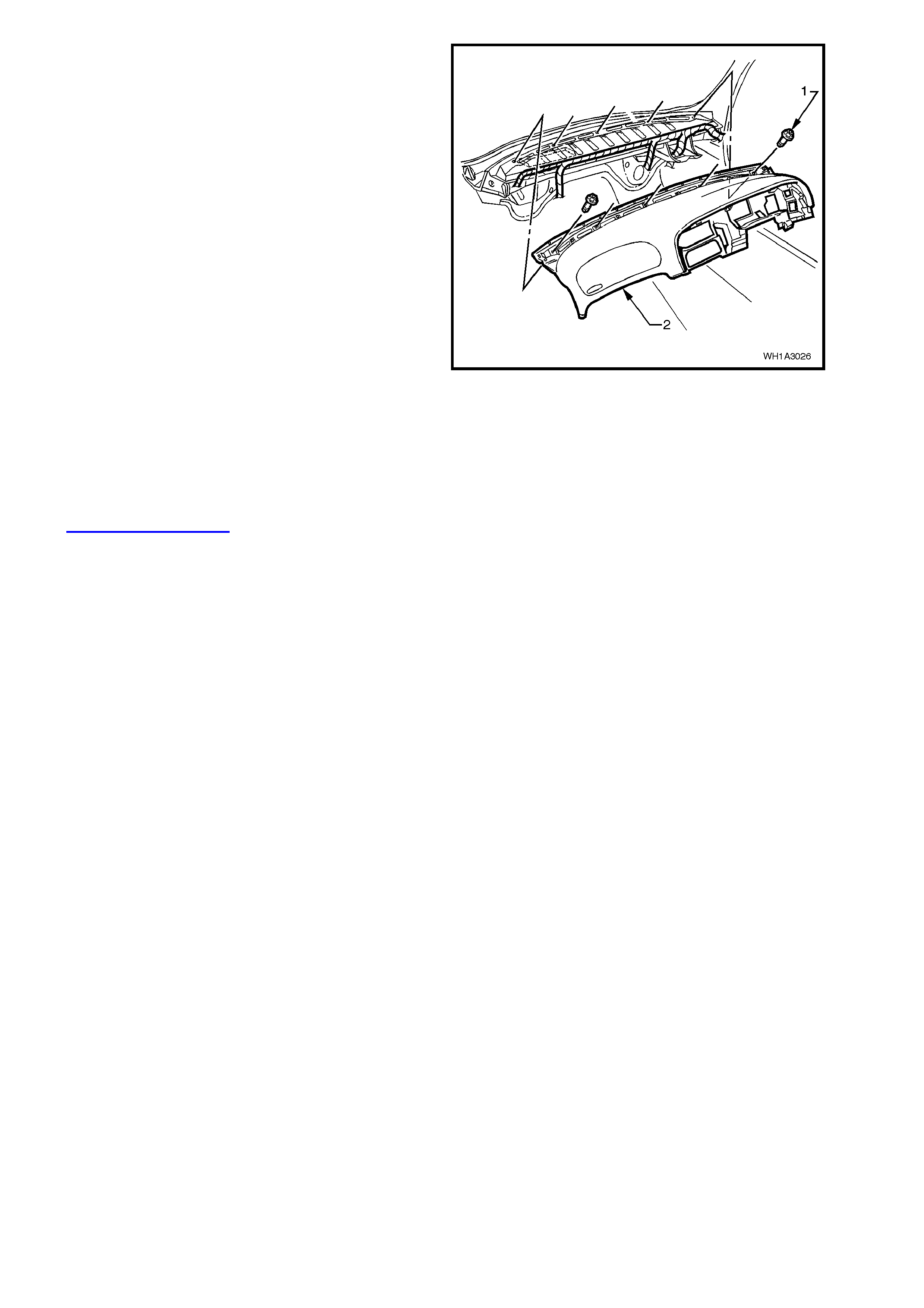
15. Remove retaining screw (3) from the demist
nozzle grille right hand (2) and remove.
16. Remove retaining screw from the demist nozzle
grille left hand (1) and remove.
NOTE: Care m ust be taken not to damage the sun
sensor when removing the demist nozzle grilles.
Figure 1A3-19
Legend
1. Demist nozzle grille left hand side.
2. Demist nozzle grille right hand side.
3. Screw (1 place right and left side).
4. Instrument Panel Pad carrier.
5. Solar sensor.
6. Instrument Panel Pad carrier.
7. Tabs to be inserted into holes in instrument panel
pad carrier before installation of right and light side
attaching screws.
8. Demist grille seal.
9. Instrument panel upper pad assembly.
10. Solar sensor.
11. Instrument panel pad assembly.
17. Disconnect left and right front dash speaker
harness connectors (1). Using a Phillip’s screw
driver, remove screw (2) attaching front dash
speakers (3) and remove both speakers.
Figure 1A3-20
18. Remove three retaining screws (1) and one bolt
(2) from instrument panel carrier end panel
right side (3) and remove panel.
Figure 1A3-21
19. Remove four attaching screws (1) securing
instrument panel carrier end panel left side (2)
and two bolts (3) attaching passenger air bag
support rail, lower left side rail, and remove
panel.
Figure 1A3-22
20. Remove the attaching screws (1) securing in-
car sensor (3) and disconnect harness
connector (2).
21. Remove the screws securing centre facia
assembly and remove centre facia assembly,
refer to 1.5 INSTRUMENT PANEL CENTRE
FACIA ASSEMBLY in this Section.
Figure 1A3-23

22. Remove ECC control unit.
Legend
1. Screw (2 places).
2. HVAC connector.
3. ECC connector.
4. Radio/Cassette/CD connectors.
5. Auxiliary power socket.
6. ECC Module.
7. Locating pins must be aligned with carrier
during installation.
Figure 1A3-24
23. Remove the screws (1) securing the combined
instruments assembly (2) and disconnect
instruments connector (3).
Figure 1A3-25

2. TORQUE WRENCH SPECIFI CATIONS
Nm
Instrument panel compartment attaching screws................. 1 - 3
Instrument panel compartment lock striker attaching screws 1 - 3
Centre console securing screws........................................... 1 - 3
Centre console bin retaining nuts ......................................... 3 - 5
Transmission console retaining screws................................ 1 - 3
Screws securing transmission console cap
to instrument panel ............................................................... 1 - 3
Lower steering column shroud screw ................................... 0.5 - 2
Instrument facia assembly retaining screws......................... 1 - 3
Storage compartment retaining screws................................ 1 - 3
Centre facia assembly securing screws ............................... 1 - 3
Diagnostics connector attaching screws............................... 1 - 2
Instrument panel end cap cover attaching screws................ 1 - 3
Airbag securing screws......................................................... 8 - 11.3
Steering wheel securing screw............................................. 40 - 50
Demist nozzle retaining screws ............................................ 1 - 3
Front dash speaker connecting screws................................ 1 - 2
Instrument panel carrier end panel attachment screws........ 1 - 3
Instrument panel carrier panel attaching bolts...................... 3 - 5
In-car sensor attaching screws............................................. 1 - 3
ECC control securing screws................................................ 1 - 3
Combined instruments assembly securing screws............... 1 - 3
Instrument panel carrier retaining screws............................. 7 - 12
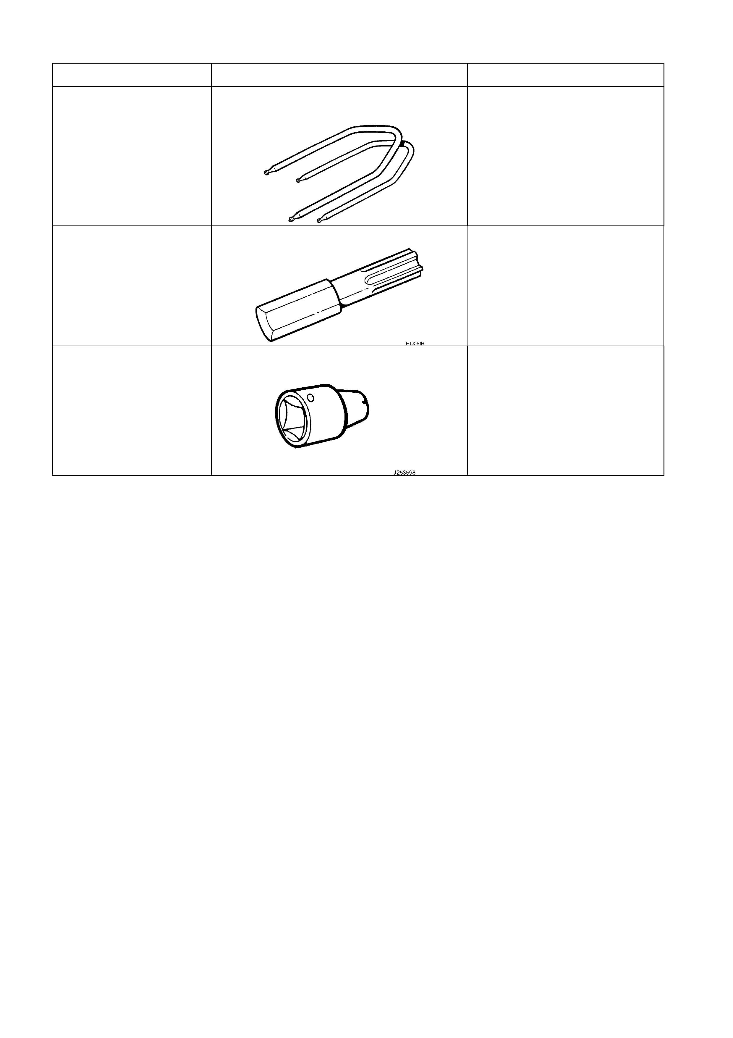
3. SPECIAL TOOLS
TOOL NO. REF IN TEXT TOOL DESCRIPTION COMMENTS
179 1308 0000 RADIO REMOVAL TOOL
ETX30H TORX BIT
J25359-8 TORX BIT HOLDER