SECTION 1A4 - REAR COMPARTMENT LID
IMPORTANT
Before performing any Service Operation or other procedure described in this Section, refer to Section
00 CAUTIONS AND NOTES for correct workshop practices with regard to safety and/or property damage.
1. SERVICE OPERATIONS
1.1 REAR COMPARTMENT LID ASSEMBLY
REMOVE
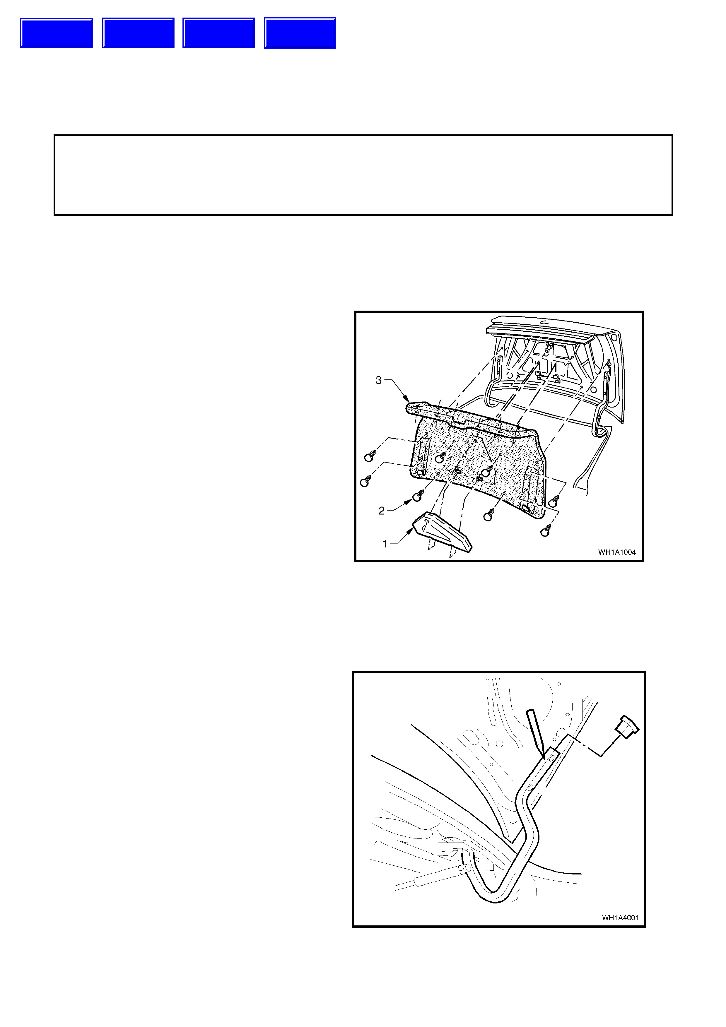
1. Remove the safety triangle (1) from its position
in the rear compartment lid.
2. Remove the sixteen retainers (2) securing the
carpet assembly (3) to the rear compartment
lid.
3. Move the carpet assembly from its position on
the rear compartment lid, open the hinge slots
at the base of the c arpet ass em bly and rem ove
the carpet.
4. Remove two screws securing latch to rear
compartment lid and disconnect emergency
release cable from latch.
5. Remove screw securing outer emergency
release cable retaining bracket and push
bracket locating pin from hole.
6. Withdraw emergency release cable from rear
compartment lid.
7. Disconnect wiring harness connectors from
rear compartment lid lock actuator, reversing
lamps (where fitted in rear compartment lid
decor trim) and withdraw harness(es) from
compartment lid.
Figure 1A4-1
8. With the rear compartment lid raised, pencil
scribe location of hinges on the lid inner panel
to facilitate installation.
9. With the lid supported, remove the hinge-to-lid
attaching bolts, removing the lid assembly.
Figure 1A4-2
Techline
Techline
Techline
Techline

REINSTALL
Reverse removal operations.
REAR COMPARTMENT LID ATTACHING
BOLT TORQUE SPECI F ICATION 6-14
Nm
ADJUST
Elongated holes in the hinges provide forward and
rearward adjustment of the lid. Vertical height
adjustment at the hinge area of the lid can be
achieved as follows.
To raise the lid at the hinge area, place a shim
between the lid inner panel and hinge at the
forward attaching bolt hole location.
NOTE: Following any adjustment of the rear
compartment lid, it is essential that the lid latch
striker engages correctly with the lid latch. Adjust
the striker to ensure positive engagement of the
latch and to achieve corr ect alignment between the
rear com par tment lid and adjacent panels , refer 1.4
LATCH STRIKER – REAR COMPARTMENT LID
in this Section.
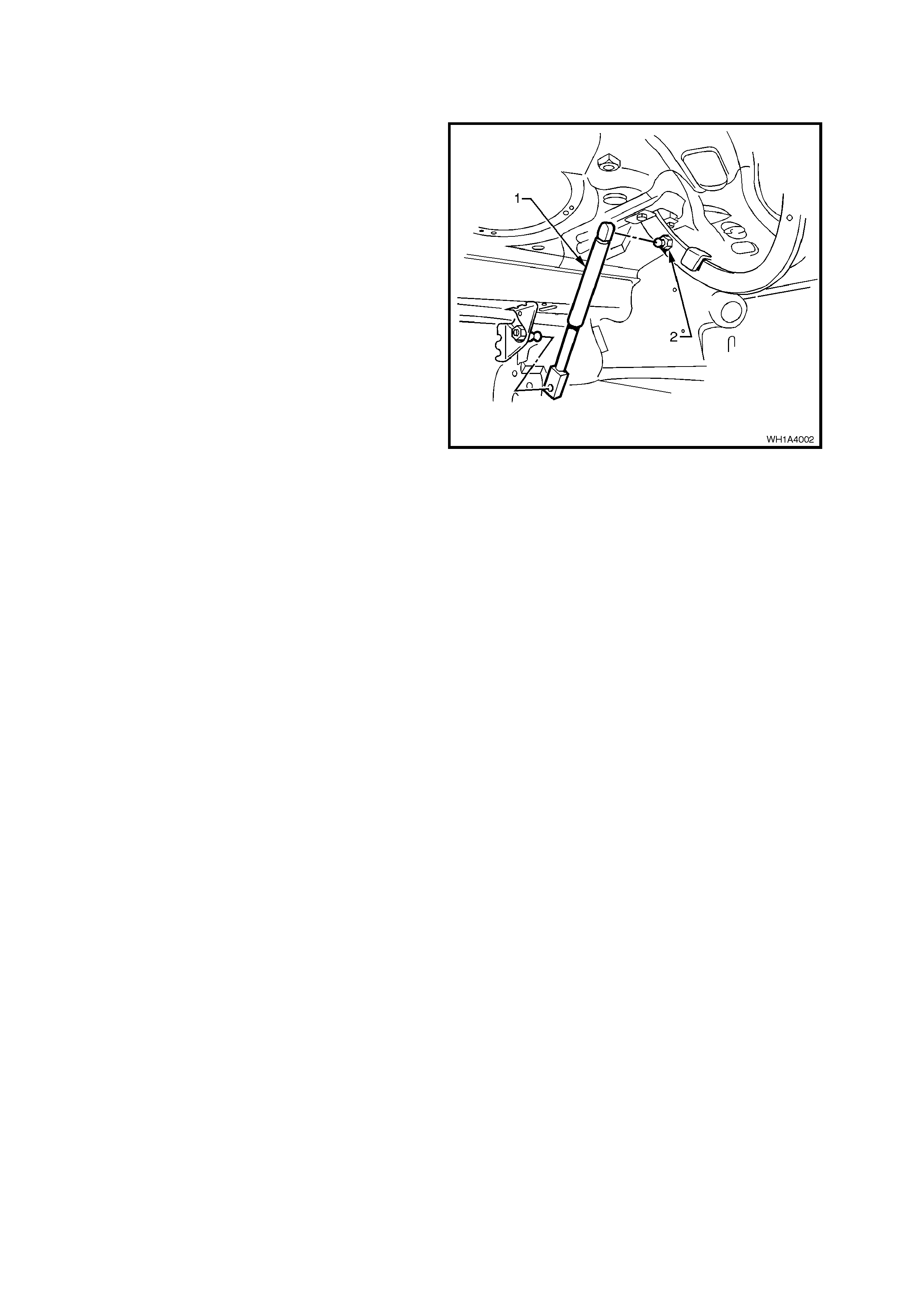
1.2 GAS STRUT - REAR COMPARTMENT LID
REMOVE
1. Raise and support the rear compartment lid.
2. Using a thin bladed screwdriver located under
the gas strut ball pivot spring, prise the spring
open. This will allow the strut (1) to be pulled
off the ball pivot (2).
Figure 1A4-3
REINSTALL
Reverse removal operations.
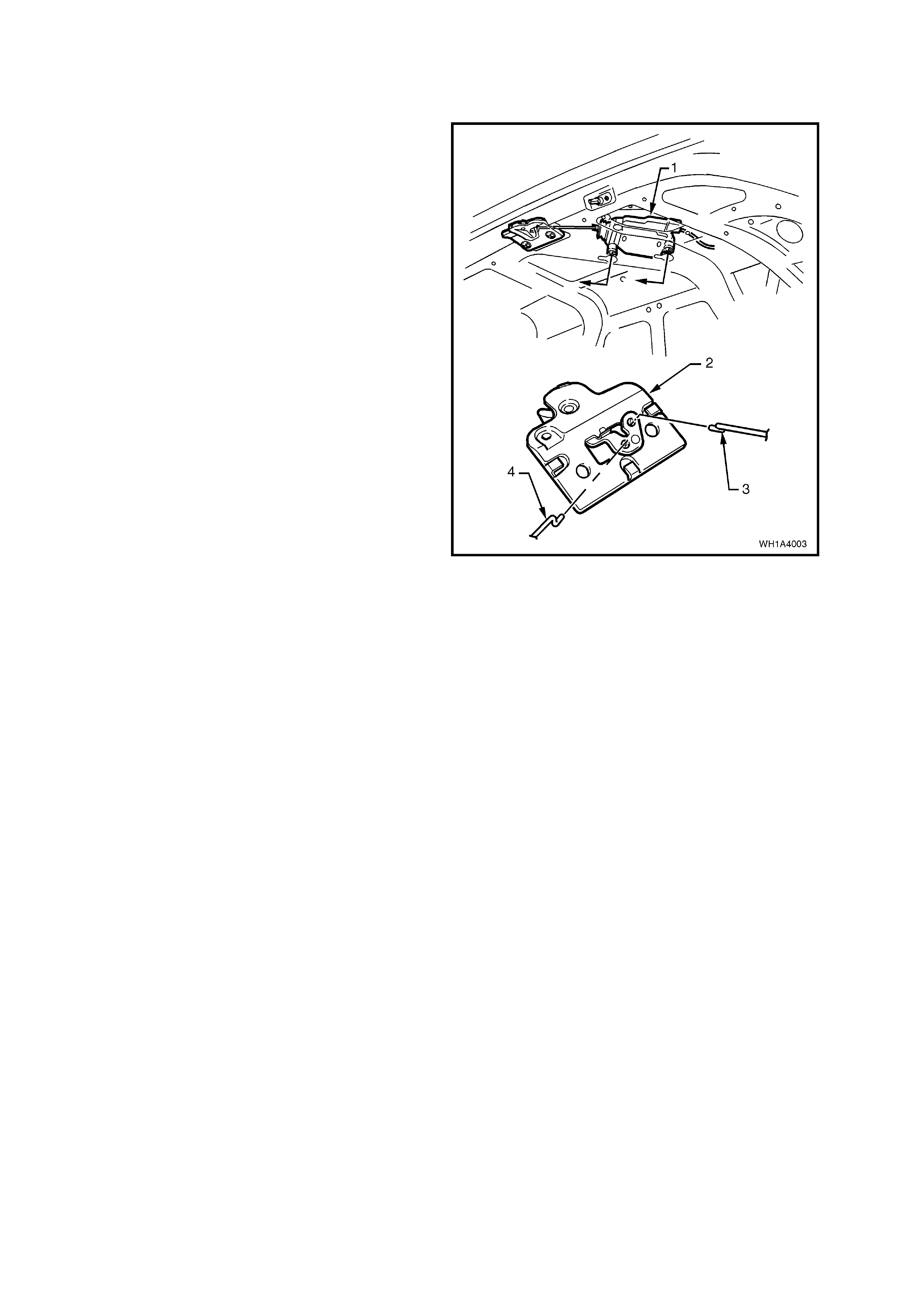
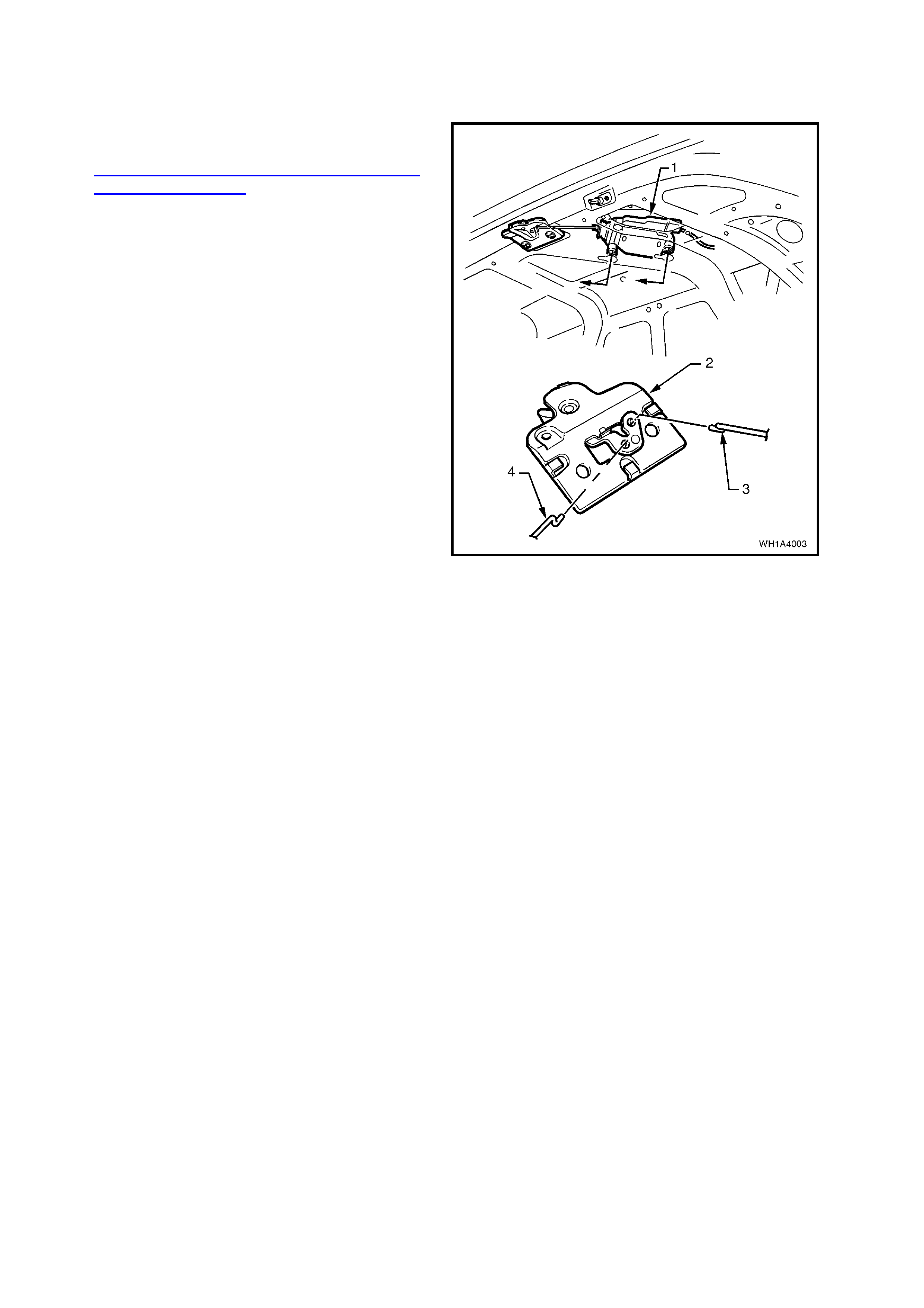
1.3 LATCH ASSEMBLY - REAR COMPARTMENT LID
REMOVE
1. Remove rear compartment lid liner carpet by
first removing the 16 fasteners.
2. With the rear compartment lid raised, remove
screws securing the latch assembly to the rear
compartment lid inner panel, disconnect cable
and actuator link.
Legend
1. Latch actuator.
2. Latch assembly.
3. Rod from actuator.
4. Cable from remote release.
Figure 1A4-4
REINSTALL
Reverse removal operations.
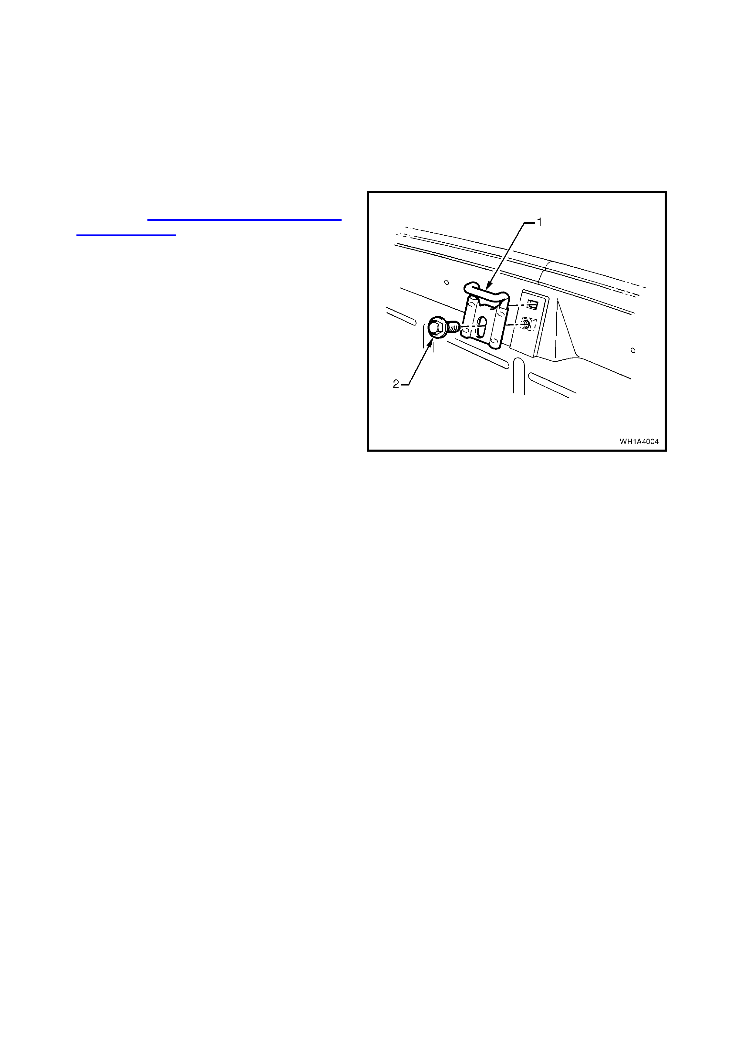
1.4 LATCH STRIKER - REAR COMPARTMENT LID
ADJUST
Loosen screw (2) retaining latch striker (1) and
reposition so striker engages correctly with the
latch assembly. Tighten screws before checking
adjustment.
REMOVE
1. Remove rear compartment crossmember
cover refer Section 1A8 HEADLINING AND
REAR END TRIM.
2 With the rear compartment lid raised, pencil
scribe location of the striker on the rear end
inner panel to facilitate installation.
3. Remove the screw (2) attaching the latch
striker (1) to the rear end inner panel and
remove the striker.
Figure 1A4-5
REINSTALL
Reverse removal operations.
NOTE: An elongated hole in the latch striker
provides adjustment for the striker. Following any
adjustm ent of the s triker or rear compartm ent lid, it
is essential that the lid latch correctly engages the
striker.
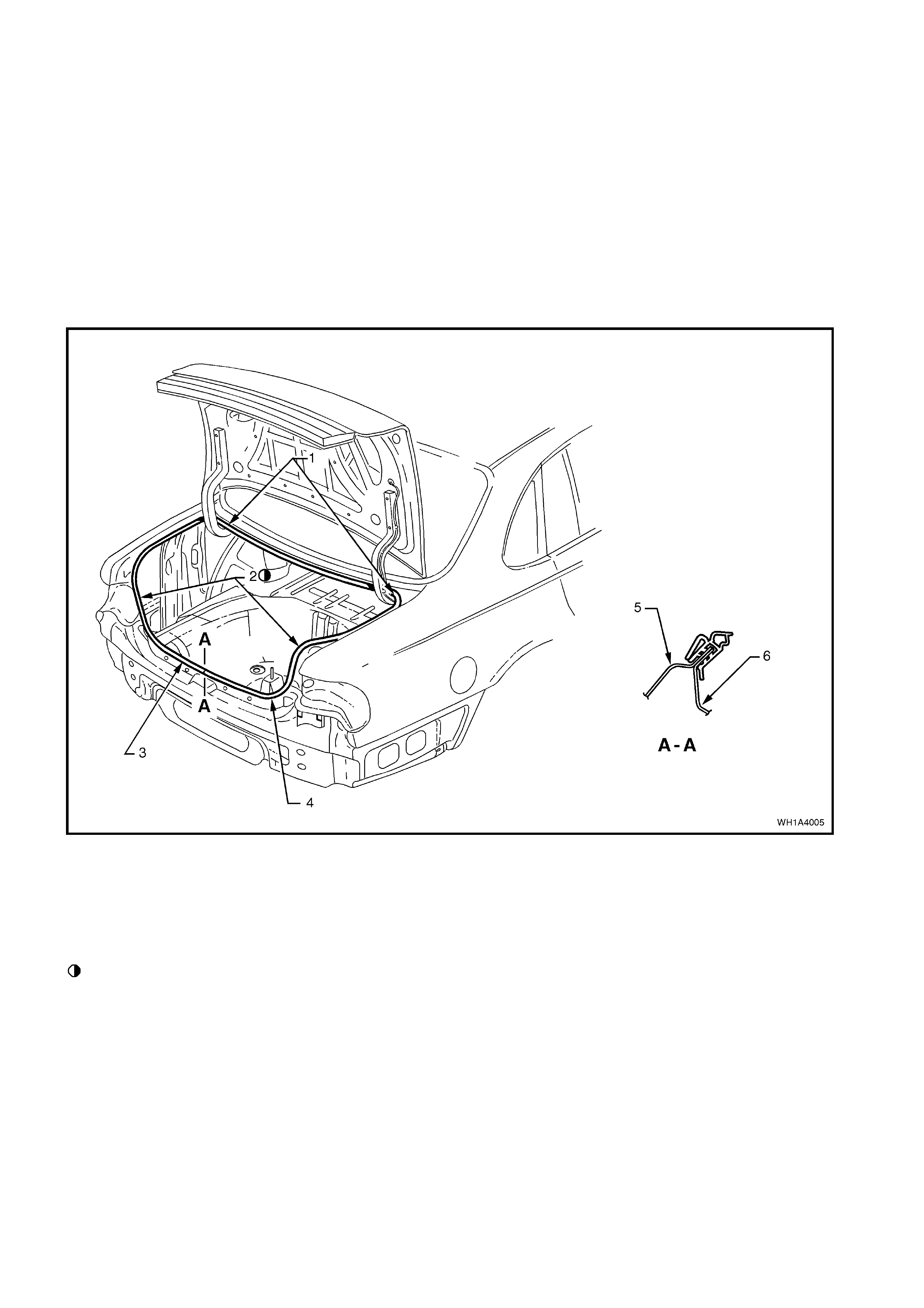
1.5 WEATHERSTRIP ASSEMBLY - REAR COMPARTMENT LID OPENING
DESCRIPTION
The one piece rear compartment lid opening
weatherstrip is a bulbous rubber ‘U’ section fitted
with an integral retaining system. It fits firmly over
the upturned flange of the rear compartment
opening.
NOTE: When installing the weatherstrip assembly,
locate the longer side of the ‘U’ section on the
outside of the rear compartment opening upturned
flange. Align weatherstrip ‘first notch’ with panel
join. Push weatherstrip onto rear compartment
opening flange.
Figure 1A4-6
Legend
1. Allow crowding of weatherstrip in all corners to
ensure weatherstrip does not short cut corners.
2. Datum control marks on weatherstrip Left and
Right.
Datum marks are ORANGE and line up with joint
between tail lamp pocket and side panel outer.
3. Ensure j oint of weatherstrip is centr ally located on
lower flange. Refer Section A-A.
4. Deck lid weatherstrip.
5. Back panel lower reinforcement.
6. Lower back panel.
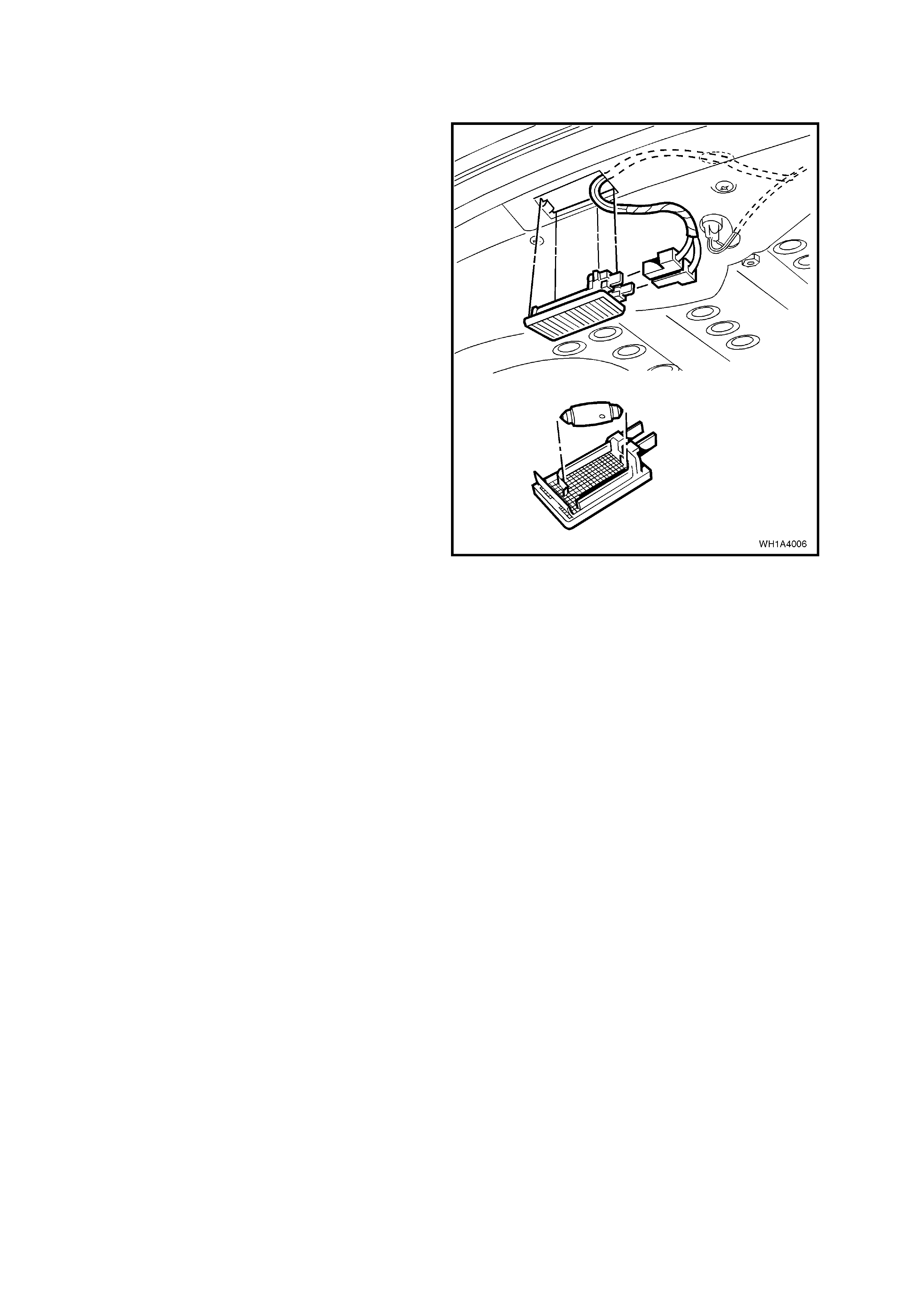
1.6 REAR COMPARTMENT LAMP ASSEMBLY
REMOVE
1. W ith the r ear com partm ent lid raised and us ing
the blade of a screwdriver located between the
lamp lens and rear compartment inner panel,
carefully prise the lamp assembly out of the
lamp aperture.
2. Disengage the electrical connector, removing
the lamp assembly.
Figure 1A4-7
REINSTALL
Reverse removal operations.
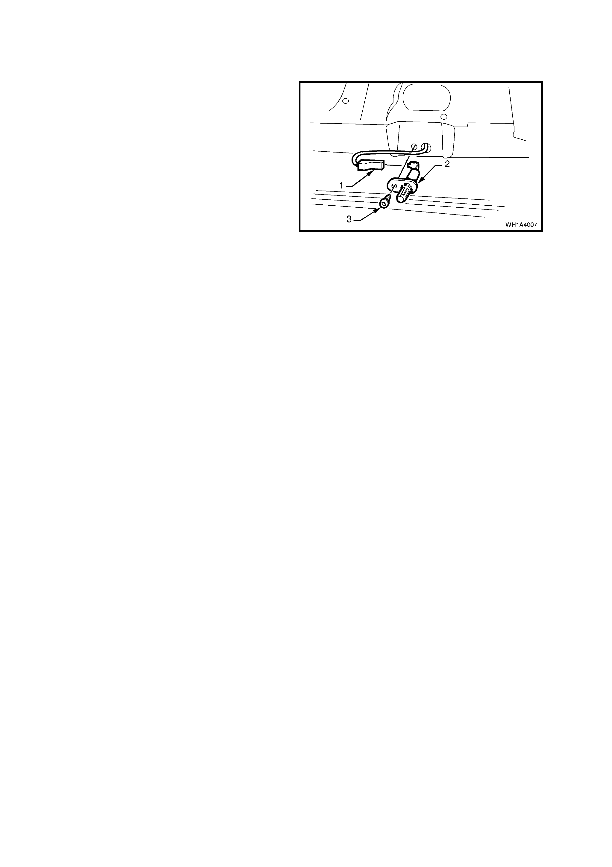
1.7 SWITCH ASSEMBLY - REAR COMPARTMENT LID LAMP
REMOVE
1. With the rear compartment lid raised, remove
the screw (3) securing the switch assembly (2)
to the rear compartment lid.
2. Disengage the electrical connector (1) and
remove the switch assembly.
Figure 1A4-8
REINSTALL
Reverse removal operations.
1.8 ACTUATOR ASSEMBLY - REAR COMPARTMENT LID LATCH
REMOVE
1. With the rear compartment lid raised remove
the rear compartment lid latch, refer to
1.4 LATCH ASSEMBLY - REAR
COM PARTMENT LID - SEDAN in this Section,
and disconnect the remote control actuator
actuating rod.
2. Remove the two screws securing the actuator
to the rear compartment lid, disconnect the
electrical connector, removing the actuator.
Legend
1. Latch actuator.
2. Latch assembly.
3. Rod from actuator.
4. Cable from remote release.
Figure 1A4-9
REINSTALL
Reverse removal operations.
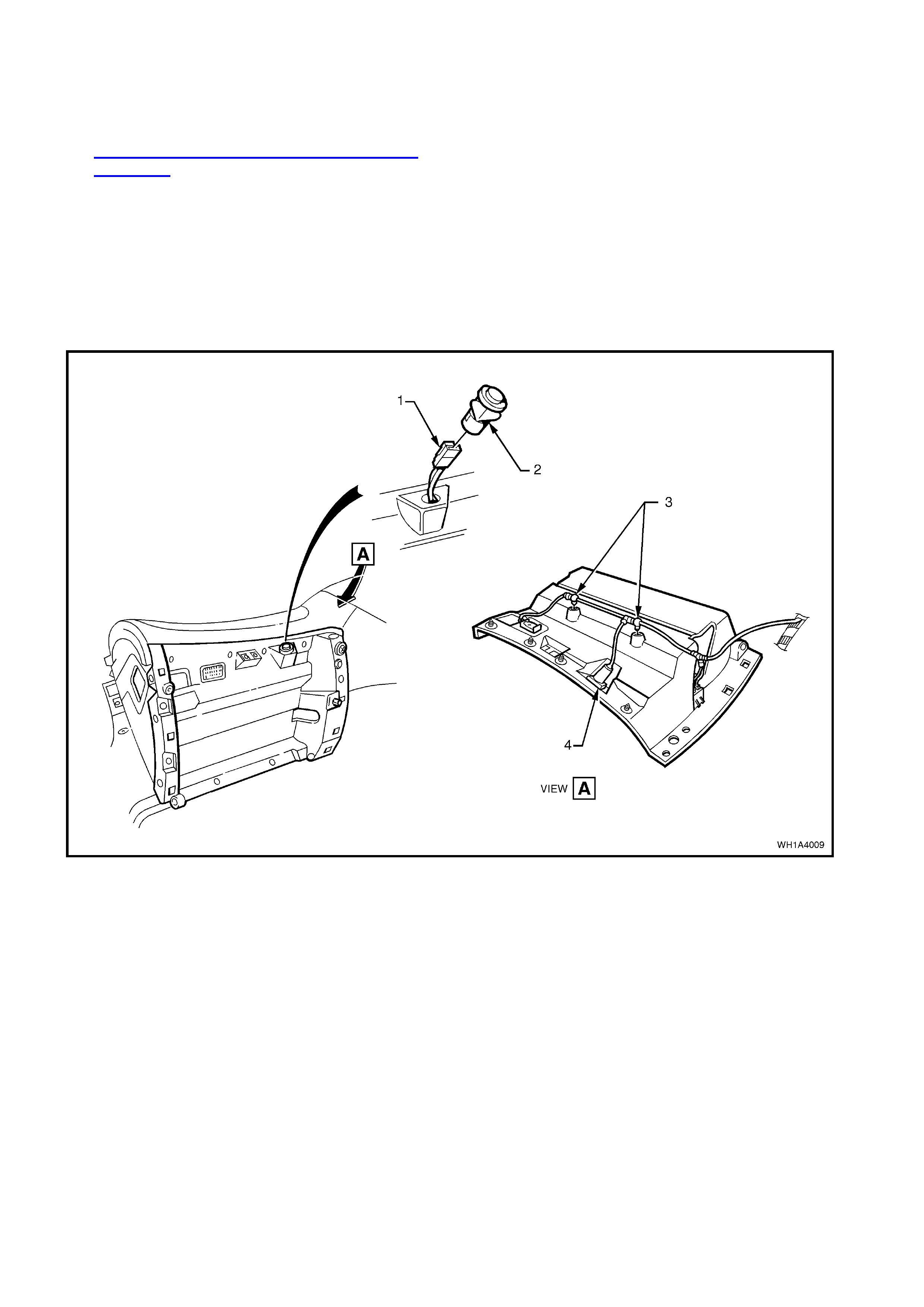
1.9 SWITCH ASSEMBLY - REAR COMPARTMENT LID LATCH ACTUATOR
REMOVE
1. Remove the instrument compartment, refer to
Section 1A3 INSTRUMENT PANEL AND
CONSOLE.
Disconnect the wiring harness connec tors from
the instrument panel compartment lamp, the
boot lid switch and instrument panel
compartment switch to facilitate removal of
instrument panel compartment. Unclip wiring
harness from instrument panel compartment.
2. Squeeze the locking tabs on the boot lid switch
and remove from instrument panel
compartment.
Figure 1A4-10
Legend
1. Rear compartment latch switch connector.
2. Rear compartment latch release switch. 3. Harness attached to glove box as shown.
4. Rear compartment lock release switch.
REINSTALL
Reverse removal operations.
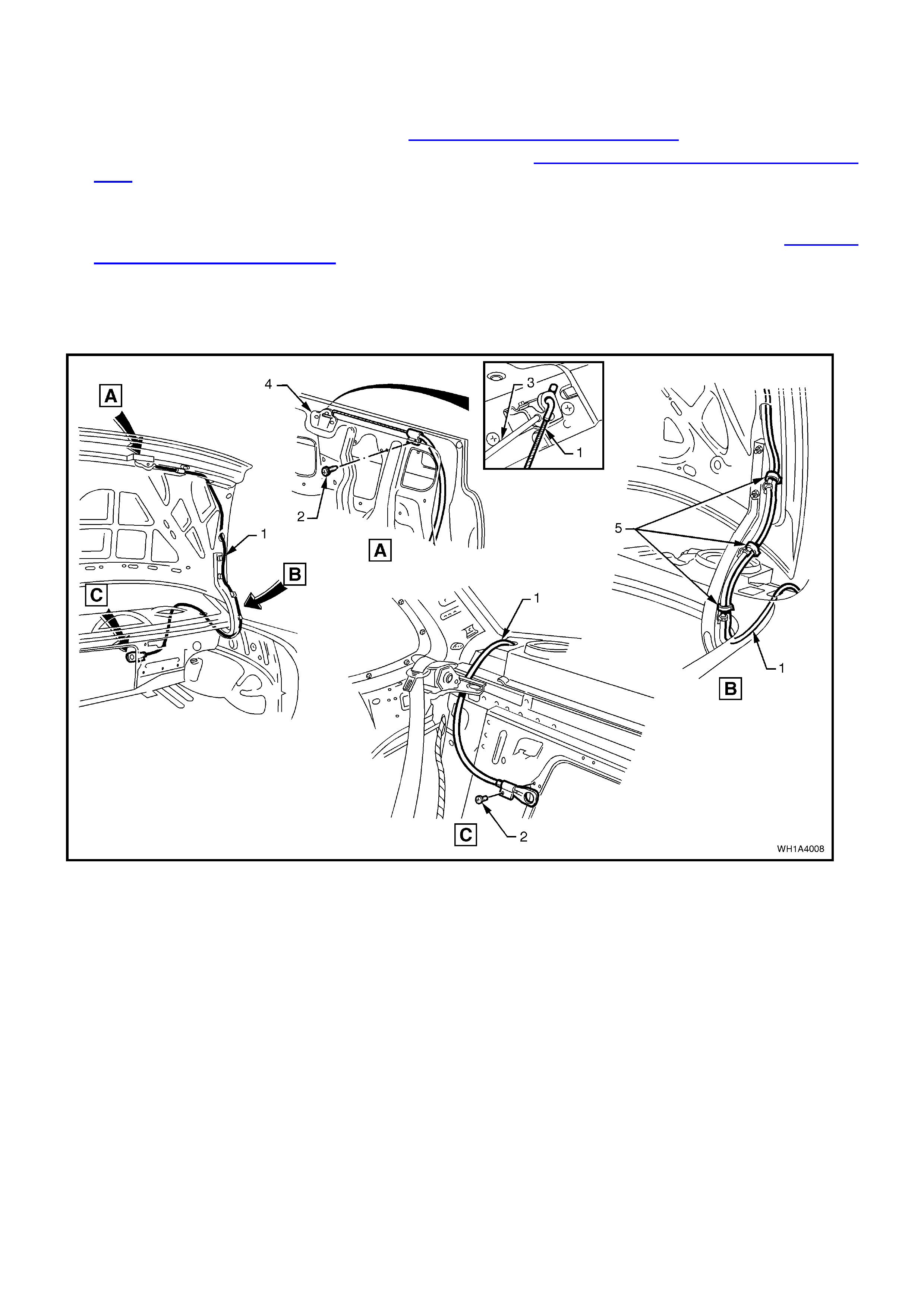
1.10 REAR COMPARTMENT LID REMOTE RELEASE CABLE ASSEMBLY
REMOVE
1. Remove the drivers side rear seat back, refer Section 1A7 SEAT AND SEAT BELTS.
2. Partially remove the drivers side rear parcel shelf trim, refer Section 1A8 HEADLINING AND REAR END
TRIM.
3. Remove the screw (2) securing the rear compartment lid remote release assembly to the rear seat back tray
opening.
4. From within the rear compartment remove the rear compartment lid carpet assembly refer 1.1 REAR
COMPARTMENT LID ASSEMBLY.
5. Remove the rear compartment lid latch assembly (4), disengage the cable from the latch assembly
6. Remove the screw (2) and the cable tie (5) securing the rear compartment lid rem ote release assembly to the
rear compartment lid.
7. Carefully feed the cable (1) into the passenger compartment removing the assembly.
Figure 1A4-11
Legend
1. Remote release cable assembly.
2. Screw.
3. Actuator rod.
4. Latch assembly.
5. Cable tie (4 places).
REINSTALL
Reverse removal operations.

2. TORQUE WRENCH SPECIFI CATIONS
Nm
Rear compartment lamp switch attaching screw.................. 1 - 3
Latch assembly securing screws.......................................... 2 - 5
Latch striker attaching screw................................................ 15 - 35
Actuator retaining screws...................................................... 2 - 5
Rear Compartment Lid Attaching Bolt.................................. 6-14