
SECTION 1A5 - FRONT & REAR
DOOR ASSEMBLIES
IMPORTANT
Before performing any Service Operation or other procedure described in this Section, refer to
Section 00 CAUTIONS AND NOTES for correct workshop practices with regard to safety and/or
property damage.
1. GENERAL DESCRI PTI O N
Front and rear door assemblies consist of outer panels which are hemmed at their outer edges, over the inner
panels. A rolled upper door frame retains the sliding glass run channels. Door hinge male sections are welded to
the door facings and the female sections to the body pillars. Door check and hold open links are located between
the door assemblies and the body pillars.
On front doors, double arm scissor type window regulators attached to the glass lifter channels and door inner
panels operate the front door sliding windows. Cable type m echanism s attached to the door inner panels and glass
lifter channels operate the rear door sliding windows.
Electric m otors for operating the f ront and rear sliding windows are s tandard equipment on States man and Caprice
models.
Lift bar exterior door handles operate the fork type door locks in conjunction with door lock striker bolts.
A two (2) key locking system uses a master key (with inbuilt remote security features) to operate all locks on the
vehicle. A secondary key, operates the glove compartment only. A snib locking button operates the door locks
internally.
The fr ont door lock cylinder is of the ‘fr ee turning’ design, pr eventing unlock ing of the door by objects other than the
correct key. If any object, except the correct key, is inserted into the lock, the cylinder will rotate without unlocking
the door.
Electric door lock actuators and electric external rear vision mirrors are standard features.
Door weatherstrips incorporate plastic clips which retain the weatherstrip in holes located around the outer lower
edge of the door inner panel. The upper section of the weatherstrip is retained in a channel which is an integral part
of the rolled section upper door frame.
Techline
Techline
Techline
2. SERVICE OPERATIONS
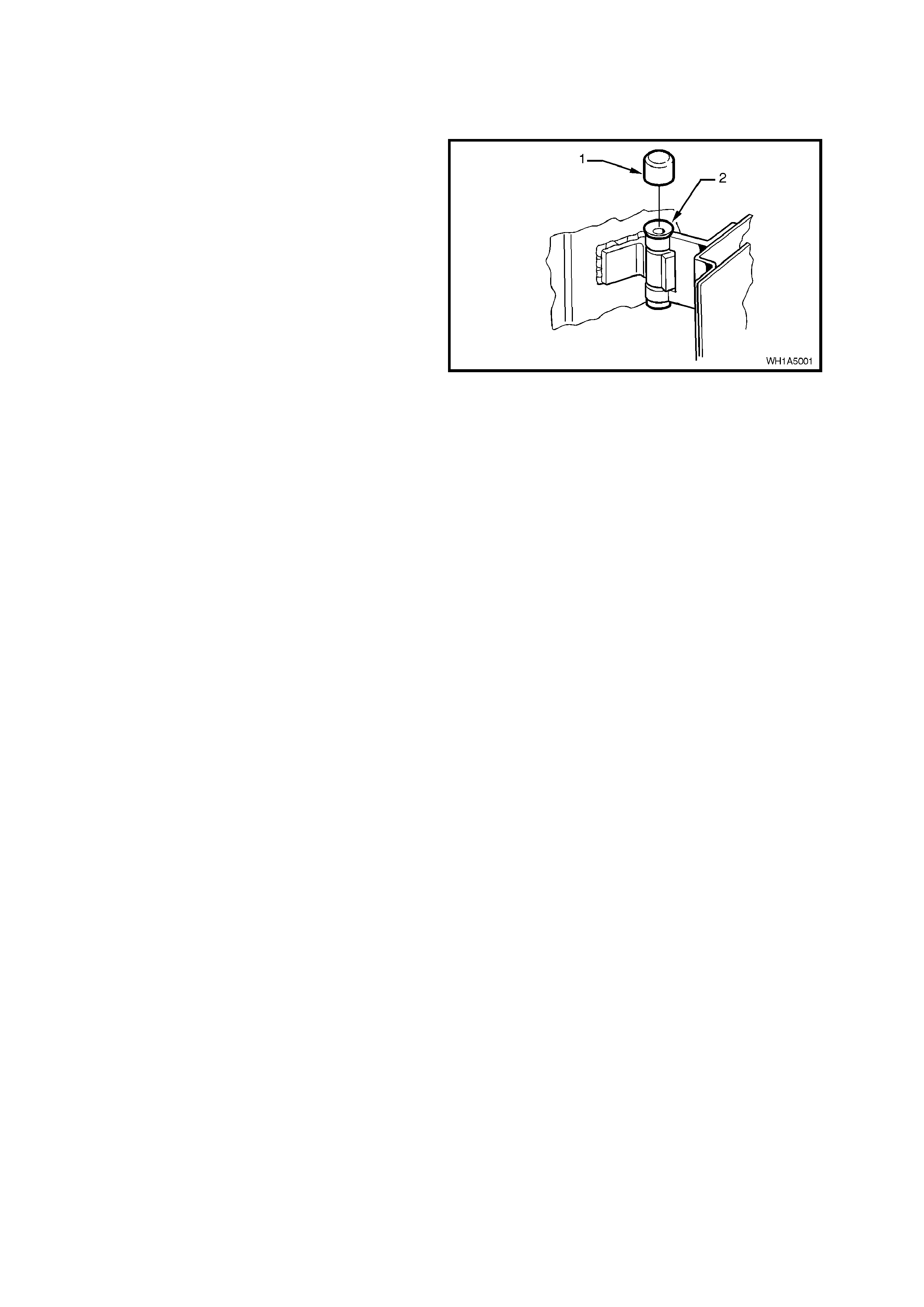
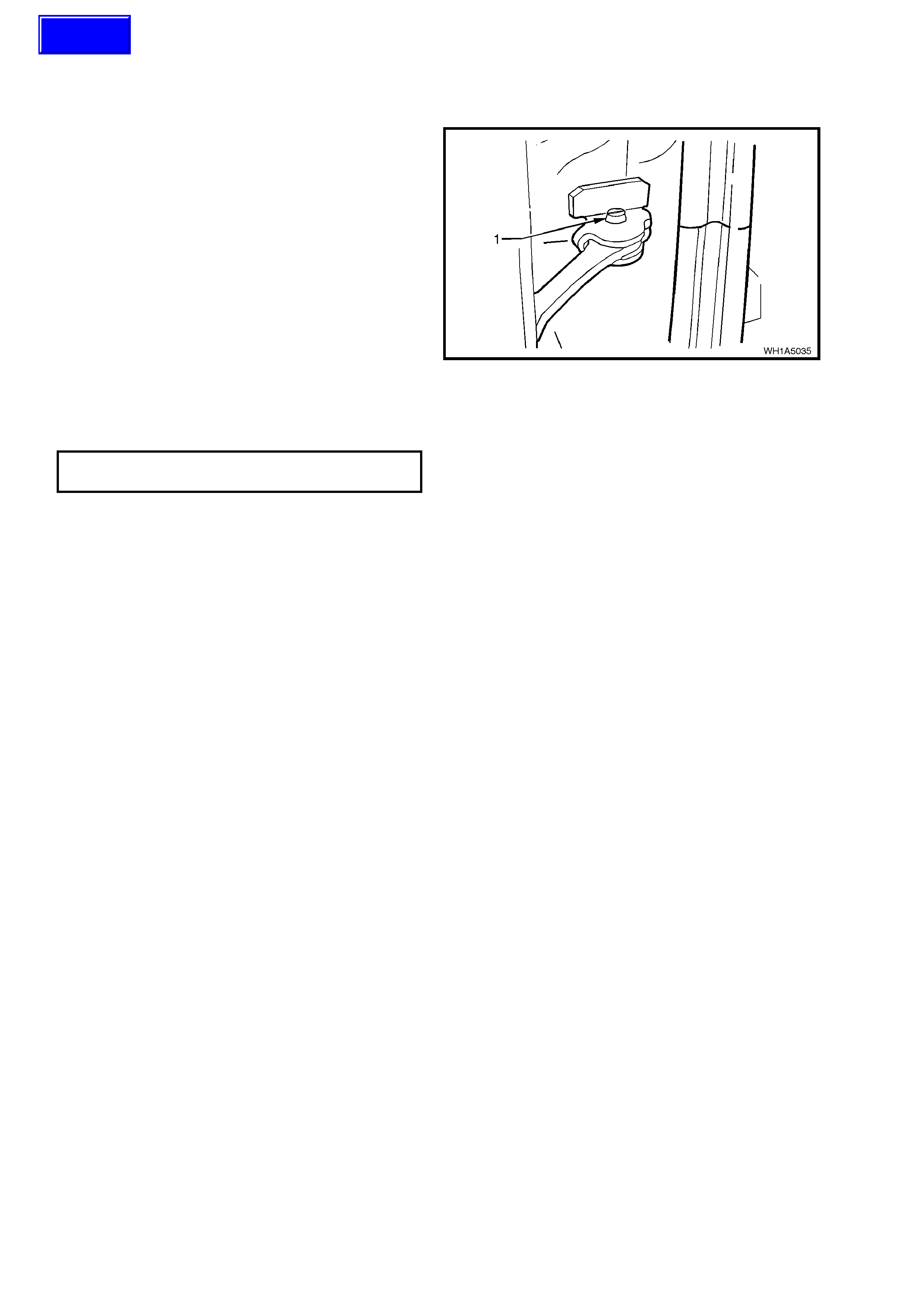
2.1 DOOR HINGE - LUBRICATION
1. Remove the lar ge plastic cap (1) f rom the door
hinge pivot sleeve (2).
2. Using a grease gun, inject into the hinge pivot
sleeve with a lithium base grease (NLGI No. 1
Lithium base grease to Holden Specification
HN 1225).
3. Reinstall large plastic cap over door hinge
sleeve.
Figure 1A5-1

2.2 FRONT AND REAR DOOR ASSEMBLIES
REMOVE
1. Disconnect the battery earth lead.
2. Remove grommet from door wiring harness
connector plug and insert Tool No. AU455 into
connector, depressing connector to door pillar
lock ing tangs (f ront door only) . By gently pulling
on wiring harness, remove door wiring harness
connector plug from pillar and disconnect.
Figure 1A5-2
3. On fr ont doors, tap the tapered s leeve secur ing
the link to the door check and hold-open
assembly upwards, removing the sleeve.
On rear doors, remove the bolt and nut
securing the link to the door check.
4. Using wooden blocks or car jacks, support the
door at its base.
5. Remove the plastic caps from the hinge (1)
assemblies.
6. Using Tool No. AU170, hinge sleeve removal
tool, drive out the upper and lower hinge.
Remove the door assembly. Figure 1A5-3
REINSTALL
Reinstallation of the door is the reverse of the
removal operation, noting the following:
1. Apply lithium base grease (NLGI No. 1 Lithium
base grease to Holden Specification HN 1225)
to the hinge pivot sleeves prior to installation.
2. Use Tool No. AU303, illustrated in Fig. 1A5-4,
to install the hinge pivot sleeves (1).
Figure 1A5-4

ADJUST
Attention should be given to uniform margins and
alignment between the door and surrounding parts
when door adjustments are being carried out.
Uniform margins and alignment of front and rear
doors in relation to the body opening can be
achieved by setting the appropriate door hinge.
Use Tool No. AU184 to set door hinges.
Adjust hinges in conjunction with adjustment to
lock striker to achieve an acceptable door closing
effort with correct door lock to striker engagement.
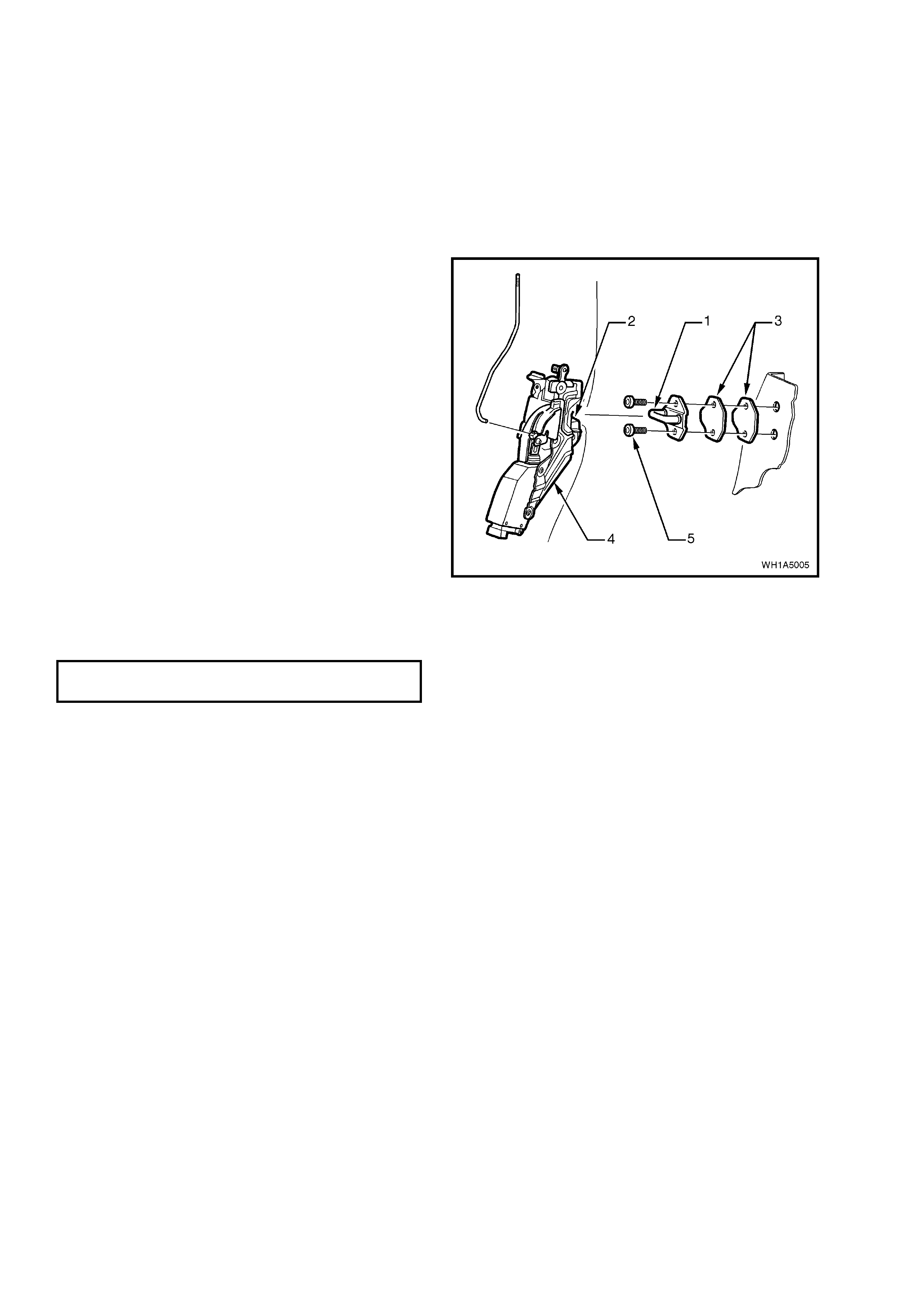
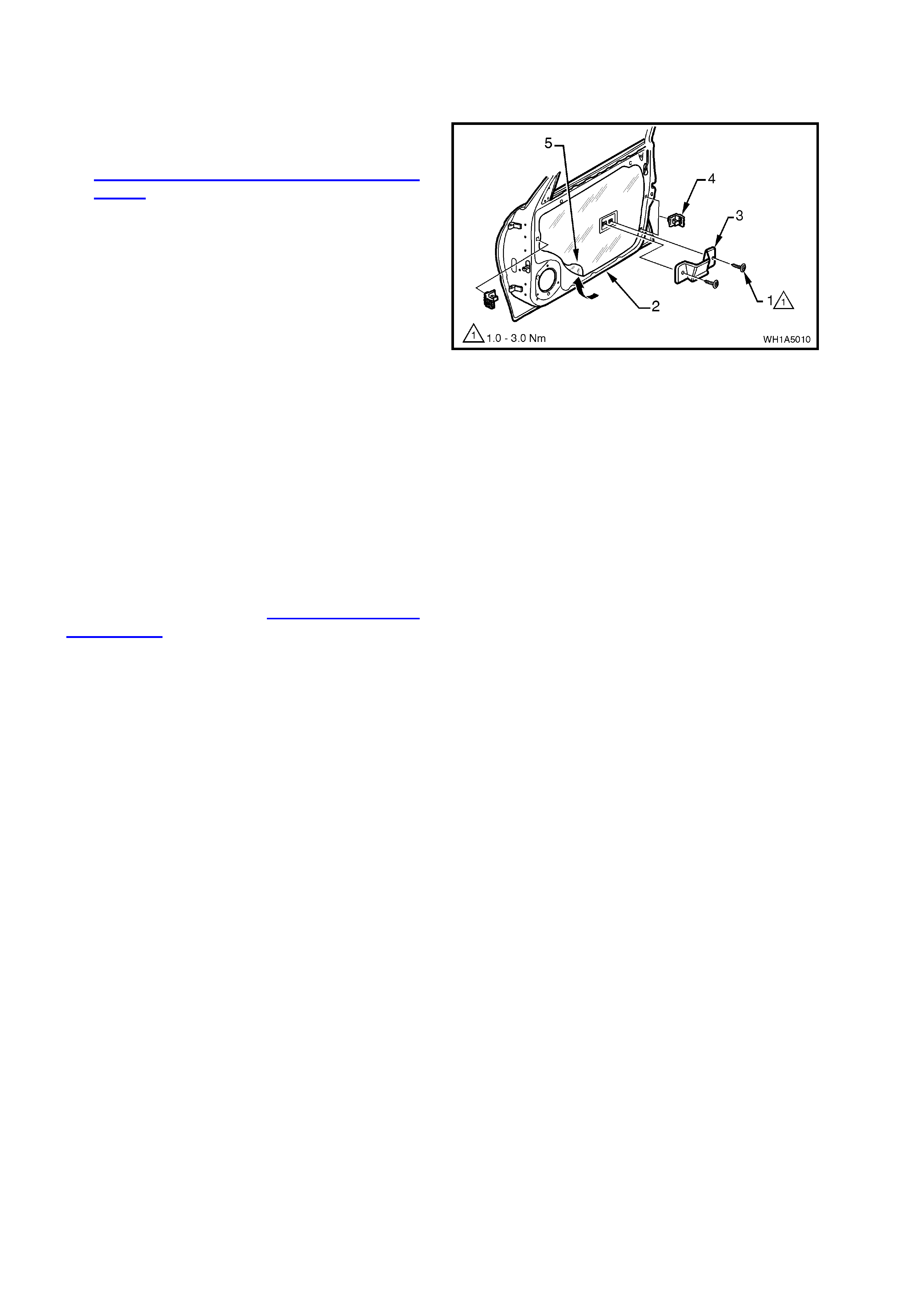
2.3 DOOR LOCK STRIKER ASSEMBLY
REMOVE OR ADJUST
1. Pencil scribe location of the striker assembly
on the body pillar to facilitate installation.
2. Using a Torx bit (30 T), loosen or remove the
striker assembly retaining bolts, remove striker
(if necessary).
REINSTALL
1. Align the striker assembly so that the bridge of
the striker (1) locates centrally in the lock
assembly (4) fork (2) (refer to Fig. 1A5-5) as
the door is being closed. Securely tighten the
striker assembl y.
2. Correct engagement can be achieved by
vertical or horizontal adjustment of the door
lock striker assembly. Add or delete spacers
(3) between the striker assembly and body
pillar to achieve correct engagement of the
striker to the lock.
NOTE: If a replacement door is being fitted, it is
sound practice to remove the door lock striker
assembly and allow the door to hang free on the
hinges. Set the hinges as necessary to achieve
correct alignment and uniform margins, then
reinstall the striker and adjust.
3. When correct alignm ent of the str iker assembly
is achieved, tighten striker assembly retaining
bolts (5) to the correct torque specification.
Figure 1A5-5
STRIKER ASSEMBLY RETAINING
BOLT TORQUE SPECIFICATION 8 - 18 Nm
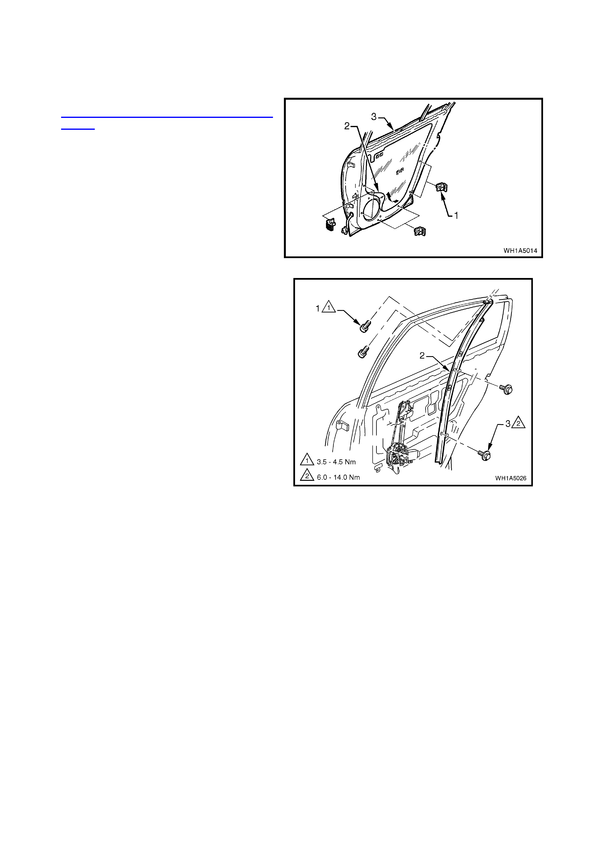
2.4 FRONT AND REAR DOOR INNER TRIM PANEL
NOTE:
When performing this service operation, the door
locking button retaining clamp will become
damaged and will need to be replaced. Therefore,
before carrying out this service operation, order a
door locking button retaining clamp from your
authorised Holden parts outlet.
REMOVE
1. Disconnect battery earth lead.
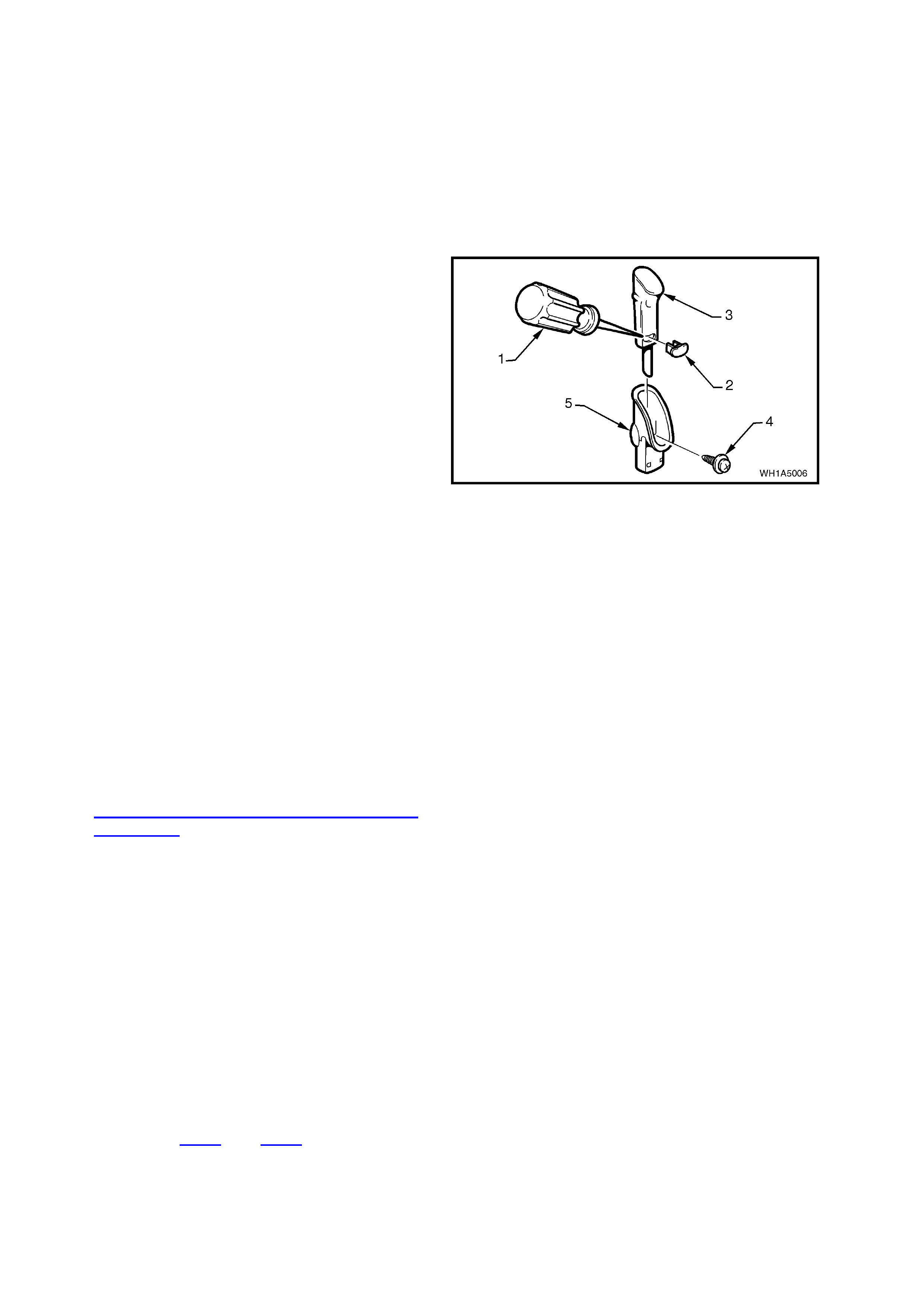
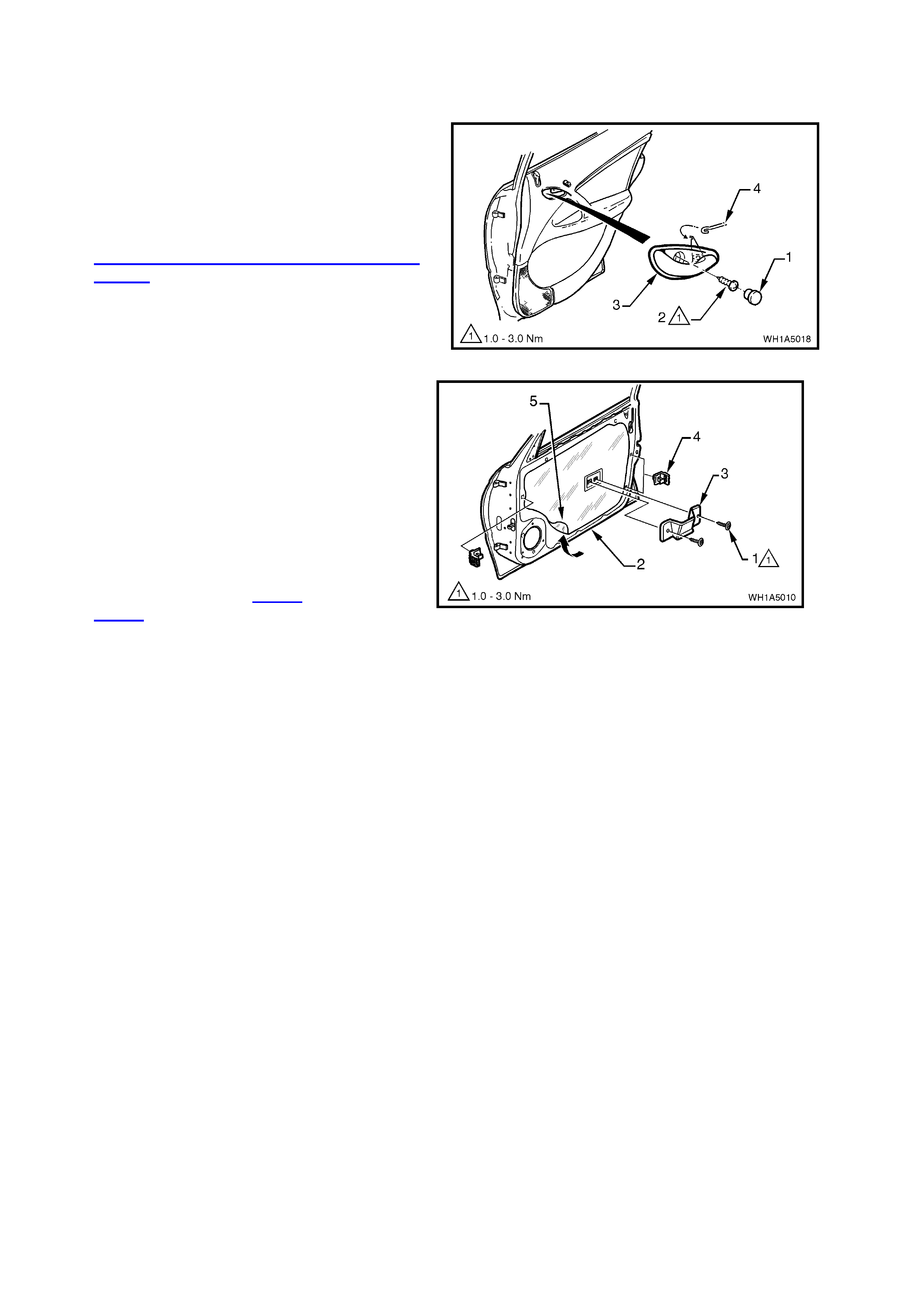
2. Using a sm all flat bladed scr ew dr iver or scribe
(1), gently pry the orange retaining clamp (2)
from the door locking button (3), taking care not
to damage the door locking button. Remove
the door locking button.
NOTE 1: The orange door locking button retaining
clamp will be damaged during this operation and
must be replaced.
Figure 1A5-6
3. Remove the screw (4) securing the door
lock ing button escutcheon (5) to the door inner
trim panel and remove the escutcheon.
NOTE 2: For the location of the components
described in the following steps, refer to Fig. 1A5-7.
4. Remove cap (6) covering screw and the screw
(7) securing the door remote control handle
assembly (8) to the door inner trim panel (5)
and remove the door remote control handle
assembly in a forward direction.
5. Remove the door inner trim panel retaining
screw (9) from the door remote handle
assembly aperture.
6. On front doors, remove the mirror inner cover
cap by gently prying cap away from door, refer
2.16 EXTERIOR REAR VISION MIRROR
ASSEMBLY.
7. Remove the door inner trim panel retaining
screws (21 and 10) from around the outside of
the door inner trim.
8. Lift the door inner trim panel up and out of door
inner channel, on f ront door s from the centre of
the door at the armrest, push the centre of the
door inner trim panel in to unclip the catch
behind the door inner trim while lifting refer to
Fig. 1A5-7, View A.
NOTE: Wiring harness connectors are still
connected.
9. While supporting door inner trim panel,
disconnect all wiring harness connectors.
10. Remove door inner trim panel.
NOTE: Figures 1A5-8 and 1A5-9 show the break
down of the front and rear door trim panel
assemblies.

REINSTALL
Reinstallation of the door inner trim panel is the
reverse of the removal operation, noting the
following:
1. Tighten all retaining screws to the correct
torque specification.
DOOR INNER TRIM PANEL
RETAINING SCREW
TORQUE SPECIFICATION 1 – 3 Nm
DOOR LOCKING BUTTON
ESCUTCHEON
RETAINING SCREW
TORQUE SPECIFICATION 1 – 3 Nm
DOOR REMOTE CONTROL
HANDLE ASSEMBLY
RETAINING SCREW
TORQUE SPECIFICATION
1 – 3 Nm
2. Ensure the door remote handle assembly and
remote control rod are engaged before final
fitment.
3. Use a new door locking button retaining clamp.
4. Replace inner mirror cover retaining clip.
NOTE: Screws along bottom of front door trim are
wax tip sealing screws.
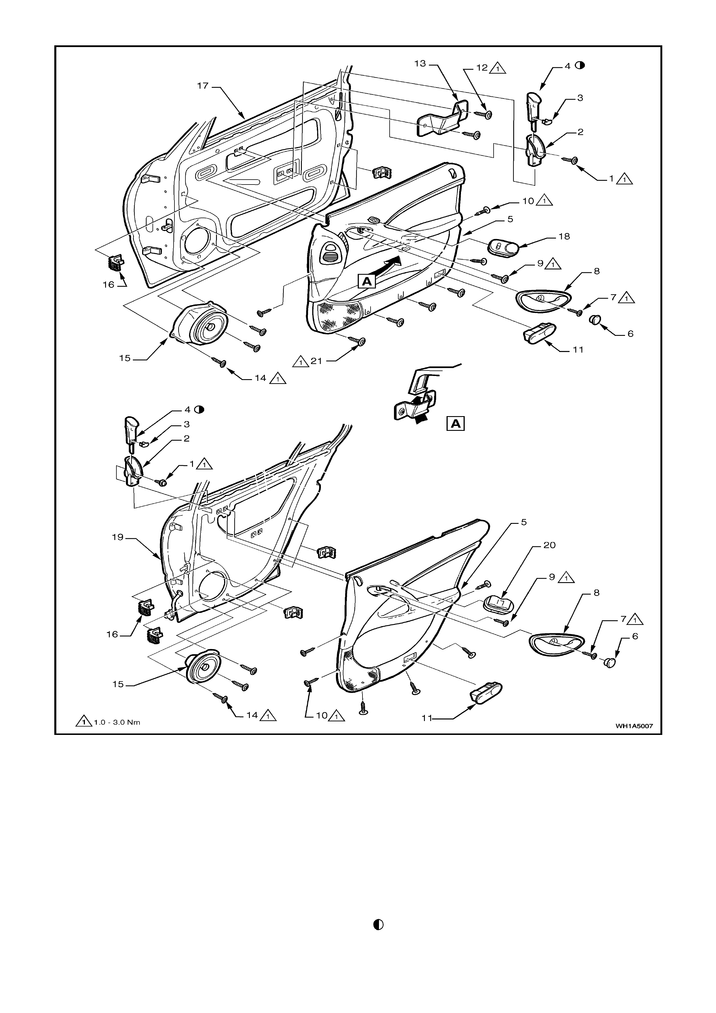
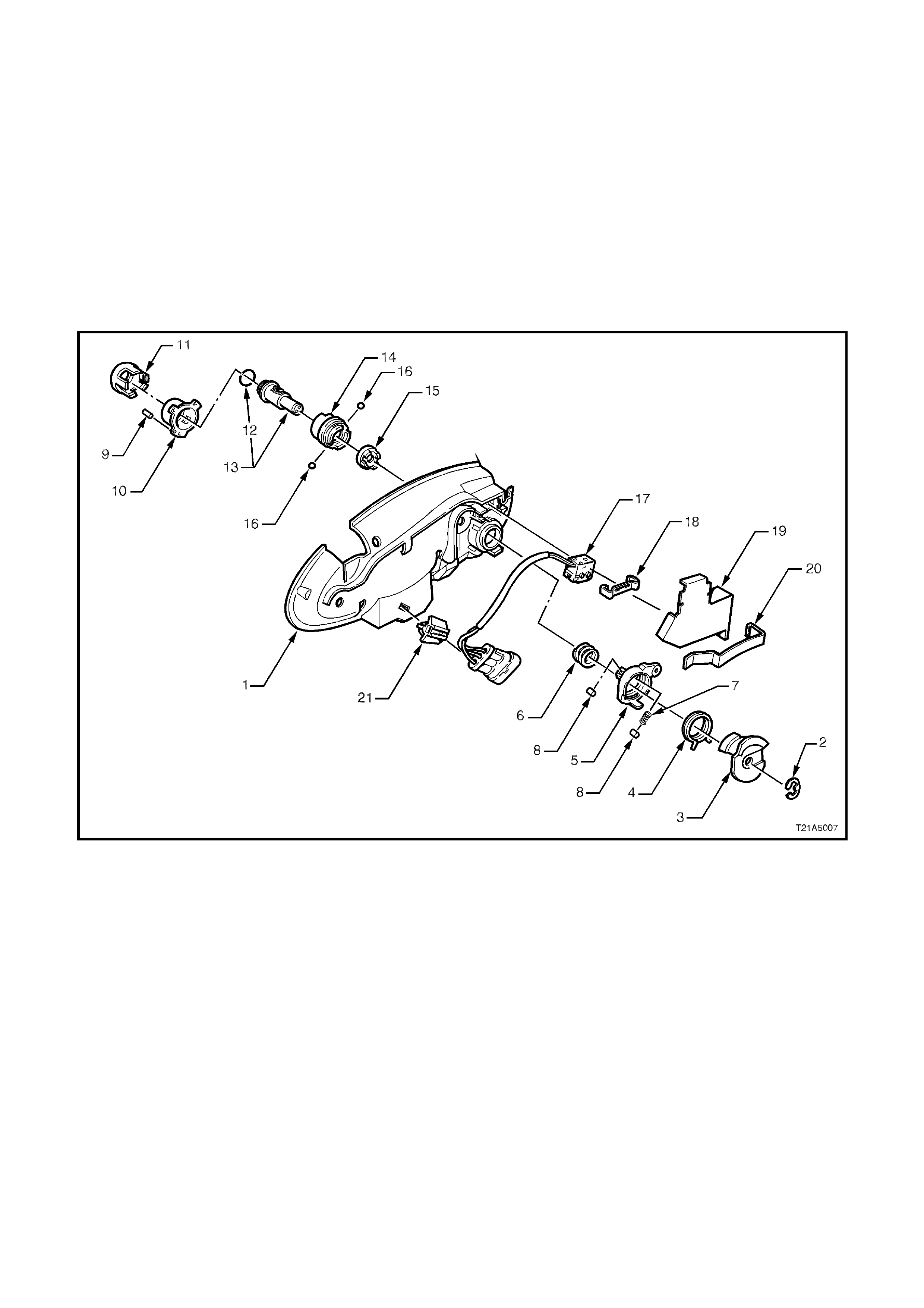
Figure 1A5-7
Legend
1. Screw.
2. Escutcheon.
3. Retaining clamp.
4. Button assembly.
5. Door inner trim panel.
6. Cap.
7. Screw.
8. Door remote control assembly.
9. Screw.
10. Screw (3 places front door 6 places rear door).
11. Courtesy lamp.
12. Screw (2 places).
13. Retaining bracket.
14. Screw (3 places).
15. Speaker and mounting box assembly.
16. Bracket (6 places).
17. Right hand front door assembly.
18. Mirror switch.
19. Right hand rear door
20. Power window switch.
21. Screw (4 places).
With lock in open position, slide button assembly
over rod as low down as possible and install clamp.

Figure 1A5-8
Legend
1. Screw (4 places).
2. Door pull handle.
3. Door demist duct.
4. Door vent duct.
5. Seal.
6. Front door trim substrate.
7. Clip (6 places).
8. Screw (7 places).
9. Screw.
10. Door speaker grille.
11. Door deposit box.
12. Front door applique.
13. Armrest insert.
14 Clip (5 places).
15. Clip (3 places).
16. Clip (5 places).
17. Air outlet housing.
18. Weatherstrip.
19. Insulator.
20. Screw (3 places) .
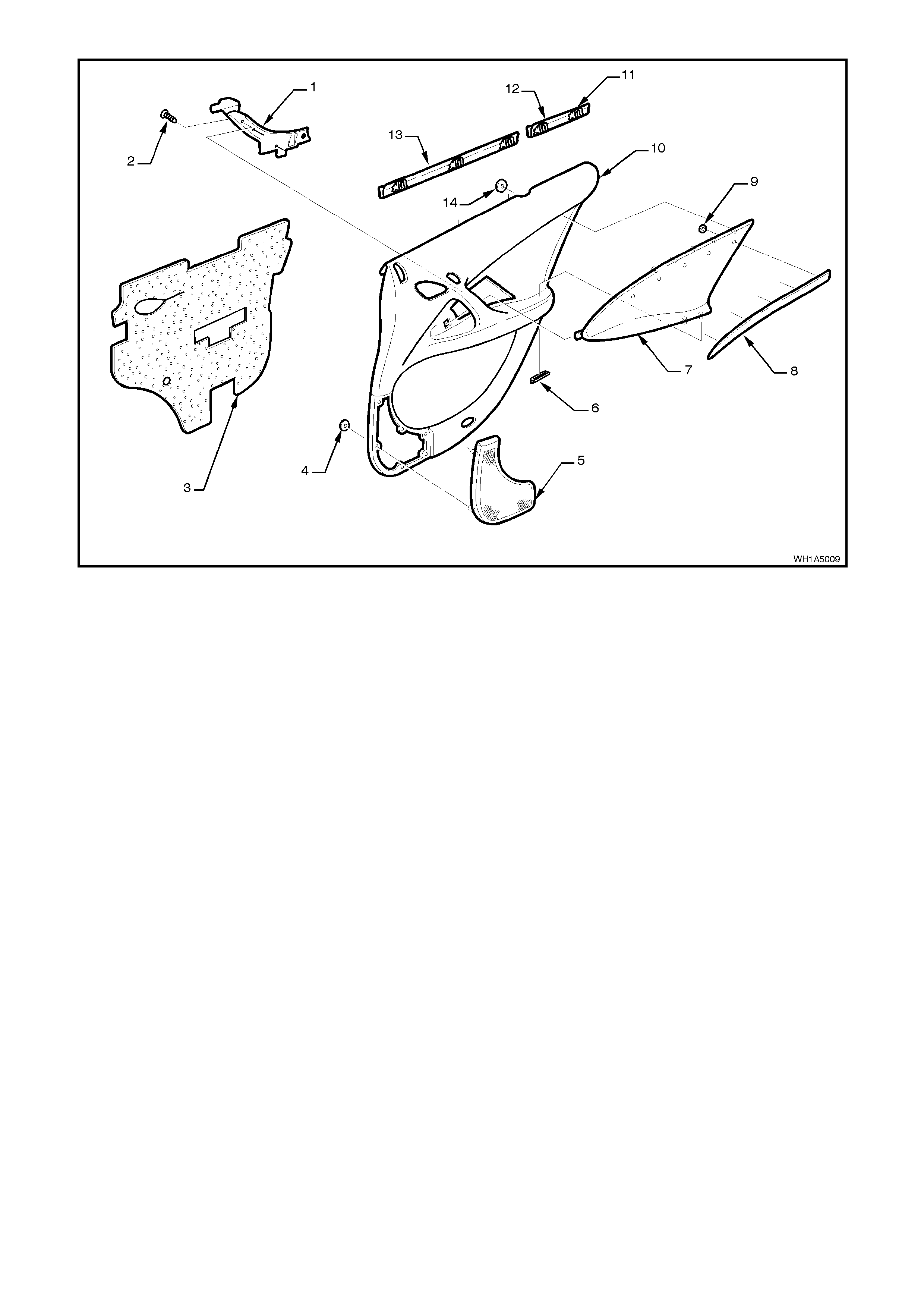
Figure 1A5-9
Legend
1. Door pull handle.
2. Screw (4 places).
3. Door trim insulator.
4. Clip (7 places).
5. Door speaker grille.
6. Clip (2 places).
7. Armrest insert.
8. Rear door applique.
9. Clip (5 places).
10. Rear door trim substrate.
11. Clip (5 places).
12. Weatherstrip rear.
13. Weatherstrip front.
14. Clip (5 places).
2.5 FRONT DOOR LOCK AND ACTUATOR ASSEMBLY
REMOVE
1. Disconnect battery ground cable.
2. Remove the door inner trim panel refer to
2.4 FRONT AND REAR DOOR INNER TRIM
PANEL in this Section.
3. Remove the two screws (1) securing the inner
trim panel retaining bracket to the door and
remove retaining bracket (3). Remove inner
trim retaining brackets (4) by levering out the
centre pin of bracket.
4. Carefully peel off the water deflector (5) from
the door inner panel (2).
5. Referring to Fig. 1A-4, disconnect the actuator
to door harness electrical connector then
remove screws (2) securing the door lock and
actuator assembly to door inner panel.
6. Disconnect actuator control rods from the
retainers then remove the assembly through
the aperture in the door inner panel.
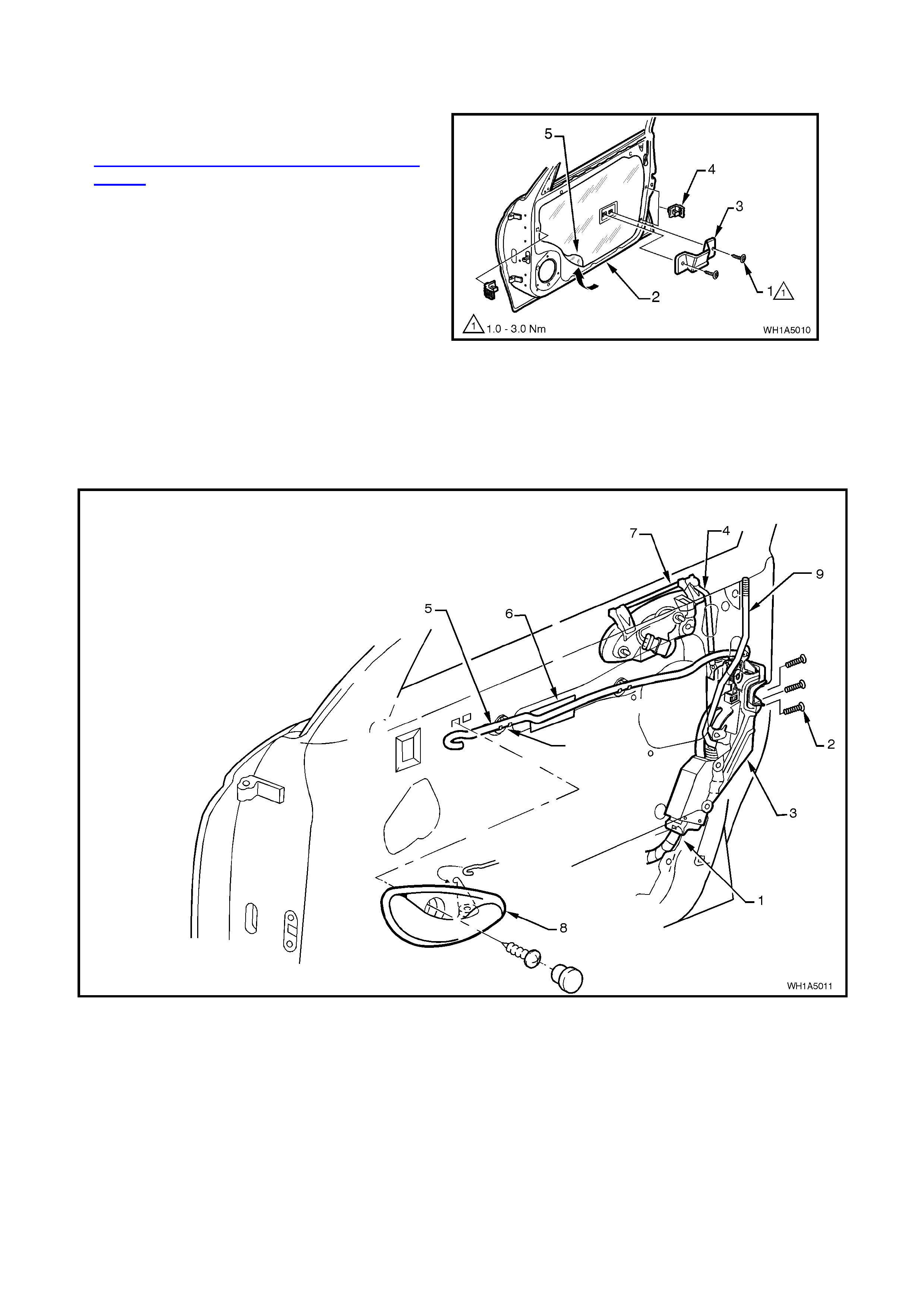
Figure 1A5-10
Figure 1A5-11
Legend
1. Actuator to door harness electrical connector.
2. Screw (3 places).
3. Front door lock and actuator assembly.
4. Exterior door handle to actuator rod.
5. Remote control rod.
6. Foam.
7. Exterior door handle assembly.
8. Door remote control handle assembly.
9. Door locking rod.
ADJUST
Adjustment of each door lock and actuator is
critical to ensure correct operation of the electric
door lock system.
The following adjustment procedure is to be
performed if a diagnostic test in Section 12J-2
HIGH SERIES BCM suggests that the door lock
and actuator assembly may be incorrectly adjusted,
or if any of the following symptoms occur:
• Ineffective deadlock operation.
• Failure to lock and unlock.
• Door lock actuator motors oscillate, ie.
machine gunning.
1. If not already done so, remove door lock and
actuator assembly.
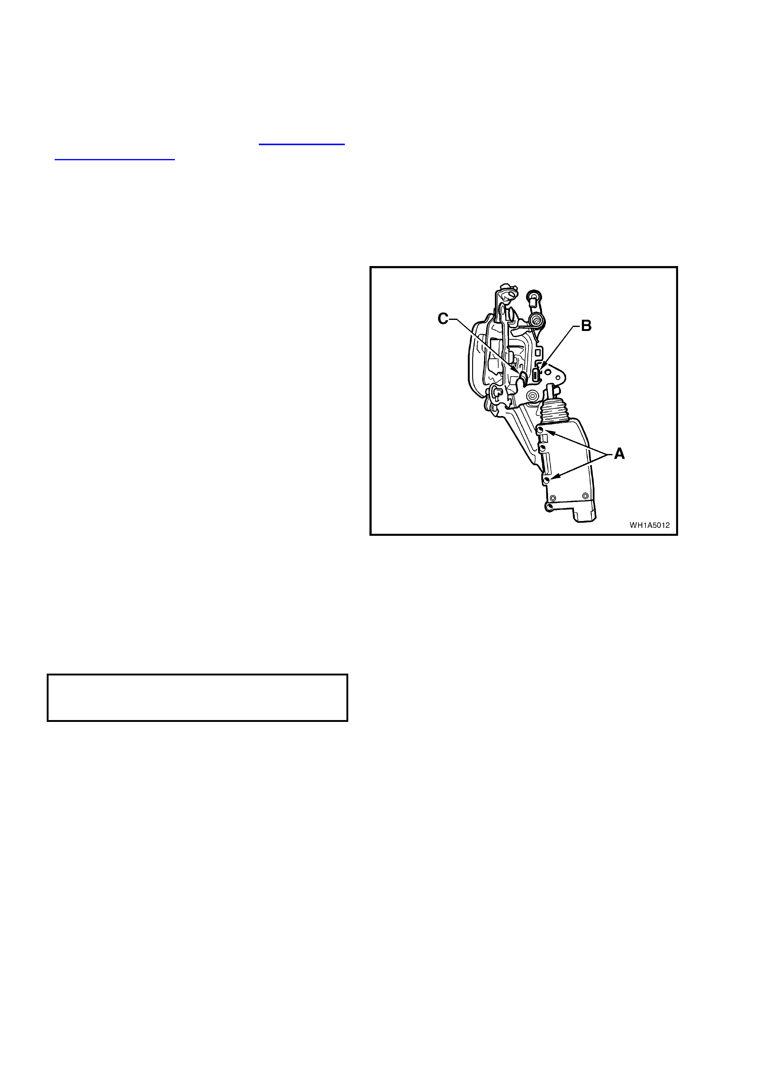
2. Using the door locking button rod lever, LOCK
and UNLOCK the actuator mechanism,
checking that the actuator lever ‘B’ rests on
rubber pad ‘C’, refer to Fig. 1A5-12.
3. If requir ed, loosen s c r ews ‘A’ and repos ition the
actuator motor until the required position is
achieved.
4. Tighten actuator to motor screws securely
without moving the motor position.
Figure 1A5-12
REINSTALL
Reinstallation of the front door lock and actuator
assembly is the reverse of the removal operation,
noting the following:
1. Tighten all retaining screws to the correct
torque specification.
DOOR LOCK AND ACTUATOR
ASSEMBLY RETAINING SCREW
TORQUE SPECIFICATION 3 – 5 Nm
2. Ensure that water deflector is sealed correctly
against door panel.
3. Use a new door locking button retaining clamp.
2.6 REAR DOOR LOCK AND ACTUATOR ASSEMBLY
REMOVE
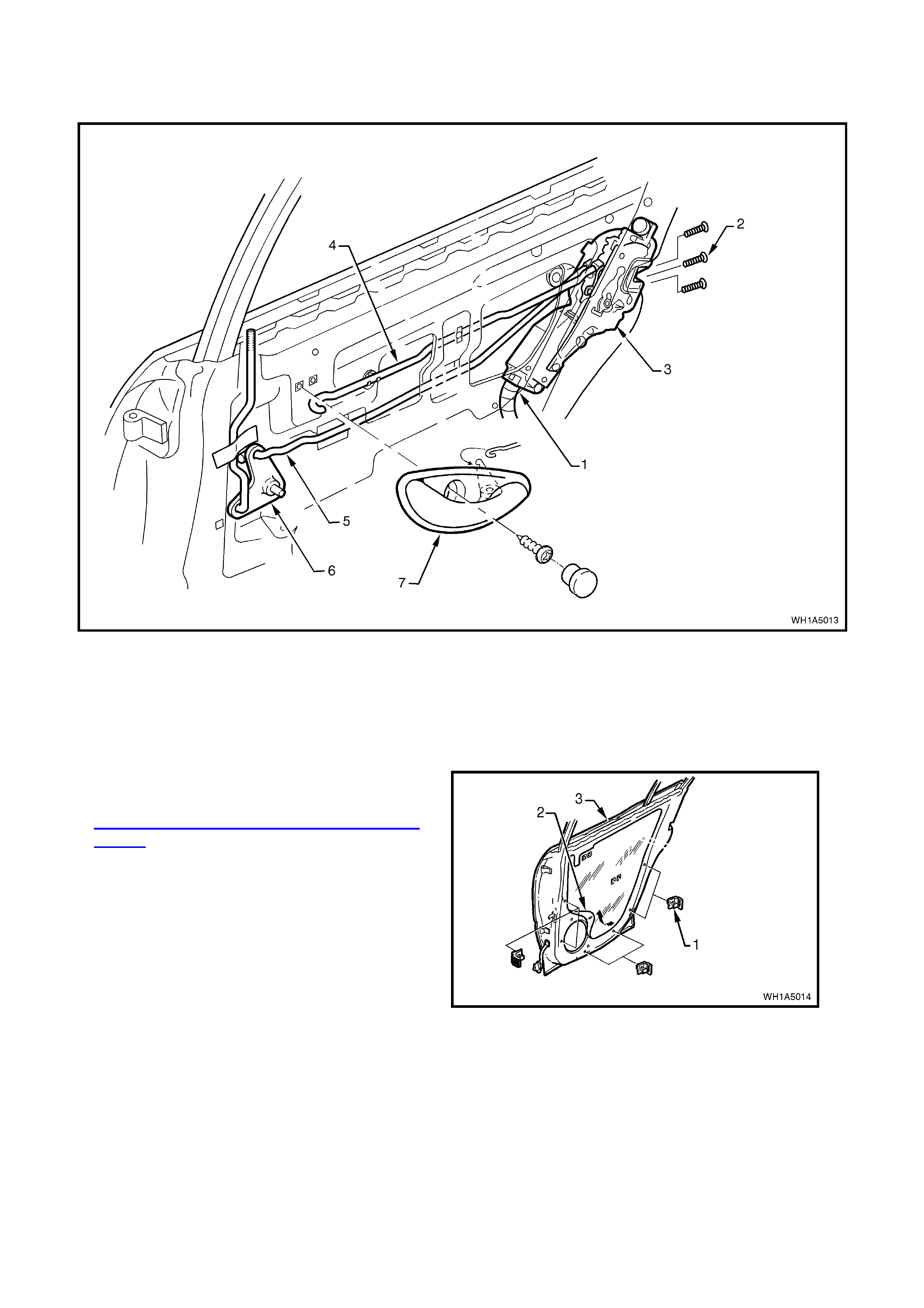
Figure 1A5-13
Legend
1. Actuator to door harness electrical connector.
2. Screw (3 places).
3. Rear door lock and actuator assembly.
4. Remote control rod.
5. Door locking rod.
6. Crank assembly.
7. Door remote control handle assembly.
1. Disconnect battery earth lead.
2. Remove the door inner trim panel, refer to
2.4 FRONT AND REAR DOOR INNER TRIM
PANEL.
3. Carefully peel off the water deflector (2) from
the door inner panel (3).
4. Referring to Fig. 1A5-13, disconnect the
actuator to door harness electrical connector
then remove screws (2) securing the door lock
and actuator assembly to door inner panel.
5. Disconnect actuator control rods from the
retainers then remove the assembly through
the aperture in the door inner panel. Figure 1A5-14

ADJUST
Adjustment of each door lock and actuator
assembly is critical to ensure correct operation of
the electric door lock system.
The following adjustment procedure is to be
performed if a diagnostic test in Section 12J-2
HIGH SERIES BCM suggests that the door lock
and actuator may be incorrectly adjusted, or if any
of the following symptoms occur:
• Ineffective deadlock operation.
• Failure to lock and unlock.
• Door lock actuator motors oscillate, ie.
machine gunning.
1. If not already done so, remove door lock and
actuator assembly.
2. Using the door locking button rod lever, LOCK
and UNLOCK the actuator mechanism,
checking that the actuator bump stop ‘B’ rests
on actuator lever ‘C’, refer to Fig. 1A5-15.
3. If requir ed, loosen s c r ews ‘A’ and repos ition the
actuator motor until the required position is
achieved.
4. Tighten actuator to motor screws without
moving the motor position.
REINSTALL
Reinstallation of the front door lock and actuator
assembly is the reverse of the removal operation,
noting the following:
1. Tighten all retaining screws to the correct
torque specification. Figure 1A5-15
DOOR LOCK AND ACTUATOR
ASSEMBLY RETAINING SCREW
TORQUE SPECIFICATION 3 - 5 Nm
2. Ensure that the water deflector is sealed
correctly against the door inner panel.
3. Use a new door locking button retaining clamp.
2.7 FRONT DOOR EXTERIOR HANDLE AND LOCK CYLINDER ASSEMBLY
REMOVE
1. Disconnect battery earth lead.
2. Remove the door inner trim panel refer to
2.4 FRONT AND REAR DOOR INNER TRIM
PANEL.
3. Remove the two screws (1) securing the inner
trim panel retaining brack et (3) to the door and
remove retaining bracket. Remove inner trim
retaining brack ets (4) by levering out the centre
pin of bracket.
4. Carefully peel off the water deflector (5) from
the door inner panel (2).
5. Driver’s door only; disconnect the door lock
cylinder control rod (1) from the door lock and
actuator assembly (2) by releasing the rod
retainer clip, refer to Fig. 1A5-17.
6. Driver’s door only; disconnect door wiring
harness from door lock micro-switch wiring
harness connector (3) at exterior door handle.
7. Remove the two exterior door handle retaining
nuts (5), and remove exterior door handle (6).
NOTE 1: The exterior door handle bracket on the
driver’s door is an assembly and consists of a
mic ro- s witch, door loc k cylinder and bracket. These
parts are serviced and sold as an assembly only.
NOTE 2: To test the door micro-switch, depending
on model variant, refer to Section 12J-2 HIGH
SERIES BCM.
NOTE 3: Fig. 1A5-17 shows the driver’s door
exterior handle with micro-switch and wiring
harness.
Figure 1A5-16
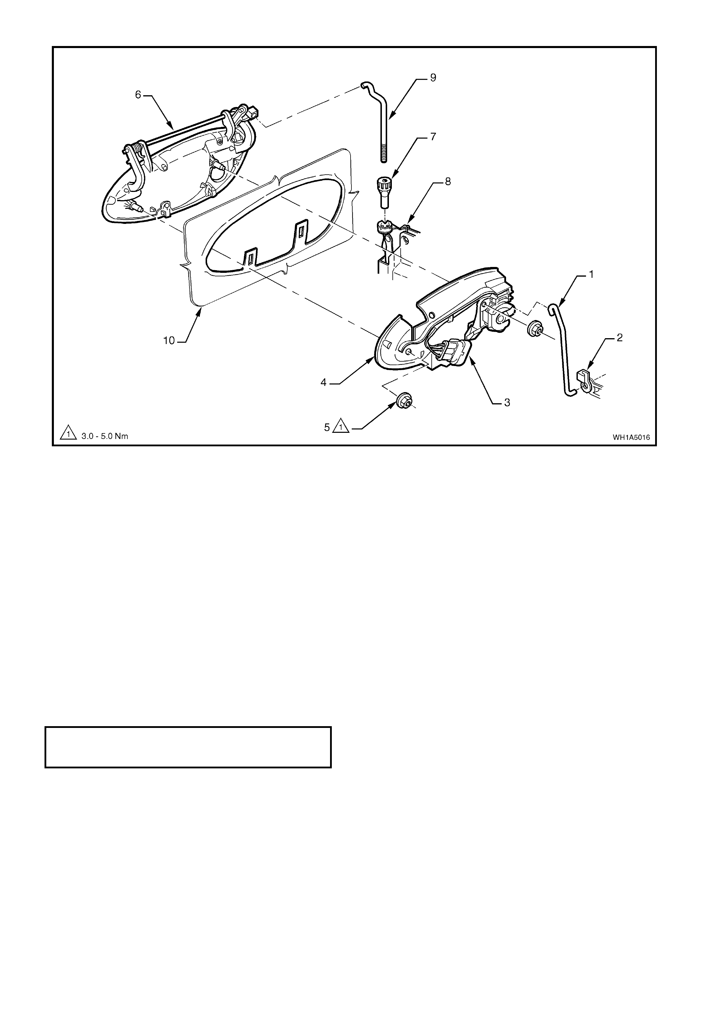
Figure 1A5-17
Legend
1. Door lock cylinder control rod.
2. Lock and actuator assembly.
3. Microswitch harness connector (Drivers door only).
4. Exterior door handle bracket assembly.
5. Retaining nut.
6. Exterior door handle.
7. Adjusting nut.
8. Lock and actuator assembly.
9. Exterior door handle rod.
10. Door outer panel.
REINSTALL
Reinstallation of the front door exterior handle
assembly is the reverse of the removal operation,
noting the following:
1. Ensure that the adjusting nut (7) is seated in
the lock and actuator assembly (8) before
installing the exterior door handle assembly
retaining nuts (5).
2. Tighten retaining nuts to the correct torque
specification.
EXTERIOR DOOR HANDLE
ASSEMBLY RETAINING NUT
TORQUE SPECIFICATION 3 - 5 Nm
3. Check and if necessary, adjust the exterior
door handle adjusting nut to allow latch
disengagement with striker when the exterior
door handle opening is 18° ± 5° from the rest
position.
4. Ensure the water deflector is sealed correctly
to door and use a new door locking button
retaining clamp.
RESET (‘FREE TURN’ LOCK CYLINDER)
NOTE: If the ‘free turn’ lock cylinder becomes
mis aligned due to the insertion of the incor rect k ey,
a foreign object or if the correct k ey is not inserted
fully when turned, the following procedure will need
to be carried out.
1. Insert the key fully into the lock, preferably in
the vertical position and turn the key slowly
anti-clockwise - until a click is felt.
2. Then slowly turn k ey clock wise - until a click is
felt.
3. Return the key to the vertical position (if not
already there) and withdraw the key.
4. Reinsert the key at the vertical position and
check if the key will lock and unlock the
vehicle.
NOTE: If the key does not wor k properly, keep key
in lock and turn key 180° anti-clockwise, then
repeat the procedure.
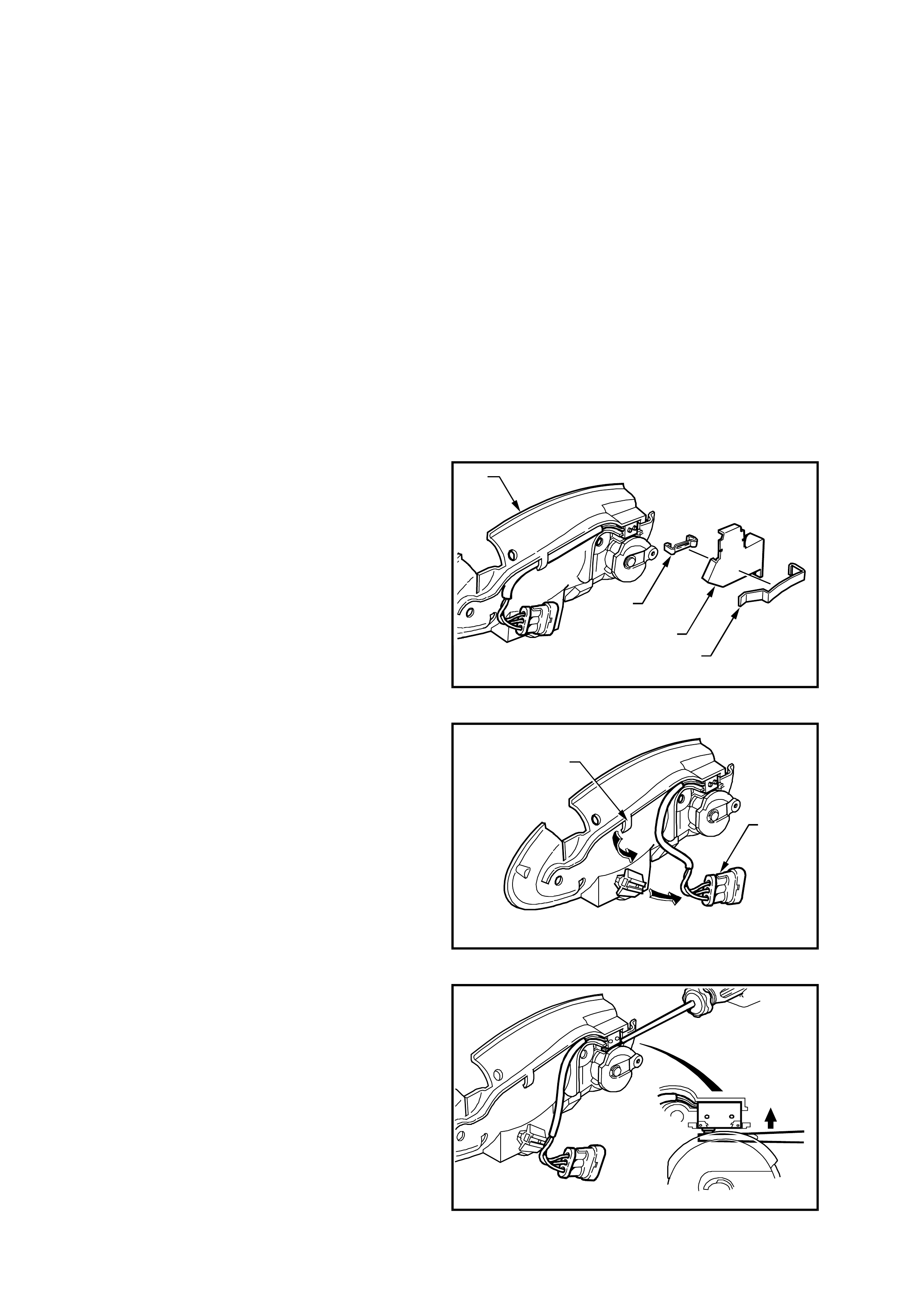
DISASSEMBLY
1. Using a small screwdriver, gently prise the
retaining clip (20) away from the door handle
bracket assembly (1) and remove the security
shield (19).
2. Using a small screwdriver, gently prise the
microswitch retaining clip (18) away from the
door handle bracket assembly (1).
T21A5001
1
19 20
18
Figure 1A5-18
3. Slide the microswitch wiring harness connector
(22) off the connector retaining bracket and
feed the wiring harness out from under the
bracket assembly retainer (23).
T21A5002
23
22
Figure 1A5-19
4. Using a small flat bladed screwdriver, push the
two microswitch contacts in and remove the
microswitch assembly.
T21A5003
Figure 1A5-20
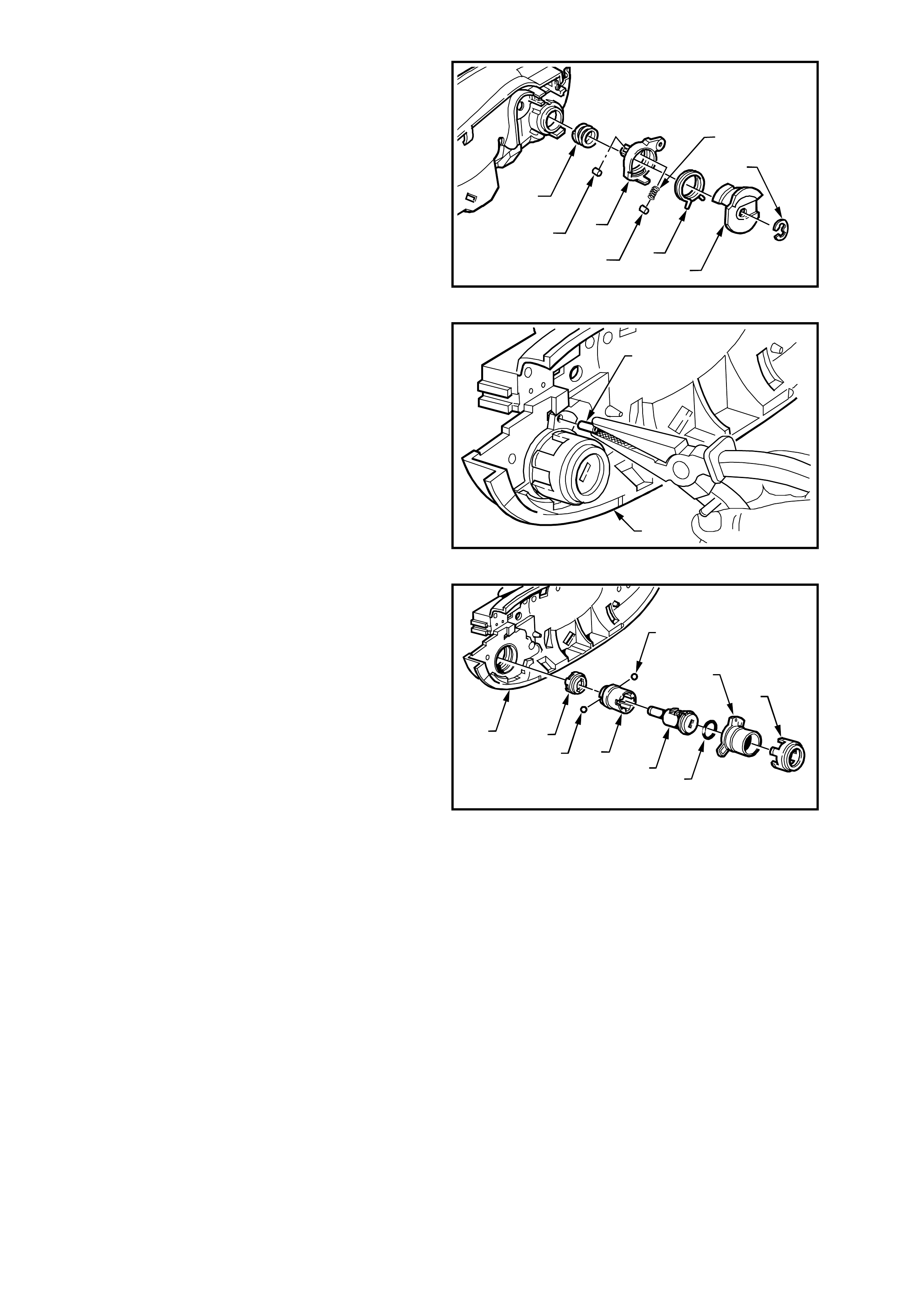
5. Remove the circlip (2) and slide the cam
control, clips and springs (3, 4, 5, 6, 7 & 8)
away from lock assembly.
T21A5004
6
8
83
2
7
5
4
Figure 1A5-21
6. Using a suitable pier of pliers, pull the roll pin
(9) out of the door handle bracket assembly.
T21A5005
9
1
Figure 1A5-22
7. Rotate lock housing anti-clock wise and rem ove
decorative housing, lock housing, O-ring, lock
assem bly, lock assem b ly sleeve, retaining balls
(two places) and coupling (10, 11, 12, 13, 14,
15 & 16) from the door handle bracket
assembly (1).
T21A5006
16
16 14
1
13 12
11
10
15
Figure 1A5-23
REASSEMBLY
Reassembly of the front door exterior handle and
lock assembly is the reverse of the removal
procedure, noting the following:
1. The Holden Service Parts Operations
departm ent supplies service k its with un-coded
lock cylinders to facilitate re-coding of the lock
cylinder to match the original key.
Holden Ltd. recommends lock cylinder
overhaul and re-coding be performed by a
qualified locksmith, and should be sublet.
2. To assist assembly of the front door exterior
handle and lock assembly, the following figure
shows an exploded view of the assembly.
Figure 1A5-24
Legend
1. Exterior Door Handle Bracket 8. Roller 15. Coupling
2. Circlip 9. Roll Pin 16. Retaining Balls
3. Cam Control 10. Lock Housing 17. Microswitch Assembly
4. Spring 11. Decorative Housing 18. Retaining Clip
5. Clip 12. O-Ring 19. Security Shield
6. Push Spring 13. Cylinder Lock Assembly 20. Retaining Clip
7. Push Spring 14. Cylinder Lock Sleeve 21. Connector Retaining Bracket

2.8 REAR DOOR EXTERIOR HANDLE ASSEMBLY
REMOVE
1. Remove the door inner trim panel refer
2.4 FRONT AND REAR DOOR INNER TRIM
PANEL in this Section.
2. Carefully peel off the water deflector (2) from
the door inner panel (3).
Figure 1A5-25
3. Remove the two exterior door handle retaining
nuts (1), and remove exterior door handle (2).
Figure 1A5-26
REINSTALL
Reinstallation of the rear door exterior handle
assembly is the reverse of the removal operation,
noting the following:
1. Referring to Fig. 1A5-26 ensure that the
adjuster nut (3) is seated in the lock assembly
(4) before installing the exterior door handle
assembly retaining nuts (1).
2. Tighten door handle retaining nuts to the
correct torque specification.
EXTERIOR DOOR HANDLE
ASSEMBLY RETAINING NUT
TORQUE SPECIFICATION 3 - 5 Nm
3. Check and if necessary, adjust the exterior
door handle adjustment nut to allow latch
disengagement with striker when the exterior
door handle opening is 18° ± 5° from the rest
position.
4. Ensure the water deflector is sealed correctly
to the door panel.
5. Use a new door locking button retaining clamp.
2.9 REMOTE CONTROL HANDLE AND ROD ASSEMBLY
REMOVE
1. Remove the screw cap (1) and screw (2)
securing the door remote control handle
assembly (3) to the door inner panel and
remove the door remote control handle
assembly in a forward direction unhooking the
remote rod from the handle assembly .
2. Remove the door inner trim panel refer to
2.4 FRONT AND REAR DOOR INNER TRIM
PANEL.
Figure 1A5-27
3. On front doors remove the two screws (1)
securing the inner trim panel retaining bracket
(3) to the door and remove retaining bracket.
Remove inner trim retaining brackets (4) by
levering out the centre pin of bracket.
4. Carefully peel off the water deflector (5) from
the door inner panel.
5. Unclip the remote control handle rod from the
door inner panel (2 places) and disengage the
remote control handle rod from the door lock
and actuator assembly by releasing the r etainer
clip, refer (5) in Fig.1A5-12 .or (4) in Fig.
1A5-13.Figure 1A5-28
REINSTALL
Reinstallation of the remote control handle and rod
assembly is the reverse of the removal operation,
noting the following:
1. Ensure the door remote handle assembly and
remote control rod are engaged before final
fitment, refer to Fig. 1A5-27 above.
2. Ensure the water deflector is sealed correctly
against the door panel.
3. Use a new door locking button retaining clamp.
2.10 FRONT DOOR WINDOW AND REGULATOR ASSEMBLY
NOTE: To remove, test and the power window
switch, depending on model variant, refer to
Section 12J-2 HIGH SERIES BCM of this Service
Information CD.
REMOVE
1. Remove the door inner trim panel refer to
2.4 FRONT AND REAR DOOR INNER TRIM
PANEL, in this Section.
2. Remove the two screws (1) securing the inner
trim panel retaining brack et (3) to the door and
remove retaining bracket. Remove inner trim
retaining brack ets (4) by levering out the centre
pin of bracket.
3. Carefully peel off the water deflector (5) from
the door inner panel (2).
Figure 1A5-29
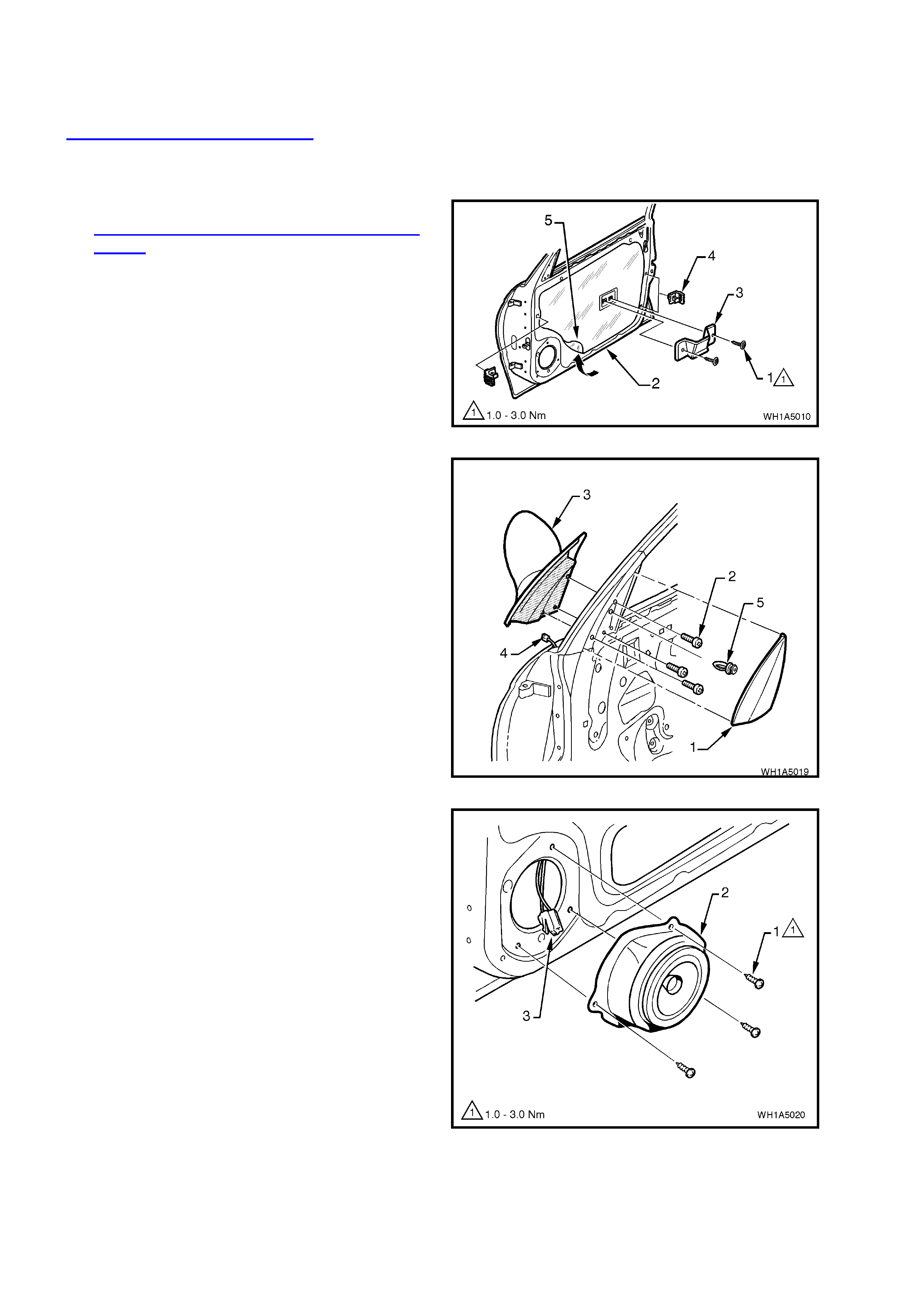
4. On front doors, remove the mirror inner cover
cap (1) by gently prying cap away from door.
5. Remove the three screws (2) securing the
external rear view mirror (3) to the door panel
and while supporting the mirror, disconnect the
wiring harness connector (4) and remove the
mirror.
Figure 1A5-30
6. Remove the three screws (1) securing the
speaker assembly (2) to the door inner panel,
remove speaker far enough to gain access to
wiring harness connec tor ( 3). Dis c onnect wiring
harness connector and remove speaker.
Figure 1A5-31
7. With window wound down approximately half
way, carefully pull drop window weatherstrip
from front guide rail (2).
NOTE: It is not necessary to remove drop window
weatherstrip completely, only from the front guide
rail.
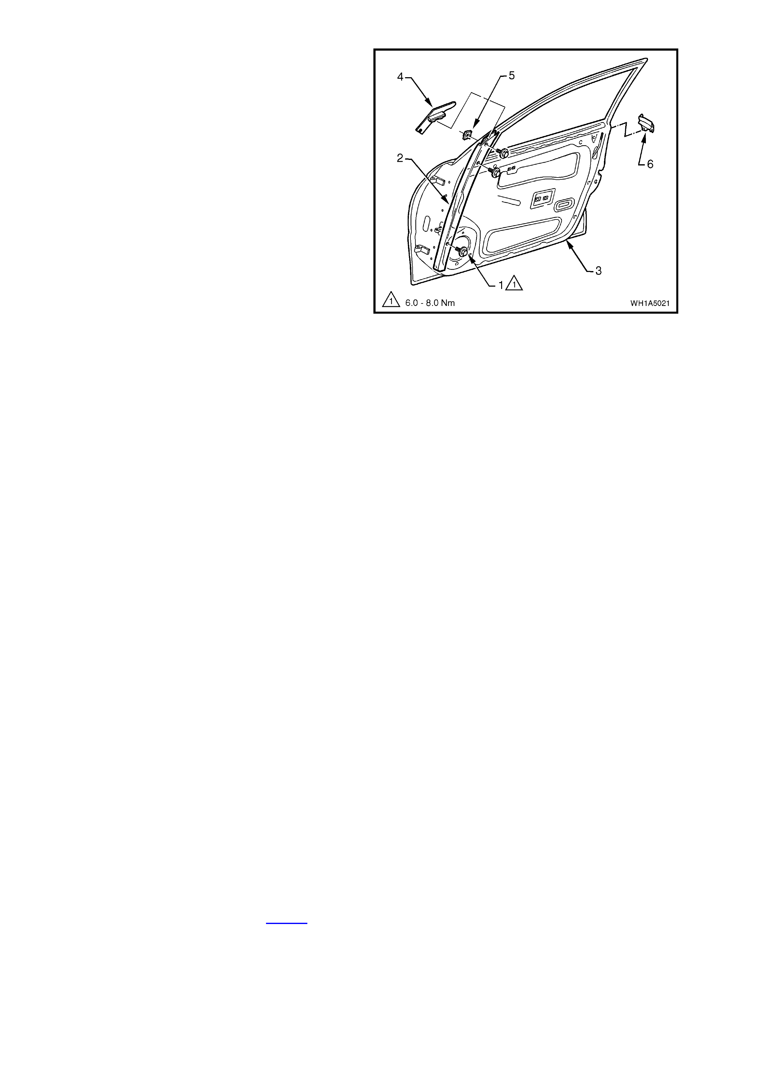
8. Remove the three bolts (1) securing the front
guide rail (2) to the door panel (3) and remove
guide rail downwards.
9. Rem ove guide rail cap (4) f rom top of guide rail
(2).
NOTE: The top guide rail retaining nut (5) is not
welded to the door and when the guide rail retaining
bolt is removed, this nut may become lost.
10. Gently pry the weatherstrip end cap (6) from
the rear of the door.
11. Remove the two attaching screws (2) securing
the window regulator guide rail (1) and slide the
rail out of window regulator guide runner, refer
to Fig. 1A5-33.
12. Disconnect window regulator wiring harness
connector from window regulator (4), refer to
Fig. 1A5-33.
13. While having an assistant support the window,
drill out rivets ( 4) sec uring the window regulator
to the door panel. Slide runners out of window
guide rails, and remove window regulator
through door inner panel aperture.
14. Remove the window assembly.
Figure 1A5-32
REINSTALL
Reinstallation of the front door window and
regulator assembly is the reverse of the removal
procedure, noting the following:
1. Ensure all frictional surfaces of the window
regulator assembly and associated parts are
adequately lubricated with Lithium grease (to
Holden Specification HN 1416).
2. Locate the regulator assembly inside the door,
aligning the attaching holes in the assembly
with the corresponding holes in the door inner
panel. Attach the regulator assembly to the
door inner panel using service replacement
screws.
3. Install front guide rail cap before tightening
front guide rail retaining bolt and nut.
4. Before installing door inner trim panel, adjust
the front door window and regulator as per the
following adjustment procedure
5. Ensure the water deflector is correctly sealed
against door inner panel.
6. Ensure the door remote control handle
assembly and remote control rod are engaged
before final fitment, refer to Fig. 1A5-27 in this
Section.
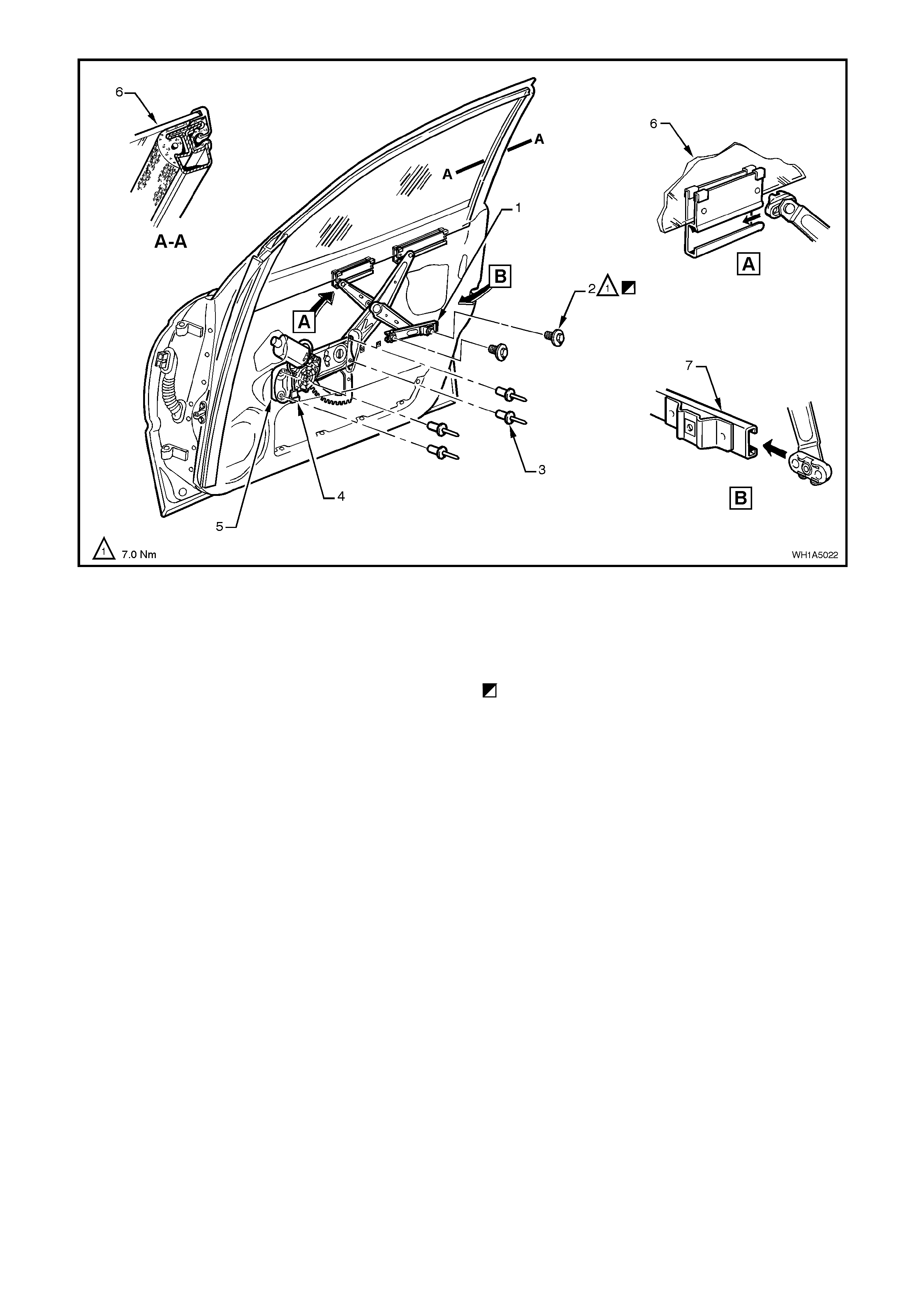
Figure 1A5-33
Legend
1. Window regulator guide rail.
2. Window regulator guide rail attaching screw (2
places).
3. Rivet (4 places).
4. Wiring harness connector.
5. window regulator assembly.
6. Glass assembly.
7. Window regulator guide rail lower.
Initial attachment to be loose, torque screw when
glass is installed and in down position, refer
adjustment procedure in the section.
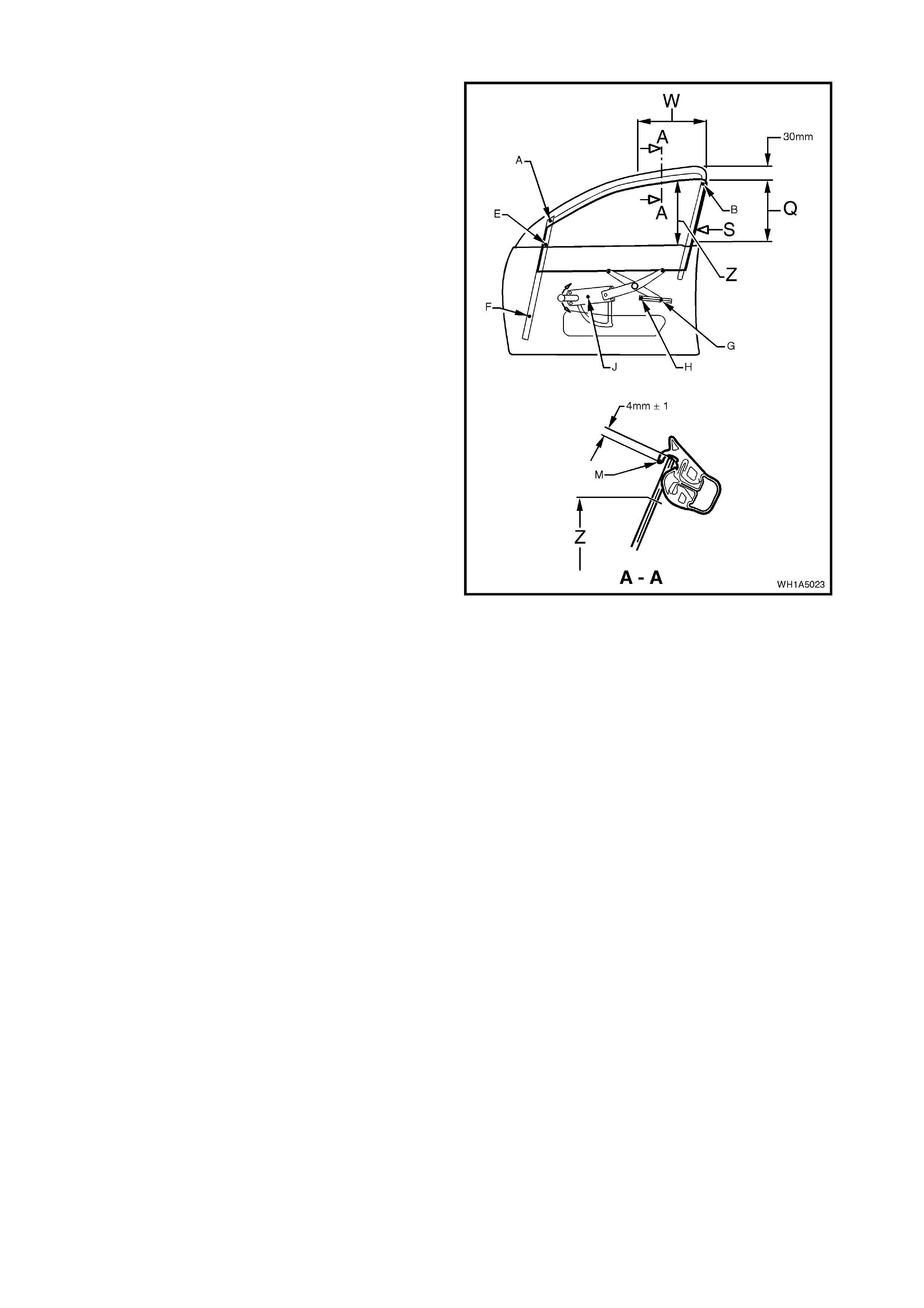
ADJUST
1. Adjust end stop, point ‘B’, at the rear of the door
so that there is a 1 mm gap below the highest
possible end stop position and tighten attac hing
screw to approximately 2 Nm.
2. Wind the window glass up through area ‘Q’
while at the same time, pressing the rail which
is bonded to the rear edge of the glass, in the
direction of arrow S. Continue winding window
glass up until window glass is appr oxim ately 30
mm before the closed position.
3. Screw window regulator guide rail in position
without imposing any stresses by tightening the
rear attachment screw, point ‘G’, to 7 Nm.
4. Tighten the centre attachment screw, point ‘E’,
of the front guide rail to 7 Nm while ensuring
that the window glass is held approximately 30
mm before the closed position.
5. Wind the window glass down to approximately
30 mm above the door belt moulding while at
the same time, pressing the rail which is
bonded to the rear edge of the glass, in the
direction of arrow S. Tighten the bottom
attachment screw, point ‘F’, for the front guide
rail to 7 Nm.
6. Screw window regulator guide rail in position
without imposing any stresses by tightening the
front attachment screw, point ‘H’, to 7 Nm.
7. Wind window glass up to a position where the
upper edge of the glass is flush with the upper
edge of the door mirror housing, as seen from
outside. In this position, the upper edge of the
glass m us t be parallel with point ‘M’ of the glass
run over area ‘W’.
8. Check cranking load of window glass in area Z.
If glass binds or motor load sounds excessive
re-adjus t window glass by correcting f ront guide
rail attachments, points ‘E’ and ‘F’.
9. Adjust end stop, point ‘A’, so that the end stop
contacts with the window glass and tighten
attaching screw to 7 Nm.
10. With the window in the closed position, adjust
end stop, point ‘J’, so that it contacts the
toothed sector of the window regulator, then
tighten attachment screw to 7 Nm.
11. Check upper edge of glass. If the deviation in
parallelism and engagement exceeds 1 mm,
re-adjust end stops at points ‘B’, and ‘A’ as
necessary, so that the upper edge of the glass
to the lip of the glas s run at point ‘M’ is within a
tolerance band of 3 to 5 mm.
Figure 1A5-34

12. Check the upper edge of the glass to ensure
that the lip of the glass run channel, point ‘M’, is
parallel over the area ‘W’.
The upper edge of the glass must be 4 mm
above the lip of the glass run channel, point ‘M’,
over the area ‘W’.
If either the deviation in parallelism or insertion
depth exceed 1 mm, then the end stops at
points ‘B’, and ‘A’, must be readjusted as
necessary so that the upper edge of the glass
is 3 to 5 mm above the lip of the glass run
channel, point ‘M’.
13. Tighten attachment screw for end stop, point
‘B’ to 4 Nm.

2.11 REAR DOOR WINDOW AND REGULATOR ASSEMBLY
NOTE: To remove, test and reinstall the power
window switch, depending on model variant, refer
to Section 12J-2 HIGH SERIES BCM of this
Service Information CD.
REMOVE
5. Wind rear window down.
6. Disconnect battery earth lead.
7. Remove the door inner trim panel refer to
2.4 FRONT AND REAR DOOR INNER TRIM
PANEL.
8. Remove inner trim retaining brackets (1) by
levering out the centre pin of bracket.
9. Carefully peel off the water deflector (2) from
the door inner panel (3).
10. Carefully pull the rear door drop window
weatherstrip from the upper door frame.
Figure 1A5-35
11. Remove the two screws (1) securing the guide
rail (2) to the top of the rear door.
12. Remove the two bolts (3) securing the guide
rail (2) to the door panel and remove guide rail
from door, outboard and upward.
13. Disconnect window regulator wiring harness
connector from window regulator (2), refer to
Fig. 1A5-37.
14. While having an assistant support the rear
window glass, drill out the rivets (1) securing
the window regulator assembly (3) to the door
inner panel. Slide the window regulator guide
runners (4) out of the window guides (5), and
remove window regulator through the aperture
in the door inner panel, refer to Fig. 1A5-37.
11. Remove door window glass.
Figure 1A5-36
REINSTALL
Reinstallation of the rear door window and
regulator assembly is the reverse of the removal
operation, noting the following:
15. Ensure all frictional surfaces of the window
regulator assembly and associated parts are
adequately lubricated with Lithium grease (to
Holden Specification HN 1416).
16. Locate the regulator assembly inside the door,
aligning the attaching holes in the assembly
with the corresponding holes in the door inner
panel. Attach the regulator assembly to the
door inner panel using service replacement
screws.
17. Before installing door inner trim panel, adjust
the front door window and regulator as per the
following adjustment procedure.
18. Ensure the water deflector is correctly sealed
against door inner panel.
19. Ensure the door remote handle assembly and
remote control rod are engaged before final
fitment, refer to Fig. 1A5-27 in this Section.
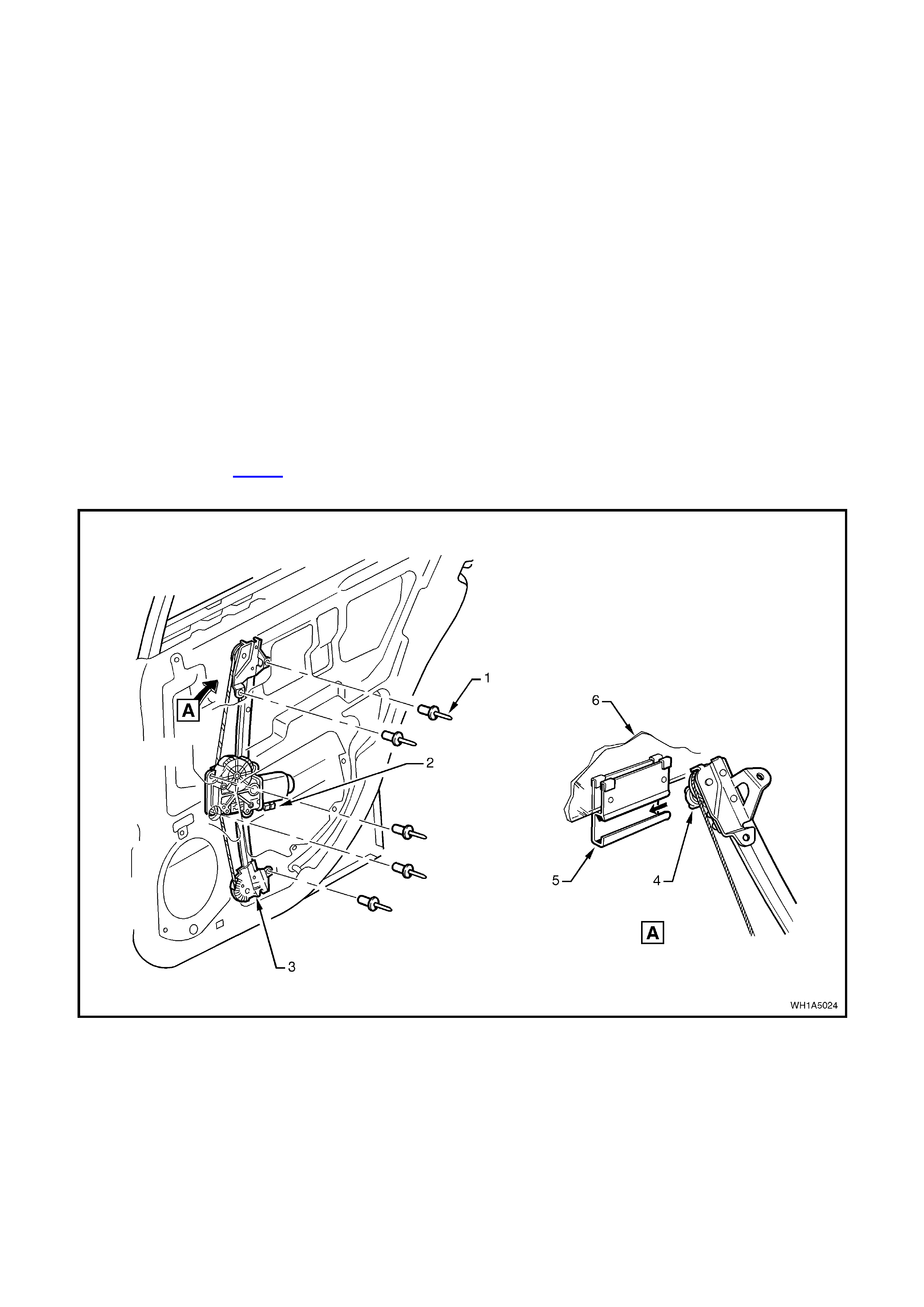
Figure 1A5-37
Legend
1. Rivet (5 places).
2. Window regulator wiring harness connector body.
3. Electric window regulator.
4. Guide runner.
5. Window guide.
6. Glass assembly.
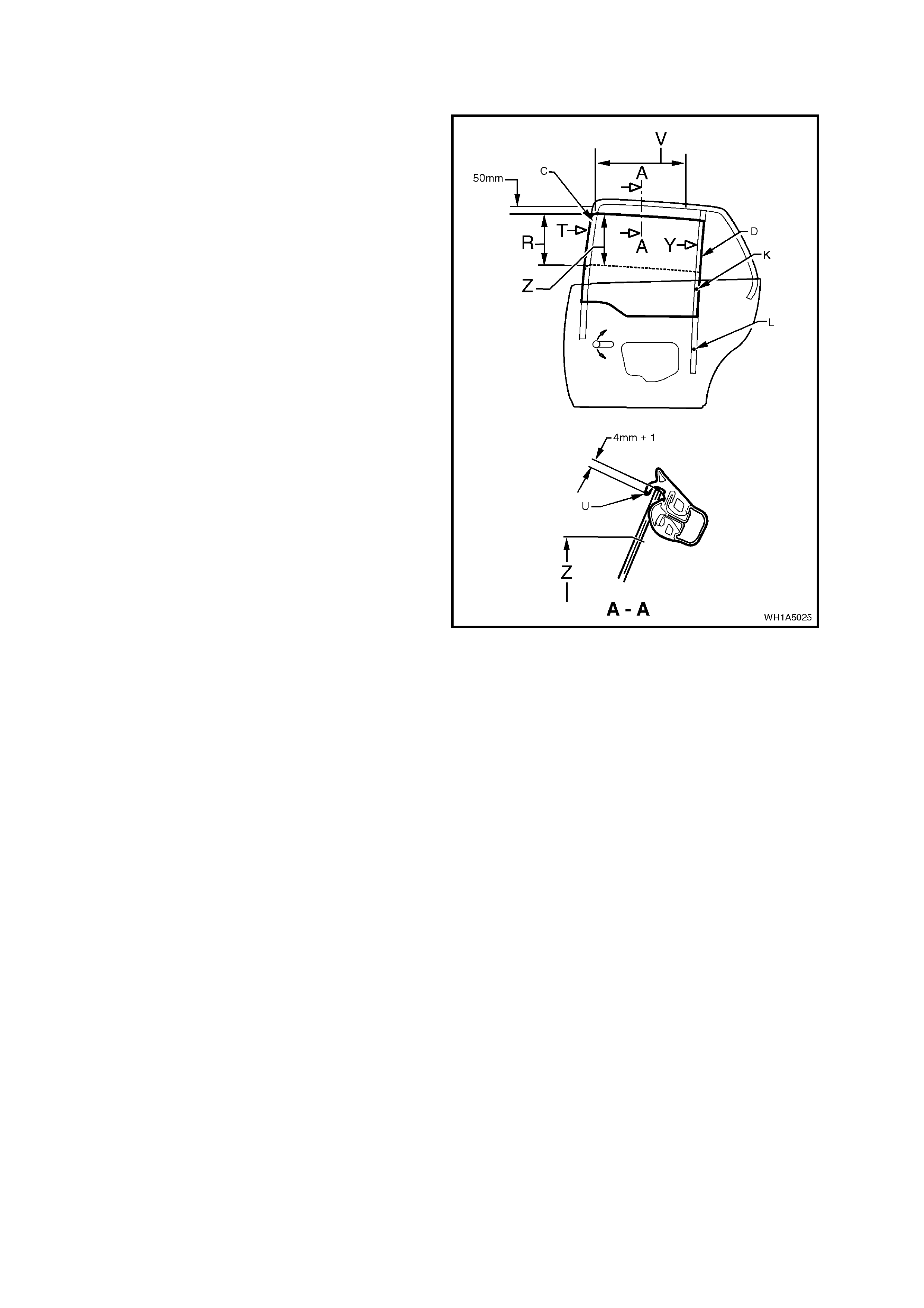
ADJUST
20. Tighten end stop point ‘D’ on the rear guide rail
to approximately 1 – 2 Nm.
21. Adjust end stop, point ‘C’, in the window frame
so that there is a 1 mm gap below the highest
possible end stop position and tighten attaching
screw to approximately 2 Nm.
22. Wind the window glass up through area ‘R’
while at the same time, pressing the rail which
is bonded to the front edge of the glass, in the
direction of arrow ‘T’. Continue winding window
glass up until window glass is appr oxim ately 30
mm before the closed position.
23. Push the rear guide rail rearward, in the
direction of arrow ‘Y’, and tighten guide rail
attachment screws, points ‘K’ and ‘L’ to 7 Nm.
24. Check crank ing load of window glass in area Z.
If glass binds or motor load sounds excessive
re-adjust window glass by correcting the rear
guide rail attachments, points ‘L’ and ‘K’.
25. Check upper edge of glass. If the deviation in
parallelism and engagement exceeds 1 mm,
re-adjust end stops at point ‘C’, and ‘D’ as
necessary, so that the upper edge of the glass
to the lip of the glass run at, point ‘U’ is within a
tolerance band of 3 to 5 mm.
26. Check the upper edge of the glass to ensure
that the lip of the glass r un channel, point ‘U’, is
parallel over the area ‘V’.
The upper edge of the glass must be 4 mm
above the lip of the glass r un channel, point ‘U’,
over the area ‘V’.
If either the deviation in parallelism or insertion
depth exceed 1 mm, then the end stops at
points ‘C’, and ‘D’ as necessary, must be
readjusted as necessary so that the upper
edge of the glass is 3 to 5 m m above the lip of
the glass run channel, point ‘U’.
27. Tighten attachment screw for end stops, point
‘C’ and ‘D’ to 4 Nm.
Figure 1A5-38
2.12 REAR DOOR FIXED WINDOW GLASS
REMOVE
1. Disconnect battery earth lead.
2. Remove the door inner trim panel refer to
2.4 FRONT AND REAR DOOR INNER TRIM
PANEL.
3. Remove inner trim retaining brackets (1) by
levering out the centre pin of bracket.
4. Carefully peel off the water deflector (2) from
the door inner panel (3).
Figure 1A5-39
5. Carefully pull the rear door drop window
weatherstrip from the rear guide rail.
6. Remove the two screws (1) securing the guide
rail (2) to the top of the rear door.
7. Remove the two bolts (3) securing the guide
rail (2) to the door panel and remove guide rail
from door, outboard and upward.
8. Prise the inner section of the fixed window
glass rubber from its position in the door upper
frame and slide glass toward front of vehicle,
removing the glass assembly.
Figure 1A5-40
REINSTALL
Reinstallation of rear door stationary window
assembly is reverse of removal operation.
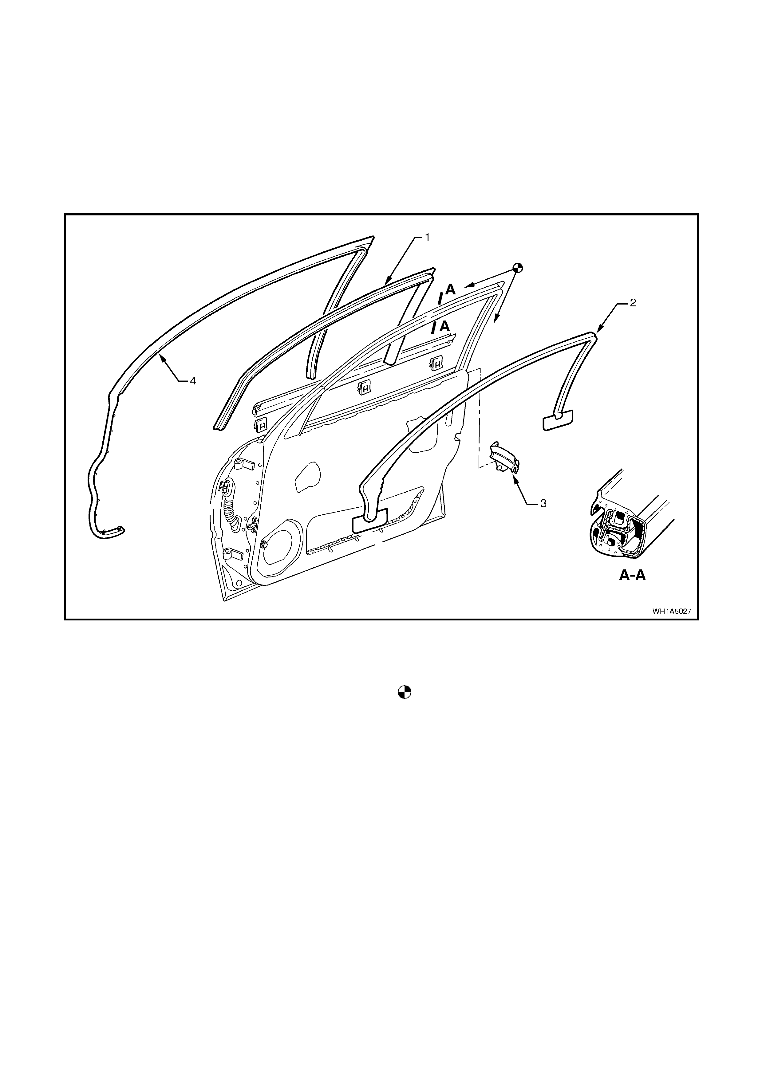
2.13 FRONT AND REAR DOOR UPPER WEATHERSTRIP ASSEMBLY
REMOVE
1. With the window glass lowered progressively
peel drop window weatherstrip (1) away from
around the door window frame and guide rails.
2. Progressively remove door weatherstrip (4)
from lip on door upper frame and the retainer
clips from holes in door panels. Refer to Figs.
1A5-41 (front door) or 1A5-42 (rear door ).
Figure 1A5-41
Legend
1. Drop glass weatherstrip.
2. Moulding.
3. End cap weatherstrip.
4. Door weatherstrip assembly.
Install weatherstrip corner aligning locating marks
on door frame, then proceed in direction of arrows.
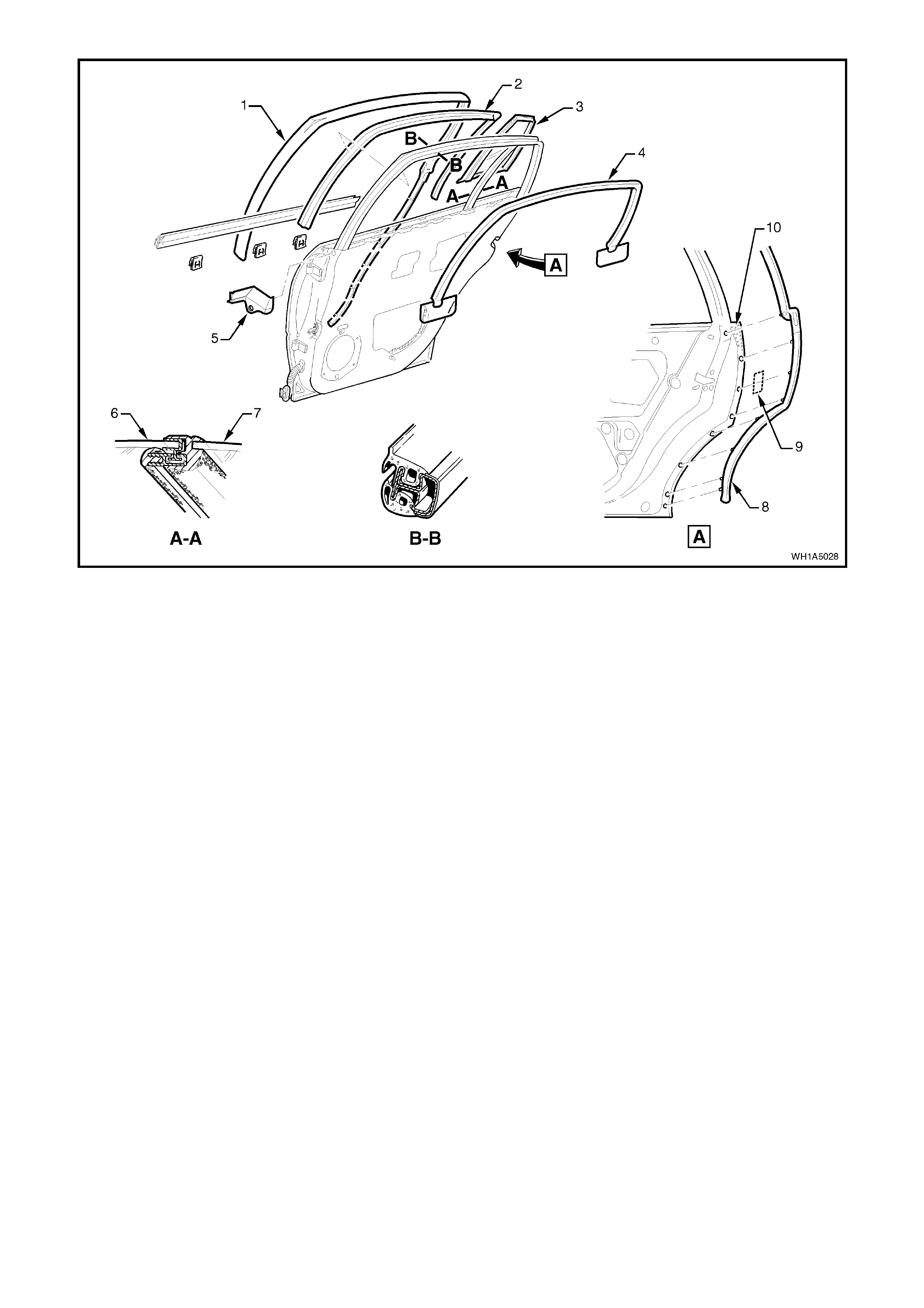
Figure 1A5-42
Legend
1. Door weatherstrip assembly.
2. Drop window weatherstrip.
3. Fixed window glass.
4. Moulding.
5. End cap weatherstrip.
6. Drop glass assembly.
7. Fixed glass.
8. Weatherstrip assembly
9. Tape.
10. Adhesive.
REINSTALL
Reinstallation is the reverse of rem oval operations,
noting the following:
When installing weatherstrips, start installation
process from the top corner of the door.
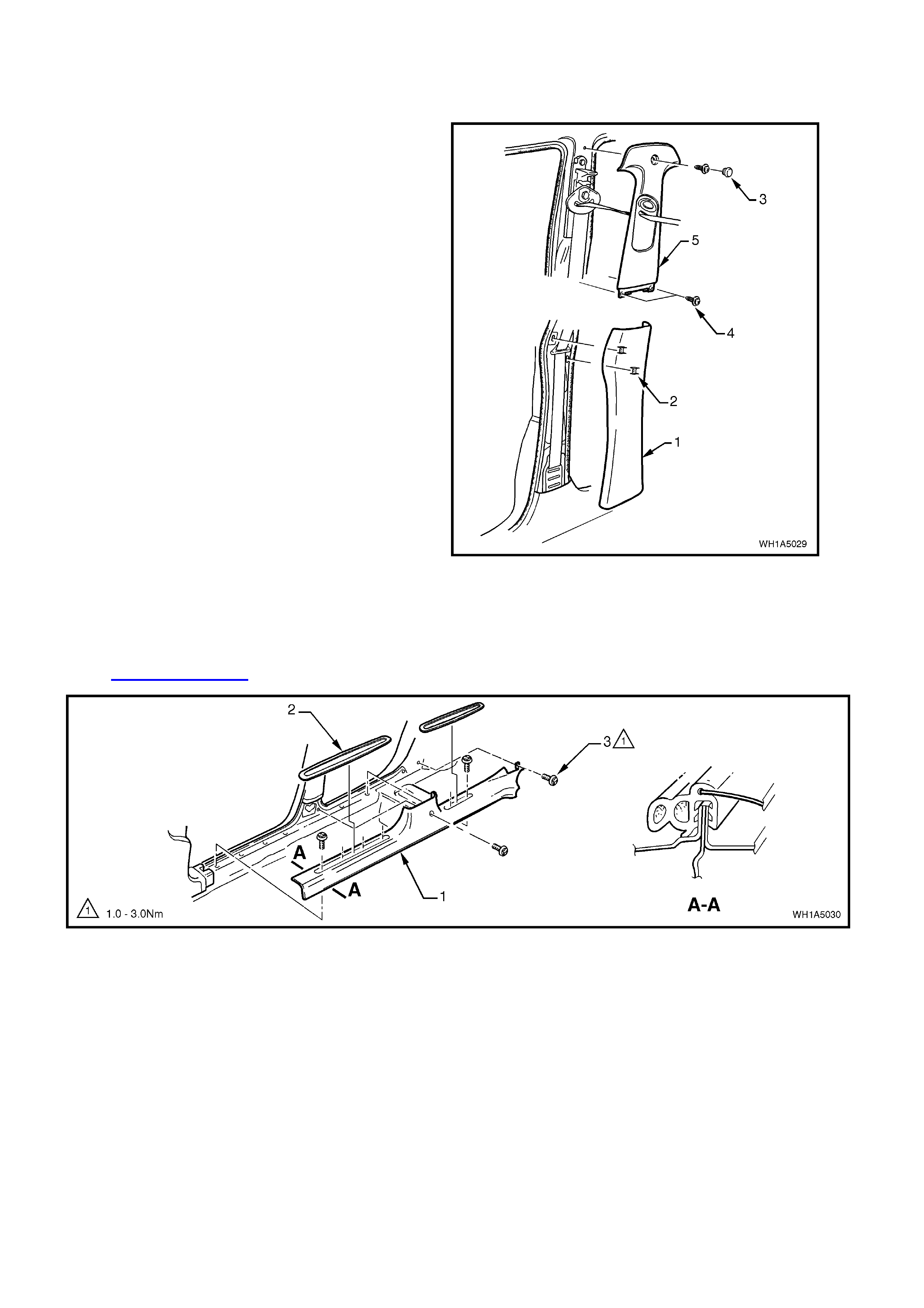
2.14 FRONT AND REAR DOOR OPENING WEATHERSTRIP
REMOVE
1. Unclip ‘B’ pillar lower trim (1) and remove
noting position of trim attaching clips (2).
Remove cap (3) and screws (4) securing ‘B’
pillar upper trim (5) and rem ove upper ‘B’ pillar
trim.
Figure 1A5-43
2. Remove inner rocker panel cover inserts (2)
and retainer screws (3), remove cover
assembly (1).
3. Remove the shroud lower trim assembly, refer
to Section 1A1 BODY.
Figure 1A5-44
4. Remove the assist grip handles, refer Section
1A8 HEADLINING AND REAR END TRIM.
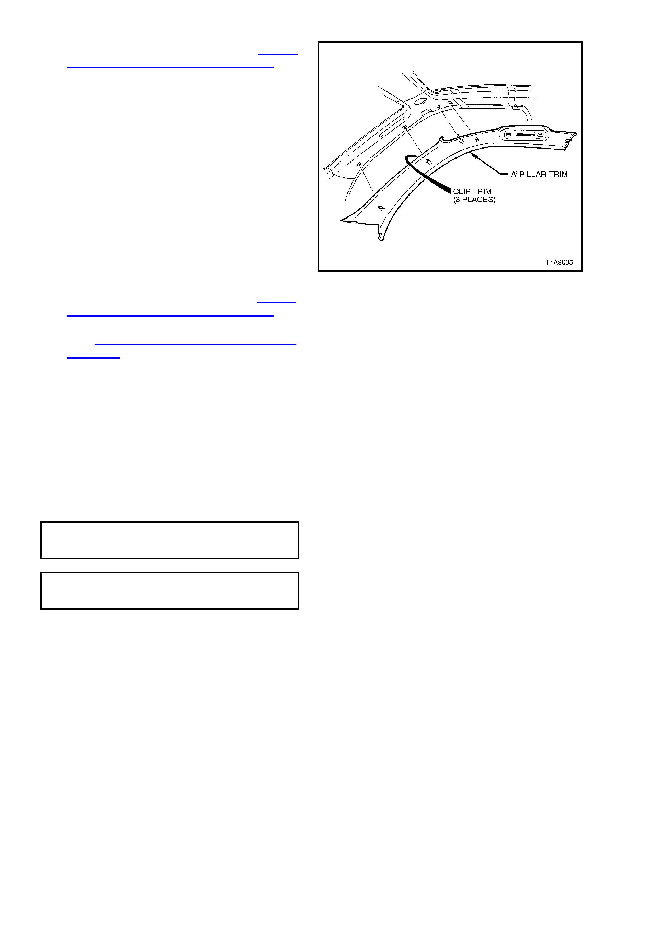
5. Carefully prise three clips attaching ‘A’ pillar
trim and remove ‘A’ pillar trim.
Figure 1A8-45
6. Remove the rear reading lamps refer Section
1A8 HEADLINING AND REAR END TRIM.
7. Rem ove the rear ‘C’ pillar upper and lower trim
refer Section 1A8 HEADLINING AND REAR
END TRIM.
8. Gently prise weatherstrip from door opening.
REINSTALL
Reinstallation of the door opening weatherstrips is
the reverse of the removal procedure, noting the
following:
1. Align identification mark on weatherstrip with
the check link bracket, refer to Fig. 1A5-46.
2. Ensure weatherstrip lip sits over trim panels.
3. Tighten all screws to the correct torque
specification.
CENTRE PILLAR UPPER TRIM
RETAINING SCREW
TORQUE SPECIFICATION 1 - 3 Nm
ROCKER PANEL
RETAINING SCREW
TORQUE SPECIFICATION 1 - 3 Nm
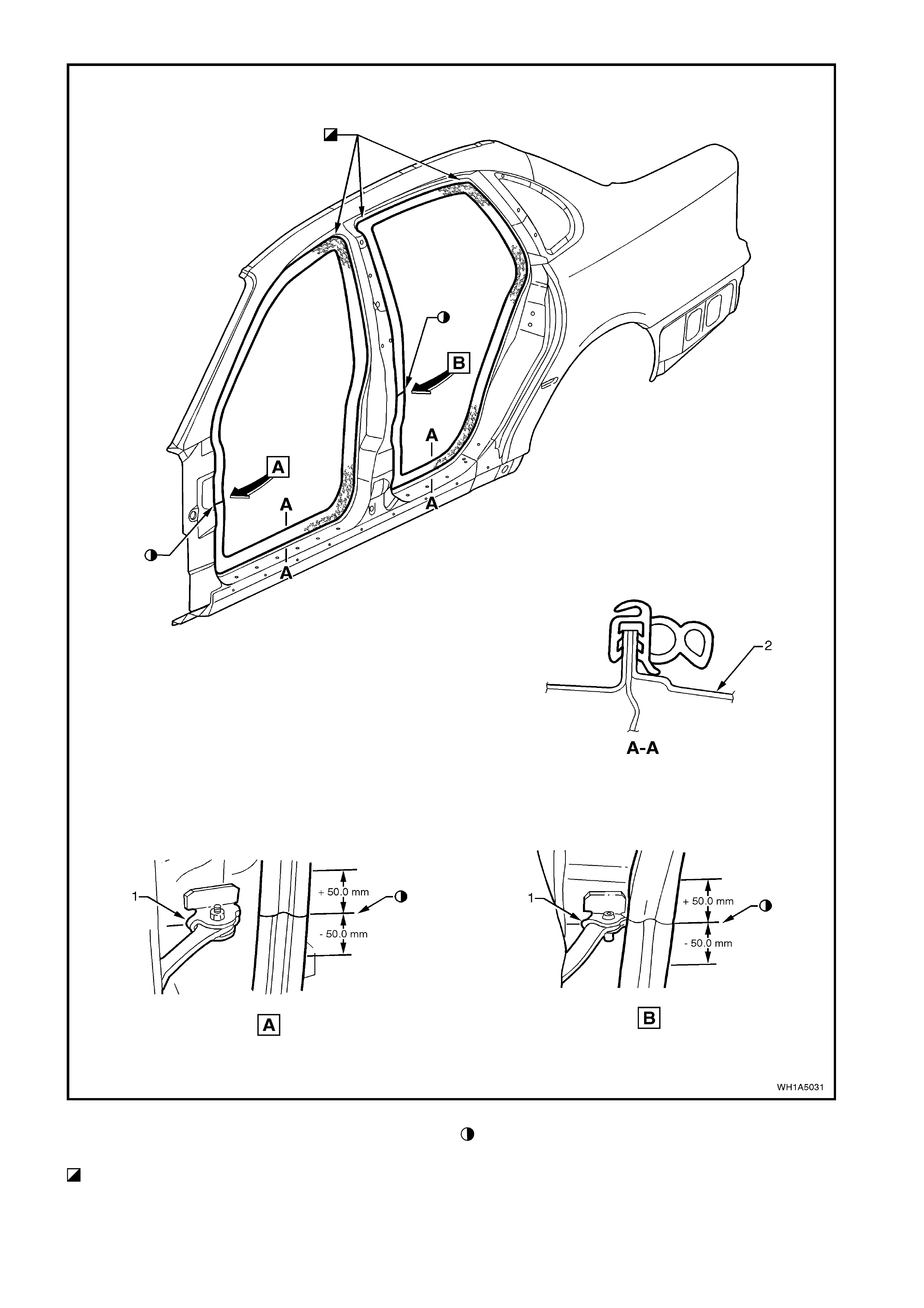
Figure 1A5-46
1. Check link hinge.
2. Door opening frame.
Allow crowding of weatherstrip in corners, ensure
weatherstrip does not short cut corners and foul door
trim.
Ensure joint of weatherstrip is centrally located on
vertical flange of ‘A’ & ‘B’ pillar door opening frames ±
50,0 mm as shown.
2.15 FRONT AND REAR DOOR BELT WEATHERSTRIP AND MOULDING ASSEMBLY
REMOVE
1. Front doors; remove the rear vision mirror
assembly, refer to 2.16 EXTERIOR REAR
VISION MIRROR ASSEMBLY.
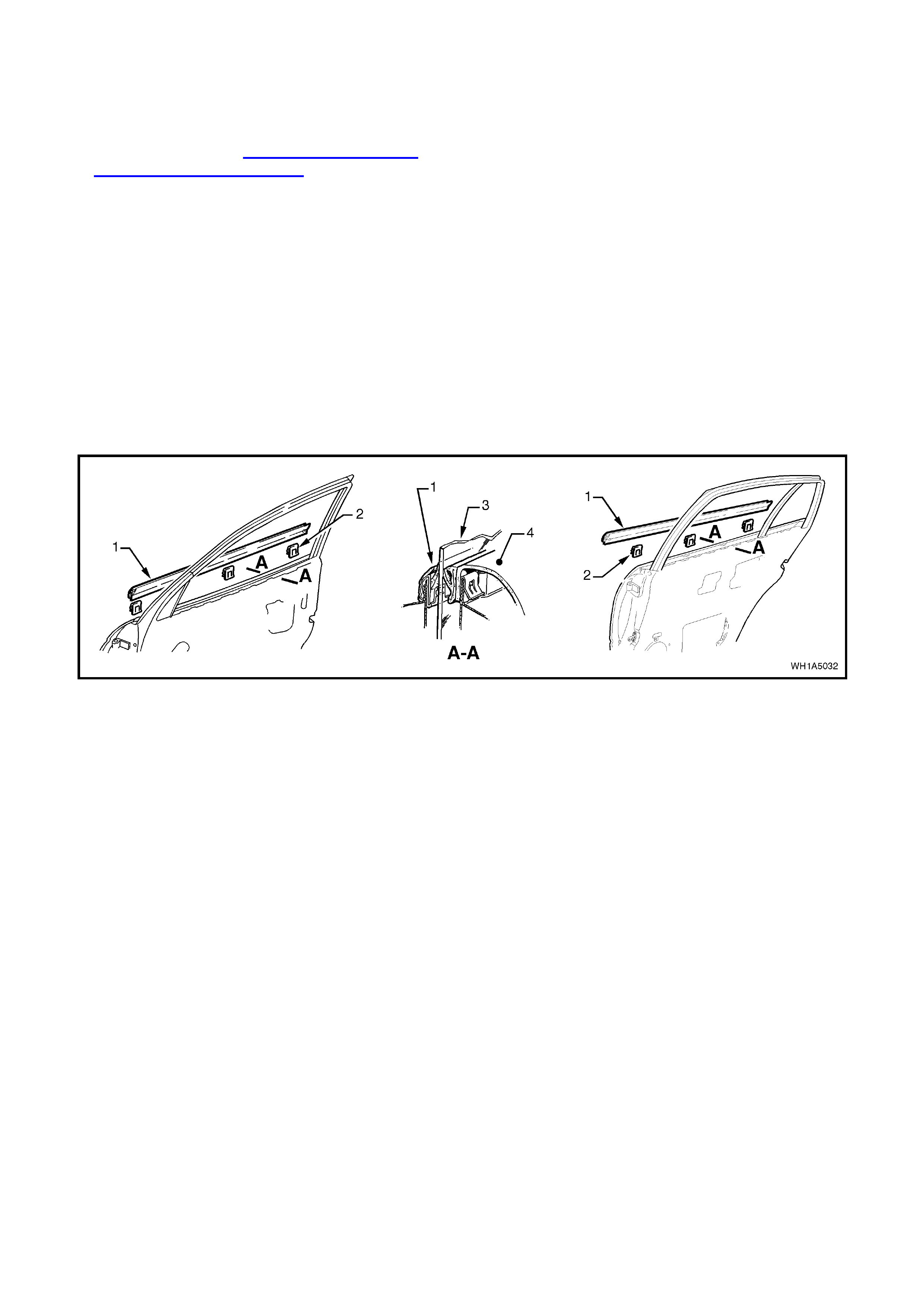
2. Prise the weatherstrip and moulding assembly
(1) of f the door us ing fingers , tak ing care not to
damage moulding.
REINSTALL
Reinstallation of the door belt weatherstrip and
moulding assembly is the reverse of the removal
operations, noting the following:
1. Locate the door belt weatherstr ip and m oulding
assembly over the top of the door outer panel,
then using palm of the hand, firmly tap the
assembly down, over the door outer upper
flange.
Figure 1A5-47
Legend
1. Front door belt weatherstrip and moulding assembly.
2. Clip (3 places). 3. Glass assembly.
4. Door inner trim.
2.16 EXTERIOR REAR VISION MIRROR ASSEMBLY
REMOVE
NOTE: For further information regarding the
external rear vision mirror, refer to Section 12H
ELECTRICALLY ADJUSTABLE REAR VISION
MIRRORS of this Service Information CD.
1. Disconnect battery earth lead.
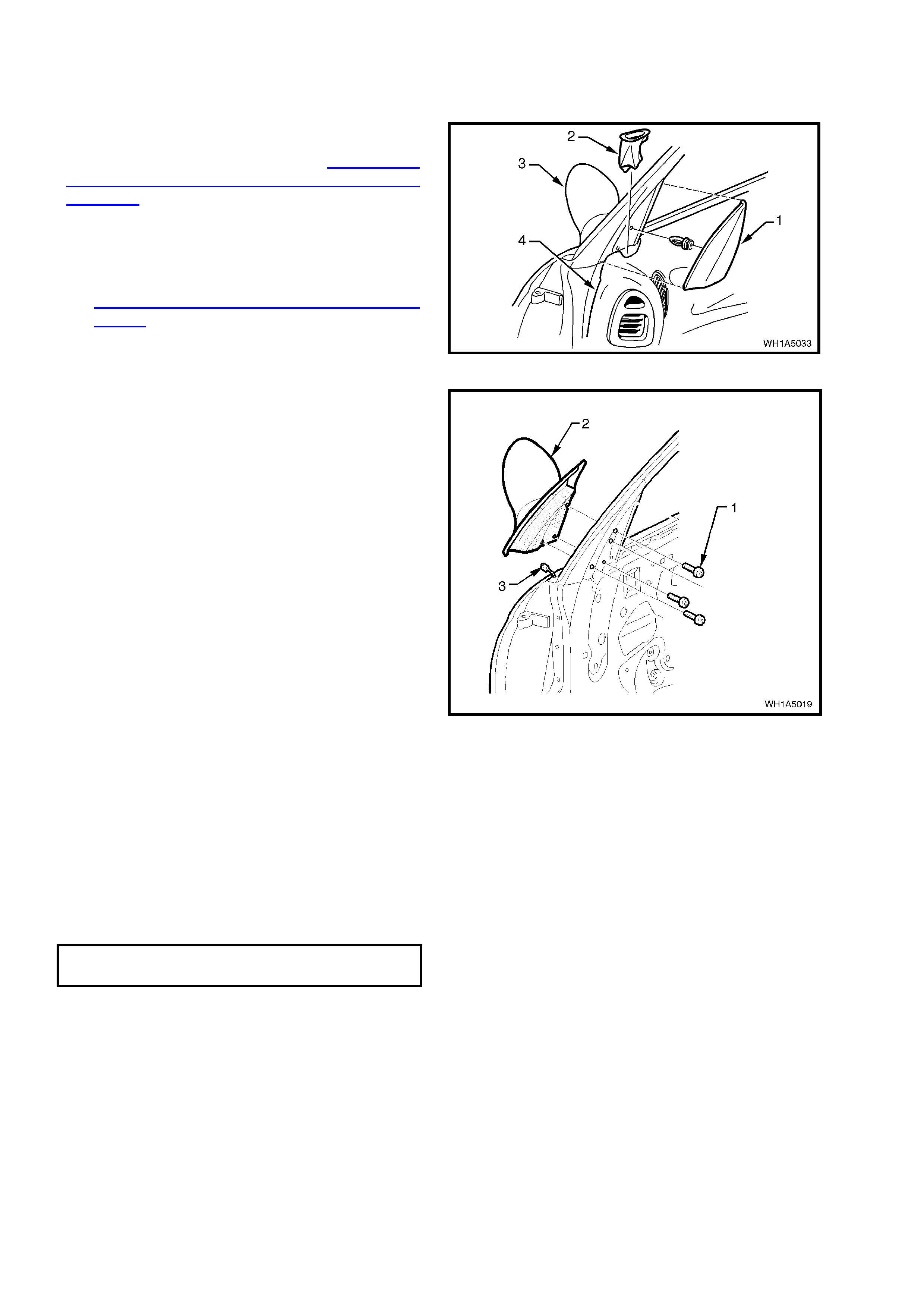
2. Remove the mirror inner cover cap by gently
pryi ng cap away from door.
3. Remove the front door inner trim panel refer
2.4 FRONT AND REAR DOOR INNER TRIM
PANEL in this Section.
Figure 1A5-48
4. Remove the three screws (1) securing the
mirror (2) to the door and while supporting the
mirror, disconnect the mirror wiring harness
connector (3).
5. Remove mirro r assembly.
Figure 1A5-49
REINSTALL
Reinstallation of the exterior rear vision mirror is
the reverse of the removal operation, noting the
following:
1. Ensure wiring harness and connector for the
mirror are correctly routed.
2. Ensure the three mirror to door securing
screws are tightened to the correct torque
specification.
MIRROR TO DOOR SECURING
SCREW TORQUE SPECIFICATION 2.5 - 3.0 Nm
3. Ensure that when installing the door demist
duct, that it clips into position.
4. Replace mirror inner cover retaining clip.
2.17 DOOR CHECK LINK ASSEMBLY
REMOVE
1. Remove the s crew (1) from the door check link
support.
NOTE: Ensure door cannot swing freely causing
damage.
2. Remove check link retaining screws removing
check link assembly.
Figure 1A5-50
REINSTALL
Reverse removal operations.
DOOR CHECK LINK SECURING
SCREW TORQUE SPECIFICATION 5.0 - 7.0 Nm
Techline
2.18 SWITCH - ELECTRIC EXTERIOR REAR VISION MIRROR CONTROL
NOTE: For further information regarding the
external rear vision mirror and switch, refer to
Section 12H ELECTRICALLY ADJUSTABLE
REAR VISION MIRRORS of this Service
Information CD.
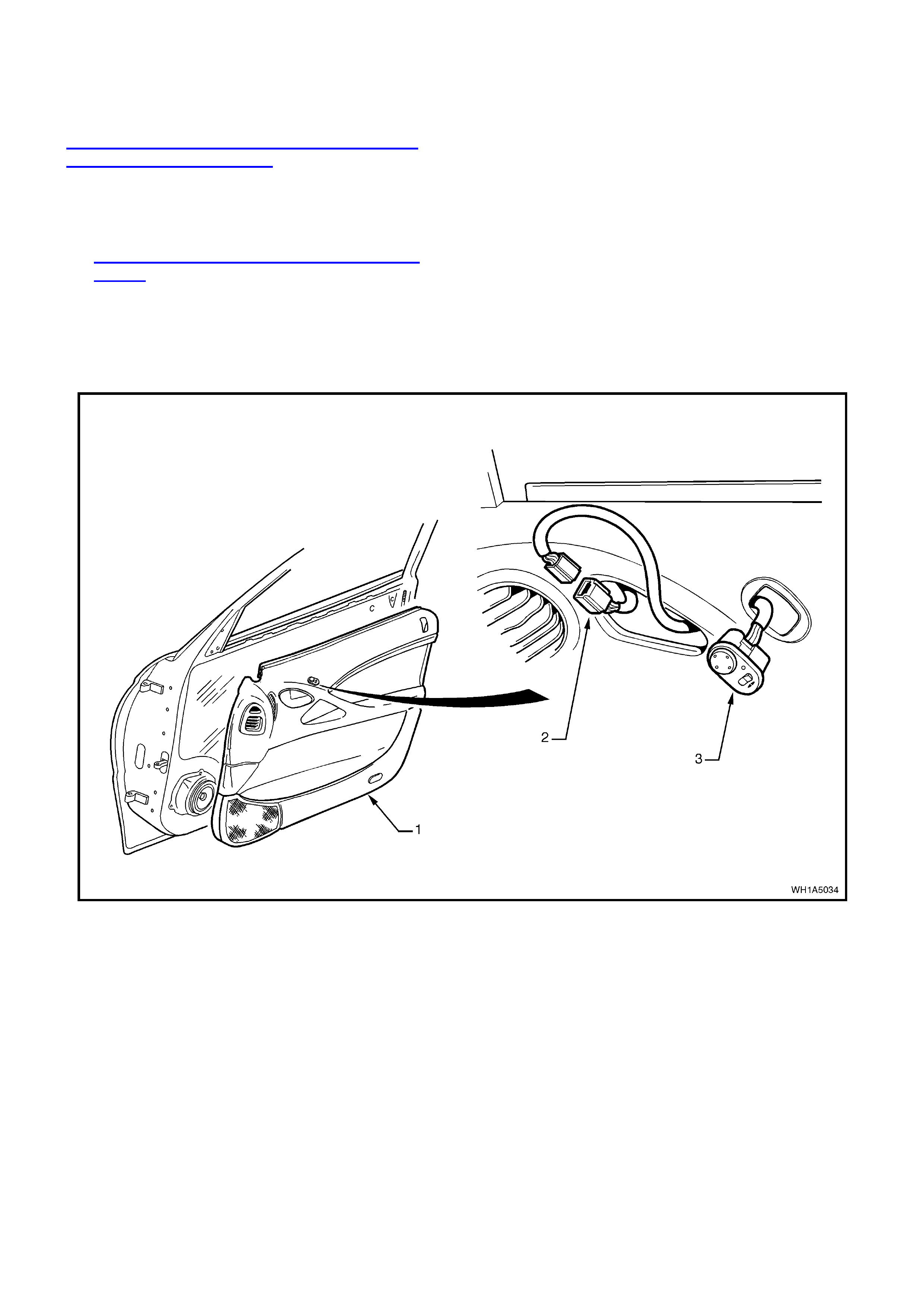
REMOVE
1. Remove door inner trim panel (1), refer to
2.4 FRONT AND REAR DOOR INNER TRIM
PANEL.
2. Disconnect the door elec trical harnes s f rom the
control swit ch harness assembly (2).
3. From inside of door trim assembly, push the
control switch (3) free and remove the switch.
Figure 1A5-51
REINSTALL
Reinstallation of the exterior rear vision mirror
control switch is the reverse of the removal
operation.

3. TORQUE WRENCH SPECIFI CATIONS
Nm
Door inner trim panel retaining screw................................... 1.0 - 3.0
Door inner trim panel retaining bracket screw...................... 1.0 - 3.0
Door lock and actuator assembly retaining screw................ 3.0 - 5.0
Door locking button escutcheon retaining screw .................. 1.0 - 3.0
Door remote handle assembly retaining screw..................... 1.0 - 3.0
Exterior rear vision mirror to door panel screw..................... 2.5 - 3.0
Front exterior door handle retaining nut................................ 3.0 - 5.0
Front guide rail retaining bolt ................................................ 2.5 - 3.5
Rear door guide rail attachment bolt..................................... 0.5 - 2.0
Rear door guide rail attachment screw................................. 6.0 - 14.0
Rear exterior door handle retaining nut ................................ 3.0 - 5.0
Speaker assembly retaining screw....................................... 1.0 - 3.0
Striker assembly retaining bolt.............................................. 8.0 - 18.0
Window regulator guide rail attaching screw........................ 7.0
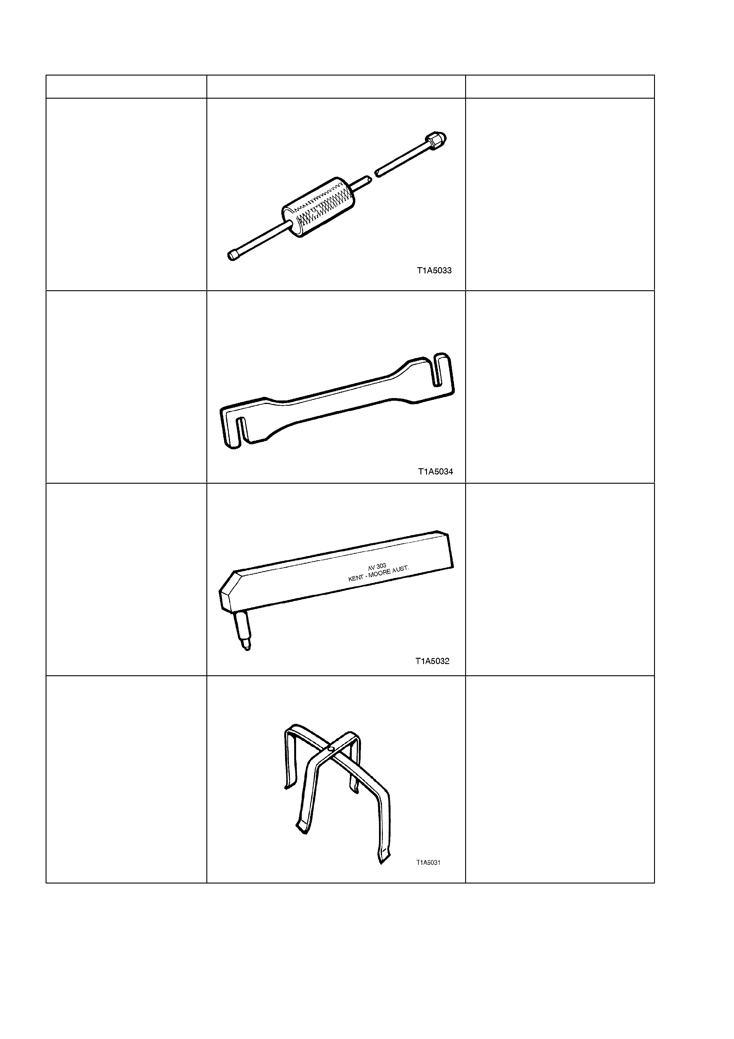
4. SPECIAL TOOLS
TOOL NO. REF IN TEXT TOOL DESCRIPTION COMMENTS
AU170 DOOR HINGE PIN REMOVAL TOOL PREVIOUSLY RELEASED
FOR
‘V’ CAR
AU184 DOOR HINGE SETTING TOOL
For front and rear door alignment PREVIOUSLY RELEASED
FOR
‘V’ CAR
AU303 DOOR HINGE SLEEVE INSTALLER PREVIOUSLY RELEASED
FOR
‘V’ CAR
AU455 CONNECTOR BODY REMOVER
To remove the door wiring harness
connector from A and B pillars.
MANDATORY TOOL