
SECTION 1A7 - SEAT AND SEAT BELT ASSEMBLIES
IMPORTANT
Before performing any Service Operation or other procedure described in this Section, refer to
Section 00 CAUTIONS AND NOTES for correct workshop practices with regard to safety and/or
property damage.
1. GENERAL I NFORMATIO N
The WH Series Statesman and Caprice are fitted with eight-way electrically adjustable driver and front passenger
seats, which also include side impact air bags. In addition, the driver’s seat in the Caprice is fitted with an integrated
memory seat and mirror system which is controlled from a series of buttons located on the side of the driver’s seat.
On key-less entry to the vehicle, the memory seat and mirror system in conjunction with the Body Control Module
(BCM) recognises which ignition key has been used (Priority 1 or Priority 2) and adjusts the seat and external
mirrors accordingly.
The memory seat and mirror system allows the driver to adjust the seat position to any of the positions stored in
memory by pressing one of the control buttons. If reverse gear is selected and the mirror dip button pressed, the
passenger’s side external mirror will automatically dip to a preset position providing a different view of the
passenger’s side of the vehicle during reversing.
Audio and visual feedback for the various functions of the memory seat and mirror system is provided. The system
has a green LED and an audio chime located in the seat assembly which are used to indicate memory saves, the
recall of priority memory numbers and for seat diagnostic procedures.
The external rear vision mirrors on the Caprice are heated, and operate in conjunction with the heated rear window.
The centre rear head restraint is now fitted with a release button to allow downward travel of the head restraint. This
release button is the same type as that fitted to the other head restraints.
This Section should be read in conjunction with Section 1A7 SEAT & SEAT BELT ASSEMBLIES in the VT Series
II Service Information, as well as Section 1A7 SEAT & SEAT BELT ASSEMBLIES in the VT Series I Service
Information.
IMPORTANT: Some of the procedures detailed in 3.6 DIAGNOSTIC PROCEDURES require the use of both the
Priority 1 Key and the Priority 2 Key.
CAUTION: Accessory and after market seat covers MUST NOT be fitted to any vehicle with side air bags
unless approved by Holden. Non-approved seat covers may inhibit the operation of the side air bag,
reducing the protection otherwise provided to the occupants during a side-impact collision.
Techline
Techline
Techline
Techline
Techline
Techline

1.1 GENERAL DESCRIPTION
SEAT A SSEMBLY
Each seat contains four electric, reversible motors. The height of both the front and rear of the seat is controlled by
separate lift motor and gearbox assemblies. Each motor can be operated independently of the other, or operated
together to raise or lower the complete seat assembly. A separate fore/aft movement motor and two gearboxes
control seat forward or rearward positioning. The fourth motor controls the seat backrest recliner position.
Each lift motor and gearbox assembly is bolted to one side of the seat height adjust assembly and when each lift
motor is operating, the lift motor drives the gearbox, which then draws in or extends out the mating worm shaft
which in turn operates on a lever and cross-brace. The cross-brace is connected to another lever on the opposite
side of the seat height adjust assembly and this allows the raising or lowering of that section of the seat. Reversing
the polarity on the lift motor terminals causes the motor to operate in the reverse direction and the seat moves in the
opposite direction.
To control seat fore/aft movement, a worm shaft is attached to each seat rail with the movement motor and
gearboxes attached to the seat height adjust assembly.
When the movement motor is operating, the gearboxes (driven by the movement motor) draw in or extend out each
mating worm shaft. Since each worm shaft is held from moving, the action of the gearboxes meshing with the worm
shafts causes the seat to move (via the seat height adjust assembly) in one direction. Reversing the polarity on the
movement motor terminals causes the motor to operate in the reverse direction and the seat moves in the opposite
direction.
Seat backrest recliner angle is adjusted by a recliner motor attached to the inner seat backrest frame. The motor
output shaft has a drive gear which is meshed with a driven gear attached to the seat backrest frame. Motor
operation causes rotation of the drive gear which turns the driven gear and seat backrest frame, thereby altering the
seat backrest recliner angle. Reversing the polarity on the recliner motor terminals causes the motor to drive in the
reverse direction and the seat backrest moves in the opposite direction.
The driver's seat also contains a seat control module under the lower side cover. The seat control module has a
non-volatile memory , so that removing the battery supply from the module does not erase the seat memory settings.
The lift, movement and recliner motors are common between each seat, except that each motor on the driver's seat
has a potentiometer attached. The potentiometers are used as seat position sensors by the memory seat and mirror
system. The wiring harnesses used for the passenger's side and driver's side seats are different.
Watchdog timers in the memory seat and mirror system limit the time a seat drive motor can operate. The lift and
movement motors are limited to 25 seconds, while the recliner motor is limited to 50 seconds.
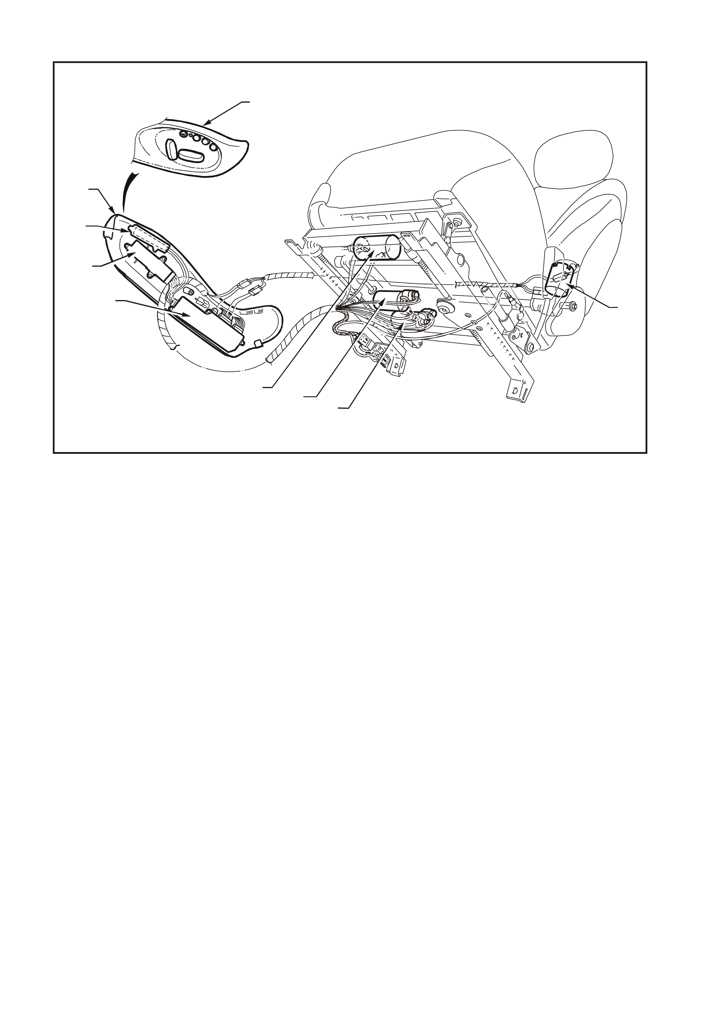
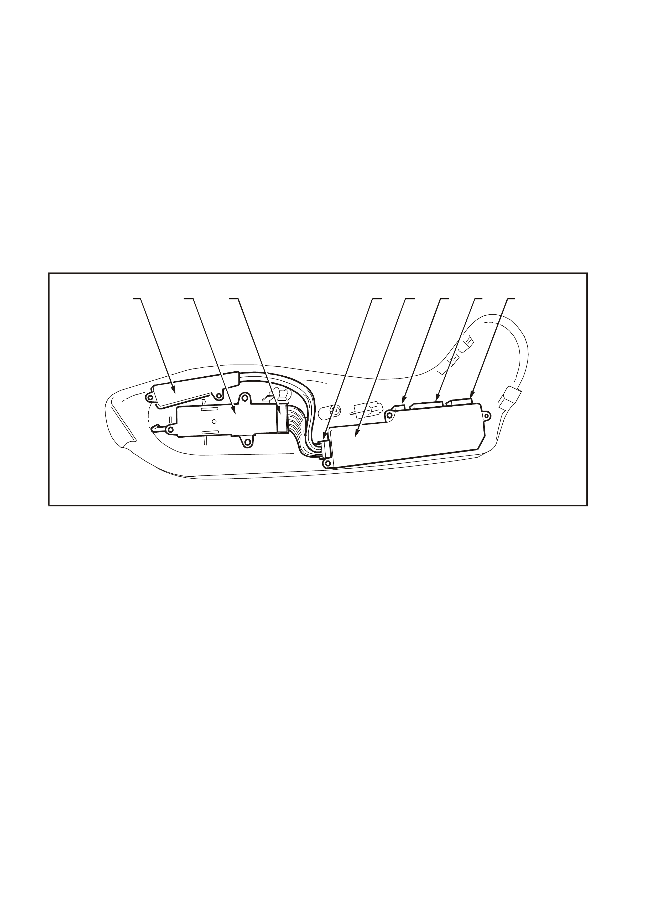
Fig. 1A7-1 illustrates the seat, seat controls and drive motors.
WH1A7001
1
2
3
9
2
3
4
5
8
67
1
Figure 1A7-1
1. Seat Controls 4. Eight-way Seat Position Switch 7. Front Up/Down Drive Motor (Lift Motor)
2. Seat Lower Side Cover 5. Seat Control Module 8. Rear Up/Down Drive Motor (Lift Motor)
3. Memory Position Switch 6. Fore/Aft Drive Motor 9. Backrest Recliner Angle Drive Motor

MEMORY SEAT AND MIRROR SYSTEM
The memory seat and mirror system comprises:
• the seat control module located under the seat lower side cover (refer to Fig. 1A7-1);
• the memory position switch, which includes memory and mirror dip buttons and associated LED, located on the
side of the driver’s seat (refer to Fig. 1A7-2);
• the external rear vision mirrors;
• the mirror switch module located in the driver’s door; and
• the mirror switch located on the driver’s door.
The seat control module has five memory sets which allows up to five individual seat and mirror settings to be
stored. Two of these memory settings are associated with the priority keys and the remaining three settings
correspond to the memory buttons 1, 2 and 3 located on the side of the driver’s seat.
The memory seat and mirror system has two modes of operation; a low-current sleep mode and an awake mode. A
5 minute timer circuit switches the system between modes as required, and the current mode is indicated by the
green LED on the side of the seat. When the LED is illuminated the system is in awake mode, and when the LED is
extinguished, the system is in sleep mode.
The sleep mode is entered when:
• the ignition key is in the OFF position, and
• there are no active priority signals, and
• there are no manual seat or mirror adjustments for 5 minutes.
The awake mode is entered when:
• the ignition key is in the IGN position, or
• the priority signals are active, or
• there is a manual seat adjustment, or
• a seat memory button is pressed, or
• the mirror dip button is pressed.
Entering the awake mode resets the 5 minute timer.
Memory Sets
There are five memory sets, as follows:
• Memory set P1 – Priority Key 1,
• Memory set P2 – Priority Key 2,
• Memory set 1 – Button 1 on seat,
• Memory set 2 – Button 2 on seat, and
• Memory set 3 – Button 3 on seat.
Each memory set comprises the following information:
• four co-ordinates for the seat position (in seat control module),
• the mirror dip status (on / off) (in seat control module),
• two co-ordinates for the normal mirror position (in mirror module for each mirror), and
• two co-ordinates for the mirror dip position (in mirror module for each mirror).
Memory Buttons
The three memory buttons and the associated LED are located on the seat lower side cover close to the front edge
of the seat (refer to Fig. 1A7-2). The memory buttons are labelled 1, 2 and 3.
Pressing button 1, 2 or 3 for less than 2 seconds activates the memory recall on release of that button. A low chime
acknowledges the initial button press. The one-touch button recall is only active when the vehicle ignition switch is in
the OFF or ACC position.
Pressing button 1, 2 or 3 for more than 2 seconds updates the system’s memory to the current seat and mirror
positions for that button, including mirror dip positions and status. A high chime acknowledges the system save.
Memory updating is active irrespective of the ignition switch position.
For safety reasons, no memory button recall is allowed when the ignition is on. If a recall is initiated and the ignition
then set to on, the seat and mirror movement recalled from memory will continue until completed.
Pressing any other button, including the mirror switch on the driver’s door, after a memory recall is initiated will
terminate the recall move.
WH1A7002
123
65
7
4
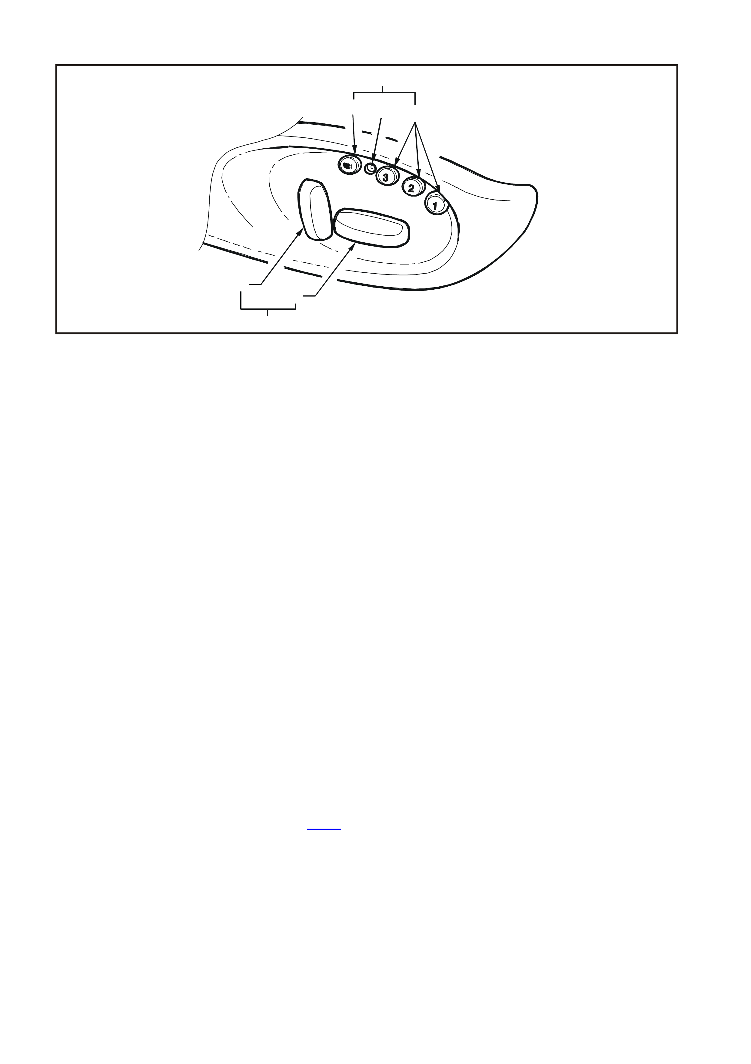
Figure 1A7-2
1. Mirror Dip Button 4. Memory Position Switch 6. Backrest Recliner Angle Adjust
2. Diagnostic LED 5. Fore/Aft/Up/Down/Tilt Adjust 7. Eight-way Seat Position Switch
3. Memory Buttons
Reversing Mirror Dip Function
The mirror dip button is located on the lower seat cover to the rear of the memory buttons and LED (refer to Fig.
1A7-2). The mirror dip button is labelled with a mirror graphic.
The mirror dip button is only active when the ignition is on and reverse gear is selected. Pressing the mirror dip
button toggles the internal mirror dip flag, which initiates a high chime for enabled, or a low chime for disabled.
With the ignition on and the mirror dip flag enabled, selecting reverse gear for longer than 0.5 second sets the
passenger’s external mirror to the dip position. Pressing the button again, or selecting another gear, returns the
mirror to the normal driving position.
Priority Function
The priority recall signals generated by the BCM wake up the memory seat and mirror system to recall the last
saved priority seat and mirror positions associated with the ignition key in use (Priority 1 or Priority 2).
For safety reasons, the priority recall function is activated only when the ignition switch is in the OFF position. No
automatic movement of the system occurs when the ignition switch is set to IGN. If a priority move has been
initiated before the ignition transition from OFF to IGN, the system completes the move before disabling the one-
touch or priority recall function.
After the ignition switch is set to IGN, the system notes the active priority key number used. The system only
updates the current memory when the driver makes a manual adjustment to the seat or mirrors. The update
includes the current seat and mirror position and the last reverse mirror dip position.
When the seat or mirror is adjusted by the driver using the manual buttons, the current priority memory is updated
immediately after the movement stops. Toggling the mirror dip button does not alter the stored normal or dip
settings.
Module Control Signals
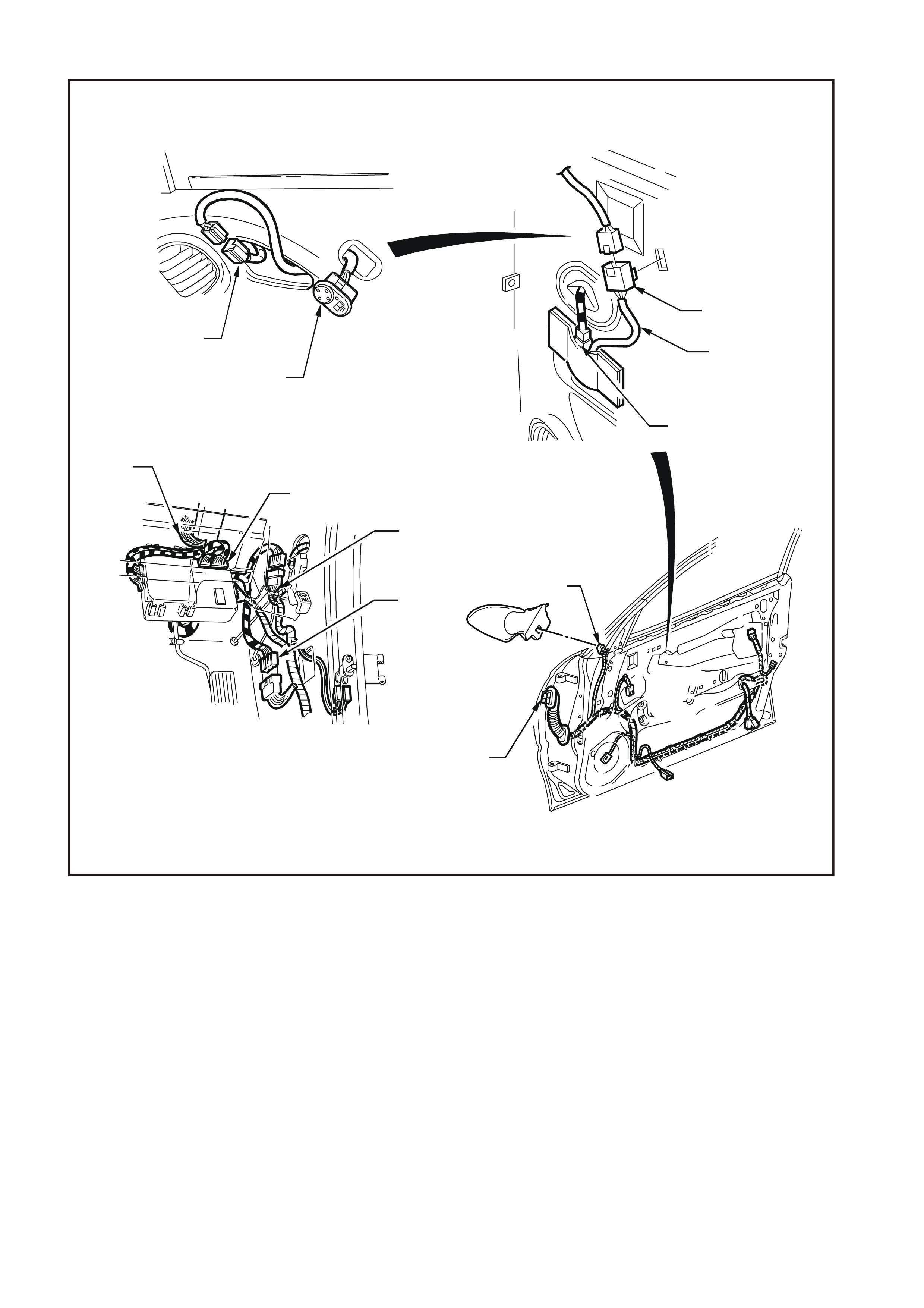
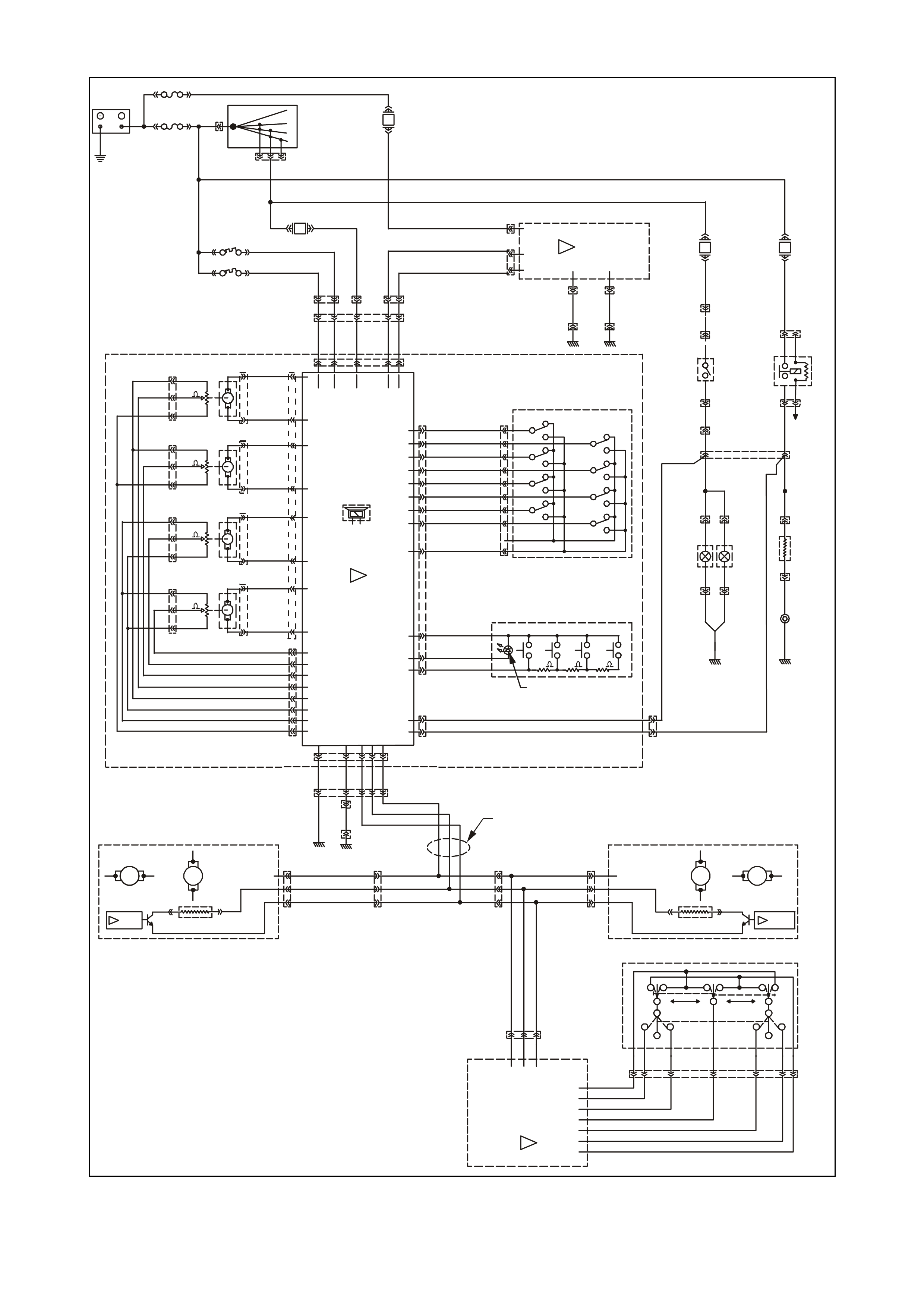
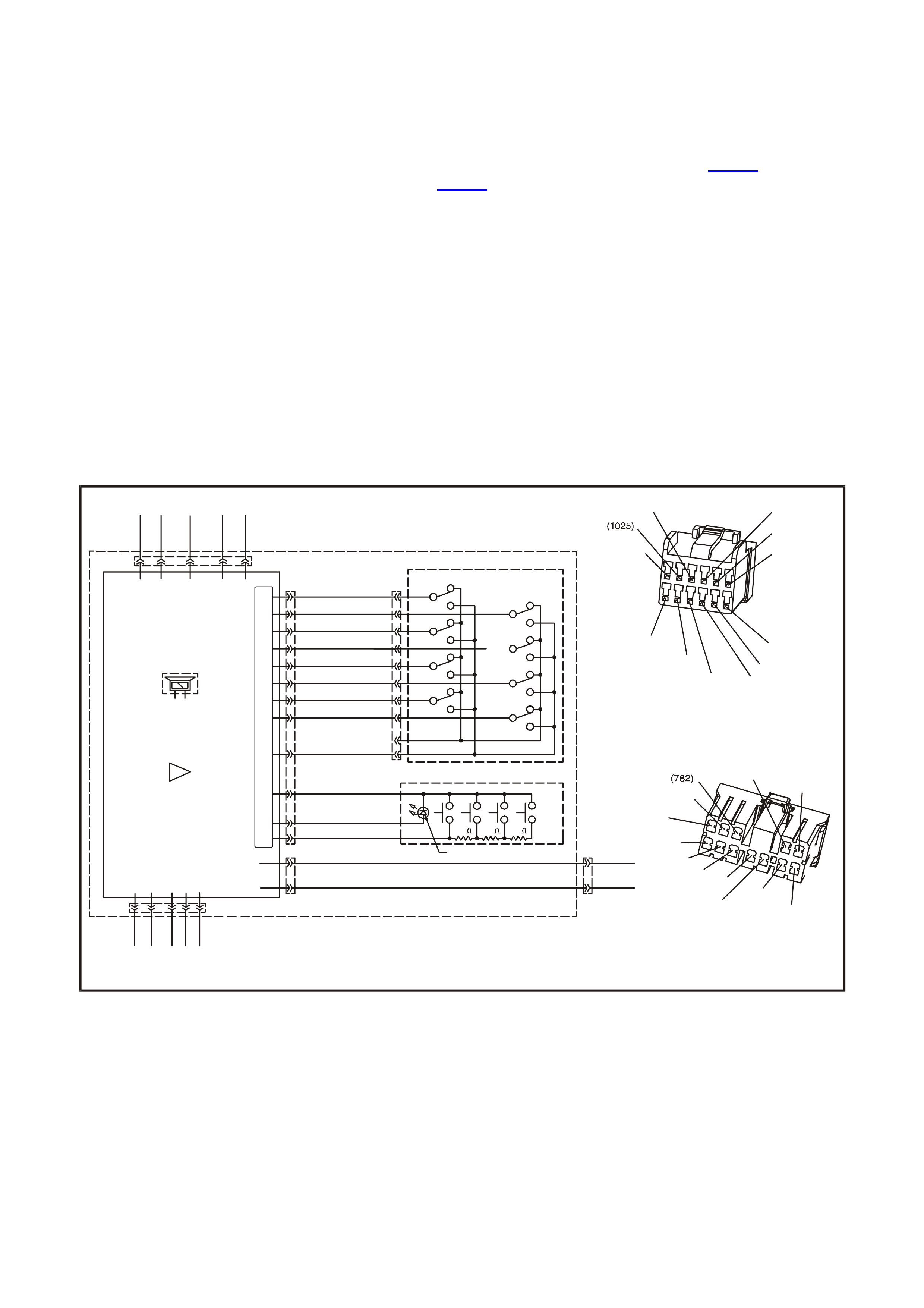
Four electrical connectors are located on the seat control module. The location of each connector is shown in Fig.
1A7-3 and circuit information is shown in Fig. 1A7-6. The seat control module connectors are:
• the memory and position connector YB225,
• the power connector YB227,
• the drive motor connector YB228, and
• the drive motor potentiometer connector YB229.
The memory and position connector YB225 connects the eight-way seat position switch to the seat control module.
Whenever a switch position is selected on the eight-way seat position switch, an earth is applied to the appropriate
input terminal to indicate to the seat control module that a change in seat position is required.
System power and earth as well as the priority key, reverse gear and heated window control signals are all applied
to the seat control module via the power connector YB227. The 12 signals on this connector are:
• The 12 V on circuit 540, which supplies the power for the seat drive motors.
• The 12 V on circuit 641, which supplies the power for the seat control module.
• The 12 V on circuit 139, which indicates the status of the ignition switch to the seat control module.
• The Priority 1 (circuit 782) and Priority 2 (circuit 783) signals, which indicate to the seat control module which
priority key has been used to open the vehicle. This is used to set the seat and mirrors to the position required by
the priority key.
• The Reverse signal on circuit 24, which indicates to the seat control module that the reverse gear has been
selected. This is used to dip the mirror on the passenger’s side of the vehicle.
• The Heated Rear Window signal on circuit 192, which controls the application of the supply voltage to the
external mirrors.
• The mirror serial data bus comprises three circuits; a data line (circuit 925), a 12 V supply line (circuit 929) and
an earth line (circuit 920).
• The earth for the seat drive motors is provided by circuit 156.
• The earth for the seat control module is provided by circuit 151.
The drive motor connector YB228 provides the power and earth circuits for each of the four seat drive motors.
The drive motor potentiometer connector YB229 provides the power and earth circuits for the potentiometers as
well as the seat drive motor position signal from the wiper of each potentiometer.
DIAGNOSTIC READOUT
The green LED located on the side of the driver’s seat is used to indicate the seat mode of operation as well as to
read out the various diagnostic trouble codes stored within the seat control module for fault diagnosis purposes.
The following table details the indications given by the LED in normal operation. For details on the various
diagnostic trouble codes, refer to 3.3 DIAGNOSTIC TROUBLE CODES in this Section.
MANUAL CONTROLS
The external rear vision mirrors can be controlled manually from the interior of the vehicle by the mirror switch
mounted in the driver's side front door pull handle. For further details, refer to Section 12H ELECTRICA LLY
ADJUSTABLE REAR VISION MIRRORS of the VT Series I Service Information.
An eight-way seat position switch is fitted to the outside of each seat frame. The horizontal switch provides
independent control of front and rear height (up and down movement) and fore/aft movement of seat, while the
vertical switch controls the seat backrest recliner angle.
During manual seat adjustment, the seat control module monitors the position of each motor axis and will shut down
the drive motor just before reaching the end of the track, even if the eight-way seat position switch is held on.
LED STATUS INDICATION
One flash. Priority 1 detected.
Two flashes. Priority 2 detected.
Three flashes when ignition set from
IGN to OFF. Diagnostic trouble code logged.
Steady illumination. System in awake mode.
Extinguished. System in sleep mode.
9
234
5
8
6
7
1
10
11
12
13
14
15
17
16
18
19
20
21
,
WH1A7003
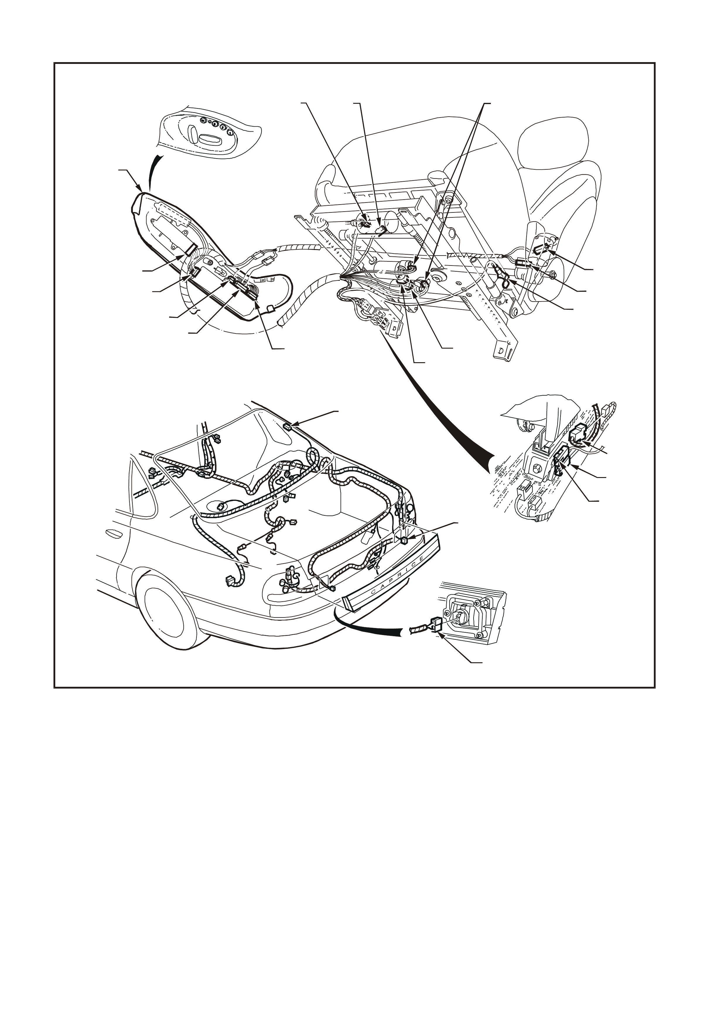
Figure 1A7-3
1. YB235 – Fore/Aft Drive Motor
Potentiometer Connector 8. YB221 – Rear Up/Down Drive
Motor Connector 15. Seat Lower Side Cover
2. YB223 – Fore/Aft Drive Motor
Connector 9. YB224 – Front Up/Down Drive
Motor Connector 16. YB226 – Power Seat Harness
Connector
3. YB235 – Front Up/Down Drive
Motor Potentiometer Connector 10. YB227 – Seat Control Module
Power Connector 17. Seat Belt Pre-tensioner Connector
4. YB235 – Rear Up/Down Drive
Motor Potentiometer Connector 11. YB228 – Seat Control Module Drive
Motor Connector 18. Side Air Bag Module Connector
5. YB222 – Recliner Up/Down Drive
Motor Connector 12. YB229 – Seat Control Module Drive
Motor Potentiometer Connector 19. YR53 – Left-hand Back-up Tail
Lamp Connector
6. YB236 – Recliner Drive Motor
Potentiometer Connector 13. YB225 – Seat Control Module
Memory and Position Connector 20. YR53 – Right-hand Back-up Tail
Lamp Connector
7. Seat Belt Pre-tensioner Connector 14. YB220 – Eight-way Seat Position
Switch Connector 21. YR1 – Heated Rear Window
Connector
WH1A7004
5
6
7
10
11
1
2
3
49
8
Figure 1A7-4
1. YB176 – BCM Connector (4)
2. YB174 – BCM Connector (2)
3. YB39 – Body Harness Connector
4. YB74 – Body Harness Connector
5. YB61 – Mirror Switch Connector
6. Mirror Switch Module (attached to
cable)
7. YB238 – Mirror Switch Module
Connector
8. YB76 – Right-hand Front D oor Harness
Connector (Left-hand is YB77)
9. YB237 – Right-hand Mirror
Connector (Left-hand is YB239)
10. YB61 – Mirror Switch Connector
11. Mirror Switch
WH1A7005
4567
8
9
10
A
11
12
A
1
2
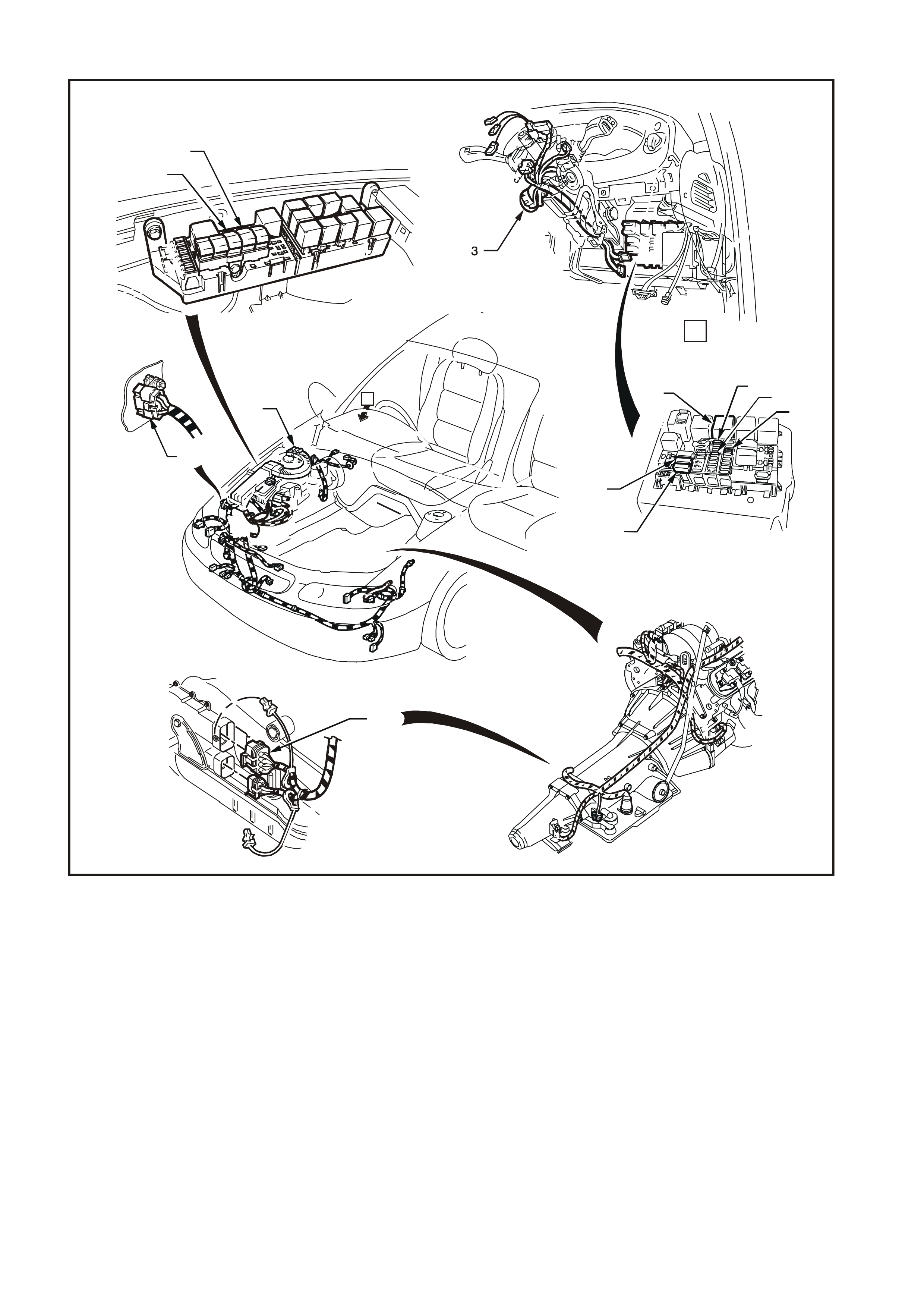
Figure 1A7-5
1. Fusible Link FS
2. Fusible Link FJ
3. YB44 – Ignition Switch Connector
4. Heated Rear Window Relay
(Connector YB41)
5. Fuse F12
6. Fuse F15
7. Fuse F22
8. Circuit Breaker F3
9. Circuit Breaker F2
10. YB35 – Neutral Start and Back-up
Switch Connector
11. YE114 – Earth Location E3 Connector
12. YE112 – Engine Connector (3)
85
(24)
YB41
ACC
YB227
3
YB220
F2
YR53
(641)
F31
YR1
(1027)
5
(177)
YB176
G
G/GY
(614)
(1029)
B/Y
Y
RECLINE UP
FS
AFT
YB44
YR53
YB222
(1023)
Y/P
YB228
(190)
BLU/R
12V
MOTOR 3
E IGHT - WAY SE AT PO SIT IO N S W ITCH
(185)
(155)
SPEAKER
M2
YE114
DIAGNOSTIC
LED
ELECTRONIC
GROUND
(179)
(189)
BACK-UP
SWITCH
O/B
F12
LOC. E6/E7
(40)
(156)
SEAT
CONTROL MODULE
LOC. E1
(2H)
YB41
(564)
B
GY
O/W
B
BODY CONTROL
MODULE
YB35
86
(156)
(783)
5015a
YE112
R/O
FRT UP
F3
(740)(139)
YB221
(1024)
YE114
BR/BLU
(621)
BACK-UP
LAMP
Y/B
(1021)
RECLINE DN
RR UP
B/W
YR53
YB39
(LH)
ENGINE 12V BUS
RECLINE
DRIVER'S SEAT
B/BLU
PRIORITY 1
12V
V/R
MOTOR 1
RR UP/RR DN
YB227
LOC. E3
V
B/G
YB223
(567)
Y
+5V
W
M3
YB174
(566)
1
(1025)
(180)
YR53
YB224
F22
B/BLU
F15
(540)
FJ
(176)
(782)
R/B
BLU/R
B/G
BR
POSITION SIG 3.
(563)
Y/W
87
30
YR1
OFF/ON
LOCK
START
(192)
FWD/AFT
YB174
+5V
(565) 0V
BR
30
P
15
O/B
POWER
GROUND
LG
(RH)
(24)
(192)
FWD
MOTOR 4
B
FRT DN
YB44
LOC. E3
V
(181)
YB35
(1022)
BACK-UP
LAMP
(1040)
YB39
LOC. E9
P
YB225
(42)
PRIORITY 2
(1028)
IGN
12V
B
MOTOR 2
10
0V
DIP
YB176
R/G
POSITION SIG 1.
(560)
(1026)
R
POSITION SIG 4.
(561)
(178)
V/Y
(562) POSITION SIG 2.
G
O
W/P
R
HEATED
REAR
WINDOW
RELAY
YE112
G/Y
BLU
V/G
(3)
DN
UP/FRT FRT
MEMORY POSITION SWITCH
(151)
RR DN
M1
B/Y
YB226
YB229 YB226
YB235
YB235
YB235
YB236
6
PRIORITY 1
PRIORITY 2
12V
YB39
YB74
Y/BLU
B/W
B/O
B/Y
Y
R/G
V
BR/BLU
+12V
REVERSE
SIG
REAR
HEATED
WINDOW
SIG
SERIAL DATA
GND (MIRROR
SERIAL
DATA
BUS)
GND
GND
BATTERY
+
B/BLU
YE114
(151)
YB39
LOC. E6 LOC. E3
(156)
YB227
YB226
GY/R
W/P
R/O
G
GY
(925)
BR
(929)
V
(920)
MIRROR MOTORS
GND
YB61
R
GY
BLU
VERTICAL
GND
MSDB
(920)
YB76
BR
BR
V
V
+12V
GY
(911)
MIRROR HEA TER
(929)
GY
MSDB
LR
B/R
B
SERIAL DATA
HV
SERIAL DATA
YB237
YB77
VERTICAL
(929)
V
LEFT - HAND MIRROR
BR
HORIZONTAL
LBLU
MIRROR HEATER
Y
(905)
MIRROR SW IT CH
W
12V
(929)
L
Y
G
H
(925)
(925)
+12V
V
S
YB238
(904)
(920)
GY
RIGHT - HAND M IRROR
YB239 MIRROR MOTORS
P
HORIZONTAL
BR
B
(909)
(908)
GND
(920)
N
MIRROR SWITCH
MODULE
E
WH1A7006
330
10K
10K
10K
10K
330 330
MIRROR
SERIAL
DATA
BUS
(
192
)
(24)
LG
V/R
Figure 1A7-6

2. SERVICE OPERATIONS
For service operations not covered in this Section refer to Section 1A7 SEAT & SEAT BELT ASSEMBLIES of the
VT Series I Service Information, which should be read in conjunction with Section 1A7 SEAT & SEAT BELT
ASSEMBLIES of the VT Series II Service Information.
2.1 SEAT CONTROL MODULE
REMOVE
1. There are two screws securing the lower side
cover to the seat; one is acces sed f rom the side
of the cover by removing the s cr ew cap f r om the
centre of the cover, and the other is accessed
from beneath the front of the seat. Move the
seat fully forward then remove both screws.
2. Carefully pull the lower side cover from the seat.
3. Remove the three screws securing the seat
control module cover to the seat lower side
cover.
4. Disconnect the four electrical connectors
(YB225, YB227, YB228 and YB229) from the
seat control module, refer to Fig. 1A7-3.
5. Remove the four screws securing the seat
control m odule to the s eat lower s ide c over, and
remove the module.
REINSTALL
Installation is the reverse of the rem oval proc edure,
noting the following.
1. After installation, carry out the drive motor
potentiometer calibration, refer to 2.7 DRIVE
MOTOR POTENTIOMETER CALIBRATION in
this Section.
Techline
Techline
Techline
Techline

2.2 MEMORY POSITION SWITCH
REMOVE
1. There are two screws securing the lower side
cover to the seat; one is acces sed f rom the side
of the cover by removing the s cr ew cap f r om the
centre of the cover, and the other is accessed
from beneath the front of the seat. Move the
seat fully forward then remove both screws.
2. Carefully pull the lower side cover from the seat.
3. Remove the two screws securing the memory
position switch cover to the seat lower side
cover.
4. Disconnect the electrical connector YB225 from
the memory seat control module, refer to Fig.
1A7-3.
5. Disconnect the electrical connector YB220 from
the eight-way seat position switch, refer to Fig.
1A7-3.
6. Remove the memory position switch, complete
with wiring harness.
REINSTALL
Installation is the reverse of the removal procedure.

2.3 EIGHT-WAY SEAT POSITION SWITCH
REMOVE
1. Pull the two knobs from the eight-way seat
position switch.
2. There are two screws securing the lower side
cover to the seat; one is acces sed f rom the side
of the cover by removing the s cr ew cap f r om the
centre of the cover, and the other is accessed
from beneath the front of the seat. Move the
seat fully forward then remove both screws.
3. Carefully pull the lower side cover from the seat.
4. Remove the three screws securing the eight-
way seat position switch cover to the seat lower
side cover.
5. Disconnect the electrical connector YB220 from
the eight-way seat position switch, refer to Fig.
1A7-3.
6. Remove the two screws securing the eight-way
seat position switch to the s eat lower s ide cover ,
and manoeuvre the switch out.
REINSTALL
Installation is the reverse of the removal procedure.

2.4 DRIVE MOTOR
REMOVE
The removal procedure is as follows:
• For the lift motors, refer to Sect io n 1A7 SEAT &
SEAT BELT ASSEMBLIES of the VT Series I
Service Information. Note that the drive motor
and potentiometer are replaced together as an
assembly.
• For the fore/aft drive motor, refer to Section
1A7 SEAT & SEAT BELT ASSEM BLIES of the
VT Series I Service Information. Note that the
drive motor and potentiometer are replaced
together as an assembly.
• For the backrest recliner drive motor, remove
the motor and potentiometer together as
detailed in Section 1A7 SEAT & SEAT BELT
ASSEMBLIES of the VT Series I Service
Information. Press in the two plastic tabs
securing the potentiometer to the drive motor
and separate the potentiometer from the motor.
REINSTALL
The installation procedure is the same as for the
appropriate drive motor of the VT Series II. Ref er to
Section 1A7 SEAT & SEAT BELT ASSEMBLIES
of the VT Series I Service Information, noting the
following.
1. After installation, carry out the drive motor
potentiometer calibration, refer to 2.7 DRIVE
MOTOR POTENTIOMETER CALIBRATION in
this Section.

2.5 DRIVE MOTOR POTENTIOMETER
REMOVE
The removal procedure is as follows:
• For the lift motor potentiometer, replace the
appropriate lift motor and potentiometer as an
assembly. Refer to 2.4 DRIVE MOTOR in this
Section.
• For the fore/aft drive motor potentiometer,
replace the fore/aft motor and potentiometer as
an assembly. Refer to 2.4 DRIVE MOTOR in
this Section.
• For the backrest recliner drive motor
potentiometer, remove the recliner motor and
separate the potentiometer from the motor as
detailed in 2.4 DRIVE MOTOR in this Section.
REINSTALL
Installation is the reverse of the rem oval proc edure,
noting the following.
1. After installation, carry out the drive motor
potentiometer calibration, refer to 2.7 DRIVE
MOTOR POTENTIOMETER CALIBRATION in
this Section.
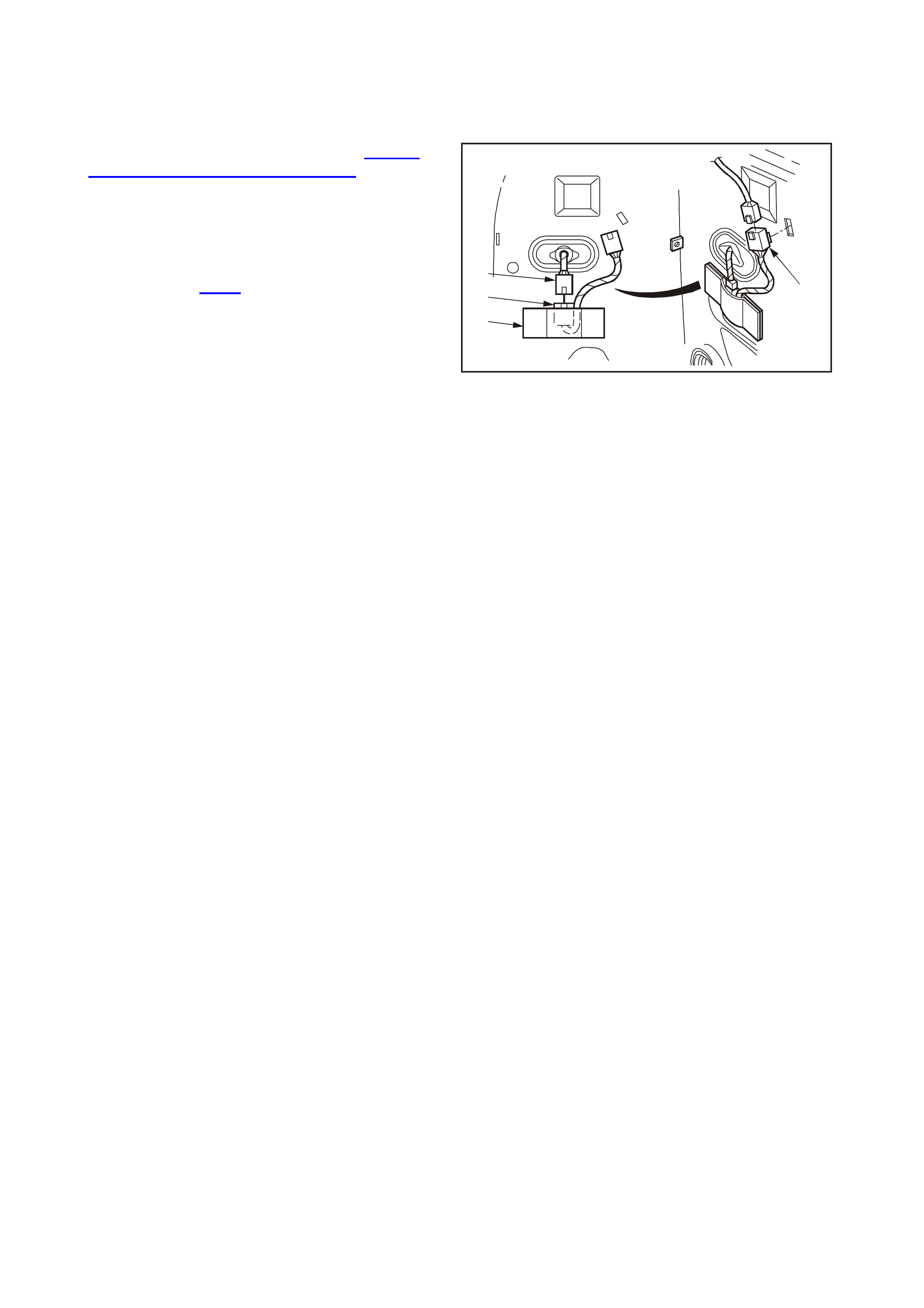
2.6 MIRROR SWITCH MODULE
REMOVE
1. Remove the driver’s door trim, refer to Section
1A5 FRONT AND REAR DOORS of this
Service Information CD.
2. Unclip the mirror switch connector YB61 (1)
from the door inner panel.
3. Disconnect the electrical connectors YB61 (1)
and YB238 (2) from the mirror switch module
(3), refer to Fig. 1A7-4.
4. Remove the mirror switch module from the
insulating pouch (4).
WH1A7011
2
3
4
1
Figure 1A7-7
REINSTALL
Installation is the reverse of the removal procedure.

2.7 DRIVE MOTOR POTENTIOMETER CALIBRATION
1. The drive motor potentiometer calibration
procedure must be carried out whenever any of
the following have been replaced:
• seat control module,
• a seat drive motor, or
• a drive motor potentiometer.
2. To access the diagnostic function, press and
hold the mirror dip button on the side of the
driver’s seat, while turning the ignition switch
from the OFF position to the IGN position three
time s in 6 seconds, leaving the ignition switch in
the IGN position.
NOTE: Do not turn the ignition switch too rapidly.
The switch must be in the OFF and IGN positions
long enough for the system to register the actual
position.
3. To enter the Drive Motor Potentiometer
Calibration diagnostic mode, press and hold
memory button 2 until a chime is heard, then
press and hold memory button 3. Successful
entry is indicated by a repetitive chime at a 2
second interval.
4. Using the eight-way seat position switch on the
side of the driver’s seat, move the seat fully
forward to the mechanical stop, releasing the
switch as soon as the stop is reached. It is
important that the switch is not held in the on
position after the mechanical stop is reached.
Move the seat slightly rearwards with the eight-
way switch, then move it f ully forward to the stop
again, releasing the switch at the stop. Repeat
this procedure for:
• the rearward direction of seat travel,
• the seat backrest fully forward and fully
reclined positions,
• the seat front fully up and fully down
positions, and
• the seat back fully up and fully down
positions.
5. Using the eight-way seat position switch, move
all four dr ive motors towards the m iddle pos ition
(approximately 3 seconds of travel).
6. Pr ess and hold the m irror dip button on the side
of the driver’s seat for approximately 2 seconds
to enter the calibration details. A multi-tone
chime confirms that the new calibration data has
been successfully stored.
7. Turn the ignition switch to the OFF position to
exit the Drive Motor Potentiometer Calibration
mode.
8. To verify the calibration settings, use the eight-
way seat position switch to move the seat fully
forward to the end of travel and release the
switch when the m otor stops . Operate the eight-
way switch in the same direction and hold for 2
seconds. The seat should move one step
beyond the initial stopping point. Repeat this
procedure for the remaining seat drive motors.
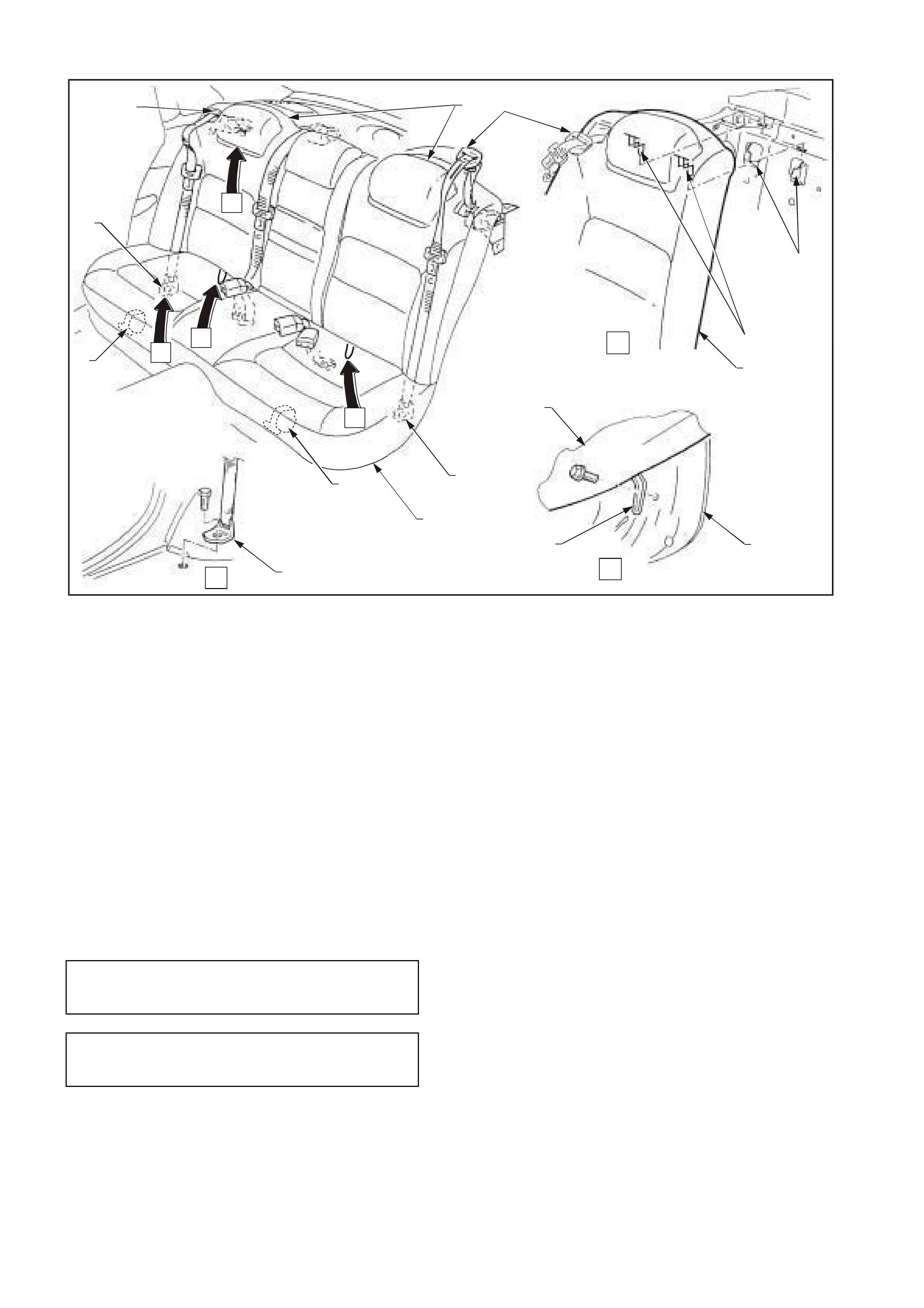
2.8 REAR SEAT CUSHION AND SEAT BACK ASSEMBLIES
REMOVE
1. Lift front edge of rear seat cushion slightly to
gain access to rear seat cushion release
handles. Refer to Fig. 1A7-9.
2. From either the left or right-hand side of the
seat, pull release handles downwards towards
the floor, while at the sam e time lif ting the front
of the rear seat cushion until the lock
mechanism is released.
3. Repeat Step 2 for the oppos ite side of the s eat
and remove the rear seat cushion from the
vehicle.
4. Remove the bolts secur ing the lower outer seat
belt anchors to the floor pan on the left and
right-side.
5. Pull forward and lower the rear seat centre
back.
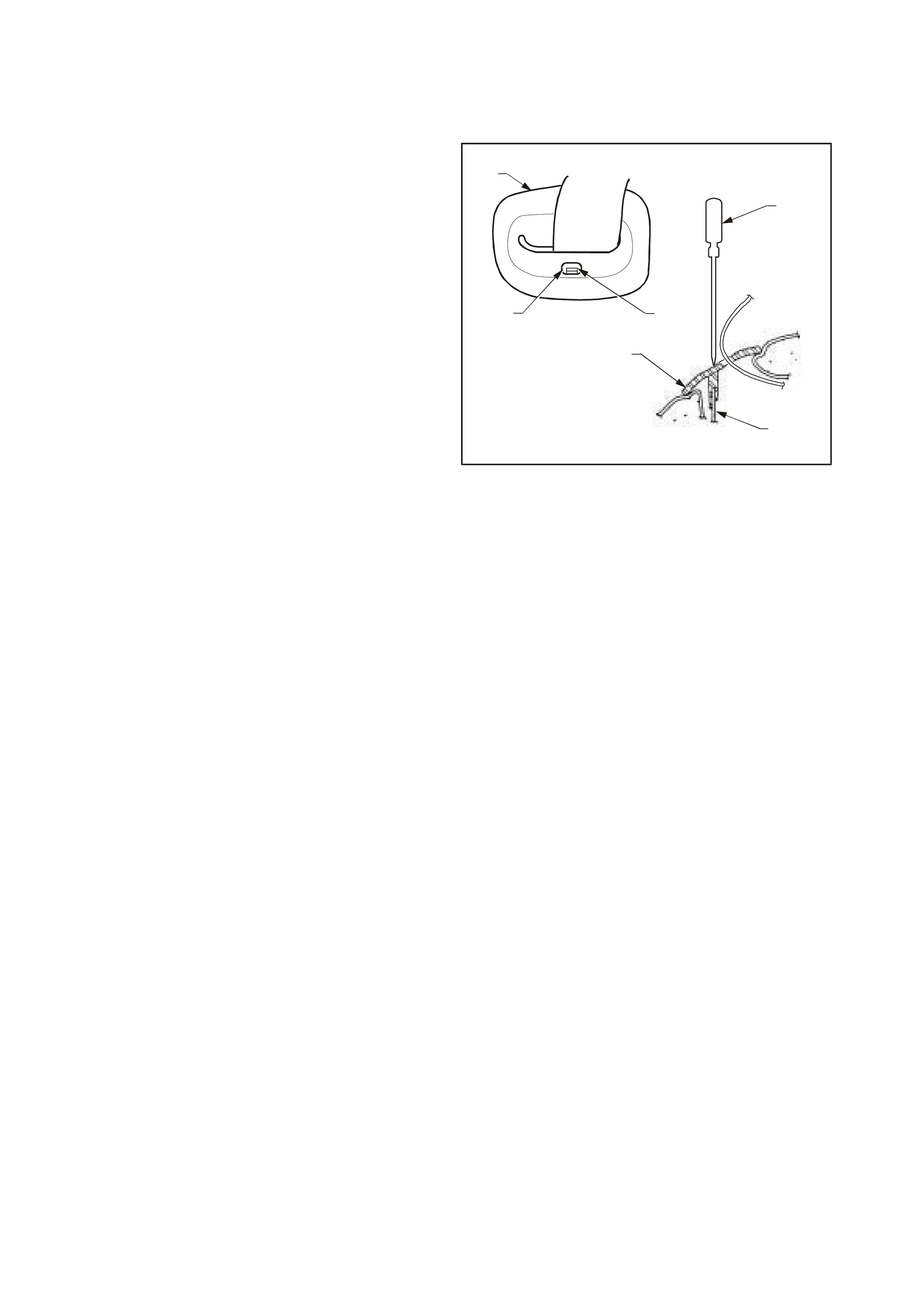
6. Remove the seat belt escutcheon (1) from the
left and right upper seat belt mounting bracket
(2) by inserting a suitable flat-blade sc rewdriver
(3) through the access hole (4) to disengage
the escutcheon retaining tang (5) f rom the seat
belt mounting bracket.
WH1A7015
1
1
2
3
45
Figure 1A7-8
7. Remove the bolts securing the left and right
seat back assemblies to the rear floorpan.
Refer to Fig 1A7-9.
8. Lift left and right seat back assemblies upwards
to disengage seat back hooks from retaining
brackets located on rear compartment front
panel.
9. Push seat belt, seat belt escutcheon and lower
seat belt anchor through the hole in the lef t and
right seat back assembly.
10. Remove the seat back assemblies from the
vehicle.
WH1A7013
3
4
7
6
4
4
59
2
12
8
1
2
3
C
C
A
B
AC
B
Figure 1A7-9
1. Seat cushion release handle
2. Lower outer seat belt anchor
3. Seat belt escutcheon
4. Seat back
5. Lower seat back mount
6. Seat back mounting hook
7. Seat back retaining bracket
8. Seat cushion
9. Floor pan
REINSTALL
Installation is the reverse of removal procedure,
noting the following:
1. Ensure that the threads of the lower outer seat
belt anchor bolts are adequately sealed with a
non-hardening sealer to Holden Specification
HN 1005 or HN 1044.
2. Ensure that all seat belt bolts are hand
tightened a minim um of five turns before using
tools.
3. Tighten all fasteners to the correct torque
specification.
SEAT BACK ASSEMBLY TO
FLOOR PAN RETAINING BOLT
TORQUE SPECIFICATION 25 – 35 Nm
LOWER SEAT BELT ANCHOR
RETAI NI NG B O LT T ORQUE
SPECIFICATION 35 – 50 Nm
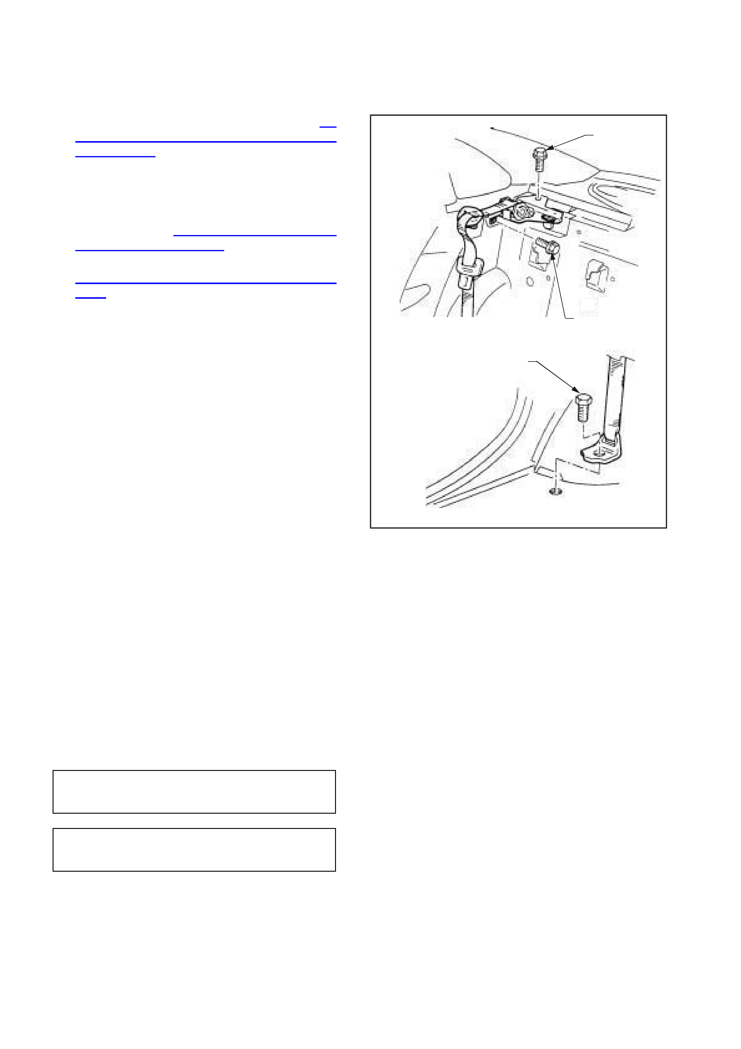
2.9 LEFT AND RIGHT-HAND REAR SEAT BELT RETRACTOR ASSEMBLIES
REMOVE
1. Remove the rear seat cushion. Refer to 2.8
REAR SEAT CUSHION AND BACK
ASSEMBLIES in this Section.
2. Remove the bolt (1) securing the lower outer
seat belt anchor to the f loor pan on the left and
right-hand side.
3. Remove the left and right-hand side seat
backs. Refer to 2.8 REAR SEAT CUSHION
AND BACK ASSEMBLIES in this Section.
4. Remove the rear parcel shelf trim. Refer to
Section 1A8 HEADLINING AND REAR END
TRIM in this Supplement.
5. Remove the two bolts (2) securing the rear seat
belt retractor assem blies to the vehic le body on
the left and right- hand side and remove the
assemblies.
WH1A7014
2
2
1
Figure 1A7-10
REINSTALL
Installation is the reverse of removal procedure,
noting the following:
1. Ensure that the threads of the lower outer seat
belt anchor bolts are adequately sealed with a
non-hardening sealer to Holden Specification
HN 1005 or HN 1044.
2. Ensure that all seat belt bolts are hand
tightened a minim um of five turns before using
tools.
3. Tighten all fasteners to the correct torque
specification.
LOWER OUTER SEAT BELT
ANCHOR RETA INING BOLT
TORQUE SPECIFICATION 35 – 50 Nm
SEAT BELT RETRACTOR
ASSEMBLY RETAINING BOLT
TORQUE SPECIFICATION 35 – 50 Nm
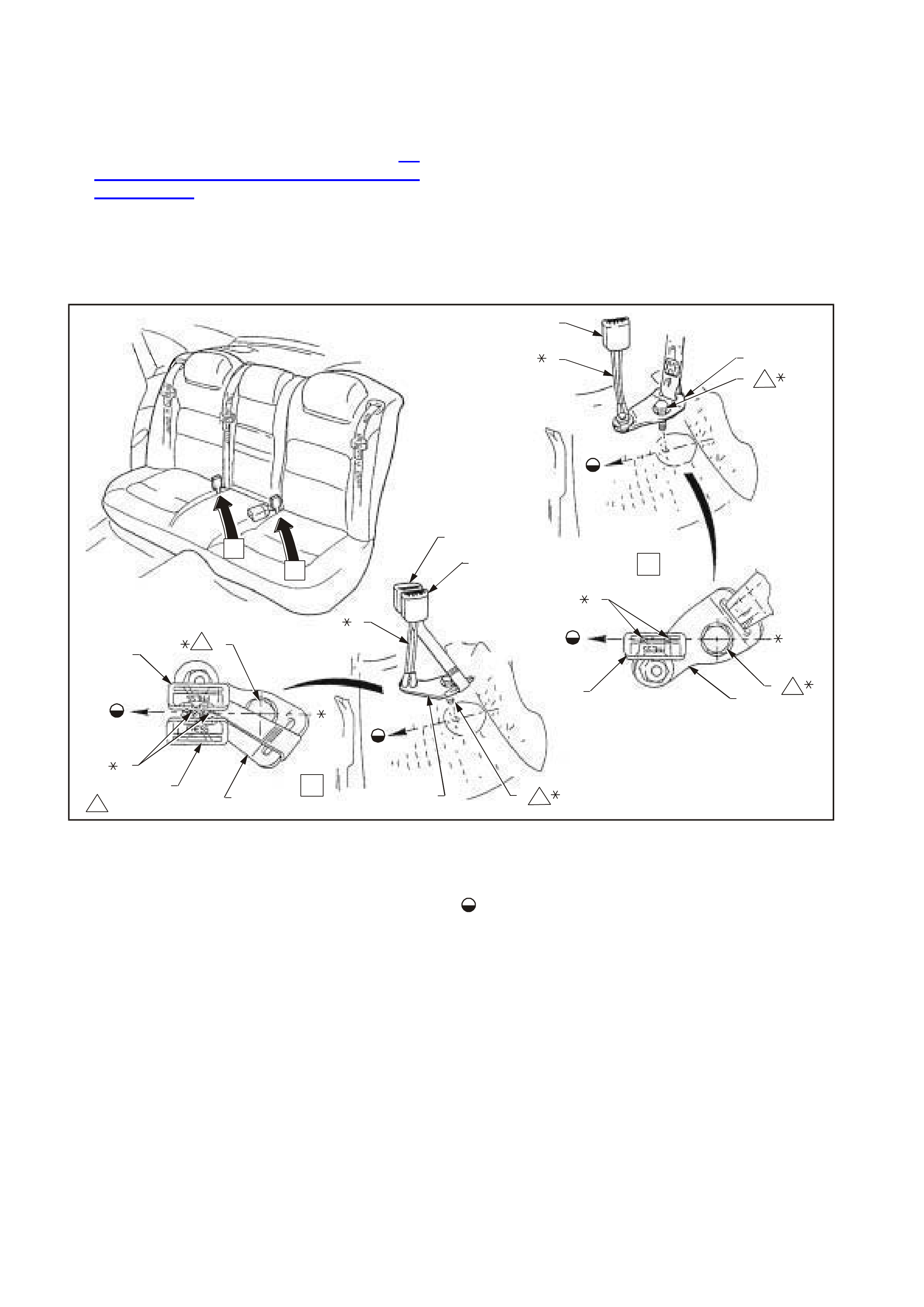
2.10 LEFT AND RIGHT-HAND REAR SEAT BELT BUCKLE
(STALK/WEB TYPE) ASSEMBLIES
REMOVE
1. Remove the rear seat cushion. Refer to 2.8
REAR SEAT CUSHION AND BACK
ASSEMBLIES in this Section.
2. Remove the bolt securing the left and
right-hand seat belt buckle anchor to the floor
pan.
3. Remove the seat belt buckle assembly from
the vehicle.
WH1A7016
6
78
9
9
7
68
3
2
5
14
3
5
1
2
4
B
A
A
B
1
1
1
1
1
35-50 Nm
Figure 1A7-11
1. Middle rear seat belt buckle
2. Left rear seat belt buckle
3. Left rear seat belt buckle anchor
4. Left rear seat belt buckle anchor bolt
5. Left rear seat belt buckle cable stalks
7. Right rear seat belt buckle
8. Right rear seat belt buckle cable stalks
9. Right rear seat belt buckle anchor
10. Right rear seat belt buckle anchor bolt
Indicates front and centre line of vehicle
* Centre line of these components must be parallel to
centre line of vehicle

REINSTALL
Installation is the reverse of removal procedure,
noting the following:
1. Ensure that the threads of the seat belt anchor
bolts are adequately sealed with a
non-hardening sealer to Holden Specification
HN 1005 or HN 1044.
2. Ensure that all seat belt bolts are hand
tightened a minim um of five turns before using
tools.
3. Tighten all fasteners to the correct torque
specification.
SEAT BELT BUCKLE ANCHOR
RETAI NI NG B O LT T ORQUE
SPECIFICATION 35 – 50 Nm

3. DIAGNOSTICS
3.1 GENERAL DIAGNOSTIC INFORMATION
The coded flashing of the LED and the seat chimes are useful tools in the diagnosis of sy stem problems.
The diagnostic function of the seat control module has four individual diagnostic modes to assist in system fault
diagnosis and repair. These are:
• Vehicle Interface Test.
• Display Stored Diagnostic Trouble Codes.
• Diagnostic Switch Test.
• Drive Motor Potentiometer Calibration.
VEHICLE INTERFACE TEST
The Vehicle Interface Test is a comprehensive check of all components of the memory seat and mirror system. If a
fault is detected during this check the corresponding Diagnostic Trouble Code (DTC) is stored in memory . If the
check is completed successfully, DTC 12 (No Fault) is stored in memory.
DISPLAY STORED DIAGNOSTIC TROUBLE CODES
DTC stored in the seat control module can be read out in this mode.
DIAGNOSTIC SWITCH TEST
The Diagnostic Switch Test checks each switch and button used in the seat and mirror circuit. A separate chime is
generated for each component tested successfully.
DRIVE MOTOR POTENTIOMETER CALIBRATION
The drive motor potentiometer calibration mode is used to align a new seat control module, drive motor or motor
potentiometer to the existing seat assembly.

3.2 DIAGNOSTIC FUNCTION
To access the diagnostic function, press and hold the mirror dip button on the side of the driver’s seat, while turning
the ignition switch from the OFF position to the IGN position three times in 6 seconds, leaving the ignition switch in
the IGN position.
NOTE: Do not turn the ignition switch too rapidly. The switch must be in the OFF and IGN positions long enough for
the system to register the actual position.
The seat chime sounds a constant tone and the green LED on the side of the driver’s seat flashes rapidly to indicate
that the diagnostic function has been entered. Using the seat memory buttons, select the actual diagnostic mode
required as follows:
• To enter the Vehicle Interface Test diagnostic mode, press memory button 1 followed by memory button 3.
Successful entry is indicated by a repetitive chime.
• To display the stored Diagnostic Trouble Codes, press memory button 1 followed by memory button 1 again.
Successful entry is indicated by the LED flashing rapidly.
• To enter the Diagnostic Switch Test diagnostic mode, press memory button 3 followed by memory button 3
again. Successful entry is indicated by a different tone sounding when any button or switch is pressed.
• To enter the Drive Motor Potentiometer Calibration diagnostic mode, press memory button 2 followed by
memory button 3. Successful entry is indicated by a repetitive chime at a 2 second interval.
To exit the diagnostic function, set the ignition switch to the OFF position. If in the Vehicle Interface Test diagnostic
mode a timer controls the mode exit process after turning the ignition off.

3.3 DIAGNOSTIC TROUBLE CODES
During the Vehicle Interface Test, the seat control module communicates with the mirrors and the mirror switch
module over the mirror serial data bus. The seat control module polls each component on the bus individually, and
each component responds to the poll with a unique message. Loss of communication with any of these components
will cause a DTC to be set.
DTC are stored in the seat control module as two-digit codes, with each digit being a number from 1 to 5. If a DTC
is present in the seat control module, other than DTC 12, the green LED on the side if the driver’s seat will flash
three times as the ignition is turned from IGN to OFF.
Upon entering the Display Stored Diagnostic Trouble Codes mode, the green LED provides the diagnostic readout
as follows:
• Flashes rapidly to indicate that a DTC is about to be displayed.
• Extinguishes briefly before flashing the ten’s digit.
• Extinguishes briefly before flashing the unit’s digit.
• Flashes rapidly to indicate that the next DTC is about to be displayed.
The DTC are displayed sequentially down the list and repeated until the ignition is switched off, or the diagnostic
mode times out after 1 minute. DTC are cleared by turning the ignition off.
The following table details the complete list of DTC numbers, the corresponding fault description and proposed
corrective action.
DTC DESCRIPTION CORRECTIVE ACTION
11 Not used. —
12 No faults. None required.
13 Not used. —
14 Vehicle Interface Test not completed. Repeat the Vehicle Interface Test.
15 Mirror bus shorted to earth. Go to the Mirror Bus Short Circuit Test.
21 Mirror bus shorted to 12 V. Go to the Mirror Bus Short Circuit Test.
22 No response received from seat control module. Replace the seat control module.
23 No response received from mirror control switch. Faulty wiring to the mirror switch or faulty seat control
module. Go to the Mirror Bus Wiring Test.
24 No response received from right mirror. Faulty wiring to the right-hand mirror or faulty mirror.
Go to the Mirror Bus Wiring Test.
25 No response received from left mirror. Faulty wiring to the left-hand mirror or faulty mirror.
Go to the Mirror Bus Wiring Test.
31 No response received from both mirrors. Faulty wiring to both mirrors or faulty mirrors. Go to
the Mirror Bus Wiring Test.
32 No response received from right mirror and mirror
control switch. Faulty wiring to the right-hand mirror and mirror
control switch, or faulty mirror and mirror control
switch. Go to the Mirror Bus Wiring Test.
33 No response received from left mirror and mirror
control switch. Faulty wiring to the left-hand mirror and mirror control
switch, or faulty mirror and mirror control switch. Go
to the Mirror Bus Wiring Test.
34 No response received from both mirrors and mirror
control switch. Go to the Mirror Bus Wiring Test.
35 Position error right mirror. Faulty right-hand mirror or obstructed mirror glass.
41 Position error left mirror. Faulty left-hand mirror or obstructed mirror glass.
42 Mirror bus power less than 2 V at seat control
module. No power switched from the seat control module to
the mirrors. Replace the seat control module.
43 Mirror bus power less than 8 V at seat control
module. Low voltage on mirror power bus. Go to the Mirror
Bus Wiring Test.
44 – 45 Not used. —
51 – 55 Not used. —

3.4 PRELIMINARY SYSTEM DIAGNOSIS
When investigating any complaint of a memory seat and mirror system problem or malfunction, always begin
diagnosis with a Vehicle Interface Test, refer to 3.6 DIAGNOSTIC PROCEDURES in this Section.
If the Vehicle Interface Test does not find a likely source of the fault, the Diagnostic Circuit Check should then be
carried out.

3.5 DIAGNOSING FAULTS WHICH DO NOT SET A DTC
STALLED MOTOR
If a seat motor has been energised and the corresponding potentiometer (position sensor) does not change state,
then the seat control module determines that the motor has stalled, and removes electrical power from the motor
and sets an internal motor-stalled flag. A DTC is not logged for this fault condition.
To reset the motor-stalled flag and apply power to the motor, push the eight-way seat position switch in the
appropriate direction for 2 seconds.
To check for correct operation of the seat motors, use the Drive Motor and Motor Potentiometer Test. Refer to
3.6 DIAGNOSTIC PROCEDURES in this Section.
SHORTED SWITCH CONTACT
If the seat control module detects that the eight-way seat position switch has been in an active position for too long,
a shorted switch contact condition is declared by the module. A DTC is not logged for this fault condition.
The maximum continuous operating time for the seat fore/aft and lift motors is 25 seconds before a shorted switch
contact condition is declared. For the seat backrest recliner motor, this is extended to a maximum of 50 seconds.
To check for correct operation of the eight-way seat position switch, use the Diagnostic Switch Test. Refer to
3.6 DIAGNOSTIC PROCEDURES in this Section.
3.6 DIAGNOSTIC PROCEDURES
INTRODUCTION
The following charts are designed to provide fast and efficient fault location within the memory seat and mirror
system. Always begin diagnosis with the Vehicle Interface Test which verifies that all the components of the system
are functioning correctly. If the Vehicle Interface Test detects a fault, a DTC will set to assist the fault finding
process.
If the Vehicle Interface Test does not find a likely source of the fault, the Diagnostic Circuit Check should then be
carried out.
Some of the diagnostic procedures require the use of both priority keys.
When carry ing out wiring checks as directed by the diagnostic charts, rather than probe terminals and connectors
with incorrect sized multimeter connections, use the adaptors contained in the test adaptor kit KM-609. This will
prevent any possibility of spreading or damaging wiring harness terminals which may later cause a system
intermittent failure.
The location of the seat control module and connectors is shown in Fig. 1A7-12.
WH1A7007
123 45678
Figure 1A7-12
1. Memory Position Switch 4. YB225 Seat Control Module
Memory and Position Connector 7. YB228 Seat Control Module Drive
Motor Connector
2. Eight-way Seat Position Switch 5. Seat Control Module 8. YB227 Seat Control Module Power
Connector
3. YB220 Eight-way Seat Position
Switch Connector 6. YB229 Seat Control Module Drive
Motor Potentiometer Connector

VEHICLE INTERFACE TEST
INTRODUCTION
This test provides a comprehensive check of all components of the memory seat and mirror system. The location of
the seat control module connectors is shown in Fig. 1A7-12. For circuit diagram and other connector information,
refer to Figs. 1A7-3 to 1A7-6.
TEST DESCRIPTION
The various steps in the Vehicle Interface Test verify the following functions:
Step 1 — Enters the Vehicle Interface Test mode.
Step 2 — Checks the reverse gear selection.
Step 3 — Isolates a reverse gear selection problem to a circuit wiring fault or a defective seat control module.
Step 4 — Checks the rear window demister and mirror heater selection.
Step 5 — Isolates a rear window demister and mirror heater selection problem to a circuit wiring fault or a defective
seat control module.
Step 6 — Checks for an intermittent fault in the ignition circuit.
Step 7 — Checks the correct identification of priority keys.
Step 8 — Checks the priority signal lines from the BCM.
Step 9 — Identifies that a DTC is stored, or successful completion of the test.
Step 10 — Checks the reverse signal application to the seat control module.
Step 11 — Checks the correct operation of the mirror heater circuits.
Step 12 — Identifies a single faulty mirror heater.
Step 13 — Checks the heated rear window signal at the input to the seat control module.
Step 14 — Checks the decoding of priority key signals.
VEHICLE INTERFACE TEST PROCEDURE
STEP ACTION VALUE YES NO
1 • Remove the lower side cover from the driver’s
seat to gain access to the seat control module,
which is required during this test.
• Press and hold the mirror dip button and turn
ignition switch from OFF to IGN three times within
6 seconds. Leave the ignition switch in the IGN
position.
• After a constant tone sounds, press and hold
memory button 1 until a chime sounds
(approximately 1 second).
• Press and hold memory button 3 for 1 second to
enter the Vehicle Interface Test mode.
• A repetitive chime sounds to indicate that the
Vehicle Interface Test has been successfully
entered.
• Did the repetitive chime change to an alternating
frequency (siren)?
Go to Step 10. Check fuse F15 and
circuit 139. If OK, go
to Step 2.
2 • Select reverse gear.
• Did the repetitive chime change tone? Go to Step 4. Go to Step 3.
3 • Ensure that the ignition switch is still in the IGN
position.
• Using a multimeter, measure the reverse gear
signal voltage on circuit 24 (Violet wire) at the
power connector YB227 while shifting between
reverse and park.
• Are the readings as specified?
Reverse =
12 V
Park = 0 V
Replace faulty seat
control module.
Refer to 2.1 SEAT
CONTROL
MODULE in this
Section.
Check circuit 24 and
repair as necessary.
4 • Set the rear window demister switch to on.
• Did the repetitive chime change tone? Go to Step 6. Go to Step 5.

VEHICLE INTERFACE TEST PROCEDURE (continued)
STEP ACTION VALUE YES NO
5 • Ensure that the ignition switch is still in the IGN
position.
• Using a multimeter, measure the rear window
demister signal voltage on circuit 192 (Brown/Blue
wire) at the power connector YB227 while
switching between off and on.
• Are the readings as specified?
On = 12 V
Off = 0 V Replace faulty seat
control module.
Refer to 2.1 SEAT
CONTROL
MODULE in this
Section.
Check circuit 192
and repair as
necessary.
6 • Turn the ignition switch to the OFF position and
remove t he k ey.
• Did the repetitive chime change tone?
Go to Step 7. Intermittent fault in
the ignition circuit.
Check circuit 139
and repair as
necessary.
7 • Press the door unlock button on Priority Key 1.
• Press the door unlock button on Priority Key 2.
• Did the repetitive chime change tone with Key 1 or
Key 2?
Go to Step 9. Go to Step 8.
8 • Insert Priority Key 1 in the ignition switch.
NOTE: Use adaptors from test adaptor kit KM-609 to
back probe the terminals of power connector YB227.
• Using a multimeter, measure the priority 1 signal
voltage on circuit 782 (Black/Yellow wire) and the
priority 2 signal voltage on circuit 783 (Yellow
wire) at the power connector YB227 while
switching the ignition between OFF and IGN.
• Repeat the measurement of both signals for the
Priority Key 2.
• Are the readings as specified?
4 V in OFF
0.6 V in IGN Replace faulty seat
control module.
Refer to 2.1 SEAT
CONTROL
MODULE in this
Section.
Check circuits 782
or 783 and repair as
necessary.
9 • Did a repeating tone of alternating frequency
sound? Go to Read
Diagnostic Trouble
Code in this Section.
A single burst of
three tones in
increasing frequency
indicates successful
test completion.
10 • Select reverse gear and press the mirror dip
button twice.
• Select park and again press the mirror dip button
twice.
• Did a chime sound for reverse gear but not for
park?
Got to Step 11. Go back to Step 3.
11 • Check that the external rear vision mirrors are
cold.
• Turn the ignition switch to the IGN position.
• Set the rear window demister switch to on.
• Did both mirrors get warm after 2 minutes?
Go to Step 14. Go to Step 12.
12 • Did only one of the two mirrors get warm? Go to Mirror Bus
Wiring Test in this
Section.
Go to Step 13.
13 • Ensure that the ignition switch is still in the IGN
position.
NOTE: Use adaptors from test adaptor kit KM-609 to
back probe the terminals of power connector YB227.
• Using a multimeter, measure the rear window
demister signal voltage on circuit 192 (Brown/Blue
wire) at the power connector YB227 while
switching between off and on.
• Are the readings as specified?
On = 12 V
Off = 0 V Go to Step 14. Check circuit 192
and repair as
necessary.
14 • Turn the ignition switch to the OFF position.
• Press the door unlock button on Priority Key 1 and
observe the seat LED.
• Press the door unlock button on Priority Key 2 and
observe the seat LED.
• Did the LED flash once for Priority Key 1 and twice
for Priority Key 2?
Go to Read
Diagnostic Trouble
Code in this Section.
Go back to Step 8.
WHEN ALL DIAGNOSIS AND REPAIRS ARE COM PLETED, VERIFY CORRECT OPERATION

READ DIAGNOSTIC TROUBLE CODE
INTRODUCTION
The DTC are read from the seat control module using the following procedure.
STEP ACTION VALUE YES NO
1 • Press and hold the mirror dip button and turn
ignition switch from OFF to IGN three times within
6 seconds. Leave the ignition switch in the IGN
position.
• After a constant tone sounds, press and hold
memory button 1 until a chime sounds.
• Press and hold memory button 1 again to enter
the Read Diagnostic Trouble Code diagnostic
mode.
• Observe the green LED on the side of the driver’s
seat. The LED will flash rapidly to indicate that
Read Diagnostic Trouble Code entry has been
successful. The LED will then flash the two digits
of the DTC, commencing with the ten’s digit.
• Did the LED display one or more DTC?
Go to Step 2. Repeat Step 1.
2 • Did the LED display DTC 12? No faults found.
End of diagnosis. Go to Step 3.
3 • Did the LED display DTC other than DTC 12? Refer to the
following diagnostic
chart.
—
W HE N ALL DIAGNOS IS AND RE PAIRS ARE COMPL ETED, VE RIFY CORRECT OPERATION
DTC DESCRIPTION CORRECTIVE ACTION
11 Not used. —
12 No faults. None required.
13 Not used. —
14 Vehicle Interface Test not completed. Repeat the Vehicle Interface Test.
15 Mirror bus shorted to earth. Go to the Mirror Bus Short Circuit Test.
21 Mirror bus shorted to 12 V. Go to the Mirror Bus Short Circuit Test.
22 No response received from seat control module. Replace the seat control module.
23 No response received from mirror control switch. Faulty wiring to the mirror switch or faulty seat control
module. Go to the Mirror Bus Wiring Test.
23 No response received from mirror control switch. Faulty wiring to the mirror switch or faulty seat control
module. Go to the Mirror Bus Wiring Test.
24 No response received from right mirror. Faulty wiring to the right-hand mirror or faulty mirror.
Go to the Mirror Bus Wiring Test.
25 No response received from left mirror. Faulty wiring to the left-hand mirror or faulty mirror.
Go to the Mirror Bus Wiring Test.
31 No response received from both mirrors. Faulty wiring to both mirrors or faulty mirrors. Go to
the Mirror Bus Wiring Test.
32 No response received from right mirror and mirror
control switch. Faulty wiring to the right-hand mirror and mirror
control switch, or faulty mirror and mirror control
switch. Go to the Mirror Bus Wiring Test.
33 No response received from left mirror and mirror
control switch. Faulty wiring to the left-hand mirror and mirror control
switch, or faulty mirror and mirror control switch. Go
to the Mirror Bus Wiring Test.
34 No response received from both mirrors and mirror
control switch. Go to the Mirror Bus Wiring Test.
35 Position error right mirror. Faulty right-hand mirror or obstructed mirror glass.
41 Position error left mirror. Faulty left-hand mirror or obstructed mirror glass.
42 Mirror bus power less than 2 V at seat control
module. No power switched from the seat control module to
the mirrors. Replace the seat control module.
43 Mirror bus power less than 8 V at seat control
module. Low voltage on mirror power bus. Go to the Mirror
Bus Wiring Test.
44 – 45 Not used. —
51 – 55 Not used. —

DIAGNOSTIC CIRCUIT CHECK
INTRODUCTION
The Diagnostic Circuit Check is a detailed system check which verifies that all the components of the system are
functioning correctly and that the seat control module is receiving priority signals from the BCM.
TEST DESCRIPTION
The various steps in the Diagnostic Circuit Check test the following functions:
Step 1 — Input power and circuit protection.
Step 2 — LED test.
Step 3 — Memory button chime function.
Step 4 — Enter diagnostic function successfully.
Steps 5 to 7 — Seat manual move function.
Steps 8 to 10 — Seat memory store and recall function.
Step 11 — Ignition switch disable function.
Steps 12 and 13 — Priority store and recall function.
Step 14 — Mirror manual move function.
Steps 15 to 17 — Mirror memory store and recall function.
Steps 18 and 19 — Priority read from ignition switch function.
Steps 20 to 24 — Mirror dip function.
Steps 25 and 26 — Mirror heater function.
Steps 27 to 29 — Sleep mode function.
DIAGNOSTIC CIRCUIT CHECK PROCEDURE
STEP ACTION VALUE YES NO
1 • Check battery voltage.
• Check circuit breakers F2 and F3, and fuse F15
on the fuse and relay panel located in the lower
dash panel.
• All OK?
Go to Step 2. Replace as
necessary.
Go to Step 2
2 • Turn ignition switch from OFF to IGN.
• Did the seat LED flash?
NOTE: LED flashes once for Priority Key 1 or twice
for Priority Key 2.
Go to Step 3. Go to LED Test in
this Section.
3 • Turn the ignition switch to OFF.
• Press memory buttons 1, 2 and 3 sequentially.
• Did a chime sound for each button pressed?
Go to Step 4. Go to Chime Test in
this Section.
4 • Press and hold the mirror dip button and turn
ignition switch from OFF to IGN three times within
6 seconds. Leave the ignition switch in the IGN
position.
• Did a constant tone sound?
Diagnostic function
operates correctly.
Go to Step 5.
Go to Diagnostic
Mode Test in this
Section.
5 • Turn the ignition switch to OFF and remove the
key.
• Using the eight-way seat position switch, move the
seat fully back, front down, rear down and
backrest fully back.
• Can the seat be moved by all four motors?
Go to Step 7. Go to Step 6.
6 • Is battery voltage above 10 V when driving
motors? Go to Manual Seat
Move Test in this
Section.
Charge or replace
battery, then go to
Step 7.
7 • Using the eight-way switch, move the seat fully
forward, front up, rear up and backrest fully
forward.
• Can the seat be moved to the end-points in both
directions by all four motors?
Seat manual move
function operates
correctly.
Go to Step 8.
Go to Manual Seat
Move Test in this
Section.

DIAGNOSTIC CIRCUIT CHECK PROCEDURE (continued)
STEP ACTION VALUE YES NO
8 • Using the eight-way switch, move the seat to the
middle position for all directions of travel.
• Press and hold memory button 2 for more than
2 seconds to store the seat position in memory set
2.
• Using the eight-way switch, move the seat to the
80% forward and down position.
• Press and hold memory button 1 for more than
2 seconds to store the seat position in memory set
1.
• Press and release memory button 2 within
1 second to recall memory set 2 position.
• Did all four motors move the seat to the middle
position?
Go to Step 9. Go to Drive Motor
and Motor
Potentiometer Test
in this Section.
9 • Using the eight-way switch, move the seat to the
80% back and up position.
• Press and hold memory button 3 for more than
2 seconds to store the seat position in memory set
3.
• Press and release memory button 1 within
1 second to recall memory set 1 position.
• Did all four motors move the seat to the 80%
forward and down position?
Go to Step 10. Go to Drive Motor
and Motor
Potentiometer Test
in this Section.
10 • Press and release memory button 3 within
1 second.
• Did all four motors move the seat to the 80% back
and up position as set in Step 9?
Seat memory store
and recall function
operates correctly.
Go to Step 11.
Go to Drive Motor
and Motor
Potentiometer Test
in this Section.
11 • Insert the key and turn ignition switch from OFF to
IGN.
• Press and release memory button 2 within
1 second to recall memory set 2 position.
• Did all four motors move the seat to the middle
position as set in Step 8?
Go to Vehicle
Interface Test in this
Section.
Ignition switch
disable function
operates correctly.
Go to Step 12.
12 • Turn the ignition switch to OFF and remove the
key.
• Press the door unlock button on Priority Key 1.
The seat may move at this point.
• Press and release memory button 1 within
1 second to recall memory set 1 position. The seat
will move to the 80% forward and down position.
• Press the door unlock button on Priority Key 2.
The seat can move at this point.
• Press and release memory button 2 within
1 second to recall memory set 2 position. The seat
will move to the middle position.
• Press the door unlock button on Priority Key 1.
• Did all four motors move the seat to the 80%
forward and down position, and did the seat LED
flash once?
Go to Step 13. Go to Vehicle
Interface Test in this
Section.
13 • Press the door unlock button on Priority Key 2.
• Did all four motors move the seat to the middle
position, and did the seat LED flash twice?
Go to Step 14. Go to Vehicle
Interface Test in this
Section.
14 • Insert the key and turn ignition switch from OFF to
IGN.
• Move both left and right rear vision mirrors through
all four directions using the mirror control switch.
• Can both mirrors be moved in all directions?
Go to Step 15. Go to Manual Mirror
Move Test in this
Section.

DIAGNOSTIC CIRCUIT CHECK PROCEDURE (continued)
STEP ACTION VALUE YES NO
15 • Using the mirror control switch, centre both
mirrors in the horizontal and vertical planes.
• Press and hold memory button 2 for more than
2 seconds to store the mirror position in memory
set 2.
• Using the mirror control switch, move both mirrors
to the up and out position.
• Press and hold memory button 1 for more than
2 seconds to store the mirror position in memory
set 1.
• Using the mirror control switch, move both mirrors
to the down and in position.
• Press and hold memory button 3 for more than
2 seconds to store the mirror position in memory
set 3.
• Press and release memory button 2 within
1 second to recall memory set 2 position.
• Did both mirrors move to the middle position?
Go to Step 16. Go to Mirror Recall
Test in this Section.
16 • Press and release memory button 1 within
1 second to recall memory set 1 position.
• Did both mirrors move to the up and out position?
Go to Step 17. Go to Mirror Recall
Test in this Section.
17 • Press and release memory button 3 within
1 second to recall memory set 3 position.
• Did both mirrors move to the down and in
position?
Go to Step 18. Go to Mirror Recall
Test in this Section.
18 • Press the door unlock button on Priority Key 1.
• Insert Priority Key 2 in the ignition and turn ignition
switch from OFF to IGN.
• Did the seat LED flash twice?
Go to Step 19. Go to Vehicle
Interface Test in this
Section.
19 • Turn the ignition switch OFF and remove the key.
• Press the door unlock button on Priority Key 2.
• Insert Priority Key 1 in the ignition and turn ignition
switch from OFF to IGN.
• Did the seat LED flash once?
Go to Step 20. Go to Vehicle
Interface Test in this
Section.
If no fault is found in
this test, then fault is
with the key or slip-
ring connection.
20 • Using the mirror control switch, move the
passenger’s rear vision mirror to a forward driving
position.
• Select reverse gear.
• Did the passenger’s mirror move to a dip position?
Go to Step 24. Go to Step 21.
21 • Press the mirror dip button on the side of the seat
twice. A chime w ill sound on pressing the button. If
the last chime had the lowest frequency , press the
mirror dip button again.
• Did a chime sound when the mirror dip button w as
pressed?
Go to Step 22. Go to Diagnostic
Switch Test in this
Section.
22 • Did the passenger’s mirror move to a dip position? Go to Step 24. Go to Step 23.
23 • Using the mirror control switch, move the
passenger’s rear vision mirror to another position.
• Select park.
• Did the passenger’s mirror return from a dip
position to the forward driving position?
Go to Step 25. Go to Vehicle
Interface Test in this
Section.
24 • Press the mirror dip button on the side of the seat.
• Did the passenger’s mirror return from a dip
position to the forward driving position, and did a
chime sound?
Go to Step 25. Go to Diagnostic
Switch Test in this
Section.

STEP ACTION VALUE YES NO
25 • Check that the ignition switch is in the IGN
position and the rear window demister is off.
• Are both rear vision mirrors still cool after
2 minutes?
Go to Step 26. Go to Mirror Heater
Test in this Section.
26 • Set the rear window demister switch to on.
• Did both mirrors get warm after 2 minutes? Go to Step 27. Go to Mirror Heater
Test in this Section.
27 • Turn the ignition switch to OFF and remove the
key. Do not operate any switches for 5 minutes.
• Did the seat LED extinguish after 5 minutes?
Go to Step 28. Go to Sleep Mode
Test in this Section.
28 • Can the mirrors be moved using the mirror switch
while the LED is extinguished? Go to Sleep Mode
Test in this Section. Go to Step 29.
29 • Can the seat be moved using the eight-way seat
position switch? End of diagnosis. Go to Sleep Mode
Test in this Section.
WHEN ALL DIAGNOSIS AND REPAIRS ARE COM PLETED, VERIFY CORRECT OPERATION
CHIME TEST
INTRODUCTION
This test verifies the correct operation of the chime circuit within the seat control module as well as the appropriate
voltage and earth circuits. The location of the seat control module connectors is shown in Fig. 1A7-12. For circuit
diagram and other connector information, refer to Fig. 1A7-13.
TEST DESCRIPTION
The various steps in the Chime Test verify the following functions:
Step 1 — Ensures that the Vehicle Interface Test is carried out eliminate other possible faults.
Step 2 — Checks the chime function for correct operation.
Step 3 — Checks the input voltage.
Step 4 — Checks the terminal retention of chime circuit connector pins.
Step 5 — Checks the chime function at the input to the seat control module.
Step 6 — Checks the voltage circuit protection.
Step 7 — Identifies presence of an intermittent fault.
Step 8 — Checks for a short between the mirror bus power and mirror bus earth circuits.
Step 9 — Isolates the fault to a circuit wiring problem or a defective seat control module.
YB227
YB220
(1027)
+12V
G
REVERSE
SIG
G/GY
(614)
(1029)
B/Y
YRECLINE UP
AFT
(1023)
HEATED REAR
WINDOW
SIG
Y/P
BLU/R
IGN.
12V
EIGHT-WAY SEAT POSITION SWITCH
SPEAKER
M2
DIAGNOSTIC
LED
SEAT CONTROL
MODULE
B
R/O
FRT UP
(1024)
SERIAL DATA
(621)
(1021)
RECLINE DN
RR UP
B/W
YB227
12V
YB227
M3
(1025)
GND
(613)
(24)
(192)
FWD
FRT DN
(1022)
YB225
(1028)
12V
DIP
(1026)
V/Y
W/P
V/G
ME MORY POSITION SWI TCH
RR DN
M1
(MIRROR
SERIAL
DATA
BUS)
Y/BLU
B/W
B/O
B/Y
Y
GY/R
R/G
W/P
R/O
G
V
BR/BLU
YB226
(24)
(192)
LG
V/R
GND
GND
YB225
YB227
MEMORY AND POSITION CONNECTOR
POWER CONNECTOR
(1021)
(1026)
(1022)
(613) (614)
(1029)
(1024)
(1023)
(1028)
(1027)
G
Y
V/Y
BLU/R
Y/P
W/P
B/Y
B/W
G/GY
R/O
V/G
7
1
61
7
12
B(612)
B/Y
Y(783)
(151)
R/G
R/O (929)
Y/BLU (540)
(139)
(925)
(920)
W/PG
B/O
BR/BLU(192) B/W(641)
5
12
6
1
(24)
V
(156)
GY/R
A
B
C
WH1A7008A
2
3
4
5
6
7
12
1
11
8
10
9
JP4
330 330 330
Figure 1A7-13

CHIME TEST PROCEDURE
STEP ACTION VALUE YES NO
1 • Has the Vehicle Interface Test been carried out? Go to Step 2. Go to Vehicle
Interface Test in this
Section.
2 • Press and hold memory button 1 for 2 seconds.
• Did a chime sound after 2 seconds? Chime test
successful.
End of diagnosis.
Go to Step 3.
3 • Remove the lower side cover from the driver’s
seat to gain access to the seat control module.
NOTE: Use adaptors from test adaptor kit KM-609 to
back probe the terminals of power connector YB227.
• Using a multimeter, measure the voltage on circuit
540 (Yellow/Blue wire) at power connector YB227.
• Is voltage as specified?
10 – 13 V Go to Step 3. Go to Step 6.
4 • Disconnect the memory and position connector
YB225 from the seat control module.
• Check the terminal retention of seat control
module connector JP4 pins 8 and 9 with KM-609.
• Is terminal retention OK?
Go to Step 5. Rectify as
necessary.
5 • Connect pins 8 and 9 of the seat control module
connector JP4 together.
• Did a chime sound immediately or after
2 seconds?
Replace faulty
memory position
switch. Refer to 2.2
MEMORY
POSITION SWITCH
in this Section.
Replace faulty seat
control module.
Refer to 2.1 SEAT
CONTROL
MODULE in this
Section.
6 • Check circuit breaker F2 on the fuse and relay
panel located in the lower dash panel.
• Circuit breaker OK?
Check circuit 540
and repair as
necessary.
Go to Step 7.
7 • After circuit breaker resets, does circuit breaker
F2 blow again? Go to Step 8. Go back to Step 2
and repeat the test
procedure and
monitor if the circuit
breaker blows again.
It may be an
intermittent fault.
8 • Disconnect the power connector YB227 from the
seat control module.
• Using an ohmmeter, measure the resistance
between the mirror bus power circuit 929
(Red/Orange wire) and the mirror bus earth circuit
920 (White/Pink wire) at connector YB227.
• Is the reading as specified?
Below 10 ΩGo to Mirror Power
Wiring Short Circuit
Test in this Section.
Go to Step 9.
9 • Leave YB227 disconnected and allow circuit
breaker F2 to reset.
• Does circuit breaker F2 blow again?
Check circuit 540
and repair as
necessary.
Replace faulty seat
control module.
Refer to 2.1 SEAT
CONTROL
MODULE in this
Section.
WHEN ALL DIAGNOSIS AND REPAIRS ARE COM PLETED, VERIFY CORRECT OPERATION

DIAGNOSTIC MODE TEST
INTRODUCTION
The four diagnostic modes are entered by selecting various combinations of the seat memory buttons. This test
verifies the correct operation of the memory position switch circuit as well as the appropriate voltage and earth
circuits. The location of the seat control module connectors is shown in Fig. 1A7-12. For circuit diagram and other
connector information, refer to Figs. 1A7-3 to 1A7-6.
TEST DESCRIPTION
The various steps in the Diagnostic Mode Test verify the following functions:
Step 1 — Ensures that the Vehicle Interface Test is carried out eliminate other possible faults.
Step 2 — Checks the correct operation of the memory position switch.
Step 3 — Checks the voltage from the ignition switch.
Step 4 — Checks the correct operation of each button on the memory position switch.
DIAGNOSTIC MODE TEST PROCEDURE
STEP ACTION VALUE YES NO
1 • Has the Vehicle Interface Test been carried out? Go to Step 2. Go to Vehicle
Interface Test in this
Section.
2 • Turn the ignition switch to the IGN position and
press a memory button for 0.5 second.
• Turn the ignition switch to the OFF position and
press a memory button for 0.5 second.
• Did a chime sound for both switch positions?
Go to Step 3. Go to Step 4.
3 • Remove the lower side cover from the driver’s
seat to gain access to the seat control module.
NOTE: Use adaptors from test adaptor kit KM-609 to
back probe the terminals of power connector YB227.
• Using a multimeter, measure the voltage on circuit
139 (Black/Orange wire) at power connector
YB227 while turning the ignition switch from OFF
to IGN.
• Is voltage as specified?
IGN = 12 V
OFF = 0 V Replace faulty seat
control module.
Refer to 2.1 SEAT
CONTROL
MODULE in this
Section.
Check circuit 139
and repair as
necessary.
4 • Disconnect the memory and position connector
YB225 from the seat control module.
• Connect an ohmmeter across circuit 621 (Black
wire) and circuit 613 (Yellow/Pink wire) at
connector YB225.
• When pressing the memory buttons, are the
ohmmeter readings as specified?
No buttons
=
> 1 MΩ
M1 =
continuity
M2 = 330 Ω
M3 = 660 Ω
DIP = 990 Ω
Replace faulty seat
control module.
Refer to 2.1 SEAT
CONTROL
MODULE in this
Section.
Replace faulty
memory position
switch. Refer to 2.2
MEMORY
POSITION SWITCH
in this Section.
WHEN ALL DIAGNOSIS AND REPAIRS ARE COM PLETED, VERIFY CORRECT OPERATION

MIRROR POWER WIRING SHORT CIRCUIT TEST
INTRODUCTION
This test checks for a short circuit between the mirror power circuit and the mirror earth circuit. The location of the
seat control module connectors is shown in Fig. 1A7-12. For circuit diagram and other connector information, refer
to Fig. 1A7-14.
TEST DESCRIPTION
The various steps in the Mirror Power Wiring Short Circuit Test verify the following functions:
Step 1 — Ensures that the Vehicle Interface Test is carried out eliminate other possible faults.
Step 2 — Checks for a short circuit between the mirror bus power and mirror bus earth circuits.
Steps 3 to 6 — Isolates the fault to a circuit wiring problem or a defective component.
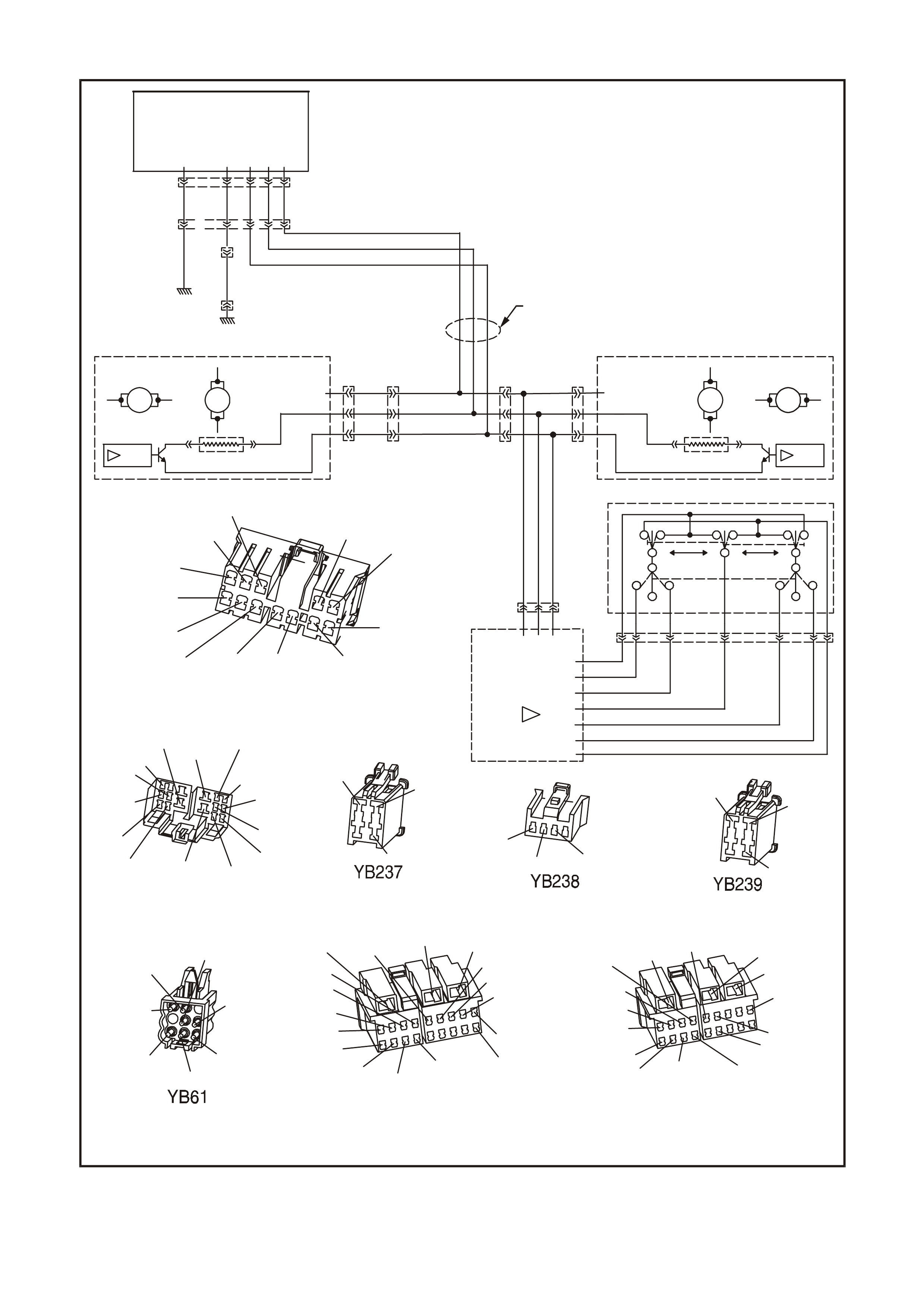
YB2 27
B/Y
Y(783)
(151)
R/G
R/O (929)
(782)
Y/BLU(540)
B/W
(139)
(925)
(920)
W/P
G
B/O BR/BLU (192) (641)
5
12
6
1
(24)
(156)
V
GY/R
(156)
YB226
POWER SEAT HARNESS
CONNECTOR
(641) (540)
O/B
O/W V/R (929)
(151)
BR
B/G
(192)
(1220)
(24)
(920)
V
G/W
LG
Y/B (783) B/BLU (782) (139)
P
V
(156)
(925)
(43)
Y
GY
RIGHT-HAND
MIRROR CONNECTOR
V(920) BR (929)
GY (925)
MIRROR SWITCH MODULE
CONNECTOR
VBR GY
(920)
(929) (925)
LEFT HAND MI RROR
CONNECTOR
V
(925) BR (929)
GY
(920)
MIRROR SWITCH
CONNECTOR
(911)
BR (909)
(908)
GY V
(905)
(904)
LBLU
Y
(920)
(929)
P
B/BLU
123456789
123456789
RIGHT-H AND FRONT DOOR
HA RNESS CONNECTOR
YB7 6
(1145)
(195)
(293)
(193)
(925)
(920) (929) (1126)
(673)
O/B
BR/R
BLU/B
LG/Y
G/O
GY
VBR W/BLU
(295)
B/Y (156)
(139)
(394)
BLU/W B/BLU
V/W
P
(672)
(200)
(197)
(117)
BR/W
LG
G
123456789
123456789
YB77
LEFT-HAN D FRONT DO OR
HA RNESS CONNECTOR
(1145)
(294)
(194)
(925)
(920) (929) (1124)
(667)
O/B
B/R
BR/O G
GY
VBR W/BLU
(195)
BR/R
B/Y
(394)
(666)
BLU
B/BLU
V/W
(295)
(118)
(201)
T
GY
MIRROR MOTORS MIRROR M OTORS
MSDB MSDB
+12V +12V
MIRROR HEATER MIRROR HEATER
V
V
SERIAL DATA SERIAL DATA
YB77
VERTICAL VERTICAL
LEFT-HAND MIRROR RIGHT-HAND MIRROR
H
H
YB239
HORIZONTAL HORIZONTAL
GND GND
MIRROR
SERIAL
DATA
BUS.
GY (925)
BR (929)
V(920)
GND
YB61
R
BLU
(920)
BR
GY
(911)
(929)
GY
LR
B/R
B
LBLU
Y(905)
MIRROR SWITCH
W
12V
L
Y
G
V
S
YB238
(904)
P
BR
B
(909)
(908)
V
BR (929)
(925)
GY
(920)
N
MIRROR SWITCH
MODULE
E
GY YB76
BR
YB237
(
929)
V
(
925)
(
920)
B/BLU
YE114
(151)
YB39
LOC. E6
LOC. E3
(156)
B/G
YB226
GY/R
YB227
R/G
W/P
R/O
G+12V
SERIAL DATA
GND
GND
GND
SEAT CONTROL
MODULE
POWER CO NNECTOR
WH1A7009
Figure 1A7-14

MIRROR POWER WIRING SHORT CIRCUIT TEST PROCEDURE
STEP ACTION VALUE YES NO
1 • Has the Vehicle Interface Test been carried out? Go to Step 2. Go to Vehicle
Interface Test in this
Section.
2 • Remove the lower side cover from the driver’s
seat to gain access to the seat control module.
• Disconnect the power connector YB227.
• Using an ohmmeter, measure the resistance
between the mirror bus power circuit 929
(Red/Orange wire) and the mirror bus earth circuit
920 (White/Pink wire) at connector YB227.
• Is the reading as specified?
Below 10 ΩGo to Step 3. Replace faulty seat
control module.
Refer to 2.1 SEAT
CONTROL
MODULE in this
Section.
3 • Leave the ohmmeter connected between the
mirror bus power circuit 929 (Red/Orange wire)
and the mirror bus earth circuit 920 (White/Pink
wire) at connector YB227.
• Disconnect the mirror switch module at connector
YB238.
• Did the short circuit disappear after disconnecting
the mirror switch module?
Replace faulty mirror
switch module.
Refer to 2.6
MIRROR SWITCH
MODULE in this
Section.
Go to Step 4.
4 • Leave the ohmmeter connected between the
mirror bus power circuit 929 (Red/Orange wire)
and the mirror bus earth circuit 920 (White/Pink
wire) at connector YB227.
• Disconnect the right-hand mirror at connector
YB237.
• Did the short circuit disappear after disconnecting
the right-hand mirror?
Replace faulty right-
hand mirror. Refer to
Section 1A5 FRONT
AND REAR DOORS.
Go to Step 5.
5 • Leave the ohmmeter connected between the
mirror bus power circuit 929 (Red/Orange wire)
and the mirror bus earth circuit 920 (White/Pink
wire) at connector YB227.
• Disconnect the left-hand mirror at connector
YB239.
• Did the short circuit disappear after disconnecting
the left-hand mirror?
Replace faulty left-
hand mirror. Refer to
Section 1A5 FRONT
AND REAR DOORS.
Go to Step 6.
6 • Using an ohmmeter, measure the resistance
between the mirror bus power circuit 929
(Red/Orange wire) and the earth circuit 151
(Red/Green wire) at connector YB227.
• Is the reading as specified?
Below 10 ΩCheck circuit 929 or
151 and repair as
necessary.
Check circuit 929 or
920 and repair as
necessary.
WHEN ALL DIAGNOSIS AND REPAIRS ARE COM PLETED, VERIFY CORRECT OPERATION

MIRROR BUS SHORT CIRCUIT TEST
INTRODUCTION
This test checks for a short circuit between the mirror serial data circuit and the mirror power and earth circuits. The
location of the seat control module connectors is shown in Fig. 1A7-12. For circuit diagram and other connector
information, refer to Fig. 1A7-14.
TEST DESCRIPTION
The various steps in the Mirror Bus Short Circuit Test verify the following functions:
Step 1 — Ensures that the Vehicle Interface Test is carried out eliminate other possible faults.
Step 2 — Checks for an open circuit or disconnected component in the mirror circuit.
Step 3 — Checks if the seat control module has detected a short circuit in the mirror bus.
Step 4 — Checks for a short circuit between the mirror bus serial data and mirror bus earth circuits at the power
seat harness connector YB226.
Step 5 — Checks for a short circuit between the mirror bus serial data and the seat earth, the seat control module
earth and the mirror bus earth circuits at the power connector YB227.
Step 6 — Checks for a short circuit between the mirror bus serial data and mirror bus power circuits at the power
seat harness connector YB226.
Step 7 — Checks for a short circuit between the mirror bus serial data and the seat motor power, the seat control
module power and the mirror bus power circuits at the power connector YB227.
Step 8 — Determines if there is a short circuit to earth in the mirror switch module.
Step 9 — Determines if there is a short circuit to earth in the right-hand mirror assembly.
Step 10 — Determines if there is a short circuit to earth in the left-hand mirror assembly .
Step 11 — Determines if there is a short circuit to a power circuit in the mirror switch module.
Step 12 — Determines if there is a short circuit to a power circuit in the right-hand mirror assembly.
Step 13 — Determines if there is a short circuit to a power circuit in the left-hand mirror assembly or a circuit wiring
problem.
MIRROR BUS SHORT CIRCUIT TEST PROCEDURE
STEP ACTION VALUE YES NO
1 • Has the Vehicle Interface Test been carried out? Go to Step 2. Go to Vehicle
Interface Test in this
Section.
2 • Remove the lower side cover from the driver’s
seat to gain access to the seat control module.
• Disconnect the power connector YB227.
• Using an ohmmeter, measure the resistance
between the mirror serial data bus circuit 925
(Green wire) and the mirror bus earth circuit 920
(White/Pink wire) at connector YB227.
• Is the reading as specified?
Above
25 kΩSerial data bus or
earth circuit open
circuit or
disconnected
between power seat
harness connector
and mirrors and
mirror switch. Repair
as necessary.
Go to Step 3.
3 • Check for DTC 15. Refer to Read Diagnostic
Trouble Code in this Section.
• Has DTC 15 set?
Go to Step 4. Go to Step 6.
4 • Using an ohmmeter, measure the resistance
between the mirror serial data bus circuit 925
(Green wire) and the mirror bus earth circuit 920
(White/Pink wire) at connector YB227.
• Is the reading as specified?
Below
10 kΩGo to Step 8. Go to Step 5.

MIRROR BUS SHORT CIRCUIT TEST PROCEDURE (continued)
STEP ACTION VALUE YES NO
5 • Using an ohmmeter, measure the resistance
between the mirror serial data bus circuit 925
(Green wire) and each of the following circuits at
connector YB227:
◊ seat earth circuit 156 (Grey/Red wire),
◊ module electronics earth circuit 151
(Red/Green wire), and
◊ mirror bus earth circuit 920 (White/Pink wire).
• Are the readings as specified?
Below
10 kΩCheck and repair
faulty circuit as
necessary.
Replace faulty seat
control module.
Refer to 2.1 SEAT
CONTROL
MODULE in this
Section.
6 • Disconnect the power seat harness connector
YB226 from the seat control module.
• Using an ohmmeter, measure the resistance
between the mirror serial data bus circuit 925
(Grey wire) and the mirror power circuit 929
(Brown wire) at connector YB226.
• Is the reading as specified?
Below
10 kΩGo to Step 11. Go to Step 7.
7 • Using an ohmmeter, measure the resistance
between the mirror serial data bus circuit 925
(Green wire) and each of the following circuits at
connector YB227:
◊ seat motor power circuit 540 (Yellow/Blue
wire),
◊ module electronics power circuit 641
(Black/Wh ite wire), and
◊ mirror power circuit 929 (Red/Orange wire).
• Are the readings as specified?
Below
10 kΩCheck and repair
faulty circuit as
necessary.
Replace faulty seat
control module.
Refer to 2.1 SEAT
CONTROL
MODULE in this
Section.
8 • Disconnect the mirror switch module at connector
YB238.
• Using an ohmmeter, measure the resistance
between the mirror serial data bus circuit 925
(Green wire) and each of the following circuits at
connector YB227:
◊ seat earth circuit 156 (Grey/Red wire),
◊ module electronics earth circuit 151
(Red/Green wire), and
◊ mirror bus earth circuit 920 (White/Pink wire).
• Did the short circuit disappear after disconnecting
the mirror switch module?
Replace faulty mirror
switch module.
Refer to 2.6
MIRROR SWITCH
MODULE in this
Section.
Go to Step 9.
9 • Disconnect the right-hand mirror at connector
YB237.
• Using an ohmmeter, measure the resistance
between the mirror serial data bus circuit 925
(Green wire) and each of the following circuits at
connector YB227:
◊ seat earth circuit 156 (Grey/Red wire),
◊ module electronics earth circuit 151
(Red/Green wire), and
◊ mirror bus earth circuit 920 (White/Pink wire).
• Did the short circuit disappear after disconnecting
the right-hand mirror?
Replace faulty right-
hand mirror. Refer to
Section 1A5 FRONT
AND REAR DOORS.
Go to Step 10.
10 • Disconnect the left-hand mirror at connector
YB239.
• Using an ohmmeter, measure the resistance
between the mirror serial data bus circuit 925
(Green wire) and each of the following circuits at
connector YB227:
◊ seat earth circuit 156 (Grey/Red wire),
◊ module electronics earth circuit 151
(Red/Green wire), and
◊ mirror bus earth circuit 920 (White/Pink wire).
• Did the short circuit disappear after disconnecting
the left-hand mirror?
Replace faulty left-
hand mirror. Refer to
Section 1A5 FRONT
AND REAR DOORS.
Check circuits 925,
156, 151 and 920
and repair as
necessary.

MIRROR BUS SHORT CIRCUIT TEST PROCEDURE (continued)
STEP ACTION VALUE YES NO
11 • Disconnect the mirror switch module at connector
YB238.
• Using an ohmmeter, measure the resistance
between the mirror serial data bus circuit 925
(Green wire) and each of the following circuits at
connector YB227:
◊ seat motor power circuit 540 (Yellow/Blue
wire),
◊ module electronics power circuit 641
(Black/Wh ite wire), and
◊ mirror power circuit 929 (Red/Orange wire).
• Did the short circuit disappear after disconnecting
the mirror switch module?
Replace faulty mirror
switch module.
Refer to 2.6
MIRROR SWITCH
MODULE in this
Section.
Go to Step 12.
12 • Disconnect the right-hand mirror at connector
YB237.
• Using an ohmmeter, measure the resistance
between the mirror serial data bus circuit 925
(Green wire) and each of the following circuits at
connector YB227:
◊ seat motor power circuit 540 (Yellow/Blue
wire),
◊ module electronics power circuit 641
(Black/Wh ite wire), and
◊ mirror power circuit 929 (Red/Orange wire).
• Did the short circuit disappear after disconnecting
the right-hand mirror?
Replace faulty right-
hand mirror. Refer to
Section 1A5 FRONT
AND REAR DOORS.
Go to Step 13.
13 • Disconnect the left-hand mirror at connector
YB239.
• Using an ohmmeter, measure the resistance
between the mirror serial data bus circuit 925
(Green wire) and each of the following circuits at
connector YB227:
◊ seat motor power circuit 540 (Yellow/Blue
wire),
◊ module electronics power circuit 641
(Black/Wh ite wire), and
◊ mirror power circuit 929 (Red/Orange wire).
• Did the short circuit disappear after disconnecting
the left-hand mirror?
Replace faulty left-
hand mirror. Refer to
Section 1A5 FRONT
AND REAR DOORS.
Check circuits
925,540, 641 and
929 and repair as
necessary.
WHEN ALL DIAGNOSIS AND REPAIRS ARE COM PLETED, VERIFY CORRECT OPERATION

MIRROR BUS WIRING TEST
INTRODUCTION
This test checks the voltage distribution within the mirror circuit. The location of the seat control module connectors
is shown in Fig. 1A7-12. For circuit diagram and other connector information, refer to Fig. 1A7-14.
TEST DESCRIPTION
The various steps in the Mirror Bus Wiring Test verify the following functions:
Step 1 — Ensures that the Vehicle Interface Test is carried out eliminate other possible faults.
Step 2 — Checks for correct voltage distribution in the mirror circuit.
Step 3 — Determines if the fault is isolated to an individual circuit.
Step 4 — Determines if there is a fault in the mirror switch module.
Step 5 — Isolates the fault to a circuit wiring problem or defective seat control module.
MIRROR BUS WIRING TEST PROCEDURE
STEP ACTION VALUE YES NO
1 • Has the Vehicle Interface Test been carried out? Go to Step 2. Go to Vehicle
Interface Test in this
Section.
2 • Turn the ignition switch to the IGN position.
NOTE: Use adaptors from test adaptor kit KM-609 to
back probe the terminals of power connector YB227.
• Using a multimeter, measure the voltage between
the mirror bus earth circuit 920 (Violet wire) and
each of the following circuits at the mirror switch
module connector YB238:
◊ mirror bus power circuit 929 (Brown wire), and
◊ mirror bus serial data circuit 925 (Grey wire).
• Using a multimeter, measure the voltage between
the mirror bus earth circuit 920 (Violet wire) and
each of the following circuits at the left-hand mirror
connector YB239:
◊ mirror bus power circuit 929 (Brown wire), and
◊ mirror bus serial data circuit 925 (Grey wire).
• Using a multimeter, measure the voltage between
the mirror bus earth circuit 920 (Violet wire) and
each of the following circuits at the right-hand
mirror connector YB237:
◊ mirror bus power circuit 929 (Brown wire), and
◊ mirror bus serial data circuit 925 (Grey wire).
• Are the readings as specified?
Power
circuit = 11
– 12 V
Data circuit
= 8 – 10 V
Replace faulty
mirror. Refer to
Section 1A5 FRONT
AND REAR DOORS.
Go to Step 3.
3 • Are the readings as specified at some but not all
connectors? Power
circuit = 11
– 12 V
Data circuit
= 8 – 10 V
Check and repair
faulty circuit as
necessary.
Go to Step 4.
4 • Is there a mirror switch problem? Power
circuit = 11
– 12 V
Data circuit
= 8 – 10 V
Go to Mirror Switch
Test in this Section. Go to Step 5.

STEP ACTION VALUE YES NO
5 • Remove the lower side cover from the driver’s
seat to gain access to the seat control module.
• Ensure that the ignition switch is in the IGN
position.
NOTE: Use adaptors from test adaptor kit KM-609 to
back probe the terminals of power connector YB227.
• Using a multimeter, measure the voltage between
the mirror bus earth circuit 920 (White/Pink wire)
and each of the following circuits at the power
connector YB227 on the seat control module:
◊ mirror bus power circuit 929 (Red/Orange
wire), and
◊ mirror bus serial data circuit 925 (Green wire).
• Are the readings as specified?
Power
circuit = 11
– 12 V
Data circuit
= 8 – 10 V
Check and repair
faulty circuit as
necessary.
Replace faulty seat
control module.
Refer to 2.1 SEAT
CONTROL
MODULE in this
Section.
WHEN ALL DIAGNOSIS AND REPAIRS ARE COM PLETED, VERIFY CORRECT OPERATION

MANUAL SEAT MOVE TEST
INTRODUCTION
This test verifies the correct operation of each of the four motors in the seat assembly, as well as the eight-way seat
position switch. The location of the seat control module connectors is shown in Fig. 1A7-12. For circuit diagram and
other connector information, refer to Fig. 1A7-15.
TEST DESCRIPTION
The various steps in the Manual Seat Move Test verify the following functions:
Step 1 — Ensures that the Vehicle Interface Test is carried out eliminate other possible faults.
Step 2 — Checks for correct operation of each seat drive motor, and determines if a drive motor stall condition
exists.
Step 3 — Determines if there is a fault with a drive motor or switch.
Step 4 — Verifies correct seat drive motor supply voltage.
Step 5 — Isolates the fault to a drive motor.
Step 6 — Verifies correct seat drive motor operation.
Step 7 — Isolates the fault to a circuit wiring problem or redirects testing to the eight-way seat position switch circuit.
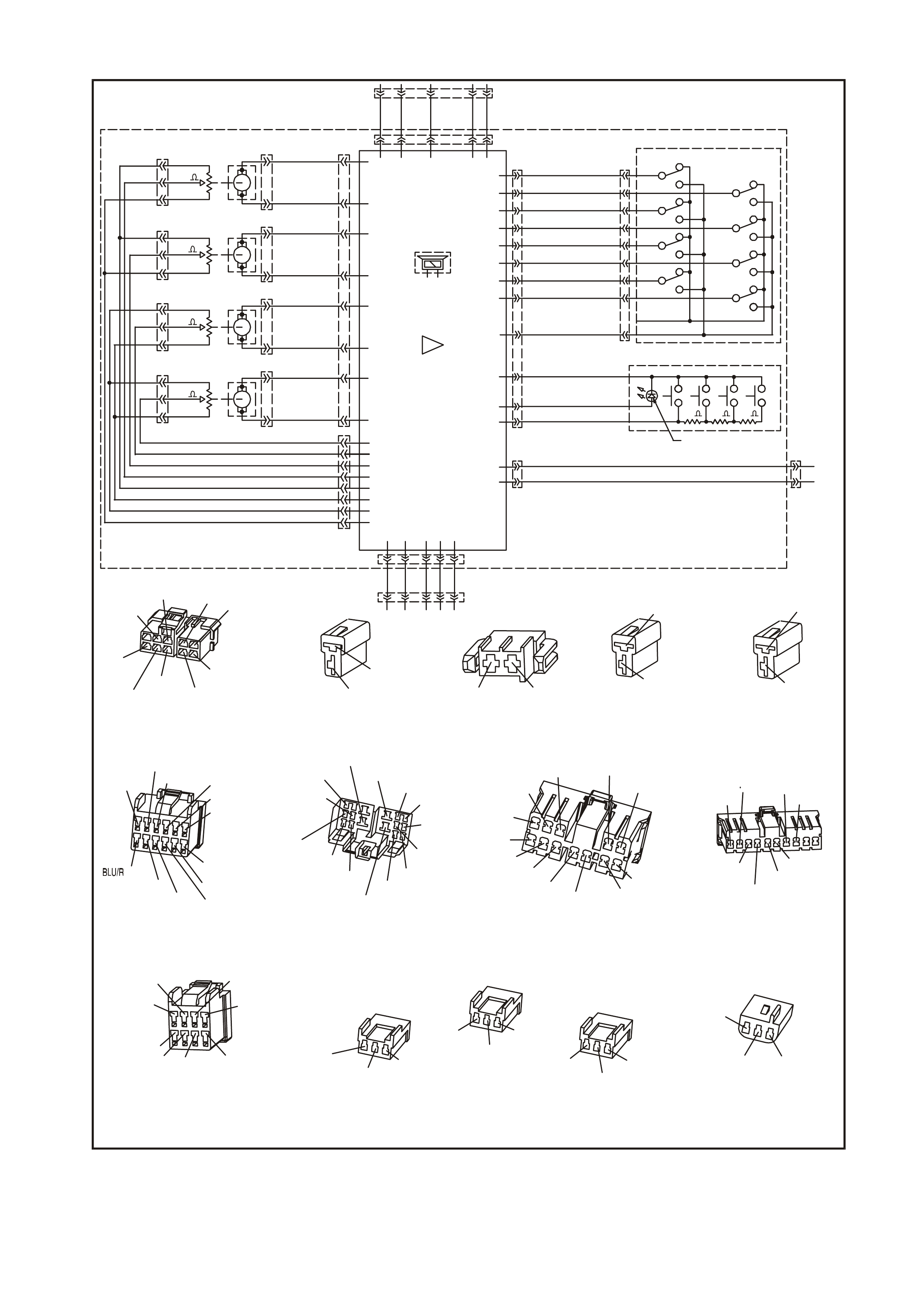
YB227
YB220
(614)
RECLINE UP
AFT
Y/P
IGN.
12V
EIGHT-WAY SEAT POSITION SWITCH
SPEAKER
M2
DIAGNOSTIC
LED
SEAT
CONTROL MODULE
B
(1029)
R/O
FRT UP
G/GY
(1024)
(621)
RECLINE DN
RR UP
(1023)
B/W
DRIVERS SE AT
PRIORITY 1
12V
YB227
M3
Y
(1025)
(613)
(24) (24)
(192) (192)
FWD
FRT DN
BLU/R
(1022)
YB225
PRIORITY 2
B/Y
(1028)
12V
DIP
G
(1026)
(1021)
V/Y
(1027)
W/P
V/G
MEMORY POSITION SWITCH
RR DN
M1
YB226
POSITION SIG 2.
POSITION SIG 3.
POSITION SIG 4.
POSITION SIG 1.
0V
+5V
+5V
0V
(565)
(567)
(562)
(564)
(566)
(563)
(560)
(561)
R/G
Y
R
V
Y/W
BR
B
G
YB229
YB226
(177)
YB222
YB228
(190)
MO TOR 3
(179)
(189)
B
GY
YB221
RECLINE
MO TOR 1
RR UP/RR DN
YB223 W
(180)
YB224
(176)
R/B
BLU/R
BR
FWD/AFT
MO TOR 4
(181)
MO TOR 2
(178)
G/Y
BLU
FRT UP/FRT DN
YB235
YB235
YB235
YB236
Y/BLU
B/W
B/O
B/Y
Y
LG
VV/RBR/BLU
REVERSE
SIG
HEATED REAR
WINDOW
SIG
YB227
GY/R
R/G
W/P
R/O
G
WH1A7010A
YB227
POTENTIOME TER CONNECTO R
YB235
MOTOR POTENTIO METER
CONNECTORS
YB236
RECLINE MOT OR
POTENTIOME TER CONNECTO R
YB225
MEMORY AND POSITI ON
CONNE CTOR
YB226
POWER SEAT HARNESS
CONNECTOR
YB227
POWER CONNECTOR
YB228
DRIVE MOTO R CONNECTOR
(1129)
YB220
EIGHT-WAY SEAT POSITION
SWITCH CONNECTOR
(1026)
(1027)
(1025)
(1024)
(1021) (1022)
(1023)
(1028)
R/O
G
W/P
Y
B/Y
B/W BLU/R
V/Y G/GY
YB222
RECLINE MOT OR
CONNECTOR
BLU/R
(181) (177)
B
YB223
FORWARD/AFT
MOTOR CONNECTOR
(178)
W
(176)
GY
YB224
FRONT UP/DOWN
MOTOR CONNECTOR
(180)
(189)
BR
BLU
(1021)
(1025)
(1026)
(1022)
(613) (614)
(1029)
(1024)
(1023)
(1028)
(1027)
G
Y
V/Y
Y/P
W/P
B/Y
B/W
G/GY
R/O
V/G
7
1
61
7
12
18
4
5
B
(612)
(641) (540)
O/B
O/W V/R
(929)
(151)
BRB/G
(192)
(1220)
(24)
(920)
V
G/W LGY/B
(783)
B/BLU
(782)
(139)
P
V
(156)
(43)
Y
GY
B/Y
Y
(783)
(151)
R/G
R/O
(929)
(782)
Y/BLU
(540)
B/W
(139)
(925)
(920)
W/P
GB/O
BR/BLU
(192) (641)
5
12
6
1110
(24)
V
(156)
GY/R
R/B G/Y
B
BLU/R WGY
BR BLU
(179)
(190)
(177)
(181)
(176) (178)
(180)(189)
(565)
BR
V
R
Y/W
G
R/G YB
(564)
(566)(567)
(560)
(562)
(563)
(561)
REAR UP/DOWN
BR/G Y
(566) (560) (567)
FORWARD/AFT
BR
V
Y/W
(565) (563) (564)
FRONT UP/DOWN
RV
BR
(565) (561) (564)
GB
Y
(566)
(562)
(567)
(925)
YB226
+12V
SERIAL DATA
GND
GND
GND
(MIRROR
SERIAL
DATA
BUS)
10K
10K
10K
10K
330
330 330
YB221
REAR UP/DOWN
MOTOR CONNECTOR
(179)
(190)
G/Y
R/B
Figure 1A7-15

MANUAL SEAT MOVE TEST PROCEDURE
STEP ACTION VALUE YES NO
1 • Has the Vehicle Interface Test been carried out? Go to Step 2. Go to Vehicle
Interface Test in this
Section.
2 • Ensure that the ignition switch is in the OFF
position and remove the key.
• Using the eight-way seat position switch, move the
seat in each direction a few times.
• Does a motor only run in small steps with the
switch in one position for more than 2 seconds?
Go to Drive Motor
and Motor
Potentiometer Test
in this Section.
Go to Step 3.
3 • Did some motors run normally while others did not
run at all? Go to Step 5. Go to Vehicle
Interface Test in this
Section.
If no fault is found by
the Vehicle Interface
Test, go to the
Diagnostic Switch
Test in this Section.
If no fault is found by
the Diagnostic
Switch Test, go to
Step 4.
4 • Remove the lower side cover from the driver’s
seat to gain access to the seat control module.
NOTE: Use adaptors from test adaptor kit KM-609 to
back probe the terminals of power connector YB227.
• Using a multimeter, measure the voltage across
the seat motor power circuit 540 (Yellow/Blue
wire) and the seat earth circuit 156 (Grey/Red
wire) at the power connector YB227 on the seat
control module.
• Is the voltage as specified?
Battery
Voltage Go to Step 5. Blown circuit breaker
F2 or fusible link FJ,
or faulty circuit 540
or 156, or flat
battery. Repair as
necessary.
5 • Disconnect the non-functional motor at the motor
connector and connect the motor to a battery via a
pair of fused wires to drive the motor in one
direction.
• Reverse the motor connections to drive the motor
in the opposite direction.
• Did the motor operate when the battery voltage
was connected?
Go to Step 6. Replace faulty
motor. Refer to 2.4
DRIVE MOTOR in
this Section.
6 • If the motor drive was obstructed and freed at
Step 5, connect the motor and use the eight-way
switch to move the seat in each direction.
• Did the seat move correctly under control of the
eight-way switch?
End of diagnosis. Go to Step 7.
7
NOTE: Use adaptors from test adaptor kit KM-609 to
back probe the terminals of power connector YB227.
• Using a multimeter, measure the voltage across
the appropriate motor circuit at the drive motor
connector YB228 on the seat control module while
operating the eight-way switch.
• Using a multimeter, measure the voltage across
the appropriate motor connector (YB221, YB222,
YB223 or YB224) while operating the eight-way
switch.
• Are the readings as specified?
YB228 =
12 V
Motor
connector
= 0 V
Repair faulty motor
circuit wiring. Go to Eight-way
Seat Position Switch
Test in this Section.
WHEN ALL DIAGNOSIS AND REPAIRS ARE COM PLETED, VERIFY CORRECT OPERATION
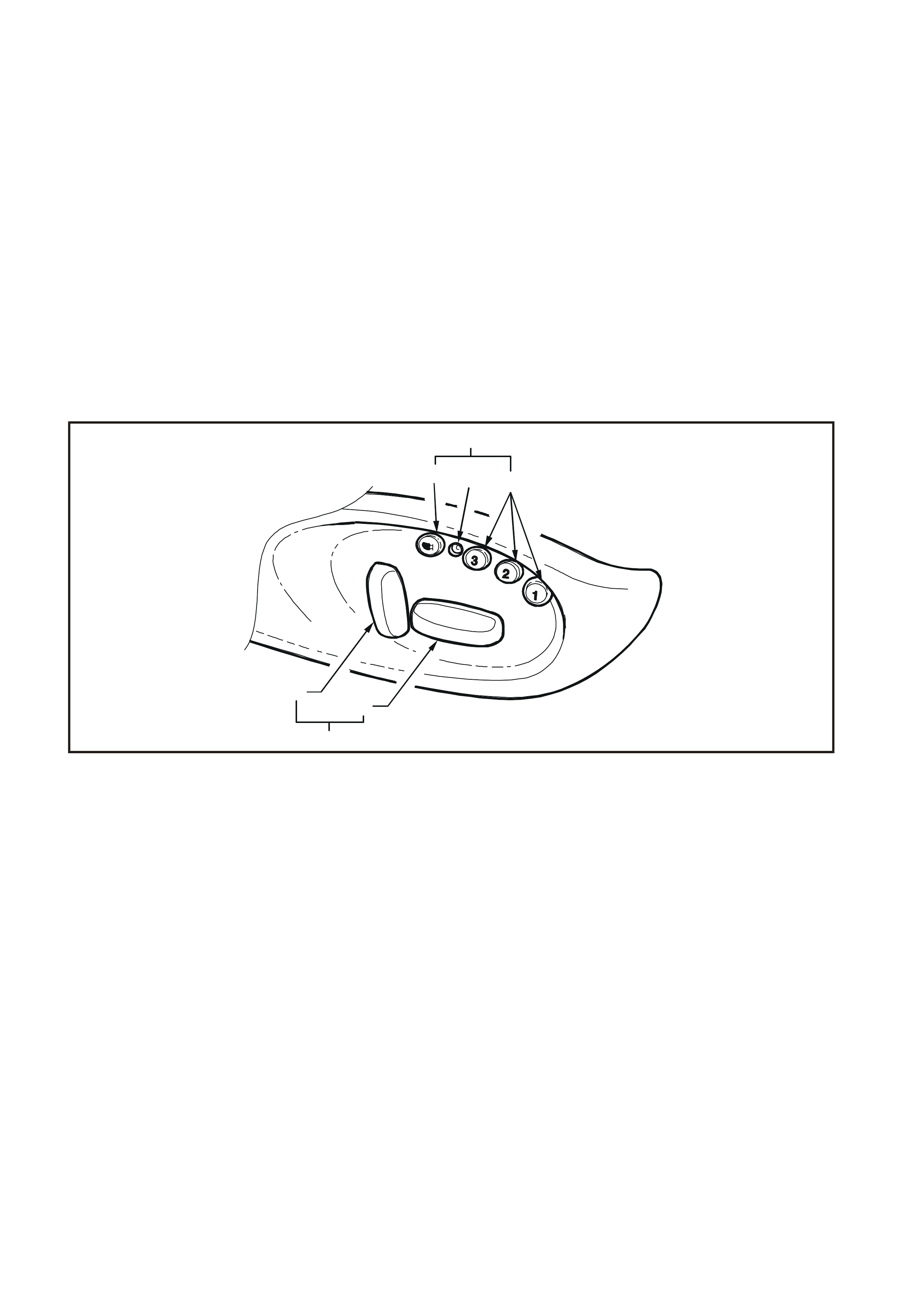
DIAGNOSTIC SWITCH TEST
INTRODUCTION
This test verifies the correct operation of each of the memory buttons and switches used in the memory seat and
mirror system, refer to Fig. 1A7-16.
TEST DESCRIPTION
The various steps in the Diagnostic Switch Test verify the following functions:
Step 1 — Ensures that the Vehicle Interface Test is carried out eliminate other possible faults.
Step 2 — Enters the Diagnostic Switch Test mode and checks each button and switch sequentially.
Step 3 — Determines if there is a button or switch not making contact.
Step 4 — Determines if there is a shorted button or switch.
Step 5 — Test successful.
Step 6 — Isolates the fault to the memory position switch.
Step 7 — Isolates the fault to the eight-way seat position switch.
Step 8 — Isolates the fault to the mirror switch or the seat control module.
WH1A7002
123
65
7
4
Figure 1A7-16
1. Mirror Dip Button 4. Memory Position Switch 6. Backrest Recliner Angle Adjust
2. Diagnostic LED 5. Fore/Aft/Up/Down/Tilt Adjust 7. Eight-way Seat Position Switch
3. Memory Buttons

DIAGNOSTIC SWITCH TEST PROCEDURE
STEP ACTION VALUE YES NO
1 • Has the Vehicle Interface Test been carried out? Go to Step 2. Go to Vehicle
Interface Test in this
Section.
2 • Press and hold the mirror dip button and turn
ignition switch from OFF to IGN three times within
6 seconds. Leave the ignition switch in the IGN
position.
• After a constant tone sounds, press and hold
memory button 3 until a chime sounds
(approximately 1 second).
• Press and hold memory button 3 again for
1 second to enter the Diagnostic Switch Test
mode.
• Press the following in sequence:
◊ mirror dip button,
◊ memory button 3,
◊ memory button 2,
◊ memory button 1,
◊ backrest forward,
◊ backrest rearward,
◊ seat rear down,
◊ seat rear up,
◊ seat slide rearward,
◊ seat slide forward,
◊ seat front down,
◊ seat front up,
◊ right-hand mirror up,
◊ right-hand mirror out,
◊ right-hand mirror down,
◊ right-hand mirror in,
◊ left-hand mirror up,
◊ left-hand mirror in,
◊ left-hand mirror down, and
◊ left-hand mirror out.
• Did a tone sound when no button or switch was
pressed?
Stuck switch.
Go to Step 6. Go to Step 3.
3 • At Step 2, was there one or more buttons or
switches that did not produce a tone? Switch does not
make contact.
Go to Step 6.
Go to Step 4.
4 • At Step 2, did more than one button or switch
produce similar tones? Shorted switch.
Go to Step 6. Go to Step 5.
5 • Did a different tone sound for every button or
switch?
NOTE: The tones should increase in frequency, with
the mirror dip button being the lowest and the left-
hand mirror out being the highest.
Test successful.
End of diagnosis. Go to Step 6.
6 • Check the memory position switch.
• Did the fault occur in the memory position switch? Go to Memory
Button Test in this
Section.
Go to Step 7.
7 • Check the eight-way seat position switch.
• Did the fault occur in the eight-way seat position
switch?
Go to Eight-way
Manual Seat
Position Switch Test
in this Section.
Go to Step 8.
8 • Check the mirror switch.
• Did the fault occur in the mirror switch? Go to Mirror Switch
Test in this Section. Replace faulty seat
control module.
Refer to 2.1 SEAT
CONTROL
MODULE in this
Section.
WHEN ALL DIAGNOSIS AND REPAIRS ARE COM PLETED, VERIFY CORRECT OPERATION
MEMORY BUTTON TEST
INTRODUCTION
This test verifies the correct operation of the circuit of each memory button on the memory position switch. The
location of the seat control module connectors is shown in Fig. 1A7-12. For circuit diagram and other connector
information, refer to Fig. 1A7-15.
TEST DESCRIPTION
The resistance of the circuit of each memory button on the memory position switch is checked at the seat control
module memory and position switch connector YB225. This also checks the loom wiring to the switch.
MEMORY BUTTON TEST PROCEDURE
STEP ACTION VALUE YES NO
1 • Has the Vehicle Interface Test been carried out? Go to Step 2. Go to Vehicle
Interface Test in this
Section.
2 • Remove the lower side cover from the driver’s
seat to gain access to the seat control module.
• Disconnect the memory and position connector
YB225 from the seat control module.
• Connect an ohmmeter across circuit 621 (Black
wire) and circuit 613 (Yellow/Pink wire) at
connector YB225.
• When pressing the memory buttons, are the
ohmmeter readings as specified?
No buttons
=
> 1 MΩ
M1 =
continuity
M2 = 330 Ω
M3 = 660 Ω
DIP = 990 Ω
Replace faulty seat
control module.
Refer to 2.1 SEAT
CONTROL
MODULE in this
Section.
Replace faulty
memory position
switch. Refer to 2.2
MEMORY
POSITION SWITCH
in this Section.
WHEN ALL DIAGNOSIS AND REPAIRS ARE COM PLETED, VERIFY CORRECT OPERATION
EIGHT-WAY SEAT POSITION SWITCH TEST
INTRODUCTION
This test verifies the correct operation of the circuit of each switch position of the eight-way seat position switch. The
location of the seat control module connectors is shown in Fig. 1A7-12. For circuit diagram and other connector
information, refer to Fig. 1A7-15.
TEST DESCRIPTION
The resistance of the circuit of each position of the eight-way seat position switch is checked at the seat control
module memory and position connector YB225. This also checks the loom wiring to the switch.
EIGHT-WAY SEAT POSITION SWITCH TEST PROCEDURE
STEP ACTION VALUE YES NO
1 • Has the Vehicle Interface Test been carried out? Go to Step 2. Go to Vehicle
Interface Test in this
Section.
2 • Remove the lower side cover from the driver’s
seat to gain access to the seat control module.
• Disconnect the memory and position connector
YB225 from the seat control module.
• Using an ohmmeter, measure the resistance
between the switch earth circuit 1029
(Red/Orange wire) and each of the following
circuits at connector YB225:
◊ backrest up circuit 1025 (Yellow wire),
◊ backrest down circuit 1026 (Green wire),
◊ seat back circuit 1027 (White/Pink wire),
◊ seat forward circuit 1028 (Black/Yellow wire),
◊ seat front up circuit 1024 (Green/Grey wire),
◊ seat front down circuit 1023 (Black/White
wire),
◊ seat rear up circuit 1022 (Blue/Red wire), and
◊ seat rear down circuit 1021 (Violet/Yellow
wire).
• Are the readings as specified?
Function
selected =
continuity
Function not
selected =
open circuit
Replace faulty seat
control module.
Refer to 2.1 SEAT
CONTROL
MODULE in this
Section.
Replace faulty
driver’s eight-way
seat position switch.
Refer to 2.3 EIGHT-
WAY SEAT
POSITION SWITCH
in this Section.
WHEN ALL DIAGNOSIS AND REPAIRS ARE COM PLETED, VERIFY CORRECT OPERATION
MIRROR SWITCH TEST
INTRODUCTION
This test verifies the correct operation of the circuit of each switch position of the mirror switch. The location of the
seat control module connectors is shown in Fig. 1A7-12. For circuit diagram and other connector information, refer
to Fig. 1A7-14.
TEST DESCRIPTION
The mirror switch is tested using an ohmmeter.
MIRROR SWITCH TEST PROCEDURE
STEP ACTION VALUE YES NO
1 • Has the Vehicle Interface Test been carried out? Go to Step 2. Go to Vehicle
Interface Test in this
Section.
2 • Remove the lower side cover from the driver’s
seat to gain access to the seat control module.
• Disconnect the power connector YB227 from the
seat control module.
• Remove the mirror switch from the driver’s door
and test the mirror switch. Refer to Section 12H
ELECTRICALLY ADJUSTABLE REAR VISION
MIRRORS of the VT
Series II Service Information.
• Did the old mirror switch test OK?
Install old mirror
switch. Replace
faulty mirror switch
module. Refer to 2.6
MIRROR SWITCH
MODULE in this
Section.
Replace faulty
switch. Refer to
Section 12H
ELECTRICALLY
ADJUSTABLE
REAR VISION
MIRRORS of the VT
Series II Service
Information.
WHEN ALL DIAGNOSIS AND REPAIRS ARE COM PLETED, VERIFY CORRECT OPERATION

LED TEST
INTRODUCTION
This test verifies the correct operation of the circuit of the diagnostic LED on the memory position switch. The
location of the seat control module connectors is shown in Fig. 1A7-12. For circuit diagram and other connector
information, refer to Fig. 1A7-14.
TEST DESCRIPTION
The LED is tested using the diode test function of a multimeter.
LED TEST PROCEDURE
STEP ACTION VALUE YES NO
1 • Has the Vehicle Interface Test been carried out? Go to Step 2. Go to Vehicle
Interface Test in this
Section.
2 • Remove the lower side cover from the driver’s
seat to gain access to the seat control module.
• Disconnect the memory and position connector
YB225 from the seat control module.
• Using a multimeter set to the diode test mode,
measure between circuit 621 (Black wire) and
circuit 614 (Violet/Green wire) at connector YB225
and note the reading.
• Reverse the multimeter leads and note the new
reading.
• Are the readings as specified?
Between
1 - 2 V in
one
direction
Maximum
scale in the
other
direction
Go to Step 3. Faulty LED.
Replace memory
position switch.
Refer to 2.2
MEMORY
POSITION SWITCH
in this Section.
3 • Check for loose or damaged connections at
connector YB225 and at the memory position
switch.
• Loose or damaged connection found?
Repair connections
as necessary, or
replace memory
position switch.
Refer to 2.2
MEMORY
POSITION SWITCH
in this Section.
Go to Vehicle
Interface Test in this
Section.
If no fault is found by
the Vehicle Interface
Test, replace the
seat control module.
Refer to 2.1 SEAT
CONTROL
MODULE in this
Section.
WHEN ALL DIAGNOSIS AND REPAIRS ARE COM PLETED, VERIFY CORRECT OPERATION

SLEEP MODE TEST
INTRODUCTION
This test checks the correct operation of the sleep mode function.
TEST DESCRIPTION
The various steps in the Sleep Mode Test verify the following functions:
Step 1 — Ensures that the Vehicle Interface Test is carried out eliminate other possible faults.
Step 2 — Checks for correct entry into sleep mode.
Step 3 — Isolates a fault to the seat control module.
Step 4 — Isolates a fault to the seat control module or indicates successful completion of the test.
SLEEP MODE TEST PROCEDURE
STEP ACTION VALUE YES NO
1 • Has the Vehicle Interface Test been carried out? Go to Step 2. Go to Vehicle
Interface Test in this
Section.
2 • Ensure that the rear window demister switch is off.
• Turn the ignition switch to the IGN position then to
the OFF position.
• Do not operate any keys or switches for
5 minutes.
• Did the seat LED turn off after not operating any
keys or switches for 5 minutes?
Go to Step 3. Go to LED Test in
this Section.
If no fault is found in
this test, go to
Diagnostic Switch
Test in this Section.
If no fault is found in
this test, go to
Vehicle Interface
Test in this Section.
If no fault is found by
the Vehicle Interface
Test, replace the
seat control module.
Refer to 2.1 SEAT
CONTROL
MODULE in this
Section.
3 • Can both mirrors be moved with the mirror switch? Replace faulty seat
control module.
Refer to 2.1 SEAT
CONTROL
MODULE in this
Section.
Go to Step 4.
4 • Can the seat be moved with the eight-way seat
position switch? Sleep mode
functioning correctly.
End of diagnosis.
Replace faulty seat
control module.
Refer to 2.1 SEAT
CONTROL
MODULE in this
Section.
WHEN ALL DIAGNOSIS AND REPAIRS ARE COM PLETED, VERIFY CORRECT OPERATION

MANUAL MIRROR MOVE TEST
INTRODUCTION
This test checks the correct operation of the mirror circuit. The location of the seat control module connectors is
shown in Fig. 1A7-12. For circuit diagram and other connector information, refer to Fig. 1A7-15.
TEST DESCRIPTION
The various steps in the Manual Mirror Move Test verify the following functions:
Step 1 — Ensures that the Vehicle Interface Test is carried out eliminate other possible faults.
Step 2 — Checks for correct entry into the Vehicle Interface Test.
Step 3 — Checks the reverse gear selection.
Step 4 — Isolates a reverse gear selection problem to a circuit wiring fault or a defective seat control module.
Step 5 — Checks the rear window demister and mirror heater selection.
Step 6 — Isolates a rear window demister and mirror heater selection problem to a circuit wiring fault or a
defective seat control module.
Step 7 — Checks for an intermittent fault in the ignition circuit.
Step 8 — Checks the correct identification of priority keys.
Step 9 — Checks the priority signal lines from the BCM.
Step 10 — Identifies that a DTC is stored, or successful completion of the test.
MANUAL MIRROR MOVE TEST PROCEDURE
STEP ACTION VALUE YES NO
1 • Has the Vehicle Interface Test been carried out? Go to Step 2. Go to Vehicle
Interface Test in this
Section.
2 • Remove the lower side cover from the driver’s
seat to gain access to the seat control module,
which is required during this test.
• Press and hold the mirror dip button and turn
ignition switch from OFF to IGN three times within
6 seconds. Leave the ignition switch in the IGN
position.
• After a constant tone sounds, press and hold
memory button 1 until a chime sounds
(approximately 1 second).
• Press and hold memory button 3 for 1 second to
enter the Vehicle Interface Test mode.
• A repetitive chime sounds to indicate that the
Vehicle Interface Test has been successfully
entered.
• Did the repetitive chime change to an alternating
frequency (siren)?
Go to Read
Diagnostic Trouble
Code in this Section.
If DTC 12 is
displayed, got to
Diagnostic Switch
Test in this Section.
Go to Step 3.
3 • Select reverse gear.
• Did the repetitive chime change tone? Go to Step 5. Go to Step 4.
4 • Ensure that the ignition switch is still in the IGN
position.
NOTE: Use adaptors from test adaptor kit KM-609 to
back probe the terminals of power connector YB227.
• Using a multimeter, measure the reverse gear
signal voltage on circuit 24 (Violet wire) at the
power connector YB227 while shifting between
reverse and park.
• Are the readings as specified?
Reverse =
12 V
Park = 0 V
Replace faulty seat
control module.
Refer to 2.1 SEAT
CONTROL
MODULE in this
Section.
Check circuit 24 and
repair as necessary.
5 • Set the rear window demister switch to on.
• Did the repetitive chime change tone? Go to Step 7. Go to Step 6.

MANUAL MIRROR MOVE TEST PROCEDURE (continued)
STEP ACTION VALUE YES NO
6 • Ensure that the ignition switch is still in the IGN
position.
NOTE: Use adaptors from test adaptor kit KM-609 to
back probe the terminals of power connector YB227.
• Using a multimeter, measure the rear window
demister signal voltage on circuit 192 (Brown/Blue
wire) at the power connector YB227 while
switching between off and on.
• Are the readings as specified?
On = 12 V
Off = 0 V Replace faulty seat
control module.
Refer to 2.1 SEAT
CONTROL
MODULE in this
Section.
Check circuit 192
and repair as
necessary.
7 • Turn the ignition switch to the OFF position and
remove t he k ey.
• Did the repetitive chime change tone?
Go to Step 8. Intermittent fault in
the ignition circuit.
Check circuit 139
and repair as
necessary.
8 • Press the door unlock button on Priority Key 1.
• Press the door unlock button on Priority Key 2.
• Did the repetitive chime change tone with Key 1 or
Key 2?
Go to Step 10. Go to Step 9.
9 • Insert Priority Key 1 in the ignition switch.
NOTE: Use adaptors from test adaptor kit KM-609 to
back probe the terminals of power connector YB227.
• Using a multimeter, measure the priority 1 signal
voltage on circuit 782 (Black/Yellow wire) and the
priority 2 signal voltage on circuit 783 (Yellow
wire) at the power connector YB227 while
switching the ignition between OFF and IGN.
• Repeat the measurement of both signals for the
Priority Key 2.
• Are the readings as specified?
0.6 V in IGN
4 V in OFF Replace faulty seat
control module.
Refer to 2.1 SEAT
CONTROL
MODULE in this
Section.
Check circuits 782
or 783 from BCM to
seat control module
and repair as
necessary.
10 • Did a repeating tone of alternating frequency
sound? Go to Read
Diagnostic Trouble
Code in this Section.
A single burst of
three tones in
increasing frequency
indicates successful
test completion.
WHEN ALL DIAGNOSIS AND REPAIRS ARE COM PLETED, VERIFY CORRECT OPERATION
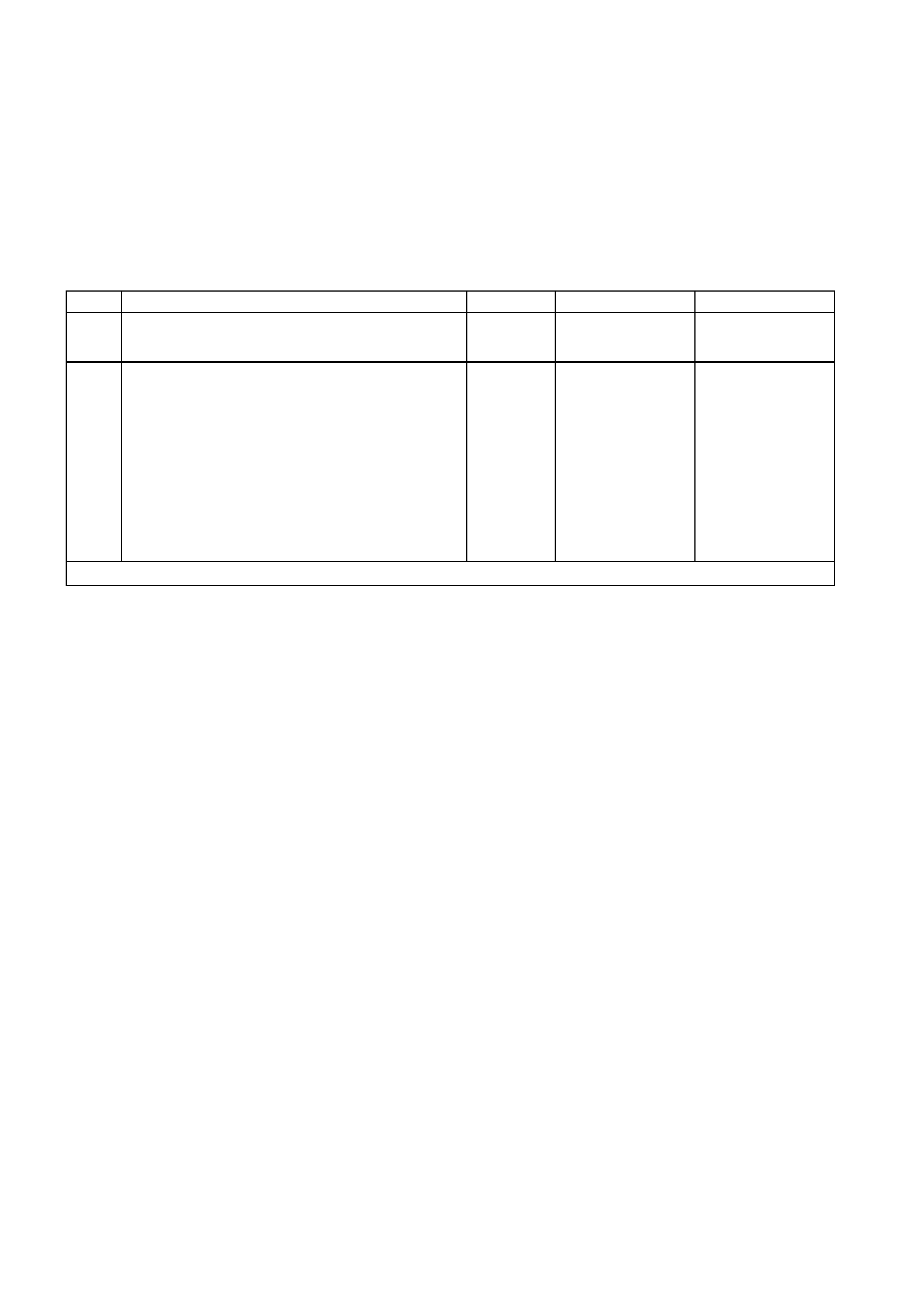
MIRROR RECALL TEST
INTRODUCTION
This test checks the correct operation of the mirror memory recall function.
TEST DESCRIPTION
The various steps in the Mirror Recall Test verify the following functions:
Step 1 — Ensures that the Vehicle Interface Test is carried out eliminate other possible faults.
Step 2 — Isolates the fault to a defective mirror.
MIRROR RECALL TEST PROCEDURE
STEP ACTION VALUE YES NO
1 • Has the Vehicle Interface Test been carried out? Go to Step 2. Go to Vehicle
Interface Test in this
Section.
2 • Press the memory buttons in the following
sequence, and allow the mirror to drive to the
appropriate position before pressing the next
button:
◊ memory button 2
◊ memory button 3
◊ memory button 2
◊ memory button 1
◊ memory button 2
• Did only one mirror show a memory recall
problem?
Replace faulty mirror
as appropriate.
Refer to Section 1A5
FRONT AND REAR
DOORS.
Replace both faulty
mirrors. Refer to
Section 1A5 FRONT
AND REAR DOORS.
WHEN ALL DIAGNOSIS AND REPAIRS ARE COM PLETED, VERIFY CORRECT OPERATION

MIRROR HEATER TEST
INTRODUCTION
This test checks the correct operation of the mirror heater function.
TEST DESCRIPTION
The various steps in the Mirror Heater Test verify the following functions:
Step 1 — Ensures that the Vehicle Interface Test is carried out eliminate other possible faults.
Step 2 — Sets the mirror heater circuit into operation.
Step 3 — Isolates the fault to a defective mirror circuit and redirects testing to further isolate wiring or
component failure.
Step 4 — Verifies input voltage, isolates the fault to a defective mirror circuit, or redirects testing to further isolate
wiring or component failure.
MIRROR HEATER TEST PROCEDURE
STEP ACTION VALUE YES NO
1 • Has the Vehicle Interface Test been carried out? Go to Step 2. Go to Vehicle
Interface Test in this
Section.
2 • Check that the external rear vision mirrors are
cold.
• Turn the ignition switch to the IGN position.
• Set the rear window demister switch to on.
• Did both mirrors get warm after 2 minutes?
Mirror heater works
correctly. Go to Step 3.
3 • Did only one of the two mirrors get warm? Go to Mirror Bus
Wiring Test in this
Section.
Go to Step 4.
4 • Ensure that the ignition switch is still in the IGN
position.
NOTE: Use adaptors from test adaptor kit KM-609 to
back probe the terminals of power connector YB227.
• Using a multimeter, measure the rear window
demister signal voltage on circuit 192 (Brown/Blue
wire) at the power connector YB227 while
switching between off and on.
• Are the readings as specified?
On = 12 V
Off = 0 V Go to Mirror Bus
Wiring Test in this
Section.
Check circuit 192
and repair as
necessary.
WHEN ALL DIAGNOSIS AND REPAIRS ARE COM PLETED, VERIFY CORRECT OPERATION

DRIVE MOTOR AND MOTOR POTENTIOMETER TEST
INTRODUCTION
This test checks the correct operation of the seat assembly drive motors, motor potentiometers and associated
circuits. The location of the seat control module connectors is shown in Fig. 1A7-12. For circuit diagram and other
connector information, refer to Fig. 1A7-15.
It may be necessary to remove the seat assembly to gain access to the drive motors and/or motor potentiometers
during this test.
TEST DESCRIPTION
The various steps in the Drive Motor and Motor Potentiometer Test verify the following functions:
Step 1 — Ensures that the Vehicle Interface Test is carried out eliminate other possible faults.
Step 2 — Performs the Drive Motor Potentiometer Calibration to ensure correct motor and sensor calibration.
Step 3 — Isolates the fault to a defective drive motor.
Step 4 — Identifies successful completion of the test.
Step 5 — Isolates the fault to a circuit wiring problem or a defective seat control module.
Step 6 — Identifies successful completion of the test.
Step 7 — Isolates the fault to a defective drive motor potentiometer.
Step 8 — Isolates the fault to a circuit wiring problem or a defective seat control module.
DRIVE MOTOR AND MOTOR POTENTIOMETER TEST
STEP ACTION VALUE YES NO
1 • Has the Vehicle Interface Test been carried out? Go to Step 2. Go to Vehicle
Interface Test in this
Section.
2 • Perform the Drive Motor Potentiometer
Calibration. Refer to 2.7 DRIVE MOTOR
POTENTIOMETER CALIBRATION in this Section.
• Drive the motor continually to both mechanical
stops while in Drive Motor Potentiometer
Calibration mode.
• Did the motor drive continually to both stops?
Go to Step 4. Go to Step 3.
3 • Disconnect the non-functional motor at the motor
connector and connect the motor to a battery via a
pair of fused wires to drive the motor in one
direction.
• Reverse the motor connections to drive the motor
in the opposite direction.
• Did the motor operate when the battery voltage
was connected?
Go to Step 6. Replace faulty
motor. Refer to 2.4
DRIVE MOTOR in
this Section.
4 • If the motor drive was obstructed and freed at
Step 2, connect the motor and use the eight-way
switch to move the seat in each direction.
• Did the seat move correctly under control of the
eight-way switch?
System OK.
End of diagnosis. Go to Step 5.

DRIVE MOTOR AND MOTOR POTENTIOMETER TEST (continued)
STEP ACTION VALUE YES NO
5 • Remove the lower side cover from the driver’s
seat to gain access to the seat control module.
NOTE: Use adaptors from test adaptor kit KM-609 to
back probe the terminals of power connector YB227.
• Using a multimeter, measure the voltage across
the appropriate motor circuit at the drive motor
connector YB228 on the seat control module while
operating the eight-way switch.
• Using a multimeter, measure the voltage across
the appropriate motor connector (YB221, YB222,
YB223 or YB224) while operating the eight-way
switch.
• Is 12 V measured at YB228 and 0 V measured at
the motor connector?
Repair faulty motor
circuit wiring. Replace faulty seat
control module.
Refer to 2.1 SEAT
CONTROL
MODULE in this
Section.
6 • Can the motor now be driven continually? System OK.
End of diagnosis. Go to Step 7.
7 • Press and hold the mirror dip button and turn
ignition switch from OFF to IGN three times within
6 seconds. Leave the ignition switch in the IGN
position.
• After a constant tone sounds, press and hold
memory button 2 until a chime sounds.
• Press and hold memor
y
button 3 to enter the Drive
Motor Potentiometer Calibration mode. Correct
entry is identified by a repeating chime.
• Disconnect the wiring to the motor potentiometer
at the appropriate potentiometer connector.
• Using an ohmmeter, measure the resistance
between the three terminals of the potentiometer
with the motor at each end of travel.
• Are the readings as specified?
Across
potentiomet
er = 10 kΩ
Potentiomet
er wiper =
0 - 5 kΩ
(variable)
Go to Step 8. Replace faulty
potentiometer. Refer
to 2.5 DRIVE
MOTOR
POTENTIOMETER
in this Section.
8 • Connect the wiring to the motor potentiometer at
the appropriate potentiometer connector.
• Remove the lower side cover from the driver’s
seat to gain access to the seat control module.
• Disconnect the drive motor potentiometer
connector YB229 at the seat control module.
• Using an ohmmeter, check for open circuit or
short circuit conditions in the following
potentiometer circuits at connector YB229, with
the motor at each end of travel:
wiper terminal and earth terminal, and
◊ wiper terminal and voltage terminal.
• Are the readings correct for each seat position?
Replace faulty seat
control module.
Refer to 2.1 SEAT
CONTROL
MODULE in this
Section.
Repair faulty circuit
or connection as
necessary.
WHEN ALL DIAGNOSIS AND REPAIRS ARE COM PLETED, VERIFY CORRECT OPERATION

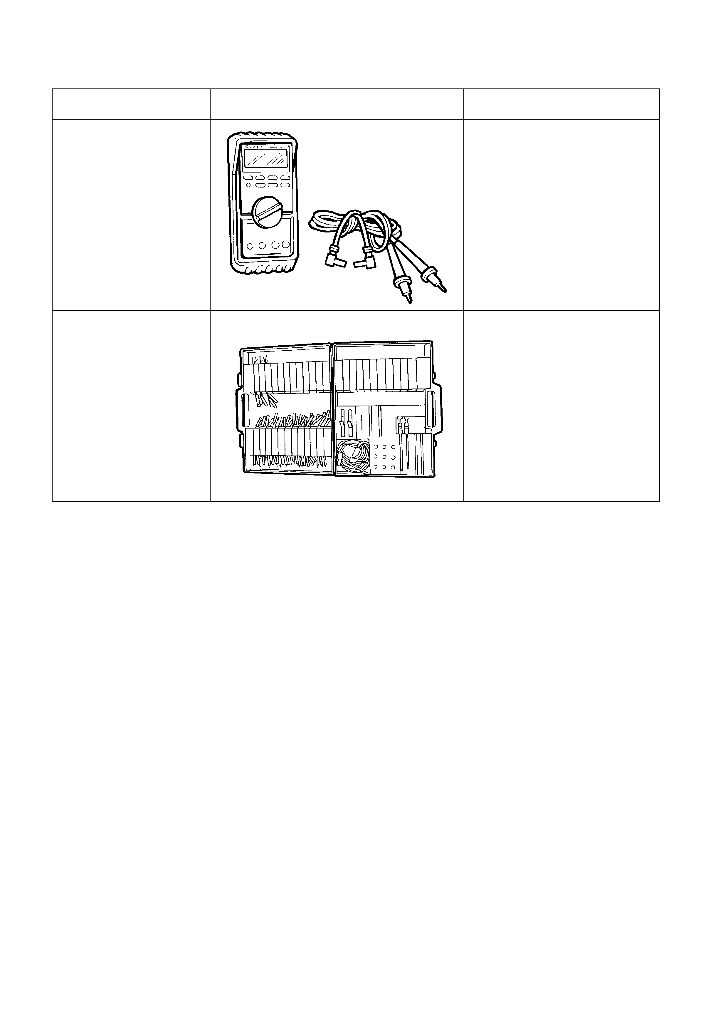
5. SPECIAL TOOLS
TOOL NO. REF IN TEXT TOOL DESCRIPTION COMMENTS
J39200 DIGITAL MULTIMETER TOOL NO. J39200 PRE V IOUSLY
RELEASED, OR USE COMMERCIALLY
AVAILABLE EQUIVALENT. MUST HAVE
10 MOHM INPUT IMPEDANCE
KM-609 CONNECTOR TEST ADAPTOR KIT PREVIOUSLY RELEASED FOR V CAR.
USED IN CONJUNCTION WITH A
MULTIMETER FOR MEASURING
VOLTAGES AND RESISTANCES
WITHOUT DAMAGING WI RI NG
HARNESS CONNECTORS