SECTION 1A8 - HEADLINING AND
REAR END TRIM
IMPORTANT
Before performing any Service Operation or other procedure described in this Section, refer to
Section 00 CAUTIONS AND NOTES for correct workshop practices with regard to safety and/or
property damage.
1. GENERAL DESCRI PTI O N
The headlining used on WH Series vehicles is a one-piece moulded trim.
NOTE: Clean hands are essential when working on the
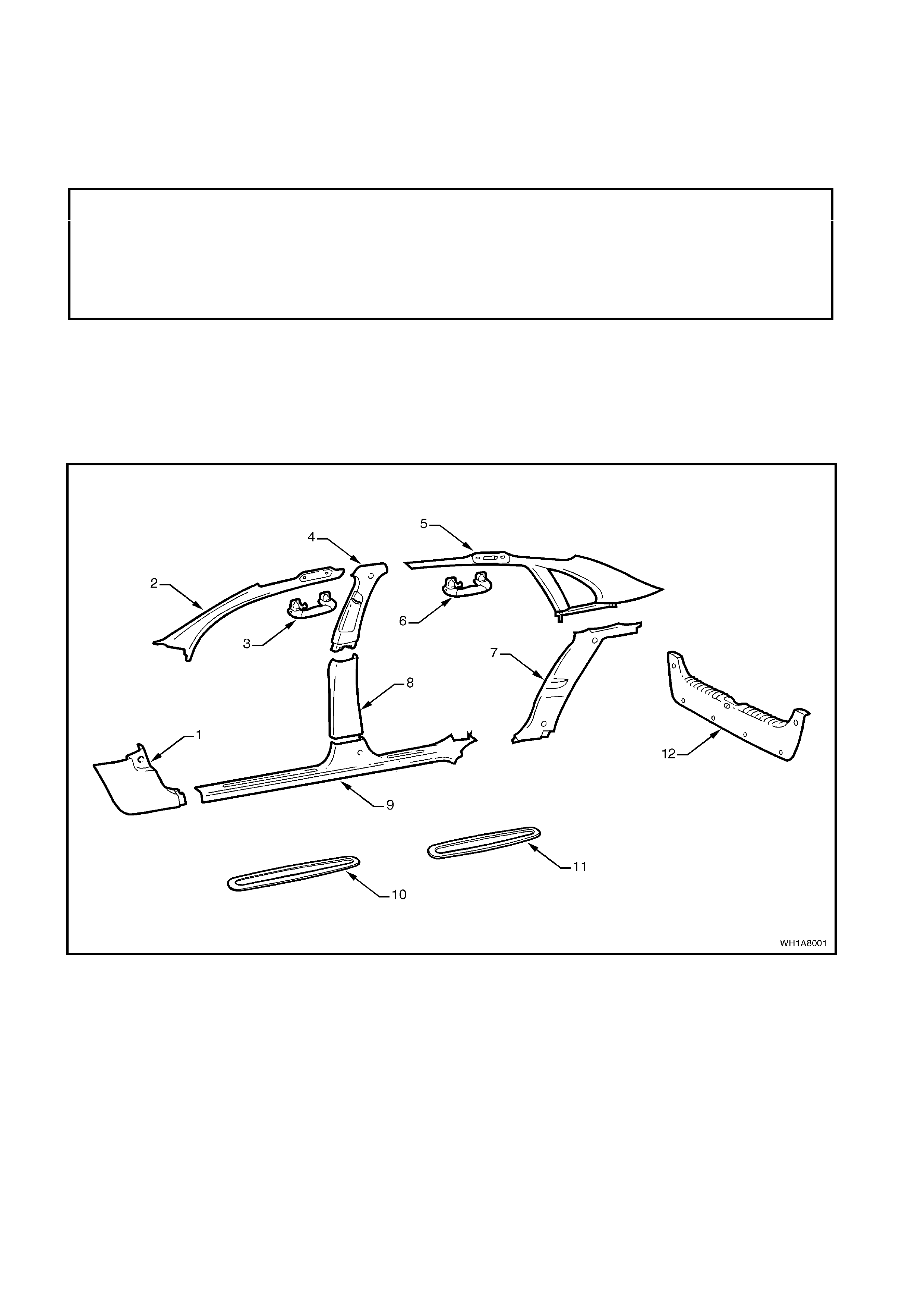
body interior trim. Figure 1A8-1 shows the interior trim components for WH Series Vehicles.
Figure 1A8-1
Legend
1. Shroud lower trim assembly.
2. ‘A’ pillar trim assembly.
3. Front assist grip.
4. Centre pillar upper trim assembly.
5. ‘C’ pillar upper trim assembly.
6. Rear assist grip.
7. ‘C’ pillar lower trim assembly.
8. Centre pillar lower trim assembly.
9. Inner rocker panel cover assembly.
10. Rocker panel front insert.
11. Rocker panel rear insert.
12. Rear compartment crossmember cover.
2. SERVICE OPERATIONS
2.1 HEADLINING ASSEMBLY
REMOVE
1. Disconnect battery ground cable.
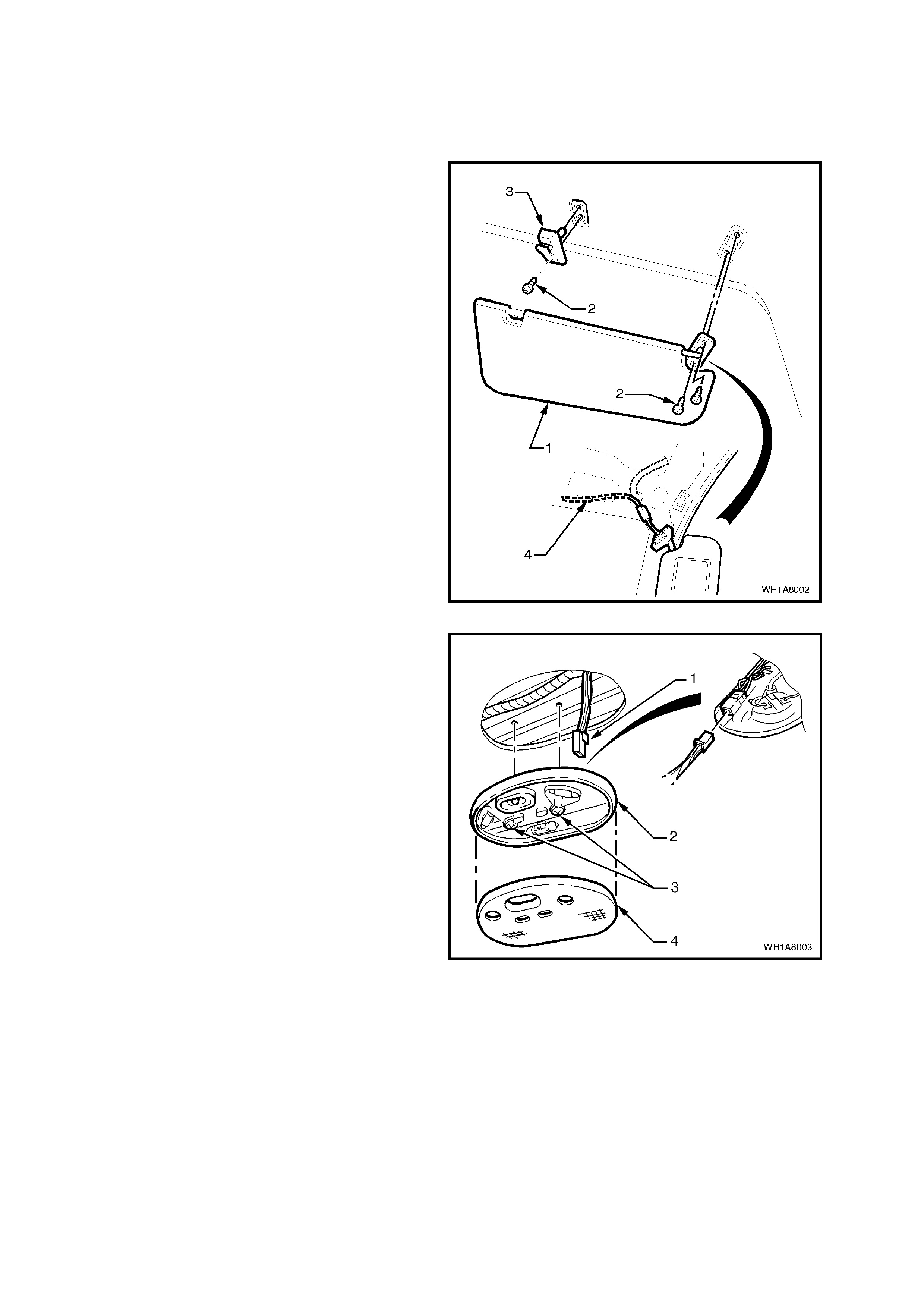
2. Remove the screws (2) securing the interior
sun visors (1), unclip illuminated vanity mirrors
wiring harness (4).
3. Remove the screw securing the interior sun
viso r retainers (3).
NOTE: The illuminated vanity mirrors can be
assisted from their position in the sun visor by
exerting pressure on the rear of the visor.
Figure 1A8-2
4. Prise the roof lam p lens ( 4) from the lamp bas e
(2) and rem ove the securing screws (3) . Lower
the roof lamp and disconnect the wiring
harness connector (1) from the lamp.
Figure 1A8-3
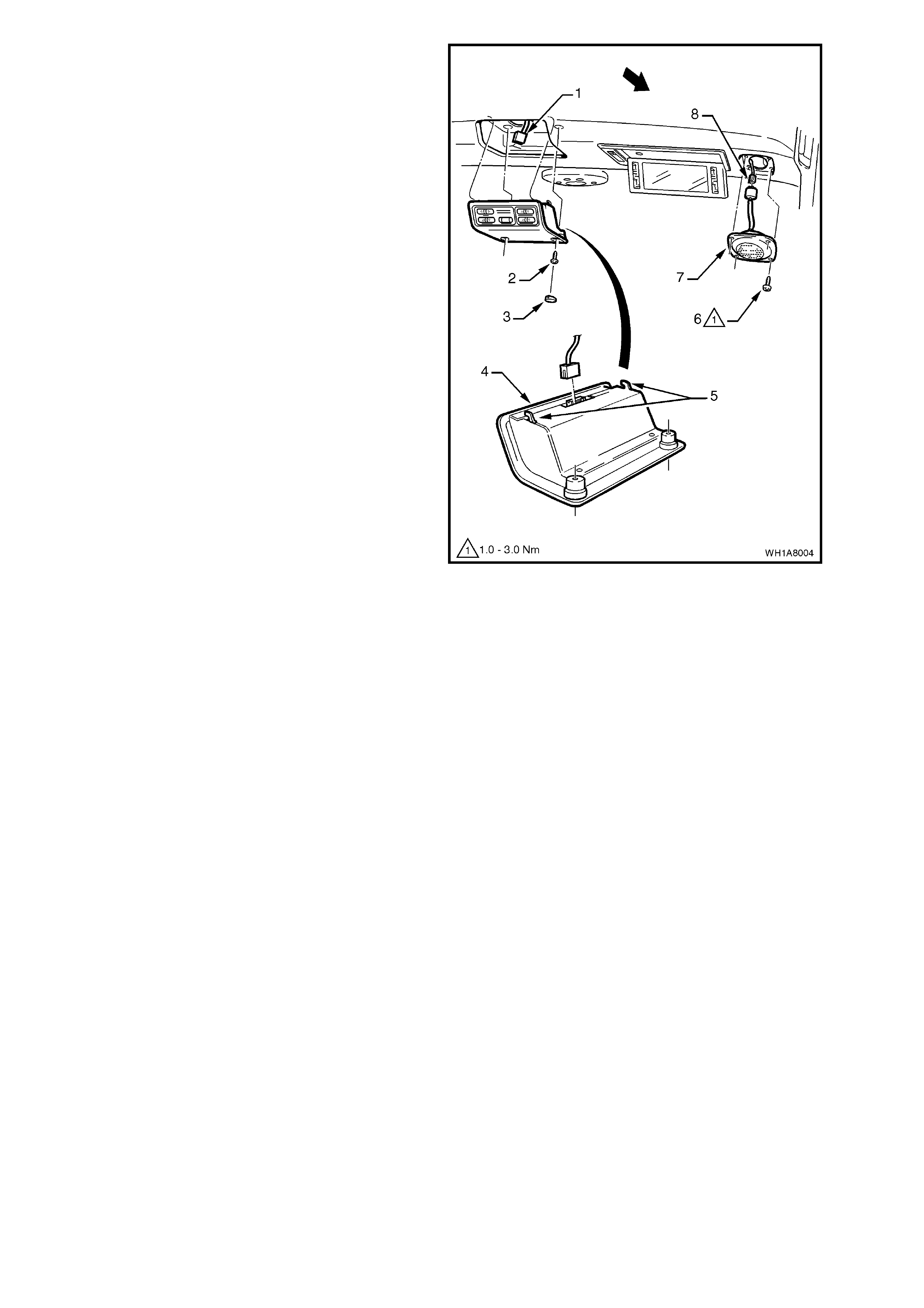
5. Remove blanking plugs (3) and screws (2)
securing the remote control assembly (4) to
headlining support, disengage remote control
locating lugs (5) and lower control disconnect
wiring harness connector (1) and remove
control.
6. Remove the screws (6) securing speakers (7)
to centre support and disconnect wiring
harness connector (8).
7. Remove the screws (2) securing illuminated
vanity mirrors (4), lower mirrors disconnect
wiring harness connector and remove mirrors.
8. Prise reading lamps (3) from their location
disconnect wiring harness connector and
remove reading lamp.
9. Remove screws (2) securing assist grips (1)
and remove assist grip.
NOTE: The illuminated vanity mirrors can be
assisted from their position in the headlining by
exerting pressure on the rear of the mirror
assembly via the roof speaker cavity.
10. From within the cavity left by the remote
control, radio speakers and vanity mirrors
remove the screws securing the headlining
centre support to the roof support.
Figure 1A8-4
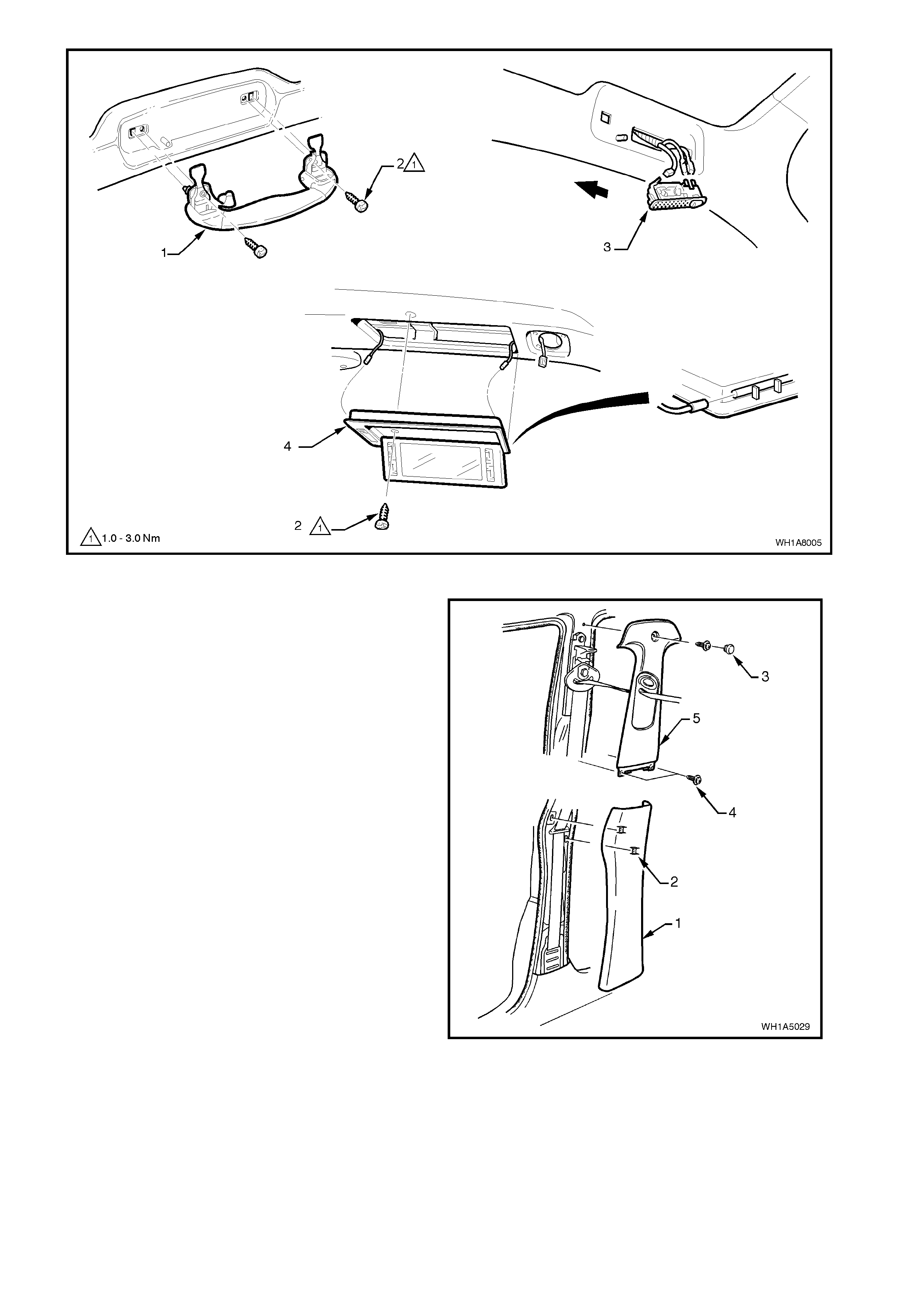
Figure 1A8-5
11. Unclip ‘B’ pillar lower trim (1) and remove
noting position of trim attaching clips (2).
Remove blanking plug (3) and screws (4)
securing ‘B’ pillar upper trim (5) and remove
trim.
Figure 1A8-6
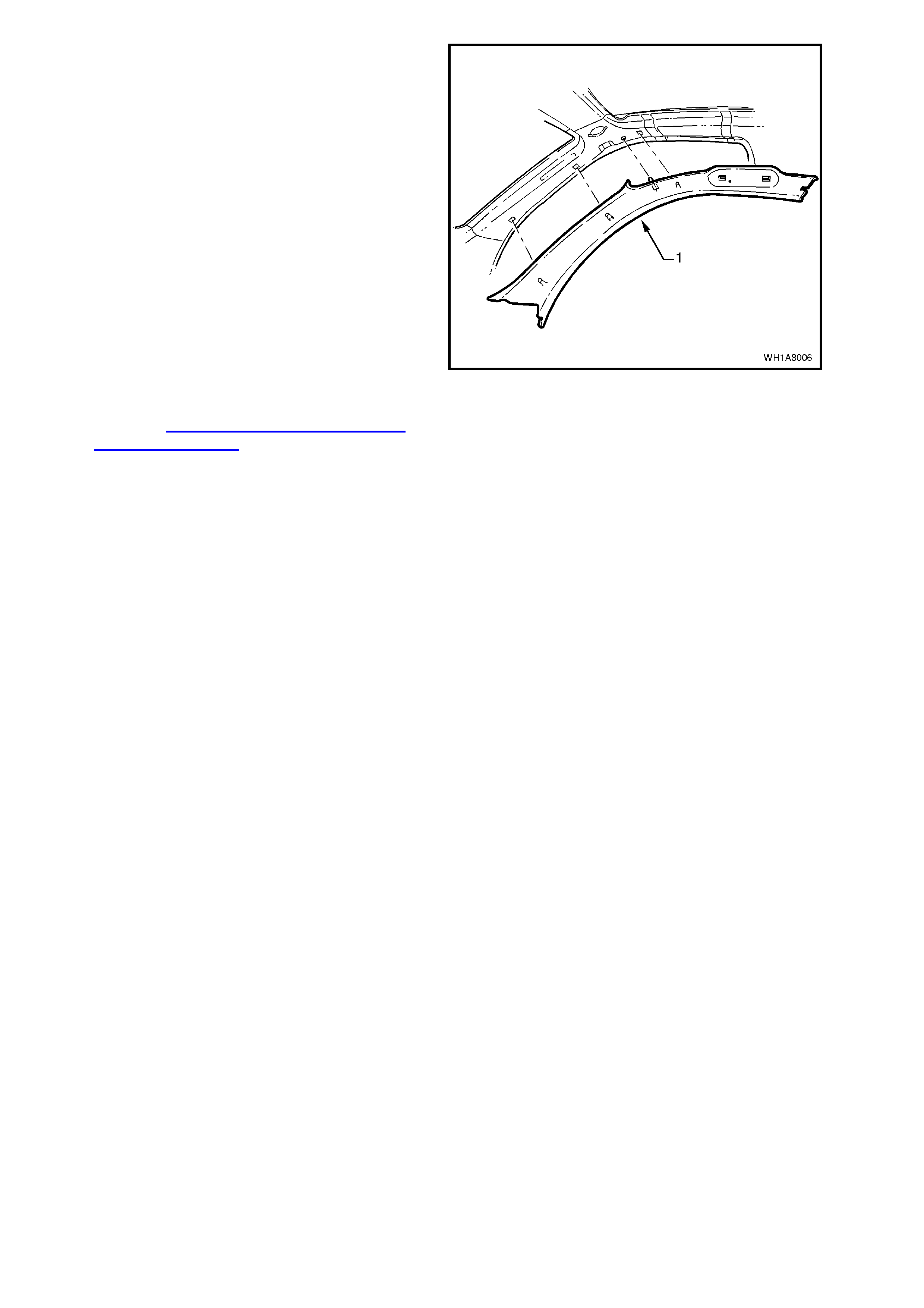
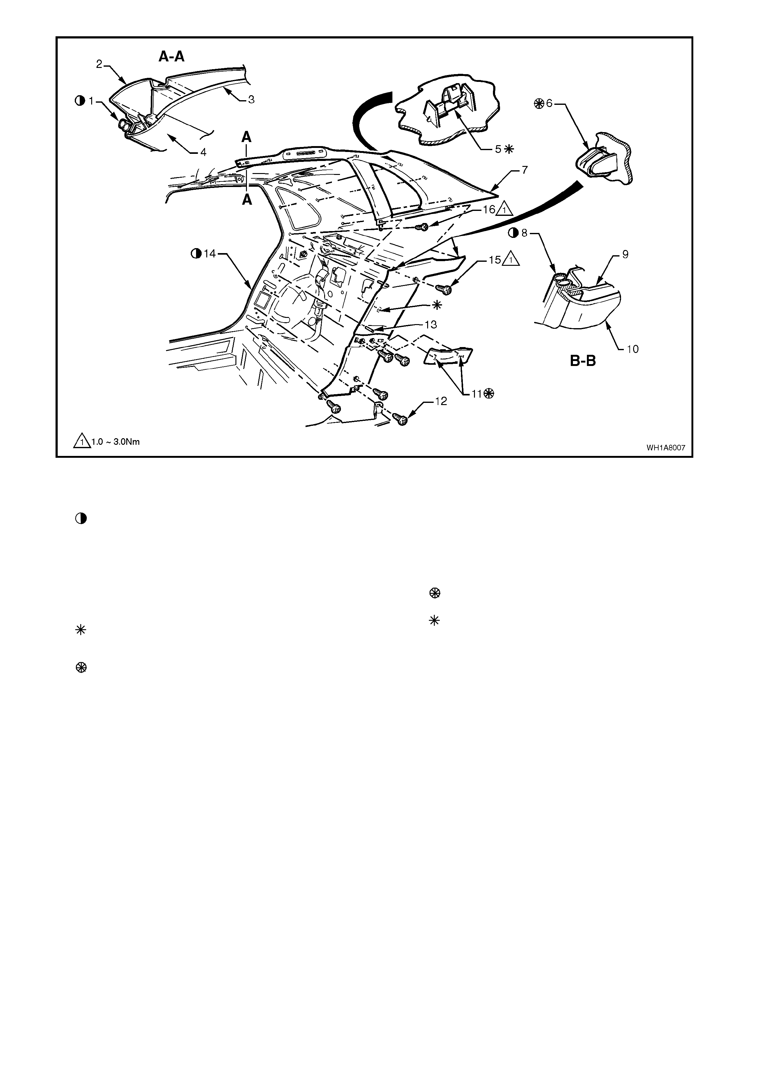
Figure 1A8-8
Legend
1. Door seal.
Door seal must fully engage leading edge of ‘C’ pillar
lower trim, ‘C’ and ‘D’ pillar upper trim. There must be
no gaps or wrinkles.
2. Body sheetmetal.
3. Headlining trim.
4. ‘C’ and ‘D’ pillar upper trim.
5. Clip 7 places upper trim 1 place lower trim
Part of assembly.
6. Clip
Part of assembly.
7. ‘C’ pillar upper trim assembly.
8 Door seal.
9. Body sheetmetal.
10. ‘C’ pillar lower trim.
11. Cap assembly ‘C’ pillar lower.
Part of assembly.
12. Inner rocker panel cover retaining screw.
Part of assembly.
13. Datum pin (2 places).
14. Door seal.
15. Screw (5 places).
15. Open the passenger side front door and
driver’s side rear door.
16. Ease the headlining fr om its pos ition in the r oof
and turn the assem bly so that it can be pass ed
through the passengers side front door,
removing the assembly from the vehicle.
NOTE: It will be necessary to bow the headlining
slightly to pass the assembly through the door
opening.
REINSTALL
Reverse removal operations.
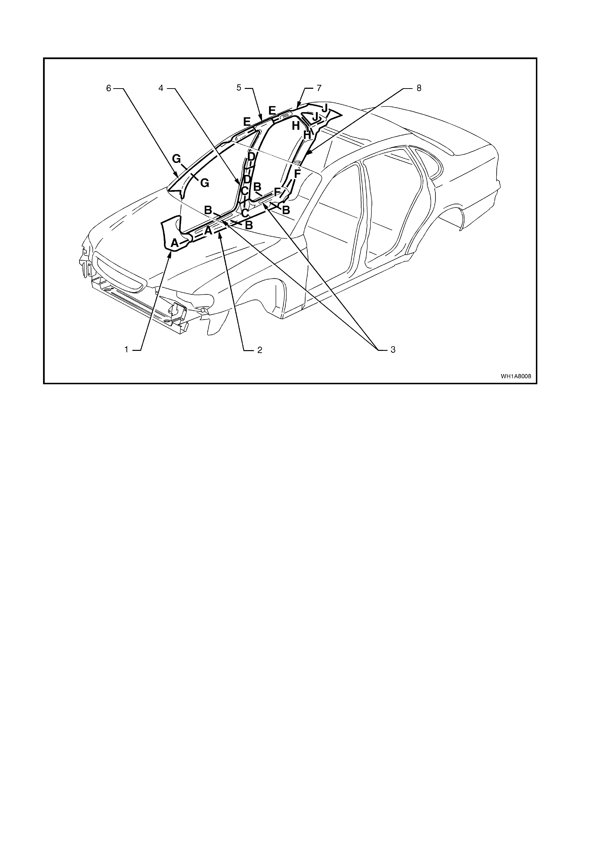
Figure 1A8-9
Legend
1. Shroud lower trim assembly.
2. Inner rocker panel cover.
3. Inner rocker panel cover inserts.
4. Lower ‘B’ pillar trim assembly.
5. Upper ‘B’ pillar trim assembly.
6. ‘A’ pillar trim assembly.
7. ‘C’ pillar trim assembly.
8. ‘C’ pillar lower trim assembly.
For Section views refer Fig. 1A8-10
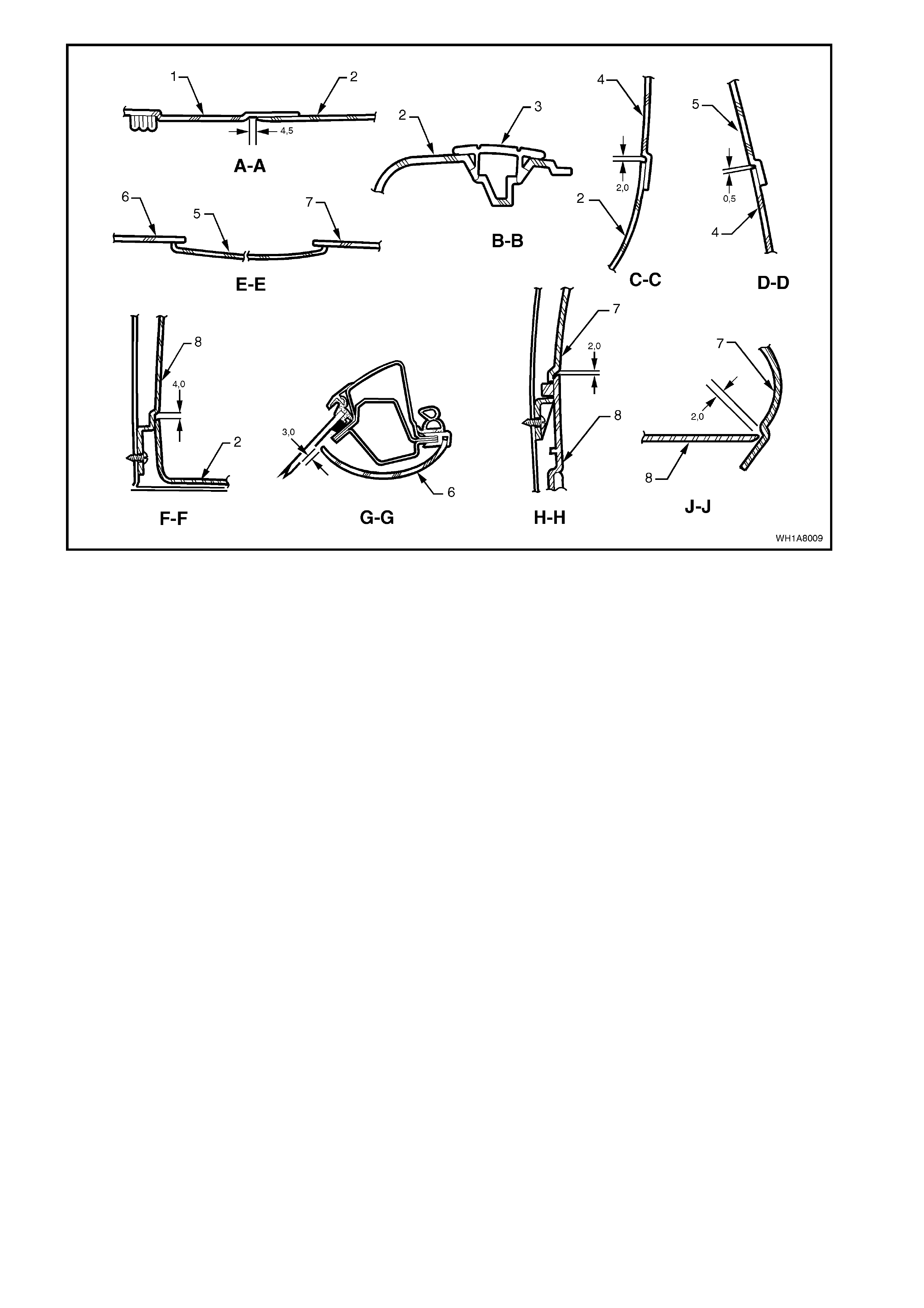
Figure 1A8-10
Legend
1. Shroud lower trim assembly.
2. Inner rocker panel cover.
3. Inner rocker panel cover inserts.
4. Lower ‘B’ pillar trim assembly.
5. Upper ‘B’ pillar trim assembly.
6. ‘A’ pillar trim assembly.
7. ‘C’ pillar trim assembly.
8. ‘C’ pillar lower trim assembly.
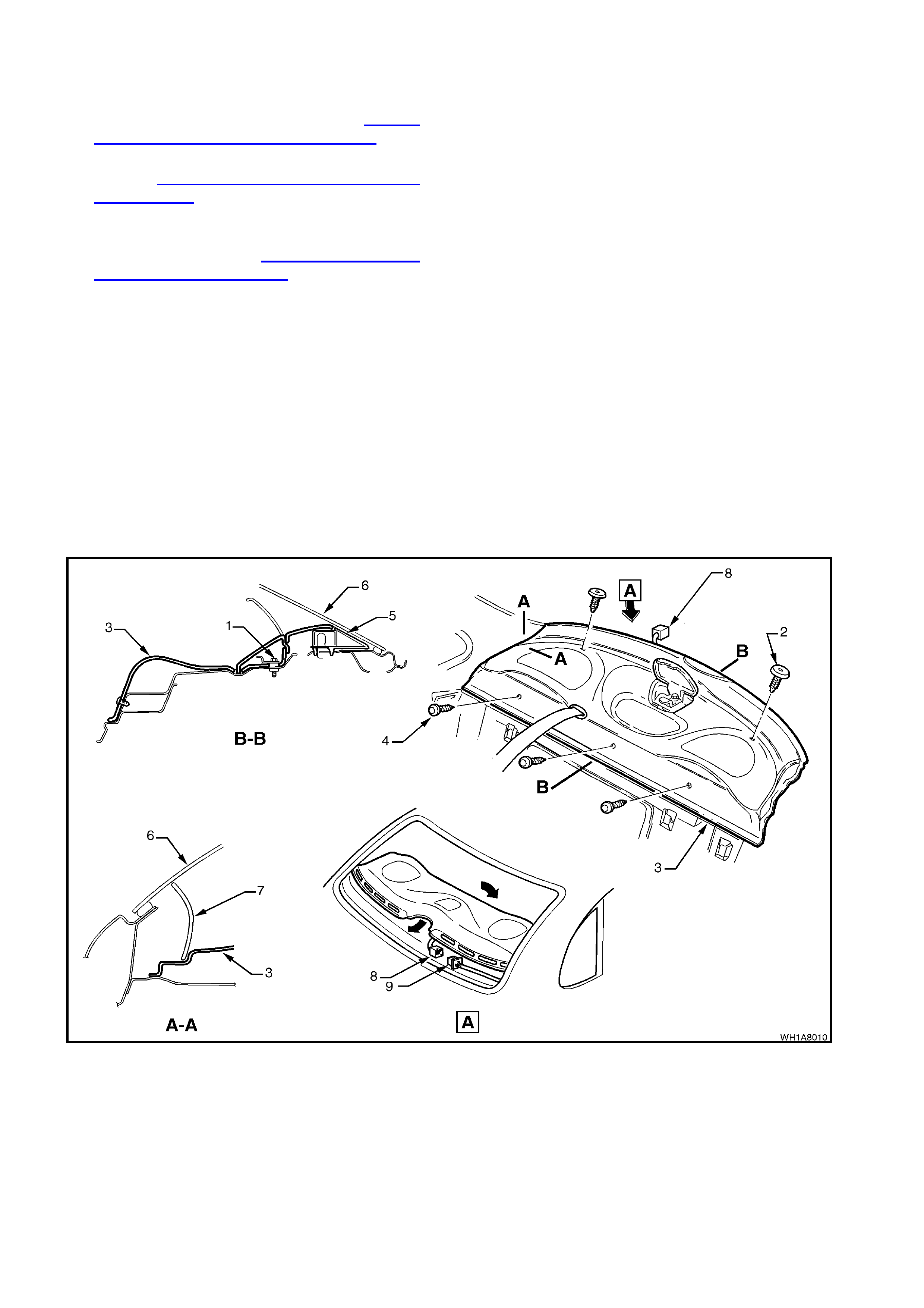
2.2 REAR PARCEL SHELF TRIM
REMOVE
1. Remove rear seat cushion, refer to Section
1A7 SEAT & SEAT BELT ASSEMBLIES.
2. Remove the seat belt lower retaining bolts,
refer to Section 1A7 SEAT & SEAT BELT
ASSEMBLIES.
3. Remove rear seat back, feed outer seat belt
lower anchor, and escutcheon through seat
back opening, refer to Section 1A7 SEAT &
SEAT BELT ASSEMBLIES.
4. Open flap (10) to child restraint fitting and
unbolt child restraint fitting (1).
5. From the rear compartment, carefully unscrew
the alternative child restraint fasteners (4)
securing the trim to the rear parcel shelf.
6. Remo ve seat belt esc utcheon fr om par cel s helf
and feed centre seat belt lower anchor, buckle
and escutcheon through opening in parcel
shelf.
7. Pull front edge of parcel shelf forward,
removing forward firtree fasteners (2).
8. Disconnect rear headphone jack connector (8)
from body harness (9) (Caprice models only)
and remove parcel shelf (3).
Figure 1A8-11
Legend
1. Child restraint mounting bracket.
2. Firtree fastner (2 places).
3. Rear parcel shelf trim.
4. Screw (3 places).
5. High mount stop lamp.
6. Rear window glass.
7. ‘C’ and ‘D’ pillar trim.
8. Headphone jack connector.
9. Body wiring harness connector.
10. Flap.
REINSTALL
Reverse removal operations.
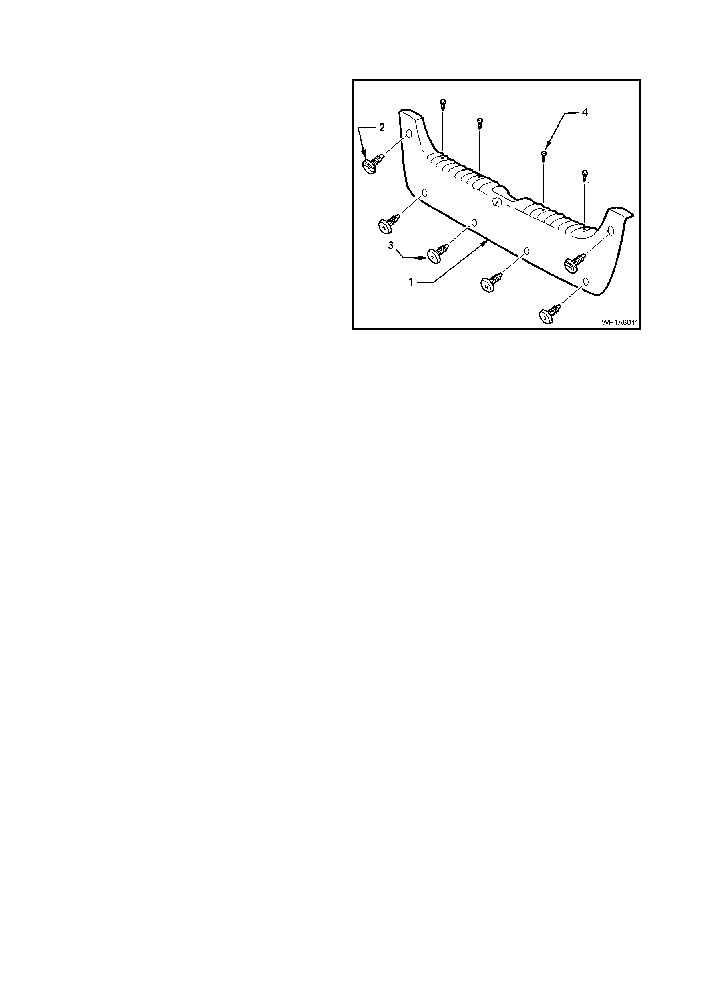
2.3 REAR COMPARTMENT CROSSMEMBER COVE R
REMOVE
1. Remove the screws (4), firtree fastners (3) and
rear compartment luggage net retainers (2)
securing the rear compartment crossmember
cover (1) and remove the cover.
Figure 1A8-12
REINSTALL
Reverse removal operations.