
SECTION 1A9 - EXTERIOR ORNAMENTATION
IMPORTANT
Before performing any Service Operation or other procedure described in this Section, refer to
Section 00 CAUTIONS AND NOTES for correct workshop practices with regard to safety and/or
property damage.
1. GENERAL DESCRI PTI O N
Exterior ornamentation on WH Series Models includes:
• Body side mouldings for both models.
• Various nameplates, emblems and decals depending.
• A windshield moulding cover.
• Door frame-opening mouldings.
• ‘B’ pillar mouldings.
• Roof finisher and side mouldings.
• Rocker panel skirts.
Exterior ornamentation components are secured to the body using various fasteners, double sided tape and
polyurethane adhesive.
Techline
Techline

2. SERVICE OPERATIONS
2.1 SERVICE NOTES
Numerous clips, fasteners, retainers, bushes, screws, nuts and contact adhesives are used to secure the various
exterior ornamentation components to the vehicle body. To locate the service information applicable a to a
particular component, refer to 2.2 PICTORIAL INDEX in this Section.
When removing, handling or installing exterior ornamentation components, the following care should be exercised:
1. Finishers adjacent to the component being removed should be covered with masking tape to prevent damage to
panels and paint work.
2. Removal of adhesive bonded nameplates and emblems is more easily achieved wi th the aid of a heat lamp
positioned adjacent to the part to be removed.
NOTE: Ensure that the heat lamp is not too close to the body, or the heat to intense to adversely affect the paint
finish.
3. Holes in body panels for screws, bolts, clips, etc. that could permit water entry into the body must be adequately
sealed with either a non-hardening sealer or presealed screws, clips, etc.
4. Using a clean cloth, clean the area of body surface where emblems, mouldings, etc. are to be applied with
‘Prepsol’ solvent or equivalent.
5. It is essential that the body temperature of the vehicle be at least 21°C before adhering adhesive bonded
components to the vehicle.
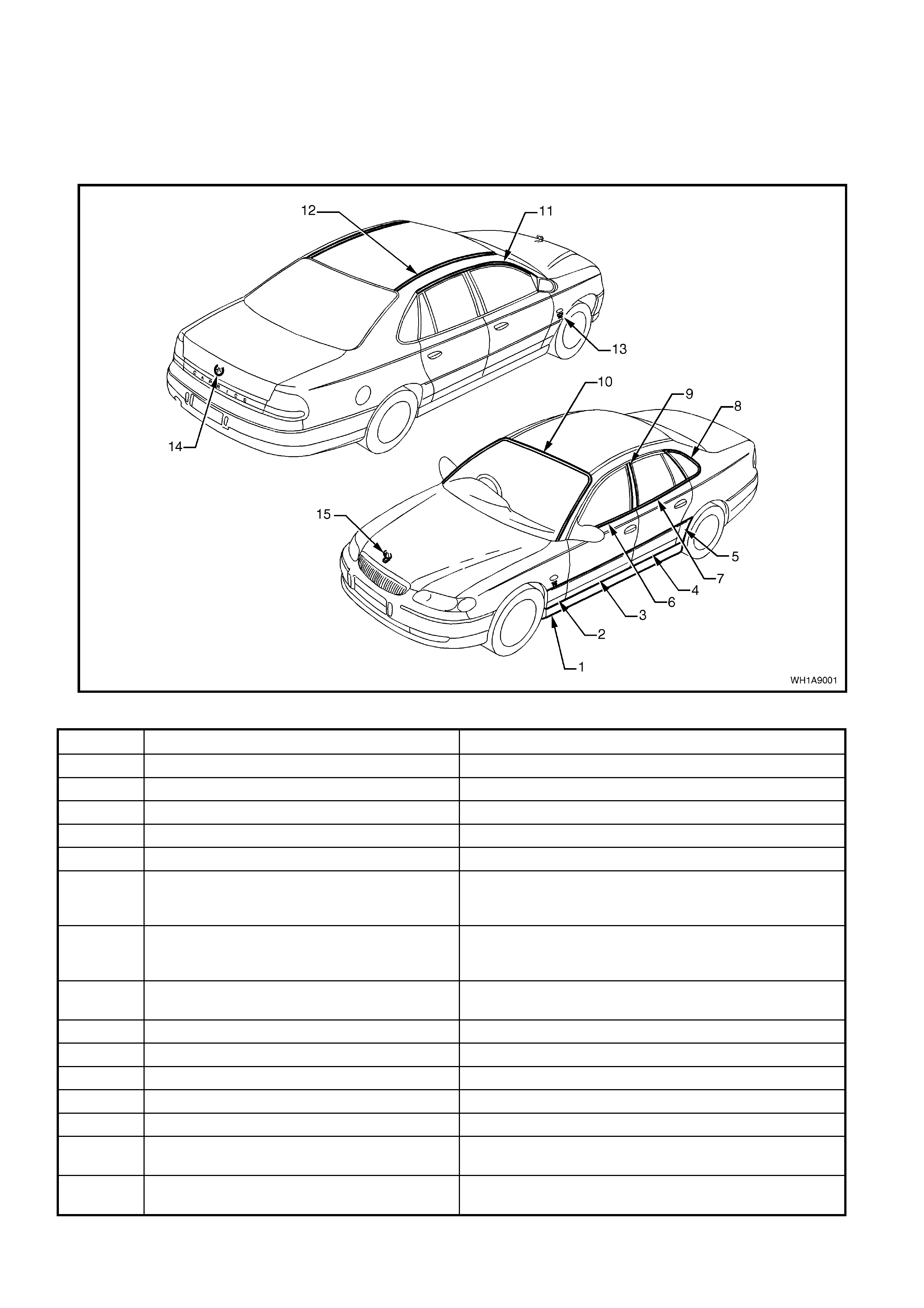
2.2 PICTORIAL INDEX
The following pictograph indexes provide a quick guide to finding the correct service procedure for the applicable
exterior ornamentation component. Within this Section, simply locate the appropriate component in Fig. 1A9-1, and
cross-reference it in the table below the Figure.
STATESMAN AND CAPRICE
Figure 1A9-1
ITEM DESCRIPTION REFERENCE
1 Rocker panel skirt 2.3 ROCKER PANEL SKIRT in this Section
2 Front fender side moulding 2.4 BODY SIDE MOULDINGS in this Section
3 Front door side moulding 2.4 BODY SIDE MOULDINGS in this Section
4 Rear door side moulding 2.4 BODY SIDE MOULDINGS in this Section
5 Rear quarter side moulding 2.4 BODY SIDE MOULDINGS in this Section
6 Front door belt moulding 2.15 FRONT AND REAR DOOR BELT WEATHERSTRIP
AND MOULDING ASSEMBLY in Section 1A5 FRONT AND
REAR DOOR ASSEMBLIES
7 Rear door belt moulding 2.15 FRONT AND REAR DOOR BELT WEATHERSTRIP
AND MOULDING ASSEMBLY in Section 1A5 FRONT AND
REAR DOOR ASSEMBLIES
8 Quarter window frame moulding 3.4 REAR QUARTER WINDOW, Section 1A6
STATIONARY GLASS.
9 ‘B’ pillar moulding 2.5 ‘B’ PILLAR MOULDING in this Section.
10 Windshield moulding cover 2.7 WINDSHIELD MOULDING COVER in this Section
11 Door frame opening moulding 2.8 DOOR FRAME OPENING MOULDING in this Section
12 Roof finisher moulding 2.9 ROOF FINISHER MOULDING - in this Section
13 Engine Badge 2.11 NAME PLATES AND DECALS in this Section
14 Emblem: ‘Lion’ 2.10 ‘LION’ ORNAMENT/EMBLEM – DECK LID in this
Section
15 Ornament: ‘Lion’ 2.10 ‘LION’ ORNAMENT/ EMBLEM – ENGINE HOOD in
this Section
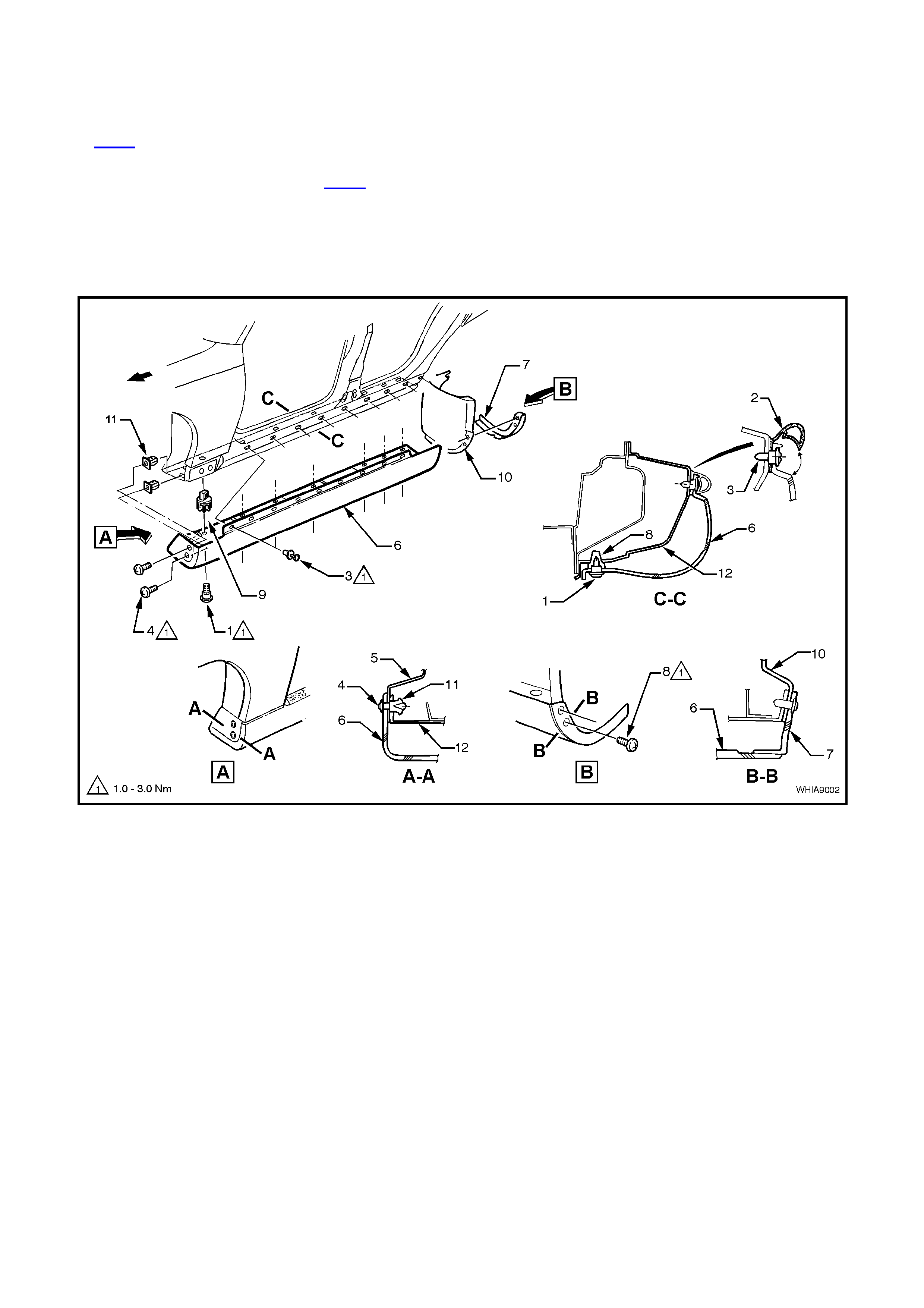
2.3 ROCKER P ANEL SKIRT
REMOVE
1. From under vehicle, remove the seven rocker panel skirt lower retaining screws (1), refer to View C-C in Fig.
1A9-2.
2. Lift up lip of rocker panel skirt weatherstrip (2) to gain access to the nine retaining scrivets (3) and remove
scrivets, refer to View C-C in Fig. 1A9-2.
3. Remove the two screws (4) securing the rocker panel front skirt to the fender liner.
4. Slide rocker panel front skirt forward until it is free from the rocker panel rear skirt, and remove rocker panel
front skirt.
5. Remove the two screws (8) securing the rocker panel rear skirt (7) to the body and remove rocker panel rear
skirt.
Figure 1A9-2
Legend
1. Screw (7 places).
2. Rocker panel skirt weatherstrip assembly.
3. Scrivet (9 places).
4. Screw (2 places).
5. Front fender liner.
6. Rocker panel front skirt.
7. Rocker panel rear skirt.
8. Screw (2 places).
9. Nutsert (7 places).
10. Rear wheelhouse liner.
11. Nut.
12. Door opening frame.
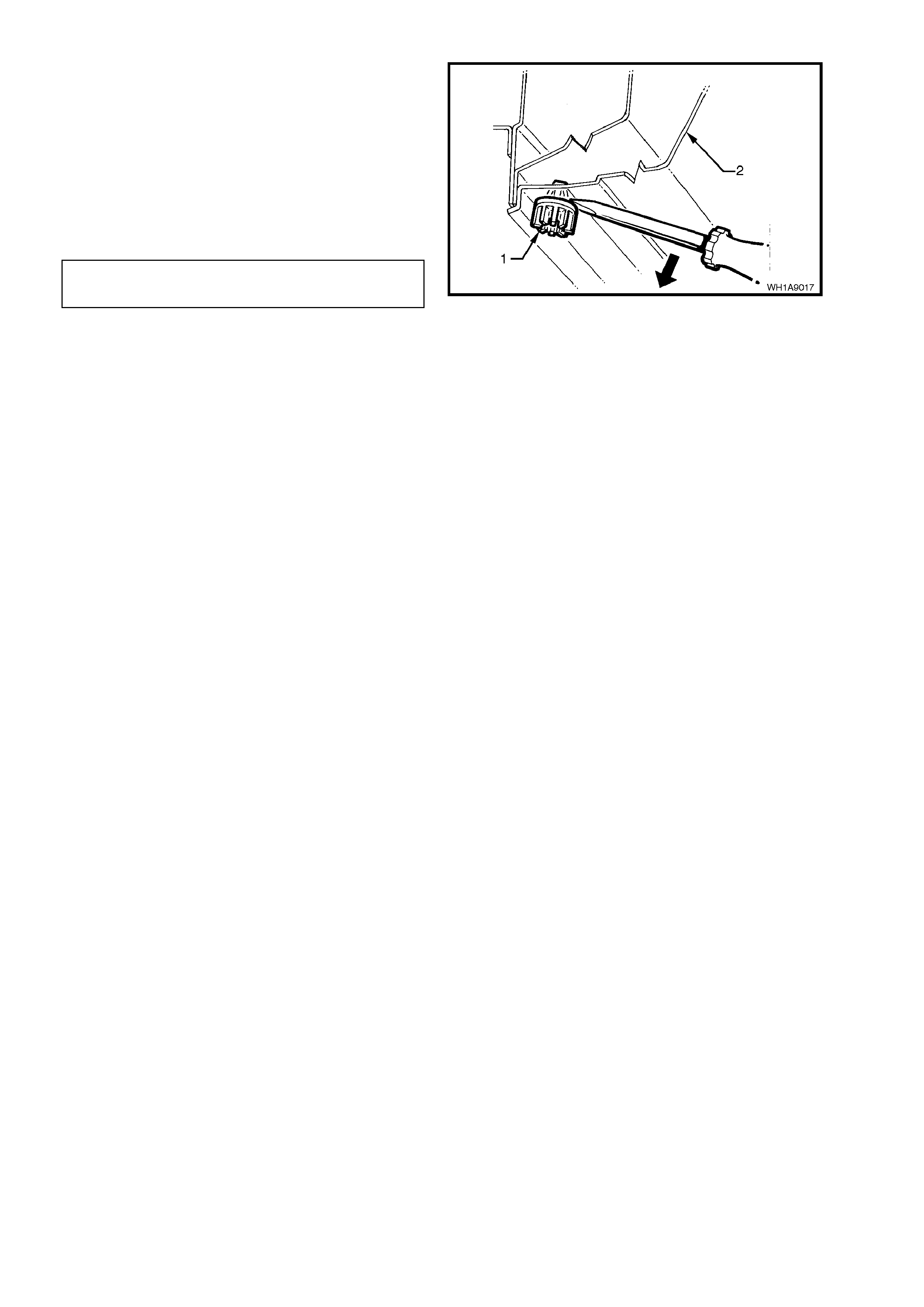
6. If necessary, remove the seven nutserts (1) by
gently levering nutsert out from the body (2),
taking care not to damage paintwork.
REINSTALL
Reinstallation of the rocker panel front and rear
skirts is the reverse of the removal operation,
ensuring that all fasteners are tightened to the
correct torque specification.
ROCKER PANEL SKIRT
RETAI NING SCREWS 1 - 3 Nm
TORQUE SPECIFI CATION Figure 1A9-3
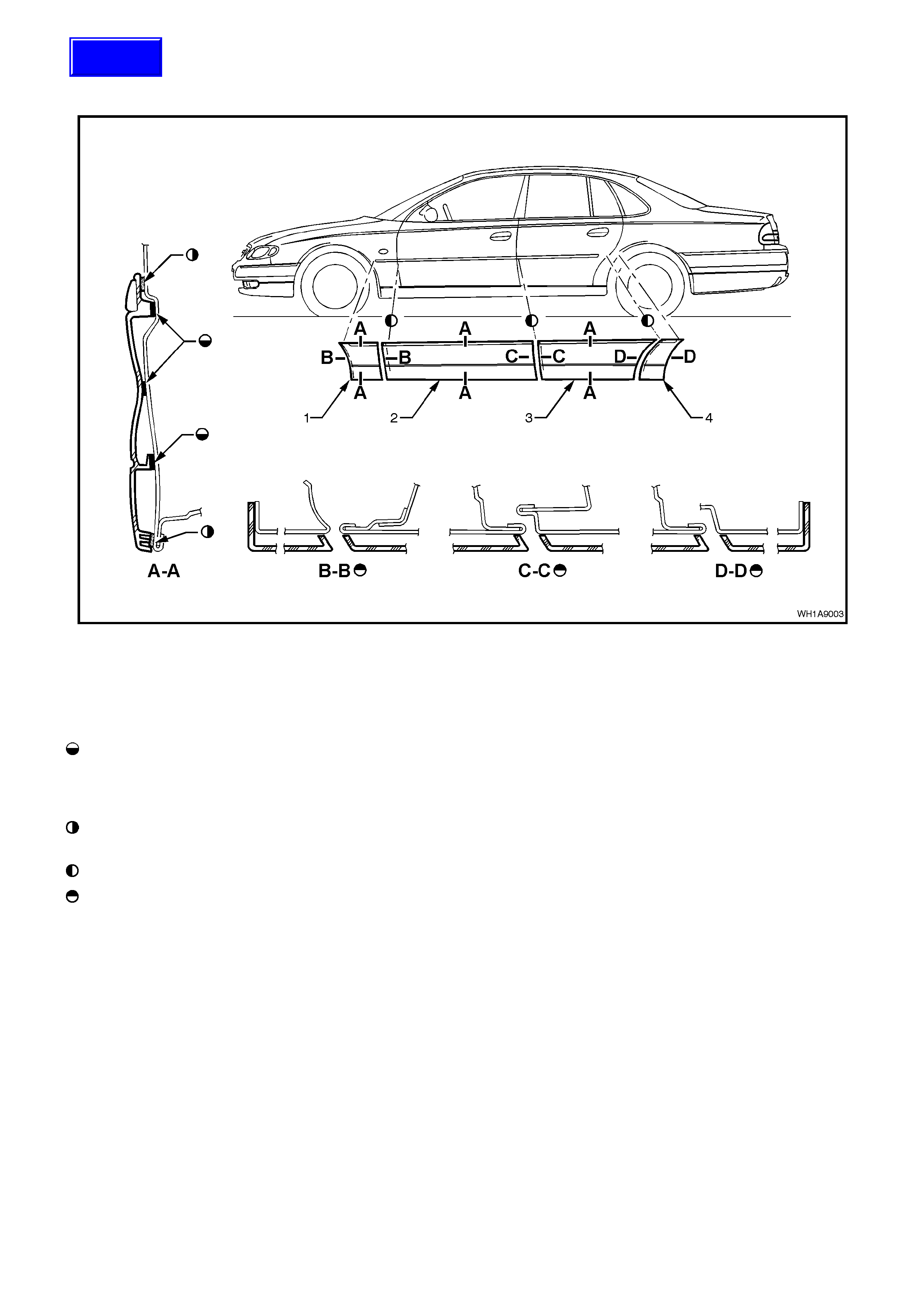
2.4 BODY SIDE MOULDINGS
STATESMAN AND CAPRICE
Figure 1A9-4
Legend
1. Front fender side moulding.
2. Front door side moulding. 3. Rear door side moulding.
4. Rear quarter side moulding.
Service Notes:
Apply a 3.0 mm diameter bead of polyurethane
adhesive suc h as ‘Expandite Betas eal 554.02’ or
equivalent, to Holden Specification HN 1890
over entire length of mouldings.
Double sided adhesive foam tape (part of
moulding assembly).
Top edge of mouldings to be in line.
Front edge of door mouldings to be 1mm back
from door edge.
Techline
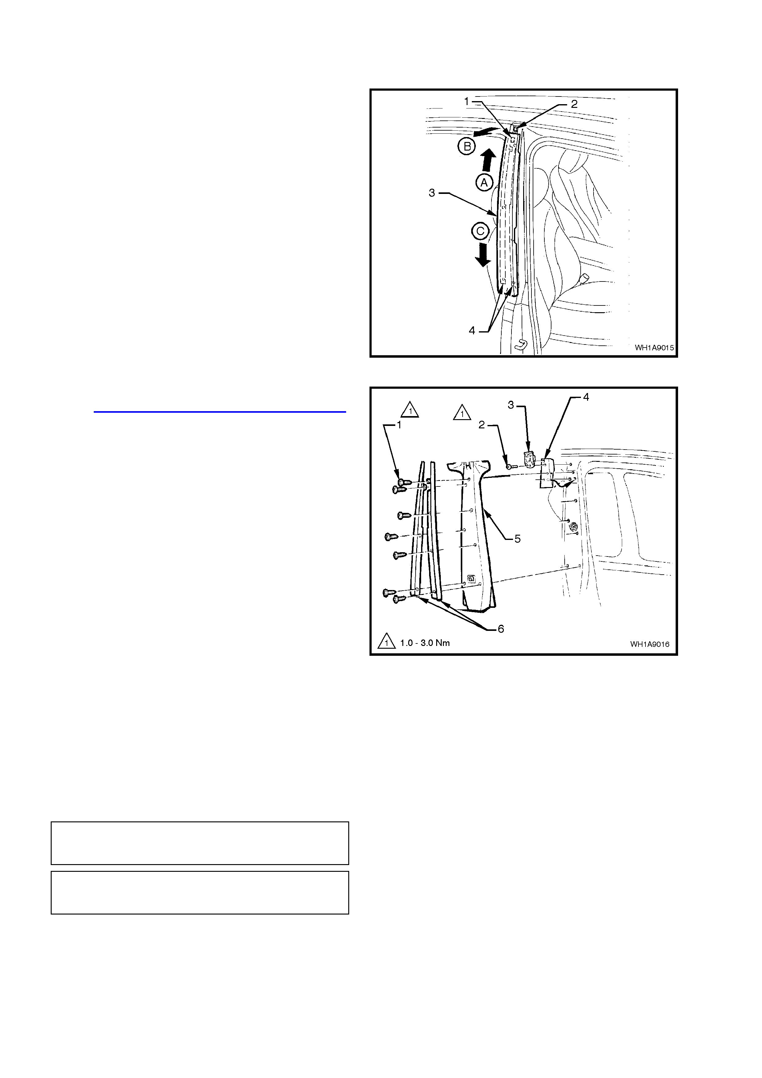
2.5 ‘B’ PILLAR MOULDINGS
REMOVE
1. Open front and rear door on relevant side of
vehicle.
2. To release the outer moulding (3) from the
retaining clip (2), push the outer moulding up by
hand slightly (A) while gently levering top of
moulding out and away from ‘B’ pillar (B).
3. With top of ‘B’ pillar retaining catc h (1) re leased
from retaining clip, hold top of moulding out and
slide moulding down weatherstrip retaining
tracks (C) until moulding rests on rear door
hinge assembly.
4. Jiggle outer moulding until it becomes free from
weatherstrip retaining tracks (4), and remove
outer moulding.
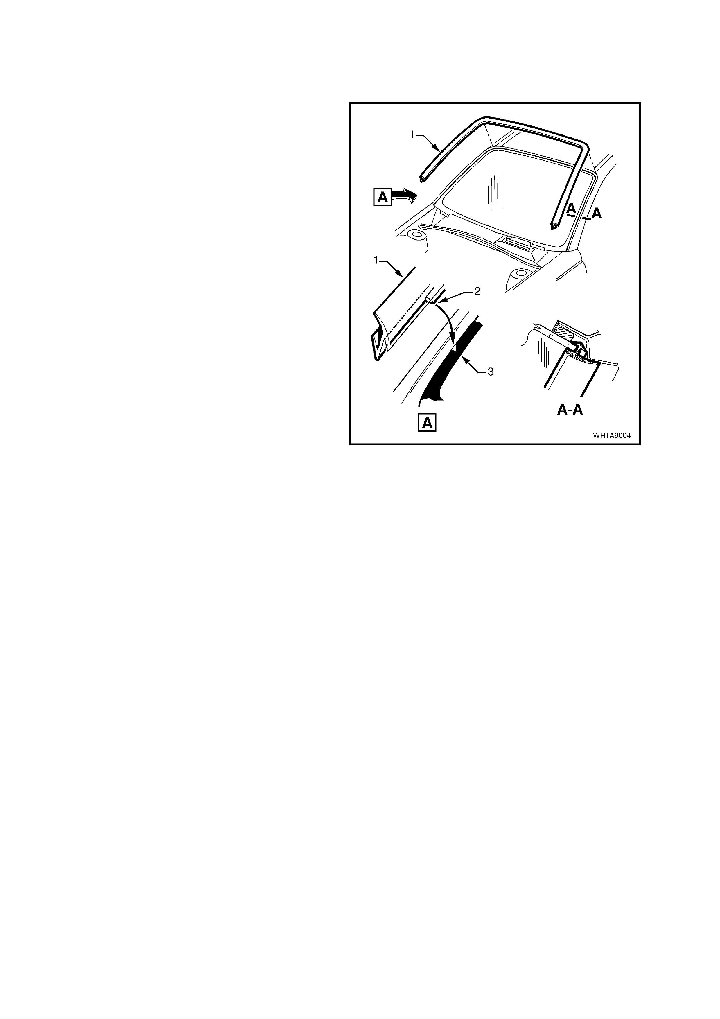
Figure 1A9-5
5. Remove the doorframe opening moulding, refer
to 2.8 DOOR FRAME OPENING MOULDING
in this Section.
6. Remove the seven screws (1curing the ‘B’ pillar
weatherstrips retaining tracks (6) to the ‘B’ pillar
and remove weatherstrip assemblies.
7. Remove inner cover (5) by pulling cover away
from ‘B’ pillar.
8. Remove the screw (2) securing the moulding
retaining clip (3) and mounting (4) to the ‘B’
pillar and remove retaining clip and mounting.
Figure 1A9-6
REINSTALL
Reinstallation of the ‘B’ pillar moulding is the
reverse of the removal procedure, noting the
following:
1. Ensure the inner cover is seated correctly,
under door opening weatherstrips.
2. Ensure all fasteners are tightened to the
correct torque specification.
‘B’ PILLAR MOULDING RETAINING
CLIP SECURING SCREW 1 - 3 Nm
TORQUE SPECIFICATION
‘B’ PILLAR WEATHERSTRIP
ASSEMBLY SECURING SCREW 1 - 3 Nm
TORQUE SPECIFICATION
3. Slide the outer moulding up and press it in at
the top so that it engages into the retaining clip.

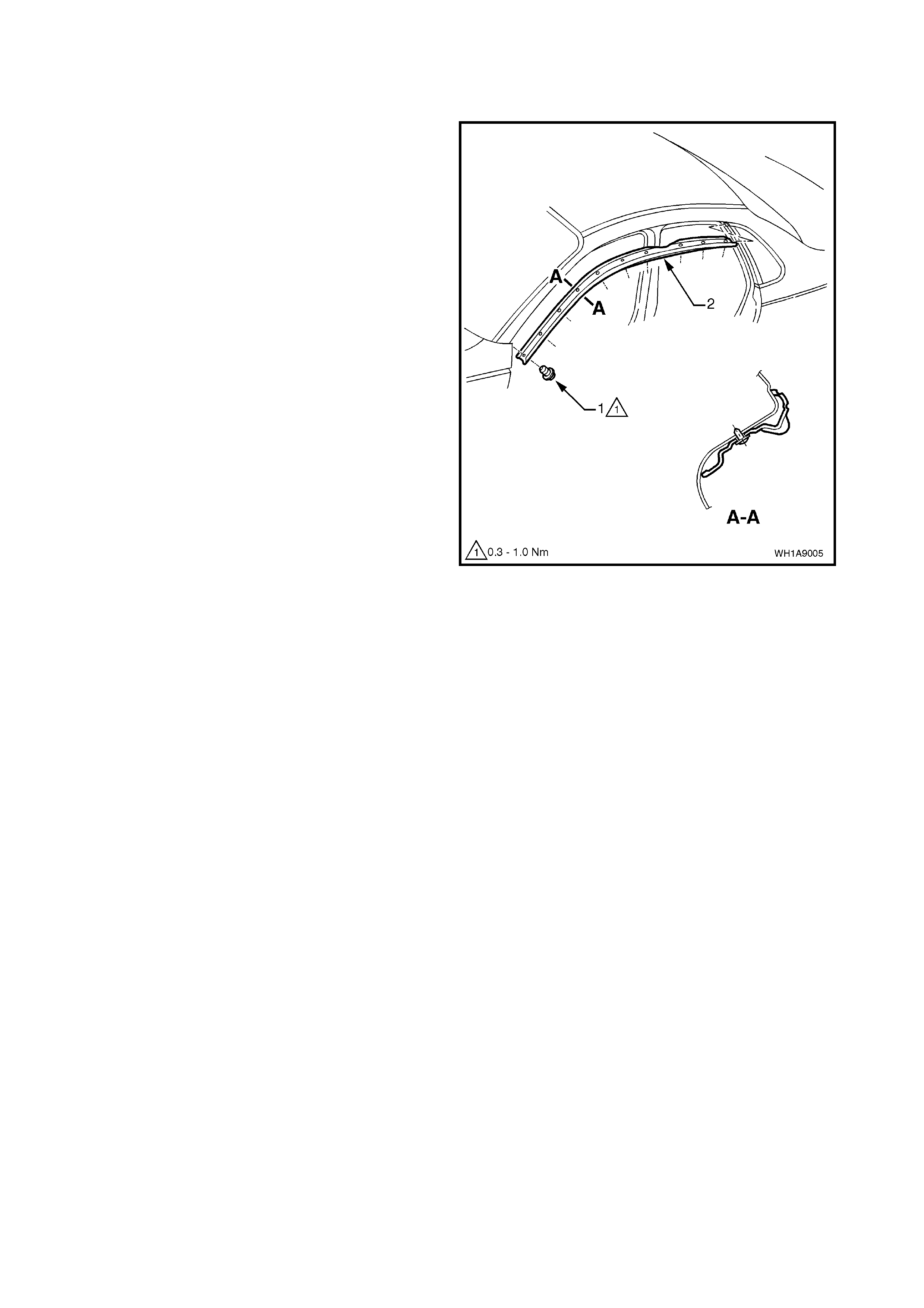
2.7 WINDSHIELD MOULDING COVER
REMOVE
Starting at lower corner of the windshield moulding
cover (1), gently pry windshield moulding cover
from windshield opening.
REINSTALL
1. Insert drivers side lower end of windshield
moulding c over (1) loos ely behind top of guard.
Begin installing windshield moulding cover at
drivers side lower corner of windshield. Align
datum mark on windshield (3) with datum
section on moulding cover (2).
2. Insert passenger side lower end of windshield
moulding cover loosely behind top of guard.
Align datum mark on windshield with datum
section on moulding cover. Attach moulding to
passenger side windshield, working from lower
corner to upper corner of windshield.
3. Install upper portion of windshield moulding
cover, work ing from driver side upper c orner to
passenger side upper corner.
Figure 1A9-7
2.8 DOOR FRAME OPENING MOULDING
REMOVE
1. Open front and rear door on relevant side of
vehicle.
2. Remove the screws (1) securing door frame
opening moulding (2) to body (11 places) and
remove moulding.
Figure 1A9-8
REINSTALL
Reinstallation is the reverse of the removal procedure.
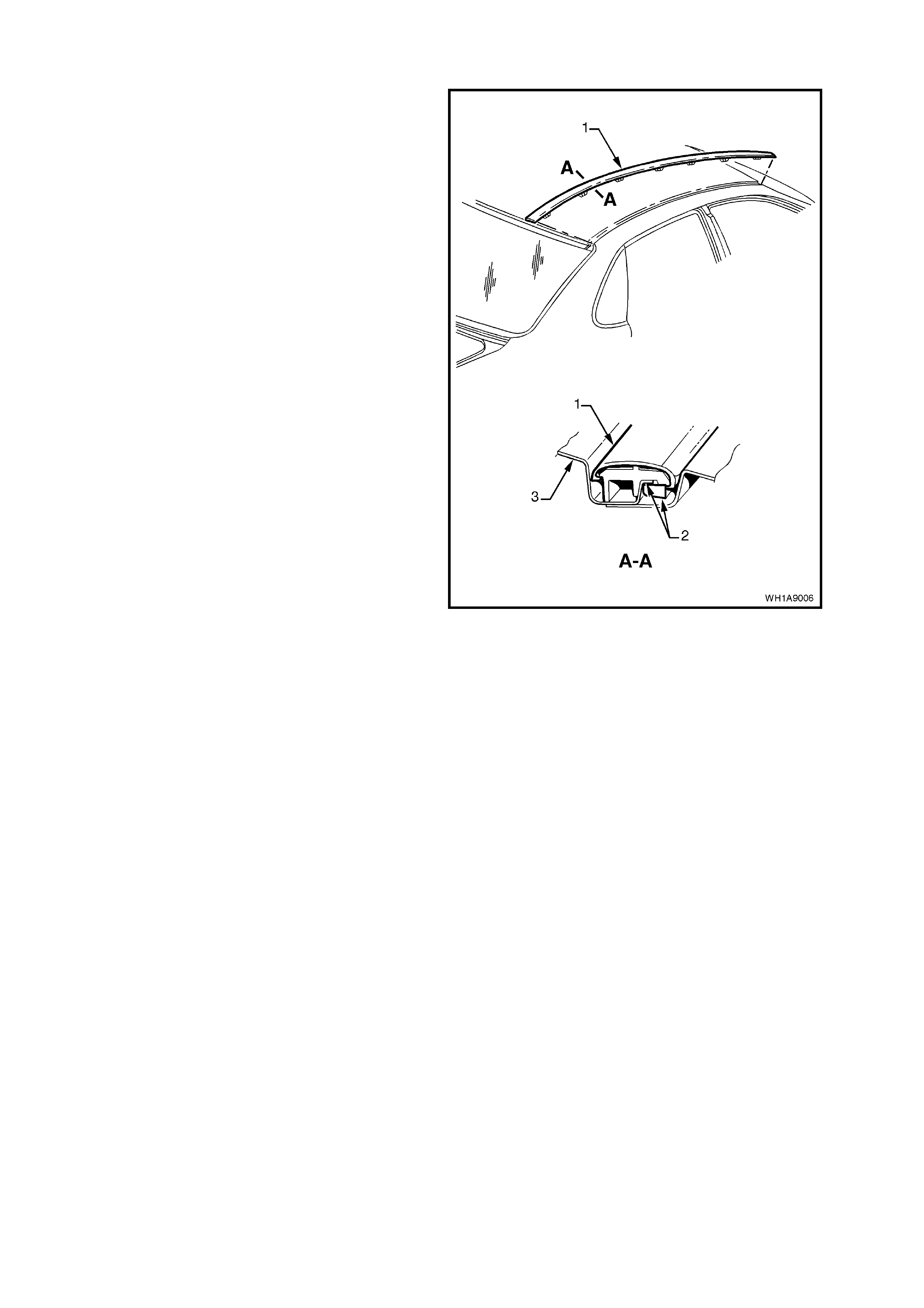
2.9 ROOF FINISHER MOULDING
REMOVE
1. Using a screw driver with a clean shop rag to
prevent paint work damage, pry the front of the
roof f inis her moulding (1) out of the r oof c hannel
between the top of the windscreen to the top of
the rear window.
2. Slide the roof finisher moulding out of the side
moulding retaining channel.
REINSTALL
1. Engage roof finisher moulding over side
moulding and slide along until roof finisher
moulding is in line with back window moulding
2. Engage roof finisher moulding clips along roof
until roof finisher m oulding s its f lush agains t the
roof (3), ensure clips engage under roof panel
flange.
NOTE: The roof finisher moulding must be installed
under the windshield moulding cover. Figure 1A9-9
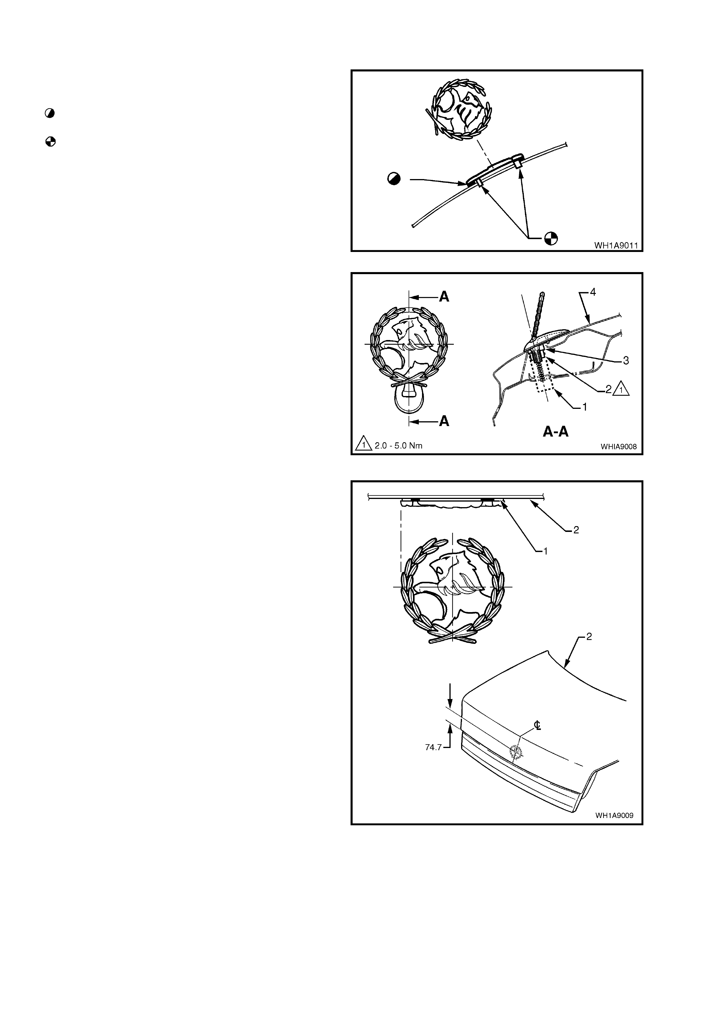
2.10 ‘LION’ EMBLEM/ORNAMENT
ENGINE HOOD-STATESMAN
Service notes
Before installation, remove release paper from
adhesive foam tape.
After removing release paper from adhesive
foam tape, ensure there is a band of adhesive
foam tape around base of locating pins.
Figure 1A9-10
ENGINE HOOD - CAPRICE
Service notes
Install ornament in existing holes at centre line of
engine hood outer panel.
Legend
1. Nut runner
2. Retaining nut
3. Hood ornament spacer.
4. Engine hood outer panel.
Figure 1A9-11
DECK LID
Service notes
NOTE 1: Before installation, remove release paper
from adhesive foam tape.
Dimensions shown in mm.
Legend
1. Adhesive foam tape.
2. Deck lid.
Figure 1A9-12
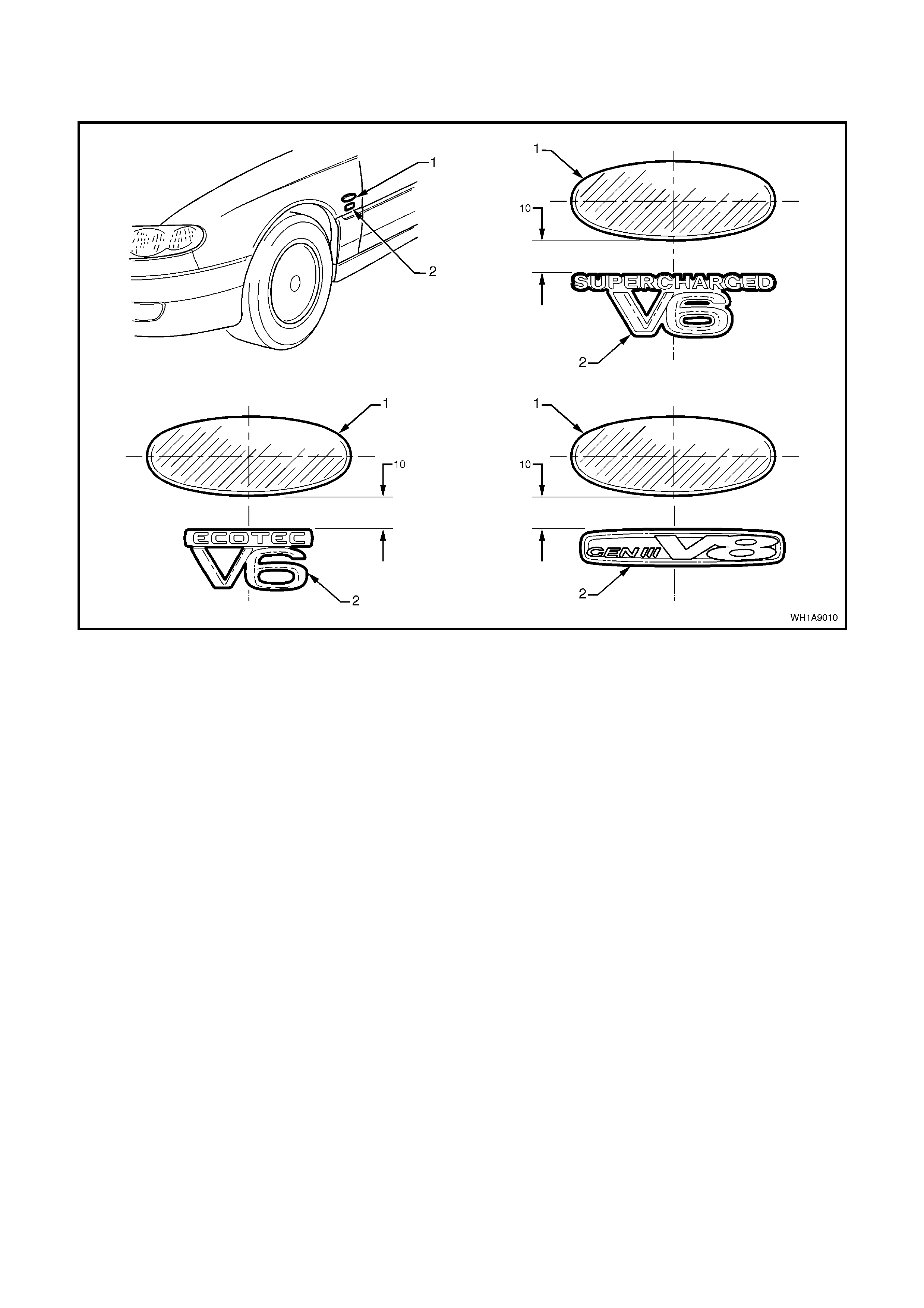
2. 11 NAME PLATES AND DECALS
STATESMAN AND CAPRICE
Figure 1A9-13
Legend
1. Side repeater lamp. 2. Engine badge.
Dimensions shown in mm.

3. TORQUE WRENCH SPECIFI CATIONS
Nm
Rocker Panel Skirt Retaining Screw..................................... 1 - 3
‘B’ Pillar Moulding Retaining Clip Retaining Screw............... 1 - 3
‘B’ Pillar Weatherstrip Assembly Securing Screw................. 1 - 3
Door Frame Opening Moulding Securing Screw.................. 0.3 - 1.0