
SECTION 1B - SHEET METAL
IMPORTANT
Before performing any Service Operation or other procedure described in this Section, refer to
Section 00 CAUTIONS AND NOTES for correct workshop practices with regard to safety and/or
property damage.
1. GENERAL I NFORMATI ON
WH Series front end sheet metal components consist of engine hood, front fender and front end panel, to which
homofocal headlamps are mounted. The engine hood assembly is hinged at the rear end and is supported in the
open position by two gas struts attached to the engine hood inner panel and to the front fender inner panel.
The hood lock release lever mounted beneath the right-hand side of the instrument panel, controls the hood lock
release spring. The engine hood when released from the locked position engages in a secondary safety catch which
can be released by inserting fingers beneath the leading edge of the engine hood.
A fuel filler door remote control is located between the driver's seat and sill panel on all models. The control
releases the fuel filler door when the lever is moved up.
2. SERVICE OPERATIONS
2.1 FRONT FENDER ASSEMBLY
REMOVE
1. Remove the front bumper bar assembly (refer to Section 1D BUMPER BARS).
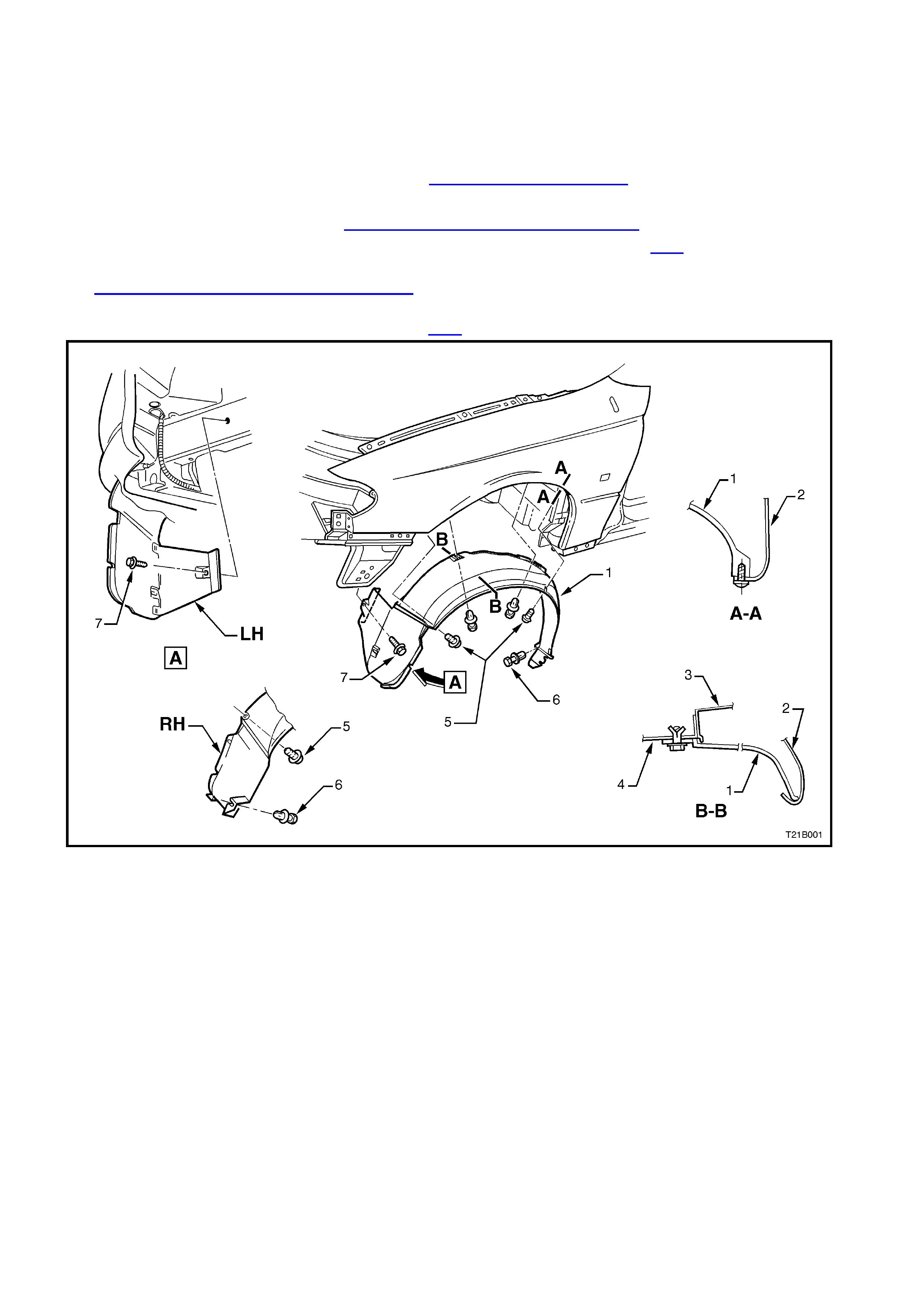
2. Remove the front fender liner (1), from the side which fender is to be removed refer Fig. 1B-1.
3. Remove the radio antenna. Refer to Section 12D RADIO/CASSETTE PLAYER.
4. Remove screws securing fender to the front end assembly illustrated in refer Fig. 1B-2.
5. Disconnect gas struts from engine hood, rem ove s crews s ecuring gas s trut m ounting brac ket to f ender, ref er to
2.2 ENGINE HOOD GAS STRUT ASSEMBLY.
6. Remove the screw and washer assemblies securing the fender upper and lower sections to the front-end
assembly and engine inner skirt panel, refer Fig. 1B-2, remove the fender.
Figure 1B-1
Legend
1. Front fender liner.
2. Front fender.
3. Fender reinforcement.
4. Front wheelhouse.
5. Screw - fender liner retaining
(3 places).
6. Rivet - fender liner retaining
(3 places).
7. Screw - fender liner retaining
(1 place, left hand side only).
REINSTALL
Reinstallation is the reverse of removal procedures.
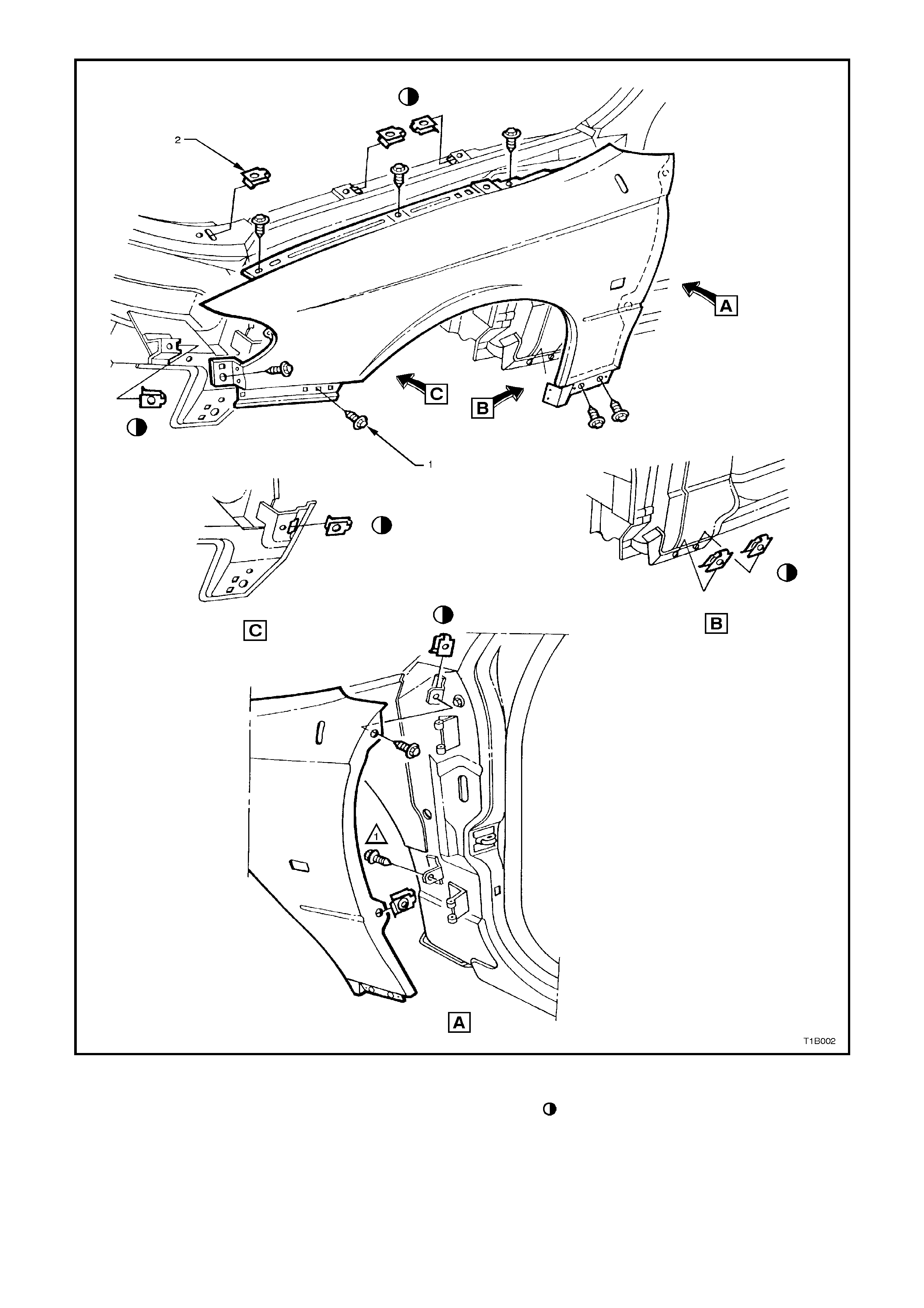
Figure 1B-2
Legend
1. Screw (9 places R/L). 2. Speed nut( 9 places R/L). Fender to body rework.
A. Drill out speed nut to 9.6 mm Dia.
B. Install insert.
C. Retain with screw and washer
assembly.
2.2 ENGINE HOOD GAS STRUT ASSEMBLY
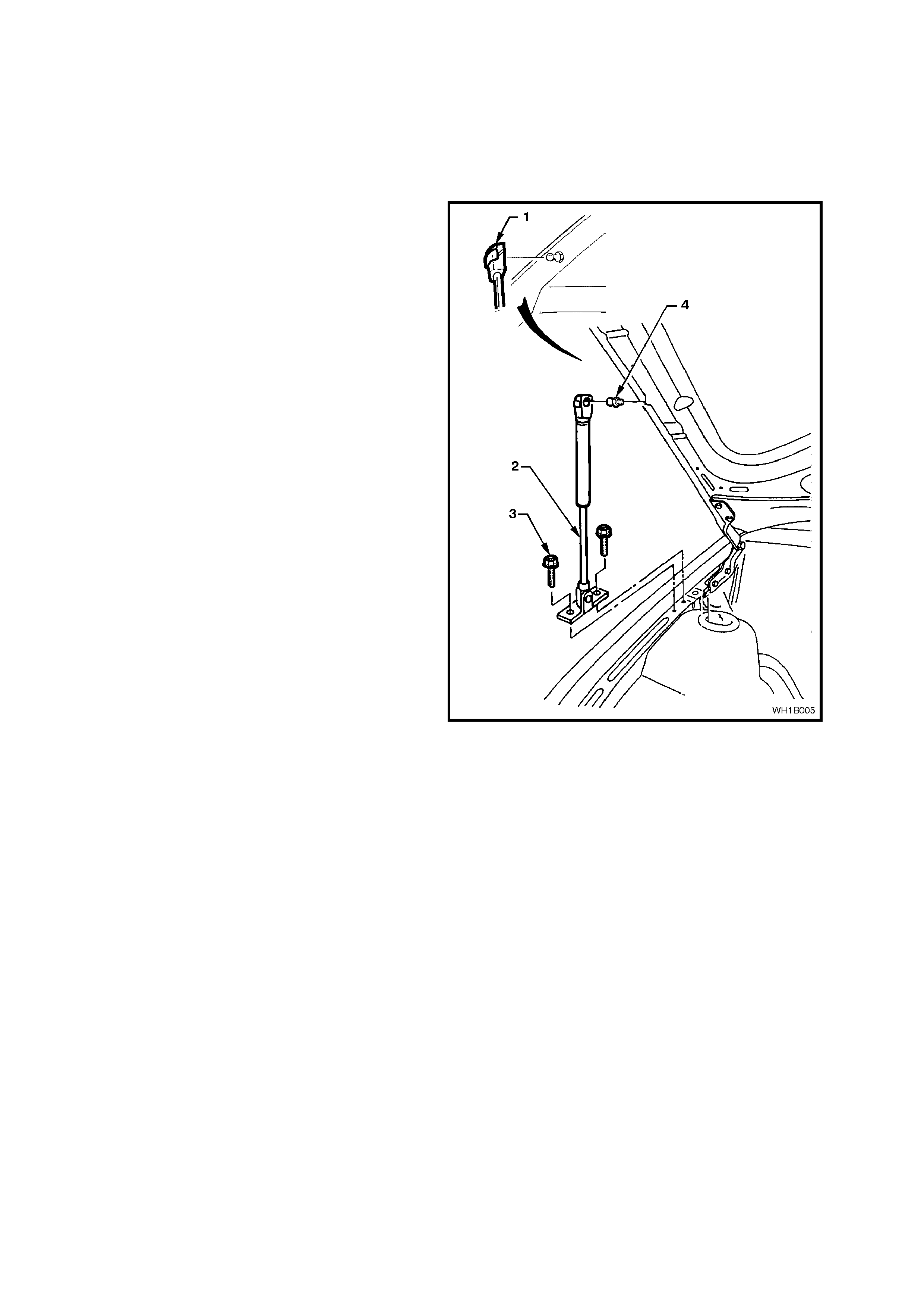
CAUTION: Gas struts are filled with
compressed gases and therefore should never
be subjected to extreme heat, pressure or
physical damage as personal injury can result.
REMOVE
1. With the engine hood adequately supported,
remove the clip (1) securing the engine hood
gas support strut (2) to the ball stud (4).
2. Disconnect the strut from the engine hood ball
stud.
3. Remove gas strut lower mount attaching
screws (3) and remove gas strut (l).
Figure 1B-3
REINSTALL
Reverse removal operations.

2.3 ENGINE HOOD ASSEMBLY
REMOVE
1. With the engine hood raised and supported,
disconnect windshield washer tube and engine
hood gas strut assemblies from the engine
hood ball studs, r efer 2.2 ENGINE HOOD GAS
STRUT ASSEMBLY in this Section.
2. With the engine hood adequately supported
and with the aid of an assistant, remove the
screw from the hinges (refer to Fig. 1B-4, on
the following page), removing the assembly.
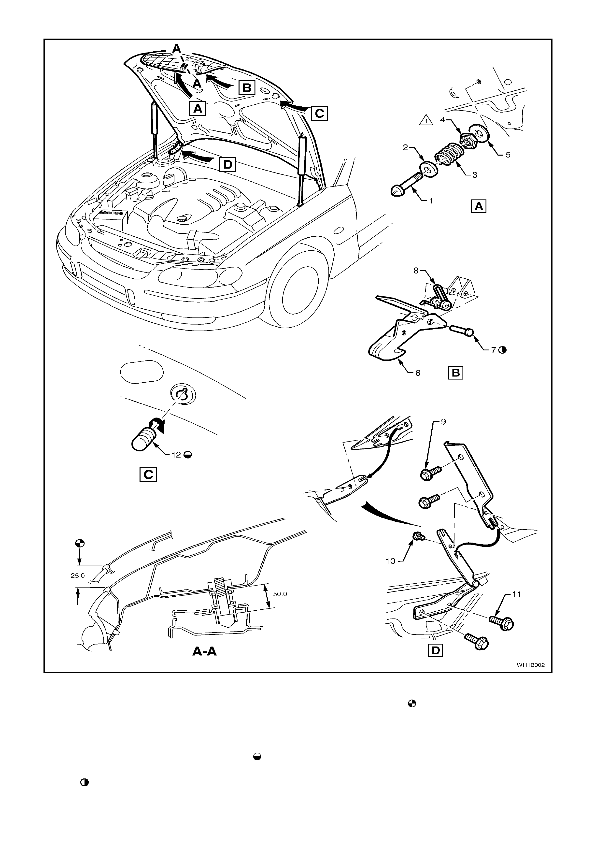
Figure 1B-4
Legend
1. Pilot pin.
2. Retainer.
3. Spring.
4. Nut.
5. Washer.
6. Hood lock catch.
7. Rivet Lubricate with HN
1225.
8. Spring.
9. Screw (2 Places).
10. Screw (1 Place).
11. Screw (2 Places).
12. Buffer (2 Places). Set fully
in. Then adjusted as required
to achieve alignment of
panels.
Pilot pin set to nominal. Then
pilot pin & buffer adjusted to
achieve front end clearance
and alignment for grille
clearance to front bumper
facia. Lubricate head of pilot
pin with HN 1225.

REINSTALL
Reverse removal operations.
ADJUST
When adjusting the engine hood assembly, uniform
spacing and alignment between the engine hood
and adjacent parts is important.
Slotted holes in the hinge arms provide horizontal
adjustment, whilst slots in the hinge support
mounting to shroud side provide vertical
adjustment for the rear end of the engine hood.
Vertical adjustment for the front end of the engine
hood is achieved by adjustm ent of the pilot pin and
hood lock nut in conjunction with the hood buffers
located on the fr ont of the engine hood inner panel
(refer view C in Fig.1B-4, refer previous page).

2.4 PILOT PIN, HOOD LOCK
REMOVE
1. Raise the engine hood assembly.
2. Slacken off the hood pilot pin lock nut, then,
still retaining the nut, unscrew the pilot pin in an
anti-clockwise direction, refer view A in
Fig. 1B-4.
REINSTALL
Reverse removal operations.
ADJUST
W ith the pilot pin lock nut loose sc rew the pin in or
out to achieve the engine hood clearance as
specified in Fig. 1B- 4, tighten the locking nut.


2.6 ENGINE HOOD RELEASE CABLE ASSEMBLY
REMOVE
1. Raise the engine hood assembly.
2. Remove radiator front shroud refer the
Section 6B-1 – ENGINE COOLING of the VT
Series I Service Information.
3. Depress the hood lock release spring and
disengage the nipple at the front end of the
release cable from the release spring,
illustrated in Fig. 1B-5, on the following page.
4. Disengage clip securing cable assembly to
front end panel assembly, refer to Fig. 1B-5.
5. From inside the vehicle, slide the cable,
bracket and lever assembly illustrated in Fig.
1B-5, from the right hand shroud panel lower,
rearwards; then pull the complete assembly
into the vehicle.
REINSTALL
Reverse removal operations.
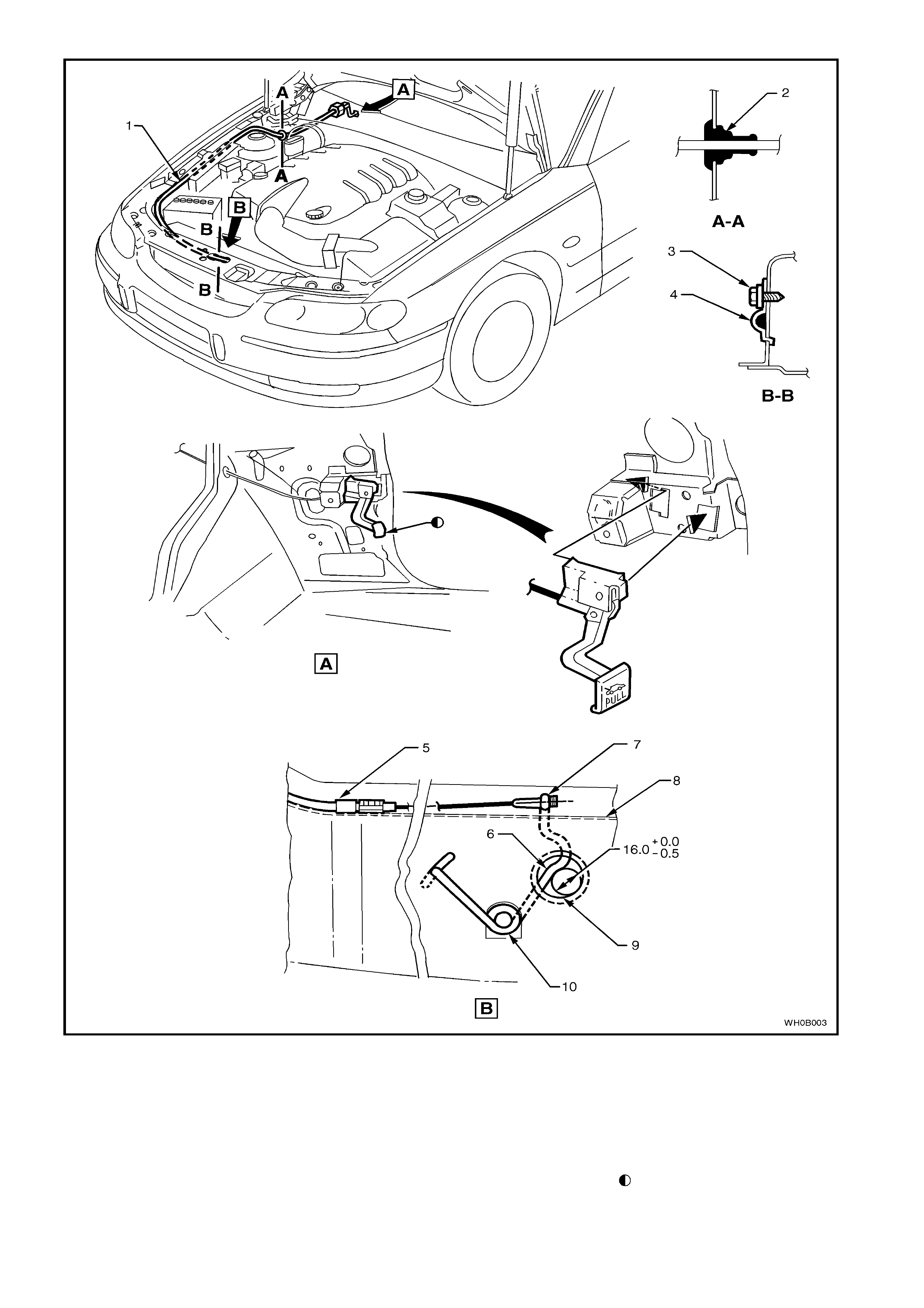
Figure 1B-5
Legend
1. Hood release cable.
2. Grommet.
3. Screw.
4. Clip.
5. Ferrule to be positioned
before retaining clip as
shown.
6. Set clearance in hood lock
guide using 16.0mm diameter
rod as shown.
7. No clearance permissible
between hood release spring
& nipple on assembly.
8. Apply HN 1225 to slot in guide
bush assembly.
9. Apply HN 1225 to inside of
plunger guide to a depth level
with release spring slot.
10. Apply HN1225 to coils of
release spring.
Release effort not to exceed
40N at hood release handle
lower edge.
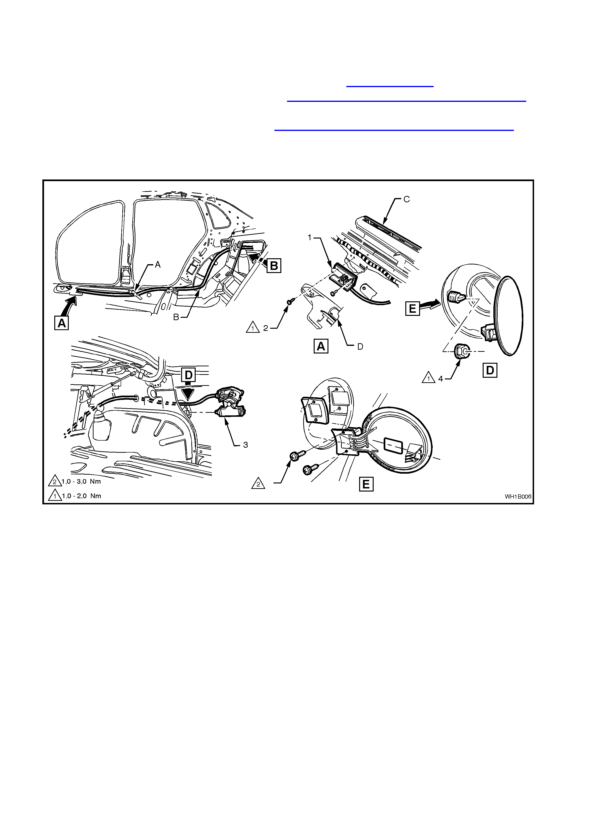
2.7 FUEL FILLER DOOR REMOTE RELEASE ASSEMBLY
REMOVE
1. Remove the right-hand side inner rocker panel cover (D), refer to Section 1A1 BODY.
2. Remove front seat outer lower front cover (E) refer Section 1A7 SEATS AND SEAT BELT ASSEMBLIES.
3. Remove the screws (2) attaching the lever assembly (1) to the rocker panel.
4. Remove the rear seat cushion and back, refer to Section 1A7 SEATS AND SEAT BELT ASSEMBLIES.
5. Remove the carpet from the rear compartment quarter panel.
6. Remove the nut (4) securing the fuel filler door release mechanism (3).
7. Release the cable from the mechanism and remove the cable and mechanism.
Figure 1B-6
Legend
A. Lay cable in swage and tape down
B. Bend over tab to retain cable C. Inner rocker panel cover
D. Front seat outer lower front cover
REINSTALL
Reverse removal operations.

3. TORQUE WRENCH SPECIFI CATIONS
Nm
Front Fender Liner Attaching Screws ................................... 1 - 3
Fender Securing Screws....................................................... 3 - 8
Engine Hood Gas Support Strut Securing Screws ............... 10 - 14
Engine Hood Gas Support Securing Ball Stud ..................... 6 - 14
Engine Hood Hinge Supporting Screws................................ 10 - 25
Engine Hood Cable Assembly Clip Securing Screw............. 1 - 3