
SECTION 1D - BUMPER BARS
IMPORTANT
Before performing any Service Operation or other procedure described in this Section, refer to
Section 00 CAUTIONS AND NOTES for correct workshop practices with regard to safety and/or
property damage.
1. GENERAL I NFORMATI ON
Front and rear bumper bar assem blies f itted to W H Series models ar e of polypropylene m aterial. The centr e of the
front bum per bar facia is attac hed to a steel bumper support beam which, in turn, is attached to longitudinal fram e
mem bers and to the front fender sheet metal on each side. The rear bum per bar facia is attached to the body at
the sides and at the rear. A steel bumper support beam is attached to the rear longitudinally.

2. SERVICE OPERATIONS
2.1 PAINT SYSTEM
The paint system for the bumper bar facias is relatively straightforward as long as the correct materials are used.
Normal refinish lacquers will not adhere to polypropylene/EPDM bumpers.
CAUTION: Thorough cleaning and the use of Holden’s approved paint and additives is required. Other
material s and methods may dama ge the plastic or lead to premature paint failure.
The following service recommendations are compiled to guide Dealerships on the correct materials and methods to
be employed when refinishing bumper bars and also preparing new parts for service installation.
RECOMMENDED MATERIALS
Front and rear bumper bars installed on WH Series Models are made from high impact strength
Polypropylene/EDPM plastic.
It is essential that only Holden’s approved methods, materials, paints etc; be employed when paint repair operations
are performed and when preparing new parts for installation to the vehicles.
The Holden’s approved materials are:
-PPG* Bodykleen 920-30509
-PPG* Plastpak Universal Anti Static Cleaner 920-39237
-PPG* Hyperprime Primer 499-48559
-PPG* Plastpak Flexible Additive for Two Component Products 499-35484
-PPG* Cobra Basecoat - Colour 534 Line
-PPG* Basecoat Thinner 920-34926
-PPG* 2K Clearcoat 455-30900
-PPG* 2K Acry lic Enamel Solid Colour 426 Line
-PPG* 2K MS Hardener Normal 980-35239
-PPG* 2K Reducer Fast 920-19148
* PPG is a trademark of PPG Australia.
COLOUR FINISHING OF REPLACEMENT PARTS
Spare parts require priming and coating with approved topcoat colour before installation to the vehicle.
1. Order part and paint materials.
2. Read SAFE HANDLING OF ALL PAINTS CONTAINING PPG 2K MS HARDNER further in this Section and
obtain the required respirator.
3. Cleaning. W ash unpainted polypropylene bum per bar all over with a made-up s olution of 9 parts fr esh water: 1
part PPG Bodykleen 920-30509. Apply with a clean non-metallic pad (recommended Scotchbrite 448) to scuff
the surface.
4. Rinse with fresh cold water.
5. Using a clean cloth s aturated with PPG Plastpak Universal Anti- static cleaner 920-39237, wash the entire par t,
allowing contact for a minimum 15 seconds.
6. Dry thoroughly using a separate, clean, dry cloth.
7. Repeat steps 5 and 6 another three times. Each time using a separate clean dry cloth.
NOTE: If a static charge has built up on the bumper surface (after completing all cleaning operations) dampen the
surface with the Plastpak Universal Anti-static cleaner and allow to evaporate dry. This will impart full anti-static
properties to the bumper.
8. Prim ing: Apply one light double (approxim ately 3 - 8 µm D.F.B.) coat (unifor mly wet) of PPG Hyperprime pr imer
499-48559 to all the bumper surface intended for topcoat. Recommended air pressure range of 320 - 420 kPa.
9. Allow to air dry 15-20 minutes @ 20° C. DO NOT SAND.

PAINT
Solid Colour
To the matched colour, add Flexible Additive then Hardener and Reducer in the following ratios:
-426 line colour - five parts by volume
-Flexible Additive 499-35484 - one part by volume
-2K MS Hardener 980-35239 - three parts by volume
-2K Reducer 920-19148 - 10-20% by volume
Stir thoroughly and strain. Put on the air supplied respirator. Using a 1.4 - 1.8 mm fluid nozzle on a standard spray
gun, apply one medium wet coat. Apply a further one or two coats to achieve coverage allowing a 3 - 5 minutes
flash-off time between coats. If low baking, this can be done immediately (no more than five minutes flash-off) at
60°C for 40 minutes. If air drying, allow 16 hours to dry (correct film thickness is 40 - 50 microns).
Cobra Basecoat, Metallic, Pearl or Solid Colour
Thin the matched basecoat colour with Cobra Basebuilder, 920 line at a 1:1 mix ratio and stir thoroughly, strain
material, and using a 1.4 - 1.6 mm gravity feed spray gun, apply one medium wet even coat. Allow to flash off for
5 minutes before applying the next coat.
Apply one or two further coats to achieve a uniform and even coverage with five minutes flash-off between coats.
Allow 10 - 20 minutes drying before applying clearcoat.
Mix 2K Clearcoat with Flexible Additive then Hardener and Reducer in the following ratios:
-2K Clearcoat 455-30900 - five parts by volume
-Flexible Additive 499-35484 - one part by volume
-2K MS Hardener 980-35239 - three parts by volume
-2K Reducer 920-19148 - 20% by volume
Stir thoroughly and strain. Put on the air supplied respirator. Using a 1.4 - 1.8 mm fluid nozzle spray gun set-up,
apply one medium wet coat to the basecoat (after allowing the Basecoat 10 - 20 minutes drying time). Apply a
further one or two wet coats after a 3 - 5 minutes flash-off between coats. If low baking, this can be done
immediately after the last coat but do not allow more than five minutes flash-off. Bake at 60°C for 40 minutes or, if
air drying, allow 16 hours.
REPAIRING COLOUR COAT
Superficial damage to the paint film and/or plastic surfaces may be rectified by sanding and repainting. Parts having
deep gouges in the plastic surface should be replaced because repair methods using filling materials and thinning
down of the plastic section may reduce overall impact strength.
For shallow paint damage, follow the procedure listed under “Colour Finishing Of Replacement Parts”, using P800
paper to sand down imperfections and using, eg. Scotchbrite** 448 pad or P1200 paper, scuff and key existing
paintwork.
Basecoat and Clearcoat can be spot repaired by blending away the basecoat colour but spraying the complete
bumper with Clearcoat. Solid colours are best sprayed as complete panels. If the damage extends to the plastic
surface, this must be primed with Plastpak Universal primer after the correct cleaning procedure.
** Scotchbrite is a trademark of 3M Co.
CAUTION: Drying of all products may be accelerated by heat, but to avoid distortion, unsupported bumpers
should not be heated in an oven or by lamp above 60°
°°
°C.
SAFE HANDLING OF ALL PAINTS CONTAINING PPG 2K MS HARDENER
PPG 2K MS Hardener contains not more than 0.3% free isocyanate monomer.
FOR AUTOMOTIVE AND INDUSTRIAL USE ONLY. This product requires professional equipment and experience
for safe handling. Not for use by the general public.
Read and understand the instructions and warnings contained in data sheets and on the label of the can containing
the base product before opening the can. Follow all directions and warnings carefully, otherwise DO NOT use this
product.
Warnings and precautions on the label also apply to the mixture of hardener and base.
Breathing of vapour, spray mist and dust from sanding is harmful and may cause lung irritation and allergic
respiratory reaction. Irritates skin and eyes.
When mixed with the appropriate base, apply in a spray booth fitted with an effective exhaust system. Comply with
local legislation applicable to spray painting of motor vehicles. Wear a positive pressure air supplied full face
respirator (complying with Australian Standard 1716 - 1984) and gloves while spraying and during all subsequent
use. The spray booth area should be isolated from other people while spraying is in progress and until all spray mist
has been effectively dispersed.

FIRST AID
If affected by inhalation of vapour or spray mist, remove to fresh air. If breathing difficulty persists or occurs later,
consult a doctor and have label information available. In case of eye contact, flush immediately with plenty of water
for 15 minutes; call a doctor. In case of skin contact, remove contaminated clothing and wash skin thoroughly with
soap and water. Immerse contaminated clothing in water for 24 hours and do not re-use until it has been laundered.
In case of spillage, absorb onto dry sand or earth, remove from the work area, cover with water for 24 hours before
disposal. Treat empty hardener cans in the same manner.
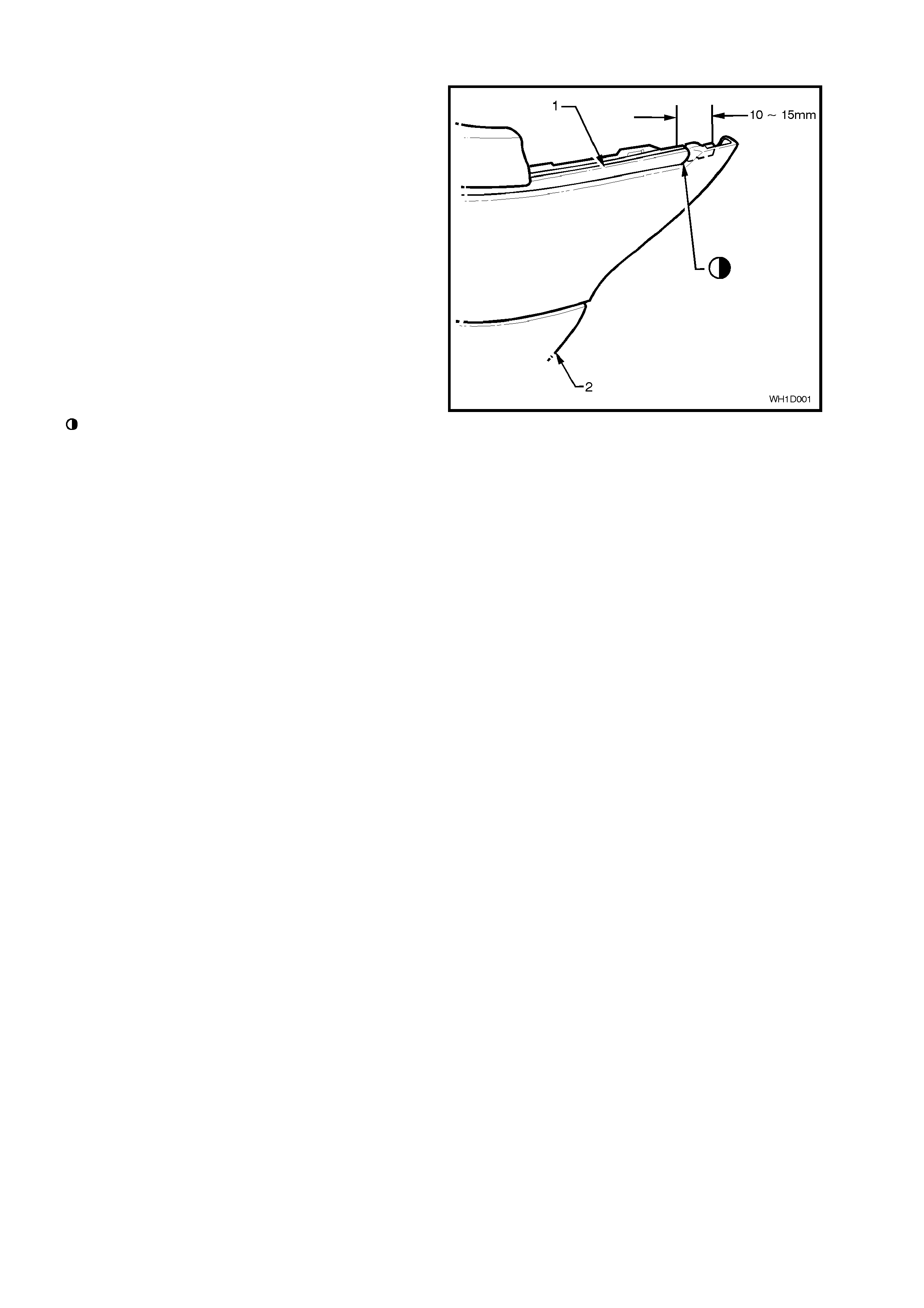
2.2 BUMPE R RUB S T RIP MOULDING
REMOVE
1. Carefully remove the rub strip moulding (1)
from the bumper bar (2), taking care not to
damage the bumper paint finish.
CAUTION: Ensure all remains of insert and
adhesive are removed before proceeding.
REINSTALL
1. Warm rub strip moulding (1) until flexible and
adhesive becomes tacky.
2. While still warm and flexible, place the
moulding into the ends of the bumper bar
recess and smooth down into place, working
across the bumper bar face.
NOTE: Use a clean shop rag to exert pressure
while applying moulding.
Prior to installation, tr im m oulding to length and
seal both ends of the moulding with Bostik
Hardbond or equivalent Holden specification
HN 1244.
NOTE: Failure to seal ends of moulding will result
in discolouration.
Figure 1D-1
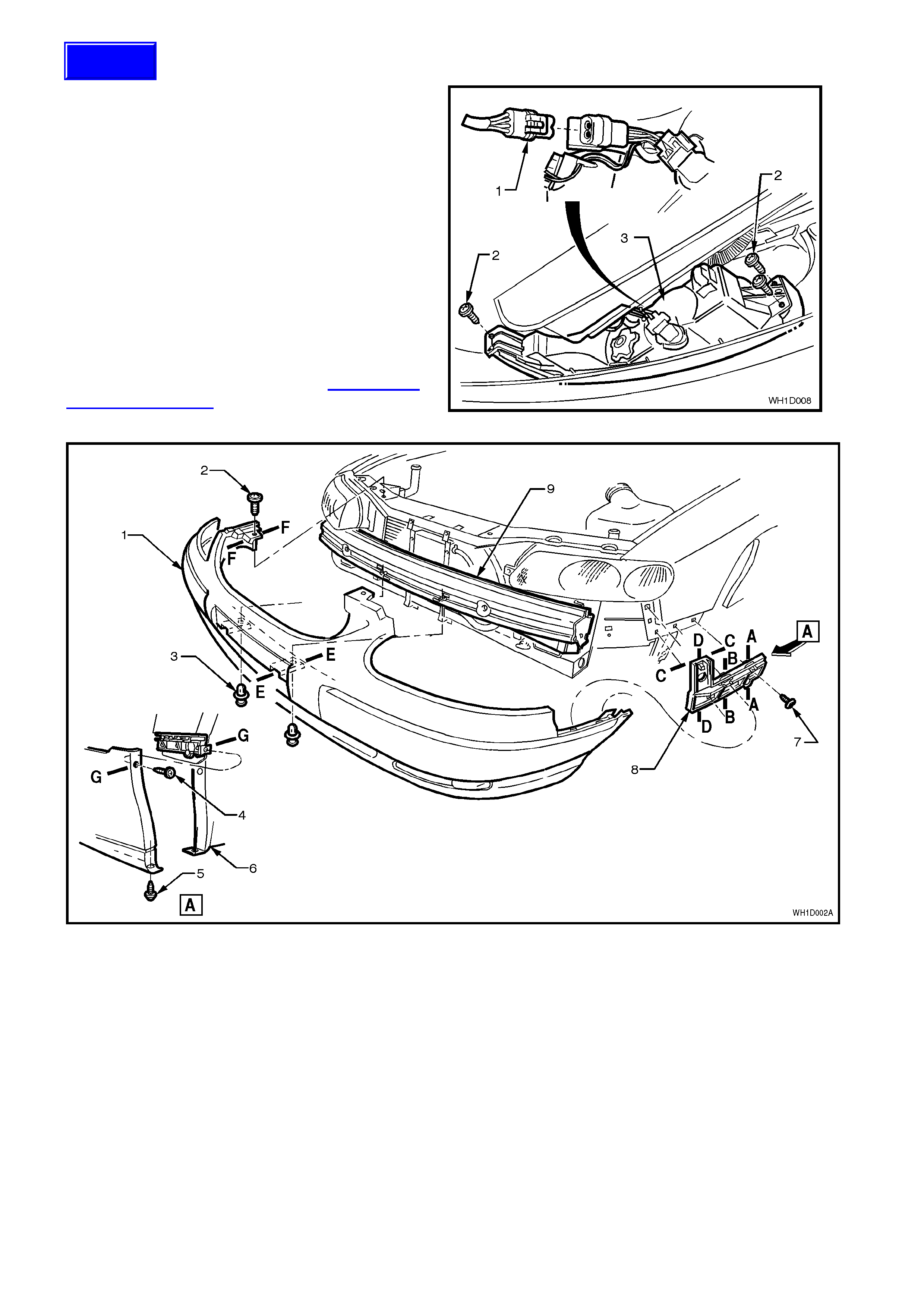
2.3 FRONT BUMPER BAR ASSEMBLY
REMOVE
1. Disconnect the fog lamp wiring harness
connector (1).
2. Remove the two scrivets (3) from behind
number plate, refer Fig. 1D-3.
3. Remove screws securing facia sides to front
fender wheel arch opening (4 and 5) and
radiator support upper panel (2), refer Fig. 1D-
3.
4. With the facia supported, pull the facia side
members out, disconnect the facia from the
guide rails (8), then slide the facia forward
removing the facia assembly, refer Fig. 1D-3.
NOTE: The support beam (9) should not be
removed unless damaged, refer to Section 1A2
BODY DIMENSIONS for alignment details.
Figure 1D-2
Figure 1D-3
Legend
NOTE: For Sections A-A thru G-G refer Fig. 1D-5.
1. Front Bumper Facia.
2. Screw (2 places).
3. Scrivet (2 places).
4. Screw (2 places).
5. Screw (2 places).
6. Front fender inner liner.
7. Screw (6 places).
8. Front bumper guide rail.
9. Front bumper support beam.
Techline
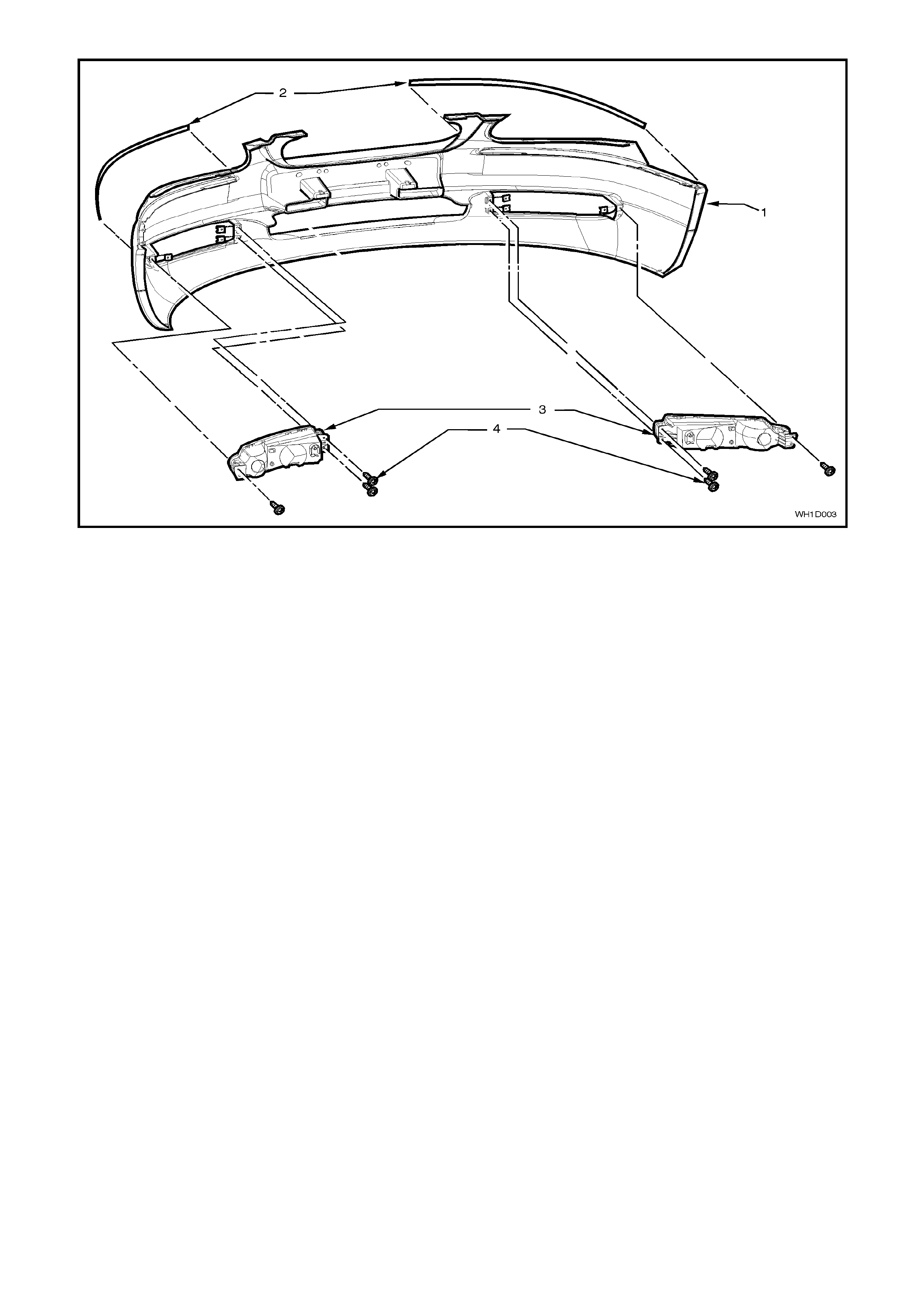
Figure 1D-4
Legend
1. Front Bumper Facia.
2. Bumper Rub Strip Moulding. 3. Fog lamp assembly.
4. Screw (3 places).
DISASSEMBLE
1. Place the front bumper bar facia assembly face
down on a clean protected surface.
2. Remove screws securing fog lamps (2) and
withdraw fog lamp (3) from front bumper facia,
refer Fig. 1D-2.
REASSEMBLE
Reverse disassembly operations.
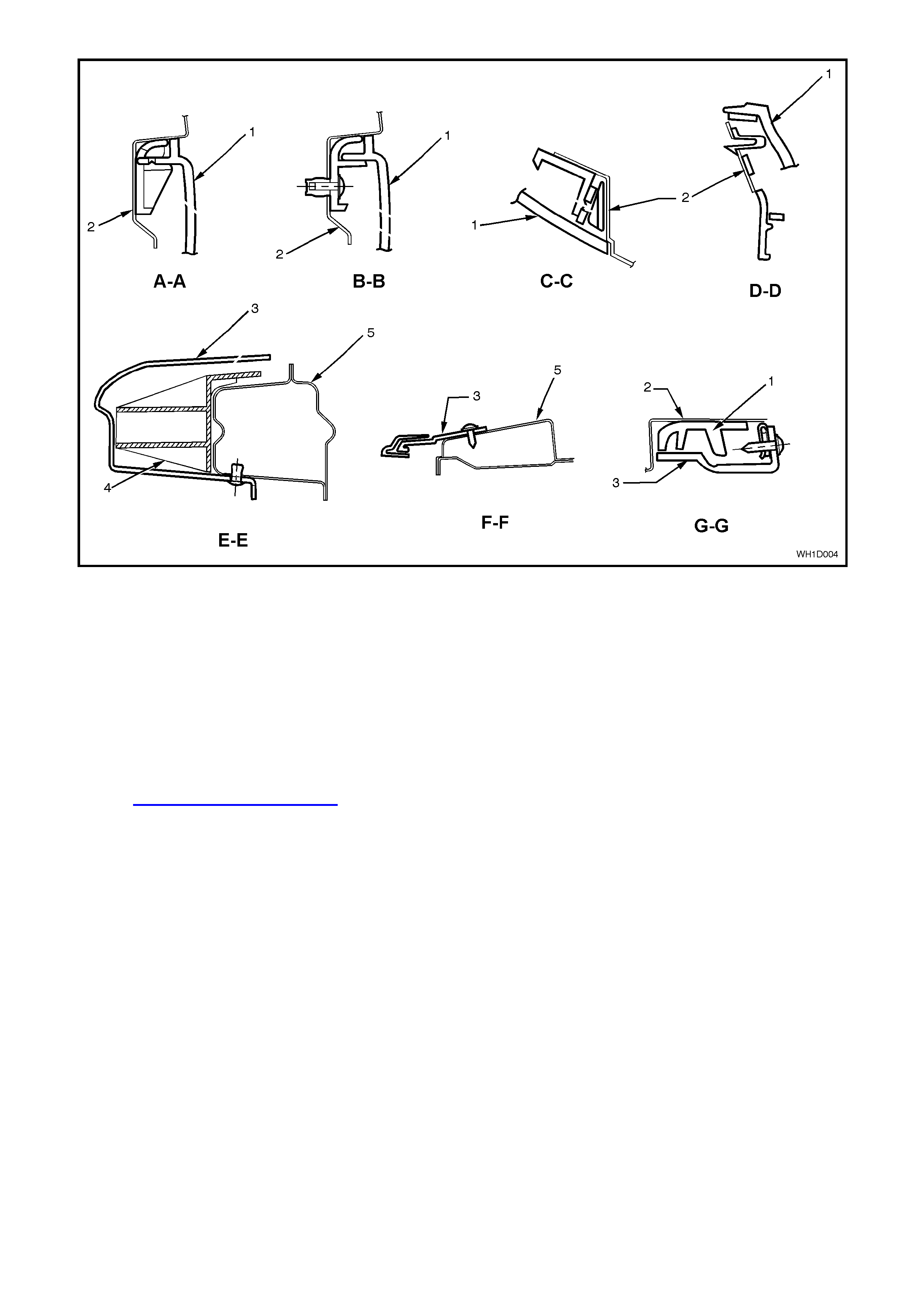
Figure 1D-5
Legend
1. Front bumper guide rail.
2. Front fender. 3. Front bumper facia.
4. Front bumper support beam. 5. Radiator support panel.
REINSTALL
Reverse removal operations. Snap the facia onto
retainers at guide rails, one side at a time, (r efer to
section C–C, Fig. 1D-5) then adjust the facia to
ensure correct fender, hood/headlamp clearance.
Refer to Section 1B SHEET METAL for engine
hood clearance specifications.
Tighten all fasteners to the correct torque
specification as specified at the end of this Section.
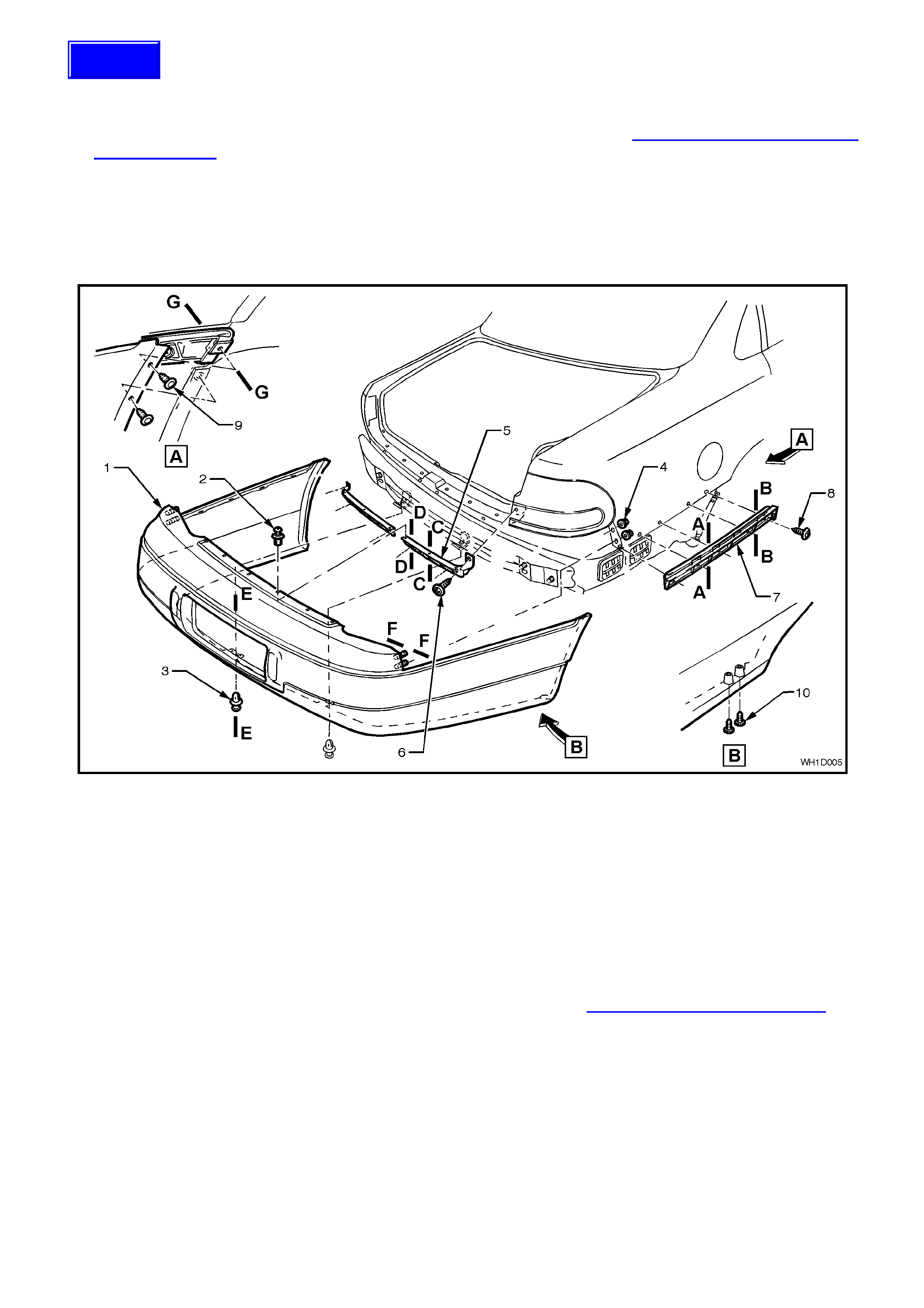
2.4 REAR BUMPER BAR ASSEMBLY
REMOVE
1. From within the rear com par tm ent rem ove the rear quar ter trim panel, r efer to Sect ion 1A8 HEADLINING AND
REAR END TRIM.
2. Remove the four nuts (4) securing the rear bumper assembly to the rear quarter panel (below tail lamps).
3. Remove the two screws (9) securing the rear bumper facia at each upper wheelarch opening and two screws
(10) at the lower wheelarch opening. Remove six fast eners (2) at the upper edge of facia and two fas teners (3)
at lower edge of facia.
4. W ith the facia supported, pull the facia s ide mem bers out to disc onnect it from the f acia side supports ( 7), then
slide the facia rearwards, removing the facia.
Figure 1D-6
Legend
NOTE: For Sections A-A thru G-G refer Fig. 1D-8.
1. Rear bumper facia.
2. Bumper facia upper fastner (4
places).
3. Bumper facia lower fastner (2
places).
4. Bumper facia attaching nuts
(4 places).
5. Bumper facia support bracket.
6. Bumper facia support bracket
screw (5 places).
7. Bumper facia side support.
8. Bumper facia side support
attaching screw (5 places).
9. Bumper facia upper wheel
arch attaching screw (4
places).
10. Bumper facia lower wheel
arch attaching screw (4
places).
NOTE: The support beam should not be removed unless damaged, refer to Section 1A2 BODY DIMENSIONS for
alignment details.
REINSTALL
Reverse removal operations. Locate studs (two each side) on the facia to holes in the rear quarter panel. Snap the
facia onto retainers at the side support, adjust the facia to ensure correct clearance.
Tighten all fasteners to the correct torque specification as specified at the end of this Section.
Techline
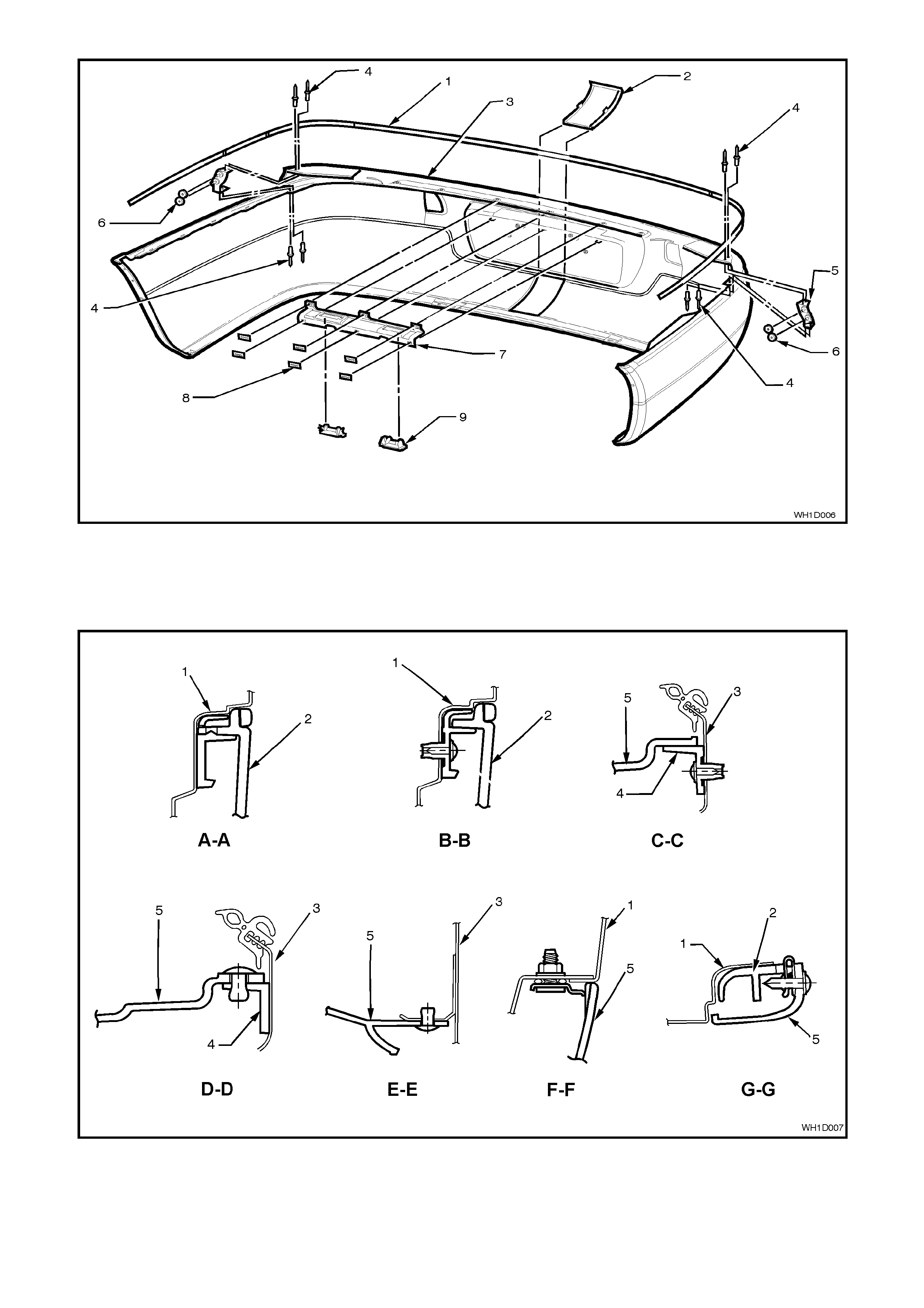
Figure 1D-7
Legend
1. Bumper rub strip moulding.
2. Tow bar opening cover.
3. Rear bumper facia.
4. Rivets.
5. Mounting bracket.
6. Seals.
7. Carrier licence plate lamp.
8. Clips.
9. Licence plate lamps.
Figure 1D-8
Legend
1. Rear quarter panel.
2. Bumper facia side support. 3. Lower back panel assembly.
4. Bumper facia support bracket. 5. Bumper facia.

3. TORQUE WRENCH SPECIFI CATIONS
Nm
Front bumper facia wheelarch securing screws ................... 1.0 - 3.0
Front bumper facia top securing screws............................... 2.5 - 4.0
Fog lamp attaching screws................................................... 1.0 - 3.0
Rear bumper bar assembly attaching nuts........................... 6.0 - 9.0
Rear bumper bar facia securing screws............................... 1.0 - 3.0
Rear bumper facia wheelarch securing screws.................... 1.0 - 3.0