
SECTION 1F - SUNROOF
IMPORTANT
Before performing any Service Operation or other procedure described in this Section, refer to Section
00 CAUTIONS AND NOTES for correct workshop practices with regard to safety and/or property damage.
1. GENERAL I NFORMATI O N
The sunroof is a tinted glass panel, electrically operated, two-way sliding and tilting type, equipped with an internal
sliding sunshade and front edge wind deflector. The sunroof is operated by a rocker type switch (which is backlit)
centrally located in the vehicle's headlining in front of the sunroof vent aperture. A Sunroof Control Unit (SCU)
provides several pre-programmed functions and the facility to program an additional option.
PRE-PROGRAMMED FUNCTIONS
Soft touch
By a single touch of the switch the roof can be fully opened to the maximum tilt position or the maximum slide
position.
Variable tilt position
The panel can be closed from tilt in four steps by continuously pressing the switch and releasing in the desired
position.
Jamming protection (Safety Feature)
When closing the sunroof by soft touch or by autoclose, the sunroof automatically opens when it encounters an
obstacle. The roof will continue to try to close until the obstacle is removed.
Auto-close function
Three seconds after switching off the ignition the sunroof will close automatically. This can be prevented by pressing
the switch once within three seconds after the ignition is switched off.
One-way closing
This feature always closes the glass panel from above, assuring a flush fit of the panel.
OPTIONAL PROGRAMMABLE FUNCTION
Comfort position in the sliding range
With this featur e you will be able to progr am a preset s topping position of the glass panel in the sliding range of the
sunroof. The glass panel will stop at the preset position when opened via the soft touch operation.

1.1 GENERAL DESCRIPTION
Glass panel movement into the venting and sliding positions is controlled by:
Continuous Control (pressing the switch longer than 0.3 second):
• Full control over the glass panel movement in slide position.
• Releasing the switch will stop the glass panel movement.
• A full stop in maximum slide and closed position.
Four Steps Down Tilt Adjustment (pressing the switch longer than 0.3 second):
• W hen closing the sunroof from minimum tilt position by pressing the switch c ontinuously, the glas s panel
will stop briefly in four intermediate positions.
• Releasing the switch will stop the glass panel movement.
• To continue the stepped operation, press the switch again.
One Touch Control (pressing and releasing the switch within 0.3 second):
• Automatic glass panel movement towards full open or full closed position (slide and tilt).
• Anti-jamming protection while closing.
• The glass panel movement can be interrupted by pressing the switch.
Auto-close
When the ignition is switched off, the glass panel will close after a three-second delay:
• Anti-jamming protection while closing.
• Pressing the switch within three seconds after the ignition switch off will cancel Auto-close.
• Auto-close will not be activated if any other function is active.
One Way Closing
To ensure perfect positioning of the glass panel after closing, the glass panel will always close from above
(even when closed from a slide position).
Interior Trim
Sunshade
Sunshade operation depends on glass panel movement as follows:
• Moving the glass panel to tilt position, the sunshade automatically opens to a vent position and can be
moved to full open position by hand.
• Moving the glass panel into slide position, the sunshade will move together and can also be further
opened by hand.
• Closing the sunshade always has to be done manually. The sunshade can only be closed completely
when the glass panel is in closed position.
Wind Deflector
The wind defector automatically comes up when the glass panel moves into sliding positions and goes down
when the glass panel closes again.
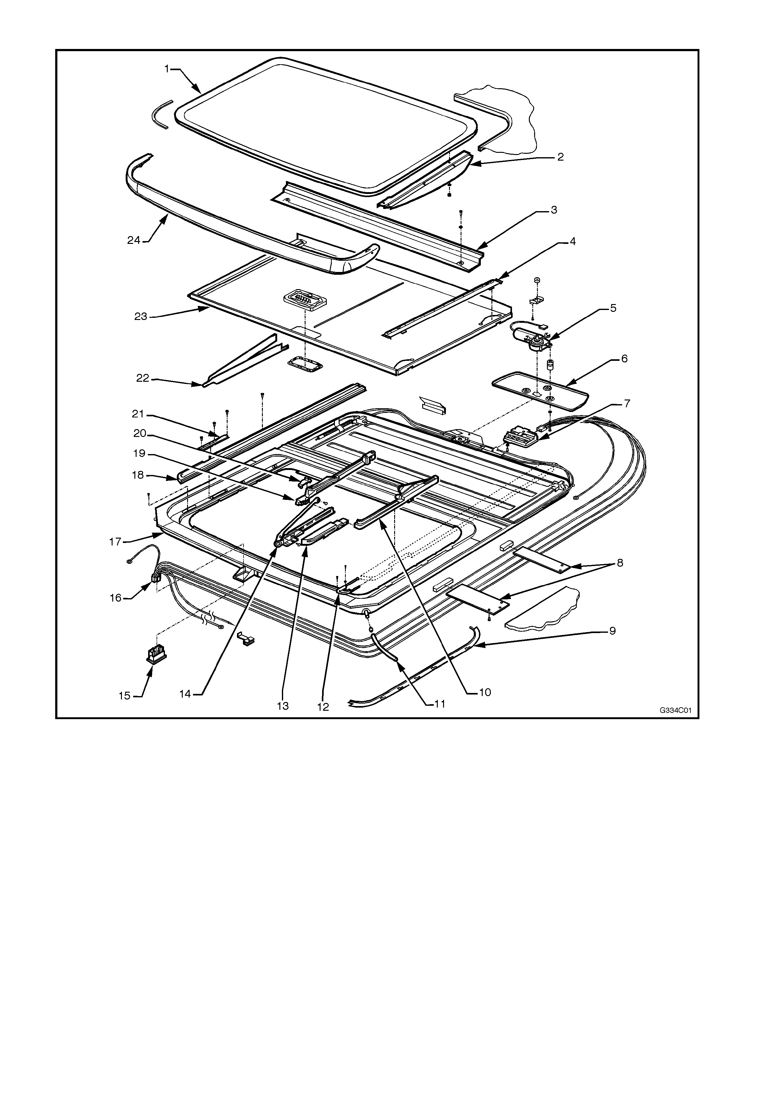
Figure 1F-1
1 Glass Panel (includes Curve-
on Panel – not shown) 10 Rear Driving Slide 19 Guide Rail Mechanism (Track)
2 Exterior Cover 11 Drain Tube 20 Rear Basic Slide
3 Drain Channel 12 Retraction Mechanism 21 Blocking Catch
4 Sunshade Guide 13 Front Driving Slide 22 Locator
5 Drive Motor 14 Fuse and Fuse Holder 23 Mechanism Cover
6 Drive Motor Cover 15 Front Basic Slide 24 Sunshade
7 Sunroof Control Unit (SCU) 16 Switch 25 Wind Deflector
8 Side Support Bracket 17 Harness
9 Side Trimming 18 Frame

2. SERVICE OPERATIONS
The following service operations for the sunroof are those that can be performed by the general service technician.
The procedure for the removal and installation of the sunroof assembly has deliberately been omitted due to the
skills and special tools required, which would be beyond the scope of the general repair technician.
Also, as the sunroof assembly is chemically bonded to the vehicle’s roof panel, damage to the sunroof and roof
panel will result if removal is performed, necessitating sunroof replacement and roof panel repair.
If assistance is required in the servicing or installation of the sunroof assembly, contact the authorised Hollandia
sunroof specialist in your area or contact Hollandia Sunroofs Australasia on (02) 9540 4811.
2.1 DRIVE MOTOR
REPLACE
1. Remove or drop rear of headlining to access
drive motor cover.
2. Rem ove the bolts securing the dr ive motor and
cover, drive motor now drops down.
3. Disconnect the drive motor connector from the
sunroof control unit.
4. Connect new drive motor wiring harness
connector to sunroof control unit.
5. Check drive motor for proper operation in both
directions, refer to 3.3 T EST ING EL ECTRICAL
COMPONENTS in this Section.
6. Install drive motor, spacers, cover and
attaching bolts.
7. Check the sunroof for correct operation.
8. Install the headlining.
2.2 SUNROOF CONTROL UNIT (SCU)
REPLACE
1. Remove or drop rear of headlining to access
drive motor cover.
2. Utilising a manual crank, vent the glass panel
completely.
3. Remove the LH mechanism cover.
4. Utilising the manual crank, close the glass
panel 1.5 revolutions.
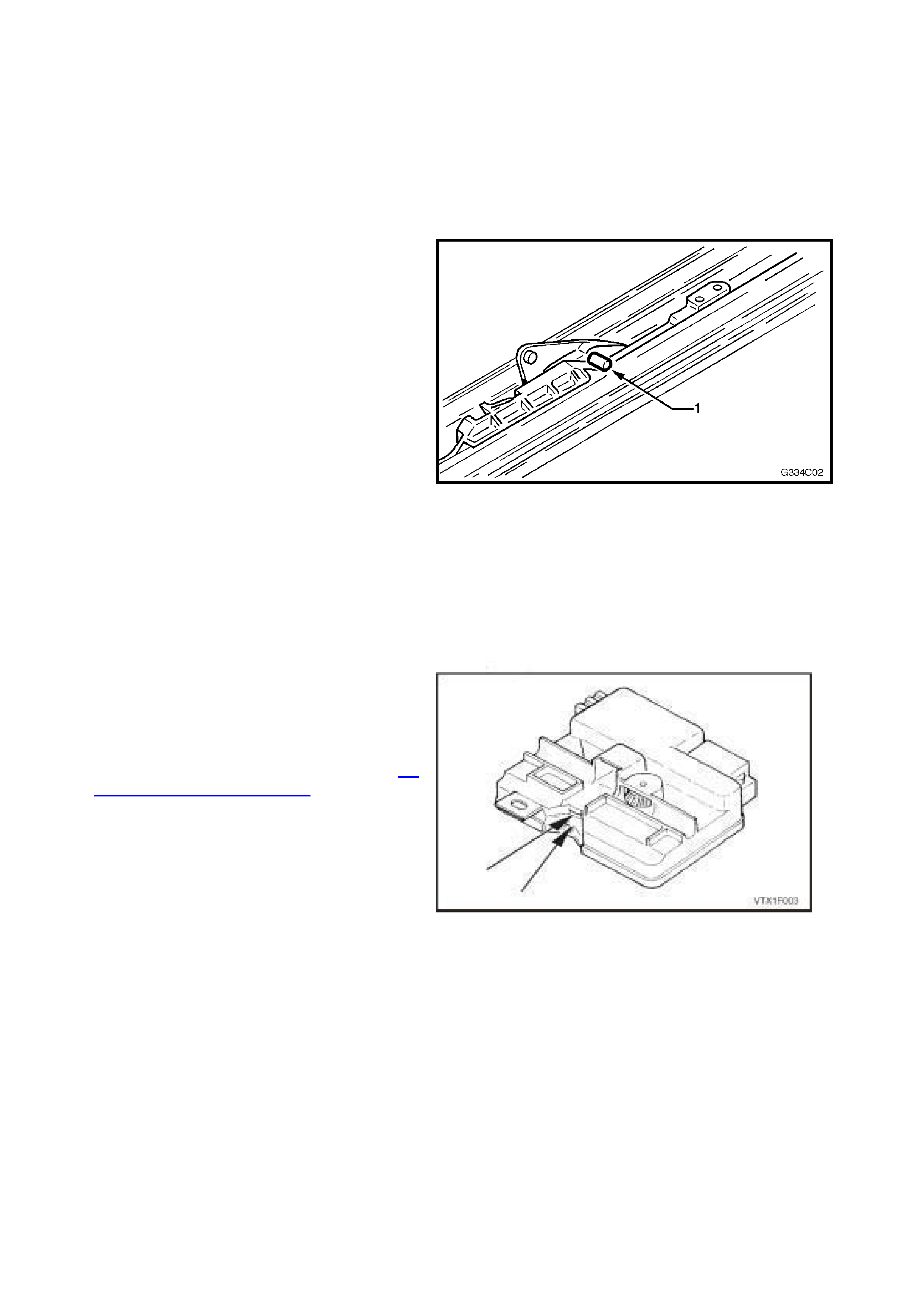
5. Place pin in each 2.5 mm bras s hole as shown.
Venting the glass panel, turn crank handle a
quarter of a turn forward. T he pin (1) stops the
mechanism at the desired location.
Figure 1F-2
6. Rem ove the bolts securing the dr ive motor and
cover, drive motor now drops down.
7. Disconnect the drive motor wiring harness
connector from the SCU and remove the drive
motor.
8. Disconnect the remaining wiring harness
connector from the SCU.
9. Rem ove the screw securing the SCU, lower the
front of the SCU to clear the cable. Slide the
SCU back and remove.
10. Inspect the new SCU for proper alignment of
spots on gearwheel in the viewfinder, refer to
Fig. 1F-3 and as described in 2.3
SYNCHRONISATION OF SCU in this Section.
Lowering the front of the SCU low enough for
cable clearance, slide forward, engage the lip
of cable plate in the SCU slot. Straighten SCU
horizontally and tighten screw.
NOTE: If the spots are not aligned, turn the top
mount cable gear until each spot appears aligned
over one another in the view finders (refer to
Fig. 1F-3).
11. Connect both wiring harness connectors to the
SCU and install drive motor and cover.
12. Check the sunroof for correct operation.
13. Install the headlining.
14. Install the LH mechanism cover.
Figure 1F-3

2. 3 SYNCHRONISATION OF SCU
1. Remove the SCU and drive motor, refer 2.2 SUNROOF CONTROL UNIT (SCU) in this Section.
2. Align the two spots in the viewfinders Turn the exposed black cable gear mounted in top centre of the
SCU. When each spot appears directly in line with the other, top to bottom, stop.
NOTE: If the spots are not aligned, turn the top m ount cable gear until each spot appears aligned over one
another in the view finders (refer to Fig. 1F-3).
3. Reinstall the SCU and drive motor, refer 2.2 SUNROOF CONTROL UNIT (SCU) in this Section.
2.4 DRIVE CABLES
REPLACE
1. Rem ove mechanism covers, glas s panel, drain
channel, wind deflector, sunshade and
adjustment bracket.
2. Place mechanism in closed position.
3. Remove drive motor and SCU, refer 2.2
SUNROOF CONTROL UNIT (SCU) in this
Section.
4. Remove the gearwheel housing by removing
the two screws.
5. Remove gearwheel by inserting a screwdriver
and pushing forward and the gearwheel drops
down (refer to Fig. 1F-4).
Figure 1F-4
6. Remove the locator being careful to rem ember
the positioning of screws and the blocking
catch.
7. Pull mechanism all the way forward.
8. Push the mechanis m into tilt position as in Step
6, taking care not to inadvertently dislodge the
mechanism. Keep the front of the mechanism
down.
9. Rem ove the f ront s c rew and slide the r etrac tion
mechanism forward. Do not take out.
10. Slide mechanism in tilt position further forward.
11. Lift out cable and pull forward out from the
guide rail track.
Figure 1F-5
12. Inspect for proper length of new cable.
Lubricate the cable using Applied Chemicals
Tefoil + PTFE, Part No. 8-830, and slide into
the rail. Ensure oval shaped copper head of
cable seats firmly and diagonally across guide
channel (refer to Fig. 1F-6).
13. To check that cable is positioned correctly,
grasp long lever in tilt position with one hand,
the pivoting adjustment bracket in the other
hand and slide backwards. It should slide into
place (if blocked, turn cable slightly to reseat
copper oval head properly).
14. Pivot arm of adjustment bracket back down
into place. Slide the curve-on panel back into
place over the cap on long lever and ins tall the
Torx screw.
15. While holding the adjustment bracket stable,
push the catch mechanism into the slide
position as in Step 6. If mechanism stops after
approximately 100 mm preventing a full
rearward positioning, you failed to hold the
adjustment bracket stable, repeat this step.
Figure 1F-6

16. Slide whole mechanism rearwards to allow
installation of locator.
17. Slide the retraction mechanism rearwards,
install the screw and locator.
18. Repeat Steps 7 to 17 to replace the other
cable.
19. Slide both LH and RH mec hanisms to the f ront
position.
20. Push LH and RH mechanisms to the closed
position. Insert a pin in each 2.5 mm br ass hole
(pointed object) . Slide mechanism forward until
the pin stops the mechanisms movement at the
desired location (refer to Fig. 1F-2).
21. Install the new gearwheel, ensuring that it is
centred in the hole in the drive motor bracket.
Note that the core or centre of the gear has
splines (teeth). The splines do not extend
completely to one side of the gears inner core.
This is the down (bottom) side for mounting
(refer to Fig. 1F-4, refer above).
22. Install the new gearwheel housing.
23. Reinstall the drive motor and SCU, refer 2.2
SUNROOF CONTROL UNIT (SCU) in this
Section.
24. Inspect the sunroof for proper electrical and
mechanical functioning.
25. Install the headlining.
26. Install adjustment bracket, sunshade, drain
channel, glass panel, wind deflector and
mechanism covers.
27. Check the sunroof for correct operation.

2.5 TIMING OF DRIVE CABLES
1. Fully tilt panel.
2. Remove LH and RH mechanism covers & panel.
3. Put mechanism in fully closed position.
4. Remove the drive motor and SCU, refer 2.2 SUNROOF CONTROL UNIT (SCU) in this Section.
5. Remove the gearwheel housing by removing the two screws.
6. Remove gearwheel by inserting a screwdriver, push forward and the gearwheel drops down refer to
Fig. 1F-4.
7. Push the LH and RH mechanisms to the closed position. Place a pin in each 2.5 mm brass hole. Slide
the mechanism forward until the pin stops the mechanism’s movement at the desired location, refer to
Fig. 1F-2.
8. Install the new gearwheel, ensuring that it is centred in the hole in the drive motor bracket.
NOTE: The core or centre of the gear has splines. The splines do not extend completely to one side of the
gear’s inner core. This is the down (bottom) side for mounting, refer Fig. 1F-4.
9. Install the gearwheel housing.
10. Reinstall the drive motor and SCU, refer 2.2 SUNROOF CONTROL UNIT (SCU) in this Section.
11. Inspect the sunroof for proper electrical and mechanical functioning.
12. Install the headlining.
13. Install the LH and RH mechanism covers.
14. Check the sunroof for correct operation.

2.6 SEAL
REPLACE
1. Remove the LH and RH mechanism covers, glass panel and exterior covers.
2. Remove seal from the glass panel.
3. Remove all foreign debris from around the glass frame.
4. Install new seal, beginning at the centre front of the glass frame retaining channel.
5. Utilising your thumbs, insert the seal with enough pressure to ensure that the seal is flush (tight to frame).
6. Trim the glass panel seal length. When cutting excess, leave approximately six mm extra then work it
into the retaining channel.
7. Install the glass panel, refer to 2.11 GLASS PANEL in this Section.
8. Install the LH and RH mechanism cover.
9. Check the sunroof for correct operation.
2.7 SEAL
ADJUST
The proper positioning of the panel should result in
the seal firm ly contacting either the EPDM trim ring
or flanged metal circumference of the sunroof
opening. If the panel fits properly but gaps remain
between seal and trim ring it can be corrected as
follows:
1. Adjust glass panel properly against the rear of
the trim pr ofile, refer to 2.11 GL ASS PANEL in
this Section.
2. With a grease pencil mark the boundaries of
insufficient contact on the panel (at the front).
3. Remove the glass panel, refer to 2.11 GLASS
PANEL in this Section.
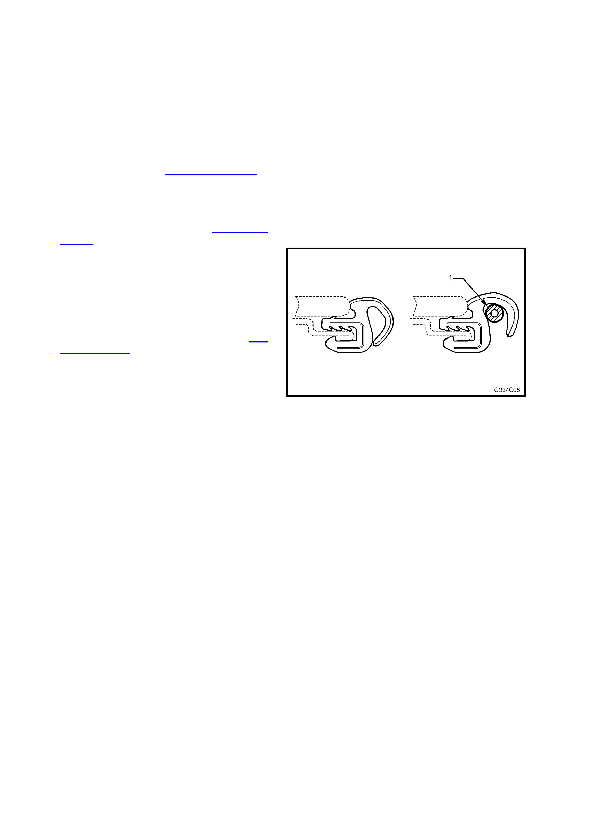
4. In the areas marked, insert a spacer (1) inside
the rubber seal. ( refer to Fig. 1F-7). Use a vinyl
tube with outer diameter of 3 mm for spacer
material.
5. Glue the spacer material to the seal with super
glue.
6. Install glass panel and adjust, refer to 2.11
GLASS PANEL in this Section.
Figure 1F-7

2.8 RETRACTION MECHANISM
REPLACE
1. Retract the glass panel completely.
2. Remove the wind deflector mounting nuts, and remove the wind deflector.
3. Remove the two screws and take the retraction mechanism forwards out of rail.
4. Install new retraction mechanism in rail.
5. Install the wind deflector.
6. Check the sunroof for correct operation.
2.9 GUIDE RAIL MECHANISM
REPLACE
1. Tilt mechanism completely.
2. Remove LH and RH mechanism covers, glass
panel, drain channel, wind deflector and
sunshade.
3. Fully retract mechanism.
4. Rem ove the locator, retraction mechanism and
rail screw.
5. Remove the wind deflector mounting nuts.
6. Slide rail sideways to unlock, then lift front up.
7. With rail front up, grasp retractor mechanism
and remove, then lower rail.
8. Fully close mechanism.
9. Lift and pull rail slowly forward over
mec hanism , as soon as the f ront of drive cable
appears at end of guide, lift out cable, now pull
mechanism carefully forward and lift out rail.
Inspect the new replacem ent rail & mec hanism
for cleanliness and completeness.
10. Slide the mechanism rearward out of rail for
cable installation access.
11. Install cable, then push m echanism forward on
rail (maintain access to rear rail area).
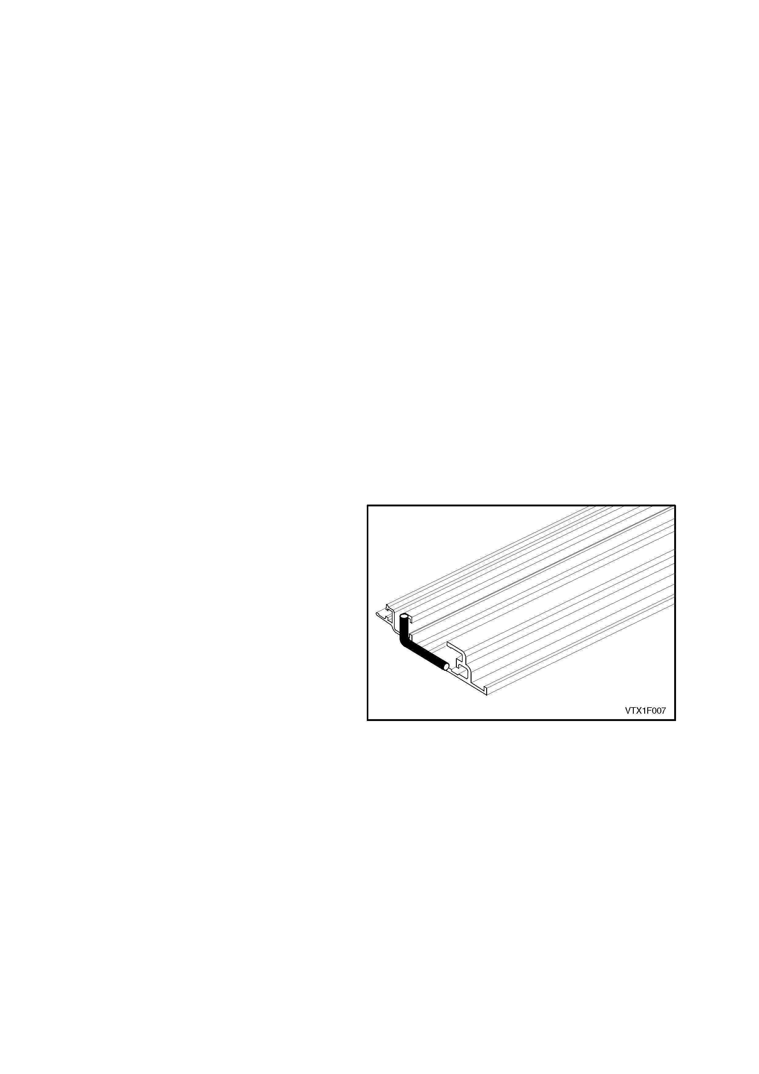
12. Apply a bend of liquid butyl as indicated on
Figure 1F-8.
13. Slide rail rearward over mechanism and drive
cable while holding the front of the mechanism
in place. As soon as the rail is fully extended
rearward, drop the front to frame and push rail
rearward into rail s top. Line up the screw holes
for proper positioning.
14. Retract mechanism totally.
15. Lift front of rail to reinstall retractor mechanism.
16. Drop rail down, push inboard until it locks in
place under the frame tabs.
17. Install all new rail screws starting at front for
proper positioning. Use original positioning of
screws by size.18. Replace wind deflector
mounting nuts loosely.
19. Tilt mechanism completely.
20. Inspect for proper mechanical functioning of
mechanism.
21. Install sunshade, drain channel, panel and wind
deflector.
22. Inspect functioning of sunroof, reinstall LH and
RH mechanism covers.
Figure 1F-8

2.10 BLOCKING CATCH
REPLACE
1. Remove the LH and RH mechanism covers and glass panel.
2. Fully retract mechanism.
3. Remove the locator.
4. Fully tilt the mechanism.
5. Remove the blocking catch by lifting out.
6. Clean out broken blocking catch debris if required.
7. Install new block ing c atch in mec hanis m, inser t the c irc ular eye stud into the m ec hanis m making s ur e the
second smaller stud falls cleanly into the mechanism slot.
8. Fully retract mechanism.
9. Install the locator.
10. Check for correct mechanical operation.
11. Install the glass panel and LH and RH mechanism covers.
2.11 GLASS PANEL
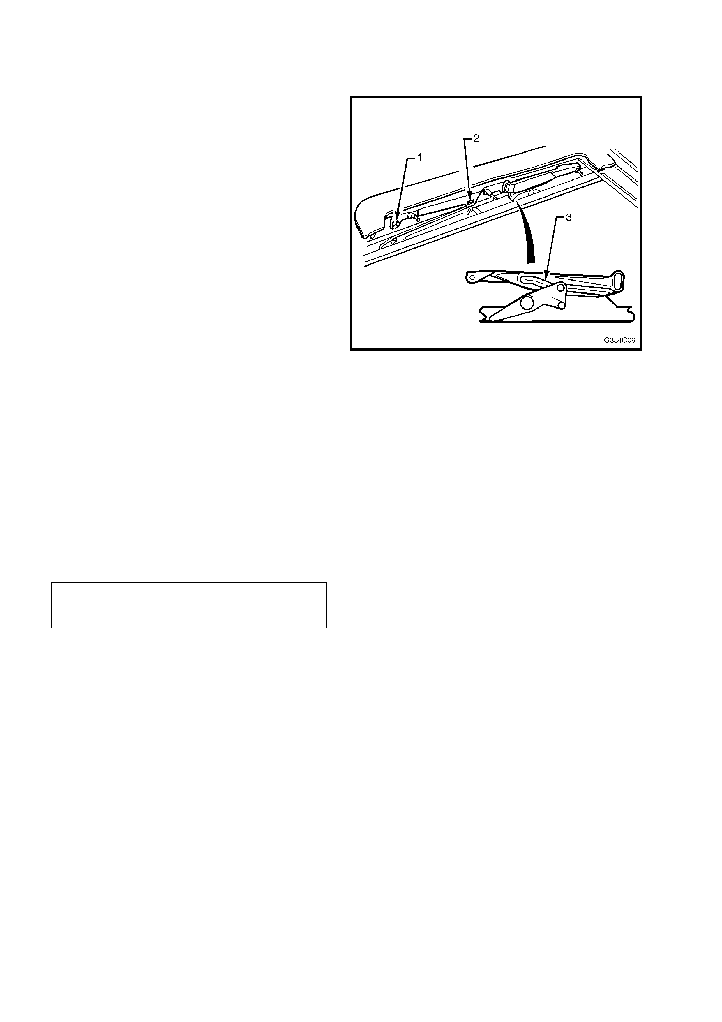
REMOVE
1. Place the glass panel in the tilt position.
2. Remove the two front screws (1) and the two
centre screws (2) and remove the glass panel.
REINSTALL AND ADJUST
1. Slide mechanism to the tilt position.
2. Inspect rubber seal and glass panel for
damage. Insert the glass panel.
3. Place the height adjustment curve (3), (which is
at the rear of the glass panel), over the
mechanism. Place vertical front lips on panel
between the right-hand and left-hand
mechanisms.
4. Lift the mechanism mounting bracket from the
inside and install two front and two centre
screws, leaving the four s cr ews loos e, ens uring
big washer is to front.
5. Put glass panel in closed position.
6. Adjust the glass panel to the front. Using a
business card, for example, check the tension
of the seal against the trim ring at the rear.
7. Tighten both centre screws (2).
8. Adjust height at the front and tighten front
screws (1).
9. Adjust height at the rear by loosening Torx
screws of the adjustment curve, adjust the
glass level with roof skin and tighten screws
(refer to Fig. 1F-9).
Figure 1F-9
GLASS PANEL HEIGHT
ADJUSTING SCREWS
TIGHTENING TORQUE 3.5 Nm
10. Check functioning of mechanism and
adjustments. Repeat Steps 6 to 9 to readjust
the glass panel if necessary.

3. DIAGNOSIS
3.1 FAULT DIAGNOSTIC CHARTS
The fault diagnostic charts included in this Section list possible causes and solutions and provide a reference to
a particular service operation to resolve the fault.
REPAIR ADVICE FOR MECHANICAL FAILURES
PROBLEM POSSIBLE CAUSE SOLUTION
While c yc l i ng the panel from tilt to cl ose it
begins sl i di ng rearward. Blocking catch is broken. Replace bloc king cat ch, refer t o 2.10
BLOCKING CATCH in this Section.
While c ycling full y open panel forward, it
begins ti l t i ng under roof ski n. Blocking catch is broken. Replace bloc king cat ch, refer t o 2.10
BLOCKING CATCH in this Section.
Panel is mis al i gned side to si de. Timi ng of dri ve c abl es incorrec t. Retim e dri ve c abl es, refer t o 2.5 TIMING OF
DRIVE CABLES in this Section.
Panel sl i di ng t oo slowly (with 13.5 V power
supply panel s houl d not take more than
7 seconds to cycle from f ul l retracti on t o
closure).
Weak bat tery.
Misaligned panel creating drag or fri ction.
Faulty drive m otor.
Dirty mechanism.
Charge or replace.
Retim e dri ve c abl es, refer t o 2.5 TIMING OF
DRIVE CABLES in this Section.
Test the dri ve motor as detailed in 3. 3
TESTING ELECTRICAL COMPONENTS in
this S e ction. If necessary, repl ace drive
motor, refer to 2.1 DRIVE MOTOR in this
Section.
Clean and grease mechanis m or replac e i f
necessary, refer to 2.9 GUIDE RAIL
MECHANISM in this Section.
Glass panel stopping prematurely. Sunroof control unit adj usted improperly.
Obstac l e i n mechanism or gui de track.
Synchronis e sunroof control unit, refer to
2.3 SYNCHRONI SATION OF SCU in this
Section.
Find object and remove.
Sunshade fai l s to open when glass panel i s
opened to tilt posit i on. Retraction mechani sm broken. Replace retraction mechanism, refer to
2.8 RETRACTI ON MECHA NI SM in this
Section.
REPAIR ADVICE FOR RATTLING NOISES
PROBLEM POSSIBLE CAUSE SOLUTION
Drain channel rat tles. Inspec t for ins ul at or tape between drain
channel and mechanis m.
Felt Pad
Add insul ator tape.
Add Felt Pad.
Rattles from side(s). Mounting bracket screws loose. Tighten cover pl at e screws.
Rattli ng i n dri ve motor area. Cover plate on drive motor has l oose
screws. Tighten c over pl at e screws.
REPAIR ADVICE FOR WIND NOISES
PROBLEM POSSIBLE CAUSE SOLUTION
Panel cl osed, excessi ve wind nois e. Glass panel seal not ti ght to trim ring.
Blocking catch broken.
Correct glass panel adjustment, ref er to
2.11 GLASS PANEL in this Section.
Replace bloc king cat ch, refer to
2.10 BLOCKING CATCH in thi s Section.
REPAIR ADVICE FOR WATER LEAKS
PROBLEM POSSIBLE CAUSE SOLUTION
Water c oming t hrough panel openi ng area. Blocked drain tubes.
Misaligned or k i nked drain tubes .
Housing frame dis t orted, seal to rail
disconnected.
Rear rail brack et has broken seal.
Inspec t drai n tubes cl ean openi ng, blow out
tubes.
Ensure t hat drai n tubes are co rrectly routed
through front and rear pillars .
Correct f rame curvature if nec essary reseal
rail to frame.
Reseal at rear rai l seal point, refer to
2.9 GUIDE RAIL MECHANISM in thi s
Section.
Headliner wet in front. Either f rame seam has i ncorrect seal. Reseal at seam.
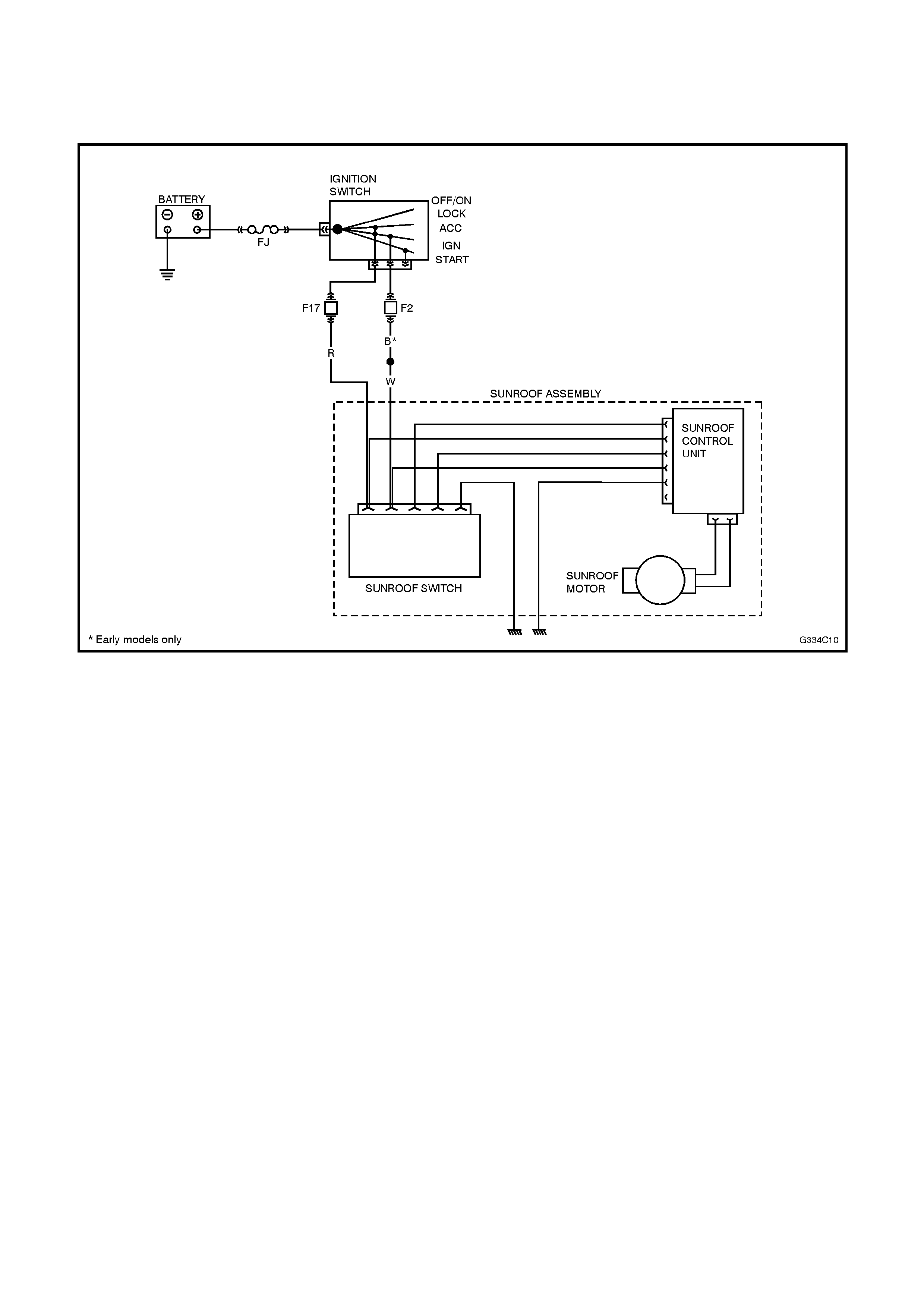
3.2 ELECTRICAL FAILURES
Use the following trouble shooting guide to locate
electrical failures or related problems. The circuit is
shown in Figure 1F-10.
Figure 1F-10
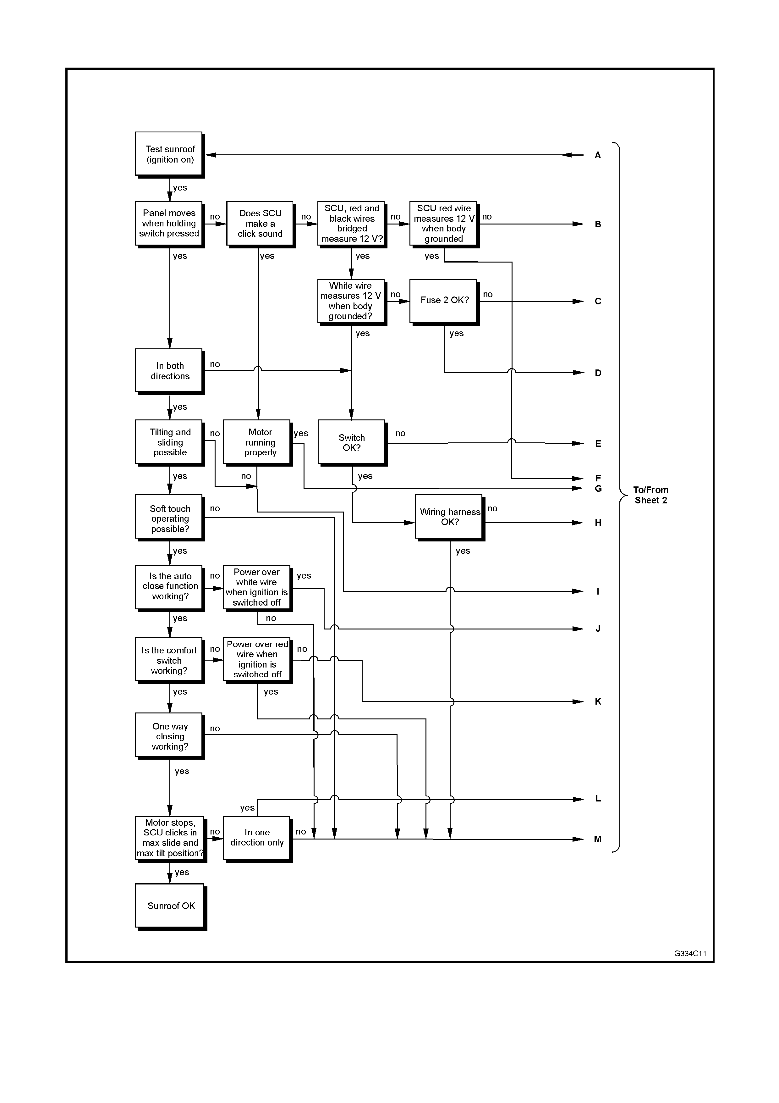
TROUBLE SHOOTING GUIDE (SHEET 1 OF 2)
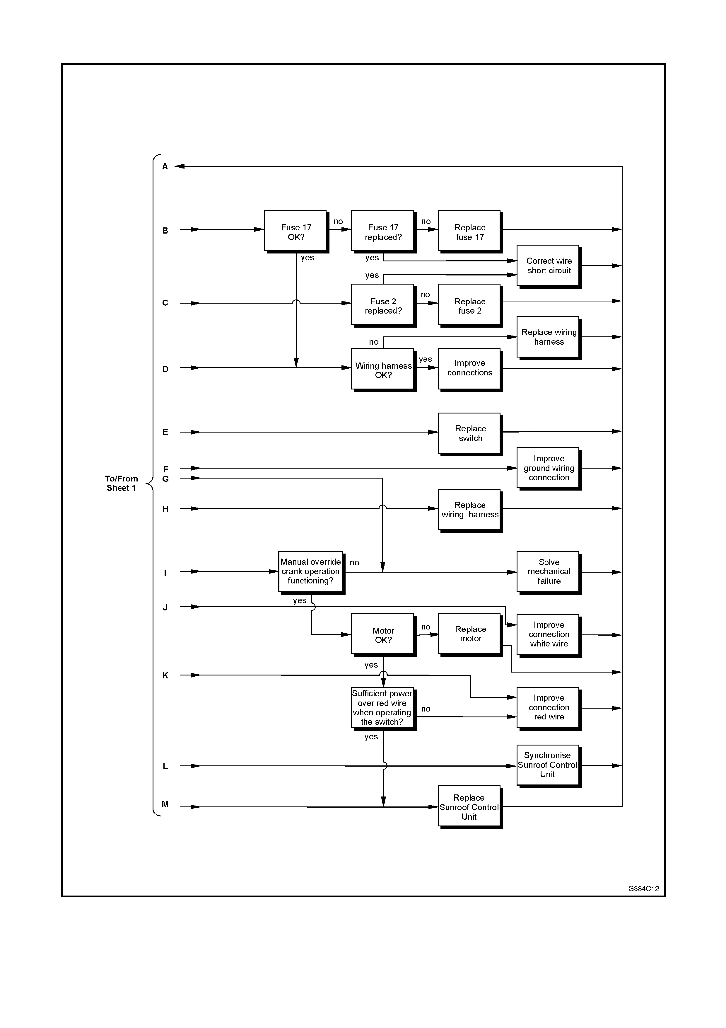
TROUBLE SHOOTING GUIDE (SHEET 2 OF 2)

3.3 TESTING ELECTRICAL COMPONENTS
Ensure that during testing electrical components, the sunroof is connected to a power source supplying 12 to 14 V.
If the Sunroof is installed, the battery needs to be attached and operable. During testing the ignition/accessory
switch should be on. This test can be accomplished with a test light or multimeter. Cable harness and drive motor
inspection requires the headlining to be removed.
FUSE
Visually inspect the fuse for damage.
WIRE HARNESS
Check if the power supply on the Red and Red/Black wires is OK. Inspect for broken/damaged wires. Inspect for
secure connection to the sunroof control unit. The wire harness connector is numbered to aid in proper installation:
SWITCH
Inspect for correct power supply to the sunroof operating switch, accomplished by using a test light on the connector
at the switch bracket. Operate the switch connector to assure movement in front and rear sliding positions.
DRIVE MOTOR
Disconnect the drive motor wire (Green/Black) from the sunroof control unit. Remove the drive motor. Using a
double wire of sufficient length, connect direct to battery. Check the drive motor for correct operation in both
directions. This is accomplished by reversing the connection of the double wire. The drive motor has an in-built
thermal cutout device that automatically switches the drive motor off during periods of overload. After a cooling
down period the drive motor will function properly.