
SECTION 0A - GENERAL INFORMATION
IMPORTANT
Before performing any Service Operation or other procedure described in this Section, refer to
Section 00 CAUTIONS AND NOTES for correct workshop practices with regard to safety and/or
property damage.
1.GENERAL I NFORMATI ON
The WH Series feature a new sixth window body design with changes to front and rear end sheet metal and
tail lamps. Included are an adjustable tilt/reach steering column, supplemental inflatable restraints, revised
front suspension, independent rear suspension as standard on all models.
A four speed electronically controlled automatic transmission is standard equipment along with a body
control module, ABS braking system and a new instrument panel design.
The rear underbody has been extended 80mm.
NOTE: WH vehicles must be operated only on unleaded fuel with a minimum research octane rating of 91.
The following charts provide model availability, power train combinations, transmission ratios, engine data
and exterior dimensions for WH Models.
Techline
Techline
Techline
Techline
Techline
Techline
Techline
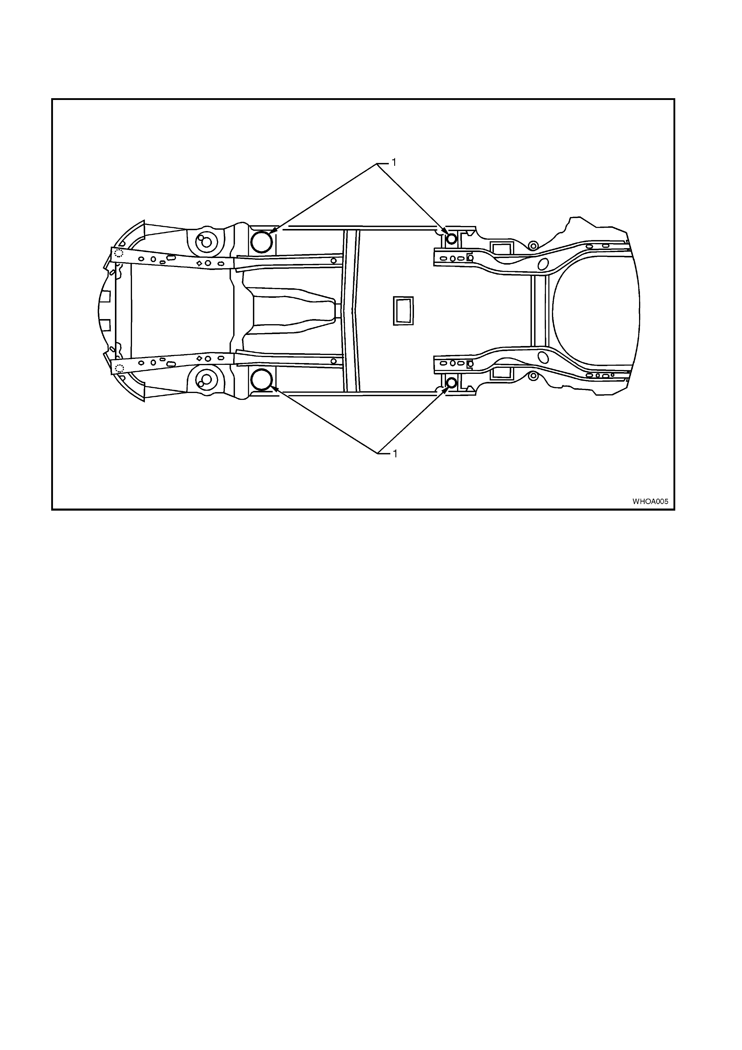
NOTE: When using a trolley jack to raise the vehicle it is important that the jack be positioned under the
suspension cross member or hoist pad locations (1). Do not jack under the suspension control arm. The
vehicle should always be supported by jack stands at the hoist pad locations when raised.
Figure 0A-1

2. MODEL AVAILABILITY AND BASE EQUIPM ENT
BODY MODEL NO.OF TRANSMISSION REAR
AXLE
STYLE NO. MODEL NAME DOORS ENGINE TYPE SHIFT
LOC.
RATIO
:1 TYRES WHEELS
Sedan 8WY19
8WZ19
Statesman
Caprice
43.8 PFI
5.7 PFI 4 Speed Auto Floor 3.08 215/60R
95V 7.J x 16
Alloy

3. POWERTRAIN COMBINATIONS
ENGINE TRANSMISSION
TYPE MODEL
AVAILABILITY FIRST GEAR
RATIO REAR AXLE RATIO :1
3.8 LITRE
PFI 4 Speed
Automatic Statesman Sedan
Caprice Sedan 3.059:1 3.08:1
3.8 LITRE
PFI
SUPERCHARGED
4 Speed
Automatic Statesman Sedan
Caprice Sedan 3.059:1 3.08:1
5.7 LITRE
PFI 4 Speed
Automatic Statesman Sedan
Caprice Sedan 3.059:1 3.08:1

4. TRANSMISSION RATIOS
4 SPEED
AUTOMATIC
1ST 3.059:1
2ND 1.63:1
3RD 1.000:1
4TH 0.7:1
5TH -
REV 2.3:1

5. ENGINE DATA
ENGINE
DESIGNATION 3.8
LITRE
PFI
3.8 LITRE
SUPERCHARGED 5.7 LITRE PFI
Piston Displacement
Nom. - cm33791 3791 5667
Compression Ratio 9.4:1 8.5:1 10.1:1
Number of Cylinders 6 6 8
Bore x Stroke - mm 96.5 X
86.3 96.5 X
86.3 99 X
92
Taxable H.P.
RAC OR SAE 34.7 34.7 48.6
Power kW
DIN @ RPM 147 kW
@ 5200 171 kW@ 5000
PULP* 220 kW
5200
Torque Nm
DIN @ RPM 304 Nm
@ 3600 375 Nm@ 3200
PULP* 446 Nm
@ 4000
*PULP - Premium Unleaded Petrol
6. EXTERIOR DIMENSIONS
SEDAN
BODY MODELS
DIMENSIONS 8WY19 8WZ19
VEHICLE LENGTH 5235 5235
VEHICLE WIDTH 1847 1847
VEHICLE HEIGHT 1447 1447
WHEELBASE 2939 2939
OVERHANG - FRONT 986 986
OVERHANG - REAR 1311 1311
TREAD - FRONT 1559 1559
TREAD - REAR 1576 1576

7. VEHICLE WEIGHTS
SEDAN
VEHICLE MODELS
WEIGHTS 8WY19 8WZ19
KERB MASS V6 1690 1695
KERB MASS V8 1732 1739
REAR AXLE LOAD V6 1149 1154
REAR AXLE LOAD V8 1157 1161
PAYLOAD (5 Pass. + Cargo) 408 408
NOTE: All figures are estimates only.
Payload figures must include luggage, goods,
passengers, roof rack load and a full tank of fuel. If
you are towing, then the weight on the tow bar ball
must also be included.
Maximum Rear Axle Load is maximum for all
conditions.
8. SERIAL NUMBERS
The complete vehicle and various components of the vehicle are identified by number plates or numbers
stamped into the part. It is essential that when compiling warranty claims or product and field reports, the
vehicle identification number (VIN) is quoted in conjunction with the identification number of the component
affected.
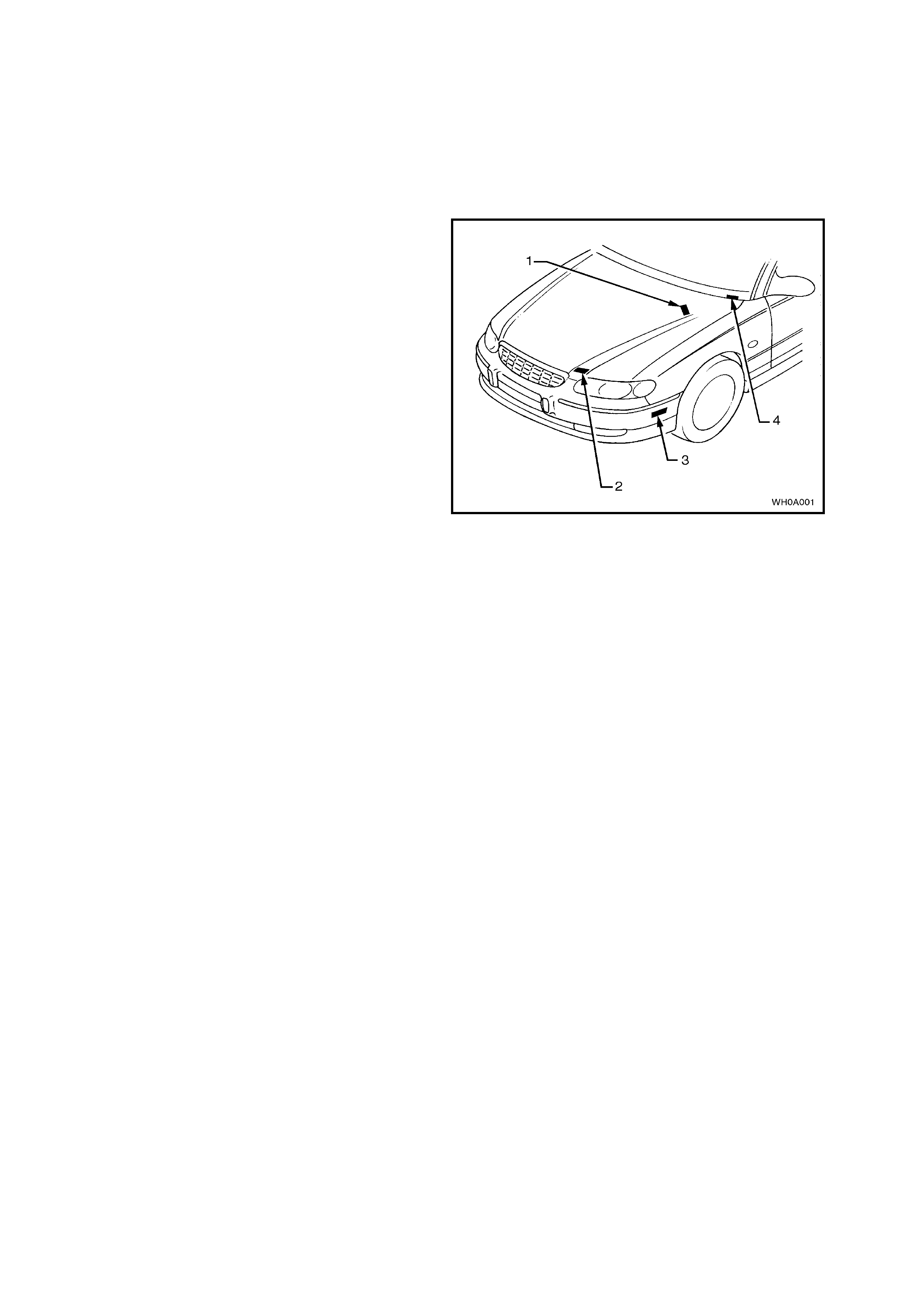
8.1 LOCATION OF IDENTIFICATION PLATES
Identification plates are attached to the upper right
side of the dash panel, front radiator s upport panel,
behind the bumper facia, and under the windshield
lower left corner, refer to Fig. 0A-2.
Legend
1. Safety Compliance Plate.
2. Body and Option Identification Plate.
3. Vehicle Identification Number Plate.
4. Vehicle Identification Number Plate.
Figure 0A-2
8.2 SAFETY COMPLIANCE PLATE (NOT APPLICABLE TO EXPORT)
Plate stamped with the following information:
Refer to Fig. 0A-3.
COMPLIANCE PLATE APPROVAL NUMBER.
VEHICLE CATEGORY CODE.
NAME APPEARING ON COMPLIANCE PLATE
APPROVAL.
MAKE/MODEL.
SEATING CAPACITY.
DATE OF MANUFACTURE
(* Variable information).
VEHICLE IDENTIFICATION NUMBER
(* Variable information). Figure 0A-3
Legend
1. Safety Compliance Plate.
Figure 0A-4
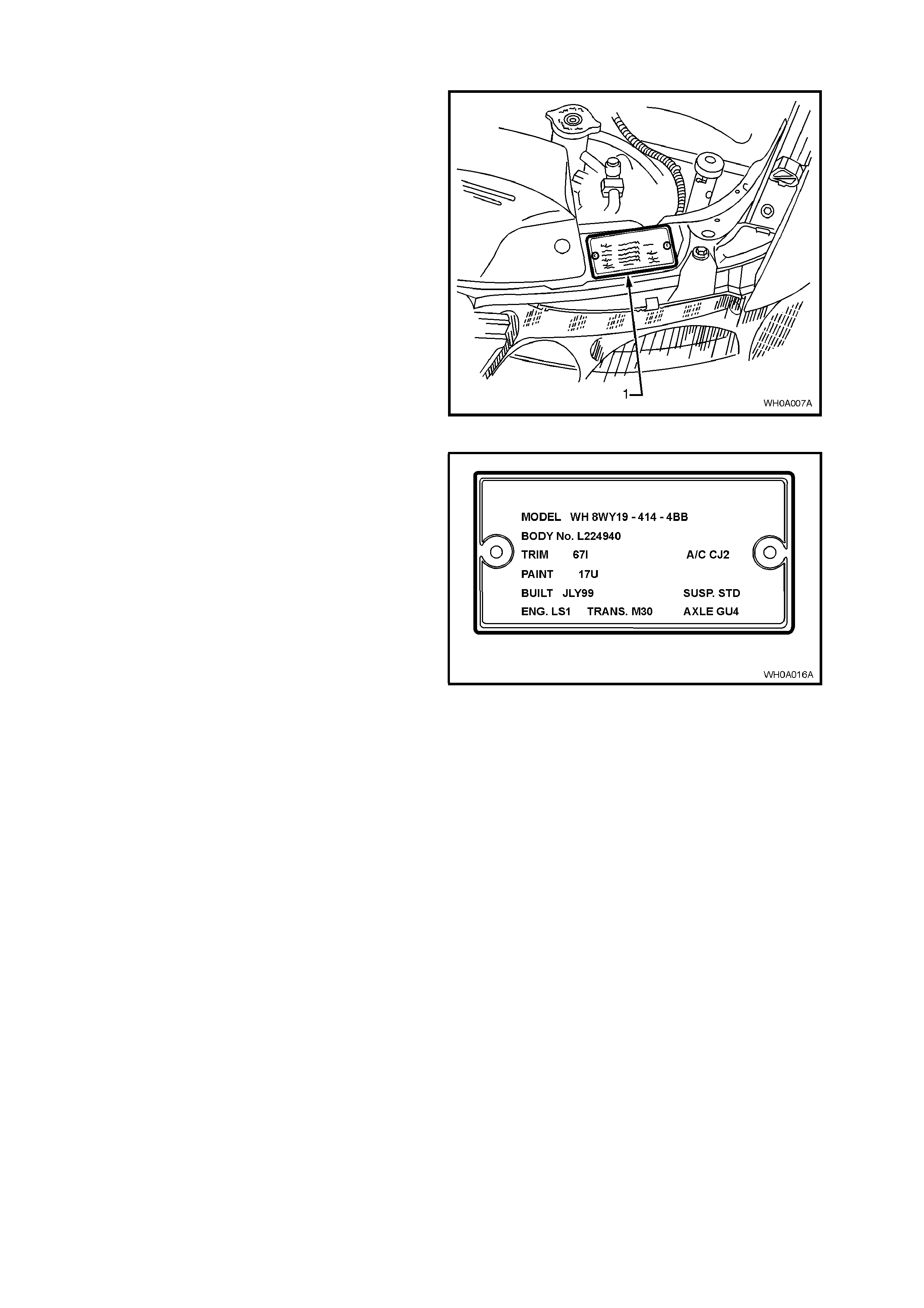
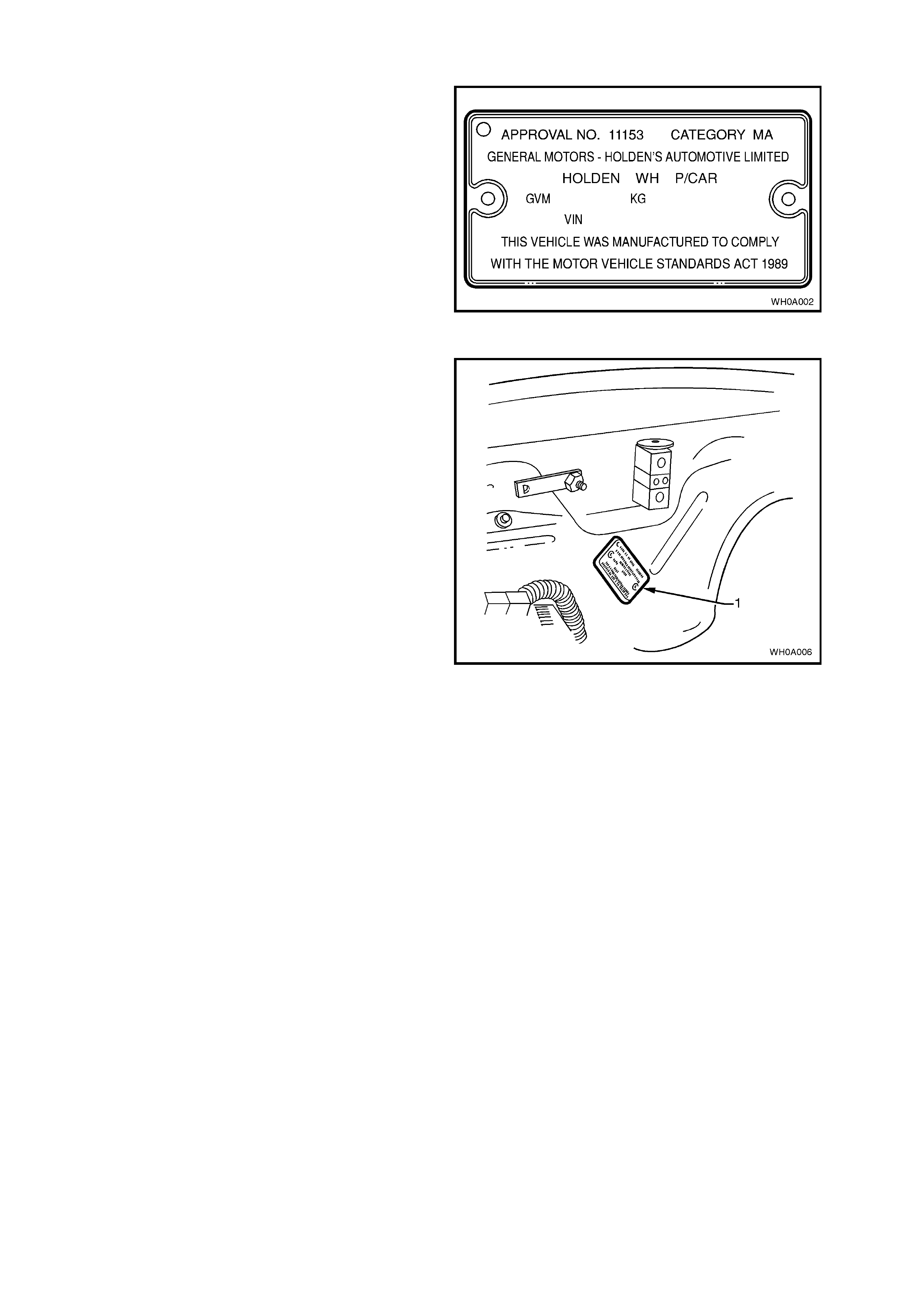
8.3 BODY AND OPTION IDENTIFICATION PLATE
The body and option identification plate (1) is
stamped with the following information, refer to
Fig. 0A-5.
Figure 0A-5
MODEL
Combination of letters and numbers identifying the
body style, the mechanical pack and smart pack
options.
NOTE: A listing of Production Option num bers and
Smart Pack Option numbers, can be found by
referring to the latest spare parts information (Part
Finder) for the applicable model.
BODY
Production build number, in continuous sequence
regardless of model, body type and series.
TRIM
Trim combination.
PAINT
Exterior paint material and colour identification.
BUILT
The date of manufacture by calendar month and
year in which the body shell and power train are
conjoined and the vehicle is driven or moved from
the production line.
SUSP
Suspension option code identification number, i.e.
FE2.
ENGINE, TRANSMISSION AND AXLE
Identification option codes for specific engine,
transmission and rear axle.
A/C
Identification option code CJ2 identifies vehicles
fitted with Dual Zone Electronic Climate Control air
conditioning.
Figure 0A-6
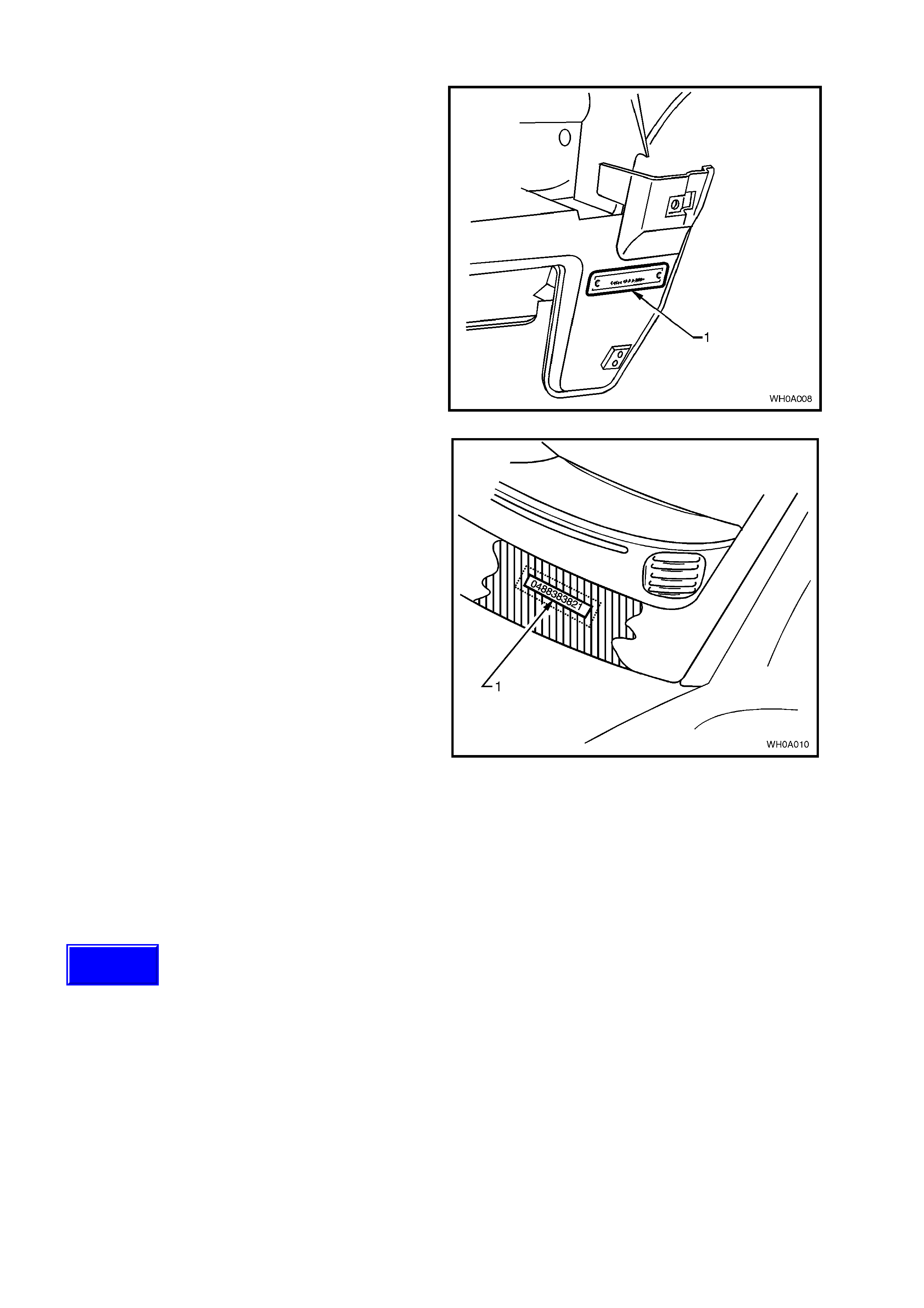
8.4 VEHICLE IDENTIFICATION NUMBER PLATE LOCATION (BODY LOCATION)
One of the vehicle identification number plates
(Body) (1) is located under the f ront bumper on the
left hand side.
Figure 0A-7
The second vehicle identification number plate
(Body) (1) is located under the windscreen and is
viewed through the windscreen aperture.
The VIN plate is secured to the body by unique
rosette headed rivets.
Figure 0A-8
8.5 VEHICLE IDENTIFICATION NUMBERING SYSTEM
For details of vehicle identification numbering (VIN) system, refer to Fig. 0A-9, on the following page.
Techline
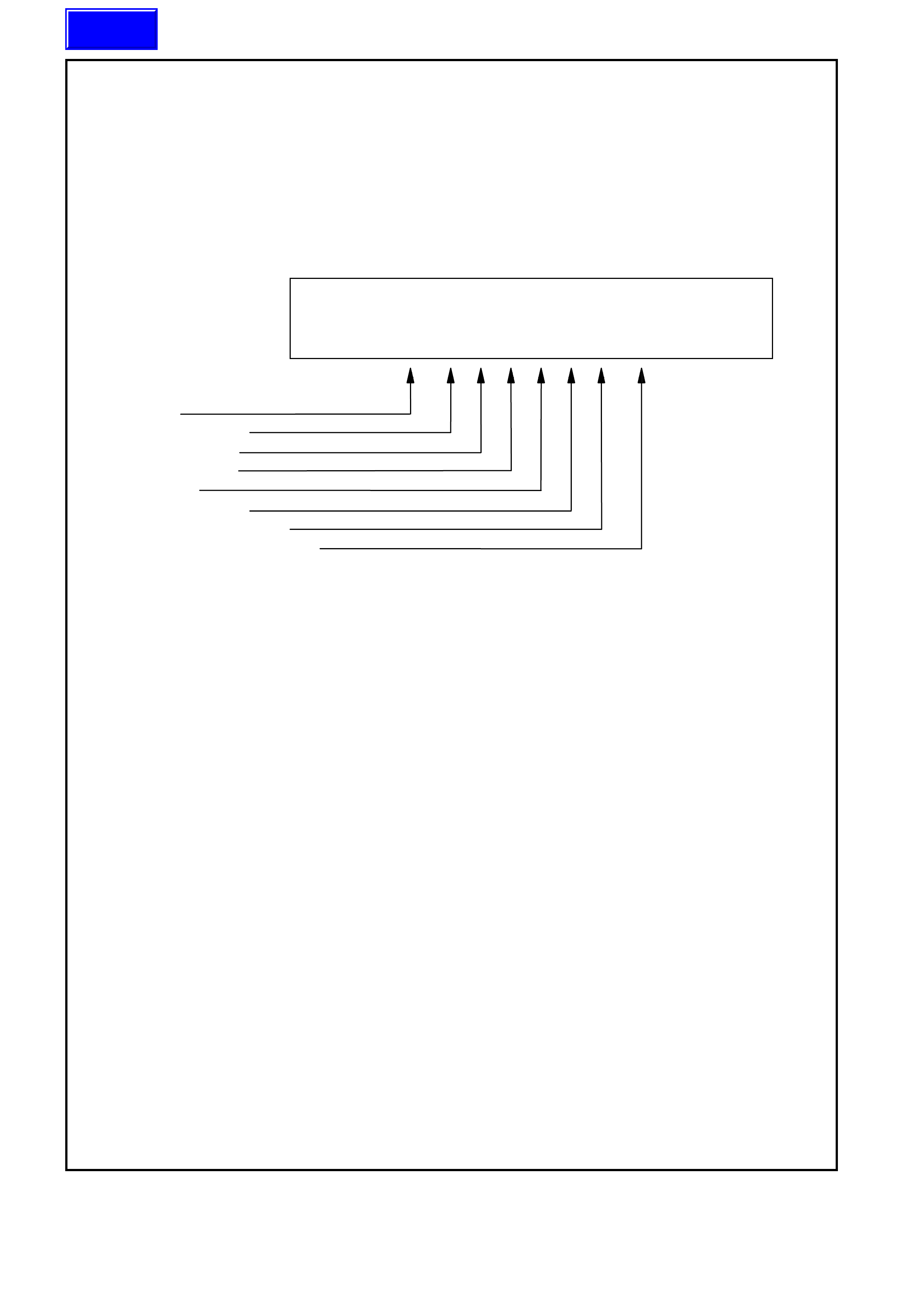
VEHICLE IDENTIFICATION NUMBERING SYSTEM
The Vehicle Identification Numbering System (VIN) is based on the uniform Car Model Designation
System. The reason for this is to identify the vehicle in one coded series of Characters.
The significance of these characters or blocks of characters are explained below, using as an example
identification number 6H8 WH Y 19 H V L 123456.
MODEL DESIGNATION
WMI Code
Model Series Code
Degree of Luxury
BODY STYLE CODE
ENGINE CODE
MODEL YEAR CODE
ASSEMBLY PLANT CODE
SERIAL SEQUENCE NUMBER
6H8 WH Y 19 F X L 123456
MODEL DESIGNATION
WMI Code – 6H8 – World manufacturer’s identifier allocated to Holden
Model Series Code - WH = WH Series
Degree of Lux ury - Y – STATESMAN
- Z – CAPRICE
Body Style Code - 19 – Sedan
ENGINE CODE
Engine Identification Code (H – signifies 3.8 engine, S – signifies 3.8 supercharged engine,
F – signifies 5.7 engine)
MODEL YEAR CODE
X – Identifies Model Year X = 1999
Y = 2000
This Letter relates to GM Internal Operation Only.
ASSEMBLY PLANT CODE
Australian Assembly Plant Identification Code:-
L – Adelaide (Elizabeth)
SERIAL (Sequence ) NUMBER
123456 – Sequential Production Serial Number
NOTE: This designates the Serial Unit Number at the Vehicle Plant, starting at
(00001) and continues in Numerical Sequence regardless of vehicle type.
Figure 0A-9
Techline
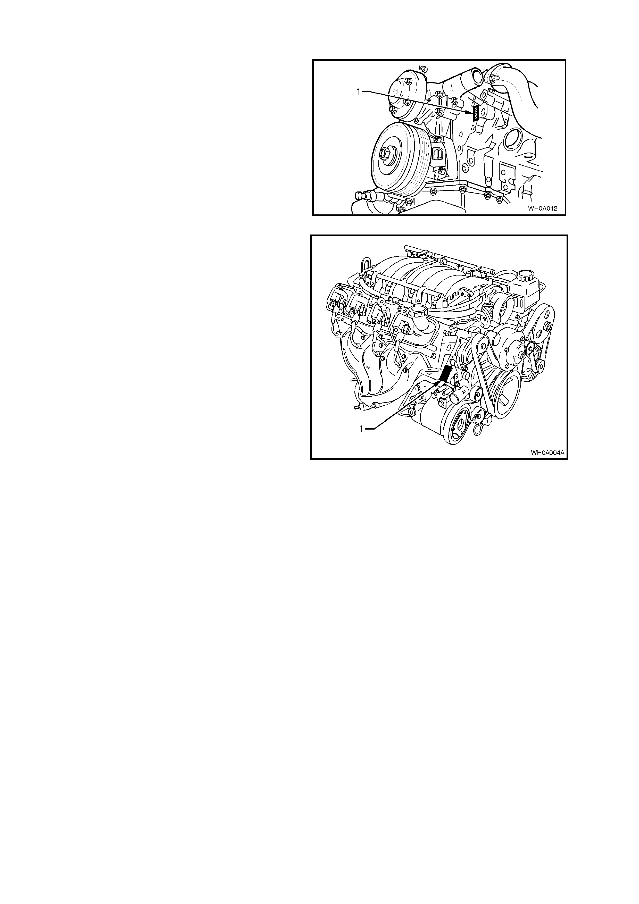
8.6 ENGINE SERIAL NUMBER
The engine number (1) for the 3.8 V6 engine is
stamped on the front face of the engine, below the
ignition coil as illustrated in Fig.0A-10.
Figure 0A-10
The 5.7 litre GEN III V8 engine number (1) is
stamped on a pad located adjacent to the engine
coolant outlet pipe. Refer to Fig. 0A-11.
The engine number is prefixed by the letters 'VF'.
Figure 0A-11
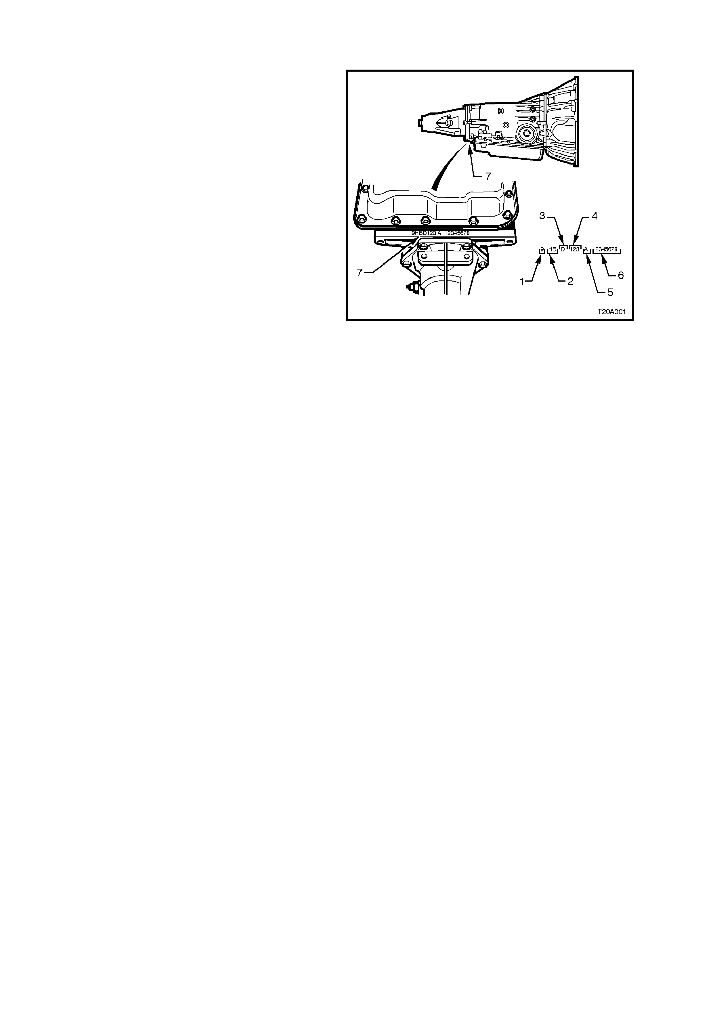
8.7 AUTOMATIC TRANSMISSION SERIAL NUMBER
The automatic transmission serial number is
stamped into a machined surface at the rear
underside of the transmission centre case, refer to
Fig. 0A-12.
Legend
1. Model Year (‘9’ = 1999)
2. Model: V8 – 5.7 litre GEN III HP
V6 – 3.8 litre HF
V6 Supercharged –
3.8 litre HN
3. Transmission Model Identifier (D = 4L60-E)
4. Julian Date (or day of year)
5. Shift Built (A, B, J = first shift; C, H, W =
second shift)
6. Individual Transmission Serial Number
7. Transmission Identification Number
Location Figure 0A-12

8.8 REAR AXLE IDENTIFICATION
An identification tag ( 1) is adhered to the final drive
assembly to the RHS of the car rier housing, ref er to
Fig.
0A-13. The tag carries the Holden part number for
the axle assembly, the final drive ratio and the
serial number of the axle assembly.
Figure 0A-13
9. ADDI TIONAL GENERAL I NFORMATION
9.1 ELECTRICAL TRANSIENTS AND RADIO FREQUENCY INTERFERENCE
Electronic circuits are used in WH Models to perform a number of functions associated with electronic
cruise control, electronic engine and transmission control systems etc. These circuits can be damaged or
malfunction as a result of electrical transients or excessive radio frequency (RF) radiation.
ELECTRICAL TRANSIENTS
Electrical transients are high voltage spikes, produced by the sudden switching or interruption of electric
currents. Older style timing lights and battery chargers can produce serious transients, hence, it is
important to use only good quality equipment suitable for use with electronic systems.
It is also good practice to ensure that the battery is disconnected before using a battery charger.
Indiscriminate fitting of solenoids, indicators or relays can also cause transients.
RADIO FREQUENCY INTERFERENCE
One of the chief sources of RF interference is the ignition system. Other sources include CB radio and
radio telephones. The following are normally used to suppress RF interference.
Resistors eg. High Tension Cables and Connectors.
Capacitors and Choke Coils.
Metal Braid for screening leads or suppression covers made from conductive material for screening
equipment.
To prevent damage to equipment:
Do not replace interference suppressed high tension ignition cables or connectors with unsuppressed
types.
Do not remove or reposition interference suppression filters or capacitors.
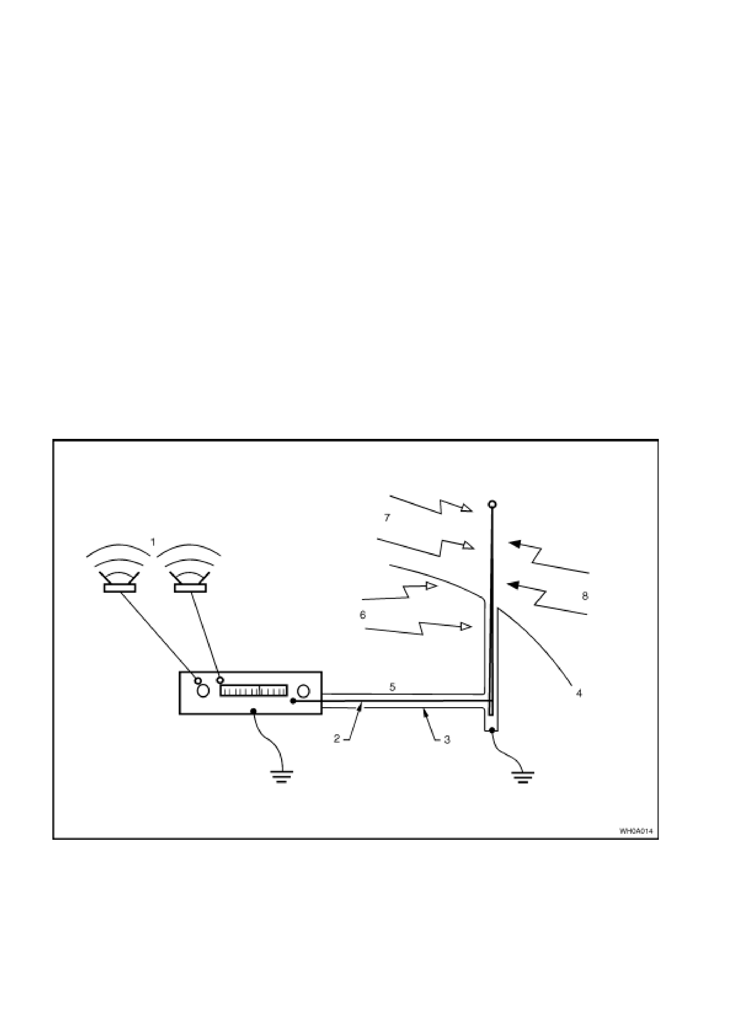
Figure 0A-14
Legend
1. Music.
2. Core.
3. Braid.
4. Body.
5. Antenna cable.
6. Internal Interference.
7. Signal from station.
8. External interference.

9.2 STATIC ELECTRICITY
Care should be exercised when handling electronic equipment e.g. the electronic control module (ECM), to
avoid touching the terminals unnecessarily. Static electricity, which is present on every person, can cause
damage to some electronic components.
9.3 PUSH OR TOW STARTING
Do not push or tow start WH Series vehicles. Push or tow starting can result in unburned fuel passing
through the exhaust to the catalytic converter, causing damage to the converter.