
SECTION 4A - INDEPENDENT REAR SUSPENSION
IMPORTANT
Before performing any Service Operation or other procedure described in this Section, refer to
Section 00 CAUTIONS AND NOTES for correct workshop practices with regard to safety and/or
property damage.
1. GENERAL INFORMA TION
Both WH Statesman and Caprice vehicles are fitted with an automatic level ride system as standard equipment.
Apart from this feature, minor revisions to suspension component specifications to reflect the introduction of the
GEN III V8 engine and to optimise vehicle handling characteristics, are included in this Section, in their entirety.
All other service operations remain as detailed in Section 4A INDEPENDENT REAR SUSPENSION of the VT
Series I Service Information.
Techline
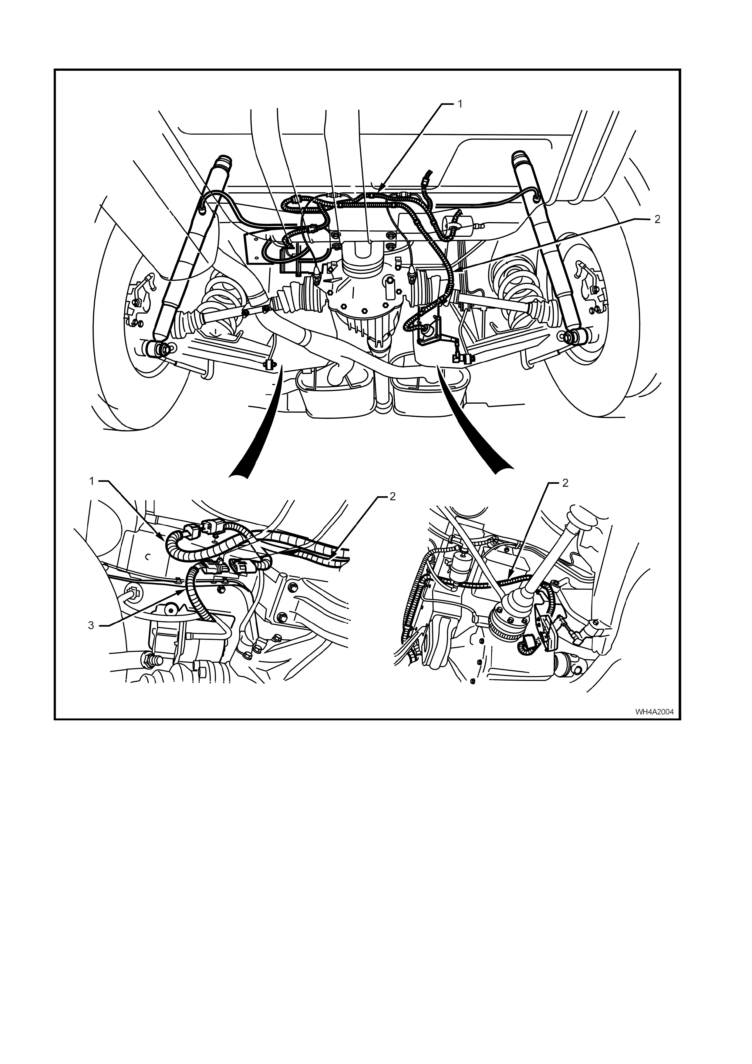
2. GENERAL DESCRIPTION
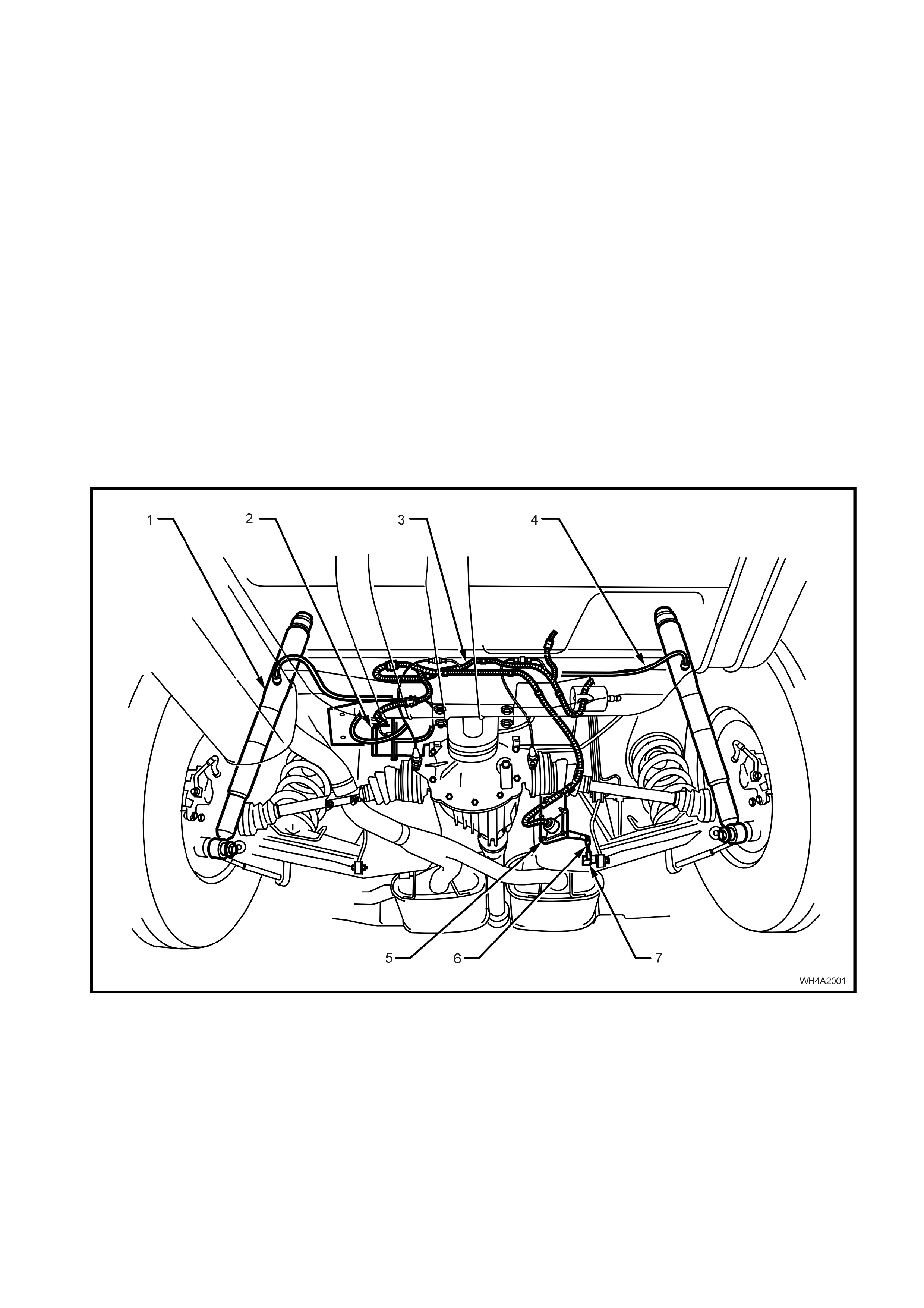
Automatic level ride is an electronically controlled system that maintains the vehicle at a constant trim height,
regardless of vehicle load. This feature uses a specifically designed electronic ride height sensor (5), fixed to the
rear crossmember on the right hand side. This sensor controls an electric motor driving a single cylinder air
compr ess or (2) and a n ex h aus t sol eno id v al ve. T he c ompress or (2) suppli es th e n ec es sary pressur e t o o per a te the
“Superlif t” shock absorber s (1) v ia “snap o n” air li nes (4) . The “Sup erlift” shock absorbers ass ist the rear s prings in
supporting the vehicle body under all loads.
The ride height sens or (5) has an integr ated electro nic controller that is pr ogramm ed to adjust the ride heig ht only
when necessary, ignoring sudden changes, as experienced on bumpy roads. The design of the system maintains
trim at all times when the ignition is on. As a safeguard to prevent the battery discharging, an electronic timer
switches off the compressor if it runs for a prolonged period (i.e. due to an air leak in the system).
The compressor assembly includes a maximum pressure release valve and an air drier. All air entering or
exhausting the system flows through the drier, which has an internal minimum retention valve preventing the air
bag, surrounding each shock absorber, from com pletely exhausting, indepen dent of the sensor controlled exhaust
valve.
Electric power to operate the system is supplied by an integrated wiring harness (3).
There are two main benefits resulting from the automatic level ride feature:
• Headlamp aim and rear view mirror adjustment being maintained independent of load.
• Rear tyre camber and toe-in are held to their optimum alignment to minimise tyre wear.
NOTE: If air pressure is lost from the system while the vehicle is in service (e.g. an air leak), the Superlift shock
absorber air bag wil l ver y pr obab ly be dam aged, re quir ing re plac ement.
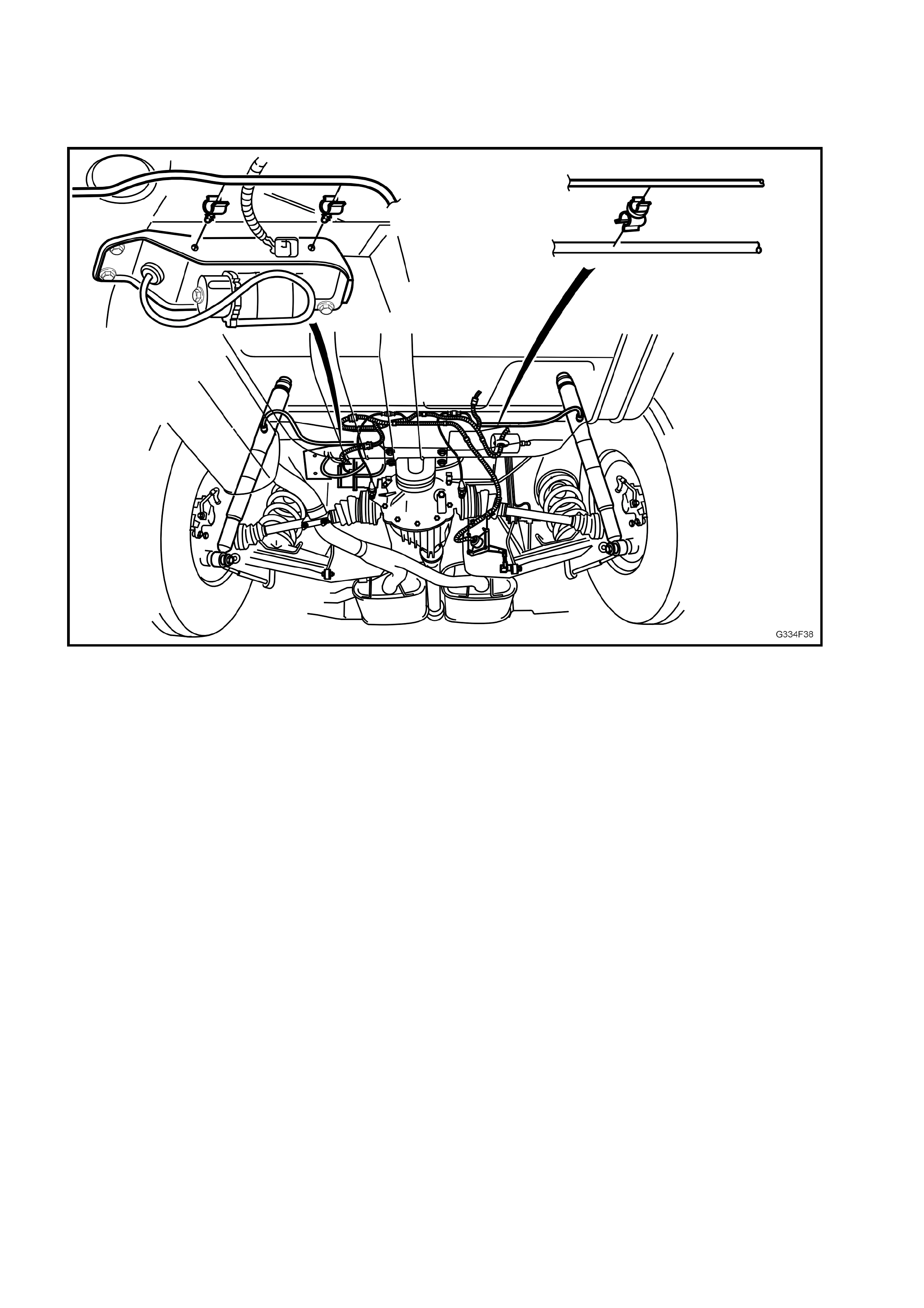
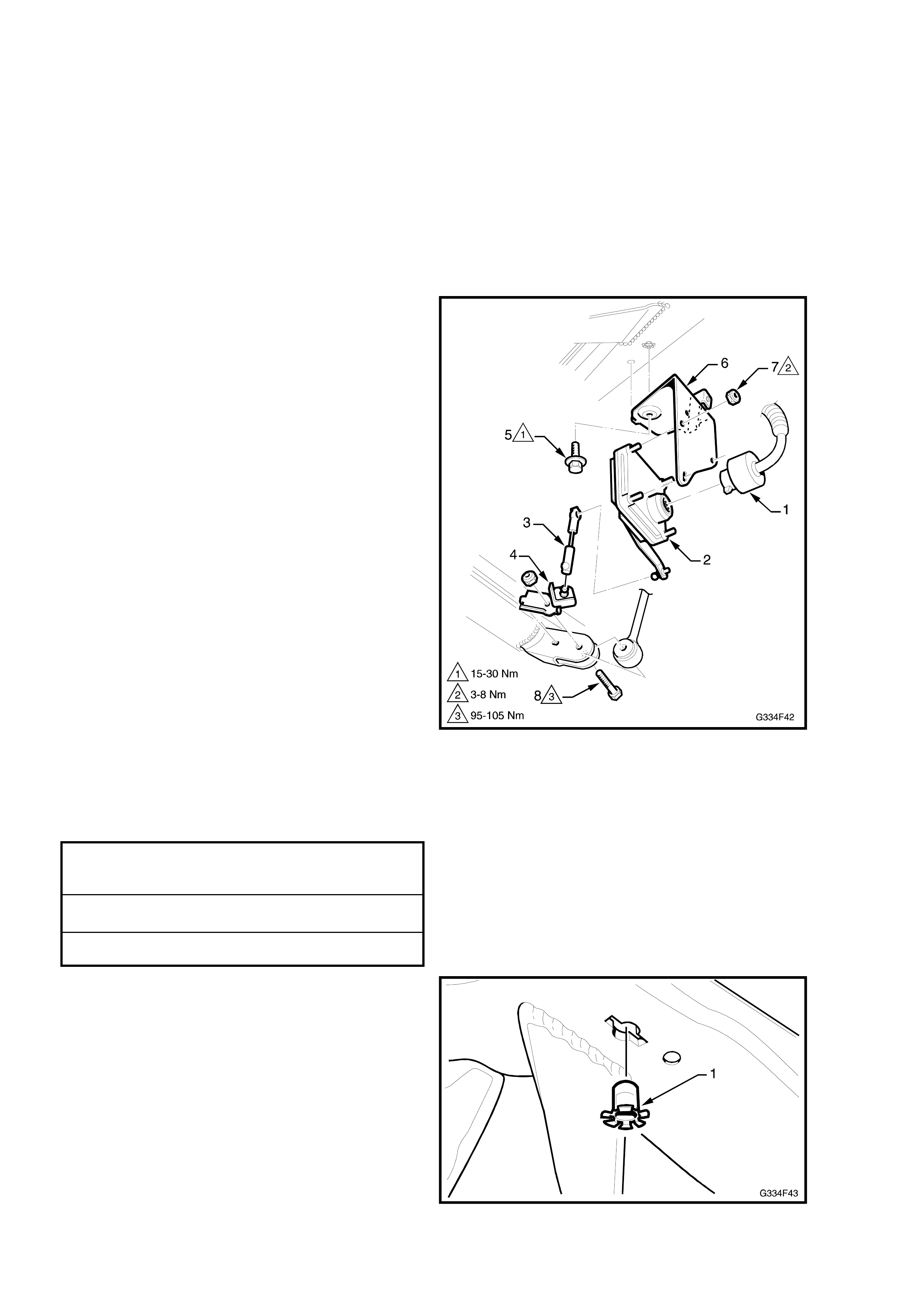
1. Superlift Shock Absorbers 5. Ride Height Sensor
2. Air Compressor Assembly 6. Ride Height Sensor Connecting Link
3. Level Ride Wiring Harness 7. Ride Height Sensor Ball Stud Plate
4. Air Lines
Figure 4A-1
2.1 SYSTEM OPERATION
ACTIVATION
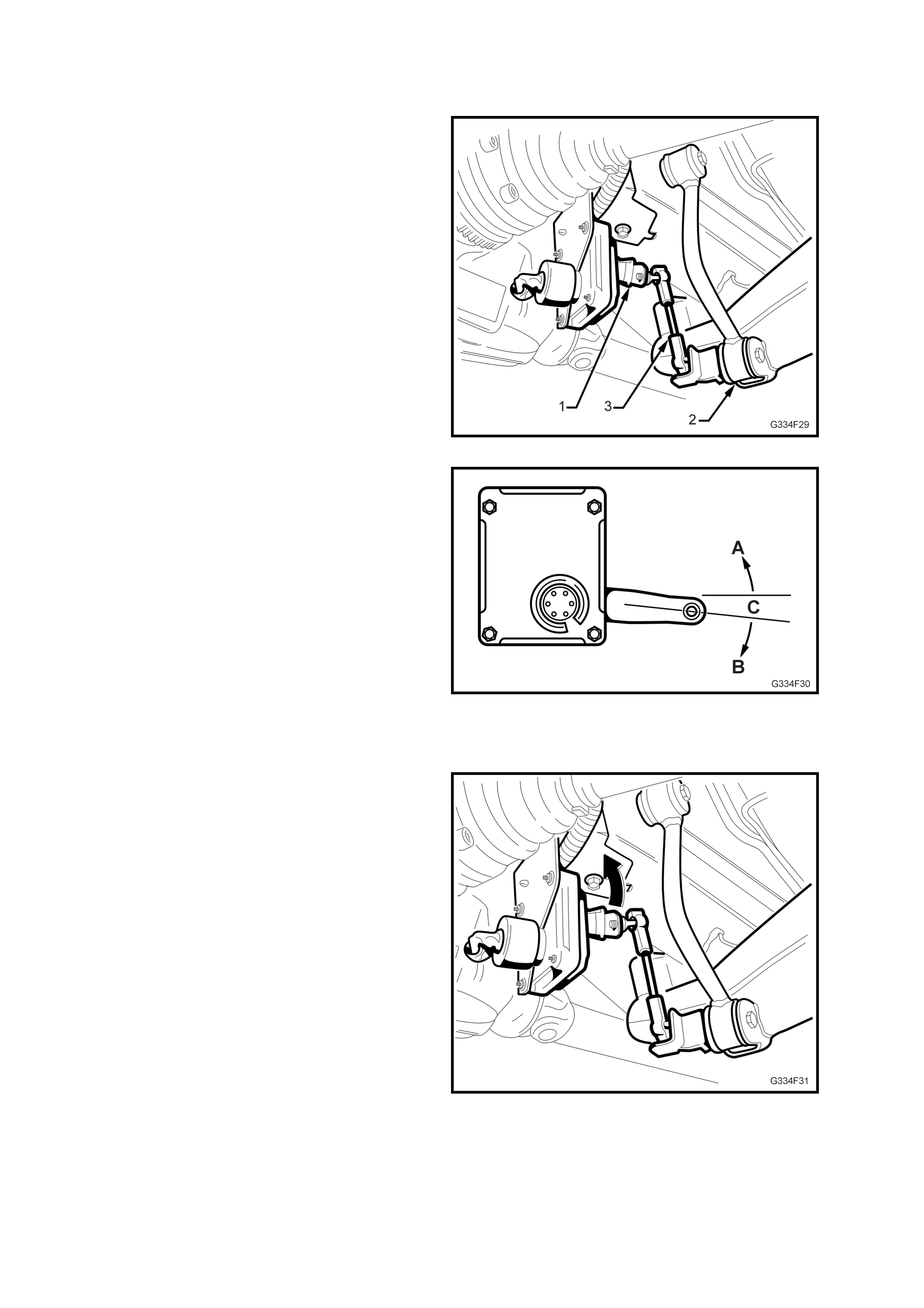
The sensor’s actuating arm (1) is attached to the
lower control arm (2) via a connecting link (3).
Figure 4A-2
Before any activation can occur, the actuating arm
must remain in either the intake (A) or exhaust
zone (B) for a appr oxim ately 2 0 sec onds . T his tim e
delay prevents the compressor or exhaust valve
from activating when the vehicle encounters
sudden bumps.
Another stability feature is a ‘deadband’ zone (C),
that helps to minimise hunting, by deactivating the
compressor and solenoid when the vehicle trim
goes into or onto the deadband zone or one of its
edges.
Figure 4A-3
LO ADED VEHICL E
When the vehicle is loaded, the vehicle body
moves downward into the intake zone, causing the
actuating arm to move upwards (arrow).
After appr oximatel y 20 seconds in th is position, th e
sensor relieves the compressor head pressure by
briefly activating the compressor relay. The
compressor starts and pressurises the Superlift
shock absorbers until the vehicle body aligns with
the bottom edge of the deadband, at which point
the compressor stops.
Figure 4A-4
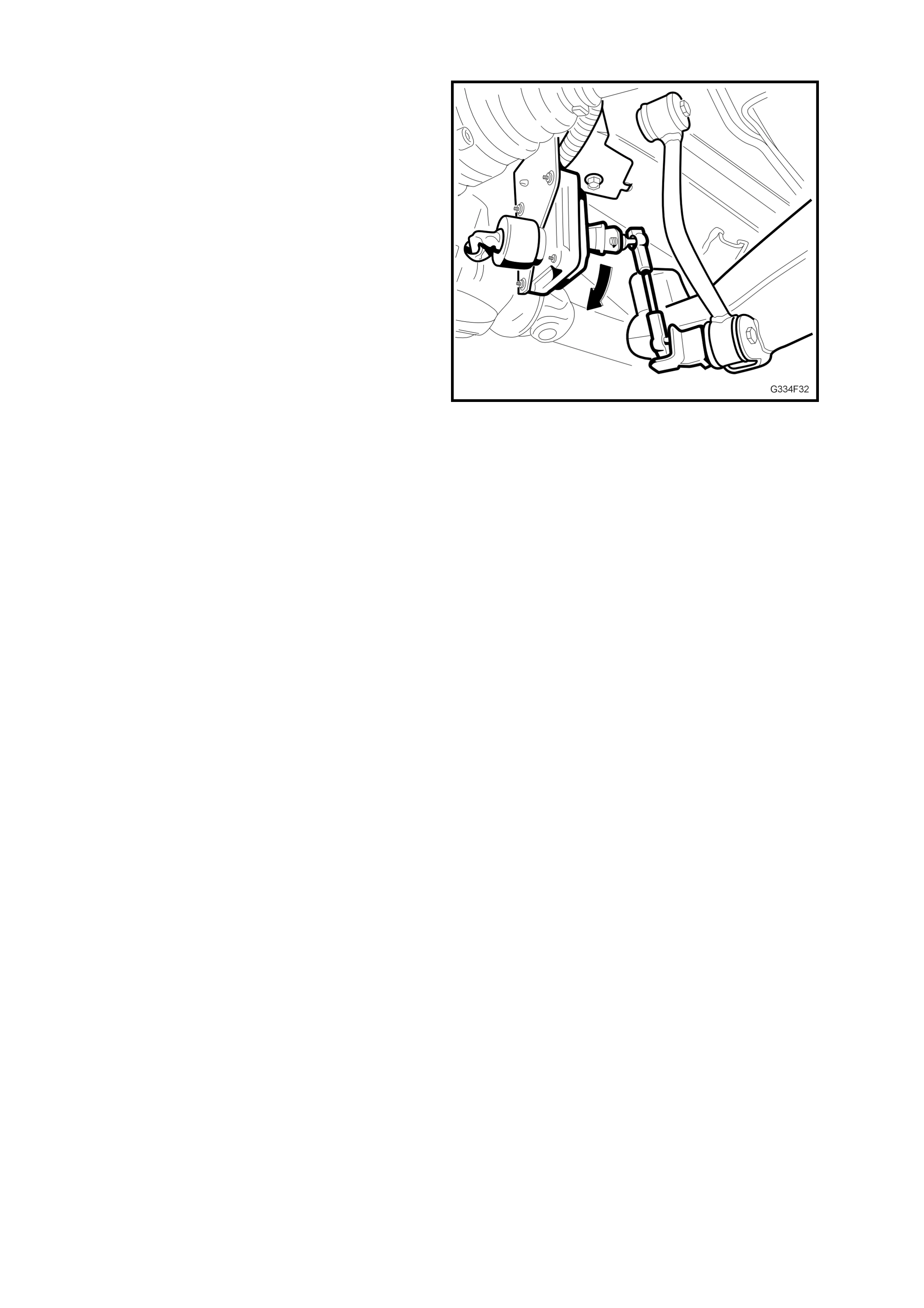
UNLOADED VEHICLE
When the vehicle is unloaded, the vehicle body
moves upward into the exhaust zone, causing the
actuating arm to move downwards.
After appr oximatel y 20 seconds in th is position, th e
sensor activates the exhaust relay. The exhaust
solenoid activates and vents pressure from the
Superlift shock absorbers until the vehicle body
aligns with the top ed ge of the deadban d, at which
point the solenoid deactivates.
Figure 4A-5
DEACTIVATION
The compressor and exhaust solenoid operations
are monitored and controlled by individual but
interconnected timers. The timers deactivate
specific trimming operations under the following
conditions:
• If the compressor runs for a cumulative time of
more than four and a half minutes, the
compressor timer deactivates all system
operations.
• If the exhaust solenoid is active for a cumulative
time of more than four and a half minutes, the
solenoid timer deactivates the solenoid.
No further operati on of these com ponents can t ake
place until the timers are reset.
RESET PROCEDURE
The procedure to reset the timers is;
1. Turn the ignition ON.
2. Turn the ignition OFF for one minute.
3. Turn the ignition ON, once more to complete
the operation.
3. SERVICE MAINTENANCE OPERATIONS
3.1 MAINTENANCE
The lev el ride s ystem has been designe d to be virtu all y maintenanc e fr ee. Ho wever at each sc hedul ed serv ice, th e
following components must be inspected and rectified if found to be faulty.
AIR LINES
Inspect t he air lines f or rubbing or foul ing with the bo d y a nd ot her componen ts . E nsur e th e li nes are not kinked and
that they are fitted into the retaining clips. Check the connections for correct fit.
WIRING HARNESS
Inspect the wiring harness for rubbing or fouling with the body and other components. Ensure that it is fitted and
secured into the retaining clips and/or cable ties. Check the connections for correct fit.
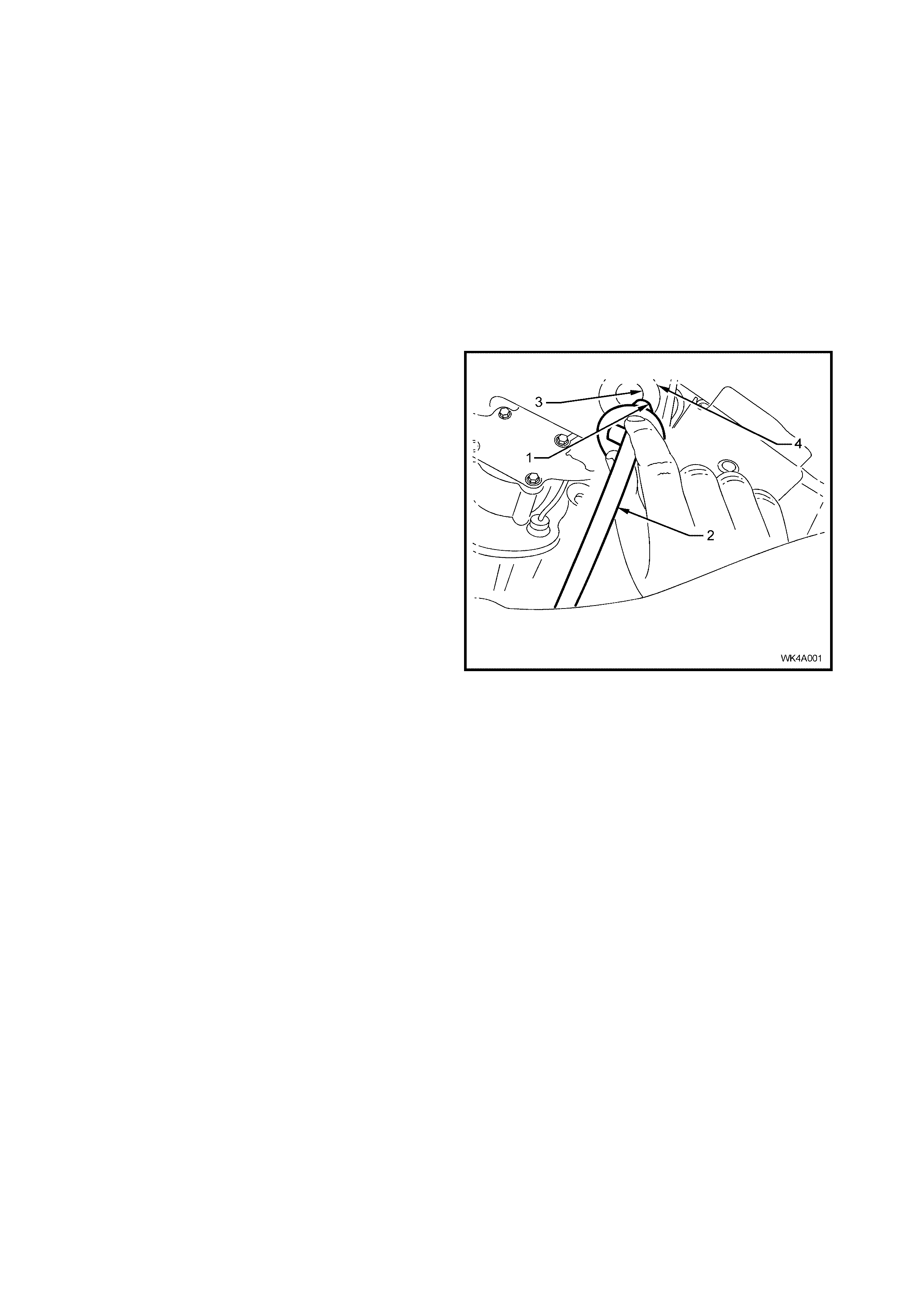
AIR FILTER
The compressor air filter (1) should be replaced at the
scheduled service intervals set down in the Owner’s
handbook. Inspect and replace more frequently if
required, where the vehicle is driven in dusty
conditions.
To service the compressor air filter, depress the two
lock ing tabs on t he cli p r eta ining the air intak e hos e ( 2)
and filter to the hole (3) in the compressor mounting
bracket (4) and withdraw the filter.
Tes t that the filter is clea n and free f rom restric tions b y
rem oving th e f ilter f orm the tube and blowin g thr o ugh it
from the hose connection end. If any restriction is felt,
replace the filter .
Figure 4A-6
4. SERVICE OPERATIONS
IMPORTANT: If air pressure in the level ride system is lost during service procedures, do not lower the
vehicle until system pressure has been restored, as damage will most likely result. Charge the system as
detailed in 4.1 INITIAL AIR CHARGE.
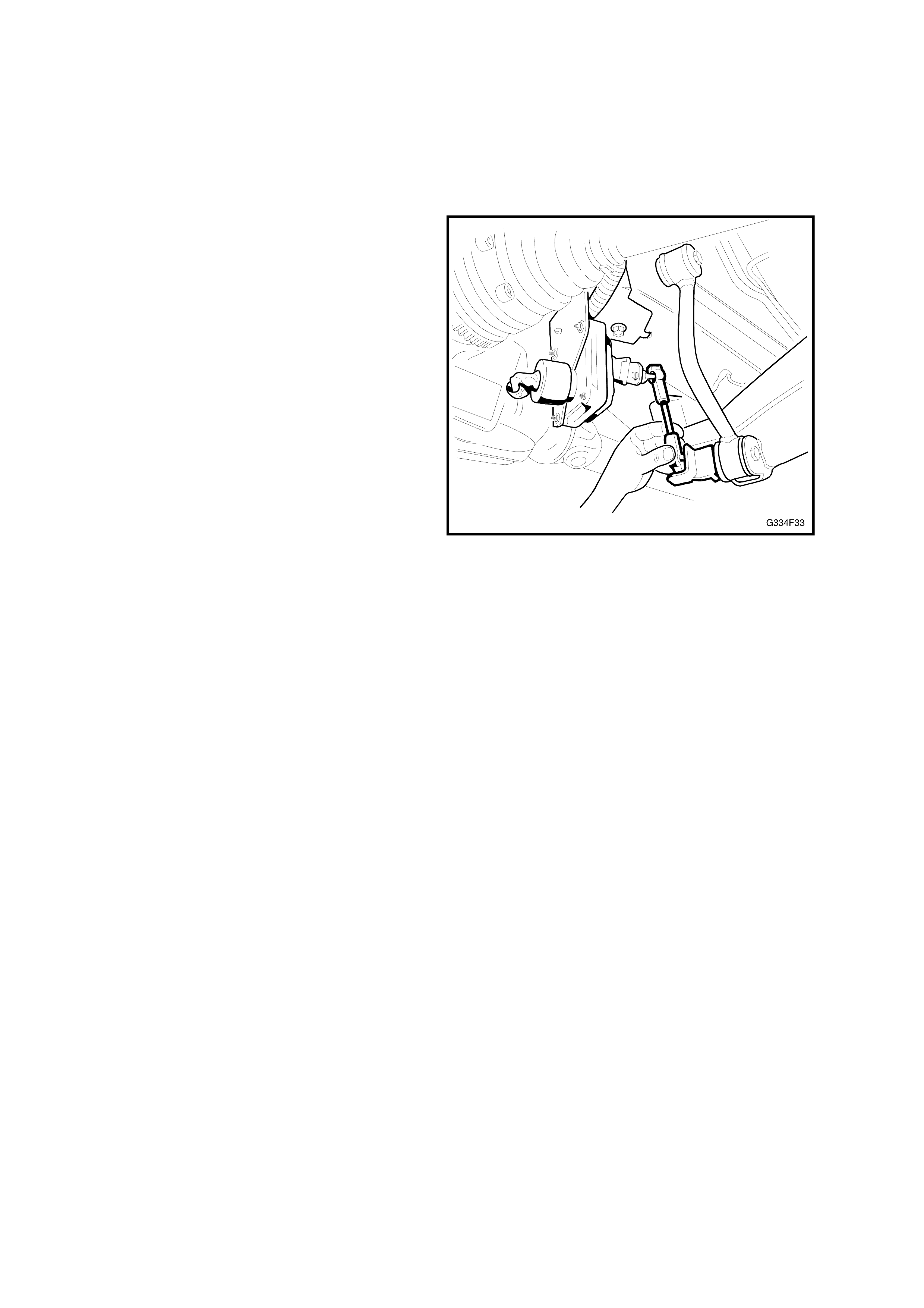
4.1 INITIAL AIR CHARGE
1. Turn the ignition on.
2. Disconnect the lower end of the sensor
connecting li nk.
3. Push the sensor arm upward, above the
horizontal plane for approximately 20 seconds,
until the compressor is activated.
4. Leave the compressor running for
approximately 30 seconds to inflate the
superlift shock absorbers.
5. Turn the ignition off.
6. Check the system for leaks.
7. Reconnect the sensor connecting link.
Figure 4A-7

4.2 AIR LEAK TEST
1. Ensure the system is pressurised. Refer to
4.1 INITIAL AIR CHARGE procedure if
required.
2. Starting at the shock absorber connections,
apply a foaming leak check solution
(commercially available, or a soap solution
mixed with water) to all fittings and
connections.
3. Carefully inspect the fittings and connections
for the presence of air bubbles in the solution.
4. Repair any detected leaks as required.
5. Retest the system for air leaks.
6. If air still leaks from the system, isolate sections
of the system until the source of the leak is
found.
7. Clean off the residual solution.
Figure 4A-8
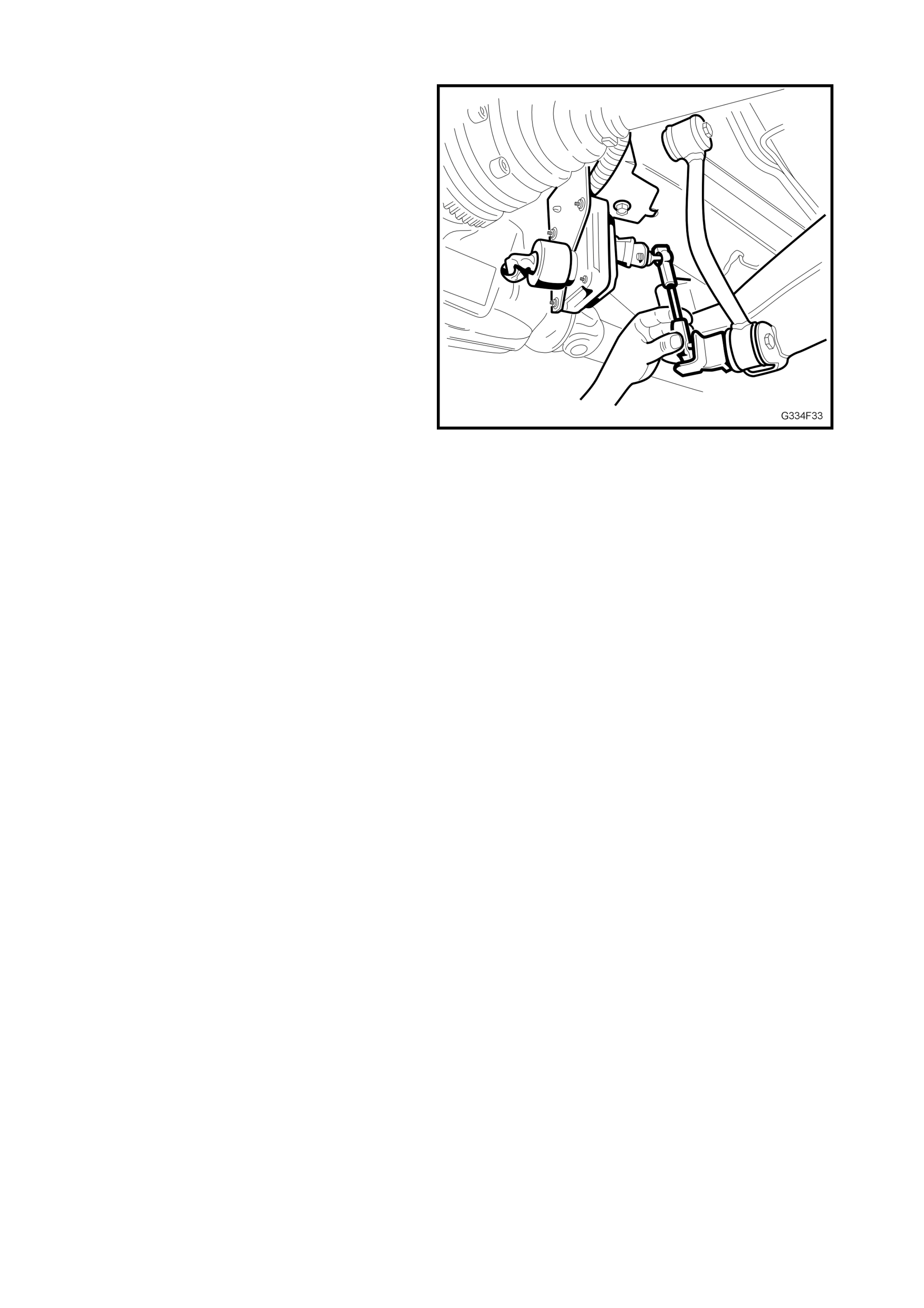
4.3 RELIEVING SYSTEM AIR PRESSURE
Prior to car rying out s ervic e operatio ns on the le vel
ride suspension system where the air pressure in
the system needs to be released, the following
procedure must be followed.
1. With the rear of the vehicle raised and
supported on safety stands under the trailing
arms, turn the ignition on.
2. Disconnect the lower end of the sensor
connecting li nk.
3. Pull the sensor arm downward, below the
horizontal plane and hold until the exhaust
solenoid is activated.
4. Maintain the sensor lever position, allow the
exhaust solenoid to remain active for
approximately 30 seconds to relieve the
system air pressure or until no sound of
exhausti ng air remains.
NOTE: Do not leave the sensor lever in the
lowered position for more than four and a half
minutes (with the ignition on), otherwise the
solenoid timer will deactivate the solenoid and the
timer must then be reset.
5. Turn the ignition off.
6. Proceed with service operations as required.
NOTE: After ser vice work has been com pleted , the
system pressure must be reinstated before
lowering the vehicle. Refer 4.1 INITIAL AIR
CHARGE in this Section for the procedure.
Figure 4A-9
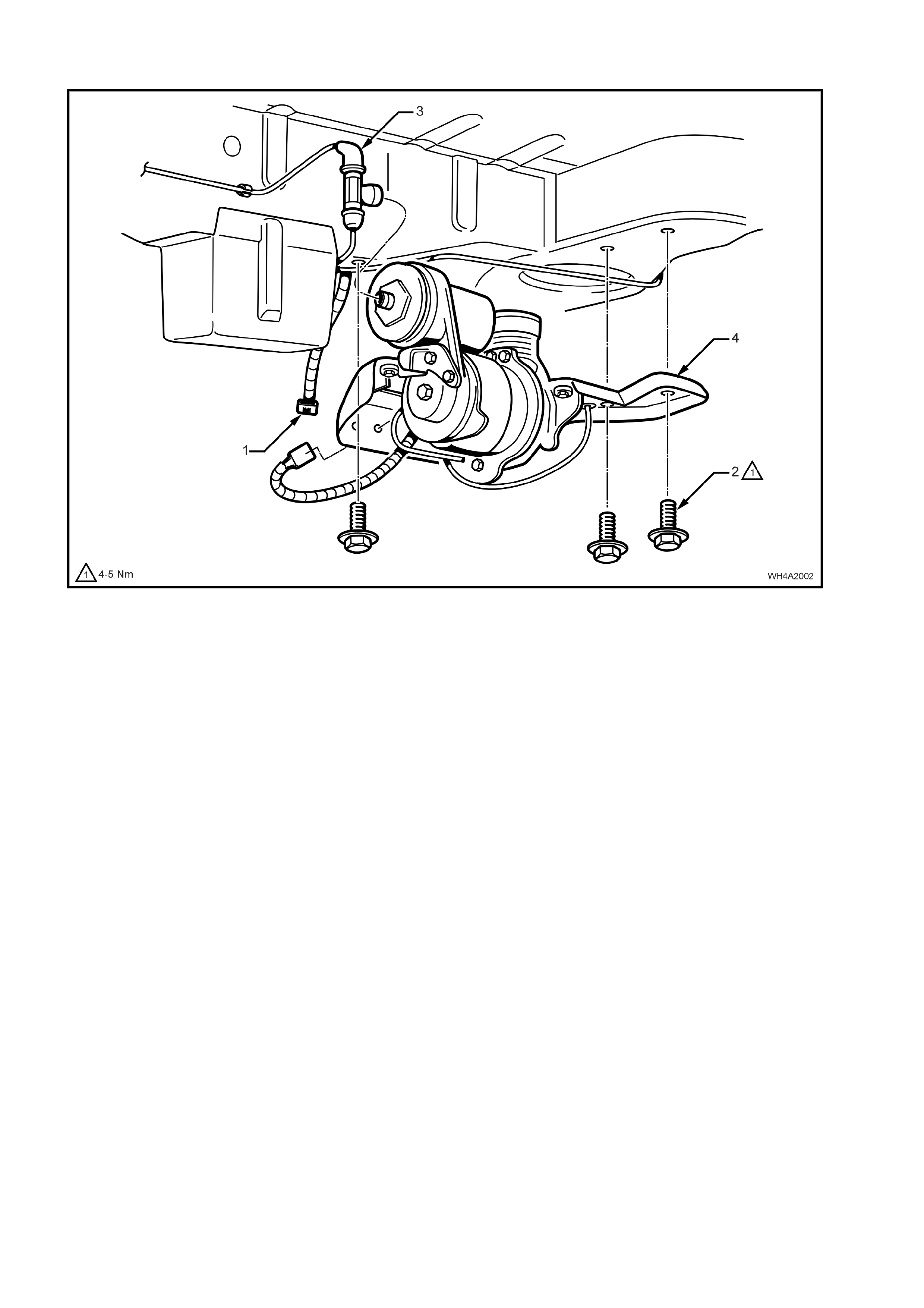
4.4 COMPRESSOR ASSEMBLY
Figure 4A-10
REMOVE
1. Disconnect the battery, negati ve lea d firs t.
2. Raise the vehicle.
3. Relieve system air pressure. Refer
4.3 RELIEVING SYSTEM AIR PRESSURE, in
this Section.
4. Unclip the level ride wiring harness (1) from
the com pr ess or ass em bl y mounting br ac k et ( 4)
and disconnect the wiring connector, refer
Fig. 4A-10.
5. Remove the three bolts (2) attaching the
compressor assembly mounting bracket (4) to
the vehicle body.
NOTE: Support the compressor assembly. Do not
allow it to drop.
6. Disconnect t he airline T -connector (3) f rom the
compressor by rotating the T-piece 90
degrees, then gently pulling it away from the
compressor.
7. Lower the compressor assembly.
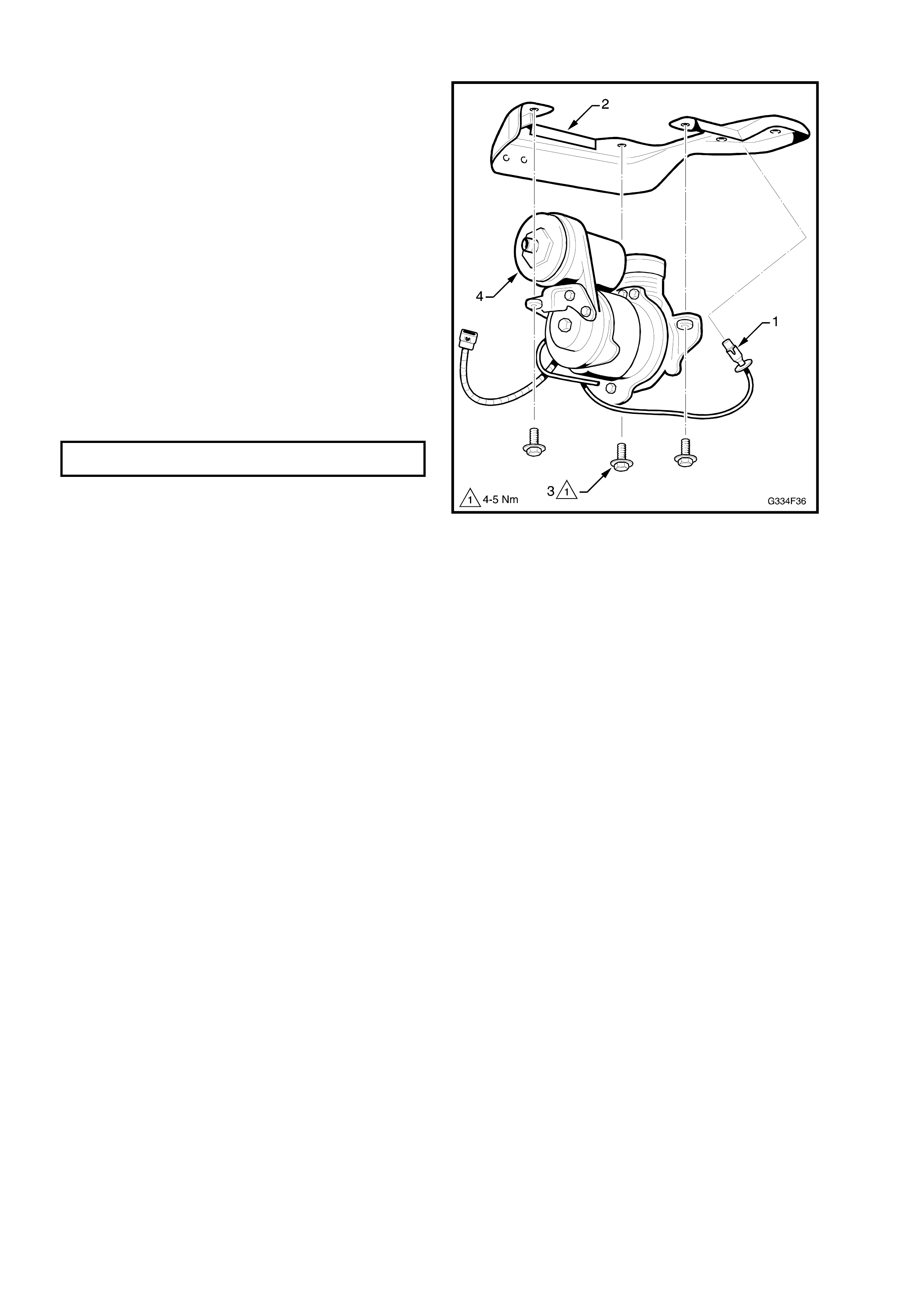
DISASSEMBLE
1. Remove the filter (1) from the mounting bracket
(2).
2. Remove the three bolts (3) attaching the
compressor (4) to the mounting bracket.
3. Test that the filter is clean and free from
restrictions b y rem oving the f ilter form the tube
and blowing through it from the hose
connection e nd. If any restr ictio n is f elt, replac e
the filter.
REASSEMBLE
1. Install the components in the reverse order to
disassembly.
2. Tighten the bolts to the specified torque.
COMPRESSOR MOUNTING BOLTS 4-5
TORQUE SPECIFICATION Nm
Figure 4A-11
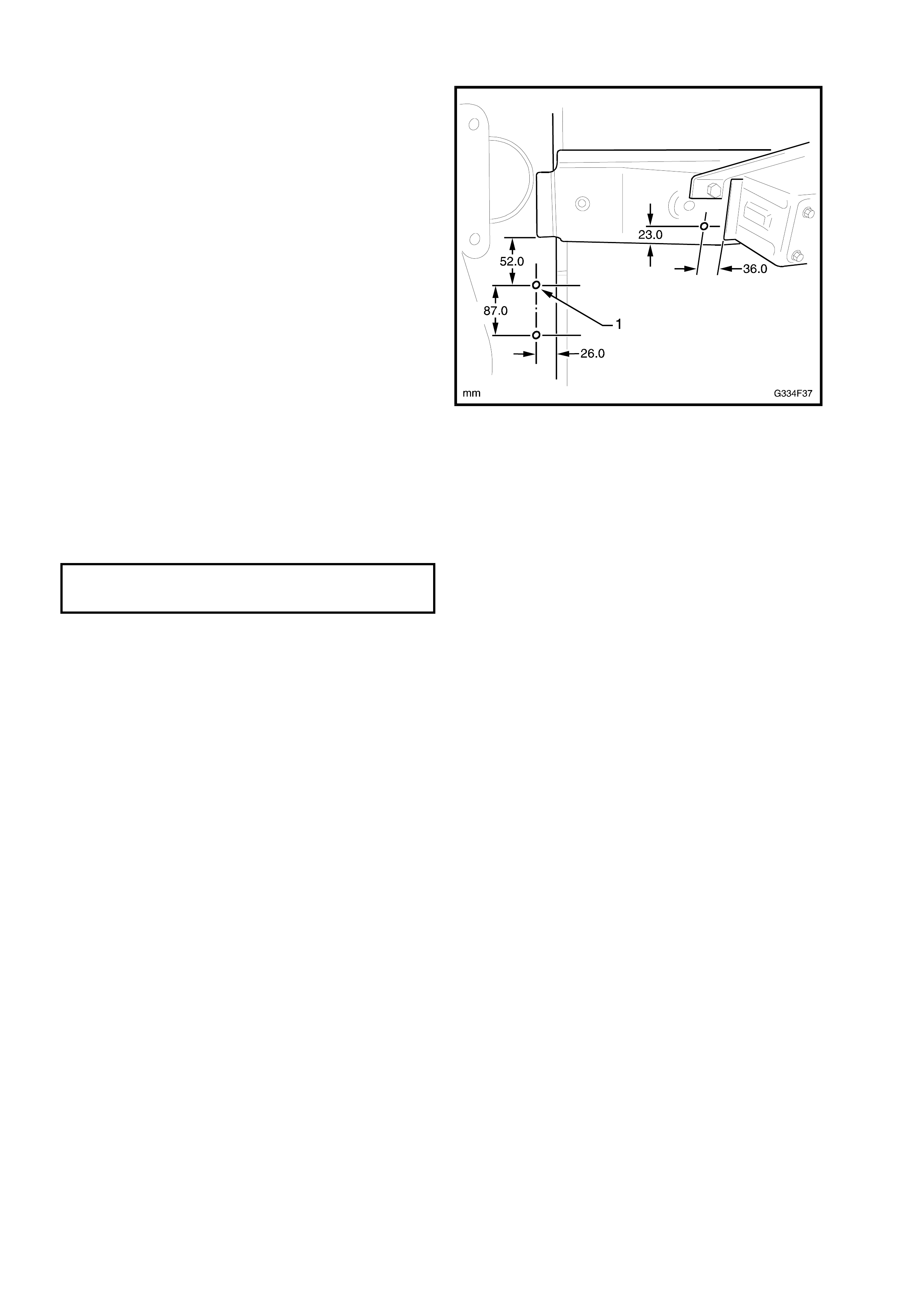
REINST ALL
1. If the LH rear longitudinal and/or crossmember
has been replaced, compressor assembly
mounting holes (1) will have to be drilled as
required.
Figure 4A-12
2. Bring the compressor assembly up to the air line
and connect the T-piece.
NOTE: Ensure the airline is correctly ro uted, placed in
all of its mounting clips and does not foul with, or rub
against any components or body fittings.
3. Install the three mounting bolts and tighten to the
specified torque.
COMPRESSOR ASSEMBLY
MOUNTING BOLTS 4-5 Nm
TORQUE SPECIFICATION
4. Conn ect the wiring har ness connector and clip th e
harness into position.
NOTE: Ensure t he harnes s is correc tly routed, placed
in all of its mounting clips/ties and does not foul with,
or rub against any components or body fittings.
5. Connect the battery.
NOTE: Do not completely lower the vehicle until
system air pressure has been reinstated.
6. Charge the system with air and check the system
for leaks, as described in 4.1 INITIAL AIR
CHARGE and 4.2 AIR LEAK TEST, in this
Section.
4.5 AIR LINES
The air l ines are rou ted between the compres sor and each shock absorber. R etaining clips are place d along eac h
line to secure the air line to the vehicle. Either scre w- on type or clip-on t ype connectors are used to at tach the air
line to the shock absorbers, and a clip-on T-piece attaches the air line to the compressor.
Figure 4A-13
REMOVE
1. De-pressurise the system. Refer 4.3 RELIEVING
SYST EM AIR PRESSURE, in this Section.
SCREW-ON TYPE
2a. Carefully unscrew the connector from the
component and remove air line.
CLIP-ON TYPE
2b. Rotate the connection 90 degrees, then carefully
pull the connector and air line away from the
component.
REINST ALL
1. Route the airline i n the retainers ens urin g ther e
are no k ink s and it does n o t f oul on t he b ody or
any components.
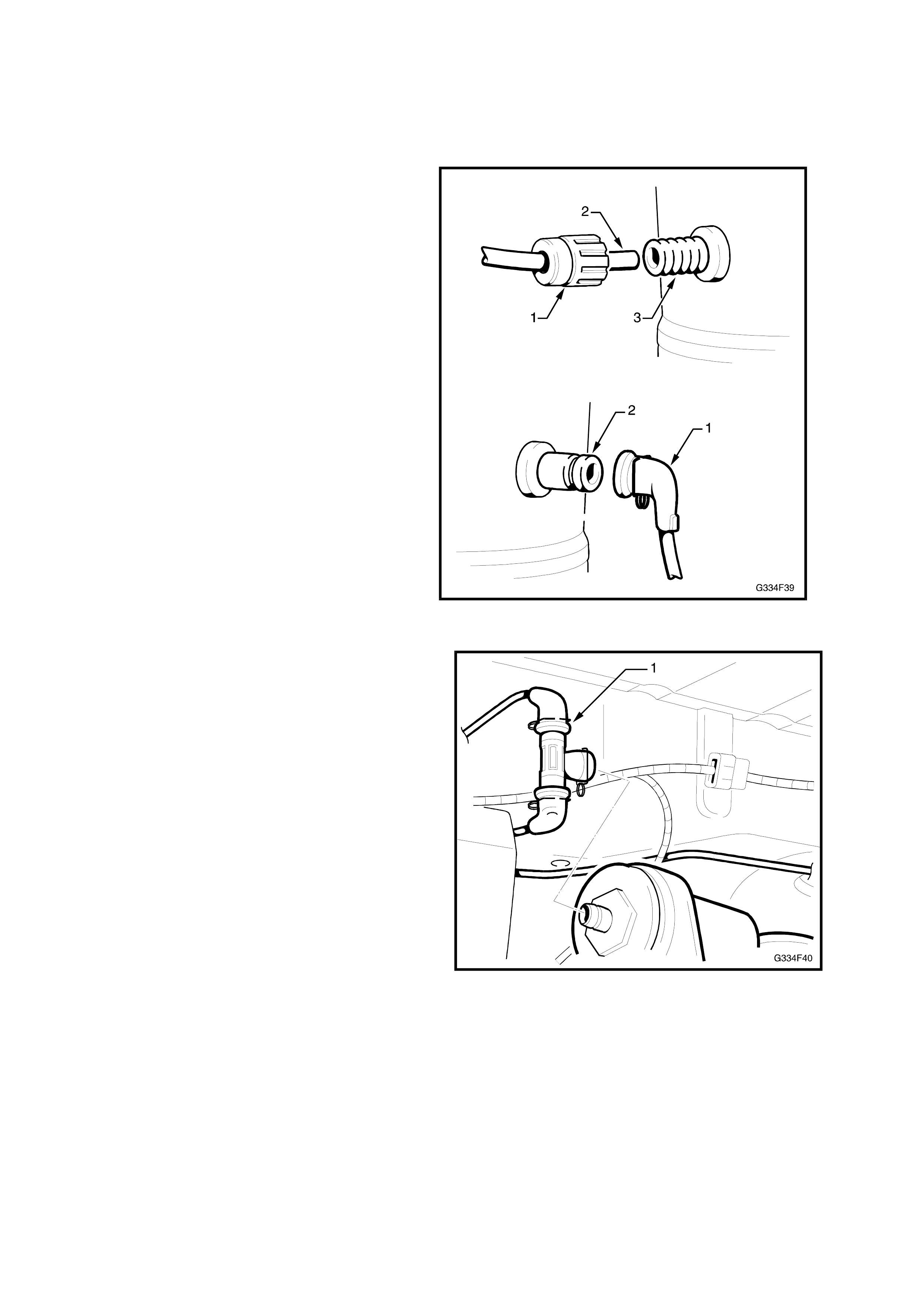
Shock Absorber Screw-on Connection.
2. Fit the connection cap (1) onto the air line (2).
3. Insert the air line into the shock absorber port
(3).
4. Slide the cap along the air line and screw it
onto the shock absorber fitting.
NOTE: Do not over tighten.
Shock Ab sorber Clip-on Connection.
1. Push the connection cap (1) onto the shock
absorber port (2) until the spring clip engages
the groove in the shock absorber fitting.
2. Charge the system with air and test for air
leaks as detailed in 4.1 INITIAL AIR CHARGE
and 4.2 AIR LEA K TEST, in this Section.
Figure 4A-14
Compressor Connection
1. Fit each air line connection onto the T-piece (1).
2. Push the T-piece onto the compressor fitting,
ensuring it is secure.
Figure 4A-15
4.6 SHOCK ABSORBER
REMOVE
1. Raise the rear of the vehicle by placing a jack
under the c entre of th e d if fer enti al c ar rier, raise
the vehicle and place safety stands under the
trailing arms to support the weight of the
vehicle.
2. De-pressurise the system. Refer
4.3 RELIEVING SYSTEM AIR PRESSURE, in
this Section.
3. Disconnect the air line connection from the
shock absorber. Refer 4.5 AIR LINES, in this
Section.
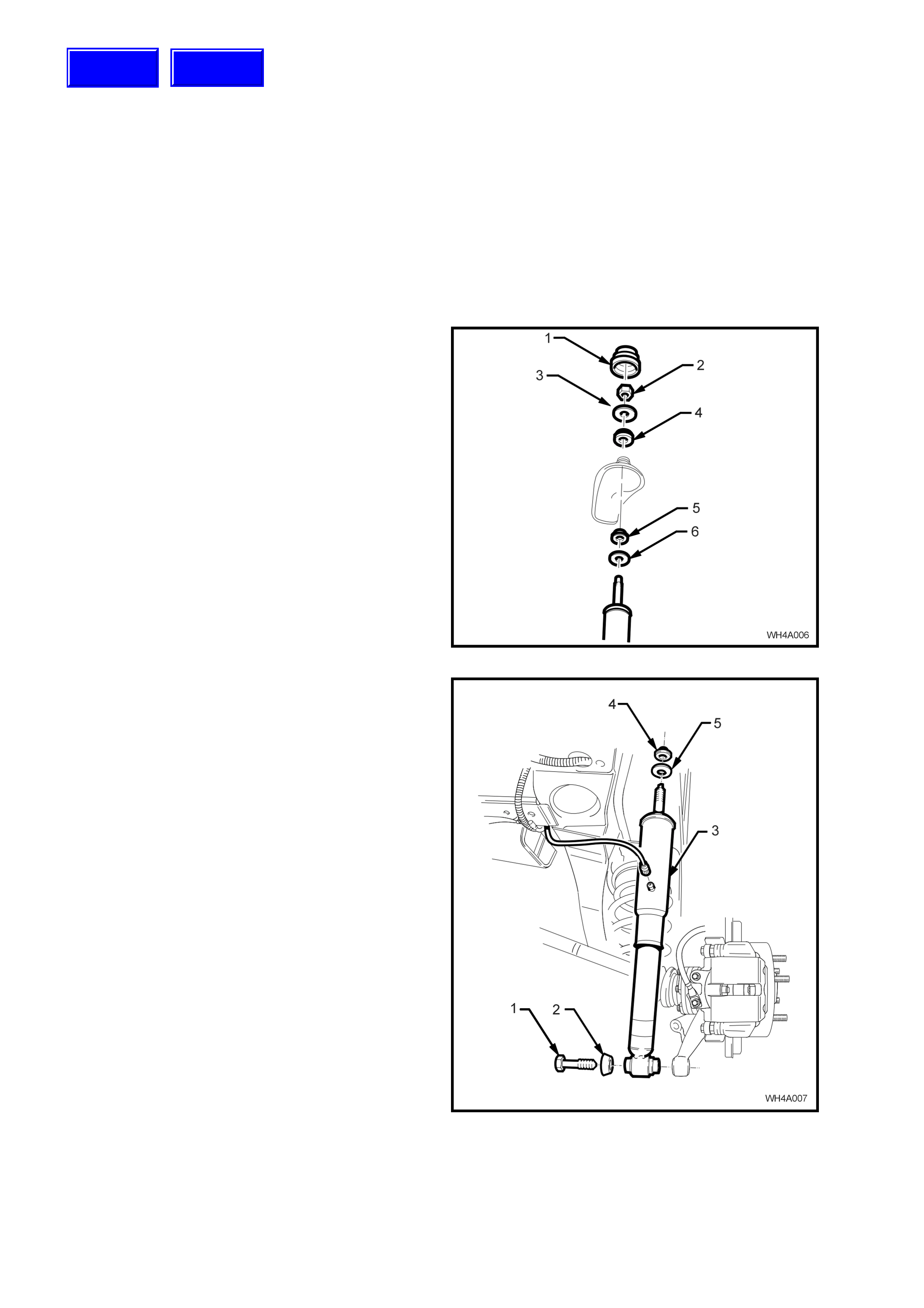
4. Open the rear compartment lid and prise off
the shock absorber upper mounting cap cover
(1).
5. Remove the shock absorber upper mounting
nut (2), upper plate (3) and bush (4).
Figure 4A-16
6. Loosen, the remove the lower shock absorber
mounting bolt (1) and washer (2) from the
lower mounting.
7. Lower the shock absorber (3) to clear the
upper mounting stud from the body, then
remove the shock absorber assembly from the
vehicle.
8. Remove the upper mounting, lower bush (4)
and washer (5) from the shock absorber, as
required.
Figure 4A-17
Techline
Techline

REINST ALL
1. Reinstallation is the reverse to removal
procedures except for the following:
2. With the upper mounting, lower bush (4) and
washer (5) installed, position the shock
absorber upper mounting stud into the body
aperture.
3. Install the upper mounting upper bush, upper
plate and mounting nut.
4. Hand tighten the upper mounting nut until fully
installed onto the threaded section of the shaft.
NOTE: Do not use power operated tools for this
operation, as thread damage will result.
5. Install the upper mounting cap cover.
6. Instal l the shock absorber lo wer mount into th e
trailing arm and install bolt but do not fully
tighten at this stage.
NOTE: Ensure that the air line fitting on the shock
absorber is facing the rear of the vehicle.
7. Reinstall the air line to the shock absorber.
Refer 4.5 AIR L INES, in this Sectio n.
8. Before lowering the vehicle to the ground,
charge the system with air and test for air
leaks as detailed i n 4.1 INITI AL AI R CHARGE
and 4.2 AIR LEAK TEST, in this Section.
9. Lower the vehicle to the ground, then bounce
the vehicle several times to settle the
suspension.
10. Tighten the shock absorber lower mounting
bolt to the correct torque specification.
SHOCK ABSORBER LOWER
MOUNTING BOLT 105 – 125 Nm
TORQUE SPECIFICATION
4.7 RIDE HEIGHT SENSOR
NOTE: The position of the ride height sensor is
critical to the level ride system’s operation. A bent
or damaged mounting bracket, connecting link or
ball stud plate, or incorrect installation of the
sensor and components can be cause of incorrect
operation.
REMOVE
1. Disconnect the battery, negati ve lea d firs t.
2. Unc lip or c ut the cable t ies s ecuring th e sensor
wiring harness to the sensor bracket.
3. Disconnect the wiring harness connector (1)
from the sensor (2).
4. Disconnect the sensor link (3) from either the
sensor arm or ball stud plate (4).
5. While holdi ng t he s ens or a s s em bl y, rem ove th e
bolt (5) attaching the sensor mounting bracket
(6) to the crossmember.
6. Remove the sensor assembly.
7. If required, remove the nuts (7) attaching the
sensor to the mounting bracket.
8. If required, remove the bolt (8) attaching the
ball stud plate to the trailing arm.
Figure 4A-18
REINST ALL
1. Reinstallation of the ride height sensor is the
reverse to removal procedures except for the
following:
SENSOR BRACKET TO
CROSSMEMBER BOLT 15-30 Nm
TORQUE SPECIFICATION
SENSOR TO B RACKET NUTS
TORQUE SPECIFICATION 3-8 Nm
STABILISER BAR LINK BOLT & N U T
TORQUE SPECIFICATION 95-105 Nm
NOTE: If the rear suspension crossmember has
been replaced, insert the nut cage (1) into the
crossmember as shown.
Figure 4A-19
5. DIAGNOSIS & WIRING
The following procedures are designed to assist in the diagnos is of a fault in the level ride s ystem. To achieve an
accurate diagnosis, the Technician must be familiar with the principles of operation of the system, before
proceeding.
The diagnosis tables contained in this Section are to be used in conjunction with the wiring schematic and wiring
harness diagrams, also provided.
EQUIPMENT
A digita l multim eter with a m inimum 10 Meg ohm im pedance m ust be us ed when undertak ing any el ectrical check s
with this s ystem .
When performing tests on the wiring harness, use the appropriate probe adaptor to ensure the wiring and/or
connectors are not damaged during testing.
RIDE HEIGHT SENSOR RESET
If the compressor or exhaust solenoid operate for more than four and a half minutes, the sensor timers must be
reset by turning the ignition on, then off for one minute, then on again.
5.1 PRELIMINARY DIAGNOSTIC P ROCE DURE
STEP ACTION VALUE YES NO
1. Does the vehicle trim ? Go to Step 2. Go to Step 3.
2. Does the vehicle trim to the correct height? Refer to 6.
SPECIFICATIONS
in this Section.
System OK. Check all
suspension
components for
wear & damage,
paying particular
attention to the
ride height sensor
mounting &
bracket.
3. Does the vehicle rise after the specified time
when the vehicle is loaded?
Place load in the vehicle.
20 seconds. Go to Step 4. Go to 5.2,
Compressor
Assembly Test-
Motor.
4. Does the vehicle lower after the specified time
when the vehicle is unl oade d.
Remove load from the vehicle.
20 seconds System OK. Go to 5.3,
Compressor
Assembly Test-
Solenoid.
Techline

5.2 COMPRESSOR ASSEMBLY TEST - MOTOR
STEP ACTION VALUE YES NO
1. Has a system reset been performed? Go to Step 2. Perform system
reset. Refer the
beginning of this
Section.
2. Is fuse FJ OK?
(Located in the engine compartment fuse & relay
panel assembly).
Go to Step 3. Replace blown
fuse. Check wiring
for the cause of
the blown fuse.
Re-check sy stem.
3. Are fuses F24 & F15 OK?
(Located in the passenger compartment fuse &
relay panel assembly).
Go to Step 4. Replace blown
fuse(s). Check
wiring for the
cause of the blown
fuse(s). Re-check
system.
4. 1. Disconnect the wiring harness at the ride
height sensor.
2. Turn the ignition on.
3. Bridge Pin 3 & Pin 4 in the ride height
sensor connect or.
Listen for the compressor motor running, or
Check for voltage between Pins B & D at
the compress or harness connector.
Is the compressor motor running and the voltage
as specified?
• Motor running,
or
• 12 Vol ts at the
compressor
harness
connector Pins
B & D.
Compressor motor
OK. Proceed to
5.4, Height Sensor
Test - C ompressor
Go to Step 5.
5. Check the wiring harness for continuity.
Is the wir ing harness c onti nuity OK? Continuity. Replace the
compressor
assembly. Refer
4.4 in this Section.
Repair or replace
harness.

5.3 COMPRESSOR ASSEMBLY TEST - SOLENOID
STEP ACTION VALUE YES NO
1. Has a system reset been performed? Go to Step 2. Perform system
reset. Refer the
beginning of this
Section.
2. Is fuse FQ OK?
(Located in the engine compartment fuse & relay
panel assembly).
Go to Step 3. Replace blown
fuse. Check wiring
for the cause of
the blown fuse.
Re-check sy stem.
3. Are fuses F6 & F15 OK?
(Located in the passenger compartment fuse &
relay panel assembly).
Go to Step 4. Replace blown
fuse/s. Check
wiring for the
cause of the blown
fuse/s. Re-check
system
4. 1. Disconnect the wiring harness at the level
ride sensor.
2. Turn the ignition on.
3. Bridge Pin 2 & Pin 4 in the ride height
sensor connect or.
Listen for a clicking of the solenoid valve &
air escaping from the system, or;
Check for voltage between Pins A & C at
the compress or harness connector.
Are all conditions present and voltage as
specified?
• Clicking sound
from the
solenoid & air
escaping or,
• 12 Vol ts at the
compressor
harness
connector Pins
A & C.
Compressor
assembly solenoid
OK. Proceed to
5.5, Height Sensor
Test - Solenoid.
Go to Step 5.
5. Check the wiring harness for continuity.
Is the wir ing harness c onti nuity OK? Continuity Replace the
compressor
assembly. Refer
4.4 in this Section.
Repair or replace
the harness.

5.4 RIDE HEIGHT SENSOR TEST - COMPRESSOR
STEP ACTION VALUE YES NO
1. Has a system reset been performed? Go to Step 2. Perform system
reset. Refer the
beginning of this
Section.
2. 1. Disconnect the ride height sensor
connecting link. Refer Section 4.7 in this
Section.
2. Turn the ignition on.
3. Raise the ride height sensor arm 45
degrees & wait 20 seconds.
4. Listen for the compressor motor running, or
Check for voltage between Pins B & D at
the compress or harness connector.
Does the compressor run or is the voltage as
specified?
• Compressor
motor running,
or
• 12 volts at pins
B & D.
Go to Step 3. Go to Step 6.
3. The compressor motor may be operating but the
compressor may have failed.
Run the motor for two minutes & check the
shock absorber air bag s are being pres sur ised.
Is air pressure present in the shock absorber air
bags?
−
System OK.
Recheck sy stem
for correct
operation if
necessary.
Go to Step 4.
4. Check the air compressor filter for blockage.
Is the filter blocked? Filter OK. Go to Step 5. Replace filter &
recheck the
system.
5. Check the air lines for correct fitment, kinks &
damage.
Are all air lines OK?
−
Replace the
compressor
assembly &
recheck the
system.
Replace air line &
recheck the
system.
6. Check wiring harness for continuity.
Is the wir ing harness c onti nuity OK? Continuity. Replace the ride
height sensor
assembly. Refer
4.7 in this Section.
Repair or replace
harness.
5.5 RIDE HEIGHT SENSOR TEST - SOLENOID
STEP ACTION VALUE YES NO
1. Has a system reset been performed? Go to Step 2. Perform system
reset. Refer the
beginning of this
Section.
2. 1. Disconnect the ride height sensor
connecting link. Refer 4.7 in this Section.
2. Turn the ignition on.
3. Lower the ride height sensor arm 45
degrees & wait 20 seconds.
4. Listen for clicking of the solenoid valve & air
escaping from the system, or
Check for voltage between Pins A & C at
the compress or harness connector.
Are all conditions present and voltage as
specified?
• Clicking sound
from the
solenoid & air
escaping, or
• 12 volts at pins
A & C.
System OK.
Recheck sy stem
for correct
operation if
necessary.
Go to Step 3.
3 Check the wiring harness for continuity.
Is the wir ing harness c onti nuity OK? Continuity. Replace the ride
height sensor
assembly. Refer
4.7 in this Section.
Repair or replace
harness.
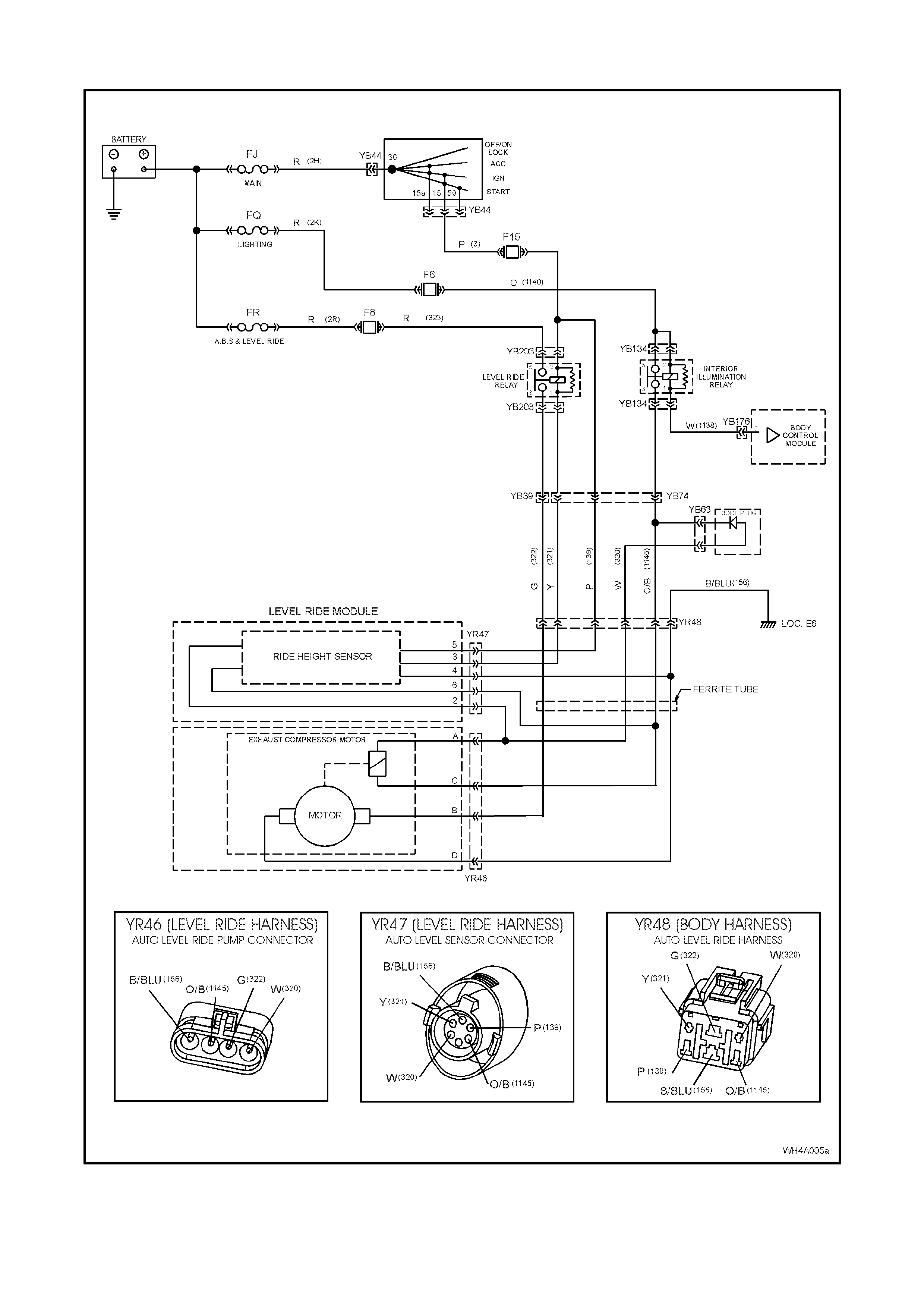
5.6 LEVEL RIDE SUSPENSION WIRING DIAGRAM
Figure 4A-20
5.7 LEVEL RIDE SUSPENSION WIRING HARNESS LAYOUT
1. Level Ride Wiring Harness 2. Ride Height Sensor Wiring Harness 3. Compressor Wiring Harness
Figure 4A-21
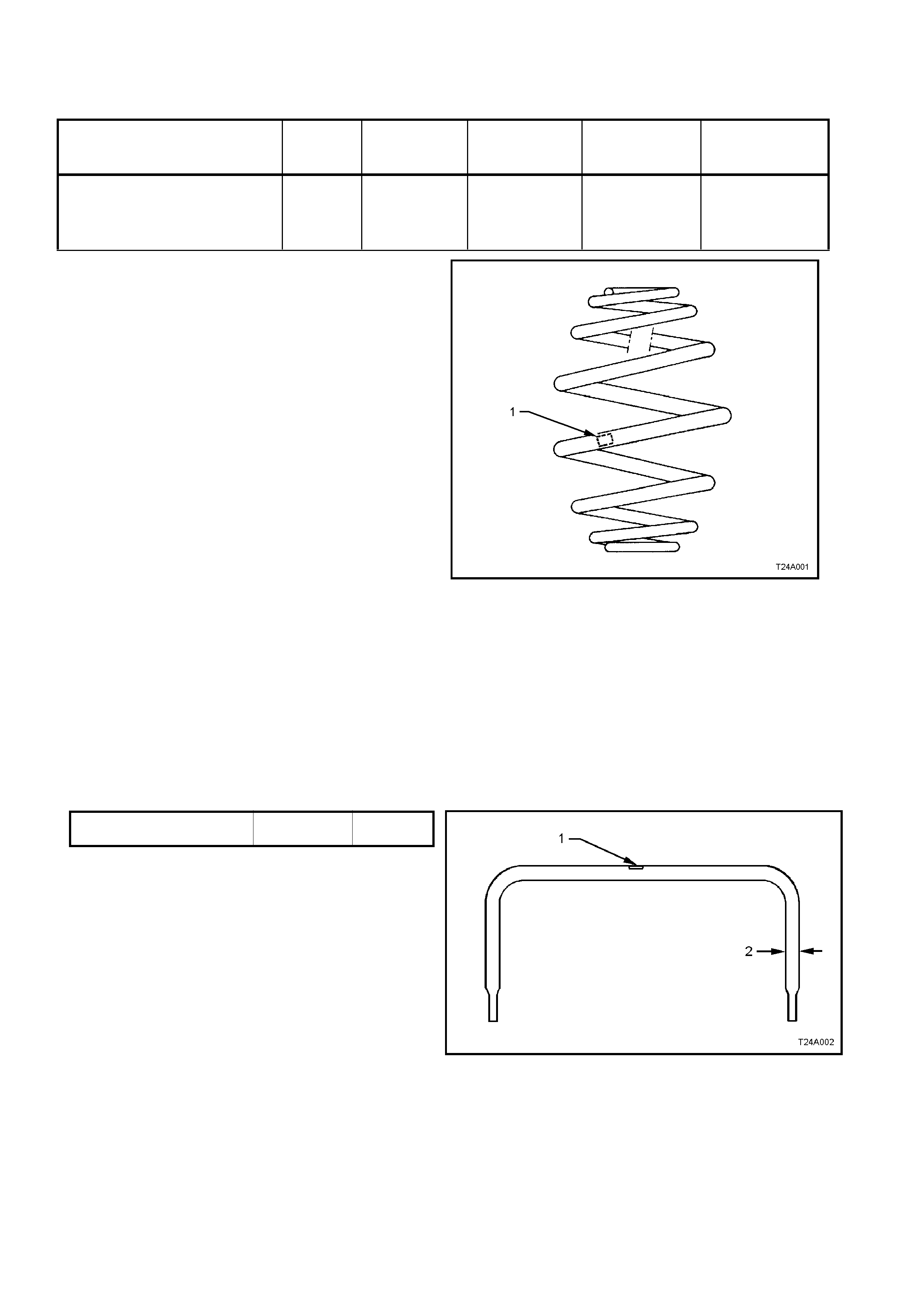
6. SPECIFICATIONS
REAR SPRING DET AILS
MODEL TOTAL
No.
COILS
FREE
LENGTH mm OUTSIDE
DIAM. mm PROD. I.D.
CODE
(Tag on spring)
SPRING TYPE &
RATE
STATESMAN – V6 ENGINE -
STANDARD SUSPENSION
CAPRICE – GEN III V8 ENGINE
STANDARD SUSPENSION
7.8 284
+ 0
158
- 20 EV
VARIABLE
40.0/71.0 N/mm
(5200 ± 180 N @
156 mm)
LEGEND
1. Production Identification Code Tag
Figure 4A-22
REAR SHOCK ABSORBER DETAILS
Type
Superlift..................................................................... Twin tube hydraulic, gas pressurised
Production Identification Code................................ ME
STABILISER BAR DETAILS
Type ........................................................................ Linkless
MODEL Dim. “A” in PROD.
Fig 4A-22 I.D. CODE
Statesman and Caprice Models
with Standard Suspension 16.0 mm FK
Figure 4A-23
Legend
1. Production Identification Code Tag
2. Bar Diameter
SUSPENSION AND TRIM HEIGHT SPECIFICATIONS
Refer to 3. FRONT SUSPENSION, of the WH Service Information.

7. TORQUE SPECIFICATIONS Nm
Compressor to Mounting Bracket Bolt.................................. 4 – 5
Compressor Mounting Bracket to Body Securing Screw ..... 4 – 5
Ride Height Sensor to Mounting Bracket Nut....................... 3 – 8
Ride Height Sensor Bracket to Crossmember Bolt .............. 15 – 30
Stabiliser Bar Link Bolt and Nut............................................ 95 – 105
Shock Absorber Lo wer Mo unti ng Bo lt .................................. 105 – 125
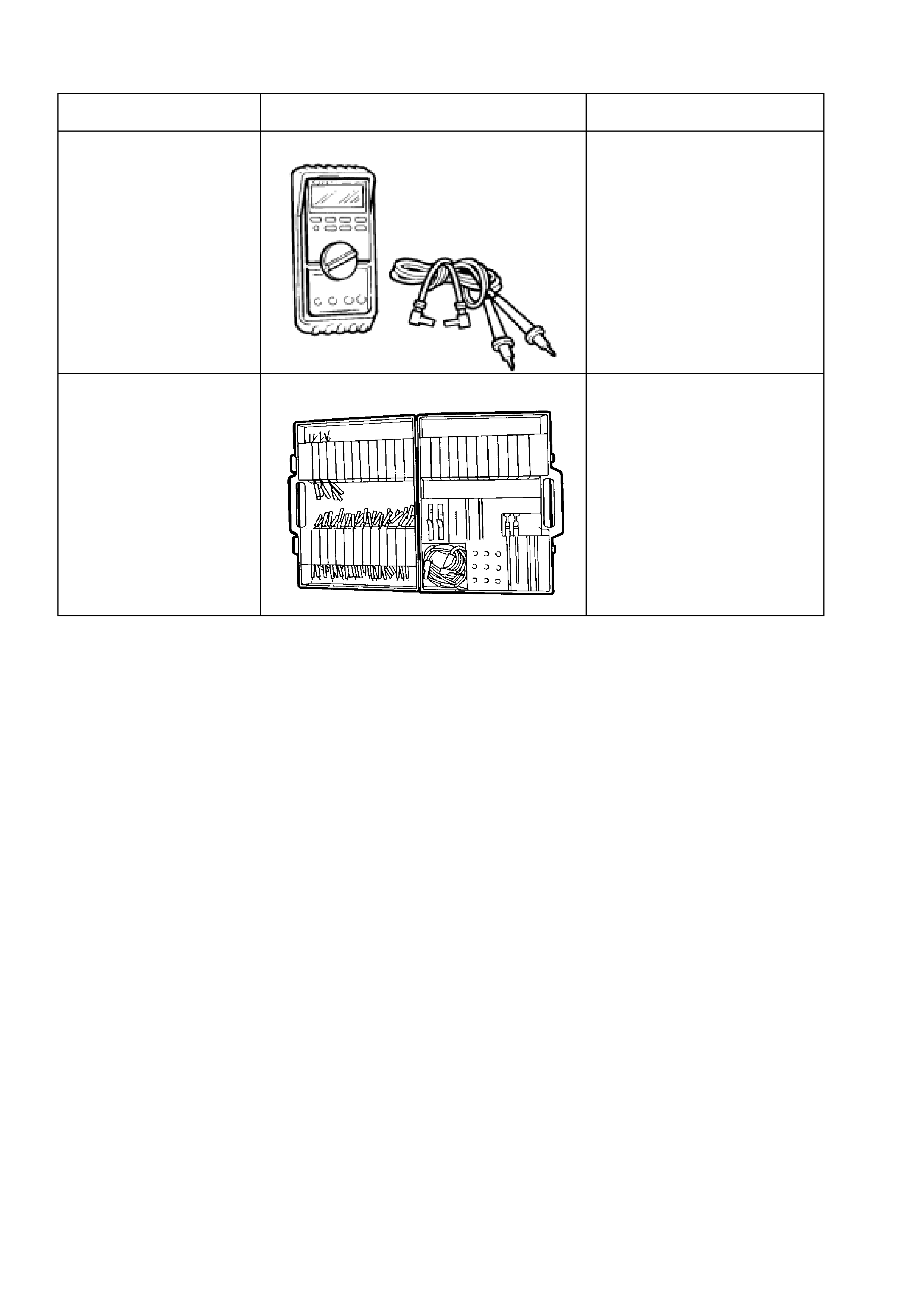
8. SPECIAL TOOLS
TOOL No. REF. IN TEXT TOOL DESCRIPTION COMMENTS
J 39200 DIGITAL MULTIMETER Previously released.
Also commercially available, but
must have a 10 Megohm input
impedance
KM-609 ELECTRONIC KIT
Previously released.
Used in conjunction with a
multimeter for measuring
voltages and resistances
without damaging wiring
harnesses connectors