WIRING DIAGRAMS
VU12P0A
2.1 HOW TO USE THE SYSTEM WIRING
DIAGRAMS
The vehicle's complete electrical wiring is divided into
separate system wiring diagrams, i.e. Starting and
Charging, Fusible Links, Central Door Locking etc.
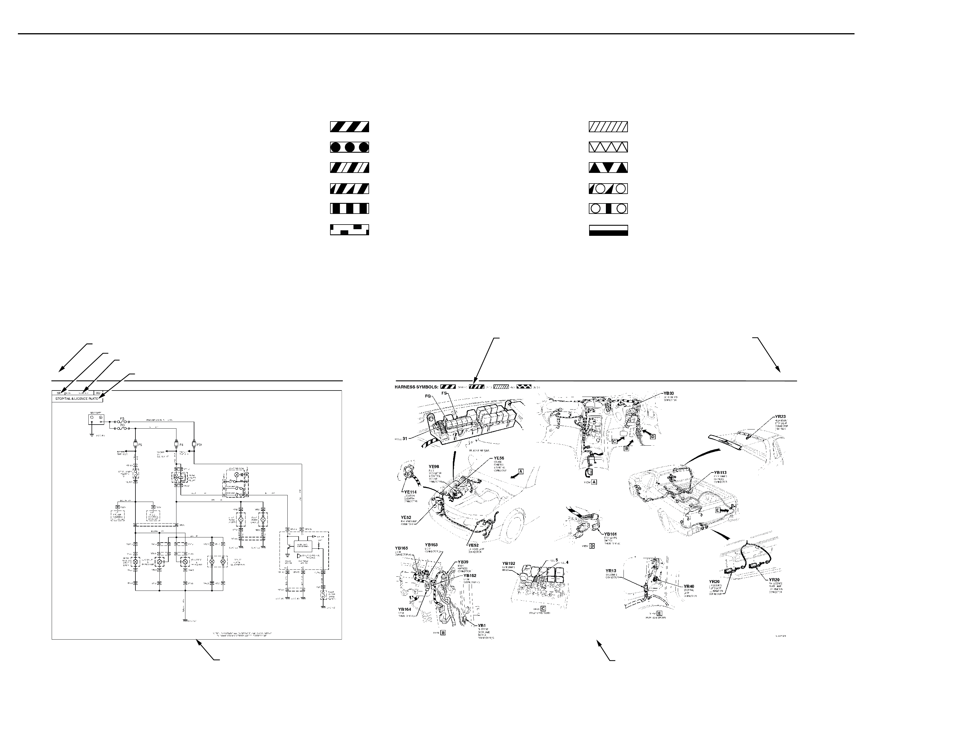
The following figure is an example of a typical system wiring
diagram.
The system wiring diagram is shown on both left and right
hand pages. When reading the system wiring diagrams, the
following points should be noted:
1. Where possible, all wiring diagrams show the complete
circuit from battery '+' terminal, through the system to
earth.
2. Refer to next page for detailed explanation of the single
line system wiring diagrams.
KNOCK SENSOR HARNESS (K.S.)
ENGINE COOLING FAN HARNESS (E.C.)
HARNESS SYMBOLS LEGEND
BATTERY HARNESS (BAT.)
POWER TRAIN HARNESS (P.T.) LIQUID PETROLEUM GAS (L.P.G.)
FRONT DOOR HARNESS (F.D.)
BODY HARNESS (B.)
ENGINE HARNESS (E.)
MAIN WIRING HARNESS (M.W.H.)
ROOF LAMP HARNESS (R.L.)
POWER SEAT (P.S.)
PAGE NUMBER
HARNESS SYMBOLS LEGEND
SYMBOLS FOR APPLICABLE
SYSTEM HARNESSES ARE SHOWN
RIGHT HAND PAGE
ILLUSTRATES VARIOUS VIEWS OF APPLICABLE
MODELS AND SPECIFIC VIEWS, SHOWING
HARNESS ROUTING, HARNESS IDENTIFICATION,
CONNECTOR BODY LOCATION AND IDENTIFICATION.
12P-XX
WIRING DIAGRAMS
12P-XX
PAGE NUMBER
SYSTEM REFERENCE NUMBER
SYSTEM WIRING DIAGRAM
APPLICATION
SYSTEM WIRING DIAGRAM WIRING DIAGRAMS
LEFT HAND PAGE
SINGLE LINE SYSTEM
WIRING DIAGRAM
LIGHTS ON HARNESS (L.O.)