
TECH 2 Page 0C–1
Page 0C–1
Section 0C
TECH 2
ATTENTION
Before performing any Service Operation or other procedure described in this Section, refer to Section 00
WARNINGS, CAUTIONS AND NOTES for correct workshop practices with regard to safety and/or property
damage.
1 General Information............................................................................................................................... 2
1.1 Using TECH 2 On The Vehicle...............................................................................................................................2
Connecting the TECH 2 to the Vehicle.................................................................................................................2
1.2 Application Menus .................................................................................................................................................6
Body Control Module.............................................................................................................................................6
Security...............................................................................................................................................................6
Multi Function Display...........................................................................................................................................6
Normal Mode......................................................................................................................................................7
Diagnostic Trouble Codes ..................................................................................................................................7
Data Display.......................................................................................................................................................7
Data List .............................................................................................................................................................7
System Identification...........................................................................................................................................8
Snapshot ............................................................................................................................................................8
Miscellaneous Tests...........................................................................................................................................8
Program..............................................................................................................................................................8
Premium Sound Amplifier .....................................................................................................................................9
Diagnostic Trouble Codes ................................................................................................................................10
Data Display.....................................................................................................................................................10
Snapshot ..........................................................................................................................................................10
Miscellaneous Tests.........................................................................................................................................10
Program............................................................................................................................................................11
Audio Interface Module........................................................................................................................................12
Diagnostic Trouble Codes ................................................................................................................................13
Data Display.....................................................................................................................................................13
Snapshot ..........................................................................................................................................................13
Miscellaneous Tests.........................................................................................................................................13
Security.............................................................................................................................................................13
DVD Player............................................................................................................................................................14
Diagnostic Trouble Codes ................................................................................................................................15
Data Display.....................................................................................................................................................15
Program............................................................................................................................................................15
Security.............................................................................................................................................................15
Seat and Exterior Mirror Memory Module ..........................................................................................................16
Diagnostic Trouble Codes ................................................................................................................................17
Data Display.....................................................................................................................................................17
Snapshot ..........................................................................................................................................................17
Miscellaneous Tests.........................................................................................................................................17
Additional Functions .........................................................................................................................................18
Techline
Techline
Techline
Techline
Techline
Techline
Techline
TECH 2 Page 0C–2
Page 0C–2
1 General Information
With the following exceptions, MY 2004 WK Series TECH 2 information carries over from MY 2003 VY Series vehicles.
For information not contained within this Section, refer to Section 0C TECH 2 in the MY 2003 VY and V2 Series Service
Information.
• Body Control Module (BCM)
• Multi Function Display (MFD).
• Premium Sound Amplifier (PSA)
• Audio Interface Module (AIM).
• DVD Player.
• Seat and Exterior Rear View Mirror.
1.1 Using TECH 2 On The Vehicle
Connecting the TECH 2 to the Vehicle
The following TECH 2 screen displays may very with different applications and versions of TECH 2 software.
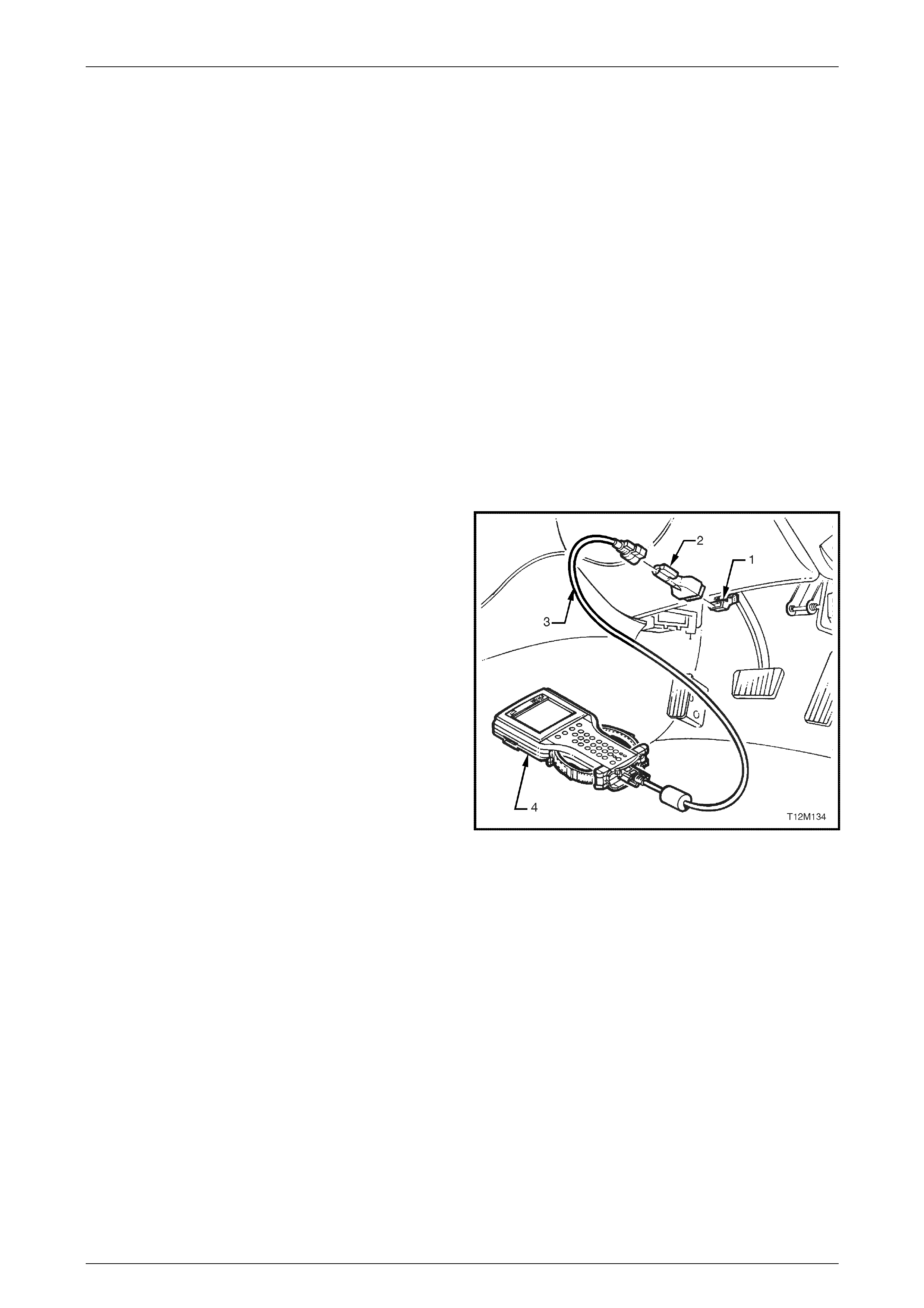
1 Connect TECH 2 (4) to the vehicle DLC (1), with the
DLC cable (3) and the 16/19 pin adapter (2).
Figure 0C-1 Connecting the TECH 2 to the Vehicle
TECH 2 Page 0C–3
Page 0C–3
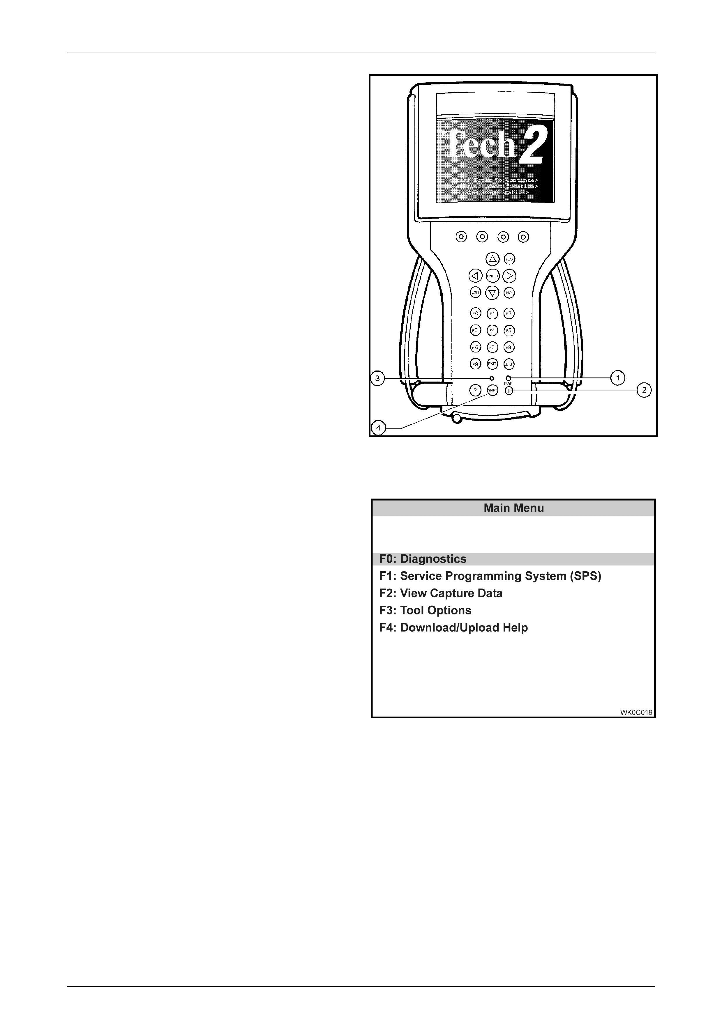
2 Switch the unit on by pressing the power button
(2). A green light (1) should come on indicating that
the tool is receiving power.
At this time the technician should see the Power
On Self Test (POST) run. The POST is a built in
diagnostic self test for the TECH 2 that should find
most common system faults. The POST is run on
every power up to ensure the best operation of the
tool. After the completion of the POST, the TECH 2
unit will briefly show the POST results. If POST
passes, the tool will continue onto the title screen.
If POST fails, results of all tests will be displayed,
and this should show which test failed. POST
failures may be classified as fatal or non-fatal. A
fatal error will not allow the user to continue using
the tool. Failure of the keypad would be an
example of a fatal error. Non-fatal errors found
during the POST will allow continued use of the
TECH 2, but with some limitations. If either a fatal
or non-fatal error occurs, refer to the
Troubleshooting section of the TECH 2 User's
Guide.
Legend:
1 Power Status I ndicator Li ght
2 PWR (Power) Key
3 SHIFT Key Status Indicator Light
4 SHIFT Key
3 At the TECH 2 title screen press the ENTER key to
continue.
Figure 0C-2 TECH 2 PWR and SHIFT Keys
4 A selection can be made from the Main M enu,
either by using a function key or by using the arrow
keys to highlight a menu choice and pressing
ENTER.
NOTE: You will then need to supply some
additional information to the TECH 2. This requires
navigation through a series of lists (called picklists).
On some menus or picklists, the user can use a
function key to make a menu selection, but most of
the picklists require using the selection and action
keys. If a mistake is made in the selection process,
or if a different application or function is desired,
press EXIT to back up one level. Within an
application, there may be soft keys which are
available for use. These soft keys allow access to
additional tool functions without exiting a current
tool function. Soft keys are made up of sets which
will appear together. To see the next set of soft
keys, select the More soft key.
Figure 0C-3 TECH 2 Main Menu
5. The TECH 2 Main Menu contains the following:
F0: Diagnostics
Contains all functions to test, diagnose, monitor and program the different vehicle systems.
F1: Service Programming System (SPS)
SPS is used in conjunction with Technical Information System (TIS) 2000 to program vehicle control units.
F2: View Capture Data
Contains all functions to work with one or two previously recorded snapshots on one or two vehicles. This function
is to enable the viewing of captured data without a vehicle.
F3: Tool Options
Contains the TECH 2 self test, set clock, set units, set screen contrast and CANdi Diagnostics.
F4: Download/Upload Help
Contains help information on the downloading and uploading from the TECH 2 to the TIS 2000.
TECH 2 Page 0C–4
Page 0C–4
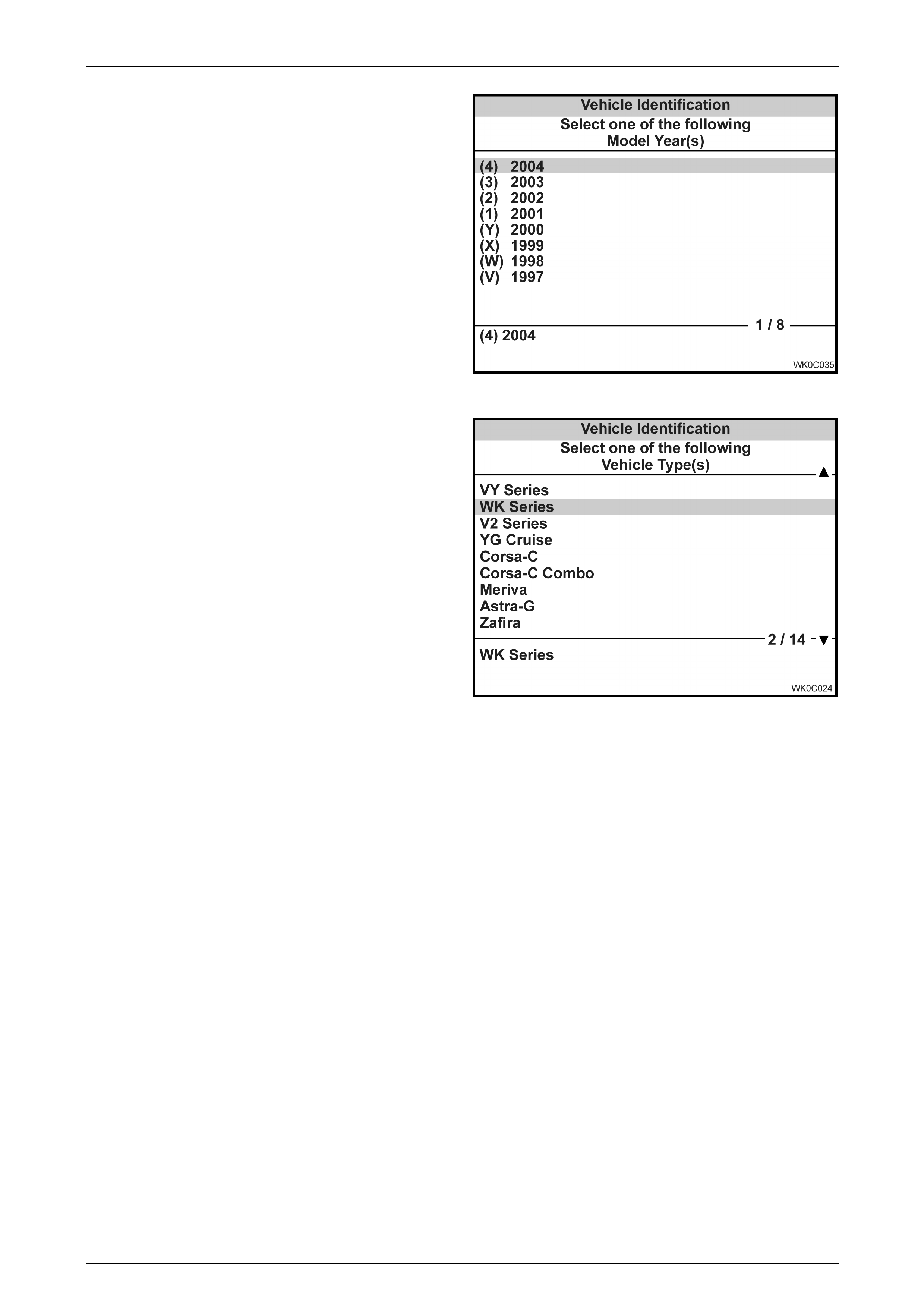
1 Select the correct Model Year, 2003 or 2004 with
the arrow keys and the press ENTER. The Main
Menu Vehicle Identification screen will then be
displayed.
Figure 0C-4 TECH 2 Vehicle Identification Menu
2 Select the correct Vehicle Type, WK Series with the
arrow keys and the press ENTER. The System
Select Menu will then be displayed.
Figure 0C-5 TECH 2 Vehicle Identification
TECH 2 Page 0C–5
Page 0C–5
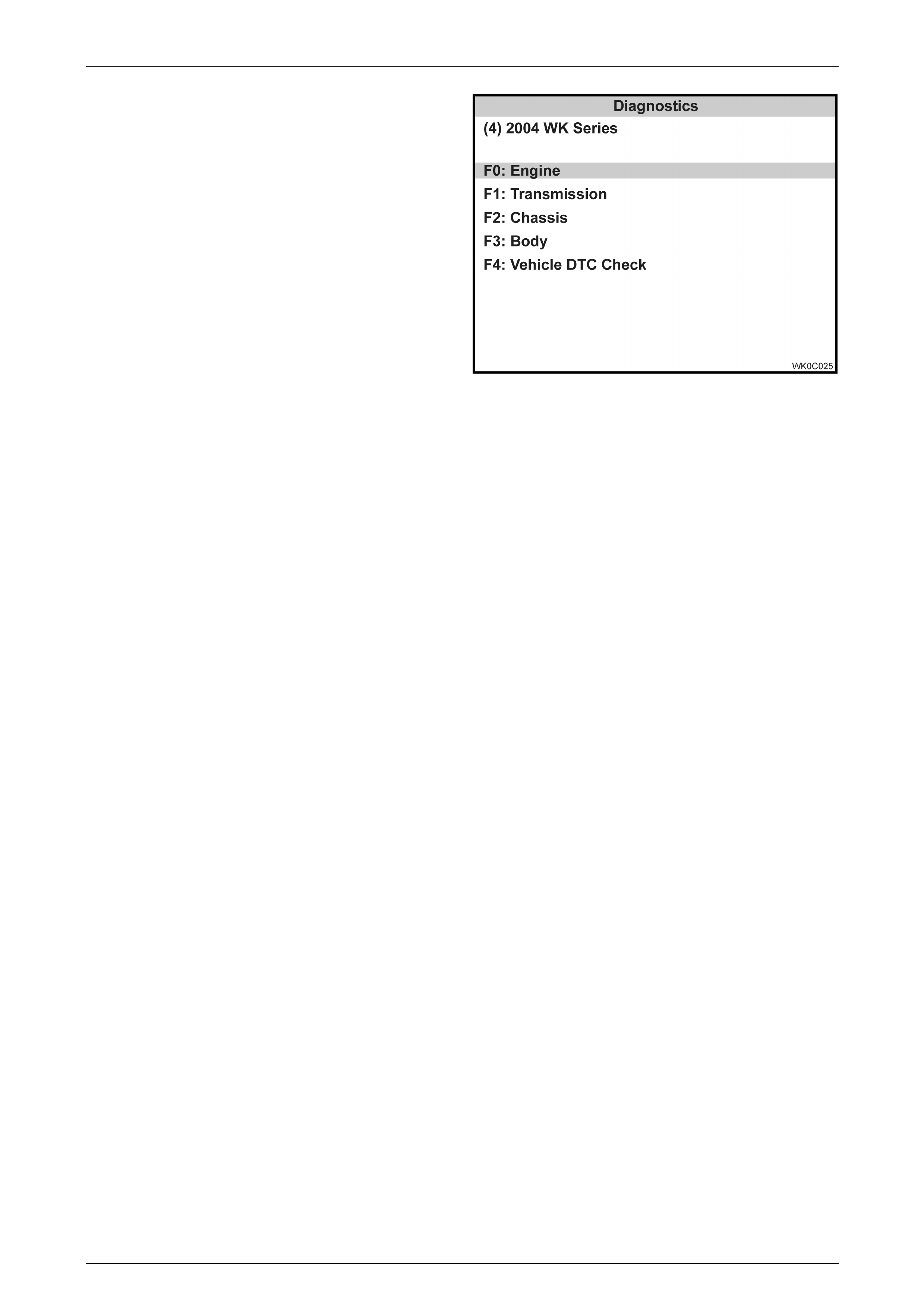
3. The desired system can be selected from the
System Select Menu with the function keys or with
arrow keys and then press ENTER.
F0: Engine
Contains all functions to test, diagnose, and
monitor the engine systems that communicate with
the TECH 2 via the Powertrain Control Module
(PCM).
F1: Transmission
Contains all functions to test, diagnose, monitor
and program the transmission systems that
communicate with the TECH 2 via the Powertrain
Control Module (PCM).
F2: Chassis
Contains all functions to test, diagnose, monitor
and program the vehicles chassis systems; ABS
and Electronic Traction Control modules.
F3: Body
Contains all functions to test, diagnose, monitor
and program the vehicles body systems; Body
Control Module, Powertrain Interface Module,
Supplemental Restraint System, Instruments, Multi
Function Display, Occupant Climate Control,
Telematics Module, Audio System, Premium
Sound Amplifier, Audio Interface Module, DVD
player and Seat and Exterior Mirror Memory
Module.
F4: Vehicle DTC Check
This function allows yo u to check all modu les on
the UART serial data circuit for Diagnostic Trouble
Codes (DTC). There is also a function to clear all
DTCs.
Note: This function does not display or clear V8
GEN III PCM DTCs.
Figure 0C-6 TECH 2 System Select Menu
TECH 2 Page 0C–6
Page 0C–6
1.2 Application Menus
Body Control Module
With the introduction of the DVD player and the Audio Interface Module in the WK Series an additional Tech 2 function
has been added to the WK Series TECH 2 software. To access this security function, select the following from the WK
Series Body Application menu: Body Control Module/Security/AIM Link to BCM once selected follow the screen
instructions to perform the linking function.
Security
AIM Link to BCM
This linking function allows the technician to to link the Audio Interface Module (AIM) to the BCM. This function must be
performed if the AIM or the BCM, has been replaced. If the AIM is not linked to the BCM the DVD Player will not operate.
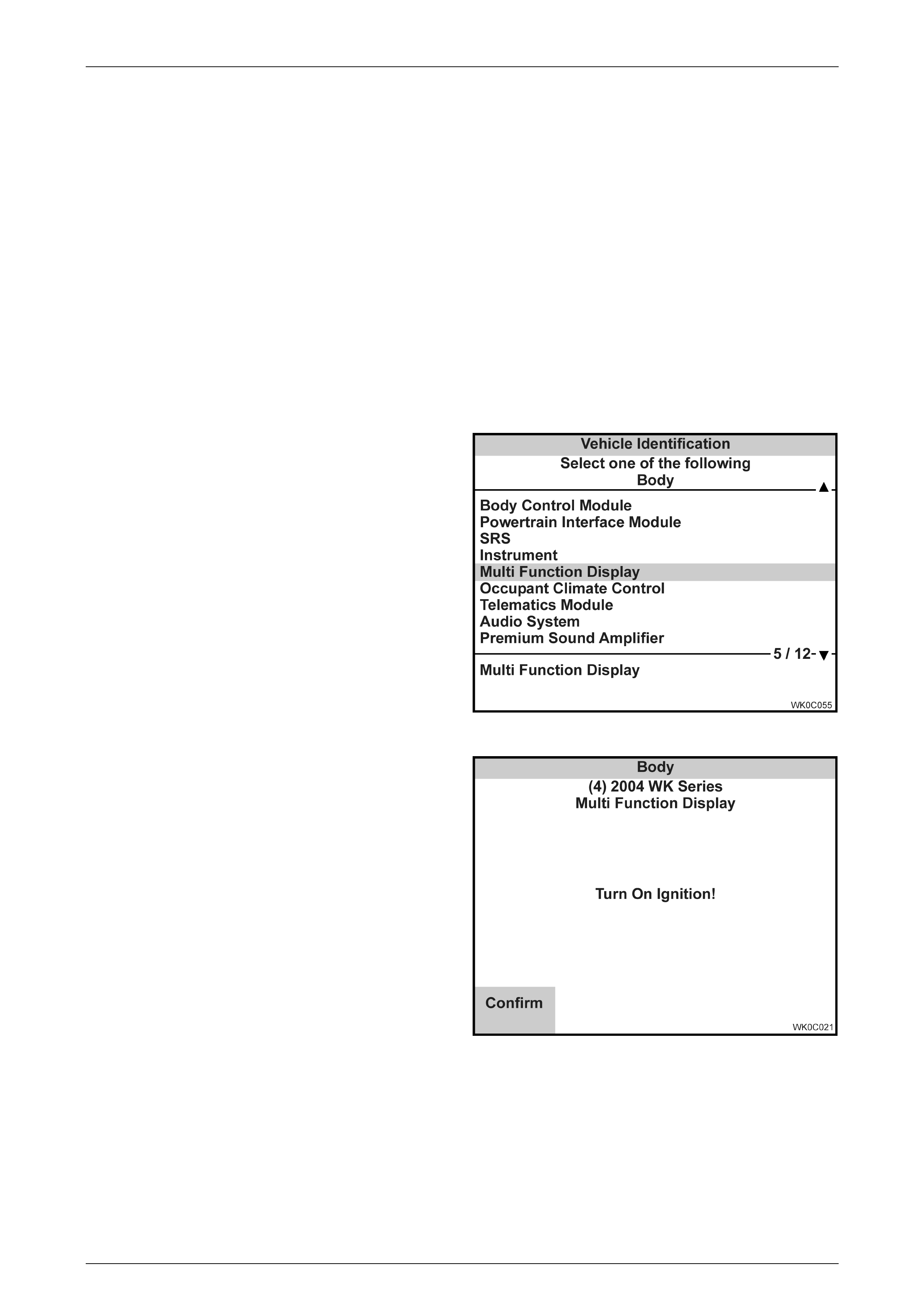
Multi Functi on Display
1 Select Multi Function Display (MFD) from the
Vehicle Identification menu with the arrow keys, then
press ENTER.
Figure 0C-7 Vehicle Identification Menu
2 Turn on the ignition and press the Confirm soft
key.
The System Identification screen will then display
the following information:
Figure 0C-8 System Identification
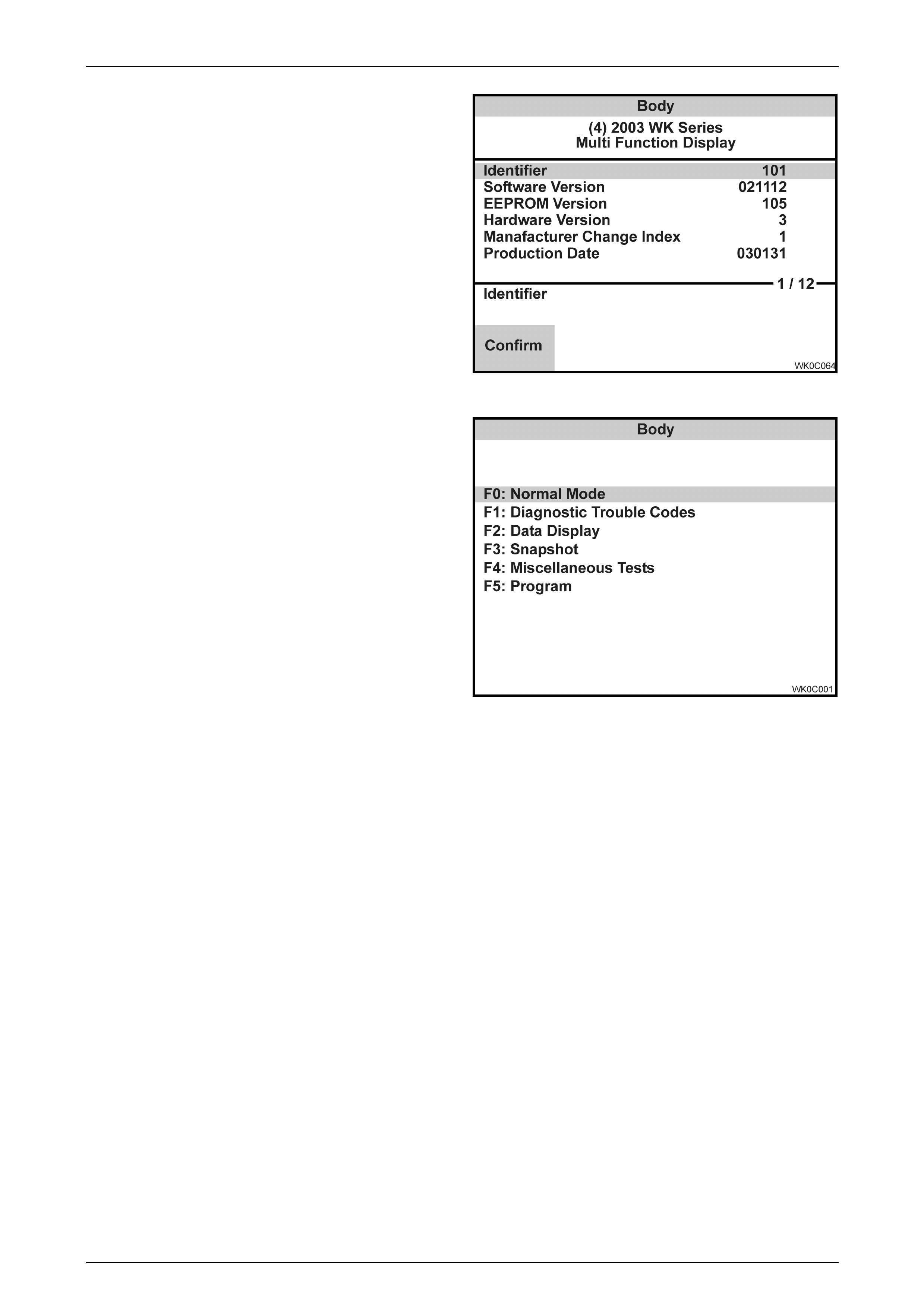
TECH 2 Page 0C–7
Page 0C–7
Identifier
Software Version
EEPROM Version
Hardware Version
Manufacture Change Index
Production Date
Partnumber
TAG Number
Code Index
Code Version
12/24 Hour Clock
VAP Process Number
3 Press the Confirm soft key the Multi Function
Display application menu will then be displayed.
Figure 0C-9 System Identification
The following Multi Function Display functions are
available:
F0: Normal Mode
F1: Diagnostic Trouble Codes
F2: Data Display
F3: Snapshot
F4: Miscellaneous Tests
F5: Program
NOTE: Functions may vary depending on the
application selected. For further Multi Function
Display information refer to Section 12I Multi
Function Display.
Figure 0C-10 MFD Application Menu
Normal Mode
In this test mode, TECH 2 will display various Multi Function Display data parameters that are being transmitted to the
audio system AHU via the Multi Function Display serial data circuit.
Diagnostic Trouble Codes
In this test mode, DTCs stored by the Multi Function Display can be displayed or cleared. When F1: Diagnostic Trouble
Codes is select ed there is an additional two modes :
F0: Read DTC Information
If this mode is selected, a listing of all (if any) DTCs that have been set will be displayed. Information displayed with the
DTC number/s that have been set is; a short description of the DTC, and if the DTC is current or history.
F1: Clear DTC Information
Once F1: Clear DTC Information has been selected, DTCs can be cleared by simply pressing the Yes soft key.
Data Display
When entering this mode the following data lists are available:
Data List
In this test mode, TECH 2 displays the status of inputs and outputs of the Multi Function Display.

TECH 2 Page 0C–8
Page 0C–8
System Identification
In this test mode, the TECH 2 displays the Multi Function Display identification information. This data list is the same as
the information displayed on the system identification screen.
Snapshot
In this test mode, TECH 2 captures the data list data before and after a selected trigger point. The purpose of the
snapshot test mode is to help isolate an intermittent or transient problem by storing instrument data parameters just
before and just after a problem occurs.
Miscellaneous Tests
Miscellaneous Tests allows for the testing of the Multi Function Display to assist in problem isolation during trouble
shooting. When this mode is selected, the following options will become available. To exit any miscellaneous test press
the Quit soft key or the EXIT key.
Park Lamp Switch
Precondition: Turn Park Lamps ON.
This miscellaneous test allows you to simulate the park lamp switch input. This is achieved by using the Up and
Down soft keys.
All Segments
Precondition: None.
In this miscellaneous test all the segments in the audio display can be turned Off and On using the Off and On soft
keys.
Chequered Pattern
Precondition: None.
In this miscellaneous test the segments in the audio display can be turned Off and On in a chequered pattern using
the Off, On and Inverse soft keys.
Program
Program Code Index
This programming mode allows the technician to program the MFD clock to 12 Hour or 24 Hour. The current code index
and code version and the MFD clock mode, 12 or 24 hour are displayed, as well as providing the operator the option to
modifying the code index. If the Modify soft key is pressed the operator can then select 12 Hour Clock or 24 Hour Clock.
TECH 2 Page 0C–9
Page 0C–9
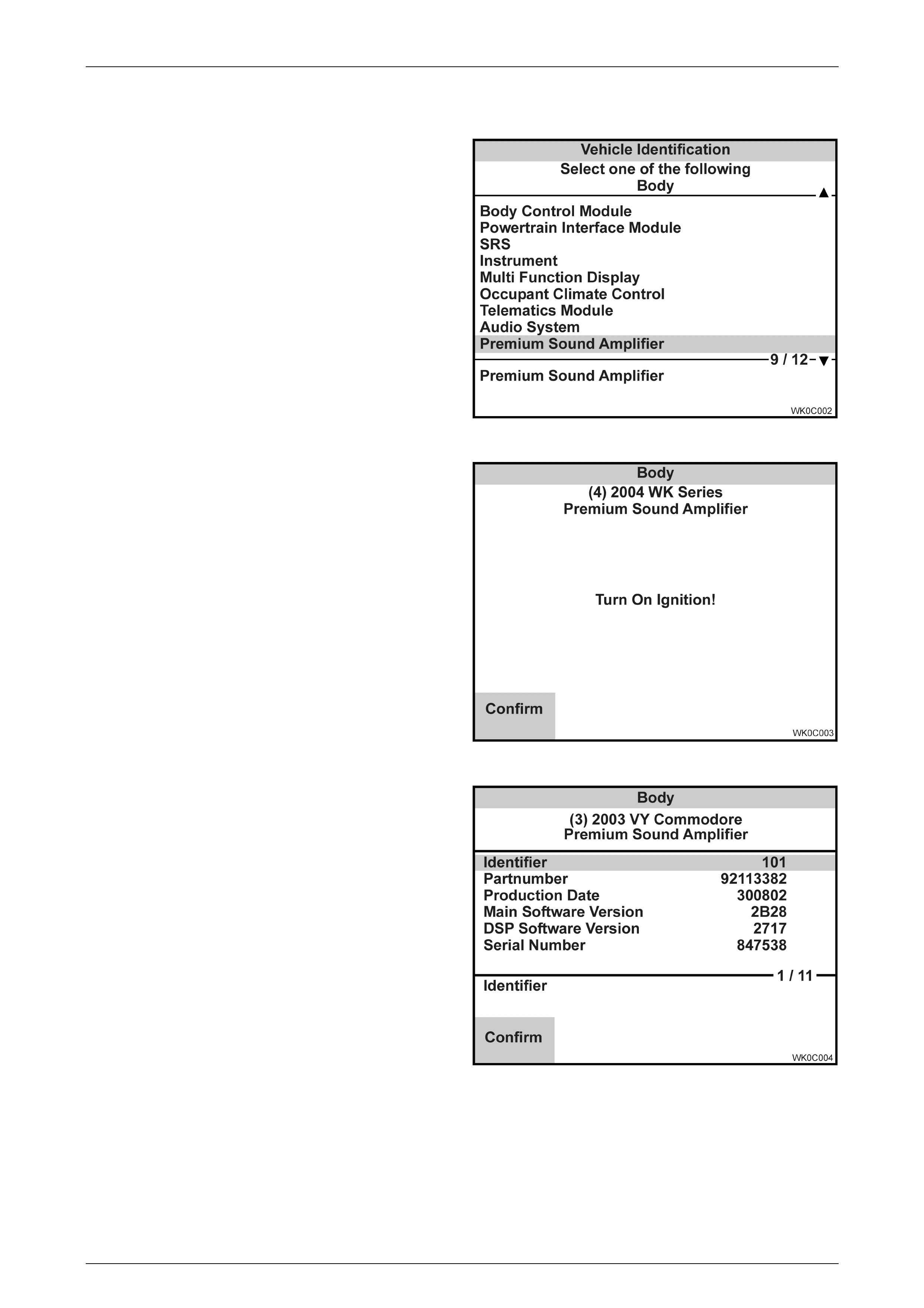
Premium Sound Amplifier
1 Select Premium Sound Amplifier (PSA) from the
Vehicle Identification menu with the arrow keys,
then press ENTER.
Figure 0C-11 Vehicle Identification Menu
2 Turn on the ignition and press the Confirm soft
key.
The System Identification screen will then display
the following information:
Figure 0C-12 System Identification
Identifier
Partnumber
Production Date
Main Software Version
DSP Software Version
Serial Number
VAP Process Number
Code Index
Code Version
VIN Digit 1-10
VIN Digit 11-17
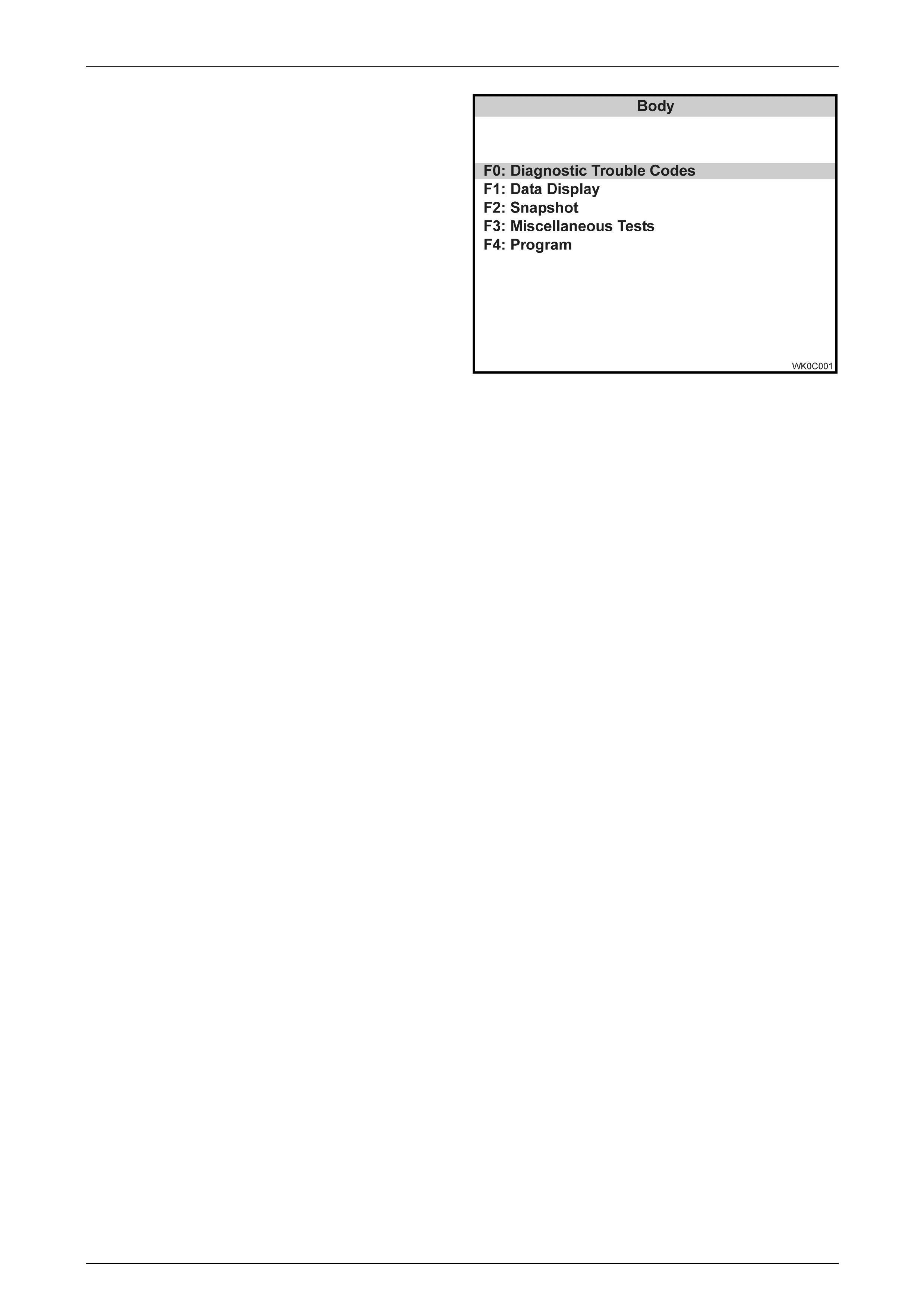
3 Press the Confirm soft key, the Premium Sound
Amplifier application menu will then be displayed.
Figure 0C-13 System Identification
TECH 2 Page 0C–10
Page 0C–10
The following Premium Sound Amplifier functions
are available:
F0: Diagnostic Trouble Codes
F1: Data Display
F2: Snapshot
F3: Miscellaneous Tests
F4: Program
NOTE: Functions may vary depending on the
application selected. For further Premium Sound
Amplifier information refer to Section 12D
Entertainment System.
Figure 0C-14 PSA Application Menu
Diagnostic Trouble Codes
In this test mode, DTCs stored by the Premium Sound Amplifier can be displayed or cleared. When F1: Diagnostic
Trouble Codes is selected there is an additional two modes:
F0: Read DTC Information
If this mode is selected, a listing of all (if any) DTCs that have been set will be displayed. Information displayed with the
DTC number/s that have been set is; a short description of the DTC, if the DTC is current (fault present) or history
(stored, but not necessarily present on this ignition cycle), the number of times the DTC has Occurred and the Ignition
Cycles since the DTC was last set.
F1: Clear DTC Information
Once F1: Clear DTC Information has been selected DTCs can be cleared by simply pressing the Yes soft key.
Data Display
When entering this mode the following data lists are available:
Data List
In this test mode, TECH 2 displays the status of inputs and outputs of the Premium Sound Amplifier.
System Identification
In this test mode, the TECH 2 displays the Premium Sound Amplifier identification information. This data list is the same
as the information displayed on the system identification screen.
Snapshot
In this test mode, TECH 2 captures the data list data before and after a selected trigger point. The purpose of the
snapshot test mode is to help isolate an intermittent or transient problem by storing instrument data parameters just
before and just after a problem occurs.
Miscellaneous Tests
Miscellaneous Tests allows for the testing of the PSA to assist in problem isolation during trouble shooting. When this
mode is selected, the following options will become available. To exit any miscellaneous test press the Quit soft key or
the EXIT key.
PSA (On / Off)
This miscellaneous test allows the user to command the PSA on and off using the On and Off Soft keys.
Mute
This miscellaneous test allows you to mute the PSA using the Mute and Unmute soft keys.

TECH 2 Page 0C–11
Page 0C–11
Gain
This miscellaneous test allows the gain for each channel to be controlled by using the Decrease and Increase soft keys.
The Next Channel soft key is used to switch between the following channels: Front Speaker and Tweeter, Rear and Roof
Speaker and Sub-Woofer.
Speaker
This miscellaneous test allows the active speaker channel to be changed by the user from the Tech 2. During this test
the PSA generates a test tone which is sent to the selected speaker channel, the test tone can be commanded on and
off using the On and Off soft keys. The Next Speaker soft key is used to switch between the following speaker channels:
Loudspeaker Front right, Loudspeaker Front Left, Loudspeaker Rear Right, Loudspeaker Rear Left, Sub-Woofer Right
and Sub-Woofer Left.
Program
Program Code Index
This programming mode allows the technician to program the PSA Code Index. When selected the current code index
and code version are displayed. If the Program soft key is pressed the operator can then enter the desired code index.
TECH 2 Page 0C–12
Page 0C–12
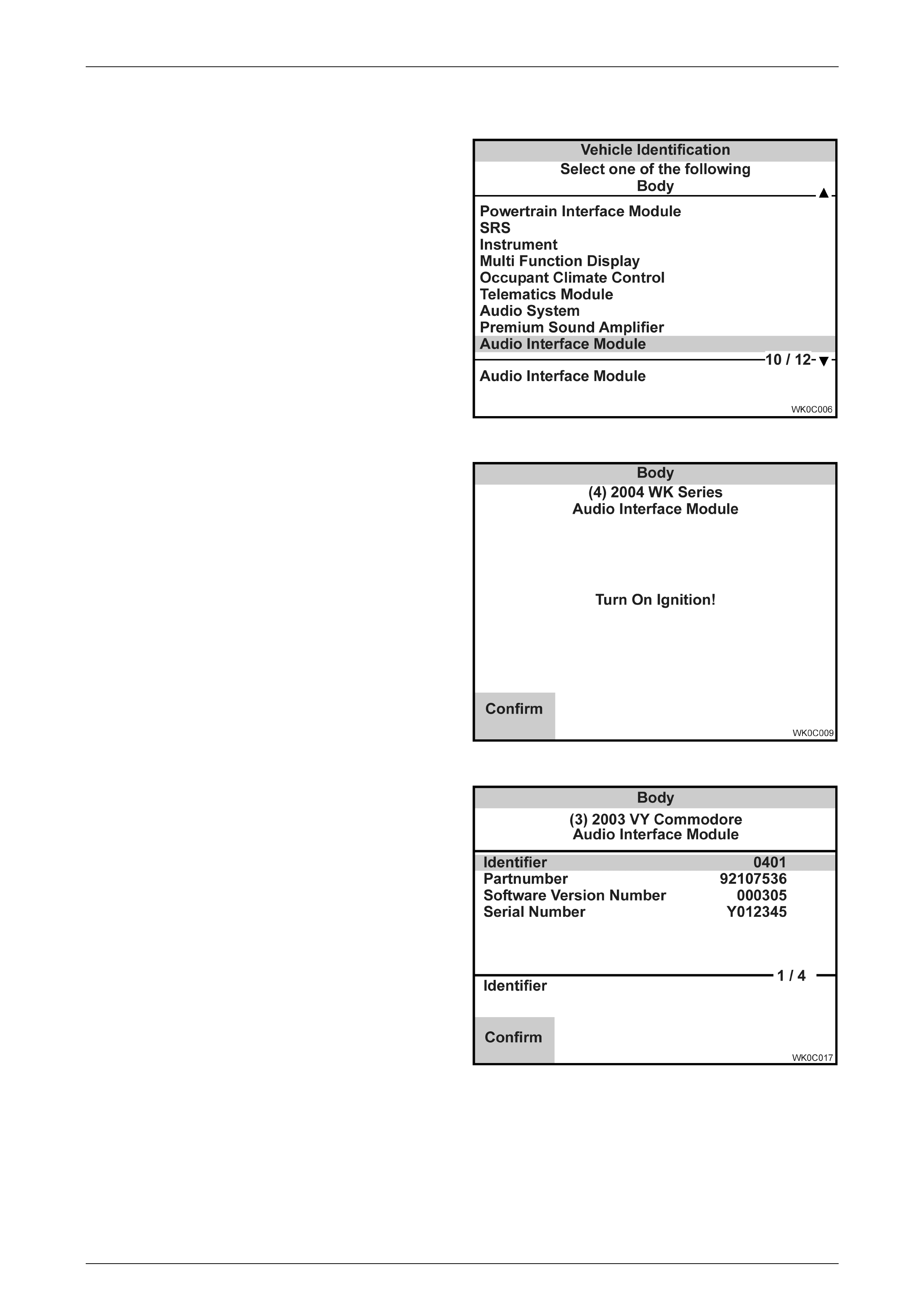
Audi o I nt erface Modul e
1 Select Audio Interface Module (AIM) from the
Vehicle Identification menu with the arrow keys,
then press ENTER.
Figure 0C-15 Vehicle Identification Menu
2 Turn on the ignition and press the Confirm soft
key.
The System Identification screen will then display
the following information:
Figure 0C-16 System Identification
Identifier
Partnumber
Production Date
Software Version Number
Serial Number
3 Press the Confirm soft key, the Audio Interface
Module application menu will then be displayed.
Figure 0C-17 System Identification

TECH 2 Page 0C–13
Page 0C–13
The following Audio Interface Module functions are
available:
F0: Diagnostic Trouble Codes
F1: Data Display
F2: Snapshot
F3: Miscellaneous Tests
F4: Security
NOTE: Functions may vary depending on the
application selected. For further Audio Interface
Module information refer to Section 12D
Entertainment System.
Figure 0C-18 AIM Application Menu
Diagnostic Trouble Codes
In this test mode, DTCs stored by the Audio Interface Module can be displayed or cleared. When F1: Diagnostic Trouble
Codes is select ed there is an additional two modes :
F0: Read DTC Information
If this mode is selected, a listing of all (if any) DTCs that have been set will be displayed. Information displayed with the
DTC number/s that have been set is; a short description of the DTC, if the DTC is current (fault present) or history
(stored, but not necessarily present on this ignition cycle), the number of times the DTC has Occurred and the Ignition
Cycles since the DTC was last set.
F1: Clear DTC Information
Once F1: Clear DTC Information has been selected, DTCs can be cleared by simply pressing the Yes soft key.
Data Display
Data List
In this test mode, TECH 2 displays the status of inputs and outputs of the AIM.
System Identification
In this test mode, the TECH 2 displays the AIM identification information. This data list is the same as the information
displayed on the system identification screen.
Snapshot
In this test mode, TECH 2 captures the data list data before and after a selected trigger point. The purpose of the
snapshot test mode is to help isolate an intermittent or transient problem by storing instrument data parameters just
before and just after a problem occurs.
Miscellaneous Tests
Miscellaneous Tests allows for the testing of the Audio Interface Module to assist in problem isolation during trouble
shooting. When this mode is selected, the following options will become available. To exit any miscellaneous test, press
the Quit soft key or the EXIT key.
DVD Illumination Control
Precondition: None.
This miscellaneous test allows you to control the DVD illumination from the Audio Interface Module. This is achieved by
using the Decrease and Increase soft keys or the Left and Right arrow keys. On exiting this test TECH 2 will request that
the ignition is cycled Off and On.
Security
AIM Link to BCM
This linking function allows the technician to link the AIM to the BCM. This function must be performed if the AIM or the
BCM has been replaced. If the AIM is not linked to the BCM the DVD Player will not operate.
TECH 2 Page 0C–14
Page 0C–14
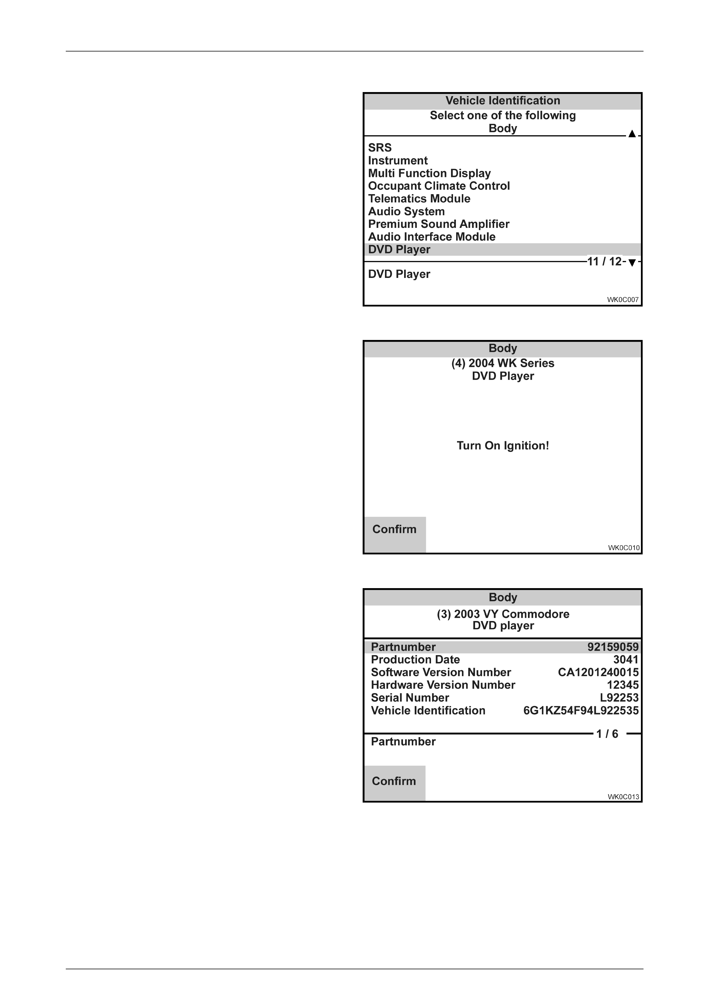
DVD Player
1 Select DVD Player from the Vehicle Identification
menu with the arrow keys, then press ENTER.
Figure 0C-19 Vehicle Identification Menu
2 Turn on the ignition and press the Confirm soft
key.
The System Identification screen will then display
the following information:
Figure 0C-20 System Identification
Partnumber
Production Date
Software Version Number
Hardware Version Number
Serial Number
Vehicle Identification Number
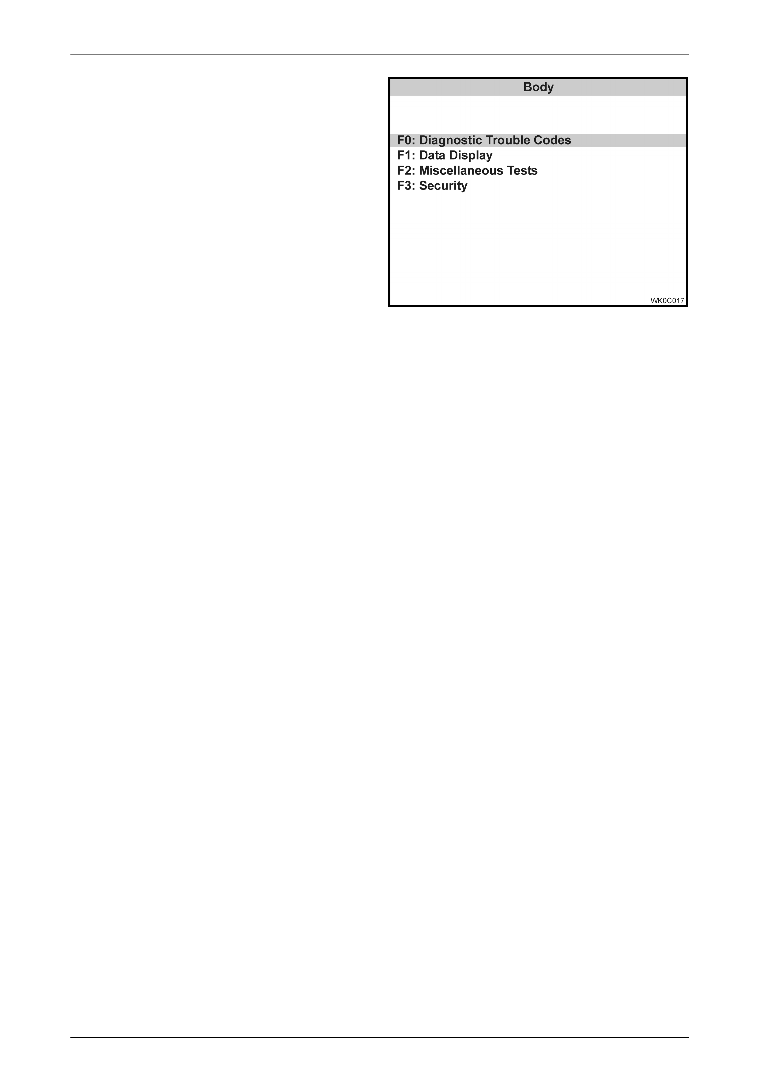
3 Press the Confirm soft key, the DVD Player
application menu will then be displayed.
Figure 0C-21 System Identification
TECH 2 Page 0C–15
Page 0C–15
The following DVD Player functions are available:
F0: Diagnostic Trouble Codes
F1: Data Display
F2: Program
F3: Security
NOTE: Functions may vary depending on the
application selected. For further Audio Interface
Module information refer to Section 12D
Entertainment System.
Figure 0C-22 DVD Player Application Menu
Diagnostic Trouble Codes
In this test mode, DTCs stored by the DVD Player can be displayed or cleared. When F1: Diagnostic Trouble Codes is
selected there is an additional two modes:
F0: Read DTC Information
If this mode is selected, a listing of all (if any) DTCs that have been set will be displayed. Information displayed with the
DTC number/s that have been set is; a short description of the DTC, if the DTC is current (fault present) or history
(stored, but not necessarily present on this ignition cycle).
F1: Clear DTC Information
Once F1: Clear DTC Information has been selected DTCs can be cleared by simply pressing the Yes soft key.
Data Display
When entering this mode the following data list is available:
System Identification
In this test mode, the TECH 2 displays the DVD Player identification information. This data list is the same as the
information displayed on the system identification screen.
Program
F0: Program Region Code
This programming function allows the technician to program the DVD Player region code and video format. New DVD
players will be programmed to region 1 and NTSC video format. Once programming has been selected Tech 2 will
display the current region code and video format, and the region code and video format to be programmed. W hen the
Program soft key is pressed Tech 2 will program the region code and video format. Programming function can only be
performed once if the region code and video format have already be programmed Tech 2 will display “Selected
Programming Not Possible”.
Security
AIM Link to BCM
This linking function allows the technician to technician to link the Audio Interface Module to the BCM. This function must
be performed if the Audio Interface Module or the BCM has been replaced. If the Audio Interface Module is not linked to
the BCM the DVD Player will not operate.
TECH 2 Page 0C–16
Page 0C–16
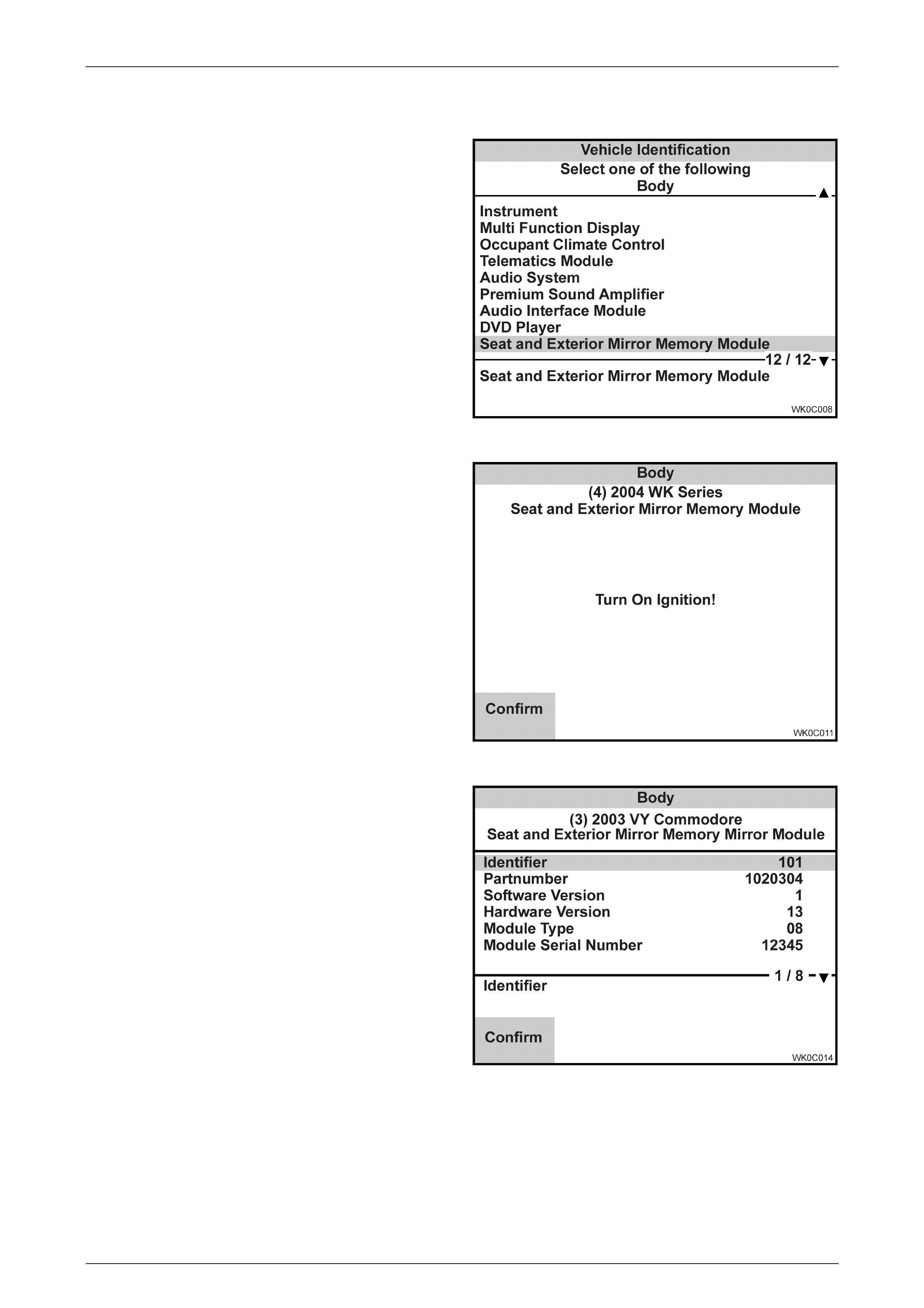
Seat and Exterior Mirror Memory Module
1 Select Seat and Exterior Mirror Memory Module
from the Vehicle Identification menu with the arrow
keys, then press ENTER.
Figure 0C-23 Vehicle Identification Menu
2 Turn on the ignition and press the Confirm soft
key.
The System Identification screen will then display
the following information:
Figure 0C-24 System Identification
Identifier
Partnumber
Software Version
Hardware Version
Module Type
Module Serial Number
Seat Assembly Serial Number
Date of Module Manufacture
3 Press the Confirm soft key, Seat and Exterior
Mirror Memory Module application menu will then
be displayed.
Figure 0C-25 System Identification
TECH 2 Page 0C–17
Page 0C–17
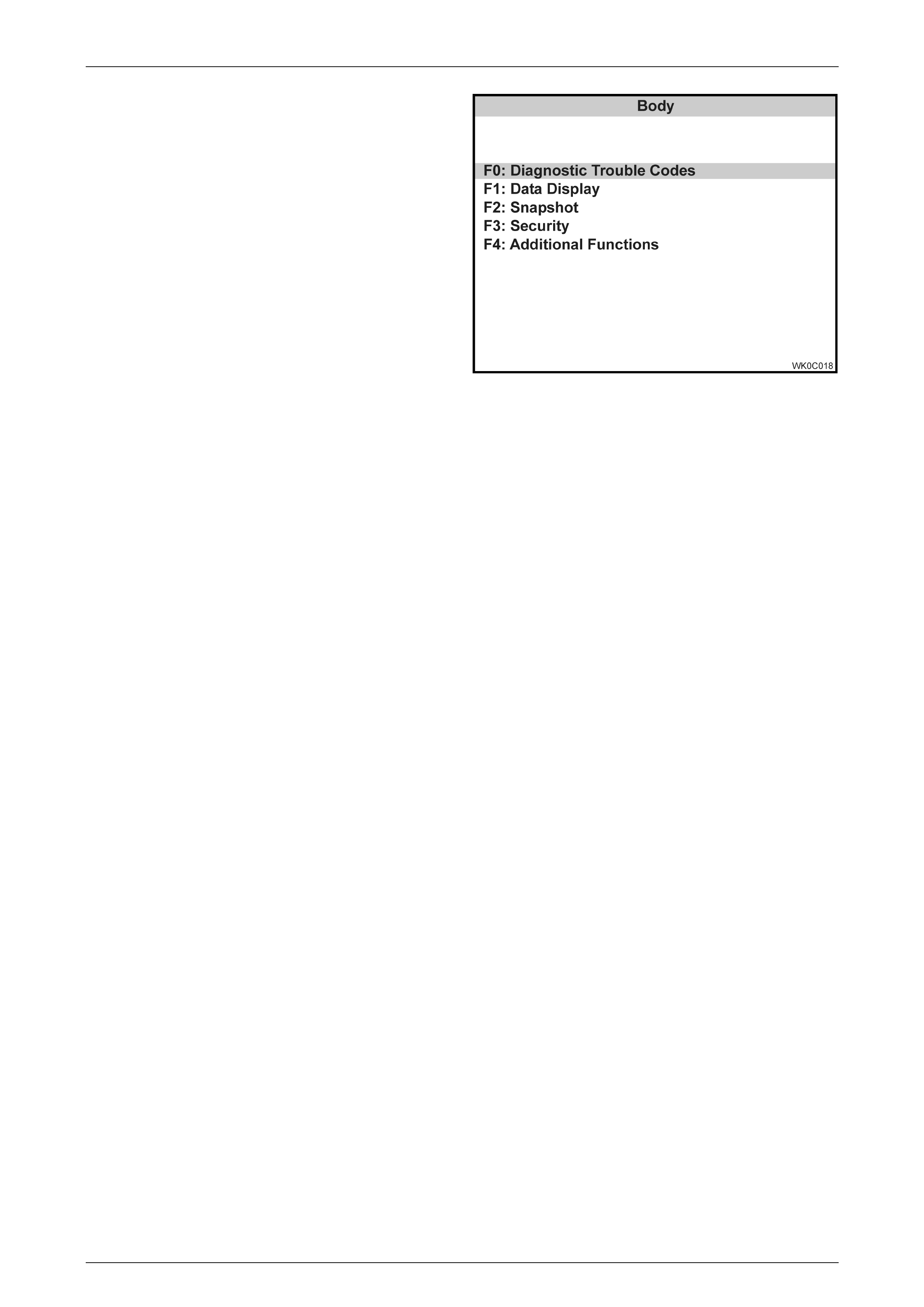
The following Seat and Exterior Mirror Memory
Module functions are available:
F0: Diagnostic Trouble Codes
F1: Data Display
F2: Snapshot
F3: Miscellaneous Tests
F4: Additional Functions
NOTE: Functions may vary depending on the
application selected. For further Seat and Exterior
Mirror Memory Module information refer to
Section 1A7 Seat Assemblies.
Figure 0C-26 DVD Player Application Menu
Diagnostic Trouble Codes
In this test mode, DTCs stored by the Seat and Exterior Mirror Memory Module can be displayed or cleared. When F1:
Diagnostic Trouble Codes is selected there is an additional two modes:
F0: Read DTC Information: If this mode is selected, a listing of all (if any) DTCs that have been set will be displayed.
Information displayed with the DTC number/s that have been set is; a short description of the DTC, if the DTC is current
(fault present) or history (stored, but not necessarily present on this ignition cycle), the number of times the DTC has
Occurred and the Ignition Cycles since the DTC was last set.
F1: Clear DTC Information: Once F1: Clear DTC Information has been selected, DTCs can be cleared by simply pressing
the Yes soft key.
Data Display
Inputs and Outputs
In this test mode, TECH 2 displays the status of inputs and outputs of the Seat and Exterior Mirror Memory Module.
Memory
In this test mode, TECH 2 displays the current driver’s seat position memory locations.
System Identification
In this test mode, the TECH 2 displays the Seat and Exterior Mirror Memory Module identification information. This data
list is the same as the information displayed on the system identification screen.
Snapshot
In this test mode, TECH 2 captures the data list information before and after a selected trigger point. The purpose of the
snapshot test mode is to help isolate an intermittent or transient problem by storing instrument data parameters just
before and just after a problem occurs.
Miscellaneous Tests
Miscellaneous Tests allows for the testing of the Seat and Exterior Mirror Memory Module to assist in problem isolation
during trouble shooting. When this mode is selected, the following options will become available. To exit any
miscellaneous test, press the Quit soft key or the EXIT key.
Chime
Precondition: None.
This miscellaneous test allows the technician to control the Seat and Exterior Mirror Memory Module chime. This is
achieved by using the Off and On soft keys.
LED
Precondition: None.
This miscellaneous test allows the technician to control the Seat and Exterior Mirror Memory Module LED . This is
achieved by using the Flash soft key. When the Flash soft key is pressed the LED will flash on and off eight times.

TECH 2 Page 0C–18
Page 0C–18
Right Exterior Mirror
Precondition: None.
This miscellaneous test allows the technician to control the Right Exterior Mirror. This is achieved by using the Left,
Right, Up and Down arrow keys. Each key press will allow two seconds of mirror movement.
Left Exterior Mirror
Precondition: None.
This miscellaneous test allows the technician to control the Left Exterior Mirror using the Left, Right, Up and Down arrow
keys. Each key press will allow two seconds of mirror movement.
Front Vertical Motor
Precondition: Igni tion Off.
This miscellaneous test allows the technician to control the front vertical motor either up or down using the Up and Down
soft keys. Each soft key press will allow two seconds of seat movement.
Rear Vertical Motor
Precondition: Igni tion Off.
This miscellaneous test allows the technician to control the rear vertical using the Up and Down soft keys. Each soft key
press will allow two seconds of seat movement.
Horizontal Motor
Precondition: Igni tion Off.
This miscellaneous test allows the technician to control the horizontal motor using the Back and Forward soft keys. Each
soft key press will allow two seconds of seat movement.
Recline Motor
Precondition: Igni tion Off.
This miscellaneous test allows the technician to control the recline motor using the Back and Forward soft keys. Each
soft key press will allow two seconds of seat movement.
Additional Functions
Reset Module
This reset function will reset the Seat and Exterior Mirror Memory Module. Once reset all seat and mirror memory
locations will be erased.