
Body Page 1A1–1
Page 1A1–1
Section 1A1
Body
ATTENTION
Before performing any Service Operation or other procedure described in this Section, refer to Section 00
WARNINGS, CAUTIONS AND NOTES for correct workshop practices with regard to safety and/or property
damage.
1 General Description............................................................................................................................... 2
2 Service Operations................................................................................................................................3
2.1 Fuel Filler Door Cable Assembly, RHD.................................................................................................................3
Remove ...................................................................................................................................................................3
Reinstall ..................................................................................................................................................................4
2.2 Fuel Filler Door Cable Assembly, LHD.................................................................................................................5
Remove ...................................................................................................................................................................5
Disassemble ...........................................................................................................................................................6
Reinstall ..................................................................................................................................................................6
Diagnosis................................................................................................................................................................7
Wiring Schematic................................................................................................................................................7
Connector Views.................................................................................................................................................8
2.3 Front Suspension Strut Brace...............................................................................................................................9
Remove ...................................................................................................................................................................9
Reinstall ..................................................................................................................................................................9
3 Torque Wrench Specifications........................................................................................................... 10

Body Page 1A1–2
Page 1A1–2
1 General Description
With the following exceptions, MY 2004 WK Series Body information carries over from MY 2003 VY Series vehicles. For
information not contained within this Section, refer to Sect ion 1A1, Body, in the MY 2003 VY and V2 Series Service
Information.
• Fuel filler door cable assembly.
• Front suspension strut brace assembly on Level 5 Models.
A new design fuel filler door cable is fitted to MY 2004 WK Series vehicles. Attachment is with two screws and a bracket
from within the fuel filler housing. Buffers are attached to the fuel filler door cable bracket to prevent damage to the fuel
filler door.
LHD vehicles also use this style cable which is attached to an actuator assembly in the rear compartment. A release
switch is on the instrument panel similar to VY Series vehicles.
Body Page 1A1–3
Page 1A1–3
2 Service Operations
2.1 Fuel Filler Door Cable Assembly, RHD
LT Section No. – 03-028
If required, first remove the following components:
1 Right-hand side sill trim and seat adjuster outer front cover, refer to Section 1A8, 2.2 Side Sill Trim & Plate in the
MY 2003 VY and V2 Series Service Information.
2 Rear seat cushion assemblies, refer to Section 1A7, Seat Assemblies.
3 Right-hand quarter inner rear side carpet, refer to Section 1A8, 2.7 Quarter Inner Rear Side Carpet.
Remove
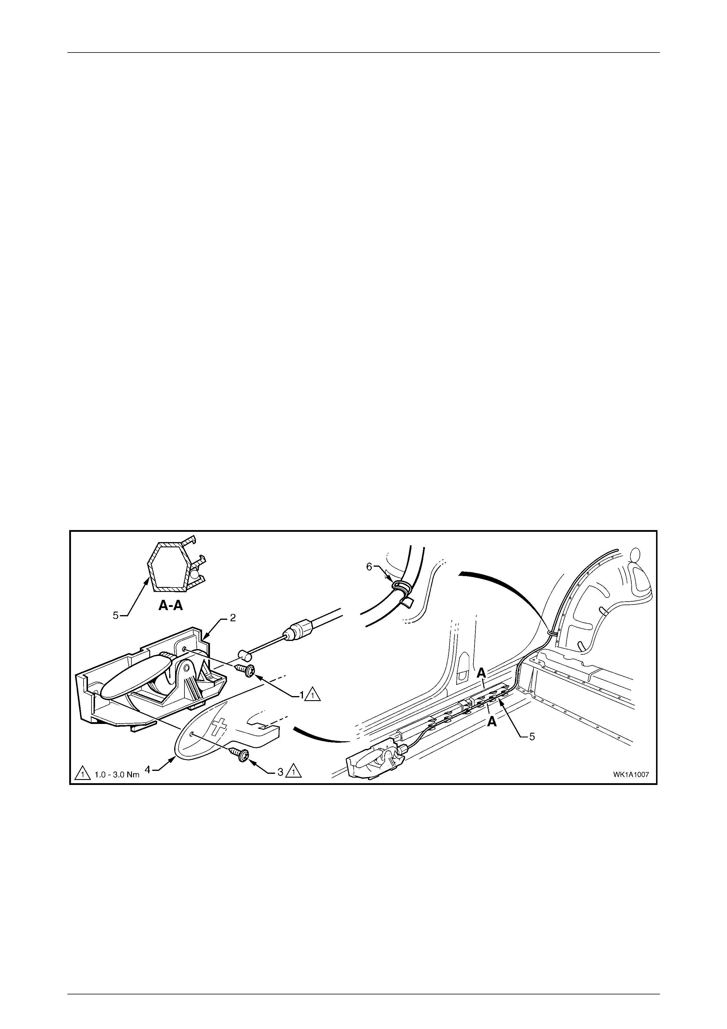
1 Open the fuel filler door by operating the release lever.
2 From inside the vehicle, remove the screw (1) attaching the cable assembly lever (2) to the rocker panel, refer to
Figure 1A1 – 1.
NOTE
The previously removed screw (3) attaches the
seat adjuster outer front cover (4) and the cable
assembly lever.
3 Unclip the cable from the harness formers (5), six places, and bend the retaining tab (6) to release the cable
assembly.
4 Unclip the cable from the release lever.
Figure 1A1 – 1
Body Page 1A1–4
Page 1A1–4
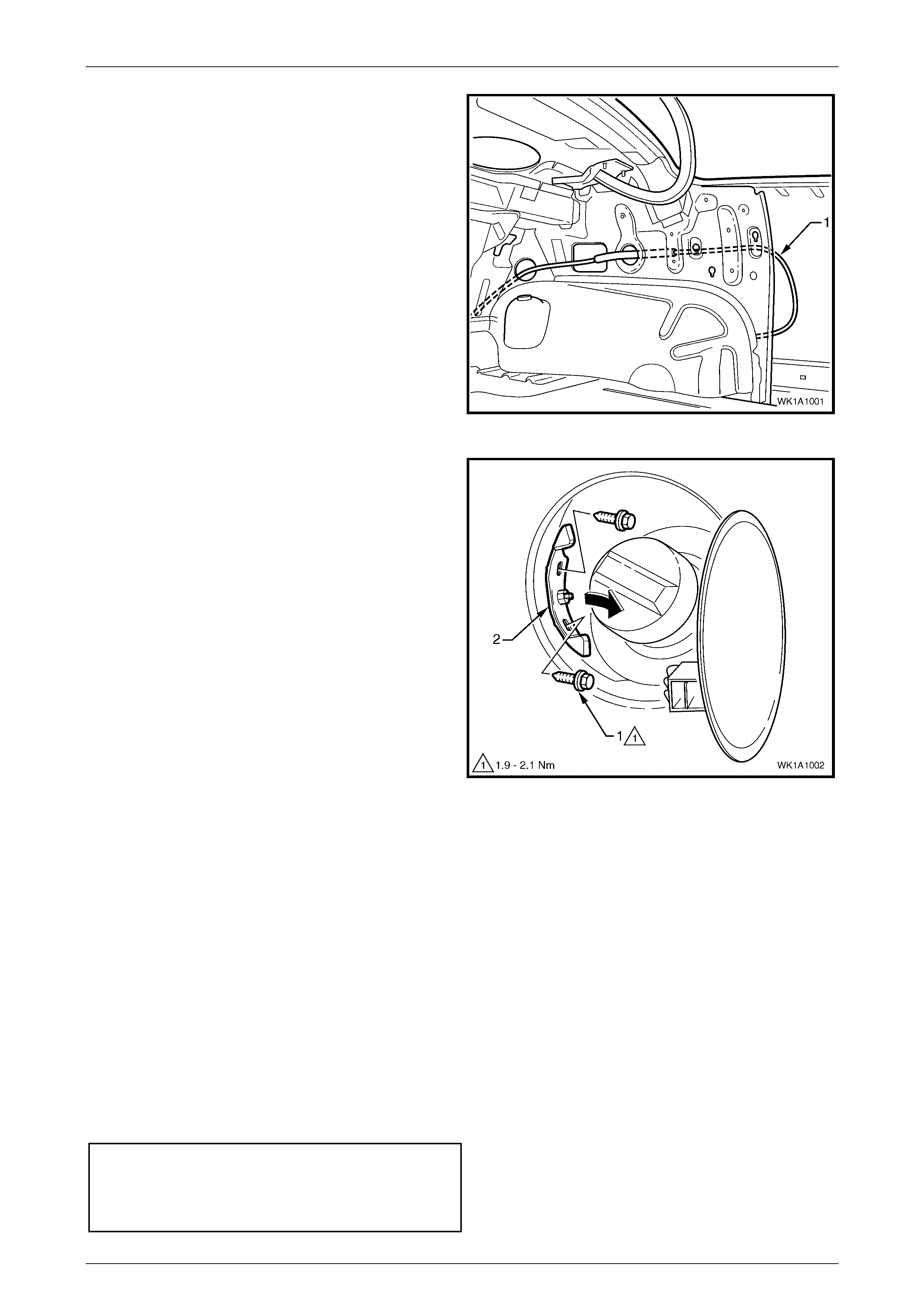
5 Pull the cable (1) through the back panel upper into
the rear compartment.
Figure 1A1 – 2
6 From within the fuel filler housing, remove the two
screws (1) attaching the cable assembly retainer (2).
7 Withdraw the cable assembly from the fuel filler
housing.
Figure 1A1 – 3
Reinstall
1 Installation is the reverse of removal. Ensure the components are tightened to the specified torque.
NOTE
Ensure the cable assembly is routed correctly as
shown in Figure 1A1 – 2.
NOTE
Ensure the cable assembly operates correctly
and the plunger completely retracts prior to
closing the fuel filler door. If satisfactory, close
the door ensuring it does not require excess
force. The door should spring ajar when the
release is operated.
Fuel filler door cable assembly release lever
attaching screw torque specification.......... 1.0 – 3.0 N.m
Fuel filler door cable assembly attaching
screw torque specification.........................1.9 – 2.1 N.m
Body Page 1A1–5
Page 1A1–5
2.2 Fuel Filler Door Cable Assembly, LHD
LT Section No.-03-028
NOTE
For removal of the fuel filler door switch
assembly, refer to the disassembly procedure in
Section 1A3, 3.12 Instrument Cluster Trim
Assembly.
If required, first remove the right-hand quarter inner rear side carpet, refer to Section 1A8, 2.7 Quarter Inner Rear Side
Carpet.
Remove
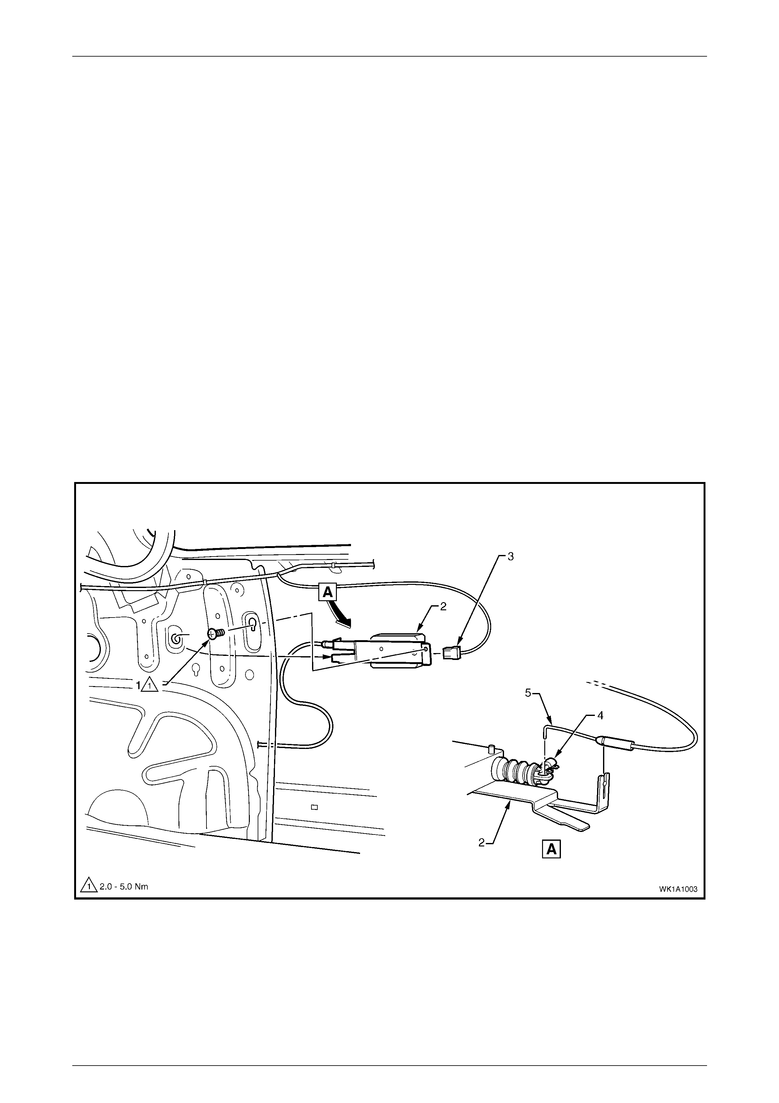
1 Open the fuel filler door by operating the fuel filler door switch on the instrument panel.
2 Loosen or remove the screw (1) attaching the actuator assembly (2) to the side panel inner, refer to Figure 1A1 – 4.
3 Slide the front of the assembly up and remove from the keyhole.
4 Withdraw the rear tab from its locating hole.
5 Disconnect the wiring connector (3).
6 Unclip the retainer (4) and remove the cable (5) from the actuator.
Figure 1A1 – 4
Body Page 1A1–6
Page 1A1–6
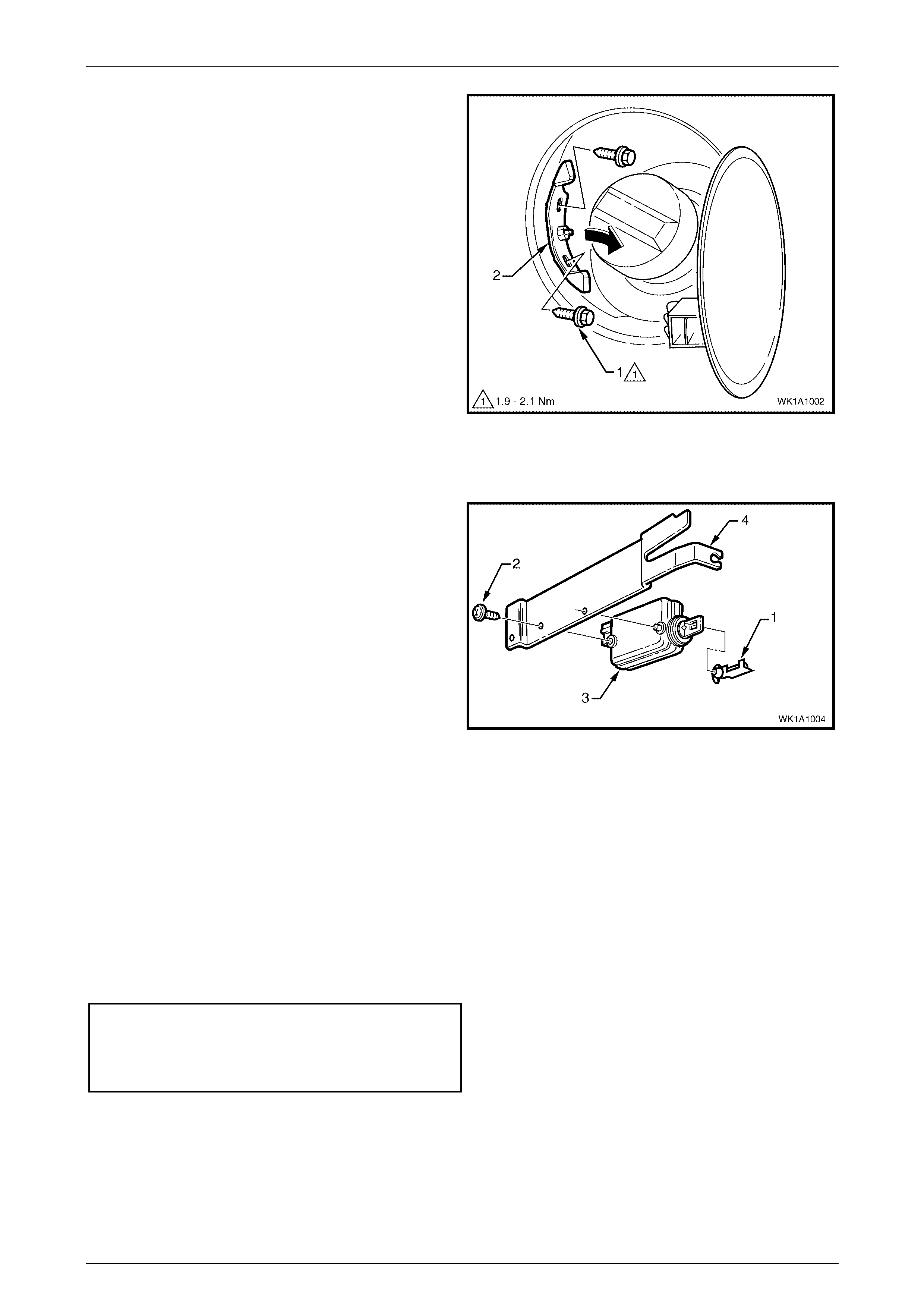
7 From within the fuel filler housing, remove the two
screws (1) attaching the cable assembly retainer (2).
8 Withdraw the cable assembly from the fuel filler
housing.
Figure 1A1 – 5
Disassemble
1 Unclip the retainer (1) from the cable end by raising
the locking tab.
2 Remove the screw (2) attaching the actuator (3) to the
mounting plate (4).
Figure 1A1 – 6
Reinstall
1 Installation is the reverse of removal. Ensure the components are tightened to the specified torque.
NOTE
Ensure the actuator assembly operates correctly
and the plunger completely retracts prior to
closing the fuel filler door. If satisfactory, close
the door ensuring it does not require excess
force. The door should spring ajar when the
release is operated.
Fuel filler door cable assembly actuator
attaching screw torque specification.......... 2.0 – 5.0 N.m
Fuel filler door cable assembly attaching
screw torque specification.........................1.9 – 2.1 N.m
Body Page 1A1–7
Page 1A1–7
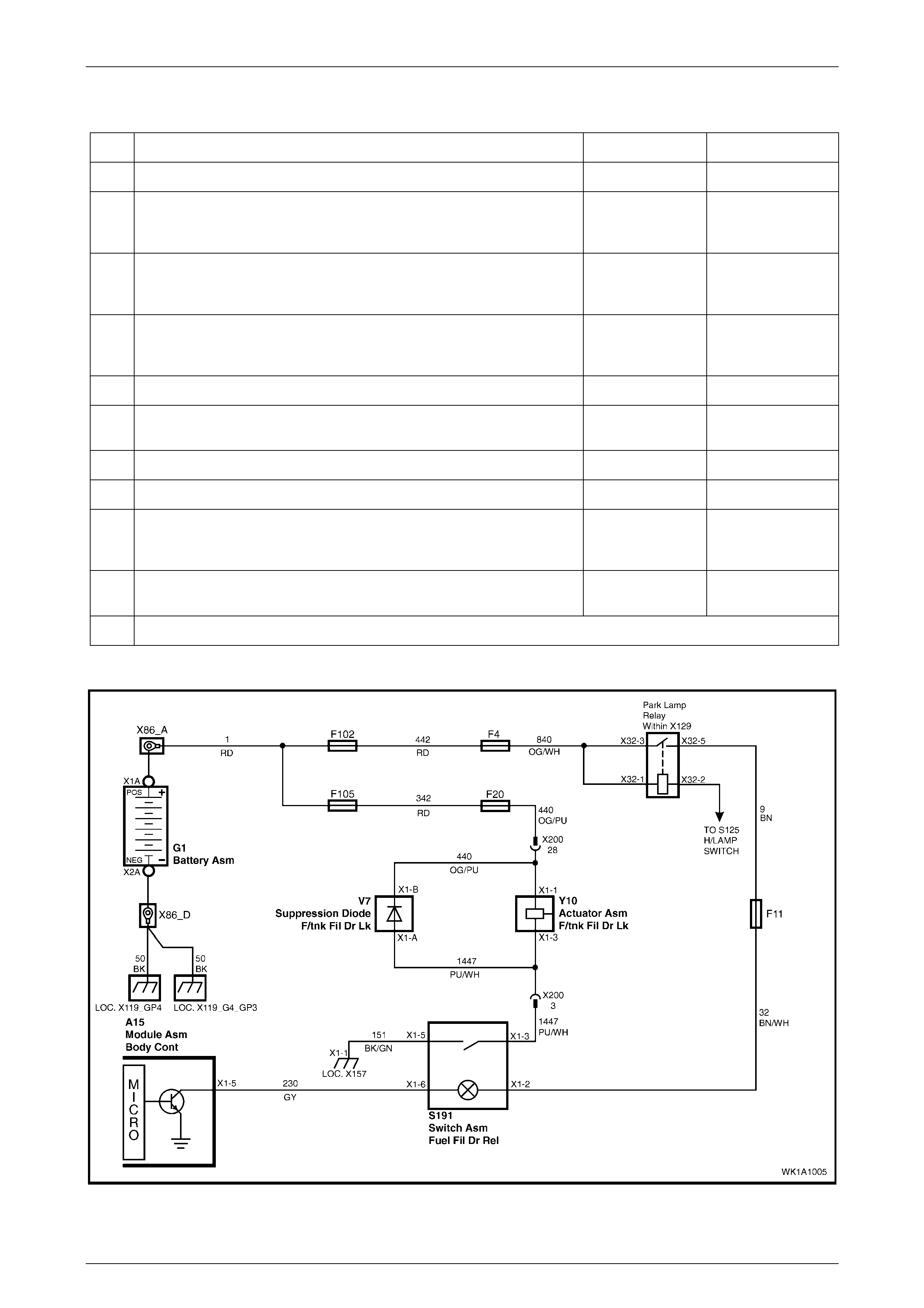
Diagnosis
Step Action Yes No
1 Press the filler door release switch. Does the fuel filler door open? OK. End Go to 2
2 Press the fuel filler door release switch. Does the actuator emit a
clicking sound? Door jammed or
cable is broken.
Repair or replace
Go to 3
3 Check Fuse 105 in the engine compartment fuse and relay panel
assembly. Is it OK? Go to 4 Replace fuse. If it
blows again test for
a short to ground
4 Check Fuse 20 in the passenger compartment fuse and relay panel
assembly. Is it OK? Go to 5 Replace fuse. If it
blows again test for
a short to ground
5 Ground the switch connector S191 pin 3. Does the actuator operate? Go to 6 Go to 7
6 Ground the switch connector S191 pin 5 and press the switch. Does
the actuator operate? Repair circuit 151 Replace switch *
7 Ground connector Y10 pin 3. Does the actuator operate? Repair circuit 1447 Go to 8
8 Check for B+ at the actuator connector Y10 pin 1 Replace actuator Go to 9
9 Check for B+ at connector X42 pin 22 in the passenger compartment
fuse and relay panel assembly Repair circuit 440
between fuse 20
and the actuator
Go to 10
10 Check for B+ at connector X18 pin 104 in the engine compartment fuse
and relay panel assembly Repair circuit 342 Repair circuit 1
* Also check the suppression diode for continuity between pins A to B but not B to A
Wiring Schematic
Figure 1A1 – 7
Body Page 1A1–8
Page 1A1–8
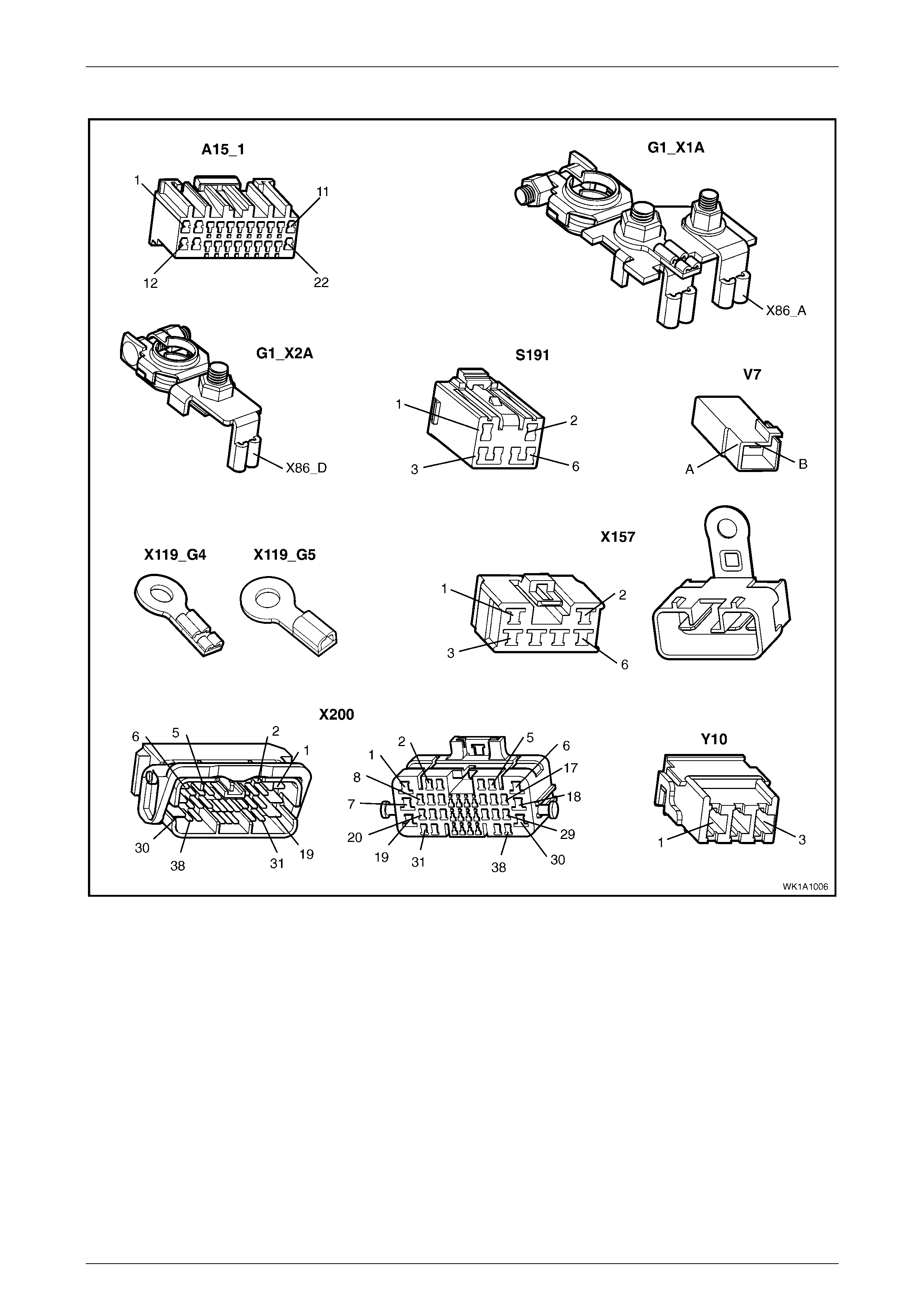
Connector Views
Figure 1A1 – 8
Body Page 1A1–9
Page 1A1–9
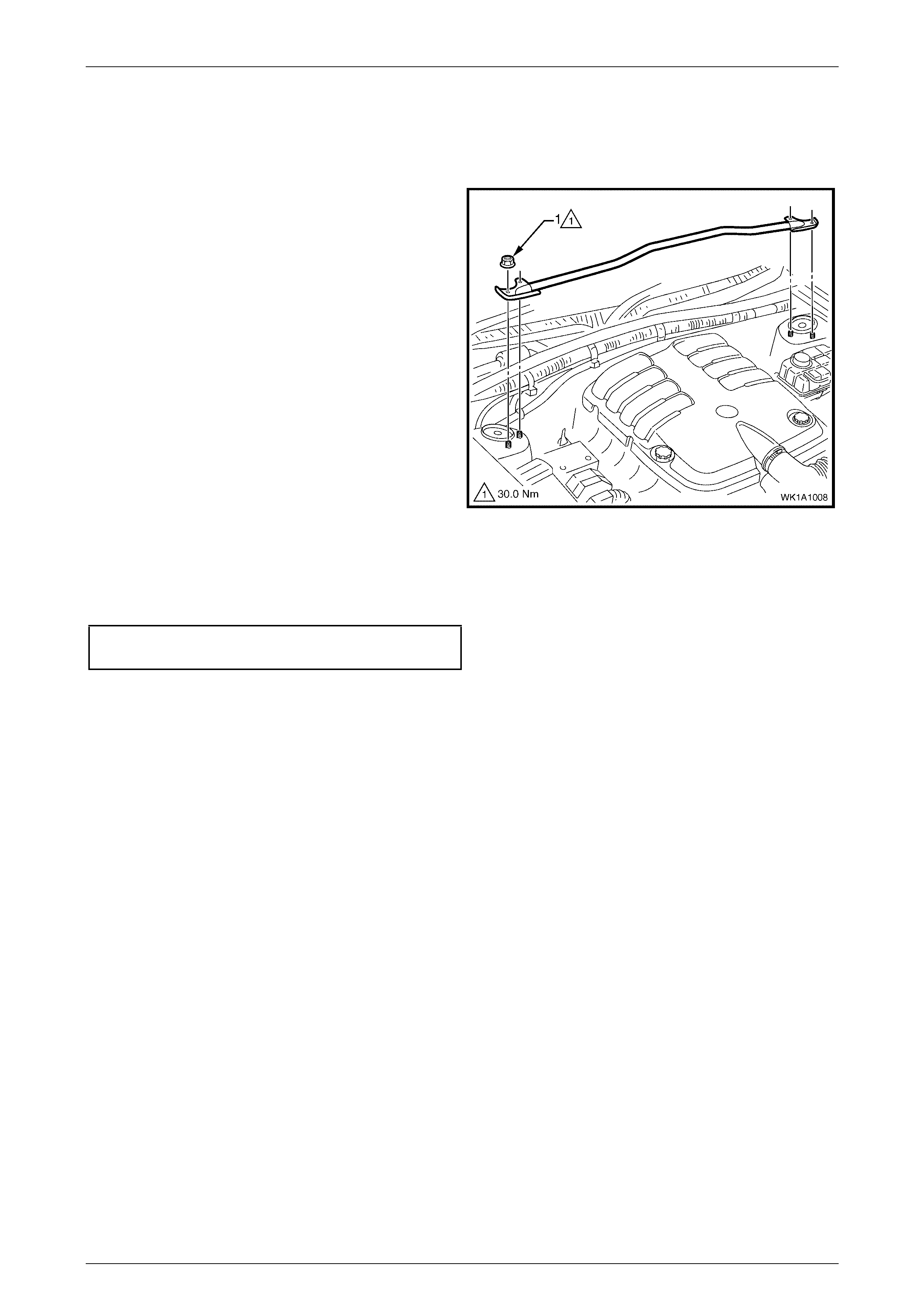
2.3 Front Suspension Strut Brace
Remove
1 Remove the nuts (1), four places, attaching the front
suspension strut brace to the suspension strut towers.
2 Remove the brace from the towers.
Figure 1A1– 9
Reinstall
Reinstallation is the reverse of removal. Ensure the components are tightened to the specified torque.
Front Suspension Strut Brace
Attaching Nut Torque Specification.....................30 N.m

Body Page 1A1–10
Page 1A1–10
3 Torque Wrench Specifications
Fuel filler door cable assembly attaching screw............................1.9 – 2.1 N.m
Fuel filler door cable assembly release lever attaching screw......1.0 – 3.0 N.m
Fuel filler door cable assembly actuator attaching screw .............2.0 – 5.0 N.m
Front Suspension Strut Brace Attaching Nut Torque Specification.........30 N.m