
Instrument P anel and Console Page 1A3–1
01–Oct–2002 Page 1A3–1
Section 1A3
Instrument Panel and Console
ATTENTION
Before performing any Service Operation or other procedure described in this Section, refer to Section 00
WARNINGS, CAUTIONS AND NOTES for correct workshop practices with regard to safety and/or property
damage.
1 General Information............................................................................................................................... 2
1.1 Instrument Panel and Console Components.......................................................................................................2
Floor Console Components ..................................................................................................................................3
Instrument Panel Components .............................................................................................................................4
2 Service Operations – Floor Console.................................................................................................... 6
2.1 Auxiliary Switch Liner or Auxiliary Switch and Bezel.........................................................................................6
Remove ...................................................................................................................................................................6
Reinstall ..................................................................................................................................................................6
3. Service Operations – Instrument Panel............................................................................................... 7
3.1 Instrument Panel Centre Trim Assembly.............................................................................................................7
Remove ...................................................................................................................................................................7
Disassemble ...........................................................................................................................................................8
OCC Control Module and Cup Holder Assembly................................................................................................8
Centre Air Outlet Housing and Multi-function Display.........................................................................................8
Assemble ................................................................................................................................................................9
Reinstall ..................................................................................................................................................................9
3.2 Windshield Defroster Grille.................................................................................................................................10
Remove .................................................................................................................................................................10
Reinstall ................................................................................................................................................................10
3.3 Instrument Panel Compartment Dampener (Level 4 and 5 RHD only).............................................................11
Remove .................................................................................................................................................................11
Disassemble .........................................................................................................................................................11
Assemble ..............................................................................................................................................................12
Reinstall ................................................................................................................................................................12
4. Torque Wrench Specifications........................................................................................................... 13
Techline
Techline
Techline

Instrument P anel and Console Page 1A3–2
01–Oct–2002 Page 1A3–2
1 General Information
With the following exceptions, MY 2004 WK Series Instrument Panel and Console information carries over from MY 2003
VY Series vehicles. For Level 1 vehicles and for information not contained within this Section, refer to Sect ion 1A3
INSTRUMENT PANEL AND CONSOLE in the MY 2003 VY and V2 Series Service Information.
• For vehicles fitted with a multi-function display:
• Multi-function display is fitted to the centre fascia.
• Air vents are a different style.
• Hazard switch is relocated from the centre fascia to the console.
• Occupant Climate Control (OCC) is included instead of manual climate control.
• Instrument panel and defroster grille:
• New instrument panel and defroster grille.
• Instrument panel compartment damper is only fitted to RHD vehicles.
NOTE:
The information that is provided in this Section is
to be used for both left and right-hand drive
vehicles. Although the information shown is
primarily right-hand drive, it is to be mirrored for
left-hand drive vehicles unless otherwise
specified.
1.1 Instrument Panel and Console
Components
Refer to Figure 1A3 – 1 for an illustration of the floor console components and Figure 1A3 – 2 for the instrument panel
components. Note that these diagrams do not show switches or electrical components.
Instrument P anel and Console Page 1A3–3
01–Oct–2002 Page 1A3–3
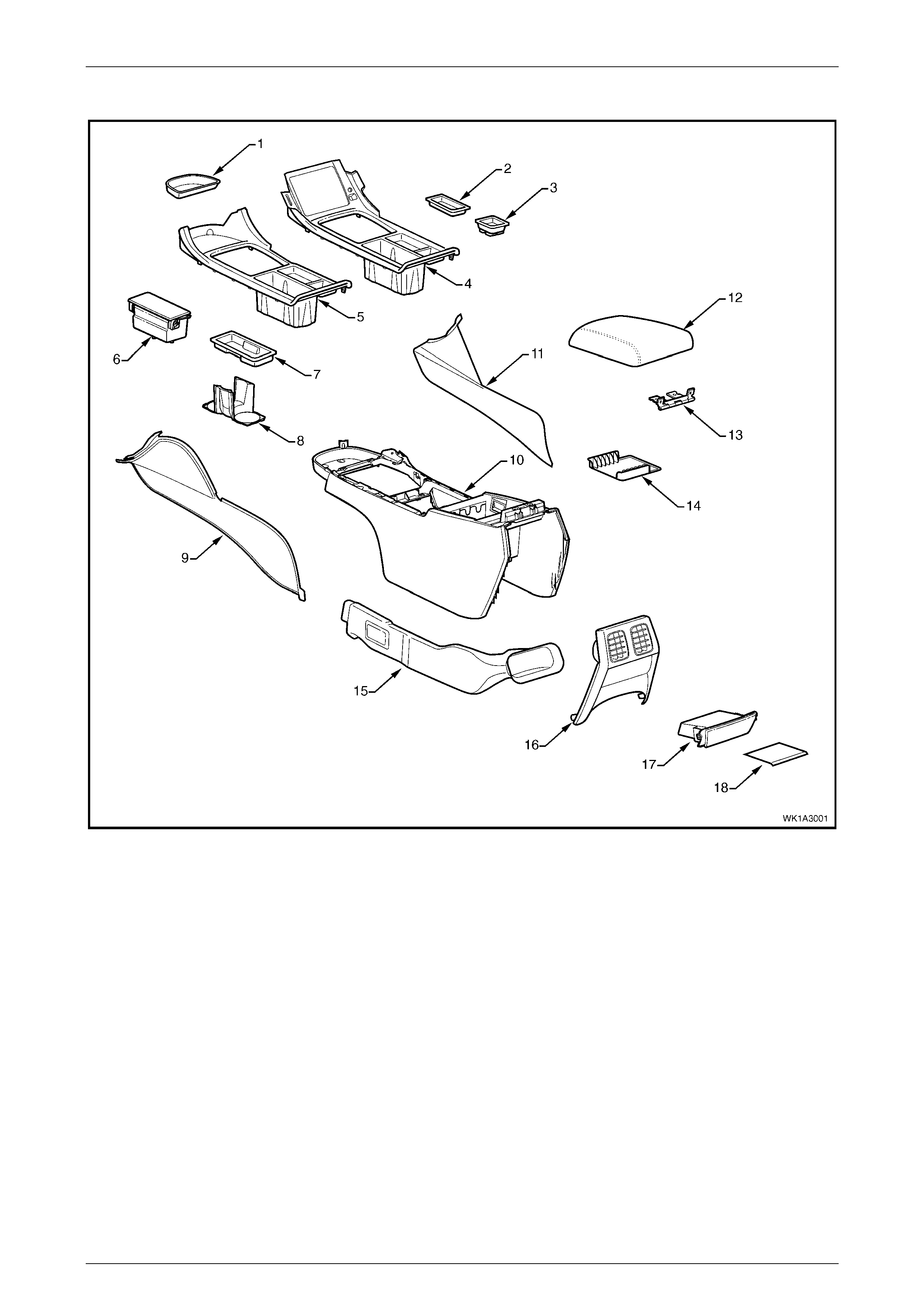
Floor Console Components
Figure 1A3 – 1
Legend
1 Floor Console Front Compartment Liner
2 Floor Console Liner (optional on Level 1)
3 Auxiliary Switch Liner (Level 1 only) or Bezel
4 Floor Console Cover (with Navigati on S ystem)
5 Floor Console Cover (without Navigati on System)
6 Mobile Phone Compartment (Level 4 and 5)
7 Floor Console Storage Tray, Where Fitted
8 Cup Holder, (Level 1, 2 and 3)
9 Instrument P anel Lower Extension Side Trim, LH
10 Floor Console
11 Instrument P anel Lower Extension Side Trim, RH
12 Armrest Assembly
13 Floor Console Compartment Armrest Hinge
14 Floor Console Compartment Liner
15 Floor Console Rear Air Duct
16 Floor Console Rear Upper Compartment Assembly
17 Floor Console Rear Compartm ent or Ashtray Assem bl y
18 Floor Console Rear Compartment Liner
Instrument P anel and Console Page 1A3–4
01–Oct–2002 Page 1A3–4
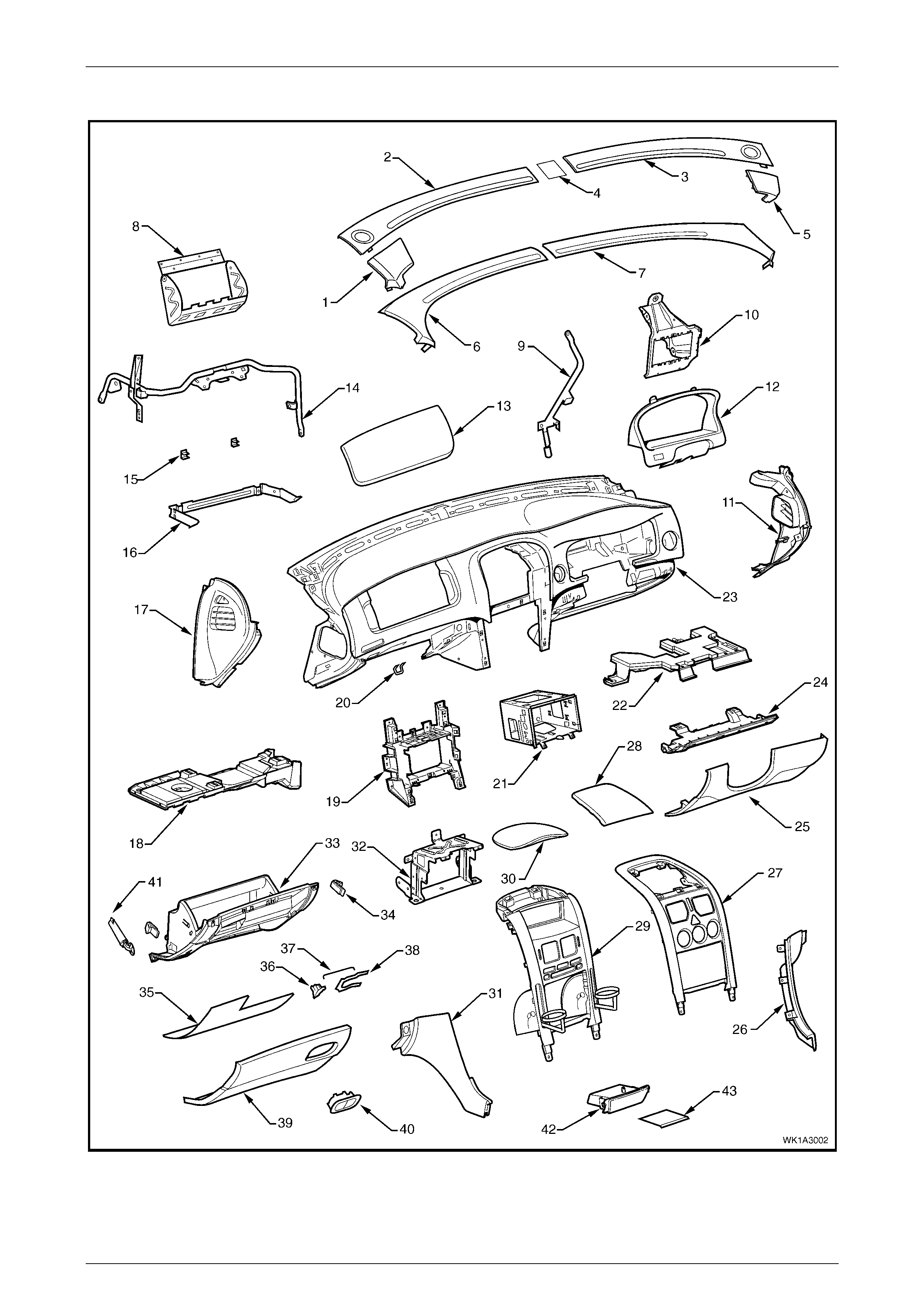
Instrument Panel Components
Figure 1A3 – 2

Instrument P anel and Console Page 1A3–5
01–Oct–2002 Page 1A3–5
Legend
1 Extension Pad, LH (Level 2 to 5)
2 Windshield Defroster Grille, LH (Level 2 to 5)
3 Windshield Defroster Grille, RH (Level 2 to 5)
4 Solar Sensor (Level 2 to 5)
5 Extension Pad, RH (Level 2 to 5)
6 Windshield Defroster Grille, RH (Level 1)
7 Windshield Defroster Grille, LH (Level 1)
8 Instrument P anel Inflat abl e Restraint Bracket
9 Steering Column Bracket Inner Brace
10 Steering Colum n Brack et Outer Brace
11 Instrument P anel Outer Cover, RH
12 Instrument Cluster Trim Assembly
13 Instrument P anel Inflat abl e Rest raint Openi ng Trim Cover
14 Instrument P anel Lower Brack et
15 Instrument P anel Compartment Hinge
16 Instrument Panel Compartment Bracket
17 Instrument P anel Outer Cover, LH
18 Instrument P anel Lower Trim Plate Assembly, LH
19 Radio Bracket Assembly
20 Instrument P anel Compartment Lock Striker
21 Radio Housing
22 Instrument P anel Lower Trim Plate Assembly, RH
23 Instrument Panel Pad Assembly
24 Instrument P anel Lower Trim Panel Retainer
25 Instrument Panel Lower Trim Panel Assembly
26 Instrument P anel Lower Extension, RH
27 Instrument P anel Centre Trim Assembly (Level 1)
28 Instrument P anel Upper Centre Trim Panel (Level 1)
29 Instrument P anel Centre Trim Assembly (Level 2 to 5)
30 Instrument P anel Upper Centre Trim Panel (Level 2 to 5)
31 Instrument P anel Lower Extension, LH
32 Lower Radio Bracket
33 Instrument P anel Compartment
34 Instrument P anel Compartment Bumper Stop
35 Instrument P anel Compartment Liner
36 Instrument P anel Compartment Latch Assembly
37 Instrument P anel Compartment Latch Rod
38 Instrument P anel Compartment Latch Retainer
39 Instrument P anel Compartment Door
40 Instrument P anel Compartment Latch Actuator
41 Instrument P anel Compartment Dampener (Level 4 and 5
RHD only)
42 Instrument P anel Lower Compartment or Ashtray
Assembly
43 Instrument P anel Lower Compartm ent Li ner
Instrument P anel and Console Page 1A3–6
01–Oct–2002 Page 1A3–6
2 Service Operations – Floor
Consol e
2.1 Auxiliary Switch Liner or Auxiliary
Switch and Bezel
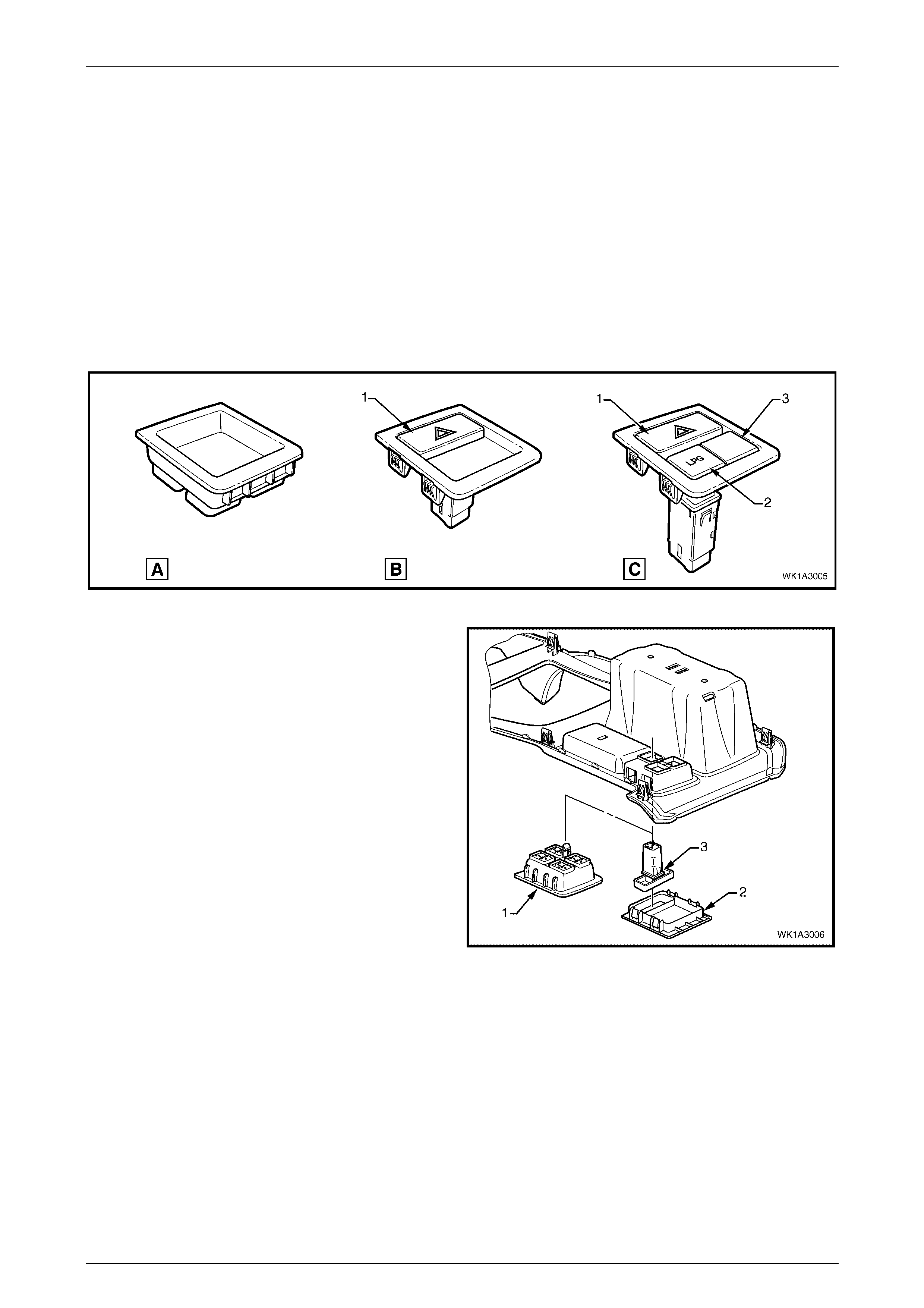
Depending on options fitted, the location shown in Figure 1A3 – 3 will be fitted with:
1 An auxiliary switch liner (A) where no auxiliary switches are fitted,
2 A one cavity auxiliary switch bezel (B) when fitted with a hazard warning switch (1) only, or
3 A three cavities auxiliary switch bezel (C) when fitted with a hazard warning switch (1) and a LPG switch (2). In this
configuration, the empty cavity is fitted with a switch blank (3).
Figure 1A3 – 3
Remove
1. To remove the auxiliary switch liner (1), disengage
the retaining lug securing the liner to the cover
assembly.
2. To remove the auxiliary switch bezel (2), (one or three
cavity type), depress the four tabs securing the
auxiliary switch bezel to the cover assembly and
remove.
3. To remove a switch or blank, depress the two tabs
securing the switch or blank to the cover assembly
and remove the switch or blank.
NOTE
The switches can only fit in the one location as
shown in Figure 1A3 – 3.
Reinstall
1. Installation is the reverse of the removal procedure.
Figure 1A3 – 4
Instrument P anel and Console Page 1A3–7
01–Oct–2002 Page 1A3–7
3. Service Operations – Instrument
Panel
3.1 Instrument Panel Centre Trim Assembly
Remove
LT Section – 09-300
1 If required, remove the following navigation system equipment:
a Remote control cradle, refer to Section 12L NAVIGATION SYSTEM in the MY 2004 WK Series Service
Information.
b Navigation monitor escutcheon, refer to Section 12L NAVIGATION SYSTEM in the MY 2004 WK Series
Service Information.
2 Remove the floor console cover assembly, refer to 2.1 FLOOR CONSOLE COVER ASSEMBLY, Section 1A3
INSTRUMENT PANEL AND CONSOLE in the MY 2003 VY and V2 Series Service Information.
3 Remove the radio assembly, refer to 3.6 RADIO ASSEMBLY, Section 1A3 INSTRUMENT PANEL AND CONSOLE
in the MY 2003 VY and V2 Series Service Information.
Using tools to pry off components will
damage the instrument panel, the instrument
panel upper centre trim panel and/or the
centre trim assembly.
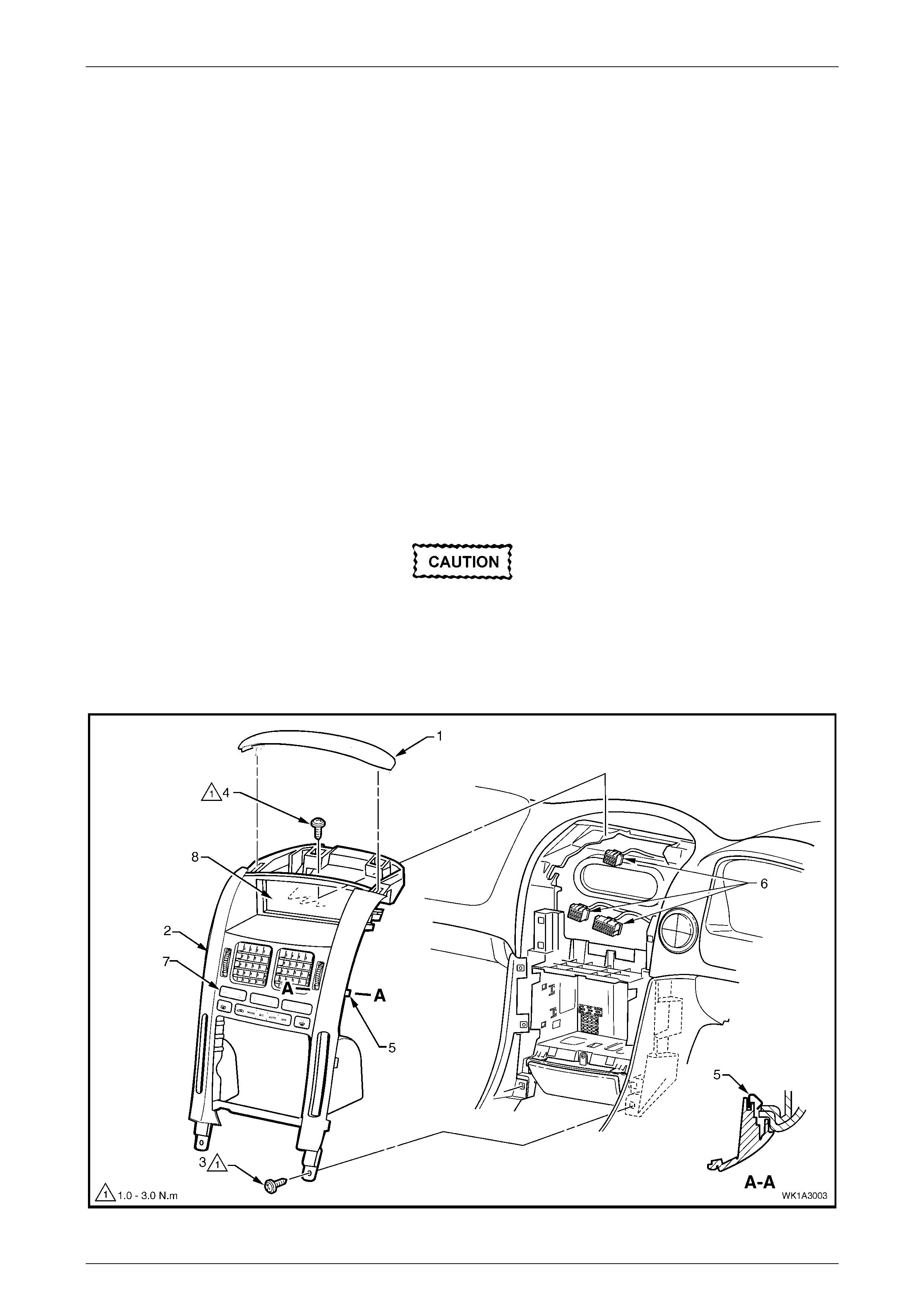
4 Carefully prise the front edge of the instrument panel upper centre trim panel (1), and pull upward to disengage the
retaining clips at each corner from the centre trim assembly (2), refer to Figure 1A3 – 5.
Figure 1A3 – 5
Instrument P anel and Console Page 1A3–8
01–Oct–2002 Page 1A3–8
5 Remove the lower screws (3), two places, attaching the centre trim assembly to the instrument panel, refer to
Figure 1A3 – 5.
6 Remove the upper screws (4), two places, attaching the centre trim assembly to the instrument panel, refer to
Figure 1A3 – 5.
7 Remove the centre trim assembly, disengaging the four clips (5), far enough to disconnect the wiring connectors
from the rear of the hazard warning switch and where fitted, the OCC control module, refer to Figure 1A3 – 5.
8 Remove the centre trim assembly.
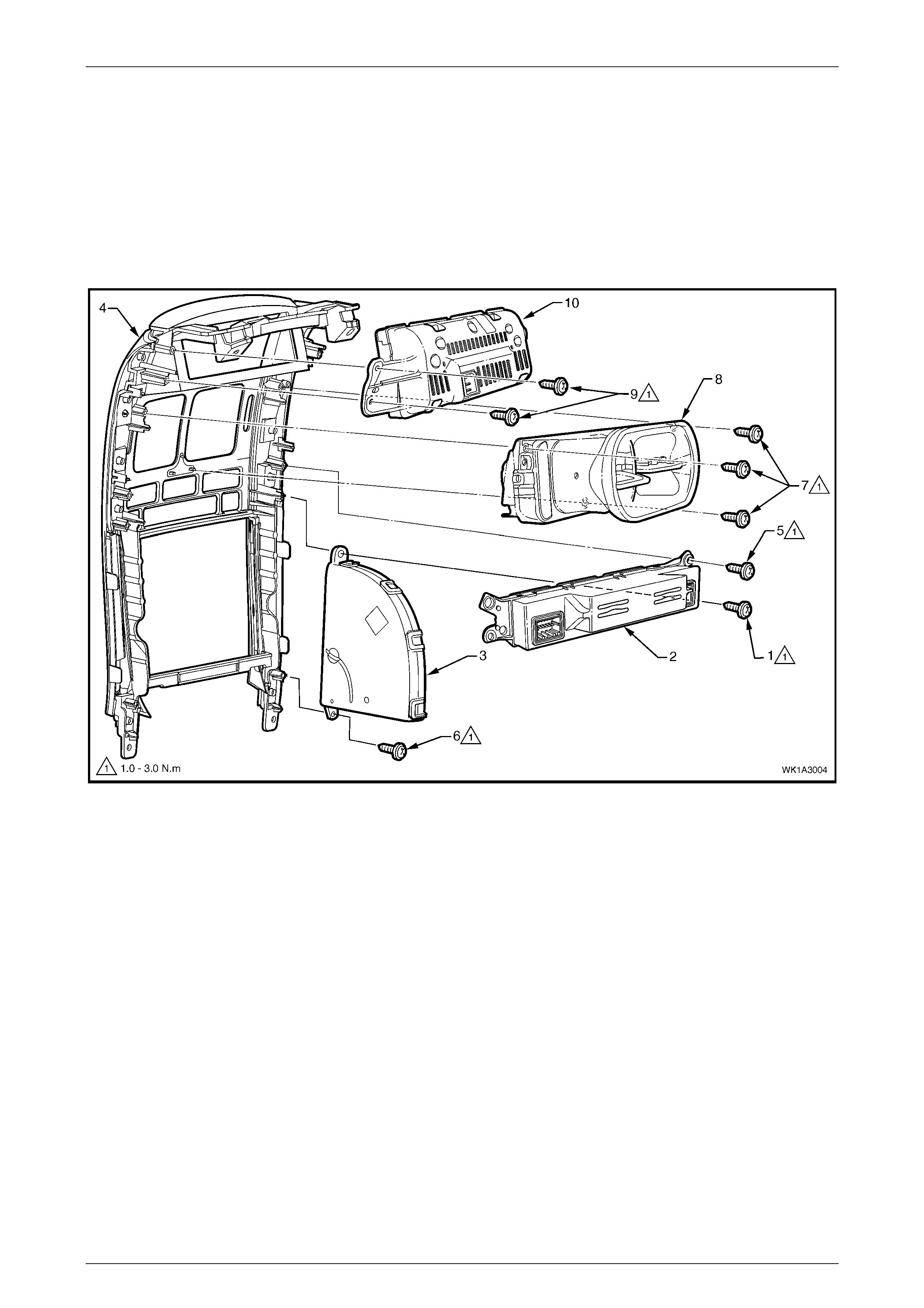
Disassemble
Figure 1A3 – 6
OCC Control Module and Cup Holder Assembly
1 Remove the screw (1), one place each side, attaching the OCC control module (2) and cup holder assembly (3) to
the centre trim (4), refer to Figure 1A3 – 6.
2 Remove the screw (5), one place each side, attaching the OCC control module to the centre trim and remove the
control modu le.
3 Remove the screw (6) attaching the cup holder assembly to the centre trim and remove the cup holder.
NOTE
For diagnosis of the OCC control module refer to
Section 2F HVAC OCCUPANT CLIMATE
CONTROL (AUTO A/C) – DIAGNOS TICS
Centre Air Outlet Housing and Multi-function Display
1 Remove the three screws (7) attaching the instrument panel centre air outlet housing assembly (8) to the centre
trim, refer to Figure 1A3 – 6.
2 Remove the four screws (9) attaching the multi-function display assembly (8) to the centre trim, refer to Figure 1A3
– 6.

Instrument P anel and Console Page 1A3–9
01–Oct–2002 Page 1A3–9
Assemble
Assembly is the reverse of the disassembly procedure. Tighten all screws to the specified torque.
Multi-function display attaching screw
torque specific atio n ...................................1.0 – 3.0 N.m
Instrument panel centre air outlet
housing assembly attaching screw
torque specific atio n ...................................1.0 – 3.0 N.m
Instrument panel cup holder assembly
attaching screw torque specification.......... 1.0 – 3.0 N.m
OCC control module attaching screw
torque specific atio n ...................................1.0 – 3.0 N.m
Reinstall
Installation is the reverse of the removal procedure. Tighten all screws to the specified torque.
Instrument panel centre trim assembly
attaching screw torque specification.......... 1.0 – 3.0 N.m
Instrument P anel and Console Page 1A3–10
01–Oct–2002 Page 1A3–10
3.2 Windshield Defroster Grille
Remove
LT Section – 09-125
1 Remove the instrument panel outer cover from the appropriate side(s), refer to 3.17 INSTRUMENT PANEL OUTER
COVER, Section 1A3 INSTRUMENT PANEL AND CONSOLE in the MY 2003 VY and V2 Series Service
Information.
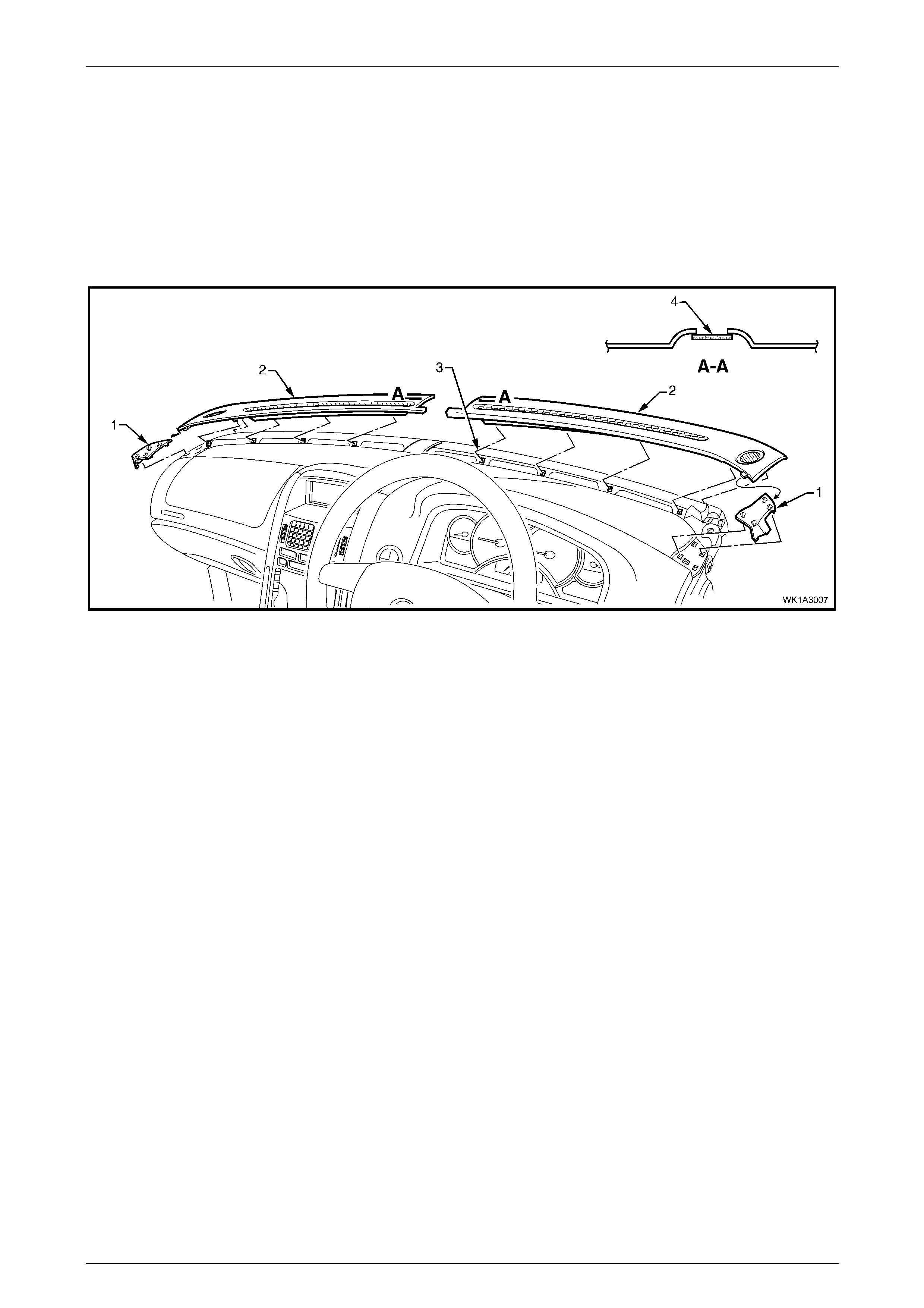
Figure 1A3 – 7
2 Remove the extension pad (1) from the appropriate side(s) by unclipping in four places, refer to Figure 1A3 – 7.
3 Carefully remove the grille (2) by unclipping (3), five places, at an angle equal to the windshield.
4 If required, remove the solar sensor (4).
Reinstall
Installation is the reverse of the removal procedure, noting the following:
1 Ensure the remote key receiver and headlamp auto control / solar sensor (4) is correctly seated prior to installing
the grille assembly.
2 Ensure the five clips are correctly seated before installing the extension pad.
Instrument P anel and Console Page 1A3–11
01–Oct–2002 Page 1A3–11
3.3 Instrument Panel Compartment
Dampener (Le vel 4 and 5 RHD only)
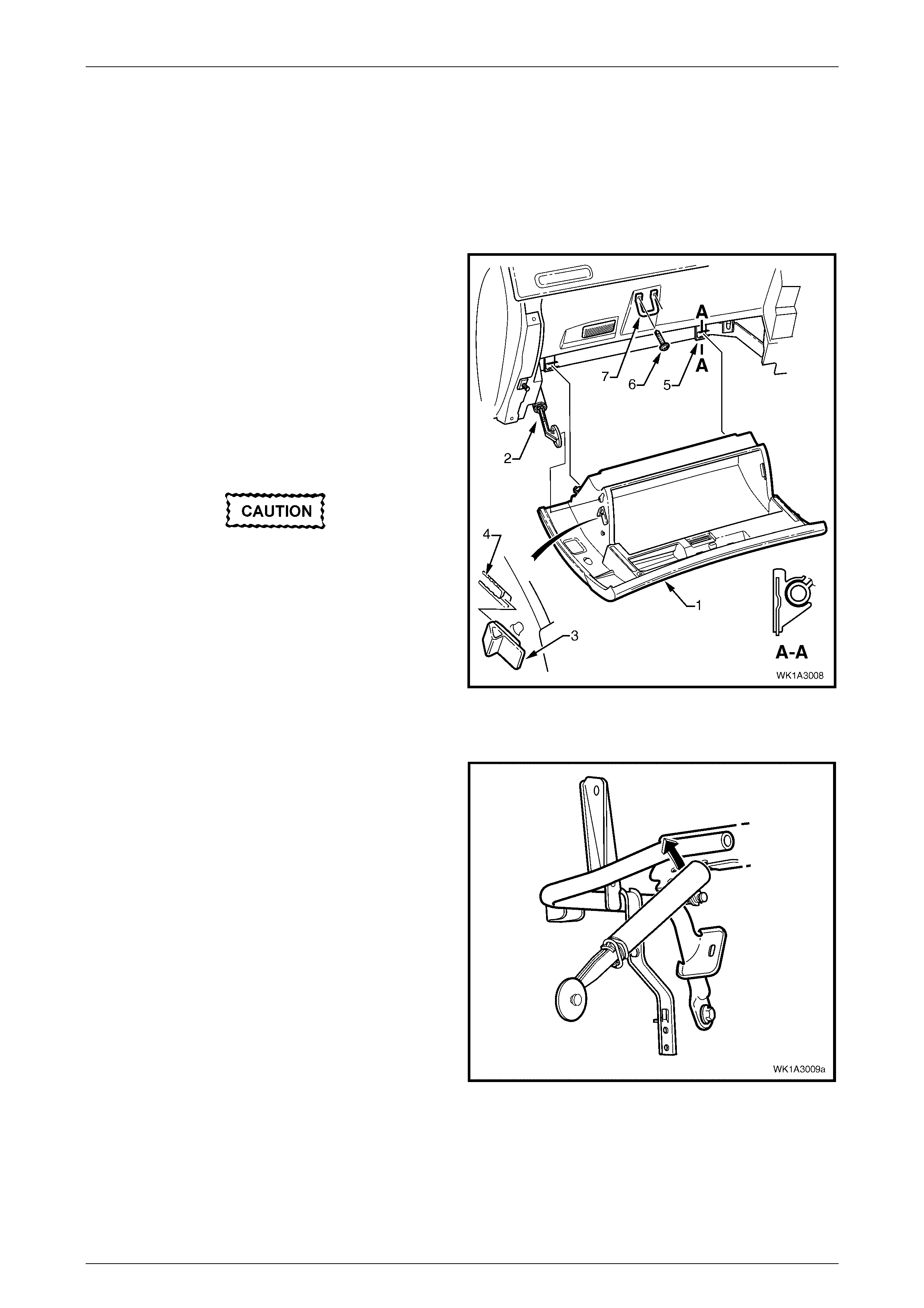
Remove
LT Section – 09-140
1 Open the instrument panel compartment assembly (1).
2 Unclip the dampener (2) from the instrument panel
compartment as se mbly .
3 Using a fine flat-blade screwdriver, flatten the
instrument panel compartment bumper stop (3) each
side, and carefully open the compartment assembly
fully.
4 As required, from the inside of the instrument panel
compartment assembly, push downwards on the
bumper stop, and slide the bumper from the lug (4).
Repeat for the opposite side.
Take care when disengaging the hinges as
removing the instrument panel compartment
assembly on the wrong angle may cause
damage.
5 Close the instrument pane l compartment asse mbly
half way and grasping each side pull rearward to
disengage the compartment assembly from each
instrument panel compartment hinge (5).
6 As required, remove the two screws (6) attaching the
instrument panel compartment lock striker (7) and
remove th e striker.
Figure 1A3 – 8
7 As required, pull to unclip the dampener from the
instrument panel lower bracket.
Figure 1A3 – 9
Disassemble
Refer to 3.2 INSTRUMENT PANEL COMPARTMENT ASSEMBLY, Section 1A3 INSTRUMENT PANEL AND CONSOLE
in the MY 2003 VY and V2 Series Service Information.

Instrument P anel and Console Page 1A3–12
01–Oct–2002 Page 1A3–12
Assemble
Refer to 3.2 INSTRUMENT PANEL COMPARTMENT ASSEMBLY, Section 1A3 INSTRUMENT PANEL AND CONSOLE
in the MY 2003 VY and V2 Series Service Information.
Reinstall
Installation of the instrument panel compartment assembly is the reverse of removal. As required, adjust the instrument
panel compartment lock striker to provide secure closing of the instrument panel compartment and tighten the screws to
the specified torque.
Instrument panel compartment lock striker
attaching screw torque specification.......... 1.0 – 3.0 N.m

Instrument P anel and Console Page 1A3–13
01–Oct–2002 Page 1A3–13
4. Torque Wrench Specifications
Instrument panel cup holder assembly attaching screw................1.0 – 3.0 N.m
OCC control module attaching screw ...........................................1.0 – 3.0 N.m
Instrument panel centre air outlet housing assembly
attaching screw.............................................................................1.0 – 3.0 N.m
Multi-function display attaching screw...........................................1.0 – 3.0 N.m
Instrument panel centre trim assembly attaching screw...............1.0 – 3.0 N.m
Instrument panel compartment lock striker attaching screw.........1.0 – 3.0 N.m