
Hood, Rear Com part ment Lid, Li f tgate & Endgate Page 1A4–1
Page 1A4–1
Section 1A4
Hood, Rear Compartment Lid, Liftgate & Endgate
ATTENTION
Before performing any Service Operation or other procedure described in this Section, refer to Section 00
Warnings, Cautions And Notes for correct workshop practices with regard to safety and/or property damage.
1 General Description............................................................................................................................... 2
2 Service Operations – Hood................................................................................................................... 3
2.1 Hood Secondary Lock Lever Assembly...............................................................................................................3
Remove ...................................................................................................................................................................3
Reinstall..................................................................................................................................................................3
2.2 Hood Secondary Latch Assembly.........................................................................................................................4
Remove ...................................................................................................................................................................4
Reinstall..................................................................................................................................................................5
3 Service Operations – Rear Compartment Lid ..................................................................................... 6
3.1 Rear Compartment Lid Safety Triangle................................................................................................................6
Remove ...................................................................................................................................................................6
Reinstall..................................................................................................................................................................6
3.2 Rear Compartment Lid Carpet..............................................................................................................................7
Remove ...................................................................................................................................................................7
Reinstall..................................................................................................................................................................7
3.3 Rear Spoiler Assembly..........................................................................................................................................8
Remove ...................................................................................................................................................................8
Reinstall..................................................................................................................................................................8
3.4 Rear Compartment Lid Assembly.......................................................................................................................10
Remove .................................................................................................................................................................10
Reinstall................................................................................................................................................................11
Adjust....................................................................................................................................................................11
4 Torque Wrench Specifications................................................................................................... ........ 13
Hood......................................................................................................................................................................13
Rear Compartment Lid.........................................................................................................................................13

Hood, Rear Com part ment Lid, Li f tgate & Endgate Page 1A4–2
Page 1A4–2
1 General Description
With the following exceptions, MY 2004 WK Series hood, rear compartment lid, liftgate & endgate information carries
over from MY 2003 VY Series vehicles. For information not contained within this Section, refer to Section 1A4, Hood,
Rear Compartment Lid, Liftgate & Endgate, in the MY 2003 VY and V2 Series Service Information.
• Hood latch
• Rear compartment lid:
• Safety triangle
• Carpet
• Rear compartment lid spoiler
• Rear compartment lid assembly
All Model Levels share a new hood assembly which incorporates the radiator grille.
On account of the new radiator grille, a secondary hood lever is fitted to release the secondary hood latch. The hood
release mechanism is common to all models and utilises a cable and lever arrangement with a primary lever fitted to
release the primary hood latch. The release lever is located below the driver's side end of the instrument panel. For
left-hand drive vehicles, the routing of the cable extends from the right-hand to the left-hand side of the engine
compartment, across the dash panel assembly.
For radiator grille service operations refer to Section 1C Radiator Grilles.
The rear compartment lid is new for all models, with carpet trim on all except Level 1. The spare wheel stowage cover
hook is carry-over.
The rear compartment lid assembly includes a new safety triangle. The safety triangle is contained in a rectangular box
which is fastened to the rear compartment lid by retainers that enable easy removal. The triangle requires assembly
before use.
Level 3 left-hand drive vehicles also have a new lip spoiler which is fitted as standard and painted body colour. It is
attached by two studs and a locating lug.
Hood, Rear Com part ment Lid, Li f tgate & Endgate Page 1A4–3
Page 1A4–3
2 Service Operations – Hood
2.1 Hood Secondary Lock Lever Assembly
LT Section No. – 12-050
Remove
1 Raise the hood.
2 Remove the radiator grille, refer to Section 1C, Radiator Grille.
3 Unclip the retainer (1) from the rod (2).
4 Remove the rod from the assembly.
Figure 1A4 – 1
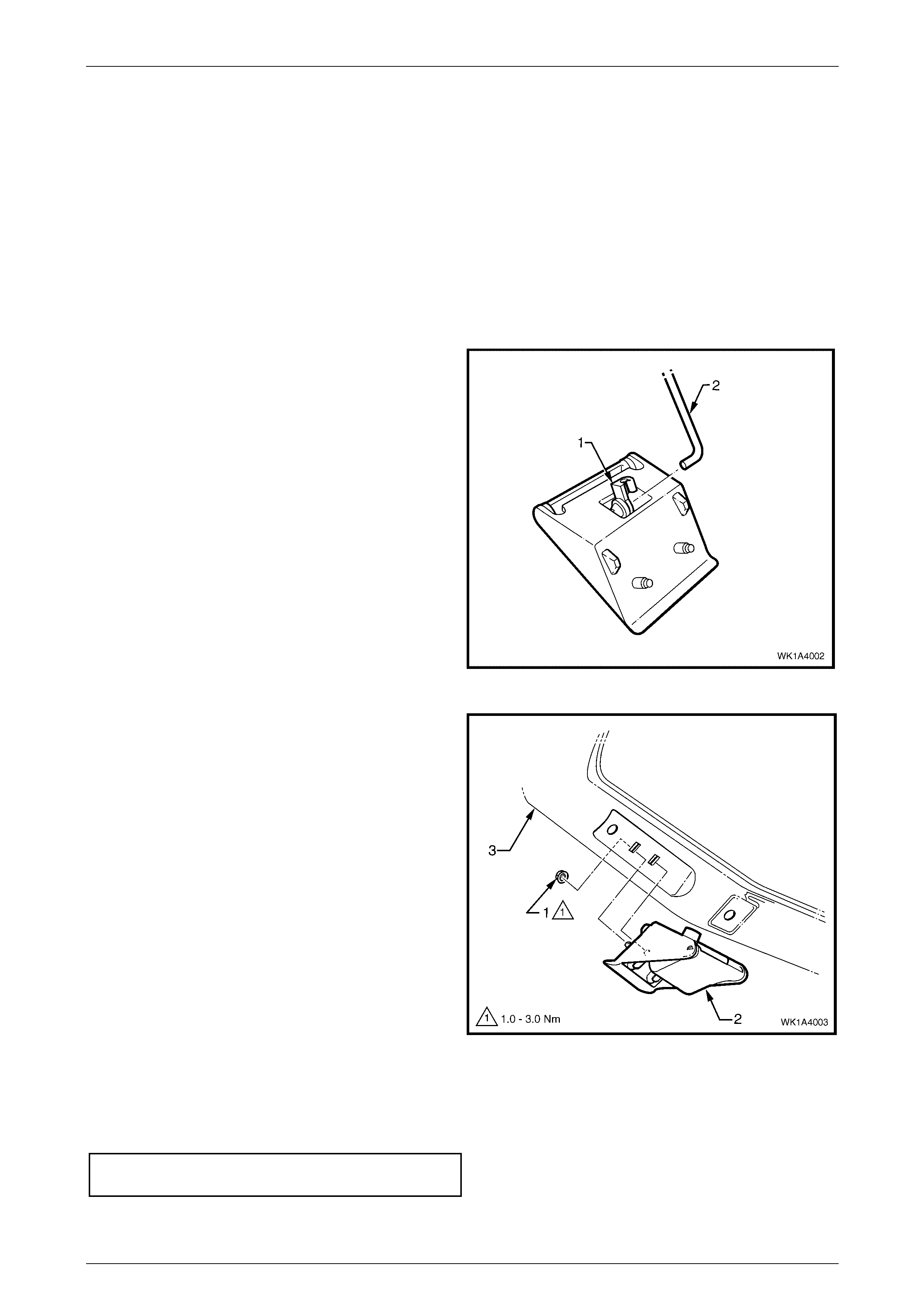
5 Remove the nut (1), two places, attaching the hood
secondary lock lever (2) to the hood (3), and remove
the lever.
Figure 1A4 – 2
Reinstall
1 Reinstallation is the reverse of removal. Tighten the hood secondary lock lever nuts to the specified torque.
Hood secondary lock lever attaching nut
torque specification....................................1.0 – 3.0 Nm
Hood, Rear Com part ment Lid, Li f tgate & Endgate Page 1A4–4
Page 1A4–4
2.2 Hood Secondary Latch Assembly
LT Section No. – 12-050
NOTE
The following component WILL REQUIRE
REPLACEMENT when performing this operation.
• Secondary Latch Rivet
Remove
1 Raise the hood.
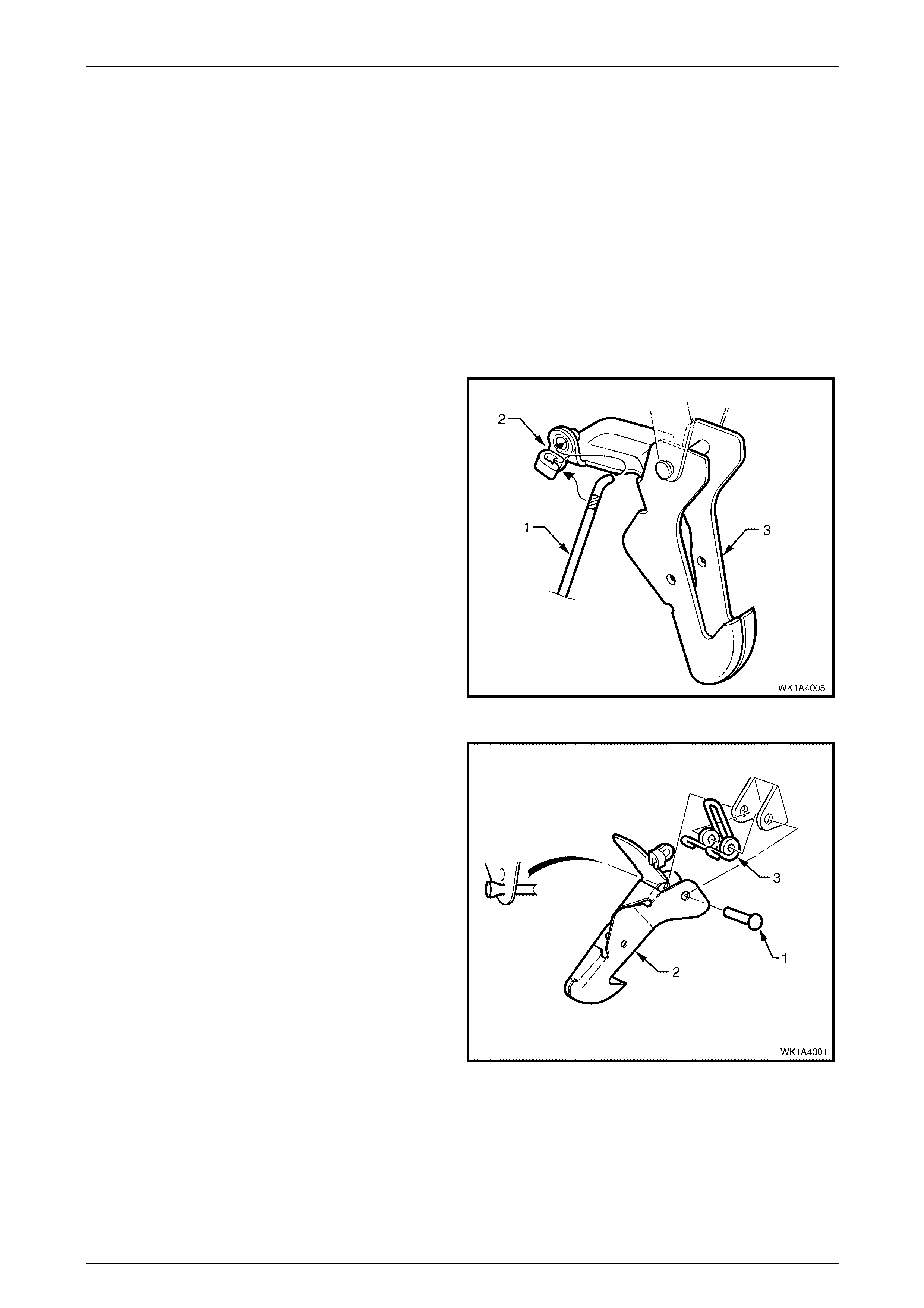
2 Unclip the rod (1) from the retainer (2) attaching it to
the hood secondary latch assembly (3).
3 Remove the rod from the assembly.
Figure 1A4 – 3
4 Carefully cut the end of the secondary latch rivet (1)
that is securing the hood secondary latch (2) and
hood secondary latch spring (3) to the hood assembly.
5 Using a pin punch, extract the rivet, also removing the
latch and spring.
NOTE
Take care not to damage the paintwork.
Figure 1A4 – 4

Hood, Rear Com part ment Lid, Li f tgate & Endgate Page 1A4–5
Page 1A4–5
Reinstall
1 Assemble the spring in the latch ensuring it is correctly orientated.
NOTE
Lubricate the rivet prior to assembly with NLGI
No. 1 lithium grease or equivalent.
2 While holding the latch and spring in position on the hood, insert a new rivet and crimp the end to secure it.
3 Place the rod into position and attach it with the retainer.
4 Test the secondary latch operation.
Hood, Rear Com part ment Lid, Li f tgate & Endgate Page 1A4–6
Page 1A4–6
3 Service Operations – Rear
Compartment Lid
3.1 Rear Compartment Lid Safety Triangle
LT Section No. – 14-480
Remove
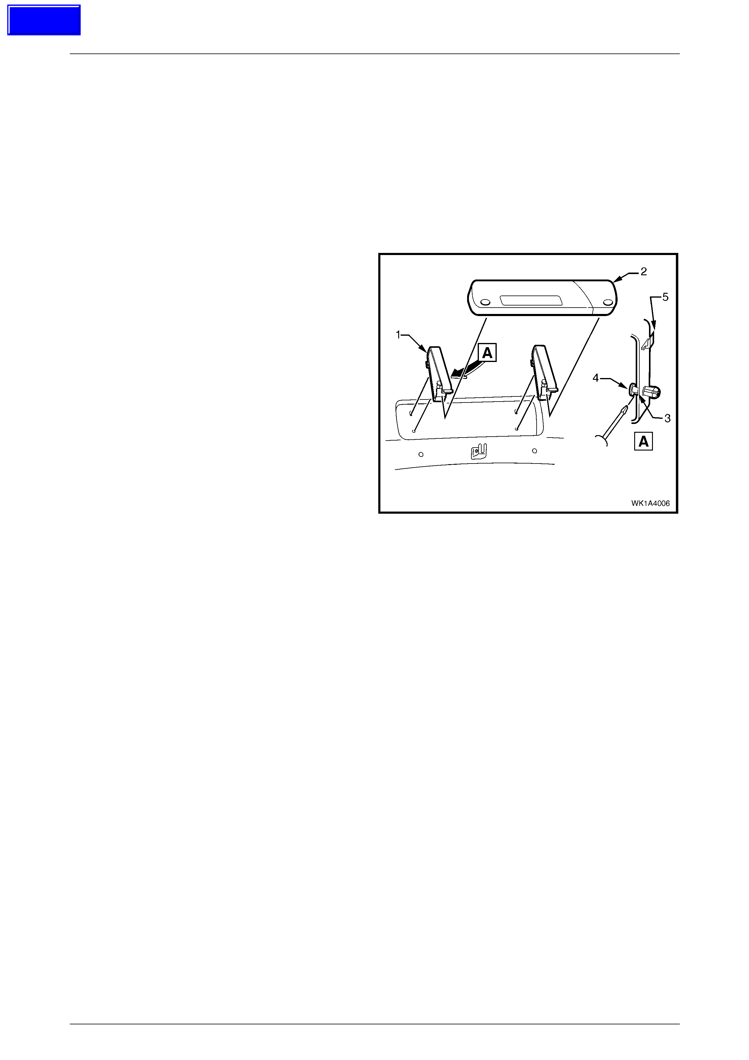
1 Unfasten the safety triangle retainers (1) and remove
the safety triangle (2).
2 Insert a fine flat-bladed screwdriver in the slot (3)
under the pin head (4) and prise the pin out.
3 Withdraw the lower portion of the safety triangle
retainer and then pull it down and out to release the
upper tab (5).
Figure 1A4 – 5
Reinstall
1 Reinstallation is the reverse of removal
Techline
Hood, Rear Com part ment Lid, Li f tgate & Endgate Page 1A4–7
Page 1A4–7
3.2 Rear Compartment Lid Carpet
LT Section No. – 14-480
As required, first remove the rear compartment lid safety triangle, refer to 3.1 Rear Compartment Lid Safety Triangle.
Remove
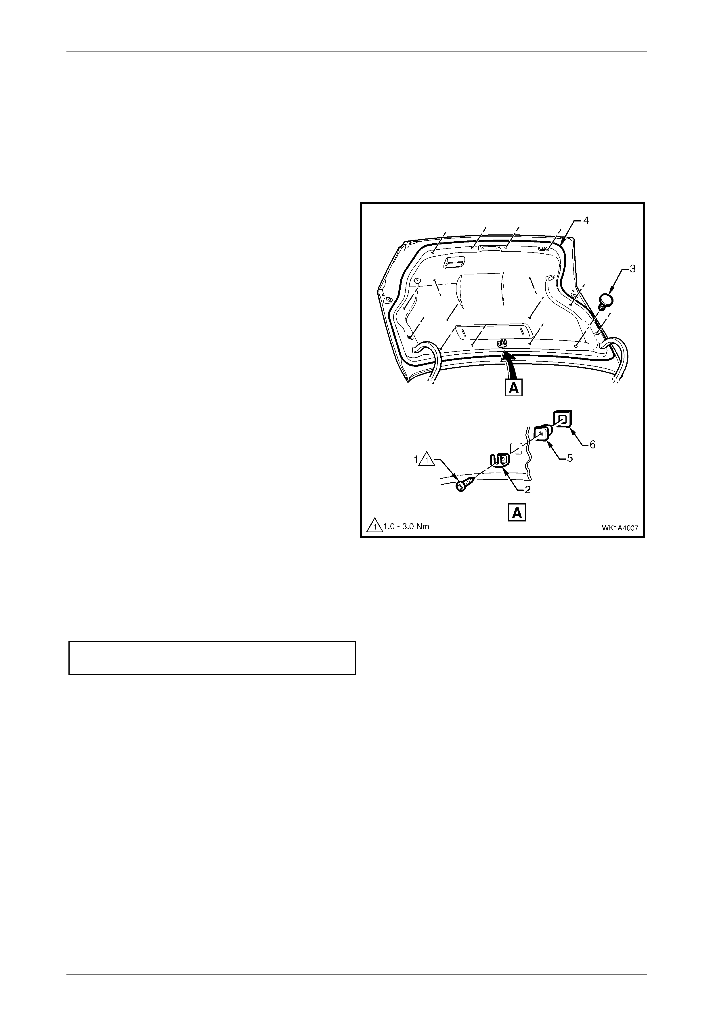
1 Remove the screw (1) attaching the spare wheel
stowage cover hook (2), and remove the hook.
2 Using a suitable trim clip removal tool, remove the
retainers (3) attaching the rear compartment lid carpet
(4) in 16 places.
3 Remove the carpet from the rear compartment lid.
4 If required, prise the nut (5) and washer (6) from the
rear compartment lid with a fine flat-blade screwdriver.
Figure 1A4 – 6
Reinstall
1 Reinstallation is the reverse of removal. Tighten the spare wheel stowage cover hood screw to the specified
torque.
Spare wheel stowage cover hook attaching
screw torque specification..........................1.0 – 3.0 Nm
Hood, Rear Com part ment Lid, Li f tgate & Endgate Page 1A4–8
Page 1A4–8
3.3 Rear Spoiler Assembly
LT Section No. – 10-350
As required, first remove the rear compartment lid carpet, refer to 3.2 Rear Compartment Lid Carpet.
Remove
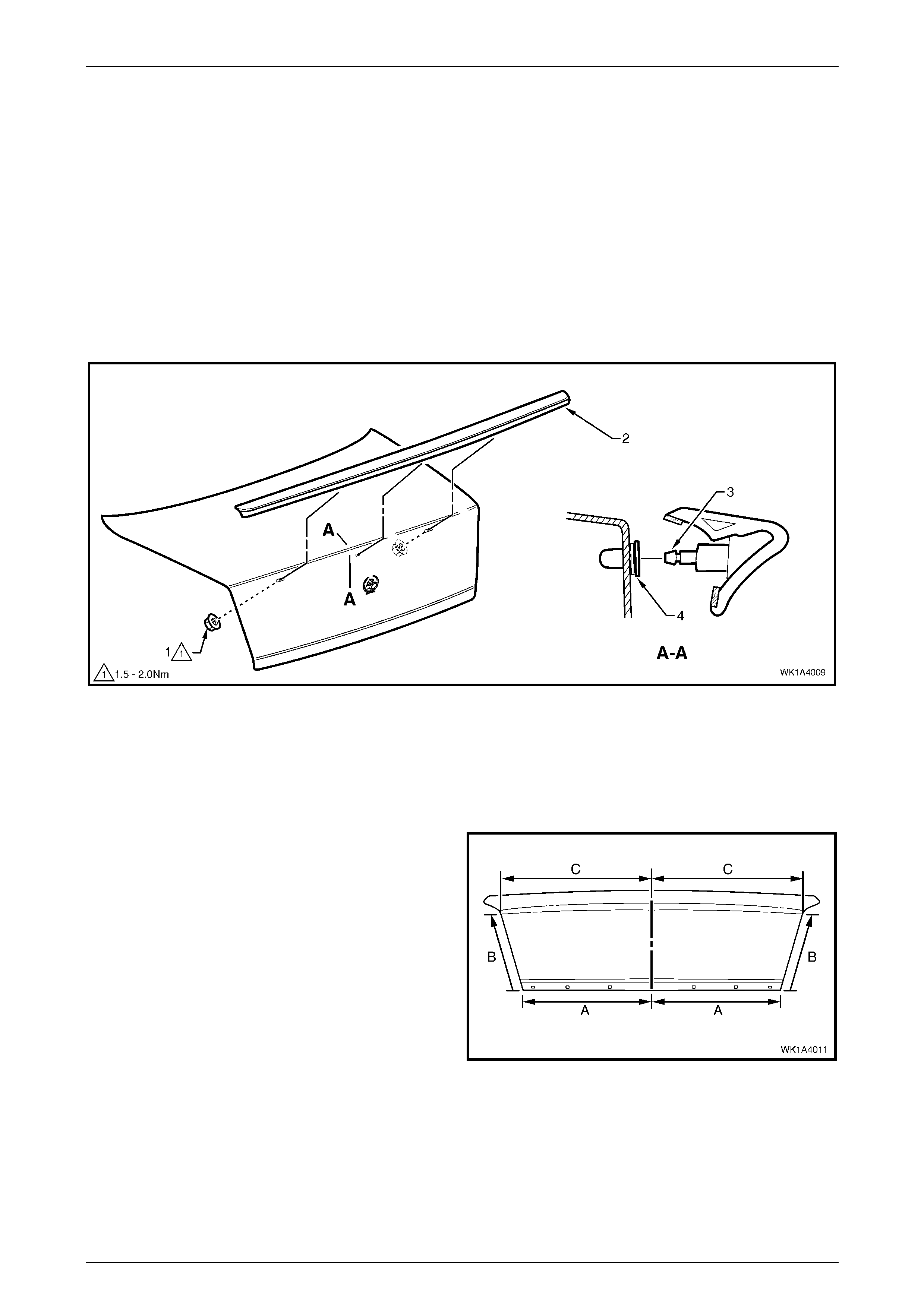
1 Locate the holes from inside the rear compartment lid and remove the nut (1), two places, attaching the spoiler (2)
to the rear compartment lid, refer to Figure 1A4 – 7.
2 Carefully lift the spoiler from the rear compartment lid, uncliping the centre lug (3) from the retainer (4).
3 If required, carefully prise the retainer from the rear compartment lid.
Figure 1A4 – 7
Reinstall
Reinstallation is the reverse of removal noting the following.
1 If the rear compartment lid has not been replaced, proceed to Step 16.
2 Measure along the lower edge of the rear
compartment lid (A) and mark the centre point.
3 Measure up each side of the rear compartment lid
equally (B, approximately 300.0 mm) and mark a
point.
4 Measure across the upper area of the rear
compartment lid (C) from points (B) and mark the
centre point.
5 Draw a vertical centreline between the two centre
points.
Figure 1A4 – 8
Hood, Rear Com part ment Lid, Li f tgate & Endgate Page 1A4–9
Page 1A4–9
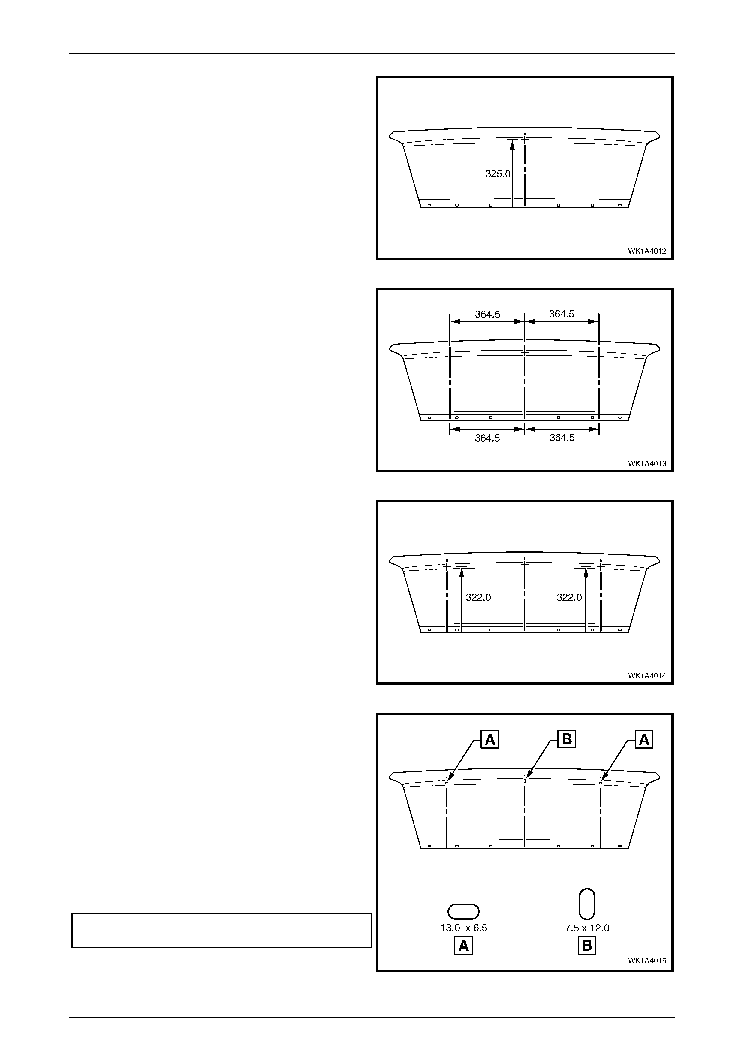
6 Measure up 325.0 mm from the lower edge along the
centreline and mark the centre point of the middle
hole.
Figure 1A4 – 9
7 Measure 364.5 from the centreline at the lower edge
and upper area and mark each point. Repeat for the
opposite side.
8 Draw a vertical line between the marks.
Figure 1A4 – 10
9 Measure up from the lower edge along each vertical
line 322.0 mm and mark the centre point of each outer
hole.
10 Sit the rear spoiler in position and ensure the
attaching studs align with each centre point.
11 Drill a 3.0 mm pilot hole at each centre point.
Figure 1A4 – 11
12 Carefully enlarge the outer holes to a horizontal slot
13.0 x 6.5 mm.
13 Carefully enlarge the inner hole to a vertical slot
7.5 x 12.0 mm.
14 Remove any burrs and drilling swarf from within the
rear compartment lid cavity.
15 Refinish the panel as required.
16 Fit the retainer (4) securely, ensuring the sealing
washer is correctly installed, refer to Figure 1A4 – 7.
17 Tighten the rear spoiler attaching nuts to the specified
torque.
Rear spoiler attaching nut torque
specification ............................................... 1.5 – 2.0 Nm
Figure 1A4 – 12
Hood, Rear Com part ment Lid, Li f tgate & Endgate Page 1A4–10
Page 1A4–10
3.4 Rear Compartment Lid Assembly
LT Section No. – 12-660
As required, first remove the following components:
1 Rear compartment lid safety triangle, refer to 3.1 Rear Compartment Lid Safety Triangle.
2 Rear compartment lid carpet, refer to 3.2 Rear Compartment Lid Carpet.
3 Rear spoiler assembly, if fitted, refer to 3.3 Rear Spoiler Assembly.
4 Rear compartment lid latch assembly, refer to Section 1A4, 3.5 Rear Compartment Lid Latch Assembly in the
MY 2003 VY and V2 Series Service Information.
5 Rear compartment lid actuator assembly, refer to Section 1A4, 3.6 Rear Compartment Lid Actuator Assembly in
the MY 2003 VY and V2 Series Service Information.
6 Rear compartment lid release cable assembly from the rear compartment lid only, refer to Section 1A4, 3.7 Rear
Compartment Lid Release Cable Assembly in the MY 2003 VY and V2 Series Service Information.
7 Badges and emblems, refer to Section 1A9, Exterior Ornamentation.
Remove
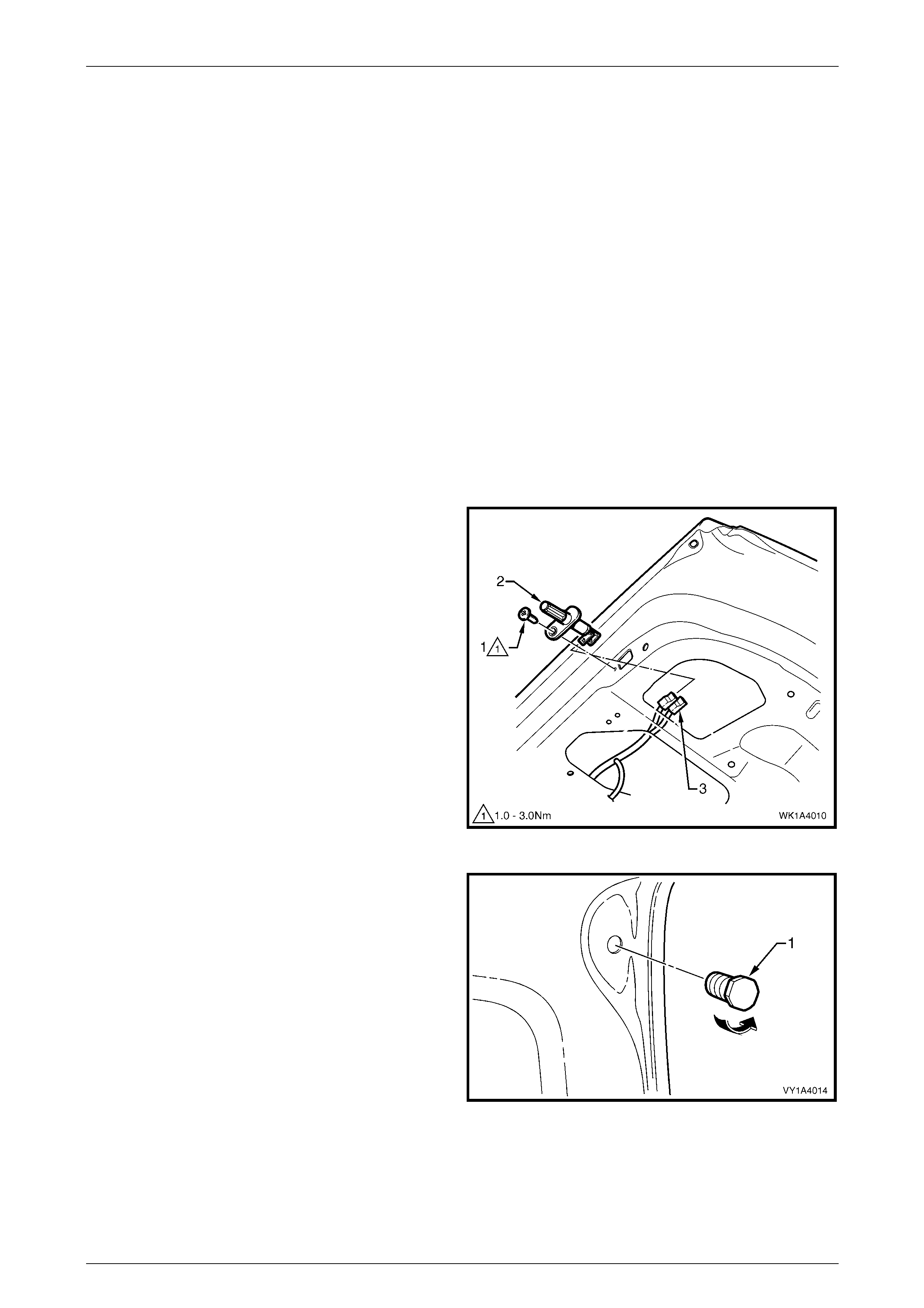
1 Remove the screw (1) attaching the rear compartment
courtesy lamp switch assembly (2) to the rear
compartment lid.
2 Withdraw the switch and disconnect the wiring
connectors (3).
3 Remove the body wiring harness assembly from
the rear compartment lid only. If required, refer to
Section 12O Fuses, Relays And Wiring Harnesses.
Figure 1A4 – 13
4 Unscrew the rear compartment lid bumper (1) from
each side of the rear compartment lid.
Figure 1A4 – 14
Hood, Rear Com part ment Lid, Li f tgate & Endgate Page 1A4–11
Page 1A4–11
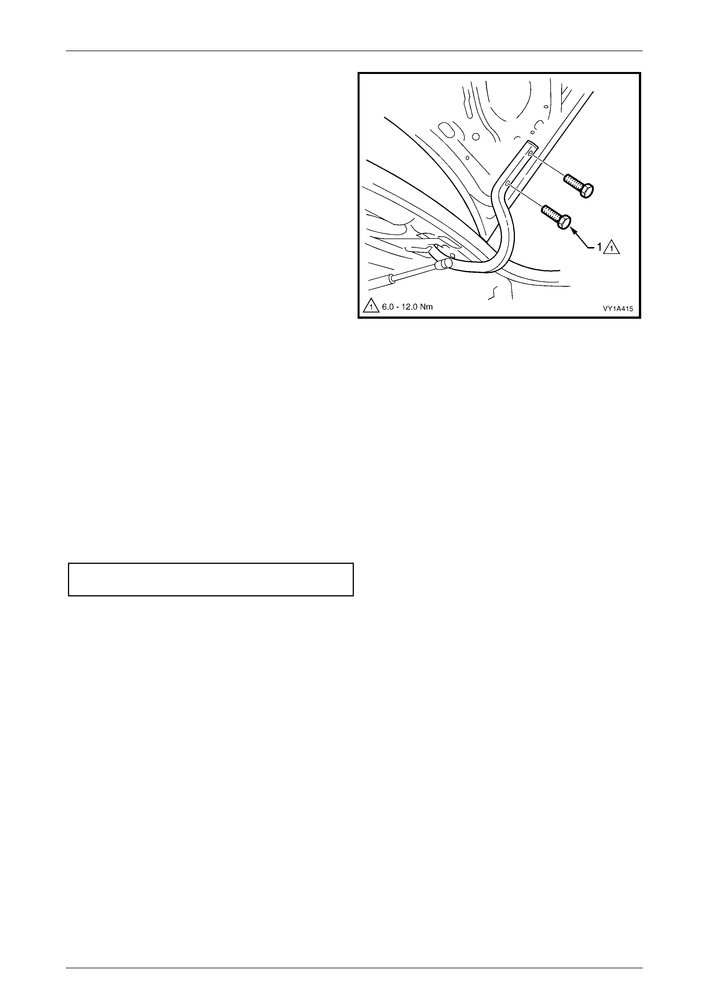
5 Mark the position of the rear compartment lid screws
(1) on the hinges to aid installation.
6 With the aid of an assistant to support the other side
of the rear compartment lid, remove the two screws
each side attaching the rear compartment lid to the
hinges.
7 Carefully lift the rear compartment lid from the vehicle.
Figure 1A4 – 15
Reinstall
1 With the aid of an assistant, lift the rear compartment lid into position.
2 Align the rear compartment lid with the screw holes in the hinges and install the four attaching screws, do not
tighten.
3 Align the screw heads with the marks previously made and temporarily tighten the screws. If no marks exist, align
the screws centrally in their holes.
4 Install the rear compartment lid bumper each side, setting them fully in.
5 Carefully close the rear compartment lid ensuring it does not contact the surrounding panels.
6 If required, adjust the position of the rear compartment lid, refer to the following procedure, Adjust.
7 Tighten the rear compartment lid attaching screws to the specified torque.
Rear compartment lid attaching screw
torque specification..................................6.0 – 12.0 Nm
8 Reinstallation of the remaining components is the reverse of removal.
NOTE
Ensure the body wiring harness assembly
is correctly routed and attached within the rear
compartment lid, refer to Section 12O Fuses,
Relays And Wiring Harnesses.
Adjust
Correct alignment of the rear compartment lid is critical to its operation and to the aesthetics of the vehicle. The
following components allow adjustment of the rear compartment lid:
• Rear compartment lid bumper: Provides vertical adjustment at the rear of the rear compartment lid.
• Rear compartment lid to hinge screws and rear compartment lid hinge to body screws: Provide forward, rearward
and skew adjustment of the rear compartment lid.
• Rear compartment lid striker assembly: Provides vertical and sideways adjustment of the rear compartment lid.
Hood, Rear Com part ment Lid, Li f tgate & Endgate Page 1A4–12
Page 1A4–12
NOTE
Do not make all adjustments at once. Perform
one adjustment, carefully close the hood, check
its position and make further adjustments until
correct alignment is achieved.
If further adjustment is required, loosen the
screws attaching the rear compartment lid hinge
to the body and adjust the position of the hinge,
refer to 3.10 Rear Compartment Hinge Assembly
in the MY 2003 VY and V2 Series Service
Information.
Whenever alignment is required, perform adjustment in the following order.
1 If fitted, remove the rear compartment lid striker assembly, refer to 3.11 Rear Compartment Lid Striker Assembly in
the MY 2003 VY and V2 Series Service Information.
2 Ensure the rear compartment lid weatherstrip assembly is installed and the rear compartment lid bumpers are
fitted and set fully in.
3 Carefully close the rear compartment lid, watching each side does not contact the vehicle.
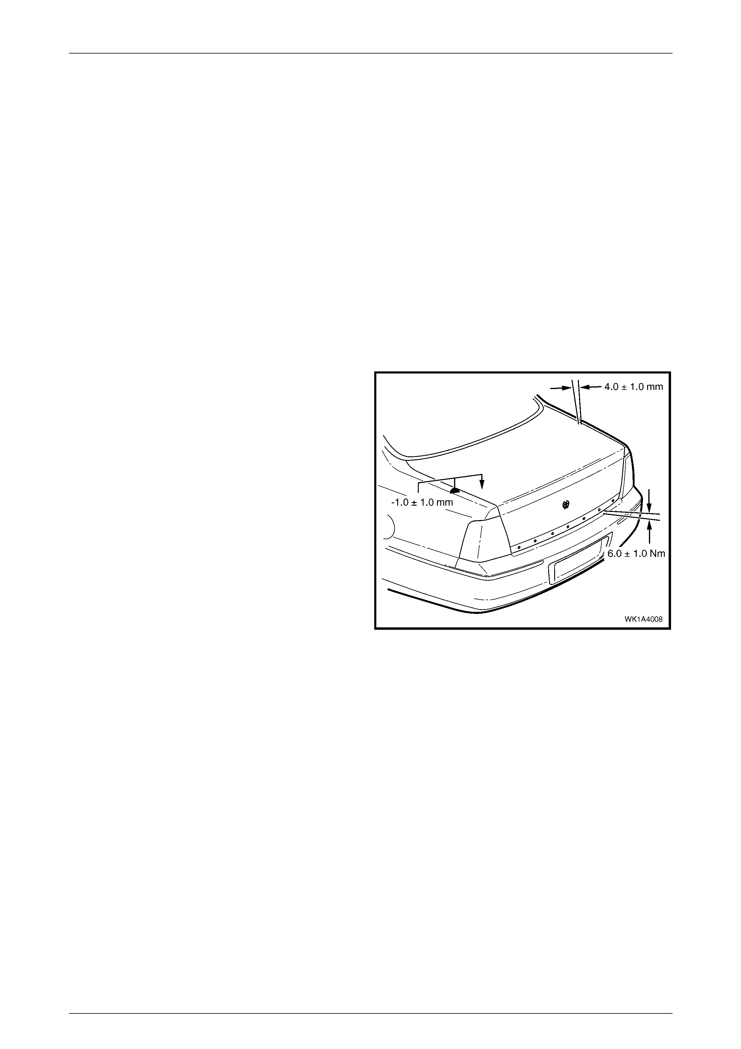
4 Check the alignment of the rear compartment lid for:
• Length. Compare to the tail lamps. They should
be equal.
• Width of gap. Compare the gap between the
rear compartment lid and quarter panel each
side. The gap specification is 4.0 mm ±1.0 mm.
• Consistency of gap. Compare the width of gap
between the rear compartment lid and quarter
panel at the front, middle and rear each side. It
should be even.
5 Open the rear compartment lid and as required,
loosen the screws attaching rear compartment lid to
the hinge assembly for fore, aft and skew adjustment.
6 Install the rear compartment lid striker assembly, refer
to 3.11 Rear Compartment Lid Striker Assembly in the
MY 2003 VY and V2 Series Service Information.
7 Close the rear compartment lid watching that the
striker does not pull the rear compartment lid to one
side changing the panel gaps. If it does, move the
striker as required.
8 Check the height difference between the rear
compartment lid and quarter panel each side. The
specification is -1.0 mm ± 1.0 mm.
9 The rear compartment lid to rear bumper fascia
assembly gap specification is 6.0 mm ± 1.0 mm.
10 As required, open the rear compartment lid, adjust the
striker and/or bumper and recheck.
11 Check that all screws are tightened to their specified
torque, refer to the appropriate procedures.
Figure 1A4 – 16

Hood, Rear Com part ment Lid, Li f tgate & Endgate Page 1A4–13
Page 1A4–13
4 Torque Wrench Specifications
Hood
Hood secondary lock lever attaching nut
torque specification........................................................................1.0 – 3.0 Nm
Rear Compartment Lid
Spare wheel stowage cover hook attaching screw........................1.0 – 3.0 Nm
Rear spoiler attaching nut..............................................................1.5 – 2.0 Nm
Rear compartment lid assembly attaching screw........................6.0 – 12.0 Nm