
Seat Assemblies Page 1A7–1
Page 1A7–1
Section 1A7
Seat Assemblies
ATTENTION
Before performing any Service Operation or other procedure described in this Section, refer to Section 00
Warnings, Cautions and Notes for correct workshop practices with regard to safety and/or property damage.
1 General Information............................................................................................................................. 12
1.1 Front Seat General Description...........................................................................................................................12
Seat Covers...........................................................................................................................................................13
Electric Seat Operation........................................................................................................................................13
Raise/Lower Movement....................................................................................................................................13
Fore/Aft Movement...........................................................................................................................................14
Recline Movement............................................................................................................................................14
Four-way and Six-way Movement Control........................................................................................................14
Eight-way Movement Control............................................................................................................................14
Memory Seat Position System..........................................................................................................................15
Priority Keys (Level 5 Vehicles Only)................................................................................................................15
Memory Buttons................................................................................................................................................15
Using the Exterior Mirrors.................................................................................................................................16
Active Head Restraints........................................................................................................................................17
1.2 Rear Seat General Description............................................................................................................................18
Seat Covers...........................................................................................................................................................18
Surebond..........................................................................................................................................................18
Hook and loop ..................................................................................................................................................18
Conventional pul l-dow n ....................................................................................................................................18
2 Service Operations – Front Seat, Level 1 and 3 ............................................................................... 19
2.1 Front Seat Usage Chart .......................................................................................................................................19
How To Use This Chart........................................................................................................................................19
Gulf States........................................................................................................................................................19
Front Seat Type 1.................................................................................................................................................20
Front Seat Type 2.................................................................................................................................................21
Front Seat Type 3.................................................................................................................................................22
Front Seat Type 4.................................................................................................................................................23
Front Seat Type 5.................................................................................................................................................24
Front Seat Type 6.................................................................................................................................................26
2.2 Fire Extinguisher Assembly................................................................................................................................28
Remove .................................................................................................................................................................28
Reinstall ................................................................................................................................................................28
2.3 Front Seat Assembly............................................................................................................................................29
Remove .................................................................................................................................................................29
Reinstall ................................................................................................................................................................31
2.4 Front Seat Outer Side Cover Assembly..............................................................................................................32
Remove .................................................................................................................................................................32
Disassemble .........................................................................................................................................................33
Front Seat Adjustment Switch, Front Seat Type 1 and 2..................................................................................33
Front Seat Adjustment Switch, Front Seat Type 3 – 6......................................................................................33
Reinstall ................................................................................................................................................................34
2.5 Front Seat Inner Side Cover................................................................................................................................35
Remove .................................................................................................................................................................35
Reinstall ................................................................................................................................................................35
Techline
Techline
Techline
Techline
Techline

Seat Assemblies Page 1A7–2
Page 1A7–2
2.6 Front Seat-back Rear Cover Assembly and Lumbar Support Knob Assembly..............................................36
Disassemble .........................................................................................................................................................37
Lumbar Support Knob and Deflector Ring........................................................................................................37
Front Seat-back Map Pocket............................................................................................................................38
Reinstall ................................................................................................................................................................39
2.7 Front Seat Head Restraint Assembly .................................................................................................................41
Remove .................................................................................................................................................................41
Disassemble .........................................................................................................................................................42
Reassemble ..........................................................................................................................................................42
Reinstall ................................................................................................................................................................42
2.8 Front Seat Head Restraint Sleeve.......................................................................................................................43
Remove .................................................................................................................................................................43
Reinstall ................................................................................................................................................................43
2.9 Front Seat-back Pad and Cover Assembly ........................................................................................................44
Remove .................................................................................................................................................................44
Disassemble .........................................................................................................................................................45
Reassemble ..........................................................................................................................................................46
Reinstall ................................................................................................................................................................46
2.10 Front Seat-back Frame Assembly.......................................................................................................................47
Remove .................................................................................................................................................................47
Disassemble .........................................................................................................................................................48
Lumbar Support and Adjuster Assembly..........................................................................................................48
Side Impact Airbag Assembly...........................................................................................................................50
Front Seat Dummy Block Insert Assembly .......................................................................................................51
Reinstall ................................................................................................................................................................52
2.11 Track and Height Adjust Assembly....................................................................................................................53
Remove .................................................................................................................................................................53
Reinstall ................................................................................................................................................................54
2.12 Front Seat Cushion Pad and Cover Assembly ..................................................................................................55
Remove .................................................................................................................................................................55
Disassemble .........................................................................................................................................................56
Reassemble ..........................................................................................................................................................57
Reinstall ................................................................................................................................................................58
2.13 Front Seat Cushion Frame Assembly.................................................................................................................59
Remove .................................................................................................................................................................59
Disassemble .........................................................................................................................................................59
Reassemble ..........................................................................................................................................................59
Reinstall ................................................................................................................................................................59
2.14 Front Seat Lift Motor Assemblies.......................................................................................................................60
2.15 Front Seat Fore/Aft Movement Motor Assembly ...............................................................................................61
2.16 Front Seat-back Recline Motor Assembly..........................................................................................................62
3 Diagnostics – Front Seat, Level 1 and 3............................................................................................ 63
3.1 Prerequisites.........................................................................................................................................................63
Safety Requirements............................................................................................................................................63
Equipment.............................................................................................................................................................63
Testing Procedures..............................................................................................................................................63
3.2 Mechanical Diagnosis..........................................................................................................................................64
Lumbar Support Inoperative ...............................................................................................................................64
Introduction.......................................................................................................................................................64
Test Description................................................................................................................................................64
Four-way/Six-wa y Seat-back Recline Forward and/or Aft Function is Inoperative ........................................65
Introduction.......................................................................................................................................................65
Test Description................................................................................................................................................65
Four-way Seat Fore/Aft Movement Function is Inoperative or is Not Smooth................................................65
Introduction.......................................................................................................................................................65
Test Description................................................................................................................................................65

Seat Assemblies Page 1A7–3
Page 1A7–3
3.3 Electrical Diagnosis – Four-way/Six-way Seat...................................................................................................66
Wiring Diagram – Four-way/Six-way Seat..........................................................................................................67
Connector Chart – Four-way/Six-way Seat ........................................................................................................68
Neither Seat Adjustment Switch Functions Operate.........................................................................................69
Introduction.......................................................................................................................................................69
Test Description................................................................................................................................................69
None of the Driver’s Seat Adjustment Switch Functions Operate...................................................................71
Introduction.......................................................................................................................................................71
Test Description................................................................................................................................................71
Front/Rear of the Driver's Seat Does Not Raise and/or Lower.........................................................................72
Introduction.......................................................................................................................................................72
Test Description................................................................................................................................................72
Driver’s Seat Fore/Aft Movement Function is Inoperative or not Smooth.......................................................74
Introduction.......................................................................................................................................................74
Test Description................................................................................................................................................74
None of the Passenger's Seat Adjustment Switch Functions Operate ...........................................................76
Introduction.......................................................................................................................................................76
Test Description................................................................................................................................................76
Front/Rear of the Passenger's Seat Does Not Raise and/or Lower .................................................................78
Introduction.......................................................................................................................................................78
Test Description................................................................................................................................................78
3.4 Four-way Seat Adjustment Switch Test.............................................................................................................80
Test........................................................................................................................................................................80
3.5 Six-way Seat Adjustment Switch Test................................................................................................................81
Test........................................................................................................................................................................81
3.6 Electrical Diagnosis – Eight-way Seat................................................................................................................82
Wiring Diagram – Eight-way Seat .......................................................................................................................83
Connector Chart – Eight-way Seat......................................................................................................................84
Neither Seat Adjustment Switch Functions Operate.........................................................................................85
Introduction.......................................................................................................................................................85
Test Description................................................................................................................................................85
None of the Driver’s Seat Adjustment Switch Functions Operate...................................................................87
Introduction.......................................................................................................................................................87
Test Description................................................................................................................................................87
Front/Rear of the Driver’s Seat Does Not Raise and/or Lower.........................................................................89
Introduction.......................................................................................................................................................89
Test Description................................................................................................................................................89
Driver’s Seat Fore/Aft Movement Function is Inoperative or Not Smooth......................................................91
Introduction.......................................................................................................................................................91
Test Description................................................................................................................................................91
Driver’s Seat-back Recline Forward and/or Aft Function is Inoperative .........................................................93
Introduction.......................................................................................................................................................93
Test Description................................................................................................................................................93
None of the Passenger’s Seat Adjustment Switch Functions Operate...........................................................94
Introduction.......................................................................................................................................................94
Test Description................................................................................................................................................94
Front/Rear of the Passenger’s Seat Does Not Raise and/or Lower.................................................................96
Introduction.......................................................................................................................................................96
Test Description................................................................................................................................................96
Passenger’s Seat Fore/Aft Movement Function is Inoperative or Not Smooth ..............................................98
Introduction.......................................................................................................................................................98
Test Description................................................................................................................................................98
Passenger’s Seat-back Recline Forward and/or Aft Function is Inoperative................................................100
Introduction.....................................................................................................................................................100
Test Description..............................................................................................................................................100
3.7 Eight- way Seat Adjustment Switch Test ..........................................................................................................101
Test......................................................................................................................................................................101

Seat Assemblies Page 1A7–4
Page 1A7–4
4 Service Operations – Front Seat, Level 2, 4 and 5 ......................................................................... 102
4.1 Front Seat Usage Chart .....................................................................................................................................102
How To Use This Chart......................................................................................................................................102
Domestic.........................................................................................................................................................102
Gulf States......................................................................................................................................................103
Front Seat Type 7...............................................................................................................................................104
Front Seat Type 8...............................................................................................................................................106
Front Seat Type 9...............................................................................................................................................108
Front Seat Type 10.............................................................................................................................................110
Front Seat Type 11.............................................................................................................................................112
Front Seat Type 12.............................................................................................................................................114
Front Seat Type 13.............................................................................................................................................116
Front Seat Type 14.............................................................................................................................................118
Front Seat Type 11 – 14 Head Restraint Assembly.........................................................................................129
4.2 Fire Extinguisher Assembly..............................................................................................................................130
Remove ...............................................................................................................................................................130
Reinstall ..............................................................................................................................................................130
4.3 Front Seat Assembly..........................................................................................................................................131
Remove ...............................................................................................................................................................131
Reinstall ..............................................................................................................................................................133
Seat Memory Calibration, Front Seat Type 11 and 13.....................................................................................134
4.4 Front Seat Outer Side Cover Assembly............................................................................................................136
Remove ...............................................................................................................................................................136
Disassemble .......................................................................................................................................................137
Front Seat Adjustment Switch ........................................................................................................................137
Memory Position Switch Assembly.................................................................................................................138
Reinstall ..............................................................................................................................................................138
4.5 Front Seat Inner Side Cover..............................................................................................................................138
Remove ...............................................................................................................................................................139
Reinstall ..............................................................................................................................................................139
4.6 Front Seat-back Rear Cover Assembly ............................................................................................................140
Remove ...............................................................................................................................................................140
Disassemble .......................................................................................................................................................141
Reassemble ........................................................................................................................................................141
Reinstall ..............................................................................................................................................................141
4.7 Front Seat Head Restraint Assembly ...............................................................................................................143
Front Seat Type 7 – 10 .......................................................................................................................................143
Remove..........................................................................................................................................................143
Disassemble...................................................................................................................................................143
Reassemble....................................................................................................................................................143
Reinstall..........................................................................................................................................................143
Front Seat Type 11 – 14 .....................................................................................................................................144
Remove..........................................................................................................................................................144
Disassemble...................................................................................................................................................145
Reassemble....................................................................................................................................................148
Reinstall..........................................................................................................................................................148
4.8 Front Seat Head Restraint Sleeve.....................................................................................................................149
Front Seat Type 7 – 10 .......................................................................................................................................149
Remove..........................................................................................................................................................149
Reinstall..........................................................................................................................................................149
Front Seat Type 11 – 14 .....................................................................................................................................150
Remove..........................................................................................................................................................150
Reinstall..........................................................................................................................................................151
4.9 Lumbar Support Knob Assembly .....................................................................................................................152
Remove ...............................................................................................................................................................152
Reinstall ..............................................................................................................................................................152

Seat Assemblies Page 1A7–5
Page 1A7–5
4.10 Front Seat-back Pad and Cover Assembly ......................................................................................................153
Remove ...............................................................................................................................................................153
Disassemble .......................................................................................................................................................154
Reassemble ........................................................................................................................................................155
Reinstall ..............................................................................................................................................................155
4.11 Front Seat-back Frame Assembly .....................................................................................................................156
Remove ...............................................................................................................................................................156
Disassemble .......................................................................................................................................................157
Side Impact Airbag Assembly.........................................................................................................................157
Front Seat Dummy Block Insert Assembly .....................................................................................................158
Lumbar Support Assembly .............................................................................................................................158
Active Head Restraint Frame Assembly.........................................................................................................160
Reinstall ..............................................................................................................................................................161
4.12 Seat Memory Module .........................................................................................................................................162
Remove ...............................................................................................................................................................162
Reinstall ..............................................................................................................................................................162
4.13 Track and Height Adjust Assembly..................................................................................................................163
Remove ...............................................................................................................................................................163
Reinstall ..............................................................................................................................................................164
4.14 Front Seat Cushion Pad and Cover Assembl y ................................................................................................165
Remove ...............................................................................................................................................................165
Disassemble .......................................................................................................................................................165
Reassemble ........................................................................................................................................................166
Reinstall ..............................................................................................................................................................167
4.15 Front Seat Cushion Frame Assembly...............................................................................................................168
Remove ...............................................................................................................................................................168
Disassemble .......................................................................................................................................................168
Reassemble ........................................................................................................................................................168
Reinstall ..............................................................................................................................................................168
4.16 Front Seat Lift Motor Assemblies .....................................................................................................................169
4.17 Front Seat Fore/Aft Movement Motor Assembly .............................................................................................170
4.18 Front Seat-back Recline Motor Assembly........................................................................................................171
4.19 Drive Motor Potentiometers ..............................................................................................................................172
5 Diagnostics – Front Seat, Level 2, 4 and 5...................................................................................... 173
5.1 Prerequisites.......................................................................................................................................................173
Safety Requirements..........................................................................................................................................173
Equipment...........................................................................................................................................................173
Testing Procedures............................................................................................................................................173
5.2 Mechanical Diagnosis........................................................................................................................................174
Lumbar Support Inoperative .............................................................................................................................174
Introduction.....................................................................................................................................................174
Test Description..............................................................................................................................................174
5.3 Electrical Diagnosis – Eight-way Seat, Non-memory, RH D............................................................................175
Wiring Diagram – Eight-w ay Seat, Non-memory, RHD....................................................................................176
Connector Chart – Eight-way Seat, Non-memory, RHD..................................................................................177
Neither Seat Ad justment Switch Functions Operate.......................................................................................178
Introduction.....................................................................................................................................................178
Test Description..............................................................................................................................................178
None of the Driver’s Seat Adjustment Switch Functions Operate.................................................................180
Introduction.....................................................................................................................................................180
Test Description..............................................................................................................................................180
Front/Rear of the Driver’s Seat Does Not Raise and/or Lower.......................................................................182
Introduction.....................................................................................................................................................182
Test Description..............................................................................................................................................182
Driver’s Seat Fore/Aft Movement Function is Inoperative or Not Smooth....................................................184
Introduction.....................................................................................................................................................184
Test Description..............................................................................................................................................184

Seat Assemblies Page 1A7–6
Page 1A7–6
Driver’s Seat-back Recline Forward and/or Aft Function is Inoperative .......................................................186
Introduction.....................................................................................................................................................186
Test Description..............................................................................................................................................186
None of the Passenger’s Seat Adjustment Switch Functions Operate .........................................................187
Introduction.....................................................................................................................................................187
Test Description..............................................................................................................................................187
Front/Rear of the Passenger’s Seat Does Not Raise and/or Lower...............................................................189
Introduction.....................................................................................................................................................189
Test Description..............................................................................................................................................189
Passenger’s Seat Fore/Aft Movement Function is Inoperative or Not Smooth ............................................191
Introduction.....................................................................................................................................................191
Test Description..............................................................................................................................................191
Passenger’s Seat-back Recline Forward and/or Aft Function is Inoperative................................................193
Introduction.....................................................................................................................................................193
Test Description..............................................................................................................................................193
5.4 Electrical Diagnosis – Eight-way Seat, Non-memory, LHD .............................................................................194
Wiring Diagram – Eight-way Seat, Non-memory, LHD....................................................................................195
Connector Chart – Eight-way Seat, Non-memory, LHD ..................................................................................196
Neither Seat Ad justment Switch Functions Operate.......................................................................................197
Introduction.....................................................................................................................................................197
Test Description..............................................................................................................................................197
None of the Driver’s Seat Adjustment Switch Functions Operate.................................................................199
Introduction.....................................................................................................................................................199
Test Description..............................................................................................................................................199
Front/Rear of the Driver’s Seat Does Not Raise and/or Lower.......................................................................201
Introduction.....................................................................................................................................................201
Test Description..............................................................................................................................................201
Driver’s Seat Fore/Aft Movement Function is Inoperative or Not Smooth....................................................203
Introduction.....................................................................................................................................................203
Test Description..............................................................................................................................................203
Driver’s Seat-back Recline Forward and/or Aft Function is Inoperative .......................................................205
Introduction.....................................................................................................................................................205
Test Description..............................................................................................................................................205
None of the Passenger’s Seat Adjustment Switch Functions Operate .........................................................206
Introduction.....................................................................................................................................................206
Test Description..............................................................................................................................................206
Front/Rear of the Passenger’s Seat Does Not Raise and/or Lower...............................................................208
Introduction.....................................................................................................................................................208
Test Description..............................................................................................................................................208
Passenger’s Seat Fore/Aft Movement Function is Inoperative or Not Smooth ............................................210
Introduction.....................................................................................................................................................210
Test Description..............................................................................................................................................210
Passenger’s Seat-back Recline Forward and/or Aft Function is Inoperative................................................212
Introduction.....................................................................................................................................................212
Test Description..............................................................................................................................................212
5.5 Eight- way Seat Adjustment Switch Test ..........................................................................................................213
Test......................................................................................................................................................................213
6 Diagnostics – Front Seat Memory and Rear View Mirror, Level 5 ................................................ 214
6.1 Prerequisites.......................................................................................................................................................214
Safety Requirements..........................................................................................................................................214
Equipment...........................................................................................................................................................214
Testing Procedures............................................................................................................................................214
6.2 System Self Diagnosis.......................................................................................................................................215
Current DTCs......................................................................................................................................................215
History DTCs.......................................................................................................................................................215
Clearing DTCs.....................................................................................................................................................215

Seat Assemblies Page 1A7–7
Page 1A7–7
6.3 TECH 2 Diagnostics...........................................................................................................................................216
Test Modes..........................................................................................................................................................216
Mode F0: Diagnostic Trouble Codes..............................................................................................................216
Mode F1: Diagnostic Data Display..................................................................................................................216
Mode F2: Snapshot ........................................................................................................................................216
Mode F3: Miscellaneous Tests.......................................................................................................................216
Mode F4: Additi onal Functions.......................................................................................................................216
6.4 TECH 2 Test Modes and Displays for Diagnosis.............................................................................................217
System Select Menu...........................................................................................................................................217
Body Application Menu......................................................................................................................................217
System Identification .........................................................................................................................................218
Application Menu ...............................................................................................................................................218
F0: Diagnostic Trouble Codes...........................................................................................................................219
F0: Read DTC Information..............................................................................................................................219
F1: Clear DTC Information..............................................................................................................................219
Diagnostic Trouble Codes.................................................................................................................................220
F1: Diagnostic Da ta Displa y..............................................................................................................................220
F0: Inputs and Outputs...................................................................................................................................220
F1: Memory ....................................................................................................................................................224
F2: System Identification ................................................................................................................................226
F2: Snapshot.......................................................................................................................................................226
F3: Miscellaneous Tests....................................................................................................................................226
F0: Chime.......................................................................................................................................................226
F1: LED ..........................................................................................................................................................226
F2: Right Exterior Mirror .................................................................................................................................226
F3: Left Exterior Mirror....................................................................................................................................226
F4: Front Vertical Motor..................................................................................................................................226
F5: Rear vertical Mirror...................................................................................................................................226
F6: Horizontal Motor.......................................................................................................................................226
F7: Recline Motor ...........................................................................................................................................227
F4: Additional Functions ...................................................................................................................................227
F0: Module Reset ...........................................................................................................................................227
6.5 Preliminary S ystem Diagnosis..........................................................................................................................228
6.6 Diagnostic Charts...............................................................................................................................................229
Introduction ........................................................................................................................................................229
6.7 Mechanical Diagnosis........................................................................................................................................230
6.8 Electrical Diagnosis – Memory Seat.................................................................................................................231
Wiring Diagram – RHD.......................................................................................................................................231
Wiring Diagram – LHD .......................................................................................................................................233
Connector Chart.................................................................................................................................................235
Initial Check........................................................................................................................................................236
Circuit Description...........................................................................................................................................236
Test Description..............................................................................................................................................236
No Serial Data Communications to the Seat Memory Module........................................................................242
Circuit Description...........................................................................................................................................242
Test Description..............................................................................................................................................242
Notes on the Diagnostic Chart........................................................................................................................242
Seat Adjustment Switch Assembly Inoperative – RHD...................................................................................244
Circuit Description...........................................................................................................................................244
Test Description..............................................................................................................................................244
Notes on the Diagnostic Chart........................................................................................................................244
Seat Adjustment Switch Assembly Inoperative – LHD ...................................................................................246
Circuit Description...........................................................................................................................................246
Test Description..............................................................................................................................................246
Notes on the Diagnostic Chart........................................................................................................................246
Seat Front Lift Motor Inoperative......................................................................................................................248
Circuit Description...........................................................................................................................................248
Test Description..............................................................................................................................................248
Notes on the Diagnostic Chart........................................................................................................................248

Seat Assemblies Page 1A7–8
Page 1A7–8
Seat Rear Lift Motor Inoperative .......................................................................................................................249
Circuit Description...........................................................................................................................................249
Test Description..............................................................................................................................................249
Notes on the Diagnostic Chart........................................................................................................................249
Seat Fore / Aft Movement Motor Inoperative ...................................................................................................250
Circuit Description...........................................................................................................................................250
Test Description..............................................................................................................................................250
Notes on the Diagnostic Chart........................................................................................................................250
Front Seat-back Recline Motor Inoperative......................................................................................................251
Circuit Description...........................................................................................................................................251
Test Description..............................................................................................................................................251
Notes on the Diagnostic Chart........................................................................................................................251
Memory Position Switch Inoperative – RHD....................................................................................................253
Circuit Description...........................................................................................................................................253
Test Description..............................................................................................................................................253
Notes on the Diagnostic Chart........................................................................................................................253
Memory Position Switch Inoperative – LHD.....................................................................................................255
Circuit Description...........................................................................................................................................255
Test Description..............................................................................................................................................255
Notes on the Diagnostic Chart........................................................................................................................255
Seat Front Lift Motor Potentiometer Check – RHD..........................................................................................257
Circuit Description...........................................................................................................................................257
Test Description..............................................................................................................................................257
Notes on the Diagnostic Chart........................................................................................................................257
Seat Front Lift Motor Potentiometer Check – LHD..........................................................................................259
Circuit Description...........................................................................................................................................259
Test Description..............................................................................................................................................259
Notes on the Diagnostic Chart........................................................................................................................259
Seat Rear Lift Motor Potentiometer Check – RHD...........................................................................................261
Circuit Description...........................................................................................................................................261
Test Description..............................................................................................................................................261
Notes on the Diagnostic Chart........................................................................................................................261
Seat Rear Lift Motor Potentiometer Check – LHD...........................................................................................263
Circuit Description...........................................................................................................................................263
Test Description..............................................................................................................................................263
Notes on the Diagnostic Chart........................................................................................................................263
Seat Fore/Aft Movement Motor Potentiometer Check.....................................................................................265
Circuit Description...........................................................................................................................................265
Test Description..............................................................................................................................................265
Notes on the Diagnostic Chart........................................................................................................................265
Seat-back Recline Motor Potentiometer Check...............................................................................................267
Circuit Description...........................................................................................................................................267
Test Description..............................................................................................................................................267
Notes on the Diagnostic Chart........................................................................................................................267
Priority Key Feature Inoperative .......................................................................................................................269
Circuit Description...........................................................................................................................................269
Test Description..............................................................................................................................................269
Notes on the Diagnostic Chart........................................................................................................................269
DTC 1 — Front Vertical Up Switch Stuck.........................................................................................................270
Right-hand Drive.............................................................................................................................................270
Left-hand Drive...............................................................................................................................................271
DTC 2 — Front Vertical Down Switch Stuck ....................................................................................................272
Right-hand Drive.............................................................................................................................................272
Left-hand Drive...............................................................................................................................................273
DTC 3 — Rear Vertical Up Switch Stuck ..........................................................................................................274
Right-hand Drive.............................................................................................................................................274
Left-hand Drive...............................................................................................................................................275
DTC 4 — Rear Vertical Down Switch Stuck......................................................................................................276
Right-hand Drive.............................................................................................................................................276
Left-hand Drive...............................................................................................................................................277

Seat Assemblies Page 1A7–9
Page 1A7–9
DTC 5 — Horizontal Forward Switch Stuck......................................................................................................278
Circuit Description...........................................................................................................................................278
Test Description..............................................................................................................................................278
Note on Diagnostic Chart................................................................................................................................278
DTC 6 — Horizontal Back Switch Stuck...........................................................................................................279
Circuit Description...........................................................................................................................................279
Test Description..............................................................................................................................................279
Note on Diagnostic Chart................................................................................................................................279
DTC 7 — Recline Up Switch Stuck....................................................................................................................280
Circuit Description...........................................................................................................................................280
Test Description..............................................................................................................................................280
Note on Diagnostic Chart................................................................................................................................280
DTC 8 — Recline Down Switch Stuck...............................................................................................................281
Circuit Description...........................................................................................................................................281
Test Description..............................................................................................................................................281
Note on Diagnostic Chart................................................................................................................................281
DTC 9 — Memory Button 1 Stuck .....................................................................................................................282
Circuit Description...........................................................................................................................................282
Test Description..............................................................................................................................................282
Note on Diagnostic Chart................................................................................................................................282
DTC 10 — Memory Button 2 Stuck ...................................................................................................................283
Circuit Description...........................................................................................................................................283
Test Description..............................................................................................................................................283
Note on Diagnostic Chart................................................................................................................................283
DTC 11 — Memory Button 3 Stuck ...................................................................................................................284
Test Description..............................................................................................................................................284
Note on Diagnostic Chart................................................................................................................................284
DTC 12 — Mirror DIP Button Stuck...................................................................................................................285
Test Description..............................................................................................................................................285
Note on Diagnostic Chart................................................................................................................................285
DTC 13 — No Serial Data...................................................................................................................................286
DTC 14 — No Exterior Mirror Communications...............................................................................................286
DTC 15 — Front Vertical Position Sensor Fault...............................................................................................286
DTC 16 — Rear Vertical Position Sensor Fault................................................................................................286
DTC 17 — Horizontal Position Sensor Fault....................................................................................................286
DTC 18 — Recline Position Sensor Fault.........................................................................................................286
DTC 19 — ECU Malfunction...............................................................................................................................286
6.9 Memory Position Switch Test............................................................................................................................287
Remove ...............................................................................................................................................................287
Reinstall ..............................................................................................................................................................287
Test......................................................................................................................................................................287
6.10 Electrical Diagnosis – Rear-view Mirrors.........................................................................................................289
Wiring Diagram – RHD.......................................................................................................................................289
Wiring Diagram – LHD .......................................................................................................................................290
Connector Chart.................................................................................................................................................291
Initial Check........................................................................................................................................................292
Circuit Description...........................................................................................................................................292
Test Description..............................................................................................................................................292
Notes on the Diagnostic Chart........................................................................................................................292
Mirror Dip Function Check................................................................................................................................295
Circuit Description...........................................................................................................................................295
Test Description..............................................................................................................................................295
Notes on the Diagnostic Chart........................................................................................................................295
Mirror Heating Function Check.........................................................................................................................296
Circuit Description...........................................................................................................................................296
Test Description..............................................................................................................................................296
Notes on the Diagnostic Chart........................................................................................................................296
No Serial Data from Exterior Rear-view Mirrors ..............................................................................................298
Circuit Description...........................................................................................................................................298
Test Description..............................................................................................................................................298
Notes on the Diagnostic Chart........................................................................................................................298

Seat Assemblies Page 1A7–10
Page 1A7–10
No Serial Data – Right-hand Exterior Rear-view Mirror ..................................................................................300
Circuit Description...........................................................................................................................................300
Test Description..............................................................................................................................................300
Notes on the Diagnostic Chart........................................................................................................................300
No Serial Data – Left-hand Exterior Rear-view Mirror.....................................................................................301
Circuit Description...........................................................................................................................................301
Test Description..............................................................................................................................................301
Notes on the Diagnostic Chart........................................................................................................................301
Mirror Control Switch Inoperative.....................................................................................................................302
Circuit Description...........................................................................................................................................302
Test Description..............................................................................................................................................302
Notes on the Diagnostic Chart........................................................................................................................302
7 Service Operations – Rear Seat ....................................................................................................... 304
7.1 Rear Seat Usage Chart.......................................................................................................................................304
How To Use This Chart......................................................................................................................................304
Domestic.........................................................................................................................................................305
Gulf States......................................................................................................................................................305
Rear Seat Type 1 ................................................................................................................................................306
Rear Seat Type 2 ................................................................................................................................................307
Rear Seat Type 3 ................................................................................................................................................309
Rear Seat Type 4 ................................................................................................................................................311
Rear Seat Type 5 ................................................................................................................................................313
Rear Seat Type 6 ................................................................................................................................................315
Rear Seat Type 7 ................................................................................................................................................317
Rear Seat Type 8 ................................................................................................................................................319
Rear Seat-back Centre Tra y and Armrest Assembly w ithout Compartment.................................................321
Rear Seat-back Centre Tray and Armrest Assembly w ith Compartment ......................................................322
7.2 Rear Seat Cushion Assembly............................................................................................................................323
Remove ...............................................................................................................................................................323
Disassemble .......................................................................................................................................................323
Rear Seat Cushion Release Handle...............................................................................................................323
Rear Seat Cushion Frame..............................................................................................................................324
Cushion Cover Assembly..................................................................................................................................329
Rear Seat Type 1............................................................................................................................................329
Rear Seat Type 2 and 5..................................................................................................................................329
Rear Seat Type 3 and 6..................................................................................................................................334
Rear Seat Type 4............................................................................................................................................339
Rear Seat Type 7............................................................................................................................................343
Rear Seat Type 8............................................................................................................................................350
Reinstall ..............................................................................................................................................................355
7.3 Rear Seat-back Head Restraint Assembl y Right and Left-hand Side............................................................356
Remove ...............................................................................................................................................................356
Except Rear Seat Type 4 Head Restraint.......................................................................................................357
Rear Seat Type 4 Head Restraint...................................................................................................................358
Reinstall ..............................................................................................................................................................358
7.4 Rear Seat-back Assembly..................................................................................................................................359
Remove ...............................................................................................................................................................359
Head Restraint Sleeve........................................................................................................................................360
Remove..........................................................................................................................................................360
Reinstall..........................................................................................................................................................360
Rear Seat-back Cover........................................................................................................................................361
Rear Seat Type1.............................................................................................................................................361
Rear Seat Type 2 and 5..................................................................................................................................361
Rear Seat Type 3 and 6..................................................................................................................................368
Rear Seat Type 4............................................................................................................................................374
Rear Seat Type 7 and 8..................................................................................................................................381
Reinstall ..............................................................................................................................................................389

Seat Assemblies Page 1A7–11
Page 1A7–11
7.5 Rear Seat-back Centre Head Restraint Assembly...........................................................................................390
Remove ...............................................................................................................................................................390
Disassemble...................................................................................................................................................391
Reassemble....................................................................................................................................................392
Reinstall ..............................................................................................................................................................392
7.6 Rear Seat-back Centre Armrest Assembly.......................................................................................................393
Remove ...............................................................................................................................................................393
Disassemble Rear Seat Type 1 – 4....................................................................................................................393
Reassemble ........................................................................................................................................................394
Disassemble Rear Seat Type 5 – 8....................................................................................................................395
Rear Seat-back Centre Armrest Hinge...........................................................................................................395
Rear Seat-back Centre Armrest Lid and Cover..............................................................................................396
Rear Seat-back Centre Armrest Deposit Box, Cover and Cup Holder............................................................397
Reassemble ........................................................................................................................................................400
Reinstall ..............................................................................................................................................................400
7.7 Rear Seat-back Centre Assembly.....................................................................................................................401
Remove ...............................................................................................................................................................401
Disassemble .......................................................................................................................................................401
Pad Assembly, Cove r and Head Restraint Sleeves........................................................................................401
Rear Seat-back Centre Release Button..........................................................................................................404
Rear Seat-back Centre Lock Actuator............................................................................................................404
Rear Seat-back Centre Hinge.........................................................................................................................405
Reinstall ..............................................................................................................................................................405
7.8 Rear Seat-back Centre Lock Striker .................................................................................................................406
Remove ...............................................................................................................................................................406
Reinstall ..............................................................................................................................................................406
8 Torque Wrench Specifications......................................................................................................... 407
8.1 Front Seat............................................................................................................................................................407
Level 1 and 3.......................................................................................................................................................407
Level 2, 4 and 5...................................................................................................................................................407
8.2 Rear Seat.............................................................................................................................................................408

Seat Assemblies Page 1A7–12
Page 1A7–12
1 General Information
This Section describes the service and diagnostic procedures for the seat assemblies fitted to MY 2004 WK Series
vehicles and is divided as follows for Service Operations:
• Early type Level 1 and 3 front seat assemblies,
• Level 2, 4 and 5 front seat assemblies and Late type Level 1 and 3,
• Rear seat as semblies,
and Diagnosis:
• Early type Level 1 and 3 front seat assemblies,
• Level 2, 4 and 5 and Late type Level 1 and 3 non-memory front seat assemblies and
• Level 5 memory front seat assemblies.
1.1 Front Seat General Description
For reasons of personal safety, the vehicle
must only be driven after the seat has been
adjusted to the correct driving position. Do
not adjust the driver’s seat when the vehicle
is moving as the seat could move away from
the driving position, causing loss of control.
Accessory and after market seat covers MUST
NOT be fitted to any vehicle with side impact
airbags unless approved b y the manufacturer.
Non-approved seat covers may inhibit the
operation of the side airbag, reducing the
protection otherwise provided to the
occupants during a side-impact collision.
NOTE
Running changes to the front seat assemblies
fitted to Level 1 and 3 vehicles occurred during
production. Front seat assemblies prior to this
change are referred to as "early type" Level 1
and 3.
The front seats fitted to MY 2004 WK Series vehicles are summarised as follows:
• Pressed metal seat-back frame type seat fi tted to early type Level 1 and 3 vehicles,
• Tubular metal seat-back frame type fitted to Level 2, 4 and 5 vehicles and late type Level 1 and 3 vehicles.
The result of these two differences is that components such as the adjustable lumbar support assembly are also different
between seat-back frame types.
Other front seat features fitted depending on vehicle Model Level include:
• Four, six or eight-way electric movement functions,
• Side impact airbag assemblies,
• Standard leather trim for Level 3 and 5 vehicles and optional for Level 2 and 4,
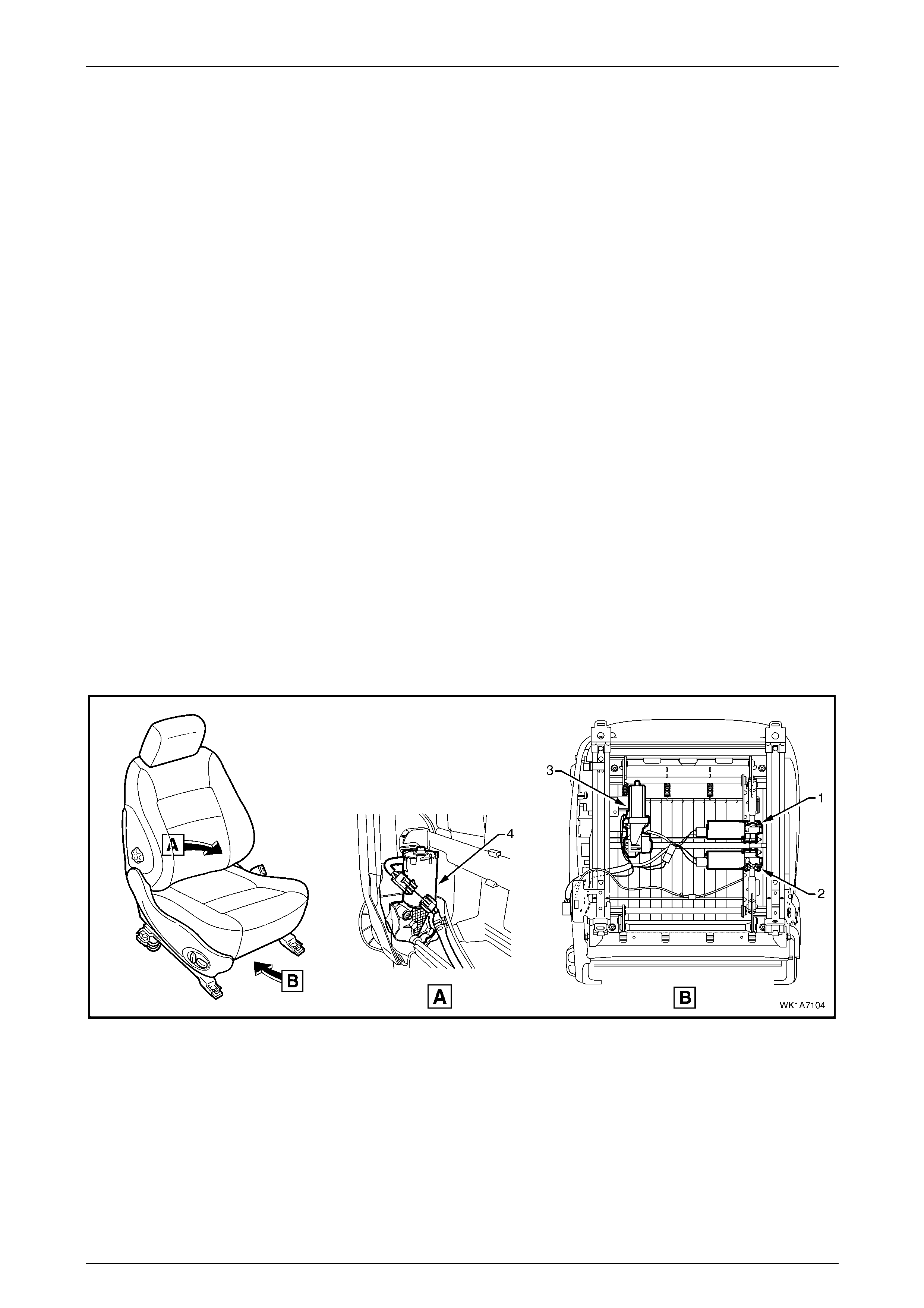
Seat Assemblies Page 1A7–13
Page 1A7–13
• Active head restraints for Level 4 and 5 vehicles,
• Rear seat entertainment screens in the back of the head restraints for Level 5 vehicles , and
• A driver's seat memory position system that integrates with other vehicle functions, also for Level 5 vehicles.
To identify the front seat type fitted, refer to 2.1 Front Seat Usage Chart for early type Level 1 and 3 vehicles, or
4.1 Front Seat Usage Chart for Level 2, 4 and 5 vehicles and late type Level 1 and 3 ve hicles.
The front seatbelt buckle and pretensioner assemblies are attached to the front seats. For service operations refer to
Section 12M, Occupant Protection System.
Seat Covers
Two seat cover construction methods are used for the front seat assemblies. The front seats fitted to Level 1 vehicles
have Surebond type cloth covers. These are not serviced separately as they are glued to the seat pad.
The cloth or leather seat covers fitted to Level 2 – 5 front seat assemblies are fully serviceable as they are attached
within the grooves of the seat pad with a hook and loop system.
Electric Seat Operation
Depending on Model Level of the vehicle, the following front seat electric movement functions are available:
• Four-way – Seat cushion front raise/lower and rear raise/lower,
• Six-way – As Four-way plus seat fore/aft,
• Eight-way – As Six-way plus seat-back recline.
Referring to Figure 1A7 – 1, four electric motor and gearbox assemblies provide the movement of the front seat, one
each, where fitted, for:
• Front raise/lower movement (1),
• Rear raise/lower movement (2),
• Seat fore/aft movement (3),
• Seat-back recline (4).
Figure 1A7 – 1
Each function is independently controlled. Alternatively, if desired the front and rear raise/lower movement can be
performed together to raise or lower the complete seat.
Raise/Lower Movement
Two lift motor and gearbox assemblies (1 & 2, refer to Figure 1A7 – 1) are attached to the inboard side of the track and
height adjust assembly: one for front and the other for rear raise/lower movement. When a lift motor is operating, it drives
the gearbox which draws in or extends a mating worm shaft. This in turn operates on an arm and cross-shaft.
The cross-shaft is connected to another arm on the opposite side of the track and height adjust assembly and allows the
raising or lowering of that portion (front or rear) of the seat.
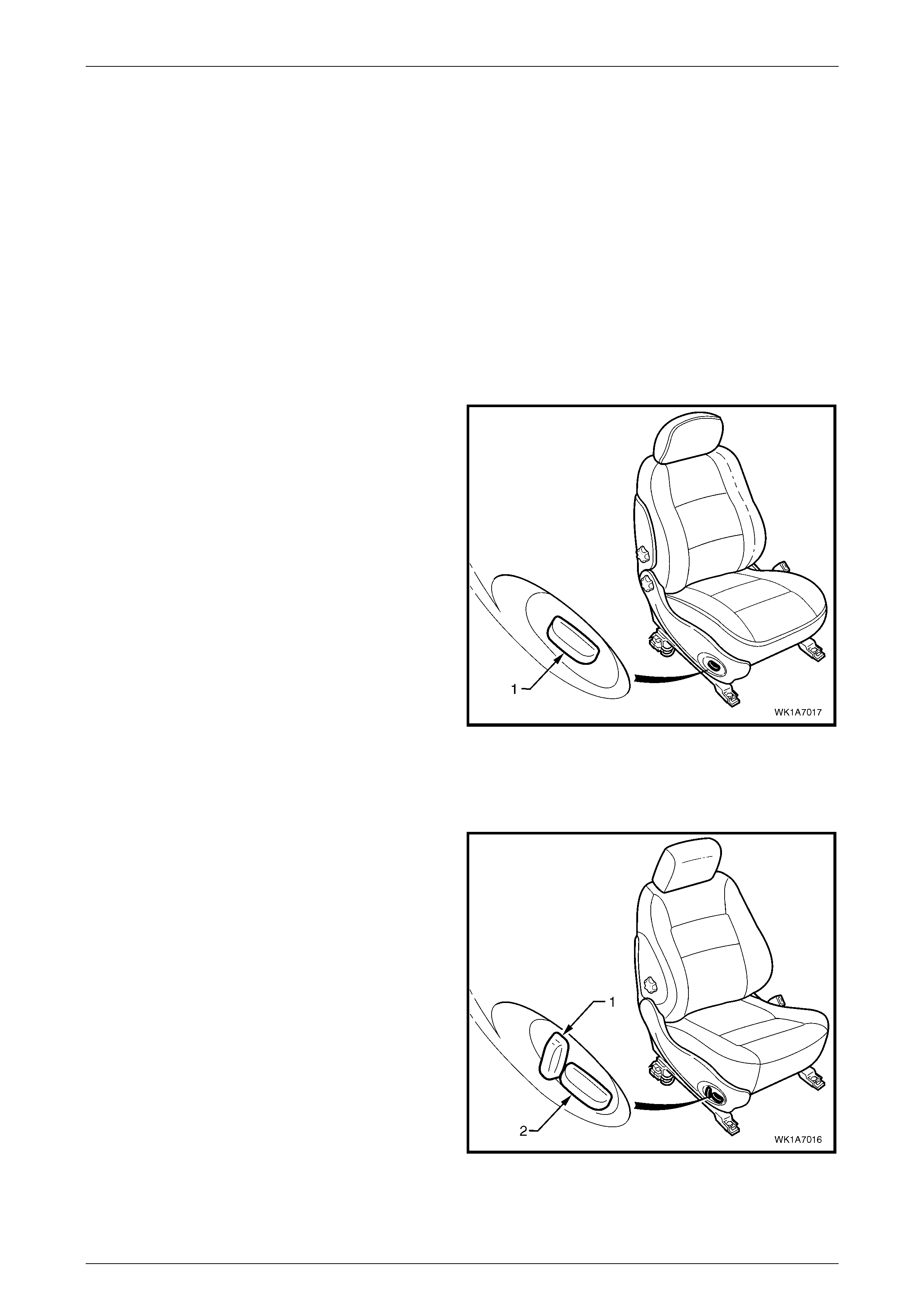
Seat Assemblies Page 1A7–14
Page 1A7–14
Fore/Aft Movement
To provide seat fore/aft movement, the motor and gearbox assembly (3, refer to Figure 1A7 – 1) is connected to a shaft
geared at each end. Within each seat track, the shaft gear is meshed upon a rack, providing fore/aft movement.
Recline Movement
Seat-back recline movement is provided by the recline motor and gearbox assembly (4, refer to Figure 1A7 – 1), which is
attached to the seat-back frame. A shaft from the gearbox is fitted with a drive ge ar at each end and is meshed with a
driven gear attached to each seat-back frame pivot. Motor operation causes rotation of the drive gear, which turns the
driven gear and seat-back frame, thereby altering the seat-back recline angle.
All motors reverse direction when the polarity at the wiring terminals is reversed, resulting in seat movement in the
opposite direction. During seat position adjustment, the drive motors will cease operation at the end of their travel via an
internal thermal cut-ou t switch, even if the seat adjustment switch is held on.
Components making up the seat-back recline mechanism and track and height adjust assembly are not servic ed.
Four-way and Six-way Movement Control
Four-way and six-way seat movement is controlled by a
front seat adjustment switch assembly (1), which is fitted to
the outer side of each front seat.
For the four-way seat, the switch provides independent
control of the front and rear raise/lower movements.
The six-way front seat adjustment switch provides fore/aft
movement in addition to the four-way movements.
To adjust the seat:
• Operate the switch up or down to raise/lower the seat.
• Operate the front of the switch up or down to
raise/lower the front of the seat.
• Operate the rear of the switch up or down to
raise/lower the rear of the seat.
• Operate the switch forward or backward to move the
seat fore/aft.
For further information, refer to the WK Series Owner's
Handbook.
Figure 1A7 – 2
Eight-way Movement Control
The eight-way front seat adjustment switch has an
additional knob (1) which provi des contr ol of the seat-b ac k
recline movement. The knob (2) provides the same
functions as six-way seats.
To adjust the seat recline:
• Operate the recline knob to adjust the angle of the
seat-back. The seat-back moves in the same direction
to which the switch is moved.
For further information, refer to the WK Series Owner's
Handbook.
Figure 1A7 – 3
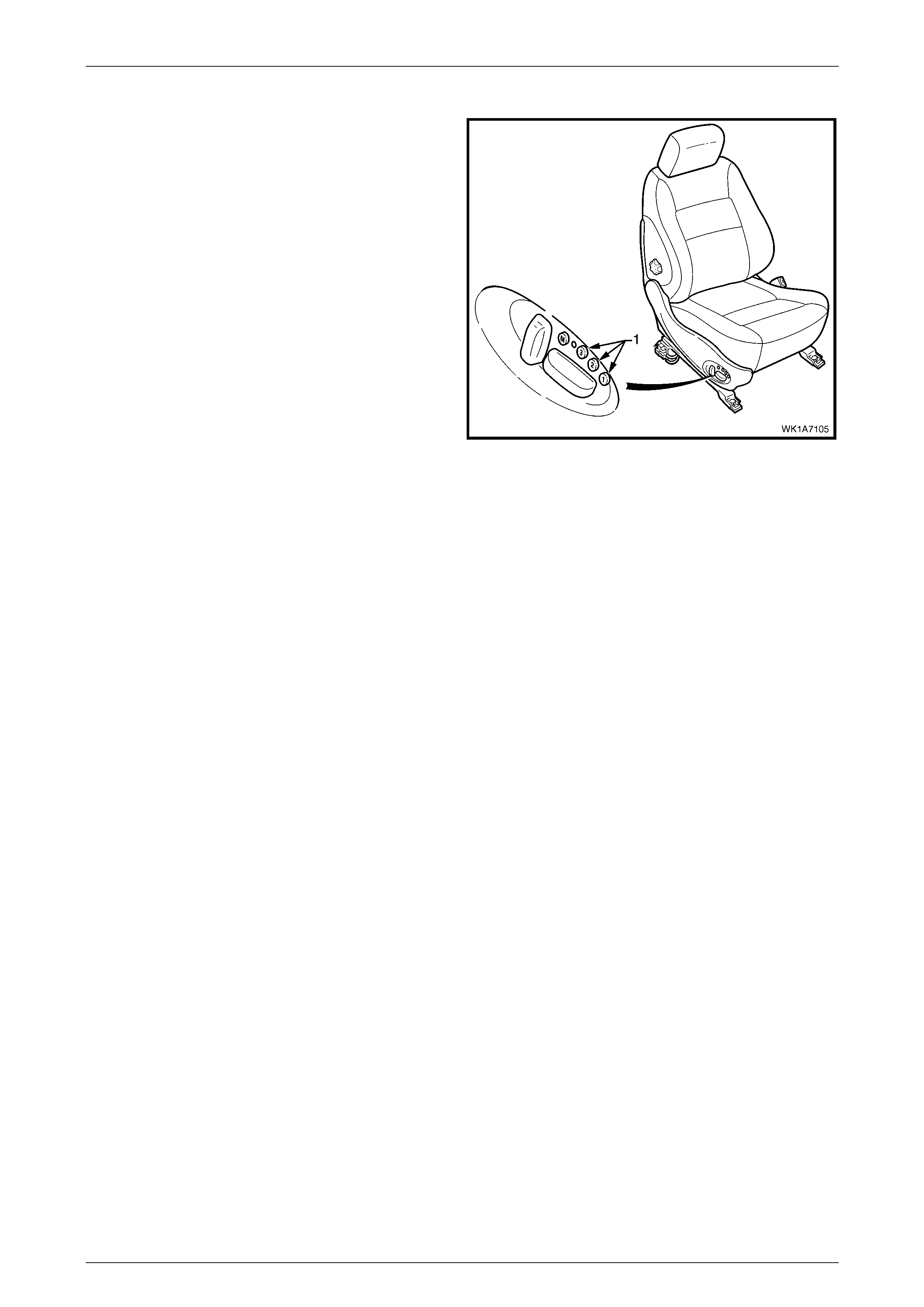
Seat Assemblies Page 1A7–15
Page 1A7–15
Memory Seat Position System
The driver’s seat in Level 5 vehicles is fitted wi th a memory
seat position sy stem .
The memory seat position system allows the driver to adjust
the seat to any of the positions stored in memory by
pressing one of the three memory buttons (1).
In addition, on keyless entry to the vehicle, the memory seat
position system through the Body Control Module (BCM),
recognises which ignition key has been used (Priority 1 or
Priority 2) and adjusts the seat position to the driver’s
preferred set position.
Audible and visual feedback for the various functions of the
memory seat position system is provided. The system has a
green LED and a chime which are used to indicate memory
saves, the recall of priority memory numbers and for seat
diagnost ic pro cedur es.
Four potentiometers mounted with the motor and gearbox
assemblies or on the recline drive shaft monitor the position
of the seat.
Figure 1A7 – 4
The seat memory module, mounted under the front seat, has a non-volatile memory. Whil e disconnecting the battery will
not erase the seat memory settings, the seat will require recalibrating to reset the potentiometer stop values within the
memory control module.
NOTE
Some of the procedures relating to memory seat
diagnosis detailed in 6 Diagnostics – Front Seat,
Level 5 Memory require the use of both the
Priority 1 Key and the Priority 2 Key.
Priority Keys (Level 5 Vehicles Only)
On level 5 vehicles, the driver's seat movement is a function of the priority keys. Priority key 1 and priority key 2 move the
driver's seat and exterior mirrors to the positions in which they were set when that key was last inserted into the ignition
switch. When the vehicle is unlocked using the Unlock button on a priority key and that priority key is inserted into the
ignition switch, the vehicle identifies the priority key and:
• adjusts the position of the driver's seat,
• adjusts the position of the exterior mirrors to the last position used for that key, and
• if the mirror dip function is activated, adjusts the position of the passenger's exterior mirror when the transmission
selector is placed in reverse.
The driver's seat move s to the last position us ed for that priority key if:
• that was a memory button position, or
• the seat was adjusted without memorising the position.
The driver's seat moves to the alternate priority key position only after pressing the UNLOCK button on the alternate
priority key. If the alternate priority key is not used to unlock the vehicle, that priority key will adjust all personalised
settings (for example, exterior mirror angles, radio and climate control), except the driver's seat.
If activated, the left exterior mirror dip function is linked to the seat and priority key memory (that is, each seat memory
position also stores the left exterior mirror DIP position, if activated).
For further information, refer to the WK Series Owner's Handbook.
Memory Buttons
The seat can store three different memory settings. To recall a stored memory seat and exterior mirror position, press
and hold one of the memory buttons. After the seat has reached its memorised position, release the memory button. If
the memory button is released before the seat reaches its memorised position, the seat stops moving.

Seat Assemblies Page 1A7–16
Page 1A7–16
To change a memory position:
1 Adjust the seat with the eight-way front seat adjustment switch.
2 Adjust the exterior mirrors (including the dip position).
3 Place the transmission selector in either park or neutral, then turn the ignition switch on.
4 Press the mirror DIP / memory store button (1, 2 or 3) within five seconds. (Two audible chimes are generated
when a new memory position has been stored.)
5 Place the transmission selector in reverse and wait for the passenger's mirror to be returned from the DIP angle to
complete saving the mirror position into memory, refer to Using the Exterior Mirrors.
Using the Exterior Mirrors
The right exterior mirror and left exterior mirror can be adjusted using the rear-view mirror switch on the driver’s door
armrest when the ignition is on.
To operate the right exterior mirror or left exterior mirror:
1 Turn on the ignition switch.
2 Move the rocker switch on the rear-view mirror switch to the position to control the right or left exterior mirror.
3 Press the rear-view mirror switch in one of the directions indicated by one of the moulded 'dots' on the edge of the
rear-view mirror switch to move the mirror up, down, left or right.
Adjusting the DIP View
To change the mirror dip position and save it in memory:
1 Turn the ignition switch on.
2 Place the transmission selector in reverse.
3 Ensure the DIP angle is switched on; the left exterior mirror moves to the current DIP position.
4 Adjust the left exterior mirror using the eight-way front seat adjustment switch.
5 Place the transmission selector out of reverse.
6 Press the mirror DIP button, then the desired memory store button (1, 2 or 3) to save the mirror dip position into
memory.
For further information, refer to the WK Series Owner's Handbook.
Toggle DIP Function On / Off
When the mirror DIP function is activated, the left exterior mirror moves to the position set, typically enabling the driver to
see the kerb more clearly. If activated, the DIP function is operational when the ignition is on and the transmission
se lector placed in re vers e.
To toggle between the dip view and normal view, press the mirror DIP / memory store button:
• When the DIP function is turned on, two audible chimes are generated.
• When the DIP function is turned off, one audible chime is generated.
For further information, refer to the WK Series Owner's Handbook.
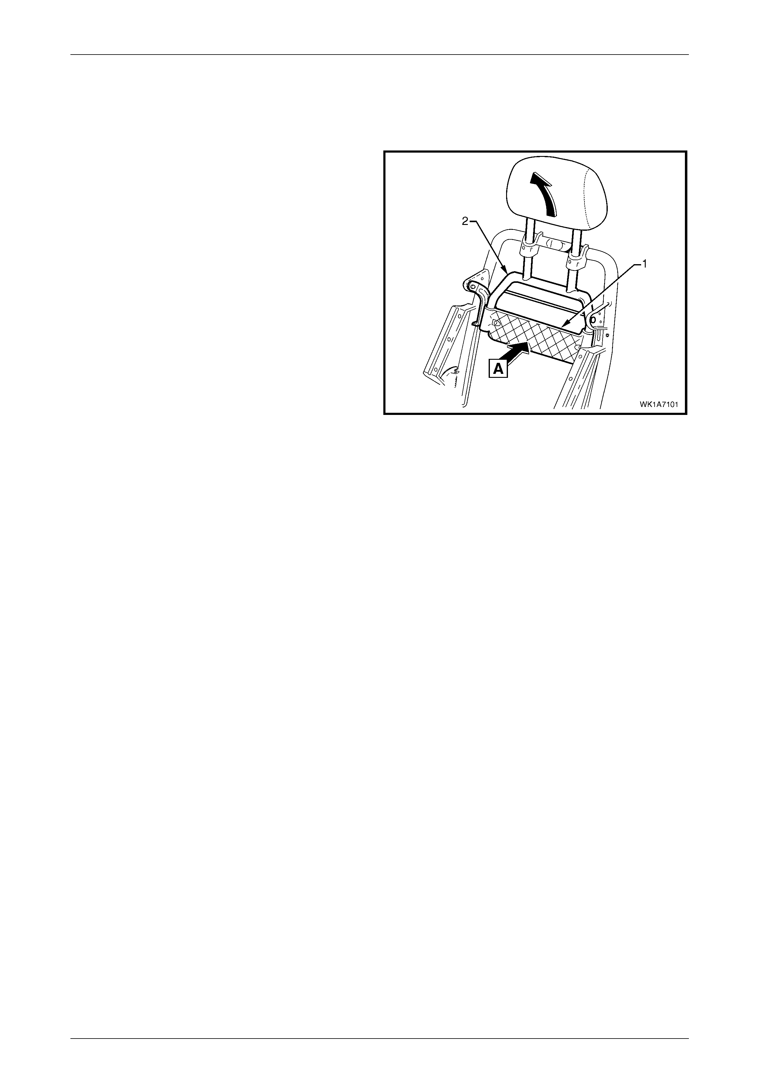
Seat Assemblies Page 1A7–17
Page 1A7–17
Acti ve Head Restrai nts
The front seats fitted to Level 4 and 5 vehicles feature active head restraints. During a rear-end collision, active head
restraints are designed to move upward and forward to support the occupant's head and reduce neck injuries.
The impact force from the collision pushes the vehicle (and
seat) forward. As the vehicle moves forward at a speed
greater than the occupant’s body can react to, the body is
moved into the seat (A) pushing on the active head restraint
support strap (1).
Due to the pivoting of the active head restraint frame (2), the
frame along with the head restraint moves upward and
forward, supporting and li miting rearward travel of the
occupant's head.
Figure 1A7 – 5

Seat Assemblies Page 1A7–18
Page 1A7–18
1.2 Rear Seat General Description
Eight Types of rear seat assemblies are fitted to MY 2004 WK Series vehicles, and depending on vehicle Model Level
feature:
• The option of a two or three passenger rear seat cushion for Level 5,
• A first aid kit pouch in the right-hand rear seat-back assembly, Levels 4 and 5,
• Centre arm rest with deposit box and cup holder, Levels 4 and 5,
• Standard leather trim for Levels 3 and 5 and optional for Levels 2 and 4,
• Centre head restraint for Levels 3 – 5.
Seat Covers
Three seat cover constru cti on meth ods are use d for the rear seat assem bli es:
• Surebond
• Hook and Loop
• Conventional Pull-down
Surebond
Surebond rear seat assemblies are fitted to Level 1 vehicles and have cloth covers that are not serviced separately, as
they are glued to the rear seat cushion and seat-back pads.
Hook and loop
Hook and loop rear seat assemblies are fitted to Level 3 vehicles are fully serviced. They are attached to the rear seat
cushion and seat-back pads using a hook and loop system.
Conventional pull-down
Conventional pull-down rear seat assemblies are fitted to Level 2, 4 and 5 vehicles. Retainer wires are fitted within
casings that are part of the rear seat covers. Hog rings are then used to attach the covers to wires that are moulded
within the cushion or seat-back pads.
For all vehicles, the rear seat cushion frame is serviceable and attaches to the cushion cover retainer wires with hog
rings. The rear seat-back assemblies have the frame moulded as part of the rear seat-back cushion pad and if a
replacement of either part is required, the pad and frame need to be replaced as an assembly.
Seat Assemblies Page 1A7–19
Page 1A7–19
2 Service Operations – Front Seat,
Level 1 and 3
2.1 Front Seat Usage Chart
NOTE
Running changes to the front seat assemblies
fitted to Level 1 and 3 vehicles occurred during
production. Front seat assemblies fitted to the
M 2004 W K prior to this change are referred to as
"early type" Level 1 and 3.
How To Use This Chart
For early type Level 1 and 3 vehicles, six front seat configurations are fitted. The following usage chart is provided to help
determine the seat type fitted to the vehicle. This is important prior to repairs being performed as the failed/damaged part
may not be serviceable. For Level 2, 4 and 5 and late type Level 1 and 3 vehicles refer to 4 Service Operations – Front
Seat, Level 2, 4 and 5.
To determine the seat fitted to the vehicle, obtain the vehicle model, which seat requires attention and the seat cover
fabric. Then establish other features of the seat such as the electric movement functions. Using the chart will lead to the
elimination of all other seat combinations, allowing the identification of the type and the construction of the seat. Finally,
refer to the Figure shown in Front Seat Type for a component breakdown of the front seat assembly.
1 Vehicle – Vehicle model identification. For Model Level definitions refer to Section 0A General Information.
2 Seating – Driver front seat or passenger front seat.
3 Fabric – Cloth or leather seat covers.
4 Movement – Indicates the number of electric movement functions of the seat:
• Four-way – Seat cushion front raise/lower and rear raise/lower,
• Six-way – As Four-way plus seat fore/aft,
• Eight-way – As Six-way plus seat-back recline.
5 Memory – Indicates if a seat memory module is fitted.
6 SIAB – If the front seat is fitted with a side impact airbag assembly.
7 Construction – Surebond refers to the seat cover being glued to the seat pad and only serviced as a cover and
pad assembly. Hook and Loop refers to the seat cover being attached to the seat pad with a Velcro type material
and both being serviced as separate parts.
8 Head Restraint – Indicates whether fixed or active head restraints are fitted.
9 Front Seat Type – Identifies the seat type and provides reference to the following illustrations which show a
breakdown of the serviced component for each front seat assembly.
Gulf States
Vehicle Seating Fabric Movement Memory SIAB Construction Head
Restraint Front Seat Type
(refer to)
Driver Cloth Six-way No No Surebond Fixed 1
(Figure 1A7 – 6)
Passenger Cloth Four-way No No Surebond Fixed 2
(Figure 1A7 – 7)
Driver Cloth Eight-way No No Surebond Fixed 3
(Figure 1A7 – 8)
Early Type
Caprice LS
and Level 1
Passenger Cloth Eight-way No No Surebond Fixed 4
(Figure 1A7 – 9)
Driver Leather Eight-way No Yes Hook & Loop Fixed 5
(Figure 1A7 – 10)
Early Type
Caprice SS
and Level 3 Passenger Leather Eight-way No Yes Hook & Loop Fixed 6
(Figure 1A7 – 11)
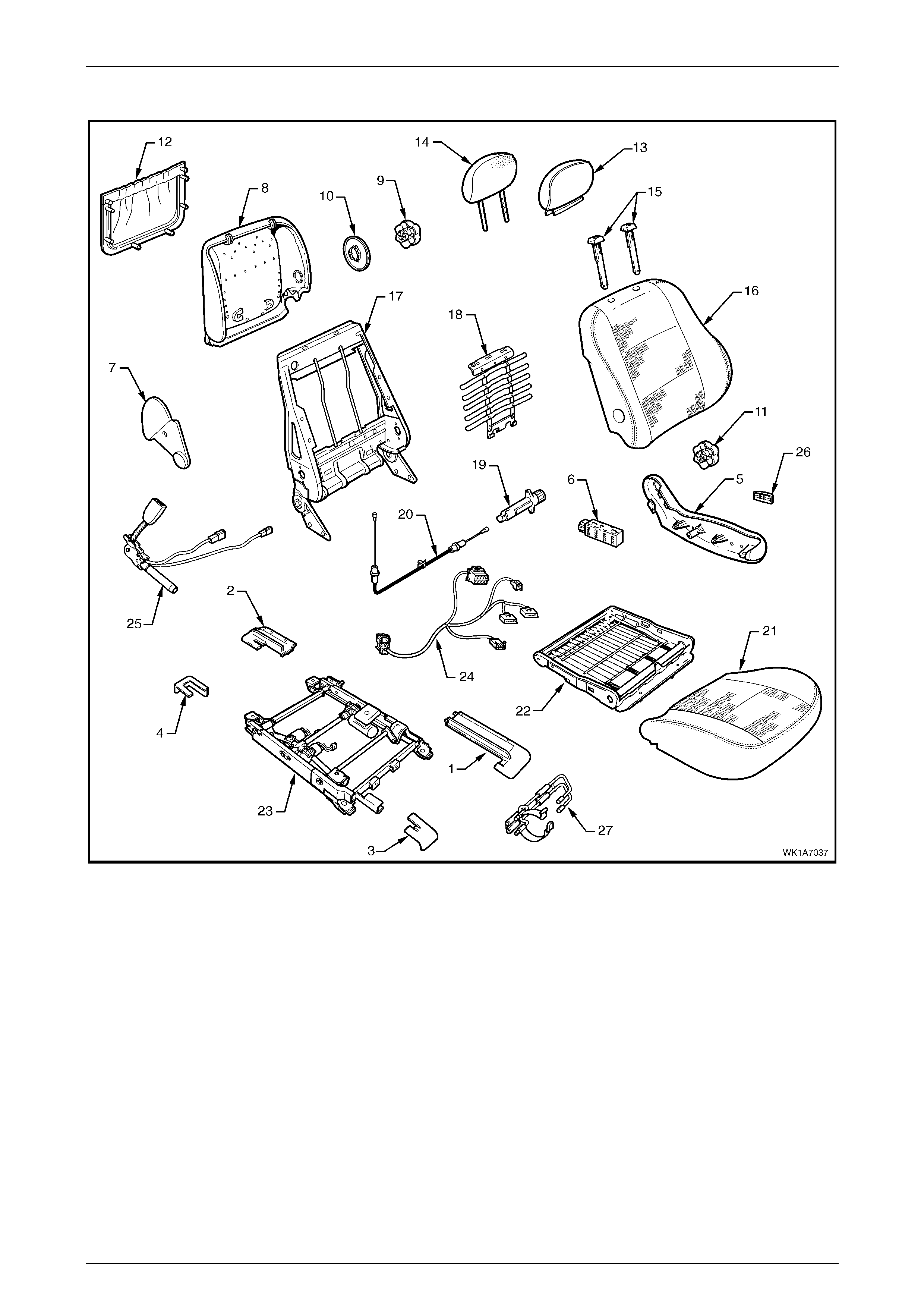
Seat Assemblies Page 1A7–20
Page 1A7–20
Front Seat Type 1
Figure 1A7 – 6
Legend
1 Front Seat Outer Front Cover
2 Front Seat Outer Rear Cover
3 Front Seat Inner Front Cover
4 Front Seat Inner Rear Cover
5 Front Seat Outer Side Cover
6 Front Sea t Adju stment Switch – Six-w a y
7 Front Seat Inner Side Cover
8 Front Seat-back Rear Cover
9 Lumbar Support Knob
10 Lumber Support Deflector Ring
11 Recline Adjuster Knob
12 Front Seat-back Map Pocket
13 Front Seat Head Restraint Cover
14 Front Seat Head Restraint Pad Assembly
15 Front Seat Head Restraint Sleeves
16 Front Seat-back Cover and Pad Assembly
17 Front Seat-back Frame Assembly
18 Lumbar Support Assembly
19 Lumbar Support Adjuster
20 Lumbar Support Adjuster Cable
21 Front Seat Cushion Cover and Pad
22 Front Seat Cushion Frame Assembly
23 Track and Height Adjust Assembl y
24 Wiring Harness Assembly
25 Seatbelt Buckle & Pretensioner Assembly
26 Front Seat Adjustment Switch Knob
27 Fire Extinguisher Mounti ng Bracket
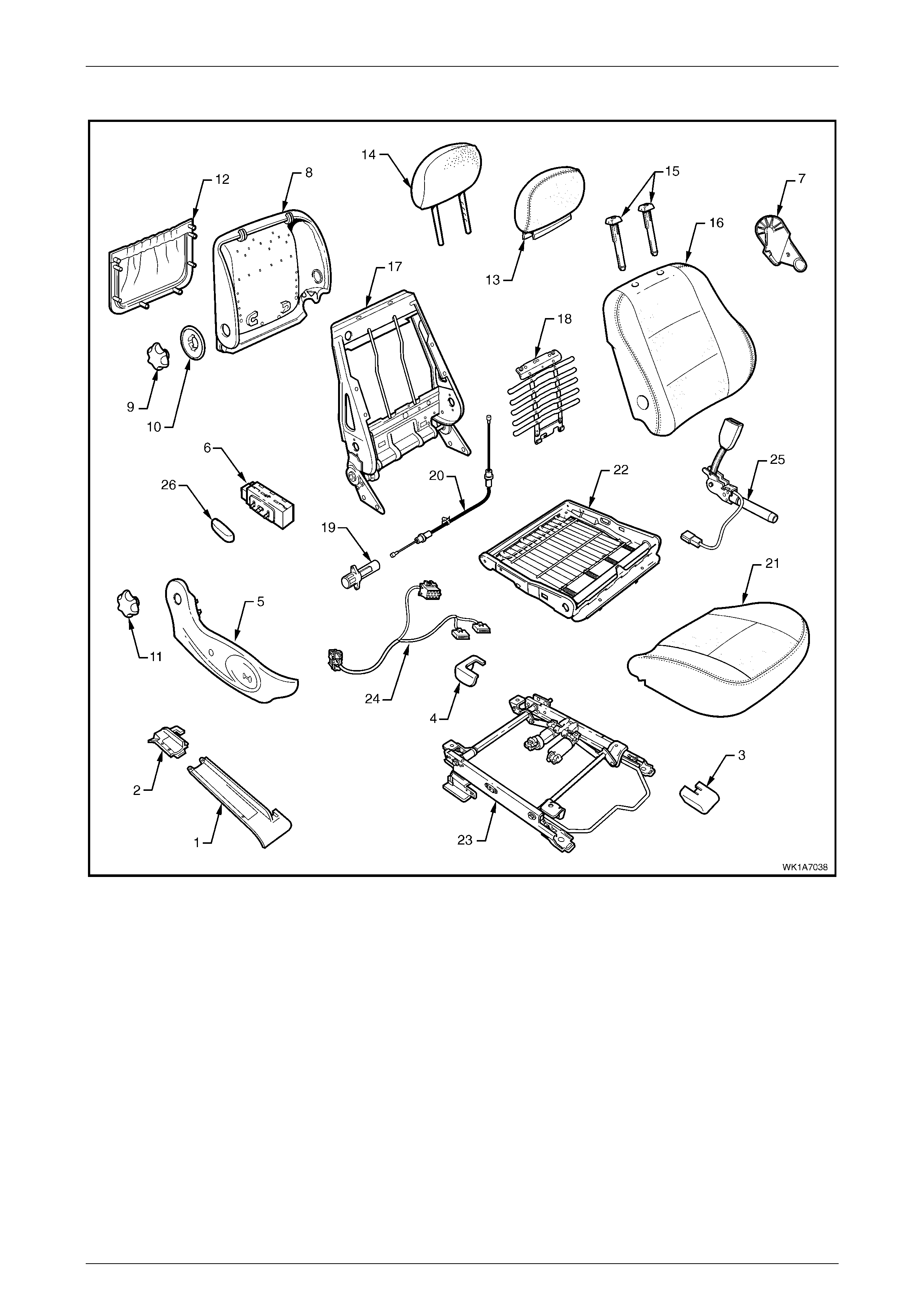
Seat Assemblies Page 1A7–21
Page 1A7–21
Front Seat Type 2
Figure 1A7 – 7
Legend
1 Front Seat Outer Front Cover
2 Front Seat Outer Rear Cover
3 Front Seat Inner Front Cover
4 Front Seat Inner Rear Cover
5 Front Seat Outer Side Cover
6 Front Seat Adjustment Switch – Four-way
7 Front Seat Inner Side Cover
8 Front Seat-back Rear Cover
9 Lumbar Support Knob
10 Lumber Support Deflector Ring
11 Recline Adjuster Knob
12 Front Seat-back Map Pocket
13 Front Seat Head Restraint Cover
14 Front Seat Head Restraint Pad Assembly
15 Front Seat Head Restraint Sleeves
16 Front Seat-back Cover and Pad Assembly
17 Front Seat-back Frame Assembly
18 Lumbar Support Assembly
19 Lumbar Support Adjuster
20 Lumbar Support Adjuster Cable
21 Front Seat Cushion Cover and Pad
22 Front Seat Cushion Frame Assembly
23 Track and Height Adjust Assembl y
24 Wiring Harness Assembly
25 Seatbelt Buckle & Pretensioner Assembly
26 Front Seat Adjustment Switch Knob
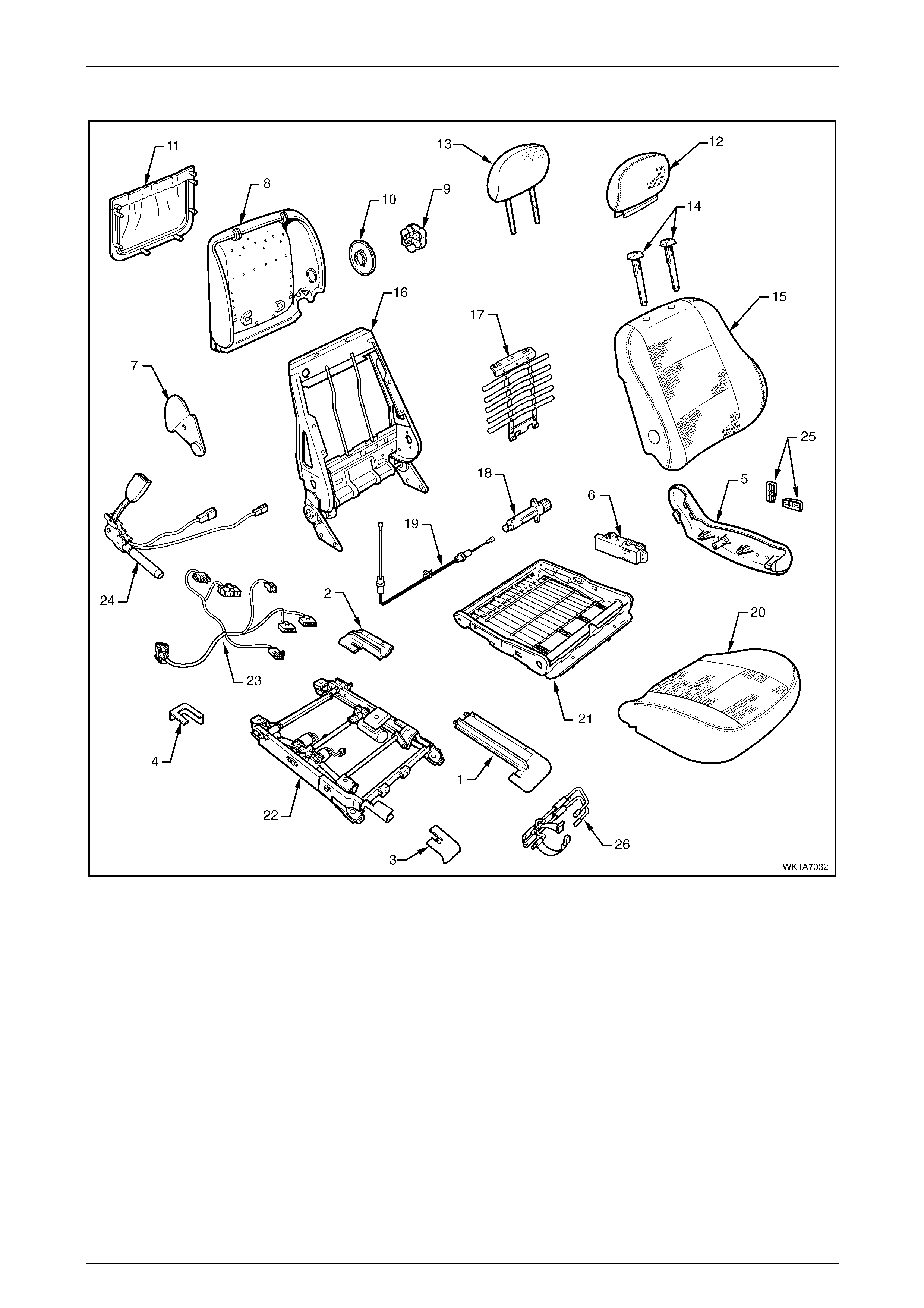
Seat Assemblies Page 1A7–22
Page 1A7–22
Front Seat Type 3
Figure 1A7 – 8
Legend
1 Front Seat Outer Front Cover
2 Front Seat Outer Rear Cover
3 Front Seat Inner Front Cover
4 Front Seat Inner Rear Cover
5 Front Seat Outer Side Cover
6 Front Seat Adjustment Switch – Eight-way
7 Front Seat Inner Side Cover
8 Front Seat-back Rear Cover
9 Lumbar Support Knob
10 Lumber Support Deflector Ring
11 Front Seat-back Map Pocket
12 Front Seat Head Restraint Cover
13 Front Seat Head Restraint Pad Assembly
14 Front Seat Head Restraint Sleeves
15 Front Seat-back Cover and Pad Assembly
16 Front Seat-back Frame Assembly
17 Lumbar Support Assembly
18 Lumbar Support Adjuster
19 Lumbar Support Adjuster Cable
20 Front Seat Cushion Cover and Pad
21 Front Seat Cushion Frame Assembly
22 Track and Height Adjust Assembl y
23 Wiring Harness Assembly
24 Seatbelt Buckle & Pretensioner Assembly
25 Front Seat Adjustmen t Switch Knobs
26 Fire Extinguisher Mounti ng Bracket
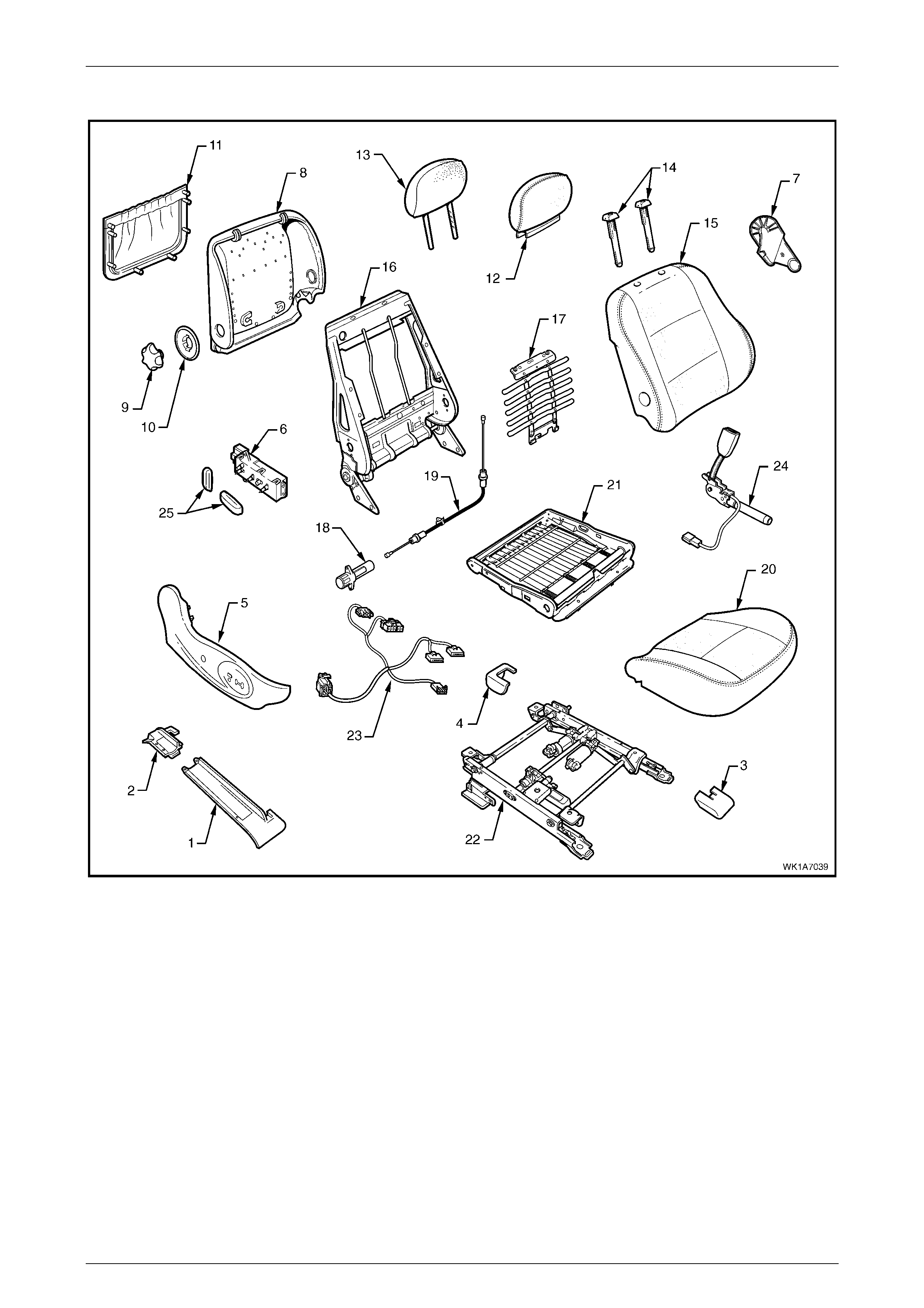
Seat Assemblies Page 1A7–23
Page 1A7–23
Front Seat Type 4
Figure 1A7 – 9
Legend
1 Front Seat Outer Front Cover
2 Front Seat Outer Rear Cover
3 Front Seat Inner Front Cover
4 Front Seat Inner Rear Cover
5 Front Seat Outer Side Cover
6 Front Seat Adjustment Switch – Eight-way
7 Front Seat Inner Side Cover
8 Front Seat-back Rear Cover
9 Lumbar Support Knob
10 Lumber Support Deflector Ring
11 Front Seat-back Map Pocket
12 Front Seat Head Restraint Cover
13 Front Seat Head Restraint Pad Assembly
14 Front Seat Head Restraint Sleeves
15 Front Seat-back Cover and Pad Assembly
16 Front Seat-back Frame Assembly
17 Lumbar Support Assembly
18 Lumbar Support Adjuster
19 Lumbar Support Adjuster Cable
20 Front Seat Cushion Cover and Pad
21 Front Seat Cushion Frame Assembly
22 Track and Height Adjust Assembl y
23 Wiring Harness Assembly
24 Seatbelt Buckle & Pretensioner Assembly
25 Front Seat Adjustmen t Switch Knobs
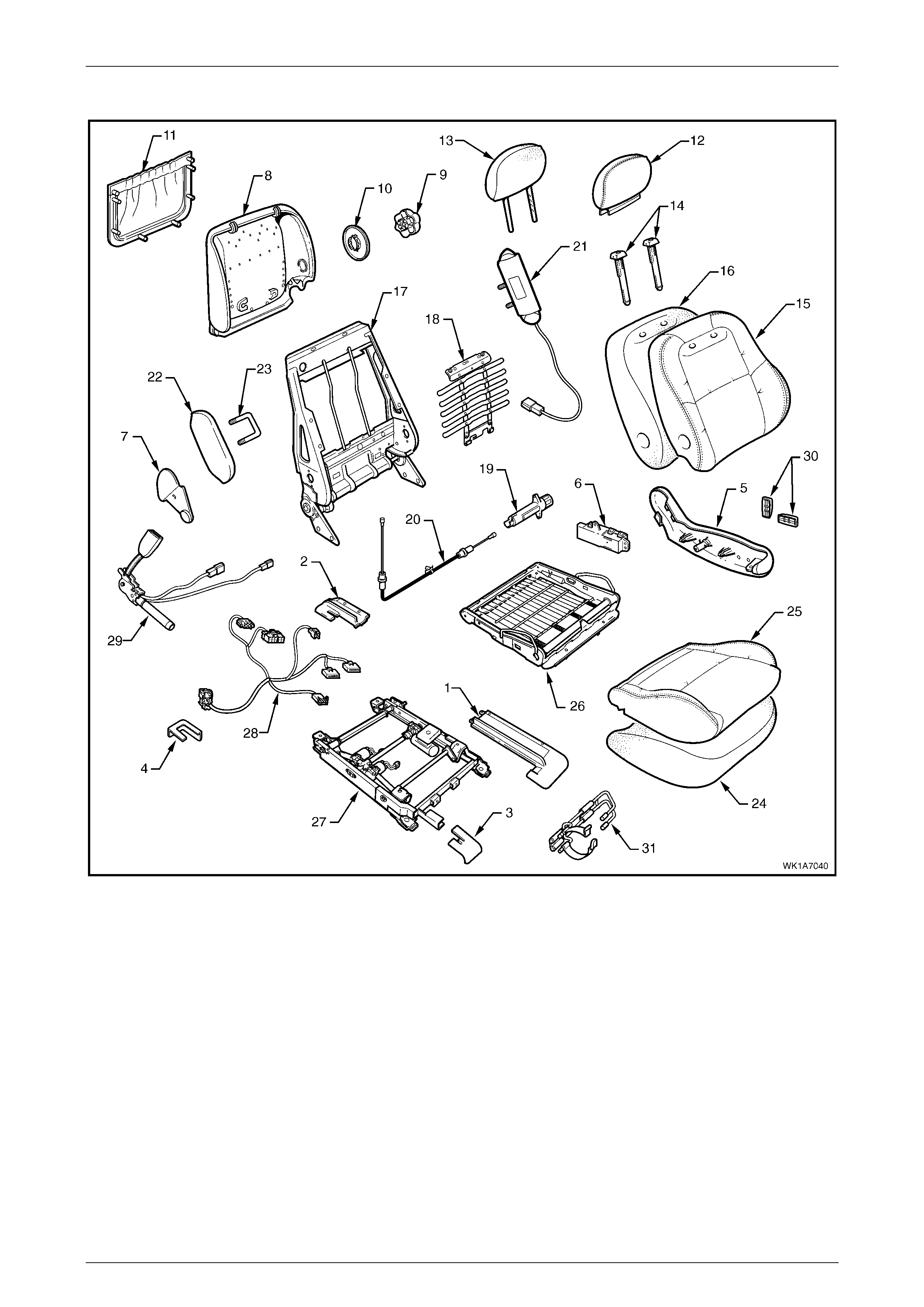
Seat Assemblies Page 1A7–24
Page 1A7–24
Front Seat Type 5
Figure 1A7 – 10

Seat Assemblies Page 1A7–25
Page 1A7–25
Legend
1 Front Seat Outer Front Cover
2 Front Seat Outer Rear Cover
3 Front Seat Inner Front Cover
4 Front Seat Inner Rear Cover
5 Front Seat Outer Side Cover
6 Front Seat Adjustment Switch – Eight-way
7 Front Seat Inner Side Cover
8 Front Seat-back Rear Cover
9 Lumbar Support Knob
10 Lumber Support Deflector Ring
11 Front Seat-back Map Pocket
12 Front Seat Head Restraint Cover
13 Front Seat Head Restraint Pad Assembly
14 Front Seat Head Restraint Sleeves
15 Front Seat-back Cover
16 Front Seat-back Pad
17 Front Seat-back Frame Assembly
18 Lumbar Support Assembly
19 Lumbar Support Adjuster
20 Lumbar Support Adjuster Cable
21 Side Impact Airbag Assembly
22 Front Seat Dummy Block Insert
23 Front Seat Dummy Block U-bolt
24 Front Seat Cushion Pad
25 Front Seat Cushion Cover
26 Front Seat Cushion Frame Assembly
27 Track and Height Adjust Assembl y
28 Wiring Harness Assembly
29 Seatbelt Buckle & Pretensioner Assembly
30 Front Seat Adjustmen t Switch Knobs
31 Fire Extinguisher Mounti ng Bracket
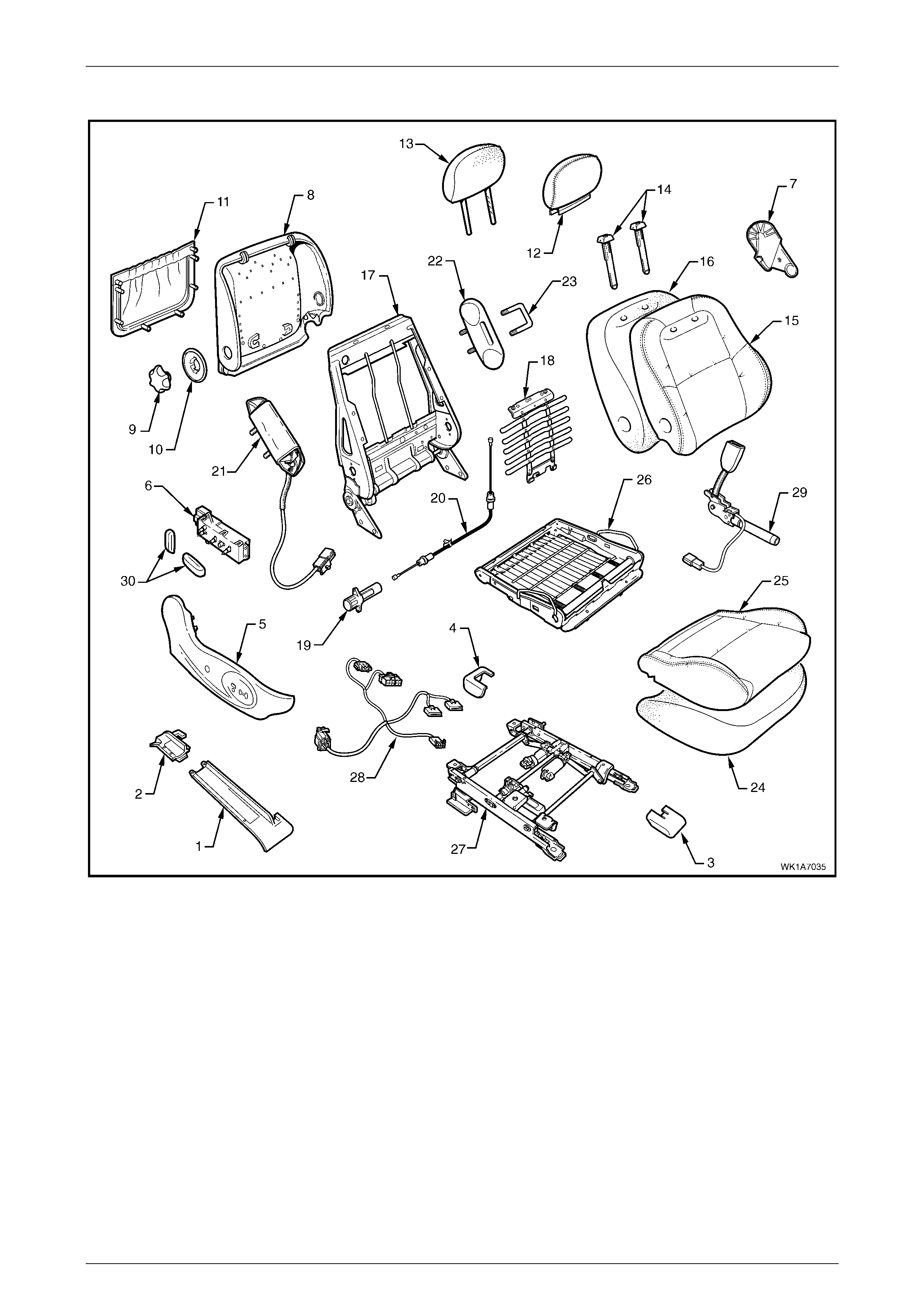
Seat Assemblies Page 1A7–26
Page 1A7–26
Front Seat Type 6
Figure 1A7 – 11

Seat Assemblies Page 1A7–27
Page 1A7–27
Legend
1 Front Seat Outer Front Cover
2 Front Seat Outer Rear Cover
3 Front Seat Inner Front Cover
4 Front Seat Inner Rear Cover
5 Front Seat Outer Side Cover
6 Front Seat Adjustment Switch – Eight-way
7 Front Seat Inner Side Cover
8 Front Seat-back Rear Cover
9 Lumbar Support Knob
10 Lumber Support Deflector Ring
11 Front Seat-back Map Pocket
12 Front Seat Head Restraint Cover
13 Front Seat Head Restraint Pad Assembly
14 Front Seat Head Restraint Sleeves
15 Front Seat-back Cover
16 Front Seat-back Pad
17 Front Seat-back Frame Assembly
18 Lumbar Support Assembly
19 Lumbar Support Adjuster
20 Lumbar Support Adjuster Cable
21 Side Impact Airbag Assembly
22 Front Seat Dummy Block Insert
23 Front Seat Dummy Block U-bolt
24 Front Seat Cushion Pad
25 Front Seat Cushion Cover
26 Front Seat Cushion Frame Assembly
27 Track and Height Adjust Assembl y
28 Wiring Harness Assembly
29 Seatbelt Buckle & Pretensioner Assembly
30 Front Seat Adjustmen t Switch Knobs

Seat Assemblies Page 1A7–28
Page 1A7–28
2.2 Fire Extinguisher Assembly
Remove
1 Remove the fire extinguisher (1) from the cover (2).
2 Remove the two screws (3) attaching the fire
extinguisher mounting bracket (4) to the track and
height adjust assembly.
3 Remove the bracket and cover from the track and
height adjust assembly. If required remove the bracket
from the cover.
Figure 1A7 – 12
Reinstall
Reinstallation of the fire extinguisher assembly is the reverse of the removal procedure, noting the following:
1 Tighten the attaching screws to the correct torque specification.
Fire extinguisher mounting bracket
attaching screw torque specific ation ....... 15.0 – 20.0 Nm
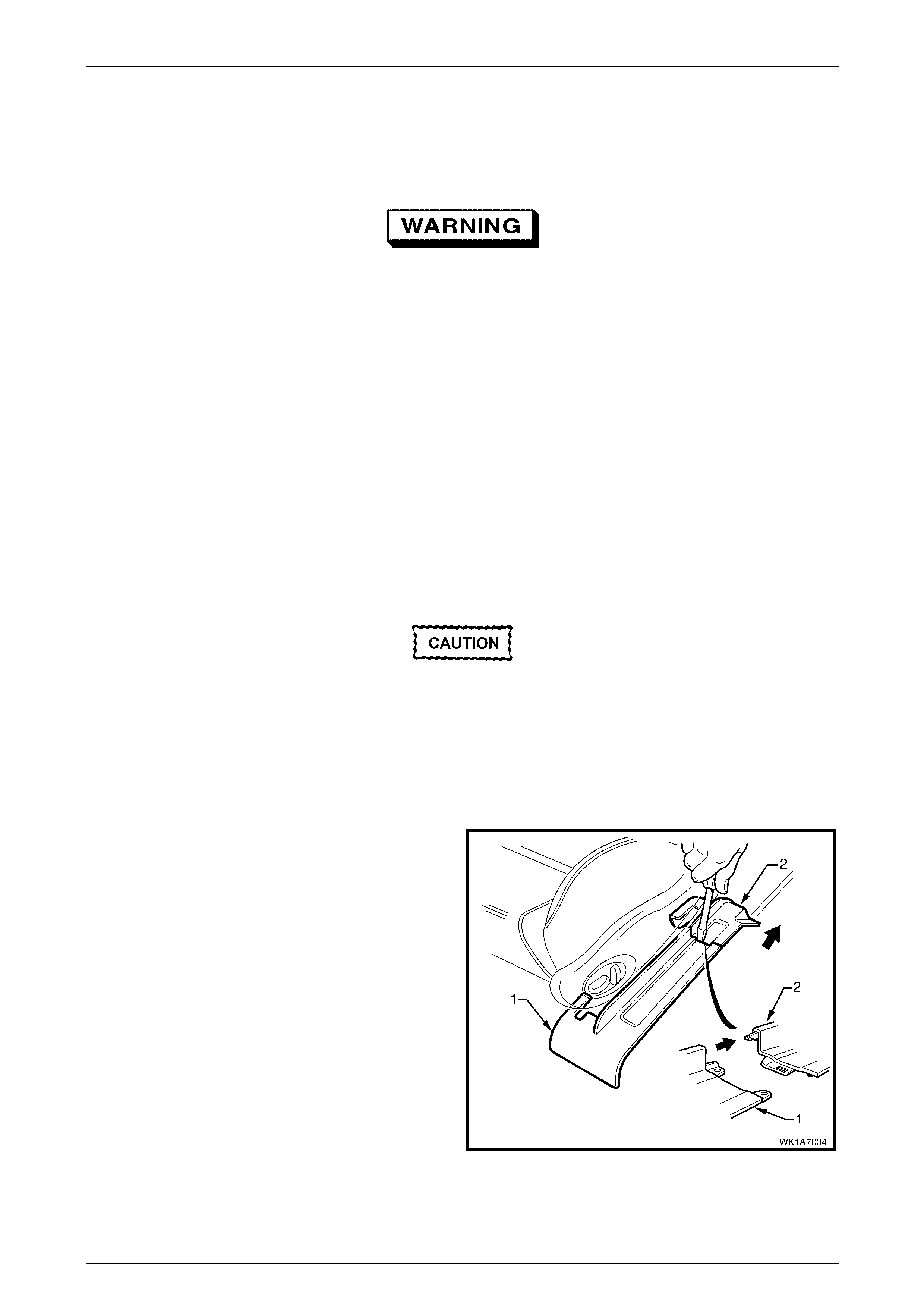
Seat Assemblies Page 1A7–29
Page 1A7–29
2.3 Front Seat Assembly
LT Section No. – 14-295
Before performing any service operation on a
front seat assembly fitted with side impact
airbags, ensure the occupant protection
system is disabled, refer to Section 12M
Occupant Protection System.
NOTE
If the seat assembly is to be disass embled, adjust
the seat assembly to its highest position before
disconnecting the power to the seat.
NOTE
Clean hands are essential when working on the
interior trim.
Remove
Disconnection of the battery affects certain
vehicle electronic systems. Refer to Section
00, 5. Battery Disconnection Procedures
before disconnecting the battery.
1 Disconnect the battery.
2 For the driver’s seat on left-hand drive vehicles, remove the fire extinguisher assembly, refer to
2.2 Fire Extinguisher Assembly.
3 Using a small screwdriver, push in the centre of the
join to separate the front seat outer front cov er (1) and
the front seat outer rear cover (2).
4 Unclip the covers from the seat track and disengage
from the side sill trim.
5 Pull the covers apart and remove the covers.
Figure 1A7 – 13
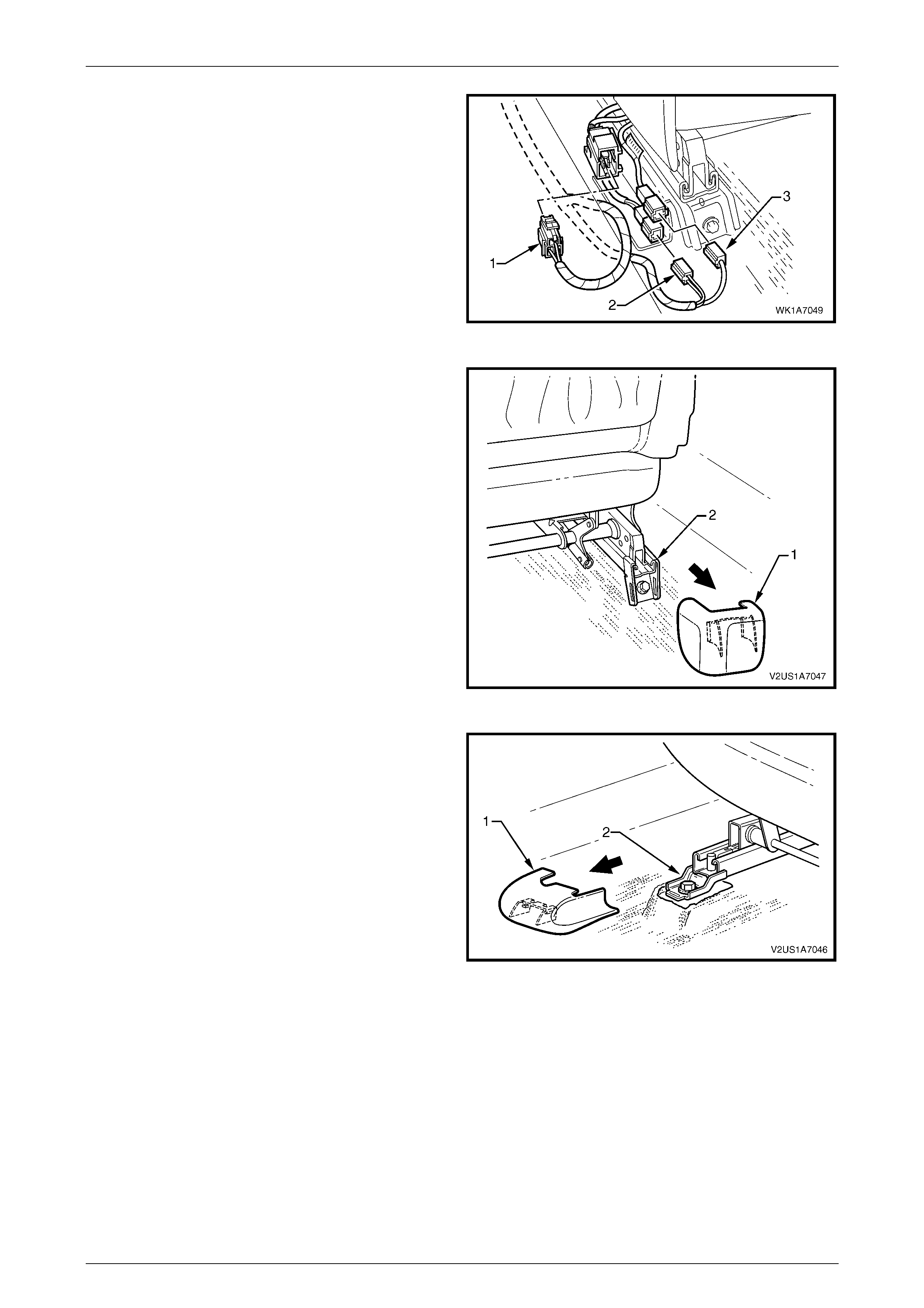
Seat Assemblies Page 1A7–30
Page 1A7–30
6 Disconnect the body wiring harness connector (1),
seatbelt pretens ioner wiring co nnec tor (2) and the side
impact airbag wiring connector (3), if fitted.
Figure 1A7 – 14
7 Unclip the front seat inner rear cover (1) from the seat
track (2).
Figure 1A7 – 15
8 Unclip the front seat inner front cover (1) from the seat
track (2).
Figure 1A7 – 16
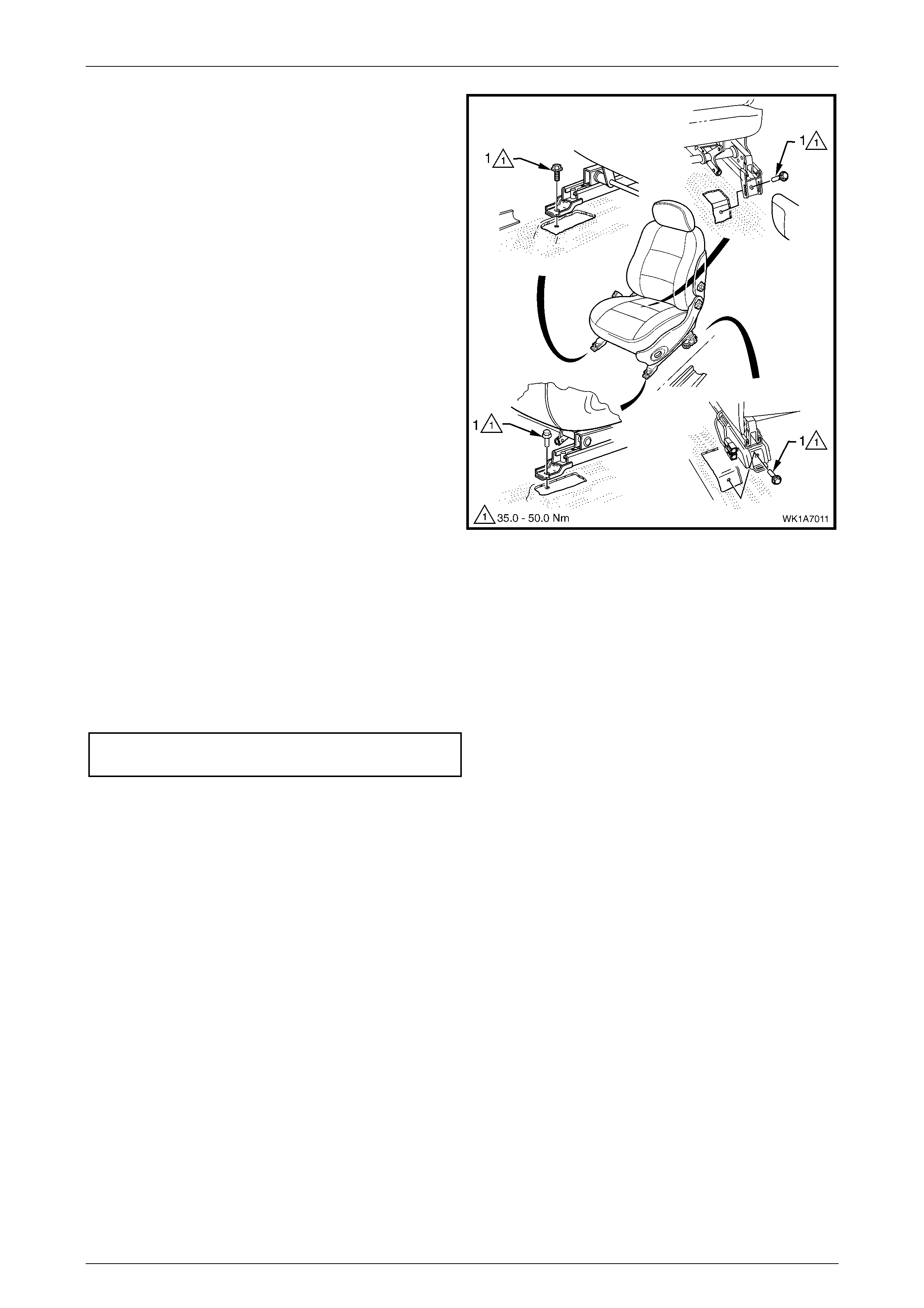
Seat Assemblies Page 1A7–31
Page 1A7–31
9 Remove the four screws (1) attaching the front seat to
the vehicle.
10 Remove the seat from the vehicle.
Figure 1A7 – 17
Reinstall
Reinstall atio n of the front seat ass emb ly is the reverse of the remov al proc edur e, noting the follow ing:
1 Position the front seat assembly into the vehicle.
2 Install the four screws attaching the front seat.
3 Tighten the attaching screws to the correct torque specification.
Front seat assembly attac hing screw
torque specification ................................ 35.0 – 50.0 Nm
4 Connect the seat wiring harness connector, seatbelt pretensioner harness connector and if fitted, the side impact
airbag connector.
5 Align each front seat inner cover’s retaining clips and push firmly to engage.
6 Push the front of the front seat outer cover down to engage the cover wi th the front of the seat rail.
7 Check the operation of the front seat functions. While checking the seat adjustment/operation, also check that the
seat wiring harnesses do not foul with any of the seat’s moveable components (i.e. seat motor drive shafts, etc.).
8 If the seat is fitted with a side impact airbag, switch the ignition on and observe the airbag warning indicator in the
instrument cluster.
• If no fault is detected, the airbag warning indicator should illuminate for approximately five seconds while the
system performs a self-test, and then go off.
• If a fault is present, the airbag warning indicator will remain illuminated and a warning chime may sound after
approximately three seconds. The warning message ‘SRS Airbag Fault’ is also displayed in the instrument
cluster multi-function display. To diagnose the fault, refer to Section 12M, 4 Diagnostics.
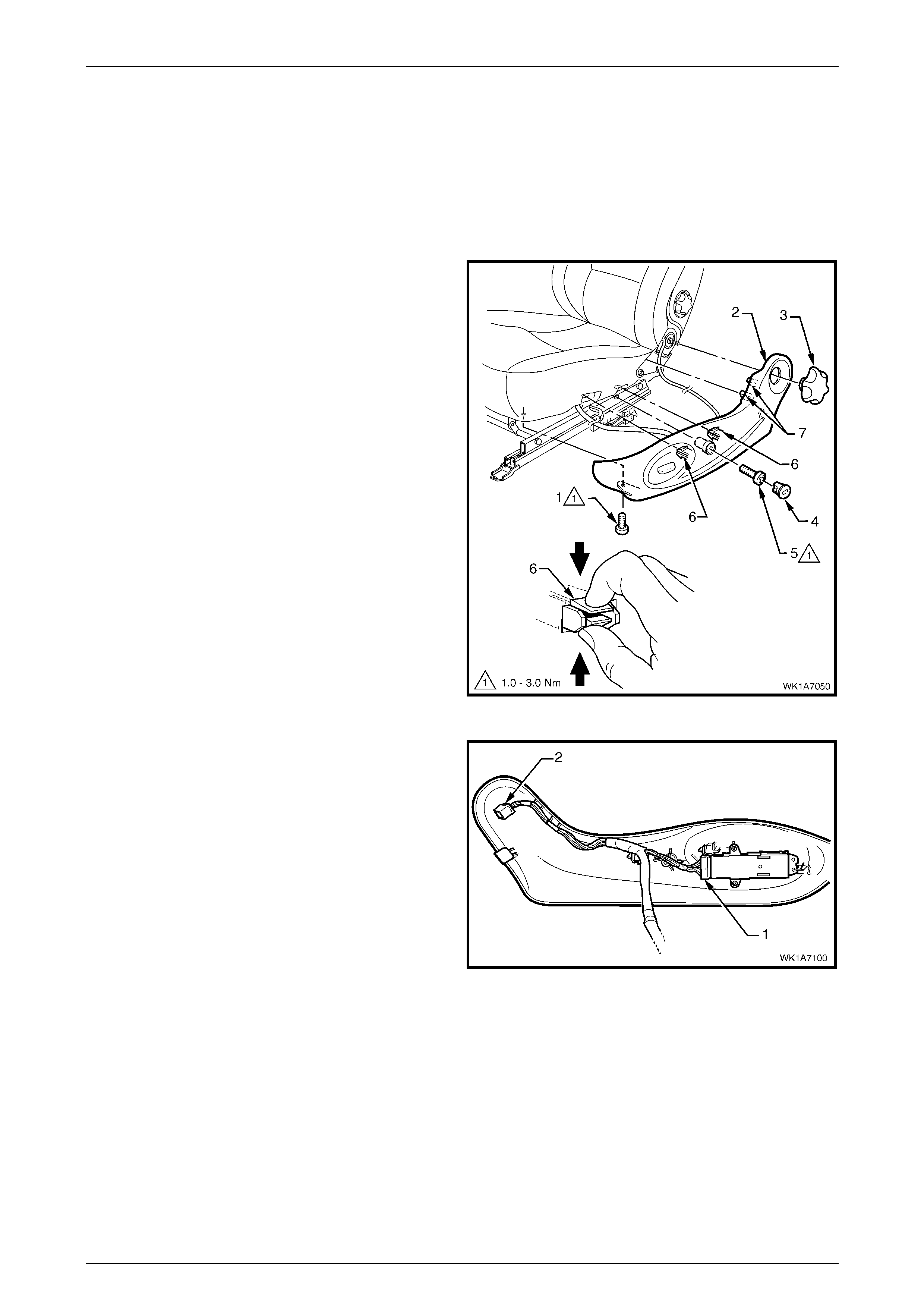
Seat Assemblies Page 1A7–32
Page 1A7–32
2.4 Front Seat Outer Side Cover Assembly
LT Section No. – 14-322
Remove
1 Raise the seat.
2 From under the front of the seat, remove the screw (1)
attaching the front seat outer si de cover (2).
3 For Type 1 and 2 seats, remove the recliner knob (3).
4 Remove the plug (4) by rotating the plug anti-
clockwise, one quarter of a turn.
5 Remove the screw (5) located behind the plug.
6 Reach up under the seat assembly and squeeze the
two retaining tangs (6) together, (two places) on the
inner side of the cover while gently pulling the cover
away from the seat.
7 Gently pull the outer cover away from the seat-back
recliner to disengage the two clips (7) attached to the
swat-back frame assembly.
NOTE
Only remove the outer cover far enough away
from the seat cushion assembly to gain access
to the seat wiring harness connectors.
Figure 1A7 – 18
8 Disconnect the front seat adj u stme nt switch conne ctor
(1).
9 For Type 3 – 6 seats, also remove the recline motor
assembly connector (2).
10 Unclip the wiring harness as required and remove the
cover.
Figure 1A7 – 19
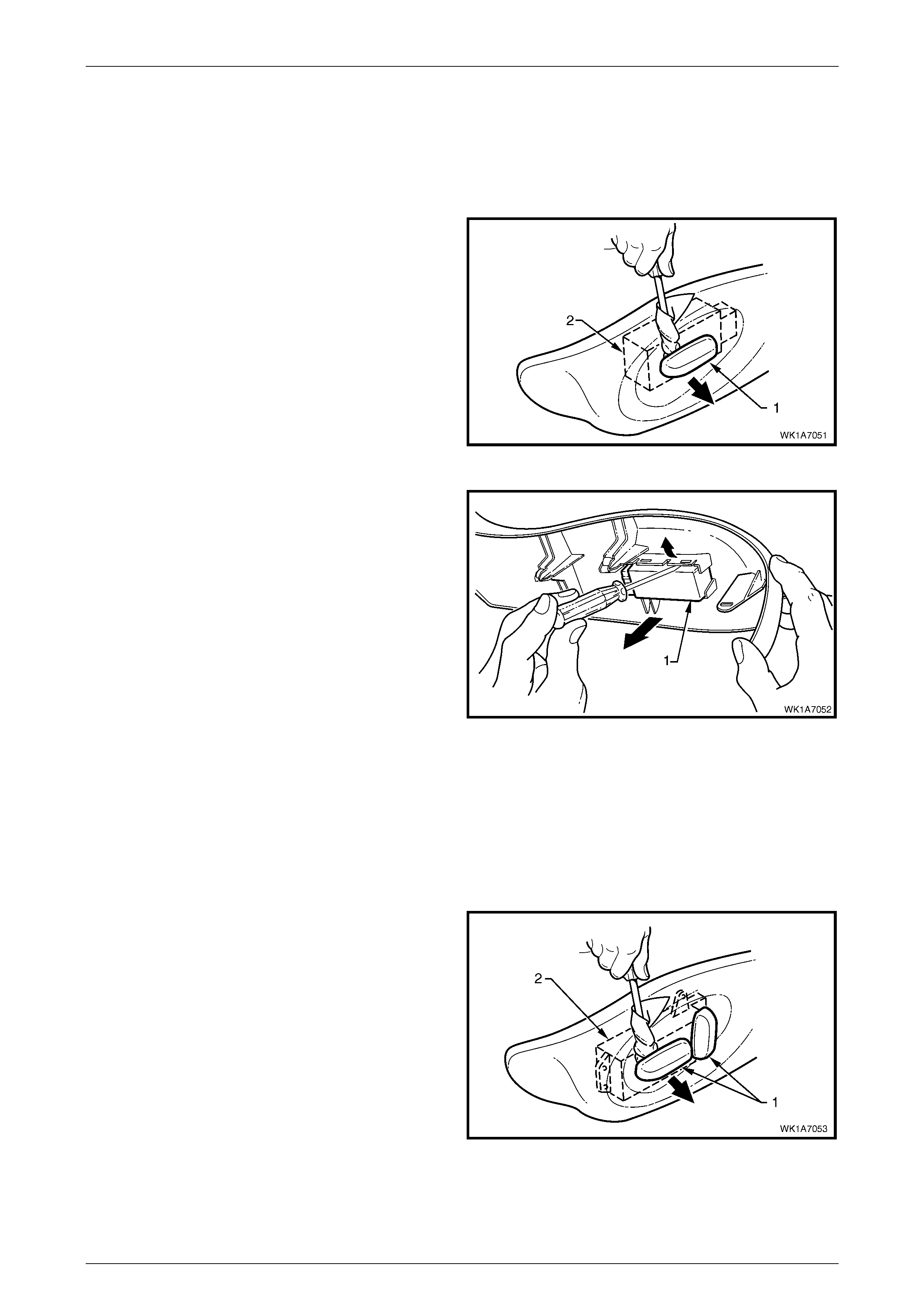
Seat Assemblies Page 1A7–33
Page 1A7–33
Disassemble
Front Seat Adjustment Switch, Front Seat Type 1 and 2
Remove
1 Remove the adjustment knob (1) from the front seat
adjustment switch (2), by carefully prising it free with a
small flat blade screwdriver wrapped in a clean shop
rag.
Figure 1A7 – 20
2 Using a small flat blade screwdriver, gently prise the
front seat adjustmen t sw itch (1 ) from the outer side
cover.
Figure 1A7 – 21
Reinstall
Reinstall the front seat adjustment switch ensuring it is clipped securely in place. Push the knob in until it clicks in pl ace.
Front Seat Adjustment Switch, Front Seat Type 3 – 6
Remove
1 Remove the two adjustment knobs (1) from the front
seat adjustment switch (2), by carefully prising them
free with a small flat blade screwdriver wrapped in a
clean shop rag.
Figure 1A7 – 22
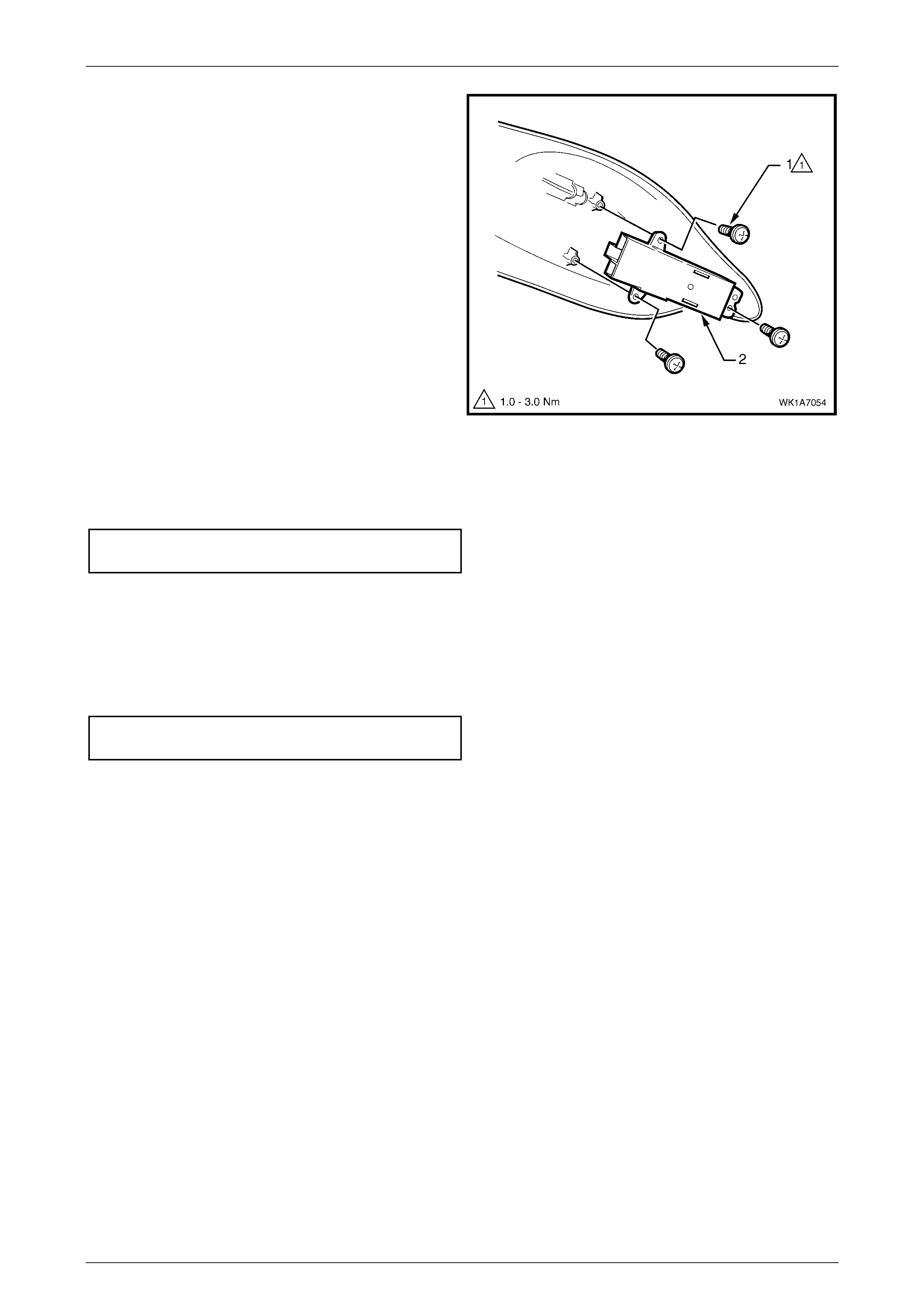
Seat Assemblies Page 1A7–34
Page 1A7–34
2 Remove the three screws (1) attaching the front seat
adjustment switch (2) to the outer side cover.
3 Remove the adjustment switch.
Figure 1A7 – 23
Reinstall
1 Tighten the attaching screws to the correct torque specification.
Front seat adjust ment sw itch
attaching screw torque specific ation ........... 1.0 – 3.0 Nm
2 Push the knobs in until they click in place.
Reinstall
Reinstallation of the front seat outer side cover is the reverse of the removal procedure, noting the following:
1 Tighten the attaching screws to the correct torque specification.
Front seat outer side cover att achi ng
screw torque specification.......................... 1.0 – 3.0 Nm
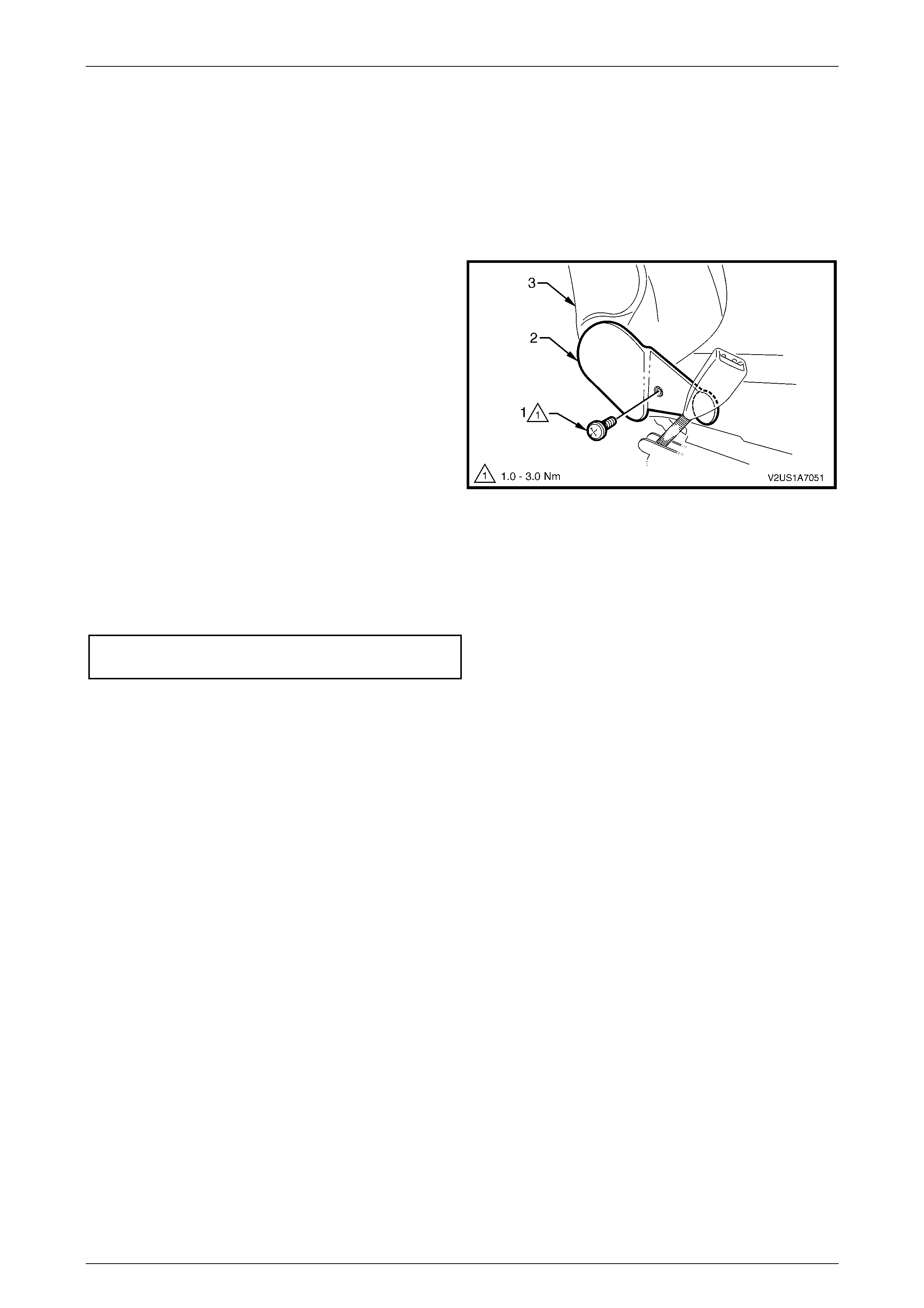
Seat Assemblies Page 1A7–35
Page 1A7–35
2.5 Front Seat Inner Side Cover
LT Section No. – 14-322
As required, remove the front seat assembly, refer to 2.3 Front Seat Assembly.
Remove
1 Remove the screw (1) attaching the front seat inner
side cover (2) to the seat assembly (3) and remove the
cover.
Figure 1A7 – 24
Reinstall
Reinstallation of the front seat inner side cover is the reverse of the removal procedure, noting the following:
1 Tighten the attaching screw to the correct torque specification.
Front seat inner side cover att achi ng
screw torque specification.......................... 1.0 – 3.0 Nm
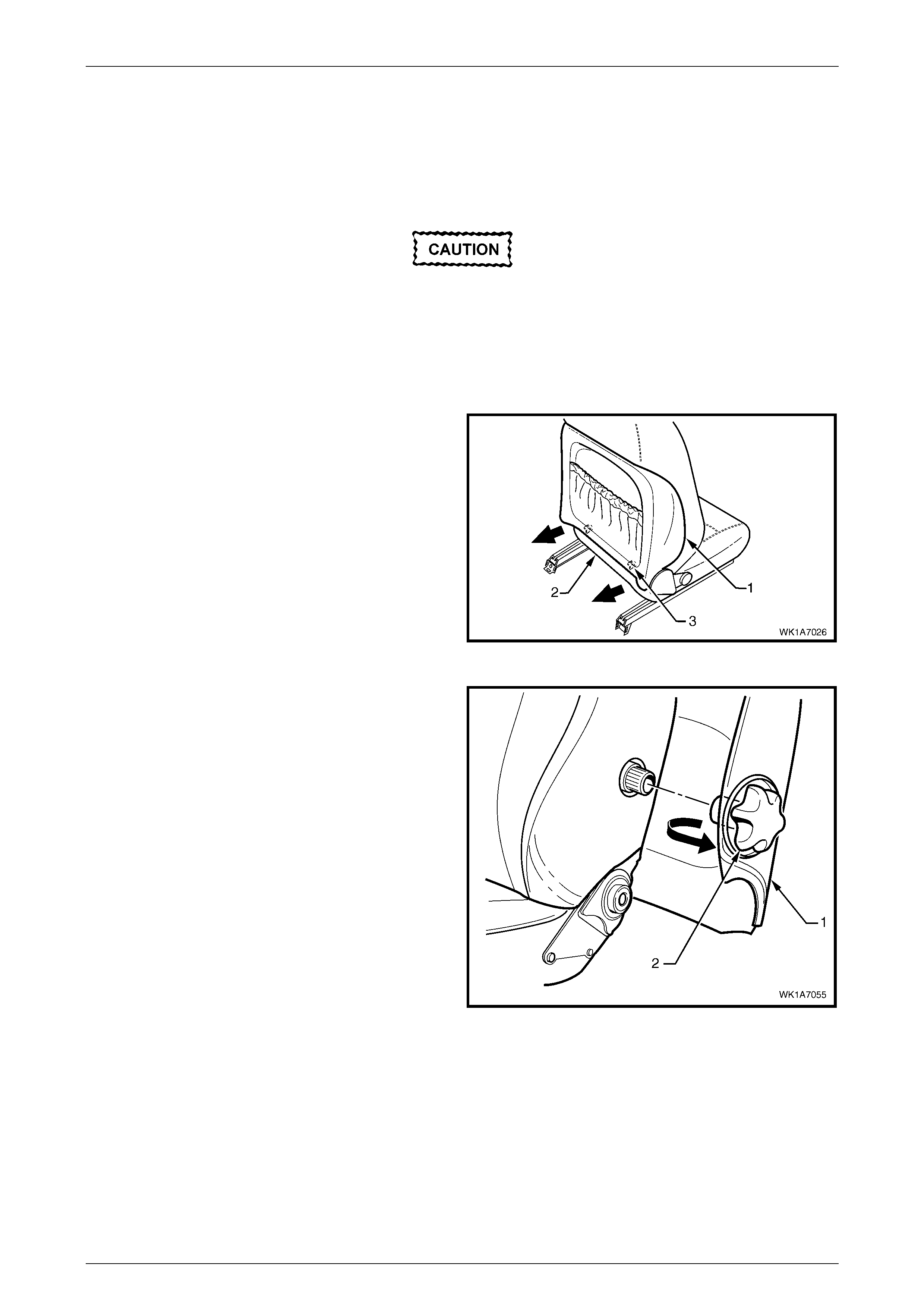
Seat Assemblies Page 1A7–36
Page 1A7–36
2.6 Front Seat-back Rear Co ver Assembly
and Lumbar Support Knob Assembly
LT Section No. – 14-322
The following component will require
replacement when performing this operation.
• Front seat back rear cover retaining clip,
two places
As required, remove the front seat outer side cover, refer to 2.4 Front Seat Outer Side Cover Assembly.
1 Pull the lower corners of the front seat-back rear cover
(1) away from the seat-back (2), breaking the lower
retaining clip (3), two places.
Figure 1A7 – 25
2 Pull the edge of the front seat-back rear cover (1),
forward of the lumbar support adjuster knob (2),
outward to disengage the lumber support knob.
Figure 1A7 – 26
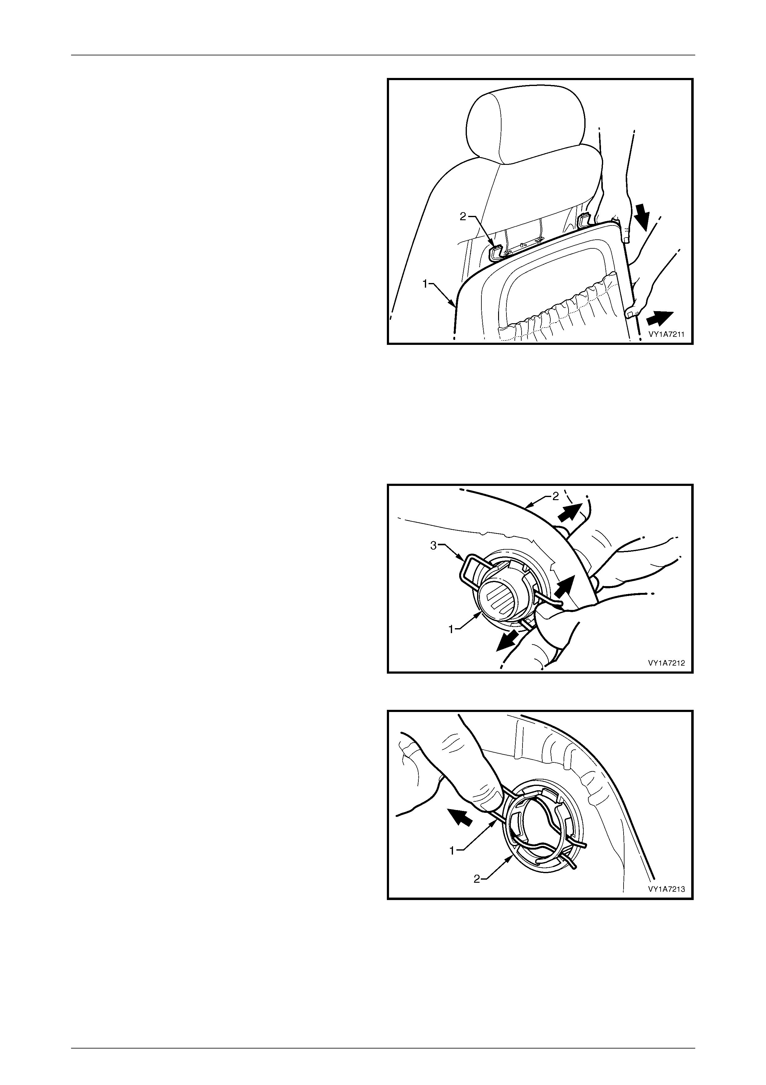
Seat Assemblies Page 1A7–37
Page 1A7–37
3 While holding the side of the front seat-back rear cover
(1) out, pull the cover down to release the upper
retainers (2), two places.
4 Remove the cover.
Figure 1A7 – 27
Disassemble
Lumbar Support Knob and Deflector Ring
Remove
1 Remove the lumbar support knob (1) from the front
seat-back rear cover (2) by spreading the retaining clip
(3) and withdrawing the lumbar support knob.
Figure 1A7 – 28
2 Remove the retaining clip (1) by pulling it from the
lumber support deflector ring (2).
Figure 1A7 – 29
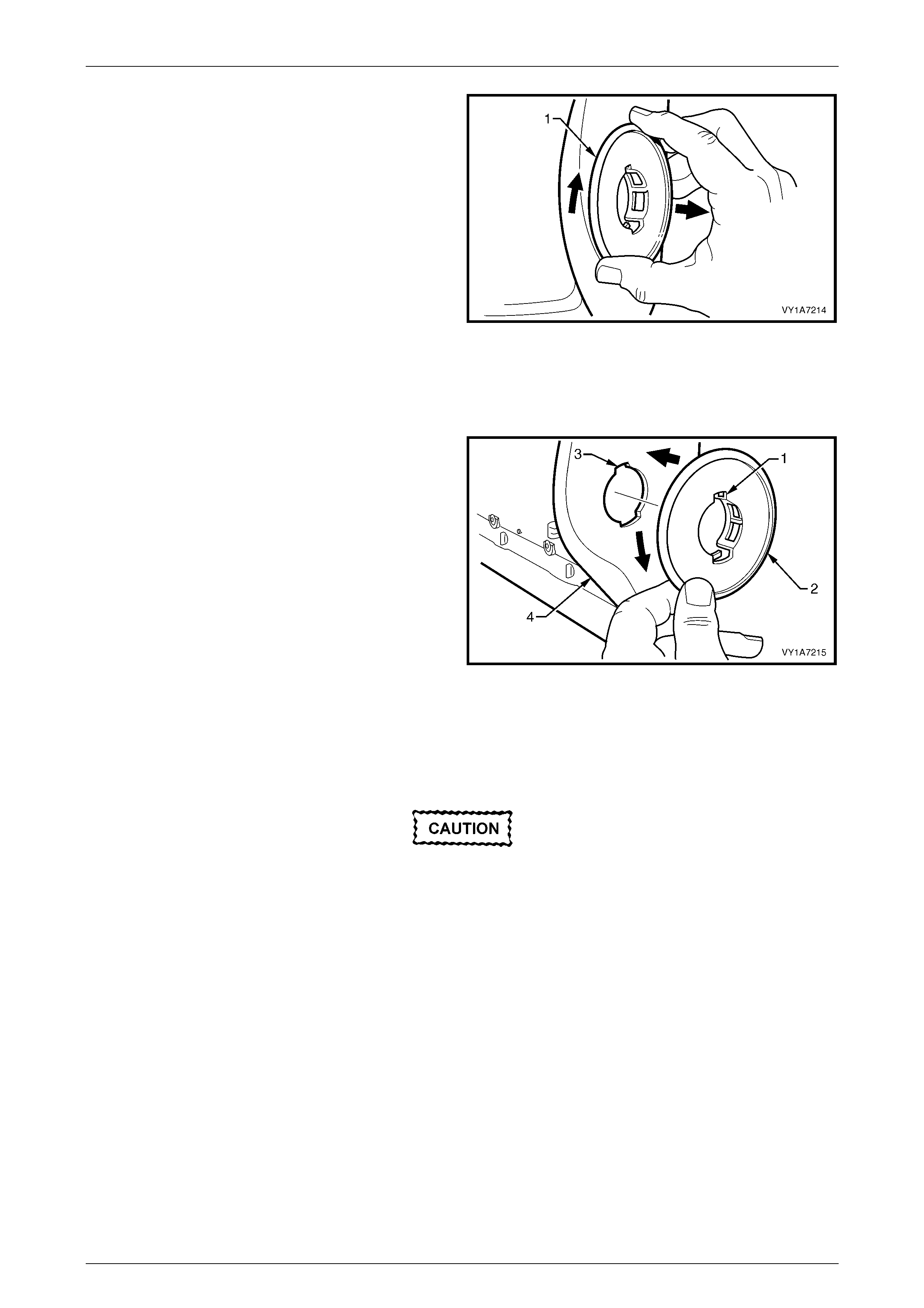
Seat Assemblies Page 1A7–38
Page 1A7–38
3 Rotate the lumber support deflector ring (1)
approximately 90° clockwise and remove from the
front seat-back rear cover.
Figure 1A7 – 30
Reinstall
Reinstallation of the lumbar support knob and deflector ring is the reverse of the removal procedure, noting the following:
1 Align the narrow tab (1) on the lumber support
deflector ring (2) with the narrow key-way (3) in the
front seat-back rear cover (4).
2 Insert the ring into the cover and rotate approximately
90° anti-clockwise until locked in place.
Figure 1A7 – 31
Front Seat-back Map Pocket
Remove
When performing Step 1, take care when
removing the retaining clips not to break the
rear cover pocket shafts on which the clips
are attached.
1 Remove the two retaining clips (1) attaching the front seat-back map pocket (2) to the front seat-back rear cover
(3), refer to Figure 1A7 – 32.
2 Remove the four screws (4) attaching the map pocket to the cover.
3 Remove the map pocket.
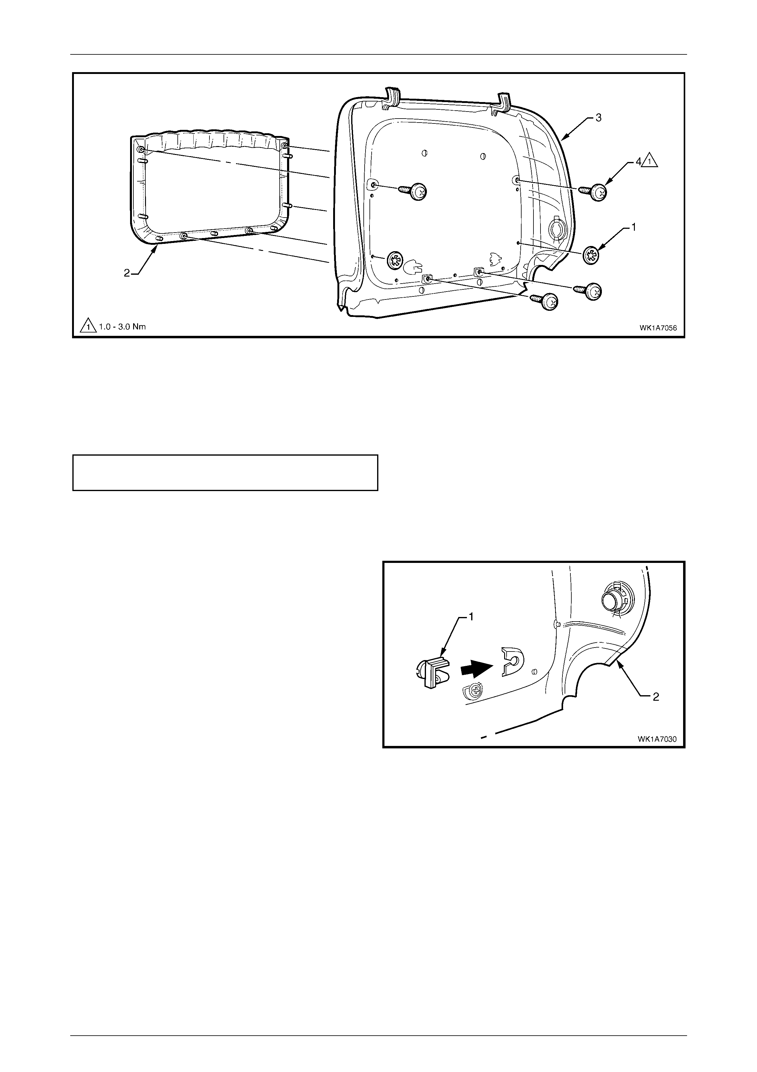
Seat Assemblies Page 1A7–39
Page 1A7–39
Figure 1A7 – 32
Reinstall
Reinstallation of the front seat-back map pocket is the reverse of the removal procedure, noting the following:
1 Tighten the attaching screws to the correct torque specification.
Front seat-back map poc ket
attaching screw torque specific ation ........... 1.0 – 3.0 Nm
Reinstall
Reinstallation of the front seat-back rear cover is the reverse of the removal procedure, noting the following:
1 Replace the damaged retaining clip (1) on the front
seat-back rear cover (2), two places .
Figure 1A7 – 33
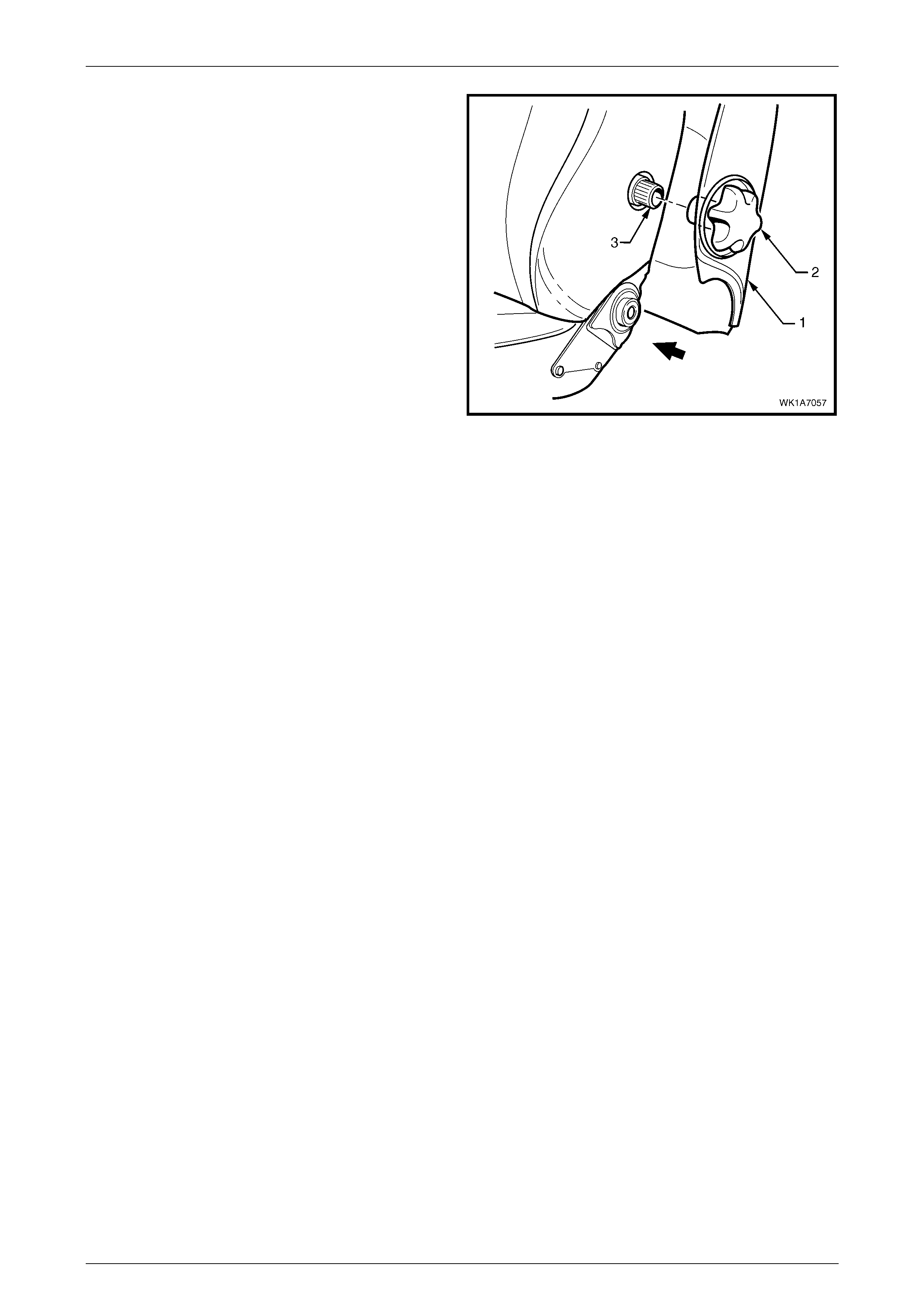
Seat Assemblies Page 1A7–40
Page 1A7–40
2 Pull the side of the front seat-back rear cover (1) out
and align the splines of the lumber support knob (2)
with the splines on the lumbar support adjuster (3).
3 Push the lumber support adjuster knob onto the
lumbar support shaft.
4 Push the seat-back cover into the seat-back to engage
the two lower retaining clips.
Figure 1A7 – 34
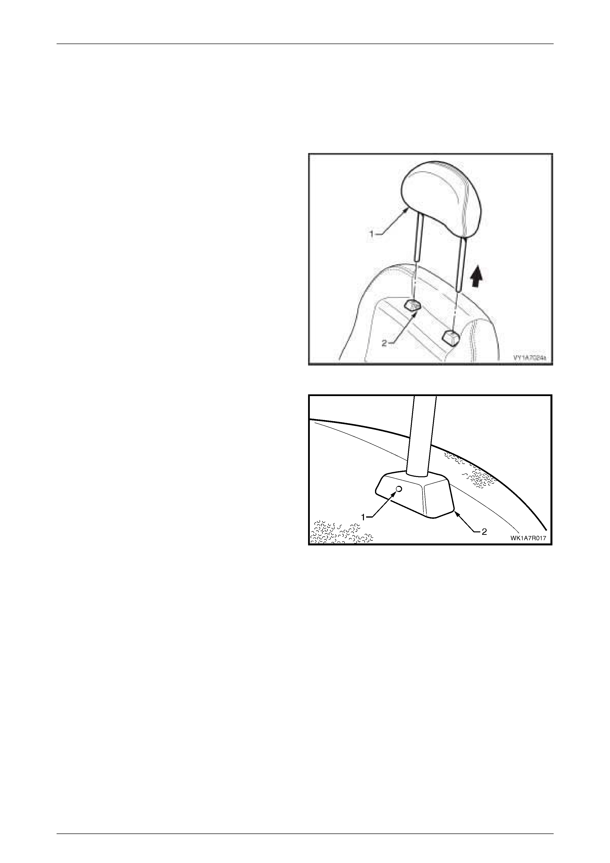
Seat Assemblies Page 1A7–41
Page 1A7–41
2.7 Front Seat Head Restraint Assembly
LT Section No. – 14-295
Remove
1 Raise the head restraint (1) to the first stop position.
2 Depress the head restraint sleeve height adjuster lock
(2) and raise the head restraint to the upper stop
position.
Figure 1A7 – 35
3 Manufacture a suitable size probe and insert into the
hole (1) in the left-hand head restraint sleeve (2).
4 Push the probe in slightly while applying slight upward
pressure on the head restraint and remove the head
restraint completely out of the sleeve.
Figure 1A7 – 36
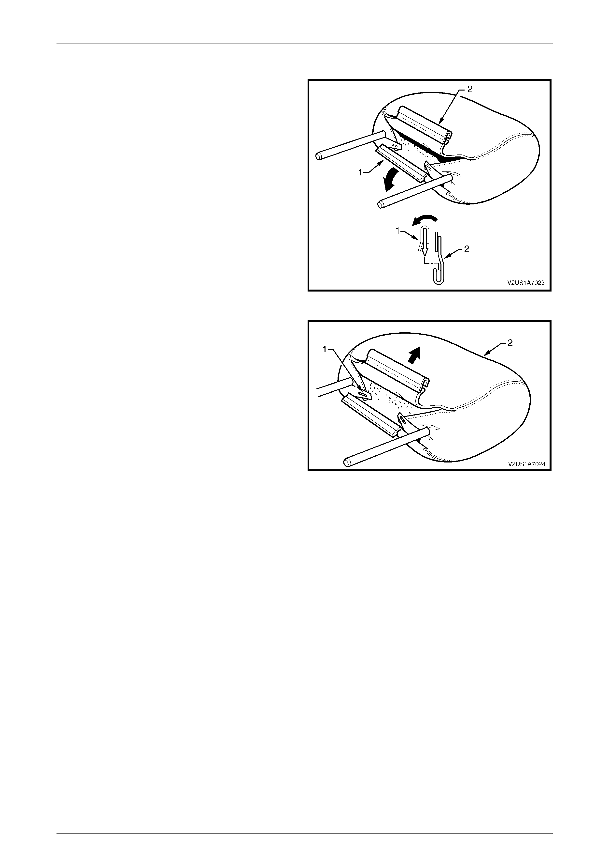
Seat Assemblies Page 1A7–42
Page 1A7–42
Disassemble
1 Disengage the front head restraint cove r J-strip by
pulling the flap (1) back and out of flap (2) in the
direction shown.
Figure 1A7 – 37
2 Remove the staples(1), two places, retaining the cover
(2) to the head restraint pad assembly.
3 Remove the cover from the pad assembly.
Figure 1A7 – 38
Reassemble
Reassembly of the front seat head restraint assembly is the reverse of the disassembly procedure, noting the following:
1 Ensure the head restraint cover J-clip is fully engaged.
Reinstall
Ensuring correct orientation of the head restraint, fit the head restraint shafts into the sleeves and push the head restraint
down.
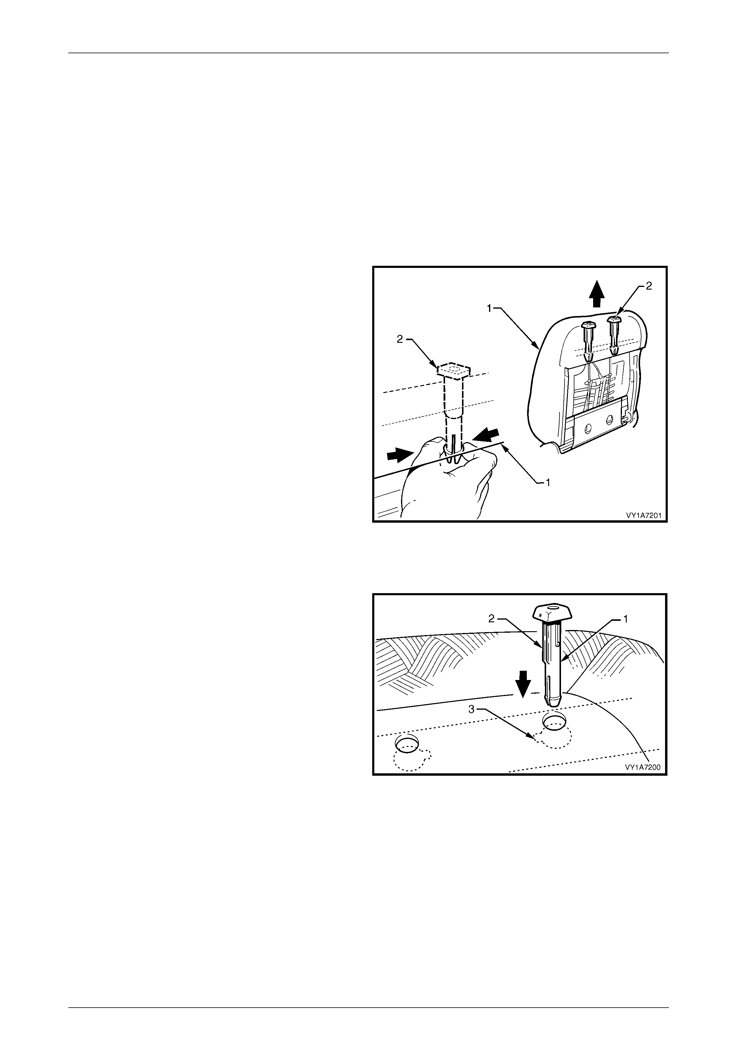
Seat Assemblies Page 1A7–43
Page 1A7–43
2.8 Front Seat Head Restraint Sleeve
LT Section No. – 14-275
As required, remove the following components:
1 Front seat-back rear cover assembly, refer to 2.6 Front Seat-back Rear Cover Assembly and Lumber Support Knob
Assembly.
2 Front seat head restraint assembly, refer to 2.7 Front Seat Head Restraint Assembly.
Remove
1 From the rear of the front seat-back (1), squeeze the
locking prongs of the head restraint sleeve (2) together
while pulling the top of the sleeve out of seat-back
assembly.
2 Repeat for the remaining sleeve as required.
Figure 1A7 – 39
Reinstall
1 When installing the head restr aint sleeve (1), align the
locating ribs (2) with the key-way (3) in the seat-back
frame.
NOTE
Ensure the guide with the height adjuster lock is
installed on the side that corresponds to the
notches in the head restraint shaft.
2 Push the sleeve in firmly.
3 Repeat for the opposite sleeve as required.
Figure 1A7 – 40
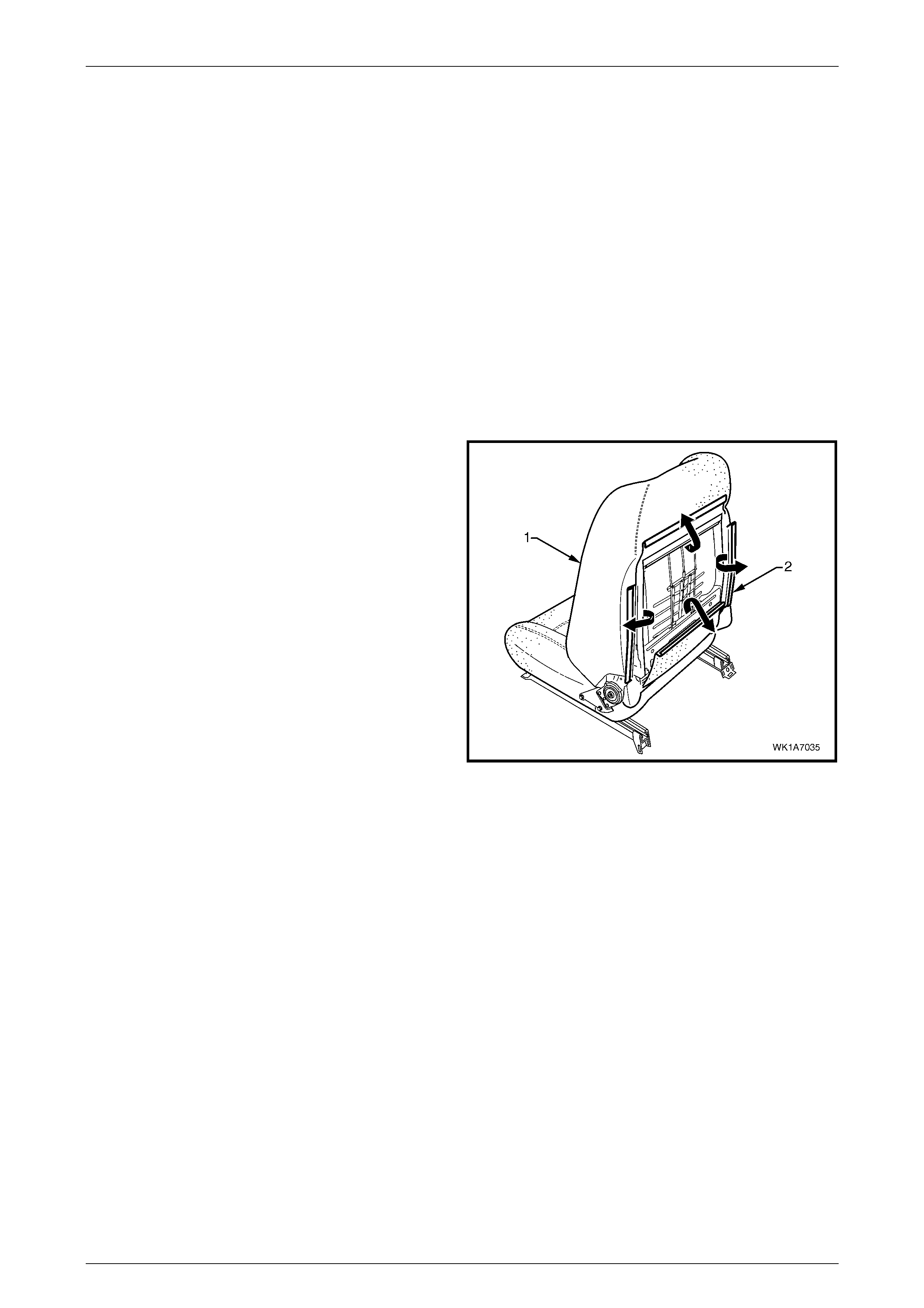
Seat Assemblies Page 1A7–44
Page 1A7–44
2.9 Front Seat-back Pad and Cover
Assembly
LT Section No. – 14-295
As required, remove the following components:
1 Front seat assembly, refer to 2.3 Front Seat Assemb ly.
2 Front seat outer side cover, refer to 2.4 Fron t Seat Outer Side Cover A ssemb ly.
3 Front seat-back rear cover assembly, refer to 2.6 Front Seat-back Rear Cover Assembly and Lumber Support Knob
Assembly.
4 Front seat head restraint assembly, refer to 2.7 Front Seat Head Restraint Assembly.
5 Remove the front seat head restraint sleeves, refer to 2.8 Front Seat Head Restraint Sleeve.
Remove
1 Remove the front seat-back pad and cover assembly
(1) by disengaging the J-strip (2), four places, from the
seat-back frame.
2 Lift the cover and pad assembly up and away from the
seat-back frame, manoeuvring it over the seat-back
components such as the side impact airbag assembly
and front seat dummy block insert assembly, where
fitted.
Figure 1A7 – 41
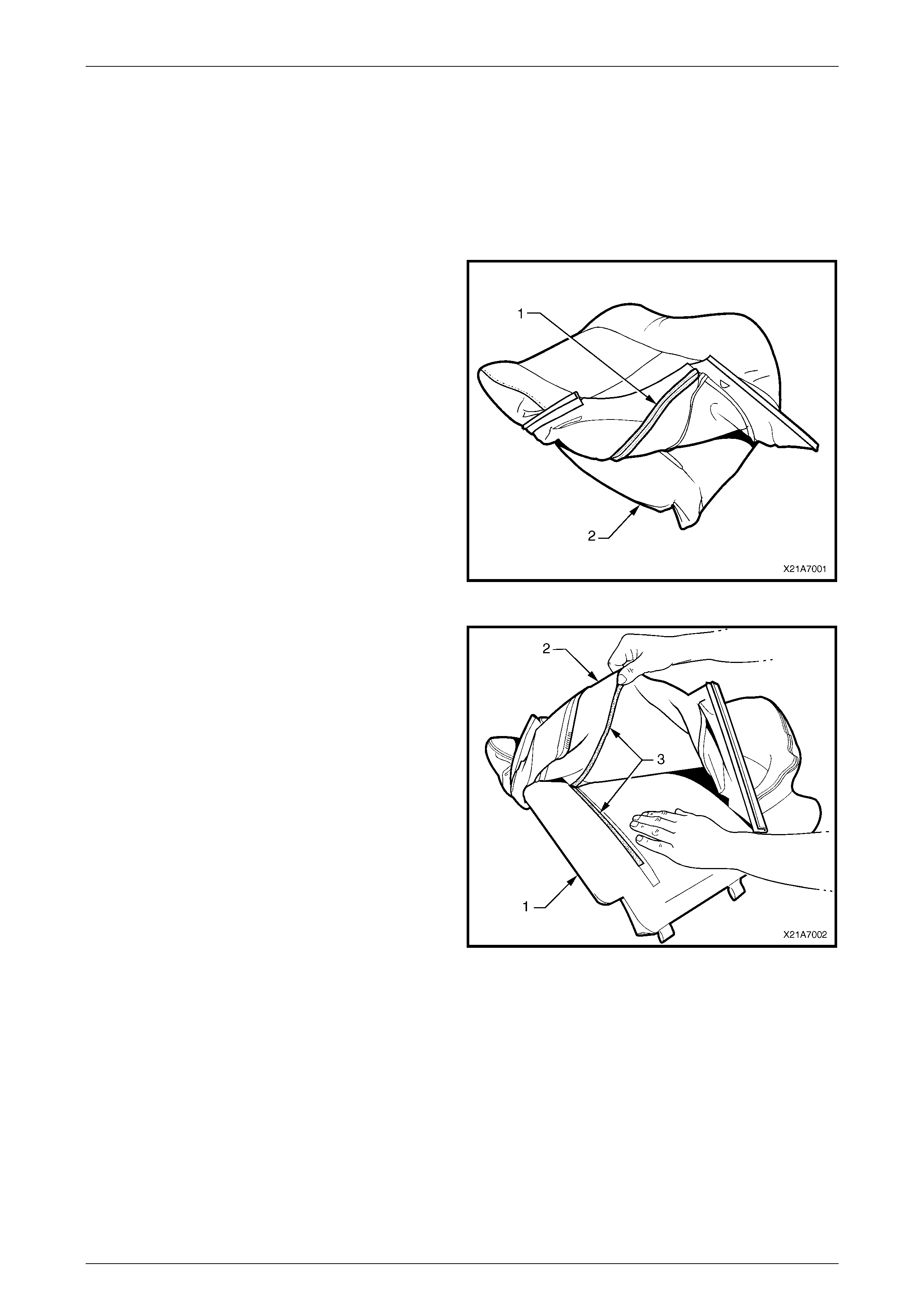
Seat Assemblies Page 1A7–45
Page 1A7–45
Disassemble
NOTE
The following procedure only applies to
vehicles fitted with Type 5 and 6 seats, refer to
2.1 Front Seat Usage Chart. Type 1 – 4 seat-
back cover and pad assemblies cannot be
disassembled.
1 Fold the lower corners of the seat-back cover (1) over
the seat-back pad (2).
Figure 1A74 – 42
2 While holding the front seat-back pad (1), pull the
lower corners of the seat-back cover (2), upwards and
away from the pad to disengage the hook and loop
strips (3).
3 Pull the cover up and over the upper edge of the pad
and remove.
Figure 1A7 – 43
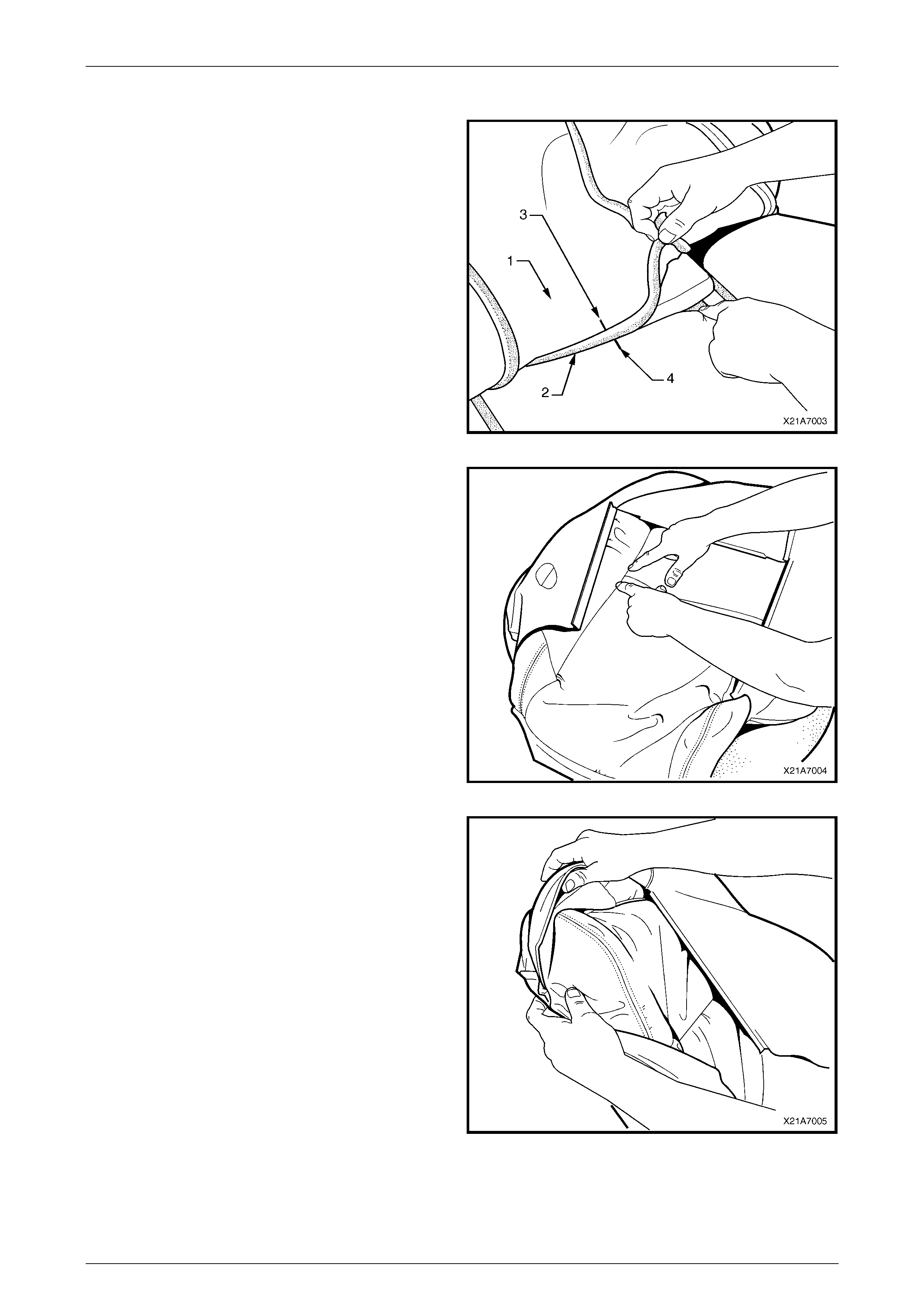
Seat Assemblies Page 1A7–46
Page 1A7–46
Reassemble
1 With the front seat-back cover (1) folded at the central
horizontal strip of hook and loop (2), align the centre
mark (3) on the cover with the centre mark (4) on the
front seat-back pad.
2 Press the cover firmly into the corresponding groove in
the pad to engage the hook and loop.
Figure 1A7 – 44
3 With the fr ont seat- bac k cov er folde d at the two
vertical strips of the hook and loop, press the cover
firmly into the corresponding grooves in the seat-back
pad.
Figure 1A7 – 45
4 Roll the upper corners of the front seat-back cover
over the front seat-back pad.
5 Roll the sides of the cover over the pad.
6 Roll the lower corners of the cover over the seat-back
pad.
NOTE
Make sure the cover is fitted neatly by hand into
all corners and contours of the seat pad.
Figure 1A7 – 46
Reinstall
Reinstallation of the rear seat-back pad and cover assembly is the reverse of the removal procedure.
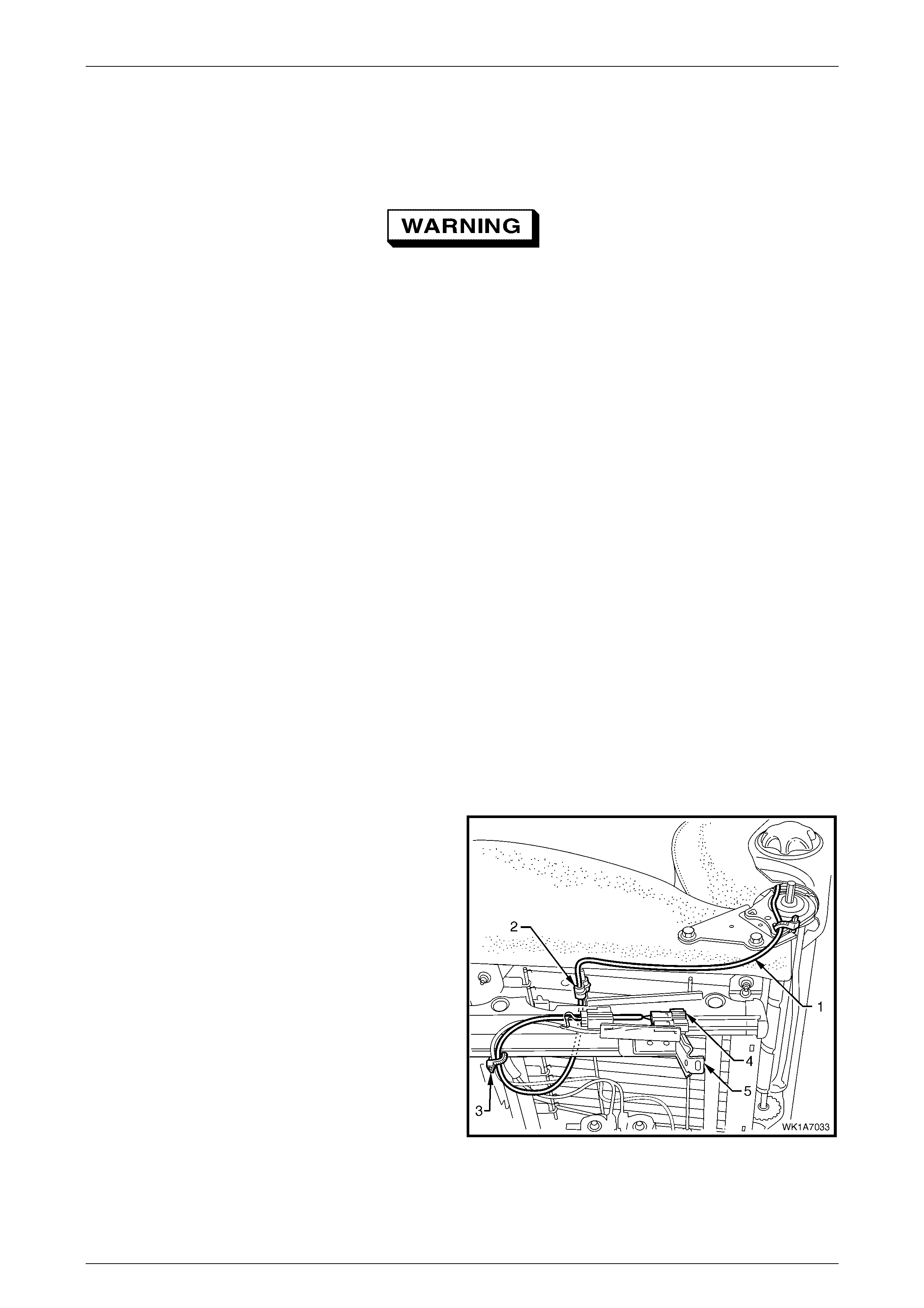
Seat Assemblies Page 1A7–47
Page 1A7–47
2.10 Front Seat-back Frame Assembly
LT Section No. – 14-275
When carrying a live (undeployed) side
impact airbag assembly or a front seat-back
frame assembly fitted with a (undeployed)
side impact airbag assembly, ensure the
airbag opening is pointed away from you.
Never carry the side impact airbag assembly
or seat-back frame assembly fitted with a side
impact airbag assembly by the airbag wiring
harness or connectors. In case of an
accidental deployment, the airbag will then
deploy with minimal chance of injury.
When placing a live side impact airbag
assembly or a front seat-back frame assembly
fitted with a (undeployed) side impact airbag
assembly on a bench or other surface, always
face the airbag opening up, away from the
surface. Never rest the airbag assembly or
seat-back frame with the airbag opening face
down. This is necessary so that a free space
is provided to allow the airbag to expand in
the unlikely event of accidental deployment.
Otherwise, personal injury may result.
As required, remove the following components:
1 Front seat assembly, refer to 2.3 Front Seat Assemb ly.
2 Front seat outer side cover, refer to 2.4 Fron t Seat Outer Side C over A ssemb ly.
3 Front seat inner side cover, refer to 2.5 Front Seat Inner Side Cover.
Remove
1 Where fitted, unclip the side impact airbag wiring
harness (1) from the retaining clip (2) and cut the
cable tie (3) securing the harness to the front seat
cushion frame assembly.
2 Unclip the wiring harness connector (4) from the track
and height adjust assembly (5).
Figure 1A7 – 47

Seat Assemblies Page 1A7–48
Page 1A7–48
3 Remove the screw (1), two places each side, attaching
the front seat-back assembly (2) to the seat cushion
frame assembly (3).
4 Remove the front seat-back assembly.
Figure 1A7 – 48
Disassemble
As required, remove the following components:
1 Front seat-back rear cover assembly, refer to 2.6 Front Seat-back Rear Cover Assembly and Lumber Support Knob
Assembly.
2 Front seat head restraint assembly, refer to 2.7 Front Seat Head Restraint Assembly.
3 Front seat head restraint sleev es, refer to 2.8 Front Seat Head Restraint Sleeve.
4 Front seat-back pad and cover assembly, refer to 2.9 Front Seat-back Pad and Cover Assembly.
Lumbar Support and Adjuster Assembly
Remove
1 From the rear of the front seat-back frame (1),
disengage the clip (2) securing the lumbar support
adjuster cable (3). Squeeze the tangs on the tie clip
together and push the clip through the seat-back
frame.
Figure 1A7 – 49
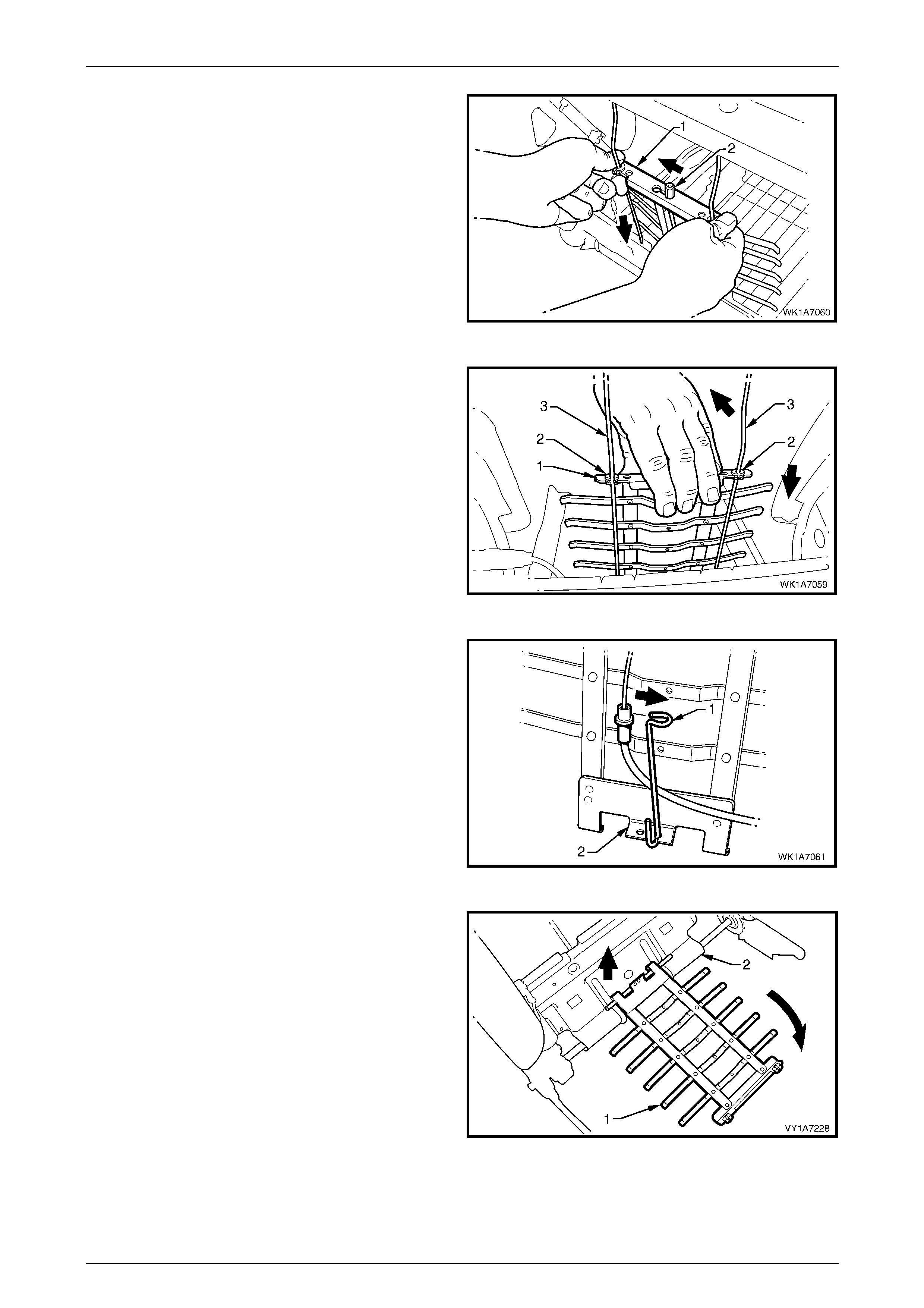
Seat Assemblies Page 1A7–49
Page 1A7–49
2 Slightly compress the lum bar s upport as se mbly (1) by
hand to release the cable (2) tension, disengaging the
cable from the top of the lumbar support assembly.
Figure 1A7 – 50
3 Push down on the top of the lumbar support assembly
(1) to disengage the two retainers (2) from the guide
rails (3), allowing the lumbar s upport as se mbly to
swing freely.
Figure 1A7 – 51
4 Unclip the lower cable retainer (1) from the lower
lumbar bracket (2).
Figure 1A7 – 52
5 Lower the lumbar support assembly (1) until it
becomes disengaged from the seat back frame
assembly (2).
6 Remove the lumbar support assembly
Figure 1A7 – 53
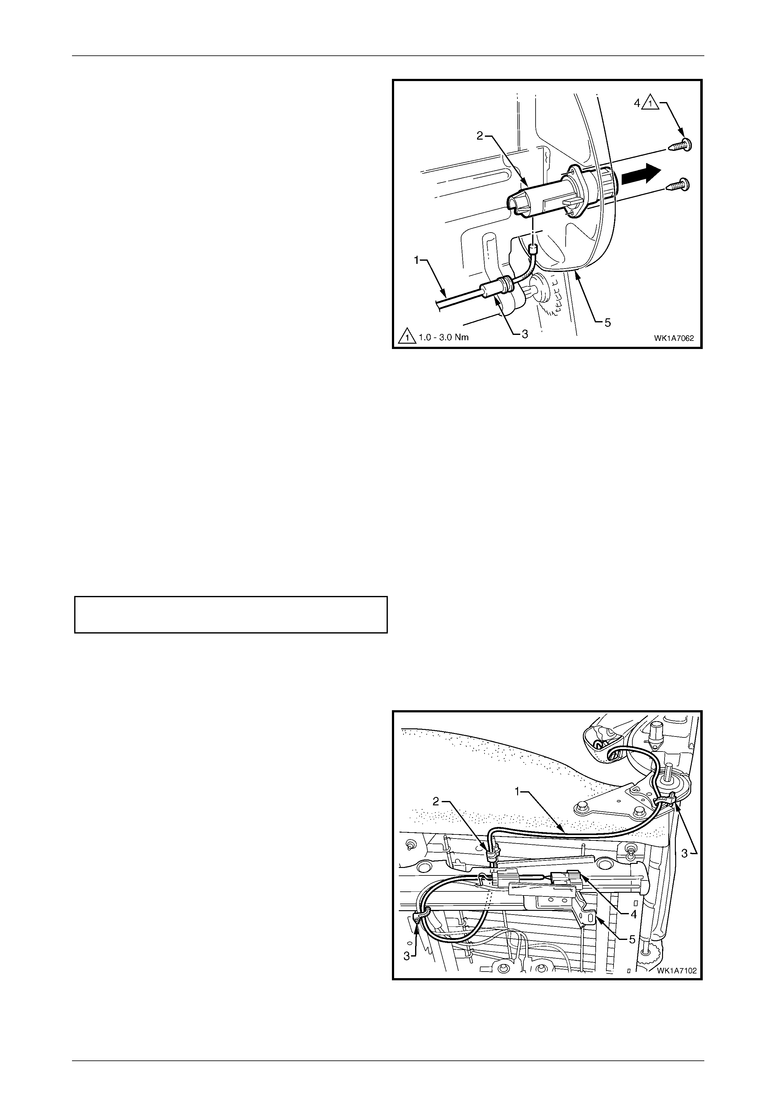
Seat Assemblies Page 1A7–50
Page 1A7–50
7 Remove the adjusting cable (1) from the lumbar
support adjuster (2) by unclipping the outer casing (3)
of the cable from the adjuster and remov e the cabl e.
8 If required, remove the two screws (4) attaching the
lumbar support adjuster to the seat-back frame (5) and
remove the adjuster.
Figure 1A7 – 54
Reins tal l
Reinstallation of the lumbar support and adjuster assembly is the reverse of the removal procedure, noting the following:
1 Align the hole in the lumbar support adjuster for the adjusting cable ball by turning the adjuster, insert the cable into
the adjuster and push the outer casing of the cable into the locking seat of the adjuster until it clicks in place.
NOTE
On the left-hand seat, the cable fits into the
adjuster from the under-side. On the right-hand
seat, the cable fits into the adjuster from the top.
2 Tighten the attaching screws to the correct torque specification.
Lumbar support adjuster attaching
screw torque specification.......................... 1.0 – 3.0 Nm
Side Impact Airbag Assembly
Remove
1 As required, unclip the pigtail wiring harness (1) from
the retaining clip (2) and cut the two cable ties (3),
securing the harness to the front seat cushion fram e
assembly, taking care not to damage the wiring
harness.
2 Unclip the wiring harness connector (4) from the track
and height adjust assembly (5).
Figure 1A7 – 55
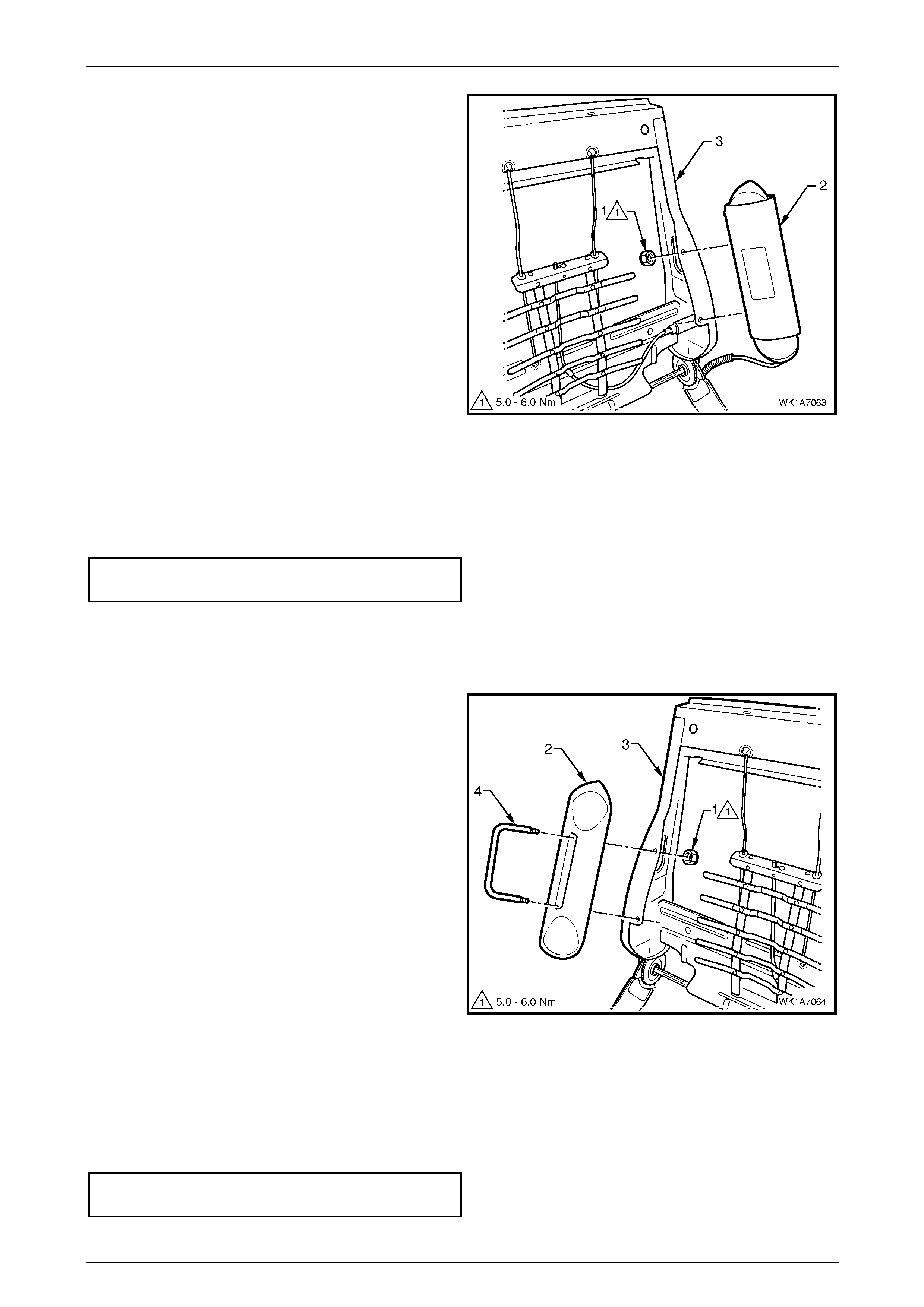
Seat Assemblies Page 1A7–51
Page 1A7–51
3 Remove the nut (1), two places, attaching the side
impact airbag assembly (2) to the front seat-back
frame (3).
4 Remove airbag assembly and pigtail wiring harness
assembly from front seat-back frame.
Figure 1A4 – 56
Reinstall
Reinstallation of the side impact airbag assembly is the reverse of the removal procedure, noting the following:
1 Tighten the attaching nuts to the correct torque specification.
Side impact airbag assembly attaching
nut torque specification .............................. 5.0 – 6.0 Nm
Front Seat Dummy Block Insert Assembly
Remove
1 Remove the nut (1), two places, attaching the front
seat dummy block insert assembly (2) to the seat-back
frame (3) and remove.
2 If required, remove the dummy block U-bolt (4) from
the dummy block insert.
Figure 1A7 – 57
Reinstall
Reinstallation of the front seat dummy block insert assembly is the reverse of the removal procedure, noting the
following:
1 Tighten the attaching nuts to the correct torque specification.
Front seat dummy block insert assembly
attaching nut torque specification............... 5.0 – 6.0 Nm

Seat Assemblies Page 1A7–52
Page 1A7–52
Reinstall
Reinstallation of the front seat-back frame assembly is the reverse of the removal procedure, noting the following:
1 Tighten the attaching screws to the correct torque specification.
Front seat-back frame attaching
screw torque specification...................... 30.0 – 45.0 Nm
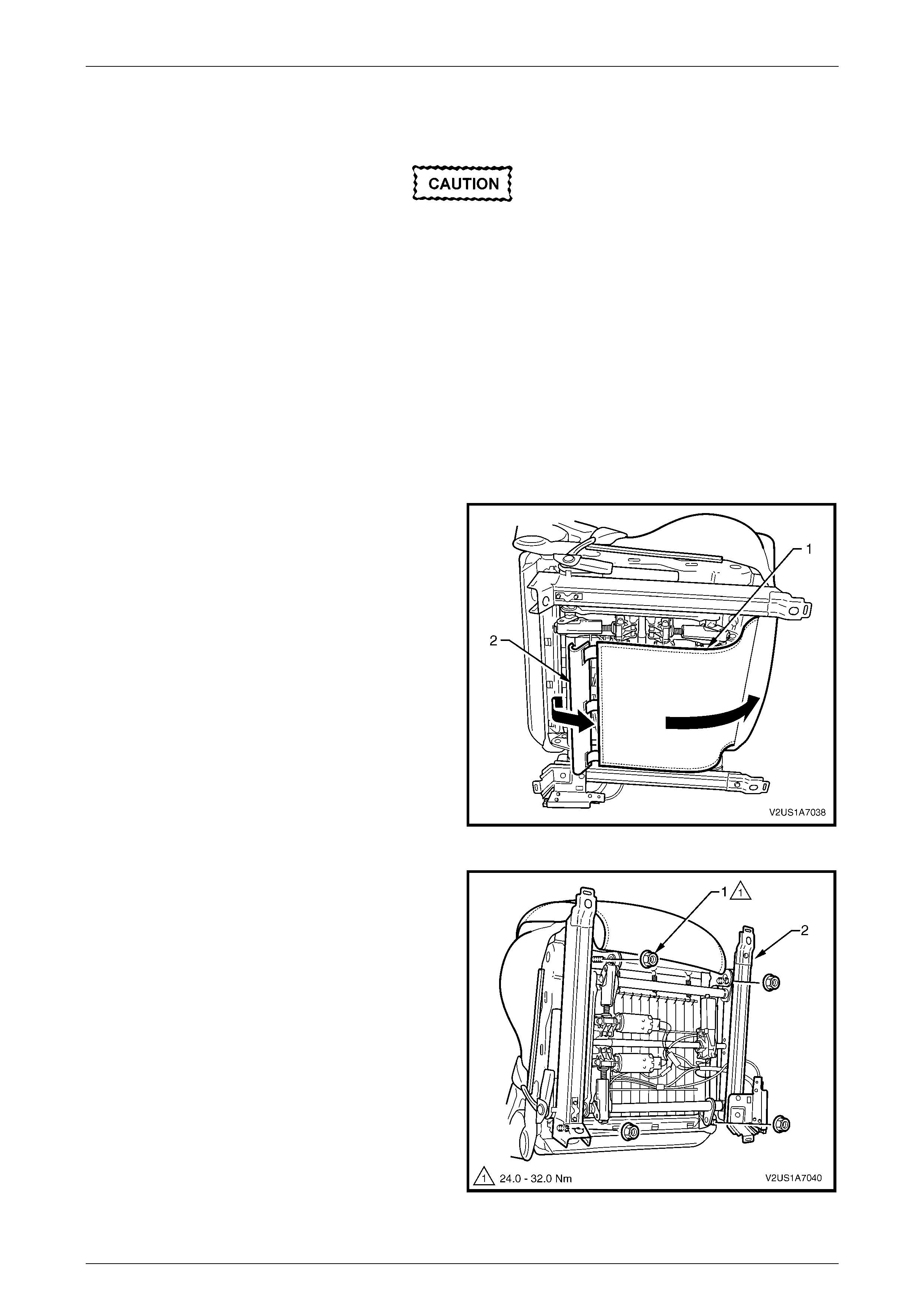
Seat Assemblies Page 1A7–53
Page 1A7–53
2.11 Track and Height Adjust Assembly
The track and height adjust assembly
components are non-serviceable. If the track
and height adjust assembly, drive motors or
drive shafts require replacement, the entire
track and height adjust assembly must be
replaced.
LT Section No. – 14-275
As required, remove the following components:
1 Front seat assembly, refer to 2.23 Fron t Seat Assembly.
2 Front seat outer side cover, refer to 2.4 Fron t Seat Outer Side C over A ssemb ly.
Remove
1 From under the front seat cushion, disconnect the
front seat cushion cover flap (1), by disengaging the J-
strip (2) located on the rear of the flap.
2 Detach the seatbelt pretensioner wiring harness from
the seat cushion frame.
Figure 1A7 – 58
3 Remove the nut (1), four places, attaching the track
and height adjust assembly (2) to the seat.
4 Remove the track and height adjust assembly.
5 If required, remove the seatbelt buckle and
pretensioner assembly, refer to Section 12M ,
2 Service Operations – Seatbelts.
Figure 1A7 – 59

Seat Assemblies Page 1A7–54
Page 1A7–54
Reinstall
Reinstallation of the track and height adjust assembly is the reverse of the removal procedure, noting the following:
1 Ensure the connectors are correctly routed and atta ched securely .
2 Tighten the nuts to the correct torque specification.
Track and height adjust assembly
attaching nut torque specification........... 24.0 – 32.0 Nm
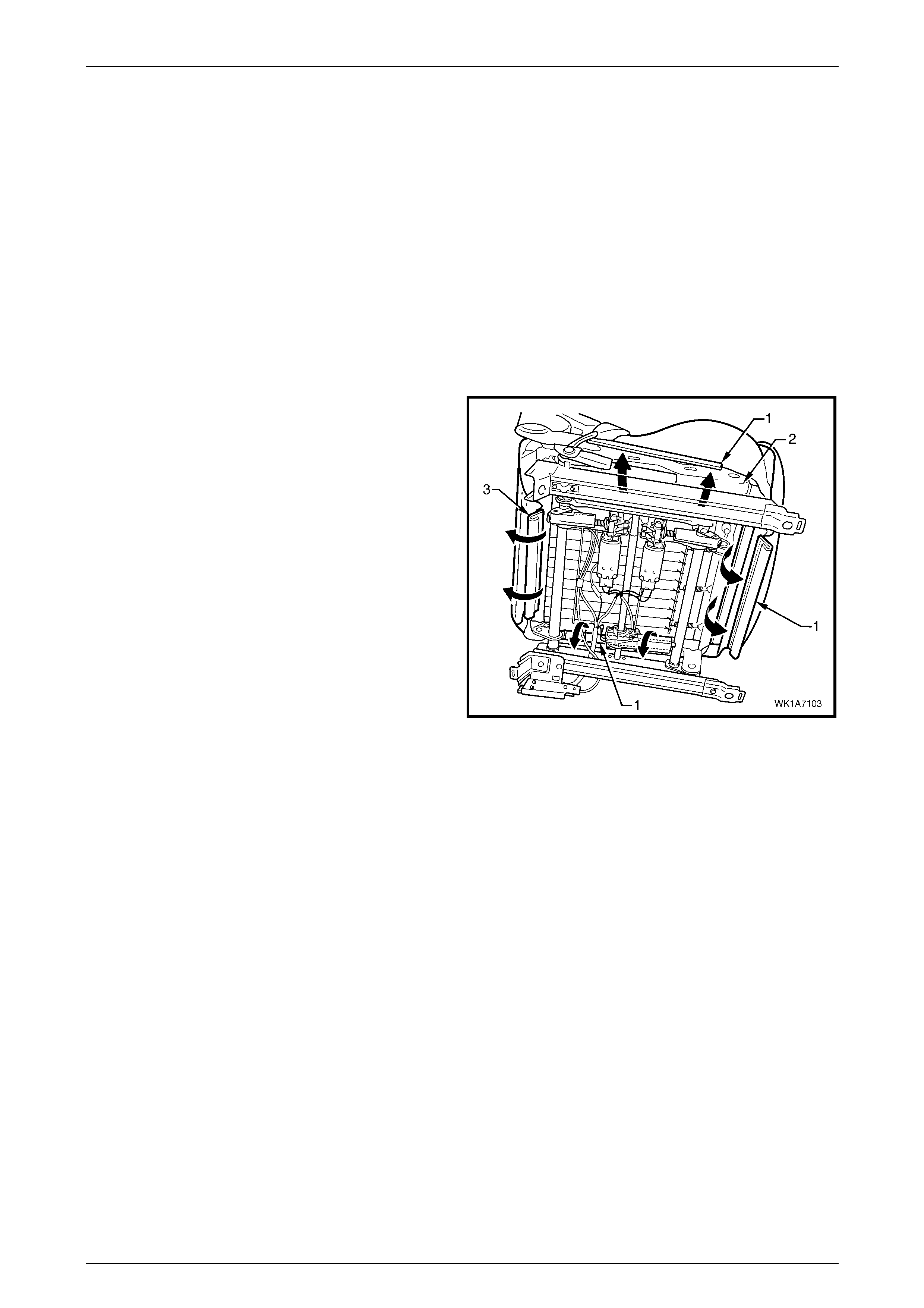
Seat Assemblies Page 1A7–55
Page 1A7–55
2.12 Front Seat Cushion Pad and Cover
Assembly
LT Section No. – 14-295
As required, remove the following components:
1 Front seat assembly, refer to 2.3 Front Seat Assemb ly.
2 Front seat outer side cover, refer to 2.4 Fron t Seat Outer Side C over A ssemb ly.
3 Font seat inner side cover, refer to 2.5 Front Seat Inner Side Cover.
4 Front seat-back frame assembly, refer to 2 .10 F ront Seat-back Frame Assembl y.
Remove
1 From under the front seat cushion, disengage the front
and side J-strips (1) away from the seat frame (2).
2 Lift the cover and pad assembly away from the seat
frame and then release the rear J-strip (3).
3 Remove the cover and pad assembly.
Figure 1A7 – 60
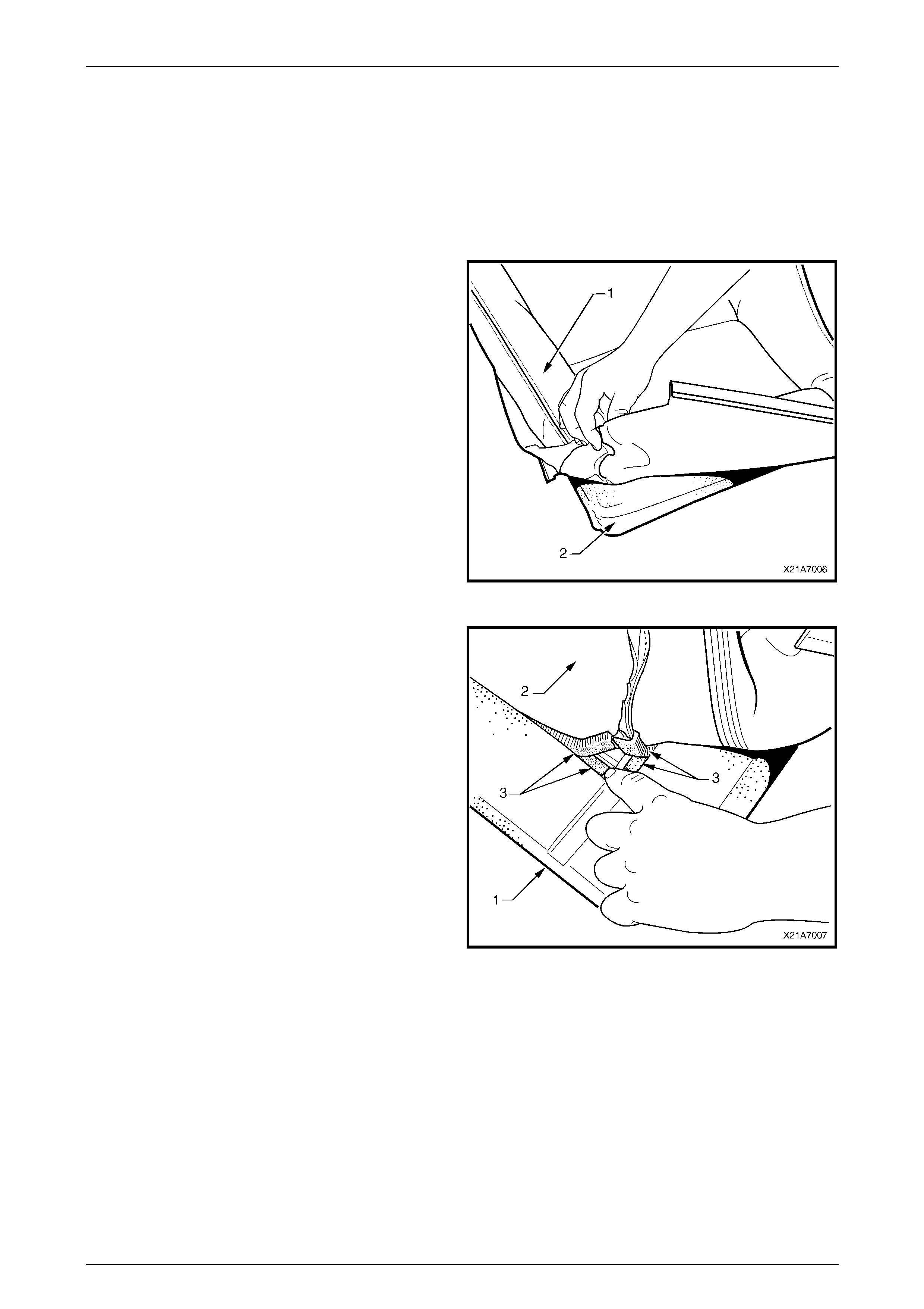
Seat Assemblies Page 1A7–56
Page 1A7–56
Disassemble
NOTE
The following procedure only applies to
vehicles fitted with Type 5 and 6 seats, refer to
2.1 Front Seat Usage Chart. Type 1 – 4 seat
cushion cover and pad assemblies cannot be
disassembled.
1 Fold the rear corners of the front seat cushion cover
(1) over the seat cushion pad (2).
Figure 1A7 – 61
2 While holding the front seat cushion pad (1), pull the
rear corners of the seat cushion cover (2) forward and
away from the front seat cushion pad to disengage the
hook and loop strips (3).
3 Pull the front seat cover up and over the forward edge
of the front seat cushion pad and remove.
Figure 1A7 – 62
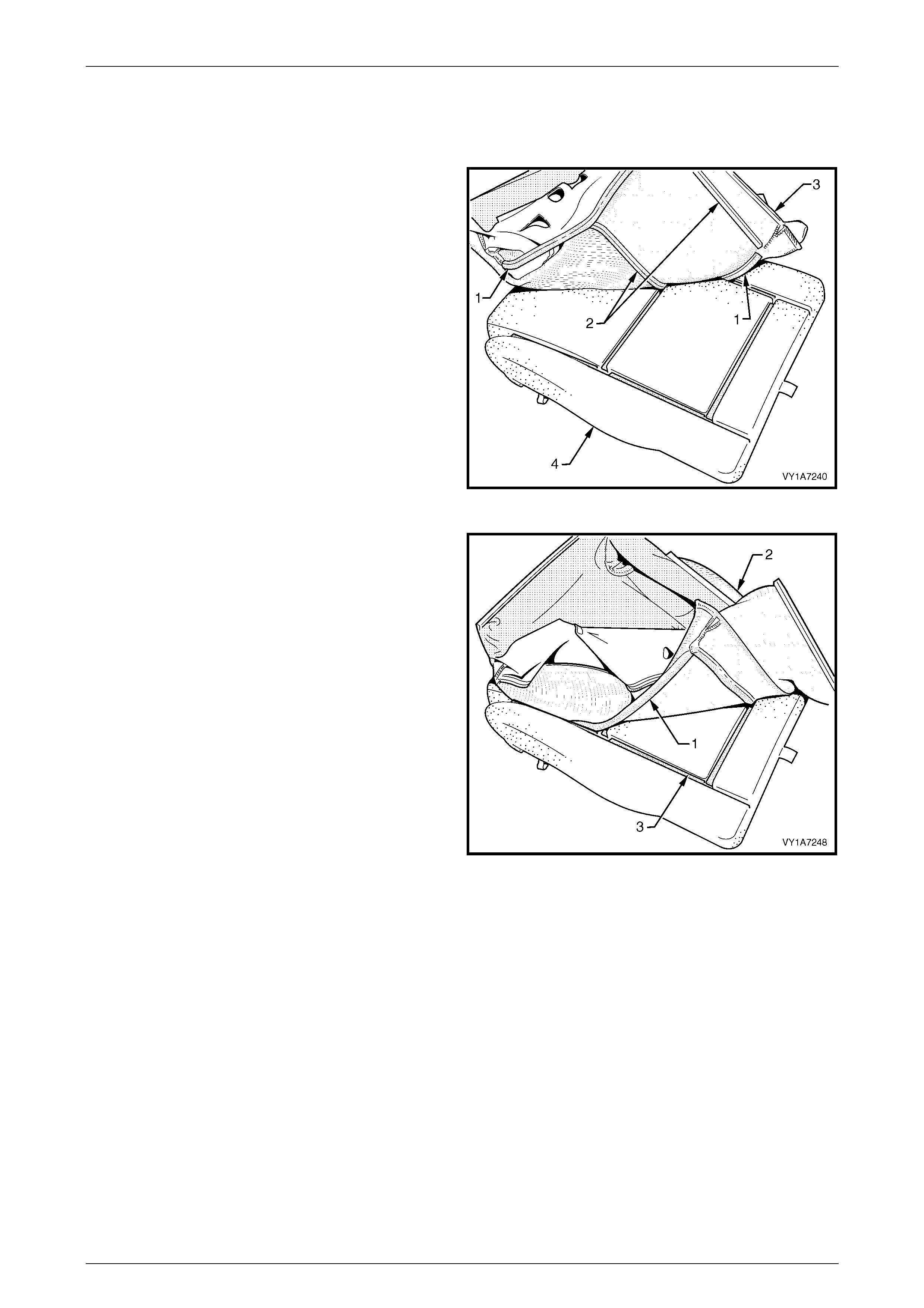
Seat Assemblies Page 1A7–57
Page 1A7–57
Reassemble
Reassembly of the front seat cushion is the reverse of the disassembly procedure noting the following:
1 Align either of the outer hook and loop strips (1) and
the one or two cross hook and loop strips (2), on the
seat cushion cover (3), with the seat cushion pad (4).
2 Press the folded edge of the rear seat cushion cover
firmly into the corresponding groove in the seat
cushion pad to engage the hook and loop strip.
Figure 1A7 – 63
3 Continue aligning and pressing the outer hook and
loop strips (1) on the seat cushion cover (2), wi th the
corresponding groove in the seat cushion pad (3).
Figure 1A7 – 64
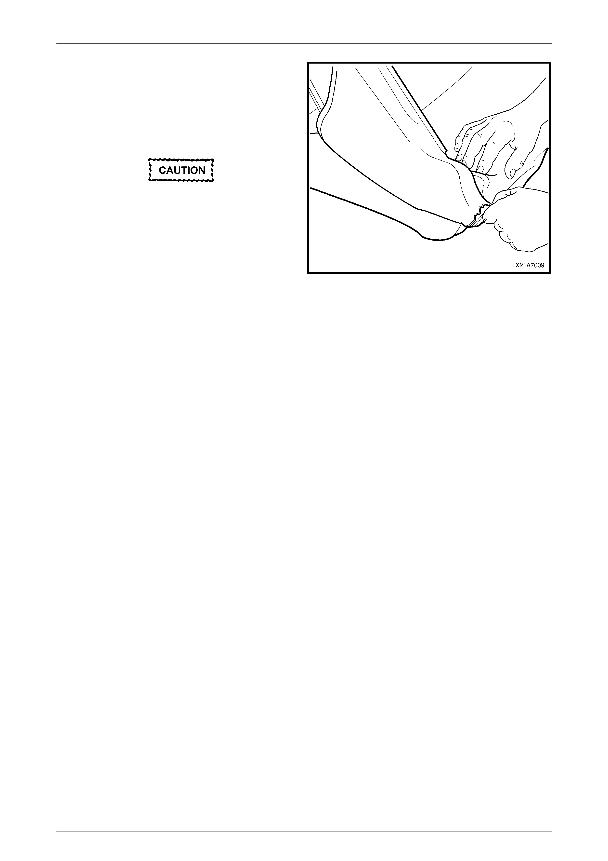
Seat Assemblies Page 1A7–58
Page 1A7–58
4 Roll the front corners of the front seat cushion cover
over the seat cushion pad.
5 Roll the sides of the seat cushion cover over the seat
cu shion pad.
6 Roll the rear corners of the seat cushion cover over
the seat cushion pad.
Do not pull the cover onto the pad from
underneath using the J-strip to make it fit
neatly, as the fabric may be damaged.
NOTE
Make sure the pad is fitted neatly by hand into all
corners and contours of the seat cover.
Figure 1A7 – 65
Reinstall
Reinstallation of the front seat cushion pad and cover assembly is the reverse of the removal procedure.
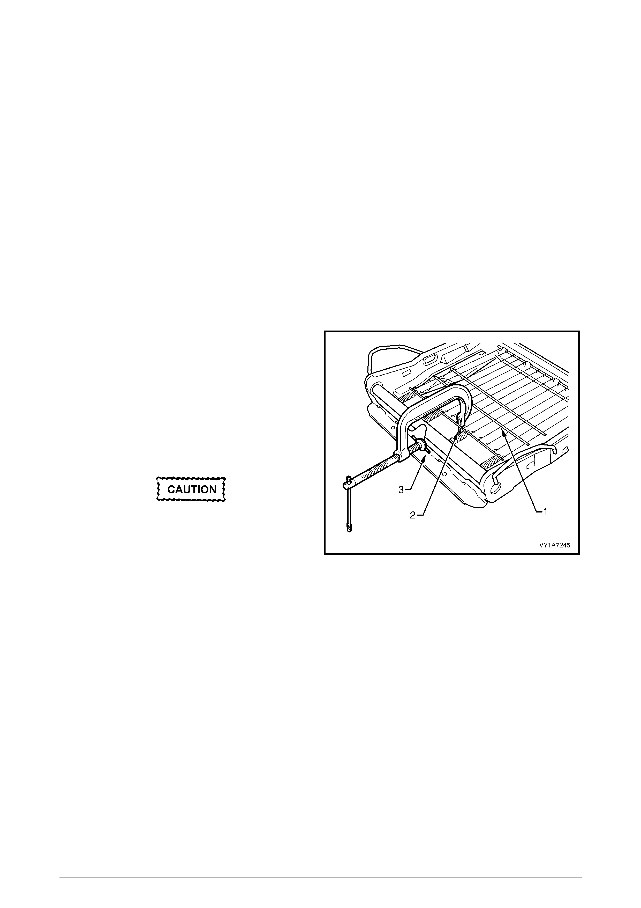
Seat Assemblies Page 1A7–59
Page 1A7–59
2.13 Front Seat Cushion Frame Assembly
LT Section No. – 14-275
Remove
As required remove the following components:
1 Front seat assembly, refer to 2.3 Front Seat Assemb ly.
2 Front seat outer side cover, refer to 2.4 Fron t Seat Outer Side C over A ssemb ly.
3 Front seat inner side cover, refer to 2.5 Front Seat Inner Side Cover.
4 Front seat-back frame assembly, refer to 2 .10 F ront Seat-back Frame Assembl y.
5 Track and height adjust assembly, refer to 2.11 Track and Height Adjust Assembly.
6 Front seat cushion pad and cover assembly, refer to 2.12 Front Seat Cushion Pad and Cover Assembly.
Disassemble
1 To remove the suspension mat (1), modify a G-clamp
with a 5mm diameter metal dowel (2) welded to one
end, approximately 40mm long and with a 2mm
diameter pin (3) approximately 20mm long welded to
the other end.
2 Using the G-clamp, stretch the suspension mat far
enough to allow for the retaining springs to be
removed from the seat cush io n frame.
3 Back the G-clamp load off and remove the suspension
mat.
When using the G-clamp, use existing holes
in the suspension mat to ensure that mat
deformation does not occur.
Figure 1A7 – 66
Reassemble
Reassembly of the suspension mat is the reverse of the removal procedure.
Reinstall
Reinstallation of the front seat cushion frame assembly is the reverse of removal, noting the following:
1 Ensure all wiring is correctly connected and routed, refer to Section 120, Fuses, Relays and Wiring Harnesses.
2 Check the mechanical and electrical operation of the front seat.

Seat Assemblies Page 1A7–60
Page 1A7–60
2.14 Front Seat Lift Motor Assemblies
The front seat lift motor assemblies are non-servic eable items.
If a front seat lift motor assembly requires replacement, the track and height adjust assembly must be replaced, refer to
2.11 Track and Height Adjust Assembly.

Seat Assemblies Page 1A7–61
Page 1A7–61
2.15 Front Seat Fore/Aft Movement Motor
Assembly
The front seat fore/aft movement motor assembly is a non-serviceable item.
If the front seat fore/aft movement motor assembly or drive sh afts require replacem ent, the track and height adjust
assembly must be replaced, refer to 2.11 Track and Height Adjust Assembly.

Seat Assemblies Page 1A7–62
Page 1A7–62
2.16 Front Seat-back Recline Motor Assembl y
The front seat-back recline motor assembly is a non-serviceable item.
If the front seat-back recline motor assembly requires replacement, the front seat-back frame assembly must be
replaced, refer to 2.10 Front Seat-back Frame Asse mbly .

Seat Assemblies Page 1A7–63
Page 1A7–63
3 Diagnostics – Front Seat,
Level 1 and 3
This Section provides charts to assist in the diagnosis and repair of front seats. Refer to 2.1 Front Seat Usage Chart,
Level 1 and 3, for a full listing of the different types of seats fitted to vehicles. Included in that Section are illustrated parts
breakdowns of the various seats.
3.1 Prerequisites
Safety Requirements
When operating the seat as part of any of the Steps in the diagnosis charts, ensure that fingers and limbs are clear of
moving parts.
Equipment
The followi ng equipment is required to diagnose the seats:
1 An unpowered test lamp with a current draw of less than 3 A.
2 A digital multimeter with a minimum impedance of 10 MΩ.
Testing Procedures
The following points must be adhered to when performing diagnostic testing on components:
1 Care must be taken when using testing equipment to diagnose wiring harness connectors. It is preferred that the
technician bac k probe the connector to avoid terminal dama ge.
2 When tests are required on connector terminals, utilise the adapters in the connector adaptor kit KM–609 to
prevent damage to the terminals.
3 Unless the multimeter being us ed has an auto-ranging function, ensure that the correct range is selected.
4 When back-probing connectors, ensure the test lamp ground lead is connected to a suitable ground point on the
vehicle. Ensure that this ground point is not part of the circuit being tested.
NOTE
When following the Steps in the diagnosis charts,
the exact order of Steps should be observed. If
the required nominal value or result is not
achieved at any stage, the problem must be
rectified before proceeding any further.

Seat Assemblies Page 1A7–64
Page 1A7–64
3.2 Mechanical Diagnosis
Lumbar Support Inoperative
Introduction
This test is used by the technician to aid in the diagnosis of the lumbar support assembly.
Test Description
The following numbers refer to the Step numbers in the diagnostic chart.
1 Checks that the lumbar support knob is properly engaging the lumbar support adjuster. Check the knob for cracks
and worn splines.
2 Checks that the lumbar support adjuster is not damaged or worn and that there is correct operation of the adjuster
when the splined shaft is turned throughout its range.
3 Checks that the lumbar support adjuster cable is not broken or binding and is not inhibiting the movement and
travel of the lumbar support as sembly .
4 Checks that the lumbar support assembly is not cracked or bent. If this is the case, it may cause the assembly to
deform and bind on the guide rails.
5 Checks that the guide rails are not cracked or bent. If this is the case, they may cause the lumbar support assembly
to bind.
Step Action Yes No
1 1 Remove the lumbar support knob, refer to
2.6 Front Seat-back Rear Cover Assembly
and Lumbar Support Knob Assembly.
Is the lumbar support adjust knob serviceable? Go to Step 2.
Replace the knob.
Refer to 2.6 Front Seat-back
Rear Cover Assembly and
Lumbar Support Knob
Assembly.
2 1 Remove the front seat-back rear cover
assembly, refer to 2.6 Front Seat-back
Rear Cover Assembly and Lumbar Support
Knob Assembly.
2 Disconnect the lumbar support adjuster
cable from the adjuster, refer to 2.10
Front Seat-back Frame Assembly.
3 Turn the adjuster and check for correct
operation.
Is the lumbar support adjuster serviceable?
Go to Step 3.
Replace the lumbar support
adjuster.
Refer to 2.10 Front Seat-back
Frame Assemb ly.
3 1 Visually inspect the lumbar support
adjuster cable.
Is the lumbar support adjuster cable
serviceable?
Go to Step 4.
Replace the lumbar support
adjuster cab le.
Refer to 2.10 Front Seat-back
Frame Assemb ly.
4 1 Visually inspect the lumbar support
assembly.
Is the lumbar support assembly serviceable? Go to Step 5.
Replace the lumbar support
assembly.
Refer to 2.10 Front Seat-back
Frame Assemb ly.
5 1 Visually inspect the lumbar support
assembly guide rails.
Are the lumbar support assembly guide rails
serviceable?
System servic eabl e.
Replace the front seat-back
frame assembly .
Refer to 2.10 Front Seat-back
Frame Assemb ly.
When all diagnosis and repairs are completed, check the system for correct operation.

Seat Assemblies Page 1A7–65
Page 1A7–65
Four-way/Six-way Seat-back Recline Forward and/or Aft Function is Inoperative
Introduction
This test is used by the technician to aid in the diagnosis of the recline function of the seat assembly.
Test Description
The following numbers refer to the Step numbers in the diagnostic chart.
1 Checks that the recliner knob is properly engaging the recliner shaft. Check the knob for cracks and worn splines.
Step Action Yes No
1 1 Remove the recliner kn ob, refer to
2.4 Front Seat Outer Side Cover
Assembly.
Is the recliner knob serviceable?
Replace the front seat-back
frame assembly .
Refer to 2.10 Front Seat-back
Frame Assembly.
Replace the recliner knob.
Refer to 2.4 Front Seat Outer
Side Cover Assembly.
When all diagnosis and repairs are completed, check the system for correct operation.
Four-way Seat Fore/Aft M ovement Function is Inoperative or is Not Smooth
Introduction
This test is used by the technician to aid in the diagnosis of the fore/aft movement function of the seat being inoperative
or the action of the seat through the range of movement is not smooth.
Test Description
The following numbers refer to the Step numbers in the diagnostic chart.
1 Checks that there are no items obstructing the guide rails which may stop or hinder the seat movement.
2 Checks that the guide rails have adequate lubricant applied to provide a smooth operation for the seat.
3 Checks that the linkage assembly between the adjustment lever and lock ing tangs is not worn or damaged. The
locking tangs must disengage from the guide rails before the seat will move.
4 Checks that the guide rails have not been damaged. Any binding between the inner and outer guide rails will result
in poor operation of the fore and aft movement.
Step Action Yes No
1 Are the guide rails free from obstructions? Go to Step 2. Remove the obstructing item.
2 Are the guide rails adequately lubricated?
Go to Step 3.
Apply a small amount of
grease type NLGI No. 1
Lithium Grease (with 9% Zinc
Oxide) to the rails.
3 Do the locking tangs disengage the guide rails
when the seat fore and aft adjustment lever is
raised to its full movement? Go to Step 4.
Replace the front seat track
and height adjust assembly.
Refer to 2.11 Track and
Height Adjust Assembly.
4 Do the guide rails bind at any point of travel
during the fore and aft movements of the seat? Replace the front seat track
and height adjust assembly.
Refer to 2.11 Track and
Height Adjust Assembly.
System servic eabl e.
When all diagnosis and repairs are completed, check the system for correct operation.

Seat Assemblies Page 1A7–66
Page 1A7–66
3.3 Electrical Diagnosis – Four-way/Six-way
Seat
The charts in this Section are used by the technician in the aid of diagnosing faults on four-way and six-way seat
assemblies. To aid in the use of the diagnosis charts, refer to Wiring Diagram – Four-way/Six-way Seat and Connector
Chart – Four-way/Six-way Seat in this Section.
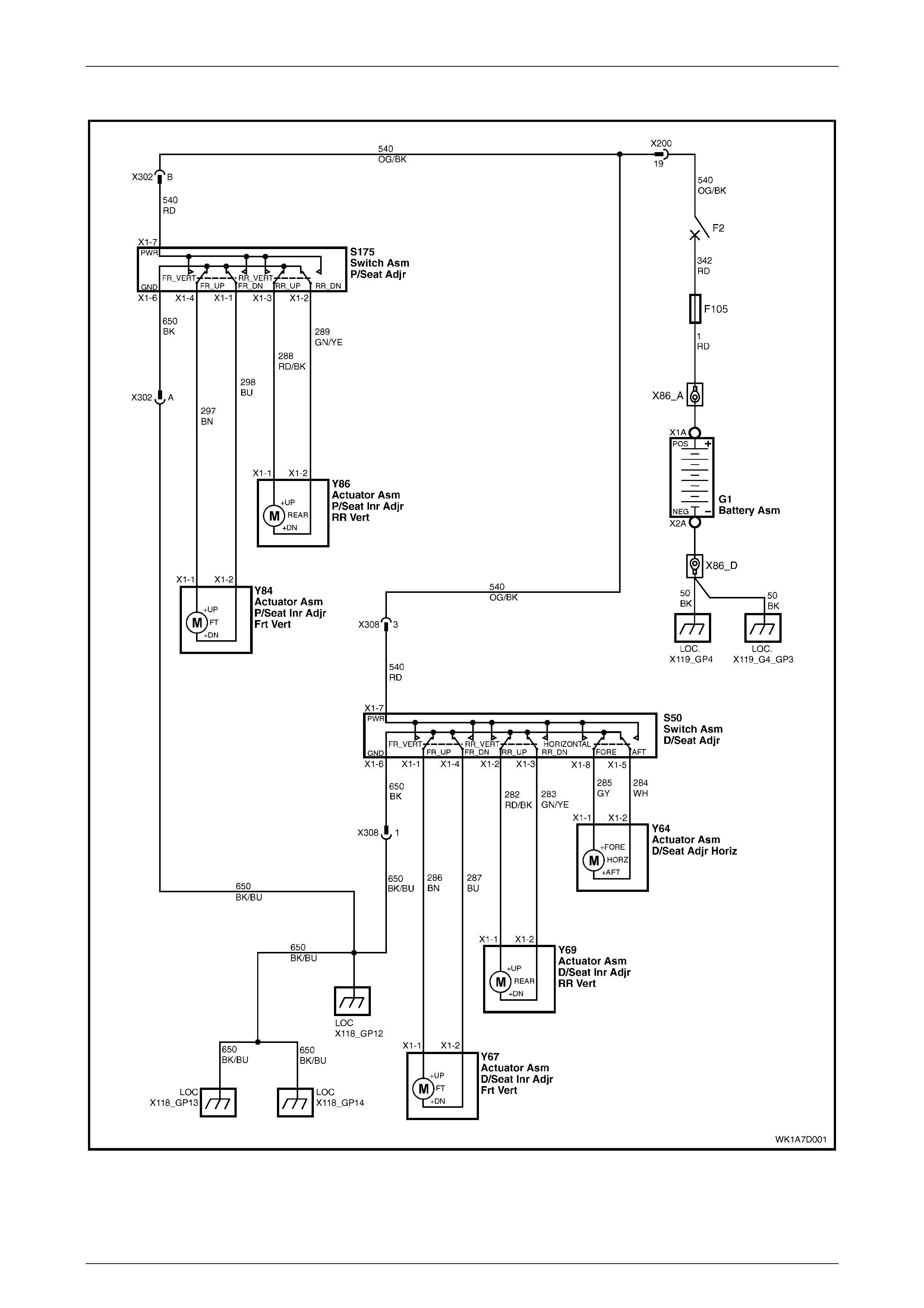
Seat Assemblies Page 1A7–67
Page 1A7–67
Wiring Diagram – Four-way/Six-way Seat
Figure 1A7 – 67
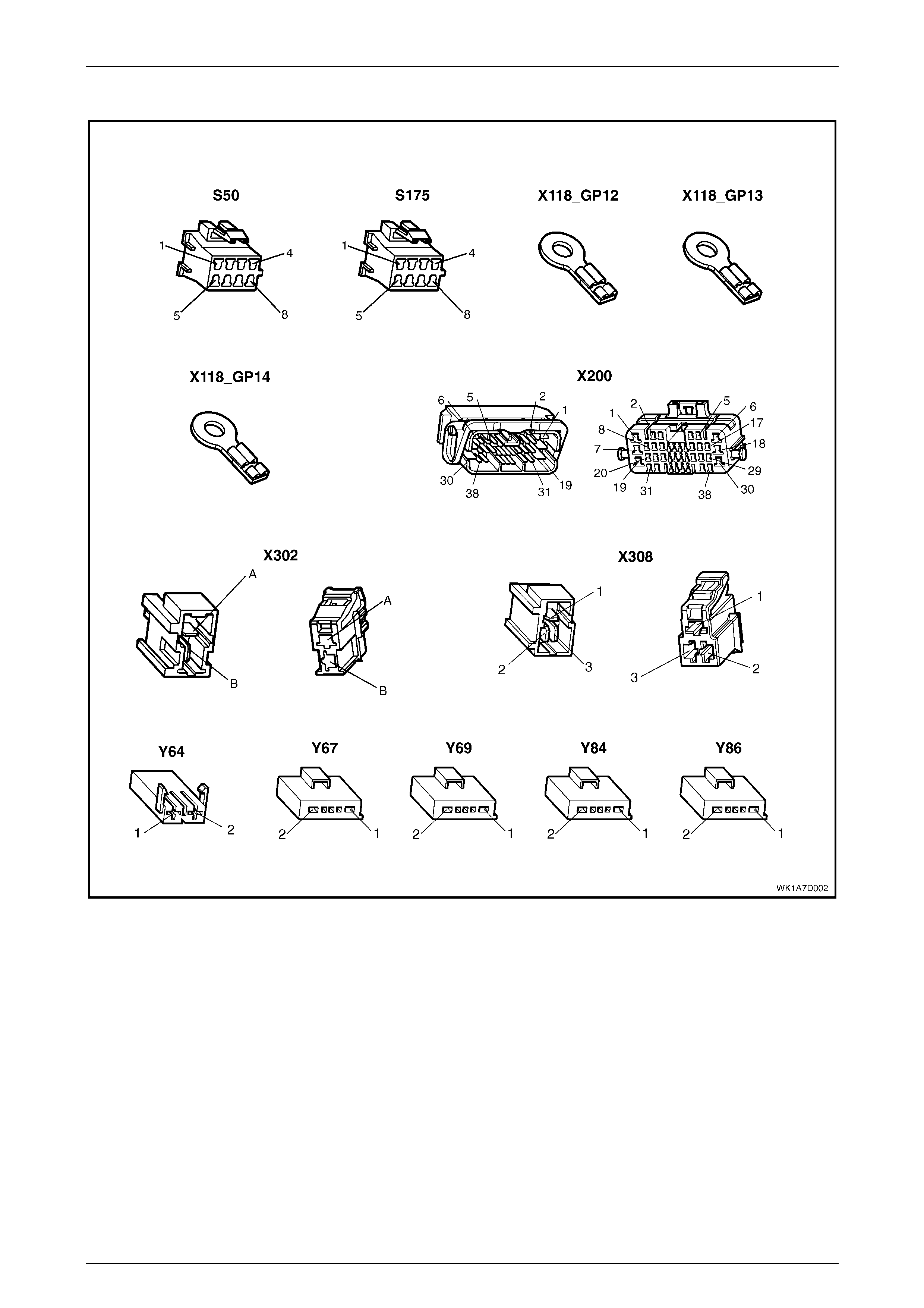
Seat Assemblies Page 1A7–68
Page 1A7–68
Connector Chart – Four-way/Six-way Seat
Figure 1A7 – 68

Seat Assemblies Page 1A7–69
Page 1A7–69
Neither Seat Adjustment Switch Functions Operate
Introduction
This test is used by the technician to aid in the diagnosis of the seat power and ground circuits, if neither seat operates
when either seat adjustment switch is operated.
Test Description
The following numbers refer to the Step numbers in the diagnostic chart.
1 Checks that battery voltage is more than 11.5 volts. The seat motors require more than 11.5 volts to operate
correctly.
2 Checks that circuit breaker F2 located on the passenger compartment fuse and relay panel assembly is not tripped.
Isolates whether circuit breaker F2 is the fault affecting the circuit between the battery and connector X200 pin 19.
3 Checks that fusible link F105 located on the engine compartment fuse and relay panel assembly is serviceable.
Isolates whether the fusible link is the fault affecting the circuit between the battery and connector X200 pin 19.
4 Ensures that connector X200 is secure.
5 Checks whether there is battery voltage at connector X200 pin 19. Isolates whether the fault is be tween the battery
and connector X200 pin 19. If the fault in the circuit is between connectors X200 pin 19 and either X308 pin 3 or
X302 pin B, only one seat will not operate.
6 Checks whether there is battery voltage at circuit breaker F2. Isolates whether the fault is between the battery and
circuit breaker F2 or between circuit breaker F2 and connector X200 pin 19.
7 Checks whether there is battery voltage at fusible link F105. Isolates whether the fault is between the battery and
fusible link F105 or between fusible link F105 and circuit breaker F2.
8 Checks that all the ground points associated with the system are serviceable and a good ground is provided at
each point.
Step Action Yes No
1 1 Check the battery voltage, refer to Section
12A, 2.9 Battery.
Is the battery voltage more than 11.5 V? Go to Step 2. Refer to Section 12A, 2.9
Battery for further diagnosis.
2 1 Inspect circuit breaker F2, refer to Section
12O, 2.2 Circuit Breakers.
Is circuit breaker F2 tripped?
Allow the circuit breaker to
reset, refer to Section 12O,
2.2 Circuit Breakers. Go to Step 3.
3 1 Inspect fusible link F105, refer to Section
12O, 2.3 Fusible Links.
Is fuse F105 serviceable? Go to Step 4. Replace the fusible link.
4 Is connector X200 secure? Go to Step 5. Ensure that the connector is
secure.
5 1 Back probe connector X200 pin 19 with a
test lamp.
Does the test lamp illuminate? Go to Step 8. Go to Step 6.
6 1 Remove circuit breaker F2 from the
passenger comp artm ent fus e and relay
panel assembly.
2 Using a test lamp, probe connector
X129 - X4 5 – 2. Refer to Section 12P
Wiring Diagrams.
Does the test lamp illuminate?
There is a fault in circuit 540
between circ uit breaker F2 and
connector X200 pin 19.
Repair or replace circuit 540.
Go to Step 7.

Seat Assemblies Page 1A7–70
Page 1A7–70
Step Action Yes No
7 1 Remove fusible link F105.
2 Using a test lamp, probe connector
X18-105. Refer to Section 12P Wiring
Diagrams.
Does the test lamp illuminate?
There is a fault in circuit 342
between fusible link F105 and
circuit breaker F2.
Repair or replace circuit 342.
There is a fault in circuit 1
between the battery and
fusible link F105.
Repair or replace circuit 1.
8 1 Ensure that the following ground points are
secure and have good contact with the
vehicle structure:
• X118–GP12 located in the middle of
the transmission tunnel.
• X118–GP13 located in the rear
compartment on the right-hand side
tail lamp stud.
• X118–GP14 located on the rear
compartment lid .
Refer to Section 12P Wiring Diagrams for further
details of ground ing poi nts.
Are all the ground points secure to the vehicle
with a good contact?
There is a fault in circuit 650.
Repair or replace circuit 650.
Ensure that the connectors are
secured to the vehicle and that
there is a good contact
between the conne ctor and th e
vehicle.
When all diagnosis and repairs are completed, check the system for correct operation.

Seat Assemblies Page 1A7–71
Page 1A7–71
None of the Driver’s Seat Adjustment Switch Functi ons Operate
Introduction
This test is used by the technician to aid in the diagnosis of the driver’s seat adjustment switch when none of the switch
functions operate. The test diagnoses the driver’s seat adjustment switch and associated power and ground circuits.
Test Description
The following numbers refer to the Step numbers in the diagnostic chart.
1 Checks whether all of the passenger's seat functions work. If none of them work, the fault is not isolated to the
driver’s seat only .
2 Checks whether there is battery power at connector X308 pin 3. Isolates whether there is a fault in circuit 540
between connectors X200 pin 19 and X308 pin 3.
3 Checks that all the connectors required for the seat to operate effectively are in place and positively connected.
4 Checks whether there is battery power at connector S50 – X1 pin 7. Isolates whether there is a fault in circuit 540
between connectors S50 – X1 pin 7 and X308 pin 3.
5 Checks whether the driver’s seat adjustment switch is serviceable.
5 Checks whether there is continuity between connectors S50 – X1 pin 6 and X308 pin 1 which supplies the ground
circuit for the driver’s seat adjustment switch. Isolates whether there is a fault in circuit 650 between the switch and
connector X308 pin 1 or between connector X308 pin 1 and the grounding points.
Step Action Yes No
1 Are all of the passenger’s seat adjustment switch
functions inoperative? Refer to Neither Seat
Adjustment Switc h Functions
Operate in this Section. Go to Step 2.
2 1 Back probe connector X308 pin 3 with a
test lamp.
Does the test lamp illuminate? Go to Step 3.
There is a fault in circuit 540
between connectors
X200 pin 19 and X308 pin 3.
Repair or repl ace circuit 540.
3 Are the following connectors secure?
• S50
• X308
• Y64
• Y67
• Y69
Go to Step 4. Ensure that the connectors are
secure.
4 1 Back probe connector S50 – X1 pin 7 with
a test lamp.
Does the test lamp illuminate? Go to Step 5.
There is a fault in circuit 540
between connectors
S50 – X1 pin 7 and X308 pin 3.
Repair or repl ace circuit 540.
5 1 Remove the driver’s seat adjustment
switch from the seat, re fer to 2.4 Front
Seat Outer Side Cover Assembly.
2 Test the driver’s seat adjustment switch,
refer to 3.5 Six-way Seat Adjustment
Switch Test.
Is the driver’s seat adjustment switch
serviceable?
Go to Step 6.
Replace the driver’s seat
adjustment switch.
Refer to 2.4 Front Seat Outer
Side Cover Assembly.
6 1 Back probe connector X308 pin 1 with a
test lamp.
2 Operate the driver’s seat adjustment switch
in any of the available directions.
Does the test lamp illuminate?
There is a fault in circuit 650
between connector X308 pin 1
and ground points X118-GP12,
X118–GP13 and X118–GP14.
Repair or replace circuit 650.
There is a fault in circuit 650
between connectors
S50 – X1 pin 6 and X308 pin 1.
Repair or repl ace circuit 650.
When all diagnosis and repairs are completed, check the system for correct operation.

Seat Assemblies Page 1A7–72
Page 1A7–72
Front/Rear of the Driver's Seat Does Not Raise and/or Lower
Introduction
This test is used by the technician to aid in the diagnosis of the front and/or the rear of the driver's seat not raising and/or
lowering. The test diagnoses the seat adjustment switch and the motor circuits.
Test Description
The following numbers refer to the Step numbers in the diagnostic chart.
1 Checks whether the driver's seat adjustment switch assembly operates the seat in any direction. Isolates whether
there is a battery or ground fault affecting the seat operation.
2 Checks that all the connectors required for the seat to operate effectively are in place and positively connected.
3 Checks whether the driver's seat adjustment switch is serviceable.
4 Confirms whether the rear of the seat raises or lowers. Isolates whether the rear lift motor and circuit of the seat is
the fault.
5 Confirms whether the front of the seat raises or lowers. Isolates whether the front lift motor and circuit of the seat is
the fault.
6 Checks whether there is battery power to the seat rear lift motor at connector Y69 – X1 pin 1. Isolates whether
there is a fault in circuit 282 that supplies battery power to the motor to raise the rear of the seat.
7 Checks whether there is battery power to the seat rear lift motor at connector Y69 – X1 pin 2. Isolates whether the
fault is in circuit 283 that supplies battery power to the motor to lower the rear of the seat or the motor is faulty. As
reversing the polarity changes the direction of the motor, this Step also confirms that the ground circuit from Step 6
is serviceable.
8 Checks whether there is battery power to the seat front lift motor at connector Y67 – X1 pin 1. Isolates whether
there is a fault in circuit 286 that supplies battery power to the motor to raise the front of the seat.
9 Checks whether there is battery power to the seat front lift motor at connector Y67 – X1 pin 2. Isolates whether the
fault is in circuit 287 that supplies battery power to the motor to lower the front of the seat or the motor is faulty. As
reversing the polarity changes the direction of the motor, this Step also confirms that the ground circuit from Step 8
is serviceable.
Step Action Yes No
1 Does the driver's seat adjustment switch operate
the seat correctly in any of the six directions? Go to Step 2.
Refer to None of the Driver’s
Seat Adjustment Switch
Functions Operate in this
Section.
2 Are the following connectors secure?
• S50
• Y67
• Y69
Go to Step 3. Ensure that the connectors are
secure.
3 1 Remove the driver's seat adjustment
switch from the seat, re fer to 2.4 Front
Seat Outer Side Cover Assembly.
2 Test the driver's adjustment switch, refer to
3.5 Six-way Seat Adjustment Switch Test.
Is the driver's seat adjustment switch
serviceable?
Go to Step 4.
Replace the driver's seat
adjustment switch.
Refer to 2.4 Front Seat Outer
Side Cover Assembly.
4 1 Operate the driver's seat adjustment switch
to raise or lower the rear of the seat.
Does the rear of the seat raise and lower? Go to Step 5. Go to Step 6.
5 1 Operate the driver's seat adjustment switch
to raise or lower the front of the seat.
Does the fron t of the seat raise and lower? System serviceable. Go to Step 8.

Seat Assemblies Page 1A7–73
Page 1A7–73
Step Action Yes No
6 1 Back probe connector Y69 – X1 pin 1 with
a test lamp.
2 Operate the driver's seat adjustment switch
to raise the rear of the seat.
Does the test lamp illuminate?
Go to Step 7.
There is a fault in circuit 282
between connectors S50 – X1
pin 2 and Y69 – X1 pin 1.
Repair or repl ace circuit 282.
7 1 Back probe connector Y69 – X1 pin 2 with
a test lamp.
2 Operate the driver's seat adjustment switch
to lower the rear of the seat.
Does the test lamp illuminate?
The seat rear lift motor is
faulty.
Replace the seat rear lift
motor, refer to 2.14 Front Seat
Lift Motor Assemblies.
Go to Step 5.
There is a fault in circuit 283
between connectors
S50 – X1 pin 3 and
Y69 – X1 pin 2.
Repair or repl ace circuit 283.
Go to Step 5.
8 1 Back probe connector Y67 – X1 pin 1 with
a test lamp.
2 Operate the driver's seat adjustment switch
to raise the front of the seat.
Does the test lamp illuminate?
Go to Step 9.
There is a fault in circuit 286
between connectors
S50 – X1 pin 1 and
Y67 – X1 pin 1.
Repair or repl ace circuit 286.
9 1 Back probe connector Y67 – X1 pin 2 with
a test lamp.
2 Operate the driver's seat adjustment switch
to lower the front of the seat.
Does the test lamp illuminate?
The seat front lift motor is
faulty.
Replace the seat front lift
motor, refer to 2.14 Front Seat
Lift Motor Assemblies.
There is a fault in circuit 287
between connectors
S50 – X1 pin 4 and
Y67 – X1 pin 2.
Repair or repl ace circuit 287.
When all diagnosis and repairs are completed, check the system for correct operation.

Seat Assemblies Page 1A7–74
Page 1A7–74
Driver’s Seat Fore/Af t M ovement Function is Inoperative or not Smooth
Introduction
This test is used by the technician to aid in the diagnosis of the fore/aft movement function of the driver’s seat being
inoperative or the action of the seat through the range of movement is not sm ooth. The test diagnoses the seat
adjustment switch and the motor circuits.
Test Description
The following numbers refer to the Step numbers in the diagnostic chart.
1 Checks whether the driver’s seat adjustment switch operates the seat in any direction. Isolates whether there is
battery power to the switch assembly.
2 Checks that there are no items obstructing the guide rails, which may stop or hinder the seat movement.
3 Checks that the guide rails and drive shafts have adequate lubricant applied to provide a smooth operation of the
seat.
4 Checks that the guide rails or drive shafts have not been damaged. Any binding between the moving parts will
result in poor operation of the fore and aft movement.
5 Checks that all the connectors required for the seat to operate effectively are in place and positively connected.
6 Checks whether the driver’s seat adjustment switch is serviceable.
7 Checks whether there is battery power to the seat fore/aft movement motor at connector Y64 – X1 pin 1. Isolates
whether there is a fault in circuit 285 that supplies battery power to the motor to move the seat forward.
8 Checks whether there is battery power to the seat fore/aft movement motor at connector Y64 – X1 pin 2. Isolates
whether the fault is in circuit 284 that supplies battery power to the motor to move the seat aft or the motor is faulty.
As reversing the polarity changes the direction of the motor, this Step also confirms that the ground circuit from
Step 7 is serviceable.
Step Action Yes No
1 Does the driver’s seat adjustment switch operate
the seat correctly in any of the six directions? Go to Step 2.
Refer to None of the Driver’s
Seat Adjustment Switch
Functions Operate in this
Section.
2 Are the guide rails free from obstructions? Go to Step 3. Remove the obstructing item.
3 Are the guide rails and drive shafts adequately
lubricated? Go to Step 4.
Apply a small amount of
grease type NLGI No. 1
Lithium Grease (with 9% Zinc
Oxide).
4 Do the guide rails or drive shafts bind at any
point of travel during the fore and aft movement
of the seat?
Replace the track and height
adjust assembly.
Refer to 2.11 Track and Height
Adjust Assembly.
Go to Step 5.
5 Are the following connectors secure?
• S50
• Y64
Go to Step 6. Ensure that the connectors are
secure.
6 1 Remove the driver’s seat adjustment
switch from the seat, re fer to 2.4 Front
Seat Outer Side Cover Assembly.
2 Test the driver’s seat adjustment switch,
refer to 3.5 Six-way Seat Adjustment
Switch Test.
Is the driver’s seat adjustment switch
serviceable?
Go to Step 7.
Replace the driver’s seat
adjustment switch.
Refer to 2.4 Front Seat Outer
Side Cover Assembly.

Seat Assemblies Page 1A7–75
Page 1A7–75
Step Action Yes No
7 1 Back probe connector Y64 – X1 pin 1 with
a test lamp.
2 Operate the driver’s seat adjustment switch
to move the seat forward.
Does the test lamp illuminate?
Go to Step 8.
There is a fault in circuit 285
between connectors
S50 – X1 pin 8 and
Y64 – X1 pin 1.
Repair or repl ace circuit 285.
8 1 Back probe connector Y64 – X1 pin 2 with
a test lamp.
2 Operate the driver’s seat adjustment switch
to move the seat aft.
Does the test lamp illuminate?
The seat fore/aft movement
motor is faulty.
Replace the seat fore/aft
movement motor, refer to 2.15
Front Seat Fore/Aft
Movement Motor Assembly.
There is a fault in circuit 284
between connectors
S50 – X1 pin 5 and
Y64 – X1 pin 2.
Repair or repl ace circuit 284.
When all diagnosis and repairs are completed, check the system for correct operation.

Seat Assemblies Page 1A7–76
Page 1A7–76
None of the Passenger's Seat Adjust ment Sw itch Functions Operate
Introduction
This test is used by the technician to aid in the diagnosis of the passenger's seat adjustment switch when none of the
switch functions operate. The test diagnoses the passenger's seat adjustment switch and associated power and ground
circuits.
Test Description
The following numbers refer to the Step numbers in the diagnostic chart.
1 Checks whether all of the driver's seat functions work. If none of them work, the fault is not isolated to the
passenger' s seat only .
2 Checks whether there is battery power at connector X302 pin B. Isolates whether there is a fault in circuit 540
between connectors X200 pin 19 and X302 pin B.
3 Checks that all the connectors required for the seat to operate effectively are in place and positively connected.
4 Checks whether there is battery power at connector S175 – X1 pin 7. Isolates whether there is a fault in circuit 540
between connectors S175 – X1 pin 7 and X302 pin B.
5 Checks whether the passenger's seat adjustment switch is serviceable.
6 Checks whether there is continuity between connectors S175 – X1 pin 6 and X302 pin A which supplies the ground
circuit for the passenger's seat adjustment switch. Isolates whether there is a fault in circuit 650 between the switch
and connector X302 pin A or between connector X302 pin A and the grounding points.
Step Action Yes No
1 Are all of the driver's seat adjustment switch
functions inoperative? Refer to Neither Seat
Adjustment Switc h Functions
Operate in this Section. Go to Step 2.
2 1 Back probe connector X302 pin B with a
test lamp.
Does the test lamp illuminate? Go to Step 3.
There is a fault in circuit 540
between connectors
X200 pin 19 and X302 pin B.
Repair or repl ace circuit 540.
3 Are the following connectors secure?
• S175
• X302
• Y84
• Y86
Go to Step 4. Ensure that the connectors are
secure.
4 1 Back probe connector S175 – X1 pin 7 with
a test lamp.
Does the test lamp illuminate? Go to Step 5.
There is a fault in circuit 540
between connectors
S175 – X1 pin 7 and
X302 pin B.
Repair or repl ace circuit 540.
5 1 Remove the passenger's seat adjustment
switch from the seat, re fer to 2.4 Front
Seat Outer Side Cover Assembly.
2 Test the passenger's seat adjustment
switch, refer to 3.4 Four-way Seat
Adjustment Switch Test.
Is the passenger's seat adjustment switch
serviceable?
Go to Step 6.
Replace the passenger's seat
adjustment switch.
Refer to 2.4 Front Seat Outer
Side Cover Assembly.

Seat Assemblies Page 1A7–77
Page 1A7–77
Step Action Yes No
6 1 Back probe connector X302 pin A with a
test lamp.
2 Operate the passenger's seat adjustment
switch in any of the available directions.
Does the test lamp illuminate?
There is a fault in circuit 650
between connector X302 pin A
and ground points X118-GP12,
X118–GP13 and X118–GP14.
Repair or replace circuit 650.
There is a fault in circuit 650
between connectors
S175 – X1 pin 6 and
X302 pin A.
Repair or repl ace circuit 650.
When all diagnosis and repairs are completed, check the system for correct operation.

Seat Assemblies Page 1A7–78
Page 1A7–78
Front/Rear of the Passenger's Seat Does Not Raise and/or Lower
Introduction
This test is used by the technician to aid in the diagnosis of the front and/or the rear of the passenger's seat not raising
and/or lowering. The test diagnoses the seat adjustment switch and the motor circuits.
Test Description
The following numbers refer to the Step numbers in the diagnostic chart.
1 Checks whether the passenger's seat adjustment switch assembly operates the seat in any direction. Isolates
whether there is a battery or ground fault affecting the seat operation.
2 Checks that all the connectors required for the seat to operate effectively are in place and positively connected.
3 Checks whether the passenger's seat adjustment switch is serviceable.
4 Confirms whether the rear of the seat raises or lowers. Isolates whether the rear lift motor and circuit of the seat is
the fault.
5 Confirms whether the front of the seat raises or lowers. Isolates whether the front lift motor and circuit of the seat is
the fault.
6 Checks whether there is battery power to the seat rear lift motor at connector Y86 – X1 pin 1. Isolates whether
there is a fault in circuit 288 that supplies battery power to the motor to raise the rear of the seat.
7 Checks whether there is battery power to the seat rear lift motor at connector Y86 – X1 pin 2. Isolates whether the
fault is in circuit 289 that supplies battery power to the motor to lower the rear of the seat or the motor is faulty. As
reversing the polarity changes the direction of the motor, this Step also confirms that the ground circuit from Step 6
is serviceable.
8 Checks whether there is battery power to the seat front lift motor at connector Y84 – X1 pin 1. Isolates whether
there is a fault in circuit 297 that supplies battery power to the motor to raise the front of the seat.
9 Checks whether there is battery power to the seat front lift motor at connector Y84 – X1 pin 2. Isolates whether the
fault is in circuit 298 that supplies battery power to the motor to lower the front of the seat or the motor is faulty. As
reversing the polarity changes the direction of the motor, this Step also confirms that the ground circuit from Step 8
is serviceable.
Step Action Yes No
1 Does the pas seng er's seat adj ustm ent switch
operate the seat correctly in any of the four
directions? Go to Step 2.
Refer to None of the
Passenger's Seat Adjustment
Switch Functions Operate in
this Section.
2 Are the following connectors secure?
• S175
• Y84
• Y86
Go to Step 3. Ensure that the connectors are
secure.
3 1 Remove the passenger's seat adjustment
switch from the seat, re fer to 2.4 Front
Seat Outer Side Cover Assembly.
2 Test the passenger's adjustment switch,
refer to 3.4 Four-way Seat Adjustment
Switch Test.
Is the passenger's seat adjustment switch
serviceable?
Go to Step 4.
Replace the passenger's seat
adjustment switch.
Refer to 2.4 Front Seat Outer
Side Cover Assembly.
4 1 Operate the passenger's seat adjustment
switch to raise or lower the rear of the seat.
Does the rear of the seat raise and lower? Go to Step 5. Go to Step 6.

Seat Assemblies Page 1A7–79
Page 1A7–79
Step Action Yes No
5 1 Operate the passenger's seat adjustment
switch to raise or lower the front of the
seat.
Does the fron t of the seat raise and lower?
System serviceable. Go to Step 8.
6 1 Back probe connector Y86 – X1 pin 1 with
a test lamp.
2 Operate the passenger's seat adjustment
switch to raise the rear of the seat.
Does the test lamp illuminate?
Go to Step 7.
There is a fault in circuit 288
between connectors
S175 – X1 pin 3 and
Y86 – X1 pin 1.
Repair or repl ace circuit 288.
7 1 Back probe connector Y86 – X1 pin 2 with
a test lamp.
2 Operate the passenger's seat adjustment
switch to lower the rear of the seat.
Does the test lamp illuminate?
The seat rear lift motor is
faulty.
Replace the seat rear lift
motor, refer to 2.14 Front
Seat Lift Motor Assemblies.
Go to Step 5.
There is a fault in circuit 289
between connectors
S175 – X1 pin 2 and
Y86 – X1 pin 2.
Repair or replace circuit 289.
Go to Step 5.
8 1 Back probe connector Y84 – X1 pin 1 with
a test lamp.
2 Operate the passenger's seat adjustment
switch to raise the front of the seat.
Does the test lamp illuminate?
Go to Step 9.
There is a fault in circuit 297
between connectors
S175 – X1 pin 4 and
Y84 – X1 pin 1.
Repair or repl ace circuit 297.
9 1 Back probe connector Y84 – X1 pin 2 with
a test lamp.
2 Operate the passenger's seat adjustment
switch to lower the front of the seat.
Does the test lamp illuminate?
The seat front lift motor is
faulty.
Replace the seat front lift
motor, refer to 2.14 Front
Seat Lift Motor Assemblies.
There is a fault in circuit 298
between connectors
S175 – X1 pin 1 and
Y84 – X1 pin 2.
Repair or repl ace circuit 298.
When all diagnosis and repairs are completed, check the system for correct operation.
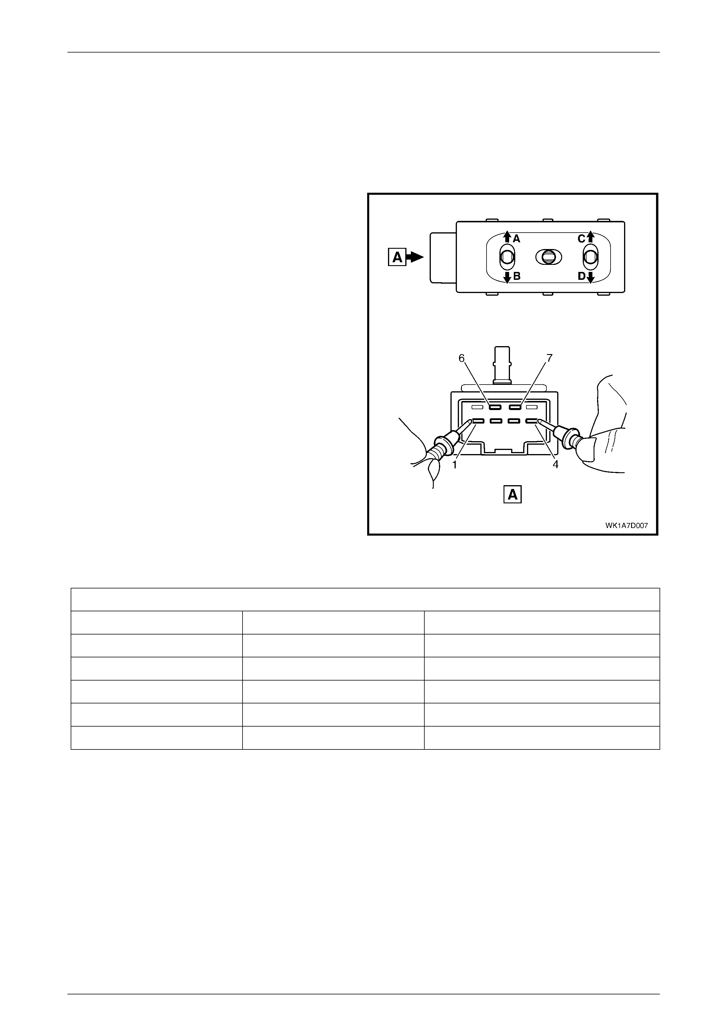
Seat Assemblies Page 1A7–80
Page 1A7–80
3.4 Four-way Seat Adjustment Sw itch Test
The switch is located on the outer side of the seat, attached to the inner side of the front seat outer side cover.
Test
1 Remove the four-way seat adju stment switch, refer to 2.4 Front Seat Outer Side Cover Assembly.
2 Place the switch in the positions as detailed in the
chart in this Section. Place the probes of the
ohmmeter onto the terminals listed and take the
reading. Compare the reading to the chart.
3 If the switch fails any part of the test, replace the
switch assembly with a serviceable item.
4 Install the four-way seat adjustment switch, refer to
2.4 Front Seat Outer Side Cover Assembly.
Figure 1A7 – 69
Four-way Seat Adjustment Switch
Switch Posi tion Switch Terminals Indication if Switch is Serviceable
Position A 3 and 7 Continuity
Position B 2 and 7 Continuity
Position C 4 and 7 Continuity
Position D 1 and 7 Continuity
Switch in the neutral position 6 and either 1, 2, 3 or 4 Continuity
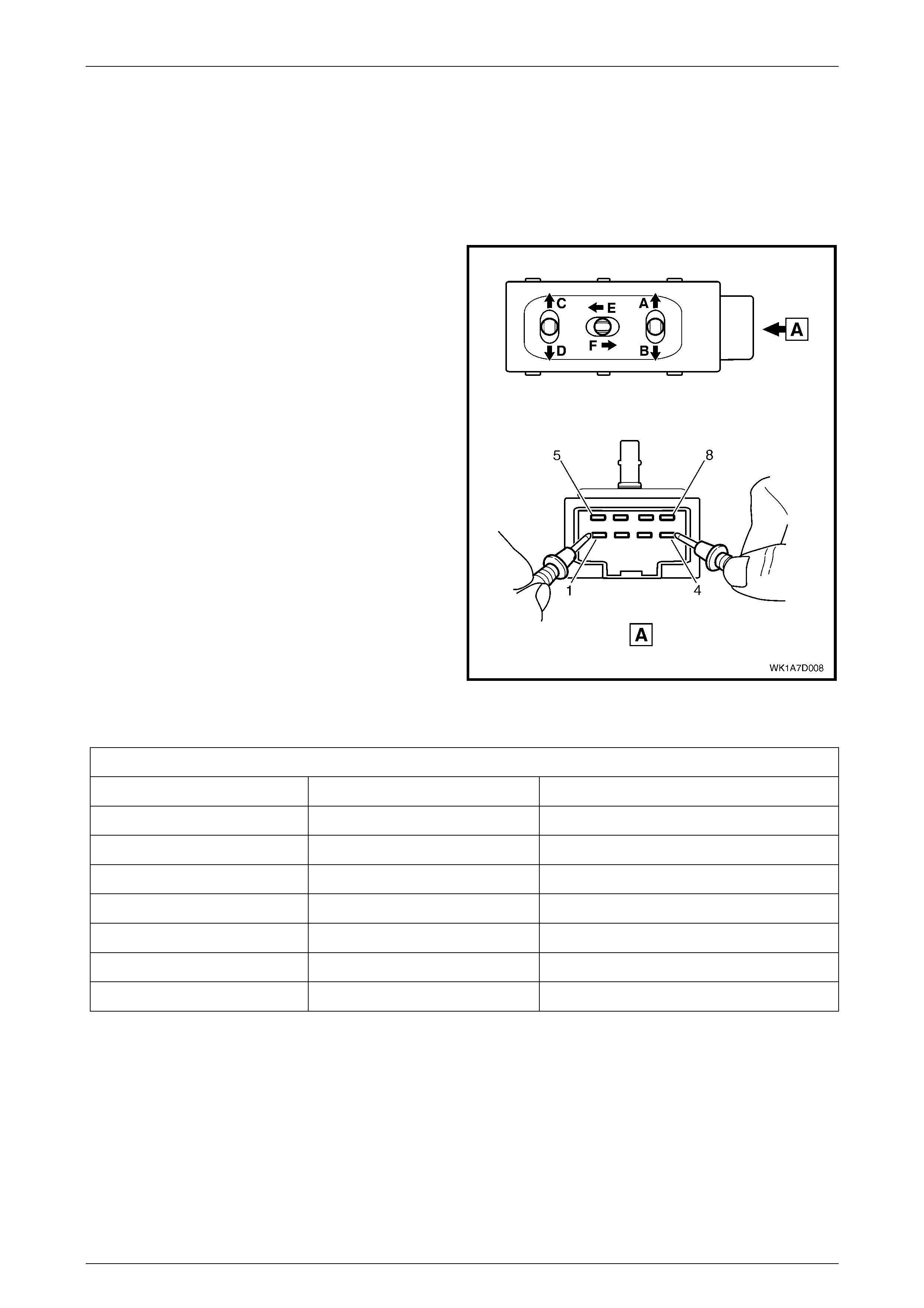
Seat Assemblies Page 1A7–81
Page 1A7–81
3.5 Six-way Seat Adjustment Switch Test
The switch is located on the outer side of the seat, attached to the inner side of the front seat outer side cover.
Test
1 Remove the six-way seat adjustment switch, refer to 2.4 Front Seat Outer Side Cover Assembly.
2 Place the switch in the positions as detailed in the
chart in this Section. Place the probes of the
ohmmeter onto the terminals listed and take the
reading. Compare the reading to the chart.
3 If the switch fails any part of the test, replace the
switch assembly with a serviceable item.
4 Install the six-way seat adjustment switch, refer to
2.4 Front Seat Outer Side Cover Assembly.
Figure 1A7 – 70
Six-way Seat Adjustment Switch
Switch Posi tion Switch Terminals Indication if Switch is Serviceable
Position A 2 and 7 Continuity
Position B 3 and 7 Continuity
Position C 1 and 7 Continuity
Position D 4 and 7 Continuity
Position E 8 and 7 Continuity
Position F 5 and 7 Continuity
Switch in the neutral position 6 and either 1, 2, 3, 4, 5 or 8 Continuity

Seat Assemblies Page 1A7–82
Page 1A7–82
3.6 Electrical Diagnosis – Eight-way Seat
The charts in this Section are used by the technician in the aid of diagnosing faults on eight-way seat assemblies. To aid
in the use of the diagnosis charts, refer to Wiring Diagram – Eight-way Seat, Non-memory and Connector Chart – Eight-
way Seat in this Section.

Seat Assemblies Page 1A7–83
Page 1A7–83
Wiring Diagram – Eight-way Seat
Figure 1A7 – 71
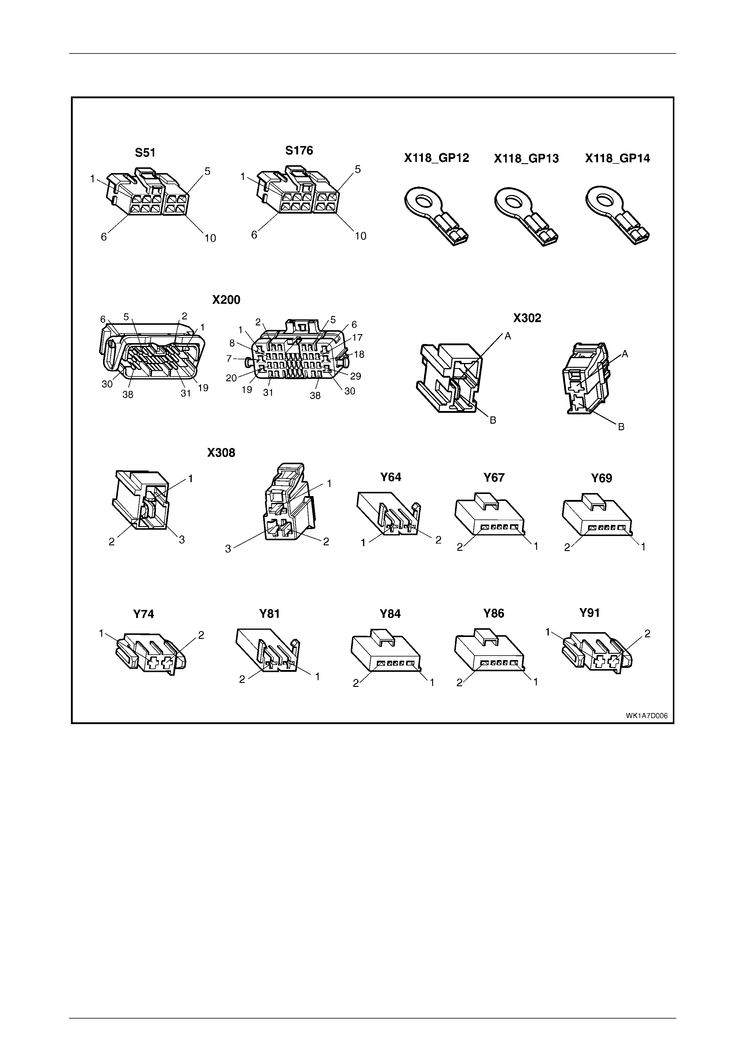
Seat Assemblies Page 1A7–84
Page 1A7–84
Connector Chart – Eight-way Seat
Figure 1A7 – 72

Seat Assemblies Page 1A7–85
Page 1A7–85
Neither Seat Adjustment Switch Functions Operate
Introduction
This test is used by the technician to aid in the diagnosis of the seat power and ground circuits, if neither seat operates
when either seat adjustment switch is operated.
Test Description
The following numbers refer to the Step numbers in the diagnostic chart.
1 Checks that battery voltage is more than 11.5 volts. The seat motors require more than 11.5 volts to operate
correctly.
2 Checks that circuit breaker F2 located on the passenger compartment fuse and relay panel assembly is not tripped.
Isolates whether circuit breaker F2 is the fault affecting the circuit between the battery and connector X200 pin 19.
3 Checks that fusible link F105 located on the engine compartment fuse and relay panel assembly is serviceable.
Isolates whether the fusible link is the fault affecting the circuit between the battery and connector X200 pin 19.
4 Ensures that connector X200 is secure.
5 Checks whether there is battery voltage at connector X200 pin 19. Isolates whether the fault is between the battery
and connector X200 pin 19. If the fault in the circuit is between connectors X200 pin 19 and either X308 pin 3 or
X302 pin B, only one seat will not operate.
6 Checks whether there is battery voltage at circuit breaker F2. Isolates whether the fault is between the battery and
circuit breaker F2 or circuit breaker F2 and connector X200 pin 19.
7 Checks whether there is battery voltage at fusible link F105. Isolates whether the fault is between the battery and
fusible link F105 or fusible link F105 and circuit breaker F2.
8 Checks that all the ground points associated with the system are serviceable and a good ground is provided at
each point.
Step Action Yes No
1 1 Check the battery voltage, refer to Section
12A, 2.9 Battery.
Is the battery voltage more than 11.5 V? Go to Step 2. Refer to Section 12A,
2.9 Battery for further
diagnosis.
2 1 Inspect circuit breaker F2, refer to Section
12O, 2.2 Circuit Breakers.
Is circuit breaker F2 tripped?
Allow the circuit breaker to
reset, refer to Section 12O,
2.2 Circuit Breakers. Go to Step 3.
3 1 Inspect fusible link F105, refer to Section
12O, 2.3 Fusible Links.
Is fuse F105 serviceable? Go to Step 4. Replace the fusible link.
4 Is connector X200 secure? Go to Step 5. Ensure that the connector is
secure.
5 1 Back probe connector X200 pin 19 with a
test lamp.
Does the test lamp illuminate? Go to Step 8. Go to Step 6.
6 1 Remove circuit breaker F2 from the
passenger comp artm ent fus e and relay
panel assembly.
2 Using a test lamp, probe connector
X129 – X4 5 pin – 2. Refer to Section 12P
Wiring Diagrams.
Does the test lamp illuminate?
There is a fault in circuit 540
between circ uit breaker F2 and
connector X200 pin 19.
Repair or replace circuit 540.
Go to Step 7.

Seat Assemblies Page 1A7–86
Page 1A7–86
Step Action Yes No
7 1 Remove fusible link F105.
2 Using a test lamp, probe connector
X18-105. Refer to Section 12P Wiring
Diagrams.
Does the test lamp illuminate?
There is a fault in circuit 342
between fusible link F105 and
circuit breaker F2.
Repair or replace circuit 342.
There is a fa ult in circ uit 1
between the battery and
fusible link F105.
Repair or replace circuit 1.
8 1 Ensure that the following ground points are
secure and have good contact with the
vehicle structure:
• X118–GP12 located in the middle of
the transmission tunnel.
• X118–GP13 located in the rear
compartment on the right-hand side
tail lamp stud.
• X118–GP14 located on the rear
compartment lid .
Refer to Section 12P Wiring Diagrams for further
details of ground ing poi nts.
Are all the ground points secure to the vehicle
with a good contact?
There is a fault in circuit 650.
Repair or replace circuit 650.
Ensure that the connectors are
secured to the vehicle and that
there is a good contact
between the conne ctor and th e
vehicle.
When all diagnosis and repairs are completed, check the system for correct operation.

Seat Assemblies Page 1A7–87
Page 1A7–87
None of the Driver’s Seat Adjustment Switch Functi ons Operate
Introduction
This test is used by the technician to aid in the diagnosis of the driver’s seat adjustment switch when none of the switch
functions operate. The test diagnoses the driver’s seat adjustment switch and associated power and ground circuits.
Test Description
The following numbers refer to the Step numbers in the diagnostic chart.
1 Checks whether all of the passenger seat functions wo rk. If none of them work, the fault is not isolated to the
driver’s seat only .
2 Checks whether there is battery power at connector X308 pin 3. Isolates whether there is a fault in circuit 540
between connectors X200 pin 19 and X308 pin 3.
3 Checks that all the connectors required for the seat to operate effectively are in place and positively connected.
4 Checks whether there is battery power at connector S51 – X1 pin 5. Isolates whether there is a fault in ci rcuit 540
between connectors S51 – X1 pin 5 and X308 pin 3.
5 Checks whether the driver’s seat adjustment switch is serviceable.
6 Checks whether there is continuity between connectors S51 – X1 pin 1 and X308 pin 1 which supplies the ground
circuit for the driver’s seat adjustment switch. Isolates whether there is a fault in circuit 650 between the switch and
connector X308 pin 1 or between connector X308 pin 1 and the grounding points.
Step Action Yes No
1
A
re all of the passenger’s seat adjustment switch
functions inoperative? Refer to Neither Seat
Adjustment Switc h Functions
Operate in this Section. Go to Step 2.
2 1 Back probe connector X308 pin 3 with a
test lamp.
Does the test lamp illuminate? Go to Step 3.
There is a fault in circuit 540
between connectors
X200 pin 19 and X308 pin 3.
Repair or repl ace circuit 540.
3 Are the following connectors secure?
• S51
• X308
• Y64
• Y67
• Y69
• Y74
Go to Step 4. Ensure that the connectors are
secure.
4 1 Back probe connector S51 – X1 pin 5 with
a test lamp.
Does the test lamp illuminate? Go to Step 5.
There is a fault in circuit 540
between connectors
S51 – X1 pin 5 and X308 pin 3.
Repair or repl ace circuit 540.
5 1 Remove the driver’s seat adjustment
switch from the seat, re fer to 2.4 Front
Seat Outer Side Cover Assembly.
2 Test the driver’s seat adjustment switch,
refer to 3.7 Eight-way Seat Adjustment
Switch Test.
Is the driver’s seat adjustment switch
serviceable?
Go to Step 6.
Replace the driver’s seat
adjustment switch.
Refer to 2.4 Front Seat Outer
Side Cover Assembly.

Seat Assemblies Page 1A7–88
Page 1A7–88
Step Action Yes No
6 1 Back probe connector X308 pin 1 with a
test lamp.
2 Operate the driver’s seat adjustment switch
in any of the available directions.
Does the test lamp illuminate?
There is a fault in circuit 650
between connector X308 pin 1
and ground points X118–
GP12, X118–GP13 and X118–
GP14.
Repair or replace circuit 650.
There is a fault in circuit 650
between connectors
S51 – X1 pin 1 and X308 pin 1.
Repair or repl ace circuit 650.
When all diagnosis and repairs are completed, check the system for correct operation.

Seat Assemblies Page 1A7–89
Page 1A7–89
Front/Rear of the Driver’s Seat Does Not Raise and/or Lower
Introduction
This test is used by the technician to aid in the diagnosis of the front and/or the rear of the driver’s seat not raising and/or
lowering. The test diagnoses the seat adjustment switch and the motor circuits.
Test Description
The following numbers refer to the Step numbers in the diagnostic chart.
1 Checks whether the driver’s seat adjustment switch operates the seat in any direction. Isolates whether the power
and ground circuits are at fault.
2 Checks that all the connectors required for the seat to operate effectively are in place and positively connected.
3 Checks whether the driver’s seat adjustment switch is serviceable.
4 Confirms whether the rear of the seat raises or lowers. Isolates whether the rear lift motor and circuit of the seat is
the fault.
5 Confirms whether the front of the seat raises or lowers. Isolates whether the front lift motor and circuit of the seat is
the fault.
6 Checks whether there is battery power to the seat rear lift motor at connector Y69 – X1 pin 1. Isolates whether
there is a fault in circuit 282 that supplies battery power to the motor to raise the rear of the seat.
7 Checks whether there is battery power to the seat rear lift motor at connector Y69 – X1 pin 2. Isolates whether the
fault is in circuit 283 that supplies battery power to the motor to lower the rear of the seat or the motor is faulty. As
the direction of the motor is changed by reversing the polarity, this Step also confirms that the ground circuit from
Step 6 is serviceable.
8 Checks whether there is battery power to the seat front lift motor at connector Y67 – X1 pin 1. Isolates whether
there is a fault in circuit 286 that supplies battery power to the motor to raise the front of the seat.
9 Checks whether there is battery power to the seat front lift motor at connector Y67 – X1 pin 2. Isolates whether the
fault is in circuit 287 that supplies battery power to the motor to lower the front of the seat or the motor is faulty. As
the direction of the motor is changed by reversing the polarity, this Step also confirms that the ground circuit from
Step 8 is serviceable.
Step Action Yes No
1 Does the driver’s seat adjustment switch operate
the seat correctly in any of the eight directions? Go to Step 2.
Refer to None of the Driver’s
Seat Adjustment Switch
Functions Operate in this
Section.
2 Are the following connectors secure?
• S51
• Y67
• Y69
Go to Step 3. Ensure that the connectors are
secure.
3 1 Remove the driver’s seat adjustment
switch from the seat, re fer to 2.4 Front
Seat Outer Side Cover Assembly.
2 Test the driver’s seat adjustment switch,
refer to 3.7 Eight-way Seat Adjustment
Switch Test.
Is the driver’s seat adjustment switch
serviceable?
Go to Step 4.
Replace the driver’s seat
adjustment switch.
Refer to 2.4 Front Seat Outer
Side Cover Assembly.
4 1 Operate the driver’s seat adjustment switch
to raise or lower the rear of the seat.
Does the rear of the seat raise and lower? Go to Step 5. Go to Step 6.

Seat Assemblies Page 1A7–90
Page 1A7–90
Step Action Yes No
5 1 Operate the driver’s seat adjustment switch
to raise or lower the front of the seat.
Does the fron t of the seat raise and lower? System serviceable. Go to Step 8.
6 1 Back probe connector Y69 – X1 pin 1 with
a test lamp.
2 Operate the driver’s seat adjustment switch
to raise the rear of the seat.
Does the test lamp illuminate?
Go to Step 7.
There is a fault in circuit 282
between connectors
S51 – X1 pin 8 and
Y69 – X1 pin 1.
Repair or repl ace circuit 282.
7 1 Back probe connector Y69 – X1 pin 2 with
a test lamp.
2 Operate the driver’s seat adjustment switch
to lower the rear of the seat.
Does the test lamp illuminate?
The seat rear lift motor is
faulty.
Replace the seat rear lift
motor, refer to 2.14 Front Seat
Lift Motor Assemblies.
Go to Step 5.
There is a fault in circuit 283
between connectors
S51 – X1 pin 9 and
Y69 – X1 pin 2.
Repair or repl ace circuit 283.
Go to Step 5.
8 1 Back probe connector Y67 – X1 pin 1 with
a test lamp.
2 Operate the driver’s seat adjustment switch
to raise the front of the seat.
Does the test lamp illuminate?
Go to Step 9.
There is a fault in circuit 286
between connectors
S51 – X1 pin 7 and
Y67 – X1 pin 1.
Repair or repl ace circuit 286.
9 1 Back probe connector Y67 – X1 pin 2 with
a test lamp.
2 Operate the driver’s seat adjustment switch
to lower the front of the seat.
Does the test lamp illuminate?
The seat front lift motor is
faulty.
Replace the seat front lift
motor, refer to 2.14 Front Seat
Lift Motor Assemblies.
There is a fault in circuit 287
between connectors
S51 – X1 pin 10 and
Y67 – X1 pin 2.
Repair or repl ace circuit 287.
When all diagnosis and repairs are completed, check the system for correct operation.

Seat Assemblies Page 1A7–91
Page 1A7–91
Driver’s Seat Fore/Af t Movement Function is Inoperative or Not Smooth
Introduction
This test is used by the technician to aid in the diagnosis of the fore/aft movement function of the driver’s seat being
inoperative or the action of the seat through the range of movement is not sm ooth. The test diagnoses the seat
adjustment switch and the motor circuits.
Test Description
The following numbers refer to the Step numbers in the diagnostic chart.
1 Checks whether the driver’s seat adjustment switch operates the seat in any direction. Isolates whether there is
battery power to the switch assembly.
2 Checks that there are no items obstructing the guide rails, which may stop or hinder the seat movement.
3 Checks that the guide rails and drive shafts have adequate lubricant applied to provide a smooth operation of the
seat.
4 Checks that the guide rails or drive shafts have not been damaged. Any binding between the mo ving parts will
result in poor operation of the fore and aft movement.
5 Checks that all the connectors required for the seat to operate effectively are in place and positively connected.
6 Checks whether the driver’s seat adjustment switch is serviceable.
7 Checks whether there is battery power to the seat fore/aft movement motor at connector Y64 – X1 pin 1. Isolates
whether there is a fault in circuit 285 that supplies battery power to the motor to move the seat forward.
8 Checks whether there is battery power to the seat fore/aft movement motor at connector Y64 – X1 pin 2. Isolates
whether the fault is in circuit 284 that supplies battery power to the motor to move the seat aft or the motor is faulty.
As reversing the polarity changes the direction of the motor, this Step also confirms that the ground circuit from
Step 7 is serviceable.
Step Action Yes No
1 Does the driver’s seat adjustment switch operate
the seat correctly in any of the eight directions? Go to Step 2.
Refer to None of the Driver’s
Seat Adjustment Switch
Functions Operate in this
Section.
2 Are the guide rails free from obstructions? Go to Step 3. Remove the obstructing item.
3 Are the guide rails and drive shafts adequately
lubricated? Go to Step 4.
Apply a small amount of
grease type NLGI No. 1
Lithium Grease (with 9% Zinc
Oxide).
4 Do the guide rails or drive shafts bind at any
point of travel during the fore and aft movement
of the seat?
Replace the track and height
adjust assembly.
Refer to 2.11 Track and Height
Adjust Assembly.
Go to Step 5.
5 Are the following connectors secure?
• S51
• Y64
Go to Step 6. Ensure that the connectors are
secure.
6 1 Remove the driver’s seat adjustment
switch from the seat, re fer to 2.4 Front
Seat Outer Side Cover Assembly.
2 Test the driver’s seat adjustment switch,
refer to 3.7 Eight-way Seat Adjustment
Switch Test.
Is the driver’s seat adjustment switch
serviceable?
Go to Step 7.
Replace the driver’s seat
adjustment switch.
Refer to 2.4 Front Seat Outer
Side Cover Assembly.

Seat Assemblies Page 1A7–92
Page 1A7–92
Step Action Yes No
7 1 Back probe connector Y64 – X1 pin 1 with
a test lamp.
2 Operate the driver’s seat adjustment switch
to move the seat forward.
Does the test lamp illuminate?
Go to Step 8.
There is a fault in circuit 285
between connectors
S51 – X1 pin 6 and
Y64 – X1 pin 1.
Repair or repl ace circuit 285.
8 1 Back probe connector Y64 – X1 pin 2 with
a test lamp.
2 Operate the driver’s seat adjustment switch
to move the seat aft.
Does the test lamp illuminate?
The seat fore/aft movement
motor is faulty.
Replace the seat fore/aft
movement motor, refer to
2.15 Front Seat Fore/Aft
Movement Mot or Assem bly.
There is a fault in circuit 284
between connectors
S51 – X1 pin 3 and
Y64 – X1 pin 2.
Repair or repl ace circuit 284.
When all diagnosis and repairs are completed, check the system for correct operation.

Seat Assemblies Page 1A7–93
Page 1A7–93
Driver’s Seat-back Recline Forward and/or Aft Function is Inoperative
Introduction
This test is used by the technician to aid in the diagnosis of the recline function of the driver’s seat being inoperative. The
test diagnoses the seat adjus t ment switch and the motor circ uits.
Test Description
The following numbers refer to the Step numbers in the diagnostic chart.
1 Checks whether the driver’s seat adjustment switch operates the seat in any direction. Isolates whether there is
battery power to the switch assembly.
2 Checks that all the connectors required for the seat to operate effectively are in place and positively connected.
3 Checks whether the driver’s seat adjustment switch is serviceable.
4 Checks whether there is battery power to the seat-back recline motor at connector Y74 – X1 pin 1. Isolates whether
there is a fault in circuit 276 that supplies battery power to the motor to move the seat-back forward.
5 Checks whether there is battery power to the seat-back recline motor at connector Y74 – X1 pin 2. Isolates whether
the fault is in circuit 277 that supplies battery power to the motor to move the seat-back aft or the motor is faulty. As
reversing the polarity changes the direction of the motor, this Step also confirms that the ground circuit from Step 4
is serviceable.
Step Action Yes No
1 Does the driver’s seat adjustment switch operate
the seat correctly in any of the eight directions? Go to Step 2.
Refer to None of the Driver’s
Seat Adjustment Switch
Functions Operate in this
Section.
2 Are the following connectors secure?
• S51
• Y74
Go to Step 3. Ensure that the connectors are
secure.
3 1 Remove the driver’s seat adjustment
switch from the seat, re fer to 2.4 Front
Seat Outer Side Cover Assembly.
2 Test the driver’s seat adjustment switch,
refer to 3.7 Eight-way Seat Adjustment
Switch Test.
Is the driver’s seat adjustment switch
serviceable?
Go to Step 4.
Replace the driver’s seat
adjustment switch.
Refer to 2.4 Front Seat Outer
Side Cover Assembly.
4 1 Back probe connector Y74 – X1 pin 1 with
a test lamp.
2 Operate the driver’s seat adjustment switch
to move the seat-back f orw ard.
Does the test lamp illuminate?
Go to Step 5.
There is a fault in circuit 276
between connectors
S51 – X1 pin 2 and
Y74 – X1 pin 1.
Repair or repl ace circuit 276.
5 1 Back probe connector Y74 – X1 pin 2 with
a test lamp.
2 Operate the driver’s seat adjustment switch
to move the seat-ba ck aft.
Does the test lamp illuminate?
The seat-back recline motor is
faulty.
Replace the seat-back recline
motor, refer to 2.16 Front Seat-
back Recline Motor Assembly.
There is a fault in circuit 277
between connectors
S51 – X1 pin 4 and
Y74 - X1 pin 2.
Repair or repl ace circuit 277.
When all diagnosis and repairs are completed, check the system for correct operation.

Seat Assemblies Page 1A7–94
Page 1A7–94
None of the Passenger’s Seat Adjustment Switch Functions Operate
Introduction
This test is used by the technician to aid in the diagnosis of the passenger’s seat adjustment switch when none of the
switch functions operate. The test diagnoses the passenger’s seat adjustment switch and associated power and ground
circuits.
Test Description
The following numbers refer to the Step numbers in the diagnostic chart.
1 Checks whether all of the driver’s seat functions work. If none of them work, the fault is not isolated to the
passenger’s seat only.
2 Checks whether there is battery power at connector X302 pin B. Isolates whether there is a fault in circuit 540
between connectors X200 pin 19 and X302 pin B.
3 Checks that all the connectors required for the seat to operate effectively are in place and positively connected.
4 Checks whether there is battery power at connector S176 – X1 pin 5. Isolates whether there is a fault in circuit 540
between connectors S176 – X1 pin 5 and X302 pin B.
5 Checks whether the passen ge r’s seat adjustment switch is serv iceab le.
6 Checks whether there is continuity between connectors S176 – X1 pin 1 and X302 pin A which supplies the ground
circuit for the passenger’s seat adjustment switch. Isolates whether there is a fault in circuit 650 between the switch
and connector X302 pin A or between connector X302 pin A and the grounding points.
Step Action Yes No
1 Are all of the driver’s seat adjustment switch
functions inoperative? Refer to Neither Seat
Adjustment Switc h Functions
Operate in this Section. Go to Step 2.
2 1 Back probe connector X302 pin B with a
test lamp.
Does the test lamp illuminate? Go to Step 3.
There is a fault in circuit 540
between connectors X200 pin
19 and X302 pin B.
Repair or repl ace circuit 540.
3 Are the following connectors secure?
• S176
• X302
• Y81
• Y84
• Y86
• Y91
Go to Step 4. Ensure that the connectors are
secure.
4 1 Back probe connector S176 – X1 pin 5 with
a test lamp.
Does the test lamp illuminate? Go to Step 5.
There is a fault in circuit 540
between connectors
S176 – X1 pin 5 and
X302 pin B.
Repair or repl ace circuit 540.
5 1 Remove the passenger’s seat adjustment
switch from the seat, refer to 2.4 Front
Seat Outer Side Cover Assembly.
2 Test the passenger’s seat adjustment
switch, refer to 3.7 Eight-way Seat
Adjustment Switch Test.
Is the passenger’s seat adjustment switch
serviceable?
Go to Step 6.
Replace the passenger’s seat
adjustment switch.
Refer to 2.4 Front Seat Outer
Side Cover Assembly.

Seat Assemblies Page 1A7–95
Page 1A7–95
Step Action Yes No
6 1 Back probe connector X302 pin A with a
test lamp.
2 Operate the passenger’s seat adjustment
switch in any of the available directions.
Does the test lamp illuminate?
There is a fault in circuit 650
between connector X302 pin A
and ground points X118–
GP12, X118–GP13 and X118–
GP14.
Repair or replace circuit 650.
There is a fault in circuit 650
between connectors
S176 – X1 pin 1 and
X302 pin A.
Repair or repl ace circuit 650.
When all diagnosis and repairs are completed, check the system for correct operation.

Seat Assemblies Page 1A7–96
Page 1A7–96
Front/Rear of the Passenger’s Seat Does Not Raise and/or Lower
Introduction
This test is used by the technician to aid in the diagnosis of the front and/or the rear of the passenger’s seat not raising
and/or lowering. The test diagnoses the seat adjustment switch and the motor circuits.
Test Description
The following numbers refer to the Step numbers in the diagnostic chart.
1 Checks whether the passen ge r’s seat adj ustment switch operates the sea t in any direct ion. Isolates whether the
power and ground circui ts are at fault.
2 Checks that all the connectors required for the seat to operate effectively are in place and positively connected.
3 Checks whether the passen ge r’s seat adjustment switch is serv iceab le.
4 Confirms whether the rear of the seat raises or lowers. Isolates whether the rear lift motor and circuit of the seat is
the fault.
5 Confirms whether the front of the seat raises or lowers. Isolates whether the front lift motor and circuit of the seat is
the fault.
6 Checks whether there is battery power to the seat rear lift motor at connector Y86 – X1 pin 1. Isolates whether
there is a fault in circuit 288 that supplies battery power to the motor to raise the rear of the seat.
7 Checks whether there is battery power to the seat rear lift motor at connector Y86 – X1 pin 2. Isolates whether the
fault is in circuit 289 that supplies battery power to the motor to lower the rear of the seat or the motor is faulty. As
the direction of the motor is changed by reversing the polarity, this Step also confirms that the ground circuit from
Step 6 is serviceable.
8 Checks whether there is battery power to the seat front lift motor at connector Y84 – X1 pin 1. Isolates whether
there is a fault in circuit 297 that supplies battery power to the motor to raise the front of the seat.
9 Checks whether there is battery power to the seat front lift motor at connector Y84 – X1 pin 2. Isolates whether the
fault is in circuit 298 that supplies battery power to th e motor to lower the front of the seat or the motor is faulty. As
the direction of the motor is changed by reversing the polarity, this Step also confirms that the ground circuit from
Step 8 is serviceable.
Step Action Yes No
1 Does the passenger’s seat adjustment switch
operate the seat correctly in any of the eight
directions? Go to Step 2.
Refer to None of the
Passenger’s Seat Adjustment
Switch Functions Operate in
this Section.
2 Are the following connectors secure?
• S176
• Y84
• Y86
Go to Step 3. Ensure that the connectors are
secure.
3 1 Remove the passenger’s seat adjustment
switch from the seat, re fer to 2.4 Front
Seat Outer Side Cover Assembly.
2 Test the passenger’s seat adjustment
switch, refer to 3.7 Eight-way Seat
Adjustment Switch Test.
Is the passenger’s seat adjustment switch
serviceable?
Go to Step 4.
Replace the passenger’s seat
adjustment switch.
Refer to 2.4 Front Seat Outer
Side Cover Assembly.
4 1 Operate the passenger’s seat adjustment
switch to raise or lower the rear of the seat.
Does the rear of the seat raise and lower? Go to Step 5. Go to Step 6.

Seat Assemblies Page 1A7–97
Page 1A7–97
Step Action Yes No
5 1 Operate the passenger’s seat adjustment
switch to raise or lower the front of the
seat.
Does the fron t of the seat raise and lower?
System serviceable. Go to Step 8.
6 1 Back probe connector Y86 – X1 pin 1 with
a test lamp.
2 Operate the passenger’s seat adjustment
switch to raise the rear of the seat.
Does the test lamp illuminate?
Go to Step 7.
There is a fault in circuit 288
between connectors
S176 – X1 pin 9 and
Y86 – X1 pin 1.
Repair or repl ace circuit 288.
7 1 Back probe connector Y86 – X1 pin 2 with
a test lamp.
2 Operate the passenger’s seat adjustment
switch to lower the rear of the seat.
Does the test lamp illuminate?
The seat rear lift motor is
faulty.
Replace the seat rear lift
motor, refer to 2.14 Front Seat
Lift Motor Assemblies.
Go to Step 5.
There is a fault in circuit 289
between connectors
S176 – X1 pin 8 and
Y86 – X1 pin 2.
Repair or repl ace circuit 289.
Go to Step 5.
8 1 Back probe connector Y84 – X1 pin 1 with
a test lamp.
2 Operate the passenger’s seat adjustment
switch to raise the front of the seat.
Does the test lamp illuminate?
Go to Step 9.
There is a fault in circuit 297
between connectors
S176 – X1 pin 10 and
Y84 – X1 pin 1.
Repair or replace circuit 297.
9 1 Back probe connector Y84 – X1 pin 2 with
a test lamp.
2 Operate the passenger’s seat adjustment
switch to lower the front of the seat.
Does the test lamp illuminate?
The seat front lift motor is
faulty.
Replace the seat front lift
motor, refer to 2.14 Front Seat
Lift Motor Assemblies.
There is a fault in circuit 298
between connectors
S176 – X1 pin 7 and
Y84 – X1 pin 2.
Repair or repl ace circuit 298.
When all diagnosis and repairs are completed, check the system for correct operation.

Seat Assemblies Page 1A7–98
Page 1A7–98
Passenger’s Seat Fore/Aft Movement Function is Inoperative or Not Smooth
Introduction
This test is used by the technician to aid in the diagnosis of the fore/aft movement function of the passenger’s seat being
inoperative or the action of the seat through the range of movement is not sm ooth. The test diagnoses the seat
adjustment switch and the motor circuits.
Test Description
The following numbers refer to the Step numbers in the diagnostic chart.
1 Checks whether the passen ge r’s seat adj ustment switch operates the sea t in any direct ion. Isolates whether there
is battery power to the switch assembly.
2 Checks that there are no items obstructing the guide rails, which may stop or hinder the seat movement.
3 Checks that the guide rails and drive shafts have adequate lubricant applied to provide a smooth operation of the
seat.
4 Checks that the guide rails or drive shafts have not been damaged. Any binding between the moving parts will
result in poor operation of the fore and aft movement.
5 Checks that all the connectors required for the seat to operate effectively are in place and positively connected.
6 Checks whether the passen ge r’s seat adjustment switch is serv iceab le.
7 Checks whether there is battery power to the seat fore/aft movement motor at connector Y81 – X1 pin 1. Isolates
whether there is a fault in circuit 296 that supplies battery power to the motor to move the seat forward.
8 Checks whether there is battery power to the seat fore/aft movement motor at connector Y81 – X1 pin 2. Isolates
whether the fault is in circuit 290 that supplies battery power to the motor to move the seat aft or the motor is faulty.
As reversing the polarity changes the direction of the motor, this Step also confirms that the ground circuit from
Step 7 is serviceable.
Step Action Yes No
1 Does the passenger’s seat adjustment switch
operate correctly in any of the eight directions? Go to Step 2.
Refer to None of the
Passenger’s Seat Adjustment
Switch Functions Operate in
this Section.
2 Are the guide rails free from obstructions? Go to Step 3. Remove the obstructing item.
3 Are the guide rails and drive shafts adequately
lubricated? Go to Step 4.
Apply a small amount of
grease type NLGI No. 1
Lithium Grease (with 9% Zinc
Oxide).
4 Do the guide rails or drive shafts bind at any
point of travel during the fore and aft movement
of the seat?
Replace the track and height
adjust assembly.
Refer to 2.11 Track and Height
Adjust Assembly.
Go to Step 5.
5 Are the following connectors secure?
• S176
• Y81
Go to Step 6. Ensure that the connectors are
secure.
6 1 Remove the passenger’s seat adjustment
switch from the seat, re fer to 2.4
Front Seat Outer Side Cover Assembly.
2 Test the passenger’s seat adjustment
switch, refer to 3.7 Eight-way Seat
Adjustment Switch Test.
Is the passenger’s seat adjustment switch
serviceable?
Go to Step 7.
Replace the passenger’s seat
adjustment switch.
Refer to 2.4 Front Seat Outer
Side Cover Assembly.

Seat Assemblies Page 1A7–99
Page 1A7–99
Step Action Yes No
7 1 Back probe connector Y81 – X1 pin 1 with
a test lamp.
2 Operate the passenger’s seat adjustment
switch to move the seat forw ard.
Does the test lamp illuminate?
Go to Step 8.
There is a fault in circuit 296
between connectors
S176 – X1 pin 6 and
Y81 – X1 pin 1.
Repair or repl ace circuit 296.
8 1 Back probe connector Y81 – X1 pin 2 with
a test lamp.
2 Operate the passenger’s seat adjustment
switch to move the seat aft.
Does the test lamp illuminate?
The seat fore/aft movement
motor is faulty.
Replace the seat fore/aft
movement motor, refer to
2.15 Front Seat Fore/Aft
Movement Mot or Assem bly.
There is a fault in circuit 290
between connectors
S176 – X1 pin 3 and
Y81 – X1 pin 2.
Repair or repl ace circuit 290.
When all diagnosis and repairs are completed, check the system for correct operation.

Seat Assemblies Page 1A7–100
Page 1A7–100
Passenger’s Seat-back Recline Forward and/or Aft Funct i on is Inoperative
Introduction
This test is used by the technician to aid in the diagnosis of the recline function of the passenger’s seat being inoperative.
The test diagnoses the seat adjustment switch and the motor circuits.
Test Description
The following numbers refer to the Step numbers in the diagnostic chart.
1 Checks whether the passen ge r’s seat adj ustment switch operates the sea t in any direct ion. Isolates whether there
is battery power to the switch assembly.
2 Checks that all the connectors required for the seat to operate effectively are in place and positively connected.
3 Checks whether the passen ge r’s seat adjustment switch is serv iceab le.
4 Checks whether there is battery power to the seat-back recline motor at connector Y91 – X1 pin 1. Isolates whether
there is a fault in circuit 76 that supplies battery power to the motor to move the seat-back forward.
5 Checks whether there is battery power to the seat-back recline motor at connector Y91 – X1 pin 2. Isolates whether
the fault is in circuit 77 that supplies battery power to the motor to move the seat-back aft or the motor is faulty. As
reversing the polarity changes the direction of the motor, this Step also confirms that the ground circuit from Step 4
is serviceable.
Step Action Yes No
1 Does the passenger’s seat adjustment switch
operate the seat correctly in any of the eight
directions? Go to Step 2.
Refer to None of the
Passenger’s Seat Adjustment
Switch Functions Operate in
this Section.
2 Are the following connectors secure?
• S176
• Y91
Go to Step 3. Ensure that the connectors are
secure.
3 1 Remove the passenger’s seat adjustment
switch from the seat, re fer to 2.4 Front
Seat Outer Side Cover Assembly.
2 Test the passenger’s seat adjustment
switch, refer to 3.7 Eight-way Seat
Adjustment Switch Test.
Is the passenger’s seat adjustment switch
serviceable?
Go to Step 4.
Replace the passenger’s seat
adjustment switch.
Refer to 2.4 Front Seat Outer
Side Cover Assembly.
4 1 Back probe connector Y91 – X1 pin 1 with
a test lamp.
2 Operate the passenger’s seat adjustment
switch to move the seat-back forward.
Does the test lamp illuminate?
Go to Step 5.
There is a fault in circuit 76
between connectors
S176 – X1 pin 2 and
Y91 – X1 pin 1.
Repair or replace circuit 76.
5 1 Back probe connector Y91 – X1 pin 2 with
a test lamp.
2 Operate the passenger’s seat adjustment
switch to move the seat- bac k aft.
Does the test lamp illuminate?
The seat-back recline motor is
faulty.
Replace the seat-back recline
motor, refer to 2.16 Front Seat-
back Recline Motor Assembly.
There is a fault in circuit 77
between connectors
S176 – X1 pin 4 and
Y91 – X1 pin 2.
Repair or replace circuit 77.
When all diagnosis and repairs are completed, check the system for correct operation.

Seat Assemblies Page 1A7–101
Page 1A7–101
3.7 Eight-way Seat Adjustment Switch Test
The switch is located on the outer side of the seat, attached to the inner side of the front seat outer side cover.
Test
1 Remove the eight-way seat adjustment switch, refer to 2.4 Front Seat Outer Side Cover Assembly.
2 Place the switch in the positions as detailed in the chart in this Section. Place the probes of the ohmmeter onto the
terminals listed and take the reading. Compare the reading to the chart.
3 If the switch fails any part of the test, replace the switch assembly with a serviceable item.
4 Install the eight-way seat adjustment switch, refer to 2.4 Front Seat Outer Side Cover Assembly.
Figure 1A7 – 73
Legend
Left-hand Switch
Right-hand Switc h
Eight-way Seat Adjustment Switch
Switch Posi tion Switch Terminals Indication if Switch is Serviceable
Position A 10 and 5 Continuity
Position B 7 and 5 Continuity
Position C 9 and 5 Continuity
Position D 8 and 5 Continuity
Position E 6 and 5 Continuity
Position F 3 and 5 Continuity
Position G 2 and 5 Continuity
Position H 4 and 5 Continuity
Switch in the neutral position 1 and either 2, 3, 4, 6, 7, 8, 9 or 10 Continuity
Seat Assemblies Page 1A7–102
Page 1A7–102
4 Service Operations – Front Seat,
Level 2, 4 and 5
4.1 Front Seat Usage Chart
NOTE
Running changes to the front seat assemblies
fitted to Level 1 and 3 vehicles occurred during
production. Front seat assemblies fitted to the
M 2004 W K Series after this change are referred
to as "late".
How To Use This Chart
For Level 2, 4 and 5 and late type Level 1 and 3, vehicles, 14 front seat configurations are fitted. The following us age
chart is provided to help determine the seat type fitted to the vehicle. This is important prior to repairs being performed as
the failed/damaged part may not be serviceable. For early type Level 1 and 3 vehicles refer to 2 Service Operations –
Front Seat, Leve l 1 and 3.
To determine the seat fitted to the vehicle, obtain the vehicle model, which seat requires attention and the seat cover
fabric. Then establish other features of the seat such as the electric movement functions. Using the chart will lead to the
elimination of all other seat combinations, allowing the identification of the type and the construction of the seat. Finally,
refer to the Figure shown in Front Seat Type for a component breakdown of the front seat assembly.
1 Vehicle – Vehicle model identification. For Model Level definitions refer to Section 0A General Information.
2 Seating – Driver front seat or passenger front seat.
3 Fabric – Cloth or leather seat covers.
4 Movement – Indicates the number of electric movement functions of the seat:
• Eight-way – Seat cushion front and rear raise/lower, seat fore/aft movement and seat-back recline.
5 Memory – Indicates if a seat memory module is fitted.
6 SIAB – If the front seat is fitted with a side impact airbag assembly.
7 Construction – Hook and Loop refers to the seat cover being attached to the seat pad with a Velcro type material
and both being serviced as separate parts.
8 Head Restraint – Indicates whether fixed or active head restraints are fitted.
9 Front Seat Type – Identifies the seat type and provides reference to the following illustrations which show a
breakdown of the serviced component for each front seat assembly.
Domestic
Vehicle Seating Fabric Movement Memory SIAB Construction Head
Restraint Front Seat Type
(refer to)
Driver Leather or
Cloth Eight-way No Yes Hook & Loop Active 9
(Figure 1A7 – 76)
Statesman
– Level 4
Passenger Leather or
Cloth Eight -way No Yes Hook & Loop Active 10
(Figure 1A7 – 77)
Driver Leather Eight-way Yes Yes Hook & Loop Active 11
(Figure 1A7 – 78)
Caprice
– Level 5
Passenger Leather Eight-way No Yes Hook & Loop Active 12
(Figure 1A7 – 79)

Seat Assemblies Page 1A7–103
Page 1A7–103
Gulf States
Vehicle Seating Fabric Movement Memory SIAB Construction Head
Restraint Front Seat Type
(refer to)
Driver Leather or
Cloth Eight-way No Yes Hook & Loop Fixed 7
(Figure 1A7 – 74)
Caprice
LTZ
– Level 2 Passenger Leather or
Cloth Eight -way No Yes Hook & Loop Fixed 8
(Figure 1A7 – 75)
Driver Leather Eight-way Yes Yes Hook & Loop Active 13
(Figure 1A7 – 80)
Caprice
Royale
– Level 5 Passenger Leather Eight-way No Yes Hook & Loop Active 14
(Figure 1A7 – 81)
Driver Cloth Six-way No No Surebond Fixed 15
(Figure 1A7 – 82)
Passenger Cloth Four-way No No Surebond Fixed 16
(Figure 1A7 – 83)
Driver Cloth Eight-way No No Surebond Fixed 17
(Figure 1A7 – 84)
Late Type
Caprice LS
and Level 1
Passenger Cloth Eight-way No No Surebond Fixed 18
(Figure 1A7 – 85)
Driver Leather Eight-way No Yes Hook & Loop Fixed 19
(Figure 1A7 – 86)
Late Type
Caprice SS
and Level 3 Passenger Leather Eight-way No Yes Hook & Loop Fixed 20
(Figure 1A7 – 87)
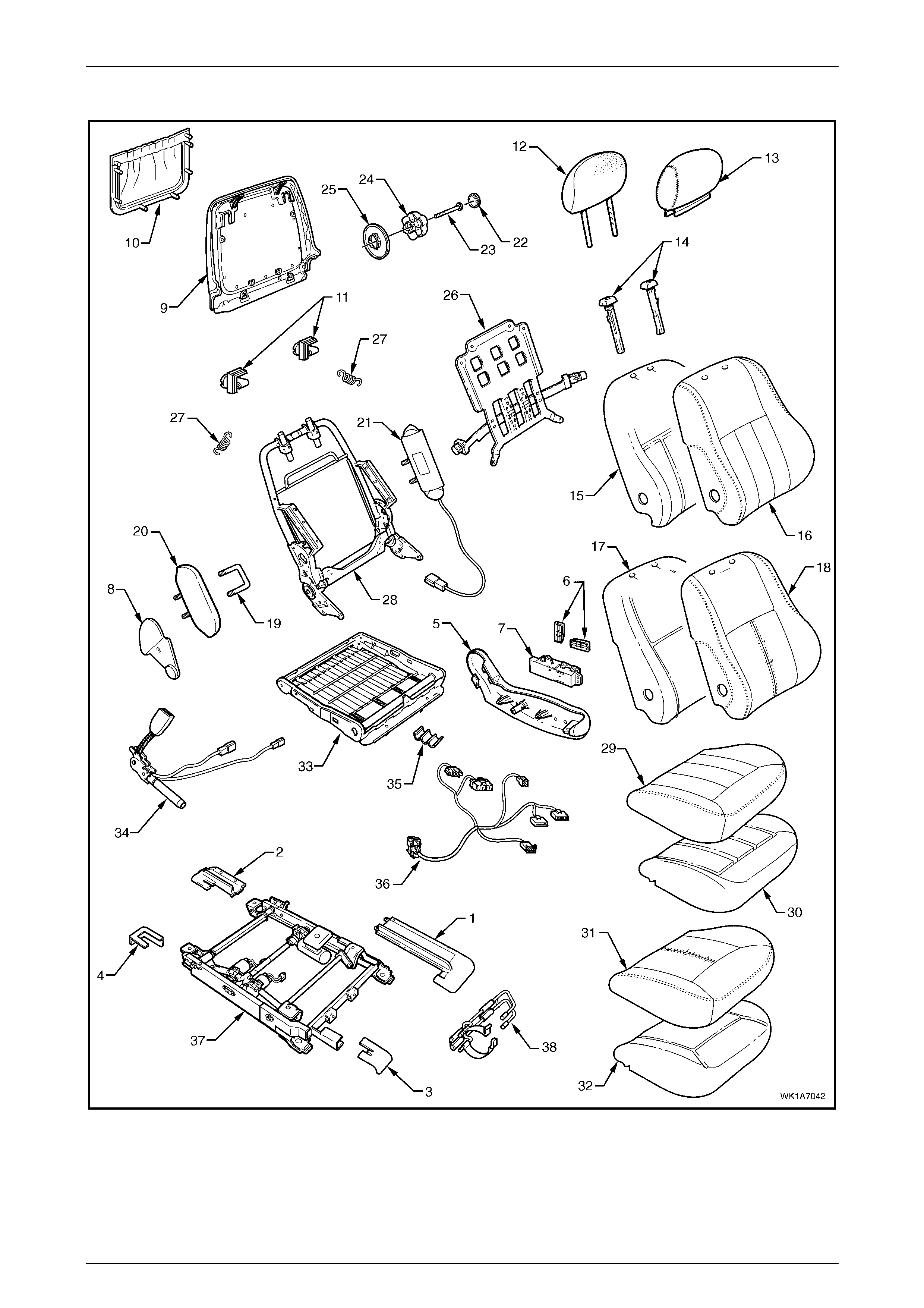
Seat Assemblies Page 1A7–104
Page 1A7–104
Front Seat Type 7
Figure 1A7 – 74

Seat Assemblies Page 1A7–105
Page 1A7–105
Legend
1 Front Seat Outer Front Cover
2 Front Seat Outer Rear Cover
3 Front Seat Inner Front Cover
4 Front Seat Inner Rear Cover
5 Front Seat Outer Side Cover
6 Front Sea t Ad ju s t ment Switch Knobs
7 Front Seat Adjustment Switch – Eight-way
8 Front Seat Inner Side Cover
9 Front Seat-back Rear Cover
10 Front Seat-back Map Pocket
11 Front Seat-back Cover Retaining Clips
12 Front Seat Head Restraint Pad Assembly
13 Front Seat Head Restraint Cover
14 Front Seat Head Restraint Sleeves
15 Front Seat-back Pad – Cloth Cover
16 Front Seat-back Cl oth Cover
17 Front Seat-back Pad – Leather Cover
18 Front Seat-back Leat her Cover
19 Front Seat Dummy Block U-bolt
20 Front Seat Dummy Block Insert
21 Side Impact Airbag Assembly
22 Lumbar Support Knob Cover
23 Lumbar Support Knob Screw
24 Lumbar Support Knob
25 Lumbar Support Deflector Ring
26 Lumbar Support Assembly
27 Lumbar Support Retaining Spring
28 Front Seat-back Frame Assembly
29 Front Seat Cushion Clot h Cover
30 Front Seat Cushion Pad – Cloth Cover
31 Front Seat Cushion Leather Cover
32 Front Seat Cushion Pad – Leather Cover
33 Front Seat Cushion Frame Assembly
34 Seatbelt Buckle & Pretensioner Assembly
35 Wiring Harness Retaining Clip
36 Wiring Harness Assembly
37 Track and Height Adjust Assembl y
38 Fire Extinguisher Mounti ng Bracket
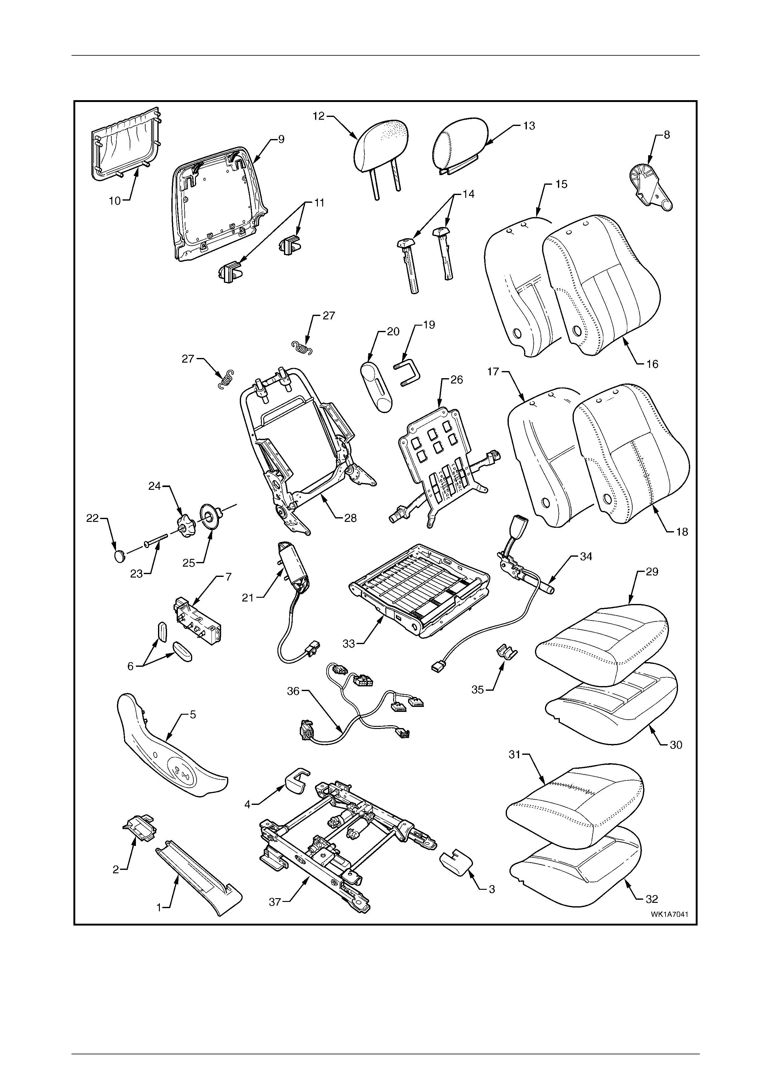
Seat Assemblies Page 1A7–106
Page 1A7–106
Front Seat Type 8
Figure 1A7 – 75

Seat Assemblies Page 1A7–107
Page 1A7–107
Legend
1 Front Seat Outer Front Cover
2 Front Seat Outer Rear Cover
3 Front Seat Inner Front Cover
4 Front Seat Inner Rear Cover
5 Front Seat Outer Side Cover
6 Front Sea t Ad ju s t ment Switch Knobs
7 Front Seat Adjustment Switch – Eight-way
8 Front Seat Inner Side Cover
9 Front Seat-back Rear Cover
10 Front Seat-back Map Pocket
11 Front Seat-back Cover Retaining Clips
12 Front Seat Head Restraint Pad Assembly
13 Front Seat Head Restraint Cover
14 Front Seat Head Restraint Sleeves
15 Front Seat-back Pad – Cloth Cover
16 Front Seat-back Cl oth Cover
17 Front Seat-back Pad – Leather Cover
18 Front Seat-back Leat her Cover
19 Front Seat Dummy Block U-bolt
20 Front Seat Dummy Block Insert
21 Side Impact Airbag Assembly
22 Lumbar Support Knob Cover
23 Lumbar Support Knob Screw
24 Lumbar Support Knob
25 Lumbar Support Deflector Ring
26 Lumbar Support Assembly
27 Lumbar Support Retaining Spring
28 Front Seat-back Frame Assembly
29 Front Seat Cushion Clot h Cover
30 Front Seat Cushion Pad – Cloth Cover
31 Front Seat Cushion Leather Cover
32 Front Seat Cushion Pad – Leather Cover
33 Front Seat Cushion Frame Assembly
34 Seatbelt Buckle & Pretensioner Assembly
35 Wiring Harness Retaining Clip
36 Wiring Harness Assembly
37 Track and Height Adjust Assembl y
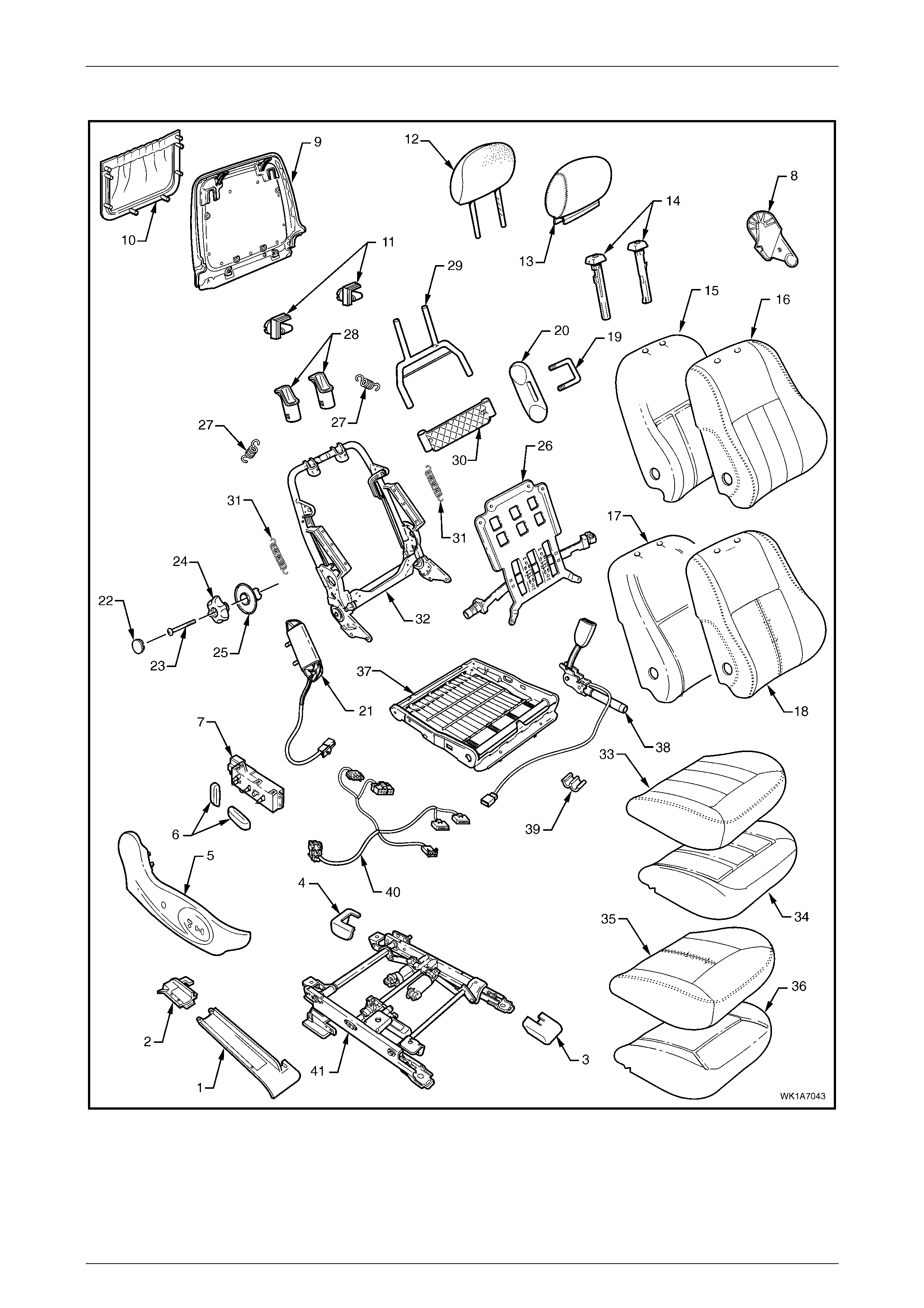
Seat Assemblies Page 1A7–108
Page 1A7–108
Front Seat Type 9
Figure 1A7 – 76

Seat Assemblies Page 1A7–109
Page 1A7–109
Legend
1 Front Seat Outer Front Cover
2 Front Seat Outer Rear Cover
3 Front Seat Inner Front Cover
4 Front Seat Inner Rear Cover
5 Front Seat Outer Side Cover
6 Front Sea t Ad ju s t ment Switch Knobs
7 Front Seat Adjustment Switch – Eight-way
8 Front Seat Inner Side Cover
9 Front Seat-back Rear Cover
10 Front Seat-back Map Pocket
11 Front Seat-back Cover Retaining Clips
12 Front Seat Head Restraint Pad Assembly
13 Front Seat Head Restraint Cover
14 Front Seat Head Restraint Sleeves
15 Front Seat-back Pad – Cloth Cover
16 Front Seat-back Cl oth Cover
17 Front Seat-back Pad – Leather Cover
18 Front Seat-back Leat her Cover
19 Front Seat Dummy Block U-bolt
20 Front Seat Dummy Block Insert
21 Side Impact Airbag Assembly
22 Lumbar Support Knob Cover
23 Lumbar Support Knob Screw
24 Lumbar Support Knob
25 Lumbar Support Deflector Ring
26 Lumbar Support Assembly
27 Lumbar Support Retaining Spring
28 Active Head Rest rai nt Fram e Sleeves
29 Active Head Rest rai nt Fram e Assembly
30 Active Head Rest rai nt Frame Support Strap
31 Active Head Rest rai nt Frame Retaining S pri ng
32 Front Seat-back Frame Assembly
33 Front Seat Cushion Clot h Cover
34 Front Seat Cushion Pad – Cloth Cover
35 Front Seat Cushion Leather Cover
36 Front Seat Cushion Pad – Leather Cover
37 Front Seat Cushion Frame Assembly
38 Seatbelt Buckle & Pretensioner Assembly
39 Wiring Harness Retaining Clip
40 Wiring Harness Assembly
41 Track and Height Adjust Assembl y
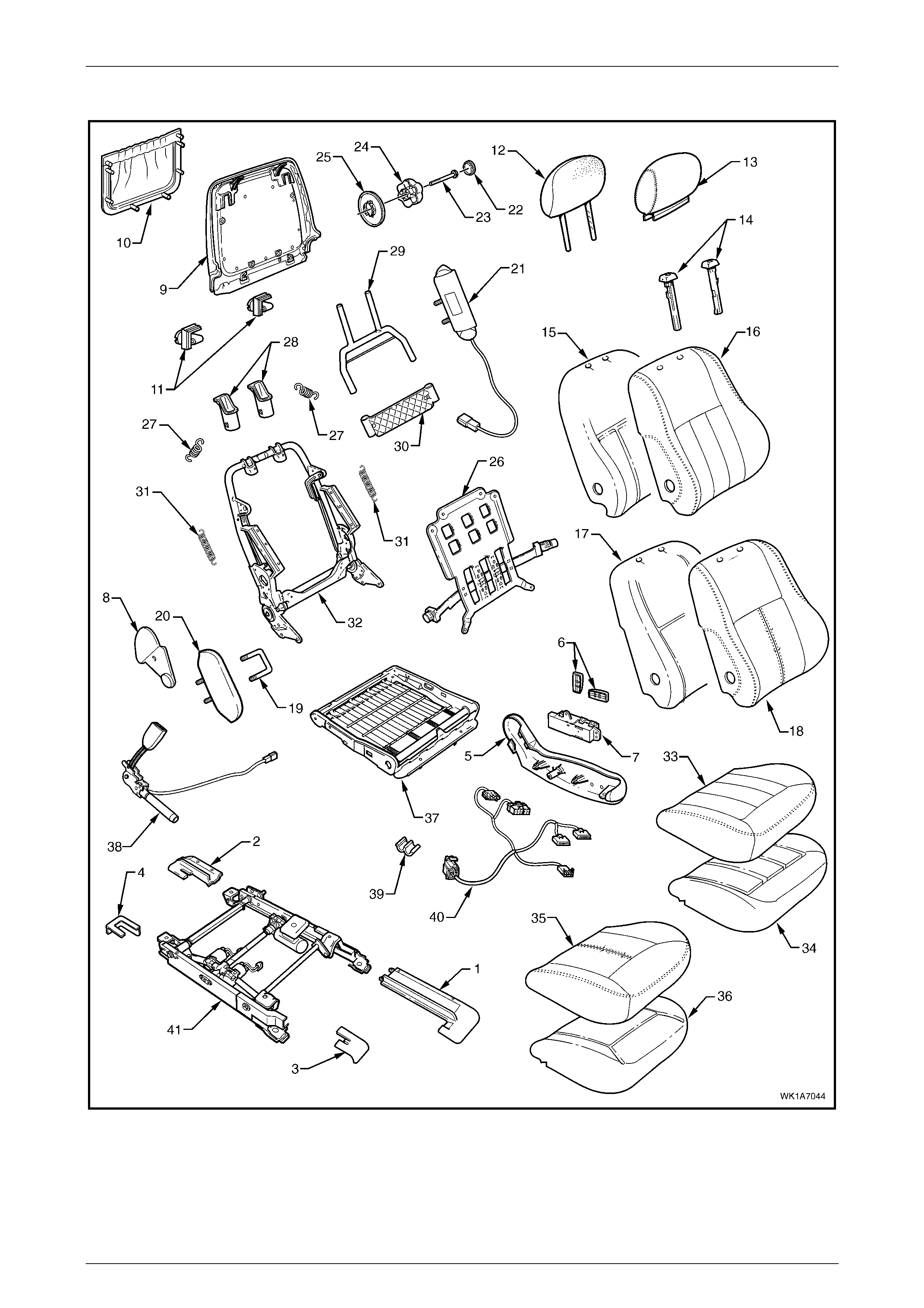
Seat Assemblies Page 1A7–110
Page 1A7–110
Front Seat Type 10
Figure 1A7 – 77

Seat Assemblies Page 1A7–111
Page 1A7–111
Legend
1 Front Seat Outer Front Cover
2 Front Seat Outer Rear Cover
3 Front Seat Inner Front Cover
4 Front Seat Inner Rear Cover
5 Front Seat Outer Side Cover
6 Front Sea t Ad ju s t ment Switch Knobs
7 Front Seat Adjustment Switch – Eight-way
8 Front Seat Inner Side Cover
9 Front Seat-back Rear Cover
10 Front Seat-back Map Pocket
11 Front Seat-back Cover Retaining Clips
12 Front Seat Head Restraint Pad Assembly
13 Front Seat Head Restraint Cover
14 Front Seat Head Restraint Sleeves
15 Front Seat-back Pad – Cloth Cover
16 Front Seat-back Cl oth Cover
17 Front Seat-back Pad – Leather Cover
18 Front Seat-back Leat her Cover
19 Front Seat Dummy Block u-bolt
20 Front Seat Dummy Block Insert
21 Side Impact Airbag Assembly
22 Lumbar Support Knob Cover
23 Lumbar Support Knob Screw
24 Lumbar Support Knob
25 Lumbar Support Deflector Ring
26 Lumbar Support Assembly
27 Lumbar Support Retaining Spring
28 Active Head Rest rai nt Fram e Sleeves
29 Active Head Rest rai nt Fram e Assembly
30 Active Head Rest rai nt Frame Support Strap
31 Active Head Rest rai nt Frame Retaining S pri ng
32 Front Seat-back Frame Assembly
33 Front Seat Cushion Clot h Cover
34 Front Seat Cushion Pad – Cloth Cover
35 Front Seat Cushion Leather Cover
36 Front Seat Cushion Pad – Leather Cover
37 Front Seat Cushion Frame Assembly
38 Seatbelt Buckle & Pretensioner Assembly
39 Wiring Harness Retaining Clip
40 Wiring Harness Assembly
41 Track and Height Adjust Assembl y
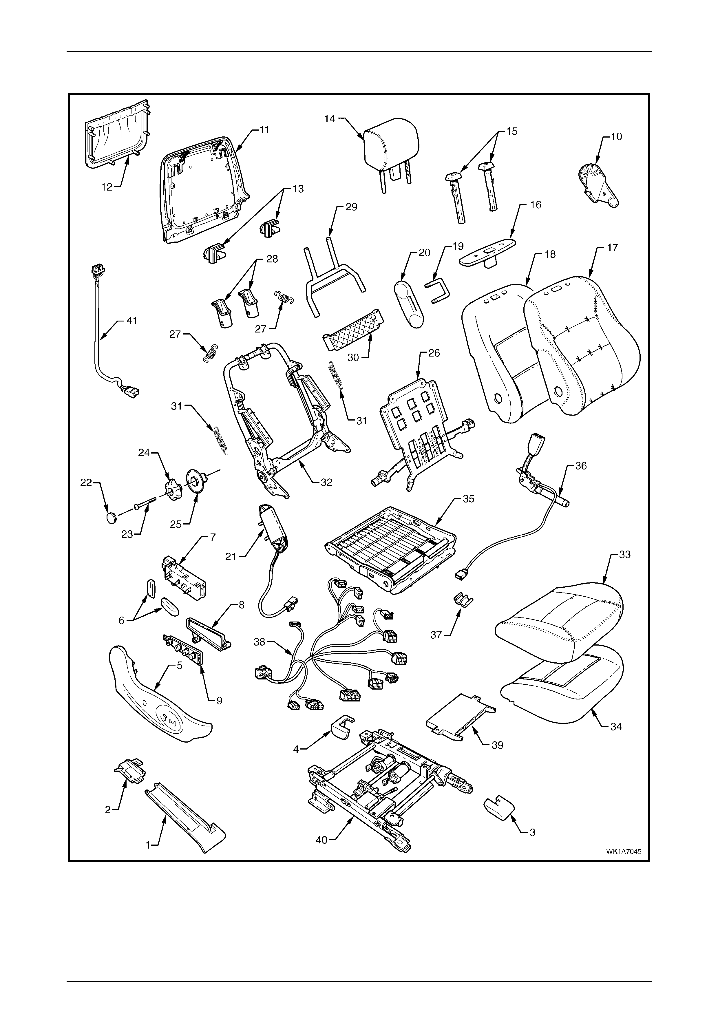
Seat Assemblies Page 1A7–112
Page 1A7–112
Front Seat Type 11
Figure 1A7 – 78

Seat Assemblies Page 1A7–113
Page 1A7–113
Legend
1 Front Seat Outer Front Cover
2 Front Seat Outer Rear Cover
3 Front Seat Inner Front Cover
4 Front Seat Inner Rear Cover
5 Front Seat Outer Side Cover
6 Front Sea t Ad ju s t ment Switch Knobs
7 Front Seat Adjustment Switch – Eight-way
8 Memory Posi tion Switc h Cover
9 Memory Po sition Switch Assembly
10 Front Seat Inner Side Cover
11 Front Seat-back Rear Cover
12 Front Seat-back Map Pocket
13 Front Seat-back Cover Retaining Clips
14 Front Seat Head Restraint Assembly*
15 Front Seat Head Restraint Sleeves
16 Front Seat Head Restraint Guide Cover
17 Front Seat-back Cover
18 Front Seat-back Pad
19 Front Seat Dummy Block U-bolt
20 Front Seat Dummy Block Insert
21 Side Impact Airbag Assembly
22 Lumbar Support Knob Cover
23 Lumbar Support Knob Screw
24 Lumbar Support Knob
25 Lumbar Support Deflector Ring
26 Lumbar Support Assembly
27 Lumbar Support Retaining Spring
28 Active Head Rest rai nt Fram e Sleeves
29 Active Head Rest rai nt Fram e Assembly
30 Active Head Rest rai nt Frame Support Strap
31 Active Head Rest rai nt Frame Retaining S pri ng
32 Front Seat-back Frame Assembly
33 Front Seat Cushion Cover
34 Front Seat Cushion Pad
35 Front Seat Cushion Frame Assembly
36 Seatbelt Buckle & Pretensioner Assembly
37 Wiring Harness Retaining Clip
38 Wiring Harness Assembly
39 Seat Memory Module
40 Track and Height Adjust Assembl y
41 Rear Seat Entertainment Lower Wiring Harness Assembly
* Refer to Figure 1A7 – 88 for the front head restraint assembly components.
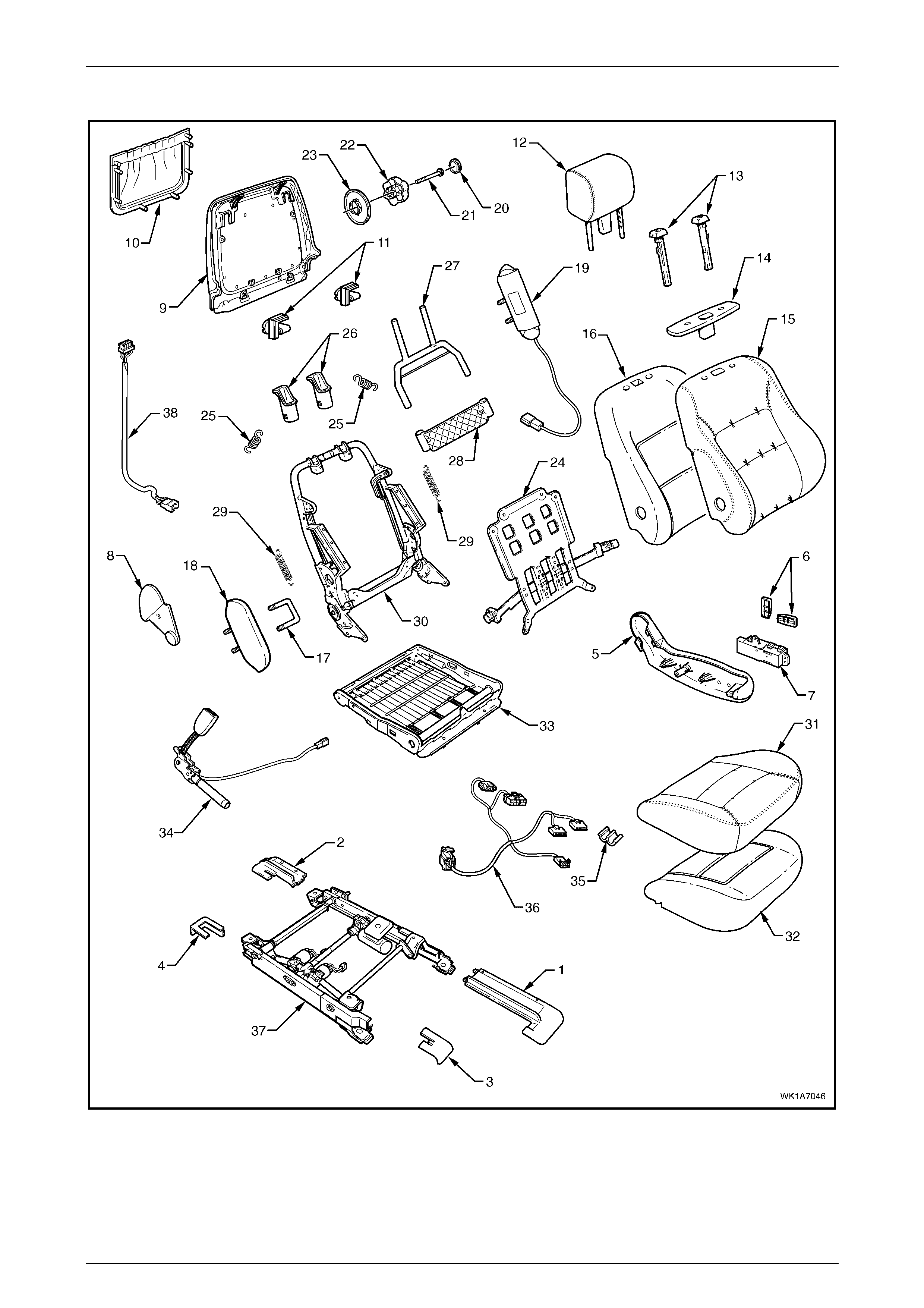
Seat Assemblies Page 1A7–114
Page 1A7–114
Front Seat Type 12
Figure 1A7 – 79

Seat Assemblies Page 1A7–115
Page 1A7–115
Legend
1 Front Seat Outer Front Cover
2 Front Seat Outer Rear Cover
3 Front Seat Inner Front Cover
4 Front Seat Inner Rear Cover
5 Front Seat Outer Side Cover
6 Front Sea t Ad ju s t ment Switch Knobs
7 Front Seat Adjustment Switch – Eight-way
8 Front Seat Inner Side Cover
9 Front Seat-back Rear Cover
10 Front Seat-back Map Pocket
11 Front Seat-back Cover Retaining Clips
12 Front Seat Head Restraint Assembly*
13 Front Seat Head Restraint Sleeves
14 Front Seat Head Restraint Guide Cover
15 Front Seat-back Cover
16 Front Seat-back Pad Cover
17 Front Seat Dummy Block U-bolt
18 Front Seat Dummy Block Insert
19 Side Impact Airbag Assembly
20 Lumbar Support Knob Cover
21 Lumbar Support Knob Screw
22 Lumbar Support Knob
23 Lumbar Support Deflector Ring
24 Lumbar Support Assembly
25 Lumbar Support Retaining Spring
26 Active Head Rest rai nt Fram e Sleeves
27 Active Head Rest rai nt Fram e Assembly
28 Active Head Rest rai nt Frame Support Strap
29 Active Head Rest rai nt Frame Retaining S pri ng
30 Front Seat-back Frame Assembly
31 Front Seat Cushion Cover
32 Front Seat Cushion Pad
33 Front Seat Cushion Frame Assembly
34 Seatbelt Buckle & Pretensioner Assembly
35 Wiring Harness Retaining Clip
36 Wiring Harness Assembly
37 Track and Height Adjust Assembl y
38 Rear Seat Entertainment Lower Wiring Harness Assembly
* Refer to Figure 1A7 – 88 for the front head restraint assembly components.
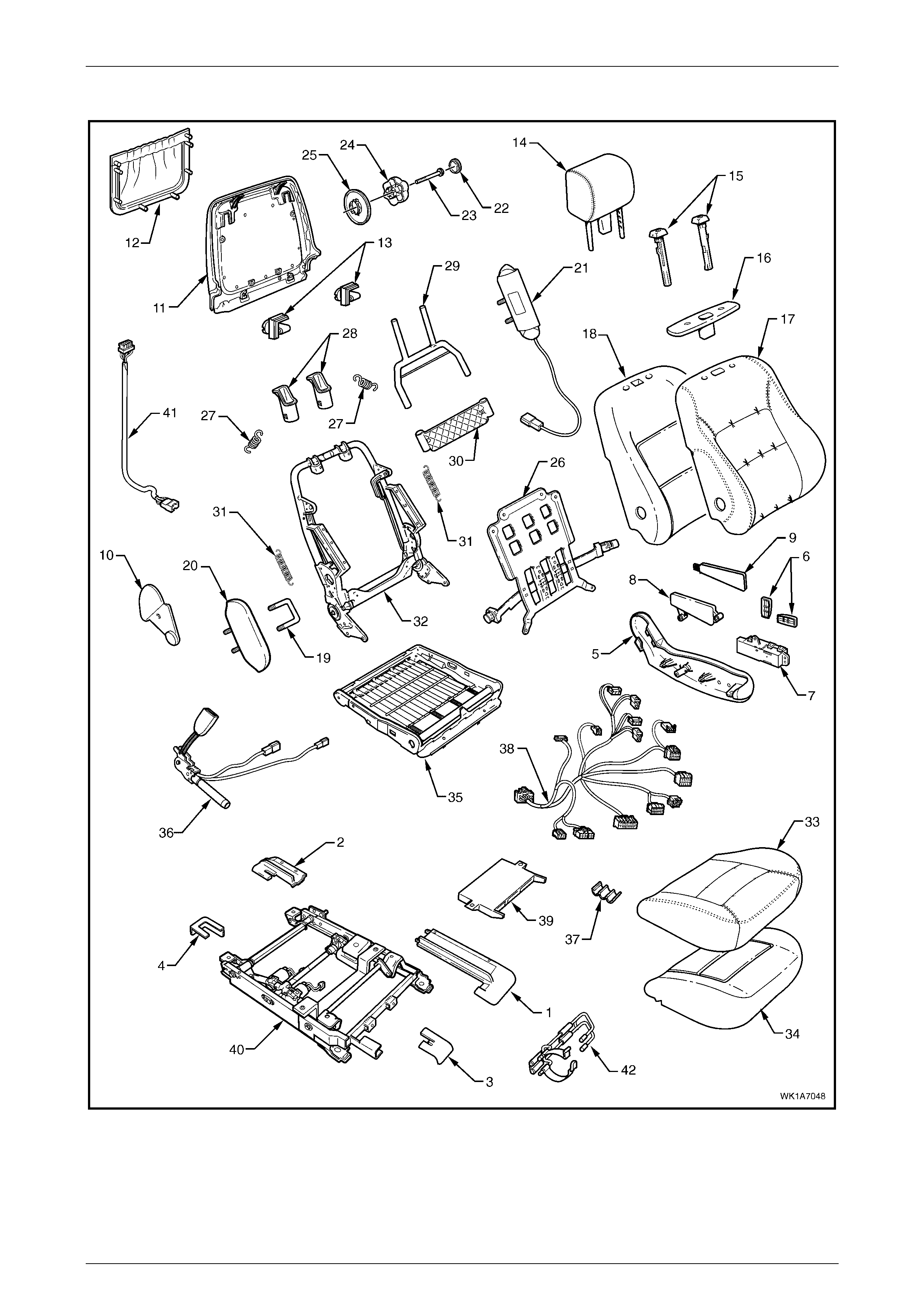
Seat Assemblies Page 1A7–116
Page 1A7–116
Front Seat Type 13
Figure 1A7 – 80

Seat Assemblies Page 1A7–117
Page 1A7–117
Legend
1 Front Seat Outer Front Cover
2 Front Seat Outer Rear Cover
3 Front Seat Inner Front Cover
4 Front Seat Inner Rear Cover
5 Front Seat Outer Side Cover
6 Front Sea t Ad ju s t ment Switch Knobs
7 Front Seat Adjustment Switch – Eight-way
8 Memory Posi tion Switc h Cover
9 Memory Po sition Switch Assembly
10 Front Seat Inner Side Cover
11 Front Seat-back Rear Cover
12 Front Seat-back Map Pocket
13 Front Seat-back Cover Retaining Clips
14 Front Seat Head Restraint Assembly*
15 Front Seat Head Restraint Sleeves
16 Front Seat Head Restraint Guide Cover
17 Front Seat-back Cover
18 Front Seat-back Pad
19 Front Seat Dummy Block U-bolt
20 Front Seat Dummy Block Insert
21 Side Impact Airbag Assembly
22 Lumbar Support Knob Cover
23 Lumbar Support Knob Screw
24 Lumbar Support Knob
25 Lumbar Support Deflector Ring
26 Lumbar Support Assembly
27 Lumbar Support Retaining Spring
28 Active Head Rest rai nt Fram e Sleeves
29 Active Head Rest rai nt Fram e Assembly
30 Active Head Rest rai nt Frame Support Strap
31 Active Head Rest rai nt Frame Retaining S pri ng
32 Front Seat-back Frame Assembly
33 Front Seat Cushion Cover
34 Front Seat Cushion Pad
35 Front Seat Cushion Frame Assembly
36 Seatbelt Buckle & Pretensioner Assembly
37 Wiring Harness Retaining Clip
38 Wiring Harness Assembly
39 Seat Memory Module
40 Track and Height Adjust Assembl y
41 Rear Seat Entertainment Lower Wiring Harness Assembly
42 Fire Extinguisher Mounti ng Bracket
* Refer to Figure 1A7 – 88 for the front head restraint assembly components.
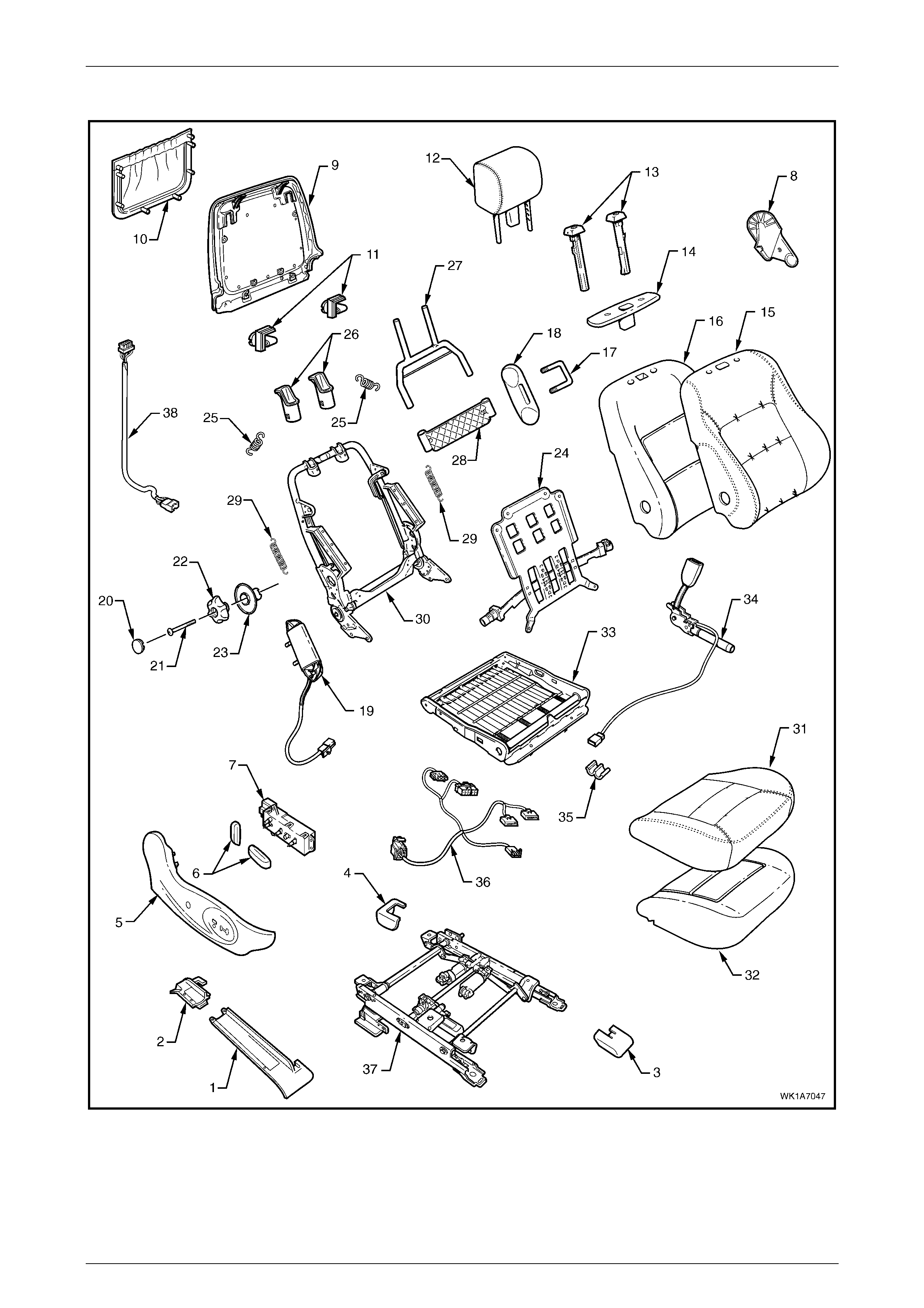
Seat Assemblies Page 1A7–118
Page 1A7–118
Front Seat Type 14
Figure 1A7 – 81

Seat Assemblies Page 1A7–119
Page 1A7–119
Legend
1 Front Seat Outer Front Cover
2 Front Seat Outer Rear Cover
3 Front Seat Inner Front Cover
4 Front Seat Inner Rear Cover
5 Front Seat Outer Side Cover
6 Front Sea t Ad ju s t ment Switch Knobs
7 Front Seat Adjustment Switch – Eight-way
8 Front Seat Inner Side Cover
9 Front Seat-back Rear Cover
10 Front Seat-back Map Pocket
11 Front Seat-back Cover Retaining Clips
12 Front Seat Head Restraint Assembly*
13 Front Seat Head Restraint Sleeves
14 Front Seat Head Restraint Guide Cover
15 Front Seat-back Cover
16 Front Seat-back Pad Cover
17 Front Seat Dummy Block U-bolt
18 Front Seat Dummy Block Insert
19 Side Impact Airbag Assembly
20 Lumbar Support Knob Cover
21 Lumbar Support Knob Screw
22 Lumbar Support Knob
23 Lumbar Support Deflector Ring
24 Lumbar Support Assembly
25 Lumbar Support Retaining Spring
26 Active Head Rest rai nt Fram e Sleeves
27 Active Head Rest rai nt Fram e Assembly
28 Active Head Rest rai nt Frame Support Strap
29 Active Head Rest rai nt Frame Retaining S pri ng
30 Front Seat-back Frame Assembly
31 Front Seat Cushion Cover
32 Front Seat Cushion Pad
33 Front Seat Cushion Frame Assembly
34 Seatbelt Buckle & Pretensioner Assembly
35 Wiring Harness Retaining Clip
36 Wiring Harness Assembly
37 Track and Height Adjust Assembl y
38 Rear Seat Entertainment Lower Wiring Harness Assembly
* Refer to Figure 1A7 – 88 for the front head restraint assembly components.
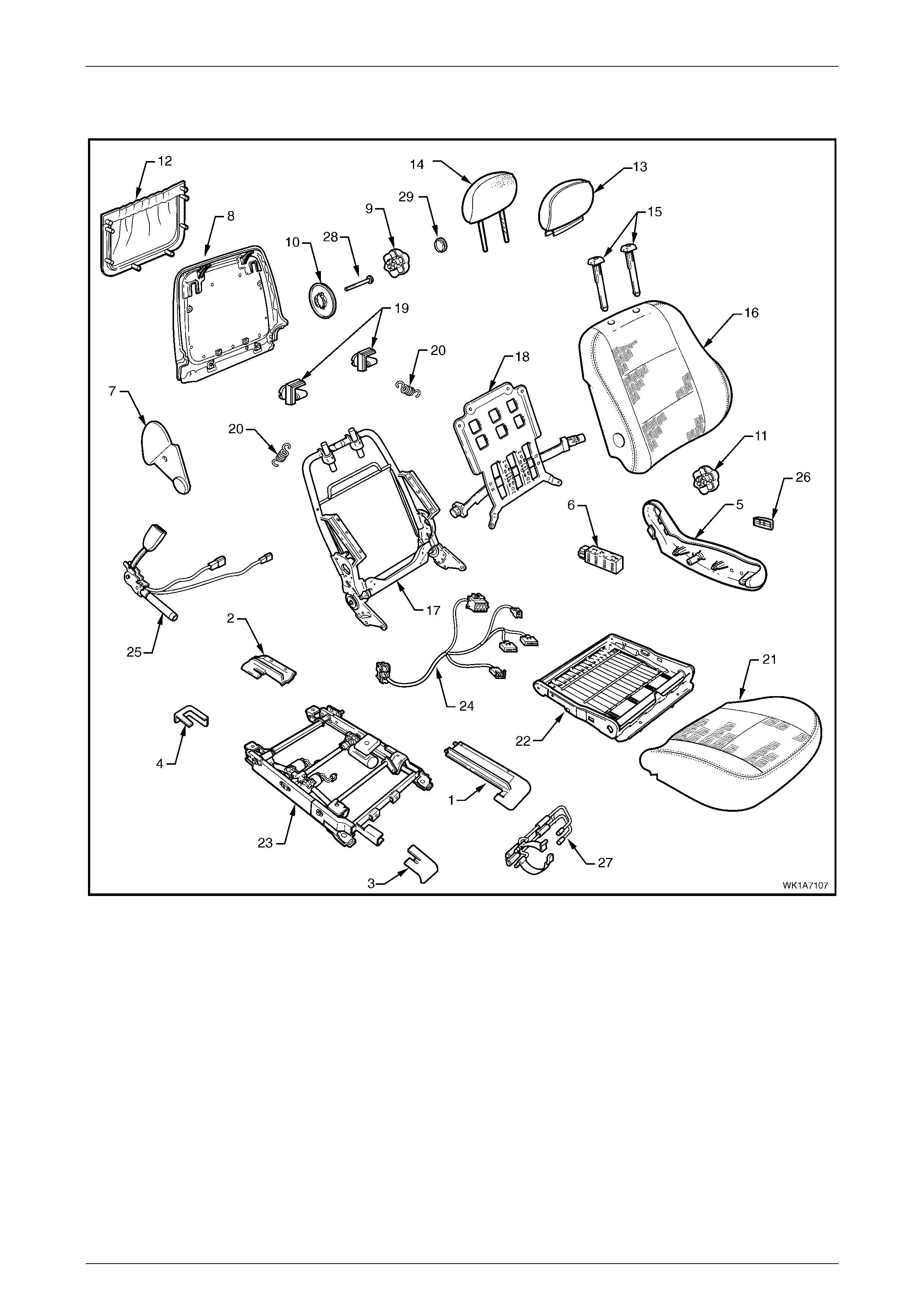
Seat Assemblies Page 1A7–120
Page 1A7–120
Front Seat Type 15
Figure 1A7 – 82

Seat Assemblies Page 1A7–121
Page 1A7–121
Legend
1 Front Seat Outer Front Cover
2 Front Seat Outer Rear Cover
3 Front Seat Inner Front Cover
4 Front Seat Inner Rear Cover
5 Front Seat Outer Side Cover
6 Front Sea t Adju stment Switch – Six-w a y
7 Front Seat Inner Side Cover
8 Front Seat-back Rear Cover
9 Lumbar Support Knob
10 Lumber Support Deflector Ring
11 Recline Adjuster Knob
12 Front Seat-back Map Pocket
13 Front Seat Head Restraint Cover
14 Front Seat Head Restraint Pad Assembly
15 Front Seat Head Restraint Sleeves
16 Front Seat-back Cover and Pad Assembly
17 Front Seat-back Frame Assembly
18 Lumbar Support Assembly
19 Front Seat-back Cover Retaining Clip
20 Lumbar Support Retaining Spring
21 Front Seat Cushion Cover and Pad
22 Front Seat Cushion Frame Assembly
23 Track and Height Adjust Assembl y
24 Wiring Harness Assembly
25 Seatbelt Buckle & Pretensioner Assembly
26 Front Seat Adjustment Switch Knob
27 Fire Extinguisher Mounti ng Bracket
28 Lumbar Support Knob Screw
29 Lumbar Support Knob Cover
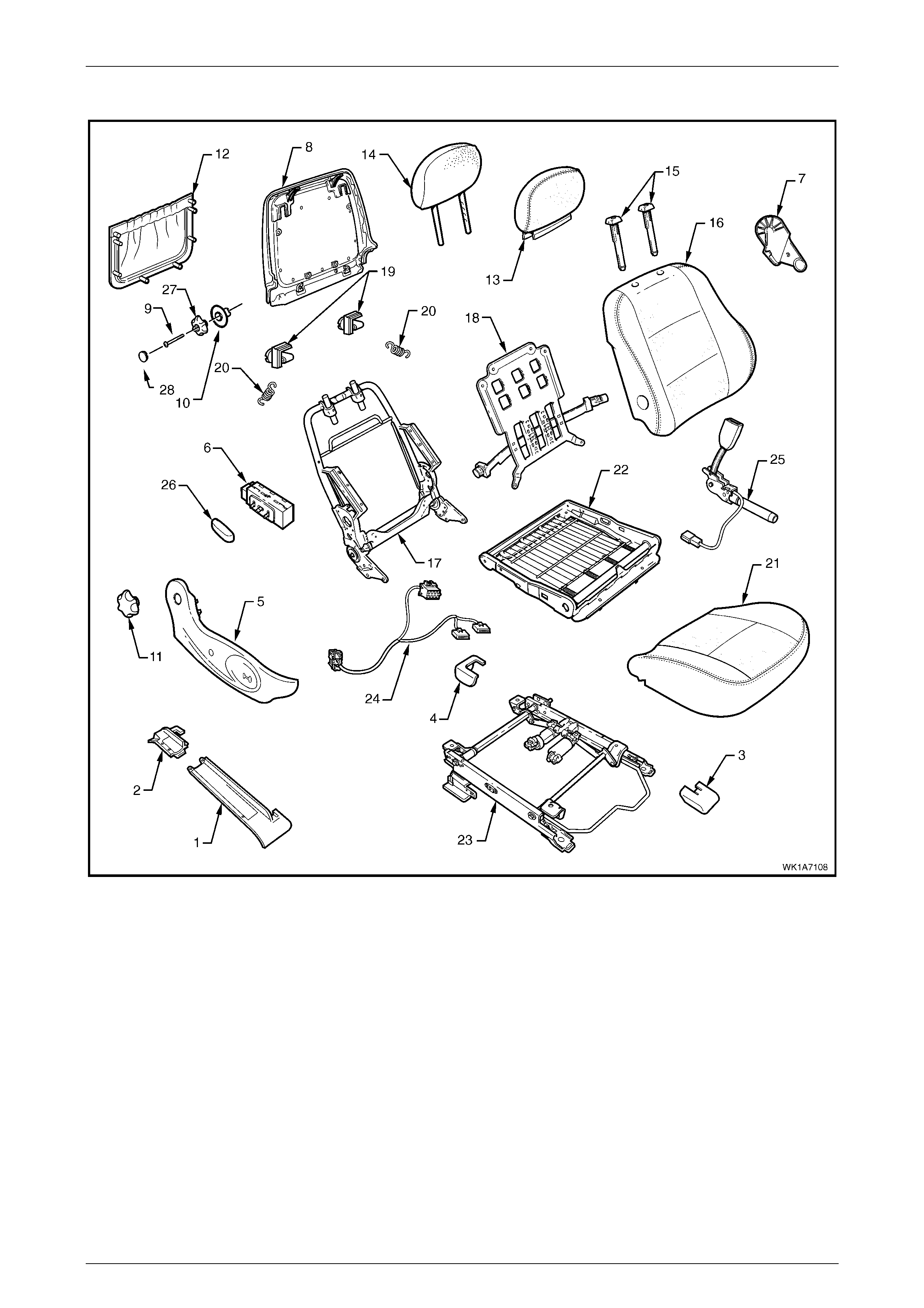
Seat Assemblies Page 1A7–122
Page 1A7–122
Front Seat Type 16
Figure 1A7 – 83
Legend
1 Front Seat Outer Front Cover
2 Front Seat Outer Rear Cover
3 Front Seat Inner Front Cover
4 Front Seat Inner Rear Cover
5 Front Seat Outer Side Cover
6 Front Seat Adjustment Switch – Four-way
7 Front Seat Inner Side Cover
8 Front Seat-back Rear Cover
9 Lumbar Support Knob
10 Lumber Support Deflector Ring
11 Recline Adjuster Knob
12 Front Seat-back Map Pocket
13 Front Seat Head Restraint Cover
14 Front Seat Head Restraint Pad Assembly
15 Front Seat Head Restraint Sleeves
16 Front Seat-back Cover and Pad Assembly
17 Front Seat-back Frame Assembly
18 Lumbar Support Assembly
19 Front Seat-back Cover retaining Clip
20 Lumbar Support Retaining Spring
21 Front Seat Cushion Cover and Pad
22 Front Seat Cushion Frame Assembly
23 Track and Height Adjust Assembl y
24 Wiring Harness Assembly
25 Seatbelt Buckle & Pretensioner Assembly
26 Front Seat Adjustment Switch Knob
27 Lumbar Support Knob Screw
28 Lumbar Support Knob Cover
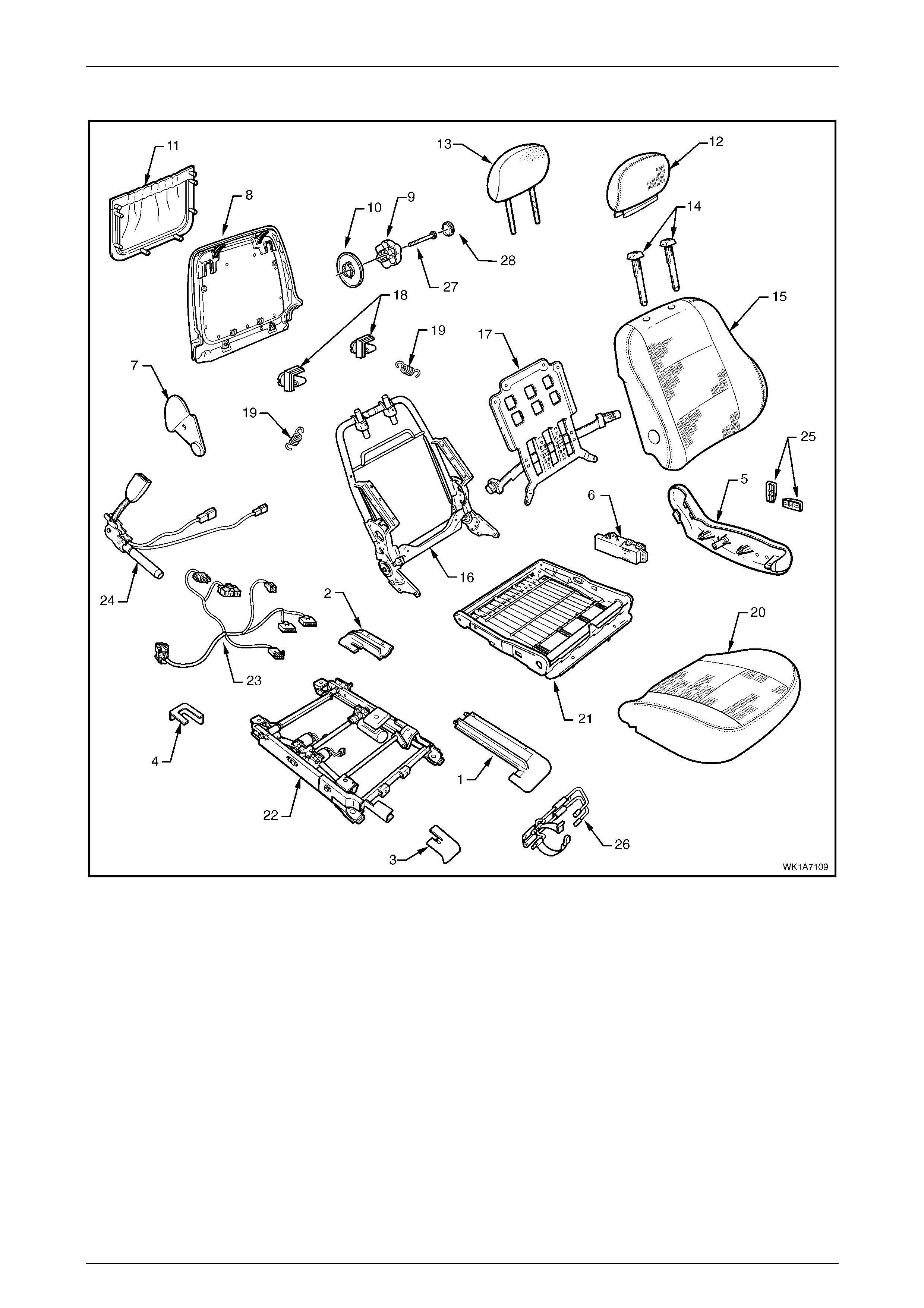
Seat Assemblies Page 1A7–123
Page 1A7–123
Front Seat Type 17
Figure 1A7 – 84
Legend
1 Front Seat Outer Front Cover
2 Front Seat Outer Rear Cover
3 Front Seat Inner Front Cover
4 Front Seat Inner Rear Cover
5 Front Seat Outer Side Cover
6 Front Seat Adjustment Switch – Eight-way
7 Front Seat Inner Side Cover
8 Front Seat-back Rear Cover
9 Lumbar Support Knob
10 Lumber Support Deflector Ring
11 Front Seat-back Map Pocket
12 Front Seat Head Restraint Cover
13 Front Seat Head Restraint Pad Assembly
14 Front Seat Head Restraint Sleeves
15 Front Seat-back Cover and Pad Assembly
16 Front Seat-back Frame Assembly
17 Lumbar Support Assembly
18 Front Seat-back Cover retaining Clip
19 Lumbar Support Retaining Spring
20 Front Seat Cushion Cover and Pad
21 Front Seat Cushion Frame Assembly
22 Track and Height Adjust Assembl y
23 Wiring Harness Assembly
24 Seatbelt Buckle & Pretensioner Assembly
25 Front Seat Adjustmen t Switch Knobs
26 Fire Extinguisher Mounti ng Bracket
27 Lumbar Support Knob Screw
28 Lumbar Support Knob Cover
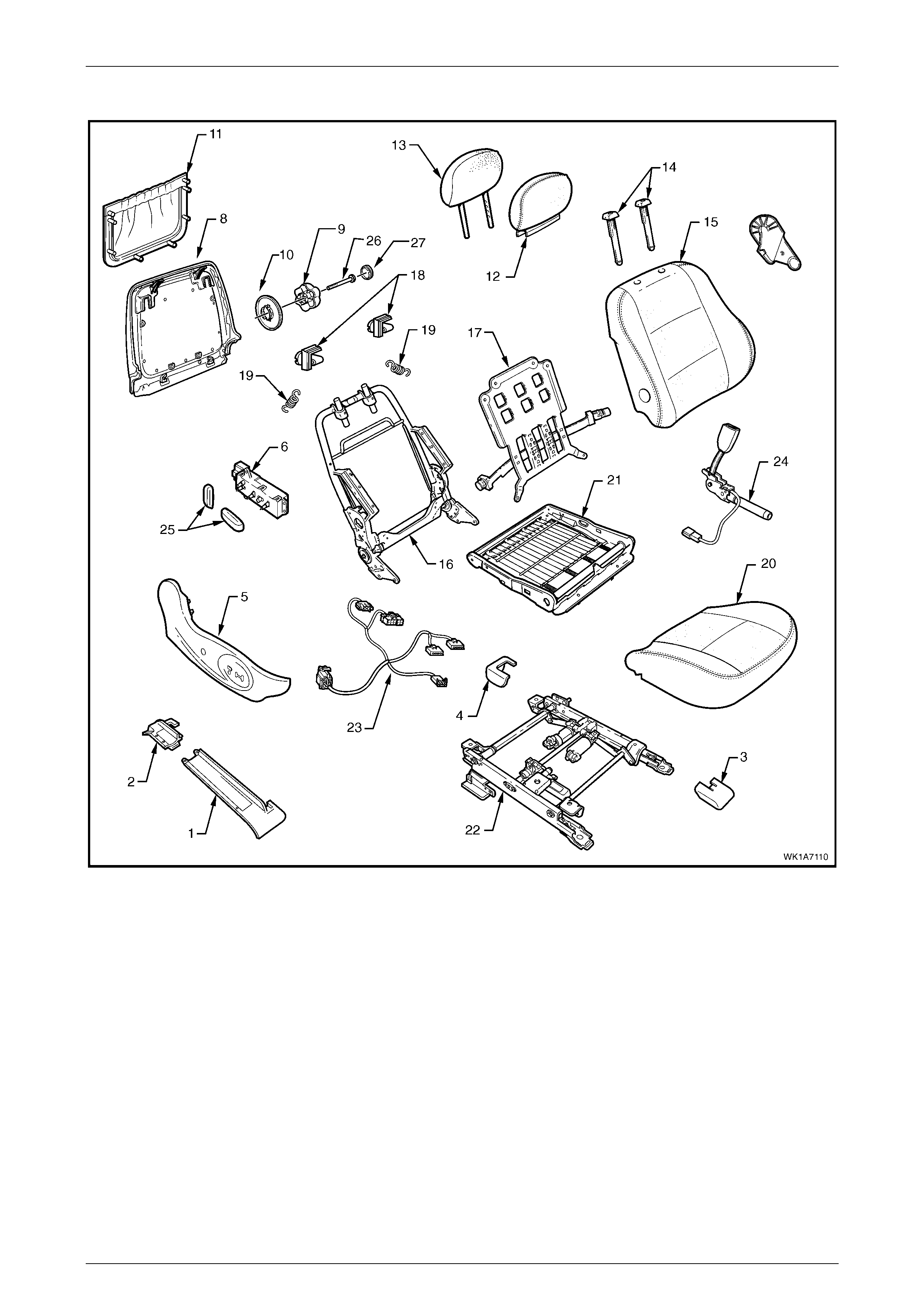
Seat Assemblies Page 1A7–124
Page 1A7–124
Front Seat Type 18
Figure 1A7 – 85
Legend
1 Front Seat Outer Front Cover
2 Front Seat Outer Rear Cover
3 Front Seat Inner Front Cover
4 Front Seat Inner Rear Cover
5 Front Seat Outer Side Cover
6 Front Seat Adjustment Switch – Eight-way
7 Front Seat Inner Side Cover
8 Front Seat-back Rear Cover
9 Lumbar Support Knob
10 Lumber Support Deflector Ring
11 Front Seat-back Map Pocket
12 Front Seat Head Restraint Cover
13 Front Seat Head Restraint Pad Assembly
14 Front Seat Head Restraint Sleeves
15 Front Seat-back Cover and Pad Assembly
16 Front Seat-back Frame Assembly
17 Lumbar Support Assembly
18 Front Seat-back Cover retaining Clip
19 Lumbar Support Retaining Spring
20 Front Seat Cushion Cover and Pad
21 Front Seat Cushion Frame Assembly
22 Track and Height Adjust Assembl y
23 Wiring Harness Assembly
24 Seatbelt Buckle & Pretensioner Assembly
25 Front Seat Adjustmen t Switch Knobs
26 Lumbar Support Knob Screw
27 Lumbar Support Knob Cover
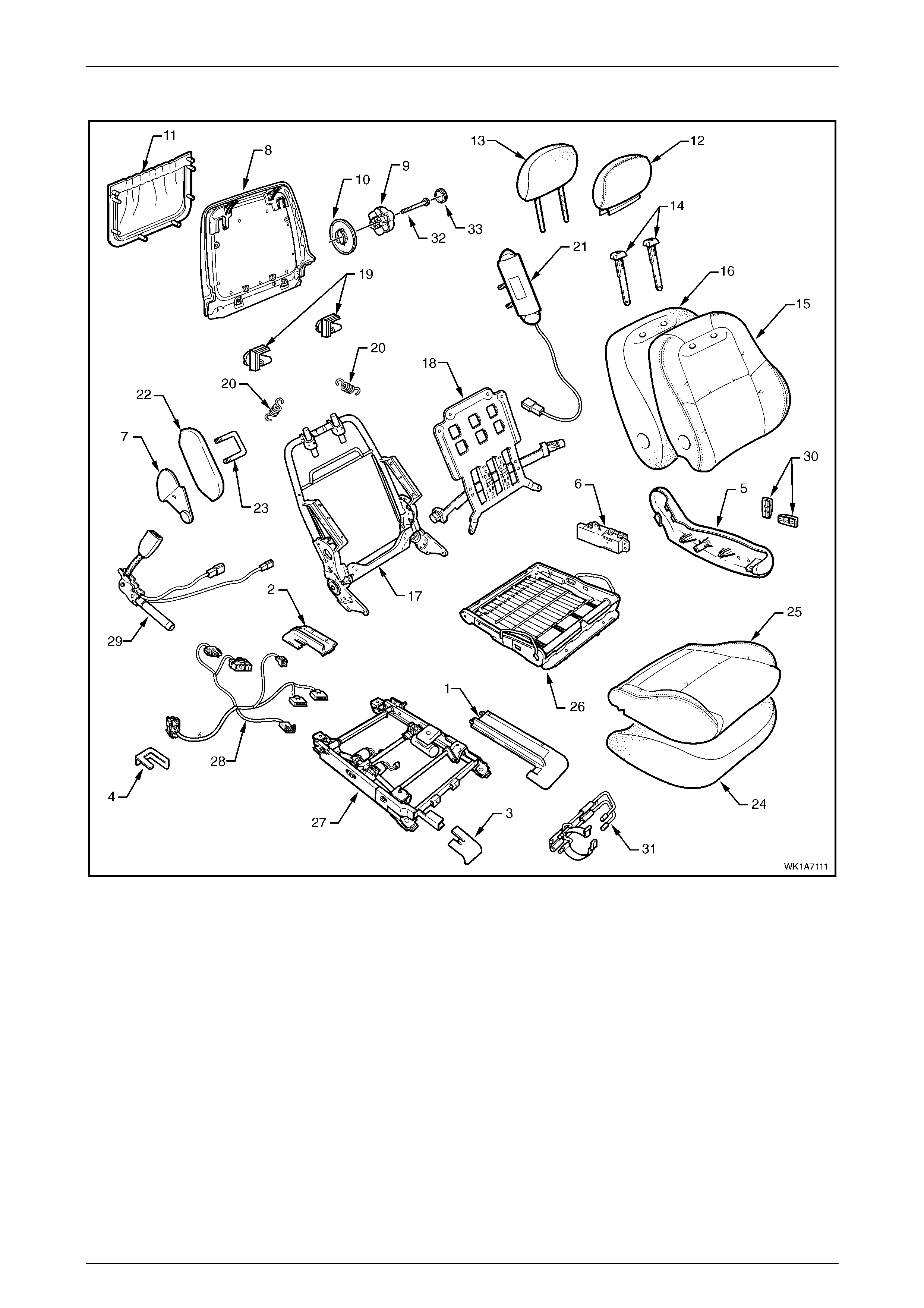
Seat Assemblies Page 1A7–125
Page 1A7–125
Front Seat Type 19
Figure 1A7 – 86

Seat Assemblies Page 1A7–126
Page 1A7–126
Legend
1 Front Seat Outer Front Cover
2 Front Seat Outer Rear Cover
3 Front Seat Inner Front Cover
4 Front Seat Inner Rear Cover
5 Front Seat Outer Side Cover
6 Front Seat Adjustment Switch – Eight-way
7 Front Seat Inner Side Cover
8 Front Seat-back Rear Cover
9 Lumbar Support Knob
10 Lumber Support Deflector Ring
11 Front Seat-back Map Pocket
12 Front Seat Head Restraint Cover
13 Front Seat Head Restraint Pad Assembly
14 Front Seat Head Restraint Sleeves
15 Front Seat-back Cover
16 Front Seat-back Pad
17 Front Seat-back Frame Assembly
18 Lumbar Support Assembly
19 Front Seat-back Cover retaining Clip
20 Lumbar Support Retaining Spring
21 Side Impact Airbag Assembly
22 Front Seat Dummy Block Insert
23 Front Seat Dummy Block U-bolt
24 Front Seat Cushion Pad
25 Front Seat Cushion Cover
26 Front Seat Cushion Frame Assembly
27 Track and Height Adjust Assembl y
28 Wiring Harness Assembly
29 Seatbelt Buckle & Pretensioner Assembly
30 Front Seat Adjustmen t Switch Knobs
31 Fire Extinguisher Mounti ng Bracket
32 Lumbar Support Knob Screw
27 Lumbar Support Knob Cover
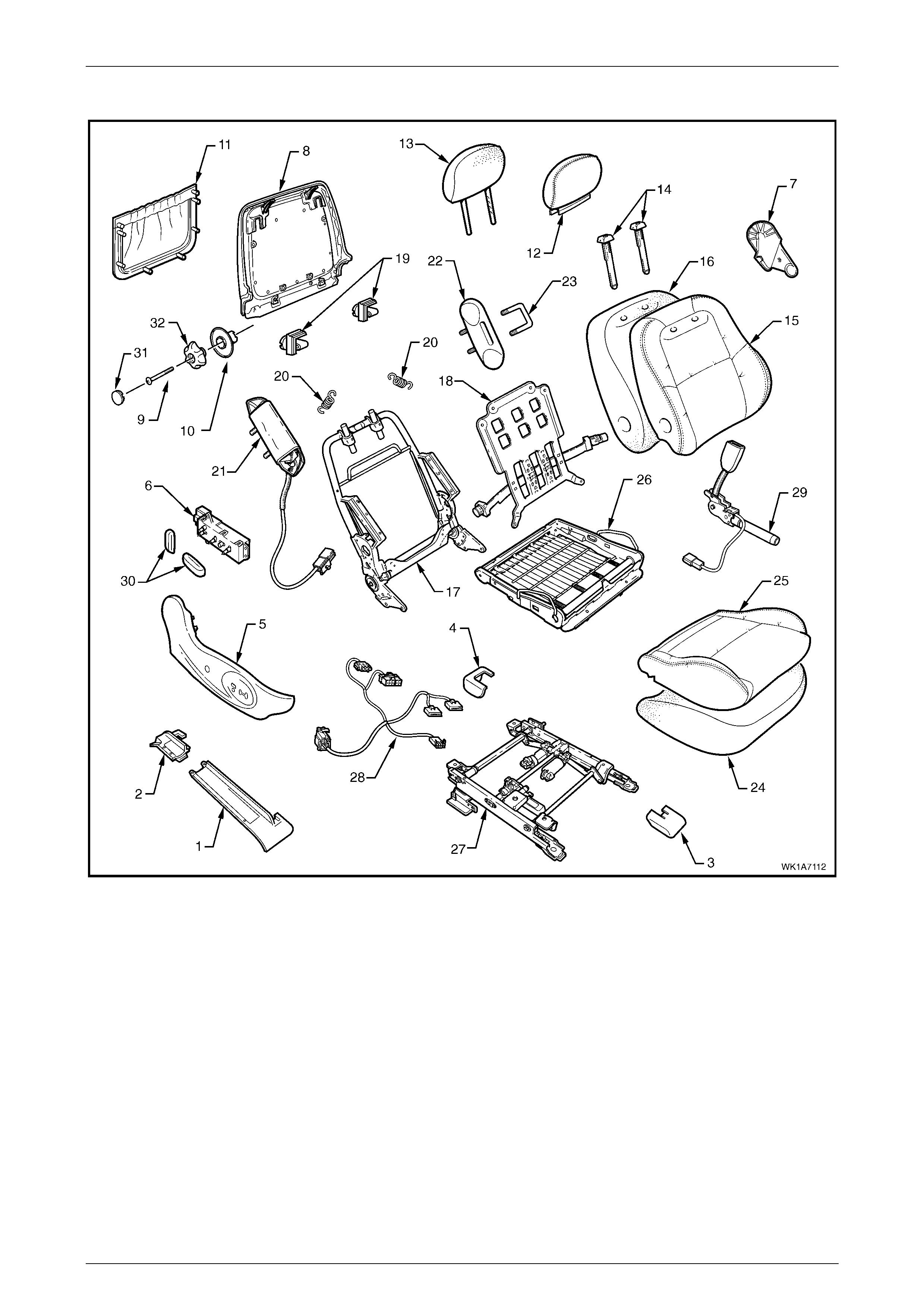
Seat Assemblies Page 1A7–127
Page 1A7–127
Front Seat Type 20
Figure 1A7 – 87

Seat Assemblies Page 1A7–128
Page 1A7–128
Legend
1 Front Seat Outer Front Cover
2 Front Seat Outer Rear Cover
3 Front Seat Inner Front Cover
4 Front Seat Inner Rear Cover
5 Front Seat Outer Side Cover
6 Front Seat Adjustment Switch – Eight-way
7 Front Seat Inner Side Cover
8 Front Seat-back Rear Cover
9 Lumbar Support Knob
10 Lumber Support Deflector Ring
11 Front Seat-back Map Pocket
12 Front Seat Head Restraint Cover
13 Front Seat Head Restraint Pad Assembly
14 Front Seat Head Restraint Sleeves
15 Front Seat-back Cover
16 Front Seat-back Pad
17 Front Seat-back Frame Assembly
18 Lumbar Support Assembly
19 Front Seat-back Cover Retaining Clip
20 Lumbar Support Retaining Spring
21 Side Impact Airbag Assembly
22 Front Seat Dummy Block Insert
23 Front Seat Dummy Block U-bolt
24 Front Seat Cushion Pad
25 Front Seat Cushion Cover
26 Front Seat Cushion Frame Assembly
27 Track and Height Adjust Assembl y
28 Wiring Harness Assembly
29 Seatbelt Buckle & Pretensioner Assembly
30 Front Seat Adjustmen t Switch Knobs
32 Lumbar Support Knob Cover
27 Lumbar Support Knob Screw
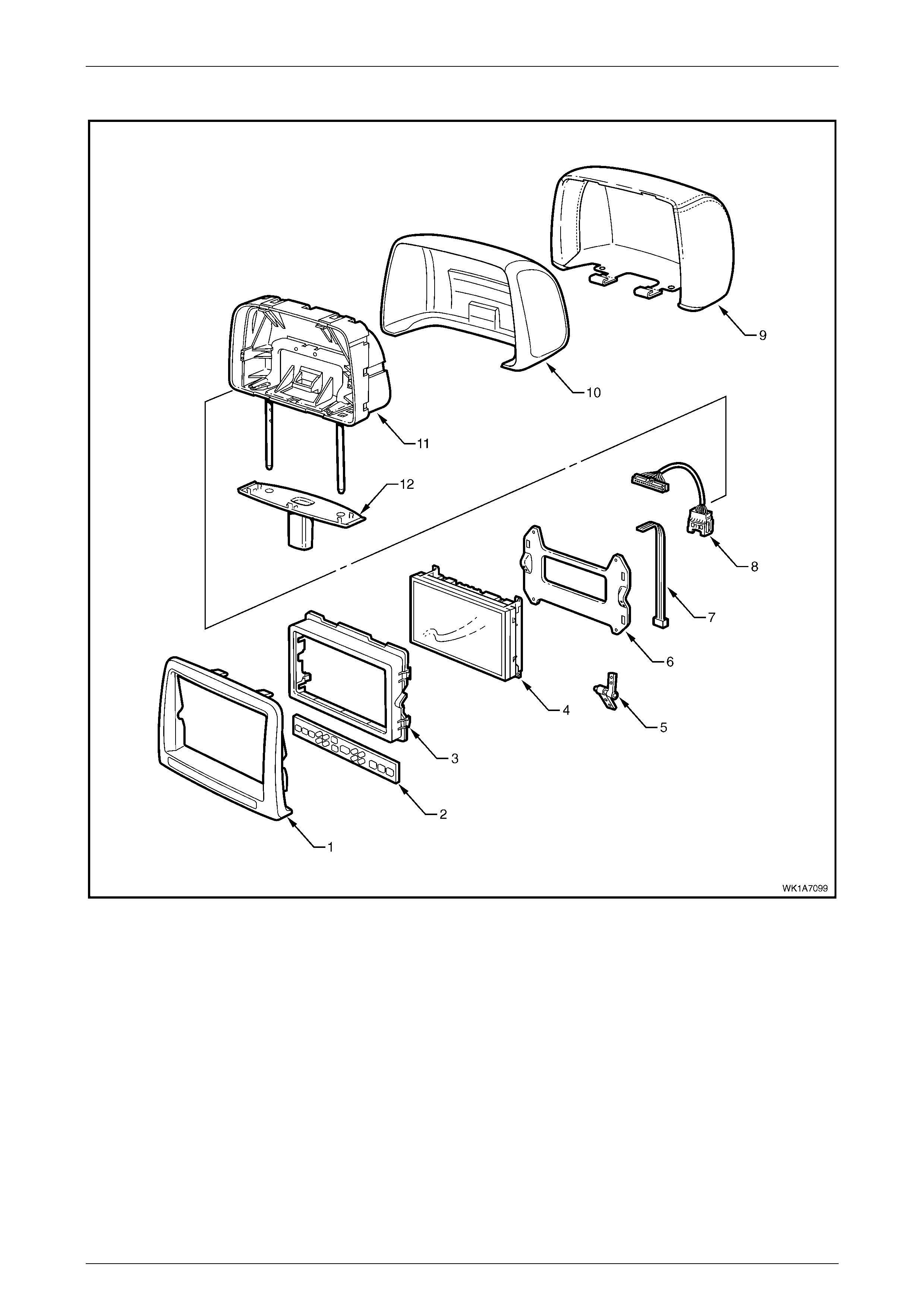
Seat Assemblies Page 1A7–129
Page 1A7–129
Front Seat Type 11 – 14 Head Restraint Assembly
Figure 1A7 – 88
Legend
1 Rear Seat Entert ainment Head Rest Esc utcheon Assembl y
2 Rear Seat Entert ainment Circuit Board
3 Rear Seat Entertainment Screen Bezel
4 Rear Seat Entert ainment Screen Assem bl y
5 Rear Seat Entert ainment Screen Pivot Hinge
6 Rear Seat Entert ainment Screen Mounting Pl at e
7 Rear Seat Entertainment Ribbon Harness
8 Rear Seat Entert ainment Upper Harnes s
9 Front Seat Head Restraint Cover
10 Front Seat Head Restraint Pad
11 Front Seat Head Restraint Frame
12 Front Seat Head Restraint Wiri ng Cover
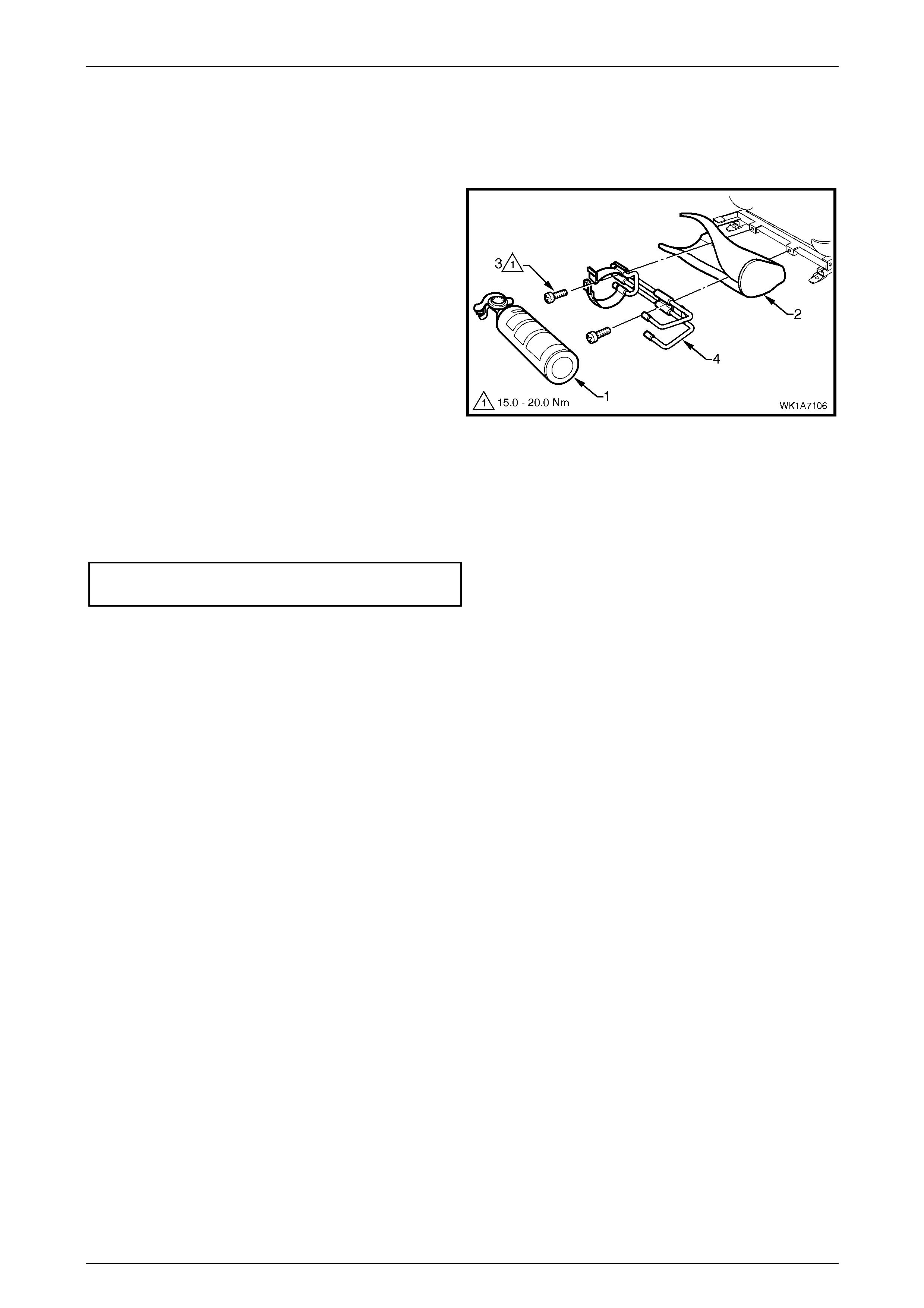
Seat Assemblies Page 1A7–130
Page 1A7–130
4.2 Fire Extinguisher Assembly
Remove
1 Remove the fire extinguisher (1) from the cover (2).
2 Remove the two screws (3) attaching the fire
extinguisher mounting bracket (4) to the track and
height adjust assembly.
3 Remove the bracket and cover from the track and
height adjust assembly. If required remove the bracket
from the cover.
Figure 1A7 – 89
Reinstall
Reinstallation of the fire extinguisher assembly is the reverse of the removal procedure, noting the following:
1 Tighten the attaching screws to the correct torque specification.
Fire extinguisher mounting bracket
attaching screw torque specific ation ....... 15.0 – 20.0 Nm
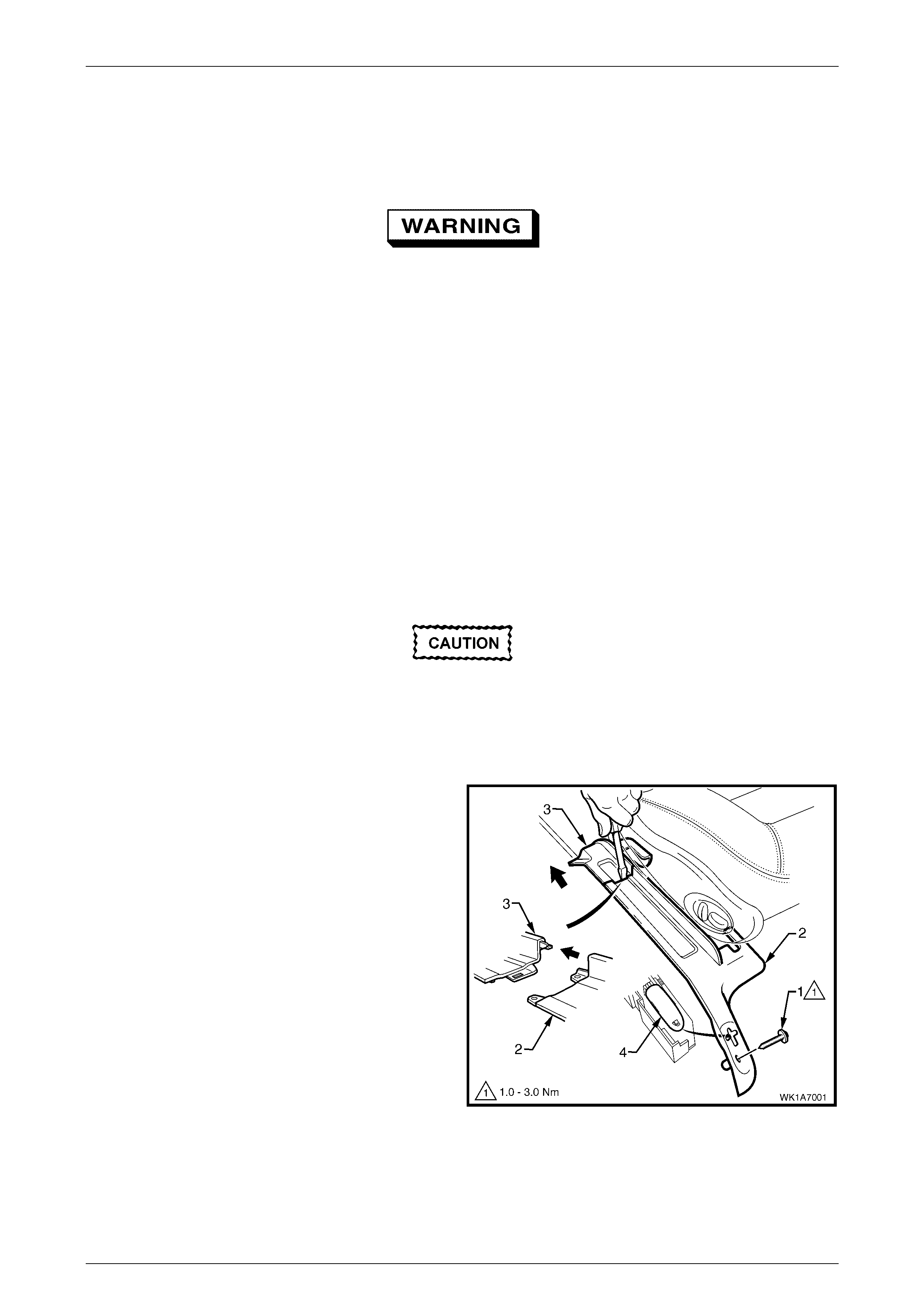
Seat Assemblies Page 1A7–131
Page 1A7–131
4.3 Front Seat Assembly
LT Section No. – 14-295
Before performing any service operation on a
front seat assembly fitted with side impact
airbags, ensure the occupant protection
system is disabled, refer to Section 12M
Occupant Protection System.
NOTE
If the seat assembly is to be disass embled, adjust
the seat assembly to its highest position before
disconnecting the power to the seat.
NOTE
Clean hands are essential when working on the
interior trim.
Remove
Disconnection of the battery affects certain
vehicle electronic systems. Refer to Section
00, 5 Battery Disconnection Procedures
before disconnecting the battery.
1 Disconnect the battery.
2 For the driver’s seat on right-hand drive vehicles,
remove the screw (1) attaching the front seat outer
front cover (2).
3 Using a small screwdriver, push in the centre of the
j
oin to separate the front cover and the front seat outer
lower rear cover (3).
4 Unclip the covers from the seat track and disengage
from the side sill trim.
5 Pull the covers apart and remove the rear cover.
6 For the driver’s seat on right-hand drive vehicles, slide
the front cover over the fuel filler door release lever (4)
and remove.
Figure 1A7 – 90
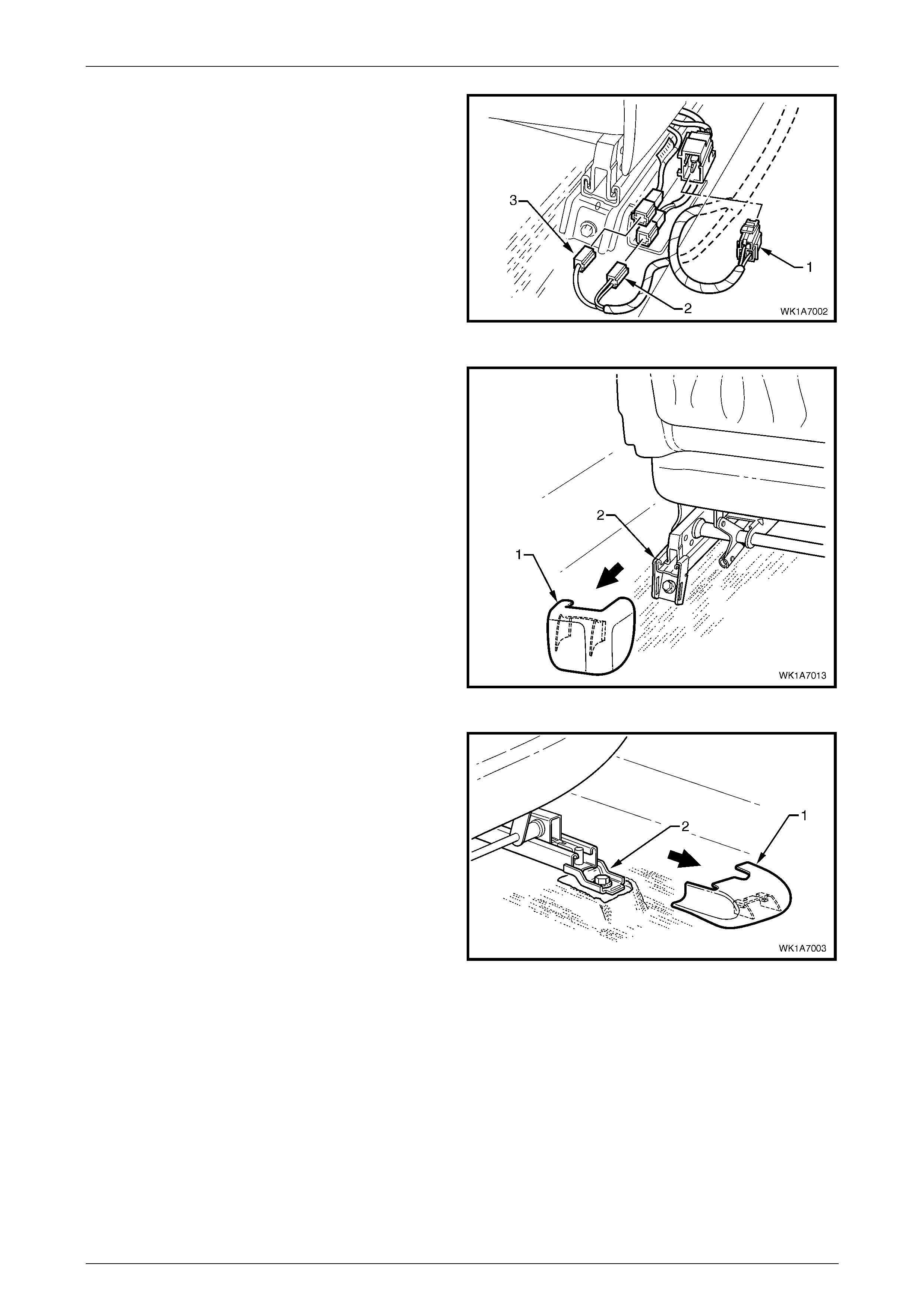
Seat Assemblies Page 1A7–132
Page 1A7–132
7 Disconnect the body wiring harness connector (1), the
seatbelt pretens ioner wiring co nnec tor (2) and the side
impact airbag w iring con nect or (3).
8 On vehicles fitted with Type 11 – 14 front seats,
disconnect the rear seat entertainment lower wiring
harness from the front of the seat track.
Figure 1A7 – 91
9 Unclip the front seat inner rear cover (1) from the seat
track (2).
Figure 1A7 – 92
10 Unclip the front seat inner front cover (1) from the seat
track (2).
Figure 1A7 – 93
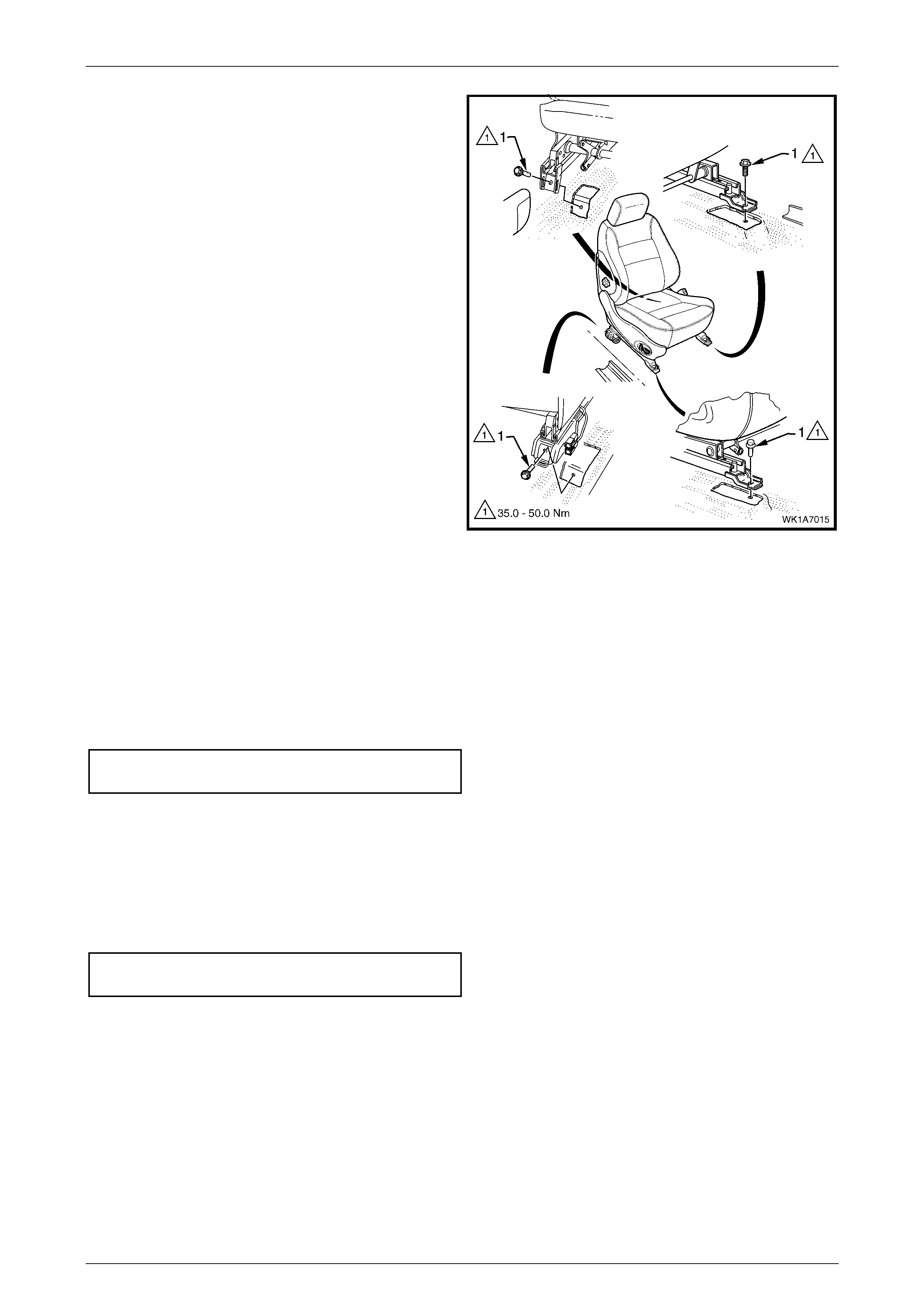
Seat Assemblies Page 1A7–133
Page 1A7–133
11 Remove the four screws (1) attaching the front seat to
the vehicle.
12 Remove the seat from the vehicle.
Figure 1A7 – 94
Reinstall
Reinstall atio n of the front seat ass emb ly is the reverse of the remov al proc edur e, noting the follow ing:
1 Position the front seat assembly into the vehicle.
2 Install the four screws securing the front seat.
3 Tighten the attaching screws to the correct torque specification.
Front seat assembly attac hing screw
torque specification ................................ 35.0 – 50.0 Nm
4 Connect the seat wiring harness connector, seatbelt pretensioner harness connector and the side impact airbag
connector.
5 Align the front seat outer cover’s retaining clips and push firmly to engage.
6 Push the front of the front seat outer cover down to engage the cover wi th the front of the seat rail.
7 For the driver’s side on right-hand drive vehicles, install the front seat outer cover attaching screw and tighten to the
specified torque.
Front seat outer front cover attaching
screw torque specification.......................... 1.0 – 3.0 Nm
8 Check the operation of the front seat functions. While checking the seat adjustment/operation, also check that the
seat wiring harnesses do not foul wi th any of the seat’s moveable components (i.e. seat motor drive shafts, etc.).
NOTE
Type 11 and 13 front seats will require seat
memory calibration to reinstate seat memory
functions, refer to Seat Memory Calibration, Front
Seat Type 11 and 13.

Seat Assemblies Page 1A7–134
Page 1A7–134
9 Switch the ignition on and observe the airbag warning indicator in the instrument cluster.
• If no fault is detected, the airbag warning indicator should illuminate for approximately five seconds while the
system performs a self-test, and then go off.
• If a fault is present, the airbag warning indicator will remain illuminated and a warning chime may sound after
approximately three seconds. The warning message ‘SRS Airbag Fault’ is also displayed in the instrument
cluster multi-function display. To diagnose the fault, refer to Section 12M, 4 Diagnostics.
Seat Memory Calibration, Front Seat Type 11 and 13
Whenever power is interrupted to the seat memory module, the following procedure must be performed to reinstate seat
memory functions.
Step Operation Result
1 1 Operate the seat adjustment switch to move the
seat forward.
2 Operate the seat adjustment switch for 1 second to
move the seat aft.
3 Operate the seat adjustment switch to move the
seat forward.
Seat will cease movement when track limit is
reached.
Seat will move aft.
Seat will cease movement when track limit is
reached.
2 1 Operate the seat adjustment switch to move the
seat aft.
2 Operate the seat adjustment switch for 1 second to
move the seat forward.
3 Operate the seat adjustment switch to move the
seat aft.
Seat will cease movement when track limit is
reached.
Seat will move forward.
Seat will cease movement when track limit is
reached.
3 1 Operate the seat adjustment switch to raise the
front of the seat.
2 Operate the adjustment switch for 1 second to
lower the front of the seat.
3 Operate the seat adjustment switch to raise the
front of the seat.
Seat will cease movement when upper limit is
reached.
Seat will lower.
Seat will cease movement when upper limit is
reached.
4 1 Operate the seat adjustm ent switch to lower the
front of the seat.
2 Operate seat adjustment switch for 1 second to
raise the front of the seat.
3 Operate the seat adjustment switch to lower the
front of the seat.
Seat will cease movement when lower limit is
reached.
Seat will raise.
Seat will cease movement when lower limit is
reached.
5 1 Operate the seat adjustment switch to raise the rear
of the seat.
2 Operate the seat adjustment switch for 1 second to
lower the rear of the seat.
3 Operate the seat adjustment switch to raise the rear
of the seat.
Seat will cease movement when upper limit is
reached.
Seat will lower.
Seat will cease movement when upper limit is
reached.
6 1 Operate the seat adjustm ent switch to lower the
rear of the seat.
2 Operate the seat adjustment switch for 1 second to
raise the rear of the seat.
3 Operate the seat adjustment switch to lower the
rear of the seat.
Seat will cease movement when lower limit is
reached.
Seat will raise.
Seat will cease movement when lower limit is
reached.

Seat Assemblies Page 1A7–135
Page 1A7–135
7 1 Operate the seat adjustment switch to move the
seat-back aft.
2 Operate the seat adjustment switch for 1 second to
move the seat-back forward.
3 Operate the seat adjustment switch to move the
seat-back aft.
Hold switch until lower limit is reached. This
does not have to be mechanical limit.
Seat-back will move forward.
Hold switch until lower limit is reached. This
should be same position as in 1.
8 1 Operate the seat adjustment switch to move the
seat-back forward.
2 Operate the seat adjustment switch for 1 second to
move the seat-back aft.
3 Operate the seat adjustment switch to move the
seat-back forward.
Hold switch until upper limit is reached. This
does not have to be mechanical limit.
Seat-back will move aft.
Hold switch until upper limit is reached. This
should be same position as in 1.
9 Press the mirror dip/memory store (M) button for 1
second. Stores the calibration into memory. A three-
tone chime sounds to confir m stora ge.
To test that the seat limits have been correctly calibrated, perform the following:
Step Operation Result
1 Operate the seat adjustment switch in one direction
(fore/aft, raise/lower, etc.). Hold until seat stops.
2 Release the switch briefly. –
3 Operate the switch in the same direction and hold for 3
seconds. The motor will not operate for 2 seconds, then
operates for 0.5 second.
This is a limp-home function that allows the
seat to be manually adjusted should a sensor
fail.

Seat Assemblies Page 1A7–136
Page 1A7–136
4.4 Front Seat Outer Side Cover Assembly
LT Section No. – 14-322
Remove
1 Raise the seat to the full-up position.
2 Remove the screw (1) from the front of the front seat
outer side cover (2).
3 If required, carefully prise the recliner knob (3) from
the seat assembly.
4 Remove the plug (4) by rotating the plug anti-
clockwise, one quarter of a turn.
4 Remove the screw (5) located behind the plug.
5 Reach up under the seat assembly and squeeze
together the two retaining tangs (6), on the inner side
of the side cover while gently pulling the cover.
6 Gently pull the side cover away from the seat to
disengage the two clips (7) attached to the seat-back
frame assembly .
NOTE
Only remove the side cover far enough away
from the seat cushion assembly to gain access
to the seat wiring harness connectors.
Figure 1A7 – 95
7 Disconnect the front seat adj u stme nt switch conne ctor
(1), recline motor harness connector (2) and where
fitted the memory position switch connector (3) and
unclip the harness from the side cover.
8 Remove the side cover.
Figure 1A7 – 96
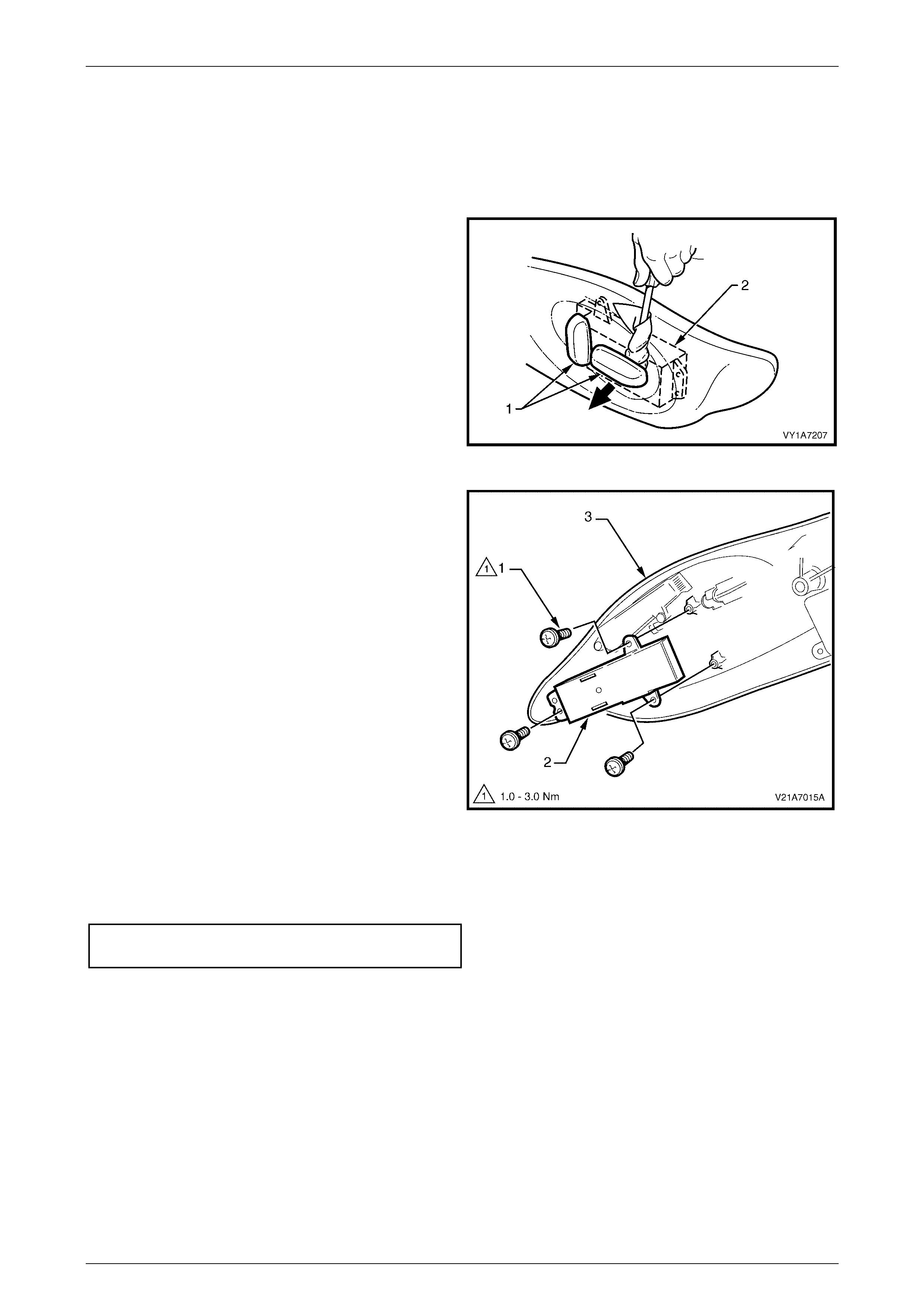
Seat Assemblies Page 1A7–137
Page 1A7–137
Disassemble
Front Seat A djustment Switch
Remove
1 Remove the two adjustment knobs (1) from the front
seat adjustment switch (2), by carefully prising them
free with a small flat tip screwdriver wrapped in a
clean shop rag.
Figure 1A7 – 97
2 Remove the three screws (1) attaching the front seat
adjustment switch (2) to the front seat outer side
cover (3).
3 Remove the adjustment switch.
Figure 1A7 – 98
Reinstall
1 Tighten the attaching screws to the correct torque specification.
Front seat adjust ment sw itch
attaching screw torque specific ation ........... 1.0 – 3.0 Nm
2 Push the knobs in until they click in place.
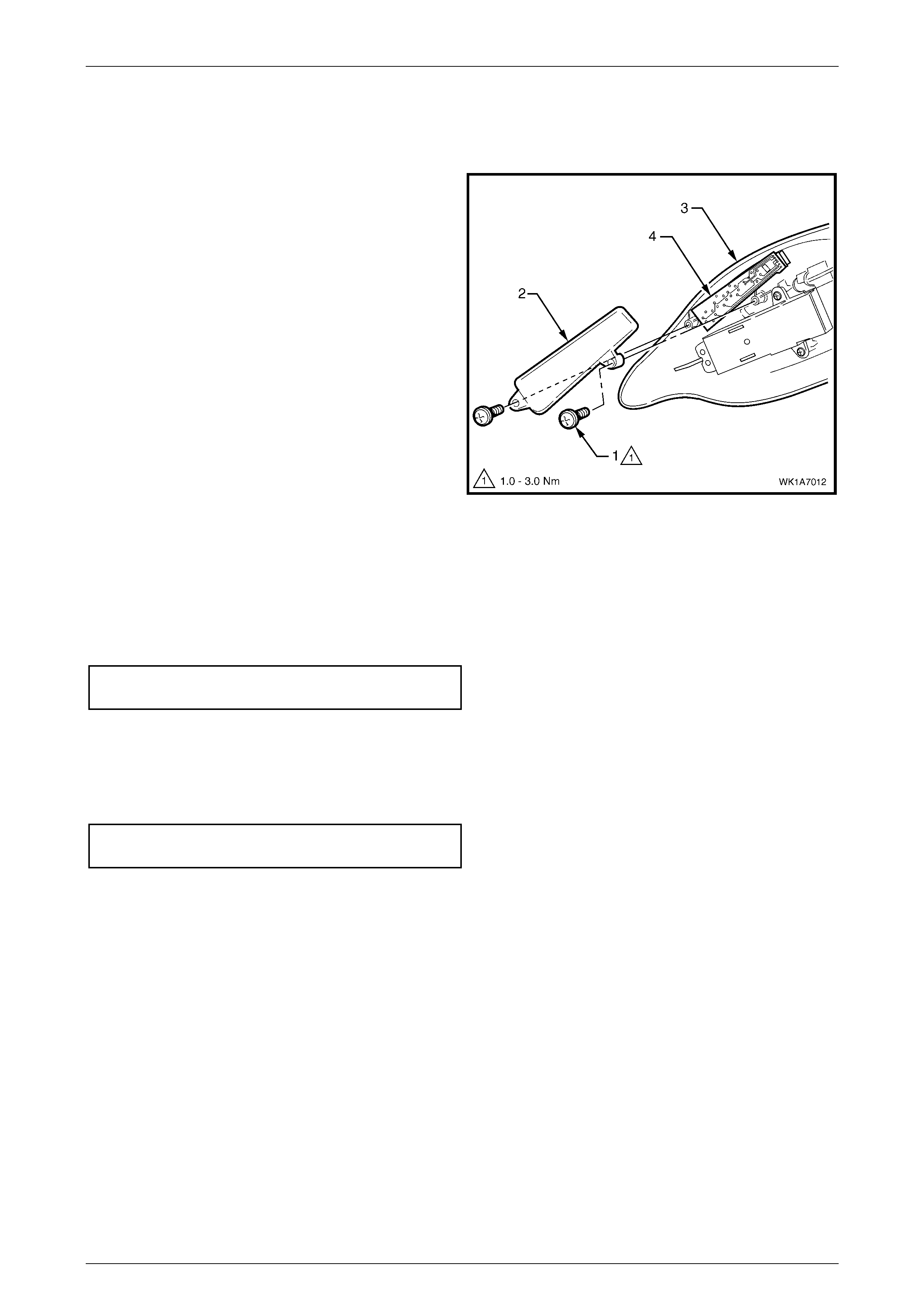
Seat Assemblies Page 1A7–138
Page 1A7–138
Memory Position Switch Assembly
Remove
1 Remove the screw (1) two places, attaching the
memory position switch cover (2) to the front seat
outer side cover (3).
2 Lift out the memory position switch assembly (4) from
its recess in the side cover.
3 As required, each position button can be removed
from the switch.
Figure 1A7 – 99
Reinstall
Reinstallation of the memory position switch assembly is the reverse of the removal procedure, noting the following:
1 If removed, push the position buttons in until they click in place, ensuring correct orientation.
2 Tighten the attaching screws to the correct torque specification.
Memory position switch cover
attaching screw torque specific ation ........... 1.0 – 3.0 Nm
Reinstall
Reinstallation of the front seat outer side cover is the reverse of the removal procedure, noting the following:
1 Tighten the attaching screws to the correct torque specification.
Front seat outer side cover att achi ng
screw torque specification.......................... 1.0 – 3.0 Nm
2 If fitted, ensure the recliner knob is securely clipped in place.
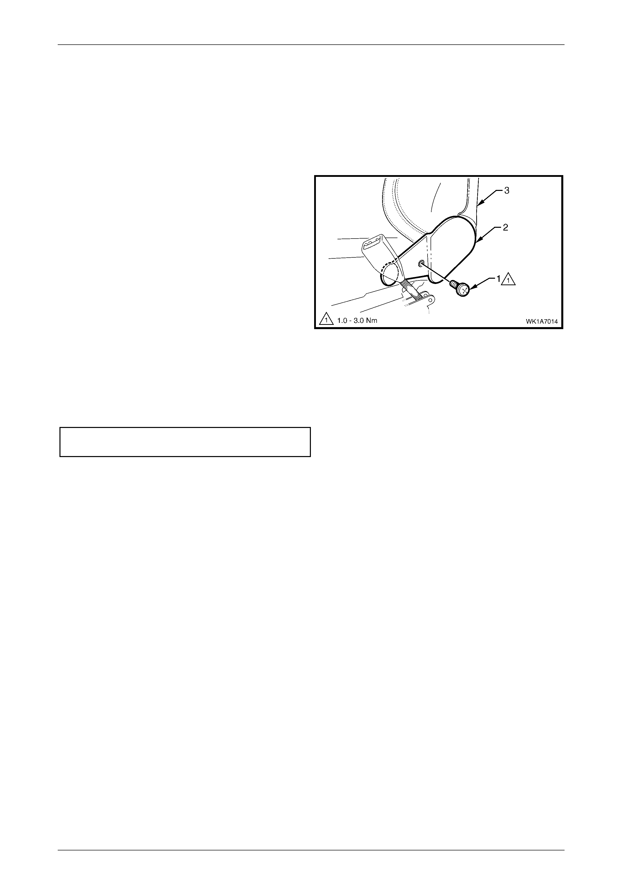
Seat Assemblies Page 1A7–139
Page 1A7–139
4.5 Front Seat Inner Side Cover
LT Section No. – 14-322
As required, remove the front seat assembly, refer to 4.3 Front Seat Assembly.
Remove
1 Remove the screw (1) attaching the front seat inner
side cover (2) to the seat assembly (3) and remove the
cover.
Figure 1A7 – 100
Reinstall
Reinstallation of the front seat inner side cover is the reverse of the removal procedure, noting the following:
1 Tighten the attaching screw to the correct torque specification.
Front seat inner side cover att achi ng
screw torque specification..........................1.0 – 3.0 Nm
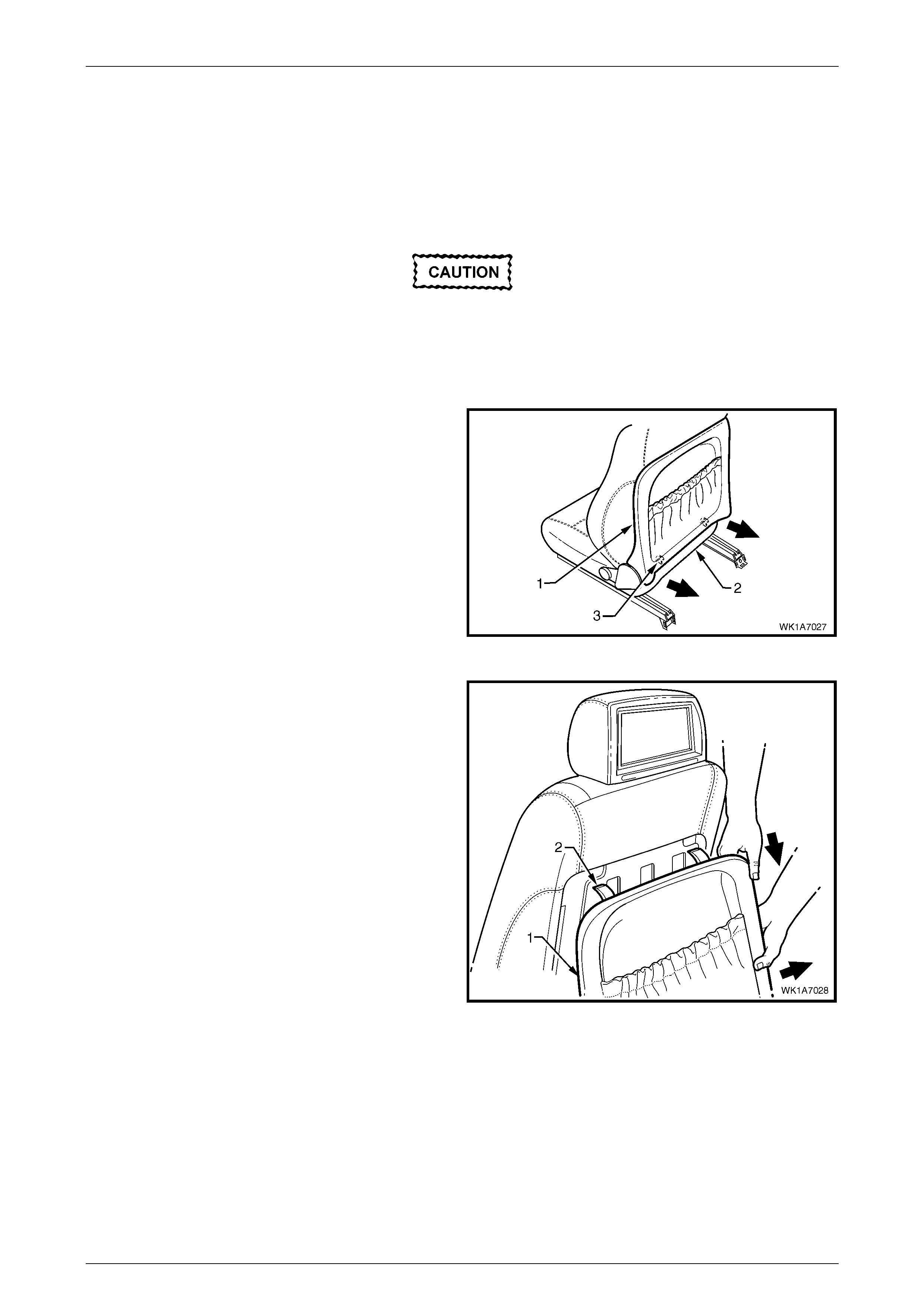
Seat Assemblies Page 1A7–140
Page 1A7–140
4.6 Front Seat-back Rear Co ver Assembly
LT Section No. – 14-322
Remove
The following component will require
replacement when performing this operation.
• Front seat back rear cover retaining clip,
two places.
1 Pull the lower corners of the front seat-back rear cover
(1) away from the seat (2), breaking the retaining clip
(3), two places.
Figure 1A7 – 101
2 While holding the lower portion of the front seat-back
rear cover (1) out, pull the cover down to release the
upper retaining lug (2), two places.
3 Remove the cover.
Figure 1A7 – 102
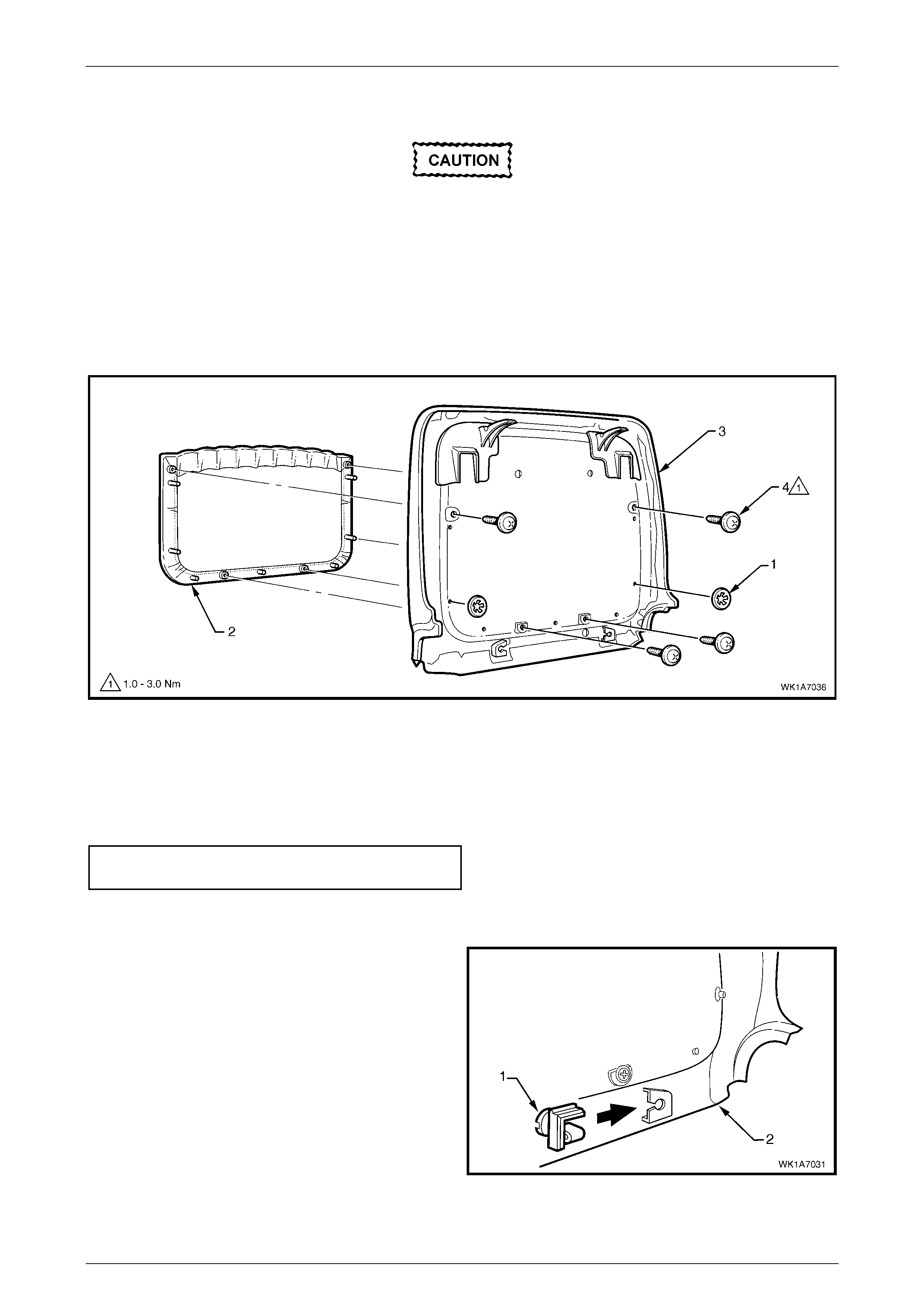
Seat Assemblies Page 1A7–141
Page 1A7–141
Disassemble
When performing Step 1, take care when
removing the retaining clip (1) not to break
the front seat-back map pocket shafts on
which the retaining clips are attached.
1 Remove the two retaining clips (1) attaching the front seat-back map pocket (2) to the front seat-back rear cove r
(3), refer to Figure 1A7 – 103.
2 Remove the four screws (4) attaching the map pocket to the cover.
3 Remove the map pocket.
Figure 1A7 – 103
Reassemble
Reassembly of the front seat-back rear cover is the reverse of the removal procedure, noting the following:
1 Tighten the attaching screws to the correct torque specification.
Front seat-bac k map pocket attaching
screw torque specification.......................... 1.0 – 3.0 Nm
Reinstall
1 Replace the damaged retaining clip (1) on the front
seat-back rear cover (2), two places .
Figure 1A7 – 104
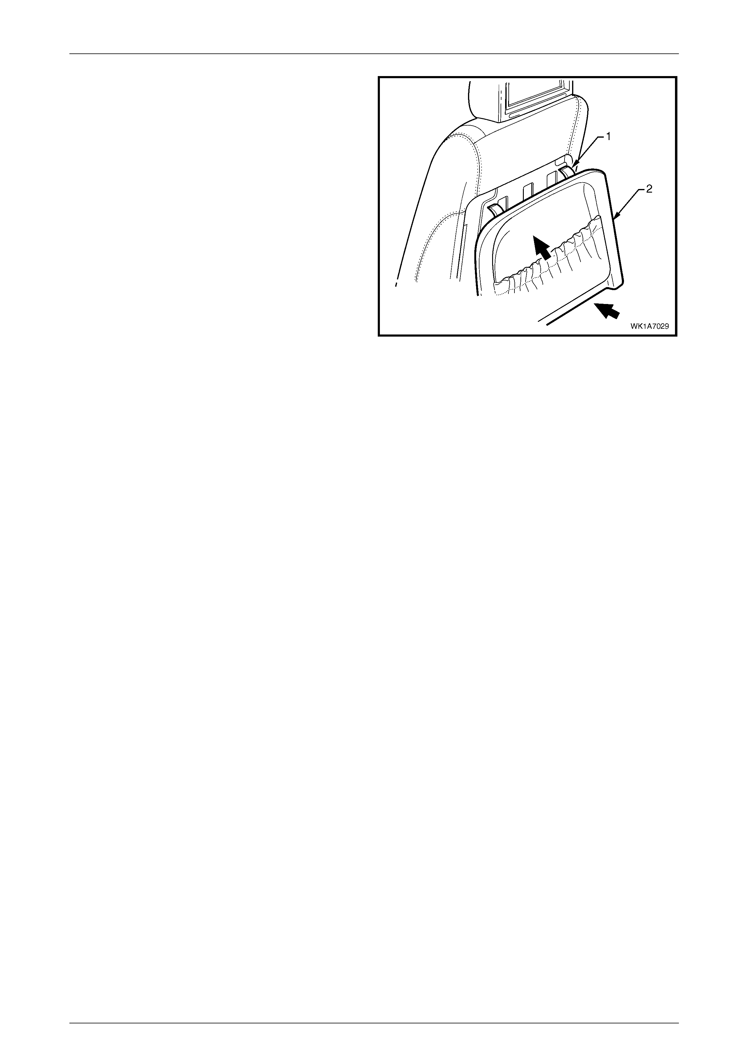
Seat Assemblies Page 1A7–142
Page 1A7–142
2 Locate the upper retaining lug (1), two places, with the
seat-back.
3 Push the front seat-back rear cover (2) up and in at
the lower edge to engage the two lower retaining clips.
Figure 1A7 – 105
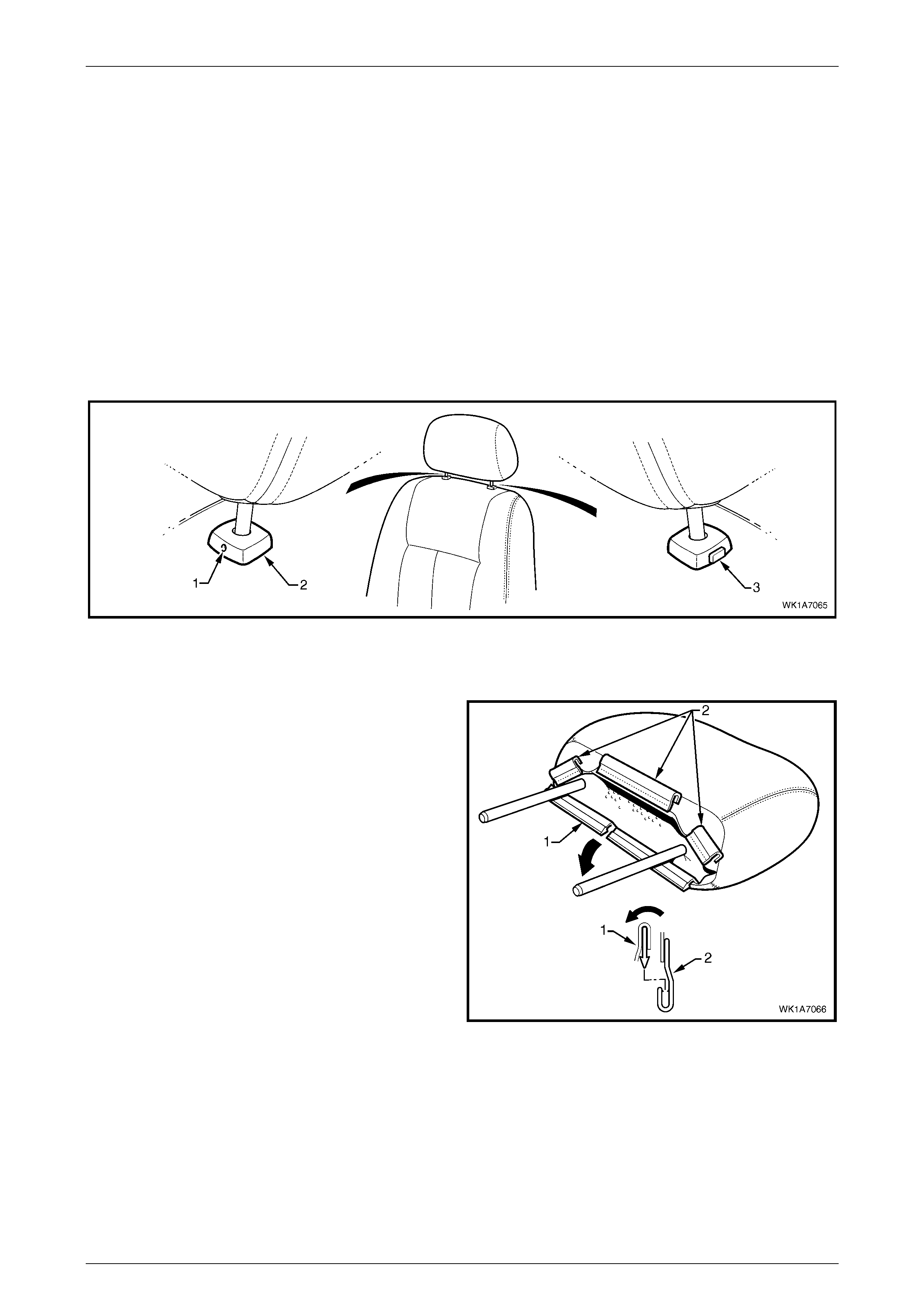
Seat Assemblies Page 1A7–143
Page 1A7–143
4.7 Front Seat Head Restraint Assembly
LT Section No. – 14-295
Front Seat Type 7 – 10
Remove
1 Raise the head restraint fully.
2 Insert a suitable size probe into the hole (1) in the right-hand head restraint sleeve (2), refer to Figure 1A7 – 106
3 Push the probe in slightly while applying slight upward pressure on the head restraint. Hold the upward pressure.
4 Depress the head restraint sleeve height adjuster lock (3) on the left-hand head restraint sleeve and remove the
head restraint.
Figure 1A7 – 106
Disassemble
1 Disengage the front head restraint cove r J-strip by
pulling the flaps (1) back and out of flaps (2) in the
direction shown.
2 Carefully remove the cover from the pad assembly
Figure 1A7 – 107
Reassemble
Reassembly of the front seat head restraint assembly is the reverse of the removal procedure, noting the following:
1 Ensure the head restraint cover J-clips are fully engaged.
Reinstall
Ensuring correct orientation of the head restraint, fit the head restraint shafts into the sleeves and push the head restraint
down.

Seat Assemblies Page 1A7–144
Page 1A7–144
Front Seat Type 11 – 14
Remove
1 Raise the head restraint fully.
2 Insert a suitable size probe into the hole (1) in the right-hand head restraint sleeve (2), refer to Figure 1A7 – 108
3 Push the probe in slightly while applying slight upward pressure on the head restraint. Hold the upward pressure.
4 Depress the head restraint sleeve height ad juster lock (3) on the left-hand head restraint sleeve and raise the he ad
restraint as high as possible without placing undue strain on the rear seat entertainment lower wiring harness (4).
Figure 1A7 – 108
5 Carefully prise the front of the front head restraint
wiring cover (1) from the head restraint to disengage
the two retaining clips (2), rotating the cover rearward.
6 Unattach the rear retaining lugs (3), six places and
lower the cover.
Figure 1A7 – 109
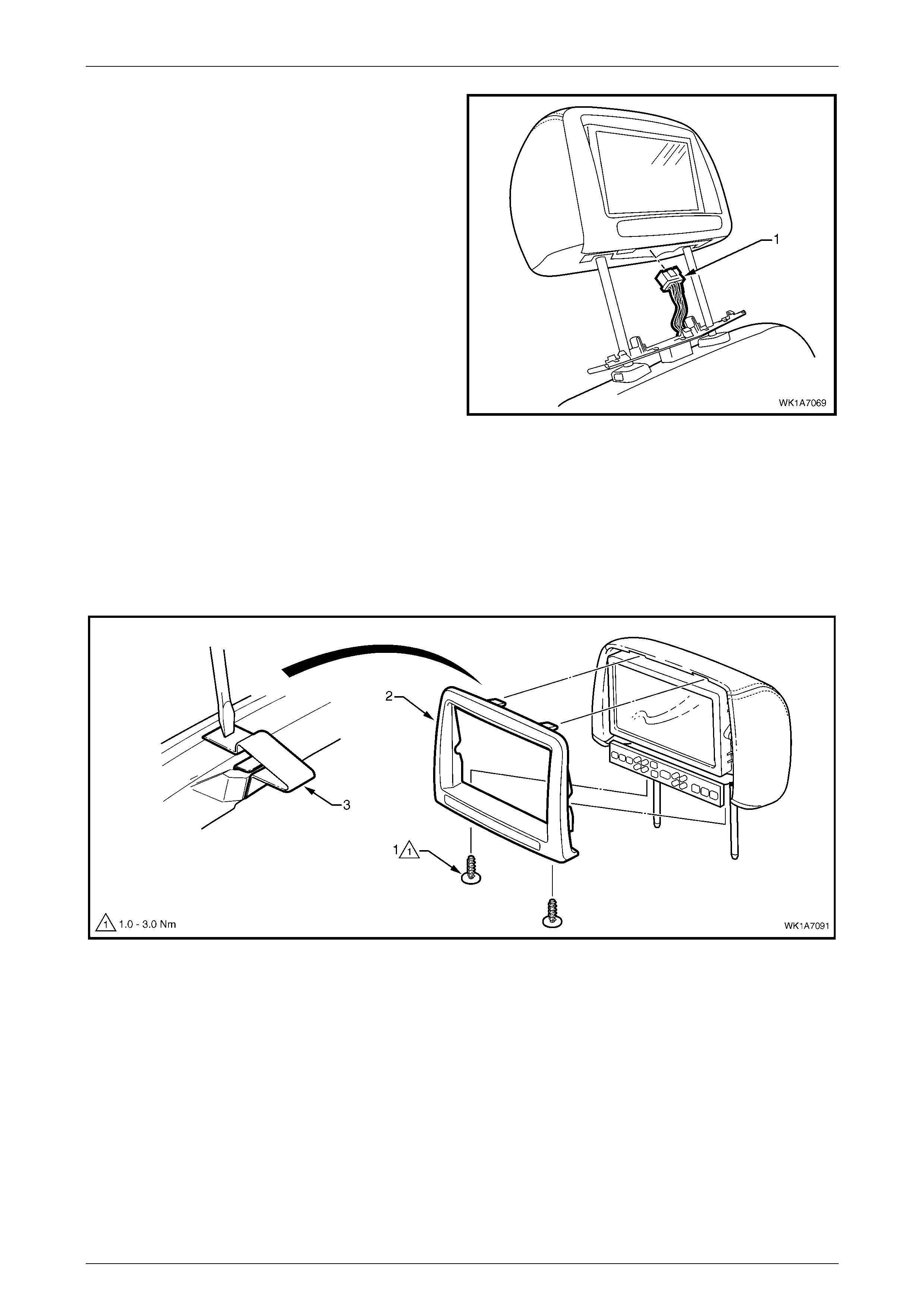
Seat Assemblies Page 1A7–145
Page 1A7–145
7 From below the head restraint, remove the rear seat
entertainment screen wiring connector (1) by
depressing its loc ki ng tab.
NOTE
A fine screwdriver may be needed to depress
the locking tab.
8 Remove the head restraint assembly and front head
restraint wiring c over.
Figure 1A7 – 110
Disassemble
1 Remove the two screws (1), attaching the rear seat entertainment head rest escutcheon (2) to the head restraint
assembly, refer to Figure 1A7 – 111.
2 Using a fine, flat-blade screwdriver carefully locate the retaining clip (3) along the upper edge. Depress the clip and
unattach the escut cheo n slig htly.
3 Repeat for the opposite retaining clip and remove the escutcheon.
Figure 1A7 – 111
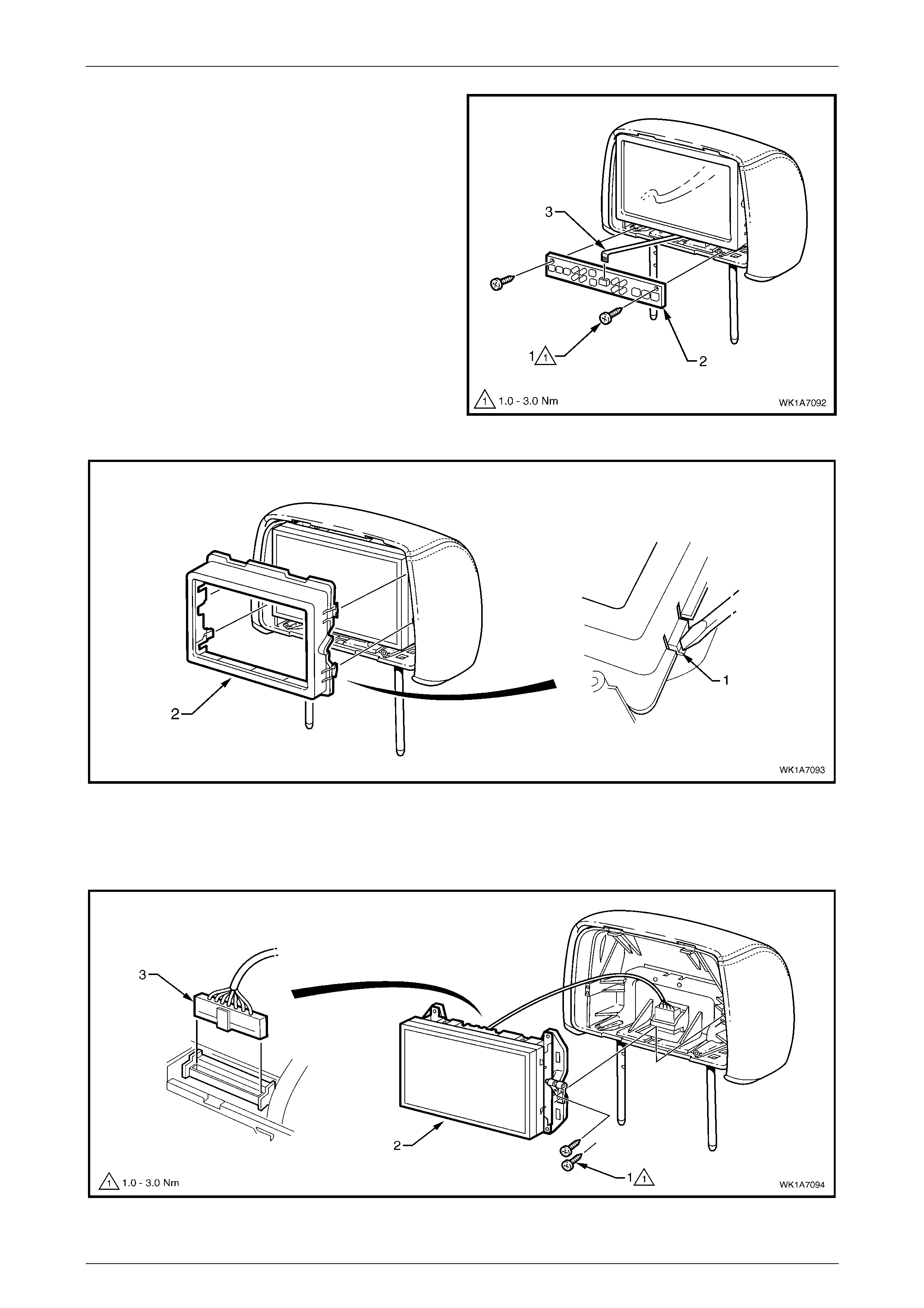
Seat Assemblies Page 1A7–146
Page 1A7–146
4 Remove the two screws (1), attaching the rear seat
entertainment circuit board (2) to the head restraint
assembly.
5 Disconnect the ribbon wiring (3) from the circuit board.
6 Depress the retaining lug (1), four places, and remove
the rear seat entertainment screen bezel (2), refer to
Figure 1A7 – 113.
Figure 1A7 – 112
Figure 1A7 – 113
7 Remove the two screws (1) each side, attaching the rear seat entertainment screen assembly (2) to the head
restraint assembly, refer to Figure 1A7 – 114.
8 Rotate the top of the screen assembly out and from behind carefully disconnect the wiring connector (3).
Figure 1A7 – 114
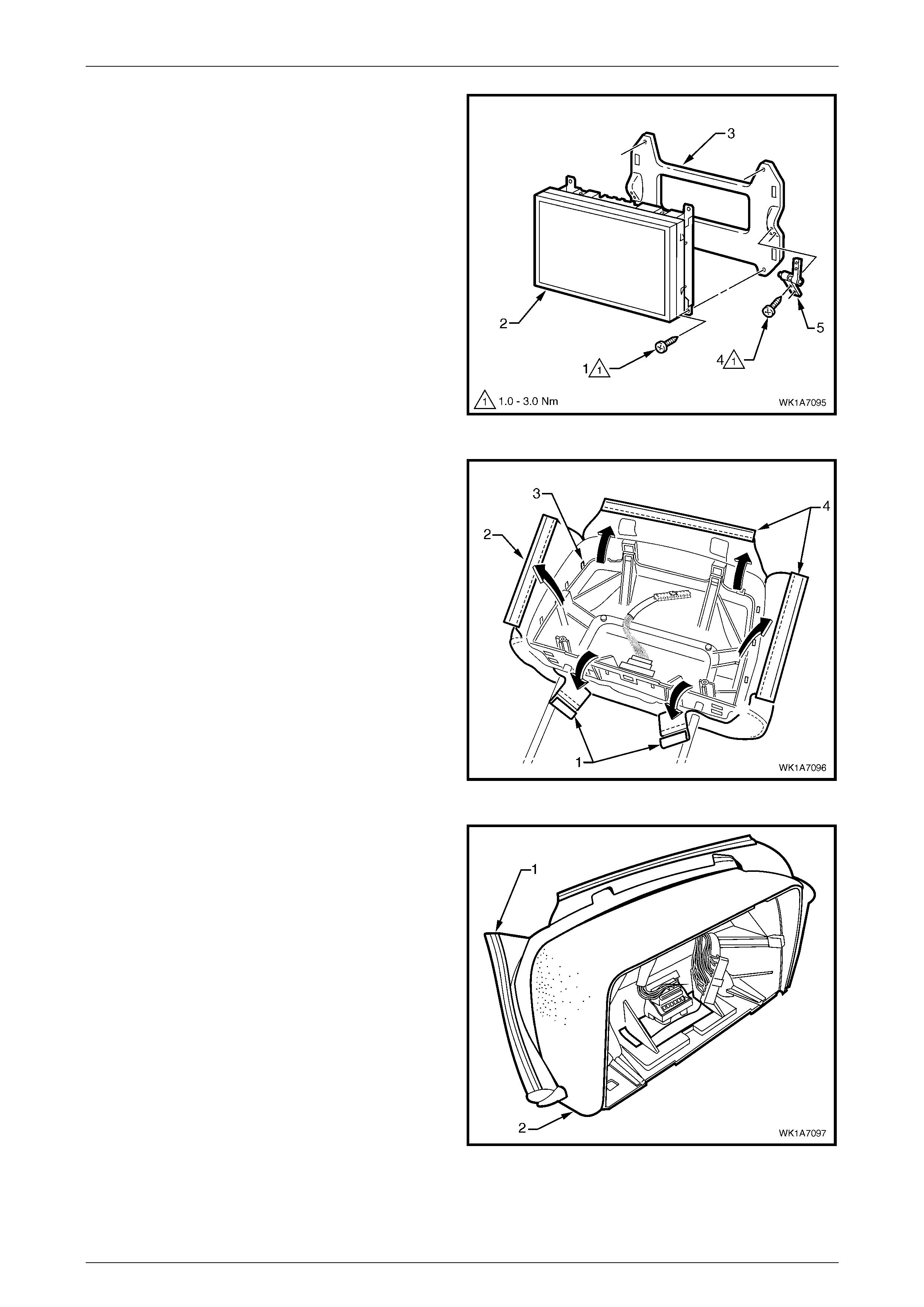
Seat Assemblies Page 1A7–147
Page 1A7–147
9 As required, remove the screw (1), four places,
attaching the rear seat entertainment screen (2) to the
mounting plate (3).
10 As required, remove the screw (4), two places,
attaching the pivot hinge (5) to the mounting plate.
11 Repeat for the opposite pivot hinge as required.
Figure 1A7 – 115
12 Disengage the two J-strips (1) attaching the head
restraint cover to the head restraint frame.
13 Using a fine, flat-blade screwdriver, prise the retaining
strip (2) from the locking tabs (3), three places, within
the head restraint frame recess.
14 Repeat for the two remaining strips (4).
Figure 1A7 – 116
15 Beginning at the upper corner, fold the head restraint
cover (1) from the head restraint pad (2).
16 Remove the cover (1) from the head restraint frame
(2), refer to Figure 1A7 – 118.
17 Remove the pad (3) from the frame.
Figure 1A7 – 117
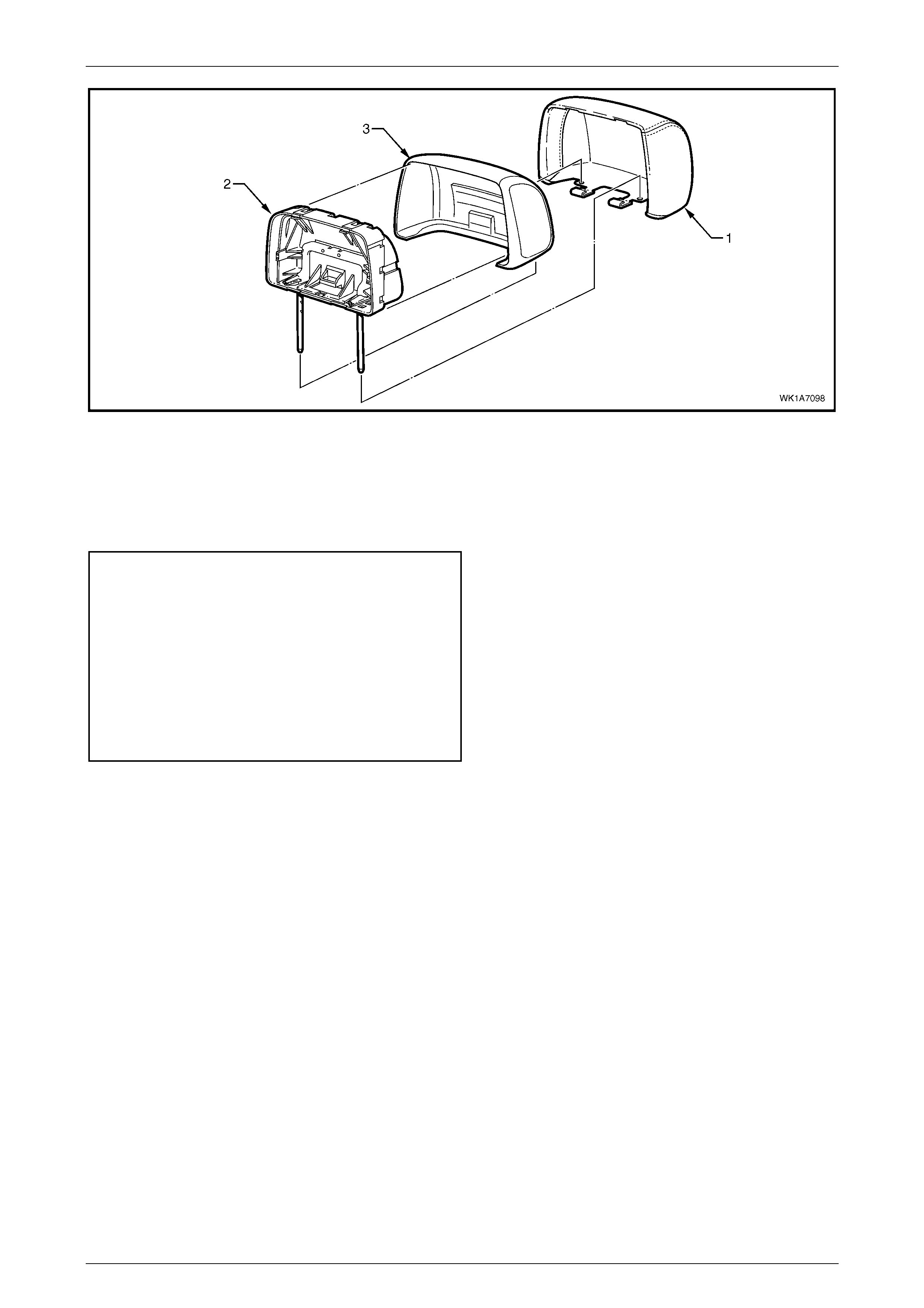
Seat Assemblies Page 1A7–148
Page 1A7–148
Figure 1A7 – 118
Reassemble
Reassembly of the front seat head restraint assembly is the reverse of the disassembly procedure, noting the following:
1 Tighten the sc rews to the specified torque.
Rear seat entertainment screen pivot
hinge attaching screw torque
specification................................................1.0 – 3.0 Nm
Rear seat entertainment screen
attaching screw torque specific ation ........... 1.0 – 3.0 Nm
Rear seat entertainment circuit board
attaching screw torque specific ation ........... 1.0 – 3.0 Nm
Rear seat entertainment head rest
escutcheon attaching screw torque
specification................................................1.0 – 3.0 Nm
Reinstall
Reinstallation of the front seat head restraint assembly is the reverse of the removal procedure noting the following:
1 Seat the front head restraint wiring cover in position on the seat-back, feeding the rear seat entertainment lower
wiring harness through the cavity and en suring the cover is correctly orientated.
2 Sit the head restraint assembly in position in the head restraint sleeves, connect the wiring harness and clip the
wiring cover in place.
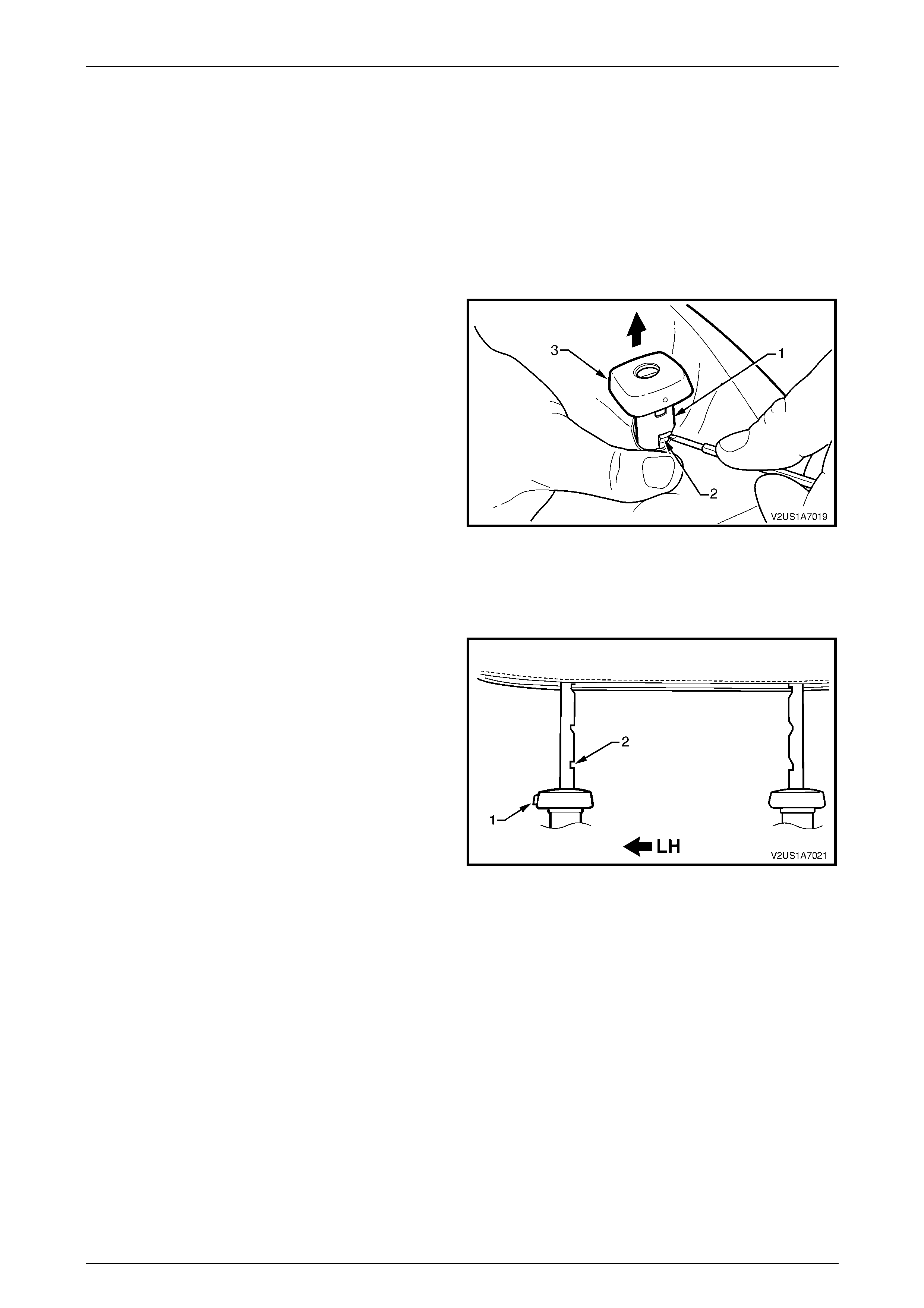
Seat Assemblies Page 1A7–149
Page 1A7–149
4.8 Front Seat Head Restraint Sleeve
As required, remove the front seat head restraint assembly, refer to 4.7 Front Seat Head Restraint Assembly.
LT Section No. – 14-275
Front Seat Type 7 – 10
Remove
1 Push down on the surrounding seat cover to reveal the
upper portion of the seat-back frame or active head
restraint frame (1).
2 Using a fine flat-blade screwdriver, depress the head
restraint sleeve retaining lug (2) and withdraw the
head restraint sleeve (3) from the frame.
3 Repeat for the remaining sleeve as required.
Figure 1A7 – 119
Reinstall
Reinstallation of the front seat head restraint sleeve is the reverse of the removal procedure, noting the following:
NOTE
Ensure the sleeve with the height adjuster lock
(1) is installed on the left-hand side of the seat;
that is the side that corresponds to the lower
square notch (2) in the head restraint shaft.
Figure 1A7 – 120
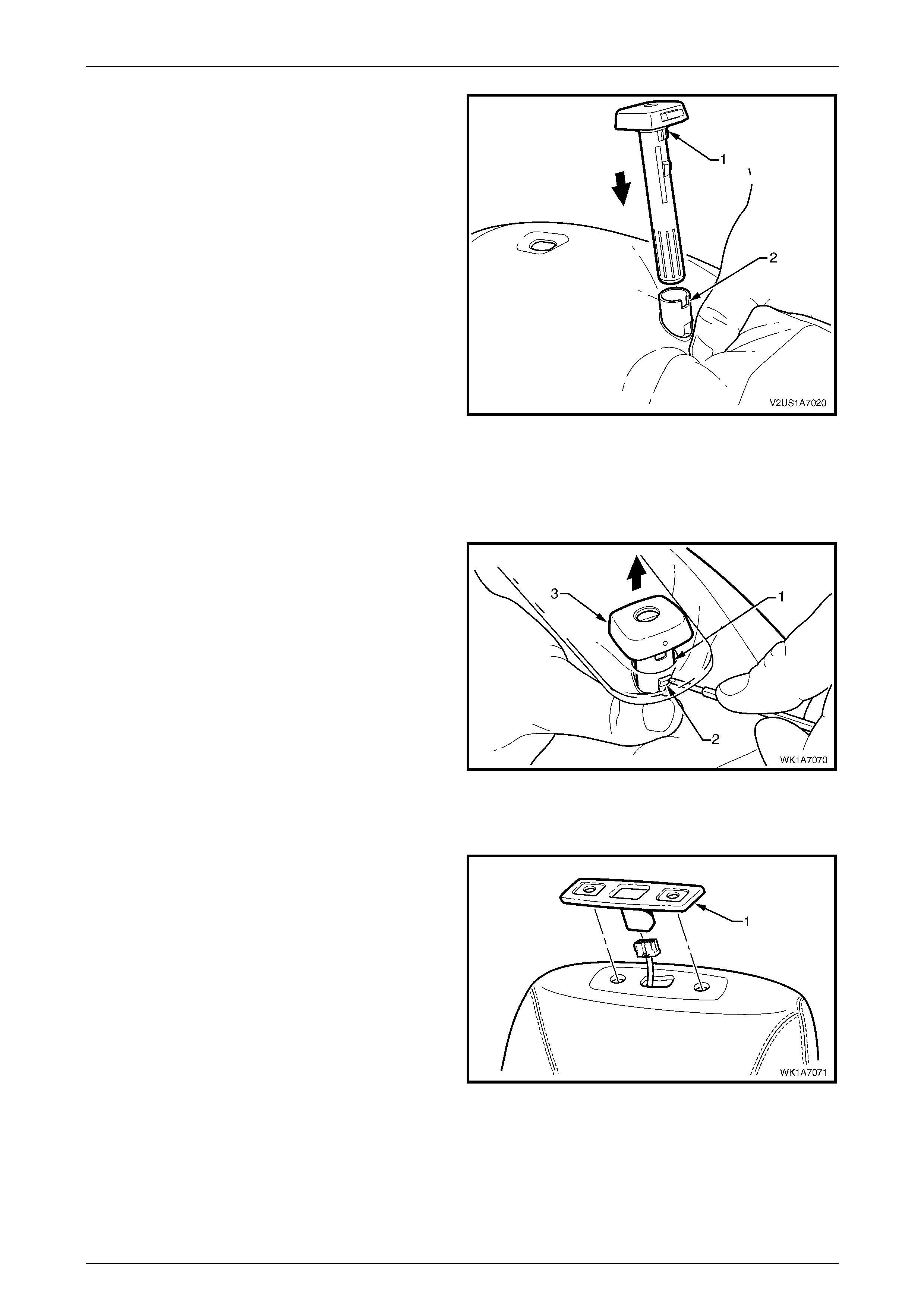
Seat Assemblies Page 1A7–150
Page 1A7–150
1 Align the head restraint sleeve locating ribs (1) with
the notch (2) in the seat-back frame.
2 Insert the sleeve and ensure it clicks into place.
Figure 1A7 – 121
Front Seat Type 11 – 14
Remove
1 Push down on the surrounding seat cover to reveal the
upper portion of the active head restraint frame (1)
below the front seat head restraint guide cover.
NOTE
If the front seat-back rear cover has been
removed, have an assistant pull on the active
head restraint strap to raise the sleeves.
Do not remove the rear cover unless necessary
as the retaining clips will break requiring
replacement, refer to 4.6 Front Seat-back Rear
Cover Assembly.
2 Using a fine flat-blade screwdriver, depress the head
restraint sleeve retaining lug (2) and withdraw the
head restraint sleeve (3) from the frame.
3 Repeat for the remaining sleeve as required.
Figure 1A7 – 122
4 Lift off the front seat head restraint guide cover (1).
Figure 1A7 – 123
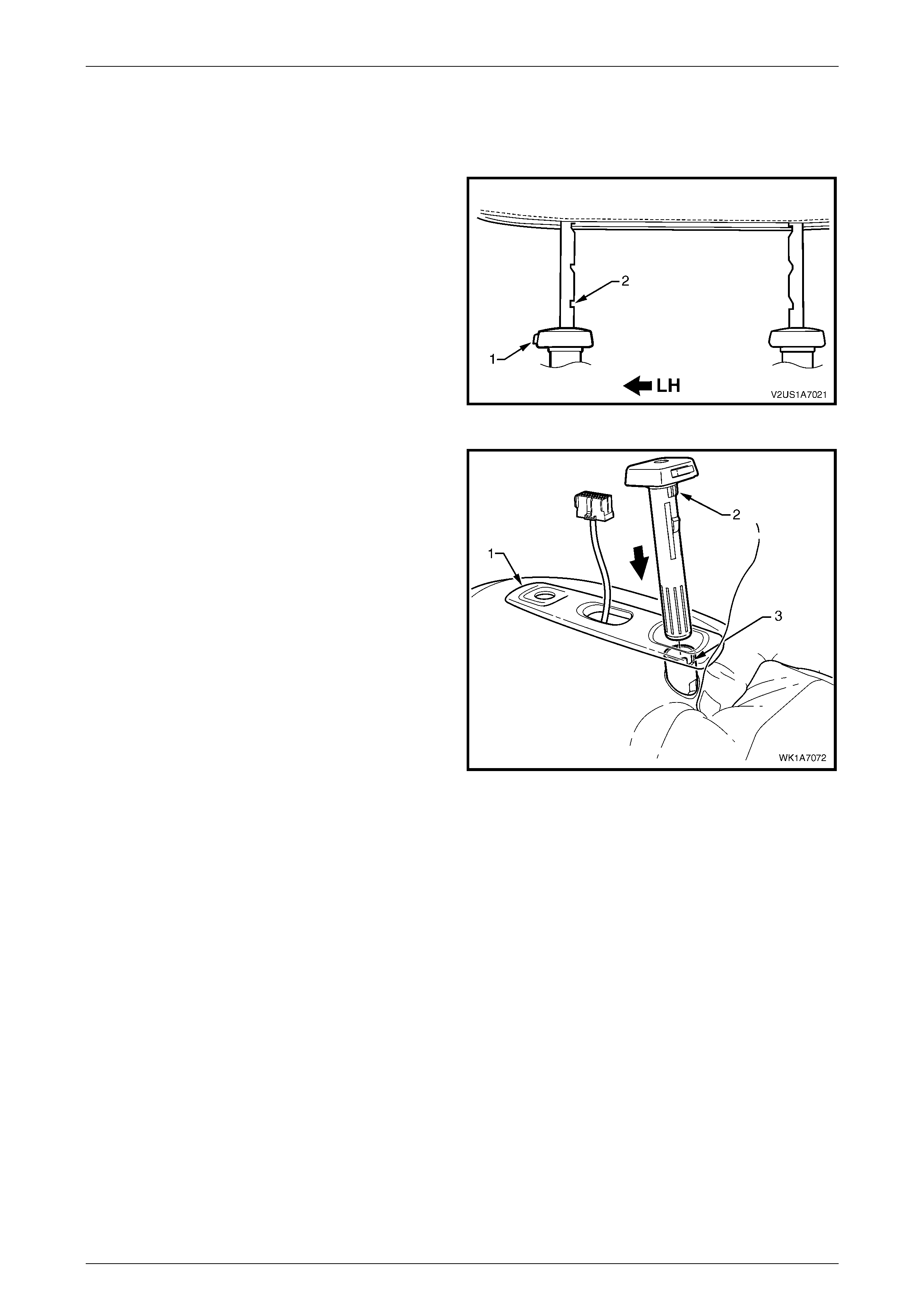
Seat Assemblies Page 1A7–151
Page 1A7–151
Reinstall
Reinstallation of the front seat head restraint sleeve is the
reverse of the removal procedure, noting the following:
NOTE
Ensure the sleeve with the height adjuster lock
(1) is installed on the left-hand side of the seat;
that is the side that corresponds to the lower
square notch (2) in the head restraint shaft.
Figure 1A7 – 124
1 Feed the rear seat entertainment lower wiring harness
assembly through the front seat head restraint guide
cover (1) and fit the cover in position.
2 Align the head restraint sleeve locating ribs (2) with
the notch (3) in the seat-back frame.
3 Insert the sleeve and ensure it clicks into place.
Figure 1A7 – 125
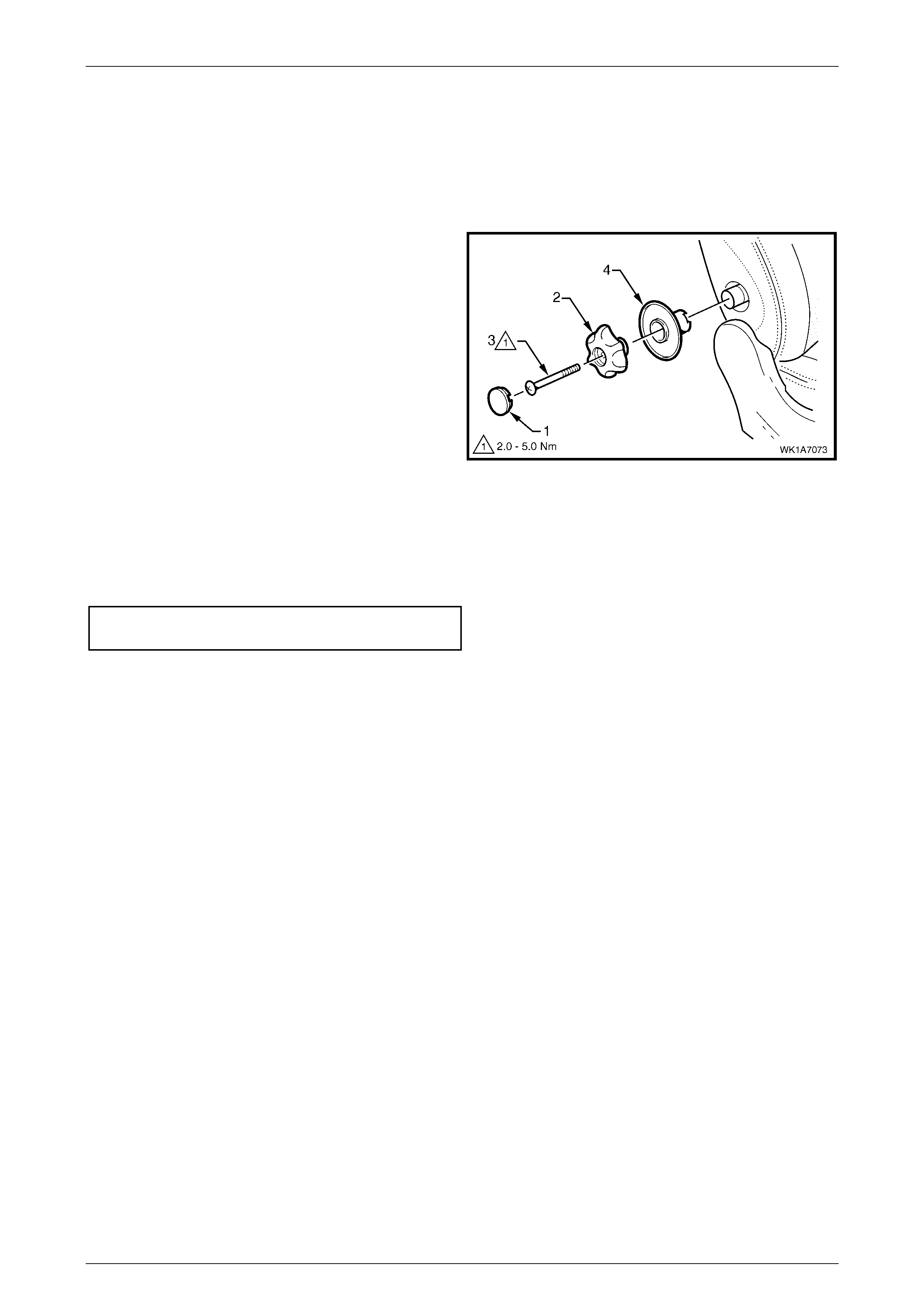
Seat Assemblies Page 1A7–152
Page 1A7–152
4.9 Lumbar Support Knob Assembly
LT Section No. – 14-275
Remove
1 Using a fine flat-blade screw-driver, carefully prise the
cap (1) from the lumbar support knob (2).
2 Remove the screw (3) attaching the knob to the
lumbar support shaft.
3 Pull the knob off the lumbar support shaft and remove
the lumbar support deflector ring (4).
NOTE
The knob is lightly clipped to the lumbar support
shaft and will ‘click-off’.
Figure 1A7 – 126
Reinstall
Reinstallation of the lumbar support knob assembly is the reverse of the removal procedure, noting the following:
1 Tighten the screw to the correc t torque specification.
Lumbar support knob attaching
screw torque specification.......................... 2.0 – 5.0 Nm
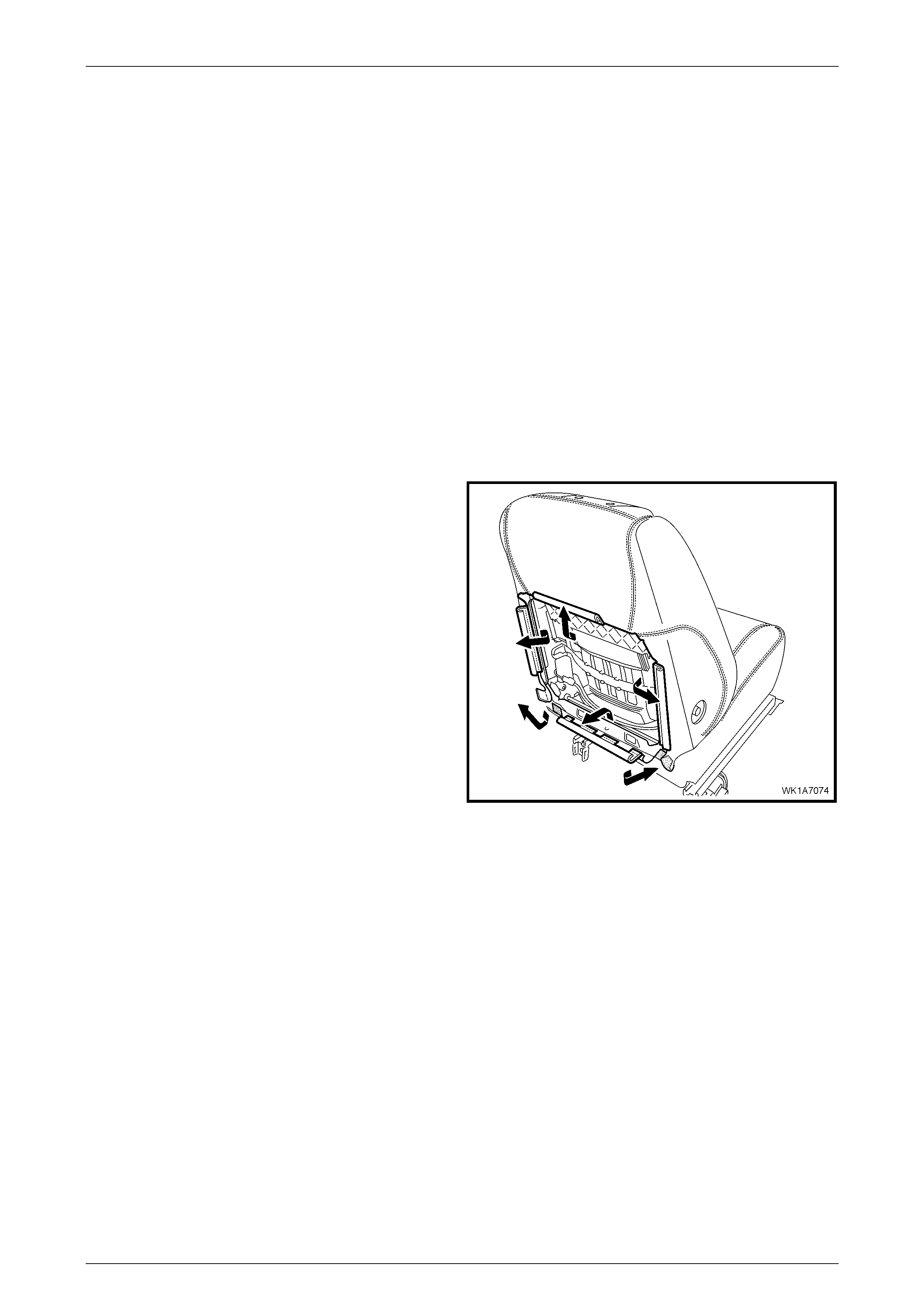
Seat Assemblies Page 1A7–153
Page 1A7–153
4.10 Front Seat-back Pad and Cover
Assembly
LT Section No. – 14-295
As required, remove the following components:
1 Front seat assembly, refer to 4.3 Front Seat Assemb ly.
2 Front seat outer side cover, refer to 4.4 Fron t Seat Outer Side C over A ssemb ly.
3 Front seat inner side cover, refer to 4.5 Front Seat Inner Side Cover.
4 Front seat-back rear cover assembly, refer to 4.6 Front Seat-back Rear Cover Assembly.
5 Front seat head restraint assembly, refer to 4.7 Front Seat Head Restraint Assembly.
6 Front seat head restraint sleev es, refer to 4.8 Front Seat Head Restraint Sleeve.
7 Lumbar support knob assembly, refer to 4.9 Lumbar Support Knob Assembly.
Remove
1 Disengage the J-strips from the seat fram e and the
Velcro tab at each lower corner.
2 Lift the cover and pad assembly up and away from the
seat-back frame, manoeuvring it over the seat-back
components such as the side impact airbag and
dummy block insert assemblies.
Figure 1A7 – 127
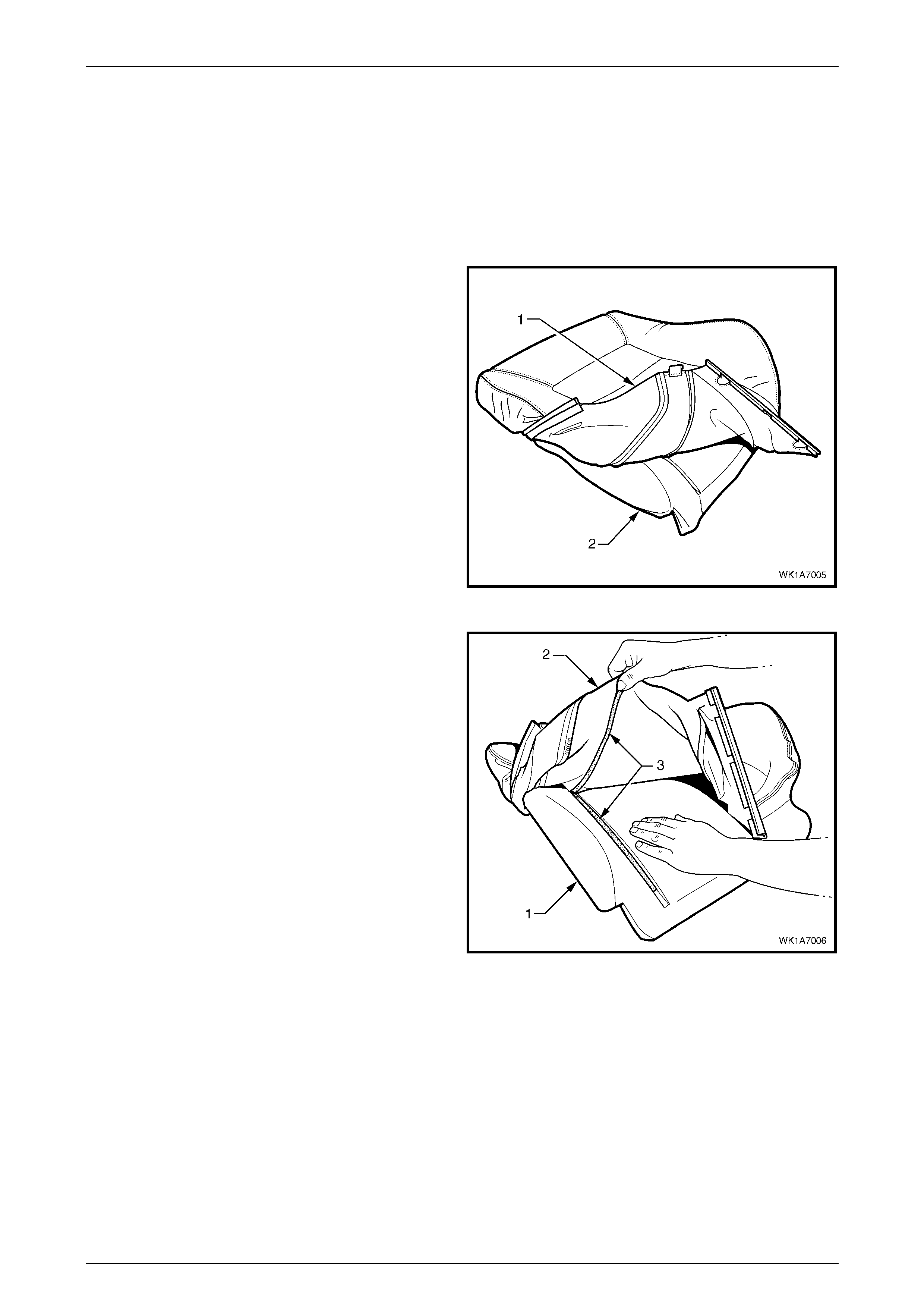
Seat Assemblies Page 1A7–154
Page 1A7–154
Disassemble
NOTE
The following illustrations show typical hook and
loop arrangement, which will vary according to
seat type.
Surebond type seat-back cover and pad
assemblies cannot be disassembled.
1 Fold the lower corners of the seat-back cover (1) over
the seat-back pad (2).
Figure 1A7 – 128
2 While holding the front seat-back pad (1), pull the
lower corners of the seat-back cover (2), upwards and
away from the front seat pad to disengage the hook
and loop strips (3).
3 Pull the front seat-back cover up and over the upper
edge of the front seat-back pad.
Figure 1A7 – 129
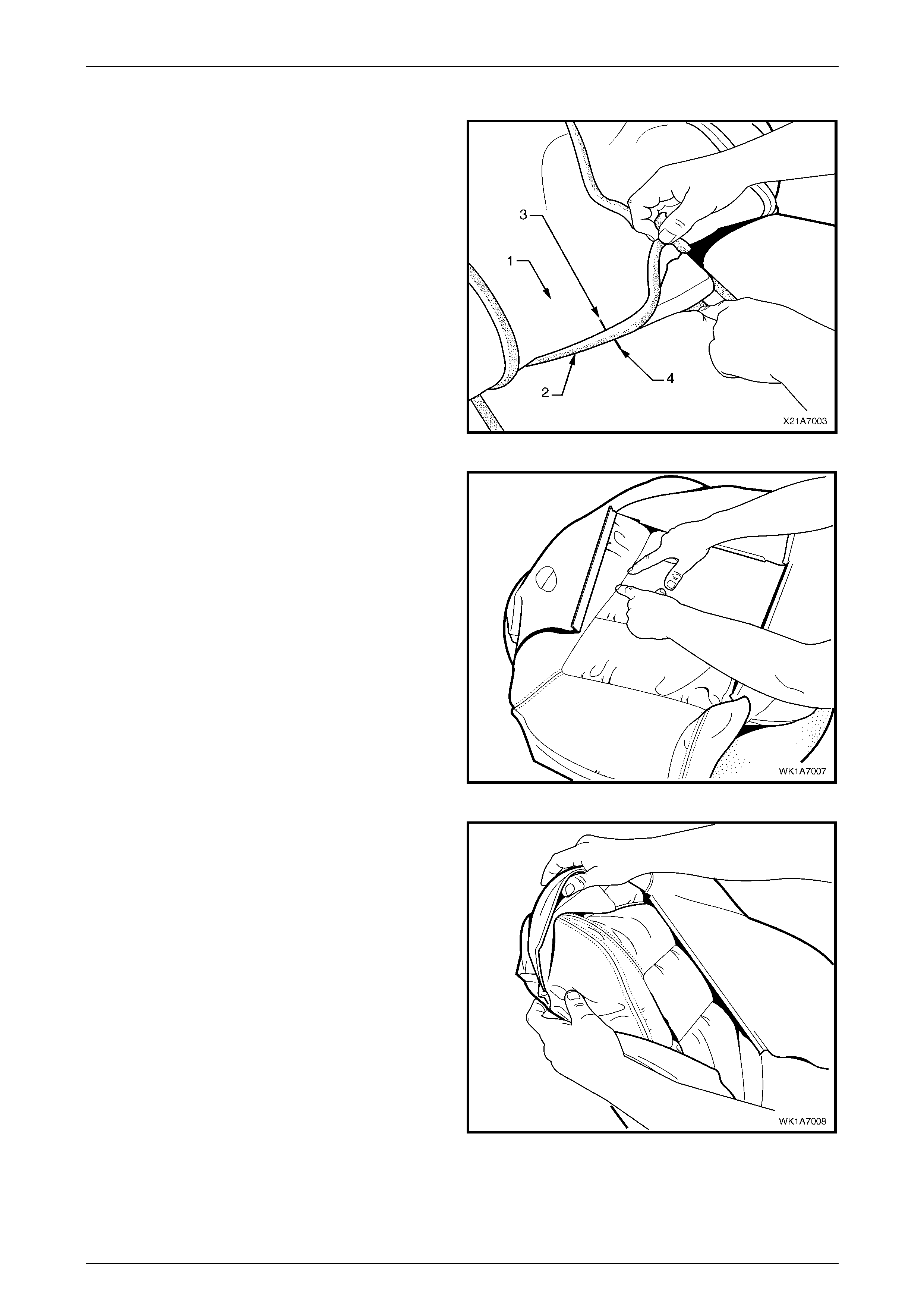
Seat Assemblies Page 1A7–155
Page 1A7–155
Reassemble
1 With the seat-back cover (1) folded at the central
horizontal strip of hook and loop (2), align the centre
mark (3) on the front s eat-back cover with the centre
mark (4) on the seat-back pad.
2 Press the seat-ba ck cov er fir m ly into the
corresponding groove in the seat-ba ck pad to enga ge
the hook and loop.
Figure 1A7 – 130
3 With the seat cover folded at the two vertical strips of
the hook and loop, press the seat-back cover firmly
into the correspo ndin g groov e s in the seat-ba ck pad.
Figure 1A7 – 131
4 Roll the upper corners of the front seat-back cover
over the seat-back pad.
5 Roll the sides of the seat-back cover over the seat-
back pad.
6 Roll the lower corners of the seat-back cover over the
seat-back pad.
NOTE
Make sure the cover is fitted neatly by hand into
all corners and contours of the seat pad.
Figure 1A7 – 132
Reinstall
Reinstallation of the front seat-back pad and cover assembly is the reverse of the removal procedure.
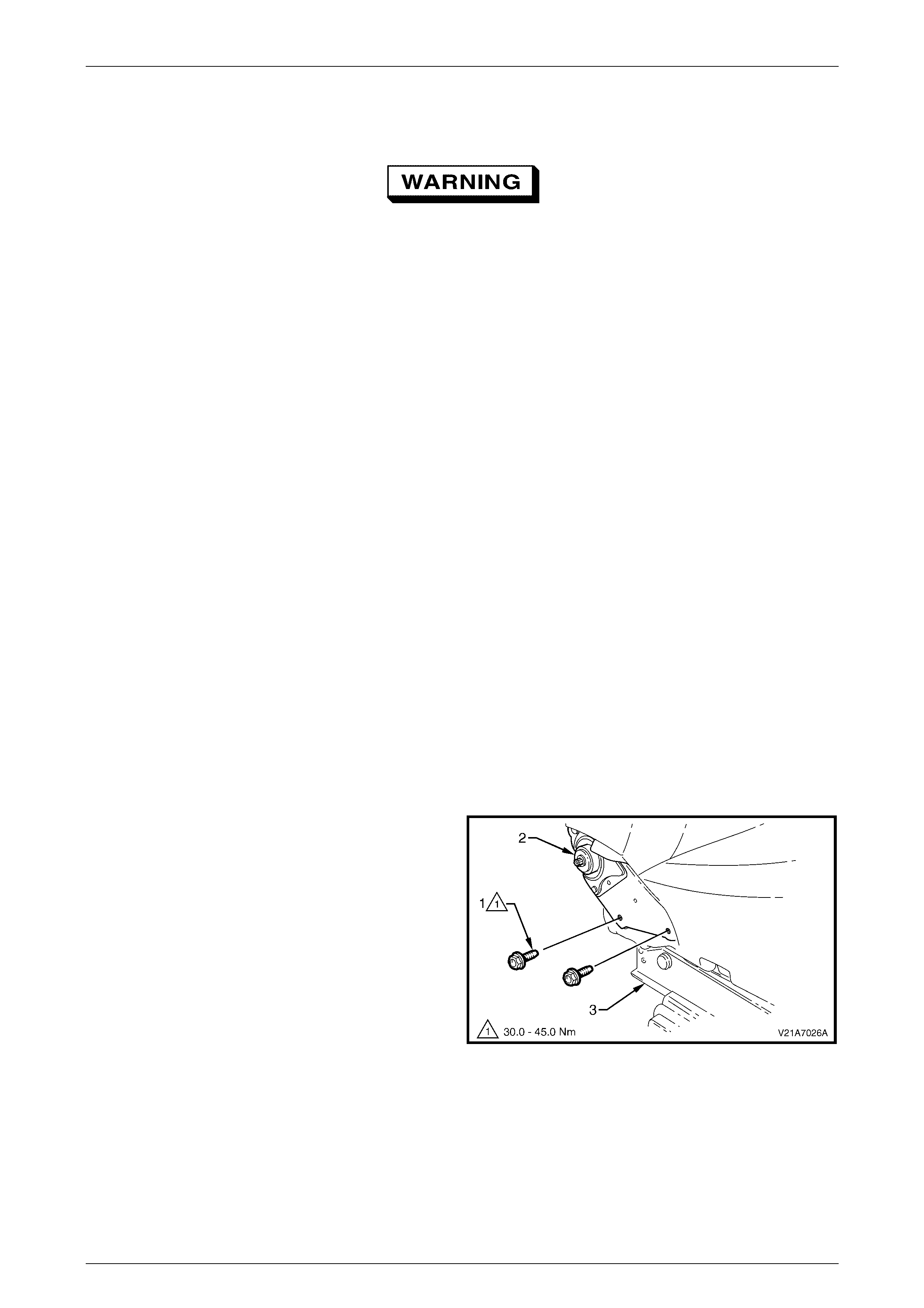
Seat Assemblies Page 1A7–156
Page 1A7–156
4.11 Front Seat-back Frame Assembly
When carrying a live (undeployed) side
impact airbag assembly or a front seat-back
frame assembly fitted with a (undeployed)
side impact airbag assembly, ensure the
airbag opening is pointed away from you.
Never carry the side impact airbag assembly
or seat-back frame assembly fitted with a side
impact airbag assembly by the airbag wiring
harness or connectors. In case of an
accidental deployment, the airbag will then
deploy with minimal chance of injury.
When placing a live side impact airbag
assembly or a front seat-back frame assembly
fitted with a (undeployed) side impact airbag
assembly on a bench or other surface, always
face the airbag opening up, away from the
surface. Never rest the airbag assembly or
seat-back frame with the airbag opening face
down. This is necessary so that a free space
is provided to allow the airbag to expand in
the unlikely event of accidental deployment.
Otherwise, personal injury may result.
LT Section No. – 14-275
As required remove the following components:
1 Front seat assembly, refer to 4.3 Front Seat Assemb ly.
2 Front seat outer side cover, refer to 4.4 Fron t Seat Outer Side Cover A ssemb ly.
3 Front seat inner side cover, refer to 4.5 Front Seat Inner Side Cover.
Remove
1 Remove the two screws (1), each side, attaching the
seat-back ass emb ly (2) to the front seat cushion fr ame
assembly (3).
2 As required, disconnect and unattach the front seat-
back recline motor, side impact airbag and DVD
display wiring harnesses.
3 Remove the seat-back assembly.
Figure 1A7 – 133
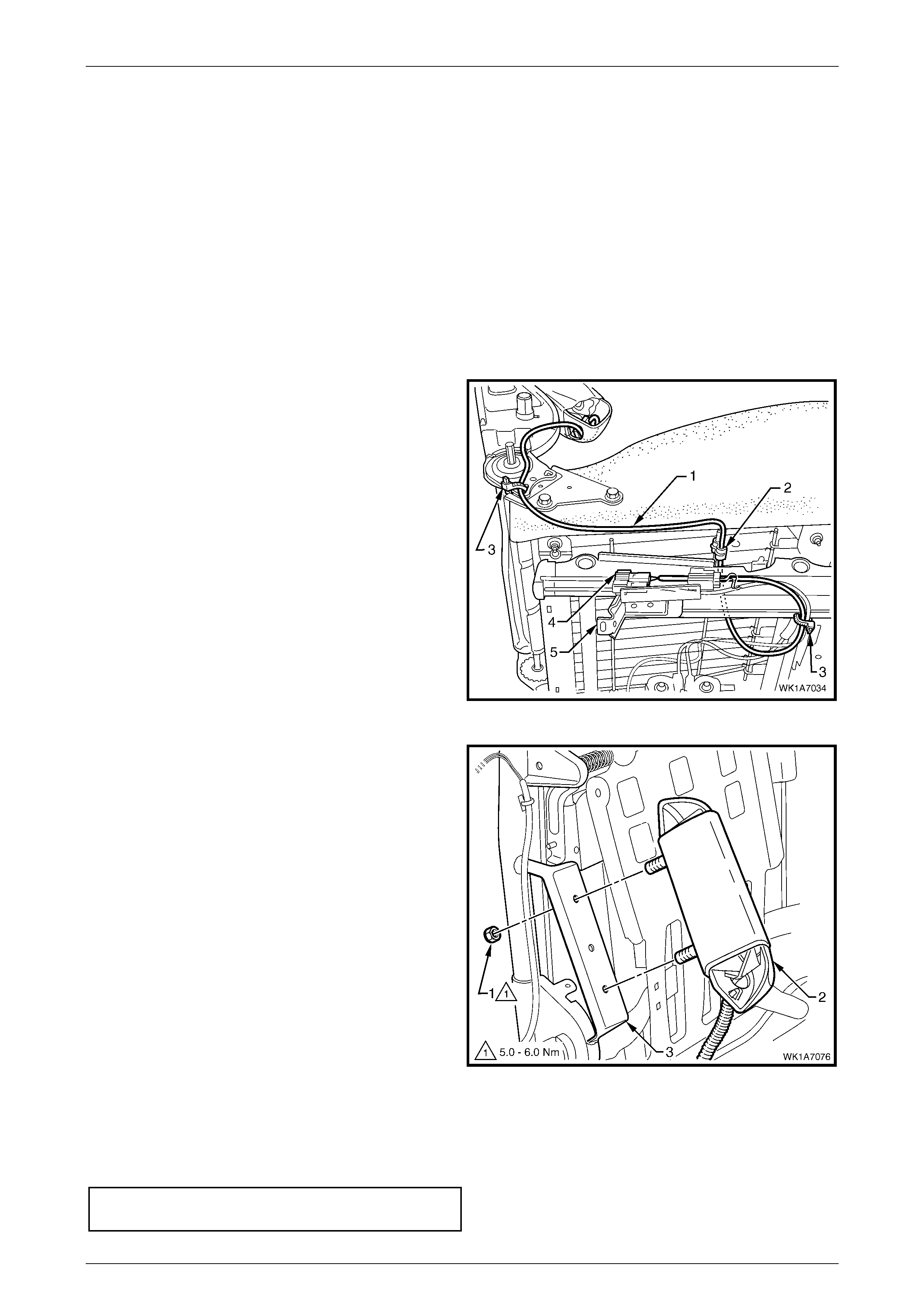
Seat Assemblies Page 1A7–157
Page 1A7–157
Disassemble
As required, remove the following components:
1 Front seat-back rear cover assembly, refer to 4.6 Front Seat-back Rear Cover Assembly.
2 Front seat head restraint assembly, refer to 4.7 Front Seat Head Restraint Assembly.
3 Front seat head restraint sleev es, refer to 4.8 Front Seat Head Restraint Sleeve.
4 Lumbar support knob assembly, refer to 4.9 Lumbar Support Knob Assembly.
5 Front seat-back pad and cover assembly, refer to 4.10 Front Seat-back Pad and Cover Assembly.
Side Impact Airbag Assembly
Remove
1 As required, unclip the side impact airbag wiring
harness (1) from the retaining clip (2) and cut the two
cable ties (3), securing the harness to the front seat
cushion frame assembly, taking care not to damage
the wiring harness.
2 Unclip the wiring harness connector (4) from the track
and height adjust assembly (5).
Figure 1A7 – 134
3 Remove the lock nut (1), two pl aces, attaching the
side impact airbag assembly (2) to the seat-back
frame (3) and airbag assembly.
Figure 1A7 – 135
Reinstall
Reinstallation of the side impact airbag assembly is the reverse of the removal procedure, noting the following:
1 Tighten the nuts to the correct torque specification.
Side impact airbag assembly attaching
nut torque specification .............................. 5.0 – 6.0 Nm

Seat Assemblies Page 1A7–158
Page 1A7–158
Front Seat Dummy Block Insert Assembly
Remove
1 Remove the lock nut (1), two pl aces, attaching the
front seat dummy block insert (2) to the seat-back
frame (3) and remove the dummy block inse rt
assembly.
2 If required, remove the dummy block U-bolt (4) from
the dummy block insert.
Figure 1A7 – 136
Reinstall
Reinstallation of the front seat dummy block insert assembly is the reverse of the removal procedure, noting the
following:
1 Tighten the nuts to the correct torque specification.
Front seat dummy block insert attaching
nut torque specification .............................. 5.0 – 6.0 Nm
Lumbar Support Assembly
Remove
1 Remove the retainer (1), two places, attaching the
lumbar support assembly (2) to the seat-back frame.
Figure 1A7 – 137
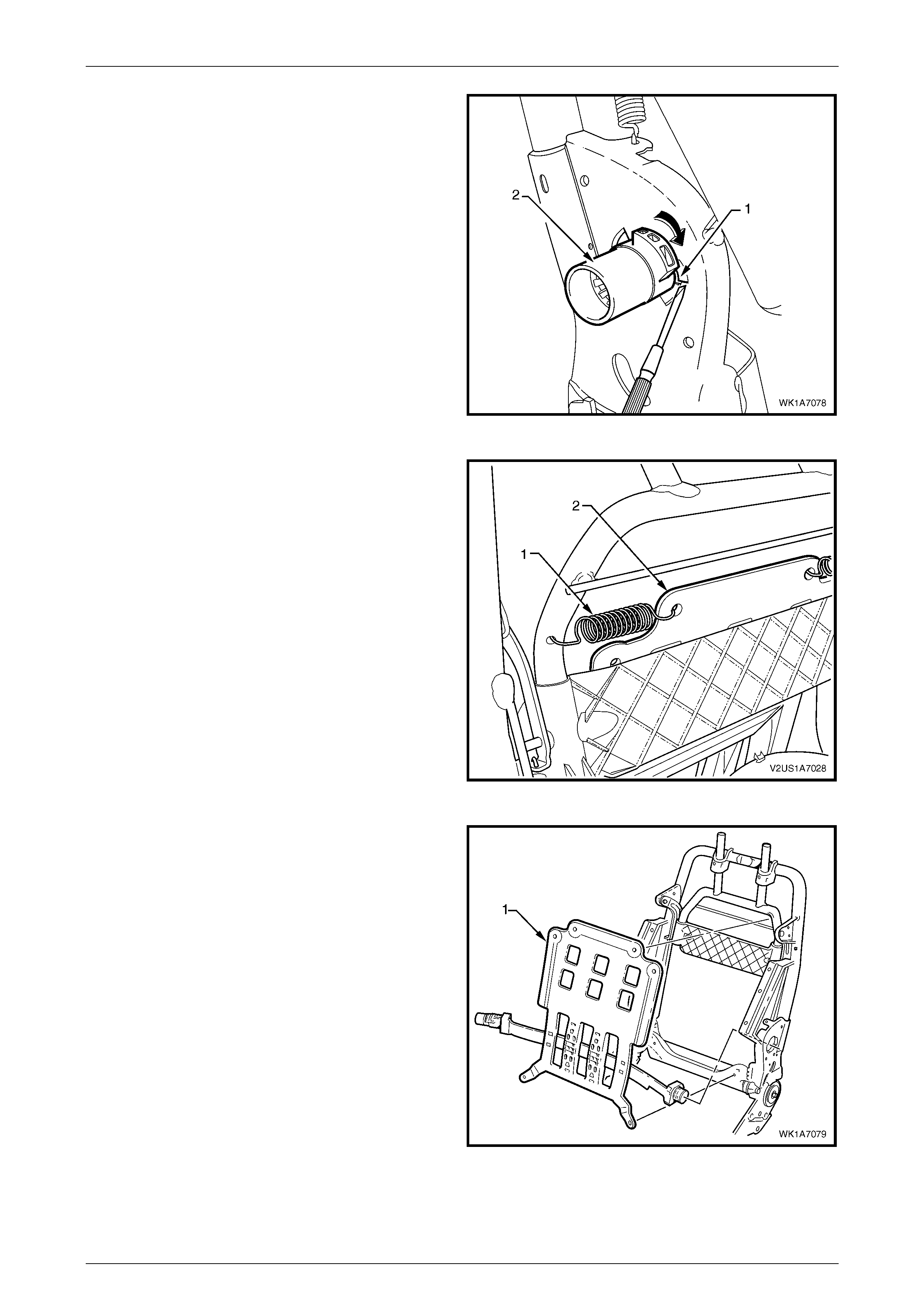
Seat Assemblies Page 1A7–159
Page 1A7–159
2 Depress the retaining tab (1) and from the inner side
of the seat-back frame, rotate the lumbar support shaft
(2) and withdraw from the seat-back frame.
3 Repeat for the opposite side.
Figure 1A7 – 138
4 Disconnect the spring (1), two places, attaching the
lumbar support assembly (2) to the seat-back frame or
active head restraint frame.
TIP
To aid spring removal, pull the support assembly
toward the side that the spring is being removed
to relieve spring tension.
Figure 1A7 – 139
5 Remove the lumbar support assembly (1).
Figure 1A7 – 140

Seat Assemblies Page 1A7–160
Page 1A7–160
Reinstall
Reinstallation of the lumbar support assembly is the reverse of the removal procedure, noting the following:
1 Ensure the lumbar support assembly is correctly seated on the cushion side of the active head restraint frame,
where fitted, with the black lumbar support shaft on the outer side of the seat.
Active Head Restraint Frame As sembly
Remove
1 Remove the screw (1), two places, attaching the active
head restraint frame assembly (2) to the seat-back
frame hinge.
Figure 1A7 – 141
2 Withdraw the active head restraint frame assembly (1)
downward to remove it from the seat-back frame and
remove.
Figure 1A7 – 142
3 If required, slide the support strap (1) from the active
head restraint frame.
Figure 1A7 – 143
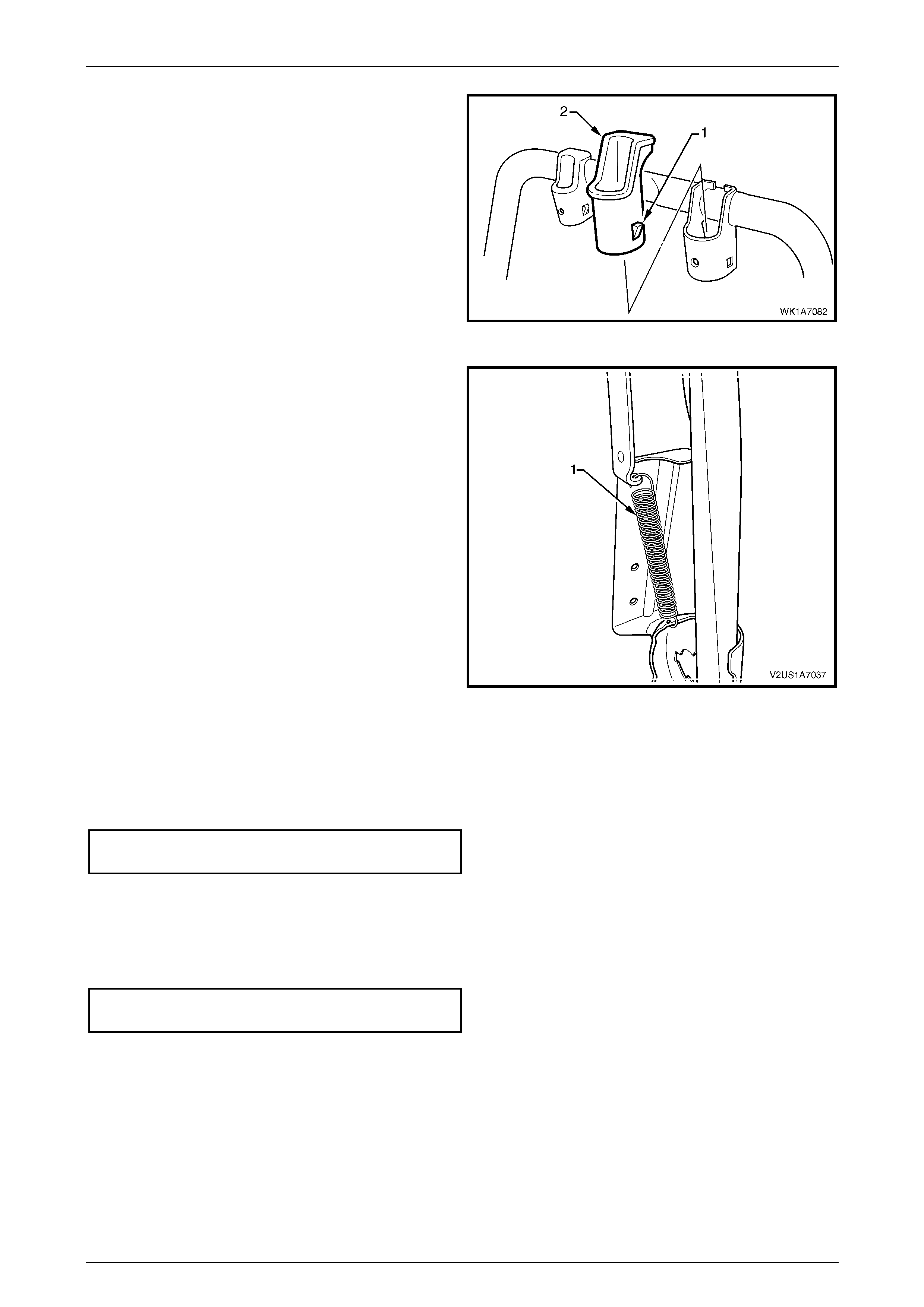
Seat Assemblies Page 1A7–161
Page 1A7–161
4 If required, depress the tab (1), two places, and
withdraw the active head restraint frame sleeve (2)
from the seat-back frame.
5 Repeat for the opposite sleeve as required.
Figure 1A7 – 144
6 If required, remove the spring (1), from the active head
restraint frame hinge and seat-back frame.
7 Repeat for the opposite side as required.
Figure 1A7 – 145
Reinstall
Reinstallation of the active head restraint frame assembly is the reverse of the removal procedure, noting the following:
1 Tighten the screws to the correct torque specification.
Active head restraint frame assembly
attaching screw torque specific ation ........... 3.0 – 5.0 Nm
Reinstall
Reinstallation of the front seat-back frame assembly is the reverse of the removal procedure, noting the following:
1 Tighten the screws to the correct torque specification.
Front seat-back frame assembly
attaching screw torque specific ation ....... 30.0 – 45.0 Nm
2 Check the mechanical and electrical operation of the front seat.
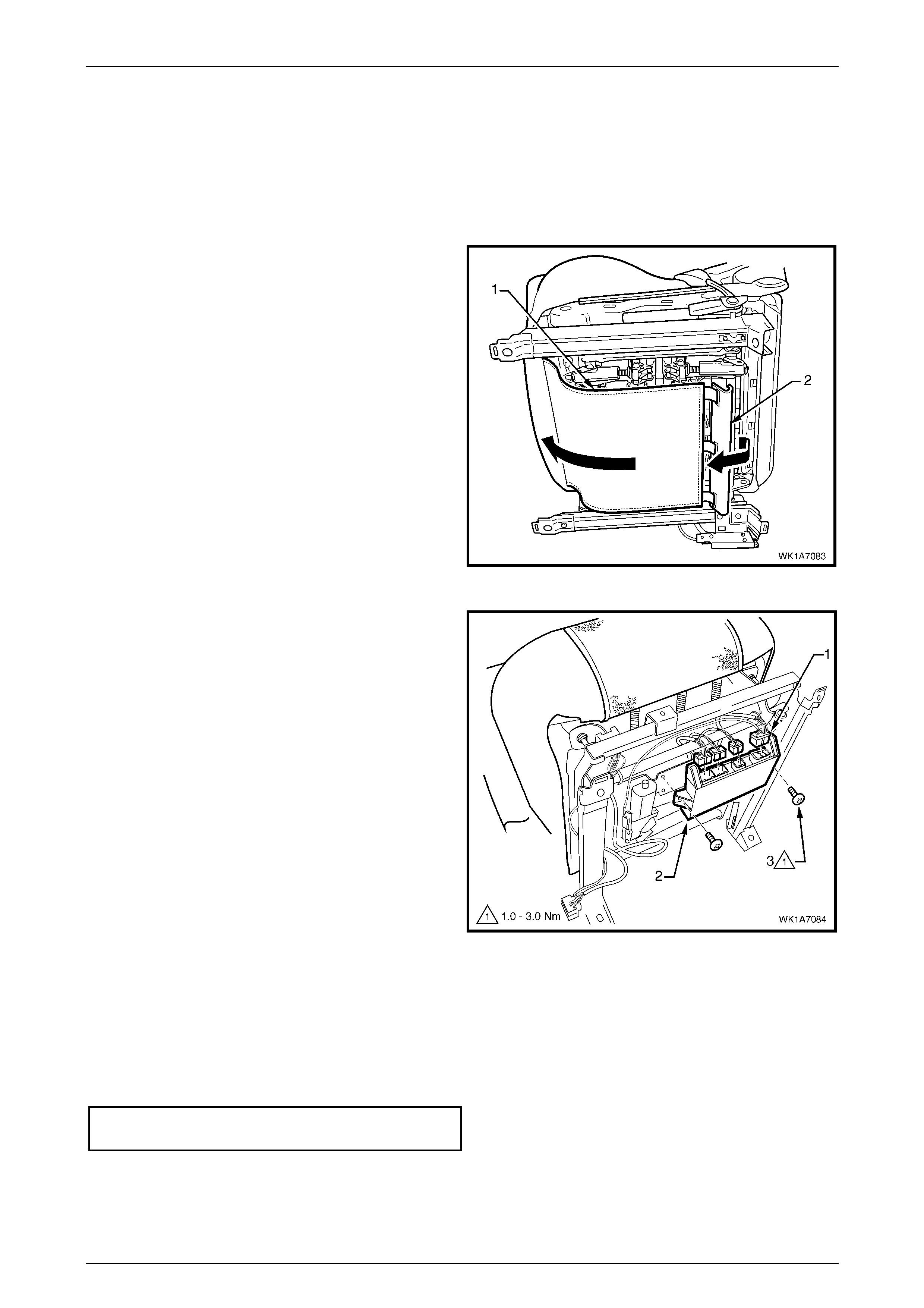
Seat Assemblies Page 1A7–162
Page 1A7–162
4.12 Seat Memory Module
Remove
As required remove the following components:
1 Front seat assembly, refer to 4.3 Front Seat Assemb ly.
2 From under the front seat cushion, disconnect the
front seat cushion cover flap (1), by disengaging the J-
strip (2) located on the rear of the flap.
Figure 1A7 – 146
3 Disconnect the wiring connector (1), four places, from
the seat memory module assembly (2).
4 Remove the screw (3), two places, attaching the seat
memory module to the track and height adjust
assembly.
5 Remove the seat memory module.
Figure 1A7 – 147
Reinstall
Reinstallation of the seat memory module is the reverse of the removal procedure, noting the following:
1 Ensure the connectors are correctly routed and atta ched securely .
2 Tighten the screws to the correct torque specification.
Seat memory mod ule atta chi n g
screw torque specification.......................... 1.0 – 3.0 Nm
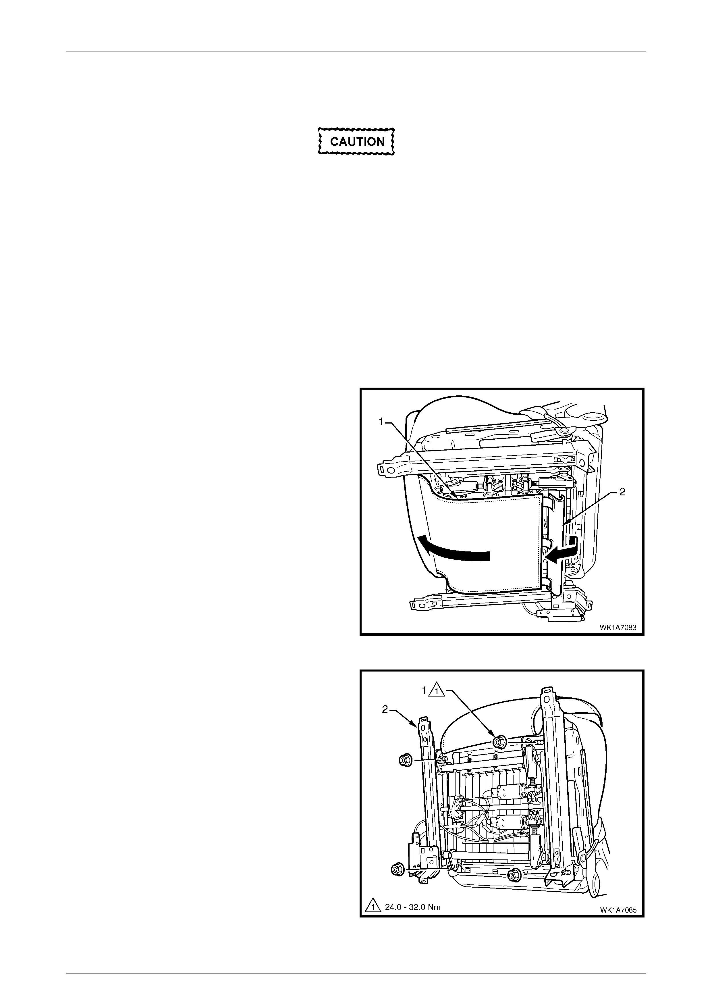
Seat Assemblies Page 1A7–163
Page 1A7–163
4.13 Track and Height Adjust Assembly
The track and height adjust assembly
components are non-serviceable. If the track
and height adjust assembly, drive motors or
drive shafts require replacement, the entire
track and height adjust assembly must be
replaced.
LT Section No. – 14-275
Remove
As required, remove the following components:
1 Front seat assembly, refer to 4.3 Front Seat Assemb ly.
2 Front seat outer side cover, refer to 4.4 Fron t Seat Outer Side C over A ssemb ly.
3 From under the front seat cushion, disconnect the
front seat cushion cover flap (1), by disengaging the J-
strip (2) located on the rear of the flap.
4 As required, unattach the seatbelt pretensioner, side
impact airbag and DVD display wiring harnesses.
Figure 1A7 – 148
5 Remove the four nuts (1) attaching the track and
height adjust assembly (2) to the seat.
6 Remove the track and height adjust assembly.
7 If required, remove the seatbelt buckle and
pretensioner assembly, refer to Section 12M ,
2 Service Operations – Seatbelts.
Figure 1A7 – 149

Seat Assemblies Page 1A7–164
Page 1A7–164
Reinstall
Reinstallation of the track and height adjust assembly is the reverse of the removal procedure, noting the following:
1 Ensure the connectors are correctly routed and atta ched securely .
2 Tighten the nuts to the correct torque specification.
Track and height adjust assembly
attaching nut torque specification........... 24.0 – 32.0 Nm
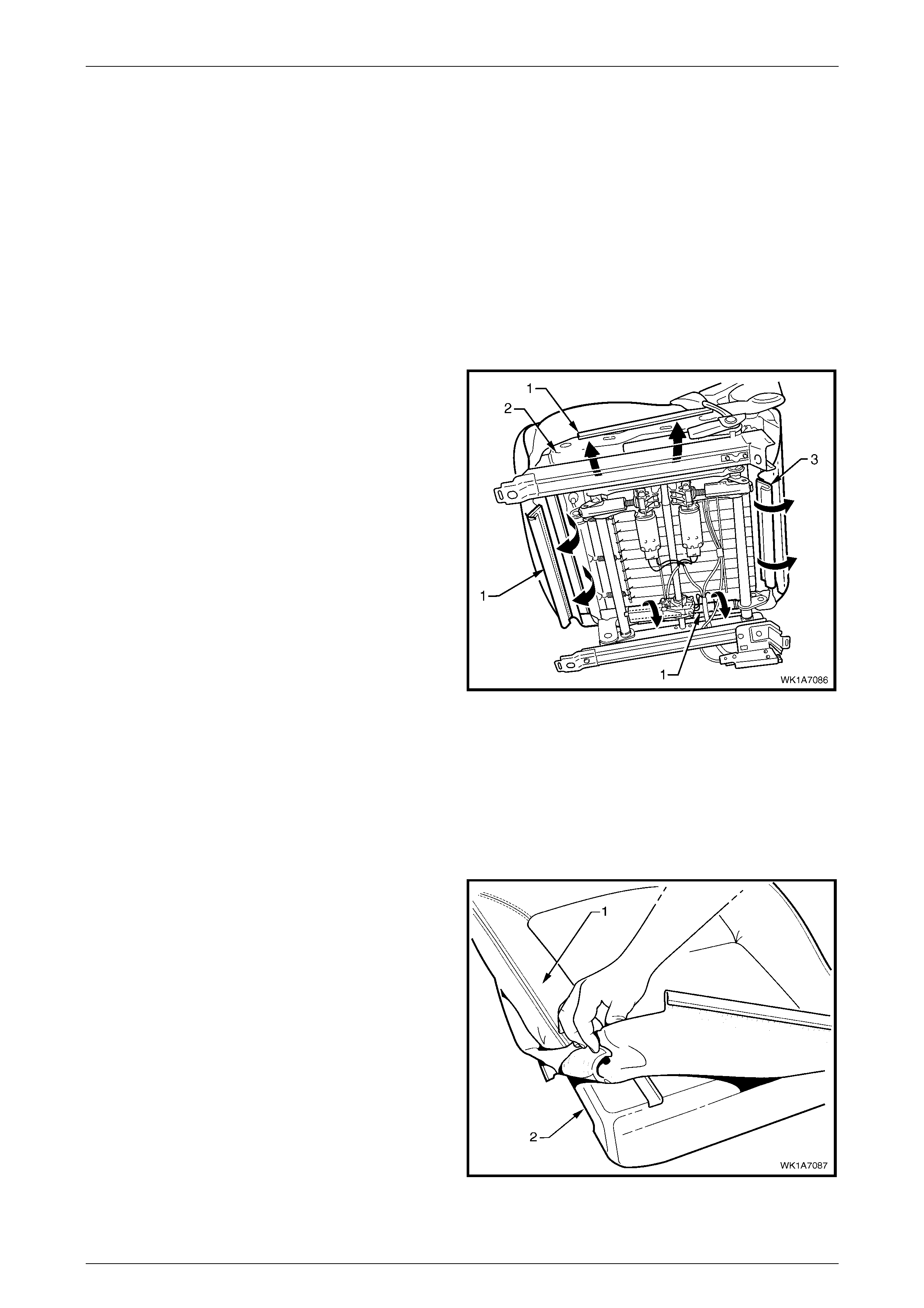
Seat Assemblies Page 1A7–165
Page 1A7–165
4.14 Front Seat Cushion Pad and Cover
Assembly
LT Section No. – 14-295
As required, remove the following components:
1 Front seat assembly, refer to 4.3 Front Seat Assemb ly.
2 Front seat outer side cover, refer to 4.4 Fron t Seat Outer Side C over A ssemb ly.
3 Front seat inner side cover, refer to 4.5 Front Seat Inner Side Cover.
4 Front seat-back frame assembly, refer to 4 .11 F ront Seat-back Frame Assembl y.
Remove
1 From under the front seat cushion, disengage the front
and side J-strips (1) away from the seat frame (2).
2 Lift the cover and pad assembly away from the seat
frame and then release the rear J-strip (3).
3 Remove the cover and pad assembly.
Figure 1A7 – 150
Disassemble NOTE
The following illustrations show typical hook and
loop arrangement, which will vary according to
seat type.
Surebond type seat-back cover and pad
assemblies cannot be disassembled.
1 Fold the rear corners of the seat cushion cover (1)
over the seat cushion pad (2).
Figure 1A7 – 151
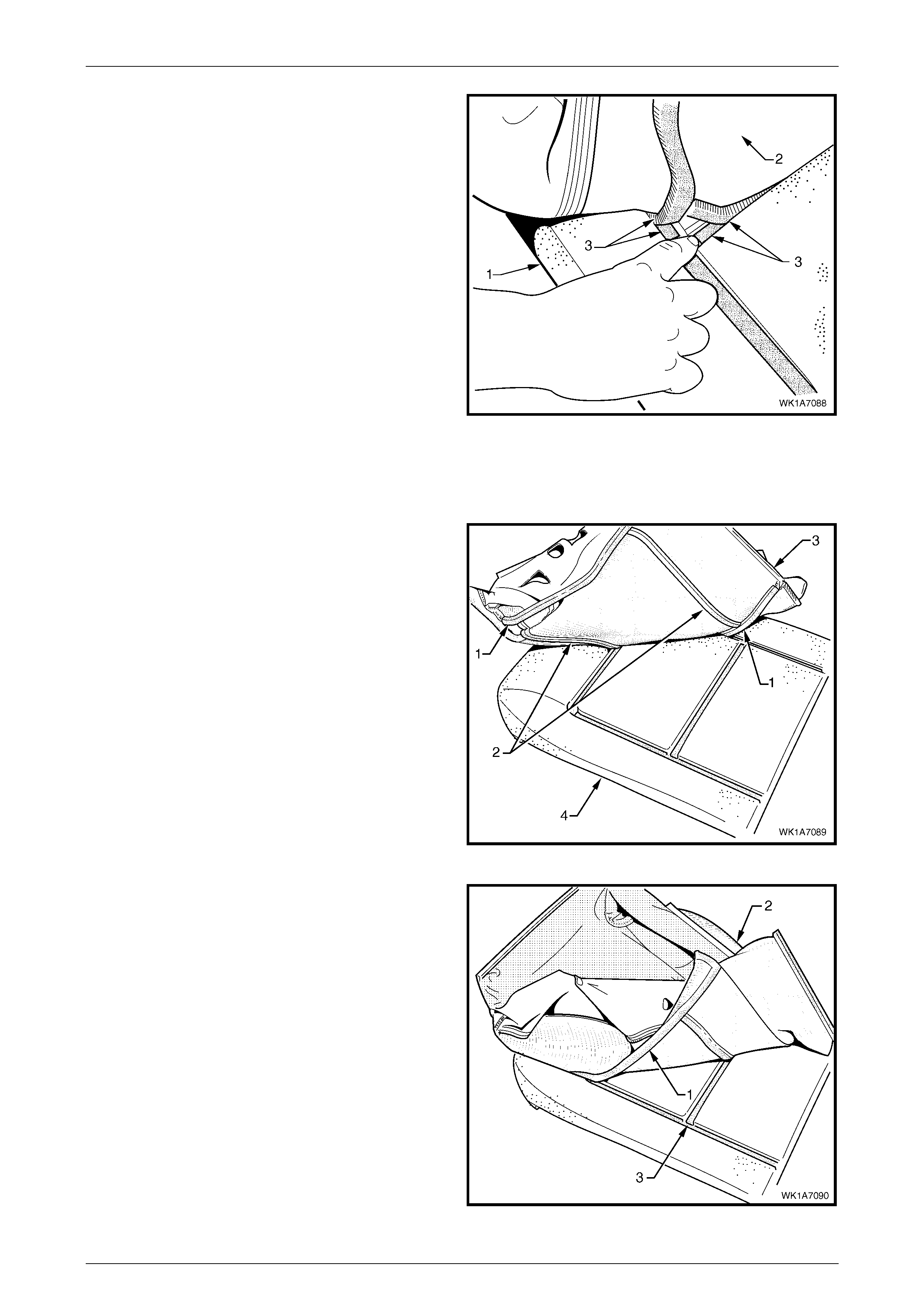
Seat Assemblies Page 1A7–166
Page 1A7–166
2 While holding the front seat cushion pad (1), pull the
rear corners of the seat cushion cover (2) forward and
away from the front seat cushion pad to disengage the
hook and loop strips (3).
3 Pull the front seat cover up and over the forward edge
of the front seat cushion pad.
Figure 1A7 – 152
Reassemble
Reassembly of the seat cushion pad is the reverse of the disassembly procedure noting the following:
1 Align either of the outer hook and loop strips (1) and
the one or two cross hook and loop strips (2), on the
seat cushion cover (3), with the seat cushion pad (4).
2 Press the folded edge of the rear seat cushion cover
firmly into the corresponding groove in the seat
cushion pad to engage the hook and loop strip.
Figure 1A7 – 153
3 Align and press the outer hook and loop strip (1), on
the seat cushion cover (2), with the corresponding
groove in the seat cushion pad (3).
Figure 1A7 – 154
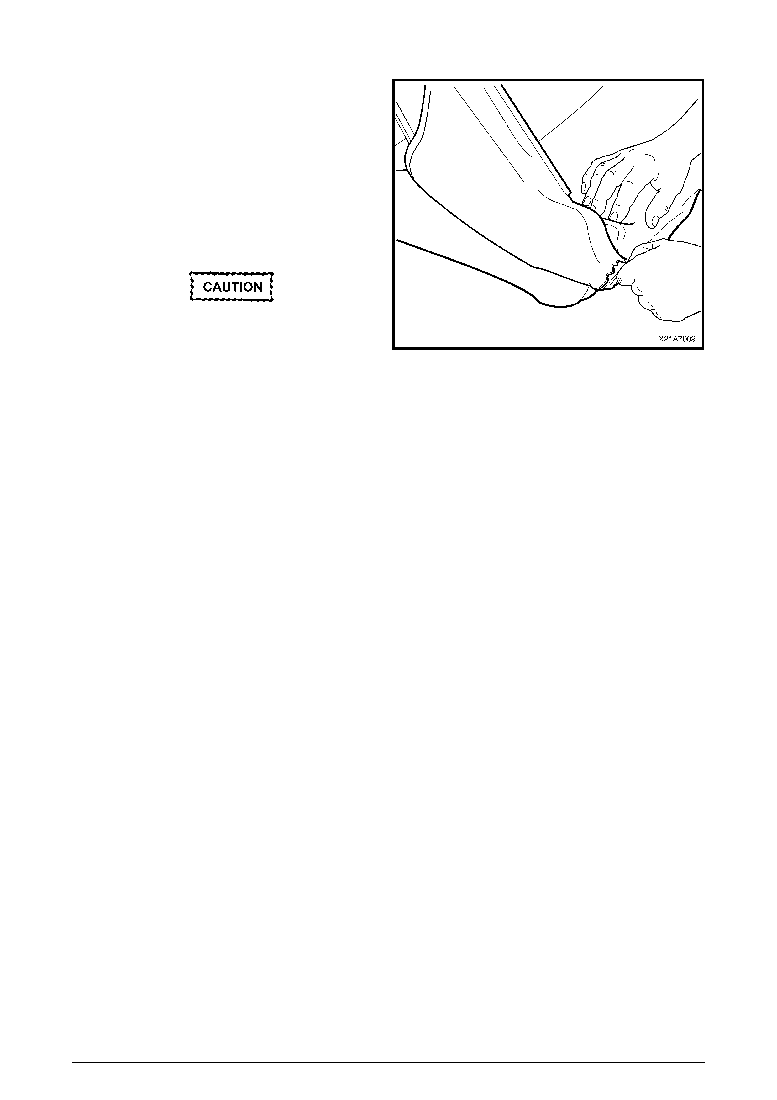
Seat Assemblies Page 1A7–167
Page 1A7–167
4 Roll the front corners of the front seat cushion cover
over the seat cushion pad.
5 Roll the sides of the seat cushion cover over the seat
cu shion pad.
6 Roll the rear corners of the seat cushion cover over
the seat cushion pad.
NOTE
Make sure the pad is fitted neatly by hand into all
corners and contours of the seat cover.
Do not pull the cover onto the pad from
underneath using the J-strip to make it fit
neatly, as the fabric may be damaged.
Figure 1A7 – 155
Reinstall
Reinstallation of the front seat cushion pad and cover assembly is the reverse of the removal procedure.
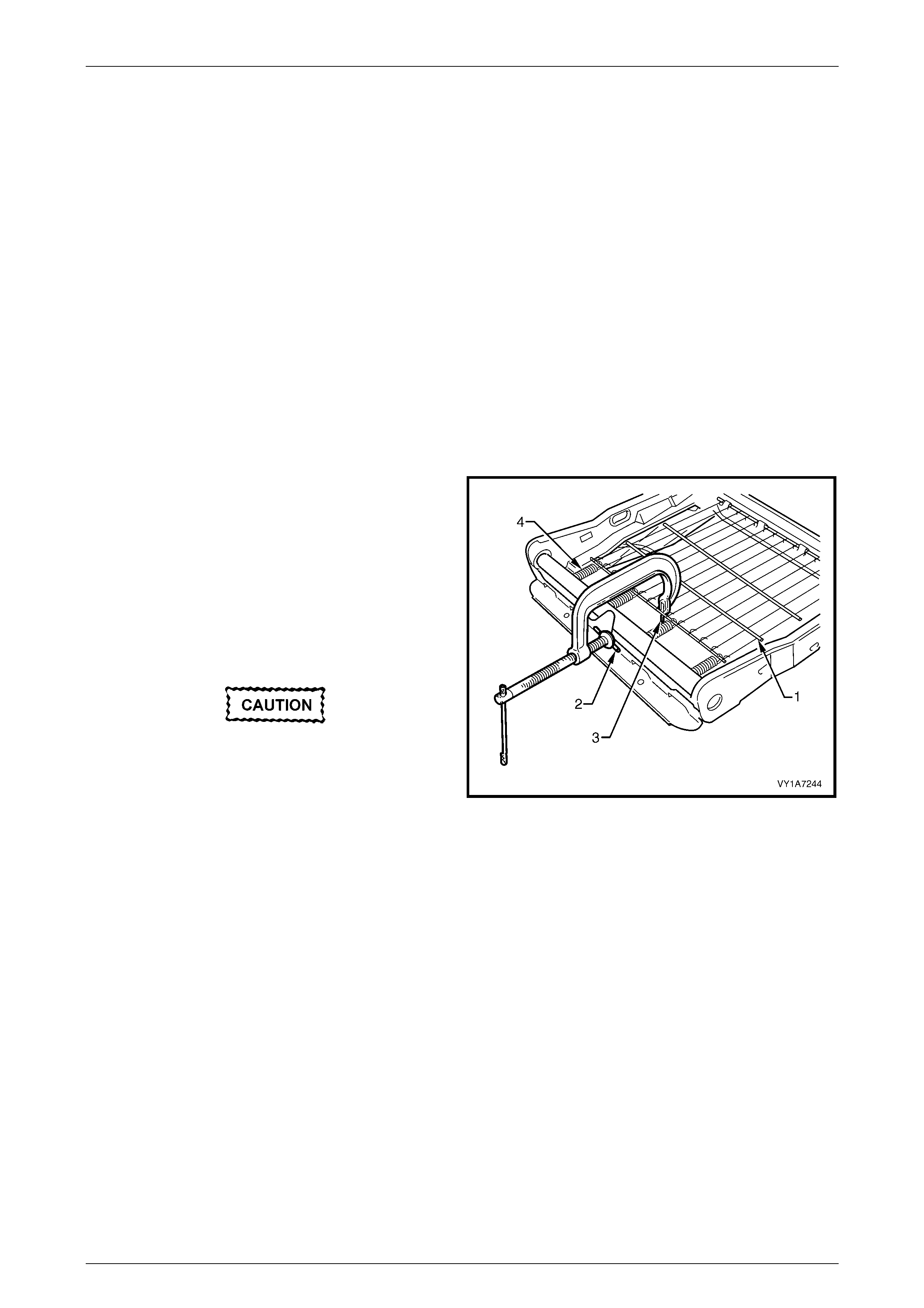
Seat Assemblies Page 1A7–168
Page 1A7–168
4.15 Front Seat Cushion Frame Assembl y
LT Section No. – 14-275
Remove
As required remove the following components:
1 Front seat assembly, refer to 4.3 Front Seat Assemb ly.
2 Front seat outer side cover, refer to 4.4 Fron t Seat Outer Side C over A ssemb ly.
3 Front seat inner side cover, refer to 4.5 Front Seat Inner Side Cover.
4 Front seat-back frame assembly, refer to 4 .11 Front S eat-B ack Frame A s semb ly.
5 Track and height adjust assembly, refer to 4.13 Track and Height Adjust Assembly.
6 Front seat cushion pad and cover assembly, refer to 4.14 Front Seat Cushion Pad and Cover Assembly.
Disassemble
1 To remove the suspension mat (1), modify a G-clamp
with a 5mm diameter metal dowel (2) welded to one
end, approximately 40mm long and with a 2mm
diameter pin (3) approximately 20mm long welded to
the other end.
2 Using the G-clamp, stretch the suspension mat far
enough to allow for the retaining springs (4) to be
removed from the seat cush io n frame.
3 Back the G-clamp load off and remove the suspension
mat.
When using the G-clamp, use existing holes
in the suspension mat to ensure that the mat
deformation does not occur.
Figure 1A7 – 156
Reassemble
Reassembly of the suspension mat is the reverse of the disassembly procedure.
Reinstall
Reinstallation of the front seat cushion frame assembly is the reverse of the removal procedure, noting the following:
1 Ensure all wiring is correctly connected and routed, refer to Section 12O, Fuses, Relays and Wiring Harnesses.
2 Check the mechanical and electrical operation of the front seat.

Seat Assemblies Page 1A7–169
Page 1A7–169
4.16 Front Seat Lift Motor Assemblies
The front seat lift motor assemblies are non-servic eable items.
If a front seat lift motor assembly requires replacement, the track and height adjust assembly must be replaced, refer to
4.13 Track and Height Adjust Assembly.

Seat Assemblies Page 1A7–170
Page 1A7–170
4.17 Front Seat Fore/Aft Movement Motor
Assembly
The front seat fore/aft movement motor assembly and potentiometer are non-serviceable items.
If the front seat fore/aft movement motor or drive shafts require replacement, the track and height adjust assembly must
be replaced, refer to 4.13 Track and Height Adjust Assembly.

Seat Assemblies Page 1A7–171
Page 1A7–171
4.18 Front Seat-back Recline Motor Assembl y
The front seat-back recline motor assembly is a non-serviceable item.
If the front seat-back recline motor assembly requires replacement, the front seat-back frame assembly must be
replaced, refer to 4.11 Front Seat-back Frame Asse mbly .

Seat Assemblies Page 1A7–172
Page 1A7–172
4.19 Drive Motor Potentiometers
The front seat drive motor potentiometers are non-serviceable items.
If the front seat fore/aft movement, seat-back recline and/or front seat lift motor potentiometers require replacement, the
track and height adjust assembly must be replaced, refer to 4.12 Track and Height Adjust Assembly.

Seat Assemblies Page 1A7–173
Page 1A7–173
5 Diagnostics – Front Seat,
Level 2, 4 and 5
This Section provides charts to assist in the diagnosis and repair of front seats. Refer to 4.1 Front Seat Usage Chart,
Level 2, 4 and 5, for a full listing of the different types of seats fitted to vehicles. Included in that Section are illustrated
parts breakdowns of the various seats.
5.1 Prerequisites
Safety Requirements
When operating the seat as part of any of the Steps in the diagnosis charts, ensure that fingers and limbs are clear of
moving parts.
Equipment
The followi ng equipment is required to diagnose the seats:
1 An unpowered test lamp with a current draw of less than 3 A.
2 A digital multimeter with a minimum impedance of 10 MΩ.
Testing Procedures
The following points must be adhered to when performing diagnostic testing on components:
1 Care must be taken when using testing equipment to diagnose wiring harness connectors. It is preferred that the
technician bac k probe the connector to avoid terminal dama ge.
2 When tests are required on connector terminals, utilise the adapters in the connector adaptor kit KM–609 to
prevent damage to the terminals.
3 Unless the multimeter being us ed has an auto-ranging function, ensure that the correct range is selected.
4 When back-probing connectors, ensure the test lamp ground lead is connected to a suitable ground point on the
vehicle. Ensure that this ground point is not part of the circuit being tested.
NOTE
When following the Steps in the diagnosis charts,
the exact order of Steps should be observed. If
the required nominal value or result is not
achieved at any stage, the problem must be
rectified before proceeding any further.

Seat Assemblies Page 1A7–174
Page 1A7–174
5.2 Mechanical Diagnosis
Lumbar Support Inoperative
Introduction
This test is used by the technician to aid in the diagnosis of the lumbar support assembly.
Test Description
The following numbers refer to the Step numbers in the diagnostic chart.
1 Checks that the lumbar support knob is properly engaging the lumbar support adjuster. Check the knob for cracks
and worn splines.
2 Checks that the lumbar support adjust assembly is not damaged or worn.
3 Checks that there is correct operation of the lumbar support assembly when the lumbar support knob is turned
throughout its range.
Step Action Yes No
1 1 Remove the lumbar support knob, refer to
4.9 Lumbar Support Knob Assembly.
Is the lumbar support knob serviceable? Go to Step 2.
Replace the lumbar support
knob.
Refer to 4.9 Lumbar Support
Knob Assembly.
2 1 Remove the front seat-back cover
assembly, refer to 4.6 Front Seat-back
Rear Cover Assemb ly.
2 Visually inspect the lumbar support and
strap.
Is the lumbar support assembly serviceable?
Go to Step 3.
Replace the lumbar support
assembly.
Refer to 4.11 Front Seat-back
Frame Assemb ly.
3 1 Refit the lumbar support knob and operate
as required.
Does the strap attachment move along the shaft
freely in both directions?
Does the strap tighten and loo sen?
System servic eabl e.
Replace the lumbar support
assembly.
Refer to 4.11 Front Seat-back
Frame Assemb ly.
When all diagnosis and repairs are completed, check the system for correct operation.

Seat Assemblies Page 1A7–175
Page 1A7–175
5.3 Electrical Diagnosis – Eight-way Seat,
Non-memory, RHD
The charts in this Section are used by the technician in the aid of diagnosing faults on eight-way, non-memory seat
assemblies. To aid in the use of the diagnosis charts, refer to Wiring Diagram – Eight-way Seat, Non-memory, RHD and
Connector Chart – Eight-way Seat, Non-memory, RHD in this Section.

Seat Assemblies Page 1A7–176
Page 1A7–176
Wiring Diagram – Eight-way Seat, Non-memory, RHD
Figure 1A7 – 157
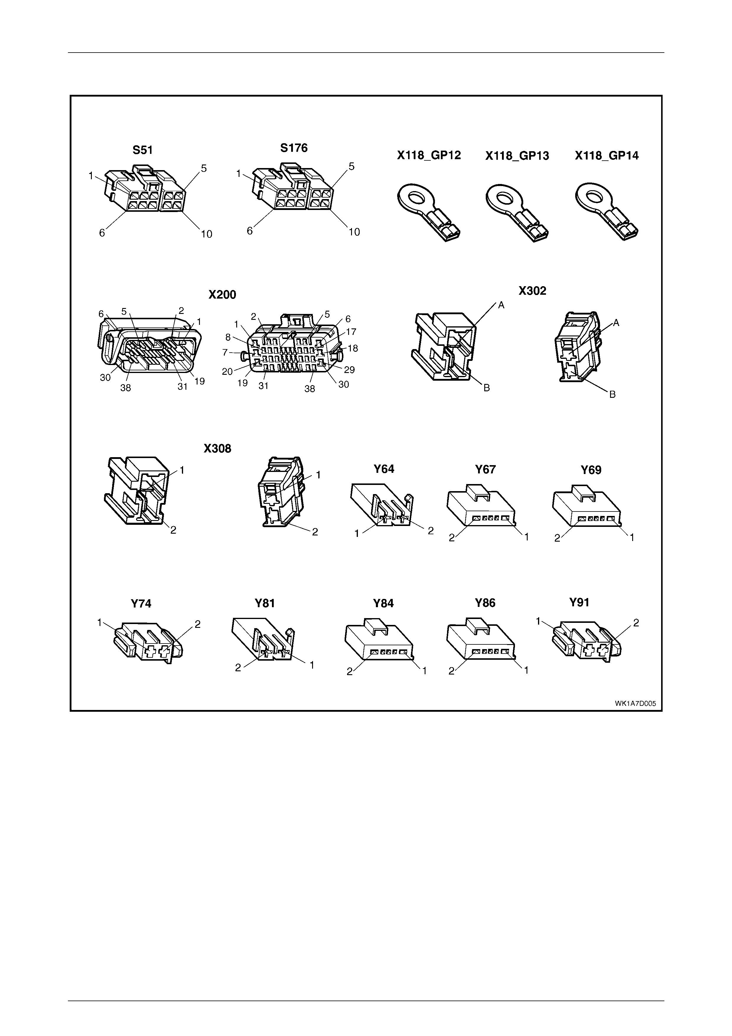
Seat Assemblies Page 1A7–177
Page 1A7–177
Connector Chart – Eight-wa y Seat, Non-m emory, RHD
Figure 1A7 – 158

Seat Assemblies Page 1A7–178
Page 1A7–178
Neither Seat Adjustment Switch Functions Operate
Introduction
This test is used by the technician to aid in the diagnosis of the seat power and ground circuits, if neither seat operates
when either seat adjustment switch is operated.
Test Description
The following numbers refer to the Step numbers in the diagnostic chart.
1 Checks that battery voltage is more than 11.5 volts. The seat motors require more than 11.5 volts to operate
correctly.
2 Checks that circuit breaker F2 located on the passenger compartment fuse and relay panel assembly is not tripped.
Isolates whether circuit breaker F2 is the fault affecting the circuit between the battery and connector X200 pin 19.
3 Checks that fusible link F105 located on the engine compartment fuse and relay panel assembly is serviceable.
Isolates whether the fusible link is the fault affecting the circuit between the battery and connector X200 pin 19.
4 Ensures that connector X200 is secure.
5 Checks whether there is battery voltage at connector X200 pin 19. Isolates whether the fault is between the battery
and connector X200 pin 19. If the fault in the circuit is between connectors X200 pin 19 and either X308 pin B or
X302 pin B, only one seat will not operate.
6 Checks whether there is battery voltage at circuit breaker F2. Isolates whether the fault is between the battery and
circuit breaker F2 or circuit breaker F2 and connector X200 pin 19.
7 Checks whether there is battery voltage at fusible link F105. Isolates whether the fault is between the battery and
fusible link F105 or fusible link F105 and circuit breaker F2.
8 Checks that all the ground points associated with the system are serviceable and a good ground is provided at
each point.
Step Action Yes No
1 1 Check the battery voltage, refer to Section
12A, 2.9 Battery.
Is the battery voltage more than 11.5 V? Go to Step 2. Refer to Section 12A,
2.9 Battery for further
diagnosis.
2 1 Inspect circuit breaker F2, refer to Section
12O, 2.2 Circuit Breakers.
Is circuit breaker F2 tripped?
Allow the circuit breaker to
reset, refer to Section 12O,
2.2 Circuit Breakers. Go to Step 3.
3 1 Inspect fusible link F105, refer to Section
12O, 2.3 Fusible Links.
Is fuse F105 serviceable? Go to Step 4. Replace the fusible link.
4 Is connector X200 secure? Go to Step 5. Ensure that the connector is
secure.
5 1 Back probe connector X200 pin 19 with a
test lamp.
Does the test lamp illuminate? Go to Step 8. Go to Step 6.
6 1 Remove circuit breaker F2 from the
passenger comp artm ent fus e and relay
panel assembly.
2 Using a test lamp, probe connector
X129 – X4 5 pin – 2. Refer to Section 12P
Wiring Diagrams.
Does the test lamp illuminate?
There is a fault in circuit 540
between circ uit breaker F2 and
connector X200 pin 19.
Repair or replace circ uit 540.
Go to Step 7.

Seat Assemblies Page 1A7–179
Page 1A7–179
Step Action Yes No
7 1 Remove fusible link F105.
2 Using a test lamp, probe connector
X18-105. Refer to Section 12P Wiring
Diagrams.
Does the test lamp illuminate?
There is a fault in circuit 342
between fusible link F105 and
circuit breaker F2.
Repair or replace circuit 342.
There is a fa ult in circ uit 1
between the battery and
fusible link F105.
Repair or replace circuit 1.
8 1 Ensure that the following ground points are
secure and have good contact with the
vehicle structure:
• X118–GP12 located in the middle of
the transmission tunnel.
• X118–GP13 located in the rear
compartment on the right-hand side
tail lamp stud.
• X118–GP14 located on the rear
compartment lid .
Refer to Section 12P Wiring Diagrams for further
details of ground ing poi nts.
Are all the ground points secure to the vehicle
with a good contact?
There is a fault in circuit 650.
Repair or replace circuit 650.
Ensure that the connectors are
secured to the vehicle and that
there is a good contact
between the conne ctor and th e
vehicle.
When all diagnosis and repairs are completed, check the system for correct operation.

Seat Assemblies Page 1A7–180
Page 1A7–180
None of the Driver’s Seat Adjustment Switch Functi ons Operate
Introduction
This test is used by the technician to aid in the diagnosis of the driver’s seat adjustment switch when none of the switch
functions operate. The test diagnoses the driver’s seat adjustment switch and associated power and ground circuits.
Test Description
The following numbers refer to the Step numbers in the diagnostic chart.
1 Checks whether all of the passenger seat functions wo rk. If none of them work, the fault is not isolated to the
driver’s seat only .
2 Checks whether there is battery power at connector X302 pin B. Isolates whether there is a fault in circuit 540
between connectors X200 pin 19 and X302 pin B.
3 Checks that all the connectors required for the seat to operate effectively are in place and positively connected.
4 Checks whether there is battery power at connector S51 – X1 pin 5. Isolates whether there is a fault in ci rcuit 540
between connectors S51 – X1 pin 5 and X302 pin B.
5 Checks whether the driver’s seat adjustment switch is serviceable.
6 Checks whether there is continuity between connectors S51 – X1 pin 1 and X302 pin A which supplies the ground
circuit for the driver’s seat adjustment switch. Isolates whether there is a fault in circuit 650 between the switch and
connector X302 pin A or between connector X302 pin A and the grounding points.
Step Action Yes No
1
A
re all of the passenger’s seat adjustment switch
functions inoperative? Refer to Neither Seat
Adjustment Switc h Functions
Operate in this Section. Go to Step 2.
2 1 Back probe connector X302 pin B with a
test lamp.
Does the test lamp illuminate? Go to Step 3.
There is a fault in circuit 540
between connectors
X200 pin 19 and X302 pin B.
Repair or repl ace circuit 540.
3 Are the following connectors secure?
• S51
• X302
• Y64
• Y67
• Y69
• Y74
Go to Step 4. Ensure that the connectors are
secure.
4 1 Back probe connector S51 – X1 pin 5 with
a test lamp.
Does the test lamp illuminate? Go to Step 5.
There is a fault in circuit 540
between connectors
S51 – X1 pin 5 and X302 pin
B.
Repair or repl ace circuit 540.
5 1 Remove the driver’s seat adjustment
switch from the seat, re fer to 4.4 Front
Seat Outer Side Cover Assembly.
2 Test the driver’s seat adjustment switch,
refer to 5.5 Eight-way Seat Adjustment
Switch Test.
Is the driver’s seat adjustment switch
serviceable?
Go to Step 6.
Replace the driver’s seat
adjustment switch.
Refer to 4.4 Front Seat Outer
Side Cover Assembly.

Seat Assemblies Page 1A7–181
Page 1A7–181
Step Action Yes No
6 1 Back probe connector X302 pin A with a
test lamp.
2 Operate the driver’s seat adjustment switch
in any of the available directions.
Does the test lamp illuminate?
There is a fault in circuit 650
between connector X302 pin A
and ground points X118–
GP12, X118–GP13 and X118–
GP14.
Repair or replace circuit 650.
There is a fault in circuit 650
between connectors
S51 – X1 pin 1 and X302 pin
A.
Repair or repl ace circuit 650.
When all diagnosis and repairs are completed, check the system for correct operation.

Seat Assemblies Page 1A7–182
Page 1A7–182
Front/Rear of the Driver’s Seat Does Not Raise and/or Lower
Introduction
This test is used by the technician to aid in the diagnosis of the front and/or the rear of the driver’s seat not raising and/or
lowering. The test diagnoses the seat adjustment switch and the motor circuits.
Test Description
The following numbers refer to the Step numbers in the diagnostic chart.
1 Checks whether the driver’s seat adjustment switch operates the seat in any direction. Isolates whether the power
and ground circuits are at fault.
2 Checks that all the connectors required for the seat to operate effectively are in place and positively connected.
3 Checks whether the driver’s seat adjustment switch is serviceable.
4 Confirms whether the rear of the seat raises or lowers. Isolates whether the rear lift motor and circuit of the seat is
the fault.
5 Confirms whether the front of the seat raises or lowers. Isolates whether the front lift motor and circuit of the seat is
the fault.
6 Checks whether there is battery powe r to the seat rear lift motor at connector Y69 – X1 pin 1. Isolates whether
there is a fault in circuit 282 that supplies battery power to the motor to raise the rear of the seat.
7 Checks whether there is battery power to the seat rear lift motor at connector Y69 – X1 pin 2. Isolates whether the
fault is in circuit 283 that supplies battery power to the motor to lower the rear of the seat or the motor is faulty. As
the direction of the motor is changed by reversing the polarity, this Step also confirms that the ground circuit from
Step 6 is serviceable.
8 Checks whether there is battery power to the seat front lift motor at connector Y67 – X1 pin 1. Isolates whether
there is a fault in circuit 286 that supplies battery power to the motor to raise the front of the seat.
9 Checks whether there is battery power to the seat front lift motor at connector Y67 – X1 pin 2. Isolates whether the
fault is in circuit 287 that supplies battery power to the motor to lower the front of the seat or the motor is faulty. As
the direction of the motor is changed by reversing the polarity, this Step also confirms that the ground circuit from
Step 8 is serviceable.
Step Action Yes No
1 Does the driver’s seat adjustment switch operate
the seat correctly in any of the eight directions? Go to Step 2.
Refer to None of the Driver’s
Seat Adjustment Switch
Functions Operate in this
Section.
2 Are the following connectors secure?
• S51
• Y67
• Y69
Go to Step 3. Ensure that the connectors are
secure.
3 1 Remove the driver’s seat adjustment
switch from the seat, re fer to 4.4 Front
Seat Outer Side Cover Assembly.
2 Test the driver’s seat adjustment switch,
refer to 5.5 Eight-way Seat Adjustment
Switch Test.
Is the driver’s seat adjustment switch
serviceable?
Go to Step 4.
Replace the driver’s seat
adjustment switch.
Refer to 4.4 Front Seat Outer
Side Cover Assembly.
4 1 Operate the driver’s seat adjustment switch
to raise or lower the rear of the seat.
Does the rear of the seat raise and lower? Go to Step 5. Go to Step 6.

Seat Assemblies Page 1A7–183
Page 1A7–183
Step Action Yes No
5 1 Operate the driver’s seat adjustment switch
to raise or lower the front of the seat.
Does the fron t of the seat raise and lower? System serviceable. Go to Step 8.
6 1 Back probe connector Y69 – X1 pin 1 with
a test lamp.
2 Operate the driver’s seat adjustment switch
to raise the rear of the seat.
Does the test lamp illuminate?
Go to Step 7.
There is a fault in circuit 282
between connectors
S51 – X1 pin 9 and
Y69 – X1 pin 1.
Repair or repl ace circuit 282.
7 1 Back probe connector Y69 – X1 pin 2 with
a test lamp.
2 Operate the driver’s seat adjustment switch
to lower the rear of the seat.
Does the test lamp illuminate?
The seat rear lift motor is
faulty.
Replace the seat rear lift
motor, refer to 4.16 Front Seat
Lift Motor Assemblies.
Go to Step 5.
There is a fault in circuit 283
between connectors
S51 – X1 pin 8 and
Y69 – X1 pin 2.
Repair or repl ace circuit 283.
Go to Step 5.
8 1 Back probe connector Y67 – X1 pin 1 with
a test lamp.
2 Operate the driver’s seat adjustment switch
to raise the front of the seat.
Does the test lamp illuminate?
Go to Step 9.
There is a fault in circuit 286
between connectors
S51 – X1 pin 10 and
Y67 – X1 pin 1.
Repair or repl ace circuit 286.
9 1 Back probe connector Y67 – X1 pin 2 with
a test lamp.
2 Operate the driver’s seat adjustment switch
to lower the front of the seat.
Does the test lamp illuminate?
The seat front lift motor is
faulty.
Replace the seat front lift
motor, refer to 4.16 Front Seat
Lift Motor Assemblies.
There is a fault in circuit 287
between connectors
S51 – X1 pin 7 and
Y67 – X1 pin 2.
Repair or repl ace circuit 287.
When all diagnosis and repairs are completed, check the system for correct operation.

Seat Assemblies Page 1A7–184
Page 1A7–184
Driver’s Seat Fore/Af t Movement Function is Inoperative or Not Smooth
Introduction
This test is used by the technician to aid in the diagnosis of the fore/aft movement function of the driver’s seat being
inoperative or the action of the seat through the range of movement is not sm ooth. The test diagnoses the seat
adjustment switch and the motor circuits.
Test Description
The following numbers refer to the Step numbers in the diagnostic chart.
1 Checks whether the driver’s seat adjustment switch operates the seat in any direction. Isolates whether there is
battery power to the switch assembly.
2 Checks that there are no items obstructing the guide rails, which may stop or hinder the seat movement.
3 Checks that the guide rails and drive shafts have adequate lubricant applied to provide a smooth operation of the
seat.
4 Checks that the guide rails or drive shafts have not been damaged. Any binding between the mo ving parts will
result in poor operation of the fore and aft movement.
5 Checks that all the connectors required for the seat to operate effectively are in place and positively connected.
6 Checks whether the driver’s seat adjustment switch is serviceable.
7 Checks whether there is battery power to the seat fore/aft movement motor at connector Y64 – X1 pin 1. Isolates
whether there is a fault in circuit 285 that supplies battery power to the motor to move the seat forward.
8 Checks whether there is battery power to the seat fore/aft movement motor at connector Y64 – X1 pin 2. Isolates
whether the fault is in circuit 284 that supplies battery power to the motor to move the seat aft or the motor is faulty.
As reversing the polarity changes the direction of the motor, this Step also confirms that the ground circuit from
Step 7 is serviceable.
Step Action Yes No
1 Does the driver’s seat adjustment switch operate
the seat correctly in any of the eight directions? Go to Step 2.
Refer to None of the Driver’s
Seat Adjustment Switch
Functions Operate in this
Section.
2 Are the guide rails free from obstructions? Go to Step 3. Remove the obstructing item.
3 Are the guide rails and drive shafts adequately
lubricated? Go to Step 4.
Apply a small amount of
grease type NLGI No. 1
Lithium Grease (with 9%
Zinc Oxide).
4 Do the guide rails or drive shafts bind at any
point of travel during the fore and aft movement
of the seat?
Replace the track and height
adjust assembly.
Refer to 4.13 Track and Height
Adjust Assembly.
Go to Step 5.
5 Are the following connectors secure?
• S51
• Y64
Go to Step 6. Ensure that the connectors are
secure.
6 1 Remove the driver’s seat adjustment
switch from the seat, re fer to 4.4 Front
Seat Outer Side Cover Assembly.
2 Test the driver’s seat adjustment switch,
refer to 5.5 Eight-way Seat Adjustment
Switch Test.
Is the driver’s seat adjustment switch
serviceable?
Go to Step 7.
Replace the driver’s seat
adjustment switch.
Refer to 4.4 Front Seat Outer
Side Cover Assembly.

Seat Assemblies Page 1A7–185
Page 1A7–185
Step Action Yes No
7 1 Back probe connector Y64 – X1 pin 1 with
a test lamp.
2 Operate the driver’s seat adjustment switch
to move the seat forward.
Does the test lamp illuminate?
Go to Step 8.
There is a fault in circuit 285
between connectors
S51 – X1 pin 6 and
Y64 – X1 pin 1.
Repair or repl ace circuit 285.
8 1 Back probe connector Y64 – X1 pin 2 with
a test lamp.
2 Operate the driver’s seat adjustment switch
to move the seat aft.
Does the test lamp illuminate?
The seat fore/aft mo vement
motor is faulty.
Replace the seat fore/aft
movement motor, refer to
4.17 Front Seat Fore/Aft
Movement Mot or Assem bly.
There is a fault in circuit 284
between connectors
S51 – X1 pin 3 and
Y64 – X1 pin 2.
Repair or repl ace circuit 284.
When all diagnosis and repairs are completed, check the system for correct operation.

Seat Assemblies Page 1A7–186
Page 1A7–186
Driver’s Seat-back Recline Forward and/or Aft Function is Inoperative
Introduction
This test is used by the technician to aid in the diagnosis of the recline function of the driver’s seat being inoperative. The
test diagnoses the seat adjus t ment switch and the motor circ uits.
Test Description
The following numbers refer to the Step numbers in the diagnostic chart.
1 Checks whether the driver’s seat adjustment switch operates the seat in any direction. Isolates whether there is
battery power to the switch assembly.
2 Checks that all the connectors required for the seat to operate effectively are in place and positively connected.
3 Checks whether the driver’s seat adjustment switch is serviceable.
4 Checks whether there is battery power to the seat-back recline motor at connector Y74 – X1 pin 1. Isolates whether
there is a fault in circuit 276 that supplies battery power to the motor to move the seat-back forward.
5 Checks whether there is battery power to the seat-back recline motor at connector Y74 – X1 pin 2. Isolates whether
the fault is in circuit 277 that supplies battery power to the motor to move the seat-back aft or the motor is faulty. As
reversing the polarity changes the direction of the motor, this Step also confirms that the ground circuit from Step 4
is serviceable.
Step Action Yes No
1 Does the driver’s seat adjustment switch operate
the seat correctly in any of the eight directions? Go to Step 2.
Refer to None of the Driver’s
Seat Adjustment Switch
Functions Operate in this
Section.
2 Are the following connectors secure?
• S51
• Y74
Go to Step 3. Ensure that the connectors are
secure.
3 1 Remove the driver’s seat adjustment
switch from the seat, re fer to 4.4 Front
Seat Outer Side Cover Assembly.
2 Test the driver’s seat adjustment switch,
refer to 5.5 Eight-way Seat Adjustment
Switch Test.
Is the driver’s seat adjustment switch
serviceable?
Go to Step 4.
Replace the driver’s seat
adjustment switch.
Refer to 4.4 Front Seat Outer
Side Cover Assembly.
4 1 Back probe connector Y74 – X1 pin 1 with
a test lamp.
2 Operate the driver’s seat adjustment switch
to move the seat-back f orw ard.
Does the test lamp illuminate?
Go to Step 5.
There is a fa ult in circ uit 276
between connectors
S51 – X1 pin 2 and
Y74 – X1 pin 1.
Repair or repl ace circuit 276.
5 1 Back probe connector Y74 – X1 pin 2 with
a test lamp.
2 Operate the driver’s seat adjustment switch
to move the seat-ba ck aft.
Does the test lamp illuminate?
The seat-back recline motor is
faulty.
Replace the seat-back recline
motor, refer to 4.18 Front Seat-
back Recline Motor Assembly.
There is a fault in circuit 277
between connectors
S51 – X1 pin 4 and
Y74 - X1 pin 2.
Repair or repl ace circuit 277.
When all diagnosis and repairs are completed, check the system for correct operation.

Seat Assemblies Page 1A7–187
Page 1A7–187
None of the Passenger’s Seat Adjustment Switch Functions Operate
Introduction
This test is used by the technician to aid in the diagnosis of the passenger’s seat adjustment switch when none of the
switch functions operate. The test diagnoses the passenger’s seat adjustment switch and associated power and ground
circuits.
Test Description
The following numbers refer to the Step numbers in the diagnostic chart.
1 Checks whether all of the driver’s seat functions work. If none of them work, the fault is not isolated to the
passenger’s seat only.
2 Checks whether there is battery power at connector X308 pin B. Isolates whether there is a fault in circuit 540
between connectors X200 pin 19 and X308 pin B.
3 Checks that all the connectors required for the seat to operate effectively are in place and positively connected.
4 Checks whether there is battery power at connector S176 – X1 pin 5. Isolates whether there is a fault in circuit 540
between connectors S176 – X1 pin 5 and X308 pin B.
5 Checks whether the passen ge r’s seat adjustment switch is serv iceab le.
6 Checks whether there is continuity between connectors S176 – X1 pin 1 and X308 pin A which supplies the ground
circuit for the passenger’s seat adjustment switch. Isolates whether there is a fault in circuit 650 between the switch
and connector X308 pin A or between connector X308 pin A and the grounding points.
Step Action Yes No
1 Are all of the driver’s seat adjustment switch
functions inoperative? Refer to Neither Seat
Adjustment Switc h Functions
Operate in this Section. Go to Step 2.
2 1 Back probe connector X308 pin B with a
test lamp.
Does the test lamp illuminate? Go to Step 3.
There is a fault in circuit 540
between connectors X200 pin
19 and X308 pin B.
Repair or repl ace circuit 540.
3 Are the following connectors secure?
• S176
• X308
• Y81
• Y84
• Y86
• Y91
Go to Step 4. Ensure that the connectors are
secure.
4 1 Back probe connector S176 – X1 pin 5 with
a test lamp.
Does the test lamp illuminate? Go to Step 5.
There is a fault in circuit 540
between connectors
S176 – X1 pin 5 and
X308 pin B.
Repair or repl ace circuit 540.
5 1 Remove the passenger’s seat adjustment
switch from the seat, re fer to 4.4 Front
Seat Outer Side Cover Assembly.
2 Test the passenger’s seat adjustment
switch, refer to 5.5 Eight-way Seat
Adjustment Switch Test.
Is the passenger’s seat adjustment switch
serviceable?
Go to Step 6.
Replace the passenger’s seat
adjustment switch.
Refer to 4.4 Front Seat Outer
Side Cover Assembly.

Seat Assemblies Page 1A7–188
Page 1A7–188
Step Action Yes No
6 1 Back probe connector X308 pin A with a
test lamp.
2 Operate the passenger’s seat adjustment
switch in any of the available directions.
Does the test lamp illuminate?
There is a fault in circuit 650
between connector X308 pin A
and ground points X118–
GP12, X118–GP13 and X118–
GP14.
Repair or replace circuit 650.
There is a fault in circuit 650
between connectors
S176 – X1 pin 1 and
X308 pin A.
Repair or repl ace circuit 650.
When all diagnosis and repairs are completed, check the system for correct operation.

Seat Assemblies Page 1A7–189
Page 1A7–189
Front/Rear of the Passenger’s Seat Does Not Raise and/or Lower
Introduction
This test is used by the technician to aid in the diagnosis of the front and/or the rear of the passenger’s seat not raising
and/or lowering. The test diagnoses the seat adjustment switch and the motor circuits.
Test Description
The following numbers refer to the Step numbers in the diagnostic chart.
1 Checks whether the passen ge r’s seat adj ustment switch operates the sea t in any direct ion. Isolates whether the
power and ground circui ts are at fault.
2 Checks that all the connectors required for the seat to operate effectively are in place and positively connected.
3 Checks whether the passen ge r’s seat adjustment switch is serv iceab le.
4 Confirms whether the rear of the seat raises or lowers. Isolates whether the rear lift motor and circuit of the seat is
the fault.
5 Confirms whether the front of the seat raises or lowers. Isolates whether the front lift motor and circuit of the seat is
the fault.
6 Checks whether there is battery power to the seat rear lift motor at connector Y86 – X1 pin 1. Isolates whether
there is a fault in circuit 288 that supplies battery power to the motor to raise the rear of the seat.
7 Checks whether there is battery power to the seat rear lift motor at connector Y86 – X1 pin 2. Isolates whether the
fault is in circuit 289 that supplies battery power to the motor to lower the rear of the seat or the motor is faulty. As
the direction of the motor is changed by reversing the polarity, this Step also confirms that the ground circuit from
Step 6 is serviceable.
8 Checks whether there is battery power to the seat front lift motor at connector Y84 – X1 pin 1. Isolates whether
there is a fault in circuit 297 that supplies battery power to the motor to raise the front of the seat.
9 Checks whether there is battery power to the seat front lift motor at connector Y84 – X1 pin 2. Isolates whether the
fault is in circuit 298 that supplies battery power to the motor to lower the front of the seat or the motor is faulty. As
the direction of the motor is changed by reversing the polarity, this Step also confirms that the ground circuit from
Step 8 is serviceable.
Step Action Yes No
1 Does the passenger’s seat adjustment switch
operate the seat correctly in any of the eight
directions? Go to Step 2.
Refer to None of the
Passenger’s Seat Adjustment
Switch Functions Operate in
this Section.
2 Are the following connectors secure?
• S176
• Y84
• Y86
Go to Step 3. Ensure that the connectors are
secure.
3 1 Remove the passenger’s seat adjustment
switch from the seat, re fer to 4.4 Front
Seat Outer Side Cover Assembly.
2 Test the passenger’s seat adjustment
switch, refer to 5.5 Eight-way Seat
Adjustment Switch Test.
Is the passenger’s seat adjustment switch
serviceable?
Go to Step 4.
Replace the passenger’s seat
adjustment switch.
Refer to 4.4 Front Seat Outer
Side Cover Assembly.
4 1 Operate the passenger’s seat adjustment
switch to raise or lower the rear of the seat.
Does the rear of the seat raise and lower? Go to Step 5. Go to Step 6.

Seat Assemblies Page 1A7–190
Page 1A7–190
Step Action Yes No
5 1 Operate the passenger’s seat adjustment
switch to raise or lower the front of the
seat.
Does the fron t of the seat raise and lower?
System serviceable. Go to Step 8.
6 1 Back probe connector Y86 – X1 pin 1 with
a test lamp.
2 Operate the passenger’s seat adjustment
switch to raise the rear of the seat.
Does the test lamp illuminate?
Go to Step 7.
There is a fault in circuit 288
between connectors
S176 – X1 pin 8 and
Y86 – X1 pin 1.
Repair or repl ace circuit 288.
7 1 Back probe connector Y86 – X1 pin 2 with
a test lamp.
2 Operate the passenger’s seat adjustment
switch to lower the rear of the seat.
Does the test lamp illuminate?
The seat rear lift motor is
faulty.
Replace the seat rear lift
motor, refer to 4.16 Front Seat
Lift Motor Assemblies.
Go to Step 5.
There is a fault in circuit 289
between connectors
S176 – X1 pin 9 and
Y86 – X1 pin 2.
Repair or repl ace circuit 289.
Go to Step 5.
8 1 Back probe connector Y84 – X1 pin 1 with
a test lamp.
2 Operate the passenger’s seat adjustment
switch to raise the front of the seat.
Does the test lamp illuminate?
Go to Step 9.
There is a fault in circuit 297
between connectors
S176 – X1 pin 7 and
Y84 – X1 pin 1.
Repair or replace circuit 297.
9 1 Back probe connector Y84 – X1 pin 2 with
a test lamp.
2 Operate the passenger’s seat adjustment
switch to lower the front of the seat.
Does the test lamp illuminate?
The seat front lift motor is
faulty.
Replace the seat front lift
motor, refer to 4.16 Front Seat
Lift Motor Assemblies.
There is a fault in circuit 298
between connectors
S176 – X1 pin 10 and
Y84 – X1 pin 2.
Repair or repl ace circuit 298.
When all diagnosis and repairs are completed, check the system for correct operation.

Seat Assemblies Page 1A7–191
Page 1A7–191
Passenger’s Seat Fore/Aft Movement Function is Inoperative or Not Smooth
Introduction
This test is used by the technician to aid in the diagnosis of the fore/aft movement function of the passenger’s seat being
inoperative or the action of the seat through the range of movement is not sm ooth. The test diagnoses the seat
adjustment switch and the motor circuits.
Test Description
The following numbers refer to the Step numbers in the diagnostic chart.
1 Checks whether the passen ge r’s seat adj ustment switch operates the seat in any direct ion. Isol ates whether there
is battery power to the switch assembly.
2 Checks that there are no items obstructing the guide rails, which may stop or hinder the seat movement.
3 Checks that the guide rails and drive shafts have adequate lubricant applied to provide a smooth operation of the
seat.
4 Checks that the guide rails or drive shafts have not been damaged. Any binding between the moving parts will
result in poor operation of the fore and aft movement.
5 Checks that all the connectors required for the seat to operate effectively are in place and positively connected.
6 Checks whether the passen ge r’s seat adjustment switch is serv iceab le.
7 Checks whether there is battery power to the seat fore/aft movement motor at connector Y81 – X1 pin 1. Isolates
whether there is a fault in circuit 296 that supplies battery power to the motor to move the seat forward.
8 Checks whether there is battery power to the seat fore/aft movement motor at connector Y81 – X1 pin 2. Isolates
whether the fault is in circuit 290 that supplies battery power to the motor to move the seat aft or the motor is faulty.
As reversing the polarity changes the direction of the motor, this Step also confirms that the ground circuit from
Step 7 is serviceable.
Step Action Yes No
1 Does the passenger’s seat adjustment switch
operate correctly in any of the eight directions? Go to Step 2.
Refer to None of the
Passenger’s Seat Adjustment
Switch Functions Operate in
this Section.
2 Are the guide rails free from obstructions? Go to Step 3. Remove the obstructing item.
3 Are the guide rails and drive shafts adequately
lubricated? Go to Step 4.
Apply a small amount of
grease type NLGI No. 1
Lithium Grease (with 9% Zinc
Oxide).
4 Do the guide rails or drive shafts bind at any
point of travel during the fore and aft movement
of the seat?
Replace the track and height
adjust assembly.
Refer to 4.13 Track and Height
Adjust Assembly.
Go to Step 5.
5 Are the following connectors secure?
• S176
• Y81
Go to Step 6. Ensure that the connectors are
secure.
6 1 Remove the passenger’s seat adjustment
switch from the seat, re fer to 4.4 Front
Seat Outer Side Cover Assembly.
2 Test the passenger’s seat adjustment
switch, refer to 5.5 Eight-way Seat
Adjustment Switch Test.
Is the passenger’s seat adjustment switch
serviceable?
Go to Step 7.
Replace the passenger’s seat
adjustment switch.
Refer to 4.4 Front Seat Outer
Side Cover Assembly.

Seat Assemblies Page 1A7–192
Page 1A7–192
Step Action Yes No
7 1 Back probe connector Y81 – X1 pin 1 with
a test lamp.
2 Operate the passenger’s seat adjustment
switch to move the seat forw ard.
Does the test lamp illuminate?
Go to Step 8.
There is a fault in circuit 296
between connectors
S176 – X1 pin 6 and
Y81 – X1 pin 1.
Repair or repl ace circuit 296.
8 1 Back probe connector Y81 – X1 pin 2 with
a test lamp.
2 Operate the passenger’s seat adjustment
switch to move the seat aft.
Does the test lamp illuminate?
The seat fore/aft movement
motor is faulty.
Replace the seat fore/aft
movement motor, refer to
4.17 Front Seat Fore/Aft
Movement Mot or Assem bly.
There is a fault in circuit 290
between connectors
S176 – X1 pin 3 and
Y81 – X1 pin 2.
Repair or repl ace circuit 290.
When all diagnosis and repairs are completed, check the system for correct operation.

Seat Assemblies Page 1A7–193
Page 1A7–193
Passenger’s Seat-back Recline Forward and/or Aft Funct i on is Inoperative
Introduction
This test is used by the technician to aid in the diagnosis of the recline function of the passenger’s seat being inoperative.
The test diagnoses the seat adjustment switch and the motor circuits.
Test Description
The following numbers refer to the Step numbers in the diagnostic chart.
1 Checks whether the passen ge r’s seat adj ustment switch operates the sea t in any direct ion. Isolates whether there
is battery power to the switch assembly.
2 Checks that all the connectors required for the seat to operate effectively are in place and positively connected.
3 Checks whether the passen ge r’s seat adjustment switch is serv iceab le.
4 Checks whether there is battery power to the seat-back recline motor at connector Y91 – X1 pin 1. Isolates whether
there is a fault in circuit 76 that supplies battery power to the motor to move the seat-back forward.
5 Checks whether there is battery power to the seat-back recline motor at connector Y91 – X1 pin 2. Isolates whether
the fault is in circuit 77 that supplies battery power to the motor to move the seat-back aft or the motor is faulty. As
reversing the polarity changes the direction of the motor, this Step also confirms that the ground circuit from Step 4
is serviceable.
Step Action Yes No
1 Does the passenger’s seat adjustment switch
operate the seat correctly in any of the eight
directions? Go to Step 2.
Refer to None of the
Passenger’s Seat Adjustment
Switch Functions Operate in
this Section.
2 Are the following connectors secure?
• S176
• Y91
Go to Step 3. Ensure that the connectors are
secure.
3 1 Remove the passenger’s seat adjustment
switch from the seat, re fer to 4.4 Front
Seat Outer Side Cover Assembly.
2 Test the passenger’s seat adjustment
switch, refer to 5.5 Eight-way Seat
Adjustment Switch Test.
Is the passenger’s seat adjustment switch
serviceable?
Go to Step 4.
Replace the passenger’s seat
adjustment switch.
Refer to 4.4 Front Seat Outer
Side Cover Assembly.
4 1 Back probe connector Y91 – X1 pin 1 with
a test lamp.
2 Operate the passenger’s seat adjustment
switch to move the seat-back forward.
Does the test lamp illuminate?
Go to Step 5.
There is a fault in circuit 76
between connectors
S176 – X1 pin 2 and
Y91 – X1 pin 1.
Repair or replace circuit 76.
5 1 Back probe connector Y91 – X1 pin 2 with
a test lamp.
2 Operate the passenger’s seat adjustment
switch to move the seat- bac k aft.
Does the test lamp illuminate?
The seat-back recline motor is
faulty.
Replace the seat-back recline
motor, refer to 4.18 Front Seat-
back Recline Motor Assembly.
There is a fault in circuit 77
between connectors
S176 – X1 pin 4 and
Y91 – X1 pin 2.
Repair or replace circuit 77.
When all diagnosis and repairs are completed, check the system for correct operation.

Seat Assemblies Page 1A7–194
Page 1A7–194
5.4 Electrical Diagnosis – Eight-way Seat,
Non-memory, LHD
The charts in this Section are used by the technician in the aid of diagnosing faults on eight-way non-memory seat
assemblies. To aid in the use of the diagnosis charts, refer to Wiring Diagram – Eight-way Seat, Non-memory, LHD and
Connector Chart – Eight-way Seat, Non-memory, LHD in this Section.

Seat Assemblies Page 1A7–195
Page 1A7–195
Wiring Diagram – Eight-way Seat, Non-memory, LHD
Figure 1A7 – 159

Seat Assemblies Page 1A7–196
Page 1A7–196
Connector Chart – Eight-way Seat, Non-memory, LHD
Figure 1A7 – 160

Seat Assemblies Page 1A7–197
Page 1A7–197
Neither Seat Adjustment Switch Functions Operate
Introduction
This test is used by the technician to aid in the diagnosis of the seat power and ground circuits, if neither seat operates
when either seat adjustment switch is operated.
Test Description
The following numbers refer to the Step numbers in the diagnostic chart.
1 Checks that battery voltage is more than 11.5 volts. The seat motors require more than 11.5 volts to operate
correctly.
2 Checks that circuit breaker F2 located on the passenger compartment fuse and relay panel assembly is not tripped.
Isolates whether circuit breaker F2 is the fault affecting the circuit between the battery and connector X200 pin 19.
3 Checks that fusible link F105 located on the engine compartment fuse and relay panel assembly is serviceable.
Isolates whether the fusible link is the fault affecting the circuit between the battery and connector X200 pin 19.
4 Ensures that connector X200 is secure.
5 Checks whether there is battery voltage at connector X200 pin 19. Isolates whether the fault is between the battery
and connector X200 pin 19. If the fault in the circuit is between connectors X200 pin 19 and either X308 pin 3 or
X302 pin B, only one seat will not operate.
6 Checks whether there is battery voltage at circuit breaker F2. Isolates whether the fault is between the battery and
circuit breaker F2 or circuit breaker F2 and connector X200 pin 19.
7 Checks whether there is battery voltage at fusible link F105. Isolates whether the fault is between the battery and
fusible link F105 or fusible link F105 and circuit breaker F2.
8 Checks that all the ground points associated with the system are serviceable and a good ground is provided at
each point.
Step Action Yes No
1 1 Check the battery voltage, refer to Section
12A, 2.9 Battery.
Is the battery voltage more than 11.5 V? Go to Step 2. Refer to Section 12A,
2.9 Battery for further
diagnosis.
2 1 Inspect circuit breaker F2, refer to Section
12O, 2.2 Circuit Breakers.
Is circuit breaker F2 tripped?
Allow the circuit breaker to
reset, refer to Section 12O,
2.2 Circuit Breakers. Go to Step 3.
3 1 Inspect fusible link F105, refer to Section
12O, 2.3 Fusible Links.
Is fuse F105 serviceable? Go to Step 4. Replace the fusible link.
4 Is connector X200 secure? Go to Step 5. Ensure that the connector is
secure.
5 1 Back probe connector X200 pin 19 with a
test lamp.
Does the test lamp illuminate? Go to Step 8. Go to Step 6.
6 1 Remove circuit breaker F2 from the
passenger comp artm ent fus e and relay
panel assembly.
2 Using a test lamp, probe connector
X129 – X4 5 pin – 2. Refer to Section 12P
Wiring Diagrams.
Does the test lamp illuminate?
There is a fault in circuit 540
between circ uit breaker F2 and
connector X200 pin 19.
Repair or replace circuit 540.
Go to Step 7.

Seat Assemblies Page 1A7–198
Page 1A7–198
Step Action Yes No
7 1 Remove fusible link F105.
2 Using a test lamp, probe connector
X18-105. Refer to Section 12P Wiring
Diagrams.
Does the test lamp illuminate?
There is a fault in circuit 342
between fusible link F105 and
circuit breaker F2.
Repair or replace circuit 342.
There is a fa ult in circ uit 1
between the battery and
fusible link F105.
Repair or replace circuit 1.
8 1 Ensure that the following ground points are
secure and have good contact with the
vehicle structure:
• X118–GP12 located in the middle of
the transmission tunnel.
• X118–GP13 located in the rear
compartment on the right-hand side
tail lamp stud.
• X118–GP14 located on the rear
compartment lid .
Refer to Section 12P Wiring Diagrams for further
details of ground ing poi nts.
Are all the ground points secure to the vehicle
with a good contact?
There is a fault in circuit 650.
Repair or replace circuit 650.
Ensure that the connectors are
secured to the vehicle and that
there is a good contact
between the conne ctor and th e
vehicle.
When all diagnosis and repairs are completed, check the system for correct operation.

Seat Assemblies Page 1A7–199
Page 1A7–199
None of the Driver’s Seat Adjustment Switch Functi ons Operate
Introduction
This test is used by the technician to aid in the diagnosis of the driver’s seat adjustment switch when none of the switch
functions operate. The test diagnoses the driver’s seat adjustment switch and associated power and ground circuits.
Test Description
The following numbers refer to the Step numbers in the diagnostic chart.
1 Checks whether all of the passenger seat functions work. If none of them work, the fault is not isolated to the
driver’s seat only .
2 Checks whether there is battery power at connector X308 pin 3. Isolates whether there is a fault in circuit 540
between connectors X200 pin 19 and X308 pin 3.
3 Checks that all the connectors required for the seat to operate effectively are in place and positively connected.
4 Checks whether there is battery power at connector S51 – X1 pin 5. Isolates whether there is a fault in ci rcuit 540
between connectors S51 – X1 pin 5 and X308 pin 3.
5 Checks whether the driver’s seat adjustment switch is serviceable.
6 Checks whether there is continuity between connectors S51 – X1 pin 1 and X308 pin 1 which supplies the ground
circuit for the driver’s seat adjustment switch. Isolates whether there is a fault in circuit 650 between the switch and
connector X308 pin 1 or between connector X308 pin 1 and the grounding points.
Step Action Yes No
1
A
re all of the passenger’s seat adjustment switch
functions inoperative? Refer to Neither Seat
Adjustment Switc h Functions
Operate in this Section. Go to Step 2.
2 1 Back probe connector X308 pin 3 with a
test lamp.
Does the test lamp illuminate? Go to Step 3.
There is a fault in circuit 540
between connectors
X200 pin 19 and X308 pin 3.
Repair or repl ace circuit 540.
3 Are the following connectors secure?
• S51
• X308
• Y64
• Y67
• Y69
• Y74
Go to Step 4. Ensure that the connectors are
secure.
4 1 Back probe connector S51 – X1 pin 5 with
a test lamp.
Does the test lamp illuminate? Go to Step 5.
There is a fault in circuit 540
between connectors
S51 – X1 pin 5 and X308 pin 3.
Repair or repl ace circuit 540.
5 1 Remove the driver’s seat adjustment
switch from the seat, re fer to 4.4 Front
Seat Outer Side Cover Assembly.
2 Test the driver’s seat adjustment switch,
refer to 5.5 Eight-way Seat Adjustment
Switch Test.
Is the driver’s seat adjustment switch
serviceable?
Go to Step 6.
Replace the driver’s seat
adjustment switch.
Refer to 4.4 Front Seat Outer
Side Cover Assembly.

Seat Assemblies Page 1A7–200
Page 1A7–200
Step Action Yes No
6 1 Back probe connector X308 pin 1 with a
test lamp.
2 Operate the driver’s seat adjustment switch
in any of the available directions.
Does the test lamp illuminate?
There is a fault in circuit 650
between connector X308 pin 1
and ground points X118–
GP12, X118–GP13 and
X118–GP14.
Repair or replace circuit 650.
There is a fault in circuit 650
between connectors
S51 – X1 pin 1 and X308 pin 1.
Repair or repl ace circuit 650.
When all diagnosis and repairs are completed, check the system for correct operation.

Seat Assemblies Page 1A7–201
Page 1A7–201
Front/Rear of the Driver’s Seat Does Not Raise and/or Lower
Introduction
This test is used by the technician to aid in the diagnosis of the front and/or the rear of the driver’s seat not raising and/or
lowering. The test diagnoses the seat adjustment switch and the motor circuits.
Test Description
The following numbers refer to the Step numbers in the diagnostic chart.
1 Checks whether the driver’s seat adjustment switch operates the seat in any direction. Isolates whether the power
and ground circuits are at fault.
2 Checks that all the connectors required for the seat to operate effectively are in place and positively connected.
3 Checks whether the driver’s seat adjustment switch is serviceable.
4 Confirms whether the rear of the seat raises or lowers. Isolates whether the rear lift motor and circuit of the seat is
the fault.
5 Confirms whether the front of the seat raises or lowers. Isolates whether the front lift motor and circuit of the seat is
the fault.
6 Checks whether there is battery power to the seat rear lift motor at connector Y69 – X1 pin 1. Isolates whether
there is a fault in circuit 282 that supplies battery power to the motor to raise the rear of the seat.
7 Checks whether there is battery power to the seat rear lift motor at connector Y69 – X1 pin 2. Isolates whether the
fault is in circuit 283 that supplies battery power to the motor to lower the rear of the seat or the motor is faulty. As
the direction of the motor is changed by reversing the polarity, this Step also confirms that the ground circuit from
Step 6 is serviceable.
8 Checks whether there is battery power to the seat front lift motor at connector Y67 – X1 pin 1. Isolates whether
there is a fault in circuit 286 that supplies battery power to the motor to raise the front of the seat.
9 Checks whether there is battery power to the seat front lift motor at connector Y67 – X1 pin 2. Isolates whether the
fault is in circuit 287 that supplies battery power to the motor to lower the front of the seat or the motor is faulty. As
the direction of the motor is changed by reversing the polarity, this Step also confirms that the ground circuit from
Step 8 is serviceable.
Step Action Yes No
1 Does the driver’s seat adjustment switch operate
the seat correctly in any of the eight directions? Go to Step 2.
Refer to None of the Driver’s
Seat Adjustment Switch
Functions Operate in this
Section.
2 Are the following connectors secure?
• S51
• Y67
• Y69
Go to Step 3. Ensure that the connectors are
secure.
3 1 Remove the driver’s seat adjustment
switch from the seat, re fer to 4.4 Front
Seat Outer Side Cover Assembly.
2 Test the driver’s seat adjustment switch,
refer to 5.5 Eight-way Seat Adjustment
Switch Test.
Is the driver’s seat adjustment switch
serviceable?
Go to Step 4.
Replace the driver’s seat
adjustment switch.
Refer to 4.4 Front Seat Outer
Side Cover Assembly.
4 1 Operate the driver’s seat adjustment switch
to raise or lower the rear of the seat.
Does the rear of the seat raise and lower? Go to Step 5. Go to Step 6.

Seat Assemblies Page 1A7–202
Page 1A7–202
Step Action Yes No
5 1 Operate the driver’s seat adjustment switch
to raise or lower the front of the seat.
Does the fron t of the seat raise and lower? System serviceable. Go to Step 8.
6 1 Back probe connector Y69 – X1 pin 1 with
a test lamp.
2 Operate the driver’s seat adjustment switch
to raise the rear of the seat.
Does the test lamp illuminate?
Go to Step 7.
There is a fault in circuit 282
between connectors
S51 – X1 pin 8 and
Y69 – X1 pin 1.
Repair or repl ace circuit 282.
7 1 Back probe connector Y69 – X1 pin 2 with
a test lamp.
2 Operate the driver’s seat adjustment switch
to lower the rear of the seat.
Does the test lamp illuminate?
The seat rear lift motor is
faulty.
Replace the seat rear lift
motor, refer to 4.16 Front Seat
Lift Motor Assemblies.
Go to Step 5.
There is a fault in circuit 283
between connectors
S51 – X1 pin 9 and
Y69 – X1 pin 2.
Repair or repl ace circuit 283.
Go to Step 5.
8 1 Back probe connector Y67 – X1 pin 1 with
a test lamp.
2 Operate the driver’s seat adjustment switch
to raise the front of the seat.
Does the test lamp illuminate?
Go to Step 9.
There is a fault in circuit 286
between connectors
S51 – X1 pin 7 and
Y67 – X1 pin 1.
Repair or repl ace circuit 286.
9 1 Back probe connector Y67 – X1 pin 2 with
a test lamp.
2 Operate the driver’s seat adjustment switch
to lower the front of the seat.
Does the test lamp illuminate?
The seat front lift motor is
faulty.
Replace the seat front lift
motor, refer to 4.16 Front Seat
Lift Motor Assemblies.
There is a fault in circuit 287
between connectors
S51 – X1 pin 10 and
Y67 – X1 pin 2.
Repair or repl ace circuit 287.
When all diagnosis and repairs are completed, check the system for correct operation.

Seat Assemblies Page 1A7–203
Page 1A7–203
Driver’s Seat Fore/Af t Movement Function is Inoperative or Not Smooth
Introduction
This test is used by the technician to aid in the diagnosis of the fore/aft movement function of the driver’s seat being
inoperative or the action of the seat through the range of movement is not sm ooth. The test diagnoses the seat
adjustment switch and the motor circuits.
Test Description
The following numbers refer to the Step numbers in the diagnostic chart.
1 Checks whether the driver’s seat adjustment switch operates the seat in any direction. Isolates whether there is
battery power to the switch assembly.
2 Checks that there are no items obstructing the guide rails, which may stop or hinder the seat movement.
3 Checks that the guide rails and drive shafts have adequate lubricant applied to provide a smooth operation of the
seat.
4 Checks that the guide rails or drive shafts have not been damaged. Any binding between the moving parts will
result in poor operation of the fore and aft movement.
5 Checks that all the connectors required for the seat to operate effectively are in place and positively connected.
6 Checks whether the driver’s seat adjustment switch is serviceable.
7 Checks whether there is battery power to the seat fore/aft movement motor at connector Y64 – X1 pin 1. Isolates
whether there is a fault in circuit 285 that supplies battery power to the motor to move the seat forward.
8 Checks whether there is battery power to the seat fore/aft movement motor at connector Y64 – X1 pin 2. Isolates
whether the fault is in circuit 284 that supplies battery power to the motor to move the seat aft or the motor is faulty.
As reversing the polarity changes the direction of the motor, this Step also confirms that the ground circuit from
Step 7 is serviceable.
Step Action Yes No
1 Does the driver’s seat adjustment switch operate
the seat correctly in any of the eight directions? Go to Step 2.
Refer to None of the Driver’s
Seat Adjustment Switch
Functions Operate in this
Section.
2 Are the guide rails free from obstructions? Go to Step 3. Remove the obstructing item.
3 Are the guide rails and drive shafts adequately
lubricated? Go to Step 4.
Apply a small amount of
grease type NLGI No. 1
Lithium Grease (with 9% Zinc
Oxide).
4 Do the guide rails or drive shafts bind at any
point of travel during the fore and aft movement
of the seat?
Replace the track and height
adjust assembly.
Refer to 4.13 Track and Height
Adjust Assembly.
Go to Step 5.
5 Are the following connectors secure?
• S51
• Y64
Go to Step 6. Ensure that the connectors are
secure.
6 1 Remove the driver’s seat adjustment
switch from the seat, re fer to 4.4 Front
Seat Outer Side Cover Assembly.
2 Test the driver’s seat adjustment switch,
refer to 5.5 Eight-way Seat Adjustment
Switch Test.
Is the driver’s seat adjustment switch
serviceable?
Go to Step 7.
Replace the driver’s seat
adjustment switch.
Refer to 4.4 Front Seat Outer
Side Cover Assembly.

Seat Assemblies Page 1A7–204
Page 1A7–204
Step Action Yes No
7 1 Back probe connector Y64 – X1 pin 1 with
a test lamp.
2 Operate the driver’s seat adjustment switch
to move the seat forward.
Does the test lamp illuminate?
Go to Step 8.
There is a fault in circuit 285
between connectors
S51 – X1 pin 6 and
Y64 – X1 pin 1.
Repair or repl ace circuit 285.
8 1 Back probe connector Y64 – X1 pin 2 with
a test lamp.
2 Operate the driver’s seat adjustment switch
to move the seat aft.
Does the test lamp illuminate?
The seat fore/aft movement
motor is faulty.
Replace the seat fore/aft
movement motor, refer to
4.17 Front Seat Fore/Aft
Movement Mot or Assem bly.
There is a fault in circuit 284
between connectors
S51 – X1 pin 3 and
Y64 – X1 pin 2.
Repair or replace circuit 284.
When all diagnosis and repairs are completed, check the system for correct operation.

Seat Assemblies Page 1A7–205
Page 1A7–205
Driver’s Seat-back Recline Forward and/or Aft Function is Inoperative
Introduction
This test is used by the technician to aid in the diagnosis of the recline function of the driver’s seat being inoperative. The
test diagnoses the seat adjus t ment switch and the motor circ uits.
Test Description
The following numbers refer to the Step numbers in the diagnostic chart.
1 Checks whether the driver’s seat adjustment switch operates the seat in any direction. Isolates whether there is
battery power to the switch assembly.
2 Checks that all the connectors required for the seat to operate effectively are in place and positively connected.
3 Checks whether the driver’s seat adjustment switch is serviceable.
4 Checks whether there is battery power to the seat-back recline motor at connector Y74 – X1 pin 1. Isolates whether
there is a fault in circuit 276 that supplies battery power to the motor to move the seat-back forward.
5 Checks whether there is battery power to the seat-back recline motor at connector Y74 – X1 pin 2. Isolates whether
the fault is in circuit 277 that supplies battery power to the motor to move the seat-back aft or the motor is faulty. As
reversing the polarity changes the direction of the motor, this Step also confirms that the ground circuit from Step 4
is serviceable.
Step Action Yes No
1 Does the driver’s seat adjustment switch operate
the seat correctly in any of the eight directions? Go to Step 2.
Refer to None of the Driver’s
Seat Adjustment Switch
Functions Operate in this
Section.
2 Are the following connectors secure?
• S51
• Y74
Go to Step 3. Ensure that the connectors are
secure.
3 1 Remove the driver’s seat adjustment
switch from the seat, re fer to 4.4 Front
Seat Outer Side Cover Assembly.
2 Test the driver’s seat adjustment switch,
refer to 5.5 Eight-way Seat Adjustment
Switch Test.
Is the driver’s seat adjustment switch
serviceable?
Go to Step 4.
Replace the driver’s seat
adjustment switch.
Refer to 4.4 Front Seat Outer
Side Cover Assembly.
4 1 Back probe connector Y74 – X1 pin 1 with
a test lamp.
2 Operate the driver’s seat adjustment switch
to move the seat-back f orw ard.
Does the test lamp illuminate?
Go to Step 5.
There is a fault in circuit 276
between connectors
S51 – X1 pin 2 and
Y74 – X1 pin 1.
Repair or repl ace circuit 276.
5 1 Back probe connector Y74 – X1 pin 2 with
a test lamp.
2 Operate the driver’s seat adjustment switch
to move the seat-ba ck aft.
Does the test lamp illuminate?
The seat-back recline motor is
faulty.
Replace the seat-back recline
motor, refer to 4.18 Front Seat-
back Recline Motor Assembly.
There is a fault in circuit 277
between connectors
S51 – X1 pin 4 and
Y74 - X1 pin 2.
Repair or repl ace circuit 277.
When all diagnosis and repairs are completed, check the system for correct operation.

Seat Assemblies Page 1A7–206
Page 1A7–206
None of the Passenger’s Seat Adjustment Switch Functions Operate
Introduction
This test is used by the technician to aid in the diagnosis of the passenger’s seat adjustment switch when none of the
switch functions operate. The test diagnoses the passenger’s seat adjustment switch and associated power and ground
circuits.
Test Description
The following numbers refer to the Step numbers in the diagnostic chart.
1 Checks whether all of the driver’s seat functions work. If none of them work, the fault is not isolated to the
passenger’s seat only.
2 Checks whether there is battery power at connector X302 pin B. Isolates whether there is a fault in circuit 540
between connectors X200 pin 19 and X302 pin B.
3 Checks that all the connectors required for the seat to operate effectively are in place and positively connected.
4 Checks whether there is battery power at connector S176 – X1 pin 5. Isolates whether there is a fault in circuit 540
between connectors S176 – X1 pin 5 and X302 pin B.
5 Checks whether the passen ge r’s seat adjustment switch is serv iceab le.
6 Checks whether there is continuity between connectors S176 – X1 pin 1 and X302 pin A which supplies the ground
circuit for the passenger’s seat adjustment switch. Isolates whether there is a fault in circuit 650 between the switch
and connector X302 pin A or between connector X302 pin A and the grounding points.
Step Action Yes No
1 Are all of the driver’s seat adjustment switch
functions inoperative? Refer to Neither Seat
Adjustment Switc h Functions
Operate in this Section. Go to Step 2.
2 1 Back probe connector X302 pin B with a
test lamp.
Does the test lamp illuminate? Go to Step 3.
There is a fault in circuit 540
between connectors X200 pin
19 and X302 pin B.
Repair or repl ace circuit 540.
3 Are the following connectors secure?
• S176
• X302
• Y81
• Y84
• Y86
• Y91
Go to Step 4. Ensure that the connectors are
secure.
4 1 Back probe connector S176 – X1 pin 5 with
a test lamp.
Does the test lamp illuminate? Go to Step 5.
There is a fault in circuit 540
between connectors
S176 – X1 pin 5 and
X302 pin B.
Repair or repl ace circuit 540.
5 1 Remove the passenger’s seat adjustment
switch from the seat, re fer to 4.4 Front
Seat Outer Side Cover Assembly.
2 Test the passenger’s seat adjustment
switch, refer to 5.5 Eight-way Seat
Adjustment Switch Test.
Is the passenger’s seat adjustment switch
serviceable?
Go to Step 6.
Replace the passenger’s seat
adjustment switch.
Refer to 4.4 Front Seat Outer
Side Cover Assembly.

Seat Assemblies Page 1A7–207
Page 1A7–207
Step Action Yes No
6 1 Back probe connector X302 pin A with a
test lamp.
2 Operate the passenger’s seat adjustment
switch in any of the available directions.
Does the test lamp illuminate?
There is a fault in circuit 650
between connector X302 pin A
and ground points X118–
GP12, X118–GP13 and X118–
GP14.
Repair or replace circuit 650.
There is a fault in circuit 650
between connectors
S176 – X1 pin 1 and
X302 pin A.
Repair or repl ace circuit 650.
When all diagnosis and repairs are completed, check the system for correct operation.

Seat Assemblies Page 1A7–208
Page 1A7–208
Front/Rear of the Passenger’s Seat Does Not Raise and/or Lower
Introduction
This test is used by the technician to aid in the diagnosis of the front and/or the rear of the passenger’s seat not raising
and/or lowering. The test diagnoses the seat adjustment switch and the motor circuits.
Test Description
The following numbers refer to the Step numbers in the diagnostic chart.
1 Checks whether the passen ge r’s seat adj ustment switch operates the sea t in any direct ion. Isolates whether the
power and ground circui ts are at fault.
2 Checks that all the connectors required for the seat to operate effectively are in place and positively connected.
3 Checks whether the passen ge r ’s seat adj ust men t switch is s erv iceab le.
4 Confirms whether the rear of the seat raises or lowers. Isolates whether the rear lift motor and circuit of the seat is
the fault.
5 Confirms whether the front of the seat raises or lowers. Isolates whether the front lift motor and circuit of the seat is
the fault.
6 Checks whether there is battery power to the seat rear lift motor at connector Y86 – X1 pin 1. Isolates whether
there is a fault in circuit 288 that supplies batte ry power to the motor to raise the rear of the seat.
7 Checks whether there is battery power to the seat rear lift motor at connector Y86 – X1 pin 2. Isolates whether the
fault is in circuit 289 that supplies battery power to the motor to lower the rear of the seat or the motor is faulty. As
the direction of the motor is changed by reversing the polarity, this Step also confirms that the ground circuit from
Step 6 is serviceable.
8 Checks whether there is battery power to the seat front lift motor at connector Y84 – X1 pin 1. Isolates whether
there is a fault in circuit 297 that supplies battery power to the motor to raise the front of the seat.
9 Checks whether there is battery power to the seat front lift motor at connector Y84 – X1 pin 2. Isolates whether the
fault is in circuit 298 that supplies battery power to th e motor to lower the front of the seat or the motor is faulty. As
the direction of the motor is changed by reversing the polarity, this Step also confirms that the ground circuit from
Step 8 is serviceable.
Step Action Yes No
1 Does the passenger’s seat adjustment switch
operate the seat correctly in any of the eight
directions? Go to Step 2.
Refer to None of the
Passenger’s Seat Adjustment
Switch Functions Operate in
this Section.
2 Are the following connectors secure?
• S176
• Y84
• Y86
Go to Step 3. Ensure that the connectors are
secure.
3 1 Remove the passenger’s seat adjustment
switch from the seat, re fer to 4.4 Front
Seat Outer Side Cover Assembly.
2 Test the passenger’s seat adjustment
switch, refer to 5.5 Eight-way Seat
Adjustment Switch Test.
Is the passenger’s seat adjustment switch
serviceable?
Go to Step 4.
Replace the passenger’s seat
adjustment switch.
Refer to 4.4 Front Seat Outer
Side Cover Assembly.
4 1 Operate the passenger’s seat adjustment
switch to raise or lower the rear of the seat.
Does the rear of the seat raise and lower? Go to Step 5. Go to Step 6.

Seat Assemblies Page 1A7–209
Page 1A7–209
Step Action Yes No
5 1 Operate the passenger’s seat adjustment
switch to raise or lower the front of the
seat.
Does the fron t of the seat raise and lower?
System serviceable. Go to Step 8.
6 1 Back probe connector Y86 – X1 pin 1 with
a test lamp.
2 Operate the passenger’s seat adjustment
switch to raise the rear of the seat.
Does the test lamp illuminate?
Go to Step 7.
There is a fault in circuit 288
between connectors
S176 – X1 pin 9 and
Y86 – X1 pin 1.
Repair or repl ace circuit 288.
7 1 Back probe connector Y86 – X1 pin 2 with
a test lamp.
2 Operate the passenger’s seat adjustment
switch to lower the rear of the seat.
Does the test lamp illuminate?
The seat rear lift motor is
faulty.
Replace the seat rear lift
motor, refer to 4.16 Front Seat
Lift Motor Assemblies.
Go to Step 5.
There is a fault in circuit 289
between connectors
S176 – X1 pin 8 and
Y86 – X1 pin 2.
Repair or repl ace circuit 289.
Go to Step 5.
8 1 Back probe connector Y84 – X1 pin 1 with
a test lamp.
2 Operate the passenger’s seat adjustment
switch to raise the front of the seat.
Does the test lamp illuminate?
Go to Step 9.
There is a fault in circuit 297
between connectors
S176 – X1 pin 10 and
Y84 – X1 pin 1.
Repair or repl ace circuit 297.
9 1 Back probe connector Y84 – X1 pin 2 with
a test lamp.
2 Operate the passenger’s seat adjustment
switch to lower the front of the seat.
Does the test lamp illuminate?
The seat front lift motor is
faulty.
Replace the seat front lift
motor, refer to 4.16 Front Seat
Lift Motor Assemblies.
There is a fault in circuit 298
between connectors
S176 – X1 pin 7 and
Y84 – X1 pin 2.
Repair or repl ace circuit 298.
When all diagnosis and repairs are completed, check the system for correct operation.

Seat Assemblies Page 1A7–210
Page 1A7–210
Passenger’s Seat Fore/Aft Movement Function is Inoperative or Not Smooth
Introduction
This test is used by the technician to aid in the diagnosis of the fore/aft movement function of the passenger’s seat being
inoperative or the action of the seat through the range of movement is not smooth. The test diagnoses the seat
adjustment switch and the motor circuits.
Test Description
The following numbers refer to the Step numbers in the diagnostic chart.
1 Checks whether the passen ge r’s seat adj ustment switch operates the seat in any direction. Isolates whether there
is battery power to the switch assembly.
2 Checks that there are no items obstructing the guide rails, which may stop or hinder the seat movement.
3 Checks that the guide rails and drive shafts have adequate lubricant applied to provide a smooth operation of the
seat.
4 Checks that the guide rails or drive shafts have not been damaged. Any binding between the moving parts will
result in poor operation of the fore and aft movement.
5 Checks that all the connectors required for the seat to operate effectively are in place and positively connected.
6 Checks whether the passen ge r’s seat adjustment switch is serv iceab le.
7 Checks whether there is battery power to the seat fore/aft movement motor at connector Y81 – X1 pin 1. Isolates
whether there is a fault in circuit 296 that supplies battery power to the motor to move the seat forward.
8 Checks whether there is battery power to the seat fore/aft movement motor at connector Y81 – X1 pin 2. Isolates
whether the fault is in circuit 290 that supplies battery power to the motor to move the seat aft or the motor is faulty.
As reversing the polarity changes the direction of the motor, this Step also confirms that the ground circuit from
Step 7 is serviceable.
Step Action Yes No
1 Does the passenger’s seat adjustment switch
operate correctly in any of the eight directions? Go to Step 2.
Refer to None of the
Passenger’s Seat Adjustment
Switch Functions Operate in
this Section.
2 Are the guide rails free from obstructions? Go to Step 3. Remove the obstructing item.
3 Are the guide rails and drive shafts adequately
lubricated? Go to Step 4.
Apply a small amount of
grease type NLGI No. 1
Lithium Grease (with 9%
Zinc Oxide).
4 Do the guide rails or drive shafts bind at any
point of travel during the fore and aft movement
of the seat?
Replace the track and height
adjust assembly.
Refer to 4.13 Track and Height
Adjust Assembly.
Go to Step 5.
5 Are the following connectors secure?
• S176
• Y81
Go to Step 6. Ensure that the connectors are
secure.
6 1 Remove the passenger’s seat adjustment
switch from the seat, re fer to 4.4 Front
Seat Outer Side Cover Assembly.
2 Test the passenger’s seat adjustment
switch, refer to 5.5 Eight-way Seat
Adjustment Switch Test.
Is the passenger’s seat adjustment switch
serviceable?
Go to Step 7.
Replace the passenger’s seat
adjustment switch.
Refer to 4.4 Front Seat Outer
Side Cover Assembly.

Seat Assemblies Page 1A7–211
Page 1A7–211
Step Action Yes No
7 1 Back probe connector Y81 – X1 pin 1 with
a test lamp.
2 Operate the passenger’s seat adjustment
switch to move the seat forw ard.
Does the test lamp illuminate?
Go to Step 8.
There is a fault in circuit 296
between connectors
S176 – X1 pin 6 and
Y81 – X1 pin 1.
Repair or repl ace circuit 296.
8 1 Back probe connector Y81 – X1 pin 2 with
a test lamp.
2 Operate the passenger’s seat adjustment
switch to move the seat aft.
Does the test lamp illuminate?
The seat fore/aft movement
motor is faulty.
Replace the seat fore/aft
movement motor, refer to
4.17 Front Seat Fore/Aft
Movement Mot or Assem bly.
There is a fault in circuit 290
between connectors
S176 – X1 pin 3 and
Y81 – X1 pin 2.
Repair or repl ace circuit 290.
When all diagnosis and repairs are completed, check the system for correct operation.

Seat Assemblies Page 1A7–212
Page 1A7–212
Passenger’s Seat-back Recline Forward and/or Aft Funct i on is Inoperative
Introduction
This test is used by the technician to aid in the diagnosis of the recline function of the passenger’s seat being inoperative.
The test diagnoses the seat adjustment switch and the motor circuits.
Test Description
The following numbers refer to the Step numbers in the diagnostic chart.
1 Checks whether the passen ge r’s seat adj ustment switch operates the sea t in any direct ion. Isolates whether there
is battery power to the switch assembly.
2 Checks that all the connectors required for the seat to operate effectively are in place and positively connected.
3 Checks whether the passen ge r’s seat adjustment switch is serv iceab le.
4 Checks whether there is battery power to the seat-back recline motor at connector Y91 – X1 pin 1. Isolates whether
there is a fault in circuit 76 that supplies battery power to the motor to move the seat-back forward.
5 Checks whether there is battery power to the seat-back recline motor at connector Y91 – X1 pin 2. Isolates whether
the fault is in circuit 77 that supplies battery power to the motor to move the seat-back aft or the motor is faulty. As
reversing the polarity changes the direction of the motor, this Step also confirms that the ground circuit from Step 4
is servicea ble.
Step Action Yes No
1 Does the passenger’s seat adjustment switch
operate the seat correctly in any of the eight
directions? Go to Step 2.
Refer to None of the
Passenger’s Seat Adjustment
Switch Functions Operate in
this Section.
2 Are the following connectors secure?
• S176
• Y91
Go to Step 3. Ensure that the connectors are
secure.
3 1 Remove the passenger’s seat adjustment
switch from the seat, re fer to 4.4 Front
Seat Outer Side Cover Assembly.
2 Test the passenger’s seat adjustment
switch, refer to 5.5 Eight-way Seat
Adjustment Switch Test.
Is the passenger’s seat adjustment switch
serviceable?
Go to Step 4.
Replace the passenger’s seat
adjustment switch.
Refer to 4.4 Front Seat Outer
Side Cover Assembly.
4 1 Back probe connector Y91 – X1 pin 1 with
a test lamp.
2 Operate the passenger’s seat adjustment
switch to move the seat-back forward.
Does the test lamp illuminate?
Go to Step 5.
There is a fault in circuit 76
between connectors
S176 – X1 pin 2 and
Y91 – X1 pin 1.
Repair or replace circuit 76.
5 1 Back probe connector Y91 – X1 pin 2 with
a test lamp.
2 Operate the passenger’s seat adjustment
switch to move the seat- bac k aft.
Does the test lamp illuminate?
The seat-back recline motor is
faulty.
Replace the seat-back recline
motor, refer to 4.18 Front Seat-
back Recline Motor Assembly.
There is a fault in circuit 77
between connectors
S176 – X1 pin 4 and
Y91 – X1 pin 2.
Repair or replace circuit 77.
When all diagnosis and repairs are completed, check the system for correct operation.
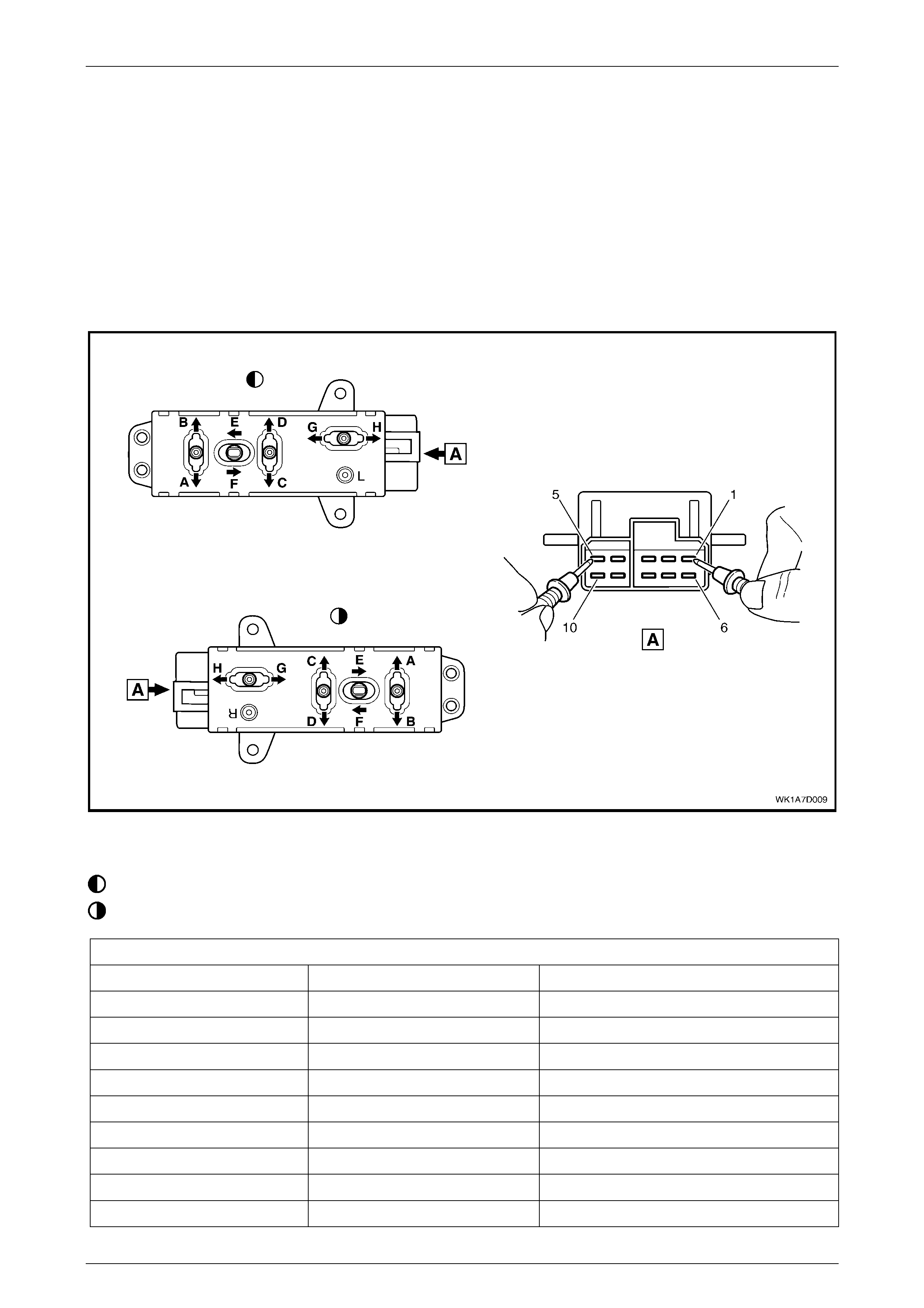
Seat Assemblies Page 1A7–213
Page 1A7–213
5.5 Eight-way Seat Adjustment Switch Test
The switch is located on the outer side of the seat, attached to the inner side of the front seat outer side cover.
Test
1 Remove the eight-way seat adjustment switch, refer to 4.4 Front Seat Outer Side Cover Assembly.
2 Place the switch in the positions as detailed in the chart in this Section. Place the probes of the ohmmeter onto the
terminals listed and take the reading. Compare the reading to the chart.
3 If the switch fails any part of the test, replace the switch assembly with a serviceable item.
4 Install the eight-way seat adjustment switch, refer to 4.4 Front Seat Outer Side Cover Assembly.
Figure 1A7 – 161
Legend
Left-hand Switch
Right-hand Switc h
Eight-way Seat Adjustment Switch
Switch Posi tion Switch Terminals Indication if Switch is Serviceable
Position A 10 and 5 Continuity
Position B 7 and 5 Continuity
Position C 9 and 5 Continuity
Position D 8 and 5 Continuity
Position E 6 and 5 Continuity
Position F 3 and 5 Continuity
Position G 2 and 5 Continuity
Position H 4 and 5 Continuity
Switch in the neutral position 1 and either 2, 3, 4, 6, 7, 8, 9 or 10 Continuity

Seat Assemblies Page 1A7–214
Page 1A7–214
6 Diagnostics – Front Seat
Memory and Rear View Mirror,
Level 5
6.1 Prerequisites
Safety Requirements
When operating the seat as part of any Steps
in the diagnosis charts, ensure that fingers
and limbs are clea r of moving parts.
Equipment
The followi ng equipment is required to diagnose the seats:
1 An unpowered test lamp with a current draw of less than 3 A.
2 A digital multimeter with a minimum impedance of 10 MΩ.
Testing Procedures
The following points must be adhered to when performing diagnostic testing on components:
1 Care must be taken when using testing equipment to diagnose wiring harness connectors. It is preferred that the
technician backprobe the connector to avoid damage to terminals.
2 When tests are required on connector terminals, use the adapters in the connector adapter kit (tool No. KM–609) to
prevent damage to the terminals.
3 Unless the multimeter being us ed has an auto-ranging function, ensure that the correct range is selected.
4 When backprobing connectors, ensure the test lamp ground lead is connected to a suitable ground point on the
vehicle. Ensure this ground point is not part of the circuit being tested.
NOTE
Perform the Steps in the diagnosis charts in the
order shown. If the required nominal value or
result is not achieved at any stage, the problem
must be rectified before proceeding.

Seat Assemblies Page 1A7–215
Page 1A7–215
6.2 System Self Diagnosis
The seat memory module can self-diagnose the driver's seat and the external rear-view mirrors. When a fault or failure is
detected, the seat memory module sets a diagnostic trouble code (DTC) that represents the fault or failure. A fault or
failure that sets a DTC may leave the seat and/or external rear-view mirrors partially or totally inoperative. If the seat
memory module detects a fault, the LED located next to the mirror dip / memory store (M) button on the memory position
switch assembly, illuminates constantly during that ignition cycle.
Current DTCs are stored by the seat memory module. When the fault conditions are no longer met, the DTC becomes a
Histo r y DTC.
Current DTCs
When Current DTCs are detected, they are stored by the seat memory module during the current ignition cycle. Current
DTCs are set or cleared based on the condition of the seat memory module during ignition ON or continuous monitoring
of the current ignitio n cycle.
NOTE
A Current DTC is identified on the TECH 2
display by the word 'Current' between the DTC
number and the DTC description. The word
'History' between the DTC number and the DTC
description indicates that the DTC displayed is a
Histo r y DTC.
Current DTCs are reset to History DTCs upon the next diagnostic test sequence that the fault conditions are not met.
Current DTCs can be cleared (changed to history DTC) by removing the fault conditions.
TECH 2 is unable to clear current DTCs if the fault conditions still exist; TECH 2 will display 'Clear DTC Information
Failed'.
DTCs stored in the seat memory module can only be displayed and/or cleared using the TECH 2 diagnostic scan tool.
The TECH 2 communicates with seat memory module serial data using the Serial Data Link Connector (DLC) which is
attached to the instrument panel lower trim retainer, refer to 6.3 TECH 2 Diagnostics.
History DTCs
History DTCs are set upon the clearing of a current DTC fault condition. History DTCs are maintained by the seat
memory module over multiple ignition cycles. The seat memory module can only clear history DTCs from its memory by
a CLEAR DTCS serial data message from TECH 2.
Clearin g DTCs
After any system fault has been rectified, use the TECH 2 CLEAR DTCS selection to erase any fault codes stored in the
seat memory module's memory, refer to 6.4 TECH 2 Test Modes and Displays for Diagnosis.
After DTCs have been cleared, verify proper
system operation and absence of any fault
codes. If TECH 2 displays CLEAR DTC
INFORMATION FAILED after attempting to
clear DTCs, the fault condition still exists.

Seat Assemblies Page 1A7–216
Page 1A7–216
6.3 TECH 2 Diagnostics
TECH 2, with the appropriate software, cables and
adapters, when connected to the Serial Data Link Connector
(DLC) can read seat and exterior rear-view mirror serial
data. The DLC is attached to the instrument panel trim
retainer beneath the steering wheel.
1 DLC
2 DLC Adapter
3 DLC Cable
4 TECH 2
For additional general information on connecting and
operating TECH 2, refer to Section 0C TECH 2.
Figure 1A7 – 162
Test Modes
TECH 2 has five test modes for diagnosing the driver's seat
and the external rear-view mirrors.
Mode F0: Diagnostic Trouble Codes
If F0: Diagnostic Trouble Codes is selected, a selection list
is displayed which contains:
1 F0: Read DTC Information – Once this mode is
selected, both current and history Diagnostic Trouble
Codes (DTCs) stored in the seat memory module's
memory may be displayed.
2 F1: Clear DTC Information – Once this mode is
selected, DTCs stored in the seat memory module's
memory may be cleared.
Figure 1A7 – 163
Mode F1: Diagnostic Data Display
If F1: Diagnostic Data Display is selected, a selection list is displayed which contains:
1 F0: Inputs and Outputs − Once this mode is selected, a list of system components and their inputs, outputs and
their status is display ed .
2 F1: Memory − Once this mode is selected, a list of each memory position and the position of each of the seat axes
is displayed.
3 F2: System Identification – Once this is selected, details including serial number of the seat memory module are
displayed.
Mode F2: Snapshot
In this test mode, the TECH 2 captures seat memory module data before and after a forced manual trigger.
Mode F3: Miscellaneous Tests
In this test mode, the TECH 2 displays a list of eight tests that can be utilised to diagnose the driver's seat and the
external rear-view mirrors, refer to 6.4 TECH 2 Test Modes and Displays for Diagnosis for further information.
Mode F4: Additional Functions
In this test mode, TECH 2 allows the technician to reset the seat, thus clearing all memory positions, refer to
6.4 TECH 2 Test Modes and Displays for Diagnosis for further information.
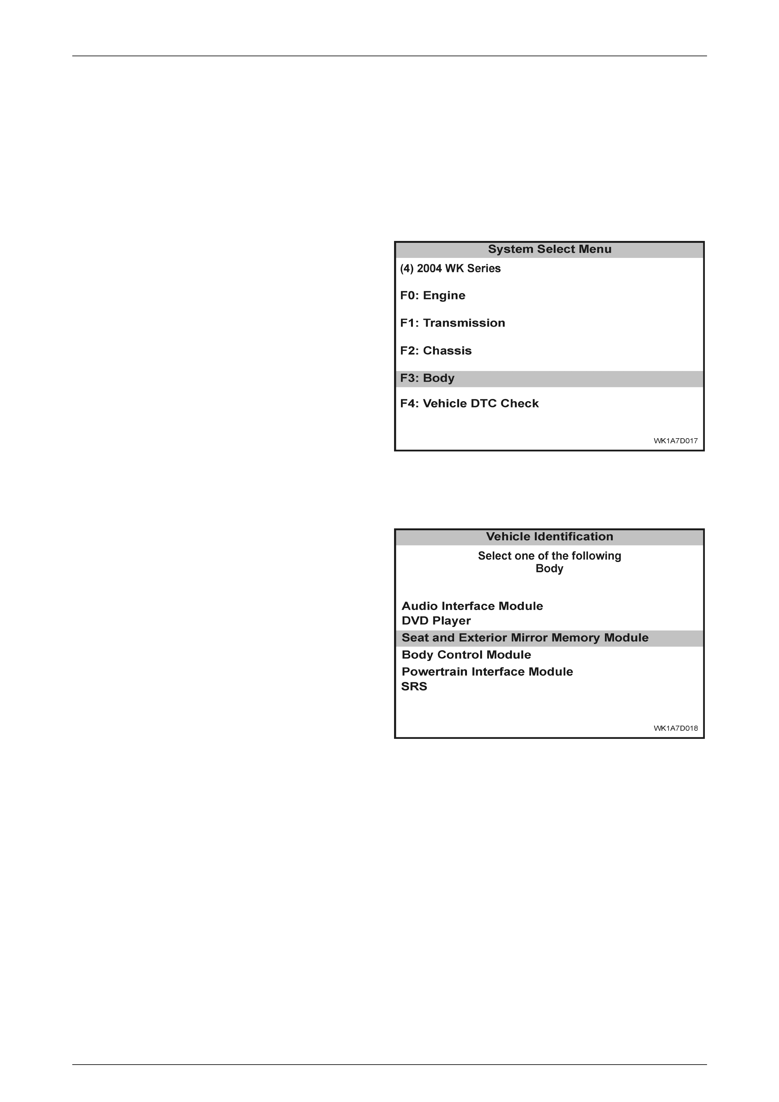
Seat Assemblies Page 1A7–217
Page 1A7–217
6.4 TECH 2 Test Modes and Displays for
Diagnosis
A prerequisite to this diagnostic Section is for the user to be familiar with the proper use of TECH 2. The following pages
illustrate only the major TECH 2 screen displays and provide a brief explanation of their function for diagnosing the
driver's seat and the external rear-view mirrors. If additional information is required on the operation of TECH 2,
reference should be made to either Section 0C TECH 2 or the TECH 2 User's Guide.
System Select Menu
With the TECH 2 connected to the DLC, and
F0: DIAGNOSTICS selected from the Main Menu, the
correct Model Year and Vehicle Type must be selected for
access to the System Select Menu.
Select F3: BODY.
This mode contains all functions to test, diagnose, monitor
and program the vehicle's body systems including the
driver's seat and the external rear-view mirrors.
Figure 1A7 – 164
Body Application Menu
Once F3: BODY has been selected from the System Select
Menu, Seat and Exterior Mirror Memory Module can be
selected.
Select SEAT AND EXTERIOR MIRROR MEMORY
MODULE.
When SEAT AND EXTERIOR MIRROR MEMORY
MODULE is selected, the following two SYSTEM
IDENTIFICATION screens will appear, which require action.
Figure 1A7 – 165
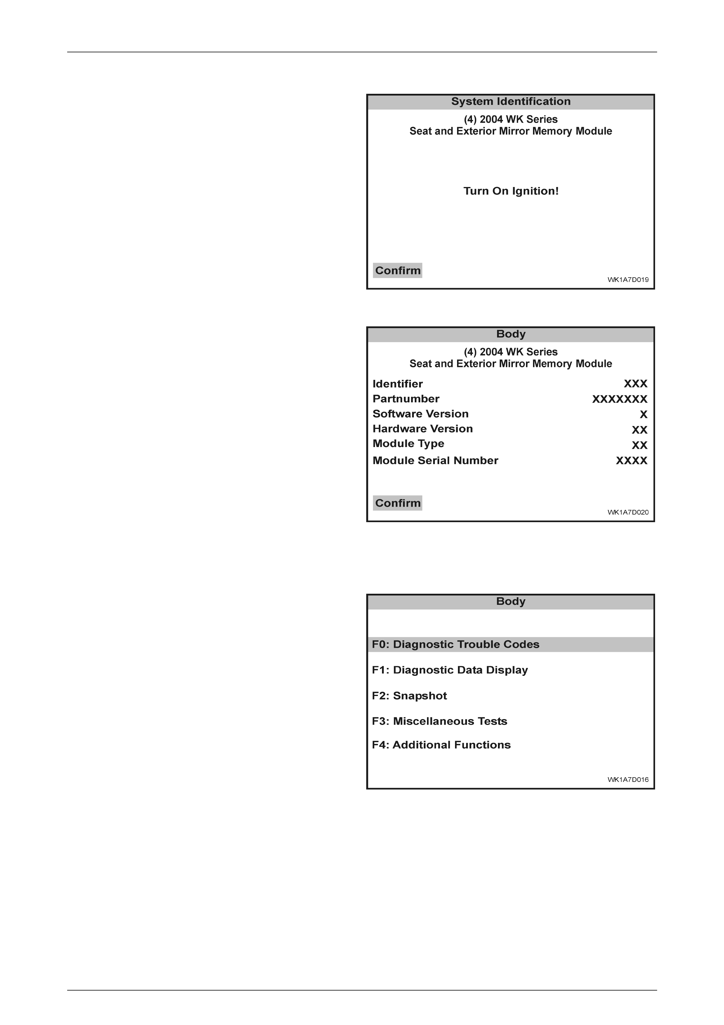
Seat Assemblies Page 1A7–218
Page 1A7–218
System Identification
Turn the ignition to the ON position with the engine not
running (as requested) and press the CONFIRM soft key to
continue.
Figure 1A7 – 166
The System Identification Screen will then display
information pertaining to the type of seat memory module
fitted, serial number, date of manufacture and other ancillary
information. Press the CONFIRM soft key to continue to the
Application men u.
Always refer to the latest General Motors spare parts
information for the correct part number.
Figure 1A7 – 167
A pplication Menu
The following functions will now be available:
• F0: DIAGNOSTIC TROUBLE CODES
• F1: DIAGNOSTIC DATA DISPLAY
• F2: SNAPSHOT
• F3: MISCELLANEOUS TESTS
• F4: ADDITIONAL FUNCTIONS
Figure 1A7 – 168
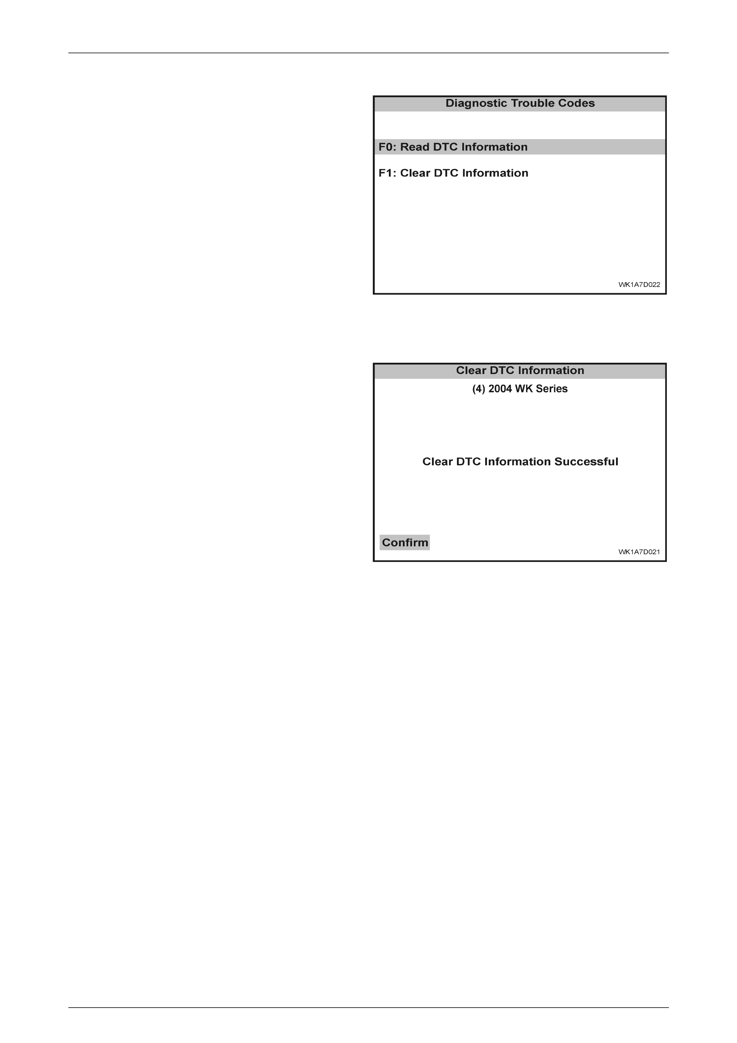
Seat Assemblies Page 1A7–219
Page 1A7–219
F0: Diagnostic Trouble Codes
If F0: DIAGNOSTIC TROUBLE CODES is selected from the
Application menu, a selection list is displayed which
contains:
F0: Read DTC Information
If this mode is selected, a listing of all (i f any) DTCs that
have been set by the seat memory module will be displayed.
Information displayed with the DTC number/s that have
been set, is a short description of what the DTC is, and
whether it is a current (fault present) or hi story (stored, but
not necessarily on this ignition cycle) DTC. Refer to
Diagnostic Trouble Codes in this Section for the full listing of
driver's seat and the external rear-view mirrors DTCs with
the fault identified.
NOTE
If any DTCs are set, reference should be made
to the relevant diagnostic charts in this Section.
Figure 1A7 – 169
F1: Clear DTC Information
DTCs can be cleared in this mode by selecting F1: CLEAR
DTC INFORMATION, pressing the ENTER button on
TECH 2 and confirming the action as instructed by TECH 2.
If DTC condition is present, TECH 2 will be unable to clear
the DTC and will display CLEAR DTC INFORMATION
FAILED.
Figure 1A7 – 170

Seat Assemblies Page 1A7–220
Page 1A7–220
Diagnostic Trouble Codes
The following table sets out all the possible diagnostic trouble codes as indicated by TECH 2.
DTC Code Location Fault
1 Eight-way seat adjust ment sw itch Front vertical up switch stu ck
2 Eight-way seat adjustm ent switch Front vertical down switch stuck
3 Eight-way seat adjustment switch Rear vertical up switch stuck
4 Eight-way seat adjustment switch Rear vertical down switch stuck
5 Eight-way seat adjust ment sw itch Horizontal forw ard sw itch stu c k
6 Eight-way seat adjust ment sw itch Horizontal ba ck switch stuc k
7 Eight-way seat adjustment switch Recline up switch stuck
8 Eight-way seat adjus tment switch Recline down switch stuck
9 Memory position switch assembly Memory button 1 stuck
10 Memory position switch assembly Memory button 2 stuck
11 Memory position switch assembly Memory button 3 stuck
12 Memory position switch assembly Mirror dip button stuck
13 Seat memory module No serial data
14 Exterior rear-view mi rror circuit No exterior mirror communication
15 Seat front lift motor potentiometer Front vertical position sensor fault
16 Seat rear lift motor potentiometer Rear vertical position sensor fault
17 Seat fore/aft movement motor potentiometer Horizontal position sensor fault
18 Seat-back recline motor potentiometer Recline position sensor fault
19 Seat memory module ECU malfunction
F1: Diagnostic Data Display
When F1: DIAGNOSTIC DATA DISPLAY is selected, three sub-headings are displayed by TECH 2.
F0: Inputs and Outputs
F0: INPUTS AND OUTPUTS displays a list of data streams for various driver's seat and external rear-view mirror
components and their current status. The table in this Section lists all the data streams with a description.
Data Stream /
Screen Display Description
Memory 1 Button Displays the state of button 1 on the memory position switch.
If button 1 on the memory position switch assembly is stuck in the depressed position for
more than 8 seconds, DTC 9 will be set.
• inactive / active
Memory 2 Button Displays the state of button 2 on the memory position switch.
If button 2 on the memory position switch assembly is stuck in the depressed position for
more than 8 seconds, DTC 10 will set.
• inactive / active

Seat Assemblies Page 1A7–221
Page 1A7–221
Data Stream /
Screen Display Description
Memory 3 Button Displays the state of button 3 on the memory position switch.
If button 3 on the memory position switch assembly is stuck in the depressed position for
more than 8 seconds, DTC 11 will set.
• inactive / active
Mirror DIP Button Displays the state of the mirror dip / memory store (M) button on the memory position
switch.
If the mirror DIP / memory store (M) button on the memory position switch assembly is
stuck in the depressed position for more than 8 seconds, DTC 12 will set.
• inactive / active
Front Vertical Switch Displays the state of the front lift switch on the seat adjustment switch.
If the front vertical switch is stuck in the UP position for more than 8 seconds, DTC 1 will
set.
If the front vertical switch is stuck in the DOWN position for more than 8 seconds, DTC 2
will set.
• inactive / up / down
Rear Vertical Switch Displays the state of the rear lift switch on the seat adjustment switch.
If the rear vertical switch is stuck in the UP position for more than 8 seconds, DTC 3 will set.
If the front vertical switch is stuck in the DOWN position for more than 8 seconds, DTC 4
will set.
• inactive / up / down
Horizontal Switch Displays the state of the horizontal switch on the seat adjustment switch.
If the horizontal switch is stuck in the FORWARD position for more than 8 seconds, DTC 5
will set.
If the horizontal switch is stuck in the AFT position for more than 8 seconds, DTC 6 will set.
• inactive / forward / backward
Recline Switch Displays the state of the recline switch on the seat adjustment switch.
If the recline switch is stuck in the FORWARD position for more than 8 seconds, DTC 7 will
set.
If the recline switch is stuck in the AFT position for more than 8 seconds, DTC 8 will set.
• inactive / forward / backward
Front Vertical Position
Sensor Displays whether the front lift motor potentiometer is connected.
• connect ed / not connec ted
Front Vertical Position
Sensor Signal Displays the voltage across the front lift motor potentiometer. The voltage will range from
1.5 V to 4.2 V depending on the vertical position of the front of the seat.
• 1.5 – 4.2 volts
Front Vertical Position
Sensor Displays the current position of the front lift motor potentiometer as a value in Steps. The
Steps will range from 0 to 255 and are calculated by taking the voltage across the
potentiometer and putting that value through a mathematical algorithm.
• 0 – 255

Seat Assemblies Page 1A7–222
Page 1A7–222
Data Stream /
Screen Display Description
Front Vertical Position
Maximum Limit Displays the maximum limit of travel up in Steps. This value depends on the calibration of
the seat.
This value should be high but never reach 255 Steps. If the value displayed is 255, the seat
has not been calibrated. Refer to 4.3 Front Seat Assembly to calibrate the seat.
• 0 – 255
Front Vertical Position
Minimum Limit Displays the minimum limit of travel down in Steps. This value depends on the calibration of
the seat.
This value should be low but never reach 0 Steps. If the value displayed is 0, the seat has
not been calibrated. Refer to 4.3 Front Seat Assembly to calibrate the seat.
• 0 – 255
Rear Vertical Posi tion
Sensor Displays whether the rear lift motor potentiometer is connected.
• connect ed / not connec ted
Rear Vertical Posi tion
Sensor Signal Displays the voltage across the rear lift motor potentiometer. The voltage will range from
1.5 V to 4.2 V depending on the vertical position of the rear of the seat.
• 1.5 – 4.2 volts
Rear Vertical Posi tion
Sensor Displays the current position of the rear lift motor potentiometer as a value in Steps. The
Steps will range from 0 to 255 and are calculated by taking the voltage across the
potentiometer and putting that value through a mathematical algorithm.
• 0 – 255
Rear Vertical Posi tion
Maximum Limit Displays the maximum limit of travel up in Steps. This value depends on the calibration of
the seat.
This value should be high but never reach 255 Steps. If the value displayed is 255, the seat
has not been calibrated. Refer to 4.3 Front Seat Assembly to calibrate the seat.
• 0 – 255
Rear Vertical Posi tion
Minimum Limit Displays the minimum limit of travel down in Steps. This value depends on the calibration of
the seat.
This value should be low but never reach 0 Steps. If the value displayed is 0, the seat has
not been calibrated. Refer to 4.3 Front Seat Assembly to calibrate the seat.
• 0 – 255
Horizontal Position Sens or Displays whether the fore/aft movement motor potentiometer is connected.
• connect ed / not connec ted
Horizontal Position Sensor
Signal Displays the voltage across the fore/aft movement motor potentiometer. The voltage will
range from 1.5 V to 4.2 V depending on the horizontal position of the seat.
• 1.5 – 4.2 volts
Horizontal Position Sens or Displays the current position of the fore/aft movement motor potentiometer as a value in
Steps. The Steps will range from 0 to 255 and are calculated by taking the voltage across
the potentiometer and putting that value through a mathematical algorithm.
• 0 – 255
Horizontal Position
Maximum Limit Displays the maximum limit of travel forward in Steps. This value depends on the calibration
of the seat.
This value should be high but never reach 255 Steps. If the value displayed is 255, the seat
has not been calibrated. Refer to 4.3 Front Seat Assembly to calibrate the seat.
• 0 – 255

Seat Assemblies Page 1A7–223
Page 1A7–223
Data Stream /
Screen Display Description
Horizontal Position
Minimum Limit Displays the minimum limit of travel aft in Steps. This value depends on the calibration of
the seat.
This value should be low but never reach 0 Steps. If the value displayed is 0, the seat has
not been calibrated. Refer to 4.3 Front Seat Assembly to calibrate the seat.
• 0 – 255
Recline Position Sensor Displays whether the seat-back recline motor potentiometer is connected.
• connect ed / not connec ted
Recline Position Sensor
Signal Displays the voltage across the seat-back recline motor potentiometer. The voltage will
range from 1.5 V to 4.2 V depending on the recline position of the seat.
• 1.5 – 4.2 volts
Recline Position Sensor Displays the current position of the seat-back recline motor potentiometer as a value in
Steps. The Steps will range from 0 to 255 and are calculated by taking the voltage across
the potentiometer and putting that value through a mathematical algorithm.
• 0 – 255
Recline Position Maximum
Limit Displays the maximum limit of travel forward in Steps. This value depends on the calibration
of the seat.
This value should be high but never reac h 255 Steps. If the value displayed is 255, the seat
has not been calibrated. Refer to 4.3 Front Seat Assembly to calibrate the seat.
• 0 – 255
Recline Position Minimum
Limit Displays the minimum limit of travel aft in Steps. This value depends on the calibration of
the seat.
This value should be low but never reach 0 Steps. If the value displayed is 0, the seat has
not been calibrated. Refer to 4.3 Front Seat Assembly to calibrate the seat.
• 0 – 255
Button Pack
Communication Displays whether there is serial data communication with the mirror control switch, right-
hand or left-hand rear-view mirrors. If there is comm unication with at least one of these
components, TECH 2 will display OKAY. If there is no communications with all of the
components, TECH 2 will display NOT OKAY.
If there are no serial data communications, a DTC 14 will set.
• ok / not ok
Right Exterior Mirror
Communication Displays whether TECH 2 can communicate with the right-hand exterior rear-view mirror.
If there is not serial data communications with the right-hand exterior rear-view mirror, a
DTC 14 will set.
• ok / not ok
Left Exterior Mirror
Communication Displays whether TECH 2 can communicate with the left-hand exterior rear-view mirror.
If there is not serial data communications with the left-hand exterior rear-view mirror, a DTC
14 will set.
• ok / not ok
Right Exterior Mirror Switch Displays the status of the mirror control switch, when the rock er switch is selected to
RIGHT.
• up / down / left / right / inactive
Left Exterior Mirror Switch Displays the status of the mirror control switch, when the rocker switch is selected to LEFT.
• up / down / left / right / inactive

Seat Assemblies Page 1A7–224
Page 1A7–224
Data Stream /
Screen Display Description
Memory Recall Position In
Use Displays the status of the current memory recall of the seat assembly.
• memory button 1 / memory button 2 / memory button 3 / priority 1 / priority 2 / no
active me mory
Current Priority Displays what is the current priority that has been set when the vehicle is unlocked with
either priority key 1 or 2.
• priority 1 / priority 2 / no active memory
Able To Recall Displays whether the seat assembly has the ability to recall a memory position.
• yes / no
Start Wait Active Only when there has been a cold-start reset will TECH 2 display NO. A cold-start reset will
occur when module detects too much electromagnetic interference (EMI) in the system. If
the START WAIT ACTIVE displays NO, the system will still be operational.
• yes / no
Able To Move When the seat is requested to move, the seat memory module monitors the amount of
Steps that a potentiometer has taken during that movement. If the potentiometer does not
move more than 3 Steps in 1 second, ABLE TO MOVE will be NO. This inability to move at
all or quickly enough may be due to a physical restriction in that movement, or the battery
not having enough charge to power the particular motor adequately.
• yes / no
Ignition Switch Displays the status of the ignition switch.
• on / off / accessory
Demist Request Displays the status of the rear demist system. This will be YES when the rear demist button
is pressed.
• yes / no
Reverse Gear Di splays whether the vehicle is in reverse gear.
• inactive / active
PRNDL Position Displays the position of the transmission selector.
• P / R / N / D / 3 / 2 / 1
F1: Memory
F1: MEMORY displays all the five memory settings available. Within each of the memory settings the position of the seat
is displayed (in Steps) and whether the mirror dip function is enable d.
Data Stream /
Screen Display Description
Memory 1 Mirror Dip Status Displays whether the mirror dip function is enabled for Memory 1.
• enabled / disabled
Memory 1 Front Vertic al
Position Displays the seat front vertical position (in Steps) that has been stored in Memory 1.
• 0 – 255
Memory 1 Rear Vertical
Position Displays the seat rear vertical position (in Steps) that has been stored in Memory 1.
• 0 – 255
Memory 1 Horizontal
Position Displays th e seat horizontal position (in Steps) that has been stored in Memory 1.
• 0 – 255
Memory 1 Recline Position Displays the seat-back recline position (in Steps) that has been stored in Memory 1.
• 0 – 255

Seat Assemblies Page 1A7–225
Page 1A7–225
Data Stream /
Screen Display Description
Memory 2 Mirror Dip Status Displays whether the mirror dip function is enabled for Memory 2.
• enabled / disabled
Memory 2 Front Vertic al
Position Displays the seat front vertical position (in Steps) that has been stored in Memory 2.
• 0 – 255
Memory 2 Rear Vertical
Position Displays the seat rear vertical position (in Steps) that has been stored in Memory 2.
• 0 – 255
Memory 2 Horizontal
Position Displays th e seat horizontal position (in Steps) that has been st ored in Memory 2.
• 0 – 255
Memory 2 Recline Position Displays the seat-back recline position (in Steps) that has been stored in Memory 2.
• 0 – 255
Memory 3 Mirror Dip Status Displays whether the mirror dip function is enabled for Memory 3.
• enabled / disabled
Memory 3 Front Vertic al
Position Displays the seat front vertical position (in Steps) that has been stored in Memory 3.
• 0 – 255
Memory 3 Rear Vertical
Position Displays the seat rear vertical position (in Steps) that has been stored in Memory 3.
• 0 – 255
Memory 3 Horizontal
Position Displays th e seat horizontal position (in Steps) that has been stored in Memory 3.
• 0 – 255
Memory 3 Recline Position Displays the seat-back recline position (in Steps) that has been stored in Memory 3.
• 0 – 255
Priority 1 Mirror Dip Status Displays whether the mirror dip function is enabled for Priority 1.
• enabled / disabled
Priority 1 Front Vertical
Position Displays the seat front vertical position (in Steps) that has been stored in Priority 1.
• 0 – 255
Priority 1 Rear Vertical
Position Displays the seat rear vertical position (in Steps) that has been stored in Priority 1.
• 0 – 255
Priority 1 Horizontal
Position Displays th e seat horizontal position (in Steps) that has been stored in Priority 1.
• 0 – 255
Priority 1 Recline Position Displays the seat-back recline position (in Steps) that has been stored in Priority 1.
• 0 – 255
Priority 2 Mirror Dip Status Displays whether the mirror dip function is enabled for Priority 2.
• enabled / disabled
Priority 2 Front Vertical
Position Displays the seat front vertical position (in Steps) that has been stored in Priority 2.
• 0 – 255
Priority 2 Rear Vertical
Position Displays the seat rear vertical position (in Steps) that has been stored in Priority 2.
• 0 – 255

Seat Assemblies Page 1A7–226
Page 1A7–226
Data Stream /
Screen Display Description
Priority 2 Horizontal
Position Displays th e seat horizontal position (in Steps) that has been stored in Priority 2.
• 0 – 255
Priority 2 Recline Position Displays the seat-back recline position (in Steps) that has been stored in Priority 2.
• 0 – 255
F2: System Identification
F2: SYSTEM IDENTIFICATION displays the specifications of the seat memory module, refer to System Identification
within this Section.
F2: Snapshot
In this mode, TECH 2 captures seat memory module data before and after a forced manual trigger.
F3: Miscellaneous Tests
In this mode, a list of tests are displayed that can be used to control certain functions of the driver's seat and the exterior
rear-view mirrors.
F0: Chime
When this test is selected, menu keys are available. To activate the chime function of the seat memory module, press
the ON key. The chime will then sound continuously. To turn off the chime, press the OFF key. To return to
F3: MISCELLANEOUS TESTS menu, press the QUIT key.
In this test, the input and output data is also displayed, refer to F0: Inpu ts and Out put s in this Section.
F1: LED
When this test is selected, menu keys are available. To activate the LED functi on of the seat memory module, press the
FLASH key. The LED will flash. To return to F3: MISCELLANEOUS TESTS menu, press the QUIT key.
In this test, the input and output data is also displayed, refer to F0: Inpu ts and Out put s in this Section.
F2: Right Exterior Mirror
When this test is selected, the arrow keys on TECH 2 can be used to drive the right-hand exterior mirror in all four
directions. During this test the data stream for the right-hand exterior mirror will be displayed. The data stream will
change from OFF to the direction pressed.
F3: Left Exterior Mirror
When this test is selected, the arrow keys on TECH 2 can be used to drive the left-hand exterior mirror in all four
directions. During this test the data stream for the left-hand exterior mirror will be displayed. The data stream will change
from OFF to the direction pressed.
F4: Front Vertical Motor
When this test is selected, menu keys are available. To drive the front lift motor up, press the UP key and alternatively to
move the front lift motor down, press the DOWN key.
F5: Rear vertical Mirror
When this test is selected, menu keys are available. To drive the rear lift motor up, press the UP key and alternatively to
move the rear lift motor down, press the DOWN key.
F6: Horizontal Motor
When this test is selected, menu keys are available. To drive the seat fore/aft movement motor forward, press the
FORWARD key and alternatively to move the seat fore/aft movement motor aft, press the BACK key.

Seat Assemblies Page 1A7–227
Page 1A7–227
F7: Recline Motor
When this test is selected, menu keys are available. To drive the seat-back recline motor forward, press the FORWARD
key and alternatively to move the seat-back recline motor aft, press the BACK key.
F4: Addi ti onal Functions
F0: Module Reset
This function clears all the preset memories including any priority key that the seat memory module has stored.
When this function is selected, menu keys are available. TECH 2 will prompt with the message 'Do you Really Want To
Reset'. To reset the module, press the YES key. If the technician does not want to reset the module, press the NO key
and to return the F4: ADDITIONAL FUNCTIONS menu.

Seat Assemblies Page 1A7–228
Page 1A7–228
6.5 Preliminary System Diagnosis
Prior to starting any diagnosis, the technician should be familiar with the driver's seat and the external rear-view
mirror components and operation. For a description of the components and the system operation, refer to
1 General Information
When investigating any complaint of a problem or malfunction, always begin diagnosis with a circuit check, refer to
6.8 Electrical Diagnosis – Memory Seat, Initial Check for a seat fault, or 6.10 Electrical Diagnosis – Rear-view Mirrors,
Initial Check for an exterior rear-view mirror fault.
The diagnostic circuit check ensures that the driver's seat and the external rear-view mirrors are communicating on the
serial data line as well as assisting to identify the problem and to ascertain the appropriate diagnostic chart in this
Section.

Seat Assemblies Page 1A7–229
Page 1A7–229
6.6 Diagnostic Charts
Introduction
The followi ng diagnostic charts are designed to provide fast and efficient fault location and remedy. The diagnostic charts
include a chart, pertinen t information, circuit diagra ms, and where necessary , the steps are ex plained by the
corresponding numbered paragraphs.
When performing wiring checks as directed to by the diagnostic charts, rather than probe pins and connectors with
incorrect sized multimeter connections, use the adapters contained in connector test adapter kit Tool No. KM-609 and
test lead set Tool No. KM609-20. This will prevent any possibility of spreading or damaging wiring harness pins and later
on causing a system intermittent failure.

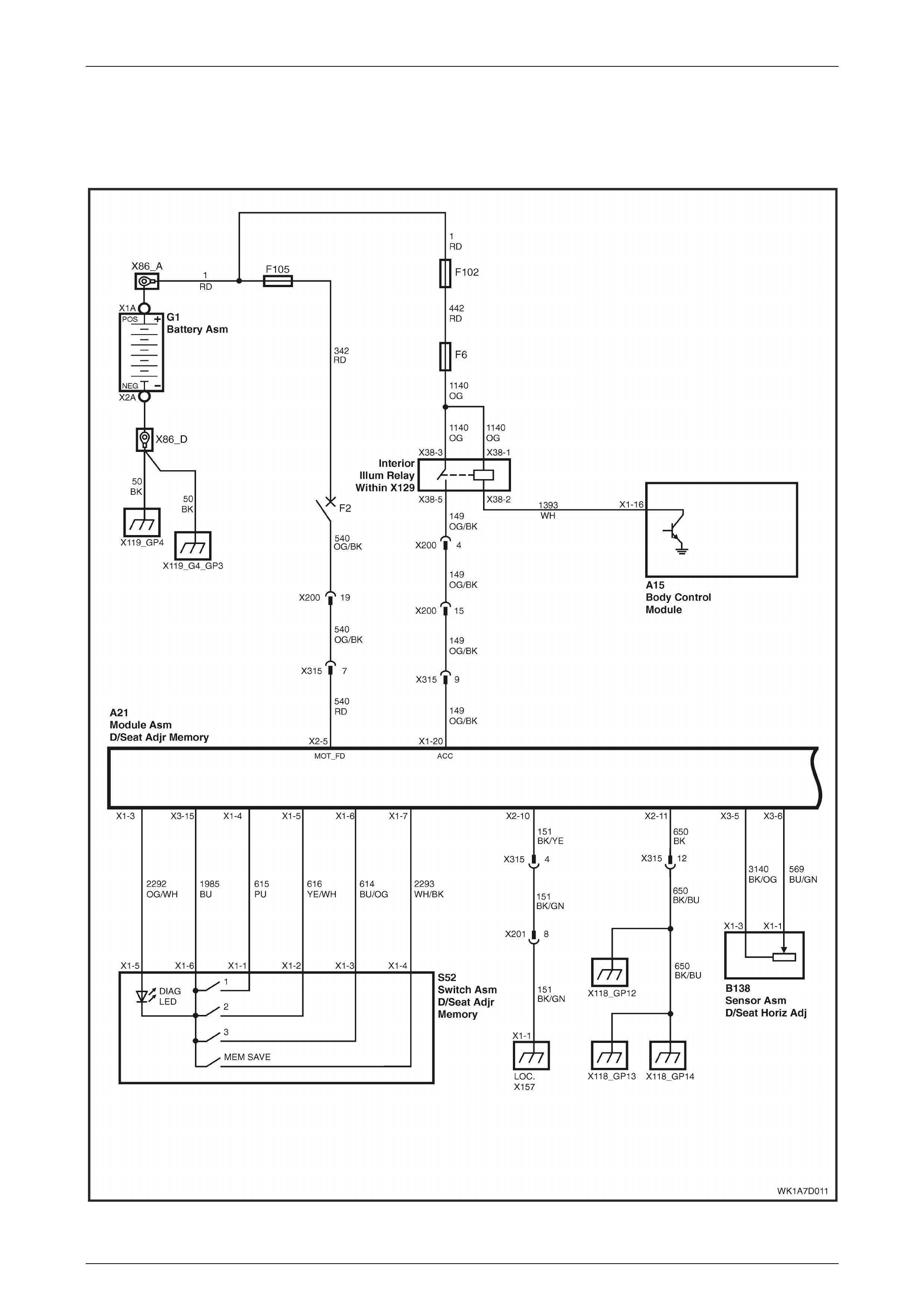
Seat Assemblies Page 1A7–231
Page 1A7–231
6.8 Electrical Diagnosis – Memory Seat
Wiri ng Diagr am – RHD
Figure 1A7 – 171

Seat Assemblies Page 1A7–232
Page 1A7–232
Figure 1A7 – 172
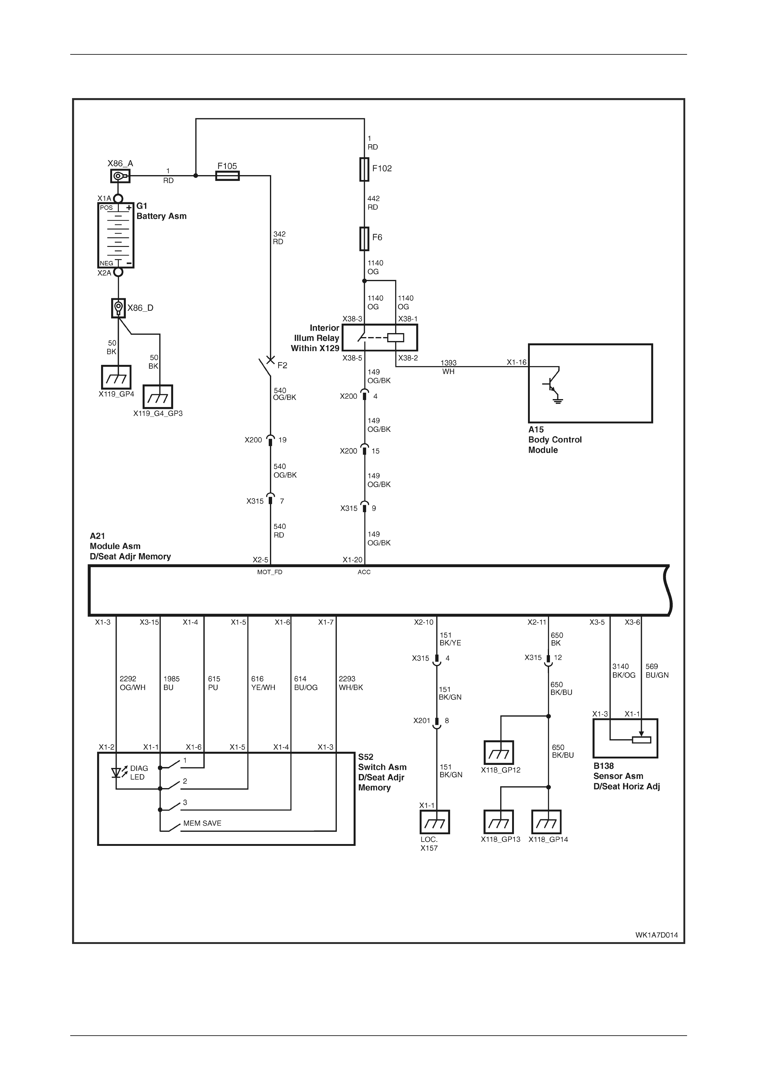
Seat Assemblies Page 1A7–233
Page 1A7–233
Wiring Diagram – LHD
Figure 1A7 – 173
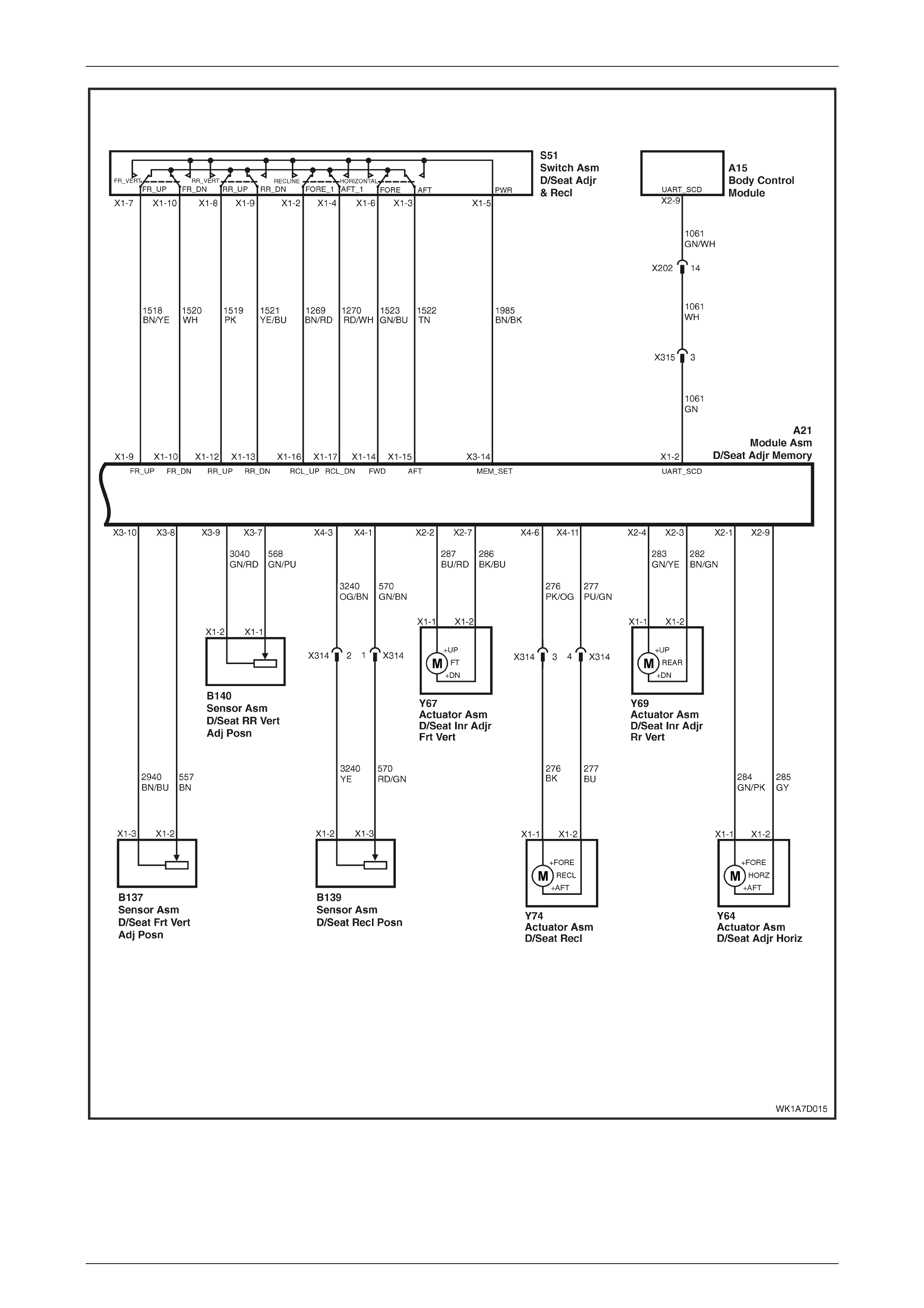
Seat Assemblies Page 1A7–234
Page 1A7–234
Figure 1A7 – 174
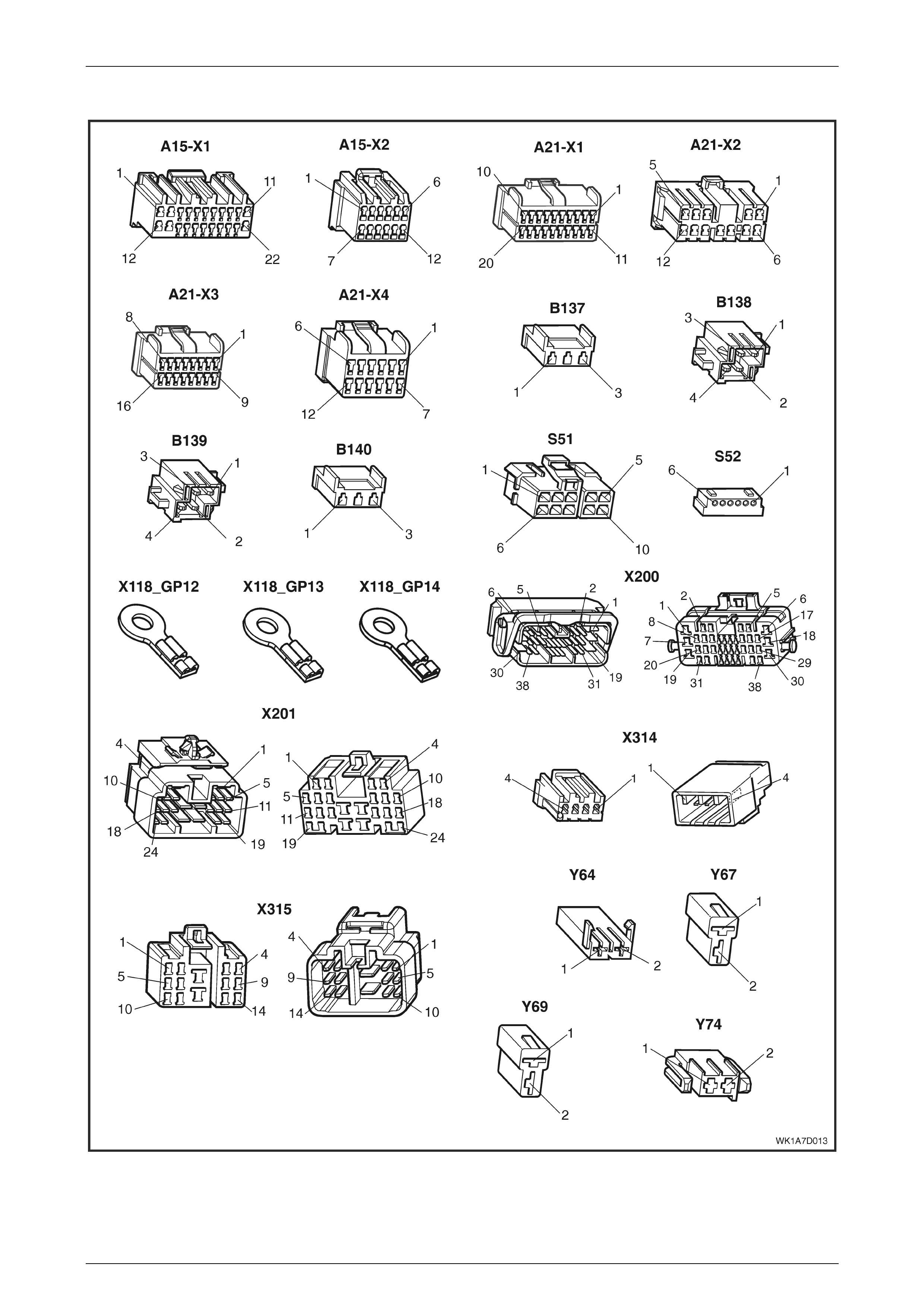
Seat Assemblies Page 1A7–235
Page 1A7–235
Connector Chart
Figure 1A7 – 175

Seat Assemblies Page 1A7–236
Page 1A7–236
Initial Check
Circuit Description
The driver's seat and exterior rear-view mirrors can be diagnosed through TECH 2. This chart tests each function of the
seat for correct operation.
Test Description
1 If TECH 2 cannot access the System Identification menu there is a problem with the power, serial data
communic atio ns and groun d ci rcuit s to the memory modul e.
2 Checks if there are any current DTCs.
3-10 Checks that the seat adjustment switch is serviceable. Also checks that the associated motor circuits are
serviceable.
11 Using TECH 2, checks that the memory position switch assembly is operational.
12 Checks that the front lift motor potentiometer is connected.
13 Checks that the front lift motor potentiometer's voltage is within the acceptable range.
14 Checks that the front lift motor potentiometer (in Steps) has an acceptable maximum, minimum value and current
seat position is within that range.
15 Checks that the rear lift motor potentiometer is connected.
16 Checks that the rear lift motor potentiometer's voltage is within the acceptable range.
17 Checks that the rear lift motor potentiometer (in Steps) has an acceptable maximum, minimum value and current
seat position is within that range.
18 Checks that the horizontal motor potentiometer is connected.
19 Checks that the horizontal motor potentiometer's voltage is within the acceptable range.
20 Checks that the horizontal motor potentiometer (in Steps) has an acceptable maximum, minimum value and current
seat position is within that range.
21 Checks that the recline motor potentiometer is connected.
22 Checks that the recline motor potentiometer's voltage is within the acceptable range.
23 Checks that the recline motor potentiometer (in Steps) has an acceptable maximum, minimum value and current
seat position is within that range.
24 Checks that the seat memory module stores a different seat position in each of the three memory buttons. Checks
that when each of the memory buttons are pressed, the seat moves to the stored position and TECH 2 displays the
correct information.
25 Checks that the seat recalls a priority key memory position.
Step Action Yes No
1 1 Connect TECH 2 to the DLC.
2 Select BODY / SEAT AND EXTERIOR MIRROR MEMORY
MODULE.
3 Turn the ignition on when prompted.
Is the Seat and Exterior Mirror Module System Identific ation
sp ecif ications displayed?
Go to Step 2.
Refer to
No Serial Data
Communications to
the Seat Memory
Module.
2 1 Select BODY / SEAT AND EXTERIOR MIRROR MEMORY
MODULE / DIAGNOSTIC TROUBLE CODES / READ DTC
INFORMATION.
Are there any DTCs set?
Refer to the relevant
DTC diagnostic
chart in this Section. Go to Step 3.

Seat Assemblies Page 1A7–237
Page 1A7–237
Step Action Yes No
3 1 With TECH 2 connected to the DLC, select BODY / SEAT AND
EXTERIOR MIRROR MEMORY MODULE / DIAGNOSTIC
DATA DISPLAY / INPUTS AND OUTPUTS.
2 Scroll to FRONT VERTICAL SWITCH.
3 While monitoring TECH 2, move the seat adjustment switch so
that the front of the seat will raise and lower.
Does TECH 2 display:
• INACTIVE when the switch is in the neutral posi tion.
• UP when the switch is in the UP position.
• DOWN when the switch is in the DOWN position.
Go to Step 4.
Refer to Seat
Adjustment Switch
Assembly
Inoperative – RHD
for right-hand drive
vehicles.
Refer to Seat
Adjustment Switch
Assembly
Inoperative – LHD
for left-hand drive
vehicles.
4 During the te st in Step 3, does the front of the seat move in the
following dire cti ons ?
• When the switch is in the neutral position, the front of the seat
does not move
• When the switch is in the UP position, the front of the seat
moves up.
• When the switch is in the DOWN posi tion, the front of the seat
moves dow n.
NOTE
Ensure that the seat is not at its maximum limit of travel
before performing this test.
Go to Step 5. Refer to Seat Front
Lift Motor
Inoperative.
5 1 Scroll to REAR SEAT VERTICAL SWITCH.
2 While monitoring TECH 2, move the seat adjustment switch so
that the rear of the seat will move up and down.
Does TECH 2 display:
• INACTIVE when the switch is in the neutral posi tion.
• UP when the switch is in the UP position.
• DOWN when the switch is in the DOWN position.
Go to Step 6.
Refer to Seat
Adjustment Switch
Assembly
Inoperative – RHD
for right-hand drive
vehicles.
Refer to Seat
Adjustment Switch
Assembly
Inoperative – LHD
for left-hand drive
vehicles.
6 During the test in Step 5, does the rear of the seat move in the
following dire cti ons ?
• When the switch is in the neutral position, the rear of the seat
does not move
• When the switch is in the UP position, the rear of the seat moves
up.
• When the switch is in the DOWN position, the rear of the seat
moves dow n.
NOTE
Ensure that the seat is not at its maximum limit of travel
before performing this test.
Go to Step 7. Refer to Seat Rear
Lift Motor
Inoperative.

Seat Assemblies Page 1A7–238
Page 1A7–238
Step Action Yes No
7 1 Scroll to HORIZONTAL SWITCH.
2 While monitoring TECH 2, move the seat adjustment switch so
that the base of the seat will move forward and aft.
Does TECH 2 display:
• INACTIVE when the switch is in the neutral posi tion.
• FORWARD when the switch is in the FORWARD position.
• BACK when the switch is in the AFT position.
Go to Step 8.
Refer to Seat
Adjustment Switch
Assembly
Inoperative – RHD
for right-hand drive
vehicles.
Refer to Seat
Adjustment Switch
Assembly
Inoperative – LHD
for left-hand drive
vehicles.
8 During the test in Step 7, does the rear of the seat move in the
following dire cti ons ?
• When the switch is in the neutral position, the base of the seat
does not move
• When the switch is in the FORWARD position, the base of the
seat moves forward.
• When the switch is in the BACK position, the rear of the seat
moves aft.
NOTE
Ensure that the seat is not at its maximum limit of travel
before performing this test.
Go to Step 9. Refer to Seat Fore /
A
ft Movement Motor
Inoperative.
9 1 Scroll to RECLINE SWITCH.
2 While monitoring TECH 2, move the seat adjustment switch so
that the seat-back will move forward and aft.
Does TECH 2 display:
• INACTIVE when the switch is in the neutral posi tion
• FORWARD when the switch is in the FORWARD position
• BACK when the switch is in the AFT position
Go to Step 10.
Refer to Seat
Adjustment Switch
Assembly
Inoperative – RHD
for right-hand drive
vehicles.
Refer to Seat
Adjustment Switch
Assembly
Inoperative – LHD
for left-hand drive
vehicles.
10 During the test in Step 9, does the seat-back move in the following
directions?
• When the switch is in the neutral position, the seat-back does
not move.
• When the switch is in the FORWARD position, the seat-back
moves forward.
• When the switch is in the BACK position, the seat-back moves
aft.
NOTE
Ensure that the seat is not at its maximum limit of travel
before performing this test.
Go to Step 11. Refer to Seat Fore /
A
ft Movement Motor
Inoperative.

Seat Assemblies Page 1A7–239
Page 1A7–239
Step Action Yes No
11 1 Scroll to the Memory Button 1.
2 While monitoring TECH 2, press the following buttons
• Memory Button 1
• Memory button 2
• Memory Button 3
• Mirror dip / memory button
Does TECH 2 display ACTIVE next to the corresponding button?
Go to Step 12.
Refer to Memory
Position Switch
Inoperative – RHD
fro right-hand drive
vehicles.
Refer to Memory
Position Switch
Inoperative – LHD
for left-hand drive
vehicles.
12 1 Scroll to FRONT VERTICAL POSITION SENSOR.
Does TECH 2 show that the potentiometer is CONNECTED?
Go to Step 13.
Refer to Seat Front
Lift Motor
Potentiometer
Check – RHD for
right-hand drive
vehicles.
Refer to Seat Front
Lift Motor
Potentiometer
Check – LHD for
left-hand drive
vehicles.
13 1 Scroll to FRONT VERTICAL POSITION SENSOR SIGNAL.
Does TECH 2 display a value of between 1.5 V and 4.2 V?
Go to Step 14.
Refer to Seat Front
Lift Motor
Potentiometer
Check – RHD for
right-hand drive
vehicles.
Refer to Seat Front
Lift Motor
Potentiometer
Check – LHD for
left-hand drive
vehicles.
14 1 Scroll to FRONT VERTICAL POSITI ON MAXIMUM LIMIT.
2 Check the following values from TECH 2:
• FRONT VERTICAL MAXI MUM POSITION LIMI T. Th is
should be less than 255 Steps.
• FRONT VERTICAL MINIMUM POSI TION LIMI T. Thi s
should be more than 0 Steps.
• FRONT VERTICAL POSITION SENSOR. This value
should be between the minimum and maximum values.
Go to Step 15.
Disconnect battery
power from the seat.
Perform the
calibration
procedure, refer to
4.3 Front Seat
Assembly.
15 1 Scroll to REAR VERTICAL POSITION SENSOR.
Does TECH 2 show that the potentiometer is CONNECTED?
Go to Step 16.
Refer to Seat Rear
Lift Motor
Potentiometer
Check – RHD for
right-hand drive
vehicles.
Refer to Seat Rear
Lift Motor
Potentiometer
Check – LHD for
left-hand drive
vehicles.

Seat Assemblies Page 1A7–240
Page 1A7–240
Step Action Yes No
16 1 Scroll to REAR VERTICAL POSITION SENSOR SIGNAL.
Does TECH 2 display a value of between 1.5 V and 4.2 V?
Go to Step 17.
Refer to Seat Rear
Lift Motor
Potentiometer
Check – RHD for
right-hand drive
vehicles.
Refer to Seat Rear
Lift Motor
Potentiometer
Check – LHD for
left-hand drive
vehicles.
17 1 Scroll to REAR VERTICAL POSITION MAXIMUM LIMIT.
2 Check the following values from TECH 2:
• REAR VERTICAL MAXIMUM POSITION LIMIT. This
should be less than 255 Steps.
• REAR VERTICAL MINIMUM POSITION LIMIT. This
should be more than 0 Steps.
• REAR VERTICAL POSITION SENSOR. This value should
be between the minimum and maximum values.
Go to Step 18.
Disconnect battery
power from the seat.
Perform the
calibration
procedure, refer to
4.3 Front Seat
Assembly.
18 1 Scroll to HORIZONTAL POSITION SENSOR.
Does TECH 2 show that the potentiometer is CONNECTED? Go to Step 19.
Refer to Seat
Fore/Aft Movement
Motor Potentiometer
Check.
19 1 Scroll to HORIZONTAL POSITION SENSOR SIGNAL.
Does TECH 2 display a value of between 1.5 V and 4.2 V? Go to Step 20.
Refer to Seat
Fore/Aft Movement
Motor Potentiometer
Check.
20 1 Scroll to HORIZONTAL POSITION MAXIMUM LIMIT.
2 Check the following values from TECH 2:
• HORIZONTAL MAXIMUM POSITION LIMIT. This should
be less than 255 Steps.
• HORIZONTAL MINIMUM POSITION LIMIT. This should
be more than 0 Steps.
• HORIZONTAL POSITION SENSOR. This value should be
between the minim um and ma ximum values.
Go to Step 21.
Disconnect battery
power from the seat.
Perform the
calibration
procedure, refer to
4.3 Front Seat
Assembly.
21 1 Scroll to RECLINE POSITION SENSOR.
Does TECH 2 show that the potentiometer is CONNECTED? Go to Step 22. Refer to Front Seat-
back Recline Motor
Inoperative.
22 1 Scroll to RECLINE POSITION SENSOR SIGNAL.
Does TECH 2 display a value of between 1.5 V and 4.2 V? Go to Step 23. Refer to Front Seat-
back Recline Motor
Inoperative.
23 1 Scroll to RECLINE POSITION MAXIMUM LIMIT.
2 Check the following values from TECH 2:
• RECLINE MAXIMUM POSITION LIMI T. This should be
less than 255 Steps.
• RECLINE MINIMUM POSITION LIMIT. This sh ould be
more 0 Steps.
• RECLINE POSITION SENSOR. This value should be
between the minim um and ma ximum values.
Go to Step 24.
Disconnect battery
power from the seat.
Perform the
calibration
procedure, refer to
4.3 Front Seat
Assembly.

Seat Assemblies Page 1A7–241
Page 1A7–241
Step Action Yes No
24 1 Store a new memory position in each of the available positions
(Memory Button 1, 2 and 3), refer to 1 General Information for
instructions (or the Owner Manual).
NOTE
When a seat position is stored into the relevant memory
position, the seat will chime. For each of the memory
position s, con firm the chime .
2
A
fter the last position has been stored in memory, move the seat
out of that position.
3 Scroll to MEMORY RECALL POSITION. TECH 2 should display
NO ACTIVE MEMORY.
4 While monitoring TECH 2, press memory button 1. The seat will
move to the stored position and TECH 2 will display MEMORY
BUTTON 1 while the button is pressed. When the seat comes to
a stop and the button is released, does TECH 2 display
MEMORY BUTTON 1.
5 While monitoring TECH 2, press memory button 2. The seat will
move to the stored position and TECH 2 will display MEMORY
BUTTON 2. When the seat comes to a stop and the button is
released, does TECH 2 display MEMORY BUTTON 2.
6 While monitoring TECH 2, press memory button 3. The seat will
move to the stored position and TECH 2 will display MEMORY
BUTTON 3. When the seat comes to a stop, does TECH 2
display MEMORY BUTTON 3.
Does TECH 2 display the relevant memory positions as described in
this test?
Go to Step 25.
Replace the seat
memory module,
refer to 4.12 Seat
Memo r y Mod u le .
25 NOTE
To perform this test, both keys supplied with the vehicle
are needed.
1 Scroll to CURRENT PRIORITY and ensure that NO ACTIVE
MEMORY is displayed.
2 Disconnect TECH 2 from the vehicle.
3 Move the seat, using the seat adjustment switch assembly, to a
new position and lock the car with the ‘remote control’ from key
one.
4 Unlock the vehicle with the ‘remote control’ from key one.
5 Connect TECH 2 and select BODY / SEAT AND EXTERIOR
MIRROR MEMORY MODULE / DIAGNOSTIC DATA DISPLAY /
INPUTS AND OUTPUTS and scroll to CURRENT PRIORITY.
Does TECH 2 display either PRIORITY 1 or PRIORITY 2?
System servic eabl e.
The fault maybe
intermittent (refer to
note 4).
Refer to Priority Key
Feature Inoperative.
When all diagno ses are compl eted, ens ure all sea t components are
reconnected; clear all DTCs and verify correct operation.

Seat Assemblies Page 1A7–242
Page 1A7–242
No Serial Data Communications to the Seat Memory Module
Circuit Description
For TECH 2 to communicate with the seat memory module following must be satisfied:
• There must be no faults in the serial data bus. If there is a fault, it can be caused at anywhere on the bus and an
consist of a short to ground or battery, or an open circuit.
• There must be power and ground circuit to the seat memory module.
If either of these problems exist, TECH 2 will not communicate with either the seat memory module or the entire serial
data bus, depending on where the fault is.
Refer to Wiring Diagram – RHD for right-hand drive vehicles or Wiring Diagram – LHD for left-hand drive vehicles and
Connector Chart to aid in diagnosis of the seat memory module and associated components.
Test Description
The following numbers refer to the Step numbers in the diagnostic chart:
1 Checks if the TECH 2 is able to communicate with other modules in the vehicle. Isolates whether the problem is
with the seat memory module and its circuits, or with the serial data bus.
2 Checks that the circuit breaker F2 is serviceable.
3 Checks if there is battery supply to the seat memory module at connector A21 – X1.
4 Circuit 650 provides a ground circuit for the seat memory module. Checks if there is an open-circuit in circ uit 650.
5 Circuit 151 provides a ground circuit for the seat memory module. Checks if there is an open-circuit in circuit 151.
6 Checks if there is continuity in the serial data line between the seat memory module.
7 Checks whether fusible link F105 is serviceable.
8 Checks for battery voltage at connector X200 pin 19. Isolates is there is a fault in circuit 540 between connector
X200 and A21–X2, or X200 and circuit breaker F2.
Notes on the Diagnostic Chart
1 For all wiring harness fault diagnosis, refer to Section 12P W i ring Diagrams.
2 For wiring harness repairs, refer to Section 12P Wiring Diagrams.
3 Refer to Section 12O Fuses, Relays and Wiring Harnes ses for harness routeing.
4 If at any time the fault is deemed to be interm ittent, refer to Section 12P Wiring Di agrams.
Step Action Yes No
1 1 Connect TECH 2 to the DLC.
2 Turn the ignition to the ON position with the engine not running.
3 Select BODY / DTC CHECK / DTC CHECK and press the
CONFIRM soft key when instructed. If NO DATA is displayed
next to a control module, there is no communication between
TECH 2 and that particular control module.
Can TECH 2 communicate with the BCM and the PCM of the vehicle?
Go to Step 2. Refer to Section 12J
Body Control
Module.
2 1 Disconnect TECH 2 from the DLC.
2 Check the circuit breaker F2, located on the passenger
compartment fuse and relay panel, for serviceability.
Is the circui t breaker serviceable? Go to Step 3.
Check for a short to
ground in circuit
540.
Repair or replace
circuit 540 at
required (refer to
note 2)

Seat Assemblies Page 1A7–243
Page 1A7–243
Step Action Yes No
3 1 Backprobe between connector A21 – X2 pin 5 and a known
earth with a test lamp (refer to note 1).
Does the test lamp illuminate? Go to Step 4. Go to Step 7.
4 1 Disconnect harness connector A21 – X2 from the seat memory
module.
2 Using a multimeter and Tool No. KM609–20, probe harness
connector A21 – X2 pin 11 and a known ground and check for
continuity (refer to note 1).
Is there continuity?
Go to Step 5.
There is an open-
circuit in circuit 650.
Repair or replace
circuit 650 as
required (refer to
note 2).
5 1 Using a multim eter and Tool No. KM609–20, probe harness
connector A21 – X2 pin 10 and a known ground and check for
continuity (refer to note 1).
Is there continuity? Go to Step 6.
There is an open-
circuit in circuit 151.
Repair or replace
circuit 151 as
required (refer to
note 2)
6 1 Disconnect harness connectors A21 – X1 and A15 – X2.
2 Using a multimeter and Tool No. KM609–20, check for continuity
between harness connectors A21 – X1 pin 2 and A15 – X2 pin 9
(refer to note 1).
Is there continuity?
Replace the seat
memory module,
refer to 4.12 Seat
Memo r y Mod u le .
There is an open-
circuit in circ uit
1061.
Repair or replace
circuit 1061 as
required (refer to
note 2).
7 1 Check that the fusible link F105, located on the engine
compartment fuse and relay panel assembly.
Is the fusible link F105 serviceable? Go to Step 8.
Replace the fusible
link F105.
If the fusible link
blows again, check
for a short to ground
in circuits 1, 342
and 540 (refer to
note 1).
8 1 Backprobe between connector X200 pin 19 and a known ground
with a test lamp.
Does the test lamp illuminate?
There is an open-
circuit in circ uit 540
between connector
X200 and A21.
Repair or repl ace
circuit 540 as
required (refer to
note 2).
There is an open-
circuit in circuit 540
between the circuit
breaker F2 and
connector X200.
Repair or replace
circuit 540 as
required (refer to
note 2).
When all diagno ses are compl eted, ens ure all sea t components are
reconnected; clear all DTCs and verify correct operation.

Seat Assemblies Page 1A7–244
Page 1A7–244
Seat Adjustment Switch Assembly Inoperati ve – RHD
Circuit Description
The seat adjustment switch provides manual control for the driver's seat. It is connected by a harness to the seat
memory module.
Refer to Wiring Diagram – RHD and Connector Chart to aid in diagnosis of the seat memory module and associated
components.
Test Description
2 Checks if there is battery power at connector A21 – X3 pin 14. Isolates whether the seat memory module is at fault.
3 Checks if there is battery power to the seat adjustment switch assembly. Is olates whether circuit 1674 is at fault.
4 Checks the seat adjustment switch assembly for serviceability. Isolates whether the switch assembly is at fault.
5 Checks the harness connecting the seat adjustment switch assembly to the seat memory module for a short to
ground.
6 Checks the harness connecting the seat adjustment switch assembly to the seat memory module for an open-
circuit. Isolates whether the harness or the seat memory module is at fault
Notes on the Diagnostic Chart
1 For all wiring harness fault diagnosis, refer to Section 12P W i ring Diagrams.
2 For wiring harness repairs, refer to Section 12P Wiring Diagrams.
3 Refer to Section 12O Fuses, Relays and Wiring Harnes ses for harness routeing.
4 If at any time the fault is deemed to be interm ittent, refer to Section 12P Wiring Di agrams.
Step Action Yes No
1 Has the initial check been performed? Go to Step 2. Perform the Init ial
Check in this
Section.
2 1 Backprobe between connector A21 – X3 pin 14 and a known
ground with a test lamp (refer to note 1).
Does the test lamp illuminate? Go to Step 3.
Replace the seat
memory module,
refer to 4.12 Seat
Memo r y Mod u le .
3 1 Backprobe between connector S51 – X1 pin 5 and a known
ground with a test lamp (refer to note 1).
Does the test lamp illuminate? Go to Step 4.
There is a short to
ground or an open-
circuit in circ uit
1985.
Repair or replace
circuit 1985 as
required (refer to
note 2)
4 1 Test the front seat adjustment switch assembly, refer to
5.5 Eight-way Seat Adjustment Switch Test.
Is the front seat adjustment switch serviceable? Go to Step 5.
Replace the front
seat adjust ment
switch, refer to
4.4 Front Seat Outer
Side Cover
Assembly.

Seat Assemblies Page 1A7–245
Page 1A7–245
Step Action Yes No
5 1 Using a multim eter and Tool No. KM609–20, probe between the
following harness connectors and a known ground, and check
for continuity (refer to note 1):
• S51 – X1 pin 10
• S51 – X1 pin 7
• S51 – X1 pin 9
• S51 – X1 pin 8
• S51 – X1 pin 2
• S51 – X1 pin 4
• S51 – X1 pin 6
• S51 – X1 pin 3
Is continuity present in any of the above tests?
There is a short to
ground in the tested
circuit that displays
continuity on the
multimeter.
Repair or repl ace
the relevant circuit
(refer to note 2).
Go to Step 6.
6 1 Disconnect the harness connector A21 – X1.
2 Using a multimeter and Tool No. KM609–20, check for continuity
between the following connectors (refer to note 1):
• S51 – X1 pin 10 and A21 – X1 pin 9
• S51 – X1 pin 7 and A21 – X1 pin 10
• S51 – X1 pin 9 and A21 – X1 pin 12
• S51 – X1 pin 8 and A21 – X1 pin 13
• S51 – X1 pin 2 and A21 – X1 pin 16
• S51 – X1 pin 4 and A21 – X1 pin 17
• S51 – X1 pin 6 and A21 – X1 pin 14
• S51 – X1 pin 3 and A21 – X1 pin 15
Is continuity present in any of the above tests?
Replace the seat
memory module,
refer to 4.12 Seat
Memo r y Mod u le .
There is an open-
circuit in the tested
circuit that does not
display continuity on
the multimeter.
Repair or replace
the relevant circuit
(refer to note 2).
When all diagno ses are compl eted, ens ure all sea t components are
reconnected; clear all DTCs and verify correct operation.

Seat Assemblies Page 1A7–246
Page 1A7–246
Seat Adjustment Switch Assembly Inoperative – LHD
Circuit Description
The seat adjustment switch provides manual control for the driver's seat. It is connected by a harness to the seat
memory module.
Refer to Wiring Diagram – LHD and Connector Chart to aid in diagnosis of the seat memory module and associated
components.
Test Description
2 Checks if there is battery power at connector A21 – X3 pin 14. Isolates whether the seat memory module is at fault.
3 Checks if there is battery power to the seat adjustment switch assembly. Is olates whether circuit 1674 is at fault.
4 Checks the seat adjustment switch assembly for serviceability. Isolates whether the switch assembly is at fault.
5 Checks the harness connecting the seat adjustment switch assembly to the seat memory module for a short to
ground.
6 Checks the harness connecting the seat adjustment switch assembly to the seat memory module for an open-
circuit. Isolates whether the harness or the seat memory module is at fault
Notes on the Diagnostic Chart
1 For all wiring harness fault diagnosis, refer to Section 12P Wiring Diagrams.
2 For wiring harness repairs, refer to Section 12P Wiring Diagrams.
3 Refer to Section 12O Fuses, Relays and Wiring Harnes ses for harness routeing.
4 If at any time the fault is deemed to be interm ittent, refer to Section 12P Wiring Di agrams.
Step Action Yes No
1 Has the initial check been performed? Go to Step 2. Perform the initial
check in this
Section.
2 1 Backprobe between connector A21 – X3 pin 14 and a known
ground with a test lamp (refer to note 1).
Does the test lamp illuminate? Go to Step 3.
Replace the seat
memory module,
refer to 4.12 Seat
Memo r y Mod u le .
3 1 Backprobe between connector S51 – X1 pin 5 and a known
ground with a test lamp (refer to note 1).
Does the test lamp illuminate? Go to Step 4.
There is a short to
ground or an open-
circuit in circ uit
1985.
Repair or replace
circuit 1985 as
required (refer to
note 2)
4 1 Test the front seat adjustment switch assembly, refer to
5.5 Eight-way Seat Adjustment Switch Test.
Is the front seat adjustment switch serviceable? Go to Step 5.
Replace the front
seat adjust ment
switch, refer to
4.4 Front Seat Outer
Side Cover
Assembly.

Seat Assemblies Page 1A7–247
Page 1A7–247
Step Action Yes No
5 1 Using a multim eter and Tool No. KM609–20, probe between the
following harness connectors and a known ground, and check
for continuity (refer to note 1):
• S51 – X1 pin 10
• S51 – X1 pin 7
• S51 – X1 pin 9
• S51 – X1 pin 8
• S51 – X1 pin 2
• S51 – X1 pin 4
• S51 – X1 pin 6
• S51 – X1 pin 3
Is continuity present in any of the above tests?
There is a short to
ground in the tested
circuit that displays
continuity on the
multimeter.
Repair or repl ace
the relevant circuit
(refer to note 2).
Go to Step 6.
6 1 Disconnect the harness connector A21 – X1.
2 Using a multimeter and Tool No. KM609–20, check for continuity
between the following connectors (refer to note 1):
• S51 – X1 pin 10 and A21 – X1 pin 10
• S51 – X1 pin 7 and A21 – X1 pin 9
• S51 – X1 pin 9 and A21 – X1 pin 13
• S51 – X1 pin 8 and A21 – X1 pin 12
• S51 – X1 pin 2 and A21 – X1 pin 16
• S51 – X1 pin 4 and A21 – X1 pin 17
• S51 – X1 pin 6 and A21 – X1 pin 14
• S51 – X1 pin 3 and A21 – X1 pin 15
Is continuity present in any of the above tests?
Replace the seat
memory module,
refer to 4.12 Seat
Memo r y Mod u le .
There is an open-
circuit in the tested
circuit that does not
display continuity on
the multimeter.
Repair or replace
the relevant circuit
(refer to note 2).
When all diagno ses are compl eted, ens ure all sea t components are
reconnected; clear all DTCs and verify correct operation.

Seat Assemblies Page 1A7–248
Page 1A7–248
Seat Front Lift Motor Inoperative
Circuit Description
The seat front lift motor is controlled by the seat memory module which provides power and ground for the motor. The
polarity of the motor is alternated to change the direction of the motor.
Refer to Wiring Diagram – RHD for right-hand drive vehicles or Wiring Diagram – LHD for left-hand drive vehicles and
Connector Chart to aid in diagnosis of the seat memory module and associated components.
Test Description
2 Checks if there is battery power from the seat memory module to raise the front of the seat. Isolates whether the
seat memory module is faulty.
3 Check if there is battery power to the motor to raise the front of the seat. Isolates whether circuit 287 is faulty.
4 Checks if there is battery power from the seat memory module to lower the front of the seat. Isolates whether the
seat memory module is faulty.
5 Checks that there is battery power to the motor to lowe r the front of the seat. Isolates whether circuit 286 or the
seat motor is faulty.
Notes on the Diagnostic Chart
1 For all wiring harness fault diagnosis, refer to Section 12P W i ring Diagrams.
2 For wiring harness repairs, refer to Section 12P Wiring Diagrams.
3 Refer to Section 12O Fuses, Relays and Wiring Harnes ses for harness routeing.
4 If at any time the fault is deemed to be interm ittent, refer to Section 12P Wiring Di agrams.
Step Action Yes No
1 Has the initial check been performed? Go to Step 2. Perform the initial
check in this
Section.
2 1 Backprobe between connector A21 – X2 pin 2 and a known
ground with a test lamp (refer to note 1).
2 Use the seat adjustment switch assembly to raise the front of the
seat.
Does the test lamp illuminate?
Go to Step 3.
Replace the seat
memory module,
refer to 4.12 Seat
Memo r y Mod u le .
3 1 Backprobe between connector Y67 – X1 pin 1 and a known
ground with a test lamp (refer to note 1).
2 Use the seat adjustment switch assembly to raise the front of the
seat.
Does the test lamp illuminate?
Go to Step 4.
There is a fault in
circuit 287.
Repair or replace
circuit 287 (refer to
note 2).
4 1 Backprobe between connector A21 – X2 pin 7 and a known
ground with a test lamp (refer to note 1).
2 Use the seat adjustment switch assembly to lower the front of
the seat.
Does the test lamp illuminate?
Go to Step 5.
Replace the seat
memory module,
refer to 4.12 Seat
Memo r y Mod u le .
5 1 Backprobe between connector Y67 – X1 pin 2 and a known
ground with a test lamp (refer to note 1).
2 Use the seat adjustment switch assembly to lower the front of
the seat.
Does the test lamp illuminate?
The seat front lift
motor is faulty.
Replace the seat
front lift motor, refer
to 4.15 Front Seat
Lift Motor.
There is a fault in
circuit 286.
Repair or replace
circuit 286 (refer to
note 2).
When all diagno ses are compl eted, ens ure all sea t components are
reconnected; clear all DTCs and verify correct operation.

Seat Assemblies Page 1A7–249
Page 1A7–249
Seat Rear Lift Motor Inoperative
Circuit Description
The seat rear lift motor is controlled by the seat memory module which provides power and ground for the motor. The
polarity of the motor is alternated to change the direction of the motor.
Refer to Wiring Diagram – RHD for right-hand drive vehicles or Wiring Diagram – LHD for left-hand drive vehicles and
Connector Chart to aid in diagnosis of the seat memory module and associated components.
Test Description
2 Checks if there is battery power from the seat memory module to raise the rear of the seat. Isolates whether the
seat memory module is faulty.
3 Check if there is battery power to the motor to raise the rear of the seat. Isolates whether circuit 283 is faulty.
4 Checks if there is battery power from the seat me mory module to lower the rear of the seat. Isolates whether the
seat memory module is faulty.
5 Checks that there is battery power to the motor to lower the rear of the seat. Isolates whether circuit 282 or the seat
motor is faulty.
Notes on the Diagnostic Chart
1 For all wiring harness fault diagnosis, refer to Section 12P W i ring Diagrams.
2 For wiring harness repairs, refer to Section 12P Wiring Diagrams.
3 Refer to Section 12O Fuses, Relays and Wiring Harnes ses for harness routeing.
4 If at any time the fault is deemed to be interm ittent, refer to Section 12P Wiring Di agrams.
Step Action Yes No
1 Has the initial check been performed? Go to Step 2. Perform the initial
check in this
Section.
2 1 Backprobe between connector A21 – X2 pin 4 and a known
ground with a test lamp (refer to note 1).
2 Use the seat adjustment switch assembly to raise the rear of the
seat.
Does the test lamp illuminate?
Go to Step 3.
Replace the seat
memory module,
refer to 4.12 Seat
Memo r y Mod u le .
3 1 Backprobe between connector Y69 – X1 pin 1 and a known
ground with a test lamp (refer to note 1).
2 Use the seat adjustment switch assembly to raise the rear of the
seat.
Does the test lamp illuminate?
Go to Step 4.
There is a fault in
circuit 283.
Repair or replace
circuit 283 (refer to
note 2).
4 1 Backprobe between connector A21 – X2 pin 3 and a known
ground with a test lamp (refer to note 1).
2 Use the seat adjustment switch assembly to lower the front of
the seat.
Does the test lamp illuminate?
Go to Step 5.
Replace the seat
memory module,
refer to 4.12 Seat
Memo r y Mod u le .
5 1 Backprobe between connector Y69 – X1 pin 2 and a known
ground with a test lamp (refer to note 1).
2 Use the seat adjustment switch assembly to lower the rear of the
seat.
Does the test lamp illuminate?
The seat front lift
motor is faulty.
Replace the seat
front lift motor, refer
to 4.16 Front Seat
Lift Motor
Assemblies.
There is a fault in
circuit 282.
Repair or replace
circuit 282 (refer to
note 2).
When all diagno ses are compl eted, ens ure all sea t components are
reconnected; clear all DTCs and verify correct operation.

Seat Assemblies Page 1A7–250
Page 1A7–250
Seat Fore / Aft Movement Motor Inoperative
Circuit Description
The seat fore / aft movement motor is controlled by the seat memory module which provides power and ground for the
motor. The polarity of the motor is alternated to change the direction of the motor.
Refer to Wiring Diagram – RHD for right-hand drive vehicles or Wiring Diagram – LHD for left-hand drive vehicles and
Connector Chart to aid in diagnosis of the seat memory module and associated components.
Test Description
2 Checks if there is battery power from the seat memory module to move the seat forward. Isolates whether the seat
memory module is fau lty .
3 Check if there is battery power to the motor to move the seat forward. Isolates whether circuit 284 is faulty.
4 Checks if there is battery power from the seat memory module to move the seat aft. Isolates whether the seat
memory module is fau lty .
5 Checks that there is battery power to the motor to move the seat aft. Isolates whether circuit 285 or the seat motor
is faulty.
Notes on the Diagnostic Chart
1 For all wiring harness fault diagnosis, refer to Section 12P W i ring Diagrams.
2 For wiring harness repairs, refer to Section 12P Wiring Diagrams.
3 Refer to Section 12O Fuses, Relays and Wiring Harnes ses for harness routeing.
4 If at any time the fault is deemed to be interm ittent, refer to Section 12P Wiring Di agrams.
Step Action Yes No
1 Has the initial check been performed? Go to Step 2. Perform the initial
check in this
Section.
2 1 Backprobe between connector A21 – X2 pin 1 and a known
ground with a test lamp (refer to note 1).
2 Use the seat adjustment switch assembly to move the seat
forward.
Does the test lamp illuminate?
Go to Step 3.
Replace the seat
memory module,
refer to 4.12 Seat
Memo r y Mod u le .
3 1 Backprobe between connector Y64 – X1 pin 1 and a known
ground with a test lamp (refer to note 1).
2 Use the seat adjustment switch assembly to move the seat
forward.
Does the test lamp illuminate?
Go to Step 4.
There is a fault in
circuit 284.
Repair or replace
circuit 284 (refer to
note 2).
4 1 Backprobe between connector A21 – X2 pin 9 and a known
ground with a test lamp (refer to note 1).
2 Use the seat adjustment switch assembly to move the seat aft.
Does the test lamp illuminate?
Go to Step 5.
Replace the seat
memory module,
refer to 4.12 Seat
Memo r y Mod u le .
5 1 Backprobe between connector Y64 – X1 pin 2 and a known
ground with a test lamp (refer to note 1).
2 Use the seat adjustment switch assembly to move the seat aft.
Does the test lamp illuminate?
The seat fore/aft
movement motor is
faulty.
Replace the seat
fore/aft movement
motor, refer to 4.17
Front Seat Fore/Aft
Movement Mot or
Assembly.
There is a fault in
circuit 285.
Repair or replace
circuit 285 (refer to
note 2).
When all diagno ses are compl eted, ens ure all sea t components are
reconnected; clear all DTCs and verify correct operation.

Seat Assemblies Page 1A7–251
Page 1A7–251
Front Seat-back Recline Motor Inoperative
Circuit Description
The seat-back recline motor is controlled by the seat memory module which provides power and ground for the motor.
The polarity of the motor is alternated to change the direction of the motor.
Refer to Wiring Diagram – RHD for right-hand drive vehicles or Wiring Diagram – LHD for left-hand drive vehicles and
Connector Chart to aid in diagnosis of the seat memory module and associated components.
Test Description
2 Checks if there is battery power from the seat memory module to move the seat-back forward. Isolates whether the
seat memory module is faulty.
3 Check if there is battery power to the motor to move the seat-back forward. Isolates whether circuit 276 is faulty.
4 Checks if there is battery power from the seat memory module to move the seat-back aft. Isolates whether the seat
memory module id faulty.
5 Checks that there is battery power to the motor to move the seat-back aft. Isolates whether circuit 277 or the seat
motor is faulty.
Notes on the Diagnostic Chart
1 For all wiring harness fault diagnosis, refer to Section 12P W i ring Diagrams.
2 For wiring harness repairs, refer to Section 12P Wiring Diagrams.
3 Refer to Section 12O Fuses, Relays and Wiring Harnes ses for harness routeing.
4 If at any time the fault is deemed to be interm ittent, refer to Section 12P Wiring Di agrams.
Step Action Yes No
1 Has the initial check been performed? Go to Step 2. Perform the initial
check in this
Section.
2 1 Backprobe between connector A21 – X4 pin 6 and a known
ground with a test lamp (refer to note 1).
2 Use the seat adjustment switch assembly to move the seat-back
forward.
Does the test lamp illuminate?
Go to Step 3.
Replace the seat
memory module,
refer to 4.12 Seat
Memo r y Mod u le .
3 1 Backprobe between connector Y74 – X1 pin 1 and a known
ground with a test lamp (refer to note 1).
2 Use the seat adjustment switch assembly to move the seat-back
forward.
Does the test lamp illuminate?
Go to Step 4.
There is a fault in
circuit 276.
Repair or replace
circuit 276 (refer to
note 2).
4 1 Backprobe between connector A21 – X4 pin 11 and a known
ground with a test lamp (refer to note 1).
2 Use the seat adjustment switch assembly to move the seat-back
aft.
Does the test lamp illuminate?
Go to Step 5.
Replace the seat
memory module,
refer to 4.12 Seat
Memo r y Mod u le .

Seat Assemblies Page 1A7–252
Page 1A7–252
Step Action Yes No
5 1 Backprobe between connector Y74 – X1 pin 2 and a known
ground with a test lamp (refer to note 1).
2 Use the seat adjustment switch assembly to move the seat-back
aft.
Does the test lamp illuminate?
The seat fore/aft
movement motor is
faulty.
Replace the seat
fore/aft movement
motor, refer to 4.17
Front Seat Fore/Aft
Movement Mot or
Assembly.
There is a fault in
circuit 277.
Repair or replace
circuit 277 (refer to
note 2).
When all diagno ses are compl eted, ens ure all sea t components are
reconnected; clear all DTCs and verify correct operation.

Seat Assemblies Page 1A7–253
Page 1A7–253
Memory Positi on Swit ch Inoper ati ve – RHD
Circuit Description
The memory position switch is connected to the seat memory module by a harness.
Refer to Wiring Diagram – RHD and Connector Chart to aid in diagnosis of the seat memory module and associated
components.
Test Description
2 Checks the memory position switch for serviceability. Isolates whether the switch is at fault.
3 Checks the harness connecting the memory position switch to the seat memory module for a short to ground.
4 Checks the harness connecting the memory position switch to the seat memory module for an open-circuit. Isolates
whether the harness or the seat memory module is at fault.
Notes on the Diagnostic Chart
1 For all wiring harness fault diagnosis, refer to Section 12P W i ring Diagrams.
2 For wiring harness repairs, refer to Section 12P Wiring Diagrams.
3 Refer to Section 12O Fuses, Relays and Wiring Harnes ses for harness routeing.
4 If at any time the fault is deemed to be interm ittent, refer to Section 12P Wiring Diagrams.
Step Action Yes No
1 Has the initial check been performed? Go to Step 2. Perform the initial
check in this
Section.
2 1 Remove the memory position switch, refer to 4.4 Front Seat
Outer Side Cover Assembly.
2 Test the memory position switch, refer to 6.9 Memory Position
Switch Test.
Is the memory position switch serviceable?
Go to Step 3.
Replace the
memory position
switch, refer to 4.4
Front Seat Outer
Side Cover
Assembly.
3 1 Using a multim eter and Tool No. KM609–20, probe between the
following harness connectors and a known ground, and check
for continuity (refer to note 1):
• A21 – X1 pin 3
• A21 – X1 pin 4
• A21 – X1 pin 5
• A21 – X1 pin 6
• A21 – X1 pin 7
• A21 – X3 pin 15
Is there continuity present in any of the above tests?
There is a short to
ground in the tested
circuit that displays
continuity on the
multimeter
Repair or repl ace
the relevant circuit
(refer to note 2).
Go to Step 4.

Seat Assemblies Page 1A7–254
Page 1A7–254
Step Action Yes No
4 1 Disconnect harness connector S52 – X1 from the memory
position switch.
2 Using a multimeter and Tool No. KM609–20, check for continuity
between the following connectors:
• A21 – X1 pin 3 and S52 – X1 pin 5
• A21 – X1 pin 4 and S52 – X1 pin 1
• A21 – X1 pin 5 and S52 – X1 pin 2
• A21 – X1 pin 6 and S52 – X1 pin 3
• A21 – X1 pin 7 and S52 – X1 pin 4
• A21 – X3 pin 15 and S52 – X1 pin 6
Is continuity present in all the above tests?
Replace the seat
memory module,
refer to 4.12 Seat
Memo r y Mod u le .
There is an open
circuit in the tested
circuit that does not
display continuity on
the multimeter.
Repair or replace
the relevant circuit
(refer to note 2).
When all diagno ses are compl eted, ens ure all sea t components are
reconnected; clear all DTCs and verify correct operation.

Seat Assemblies Page 1A7–255
Page 1A7–255
Memory Position Switch Inoperative – LHD
Circuit Description
The memory position switch is connected to the seat memory module by a harness.
Refer to Wiring Diagram – LHD and Connector Chart to aid in diagnosis of the seat memory module and associated
components.
Test Description
2 Checks the memory position switch for serviceability. Isolates whether the switch is at fault.
3 Checks the harness connecting the memory position switch to the seat memory module for a short to ground.
4 Checks the harness connecting the memory position switch to the seat memory module for an open-circuit. Isolates
whether the harness or the seat memory module is at fault.
Notes on the Diagnostic Chart
1 For all wiring harness fault diagnosis, refer to Section 12P W i ring Diagrams.
2 For wiring harness repairs, refer to Section 12P Wiring Diagrams.
3 Refer to Section 12O Fuses, Relays and Wiring Harnes ses for harness routeing.
4 If at any time the fault is deemed to be interm ittent, refer to Section 12P Wiring Di agrams.
Step Action Yes No
1 Has the initial check been performed? Go to Step 2. Perform the initial
check in this
Section.
2 1 Remove the memory position switch, refer to 4.4 Front Seat
Outer Side Cover Assembly.
2 Test the memory position switch, refer to 6.9 Memory Position
Switch Test.
Is the memory position switch serviceable?
Go to Step 3.
Replace the
memory position
switch, refer to 4.4
Front Seat Outer
Side Cover
Assembly.
3 1 Using a multim eter and Tool No. KM609–20, probe between the
following harness connectors and a known ground, and check
for continuity (refer to note 1):
• A21 – X1 pin 3
• A21 – X1 pin 4
• A21 – X1 pin 5
• A21 – X1 pin 6
• A21 – X1 pin 7
• A21 – X3 pin 15
Is continuity present in all the above tests?
There is a short to
ground in the tested
circuit that displays
continuity on the
multimeter
Repair or repl ace
the relevant circuit
(refer to note 2).
Go to Step 5.

Seat Assemblies Page 1A7–256
Page 1A7–256
Step Action Yes No
4 1 Disconnect harness connector S52 – X1 from the memory
position switch.
2 Using a multimeter and Tool No. KM609–20, check for continuity
between the following connectors:
• A21 – X1 pin 3 and S52 – X1 pin 2
• A21 – X1 pin 4 and S52 – X1 pin 6
• A21 – X1 pin 5 and S52 – X1 pin 5
• A21 – X1 pin 6 and S52 – X1 pin 4
• A21 – X1 pin 7 and S52 – X1 pin 3
• A21 – X3 pin 15 and S52 – X1 pin 1
Is continuity present in any of the above tests?
Replace the seat
memory module,
refer to 4.12 Seat
Memo r y Mod u le .
There is an open
circuit in the tested
circuit that does not
display continuity on
the multimeter.
Repair or replace
the relevant circuit
(refer to note 2).
When all diagno ses are compl eted, ens ure all sea t components are
reconnected; clear all DTCs and verify correct operation.

Seat Assemblies Page 1A7–257
Page 1A7–257
Seat Front Lift Motor Potentiometer Check – RHD
Circuit Description
The front lift motor potentiometer provides a signal (voltage) to the seat memory module. This signal is the vertic al
position of the front of the seat to the seat memory module.
Refer to Wiring Diagram – RHD and Connector Chart to aid in diagnosis of the seat memory module and associated
components.
Test Description
2 Checks that the potentiometer connector is secure and if this was the fault affecting the system.
3 Using TECH 2, checks that the voltage reading across the potentiometer is within the specified range.
4 Checks that the resistance range of the potentiometer is within its parameters. Isolates whether the potentiometer
is faulty.
5-6 Checks if there is continuity between harness connectors B137 – X1 and A21 – X3. Isolates wh ether there is a fault
in the harness or the seat memory module.
Notes on the Diagnostic Chart
1 For all wiring harness fault diagnosis, refer to Section 12P W i ring Diagrams.
2 For wiring harness repairs, refer to Section 12P Wiring Diagrams.
3 Refer to Section 12O Fuses, Relays and Wiring Harnes ses for harness routeing.
4 If at any time the fault is deemed to be interm ittent, refer to Section 12P Wiring Di agrams.
Step Action Yes No
1 Has the initial check been performed? Go to Step 2. Perform the initial
check in this
Section.
2 1 Check that the connector B137 – X1 is secure.
2 Connect TECH 2 to the DLC.
3 Select BODY / SEAT AND EXTERIOR MIRROR MODULE /
DIAGNOSTIC DATA DISPLAY / IMPUTS AND OUTPUTS
4 Scroll to FRONT VERTICAL POSITION SENSOR
Does TECH 2 show the potentiometer as CONNECTED?
Go to Step 3. Go to Step 4.
3 1 Scroll to FRONT VERTICAL POSITION SENSOR SIGNAL.
Does TECH 2 display a value of between 1.5 and 4.2 volts? System serviceable. Go to Step 4.
4 1 Disconnect harness connector B137 – X1 from the
potentiometer.
2 Using a multim eter and Tool No. KM609-20, measure the
resistance across B137 – X1 pins 1 and 2.
3 While monitoring the multim eter, use the seat adjustment switch
to raise and lower the front of the seat.
4 The resistance value displayed on the multimeter should read
between 0 and 10 kΩ.
Is the resistance value of the potentiometer within the specified
range?
Go to Step 5.
Replace the position
sensor
potentiometer, refer
to 4.19 Drive Motor
Potentiometers.

Seat Assemblies Page 1A7–258
Page 1A7–258
Step Action Yes No
5 1 Disconnect harness connector A21 – X3 from the seat memory
module.
2 Using a multimeter and Tool No. KM609–20, check for continuity
between harness connectors A21 – X3 pin 10 and B137 –
X1 pin 2 (refer to note 1).
Is the continuity?
Go to Step 6.
There is an open-
circuit in circ uit
2940.
Repair or replace
circuit 2940 as
required (refer to
note 2).
6 1 Using a multim eter and Tool No. KM609–20, check for continuity
between harness connectors A21 – X3 pin 8 and B137 –
X1 pin 1 (refer to note 1).
Is there continuity?
Replace the seat
memory module,
refer to 4.12 Seat
Memo r y Mod u le .
There is an open-
circuit in circuit 557.
Repair or replace
circuit 557 as
required (refer to
note 2).
When all diagno ses are compl eted, ens ure all sea t components are
reconnected; clear all DTCs and verify correct operation.

Seat Assemblies Page 1A7–259
Page 1A7–259
Seat Front Lift Motor Potentiometer Check – LHD
Circuit Description
The front lift motor potentiometer provides a signal (voltage) to the seat memory module. This signal is the vertic al
position of the front of the seat to the seat memory module.
Refer to Wiring Diagram – LHD and Connector Chart to aid in diagnosis of the seat memory module and associated
components.
Test Description
2 Checks that the potentiometer connector is secure and if this was the fault affecting the system.
3 Using TECH 2, checks that the voltage reading across the potentiometer is within the specified range.
4 Checks that the resistance range of the potentiometer is within its parameters. Isolates whether the potentiometer
is faulty.
5-6 Checks if there is continuity between harness connectors B137 – X1 and A21 – X3. Isolates wh ether there is a fault
in the harness or the seat memory module.
Notes on the Diagnostic Chart
1 For all wiring harness fault diagnosis, refer to Section 12P W i ring Diagrams.
2 For wiring harness repairs, refer to Section 12P Wiring Diagrams.
3 Refer to Section 12O Fuses, Relays and Wiring Harnes ses for harness routeing.
4 If at any time the fault is deemed to be interm ittent, refer to Section 12P Wiring Di agrams.
Step Action Yes No
1 Has the initial check been performed? Go to Step 2. Perform the initial
check in this
Section.
2 1 Check that the connector B137 – X1 is secure.
2 Connect TECH 2 to the DLC.
3 Select BODY / SEAT AND EXTERIOR MIRROR MODULE /
DIAGNOSTIC DATA DISPLAY / IMPUTS AND OUTPUTS
4 Scroll to FRONT VERTICAL POSITION SENSOR
Does TECH 2 show the potentiometer as CONNECTED?
Go to Step 3. Go to Step 4.
3 1 Scroll to FRONT VERTICAL POSITION SENSOR SIGNAL.
Does TECH 2 display a value of between 1.5 and 4.2 volts? System serviceable. Go to Step 4.
4 1 Disconnect harness connector B137 – X1 from the
potentiometer.
2 Using a multim eter and Tool No. KM609-20, measure the
resistance across B137 – X1 pins 2 and 3.
3 While monitoring the multim eter, use the seat adjustment switch
to raise and lower the front of the seat.
4 The resistance value displayed on the multimeter should read
between 0 and 10 kΩ.
Is the resistance value of the potentiometer within the specified
range?
Go to Step 5.
Replace the position
sensor
potentiometer, refer
to 4.19 Drive Motor
Potentiometers.

Seat Assemblies Page 1A7–260
Page 1A7–260
Step Action Yes No
5 1 Disconnect harness connector A21 – X3 from the seat memory
module.
2 Using a multimeter and Tool No. KM609–20, check for continuity
between harness connectors A21 – X3 pin 10 and B137 –
X1 pin 3 (refer to note 1).
Is the continuity?
Go to Step 6.
There is an open-
circuit in circ uit
2940.
Repair or replace
circuit 2940 as
required (refer to
note 2).
6 1 Using a multim eter and Tool No. KM609–20, check for continuity
between harness connectors A21 – X3 pin 8 and B137 –
X1 pin 2 (refer to note 1).
Is there continuity?
Replace the seat
memory module,
refer to 4.12 Seat
Memo r y Mod u le .
There is an open-
circuit in circuit 557.
Repair or replace
circuit 557 as
required (refer to
note 2).
When all diagno ses are compl eted, ens ure all sea t components are
reconnected; clear all DTCs and verify correct operation.

Seat Assemblies Page 1A7–261
Page 1A7–261
Seat Rear Lift Motor Potentiometer Check – RHD
Circuit Description
The rear lift motor potentiometer provides a signal (voltage) to the seat memory module. This signal is the vertical
position of the rear of the seat to the seat memory module.
Refer to Wiring Diagram – RHD and Connector Chart to aid in diagnosis of the seat memory module and associated
components.
Test Description
2 Checks that the potentiometer connector is secure and if this was the fault affecting the system.
3 Using TECH 2, checks that the voltage reading across the potentiometer is within the specified range.
4 Checks that the resistance range of the potentiometer is within its parameters. Isolates whether the potentiometer
is faulty.
5-6 Checks if there is continuity between harness connectors B140 – X1 and A21 – X3. Isolates wh ether there is a fault
in the harness or the seat memory module.
Notes on the Diagnostic Chart
1 For all wiring harness fault diagnosis, refer to Section 12P W i ring Diagrams.
2 For wiring harness repairs, refer to Section 12P Wiring Diagrams.
3 Refer to Section 12O Fuses, Relays and Wiring Harnes ses for harness routeing.
4 If at any time the fault is deemed to be interm ittent, refer to Section 12P Wiring Di agrams.
Step Action Yes No
1 Has the initial check been performed? Go to Step 2. Perform the initial
check in this
Section.
2 1 Check that the connector B140 – X1 is secure.
2 Connect TECH 2 to the DLC.
3 Select BODY / SEAT AND EXTERIOR MIRROR MODULE /
DIAGNOSTIC DATA DISPLAY / IMPUTS AND OUTPUTS
4 Scroll to REAR VERTICAL POSITION SENSOR
Does TECH 2 show the potentiometer as CONNECTED?
Go to Step 3. Go to Step 4.
3 1 Scroll to REAR VERTICAL POSITION SENSOR SIGNAL.
Does TECH 2 display a value of between 1.5 and 4.2 volts? System serviceable. Go to Step 4.
4 1 Disconnect harness connector B140 – X1 from the
potentiometer.
2 Using a multim eter and Tool No. KM609-20, measure the
resistance across B140 – X1 pins 2 and 3.
3 While monitoring the multim eter, use the seat adjustment switch
to raise and lower the rear of the seat.
4 The resistance value displayed on the multimeter should read
between 0 and 10 kΩ.
Is the resistance value of the potentiometer within the specified
range?
Go to Step 5.
Replace the position
sensor
potentiometer, refer
to 4.19 Drive Motor
Potentiometers.

Seat Assemblies Page 1A7–262
Page 1A7–262
Step Action Yes No
5 1 Disconnect harness connector A21 – X3 from the seat memory
module.
2 Using a multimeter and Tool No. KM609–20, check for continuity
between harness connectors A21 – X3 pin 9 and B140 –
X1 pin 3 (refer to note 1).
Is the continuity?
Go to Step 6.
There is an open-
circuit in circ uit
3040.
Repair or replace
circuit 3040 as
required (refer to
note 2).
6 1 Using a multim eter and Tool No. KM609–20, check for continuity
between harness connectors A21 – X3 pin 7 and B140 –
X1 pin 2 (refer to note 1).
Is there continuity?
Replace the seat
memory module,
refer to 4.12 Seat
Memo r y Mod u le .
There is an open-
circuit in circuit 568.
Repair or replace
circuit 568 as
required (refer to
note 2).
When all diagno ses are compl eted, ens ure all sea t components are
reconnected; clear all DTCs and verify correct operation.

Seat Assemblies Page 1A7–263
Page 1A7–263
Seat Rear Lift Motor Potentiometer Check – LHD
Circuit Description
The rear lift motor potentiometer provides a signal (voltage) to the seat memory module. This signal is the vertic al
position of the rear of the seat to the seat memory module.
Refer to Wiring Diagram – LHD and Connector Chart to aid in diagnosis of the seat memory module and associated
components.
Test Description
2 Checks that the potentiometer connector is secure and if this was the fault affecting the system.
3 Using TECH 2, checks that the voltage reading across the potentiometer is within the specified range.
4 Checks that the resistance range of the potentiometer is within its parameters. Isolates whether the potentiometer
is faulty.
5-6 Checks if there is continuity between harness connectors B140 – X1 and A21 – X3. Isolates wh ether there is a fault
in the harness or the seat memory module.
Notes on the Diagnostic Chart
1 For all wiring harness fault diagnosis, refer to Section 12P W i ring Diagrams.
2 For wiring harness repairs, refer to Section 12P Wiring Diagrams.
3 Refer to Section 12O Fuses, Relays and Wiring Harnes ses for harness routeing.
4 If at any time the fault is deemed to be interm ittent, refer to Section 12P Wiring Di agrams.
Step Action Yes No
1 Has the initial check been performed? Go to Step 2. Perform the initial
check in this
Section.
2 1 Check that the connector B140 – X1 is secure.
2 Connect TECH 2 to the DLC.
3 Select BODY / SEAT AND EXTERIOR MIRROR MODULE /
DIAGNOSTIC DATA DISPLAY / IMPUTS AND OUTPUTS
4 Scroll to REAR VERTICAL POSITION SENSOR
Does TECH 2 show the potentiometer as CONNECTED?
Go to Step 3. Go to Step 4.
3 1 Scroll to REAR VERTICAL POSITION SENSOR SIGNAL.
Does TECH 2 display a value of between 1.5 and 4.2 volts? System serviceable. Go to Step 4.
4 1 Disconnect harness connector B140 – X1 from the
potentiometer.
2 Using a multim eter and Tool No. KM609-20, measure the
resistance across B140 – X1 pins 1 and 2.
3 While monitoring the multim eter, use the seat adjustment switch
to raise and lower the rear of the seat.
4 The resistance value displayed on the multimeter should read
between 0 and 10 kΩ.
Is the resistance value of the potentiometer within the specified
range?
Go to Step 5.
Replace the position
sensor
potentiometer, refer
to 4.19 Drive Motor
Potentiometers.

Seat Assemblies Page 1A7–264
Page 1A7–264
Step Action Yes No
5 1 Disconnect harness connector A21 – X3 from the seat memory
module.
2 Using a multimeter and Tool No. KM609–20, check for continuity
between harness connectors A21 – X3 pin 9 and B140 –
X1 pin 2 (refer to note 1).
Is the continuity?
Go to Step 6.
There is an open-
circuit in circ uit
3040.
Repair or replace
circuit 3040 as
required (refer to
note 2).
6 1 Using a multim eter and Tool No. KM609–20, check for continuity
between harness connectors A21 – X3 pin 7 and B140 –
X1 pin 1 (refer to note 1).
Is there continuity?
Replace the seat
memory module,
refer to 4.12 Seat
Memo r y Mod u le .
There is an open-
circuit in circuit 568.
Repair or replace
circuit 568 as
required (refer to
note 2).
When all diagno ses are compl eted, ens ure all sea t components are
reconnected; clear all DTCs and verify correct operation.

Seat Assemblies Page 1A7–265
Page 1A7–265
Seat Fore/Aft Movement Motor Potentiometer Check
Circuit Description
The horizontal motor potentiometer provides a signal (voltage) to the seat memory module. This signal is the horizontal
position of the seat to the seat memory module.
Refer to Wiring Diagram – RHD for right-hand drive vehicles or Wiring Diagram – LHD for left-hand drive vehicles and
Connector Chart to aid in diagnosis of the seat memory module and associated components.
Test Description
2 Checks that the potentiometer connector is secure and if this was the fault affecting the system.
3 Using TECH 2, checks that the voltage reading across the potentiometer is within the specified range.
4 Checks that the resistance range of the potentiometer is within its parameters. Isolates whether the potentiometer
is faulty.
5-6 Checks if there is continuity between harness connectors B138 – X1 and A21 – X3. Isolates wh ether there is a fault
in the harness or the seat memory module.
Notes on the Diagnostic Chart
1 For all wiring harness fault diagnosis, refer to Section 12P W i ring Diagrams.
2 For wiring harness repairs, refer to Section 12P Wiring Diagrams.
3 Refer to Section 12O Fuses, Relays and Wiring Harnes ses for harness routeing.
4 If at any time the fault is deemed to be intermittent, refer to Section 12P Wiring Di agrams.
Step Action Yes No
1 Has the initial check been performed? Go to Step 2. Perform the initial
check in this
Section.
2 1 Check that the connector B138 – X1 is secure.
2 Connect TECH 2 to the DLC.
3 Select BODY / SEAT AND EXTERIOR MIRROR MODULE /
DIAGNOSTIC DATA DISPLAY / IMPUTS AND OUTPUTS
4 Scroll to HORIZONTAL POSITION SENSOR
Does TECH 2 show the potentiometer as CONNECTED?
Go to Step 3. Go to Step 4.
3 1 Scroll to HORIZONTAL POSITION SENSOR SIGNAL.
Does TECH 2 display a value of between 1.5 and 4.2 volts? System serviceable. Go to Step 4.
4 1 Disconnect harness connector B138 – X1 from the
potentiometer.
2 Using a multim eter and Tool No. KM609-20, measure the
resistance across B138 – X1 pins 1 and 3.
3 While monitoring the multim eter, use the seat adjustment switch
to move the seat fore and aft.
4 The resistance value displayed on the multimeter should read
between 0 and 10 kΩ.
Is the resistance value of the potentiometer within the specified
range?
Go to Step 5.
Replace the position
sensor
potentiometer, refer
to 4.19 Drive Motor
Potentiometers.

Seat Assemblies Page 1A7–266
Page 1A7–266
Step Action Yes No
5 1 Disconnect harness connector A21 – X3 from the seat memory
module.
2 Using a multimeter and Tool No. KM609–20, check for continuity
between harness connectors A21 – X3 pin 5 and B138 –
X1 pin 3 (refer to note 1).
Is the continuity?
Go to Step 6.
There is an open-
circuit in circ uit
3140.
Repair or replace
circuit 3140 as
required (refer to
note 2).
6 1 Using a multim eter and Tool No. KM609–20, check for continuity
between harness connectors A21 – X3 pin 6 and B138 –
X1 pin 1 (refer to note 1).
Is there continuity?
Replace the seat
memory module,
refer to 4.12 Seat
Memo r y Mod u le .
There is an open-
circuit in circuit 569.
Repair or replace
circuit 569 as
required (refer to
note 2).
When all diagno ses are compl eted, ens ure all sea t components are
reconnected; clear all DTCs and verify correct operation.

Seat Assemblies Page 1A7–267
Page 1A7–267
Seat-back Recline Motor Potentiometer Check
Circuit Description
The recline motor potentiometer provides a signal (voltage) to the seat memory module. This signal is the recline position
of the seat to the seat memory module.
Refer to Wiring Diagram – RHD for right-hand drive vehicles or Wiring Diagram – LHD for left-hand drive vehicles and
Connector Chart to aid in diagnosis of the seat memory module and associated components.
Test Description
2 Checks that the potentiometer connector is secure and if this was the fault affecting the system.
3 Using TECH 2, checks that the voltage reading across the potentiometer is within the specified range.
4 Checks that the resistance range of the potentiometer is within its parameters. Isolates whether the potentiometer
is faulty.
5-6 Checks if there is continuity between harness connectors B139 – X1 and A21 – X4. Isolates wh ether there is a fault
in the harness or the seat memory module.
Notes on the Diagnostic Chart
1 For all wiring harness fault diagnosis, refer to Section 12P W i ring Diagrams.
2 For wiring harness repairs, refer to Section 12P Wiring Diagrams.
3 Refer to Section 12O Fuses, Relays and Wiring Harnes ses for harness routeing.
4 If at any time the fault is deemed to be intermittent, re fer to Section 12P Wiring Diagrams.
Step Action Yes No
1 Has the initial check been performed? Go to Step 2. Perform the initial
check in this
Section.
2 1 Check that the connector B139 – X1 is secure.
2 Connect TECH 2 to the DLC.
3 Select BODY / SEAT AND EXTERIOR MIRROR MODULE /
DIAGNOSTIC DATA DISPLAY / INPUTS AND OUTPUTS
4 Scroll to RECLINE POSITION SENSOR
Does TECH 2 show the potentiometer as CONNECTED?
Go to Step 3. Go to Step 4
3 1 Scroll to RECLINE POSITION SENSOR SIGNAL.
Does TECH 2 display a value of between 1.5 and 4.2 volts? System serviceable. Go to Step 4.
4 1 Disconnect harness connector B139 – X1 from the
potentiometer.
2 Using a multim eter and Tool No. KM609-20, measure the
resistance across B139 – X1 pins 2 and 3.
3 While monitoring the multim eter, use the seat adjustment switch
to move the seat fore and aft.
4 The resistance value displayed on the multimeter should read
between 0 and 10 kΩ.
Is the resistance value of the potentiometer within the specified
range?
Go to Step 5.
Replace the position
sensor
potentiometer, refer
to 4.19 Drive Motor
Potentiometers.

Seat Assemblies Page 1A7–268
Page 1A7–268
Step Action Yes No
5 1 Disconnect harness connector A21 – X4 from the seat memory
module.
2 Using a multimeter and Tool No. KM609–20, check for continuity
between harness connectors A21 – X4 pin 3 and B139 –
X1 pin 2.
Is the continuity?
Go to Step 6.
There is an open-
circuit in circ uit
3240.
Repair or replace
circuit 3240 as
required (refer to
note 2).
6 1 Using a multim eter and Tool No. KM609–20, check for continuity
between harness connectors A21 – X4 pin 1 and B139 –
X1 pin 3.
Is there continuity?
Replace the seat
memory module,
refer to 4.12 Seat
Memo r y Mod u le .
There is an open-
circuit in circuit 570.
Repair or replace
circuit 570 as
required (refer to
note 2).
When all diagno ses are compl eted, ens ure all sea t components are
reconnected; clear all DTCs and verify correct operation.

Seat Assemblies Page 1A7–269
Page 1A7–269
Priority Key Feature Inoperative
Circuit Description
The priority key function interfaces with numerous systems on the vehicle. When the vehicle is unlocked using the
remote control, the seat memory module is activated by the interior illumination relay. Depending upon which key is used
(priority key 1 or priority key 2), the driver's seat moves to the position in which it was set when the vehicle was lo cked
using the remote control of th at priority key.
NOTE
The priority key function also affects the exterior
rear-view mirror position.
Refer to Wiring Diagram – RHD for right-hand drive vehicles or Wiring Diagram – LHD for left-hand drive vehicles and
Connector Chart to aid in diagnosis of the seat memory module and associated components.
Test Description
1 Checks that there is battery power supplied to the seat memory module from the interior illumination relay.
2 Checks that the interior illumination circuit, which is part of the circuit that supplies power to the seat memory
module, operates. Isolates whether there is a fault in circuit 149 or there is a problem with the interior illumination
circuit and the BCM.
Notes on the Diagnostic Chart
1 For all wiring harness fault diagnosis, refer to Section 12P W i ring Diagrams.
2 For wiring harness repairs, refer to Section 12P Wiring Diagrams.
3 Refer to Section 12O Fuses, Relays and Wiring Harnes ses for harness routeing.
4 If at any time the fault is deemed to be interm ittent, refer to Section 12P Wiring Di agrams.
Step Action Yes No
1 1 With the vehicles door open, backprobe between connector
A21 – X1 pin 20 and a known ground with a test lamp
(refer to note 1).
Does the test lamp illuminate?
Replace the seat
memory module,
refer to 4.12 Seat
Memo r y Mod u le .
Go to Step 2.
2 W hen the vehicle's doors are opened, does the interior light
illuminate?
There is a fault in
circuit 149 betw een
connector A21 –
X1 pin 20 and the
interior illumination
relay on the
passenger
compartment fus e
and relay panel
assembly.
Repair or repl ace
circuit 149 as
requires (refer to
note 2)
Check the interior
illumination relay for
serviceability.
Refer to Section 12J
Body Control
Module, for priority
key diagnosis.
When all diagno ses are compl eted, ens ure all sea t components are
reconnected; clear all DTCs and verify correct operation.

Seat Assemblies Page 1A7–270
Page 1A7–270
DTC 1 — Front Vertical Up Swit ch Stuck
Right-hand Drive
Circui t Description
When a DTC 1 has been set, the seat memory module has received an input indicating that the front seat up function of
the seat adjustment switch assembly has been depressed for 8 seconds or more.
Refer to Wiring Diagram – RHD and Connector Chart to aid in diagnosis of the seat memory module and associated
components.
Test Description
1 Checks if the seat adjustment switch is serviceable.
2 Checks if the circuit 1518 is shorted to battery. Isolates if the circuit 1518 or the seat memory module is at fault.
Note on Diagnostic Chart
1 For all wiring harness fault diagnosis, refer to Section 12P W i ring Diagrams.
2 For wiring harness repairs, refer to Section 12P Wiring Diagrams.
3 Refer to Section 12O Fuses, Relays and Wiring Harnes ses for harness routeing.
4. If at any time the fault is deemed to be intermittent, refer to Section 12P Wiring Diagrams.
Step Action Yes No
1 1 Test the front seat adjustment switch assembly, refer to
5.5 Eight-way Seat Adjustment Switch Test.
Is the front seat adjustment switch serviceable? Go to Step 2.
Replace the front
seat adjust ment
switch, refer to
4.4 Front Seat Outer
Side Cover
Assembly.
2 1 Disconnect the harness connector S51 –X1 from the front seat
adjustment switch assembly.
2 Using a multimeter and Tool No. KM609–20, probe between the
harness connector S51 – X1 pin 10 and a known ground, and
check for battery voltage (refer to note 1).
Is battery vo ltage present?
There is a short to
battery in circuit
1518.
Repair or repl ace
circuit 1518 as
required (refer to
note 2).
Replace the seat
memory module,
refer to 4.12 Seat
Memo r y Mod u le .
When all diagno ses are compl eted, ens ure all sea t components are
reconnected; clear all DTCs and verify correct operation.

Seat Assemblies Page 1A7–271
Page 1A7–271
Left-hand Drive
Circui t Description
When a DTC 1 has been set, the seat memory module has received an input indicating that the front seat up function of
the seat adjustment switch assembly has been depressed for 8 seconds or more.
Refer to Wiring Diagram – LHD and Connector Chart to aid in diagnosis of the seat memory module and associated
components.
Test Description
1 Checks if the seat adjustment switch is serviceable.
2 Checks if the circuit 1518 is shorted to battery. Isolates if the circuit 1518 or the seat memory module is at fault.
Note on Diagnostic Chart
1 For all wiring harness fault diagnosis, refer to Section 12P W i ring Diagrams.
2 For wiring harness repairs, refer to Section 12P Wiring Diagrams.
3 Refer to Section 12O Fuses, Relays and Wiring Harnes ses for harness routeing.
4 If at any time the fault is deemed to be interm ittent, refer to Section 12P Wiring Diagrams.
Step Action Yes No
1 1 Test the front seat adjustment switch assembly, refer to
5.5 Eight-way Seat Adjustment Switch Test.
Is the front seat adjustment switch serviceable? Go to Step 2.
Replace the front
seat adjust ment
switch, refer to
4.4 Front Seat Outer
Side Cover
Assembly.
2 1 Disconnect the harness connector S51 –X1 from the front seat
adjustment switch assembly.
2 Using a multimeter and Tool No. KM609–20, probe between the
harness connector S51 – X1 pin 7 and a known ground, and
check for battery voltage (refer to note 1).
Is battery vo ltage present?
There is a short to
battery in circuit
1518.
Repair or repl ace
circuit 1518 as
required (refer to
note 2).
Replace the seat
memory module,
refer to 4.12 Seat
Memo r y Mod u le .
When all diagno ses are compl eted, ens ure all sea t components are
reconnected; clear all DTCs and verify correct operation.

Seat Assemblies Page 1A7–272
Page 1A7–272
DTC 2 — Front Vertical Down Swit ch Stuck
Right-hand Drive
Circui t Description
When a DTC 2 has been set, the seat memory module has received an input indicating that the front seat down function
of the seat adjustment switch assembly has been depressed for 8 seconds or more.
Refer to Wiring Diagram – RHD and Connector Chart to aid in diagnosis of the seat memory module and associated
components.
Test Description
1 Checks if the seat adjustment switch is serviceable.
2 Checks if the circuit 1520 is shorted to battery. Isolates if the circuit 1520 or the seat memory module is at fault.
Note on Diagnostic Chart
1 For all wiring harness fault diagnosis, refer to Section 12P W i ring Diagrams.
2 For wiring harness repairs, refer to Section 12P Wiring Diagrams.
3 Refer to Section 12O Fuses, Relays and Wiring Harnes ses for harness routeing.
4 If at any time the fault is deemed to be interm ittent, refer to Se ction 12P Wiring Diagrams.
Step Action Yes No
1 1 Test the front seat adjustment switch assembly, refer to
5.5 Eight-way Seat Adjustment Switch Test.
Is the front seat adjustment switch serviceable? Go to Step 2.
Replace the front
seat adjust ment
switch, refer to
4.4 Front Seat Outer
Side Cover
Assembly.
2 1 Disconnect the harness connector S51 –X1 from the front seat
adjustment switch assembly.
2 Using a multimeter and Tool No. KM609–20, probe between the
harness connector S51 – X1 pin 7 and a known ground, and
check for battery voltage (refer to note 1).
Is battery vo ltage present?
There is a short to
battery in circuit
1520.
Repair or repl ace
circuit 1520 as
required (refer to
note 2).
Replace the seat
memory module,
refer to 4.12 Seat
Memo r y Mod u le .
When all diagno ses are compl eted, ens ure all sea t components are
reconnected; clear all DTCs and verify correct operation.

Seat Assemblies Page 1A7–273
Page 1A7–273
Left-hand Drive
Circui t Description
When a DTC 2 has been set, the seat memory module has received an input indicating that the front seat down function
of the seat adjustment switch assembly has been depressed for 8 seconds or more.
Refer to Wiring Diagram – LHD and Connector Chart to aid in diagnosis of the seat memory module and associated
components.
Test Description
1 Checks if the seat adjustment switch is serviceable.
2 Checks if the circuit 1520 is shorted to battery. Isolates if the circuit 1520 or the seat memory module is at fault.
Note on Diagnostic Chart
1 For all wiring harness fault diagnosis, refer to Section 12P W i ring Diagrams.
2 For wiring harness repairs, refer to Section 12P Wiring Diagrams.
3 Refer to Section 12O Fuses, Relays and Wiring Harnes ses for harness routeing.
4 If at any time the fault is deemed to be interm ittent, refer to Se ction 12P Wiring Diagrams.
Step Action Yes No
1 1 Test the front seat adjustment switch assembly, refer to
5.5 Eight-way Seat Adjustment Switch Test.
Is the front seat adjustment switch serviceable? Go to Step 2.
Replace the front
seat adjust ment
switch, refer to
4.4 Front Seat Outer
Side Cover
Assembly.
2 1 Disconnect the harness connector S51 –X1 from the front seat
adjustment switch assembly.
2 Using a multimeter and Tool No. KM609–20, probe between the
harness connector S51 – X1 pin 10 and a known ground, and
check for battery voltage (refer to note 1).
Is battery vo ltage present?
There is a short to
battery in circuit
1520.
Repair or repl ace
circuit 1520 as
required (refer to
note 2).
Replace the seat
memory module,
refer to 4.12 Seat
Memo r y Mod u le .
When all diagno ses are compl eted, ens ure all sea t components are
reconnected; clear all DTCs and verify correct operation.

Seat Assemblies Page 1A7–274
Page 1A7–274
DTC 3 — Rear Vertical Up Switch Stuck
Right-hand Drive
Circui t Description
When a DTC 3 has been set, the seat memory module has received an input indicating that the rear seat up function of
the seat adjustment switch assembly has been depressed for 8 seconds or more.
Refer to Wiring Diagram – RHD and Connector Chart to aid in diagnosis of the seat memory module and associated
components.
Test Description
1 Checks if the seat adjustment switch is serviceable.
2 Checks if the circuit 1519 is shorted to battery. Isolates if the circuit 1519 or the seat memory module is at fault.
Note on Diagnostic Chart
1 For all wiring harness fault diagnosis, refer to Section 12P W i ring Diagrams.
2 For wiring harness repairs, refer to Section 12P Wiring Diagrams.
3 Refer to Section 12O Fuses, Relays and Wiring Harnes ses for harness routeing.
4 If at any time the fault is deemed to be interm ittent, refer to Se ction 12P Wiring Diagrams.
Step Action Yes No
1 1 Test the front seat adjustment switch assembly, refer to
5.5 Eight-way Seat Adjustment Switch Test.
Is the front seat adjustment switch serviceable? Go to Step 2.
Replace the front
seat adjust ment
switch, refer to
4.4 Front Seat Outer
Side Cover
Assembly.
2 1 Disconnect the harness connector S51 –X1 from the front seat
adjustment switch assembly.
2 Using a multimeter and Tool No. KM609–20, probe between the
harness connector S51 – X1 pin 9 and a known ground, and
check for battery voltage (refer to note 1).
Is battery vo ltage present?
There is a short to
battery in circuit
1519.
Repair or repl ace
circuit 1519 as
required (refer to
note 2).
Replace the seat
memory module,
refer to 4.12 Seat
Memo r y Mod u le .
When all diagno ses are compl eted, ens ure all sea t components are
reconnected; clear all DTCs and verify correct operation.

Seat Assemblies Page 1A7–275
Page 1A7–275
Left-hand Drive
Circui t Description
When a DTC 3 has been set, the seat memory module has received an input indicating that the rear seat up function of
the seat adjustment switch assembly has been depressed for 8 seconds or more.
Refer to Wiring Diagram – LHD and Connector Chart to aid in diagnosis of the seat memory module and associated
components.
Test Description
1 Checks if the seat adjustment switch is serviceable.
2 Checks if the circuit 1519 is shorted to battery. Isolates if the circuit 1519 or the seat memory module is at fault.
Note on Diagnostic Chart
1 For all wiring harness fault diagnosis, refer to Section 12P W i ring Diagrams.
2 For wiring harness repairs, refer to Section 12P Wiring Diagrams.
3 Refer to Section 12O Fuses, Relays and Wiring Harnes ses for harness routeing.
4 If at any time the fault is deemed to be interm ittent, refer to Se ction 12P Wiring Diagrams.
Step Action Yes No
1 1 Test the front seat adjustment switch assembly, refer to
5.5 Eight-way Seat Adjustment Switch Test.
Is the front seat adjustment switch serviceable? Go to Step 2.
Replace the front
seat adjust ment
switch, refer to
4.4 Front Seat Outer
Side Cover
Assembly.
2 1 Disconnect the harness connector S51 –X1 from the front s eat
adjustment switch assembly.
2 Using a multimeter and Tool No. KM609–20, probe between the
harness connector S51 – X1 pin 8 and a known ground, and
check for battery voltage (refer to note 1).
Is battery vo ltage present?
There is a short to
battery in circuit
1519.
Repair or repl ace
circuit 1519 as
required (refer to
note 2).
Replace the seat
memory module,
refer to 4.12 Seat
Memo r y Mod u le .
When all diagno ses are compl eted, ens ure all sea t components are
reconnected; clear all DTCs and verify correct operation.

Seat Assemblies Page 1A7–276
Page 1A7–276
DTC 4 — Rear Vertical Down Switch Stuck
Right-hand Drive
Circui t Description
When a DTC 4 has been set, the seat memory module has received an input indicating that the rear seat down function
of the seat adjustment switch assembly has been depressed for 8 seconds or more.
Refer to Wiring Diagram – RHD and Connector Chart to aid in diagnosis of the seat memory module and associated
components.
Test Description
1 Checks if the seat adjustment switch is serviceable.
2 Checks if the circuit 1521 is shorted to battery. Isolates if the circuit 1521 or the seat memory module is at fault.
Note on Diagnostic Chart
1 For all wiring harness fault diagnosis, refer to Section 12P Wiring Diagrams.
2 For wiring harness repairs, refer to Section 12P Wiring Diagrams.
3 Refer to Section 12O Fuses, Relays and Wiring Harnes ses for harness routeing.
4 If at any time the fault is deemed to be interm ittent, refer to Se ction 12P Wiring Diagrams.
Step Action Yes No
1 1 Test the front seat adjustment switch assembly, refer to
5.5 Eight-way Seat Adjustment Switch Test.
Is the front seat adjustment switch serviceable? Go to Step 2.
Replace the front
seat adjust ment
switch, refer to
4.4 Front Seat Outer
Side Cover
Assembly.
2 1 Disconnect the harness connector S51 –X1 from the front seat
adjustment switch assembly.
2 Using a multimeter and Tool No. KM609–20, probe between the
harness connector S51 – X1 pin 8 and a known ground, and
check for battery voltage (refer to note 1).
Is battery vo ltage present?
There is a short to
battery in circuit
1521.
Repair or repl ace
circuit 1521 as
required (refer to
note 2).
Replace the seat
memory module,
refer to 4.12 Seat
Memo r y Mod u le .
When all diagno ses are compl eted, ens ure all sea t components are
reconnected; clear all DTCs and verify correct operation.

Seat Assemblies Page 1A7–277
Page 1A7–277
Left-hand Drive
Circui t Description
When a DTC 4 has been set, the seat memory module has received an input indicating that the rear seat down function
of the seat adjustment switch assembly has been depressed for 8 seconds or more.
Test Description
1 Checks if the seat adjustment switch is serviceable.
2 Checks if the circuit 1521 is shorted to battery. Isolates if the circuit 1521 or the seat memory module is at fault.
Note on Diagnostic Chart
1 For all wiring harness fault diagnosis, refer to Section 12P W i ring Diagrams.
2 For wiring harness repairs, refer to Section 12P Wiring Diagrams.
3 Refer to Section 12O Fuses, Relays and Wiring Harnes ses for harness routeing.
4 If at any time the fault is deemed to be interm ittent, refer to Section 12P Wiring Di agrams.
Step Action Yes No
1 1 Test the front seat adjustment switch assembly, refer to
5.5 Eight-way Seat Adjustment Switch Test.
Is the front seat adjustment switch serviceable? Go to Step 2.
Replace the front
seat adjust ment
switch, refer to
4.4 Front Seat Outer
Side Cover
Assembly.
2 1 Disconnect the harness connector S51 –X1 from the front seat
adjustment switch assembly.
2 Using a multimeter and Tool No. KM609–20, probe between the
harness connector S51 – X1 pin 9 and a known ground, and
check for battery voltage (refer to note 1).
Is battery vo ltage present?
There is a short to
battery in circuit
1521.
Repair or repl ace
circuit 1521 as
required (refer to
note 2).
Replace the seat
memory module,
refer to 4.12 Seat
Memo r y Mod u le .
When all diagno ses are compl eted, ens ure all sea t components are
reconnected; clear all DTCs and verify correct operation.

Seat Assemblies Page 1A7–278
Page 1A7–278
DTC 5 — Horizontal Forward Switch Stuck
Circuit Description
When a DTC 5 has been set, the seat memory module has received an input indicating that the seat forward function of
the seat adjustment switch assembly has been depressed for 8 seconds or more.
Refer to Wiring Diagram – RHD for right-hand drive vehicles or Wiring Diagram – LHD for left-hand drive vehicles and
Connector Chart to aid in diagnosis of the seat memory module and associated components.
Test Description
1 Checks if the seat adjustment switch is serviceable.
2 Checks if the circuit 1523 is shorted to battery. Isolates if the circuit 1523 or the seat memory module is at fault.
Note on Diagnostic Chart
1 For all wiring harness fault diagnosis, refer to Section 12P Wiring Diagrams.
2 For wiring harness repairs, refer to Section 12P Wiring Diagrams.
3 Refer to Section 12O Fuses, Relays and Wiring Harnes ses for harness routeing.
4 If at any time the fault is deemed to be interm ittent, refer to Se ction 12P Wiring Diagrams.
Step Action Yes No
1 1 Test the front seat adjustment switch assembly, refer to
5.5 Eight-way Seat Adjustment Switch Test.
Is the front seat adjustment switch serviceable? Go to Step 2.
Replace the front
seat adjust ment
switch, refer to
4.4 Front Seat Outer
Side Cover
Assembly.
2 1 Disconnect the harness connector S51 –X1 from the front seat
adjustment switch assembly.
2 Using a multimeter and Tool No. KM609–20, probe between the
harness connector S51 – X1 pin 6 and a known ground, and
check for battery voltage (refer to note 1).
Is battery vo ltage present?
There is a short to
battery in circuit
1523.
Repair or repl ace
circuit 1523 as
required (refer to
note 2).
Replace the seat
memory module,
refer to 4.12 Seat
Memo r y Mod u le .
When all diagno ses are compl eted, ens ure all sea t components are
reconnected; clear all DTCs and verify correct operation.

Seat Assemblies Page 1A7–279
Page 1A7–279
DTC 6 — Horizontal Back Switch Stuck
Circuit Description
When a DTC 6 has been set, the seat memory module has received an input indicating that the seat aft function of the
seat adjustment switch assembly has been depressed for 8 seconds or more.
Refer to Wiring Diagram – RHD for right-hand drive vehicles or Wiring Diagram – LHD for left-hand drive vehicles and
Connector Chart to aid in diagnosis of the seat memory module and associated components.
Test Description
1 Checks if the seat adjustment switch is serviceable.
2 Checks if the circuit 1522 is shorted to battery. Isolates if the circuit 1522 or the seat memory module is at fault.
Note on Diagnostic Chart
1 For all wiring harness fault diagnosis, refer to Section 12P W i ring Diagrams.
2 For wiring harness repairs, refer to Section 12P Wiring Diagrams.
3 Refer to Section 12O Fuses, Relays and Wiring Harnes ses for harness routeing.
4 If at any time the fault is deemed to be interm ittent, refer to Se ction 12P Wiring Diagrams.
Step Action Yes No
1 1 Test the front seat adjustment switch assembly, refer to
5.5 Eight-way Seat Adjustment Switch Test.
Is the front seat adjustment switch serviceable? Go to Step 2.
Replace the front
seat adjust ment
switch, refer to
4.4 Front Seat Outer
Side Cover
Assembly.
2 1 Disconnect the harness connector S51 –X1 from the front seat
adjustment switch assembly.
2 Using a multimeter and Tool No. KM609–20, probe between the
harness connector S51 – X1 pin 3 and a known ground, and
check for battery voltage (refer to note 1).
Is battery vo ltage present?
There is a short to
battery in circuit
1522.
Repair or repl ace
circuit 1522 as
required (refer to
note 2).
Replace the seat
memory module,
refer to 4.12 Seat
Memo r y Mod u le .
When all diagno ses are compl eted, ens ure all sea t components are
reconnected; clear all DTCs and verify correct operation.

Seat Assemblies Page 1A7–280
Page 1A7–280
DTC 7 — Recline Up Switch Stuck
Circuit Description
When a DTC 7 has been set, the seat memory module has received an input indicating that the seat-back forward
function of the seat adjustment switch assembly has been depressed for 8 seconds or more.
Refer to Wiring Diagram – RHD for right-hand drive vehicles or Wiring Diagram – LHD for left-hand drive vehicles and
Connector Chart to aid in diagnosis of the seat memory module and associated components.
Test Description
1 Checks if the seat adjustment switch is serviceable.
2 Checks if the circuit 1269 is shorted to battery. Isolates if the circuit 1269 or the seat memory module is at fault.
Note on Diagnostic Chart
1 For all wiring harness fault diagnosis, refer to Section 12P W i ring Diagrams.
2 For wiring harness repairs, refer to Section 12P Wiring Diagrams.
3 Refer to Section 12O Fuses, Relays and Wiring Harnes ses for harness routeing.
4 If at any time the fault is deemed to be intermittent, re fer to Section 12P Wiring Diagrams.
Step Action Yes No
1 1 Test the front seat adjustment switch assembly, refer to
5.5 Eight-way Seat Adjustment Switch Test.
Is the front seat adjustment switch serviceable? Go to Step 2.
Replace the front
seat adjust ment
switch, refer to
4.4 Front Seat Outer
Side Cover
Assembly.
2 1 Disconnect the harness connector S51 –X1 from the front seat
adjustment switch assembly.
2 Using a multimeter and Tool No. KM609–20, probe between the
harness connector S51 – X1 pin 2 and a known ground, and
check for battery voltage (refer to note 1).
Is battery vo ltage present?
There is a short to
battery in circuit
1269.
Repair or repl ace
circuit 1269 as
required (refer to
note 2).
Replace the seat
memory module,
refer to 4.12 Seat
Memo r y Mod u le .
When all diagno ses are compl eted, ens ure all sea t components are
reconnected; clear all DTCs and verify correct operation.

Seat Assemblies Page 1A7–281
Page 1A7–281
DTC 8 — Recline Down Switch Stuck
Circuit Description
When a DTC 8 has been set, the seat memory module has received an input indicating that the seat-back aft function of
the seat adjustment switch assembly has been depressed for 8 seconds or more.
Refer to Wiring Diagram – RHD for right-hand drive vehicles or Wiring Diagram – LHD for left-hand drive vehicles and
Connector Chart to aid in diagnosis of the seat memory module and associated components.
Test Description
1 Checks if the seat adjustment switch is serviceable.
2 Checks if the circuit 1270 is shorted to battery. Isolates if the circuit 1270 or the seat memory module is at fault.
Note on Diagnostic Chart
1 For all wiring harness fault diagnosis, refer to Section 12P W i ring Diagrams.
2 For wiring harness repairs, refer to Section 12P Wiring Diagrams.
3 Refer to Section 12O Fuses, Relays and Wiring Harnes ses for harness routeing.
4 If at any time the fault is deemed to be interm ittent, refer to Se ction 12P Wiring Diagrams.
Step Action Yes No
1 1 Test the front seat adjustment switch assembly, refer to
5.5 Eight-way Seat Adjustment Switch Test.
Is the front seat adjustment switch serviceable? Go to Step 2.
Replace the front
seat adjust ment
switch, refer to
4.4 Front Seat Outer
Side Cover
Assembly.
2 1 Disconnect the harness connector S51 –X1 from the front seat
adjustment switch assembly.
2 Using a multimeter and Tool No. KM609–20, probe between the
harness connector S51 – X1 pin 4 and a known ground, and
check for battery voltage (refer to note 1).
Is battery vo ltage present?
There is a short to
battery in circuit
1270.
Repair or repl ace
circuit 1270 as
required (refer to
note 2).
Replace the seat
memory module,
refer to 4.12 Seat
Memo r y Mod u le .
When all diagno ses are compl eted, ens ure all sea t components are
reconnected; clear all DTCs and verify correct operation.

Seat Assemblies Page 1A7–282
Page 1A7–282
DTC 9 — Memory Button 1 Stuck
Circuit Description
When a DTC 9 has been set, the seat memory module has received an input indicating that the memory button 1 of the
memory position switch has been depressed for 8 seconds or more.
Refer to Wiring Diagram – RHD for right-hand drive vehicles or Wiring Diagram – LHD for left-hand drive vehicles and
Connector Chart to aid in diagnosis of the seat memory module and associated components.
Test Description
1 Checks if the memory position switch is serviceable.
2 Checks if the circuit 615 is shorted to battery. Isolates if the circuit 615 or the seat memory module is at fault.
Note on Diagnostic Chart
1 For all wiring harness fault diagnosis, refer to Section 12P W i ring Diagrams.
2 For wiring harness repairs, refer to Section 12P Wiring Diagrams.
3 Refer to Section 12O Fuses, Relays and Wiring Harnes ses for harness routeing.
4 If at any time the fault is deemed to be interm ittent, refer to Se ction 12P Wiring Diagrams.
Step Action Yes No
1 1 Remove the memory position switch, refer to 4.4 Front Seat
Outer Side Cover Assembly.
2 Test the memory position switch, refer to 6.9 Memory Position
Switch Test.
Is the memory position switch serviceable?
Go to Step 2.
Replace the
memory position
switch, refer to 4.4
Front Seat Outer
Side Cover
Assembly.
2 1 Disconnect harness connector A21 – X1 from the seat memory
module.
2 Using a multimeter and Tool No. KM609–20, probe between
harness connector A21 – X1 pin 4 and a known ground, and
check for battery voltage (refer to note 1).
Is there battery voltage present?
There is a short to
battery in circuit
615.
Repair or repl ace
circuit 615 as
required (refer to
note 2).
Replace the seat
memory module,
refer to 4.12 Seat
Memo r y Mod u le .
When all diagno ses are compl eted, ens ure all sea t components are
reconnected; clear all DTCs and verify correct operation.

Seat Assemblies Page 1A7–283
Page 1A7–283
DTC 10 — Memory Button 2 Stuck
Circuit Description
When a DTC 10 has been set, the seat memory module has received an input indicating that the memory button 2 of the
memory position switch has been depressed for 8 seconds or more.
Refer to Wiring Diagram – RHD for right-hand drive vehicles or Wiring Diagram – LHD for left-hand drive vehicles and
Connector Chart to aid in diagnosis of the seat memory module and associated components.
Test Description
1 Checks if the memory position switch is serviceable.
2 Checks if the circuit 616 is shorted to battery. Isolates if the circuit 616 or the seat memory module is at fault.
Note on Diagnostic Chart
1 For all wiring harness fault diagnosis, refer to Section 12P W i ring Diagrams.
2 For wiring harness repairs, refer to Section 12P Wiring Diagrams.
3 Refer to Section 12O Fuses, Relays and Wiring Harnes ses for harness routeing.
4 If at any time the fault is deemed to be interm ittent, refer to Section 12P Wiring Diagrams.
Step Action Yes No
1 1 Remove the memory position switch, refer to 4.4 Front Seat
Outer Side Cover Assembly.
2 Test the memory position switch, refer to 6.9 Memory Position
Switch Test.
Is the memory position switch serviceable?
Go to Step 2.
Replace the
memory position
switch, refer to 4.4
Front Seat Outer
Side Cover
Assembly.
2 1 Disconnect harness connector A21 – X1 from the seat memory
module.
2 Using a multimeter and Tool No. KM609–20, probe between
harness connector A21 – X1 pin 5 and a known ground, and
check for battery voltage (refer to note 1).
Is there battery voltage present?
There is a short to
battery in circuit
616.
Repair or repl ace
circuit 616 as
required (refer to
note 2).
Replace the seat
memory module,
refer to 4.12 Seat
Memo r y Mod u le .
When all diagno ses are compl eted, ens ure all sea t components are
reconnected; clear all DTCs and verify correct operation.

Seat Assemblies Page 1A7–284
Page 1A7–284
DTC 11 — Memory Button 3 Stuck
When a DTC 11 has been set, the seat memory module has received an input indicating that the memory button 3 of the
memory position switch has been depressed for 8 seconds or more.
Refer to Wiring Diagram – RHD for right-hand drive vehicles or Wiring Diagram – LHD for left-hand drive vehicles and
Connector Chart to aid in diagnosis of the seat memory module and associated components.
Test Description
1 Checks if the memory position switch is serviceable.
2 Checks if the circuit 614 is shorted to battery. Isolates if the circuit 614 or the seat memory module is at fault.
Note on Diagnostic Chart
1 For all wiring harness fault diagnosis, refer to Section 12P W i ring Diagrams.
2 For wiring harness repairs, refer to Section 12P Wiring Diagrams.
3 Refer to Section 12O Fuses, Relays and Wiring Harnes ses for harness routeing.
4 If at any time the fault is deemed to be interm ittent, refer to Se ction 12P Wiring Diagrams.
Step Action Yes No
1 1 Remove the memory position switch, refer to 4.4 Front Seat
Outer Side Cover Assembly.
2 Test the memory position switch, refer to 6.9 Memory Position
Switch Test.
Is the memory position switch serviceable?
Go to Step 2.
Replace the
memory position
switch, refer to 4.4
Front Seat Outer
Side Cover
Assembly.
2 1 Disconnect harness connector A21 – X1 from the seat memory
module.
2 Using a multimeter and Tool No. KM609–20, probe between
harness connector A21 – X1 pin 6 and a known ground, and
check for battery voltage (refer to note 1).
Is there battery voltage present?
There is a short to
battery in circuit
614.
Repair or repl ace
circuit 614 as
required (refer to
note 2).
Replace the seat
memory module,
refer to 4.12 Seat
Memo r y Mod u le .
When all diagno ses are compl eted, ens ure all sea t components are
reconnected; clear all DTCs and verify correct operation.

Seat Assemblies Page 1A7–285
Page 1A7–285
DTC 12 — Mi rror DIP Button Stuck
When a DTC 12 has been set, the seat memory module has received an input indicating that the mirror dip / memory
store (M) button of the memory position switch has been depressed for 8 seconds or more.
Refer to Wiring Diagram – RHD for right-hand drive vehicles or Wiring Diagram – LHD for left-hand drive vehicles and
Connector Chart to aid in diagnosis of the seat memory module and associated components.
Test Description
1 Checks if the memory position switch is serviceable.
2 Checks if the circuit 2293 is shorted to battery. Isolates if the circuit 2293 or the seat memory module is at fault.
Note on Diagnostic Chart
1 For all wiring harness fault diagnosis, refer to Section 12P W i ring Diagrams.
2 For wiring harness repairs, refer to Section 12P Wiring Diagrams.
3 Refer to Section 12O Fuses, Relays and Wiring Harnes ses for harness routeing.
4 If at any time the fault is deemed to be interm ittent, refer to Se ction 12P Wiring Diagrams.
Step Action Yes No
1 1 Remove the memory position switch, refer to 4.4 Front Seat
Outer Side Cover Assembly.
2 Test the memory position switch, refer to 6.9 Memory Position
Switch Test.
Is the memory position switch serviceable?
Go to Step 2.
Replace the
memory position
switch, refer to 4.4
Front Seat Outer
Side Cover
Assembly.
2 1 Disconnect harness connector A21 – X1 from the seat memory
module.
2 Using a multimeter and Tool No. KM609–20, probe between
harness connector A21 – X1 pin 7 and a known ground, and
check for battery voltage (refer to note 1).
Is there battery voltage present?
There is a short to
battery in circuit
2293.
Repair or re place
circuit 2293 as
required (refer to
note 2).
Replace the seat
memory module,
refer to 4.12 Seat
Memo r y Mod u le .
When all diagno ses are compl eted, ens ure all sea t components are
reconnected; clear all DTCs and verify correct operation.

Seat Assemblies Page 1A7–286
Page 1A7–286
DTC 13 — No Serial Data
If DTC 13 is displayed by TEC H 2, refer to No Serial Data Communications to the Seat Memory Module in this Section.
DTC 14 — No Exterior Mirror Communications
If DTC 14 is displayed by TEC H 2, refer to 6.10 Electrical Diagnosis – Rear-view Mirrors, Initial Check
DTC 15 — Front Vertical Position Sensor Fault
If DTC 15 is displayed by TEC H 2, refer to Seat Front Lift Motor Potentiometer Check – RHD for right-hand drive
vehicles, or Seat Front Lift Motor Potentiometer Check – LHD for left-hand drive in this Section noting the following:
1 The initial check does not have to be performed, therefore start the diagnostic procedure at Step 2.
DTC 16 — Rear Vertical Position Sensor Fault
If DTC 16 is displayed by TEC H 2, refer to Seat Rear Lift Motor Potentiometer Check – RHD for right-hand drive
vehicles, or Seat Rear Lift Motor Potentiometer Check – LHD for left-hand drive vehicles in this Section noting the
following:
1 The initial check does not have to be performed, therefore start the diagnostic procedure at Step 2.
DTC 17 — Horizontal Position Sensor Fault
If DTC 17 is displayed by TEC H 2, refer to Seat Fore/Aft Movement Motor Potentiometer Check in this Section noting the
following:
1 The initial check does not have to be performed, therefore start the diagnostic procedure at Step 2.
DTC 18 — Recline Position Sensor Fault
If DTC 18 is displayed by TEC H 2, refer to Seat-back Recline Motor Potentiometer Check in this Section noting the
following:
1 The initial check does not have to be performed, therefore start the diagnostic procedure at Step 2.
DTC 19 — ECU Malfunction
Replace the seat memory module, refer to 4.12 Seat Memory Module.
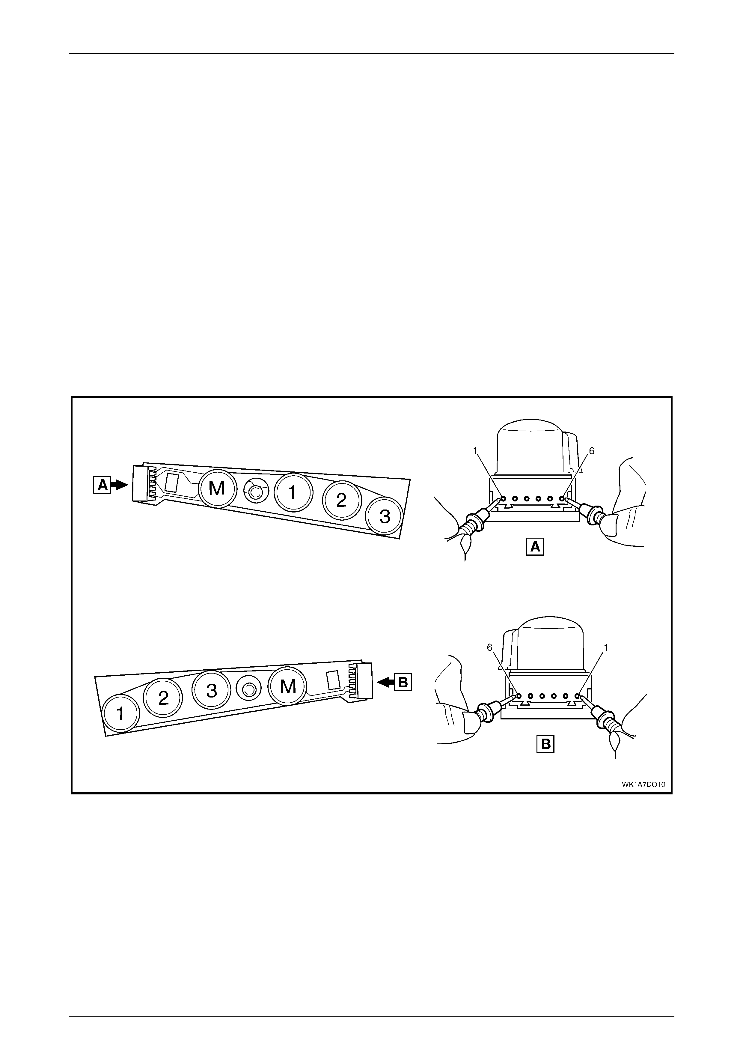
Seat Assemblies Page 1A7–287
Page 1A7–287
6.9 Memory Position Switch Test
The switch is located on the outer side of the seat, attached to the inner side of the front seat outer side cover.
Remove
To remove the memory position switch, refer to 4.4 Front Seat Outer Side Cover Assembly.
Reinstall
To reinstall the memory position switch, refer to 4.4 Front Seat Outer Side Cover Assembly.
Test
1 Place the switch in the positions as detailed in the chart in this Section. Place the probes of the digital multimeter
onto the terminals listed and take the reading. Compare the reading to the chart.
2 When testing the LED, ensure multimeter is set to diode range and note polarity of probes.
3 If the switch fails any part of the test, replace the switch assembly with a serviceable item.
Figure 1A7 – 176

Seat Assemblies Page 1A7–288
Page 1A7–288
RIGHT-HAND SEAT MEMORY POSITION SWITCH
SWITCH DE PRESSED SWITCH TERMI NAL S INDICATION IF SWITCH IS
SERVICEABLE
------------ 6 and 1, 2, 3 and 4 Open c i rcuit
Button 1 6 and 1 Continuity
Button 2 6 and 2 Continuity
Button 3 6 and 3 Continuity
Button M 6 and 4 Continuity
------------ 5 (+) probe and 6 (–) probe LED illuminated
LEFT-HAND SEAT MEMORY POSITION SWITCH
SWITCH DEPRESSED SWITCH TERMINALS INDICATION IF SWITCH IS
SERVICEABLE
------------ 1 and 3, 4, 5 and 6 Open c i rcuit
Button 1 1 and 6 Continuity
Button 2 1 and 5 Continuity
Button 3 1 and 4 Continuity
Button M 1 and 3 Continuity
------------ 2 (+) probe and 1 (–) probe LED illuminated
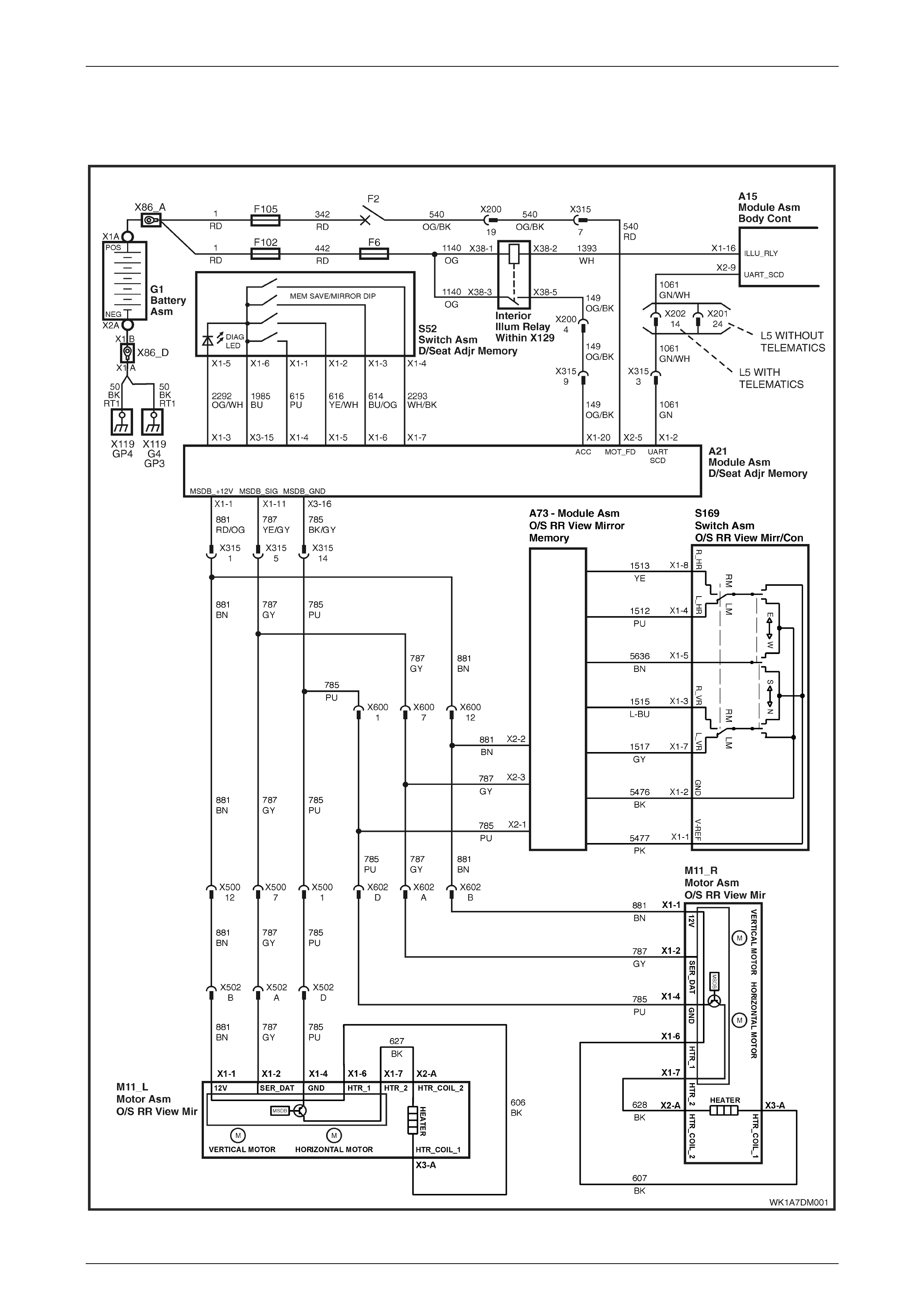
Seat Assemblies Page 1A7–289
Page 1A7–289
6.10 Electrical Diagnosis – Rear-view Mirrors
Wiri ng Diagr am – RHD
Figure 1A7 – 177
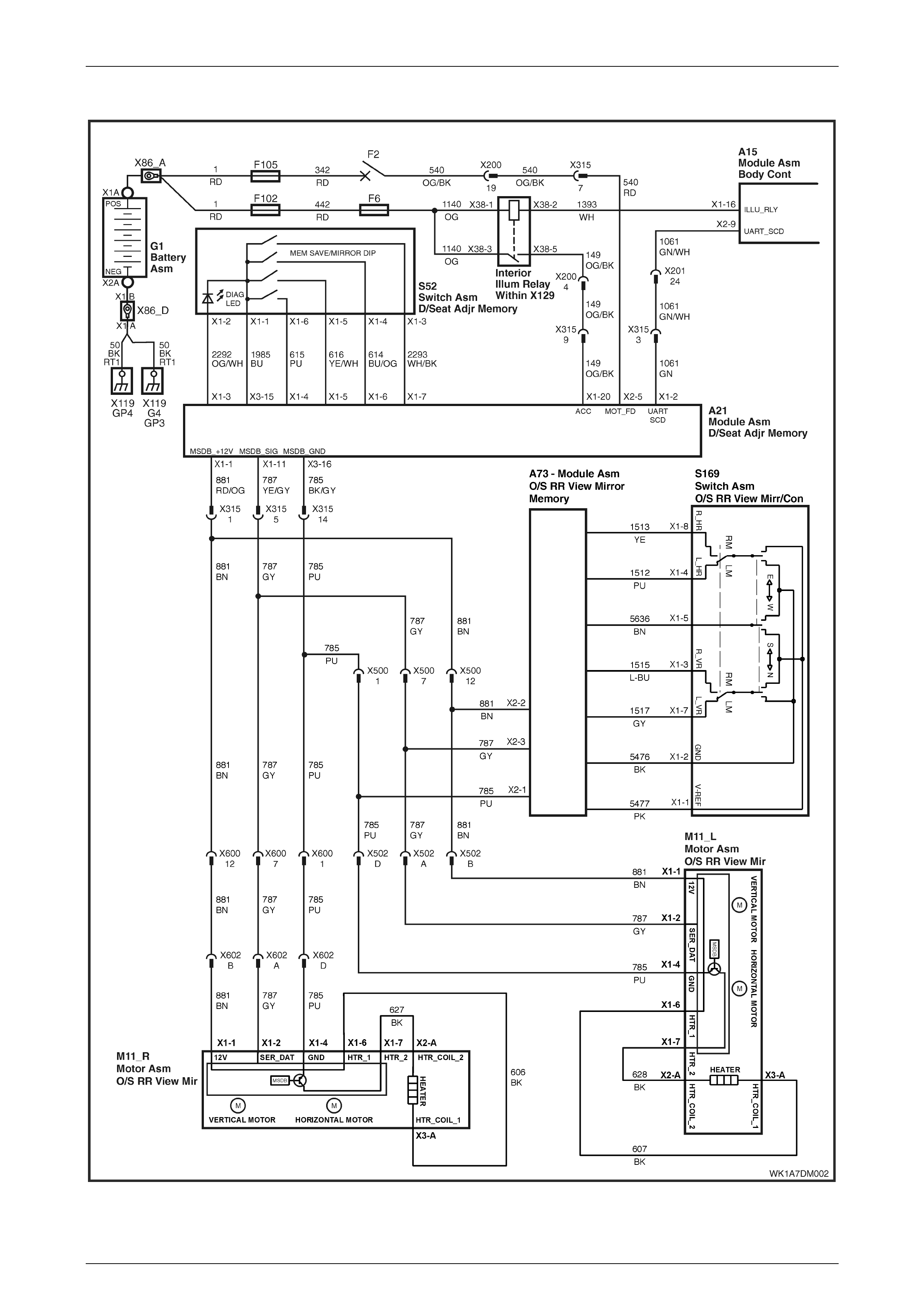
Seat Assemblies Page 1A7–290
Page 1A7–290
Wiring Diagram – LHD
Figure 1A7 – 178
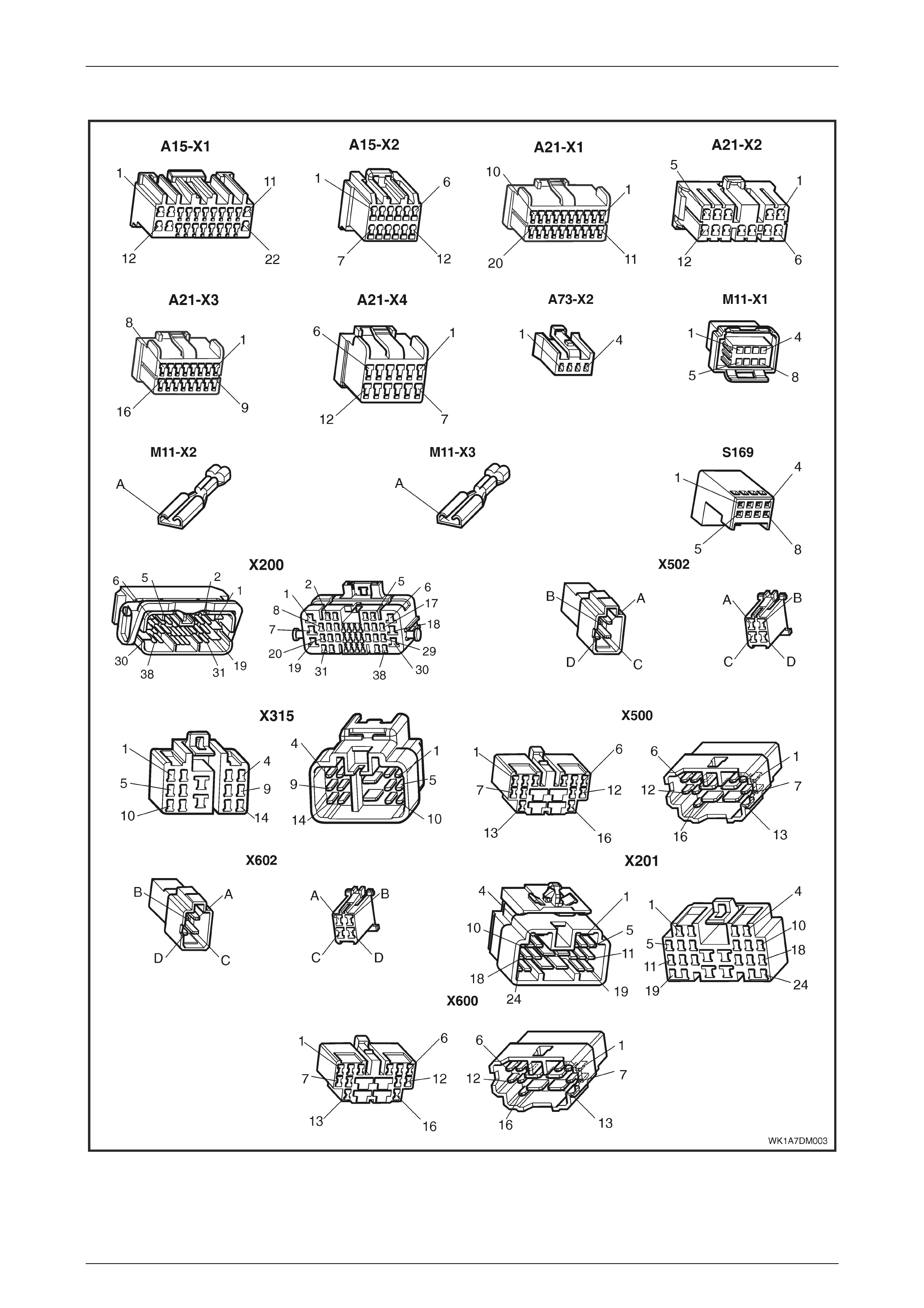
Seat Assemblies Page 1A7–291
Page 1A7–291
Connector Chart
Figure 1A7 – 179

Seat Assemblies Page 1A7–292
Page 1A7–292
Initial Check
Circuit Description
This operational check uses TECH 2 to test the functionality of the exterior rear-view mirrors and isolates which system is
faulty. The seat memory module provides electric al power, ground and serial data communications to the mirrors. As
described in 1 General Information, the mirrors can be controlled:
• manually by the mirror control switch located on the driver's door,
• by the pressing any of the memory buttons on the memory position switch, and
• dip the pass enger's mirror when reversing.
Refer to 1 General Information for further details on the operation of the exterior rear-view mirror.
Refer to Wiring Diagram – RHD for right-hand drive vehicles or Wiring Diagram – LHD for left-hand drive vehicles and
Connector Chart to aid in diagnosis of the exterior rear-view mirrors and associated components.
Test Description
The followi ng numbers refer to the steps in the diagnostic chart:
1 Ensures TECH 2 can communicate with the seat memory module.
2 Checks existence of any diagnostic trouble codes.
3 Tests whether TECH 2 is receiving serial data from both the exterior rear-view mirrors and the mirror control switch
via the rear-view mirror. All serial data communications needs to be interrupted to these assemblies for TECH 2 to
display that there is a problem.
4 Tests whether serial data is being received at right exterior mirror only.
5 Tests whether serial data is being received at left exterior mirror only.
6-9 Checks that the mirror control switch is serviceable. Also checks whether the exterior rear-view mirrors and circ uits
are serviceable.
10 Checks if the mirror dip function is serviceable.
11 Checks if the mirror heating function is serviceable.
12 Checks whether the memory recall function of the exterior rear-view mirrors is serviceable. This function is
controlled by the seat memory module which transmits through the serial a signal to inform the mirrors what
position they should be in. The exterior rear-view mirror assemblies store the physical position within their own
modules. If the seat aspect of this feature is operational, the exterior rear-view mirror assembly is faulty and must
be replaced.
Notes on the Diagnostic Chart
1 For all wiring harness fault diagnosis, refer to Section 12P W i ring Diagrams.
2 For wiring harness repairs, refer to Section 12P Wiring Diagrams.
3 Refer to Section 12O Fuses, Relays and Wiring Harnes ses for harness routeing.
4 If at any time the fault is deemed to be interm ittent, refer to Section 12P Wiring Di agrams.
Step Action Yes No
1 Connect TECH 2 to the DLC.
1 Scroll to BODY \ SEAT AND EXTERIOR MIRROR MEMORY
MODULE.
2 Turn the ignition switch ON.
Does the System Identification Screen display system information?
Go to Step 2.
There is a problem
with the seat
memory module.
Refer to
6.8 Electrical
Diagnosis –
Memory Seat
2 On TECH 2, select BODY \ SEAT AND EXTERIOR MIRROR
MEMORY MODULE \ DIAGNOSTIC TROUBLE CODES \ READ
DTC INFORMATION.
Are there any diagnostic trouble codes displayed?
Go to appropriate
DTC table. Go to Step 3.

Seat Assemblies Page 1A7–293
Page 1A7–293
Step Action Yes No
3 1 On TECH 2, select BODY \ SEAT AND EXTERIOR MIRROR
MEMORY MODULE \ DIAGNOSTIC DATA DISPLAY \ INPUTS
AND OUTPUTS.
2 Scroll to BUTTON PACK COMMUNICATION.
Does TECH 2 display OK?
Go to Step 4.
Refer to No Serial
Data from Exterior
Rear-view Mirrors
in this Section.
4 1 Scroll to RIGHT EXTERIOR MIRROR COMMUNICATION.
Does the RIGHT EXTERIOR MIRROR COMMUNICATION display
OK? Go to Step 5.
Refer to No Serial
Data – Right-hand
Exterior Rear-view
Mirror in this
Section.
5 1 Scroll to LEFT EXTERIOR MIRROR COMMUNICATION.
Does the LEFT EXTERIOR MIRROR COMMUNICATION display
OK? Go to Step 6.
Refer to No Serial
Data – Left-hand
Exterior Rear-view
Mirror in this
Section.
6 1 On TECH 2, select BODY \ SEAT AND EXTERIOR MIRROR
MEMORY MODULE \ DIAGNOSTIC DATA DISPLAY \ INPUT
AND OUTPUT.
2 Scroll to RIGHT EXTERIOR MIRROR SWITCH.
3 Monitor TECH 2.
4 Move the rocker switch on the rear-view mirror switch to the
position to control the right exterior mirror.
5 Using the rear-view mirror switch:
• Press the right exterior mirror UP.
• Press the right exterior mirror DOWN.
• Press the right exterior mirror LEFT.
• Press the right exterior mirror RIGHT.
Does TECH 2 display UP, DOWN, LEFT, then RIGHT during
operation?
Go to Step 7.
Refer to Mirror
Control Switch
Inoperative in this
Section.
7 During the test in Step 6, does the right-hand exterior rear-view mirror
move in the following directions?
• When the switch is in the neutral position, the mirror does not
move.
• When the switch is in the UP position, the mirror moves up
• When the switch is in the DOWN posi tion, the mirror moves
down
• When the switch is in the RIGHT position, the mirror moves
right, and
• When the switch is in the LEFT position, the mirror moves left.
NOTE
Ensure that the mirror is not at its maximum limit of travel
in any direction when performing this test.
Go to Step 8.
Replace the right-
hand exterior rear-
view mirror
assembly, refer to
Section 12H Rea r -
view Mirrors

Seat Assemblies Page 1A7–294
Page 1A7–294
Step Action Yes No
8 1 On TECH 2, select LEFT EXTERIOR MIRROR SWITCH.
2 Monitor TECH 2.
3 Move the rocker switch on the rear-view mirror switch to the
position to contr ol the left exterior mirror.
4 Using the rear-view mirror switch:
• Press the left exterior mirror U P.
• Press the left exterior mirror D OWN.
• Press the left exterior mirror LE FT .
• Press the left exterior mirror RI G HT .
Does:
• the left exterior mirror move in all directions, and
• TECH 2 display UP, DOWN, LEFT, then RIGHT during
operation?
Go to Step 9.
Refer to Mirror
Control Switch
Inoperative in this
Section.
9 During the test in Step 8, does the left-hand exterior rear-view mirror
move in the following directions?
• When the switch is in the neutral position, the mirror does not
move.
• When the switch is in the UP position, the mirror moves up
• When the switch is in the DOWN posi tion, the mirror moves
down
• When the switch is in the RIGHT position, the mirror moves
right, and
• When the switch is in the LEFT position, the mirror moves left.
NOTE
Ensure that the mirror is not at its maximum limit of travel
in any direction when performing this test.
Go to Step 10.
Replace the left-
hand exterior rear-
view mirror
assembly, refer to
Section 12H Rea r -
view Mirrors
10 Is there is a problem with the mirror dip function? Refer to Mirror Dip
Function Check. Go to Step 11.
11 Is there is a problem with the mirror heating function? Refer to Mirror
Heating Functio n
Check Go to Step 12.
12 Is there a problem with the memory recall function of the exterior
rear-view mirrors? If both exterior rear-
view mirrors are
unable to recall
memory positions,
check the
functionality of the
seat, refer to
6.8 Electrical
Diagnosis –
Memory Seat
If only one mirror is
unable to recall
memory positions,
replace the m i rror
assembly. Refer to
Section 12H Rea r -
view Mirrors.
System
serviceable.
When all diagno ses are compl eted, ens ure all sea t components are
reconnected; clear all DTCs and verify correct operation.

Seat Assemblies Page 1A7–295
Page 1A7–295
Mirror Dip Function Check
Circuit Description
The mirror dip function is operational when:
• the mirror dip function is enabled, refer to 1 General Information for details on how to enable the dip function
• a position for the passenger's exterior rear-view mirror is stored as the mirror dip
• the transmission selector must be placed in REVERSE
Test Description
The followi ng numbers refer to the steps in the diagnostic chart:
2 Checks whether the mirror DIP function is ENABLED.
3 Checks whether the mirror DIP function operates and is posi tioned correctly.
4 Checks whether the mirror DIP function returns an ACTIVE message on TECH 2 when the transmission selector is
placed in REVERSE. Isolates whether there is a fault with the seat memory module, or there is a problem with the
serial data from the transmission selector.
Notes on the Diagnostic Chart
1 For all wiring harness fault diagnosis, refer to Section 12P W i ring Diagrams.
2 For wiring harness repairs, refer to Section 12P Wiring Diagrams.
3 Refer to Section 12O Fuses, Relays and Wiring Harnes ses for harness routeing.
4 If at any time the fault is deemed to be interm ittent, refer to Section 12P Wiring Di agrams.
Step Action Yes No
1 Has the Initial Check been performed? Go to Step 2. Refer to Initial
Check in this
Section.
2 1 On TECH 2, select BODY \ SEAT AND EXTERIOR MIRROR
MEMORY MODULE \ DIAGNOSTIC DATA DISPLAY \
MEMORY.
2 Scroll to PRIORITY 1.
3 Monitor TECH 2.
Does TECH 2 display MIRROR DIP BUTTON as ENABLED?
Go to Step 3.
Enable mirror DIP
function, refer to
1 General
Information.
Go to Step 3.
3 1 Ensure the stored mirror DIP position is noti cea bly differe nt
from the standard position of the left exterior mirror, refer to
1 General Information.
2 Check the mirror DIP function by placing the transmission
selector in reverse.
Does the mirror DIP function operate?
System
serviceable. Go to Step 4.
4 1 On TECH 2, select BODY \ SEAT AND EXTERIOR MIRROR
MEMORY MODULE \ DIAGNOSTIC DATA DISPLAY \ INPUTS
AND OUTPUTS.
2 Scroll to REVERSE GEAR.
Does TECH 2 display REVERSE GEAR as ACTIVE?
Replace the seat
memory module,
refer to 4.12 Seat
Memo r y Mod u le .
Refer to
Section 6C3–2C
Functional Check.
When all diagno ses are compl eted, ens ure all sea t components are
reconnected; clear all DTCs and verify correct operation.
Seat Assemblies Page 1A7–296
Page 1A7–296
Mirror Heating Functi on Check
Circuit Description
When the demist button the instrument panel is pressed to activate the demist function, the request is sent through the
serial data bus to the exterior rear-view mirror assemblies.
Test Description
The followi ng numbers refer to the steps in the diagnostic chart:
2 Checks whether TECH 2 confirms the demist function has been activated.
3 Checks whether the heater element in the right-hand exterior rear-view mirror operates when the ignition and rear
window demister are switched ON.
4 Checks if the right-hand mirror heater element is serviceable. Isolates whether the heater element or the exterior
rear-view mirror assembly is at fault.
5 Checks whether the heater element in the left-hand exterior rear-view mirror operates when the ignition and rear
window demister are switched ON.
6 Checks if the left-hand mirror heater element is serviceable. Isolates whether the heater element or the exterior
rear-view mirror assembly is at fault.
Notes on the Diagnostic Chart
1 For all wiring harness fault diagnosis, refer to Section 12P W i ring Diagrams.
2 For wiring harness repairs, refer to Section 12P Wiring Diagrams.
3 Refer to Section 12O Fuses, Relays and Wiring Harnes ses for harness routeing.
4 If at any time the fault is deemed to be intermittent, refer to Section 12P Wiring Diagrams.
Step Action Yes No
1 Has the Initial Check been performed? Go to Step 2. Refer to Initial
Check in this
Section.
2 1 On TECH 2, scroll to BODY \ SEAT AND EXTERIOR MIRROR
MEMORY MODULE \ DIAGNOSTIC DATA DISPLAY \ INPUT
AND OUTPUT.
2 Scroll to DEMIST REQUEST.
3 Turn the rear window demister ON.
Does TECH 2 display DEMIST REQUEST as YES?
Go to Step 3.
Refer to
Section 12J Body
Control Module.
Go to Step 3.
3 Operate the rear window demister for 2–3 minutes.
Does the right exterior mirror feel warm? Go to Step 4. Go to Step 5.
4
Turn the rear window demister OFF before removing
and replacing the right exterior mirror glass.
Test the heater element of the right-hand exterior rear-view mirror,
refer to Section 12H Rear-view Mirrors.
Is the heater element serviceable?
Replace the right-
hand exterior rear-
view mirror
assembly, refer to
Section 12H Rea r -
view Mirrors.
Replace the right-
hand exterior rear-
view mirror glass,
refer to Section
12H Rear-view
Mirrors.
Go to Step 5.
5 Operate the rear window demister for 2–3 minutes.
Does the left exterior mirror feel warm? System
serviceable. Go to Step 6.

Seat Assemblies Page 1A7–297
Page 1A7–297
Step Action Yes No
6
Turn the rear window demister OFF before removing
and replacing the left exterior mirror glass.
Test the heater element of the left-hand exterior rear-view mirror,
refer to Section 12H Rear-view Mirrors.
Is the heater element serviceable?
Replace the left-
hand exterior rear-
view mirror
assembly, refer to
Section 12H Rea r -
view Mirrors.
Replace the left-
hand exterior rear-
view mirror glass,
refer to Section
12H Rear-view
Mirrors.
When all diagno ses are compl eted, ens ure all sea t components are
reconnected; clear all DTCs and verify correct operation.

Seat Assemblies Page 1A7–298
Page 1A7–298
No Serial Data from Exterior Rear-view Mirrors
Circuit Description
The exterior rear-view mirrors have a common power, ground and serial data connector at the seat memory module. If
the circuit is followed, there are two splices in each of the power, ground and data communication circuits. In this test, as
there are not serial data communications with any of the exterior rear-view mirrors, it is assumed that the fault will be in a
location common to all circuits.
Refer to Wiring Diagram – RHD for right-hand drive vehicles or Wiring Diagram – LHD for left-hand drive vehicles and
Connector Chart to aid in diagnosis of the exterior rear-view mirrors and associated components.
Test Description
The followi ng numbers refer to the steps in the diagnostic chart:
2 Checks if the connectors common to the serial data communication for the exterior rear-view mirrors are secure.
3 Checks if battery voltage is present for the exterior rear-view mirror system at the seat memory module.
4 Checks if the seat memory module is supplying a ground circuit for the exterior rear-view mirror system.
5 Checks the battery supply circuit for a short to ground.
6 Checks the ground circuit for a short to battery.
7 Checks if there is continuity in the serial data circuit between A22 – X1 pin 11 and X500 pin 7. Isolates whether the
is an open-circuit in circuit 787 that will affect all the exterior rear-view mirrors, or the seat memory module is at
fault.
Notes on the Diagnostic Chart
1 For all wiring harness fault diagnosis, refer to Section 12P W i ring Diagrams.
2 For wiring harness repairs, refer to Section 12P Wiring Diagrams.
3 Refer to Section 12O Fuses, Relays and Wiring Harnes ses for harness routeing.
4 If at any time the fault is deemed to be interm ittent, refer to Section 12P Wiring Di agrams.
Step Action Yes No
1 Has the Initial Check been performed? Go to Step 2. Refer to Initial
Check in this
Section.
2 Ensure that the following connectors are secure:
• A21 – X1
• A21 – X3
• X315
Are all the connectors secure?
Go to Step 3. Secure the relevant
connectors.
3 1 Disconnect harness connector A21 – X1.
2 Using a multimeter and Tool No. KM609–20, probe between the
seat memory module connector A21 – X1 pin 1 and a known
ground, and check for battery voltage (refer to note 1).
Is battery vo ltage present?
Go to Step 4.
Replace the seat
memory module,
refer to 4.12 Seat
Memory Module.
4 1 Using a multimeter and Tool No. KM609–20, probe between the
seat memory module connector A21 – X3 pin 16 and a known
ground, and check for continuity (refer to note 1).
Is the continuity present?
Go to Step 5.
Replace the seat
memory module,
refer to 4.12 Seat
Memory Module.

Seat Assemblies Page 1A7–299
Page 1A7–299
Step Action Yes No
5 1 Using a multimeter and Tool No. KM609–20, probe between the
harness connector A21 – X1 pin 1 and a known ground, and
check for continuity (refer to no te 1).
Is there continuity present?
There is a short to
ground in circuit
881.
Repair or re place
circuit 881 as
required (refer to
note 2).
Go to Step 6.
6 1 Using a multimeter and Tool No. KM609–20, probe between the
harness connector A21 – X3 pin 16 and a known ground, and
check for battery voltage (refer to note 1).
Is battery vo ltage present?
There is a short to
battery in circuit
785.
Repair or re place
circuit 785 as
required (refer to
note 2).
Go to Step 7.
7 1 Using a multimeter and Tool No. KM609–20, probe between the
harness connector A21 – X1 pin 11:
• X500 pin 7 for right-hand drive, or
• X600 pin 7 for left-hand drive,
and check for continuity (refer to note 1).
Is there continuity present?
Replace the seat
memory module,
refer to 4.12 Seat
Memo r y Mod u le .
There is an open-
circuit in circuit 787.
This open circuit
should be between
connector A21 –
X1 pin 11 and the
first splice on circui t
787 as there is no
data
communications for
the exterior rear-
view mirrors.
Repair or repl ace
circuit 787 as
required (refer to
note 2).
When all diagno ses are compl eted, ens ure all sea t components are
reconnected; clear all DTCs and verify correct operation.

Seat Assemblies Page 1A7–300
Page 1A7–300
No Serial Data – Right-hand Exterior Rear-view Mirror
Circuit Description
Refer to Wiring Diagram – RHD for right-hand drive vehicles or Wiring Diagram – LHD for left-hand drive vehicles and
Connector Chart to aid in diagnosis of the exterior rear-view mirrors and associated components.
Test Description
The followi ng numbers refer to the steps in the diagnostic chart:
2 Checks whether the there is battery voltage supplied to the right-hand exterior rear-view mirror. Isolates whether
there is a fault in circuit 881 between X602 and A21 – X1.
3 Checks whether the ground circuit for the right-hand exterior rear-view mirror is complete. Isolates whether there is
a fault in circuit 785 between X602 and A21 – X3.
4 Checks whether the serial data circuit for the right-hand exterior rear-view mirror for integrity. Isolates whether there
is fault in circuit 787 between connectors A21 – X1 and X602, or the right-hand exterior rear-view mirror assembly
is faulty.
Notes on the Diagnostic Chart
1 For all wiring harness fault diagnosis, refer to Section 12P W i ring Diagrams.
2 For wiring harness repairs, refer to Section 12P Wiring Diagrams.
3 Refer to Section 12O Fuses, Relays and Wiring Harnes ses for harness routeing.
4 If at any time the fault is deemed to be interm ittent, refer to Section 12P Wiring Di agrams.
Step Action Yes No
1 Has the Initial Check been performed? Go to Step 2. Refer to Initial
Check in this
Section.
2 1 Backprobe connector X602 pin B with a test lamp (refer to
note 1).
Does the test lamp illuminate? Go to Step 3.
There is a fault in
circuit 881 betw een
X602 and A21 –
X1.
Repair or repl ace
circuit 881 (refer to
note 2).
3 1 Disconnect harness connector X602.
2 Using a multimeter and Toll No . KM609–20, probe between
harness connector X602 pin D and a known ground, and check
for continuity (refer to note 1).
Is there continuity present?
Go to Step 4.
There is a fault in
circuit 785 betw een
X602 and A21 –
X3.
Repair or repl ace
circuit 785 (refer to
note 2).
4 1 Disconnect harness connector A21 – X1.
2 Using a multimeter and Tool No. KM609–20, probe between
harness connectors A21 – X1 pin 11 and X602 pin A, and
check for continuity (refer to no te 1).
Is there continuity present?
Replace the right-
hand exterior rear-
view mirror
assembly, refer to
Section 12H Rea r -
view Mirrors.
There is an open-
circuit in circuit 787
between
connectors A21 –
X1 and X6 02.
Repair or repl ace
circuit 787 as
required (refer to
note 2).
When all diagno ses are compl eted, ens ure all sea t components are
reconnected; clear all DTCs and verify correct operation.

Seat Assemblies Page 1A7–301
Page 1A7–301
No Serial Data – Left-hand Exterior Rear-view Mirror
Circuit Description.
Refer to Wiring Diagram – RHD for right-hand drive vehicles or Wiring Diagram – LHD for left-hand drive vehicles and
Connector Chart to aid in diagnosis of the exterior rear-view mirrors and associated components.
Test Description
The followi ng numbers refer to the steps in the diagnostic chart:
2 Checks whether the there is battery voltage supplied to the left-hand exterior rear-view mirror. Isolates whether
there is a fault in circuit 881 between X502 and A21 – X1.
3 Checks whether the ground circuit for the left-hand exterior rear-view mirror is complete. Isolates whether there is a
fault in circuit 785 betw een X502 and A21 – X3.
4 Checks whether the serial data circuit for the left-hand exterior rear-view mirror for integrity. Isolates whether there
is fault in circuit 787 between connectors A21 – X1 and X502, or the left-hand exterior rear-view mirror assembly is
faulty.
Notes on the Diagnostic Chart
1 For all wiring harness fault diagnosis, refer to Section 12P Wiring Diagrams.
2 For wiring harness repairs, refer to Section 12P Wiring Diagrams.
3 Refer to Section 12O Fuses, Relays and Wiring Harnes ses for harness routeing.
4 If at any time the fault is deemed to be interm ittent, refer to Section 12P Wiring Di agrams.
Step Action Yes No
1 Has the Initial Check been performed? Go to Step 2. Refer to Initial
Check in this
Section.
2 1 Backprobe connector X502 pin B with a test lamp (refer to
note 1).
Does the test lamp illuminate? Go to Step 3.
There is a fault in
circuit 881 betw een
X502 and A21 –
X1.
Repair or repl ace
circuit 881 (refer to
note 2).
3 1 Disconnect harness connectors X502.
2 Using a multimeter and Toll No . KM609–20, probe between
harness connector X502 pin D and a known ground, and check
for continuity (refer to note 1).
Is there continuity present?
Go to Step 4.
There is a fault in
circuit 785 betw een
X502 and A21 –
X3.
Repair or repl ace
circuit 785 (refer to
note 2).
4 1 Disconnect harness connector A21 – X1.
2 Using a multimeter and Tool No. KM609–20, probe between
harness connectors A21 – X1 pin 11 and X502 pin A, and
check for continuity (refer to no te 1).
Is there continuity present?
Replace the left-
hand exterior rear-
view mirror
assembly, refer to
Section 12H Rea r-
view Mirrors.
There is an open-
circuit in circuit 787
between
connectors A21 –
X1 and X5 02.
Repair or repl ace
circuit 787 as
required (refer to
note 2).
When all diagno ses are compl eted, ens ure all sea t components are
reconnected; clear all DTCs and verify correct operation.

Seat Assemblies Page 1A7–302
Page 1A7–302
Mirror Control Switch Inoperative
Circuit Description
When the mirror control switch is used, the signal that it generates is converted by the rear-view mirror module to serial
data. It is then transmitted over the serial data bus. The exterior rear-view mirrors then receive this serial data and move
the appropriate exterior rear-view mirror in the direction that was pressed on the mirror control switch.
Refer to Wiring Diagram – RHD for right-hand drive vehicles or Wiring Diagram – LHD for left-hand drive vehicles and
Connector Chart to aid in diagnosis of the exterior rear-view mirrors and associated components.
Test Description
The followi ng numbers refer to the steps in the diagnostic chart:
2 Checks if the mirror control switch is servic eable.
3 Checks whether there is battery power to the rear view mirror module. Isol ates whether there is a fault in circuit 881
between A73 – X2 and A21 – X1.
4 Checks whether there is battery power to the mirror control switch. Isolates whether the rear view mirror module is
at fault.
5 Checks if the ground circuit for the rear view mirror module is complete. Isolates whether there is a fault in circuit
785 between A73 – X2 and A21 – X1.
6 Checks is the ground circuit for the mirror control switch is complete. Isolates whether the rear view mirror module
is at fault.
7 Checks if there is continuity on the serial data bus between connectors A73 – X2 and A21 – X1. Isolates whether
there is an open-circuit in circuit 787 between connectors A73 – X2 and A21 – X1, or the rear view memory module
is at fault.
Notes on the Diagnostic Chart
1 For all wiring harness fault diagnosis, refer to Section 12P W i ring Diagrams.
2 For wiring harness repairs, refer to Section 12P Wiring Diagrams.
3 Refer to Section 12O Fuses, Relays and Wiring Harnes ses for harness routeing.
4 If at any time the fault is deemed to be interm ittent, refer to Section 12P Wiring Diagrams.
Step Action Yes No
1 Has the Initial Check been performed? Go to Step 2. Refer to Initial
Check in this
Section.
2 Test the mirror control switch, refer to Section 12H, 2.3 Mirror Control
Switch in the MY 2003 VY and V2 Service Operations.
Is the mirror control switch serviceable? Go to Step 3.
Replace the mirror
control sw itch, ref er
to Section 12H,
2.3 Mirror Control
Switch in the
MY 2003 VY and
V2 Service
Operations
3 Backprobe connector A73 – X2 pin 2 with a test lamp (refer to
note 1).
Does the test lamp illuminate? Go to Step 4.
There is a fault in
circuit 881 betw een
A73 – X2 and
A21 – X1.
Repair or repl ace
circuit 881 as
required (refer to
note 2).
4 Backprobe connector S169 – X1 pin 1 with a test lamp (refer to
note 1).
Does the test lamp illuminate? Go to Step 5.
Replace the rear
view mirror module,
refer to Section
1A5, 2.2 Rear View
Mirror Module.

Seat Assemblies Page 1A7–303
Page 1A7–303
Step Action Yes No
5 1 Using a multim eter and Tool No. KM609–20, backprobe
between connector A73 –X2 pin 1 and a known ground, and
check for continuity (refer to no te 1).
Is there continuity present? Go to Step 6.
There is a fault in
circuit 785 betw een
A73 – X2 and
A21 – X1.
Repair or repl ace
circuit 785 as
required (refer to
note 2).
6 1 Using a multim eter and Tool No. KM609–20, backprobe
between connector S169 – X1 pin 2 and a known ground,
check for continuity (refer to no te 1).
Is there continuity present?
Go to Step 7.
Replace the rear
view mirror module,
refer to Section
1A5, 2.2 Rear View
Mirror Module.
7 1 Disconnect harness connectors A21 – X1 and A73 – X2.
2 Using a multimeter and Tool No. KM609–20, probe between
harness connectors A73 –X2 pin 3 and a A21 – X1 pin 11, and
check for continuity (refer to no te 1).
Is there continuity present?
Replace the rear
view mirror module,
refer to Section
1A5, 2.2 Rear View
Mirror Module.
There is an open-
circuit in 787
between
connectors A73 –
X2 and A21 – X1.
Repair or repl ace
circuit 787 (refer to
note 2).
When all diagno ses are compl eted, ens ure all sea t components are
reconnected; clear all DTCs and verify correct operation.

Seat Assemblies Page 1A7–304
Page 1A7–304
7 Service Operations – Rear Seat
7.1 Rear Seat Usage Chart
How To Use This Chart
Eight rear seat configurations are used in the MY 2004 WK Series vehicles. The following usage chart is provided to help
determine the rear seat type fitted to the vehicle. This is important prior to any repairs being performed, as the part
requiring replacement may not be serviceable.
To determine the rear seat type fitted to the vehicle, obtain the vehicle Level, the seat fabric type and then establish if the
vehicle has an armrest and/or headrest. Using the chart will lead to the elimination of all other seat combinations,
allowing the identification of the rear seat type and the construction of the seat. Finally, refer to the Figure shown in the
rear seat type column for a component breakdown of the rear seat assembly.
1 Vehicle – Vehicle Level identification.
2 Fabric – Cloth or Leather seat covers.
3 Armrest with Compartment. – If the rear seat-back as sembly is fitted with an armrest which, incorporates a
convenienc e compartment.
4 Head Restraint – If the rear seat-back is fitted with a headrest.
5 Centre Head Restraint – If the rear seat is fitted with a centre headrest mounted in the centre tray.
6 Construction – Surebond refers to the seat cover being glued to the seat pad and only serviced as a cover and
pad assembly. Hook and Loop refers to the seat cover being able to be attached to the seat pad with a Velcro type
material and both being serviced as separate parts. Conventional Pull-down refers to the seat cover being attached
to the pad and frame with a retainer wire and hog rings, with all parts being serviced.
7 Rear Seat Type – Identifies the rear seat type and provides reference to the following illustrations which show a
breakdown of the serviced component for each rear seat assembly.

Seat Assemblies Page 1A7–305
Page 1A7–305
Domestic
Vehicle Fabric Armrest
(With
Compartment)
Head
Restraint Centre Head
Restraint Construction Rear Seat Type
(Refer to)
Statesman
Level 4 Cloth Yes Yes Yes Conventional
Pull-down 5
(Figure 1A7 –
178)
Statesman
Level 4 Leather Yes Yes Yes Conventional
Pull-down 6
(Figure 1A7 –
179)
Caprice
Level 5
Two
Passenger
Rear Seat
Leather Yes Yes Yes Conventional
Pull-down 7
(Figure 1A7 –
180)
Caprice
Level 5
Three
Passenger
Rear Seat
Leather Yes Yes Yes Conventional
Pull-down 8
(Figure 1A7 –
181)
Gulf States
Vehicle Fabric Armrest
(With
Compartment)
Head
Restraint Centre head
Restraint Construction Rear Seat Type
(Refer to)
Caprice LS
Level 1 Cloth No No No Surebond 1
(Figure 1A7 –
180)
Caprice LTZ
Level 2 Cloth No Yes No Conventional
Pull-down 2
(Figure 1A7 –
175)
Caprice LTZ
Level 2 Leather No Yes No Conventional
Pull-down 3
(Figure 1A7 –
176)
Caprice SS
Level 3 Leather No Yes Yes Hook and Loop 4
(Figure 1A7 –
177)
Caprice
Royale
Level 5
Two
Passenger
Rear Seat
Leather Yes Yes Yes Conventional
Pull-down 7
(Figure 1A7 –
180)
Caprice
Royale
Level 5
Three
Passenger
Rear Seat
Leather Yes Yes Yes Conventional
Pull-down 8
(Figure 1A7 –
181)
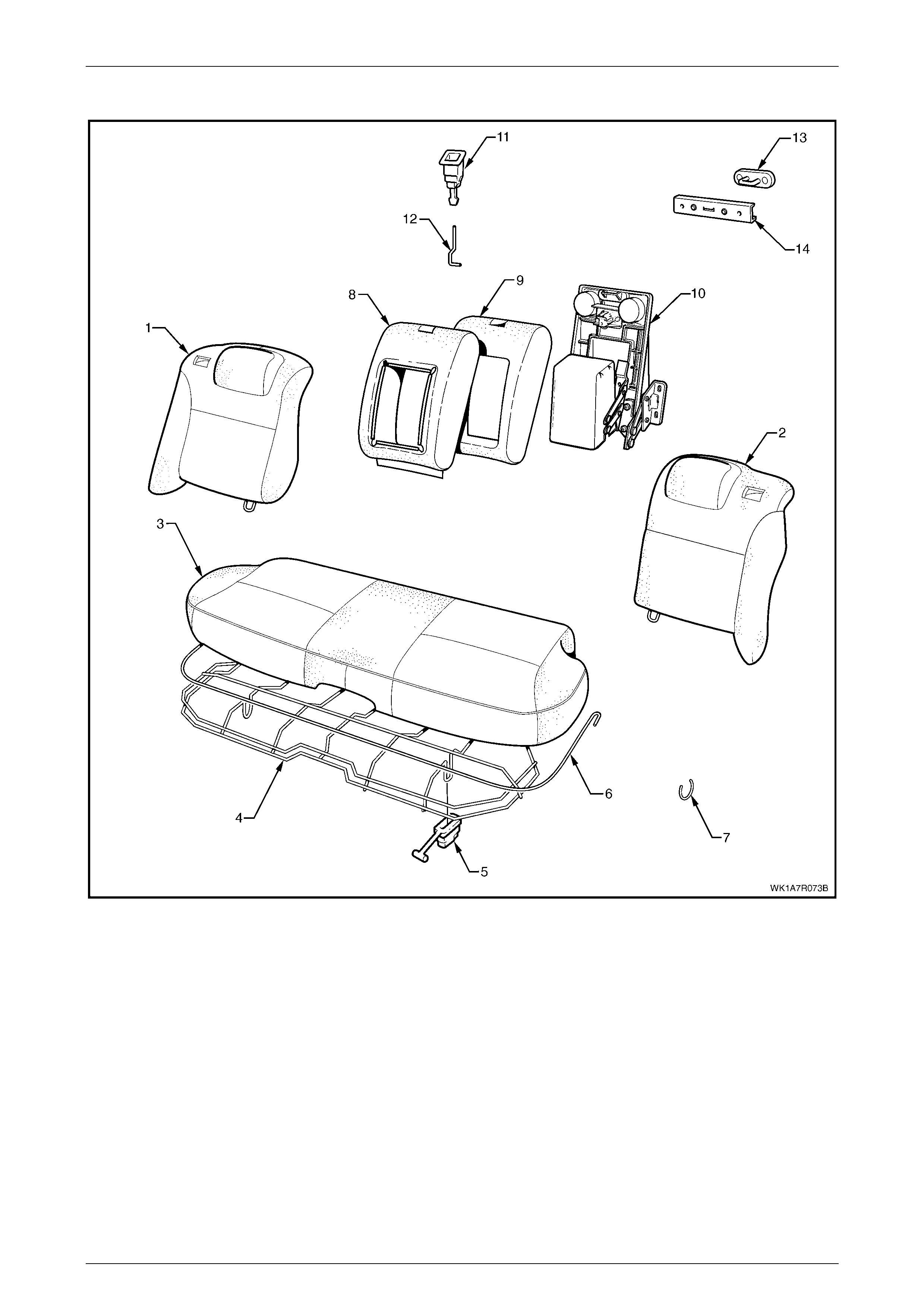
Seat Assemblies Page 1A7–306
Page 1A7–306
Rear Seat Type 1
Figure 1A7 – 180
Legend
1 Rear Seat-back Assembly, RH
2 Rear Seat-back Assem bly, LH
3 Rear Seat Cushion Cover and Pad Ass embly
4 Rear Seat Cushion Frame
5 Rear Seat Cushion Release Handle, Two Places
6 Rear Seat Cushion Cover Wi re Retainer
7 Hog Ring
8 Rear Seat-back Cent re Cover
9 Rear Seat-back Cent re Pad
10 Rear Seat-back Centre Tray and Armrest Assem bl y ∗
11 Rear Seat-back Centre Release Button
12 Release Butt on Rod
13 Rear Seat-back Cent re Lock St riker
14 Rear Seat-back Cent re Striker Cover
* Refer to Figure 1A7 – 188 for a breakdown of the rear seat-back centre armrest assembly.
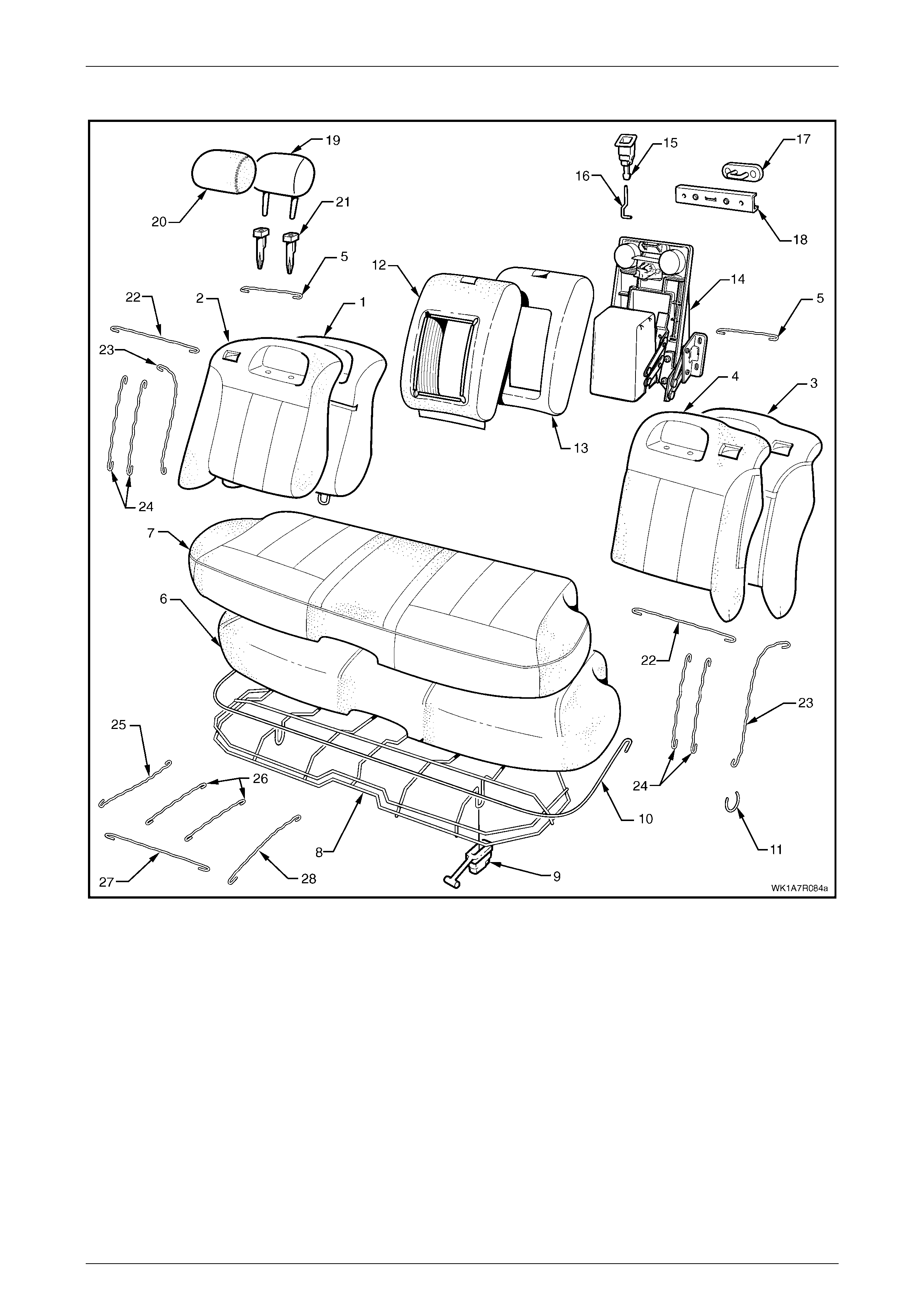
Seat Assemblies Page 1A7–307
Page 1A7–307
Rear Seat Type 2
Figure 1A7 – 181

Seat Assemblies Page 1A7–308
Page 1A7–308
Legend
1 Rear Seat-back Pad and Frame Assembly, RH
2 Rear Seat-back Cover Assembly, RH
3 Rear Seat-back Pad and Frame Assembly, LH
4 Rear Seat-back Cover Assembly, LH
5 Rear Seat-back Cover Ret a i ner Wire
6 Rear Seat Cushion Pad
7 Rear Seat Cushion Cover
8 Rear Seat Cushion Frame
9 Rear Seat Cushion Release Handle, Two Places
10 Rear Seat Cushion Cover Ret ai ner W i re
11 Hog Ring
12 Rear Seat-back Cent re Cover
13 Rear Seat-back Cent re Pad
14 Rear Seat-back Centre Tray and Armrest Assem bl y ∗
∗∗
∗
15 Rear Seat-back Centre Release Button
16 Release Butt on Rod
17 Rear Seat-back Cent re Lock St riker
18 Rear Seat-back Cent re Striker Cover
19 Rear Seat-back Head Restraint Pad Assembly, One Place
Each Side
20 Head Restraint Cover, One Place Eac h Side
21 Head Restraint Sl eeve, Two Places Each Side
22 Rear Seat-back Upper Hori zont al Groove Retainer Wire, RH
23 Rear Seat-back Outer Groove Retainer Wire, RH
24 Rear Seat-back Upper Hori zont al Groove Retai ner Wire, LH
25 Rear Seat Cushion Cover Outer Retainer W i re, Two Places
26 Rear Seat Cushion Cover Cent re Retainer Wi re, Four
Places
27 Rear Seat Cushion Cover Front Retai ner Wi re, Two Places
28 Rear Seat Cushion Inner Retaining Wire, Two Places
* Refer to Figure 1A7 – 188 for a breakdown of the rear seat-back centre armrest assembly.
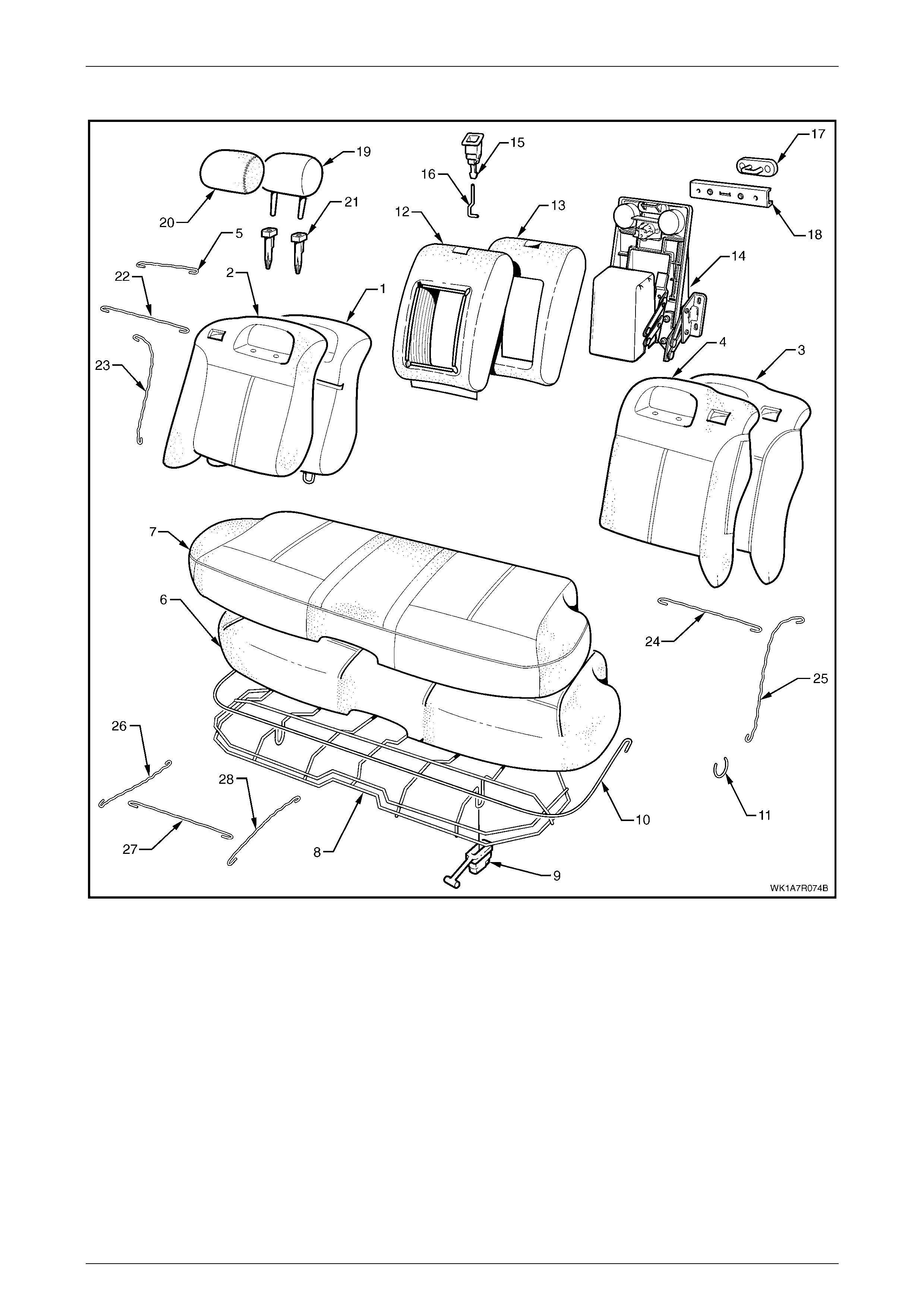
Seat Assemblies Page 1A7–309
Page 1A7–309
Rear Seat Type 3
Figure 1A7 – 182

Seat Assemblies Page 1A7–310
Page 1A7–310
Legend
1 Rear Seat-back Pad and Frame Assembly, RH
2 Rear Seat-back Cover, RH
3 Rear Seat-back Pad and Frame Assembly, LH
4 Rear Seat-back Cover, LH
5 Rear Seat-back Cover Retainer Wire, One Place Each Side
6 Rear Seat Cushion Pad
7 Rear Seat Cushion Cover
8 Rear Seat Cushion Frame
9 Rear Seat Cushion Release Handle, Two Places
10 Rear Seat Cushion Cover Ret ai ner W i re
11 Hog Ring
12 Rear Seat-back Cent re Cover
13 Rear Seat-back Cent re Pad
14 Rear Seat-back Centre Tray and Armrest Assem bl y ∗
∗∗
∗
15 Rear Seat-back Centre Release Button
16 Release Butt on Rod
17 Rear Seat-back Cent re Lock St riker
18 Rear Seat-back Cent re Striker Cover
19 Rear Seat-back Head Restraint Pad Assembly, One Place
Each Side
20 Head Restraint Cover, One Place Eac h Side
21 Head Restraint Sl eeve, Two Places Each Side
22 Rear Seat-back Upper Hori zont al Groove Retainer Wire, RH
23 Rear Seat-back Outer Retainer Wire, RH
24 Rear Seat-back Upper Hori zont al Groove Retai ner Wire, LH
25 Rear Seat-back Outer Ret ai ner W ire, LH
26 Rear Seat Cushion Cover Outer Retainer W i re, Two Places
27 Rear Seat Cushion Cover Front Retainer Wi re, Two Plac es
28 Rear Seat Cushion Inner Retaining Wire, Two Places
∗∗∗∗ Refer to Figure 1A7 – 188 for a breakdown of the rear seat-back centre armrest assembly.
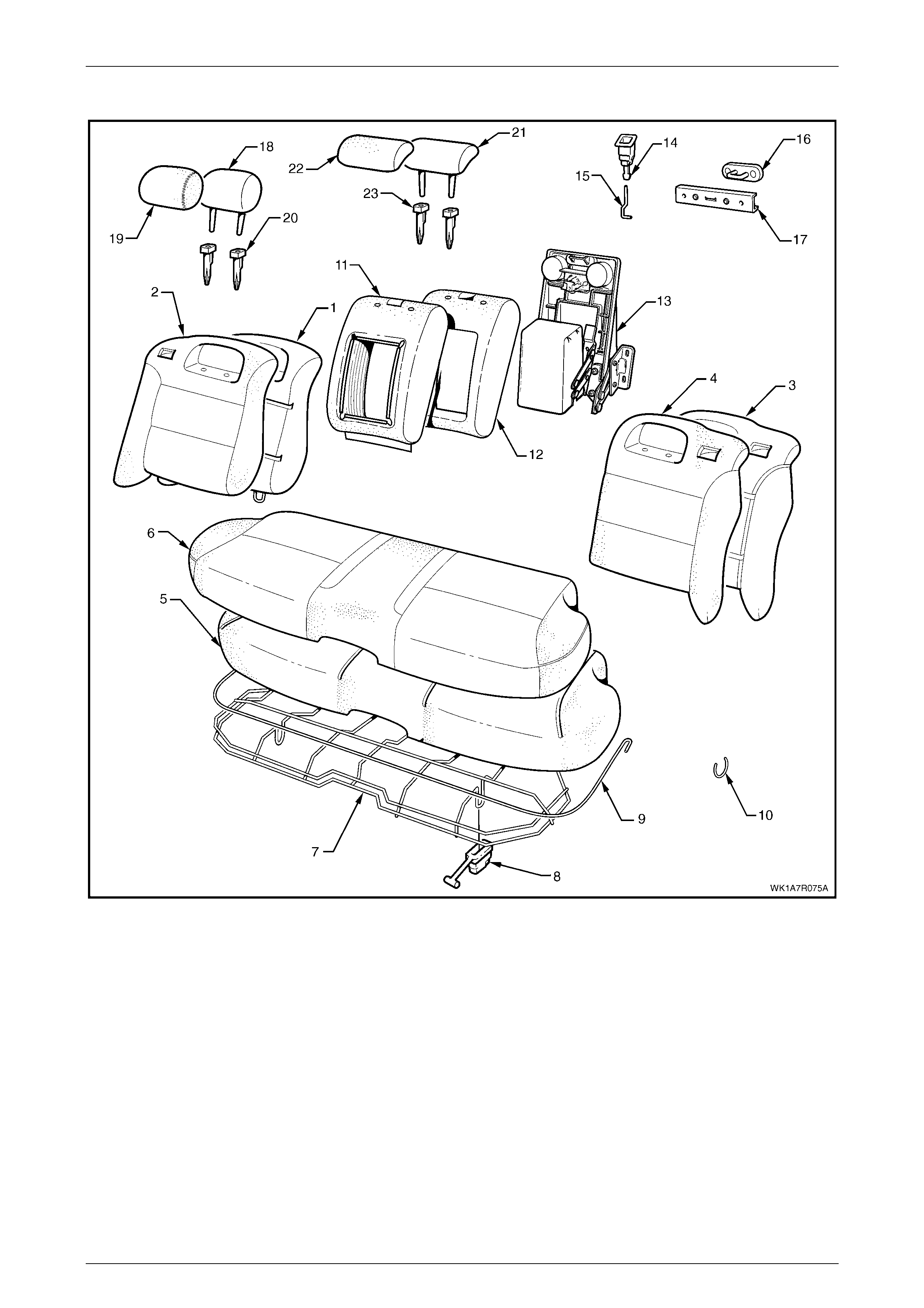
Seat Assemblies Page 1A7–311
Page 1A7–311
Rear Seat Type 4
Figure 1A7 – 183

Seat Assemblies Page 1A7–312
Page 1A7–312
Legend
1 Rear Seat-back Pad and Frame Assembly, RH
2 Rear Seat-back Cover, RH
3 Rear Seat-back Pad and Frame Assembly, LH
4 Rear Seat-back Cover, LH
5 Rear Seat Cushion Pad
6 Rear Seat Cushion Cover
7 Rear Seat Cushion Frame
8 Rear Seat Cushion Release Handle, Two Places
9 Rear Seat Cushion Cover Ret ai ner W i re
10 Hog Ring
11 Rear Seat-back Cent re Cover
12 Rear Seat-back Cent re Pad
13 Rear Seat-back Centre Tray and Armrest Assem bl y ∗
∗∗
∗
14 Rear Seat-back Centre Release Button
15 Release Butt on Rod
16 Rear Seat-back Cent re Lock St riker
17 Rear Seat-back Cent re Striker Cover
18 Rear Seat-back Head Restraint Pad Assembly, One Place
Each Side
19 Rear Seat-back Head Rest rai nt Cover, One Pl ace Each Side
20 Rear Seat-back Head Restraint Sleeve, Two Places Each
Side
21 Rear Seat-back Head Centre Head Restraint Pad Assembly
22 Rear Seat-back Head Centre Head Res traint Cover
23 Rear Seat-back Head Centre Head Restraint Sleeve, Two
Places
* Refer to Figure 1A7 – 188 for a breakdown of the rear seat-back centre armrest assembly.
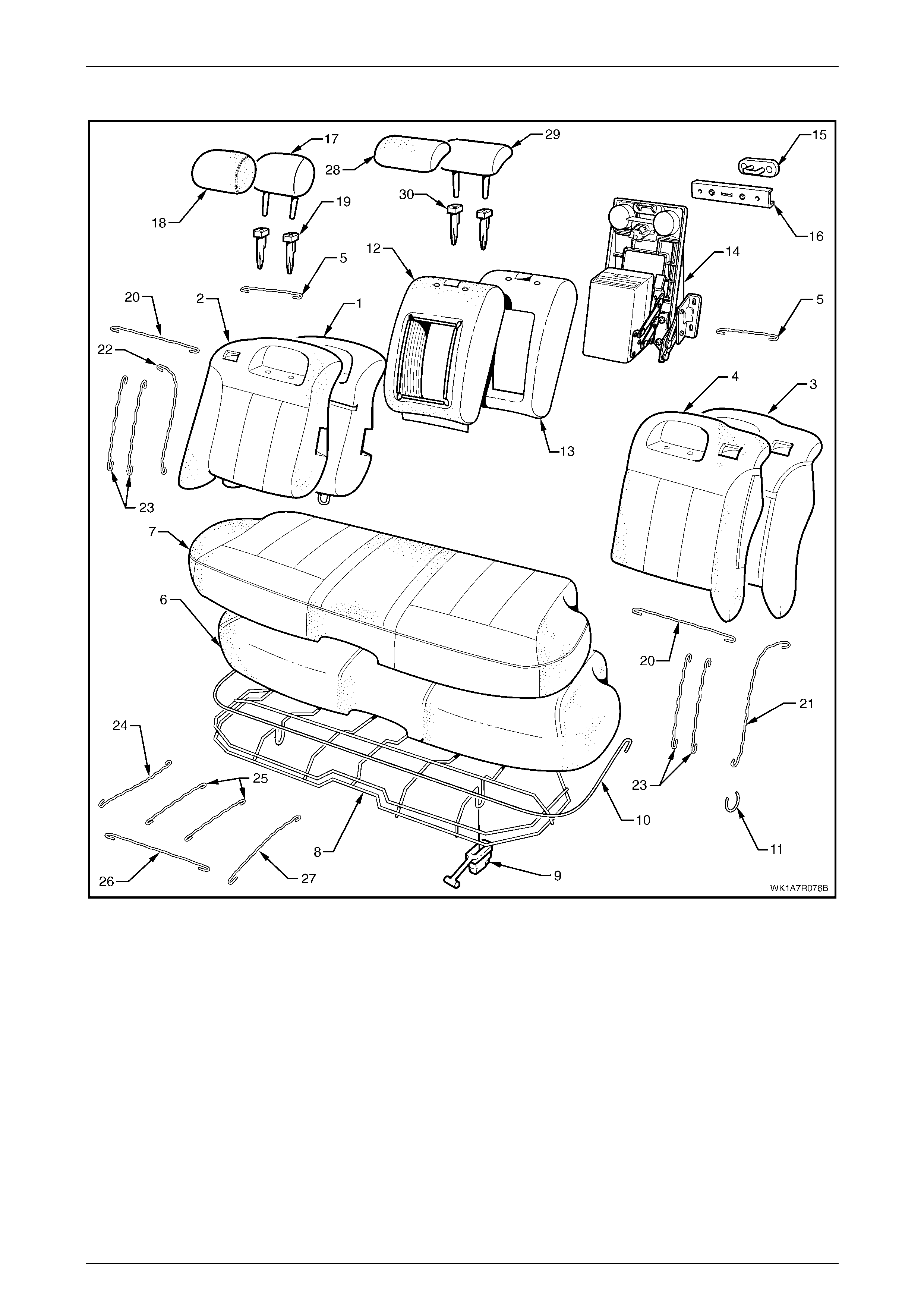
Seat Assemblies Page 1A7–313
Page 1A7–313
Rear Seat Type 5
Figure 1A7 – 184

Seat Assemblies Page 1A7–314
Page 1A7–314
Legend
1 Rear Seat-back Pad and Frame Assembly, RH
2 Rear Seat-back Cover, RH
3 Rear Seat-back Pad and Frame Assembly, LH
4 Rear Seat-back Cover, LH
5 Rear Seat-back Cover Ret a i ner Wire
6 Rear Seat Cushion Pad
7 Rear Seat Cushion Cover
8 Rear Seat Cushion Frame
9 Rear Seat Cushion Release Handle, Two Places
10 Rear Seat Cushion Cover Ret ai ner W i re
11 Hog Ring
12 Rear Seat-back Cent re Cover
13 Rear Seat-back Cent re Pad
14 Rear Seat-back Centre Tray and Armrest Assem bl y ∗
∗∗
∗
15 Rear Seat-back Cent re Lock St riker
16 Rear Seat-back Cent re Striker Cover
17 Rear Seat-back Head Restraint Pad Assembly, One Place
Each Side
18 Rear Seat-back Head Rest rai nt Cover, One Pl ace Each Side
19 Rear Seat-back Head Restraint Sleeve, Two Places Each
Side
20 Rear Seat-back Upper Hori zont al Groove Retai ner Wire
21 Rear Seat-back Outer Ret ai ner W ire, LH
22 Rear Seat-back Outer Retainer Wire, RH
23 Rear Seat-back Vertical Groove Retainer Wire
24 Rear Seat Cushion Cover Outer Retainer W i re, Two Places
25 Rear Seat Cushion Cover Cent re Retainer Wi re, Four
Places
26 Rear Seat Cushion Front Retainer Wire, Two Places
27 Rear Seat Cushion Cover Inner Retainer Wi re, Two Plac es
28 Rear Seat-back Centre Head Restraint Cover
29 Rear Seat-back Cent re Head Restraint Pad
30 Rear Seat-back Cent re Head Restraint S leeve, Two Places
∗∗∗∗ Refer to Figure 1A7 – 189 for a breakdown of the rear seat-back centre tray and armrest assembly.
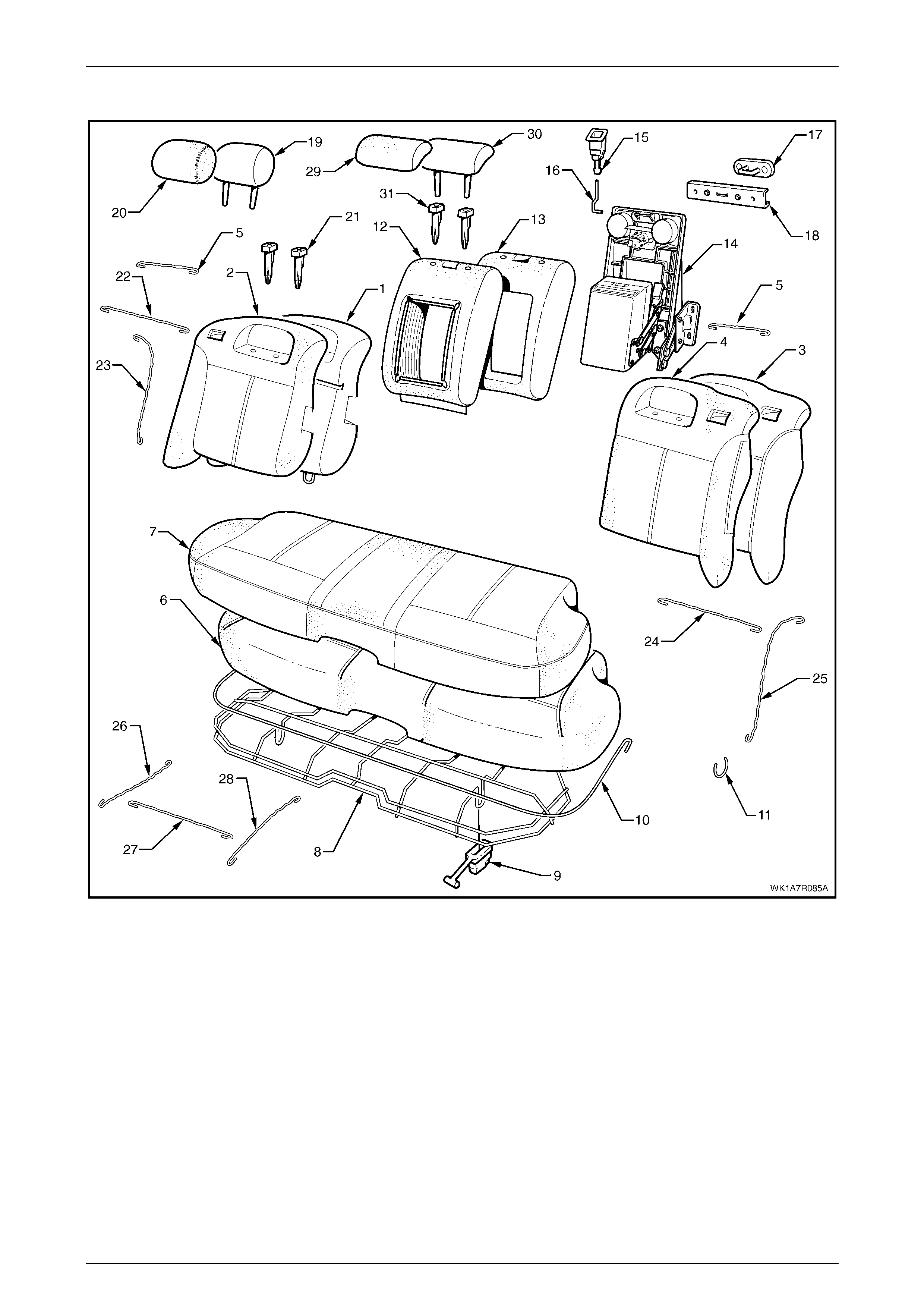
Seat Assemblies Page 1A7–315
Page 1A7–315
Rear Seat Type 6
Figure 1A7 – 185

Seat Assemblies Page 1A7–316
Page 1A7–316
Legend
1 Rear Seat-back Pad and Frame Assembly, RH
2 Rear Seat-back Cover, RH
3 Rear Seat-back Pad and Frame Assembly, LH
4 Rear Seat-back Cover, LH
5 Rear Seat-back Cover Ret a i ner Wire
6 Rear Seat Cushion Pad
7 Rear Seat Cushion Cover
8 Rear Seat Cushion Frame
9 Rear Seat Cushion Release Handle, 2 Places
10 Rear Seat Cushion Cover Ret ai ner W i re
11 Hog Ring
12 Rear Seat-back Cent re Cover
13 Rear Seat-back Cent re Pad
14 Rear Seat-back Centre Tray and Armrest Assem bl y ∗
∗∗
∗
15 Rear Seat-back Centre Release Button
16 Release Butt on Rod
17 Rear Seat-back Cent re Lock St riker
18 Rear Seat-back Cent re Striker Cover
19 Rear Seat-back Head Restraint Pad Assembly, One Place
Each Side
20 Rear Seat-back Head Rest rai nt Cover, One Pl ace Each Side
21 Rear Seat-back Head Restraint Sleeve, Two Places Each
Side
22 Rear Seat-back Upper Hori zont al Groove Retai ner Wire
23 Rear Seat-back Outer Ret ai ner W ire
24 Rear Seat-back Upper Hori zont al Groove Retai ner Wire
25 Rear Seat-back Outer Ret ai ner W ire
26 Rear Seat Cushion Cover Outer Retainer W i re, Two Places
27 Rear Seat Cushion Cover Front Retainer Wi re, Two Plac es
28 Rear Seat Cushion Cover Inner Retainer Wi re, Two Plac es
29 Rear Seat-back Centre Head Restraint Cover
30 Rear Seat-back Cent re Head Restraint Pad
31 Rear Seat-back Centre Head Restraint Sleeve, Two Places
∗
∗∗
∗ Refer to Figure 1A7 – 189 for a breakdown of the rear seat-back centre tray and armrest assembly.
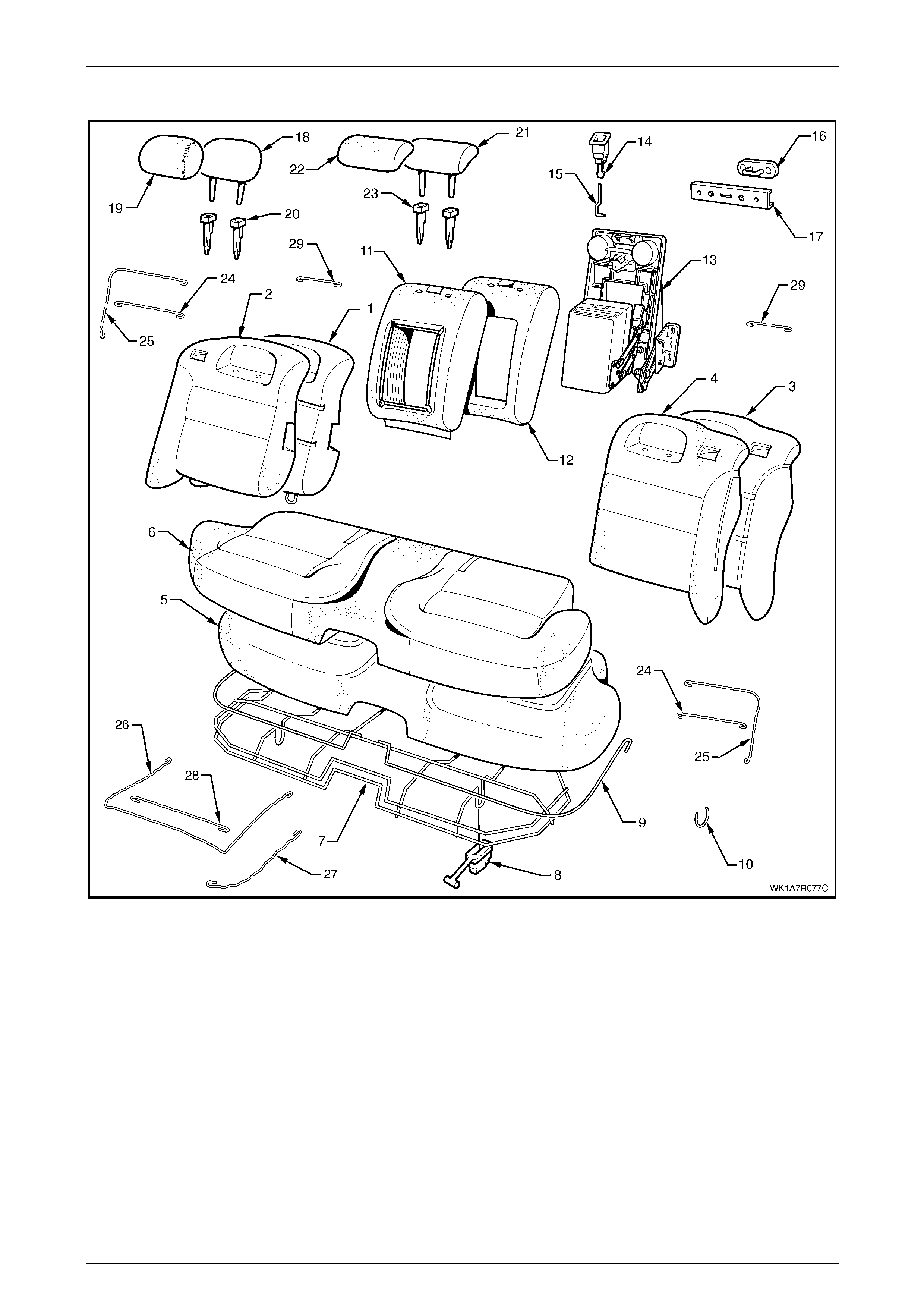
Seat Assemblies Page 1A7–317
Page 1A7–317
Rear Seat Type 7
Figure 1A7 – 186

Seat Assemblies Page 1A7–318
Page 1A7–318
Legend
1 Rear Seat-back Pad and Frame Assembly, RH
2 Rear Seat-back Cover, RH
3 Rear Seat-back Pad and Frame Assembly, LH
4 Rear Seat-back Cover, LH
5 Rear Seat Cushion Pad
6 Rear Seat Cushion Cover
7 Rear Seat Cushion Frame, Two Places
8 Rear Seat Cushion Release Handle, Two Places
9 Rear Seat Cushion Cover Ret ai ner W i re
10 Hog Ring
11 Rear Seat-back Cent re Cover
12 Rear Seat-back Cent re Pad
13 Rear Seat-back Centre Tray and Armrest Assem bl y ∗
∗∗
∗
14 Rear Seat-back Centre Release Button
15 Release Butt on Rod
16 Rear Seat-back Cent re Lock St riker
17 Rear Seat-back Cent re Striker Cover
18 Rear Seat-back Head Restraint Pad Assembly, One Place
Each Side
19 Rear Seat-back Head Rest rai nt Cover, One Pl ace Each Side
20 Rear Seat-back Head Restraint Sleeve, Two Places Each
Side
21 Rear Seat-back Cent re Head Restraint Pad
22 Rear Seat-back Centre Head Restraint Cover
23 Centre Head Rest rai nt Sleeve, Two Places
24 Rear Seat-back Inner Horizontal Groove Retainer Wire
25 Rear Seat-back Outer Groove Retainer Wire
26 Rear Seat Cushion Cover Outer Retainer W i re, Two Places
27 Rear Seat Cushion Cover Inner Retainer Wi re, Two Plac es
28 Rear Seat Cushion Cover Front Retainer Wi re, Two Plac es
29 Rear Seat-back Cushion Head Restraint Retainer Wire
∗
∗∗
∗ Refer to Figure 1A7 – 189 for a breakdown of the rear seat-back centre tray and armrest assembly.
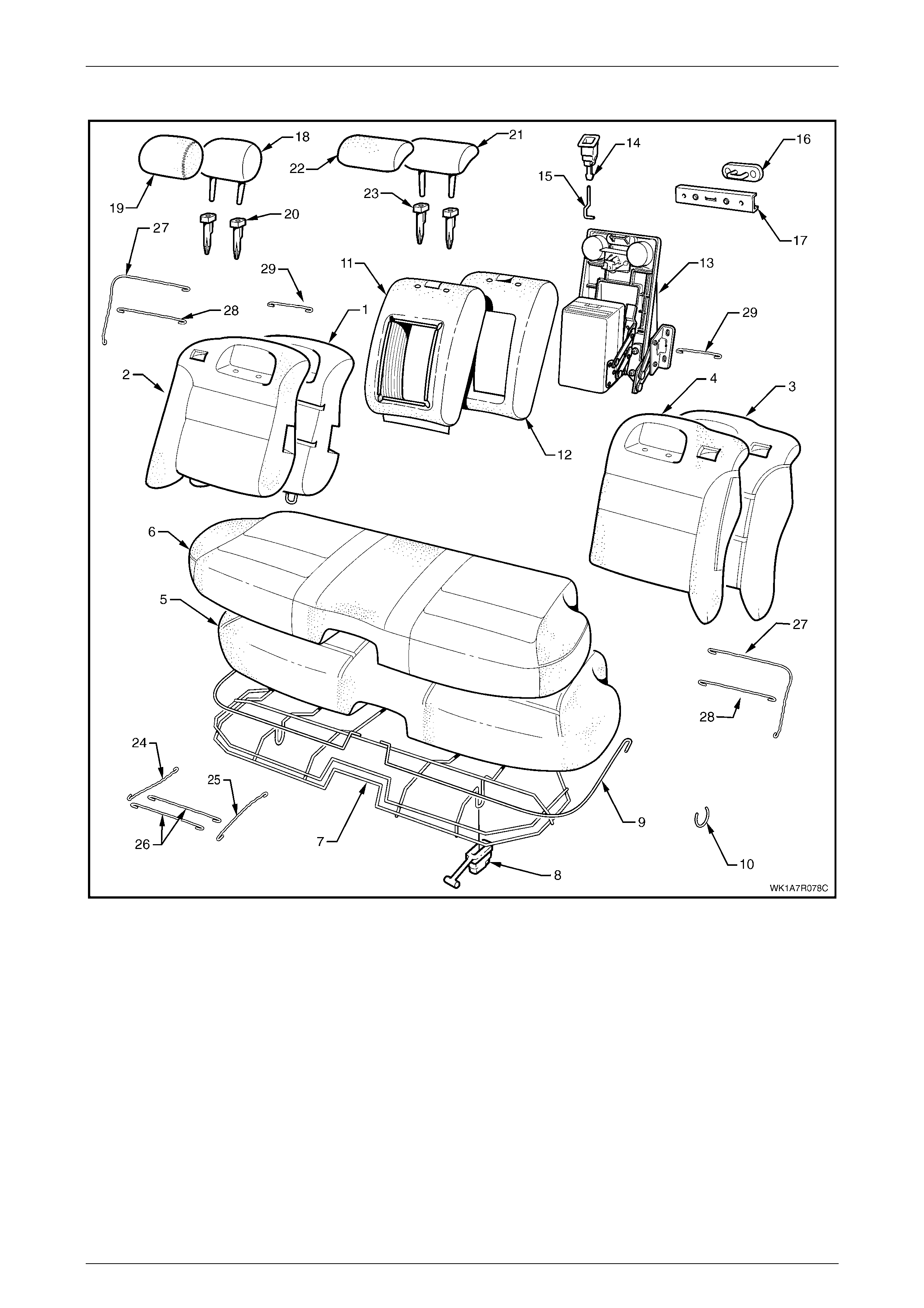
Seat Assemblies Page 1A7–319
Page 1A7–319
Rear Seat Type 8
Figure 1A7 – 187

Seat Assemblies Page 1A7–320
Page 1A7–320
Legend
1 Rear Seat-back Pad and Frame Assembly, RH
2 Rear Seat-back Cover, RH
3 Rear Seat-back Pad and Frame Assembly, LH
4 Rear Seat-back Cover, LH
5 Rear Seat Cushion Pad
6 Rear Seat Cushion Cover
7 Rear Seat Cushion Frame
8 Rear Seat Cushion Release Handle, Two Places
9 Rear Seat Cushion Cover Ret ai ner Wi re, Two Places
10 Hog Ring
11 Rear Seat-back Cent re Cover
12 Rear Seat-back Cent re Pad
13 Rear Seat-back Centre Tray and Armrest Assem bl y ∗
∗∗
∗
14 Rear Seat-back Centre Release Button
15 Release Butt on Rod
16 Rear Seat-back Cent re Lock St riker
17 Rear Seat-back Cent re Striker Cover
18 Rear Seat-back Head Restraint Pad Assembly, One Place
Each Side
19 Rear Seat-back Head Rest rai nt Cover, One Pl ace Each Side
20 Rear Seat-back Head Restraint Sleeve, Two Places Each
Side
21 Rear Seat-back Cent re Head Restraint Pad Assembly
22 Rear Seat-back Centre Head Restraint Cover
23 Rear Seat-back Centre Head Restraint Sleeve, Two Places
24 Rear Seat Cushion Cover Outer Retainer W i re, Two Places
25 Rear Seat Cushion Cover I nner Retainer Wi re, Two Places
26 Rear Seat Cushion Cover Front Retai ner Wi re, Four Plac es
27 Rear Seat-back Outer Groove Retainer Wire
28 Rear Seat-back Cushion Inner Horizontal Groove Retainer
Wire
29 Rear Seat-back Cushion Head Restraint Retainer Wire
* Refer to Figure 1A7 – 188 for a breakdown of the rear seat-back centre tray and armrest assembly.
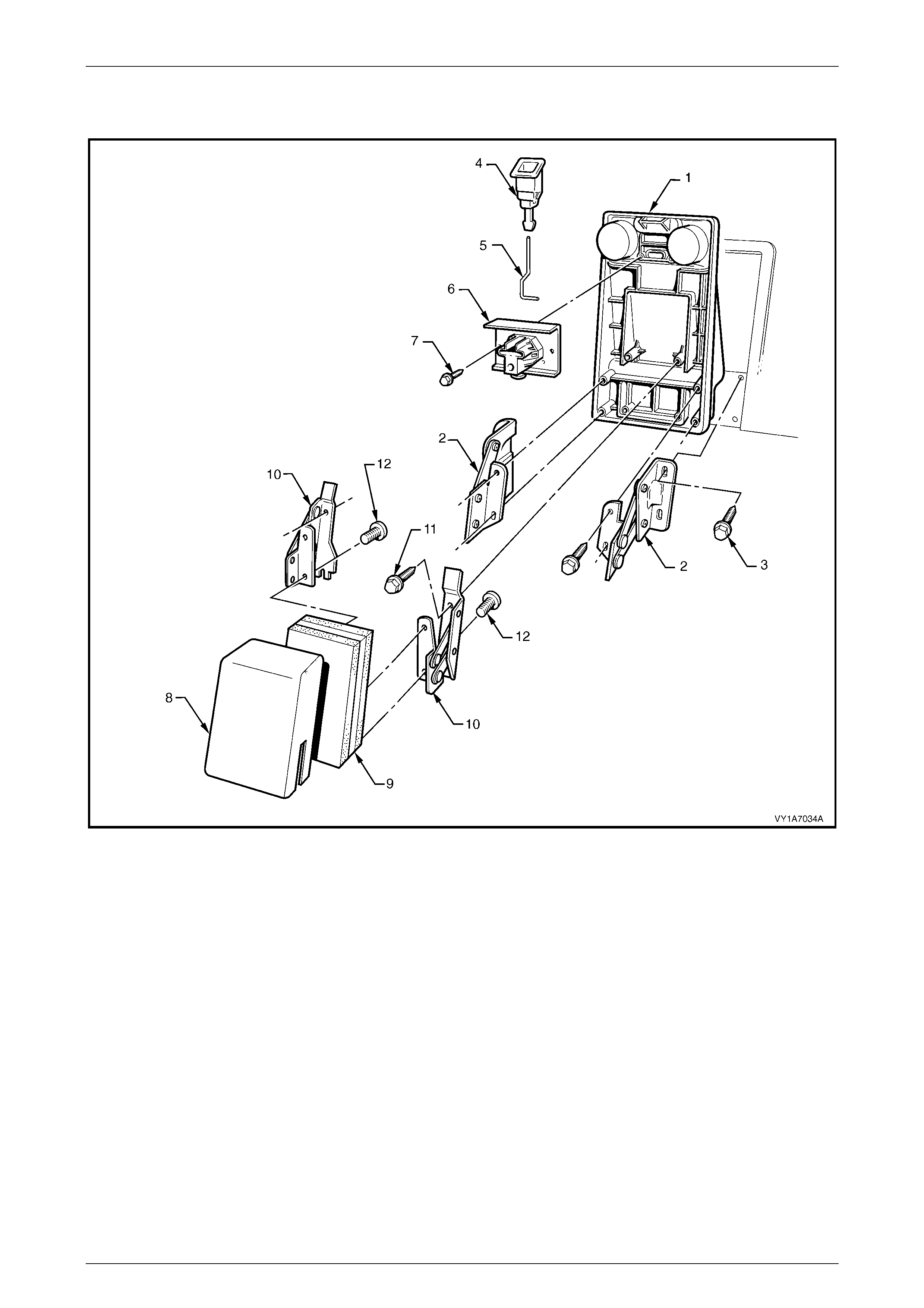
Seat Assemblies Page 1A7–321
Page 1A7–321
Rear Seat-back Centre Tray and Armrest Assembly without Compartment
Figure 1A7 – 188
Legend
1 Rear Seat-back Centre Tray
2 Rear Seat-back Cent re Tray Hinge
3 Hinge Rear Seat-back Cent re Bolt, Four Places
4 Rear Seat-back Centre Release Button
5 Release Butt on Rod
6 Rear Seat-back Cent re Lock Actuator
7 Lock Actuator Bolt, Two Places
8 Centre Armrest Cover
9 Centre Armrest Pad
10 Centre Armrest Assembly Hi nge
11 Centre Armrest Hinge Bolt, Four Places
12 Centre Armrest Hinge Screw, Four Places
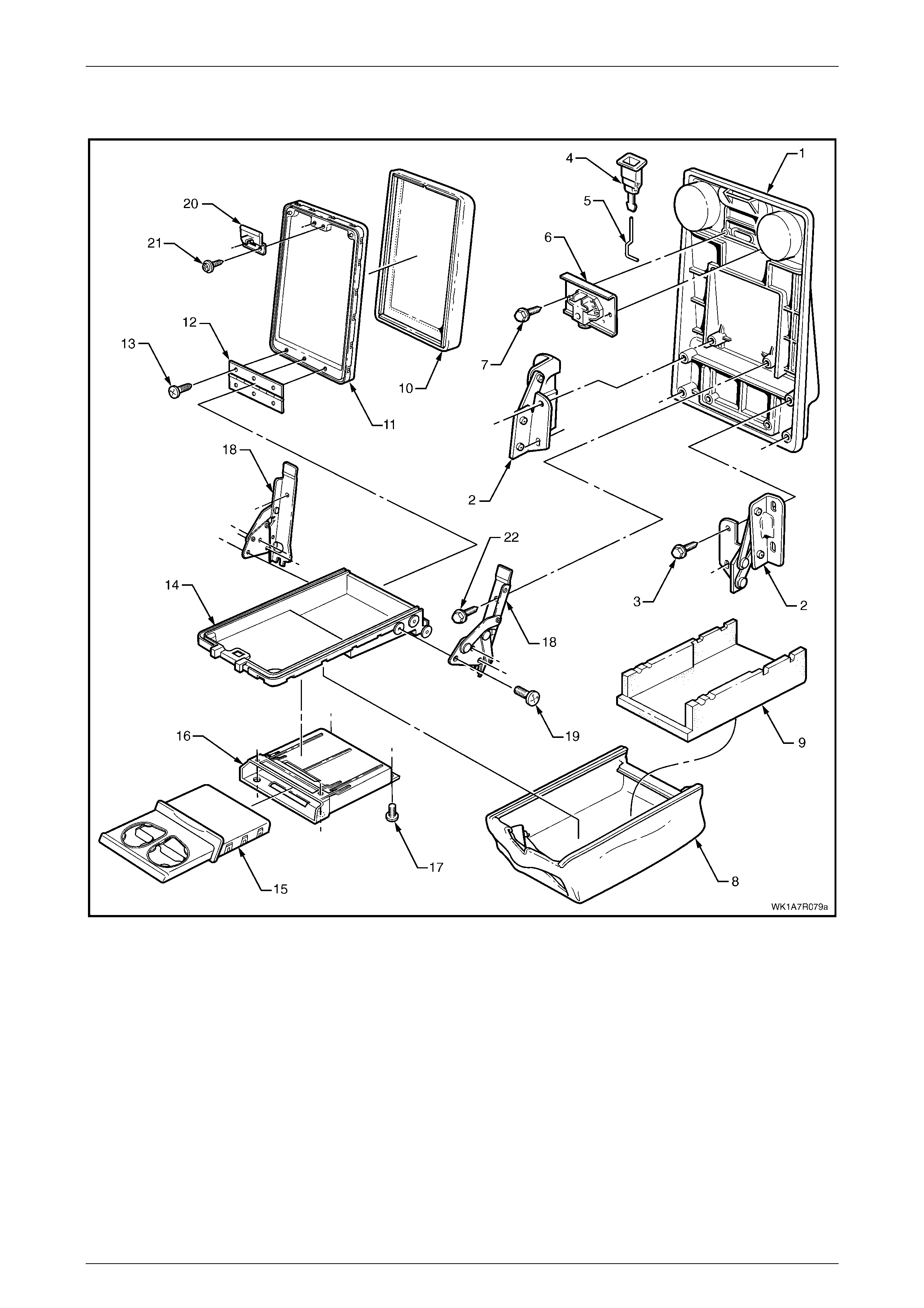
Seat Assemblies Page 1A7–322
Page 1A7–322
Rear Seat-back Centre Tray and Armrest Asse mbly with Compartment
Figure 1A7 – 189
Legend
1 Rear Seat-back Centre Tray
2 Rear Seat-back Cent re Tray Hinge
3 Rear Seat-back Centre Hinge Bolt, Four Places
4 Rear Seat-back Centre Release Button
5 Release Butt on Rod
6 Rear Seat-back Cent re Lock Actuator
7 Lock Actuator Bolt, Two Places
8 Centre Armrest Cover
9 Centre Armrest Pad
10 Centre Armrest Lid Cover
11 Centre Armrest Lid
12 Centre Armrest Lid Hinge
13 Centre Armrest Lid Hinge Screw, Six Places
14 Centre Armrest Deposit B ox
15 Centre Armrest Cup Holder
16 Centre Armrest Cup Holder Housing
17 Centre Armrest Cup Holder Housing Screw, Four Pl aces
18 Centre Armrest Assembly Hi nge
19 Centre Armrest Hinge Screw, Six Plac es
20 Centre Armrest Lid Latch
21 Centre Armrest Lid Latch Screw, Two Places
22 Centre Armrest Ass embly Hinge Bolt, Four Places
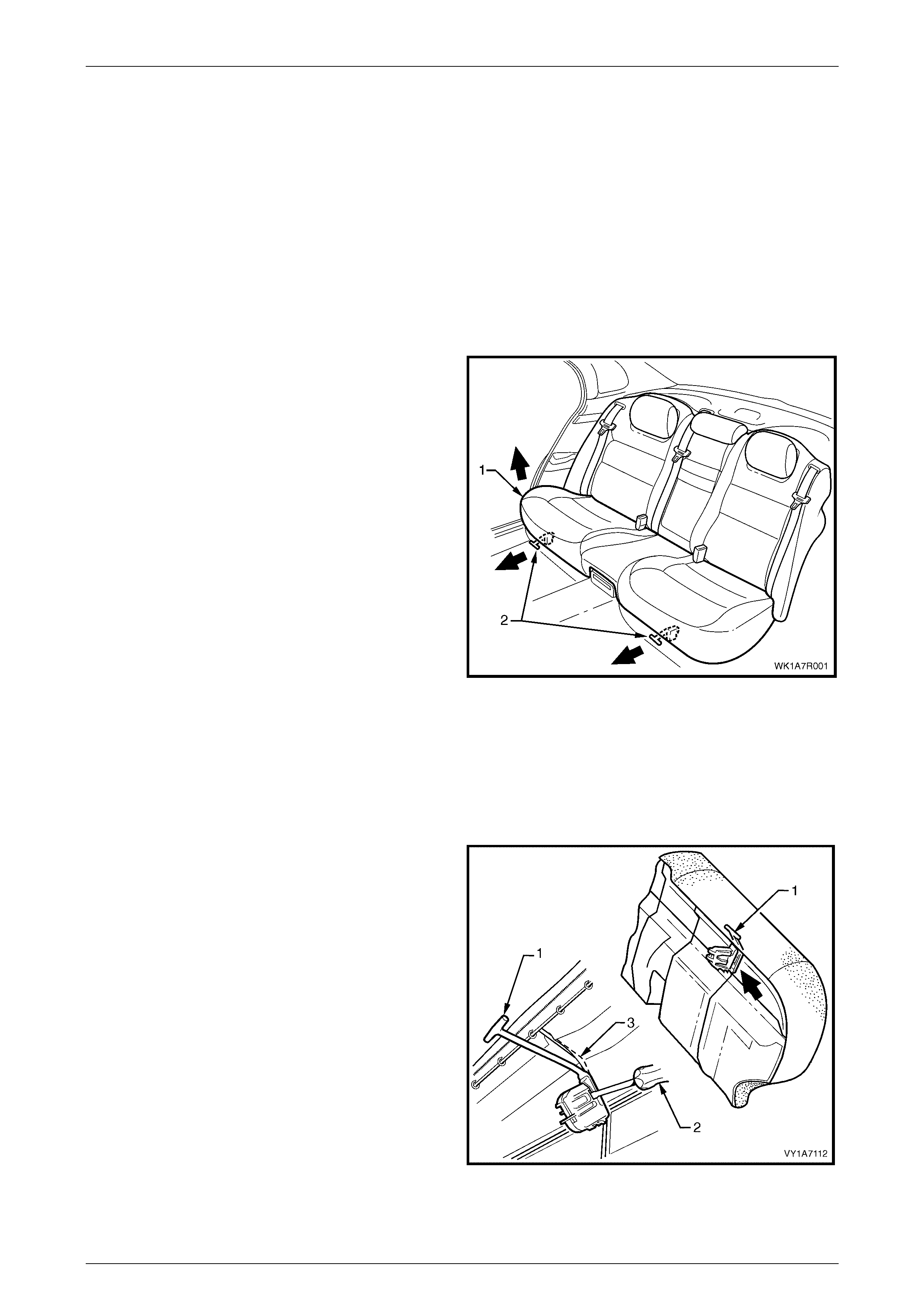
Seat Assemblies Page 1A7–323
Page 1A7–323
7.2 Rear Seat Cushion Assembly
LT Section No. – 14-330
Remove
NOTE
If fitted with a DVD, use care when removing the
rear seat cushion to avoid damage to the DVD
control panel cover located under the rear seat
cushion.
1 Lift the front of the rear seat cushion assembly (1)
slightly, to gain access to the rear seat cushion
release handles (2).
2 From either the left or the right side of the seat, pull
the release handle T-piece horizontally forwards, while
at the same time lifting the front of the rear seat
cushion until the lock mechanism is released.
3 Repeat step 2 for the opposite side of the seat.
4 Remove the rear seat cushion assembly.
Figure 1A7 – 190
Disassemble
Rear Seat Cushion Release Handle
Remove
1 Remove the rear seat cushion release handle (1) by
inserting a screwdriver (2) to disengage the retaining
lugs.
2 Slide the release handle off the rear seat cushion wire
frame (3).
Figure 1A7 – 191
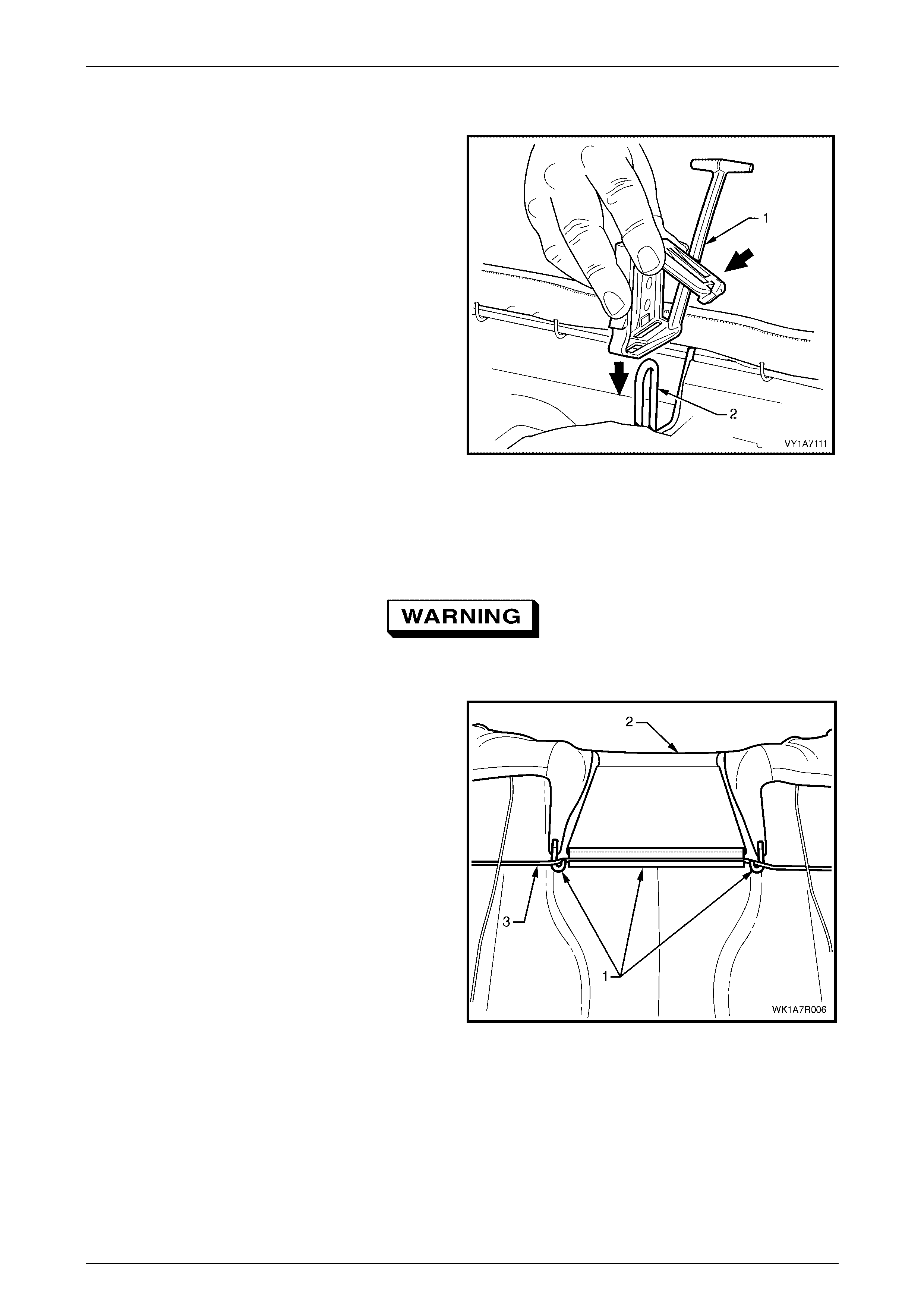
Seat Assemblies Page 1A7–324
Page 1A7–324
Reinstall
1 Slide the rear seat cushion release handle (1) onto the
rear seat cushion wire frame (2) and close the cover
so that it will lock into position on the frame.
Figure 1A7 – 192
Rear Seat Cushion Frame
Remove
Safety glasses and work gloves must be worn
at all times when removing the hog rings.
1 With the rear seat cushion asse mbly upside down,
follow the procedures below for the appropriate rear
seat type assembly .
a For rear seat Types 7 and 8, unclip the three
retainers (1) attaching the rear seat cushion
cover (2) to the rear seat cushion frame (3).
b For rear seat Types 1 to 6, proceed to step 2.
Figure 1A7 – 193
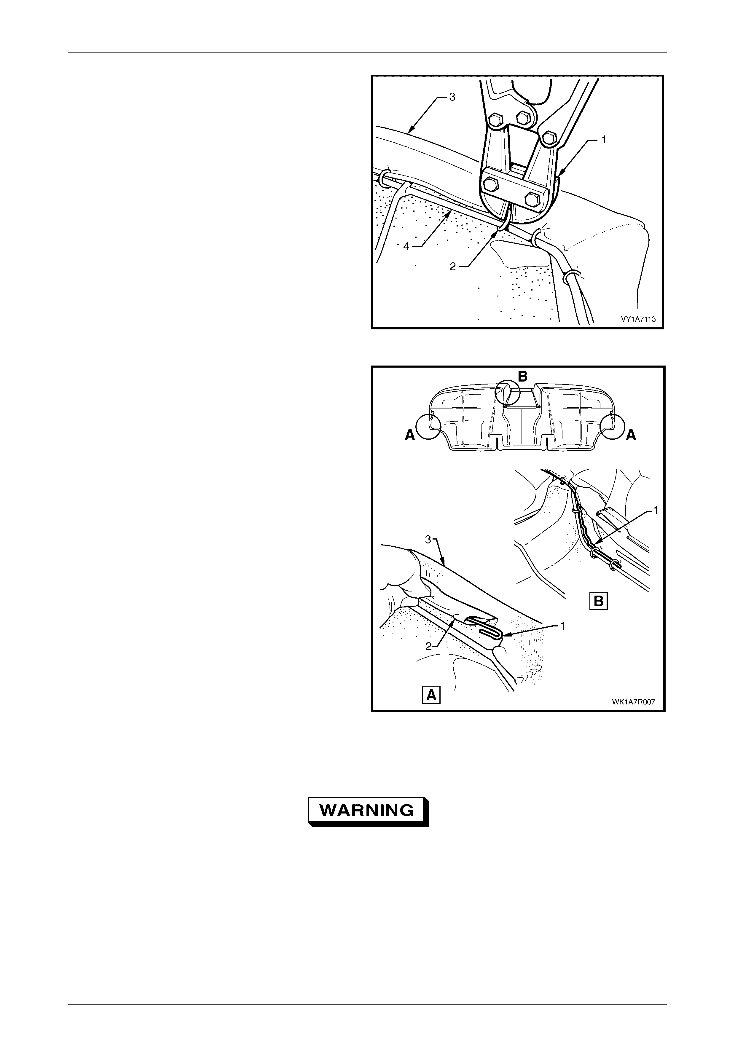
Seat Assemblies Page 1A7–325
Page 1A7–325
2 Use bolt cutters or side cutters (1) to remove the hog
rings (2) attaching the cover and pad assembly (3) to
the frame (4).
• 51 places for the Surebond rear seat Type 1
cushion.
• 54 places for the hook and loop rear seat Type 4
cushion.
• 59 places for the conventional Pull-down rear
seat cushion, all other Ty pes.
NOTE
Care must be taken when removing the hog
rings not to damage the cushion cover. All hog
rings will be destroyed during this operation and
must be replaced.
3 Remove the frame from the rear seat cushion
assembly.
Figure 1A7 – 194
4 If required, remove the retaining wire (1) from the
casing (2) attached to the cushion cover assembly (3),
refer, View A only for rear seat Types 1 to 6 and Views
A and B for rear seat Types 7 and 8.
NOTE
For rear seat Types 7 and 8, the retaining wire is
in two pieces with the break in the wire across
the front of the seat.
Figure 1A7 – 195
Reinstall
Safety glasses and work gloves must be worn
at all times when working with hog rings.
NOTE
All hog rings must be replaced when reinstalling
the rear seat cushion frame.
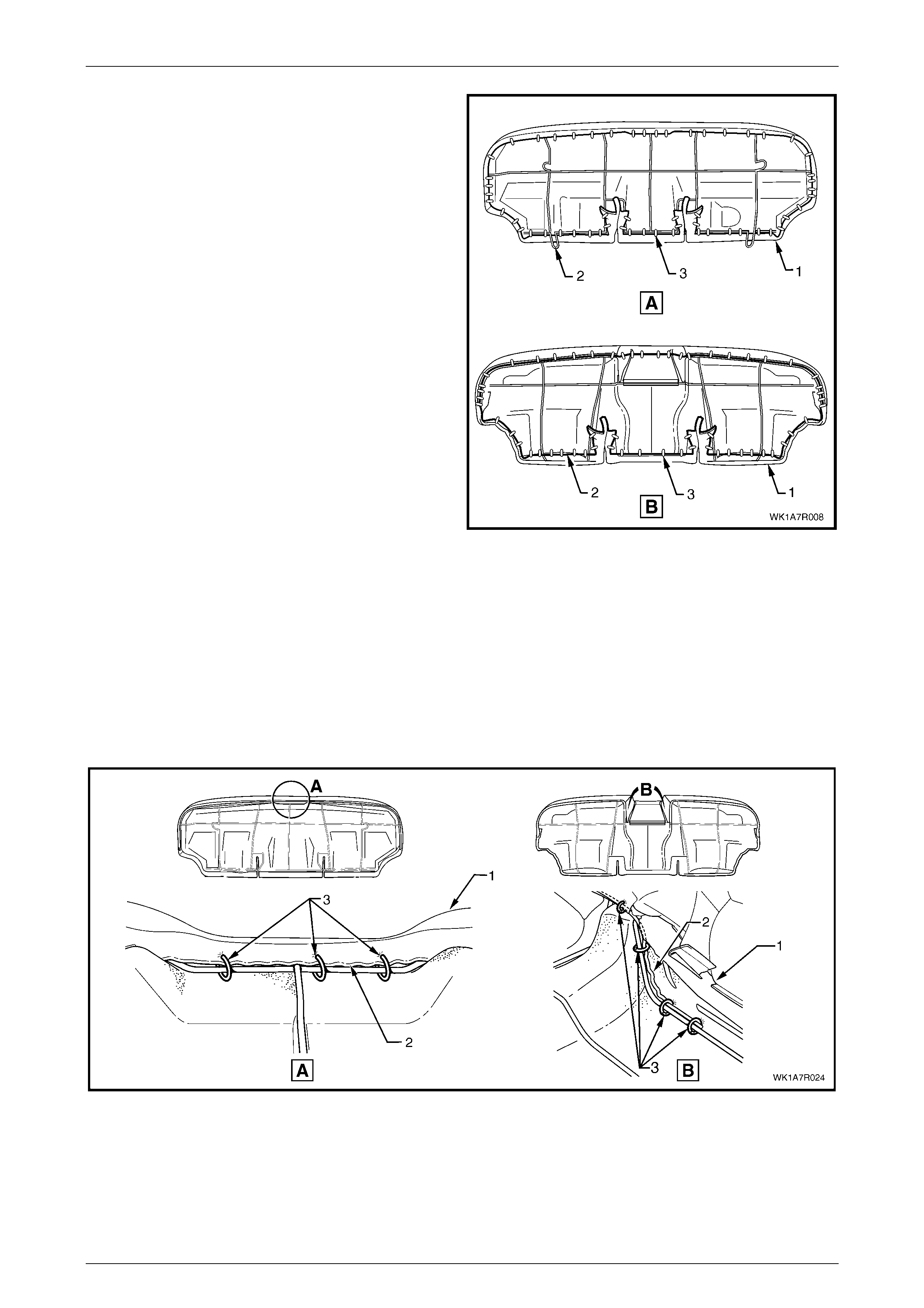
Seat Assemblies Page 1A7–326
Page 1A7–326
Using the following sequence of operations, align the rear
seat cushion cover and pad assembly (1) to the rear seat
cushion frame (2) and attach the hog rings (3).
• 51 places for the Surebond rear seat cushion,
rear seat Type 1.
• 54 places for the hook and loop rear seat cushion,
rear seat Type 4.
• 59 places for the conventional pull down rear seat
cushion, all other rear seat Types.
Figure 1A7 – 196
NOTE
For rear seat Types 7 and 8, the rear seat
cushion cover retaining wire is a two-piece wire.
1 Starting at the front, centre of the rear seat cushion cover assembly (1), attach the wire retainer (2) with the
appropriate number of hog rings (3), refer to Figure 1A7 – 197.
a Three places for rear seat Types 1 to 6, View A.
b Four places for rear seat Types 7 and 8, View B, each side.
Figure 1A7 – 197
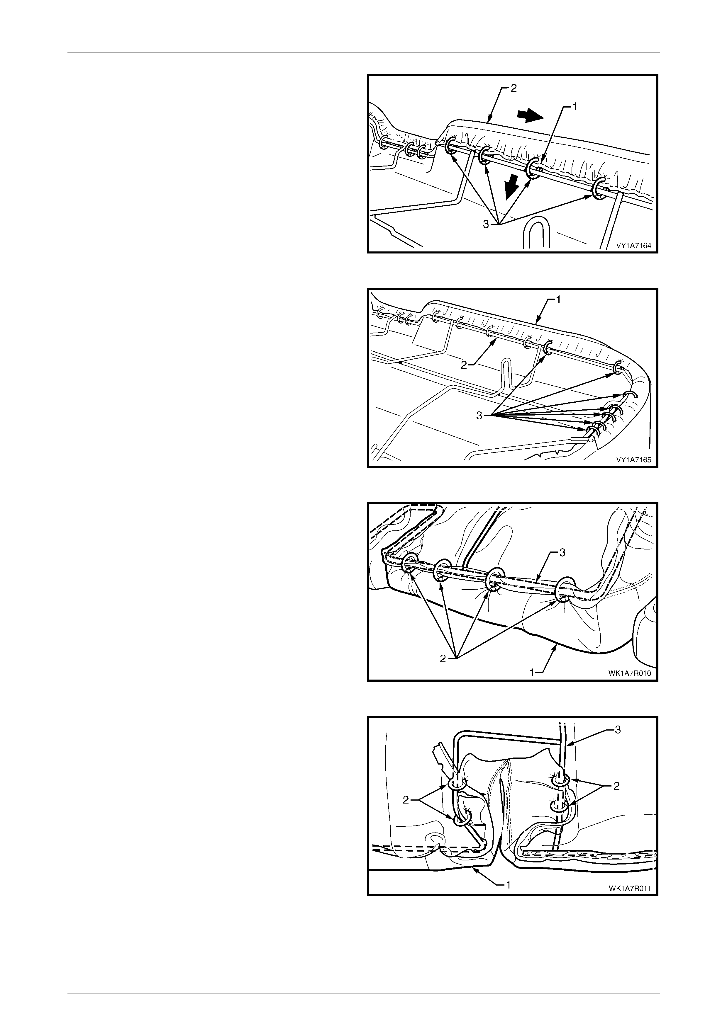
Seat Assemblies Page 1A7–327
Page 1A7–327
2 Working from the centre outward, attach the wire
retainer (1), while pulling the cover assembly (2) tight
and attach with four hog rings (3).
3 Repeat this process in the opposite direction working
from the centre outward.
Figure 1A7 – 198
4 Continue attaching the cover assembly (1) to the
frame (2), by pulling the cover tight and atta ch with
seven hog rings (3).
5 Repeat this process in the opposite direction.
Figure 1A7 – 199
6 Pull the rear of the cover assembly (1) tight and attach
the centre with four hog rings (2) to the centre of the
wire frame (3).
Figure 1A7 – 200
7 Pull the cushion cover assembly (1) tight into the
seatbelt slot at the rear and attach with four hog rings
(2) to the wire frame (3).
8 Repeat this process for the opposite seatbelt slot.
Figure 1A7 – 201
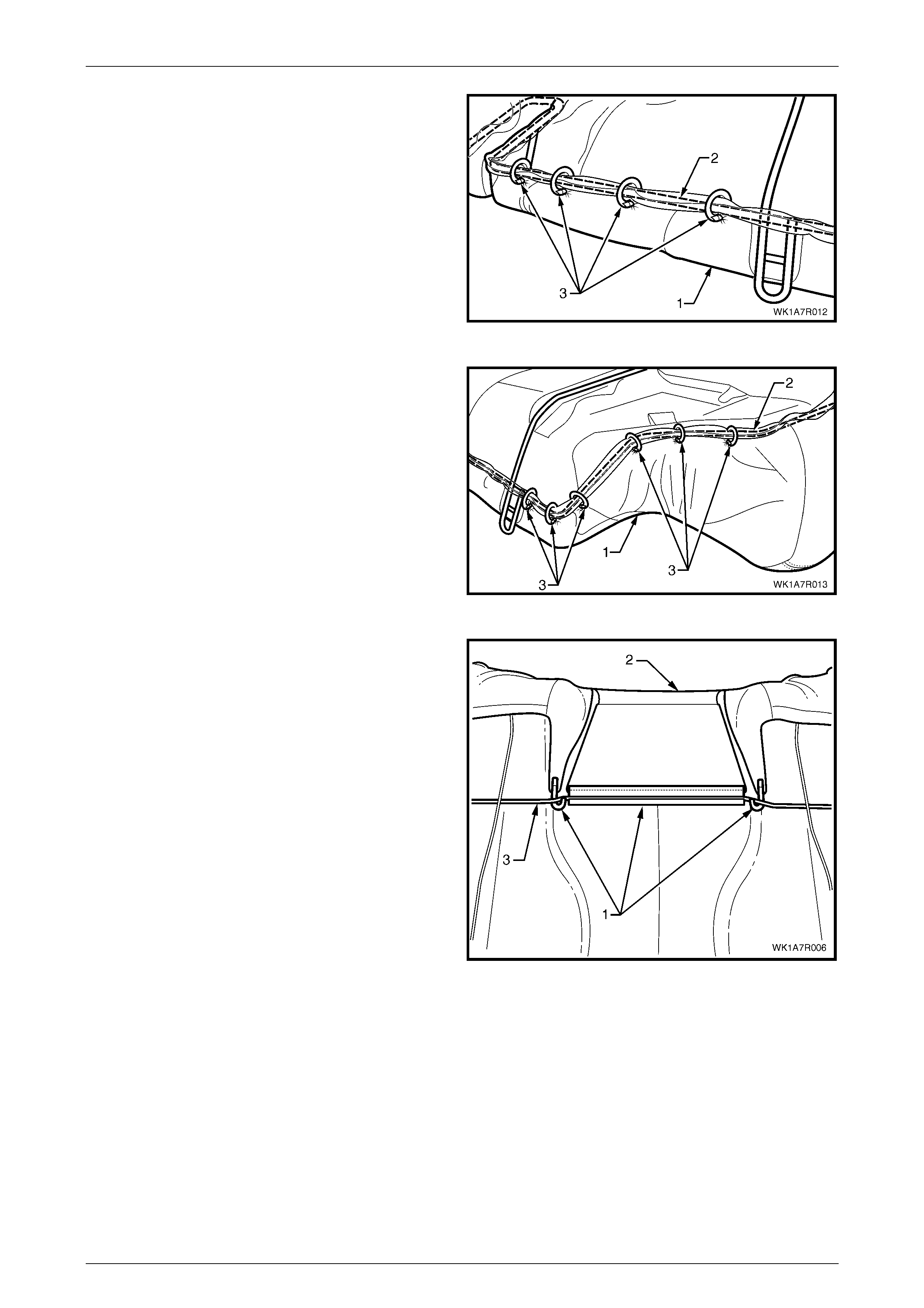
Seat Assemblies Page 1A7–328
Page 1A7–328
9 Working outward from the seatbelt slot, continue
attaching the cover assembly (1) to the frame (2), by
pulling the cover tight and attach with four hog rings
(3).
10 Repeat this process in the opposite direction.
Figure 1A7 – 202
11 At the rear corner continue attaching the cover
assembly (1) to the frame (2), by pulling the cover
tight, up and around the corner and attach with six
hog rings (3).
12 Repeat this process for the opposite corner.
NOTE
The cover should be smooth and without
creases. If this is not the case, extra hog rings
should be used to pull the cover into place.
Figure 1A7 – 203
13 For rear seat Types 7 and 8, re install the three
retainers (1) attaching the rear seat cushion cover (2)
to the rear seat cushion frame (3).
Figure 1A7 – 204
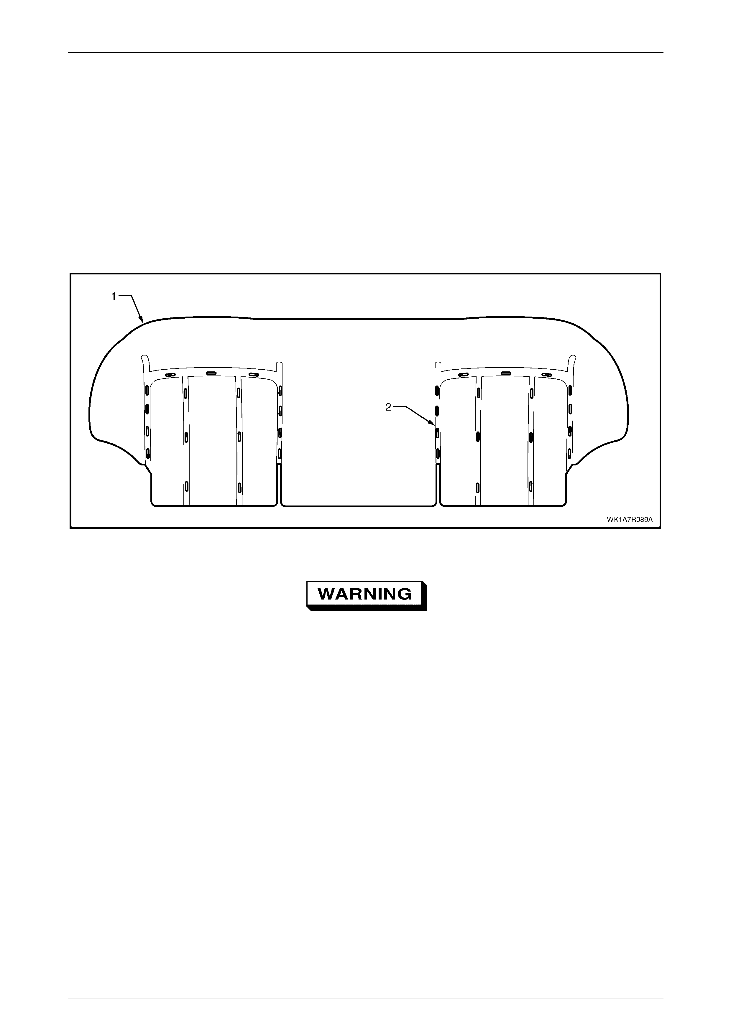
Seat Assemblies Page 1A7–329
Page 1A7–329
Cushion Cover Assembly
Rear Seat Type 1
Surebond cushion cover and pad assembly are glued together as an assembly and are not serviced as separate
components. If either the pad or the cover requires replacement, both will have to be replaced as a combined unit.
Rear Seat Type 2 and 5
Remove
The cloth rear seat cushion cover for the rear seat Type 2 and 5 cushion pad (1) is attached with approximately 34 hog
rings (2), in the locations shown, refer to Figure 1A7 – 205.
Figure 1A7 – 205
Safety glasses and work gloves must be worn
at all times when removing the hog rings.
NOTE
Care must be taken when removing the hog rings
not to damage the cushion cover. All hog rings
will be destroyed during this operation and must
be replaced.
Using the following sequence of operations, cut the hog rings as they are revealed using bolt cutters or side cutters.
1 If required, remove the rear seat cushion frame, refer to Rear Seat Cushion Frame.
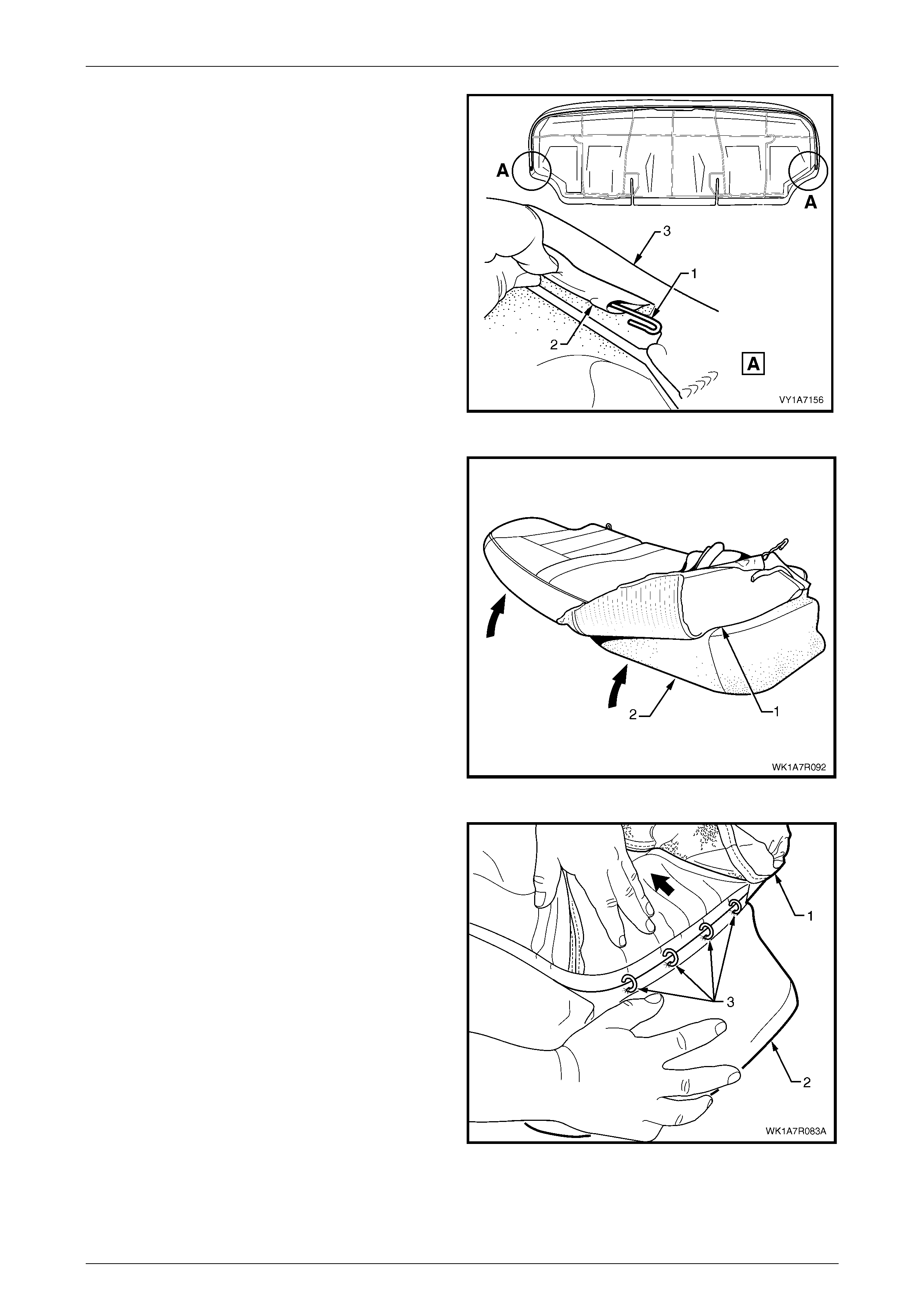
Seat Assemblies Page 1A7–330
Page 1A7–330
2 If required, remove the retaining wire (1) from the
casing (2) attached to the cushion cover assembly (3).
Figure 1A7 – 206
3 Fold the rear corner of the rear seat cushion cover (1)
over the seat cushion pad (2), then fold the front
corner of the cover up.
Figure 1A7 – 207
4 From the outer edge, continue to fold the cushion
cover (1) back while holding the cushion pad (2)
revealing the four hog rings (3) attaching the outer
retaining wire to the pad and cut the hog rings.
Figure 1A7 – 208
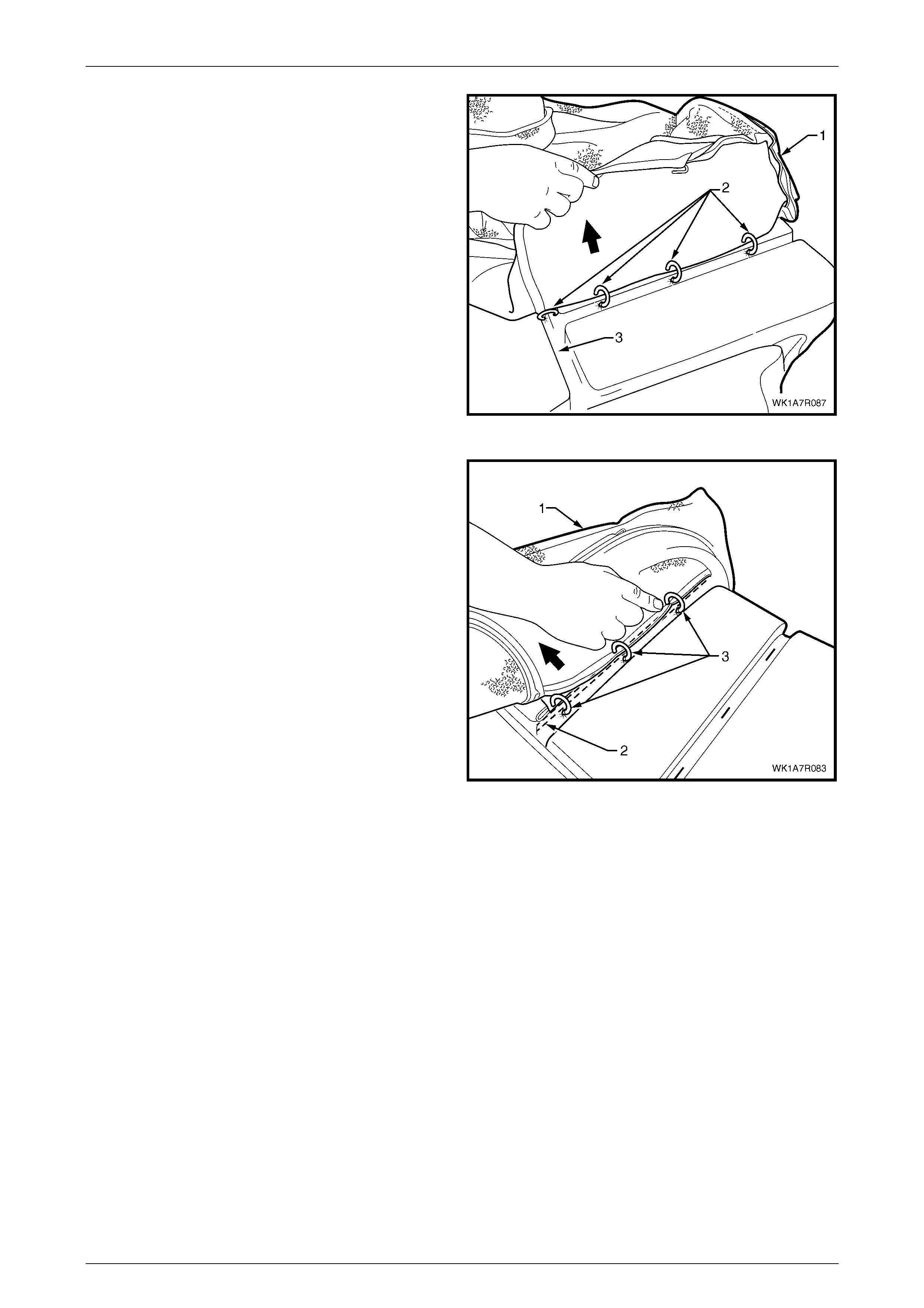
Seat Assemblies Page 1A7–331
Page 1A7–331
5 Working towards the centre of the seat cushion,
carefully fold back the cover (1) revealing the hog
rings (2) attaching the inner and front retaining wires to
the pad. Cut these and continue folding the cover back
until all hog rings in the corresponding grooves (3)
have been removed.
Figure 1A7 – 209
6 Continue to fold the cushion (1) over towards the
centre and from the front of the rear seat cushion (2).
Cut the hog rings (3), three places, attaching the inner
retaining wire to the pad.
7 Repeat the process for the centre groove.
8 Repeat the process for the other side of the rear seat
cushion.
9 Remove the cushion cover from the cushion.
Figure 1A7 – 210
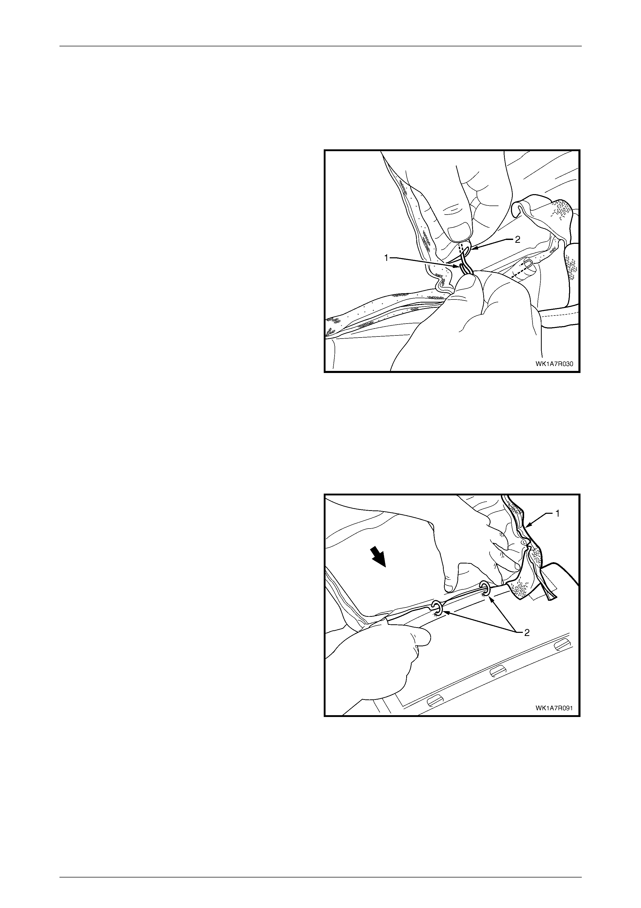
Seat Assemblies Page 1A7–332
Page 1A7–332
NOTE
The cushion cover has ten retaining wires that
align the cushion cover to the cushion pad and
are used to hook the hog rings to. These will
need to be removed from the cover if it is to be
replaced.
10 If required, remo ve the retaining wire (1) from the
casing (2) and repeat for the re maining nine plac es.
Figure 1A7 – 211
Reinstall
Referring to Figure 1A7 – 205 showing the hog ring locations, reinstall the rear seat cushion cover using the following
sequence of operations, attaching the hog rings with hog ring pliers.
1 If required, reinstall the retaining wire (1) into the casing (2) ten locations in the cushion cover assembly, refer to
Figure 1A7 – 211.
2 Beginning on one side of the cushion, pos itio n the
cover (1) into the inner correspondin g groov e.
NOTE
Ensure the cushion cover aligns to all the
grooves in the cushion pad before attaching the
cover with hog rings.
3 Starting at the rear and working towards the front,
attach four hog rings (2) using hog ring pliers.
Figure 1A7 – 212
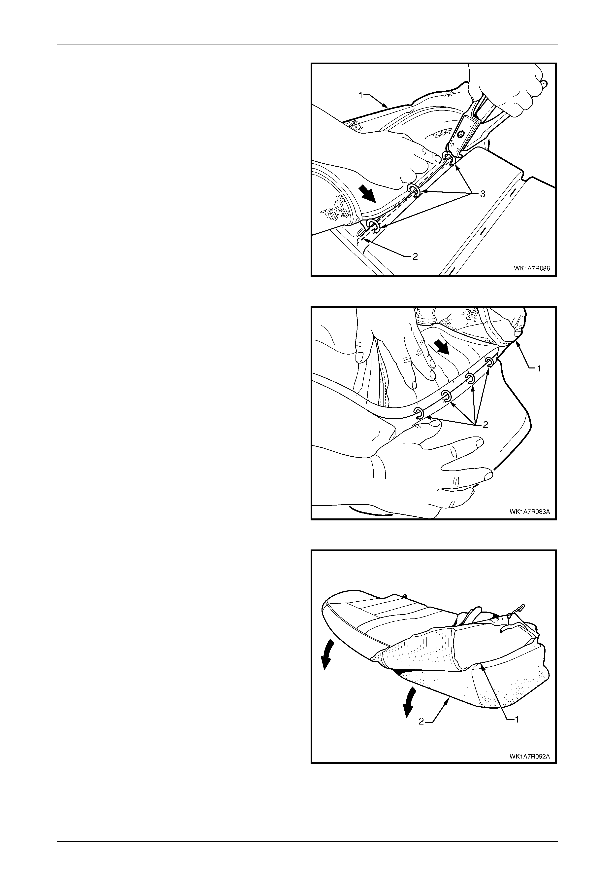
Seat Assemblies Page 1A7–333
Page 1A7–333
4 Continue working towards the outside edge of the
cushion, fold the cushion cover (1) into the centre
corresponding groove (2) and attach the cover with
three hog rings (3).
5 Repeat for the other centre corresponding groove.
6 Position the cover into the front corresponding cushion
groove and attach with three hog rings using the same
method as for the centre grooves.
Figure 1A7 – 213
7 Working along the side of the rear seat cushion,
position the cover (1) into the outer corresponding
groove and attach four hog rings (2).
8 Repeat the process for the opposite side of the rear
seat cushi on cov er.
Figure 1A7 – 214
9 Fold the rear seat cushion cover (1) over the corners
of the cushion pad (2).
10 Pull the rear seat cushion cover up over the rear seat
cushion ensuring that the cushion cover is fitted neatly
into all corners and cont our s of the rear seat cushion.
Figure 1A7 – 215
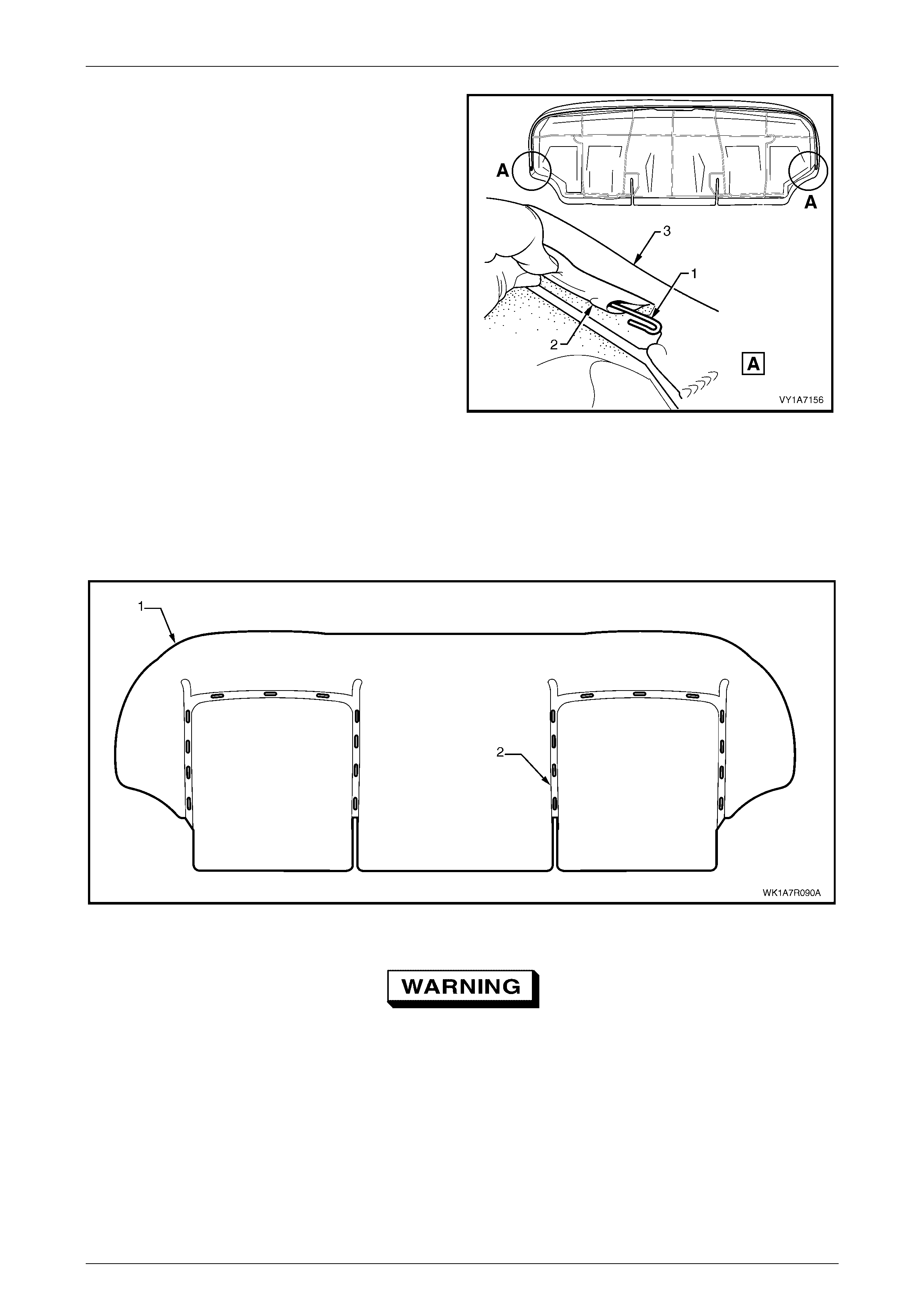
Seat Assemblies Page 1A7–334
Page 1A7–334
11 If removed, reinstall the retaining wire (1) from the
casing (2) attached to the cushion cover assembly (3).
12 Refit the rear seat cushion frame, refer to Rear Seat
Cushion Frame.
Figure 1A7 – 216
Rear Seat Type 3 and 6
Remove
The leather rear seat cushion cover for rear seat Types 3 and 6 cushion pad (1) is, attached to the cushion with
approximately 28 hog rings (2) in the locations shown, refer to Figure 1A7 – 217.
Figure 1A7 – 217
Safety glasses and work gloves must be worn
at all times when removing the hog rings.
NOTE
Care must be taken when removing the hog rings
not to damage the cushion cover. All hog rings
will be destroyed during this operation and must
be replaced.
Using the following sequence of operations, cut the hog rings as they are revealed using bolt cutters or side cutters.
1 If required, remove the rear seat cushion frame, refer to Rear Seat Cushion Frame.

Seat Assemblies Page 1A7–335
Page 1A7–335
2 If required, remove the retaining wire (1) from the
casing (2) attached to the cushion cover assembly (3).
Figure 1A7 – 218
3 Pull the rear corner of the rear seat cushion cover (1)
over the seat cushion pad (2) and then pull the front
corner of the cover up.
Figure 1A7 – 219
4 Fold the cushion cover (1) towards the centre of the
cushion while holding the cushion pad (2) revealing
the four hog rings (3) and cut to remove.
Figure 1A7 – 220
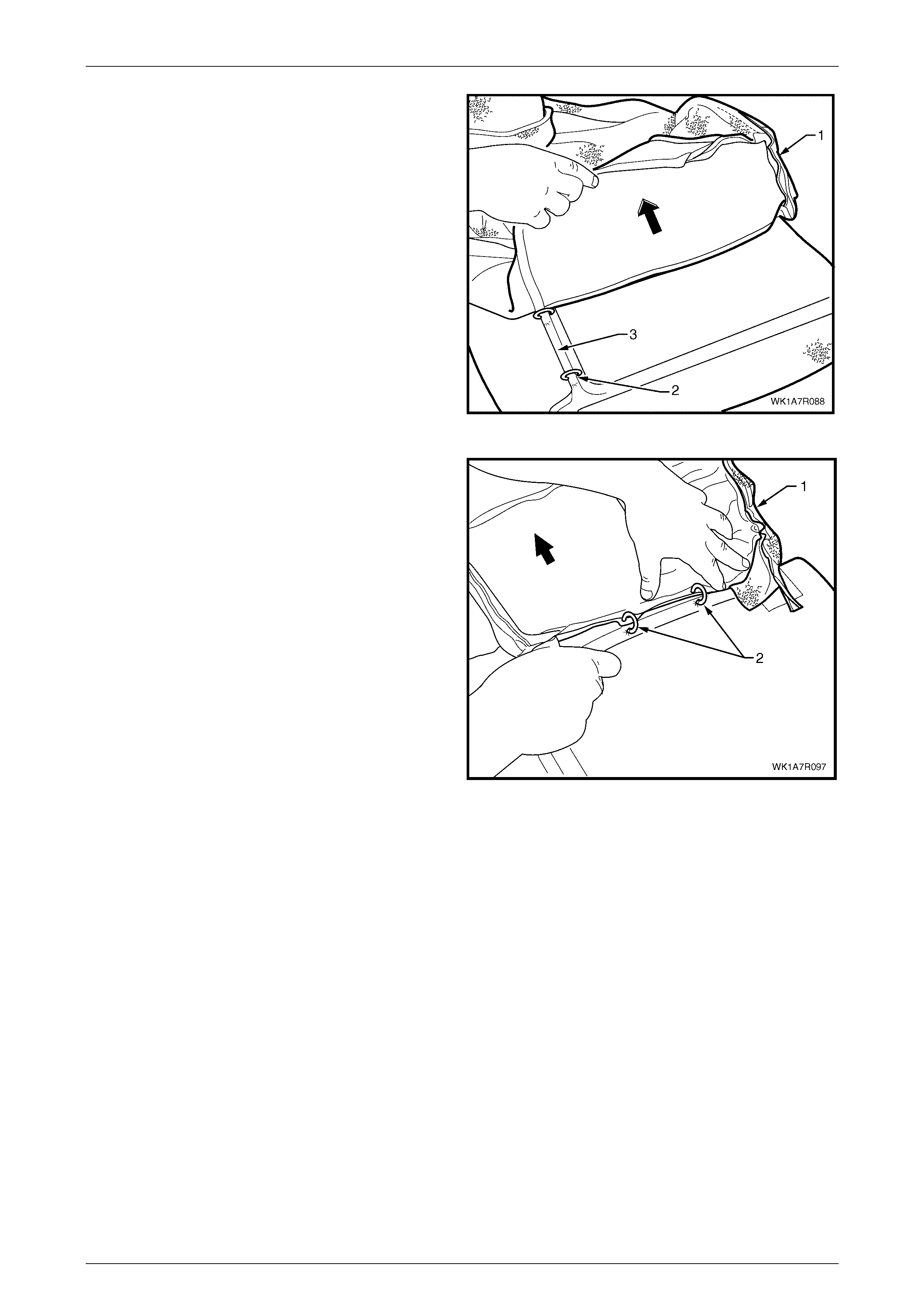
Seat Assemblies Page 1A7–336
Page 1A7–336
5 Working towards the centre of the rear seat cushion,
carefully fold back the cover (1) revealing the outer
hog ring (2), cut this and continue folding the cover
back until a ll th ree hog rings in the correspon ding
groove (3) have been removed.
Figure 1A7 – 221
6 Continue to fold the cushion over towards the centre
and from the rear of the seat cushion, cut the hog
rings (2), in four places, while working towards the
front.
7 Repeat steps 3 to 6 for the other side of the rear seat
cushion.
8 Remove the cushion cover from the cushion.
Figure 1A7 – 222
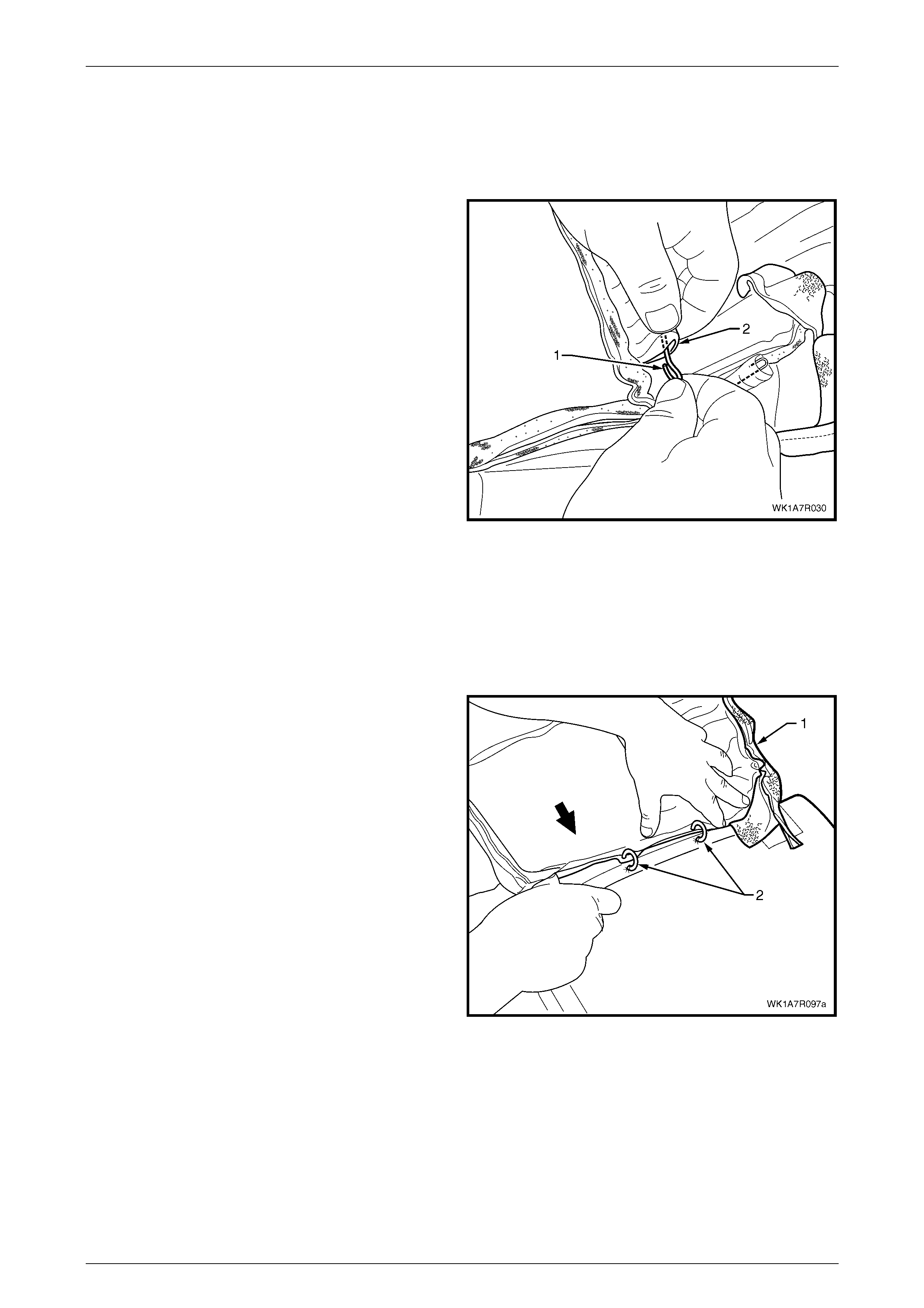
Seat Assemblies Page 1A7–337
Page 1A7–337
NOTE
The cushion cover has six retaining wires that
align to the grooves in the cushion pad and are
used to hook the hog rings to. These will need to
be removed from the cover if it is to be replaced.
9 If required, remove the retaining wire (1) from the
casing (2) and repeat for the remaining five places.
Figure 1A7 – 223
Reinstall
Referring to Figure 1A7 – 217 showing the hog ring locations, install the rear seat cushion cover using the following
sequence of operations, attaching the hog rings with hog ring pliers.
1 If required, reinstall the retaining wire (1) into the casing (2), six places, in the cushion cover assembly, refer to
Figure 1A7 – 223.
2 Beginning on one side of the cushion, pos itio n the
cover (1) into the inner corresponding groove. Starting
at the rear and working towards the front, attach with
four hog rings (2) using hog ring pliers.
NOTE
Ensure the cushion cover aligns to all the
grooves in the cushion pad before attaching the
cover with hog rings.
Figure 1A7 – 224
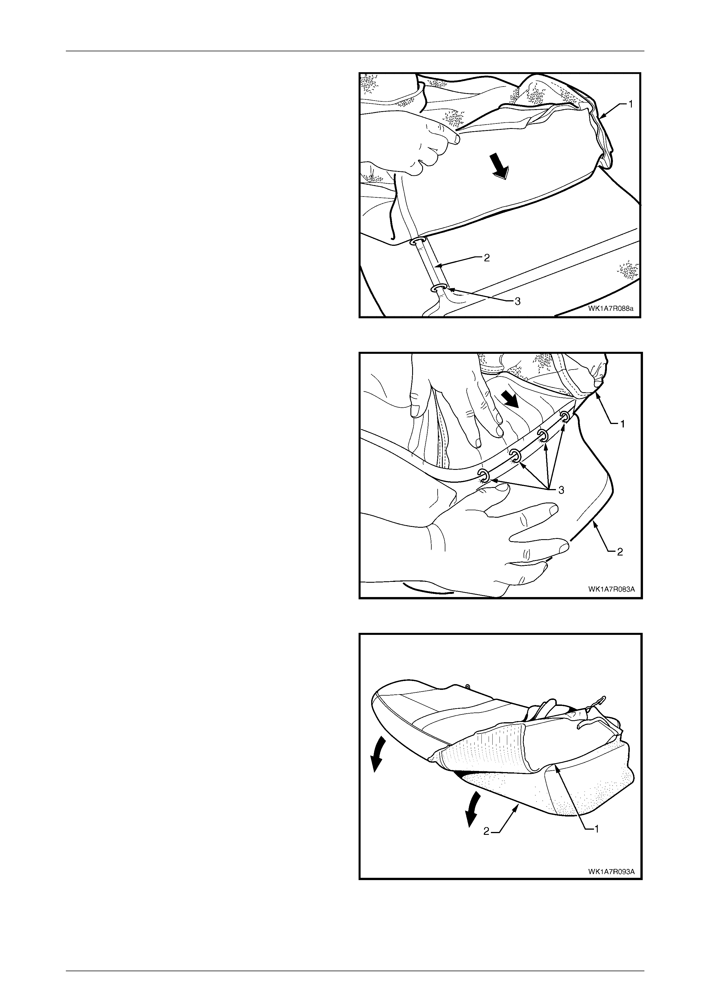
Seat Assemblies Page 1A7–338
Page 1A7–338
3 Continue to fold the cushion cover (1) into the front
and outer corresponding groove (2) of the seat and
working around to the corner, attach the cover with
hog rings (3), four places.
Figure 1A7 – 225
4 Working along the outer edge of the rear seat cushion,
position the cover (1) into the corresponding
groove (2) and attach with four hog rings (3).
5 Repeat the process for the opposite side of the rear
seat cushi on cov er.
Figure 1A7 – 226
6 Fold the rear seat cushion cover (1) over the corners
of the cushion pad (2) ensuring it is fitted neatly into all
corners and contours of the rear seat cushion.
NOTE
As part of their designed appearance, Leather
cushion covers have inherent minor creases in
the material.
Figure 1A7 – 227
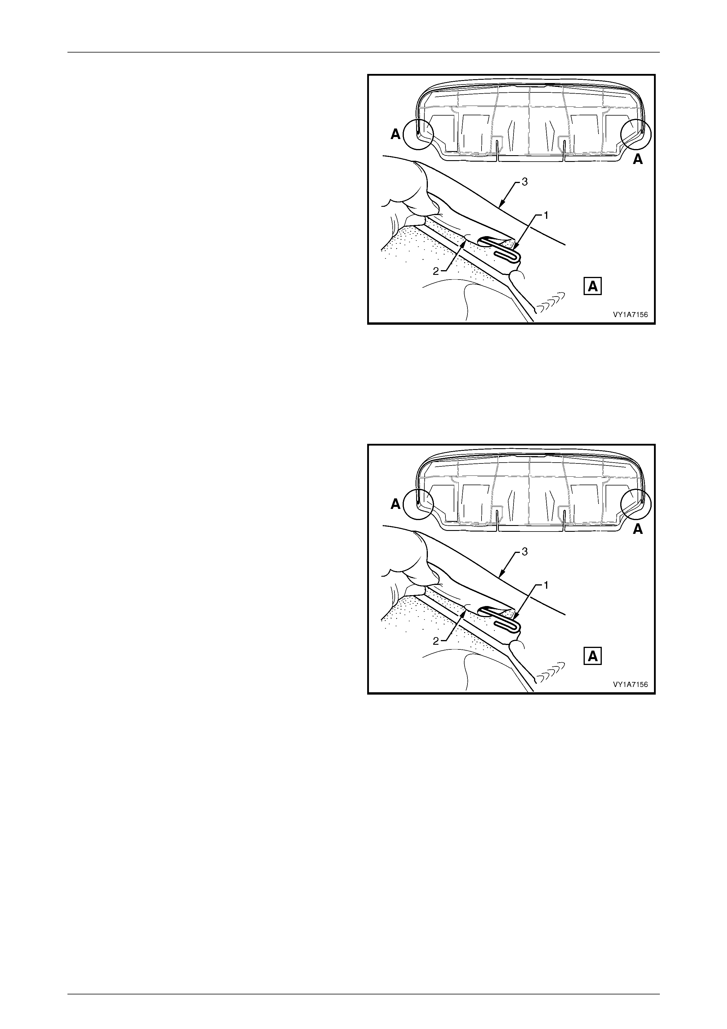
Seat Assemblies Page 1A7–339
Page 1A7–339
7 If removed, reinstall the retaining wire (1) from the
casing (2) attached to the cushion cover assembly (3).
8 Refit the rear seat cushion frame, refer to Rear Seat
Cushion Frame.
Figure 1A7 – 228
Rear Seat Type 4
Remove
1 If required, remove the rear seat cushion frame, refer to Rear Seat Cushion Frame.
2 If required, the retaining wire (1) from the casing (2)
attached to the rear seat cushion cover assembly (3).
Figure 1A7 – 229
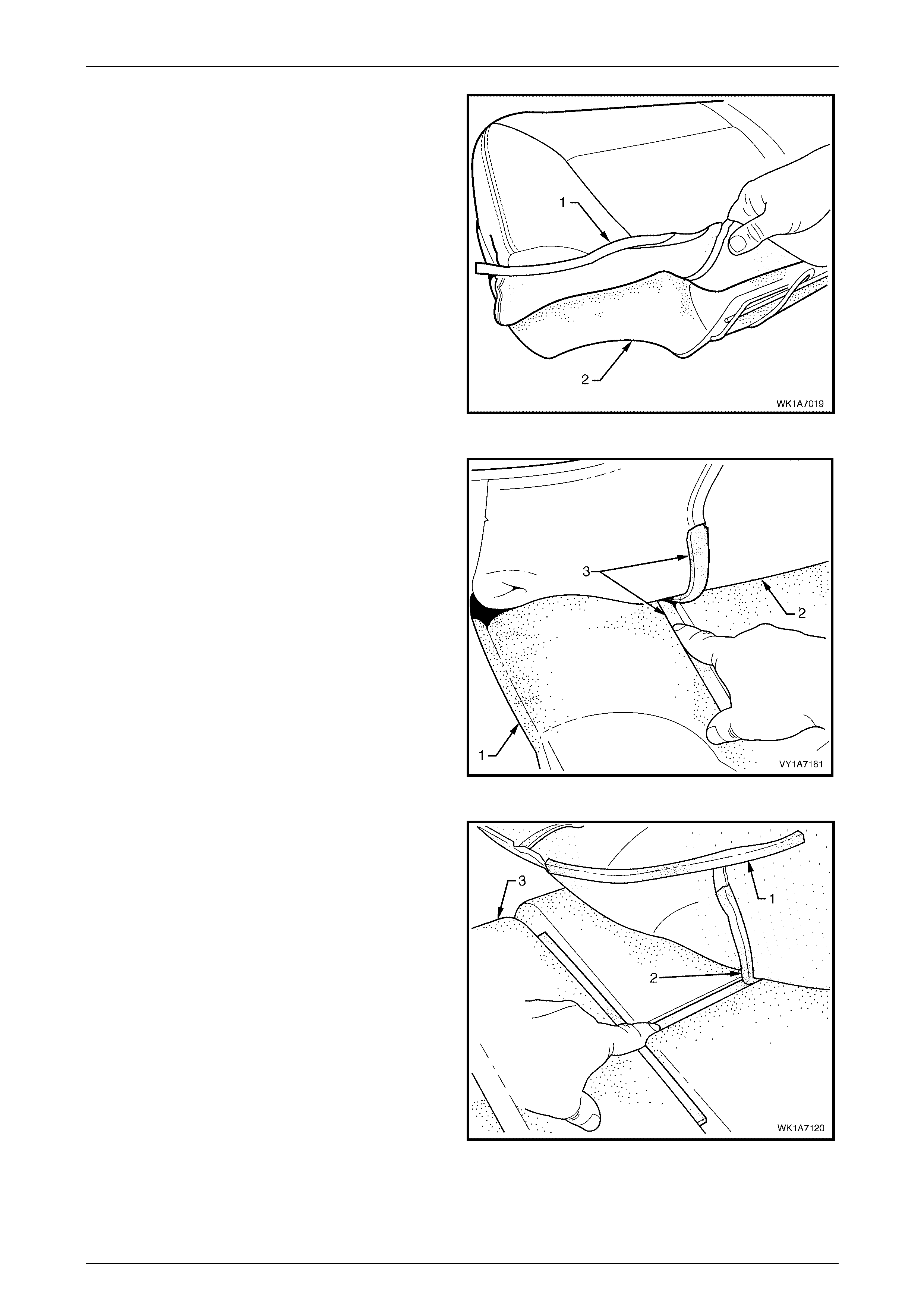
Seat Assemblies Page 1A7–340
Page 1A7–340
3 Fold the rear corner of the rear seat cushion cover (1)
over the rear seat cushion pad (2).
Figure 1A7 – 230
4 While holding the rear seat cushion pad (1), pull the
rear corner of the seat cushion cover (2) away from
the rear seat cushion pad to disengage the hook and
loop strip (3).
Figure 1A7 – 231
5 After disengaging the outer hook and loop stri p (1),
disengage the cross hook and loop strip (2) while
holding the seat cushion pad (3).
Figure 1A7 – 232

Seat Assemblies Page 1A7–341
Page 1A7–341
6 While holding the rear seat cushion pad (1),
disengage the inner hook and loop strip (2).
7 Repeat steps 3 to 6 for the opposite ha lf of the rear
seat cushio n asse mb ly .
8 Remove the rear seat cushion cover.
Figure 1A7 – 233
Reinstall
1 Align the inner hook and loop strip (1) and the cross
hook and loop strip (2), on the seat cushion cover (3)
with the seat cushion pad (4).
2 Press the folded edge of the rear seat cushion cover
firmly into the corresponding groove in the seat
cushion pad to engage the hook and loop strip.
Figure 1A7 – 234
3 Align and press the outer hook and loop strip (1), on
the seat cushion cover (2), with the corresponding
groove in the seat cushion pad (3).
4 Repeat this process for the opposite half of the rear
seat cover and pad, starting with the inner strip.
Figure 1A7 – 235
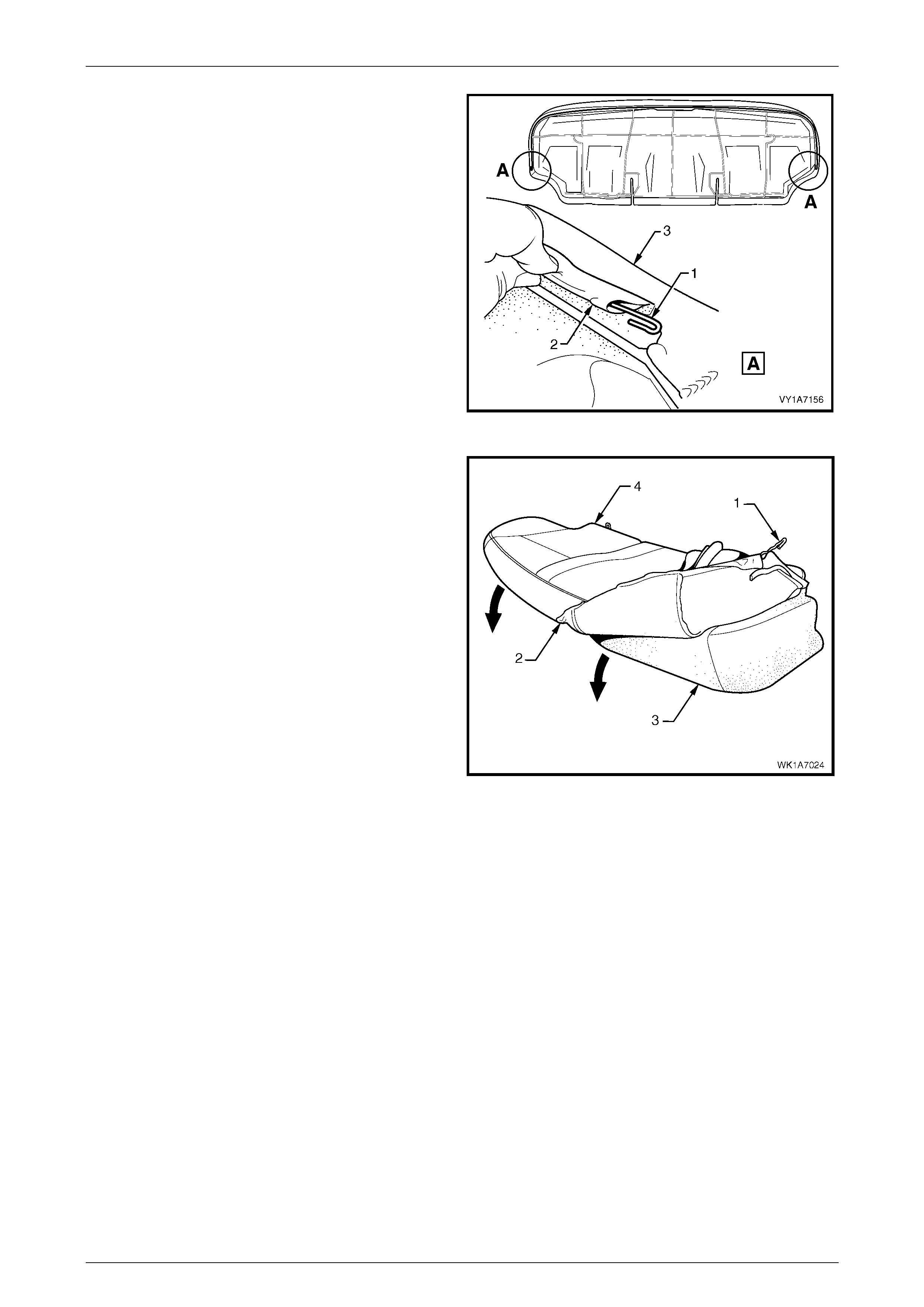
Seat Assemblies Page 1A7–342
Page 1A7–342
5 If removed, reinstall the retaining wire (1) from the
casing (2) attached to the cushion cover assembly (3).
Figure 1A7 – 236
6 With the retaining wire (1) fitted to the rear seat
cushion cover (2), roll the front corner of the cover
over the seat cushion pad (3).
7 Roll the sides of the seat cushion cover over the seat
cu shion pad.
8 Roll the rear corners (4) of the seat cushion cover over
the seat cushion pad.
NOTE
Ensure the pad is fitted neatly by hand into all
corners and contours of the seat cover.
9 Refit the rear seat cushion frame, refer to Rear Seat
Cushion Frame.
Figure 1A7 – 237
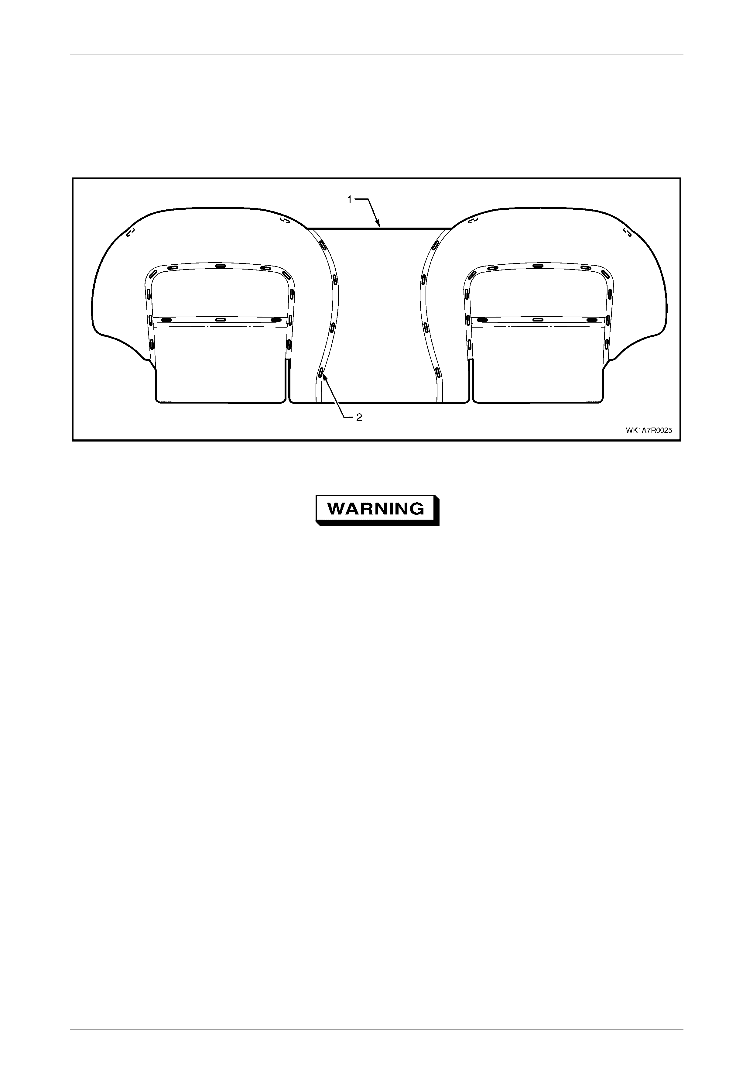
Seat Assemblies Page 1A7–343
Page 1A7–343
Rear Seat Type 7
Remove
The rear seat cushion cover (1) for rear seat Type 7 is attached to the cushion with approximately 40 hog rings in the
locations shown (2), refer to Figure 1A7 – 238.
Figure 1A7 – 238
Safety glasses and work gloves must be worn
at all times when removing the hog rings.
NOTE
Care must be taken when removing the hog rings
not to damage the cushion cover. All hog rings
will be destroyed during this operation and must
be replaced.
Using the following sequence of operations, cut the hog rings as they are revealed using bolt cutters or side cutters.
1 If required, remove the rear seat cushion frame, refer to Rear Seat Cushion Frame.
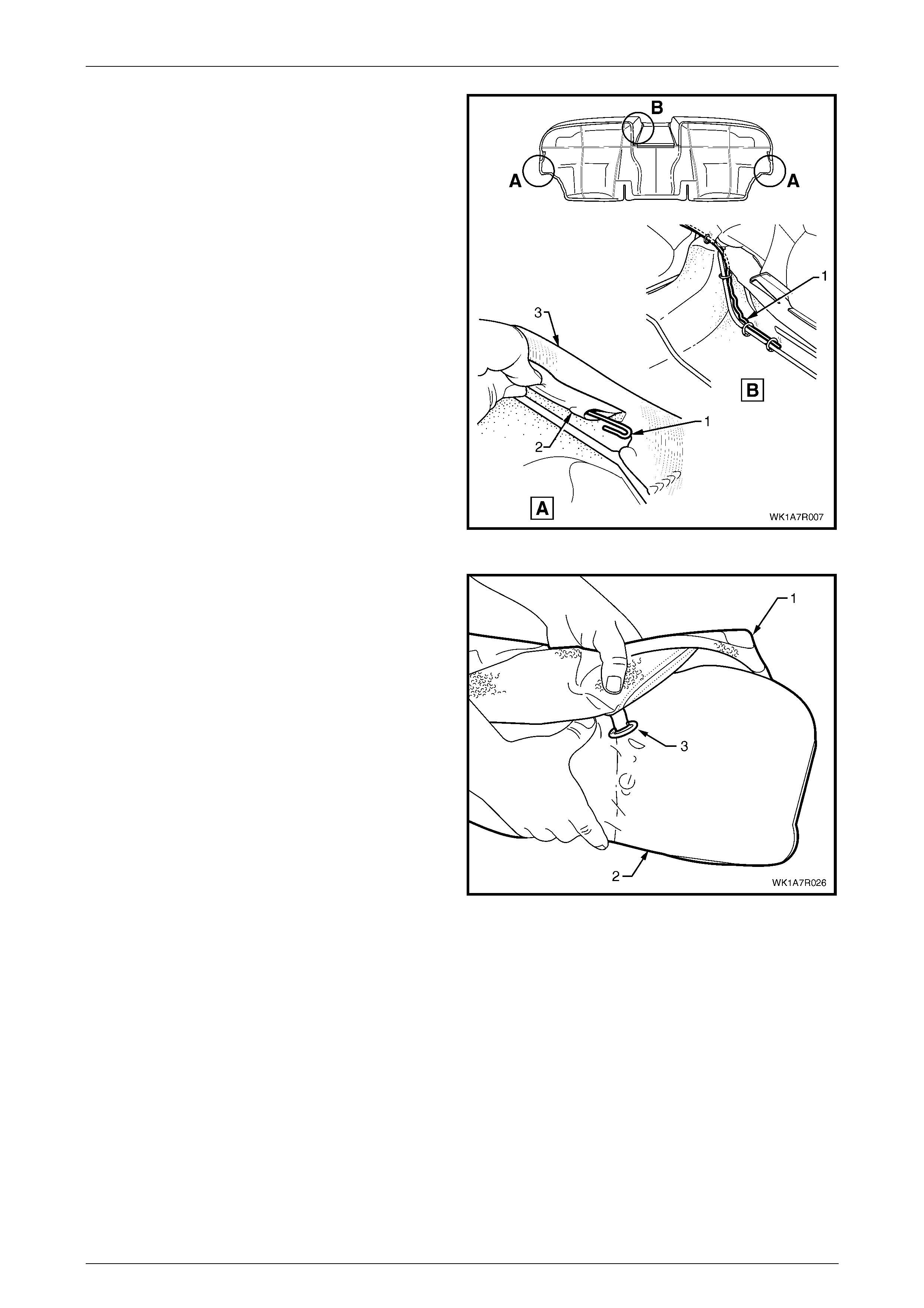
Seat Assemblies Page 1A7–344
Page 1A7–344
2 If required, remove the retaining wire (1) from the
casing (2) attached to the cushion cover assembly (3).
NOTE
The rear seat Type 7 retaining wire is in two
pieces with the break in the wire across the front
of the seat above the transmission tunnel.
Figure 1A7 – 239
3 Fold the rear corner of the rear seat cushion cover (1)
over the seat cushion pad (2), then fold the front
corner of the cover up revealing the hog ring (3).
Figure 1A7 – 240
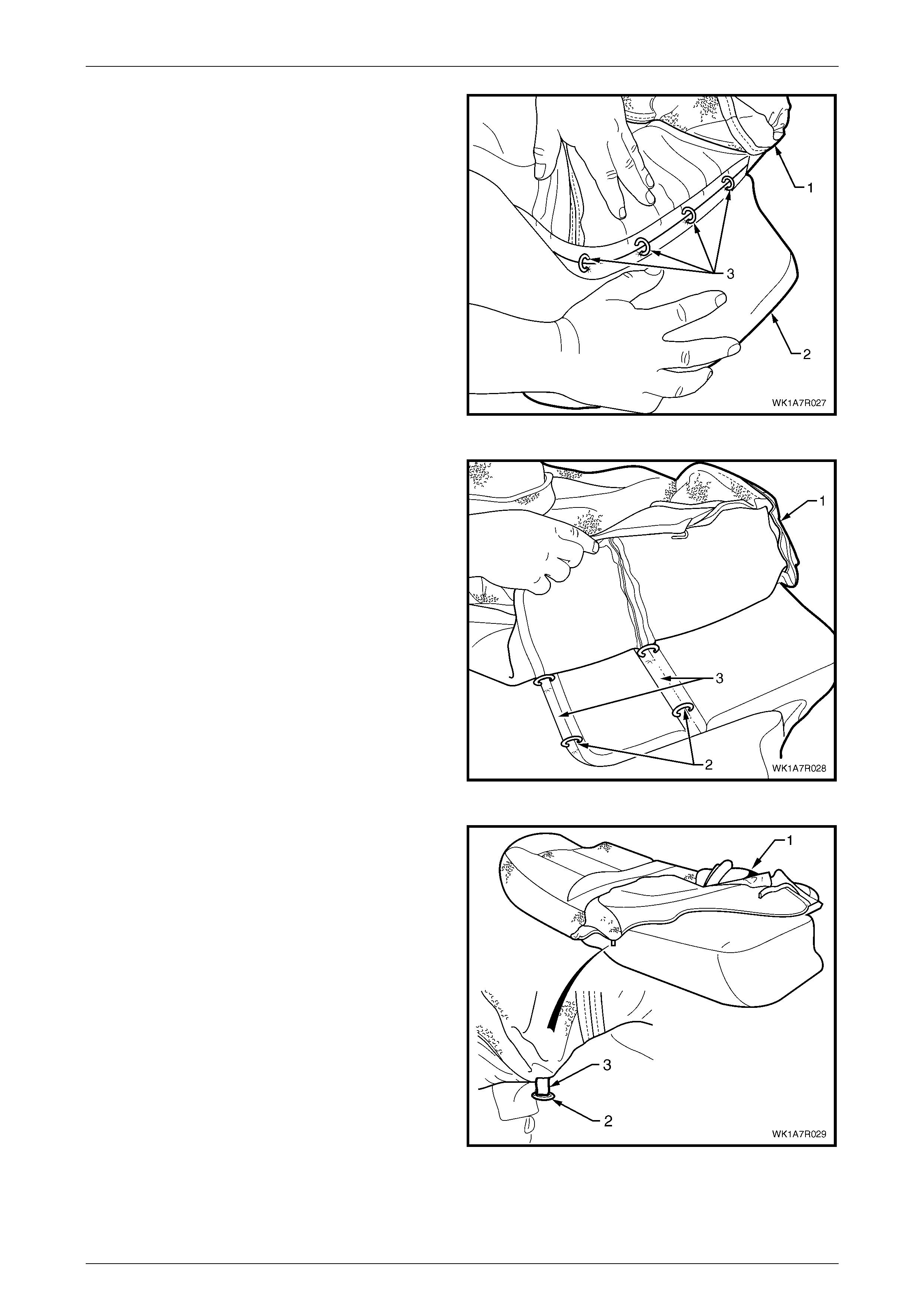
Seat Assemblies Page 1A7–345
Page 1A7–345
4 Fold the cushion cover (1) back while holding the
cushion pad (2) revealing the four hog rings (3) and
cut to remove.
Figure 1A7 – 241
5 Working towards the centre of the seat cushion,
carefully fold back the cover (1) revealing two outer
hog rings (2), cut these and continue folding the cover
back until all three hog rings in each corresponding
groove (3) have been removed.
Figure 1A7 – 242
6 Fold the front of the cushion cover (1) back revealing
the hog ring (2) taking care not to damage the cushion
cover tag (3) or the cover and remove the hog ring.
Figure 1A7 – 243
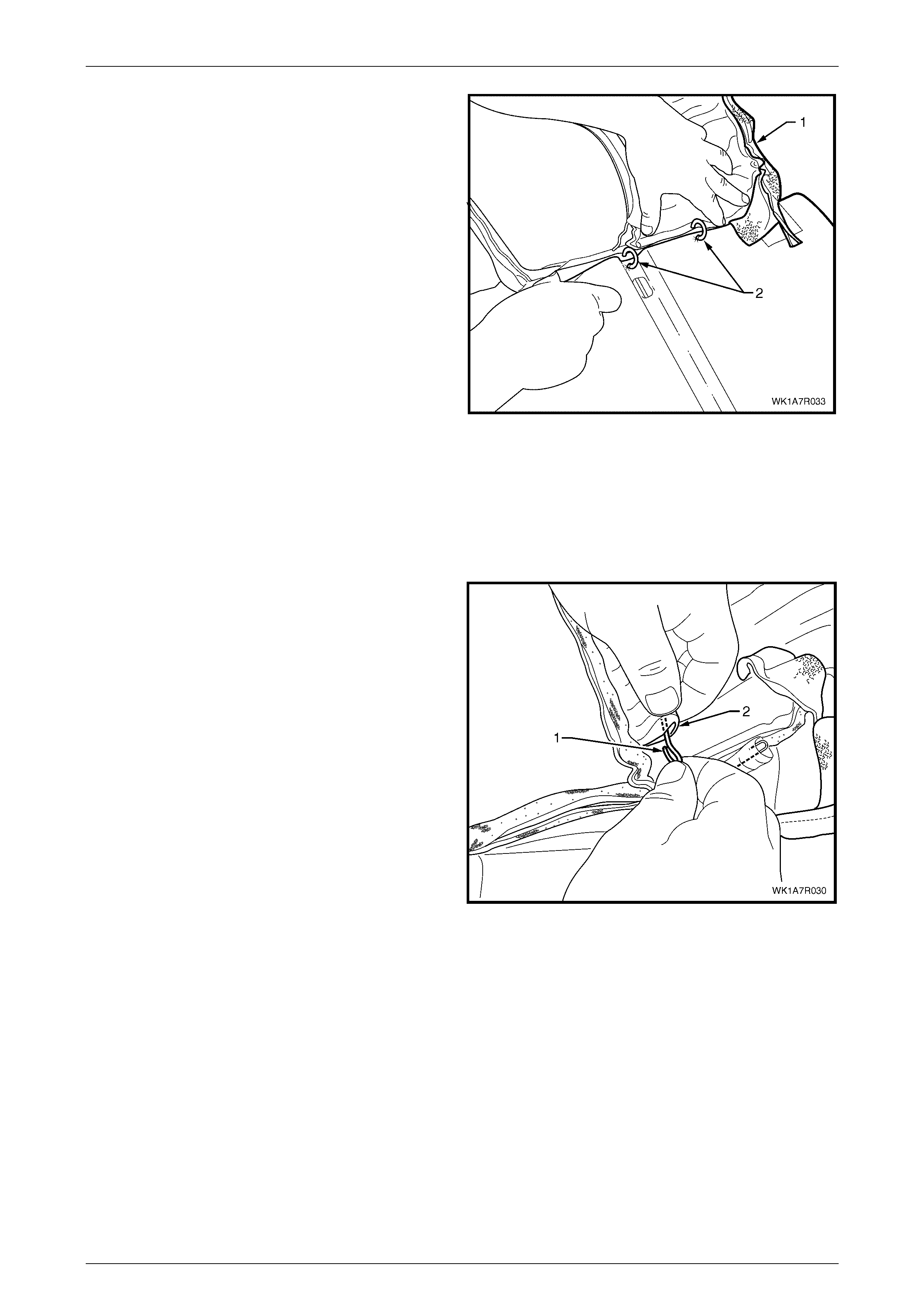
Seat Assemblies Page 1A7–346
Page 1A7–346
7 Continue to fold the cushion over towards the centre
and from the rear of the seat cushion, cut the hog
rings (2), in four places, while working towards the
front.
8 Continue to fold the cushion cover back towards the
centre and repeat the process for the centre groove.
9 Repeat the process for the other side of the rear seat
cushion.
10 Remove the cushion cover from the cushion.
Figure 1A7 – 244
NOTE
The cushion cover has six retaining wires that
align to the grooves in the cushion pad and are
used to hook the hog rings to. These will need to
be removed from the cover if it is to be replaced.
11 If required, remo ve the retaining wire (1) from the
casing (2) and repeat for the remaining five places.
Figure 1A7 – 245
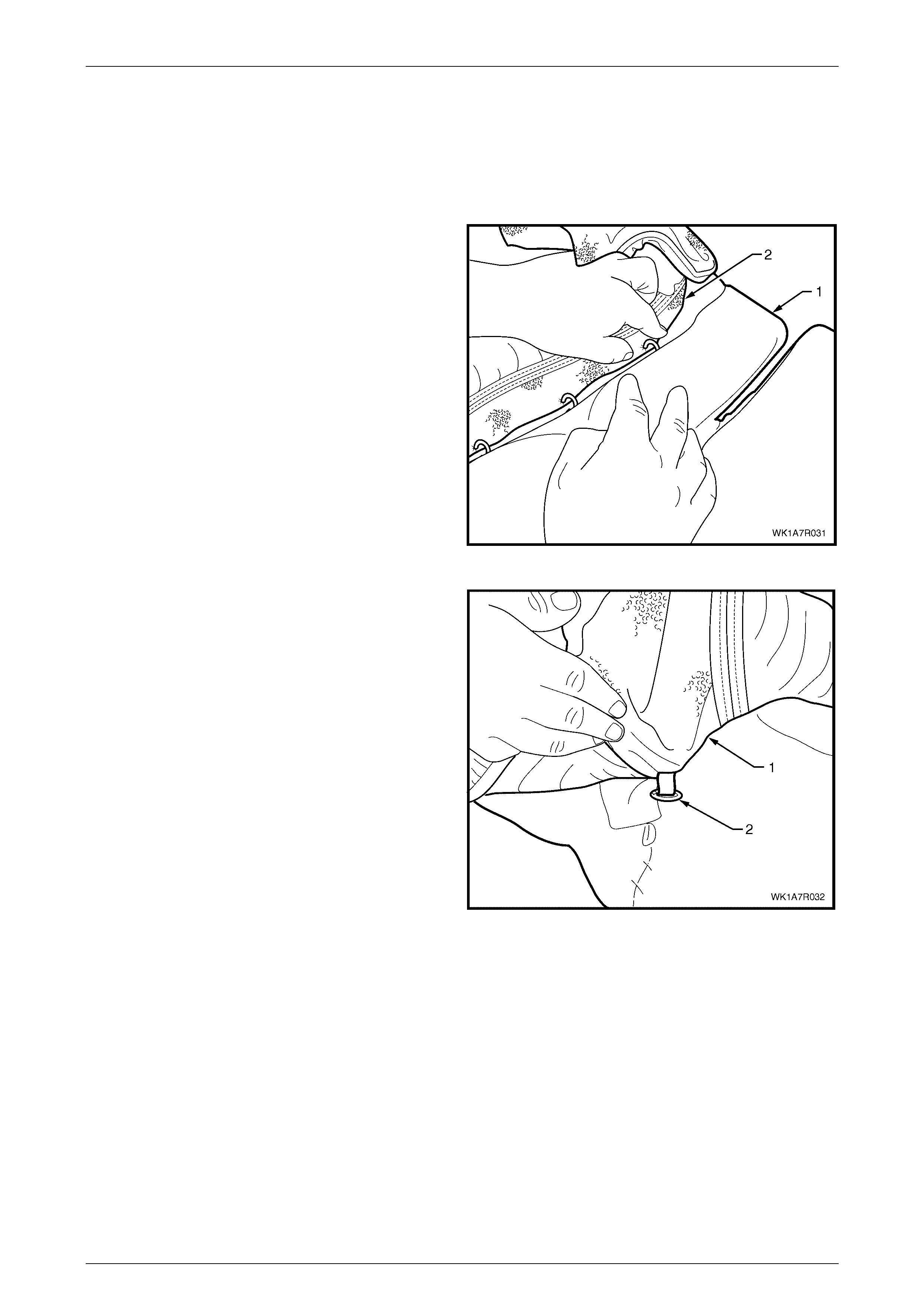
Seat Assemblies Page 1A7–347
Page 1A7–347
Reinstall
Referring to Figure 1A7 – 238 showing the hog ring locations, install the rear seat cushion cover using the following
sequence of operations, attaching the hog rings with hog ring pliers.
1 If required, reinstall the retaining wire (1) into the casing (2) in six locations in the cushion cover assembly, refer to
Figure 1A7 – 245.
2 Beginning on one side of the rear seat cushion (1)
position the cover (2) into the centre corresponding
groove. Starting at the rear and working towards the
front, attach with four hog rings using hog ring pliers.
NOTE
Ensure the cushion cover aligns to all the
grooves in the cushion pad before attaching the
cover with hog rings.
Figure 1A7 – 246
3 Working outward, start from the front of the cushion,
fold the cushion cover (1) over the front and attach the
hog ring (2).
Figure 1A7 – 247
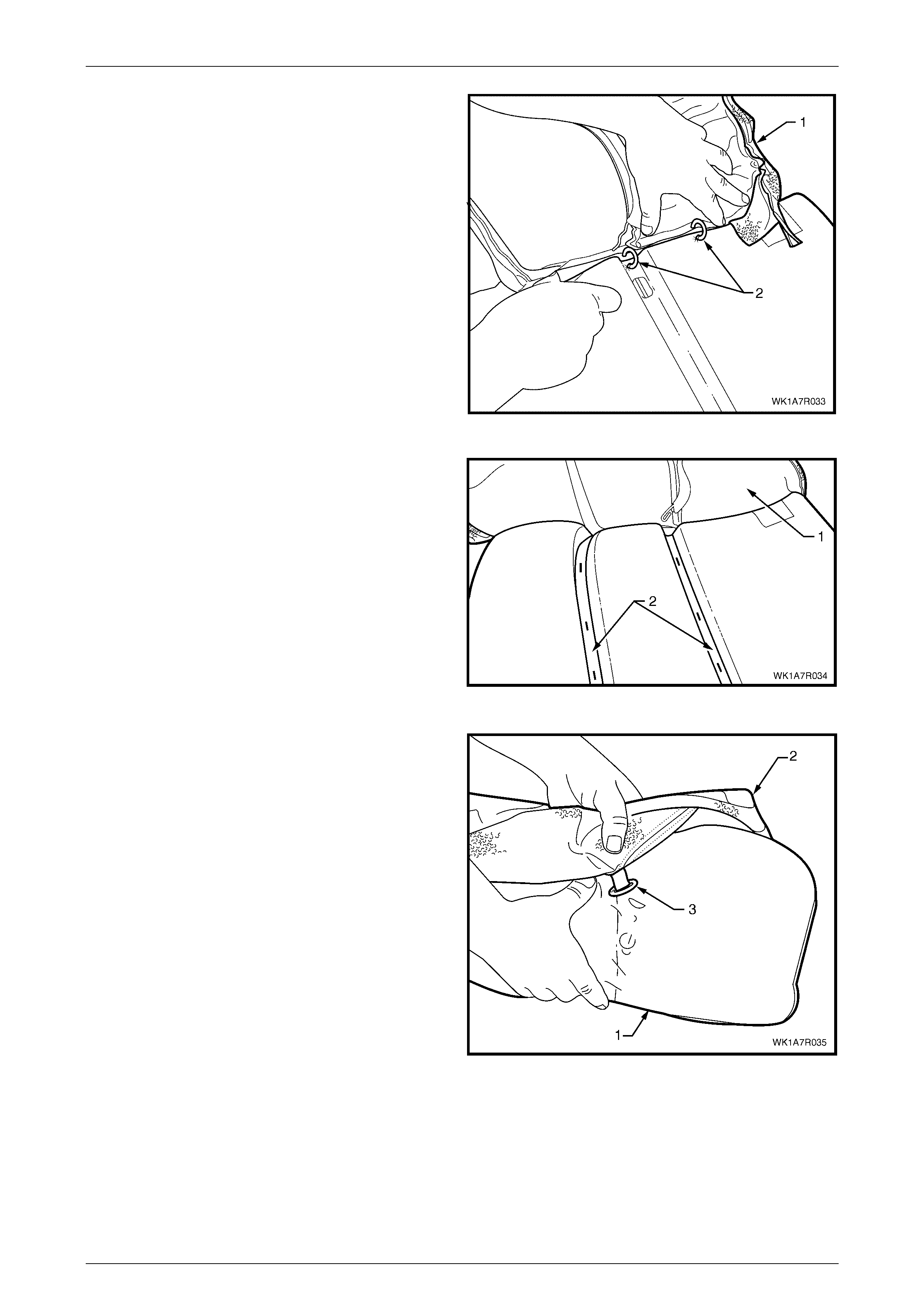
Seat Assemblies Page 1A7–348
Page 1A7–348
4 Fold the cushion cover (1) into the corresponding
groove and from the front of the seat and working
around to the rear, attach the cover with four hog
rings (2).
Figure 1A7 – 248
5 From the centre of the cushion, position the cover (1)
into the corresponding grooves (2) and attach with six
hog rings.
Figure 1A7 – 249
6 At the front of the rear seat cushion pad (1), fold the
cushion cover (2) over the top and attach the hog ring
(3).
Figure 1A7 – 250
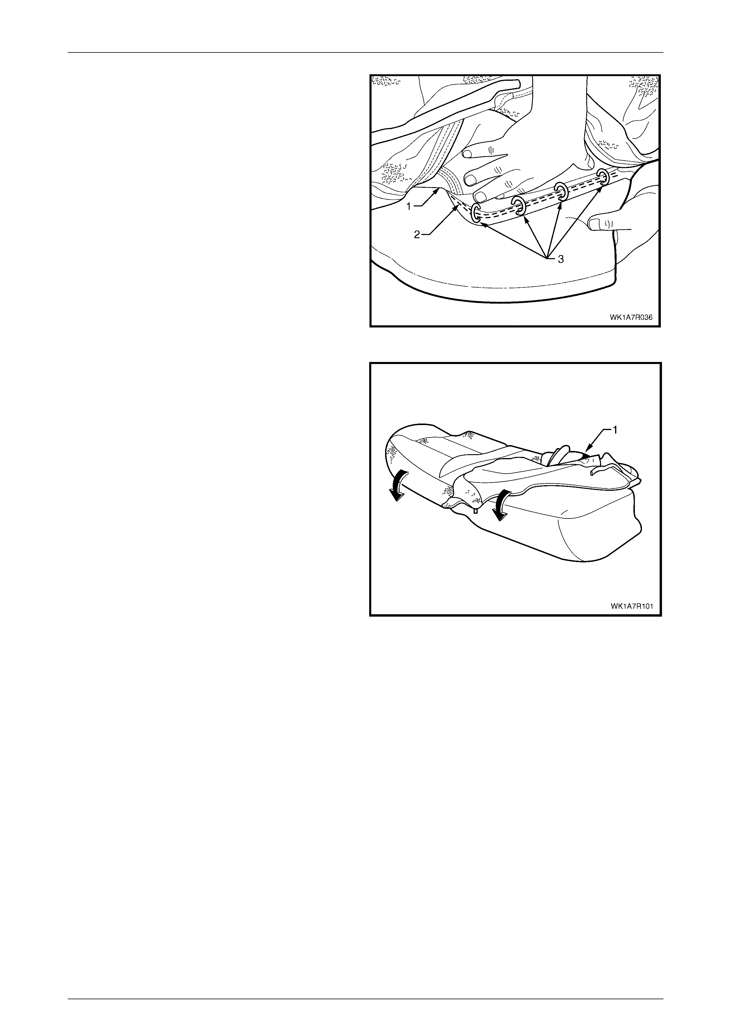
Seat Assemblies Page 1A7–349
Page 1A7–349
7 Working along the side of the rear seat cushion,
position the cover (1) into the corresponding
groove (2) and attach with four hog rings (3).
8 Repeat the process for the opposite side of the rear
seat cushi on cov er.
NOTE
As part of their designed appearance, Leather
cushion covers have inherent minor creases in
the material.
Figure 1A7 – 251
9 Fold the rear seat cushion cover (1) over the corners
of the cushion ensuring the cushion cover is fitted
neatly into all corners and con tours of the rear seat
cushion.
Figure 1A7 – 252
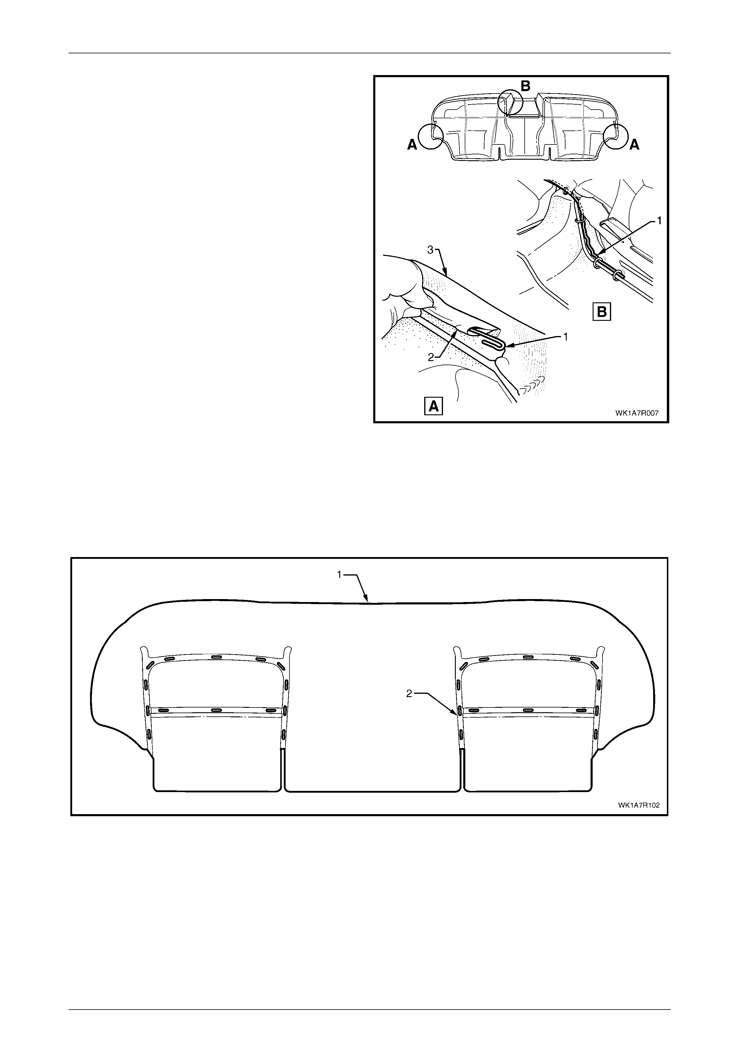
Seat Assemblies Page 1A7–350
Page 1A7–350
10 If removed, reinstall the retaining wire (1) from the
casing (2) attached to the cushion cover assembly (3).
NOTE
The rear seat Type 7 retaining wire is in two
pieces with the break in the wire across the front
of the seat above the transmission tunnel.
11 Refit the rear seat cushion frame, refer to
Rear Seat Cushion Frame.
Figure 1A7 – 253
Rear Seat Type 8
Remove
The rear seat cushion cover (1) for rear seat Type 8 is attached to the cushion with approximately 28 hog rings (2) in the
locations shown, refer to Figure 1A7 – 254.
Figure 1A7 – 254
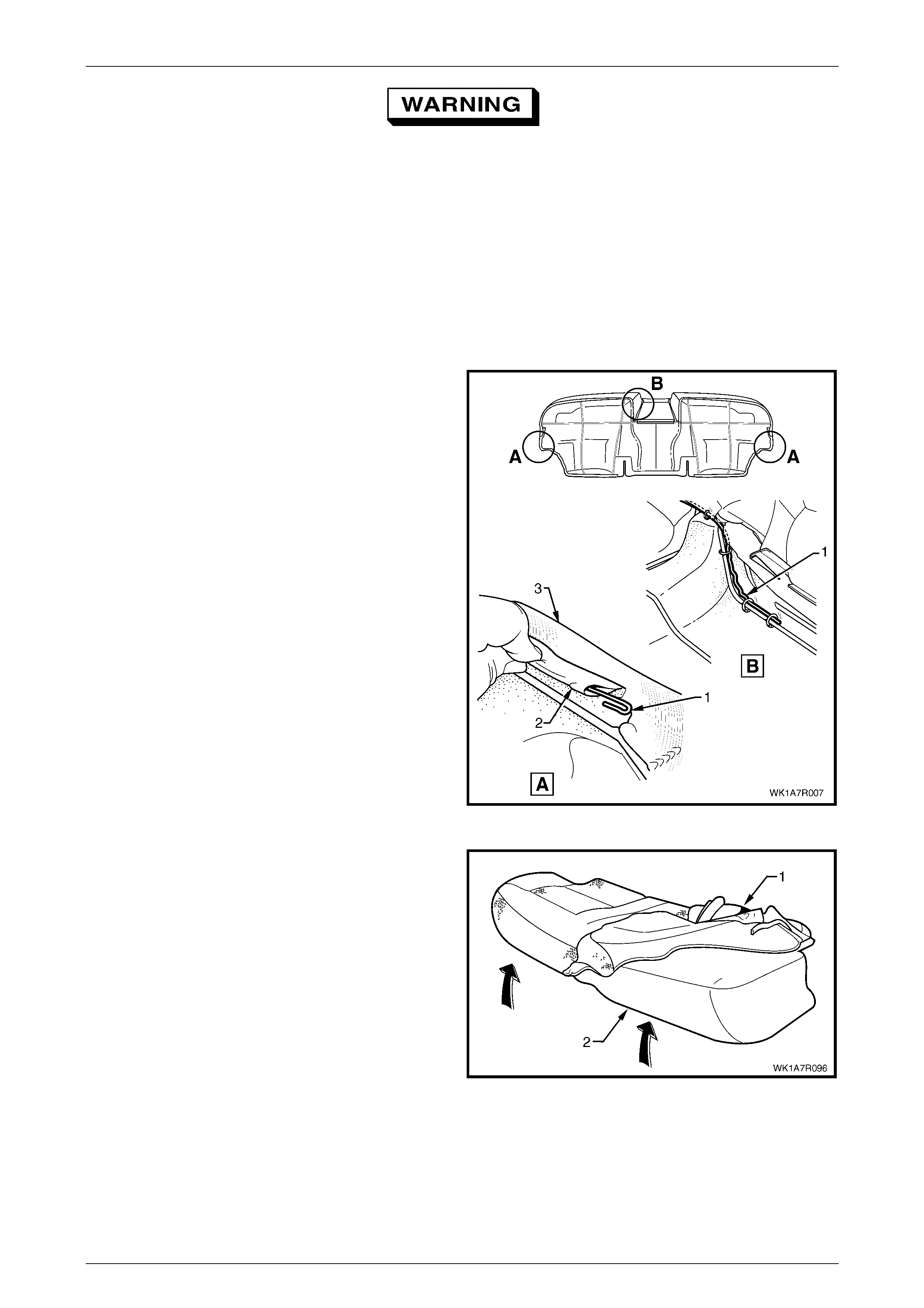
Seat Assemblies Page 1A7–351
Page 1A7–351
Safety glasses and work gloves must be worn
at all times when removing the hog rings.
NOTE
Care must be taken when removing the hog rings
not to damage the cushion cover. All hog rings
will be destroyed during this operation and must
be replaced.
Using the following sequence of operations, cut all hog rings as they are revealed using bolt cutters or side cutters.
1 If required, remove the rear seat cushion frame, refer to Rear Seat Cushion Frame.
2 If required, remove the retaining wire (1) from the
casing (2) attached to the cushion cover assembly (3).
NOTE
The rear seat Type 8 retaining wire is in two
pieces with the break in the wire across the front
of the seat above the transmission tunnel cut-
out.
Figure 1A7 – 255
3 Fold the rear corner of the rear seat cushion cover (1),
up over the rear seat cushion pad (2) then, fold the
front corner of the cover up.
Figure 1A7 – 256
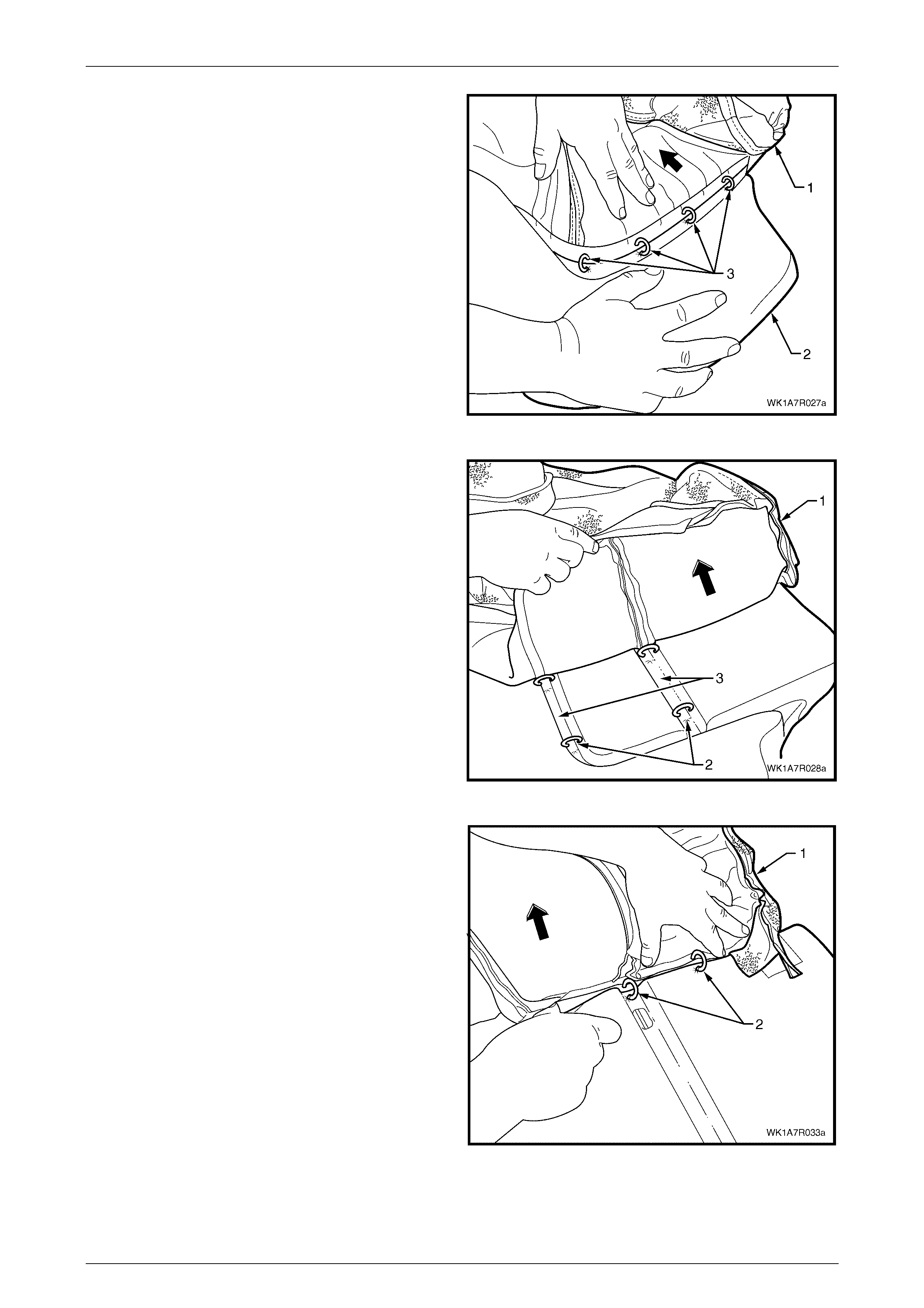
Seat Assemblies Page 1A7–352
Page 1A7–352
4 Fold the cushion cover (1) back towards the centre of
the seat cushion while holding the cushion pad (2) to
reveal the four hog rings (3) and cut to remove.
Figure 1A7 – 257
5 Continue working towards the centre of the seat
cushion, ca refully fold back the cover (1) revealing two
outer hog rings (2), cut these and continue folding the
cover back until all three hog rings in each
corresponding groove (3) have been re moved.
Figure 1A7 – 258
6 Fold the cushion (1) over towards the centre and from
the front of the seat cushion, cut the hog rings (2), in
four places.
7 Repeat steps 3 to 6 for the other side of the rear seat
cushion and remove t he cus hion cover f rom the
cushion.
Figure 1A7 – 259
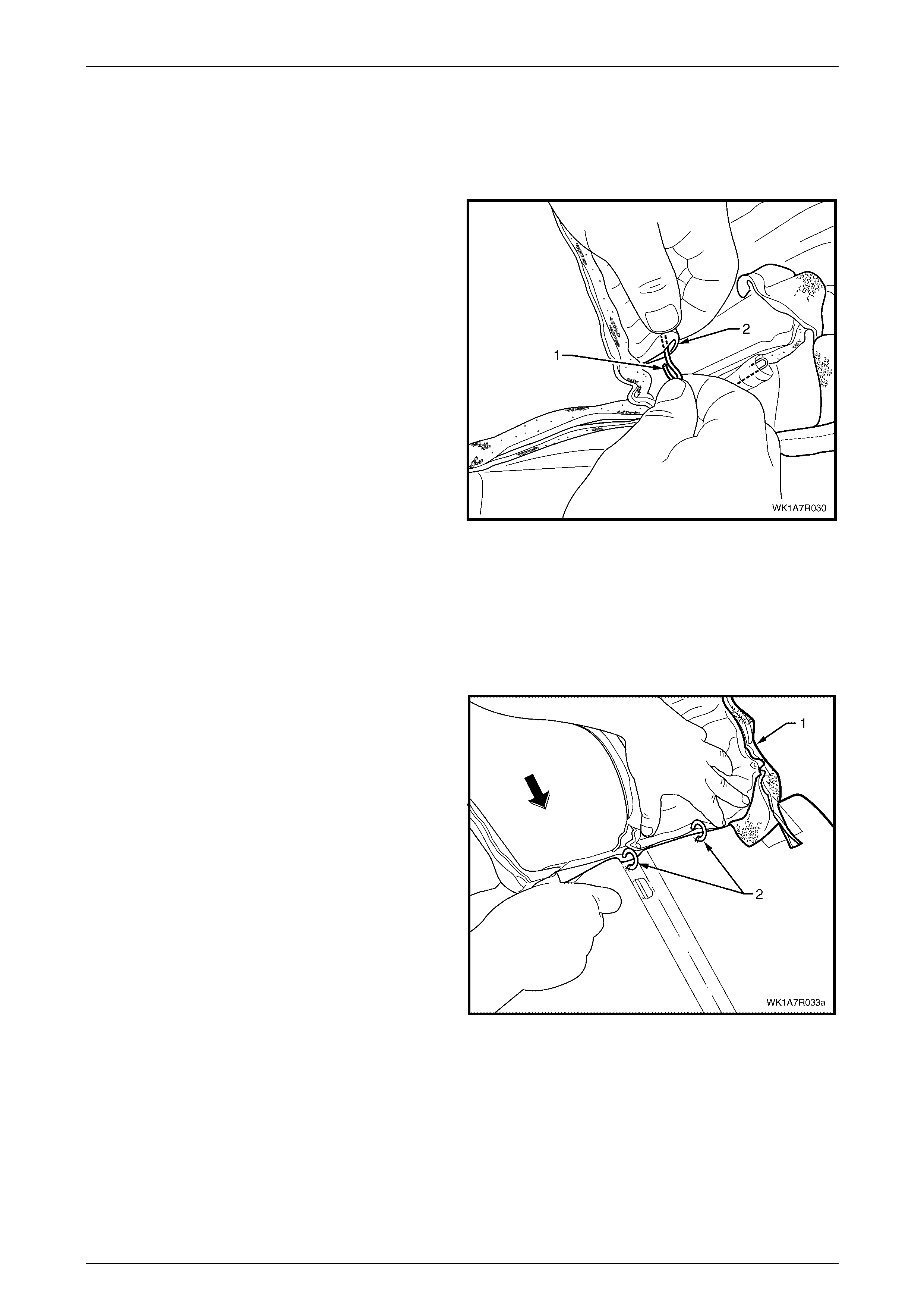
Seat Assemblies Page 1A7–353
Page 1A7–353
NOTE
The cushion cover has eight retaining wires that
align to the grooves in the cushion pad and are
used to hook the hog rings to. These will need to
be removed from the cover if it is to be replaced.
8 If required, remove the retaining wire (1) from the
casing (2) and repeat for the re maining seven places.
Figure 1A7 – 260
Reinstall
Referring to Figure 1A7 – 254 showing the hog ring locations, install the rear seat cushion cover using the following
sequence of operations, attaching the hog rings with hog ring pliers.
If required, reinstall the retaining wire (1) into the casing (2) in eight locations in the cushion cover assembly, refer to
Figure 1A7 – 260.
1 Beginning on one side of the cushion, pos itio n the
cover (1) into the inner corresponding groove. Starting
at the rear and working towards the front, attach the
cushion cover to the cushion pad with hog rings (2)
four places using, hog ring pli e rs.
NOTE
Ensure the cushion cover aligns to all the
grooves in the cushion pad before attaching the
cover with hog rings.
Figure 1A7 – 261
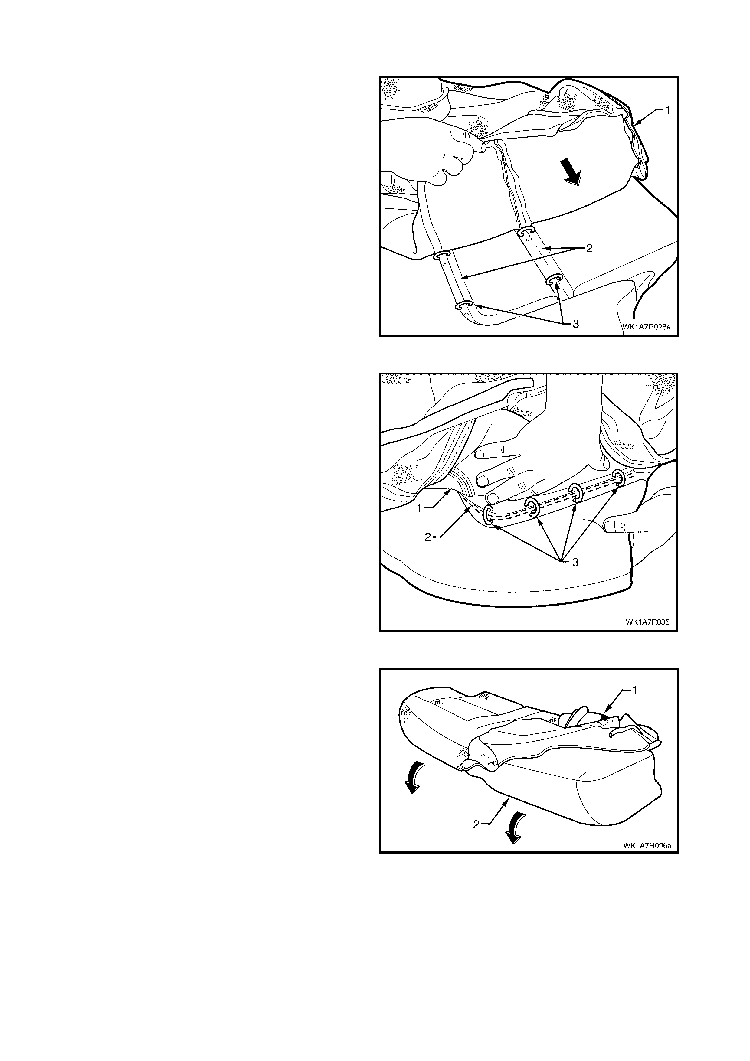
Seat Assemblies Page 1A7–354
Page 1A7–354
2 Working outward, position the cushion cover (1), into
the corresponding grooves (2) and attach with hog
rings (3).
Figure 1A7 – 262
3 Working along the outside edge of the rear seat
cushion, position the cover (1) into the outer
corresponding groove (2) and attach with four hog
rings (3).
4 Repeat the process for the opposite side of the rear
seat cushi on cov er.
Figure 1A7 – 263
5 Fold the rear seat cushion cover (1) over the corners
of the cushion pad (2), ensuring that the cushion cover
is fitted neatly into all corners and contours of the rear
seat cushion.
NOTE
As part of their designed appearance, Leather
cushion covers have inherent minor creases in
the material.
Figure 1A7 – 264
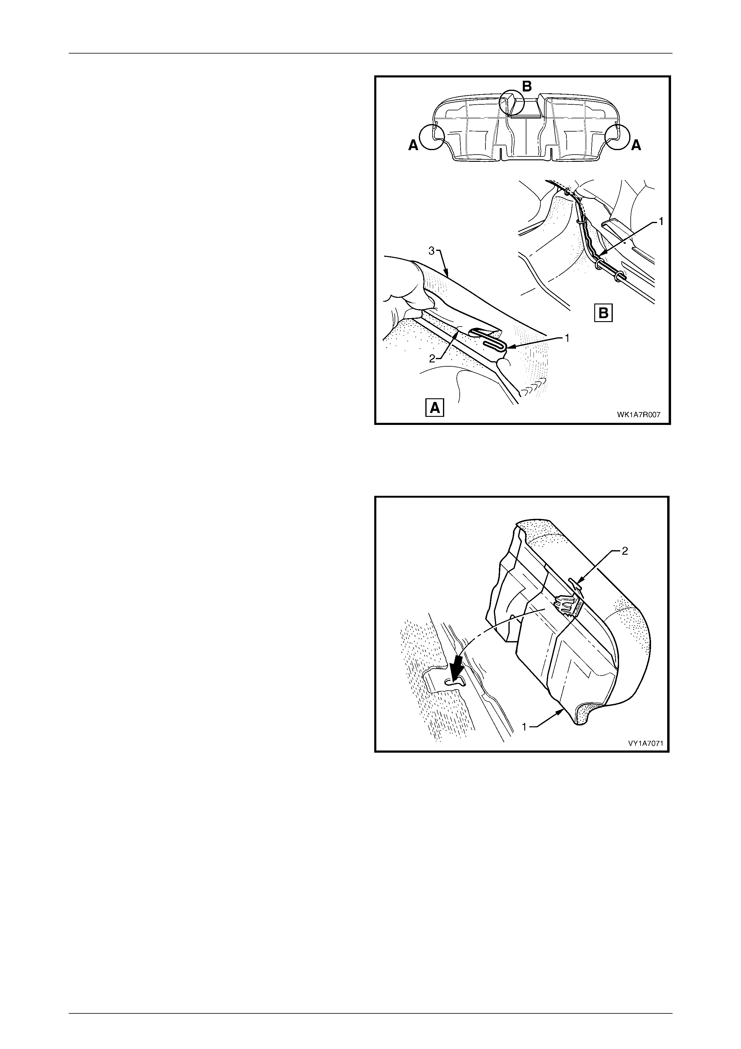
Seat Assemblies Page 1A7–355
Page 1A7–355
6 If removed, reinstall the retaining wire (1) from the
casing (2) attached to the cushion cover assembly (3).
NOTE
The rear seat Type 8 retaining wire is in two
pieces with the break in the wire across the front
of the seat above the transmission tunnel.
7 Refit the rear seat cushion frame, refer to Rear Seat
Cushion Frame.
Figure 1A7 – 265
Reinstall
1 Sit the rear seat cushion assembly into position.
2 Push the rear seat cushion assembly (1) into the seat-
back and push the front of the cushion assembly down
until the locking mec hanisms (2) lock into position.
Figure 1A7 – 266
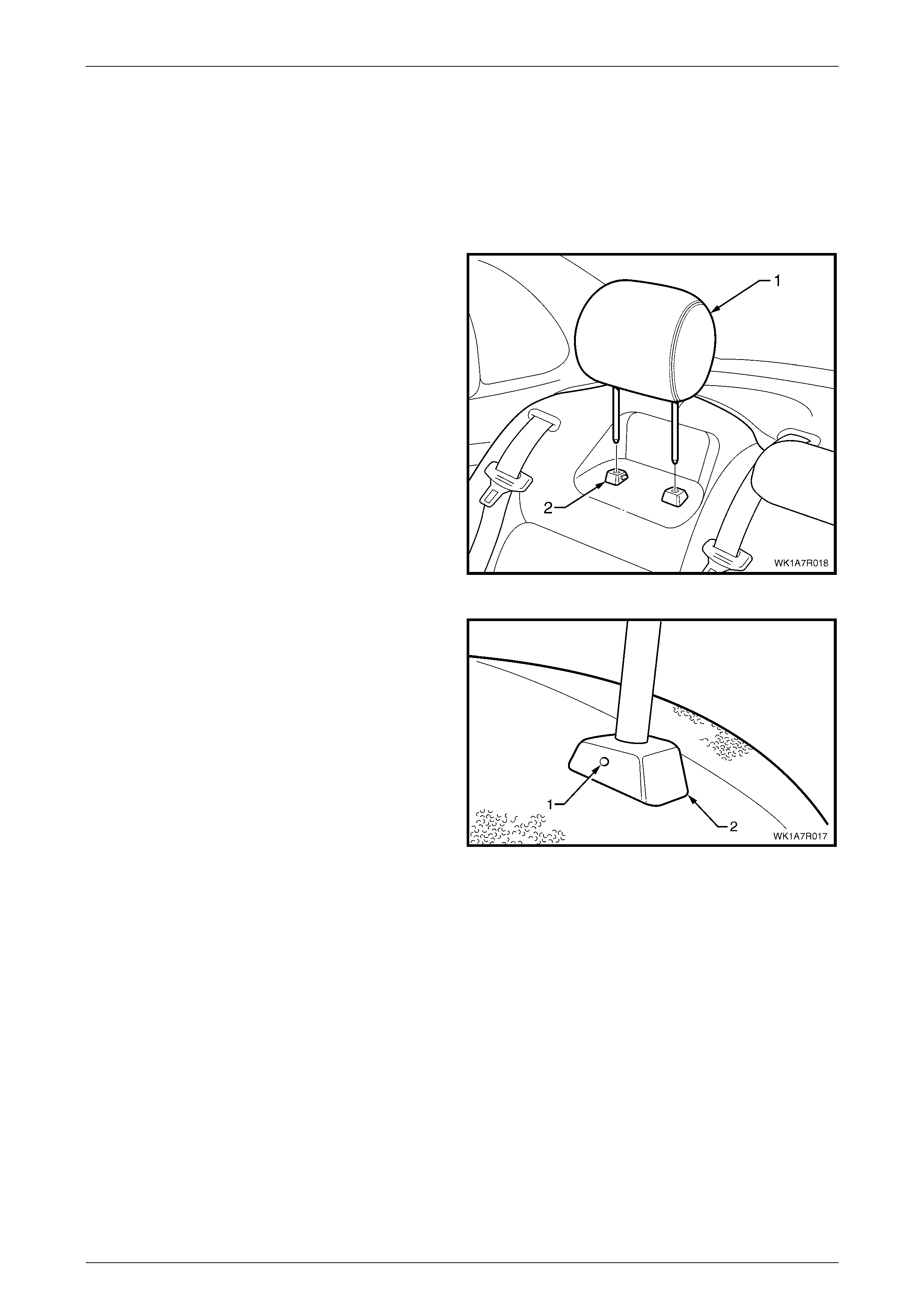
Seat Assemblies Page 1A7–356
Page 1A7–356
7.3 Rear Seat-back Head Restraint Assembly
Right and Left-hand Side
LT Section No. – 14-350
Remove
1 Raise the rear seat-back head restraint assembly (1)
to the first stop position.
2 Depress the head restraint sleeve height adjuster
lock (2) and raise the head restraint to the upper stop
position.
Figure 1A7 – 267
3 Manufacture a suitable size probe and insert into the
hole (1) in the inboard head restraint sleeve (2).
4 Push the probe in slightly while applying slight upward
pressure on the headrest and remove the head
restraint completely out of the sleeve.
Figure 1A7 – 268
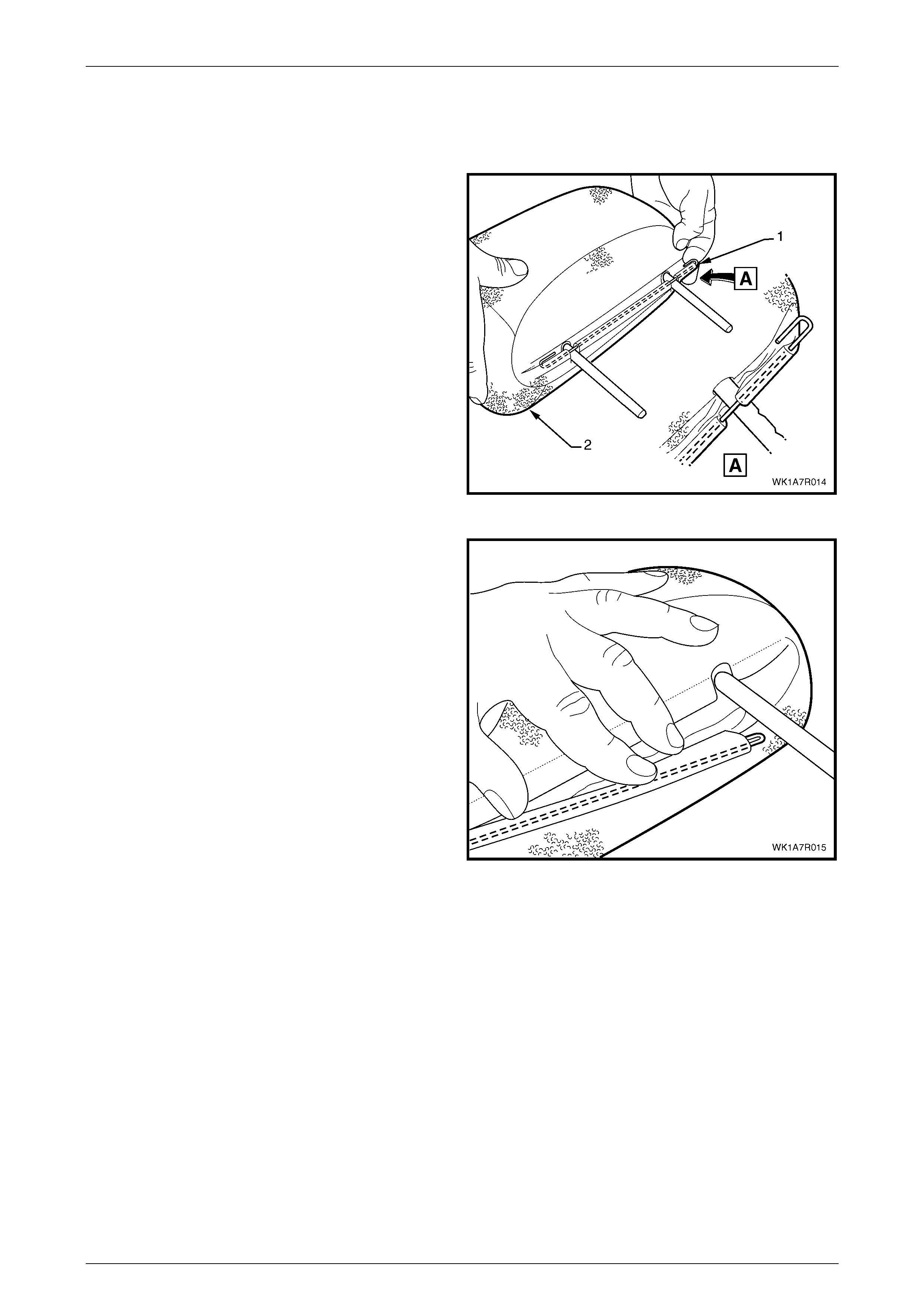
Seat Assemblies Page 1A7–357
Page 1A7–357
Except Rear Seat Type 4 Head Restraint
Disassemble
1 Unhook the wire retainer (1) from the head restraint
cover (2).
Figure 1A7 – 269
2 Carefully pull the wire retainer through the head
restraint cover and remove.
3 Repeat the process for the remaining wire retainer.
Figure 1A7 – 270
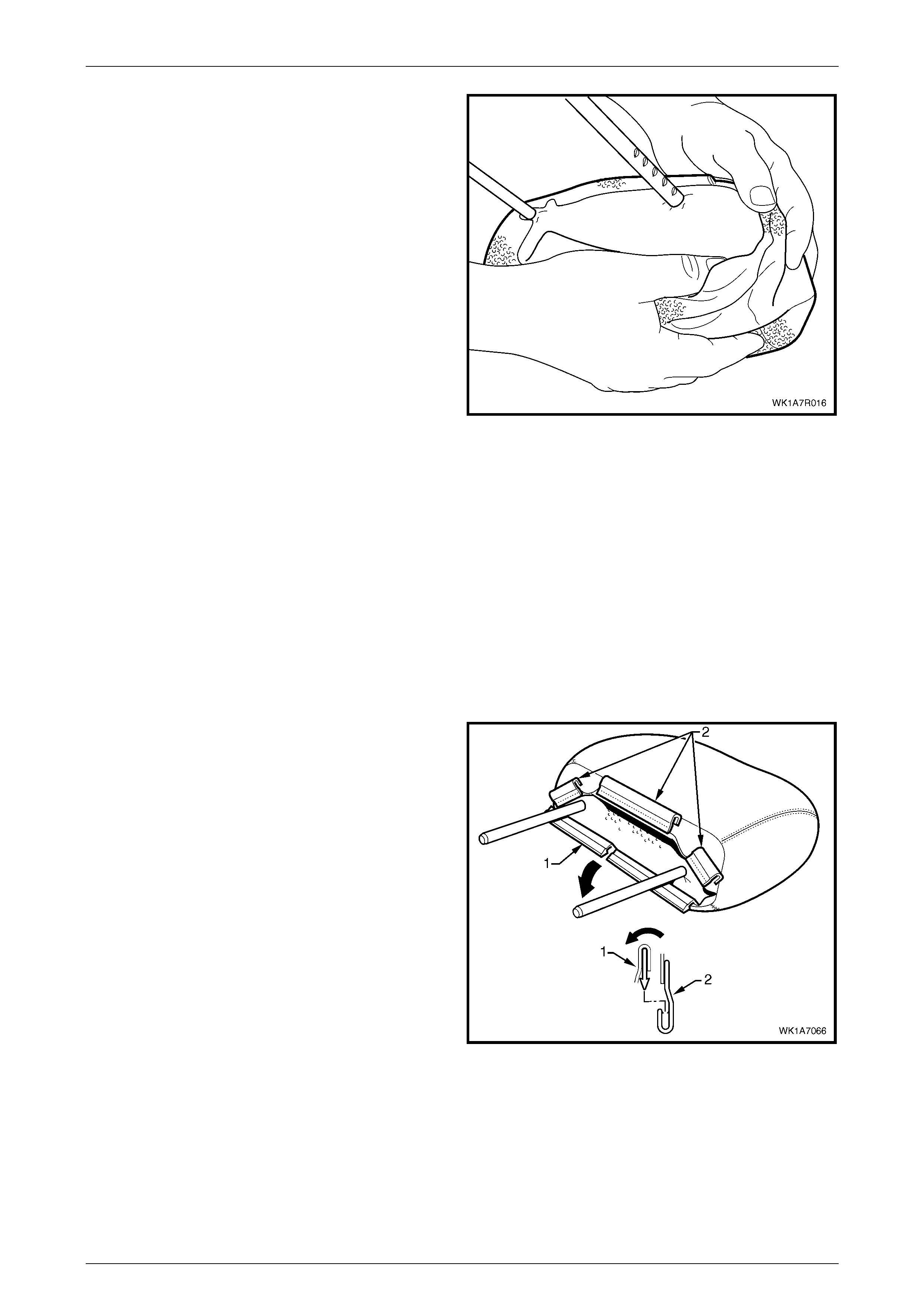
Seat Assemblies Page 1A7–358
Page 1A7–358
4 Starting at one end, gently pull the head restraint
cover back over the head restraint pad and remove.
Figure 1A7 – 271
Reassemble
Reassembly of the rear seat-back head restraint assembly is the reverse of the removal procedure, noting the following:
1 Align the cover to the head restraint pad taking note of the contour of both the cover and the pad.
2 Position the head restraint pad inner liner so that it covers the pad.
3 Both loops on the wire retainer are hooked into the rear seat-back head restraint cover.
4 Ensure the cover is fitted neatly to the head restraint pad and has no creases.
Rear Seat Type 4 Head Restraint
Disassemble
1 Disengage the front head restraint cove r J-strip by
pulling the flap (1) back and out of flap (2) in the
direction shown.
2 Beginning at one corner of the head restraint, gently
remove the co ver from the pad assembly.
Figure 1A7 – 272
Reassemble
Reassembly of the rear seat-back head restraint assembly is the reverse of the removal procedure. Ensure the head
restraint cover J-strip is fully engaged and the cover is fitted neatly with no creases.
Reinstall
1 Position the head restraint in the sleeves and push down firmly.
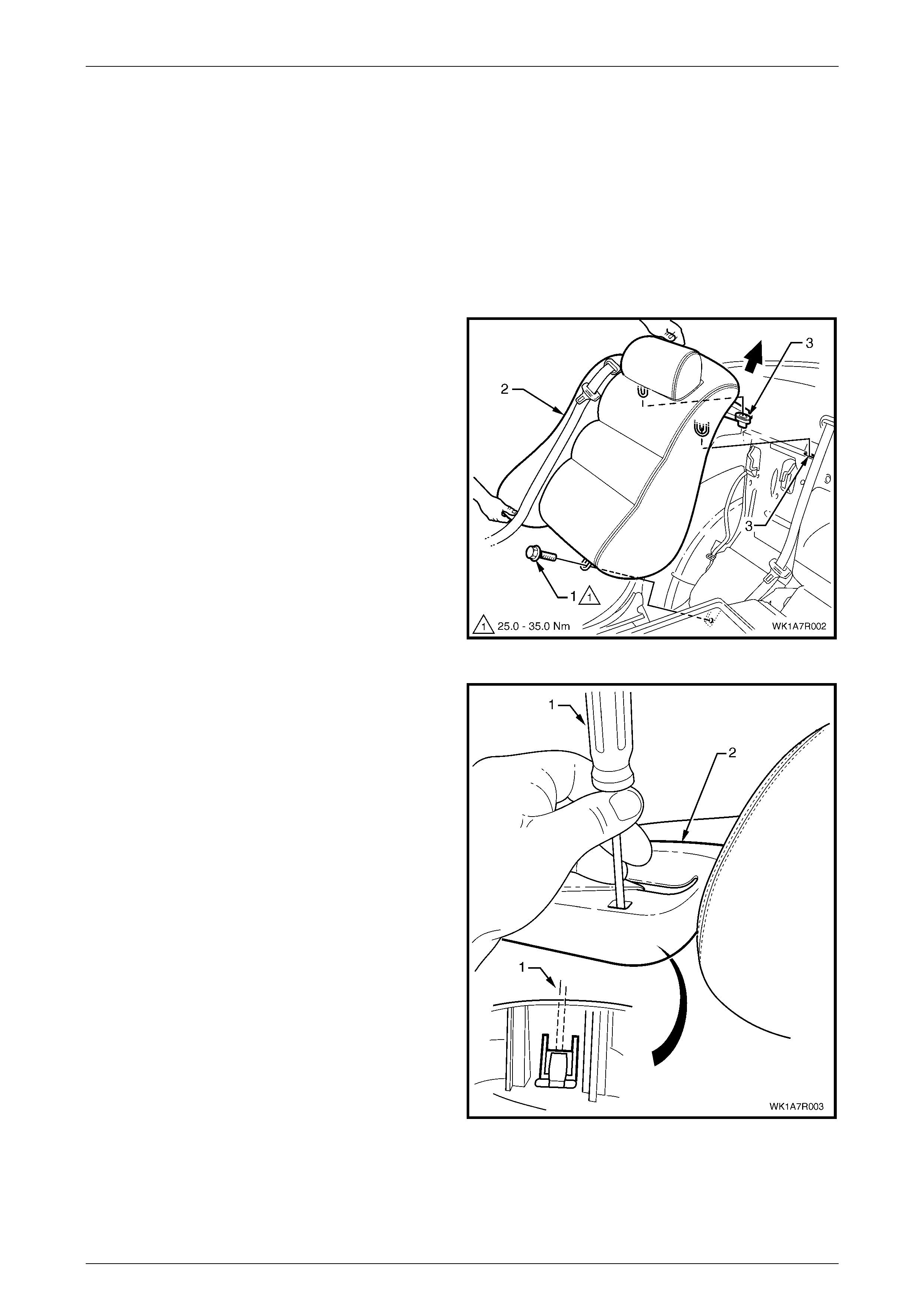
Seat Assemblies Page 1A7–359
Page 1A7–359
7.4 Rear Seat-back Assembly
LT Section No. – 14-325
Remove
1 If required, remove the following:
a Remove the rear seat cushion assembly, refer to 7.2 Rear Seat Cushion Assembly.
b Remove the lower seatbelt anchor bolt, refer to Section 12M, 2.1 Rear Seatbelt Assembly – Outboard.
2 Remove the bolt (1), retaining the rear seat-back
assembly (2) t o the vehicle.
3 Lift the rear seat-back assembly up and out of the Two
retaining brackets (3).
Figure 1A7 – 273
4 Insert a suitable screwdriver (1) into the seatbelt
escutcheon (2) and while applying a slight upward
pressure, push the retaining clip in to release the
escutcheon.
5 Remove the seat belt and escutcheon from the rear
seat-back assembly by feeding it through the opening
in the rear seat-back assembly.
6 Remove the rear seat-back assembly and repeat for
the opposite side if required.
Figure 1A7 – 274
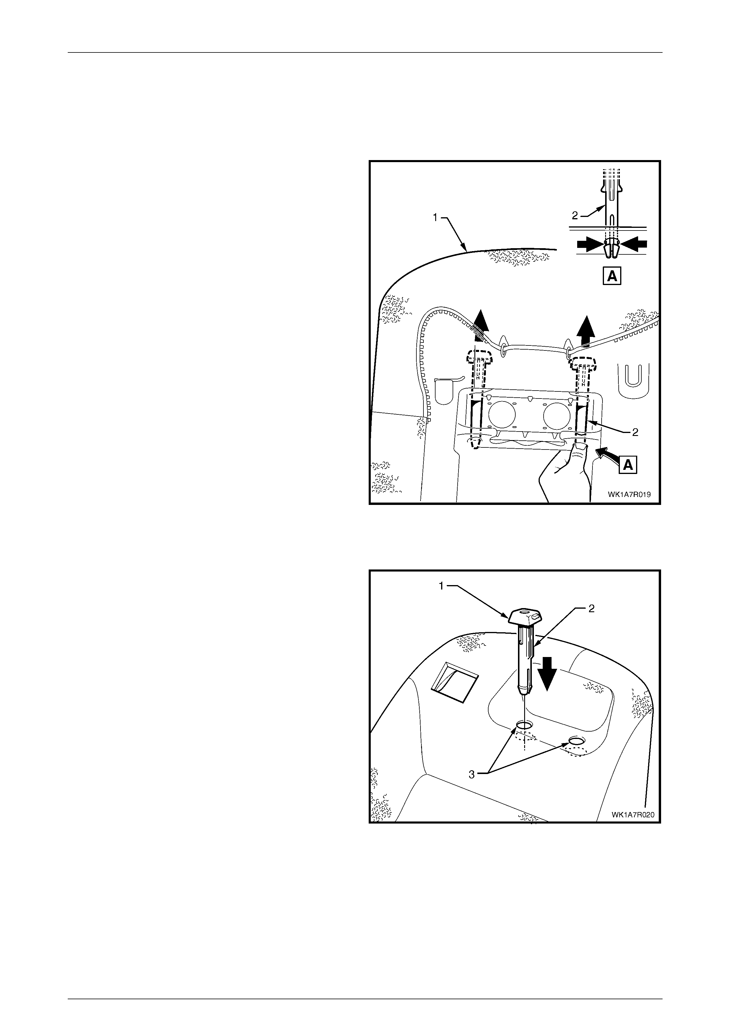
Seat Assemblies Page 1A7–360
Page 1A7–360
Head Restraint Sleeve
Remove
If required, remove the rear seat-back head restraint, refer to 7.3 Rear Seat-back Head Restraint Assembly Right and
Left-hand Side.
1 From the back of rear seat-back (1) (foam side),
squeeze the head restraint sleeve locating prongs (2)
together and remove the sleeve up and out of the
seat-back assembly.
2 Repeat this process for the remaining head restraint
sleeve.
Figure 1A7 – 275
Reinstall
1 Reinstallation of the rear seat head restraint sleeve is
the reverse of the removal procedure ensuring the
locating ribs (2) of the head restraint sleeve (1) aligns
with the key-way (3) in the seat-back frame.
NOTE
The release button in the right-hand sleeve and
the hole in the left-hand side sleeve should face
each other when installed correctly.
Figure 1A7 – 276
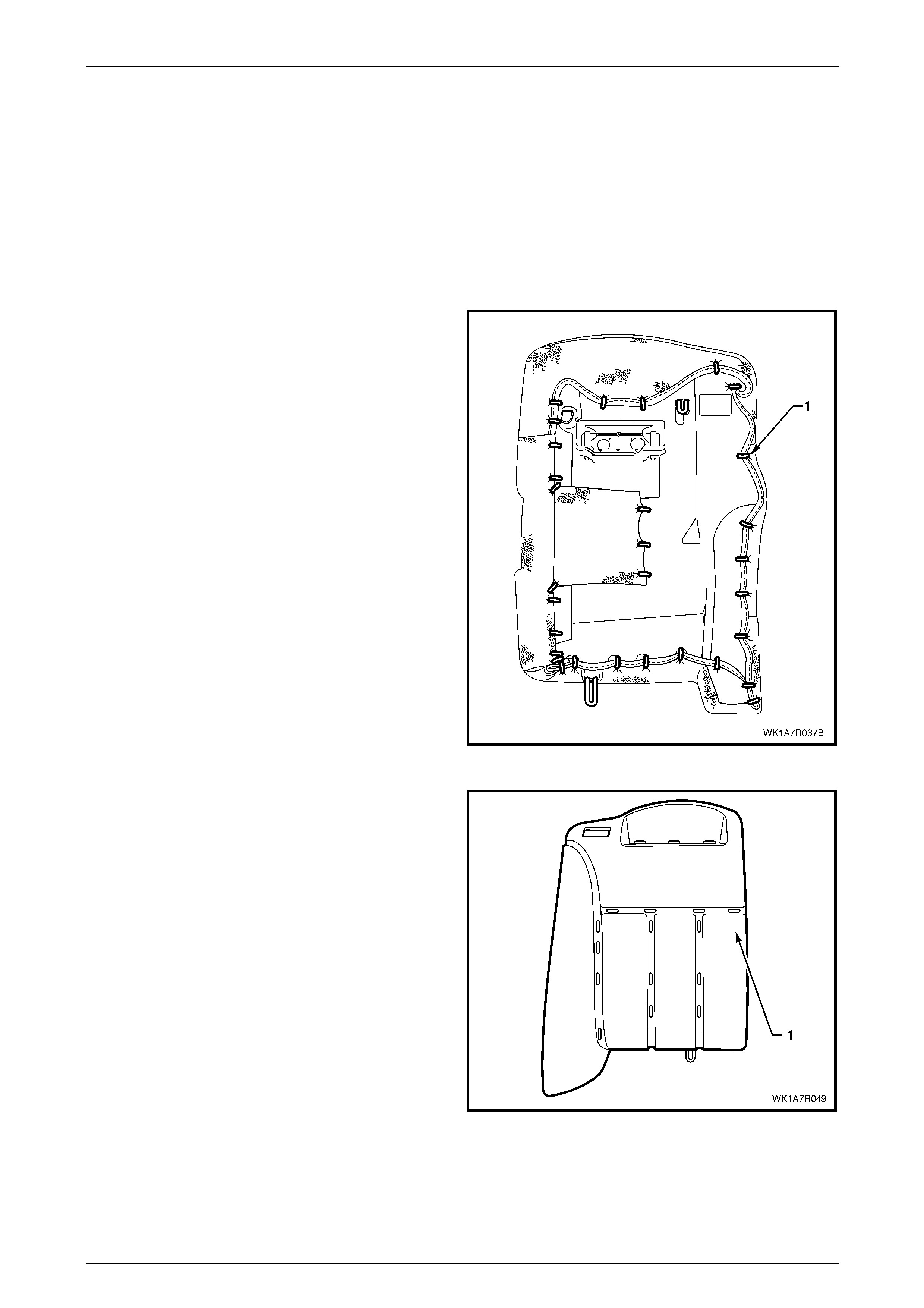
Seat Assemblies Page 1A7–361
Page 1A7–361
Rear Seat-back Cover
Rear Seat Type1
Surebond rear seat-back cover and pad are glued together as an assembly and are not serviced. If either the pad or the
cover requires replacement both will have to be replaced as a combined unit.
Rear Seat Type 2 and 5
Remove
1 Place the rear seat-back assembly face down.
2 Using bolt cutters or side cutters, remove
approximately 31 hog rings (1) attaching the cover to
the outer sections of the rear seat-back pad and frame
assembly in the locations shown.
NOTE
Care must be taken when removing the hog
rings, not to damage the rear seat-back cover.
All hog rings will be damaged in this operation
and will require replacement.
NOTE
The rear seat Type 5, right-hand side rear seat-
back assembly is fitted with a first aid kit pouch.
For rear seat Type 2, the hog rings used to
attach the first aid kit pouch are installed along
the inner edge of the rear seat-back cushion and
frame assembly .
Figure 1A7 – 277
3 Using the following sequence of operations continue
and cut the hog rings as they are revealed us ing bolt
cutters or side cutters at the locations shown.
Figure 1A7 – 278
4 Remove the head restraint sleeve, refer to Head Restraint Sleeve.
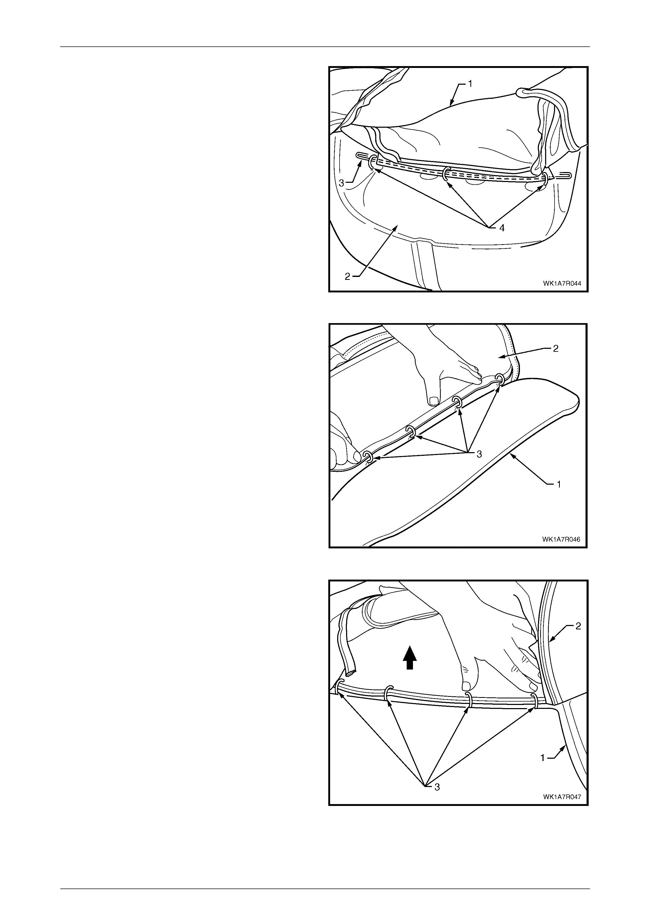
Seat Assemblies Page 1A7–362
Page 1A7–362
5 Fold the upper portion of the rear seat-back cover (1)
over the rear seat-back pad assembly (2).
6 Remove the head restraint reta ining wire (3) by cutting
the three hog rings (4).
Figure 1A7 – 279
7 While holding the rear seat-back pad assembly (1),
pull the outer edge of the cover (2) away from the rear
seat-back pad and cut the four hog rings (3) along the
outer groove.
Figure 1A7 – 280
8 While holding the seat-back pad assembly (1), fold the
top edge of the cover (2) over the top of the seat-back
assembly to reveal the four hog rings (3) in the upper
horizontal groove of the pad and cut to remove.
Figure 1A7 – 281
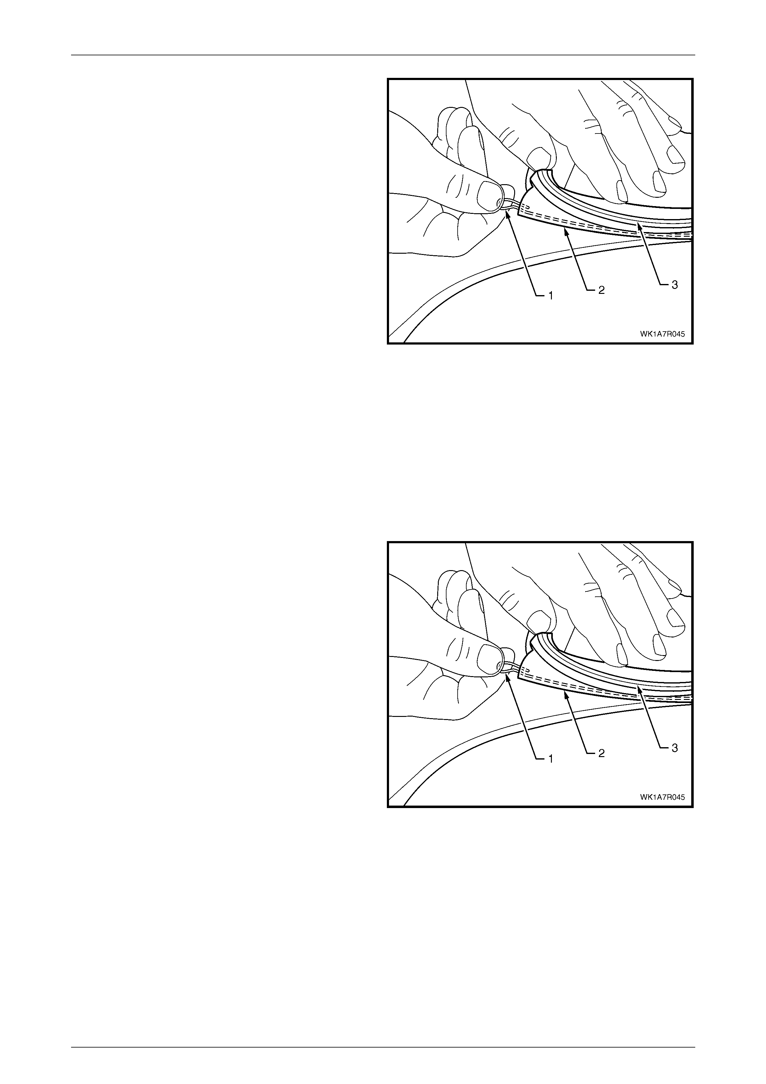
Seat Assemblies Page 1A7–363
Page 1A7–363
9 Remove the retaining wire (1) for the upper horizontal
groove from the casing (2) attached to the cover (3).
10 Continue to fold the cove r towards the centre of the
pad and cut the three hog rings from the centre
corresponding groove.
11 If required, remove the retaining wire from the casing
attached to the cover as in step 6.
12 Repeat the process for the remaining three hog rings
and retaining wire in the inner corresponding groove.
13 Remove the rear seat-back cover.
Figure 1A7 – 282
Reinstall
Using the follow ing seque nce of oper ati ons, align the rear seat-back cover to the pad assembly (1) and attach w ith
approximately 17 hog rings in the positions shown, refer to Figure 1A7 – 278.
NOTE
Ensure that the seat-back cover aligns with all
grooves in the pad before attaching with hog
rings.
1 If removed, reinstall the retaining wire (1) into the inner
groove casing (2) attached to the cover (3).
Figure 1A7 – 283
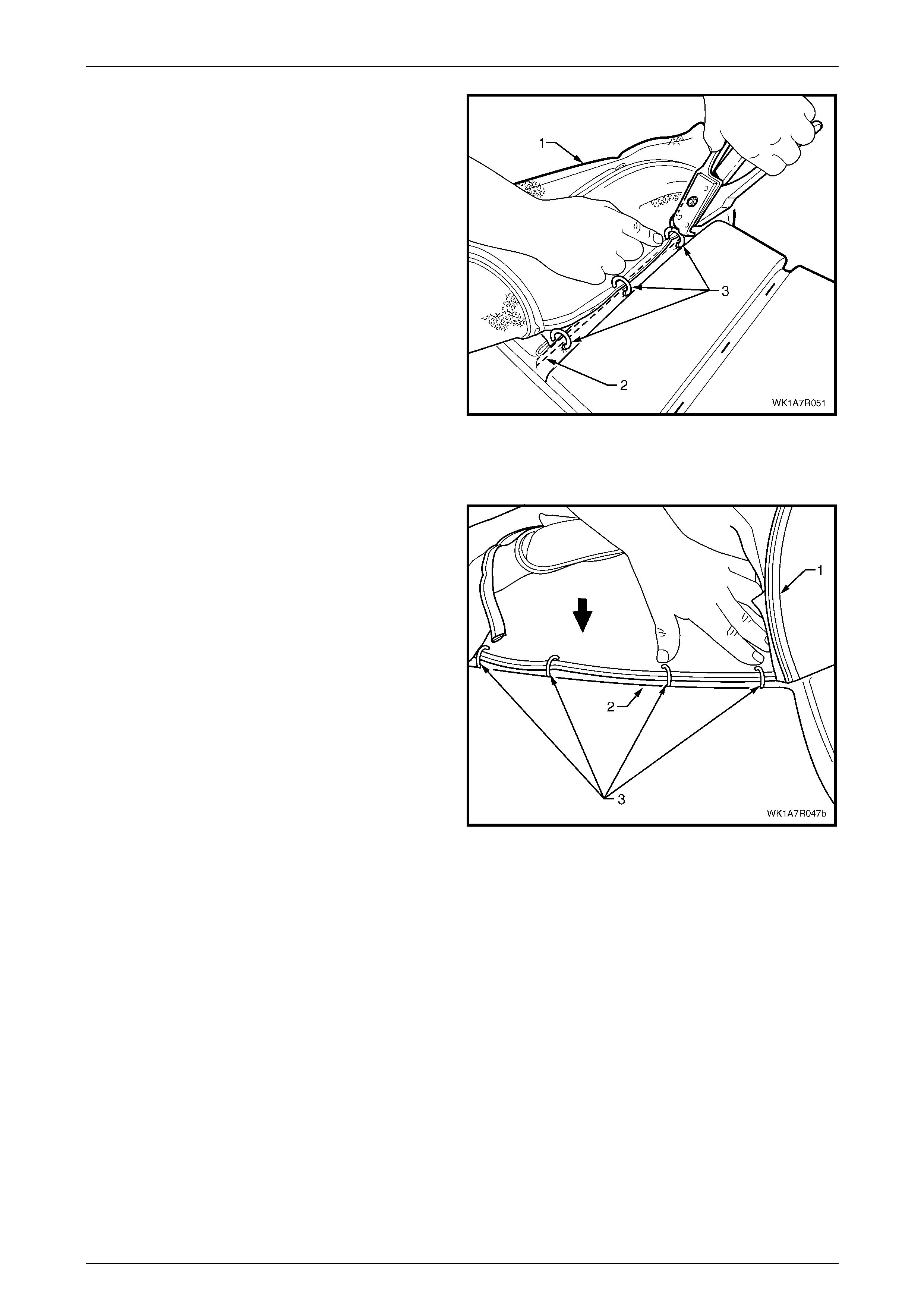
Seat Assemblies Page 1A7–364
Page 1A7–364
2 Align the cover (1) to the inner vertical corresponding
groove in the pad (2) and attach with three hog rings
(3), using hog ring pliers.
3 Repeat steps 1 and 2 for the centre vertical
corresponding groove.
Figure 1A7 – 284
4 If removed, reinstall the retaining wire (1) into the upper horizontal groove casing (2) attached to the cover (3), refer
to Figure 1A7 – 283.
5 Align the cover (1) to the upper horizontal groove (2)
and attach with four hog rings (3).
Figure 1A7 – 285
6 If removed, reinstall the retaining wire (1) into the outer groove casing (2) attached to the cover (3), refer to
Figure 1A7 – 283.
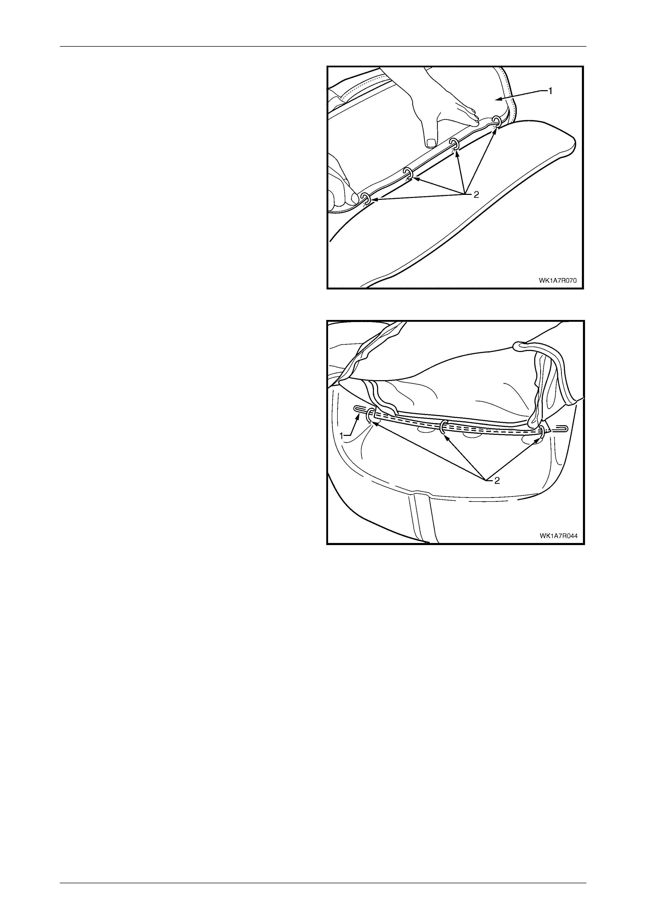
Seat Assemblies Page 1A7–365
Page 1A7–365
7 Align the cover (1) to the outer vertical groove in the
pad and attach with four hog rings (2).
Figure 1A7 – 286
8 Attach the restraint retaining wire (1) with three hog
rings (2) to the frame.
Figure 1A7 – 287
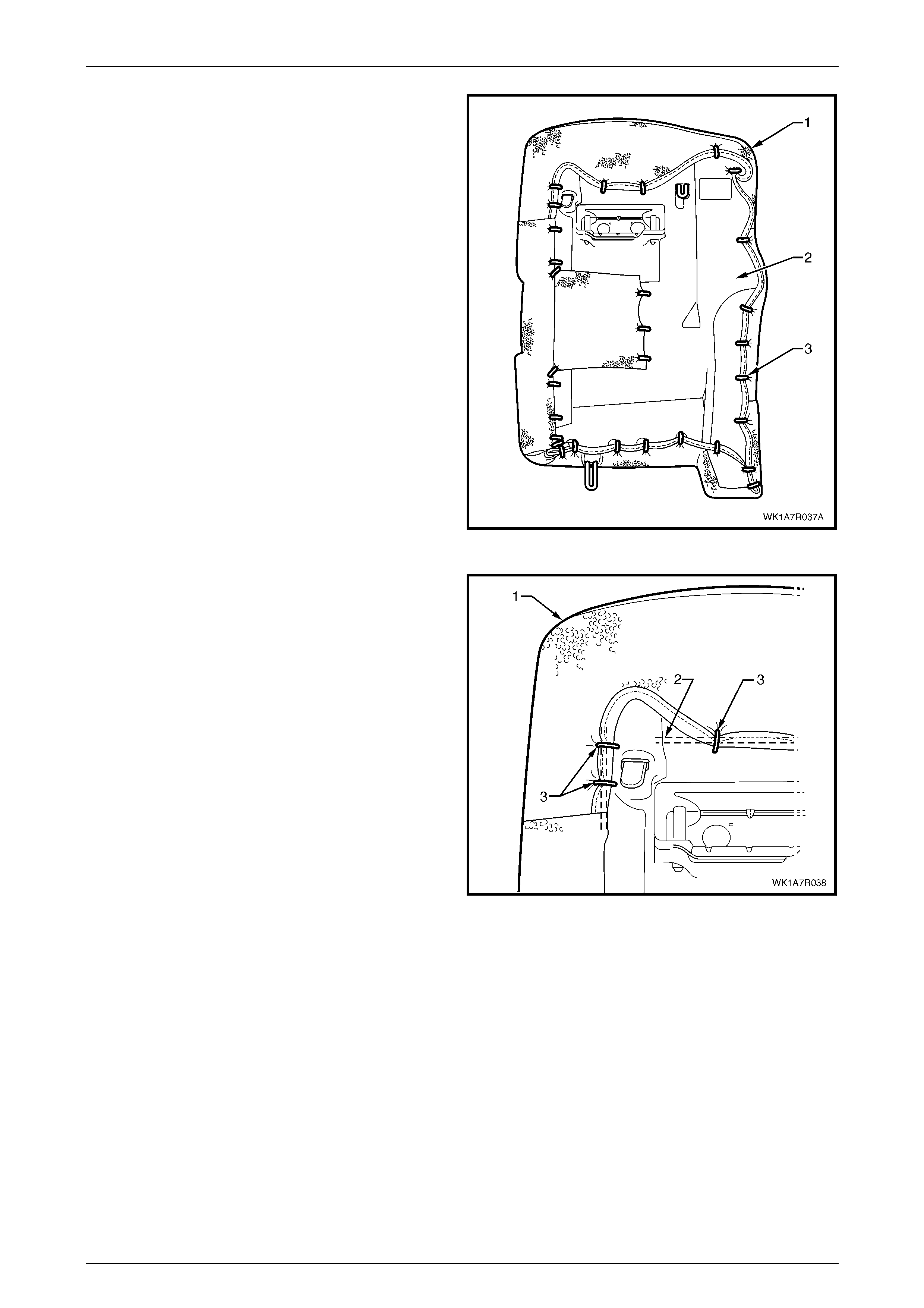
Seat Assemblies Page 1A7–366
Page 1A7–366
9 Place the seat-back as sembly face down on a clean
surface and using the following sequence of
operations, continue attaching the rear seat-back
cover (1) to the pad assembly (2) with hog rings (3),
approximately 31 places in the positions shown.
Figure 1A7 – 288
10 Starting at the upper inner corner of the rear
seat-back, pull the cover (1) over the corner and
attach to the wire frame (2) with three hog rings (3).
Figure 1A7 – 289
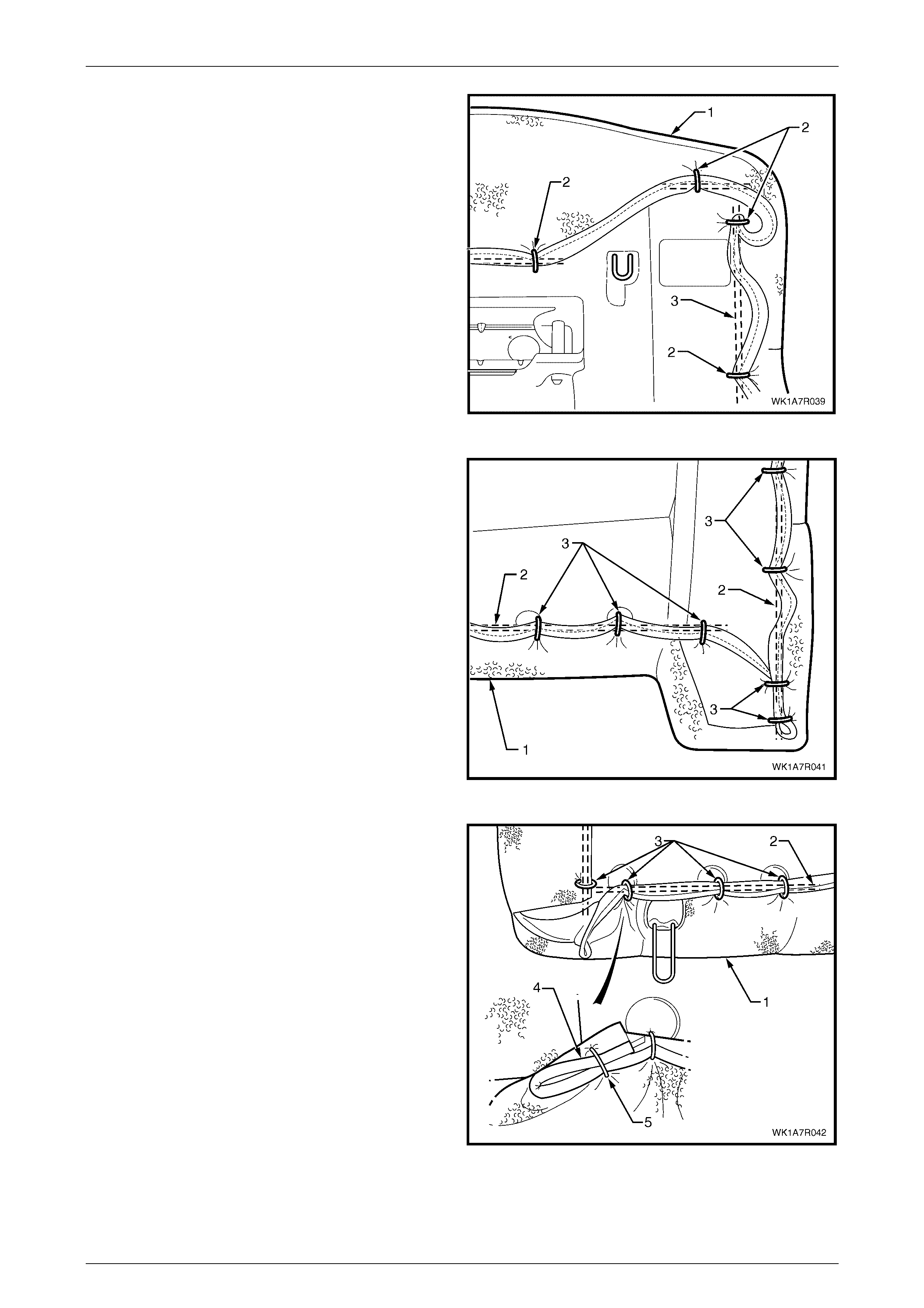
Seat Assemblies Page 1A7–367
Page 1A7–367
11 While pulling the outboard side corner of the cover (1)
over the top and towards the centre, fix with four hog
rings (2) to the wire frame (3).
Figure 1A7 – 290
12 Continue at the outboard lower corner and attach the
cover (1) to the frame (2), by pulling the cover tight
and fixing with seven hog rings (3).
Figure 1A7 – 291
13 Continue at the inner lower corner and attach the
cover (1) to the frame (2), by pulling the cover tight
and fixing with four hog rings (3).
14 Attach the seat-back cover lower piping overhang (4)
with one hog ring (5) back on to the lower piping.
Figure 1A7 – 292
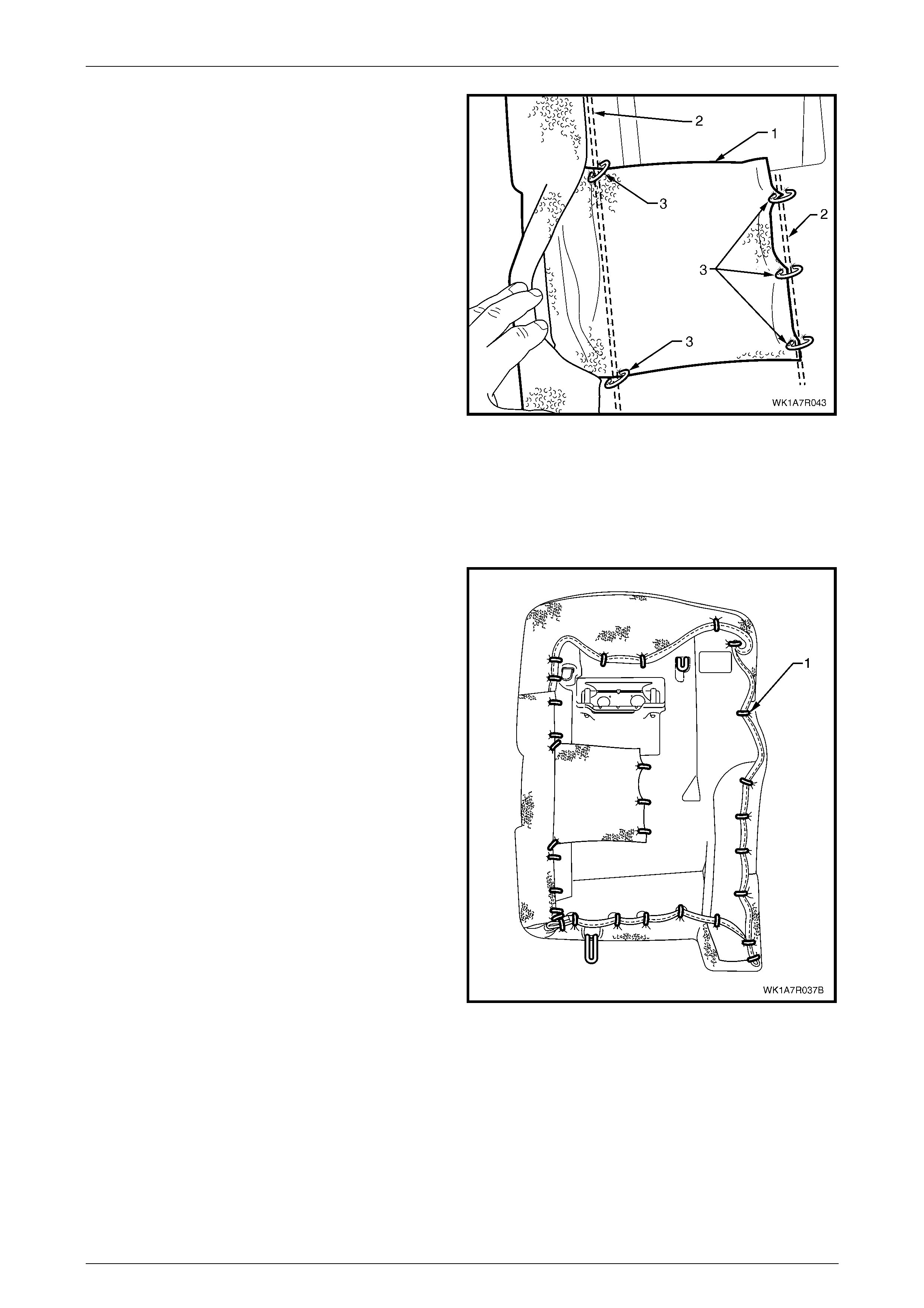
Seat Assemblies Page 1A7–368
Page 1A7–368
15 If fitted wi th a first aid kit pouch (1) attach the pouch to
the frame (2) with five hog rings (3).
NOTE
The rear seat Type 5, right-hand side rear seat-
back assembly is fitted with a first aid kit pouch.
For rear seat Type 2 rear seat-back assembly,
the hog rings used to attach the first aid kit
pouch are installed along the inner edge of the
rear seat-back cushion and frame assembly.
16 Continue along the inner edge and attach the cover to
the frame, by pulling the cover tight and fixing with a
further three hog rings.
NOTE
Ensure the cover is fitted neatly by hand into all
corners and contours of the rear seat-back pad
and is free from any creases.
Figure 1A7 – 293
Rear Seat Type 3 and 6
Remove
1 Place the rear seat-back assembly face down.
2 Using bolt cutters or side cutters, remove
approximately 31 hog rings (1) attaching the outer
sections of the cover to the rear seat-back pad and
frame assembly .
NOTE
Care must be taken when removing the hog
rings, not to damage the rear seat-back cover.
All hog rings will be damaged in this operation
and will require replacement.
NOTE
The rear seat Type 6, right-hand side rear seat-
back assembly is fitted with a first aid kit pouch.
For rear seat Type 3 rear seat-back assembly,
the hog rings used to attach the first aid kit
pouch are installed along the inner edge of the
rear seat-back cushion and frame assembly.
Figure 1A7 – 294
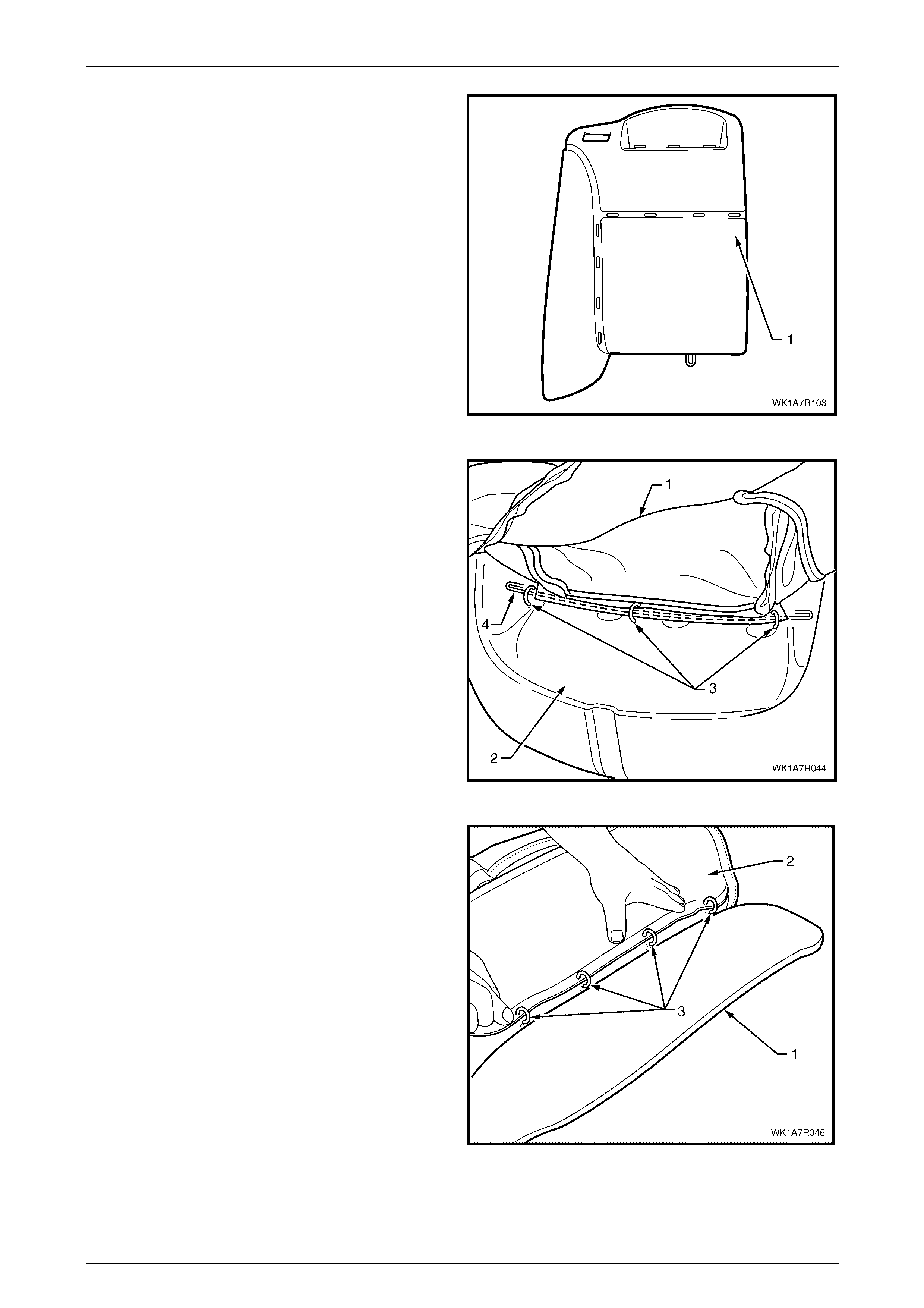
Seat Assemblies Page 1A7–369
Page 1A7–369
3 After removing the rear hog rings, continue with the
following sequence of operations and cut the hog rings
attaching the cover to the front side of the pad (1), as
they are revealed using bolt cutters or side cutters at
the locations shown.
Figure 1A7 – 295
4 Fold the upper portion of the rear seat-back cover (1)
over the rear seat-back pad assembly (2) and remove
the three hog rings (3) attaching the head restraint
retaining wire (4).
Figure 1A7 – 296
5 While holding the rear seat-back pad assembly (1),
pull the outer edge of the cover (2) away from the rear
seat-back pad and cut the four hog rings (3) along the
outer groove.
Figure 1A7 – 297
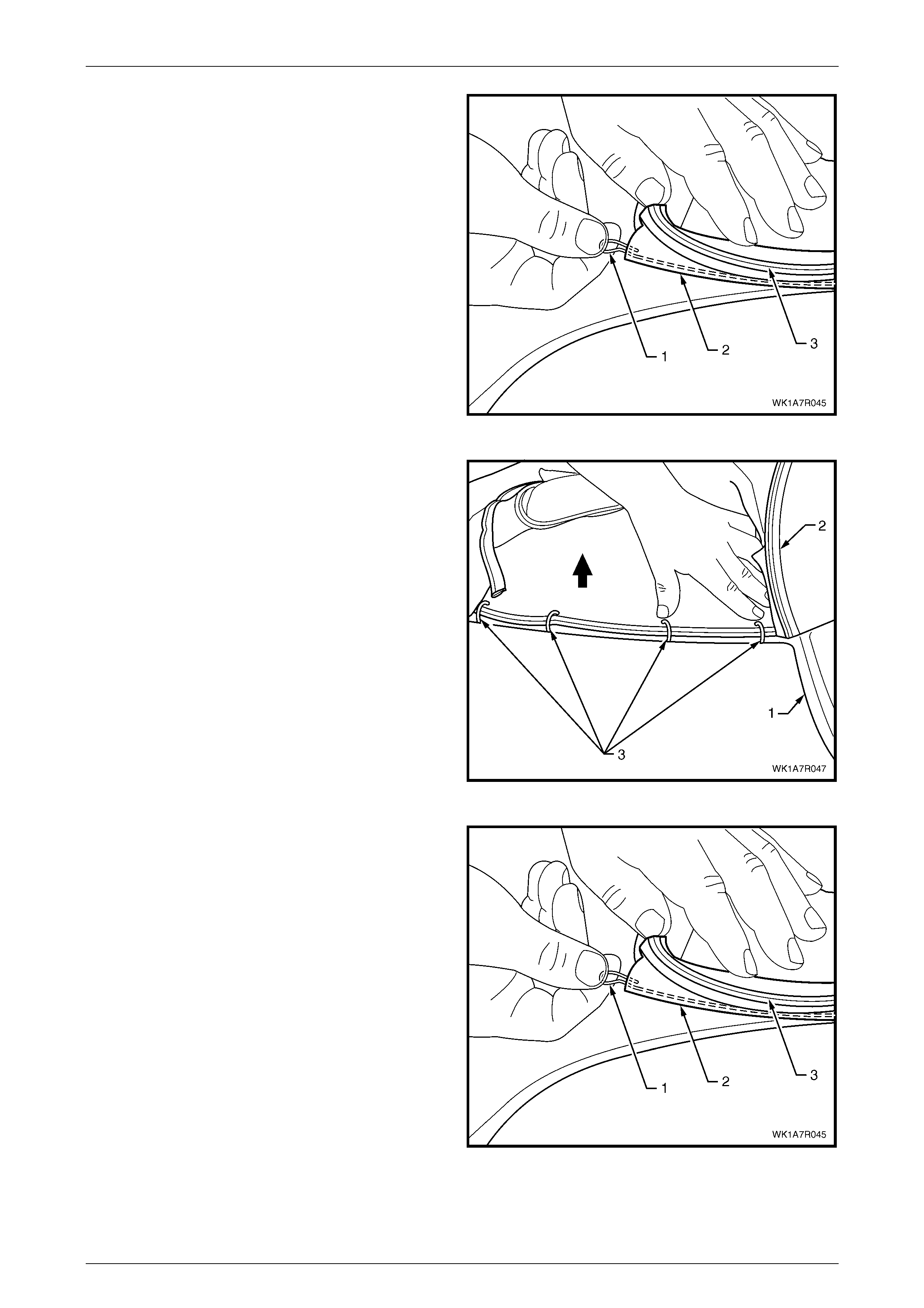
Seat Assemblies Page 1A7–370
Page 1A7–370
6 If required, remove the retaining wire (1) for the outer
groove from the casing (2) attached to the cover (3).
Figure 1A7 – 298
7 While holding the seat-back pad assembly (1), fold the
top edge of the cover (2) over to reveal the four hog
rings (3) in the upper horizontal groove of the pad and
cut the hog rings to remove.
Figure 1A7 – 299
8 Remove the retaining wire (1) for the upper horizontal
groove from the casing (2) attached to the cover (3)
and remove the rear seat-back cover from the pad
assembly.
Figure 1A7 – 300
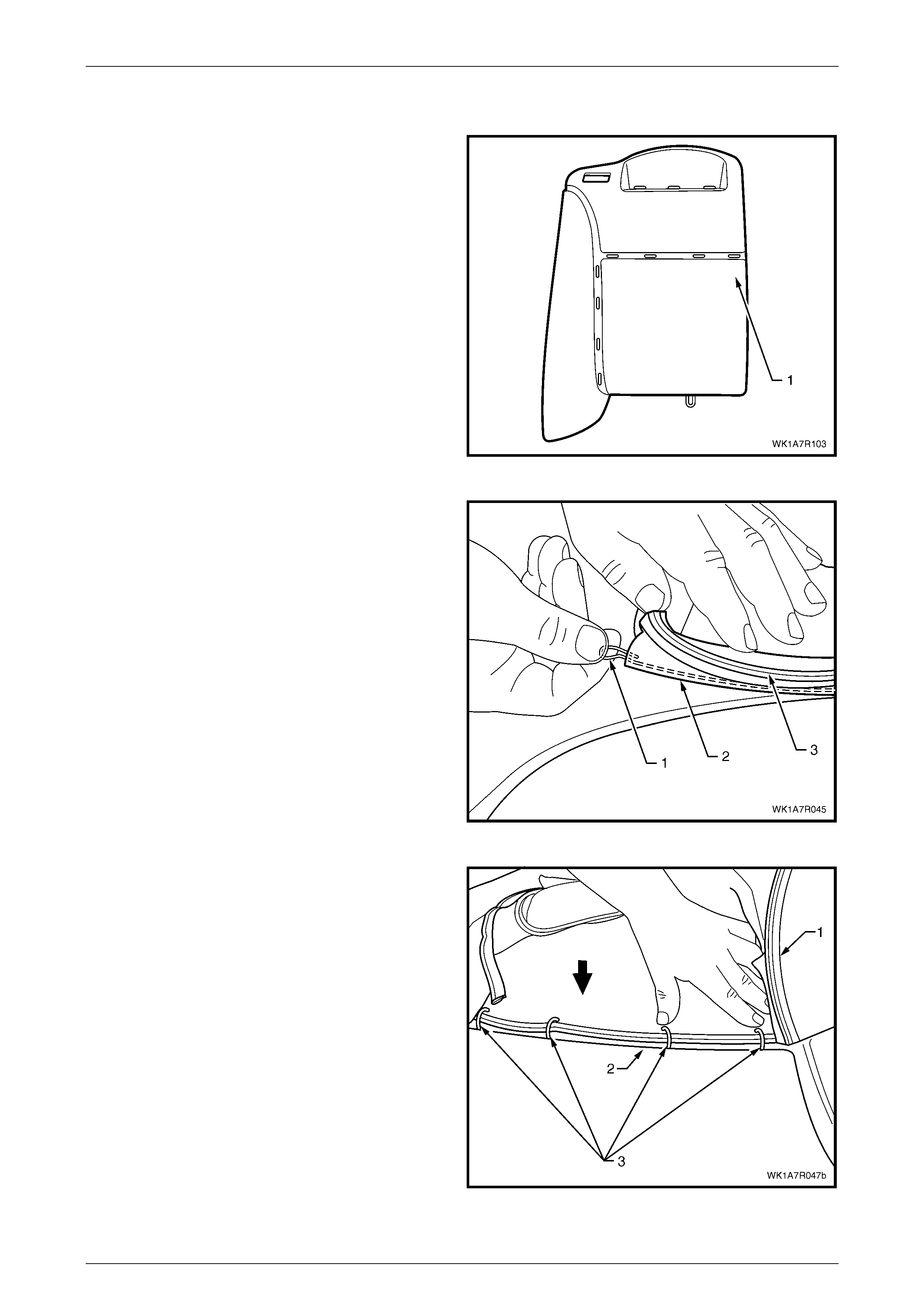
Seat Assemblies Page 1A7–371
Page 1A7–371
Reinstall
1 Using the following sequence of operations, align the
rear seat-back cover to the pad assembly (1) and
attach with approximately eight hog rings in the
position s show n.
NOTE
Ensure that the rear seat-back cover aligns with
the pad at all grooves before attaching hog rings.
Figure 1A7 – 301
2 Reinstall the retaining wire (1) into the upper horizontal
groove casing (2) attached to the cover (3).
Figure 1A7 – 302
3 Align the cover (1) to the upper horizontal groove (2)
and attach with four hog rings (3).
Figure 1A7 – 303
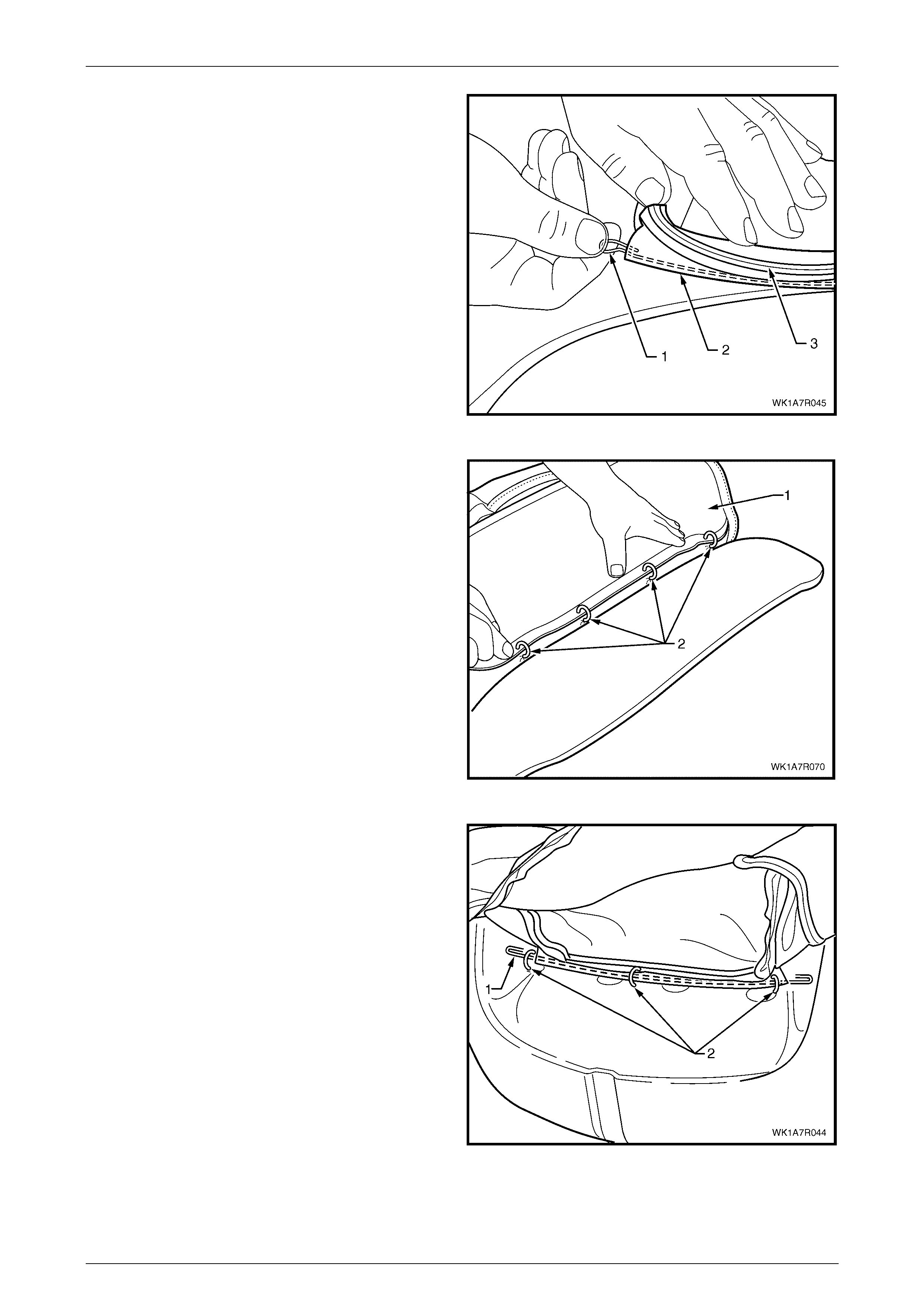
Seat Assemblies Page 1A7–372
Page 1A7–372
4 Reinstall the retaining wire (1) into the outer groove
casing (2) attached to the cover (3).
Figure 1A7 – 304
5 Align the cover (1) to the outboard vertical groove in
the pad and attach with four hog rings (2).
Figure 1A7 – 305
6 Attach the head restraint retaining wi re (1) with three
hog rings (2) to the frame.
Figure 1A7 – 306
7 Place the seat-back assem bly face down on a clean surface and usin g the following sequence of operation s,
continue attaching the rear seat-back cover (1) to the pad assembly (2) with hog rings (3), approximately 31 places
in the positions shown, refer Figure 1A7 – 294.

Seat Assemblies Page 1A7–373
Page 1A7–373
8 Starting at the upper inboard corner of the rear
seat-back, pull the cover (1) over the corner and
attach to the wire frame (2) with three hog rings (3).
Figure 1A7 – 307
9 While pulling the outboard side corner of the cover (1)
over the top and towards the centre, fix with four hog
rings (2) to the wire frame (3).
Figure 1A7 – 308
10 Continue at the outboard lower corner and attach the
cover (1) to the frame (2), by pulling the cover tight
and fixing with seven hog rings (3).
Figure 1A7 – 309
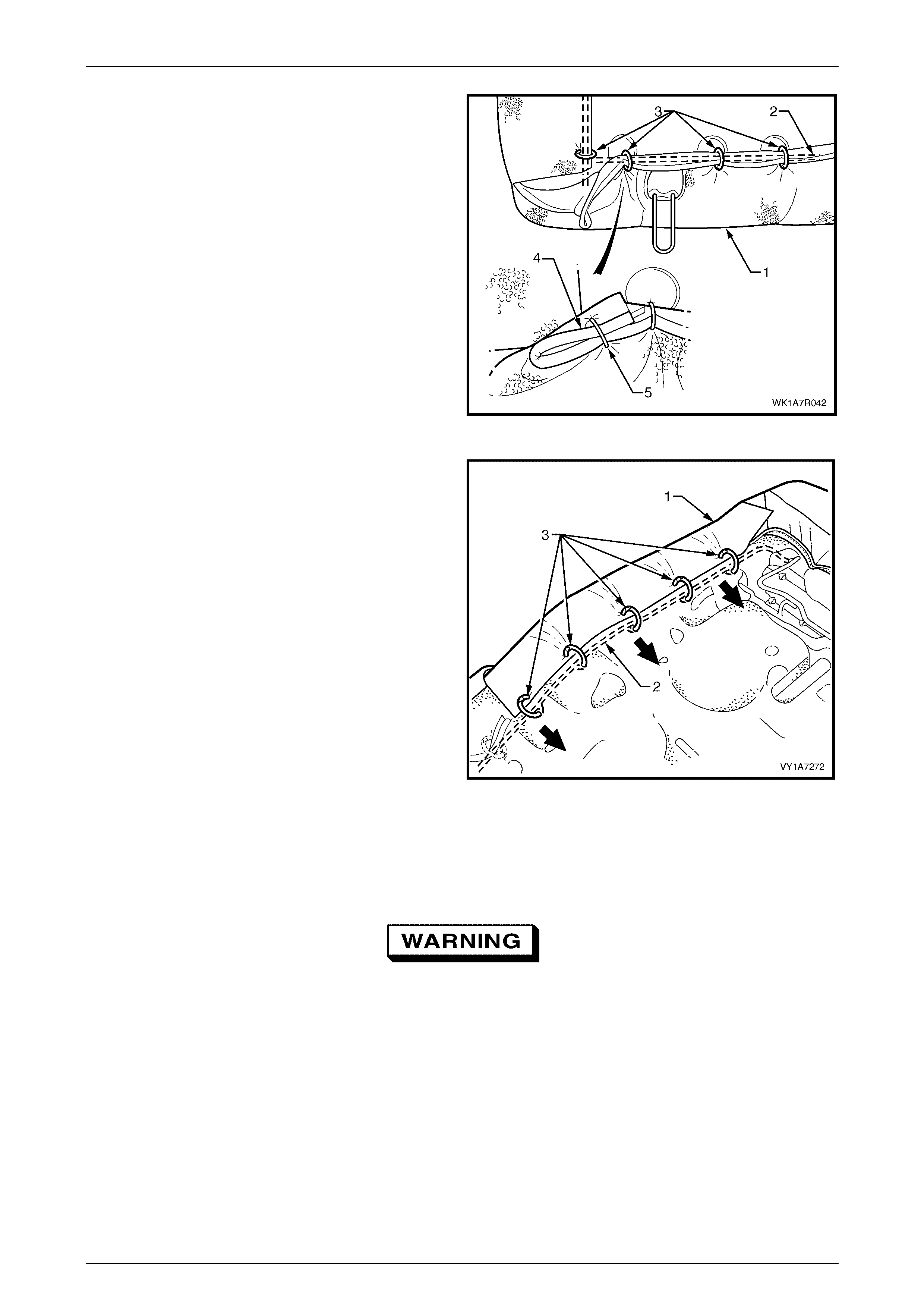
Seat Assemblies Page 1A7–374
Page 1A7–374
11 Continue at the inboard lower corner and attach the
cover (1) to the frame (2), by pulling the cover tight
and fixing with four hog rings (3).
12 Attach the seat-back cover lower piping overhang (4)
with one hog ring (5) back on to the lower piping.
Figure 1A7 – 310
13 Continue along the inboard edge and attach the cover
to the frame, by pulling the cover tight and fixing with a
further three hog rings.
Figure 1A7 – 311
Rear Seat Type 4
Remove
Safety glasses and work gloves must be worn
at all times when removing the hog rings.
NOTE
The following procedures are applicable to both
left and right-hand rear seat-back assemblies.
1 Place the rear seat-back assembly face down.

Seat Assemblies Page 1A7–375
Page 1A7–375
2 Using bolt cutters or side cutters, remove
approximately 31 hog rings (1) attaching the outer
sections of the cover to the rear seat-back pad and
frame assembly .
NOTE
Care must be taken when removing the hog
rings, not to damage the rear seat-back cover.
All hog rings will be damaged in this operation
and will require replacement.
3 Remove the rear head restraint sleeve, refer to
Head Restra int Sleeve.
Figure 1A7 – 312
4 After removing the rear hog rings, continue with the
following sequence of operations and cut the hog rings
attaching the cover to the front side of the pad (1), as
they are revealed using bolt cutters or side cutters at
the locations shown.
Figure 1A7 – 313
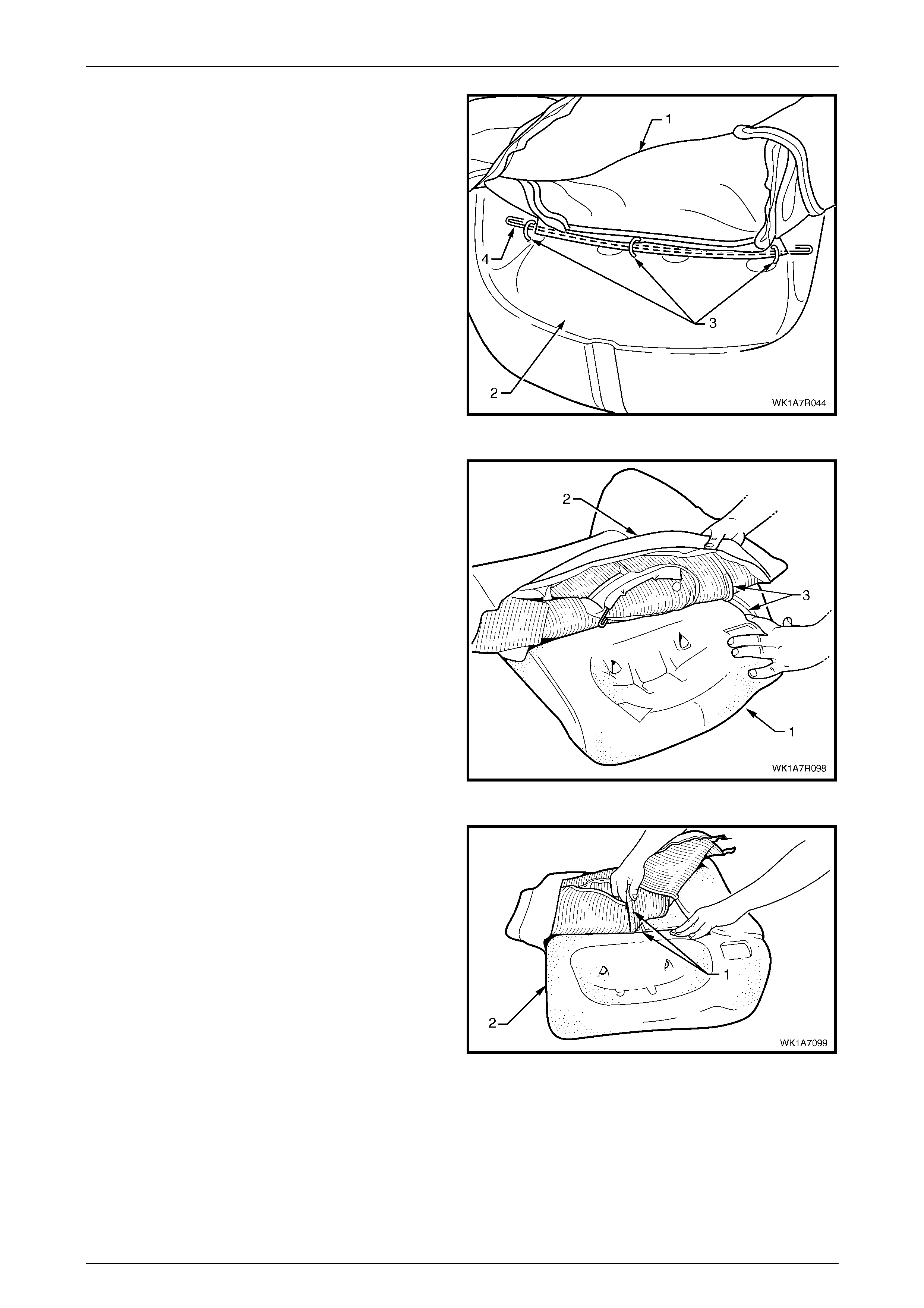
Seat Assemblies Page 1A7–376
Page 1A7–376
5 Fold the upper portion of the rear seat-back cover (1)
over the rear seat-back pad assembly (2).
6 Cut the three hog rings (3) attaching the retaining wire
(4) to the frame assembly.
Figure 1A7 – 314
7 While holding the rear seat-back pad assembly (1),
pull the upper corner of the cover (2) away from the
rear seat-back pad to disengage the hook and loop
strip (3).
Figure 1A7 – 315
8 Remove the one or two cross hook and loop strips (1)
while holding the rear seat-back pad (2).
Figure 1A7 – 316
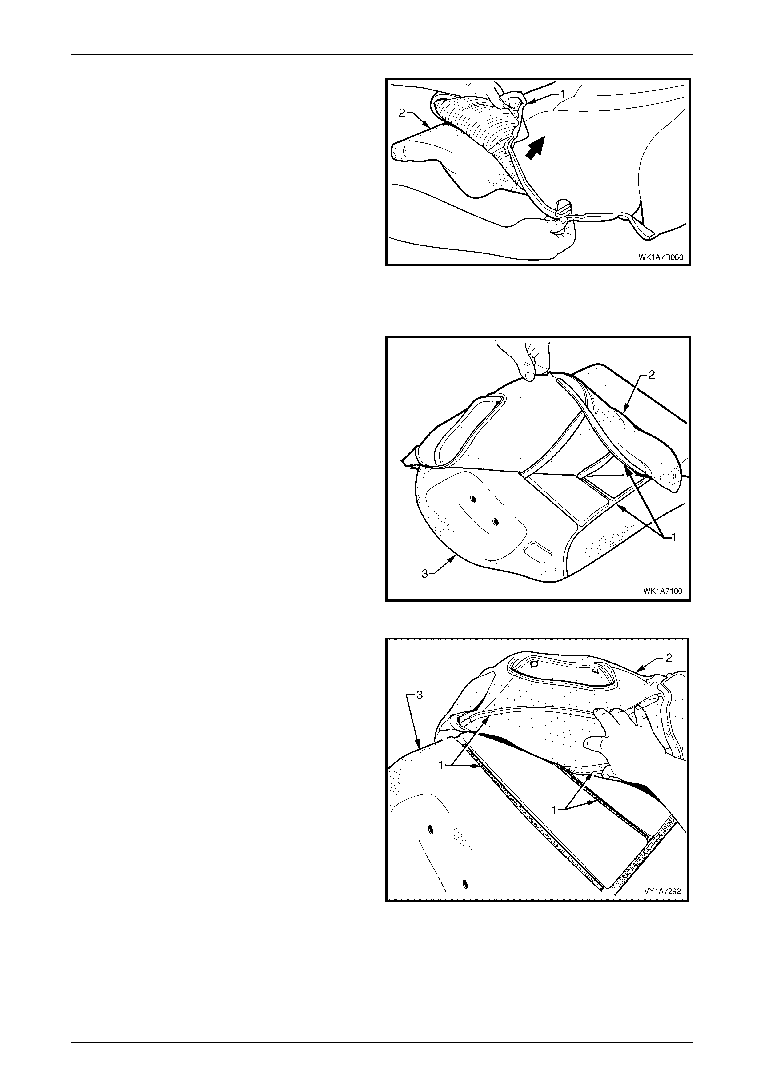
Seat Assemblies Page 1A7–377
Page 1A7–377
9 Fold the lower corner of the cover (1) over the seat-
back pad (2).
10 Remove the rear seat-back cover.
Figure 1A7 – 317
Reinstall
1 Align the outer hook and loop strip (1) on the seat-
back cover (2), with the rear seat-back pad (3).
Figure 1A7 – 318
2 Align the two cross hook and loop strips (1), on the
rear seat-back cover (2), with the rear seat -back pad
(3).
Figure 1A7 – 319
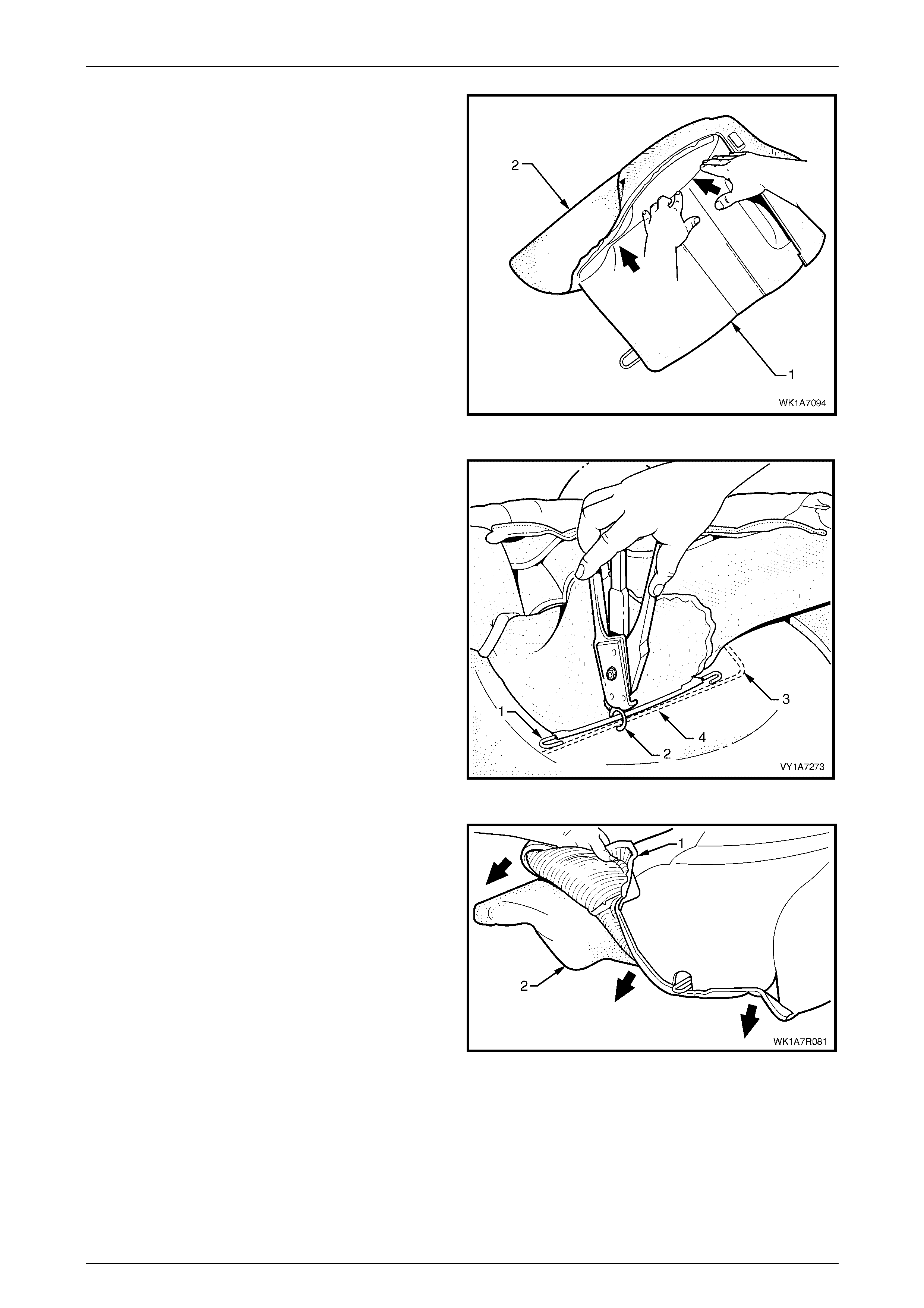
Seat Assemblies Page 1A7–378
Page 1A7–378
3 Press the folded edge of the rear seat-back cover (1)
firmly into the corresponding groove in the seat-back
pad (2) to engage the hook and loop strip.
Figure 1A7 – 320
4 Attach the head restraint retaining wire (1) with hog
ring (2), three places to the frame (3) using hog ring
pliers.
Figure 1A7 – 321
5 Roll the lowe r corner of the cover (1) over the rear
seat-back pad (2).
6 Roll the sides of the cover over the seat-back pad.
7 Roll the upper corners of the cover over the seat-back
pad.
NOTE
Make sure the cover is fitted neatly by hand into
all corners and contours of the seat back-pad.
Figure 1A7 – 322

Seat Assemblies Page 1A7–379
Page 1A7–379
8 Using the following sequence of operations, attach the
rear seat-back cover (1) to the rear seat-back pad and
frame assembly (2), with approximately 31 hog rings
(3), in the positions shown.
Figure 1A7 – 323
9 Starting at the upper outboard corner of the rear
seat-back, pull the cover (1) over the corner and
attach to the wire frame (2) with three hog rings (3).
Figure 1A7 – 324

Seat Assemblies Page 1A7–380
Page 1A7–380
10 While pulling the outboard side corner of the cover (1)
over the top and towards the centre, fix with four hog
rings (2) to the wire frame (3).
Figure 1A7 – 325
11 Continue at the outboard lower corner and attach the
cover (1) to the frame (2), by pulling the cover tight
and fixing with seven hog rings (3).
Figure 1A7 – 326
12 Continue at the inboard lower corner and attach the
cover (1) to the frame (2), by pulling the cover tight
and fixing with four hog rings (3).
13 Attach the seat-back cover lower piping overhang (4)
with one hog ring (5) back on to the lower piping.
Figure 1A7 – 327
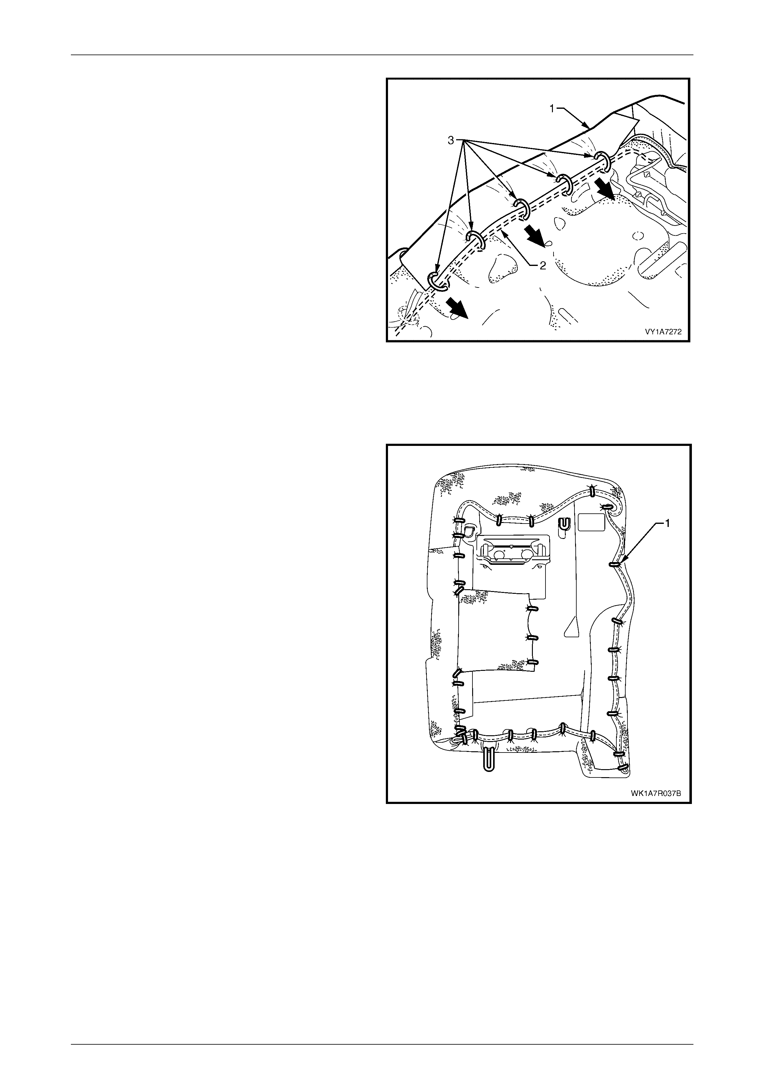
Seat Assemblies Page 1A7–381
Page 1A7–381
14 Continue attaching the cover (1) to the frame (2), by
pulling the cover tight and fixing with five hog rings (3).
Figure 1A7 – 328
Rear Seat Type 7 and 8
Remove
1 Place the seat-back as sembly face down on a clean
surface.
2 Using the following sequence of operations, use bolt
cutters or side cutters to remove approximatel y 31 hog
rings (1) attaching the outer sections of the cover to
the rear seat-back pad and frame as sembly in the
position s show n.
NOTE
Care must be taken when removing the hog
rings, not to damage the rear seat-back cover.
All hog rings will be damaged in this operation
and will require replacement.
Figure 1A7 – 329
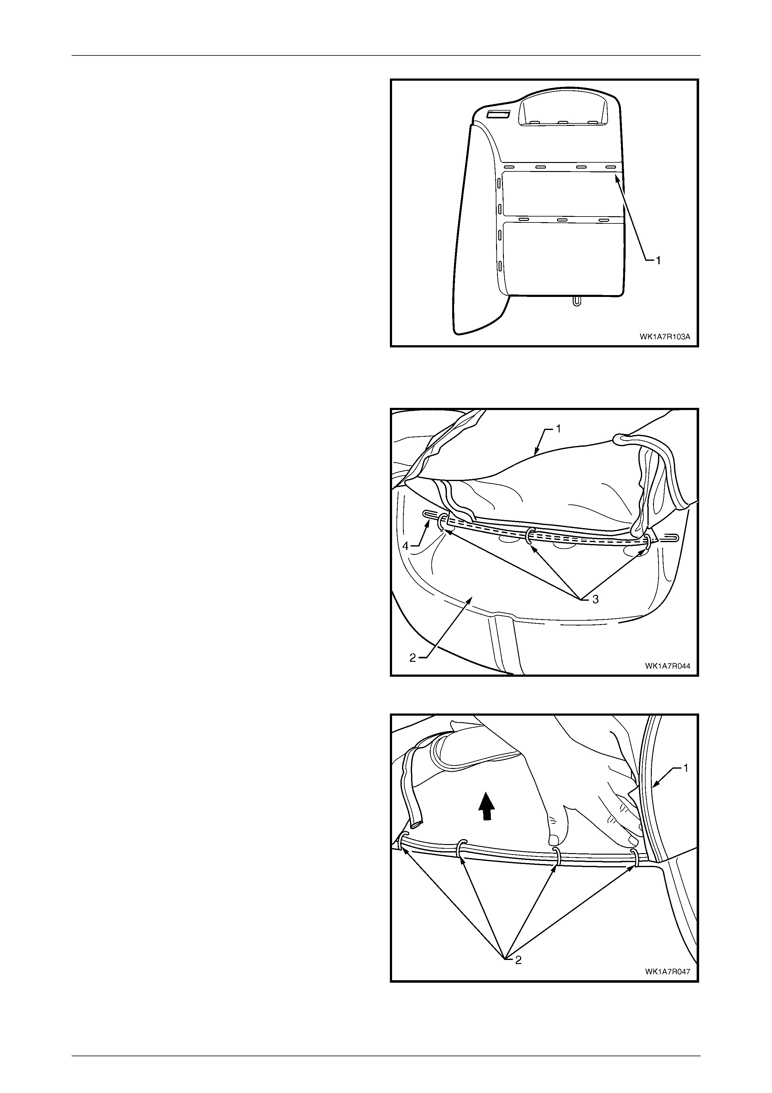
Seat Assemblies Page 1A7–382
Page 1A7–382
3 Continue to remove the rear seat-back cover from the
front of the pad assembly (1) by cutting the 11 hog
rings as they are revealed using bolt cutters or side
cutters.
Figure 1A7 – 330
4 Remove the head restraint sleeves, refer to Head Restraint Sleeve.
5 Fold the upper portion of the rear seat-back cover (1)
over the rear seat-back pad assembly (2).
6 Cut the three hog rings (3) attaching the retaining wire
(4) to the frame assembly.
Figure 1A7 – 331
7 Fold the cover (1) over the top to reveal the four hog
rings (2) in the continuation of the outer groove
running across the top of the pad and cut the hog rings
to remove.
Figure 1A7 – 332
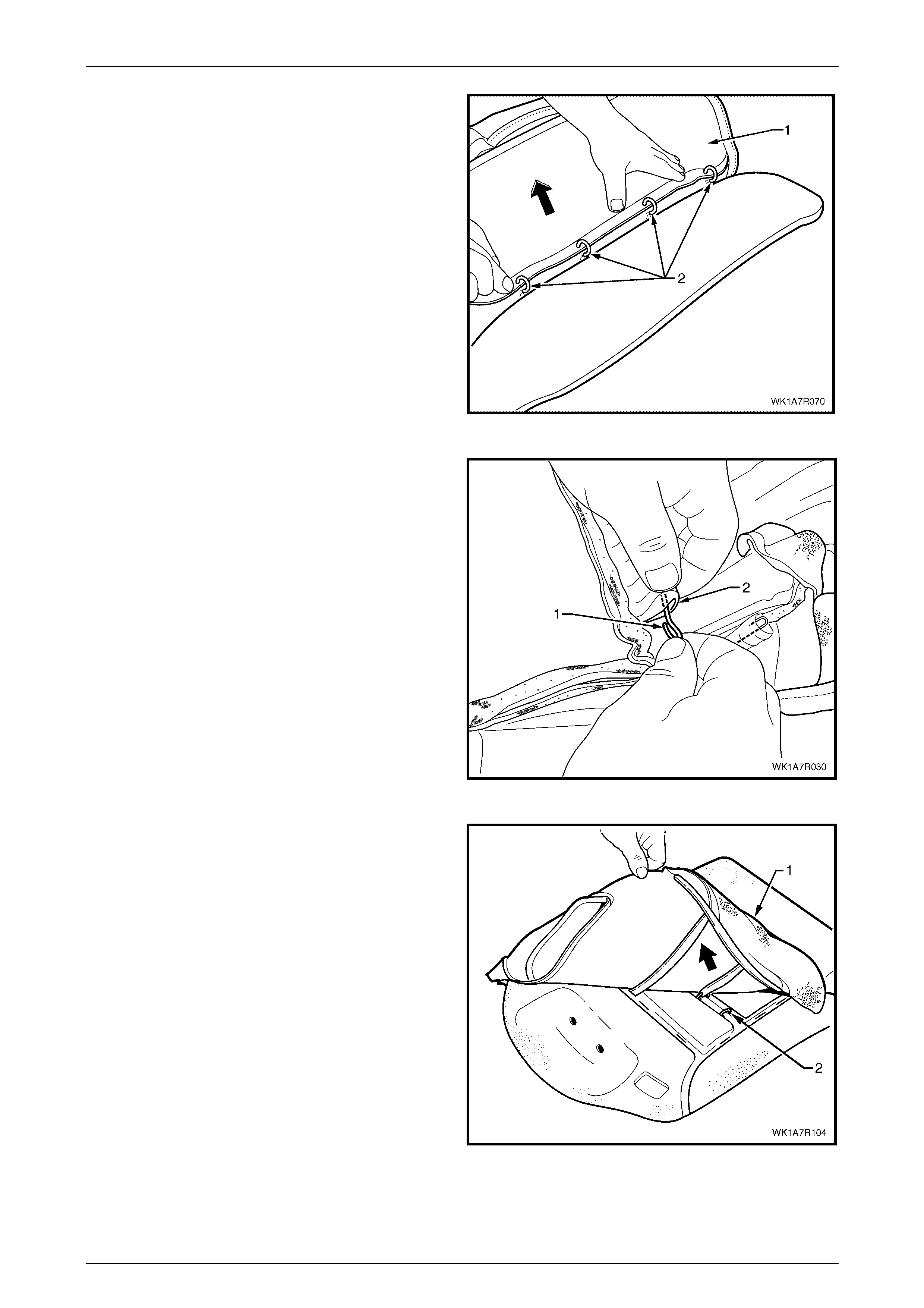
Seat Assemblies Page 1A7–383
Page 1A7–383
8 While holding the rear seat-back pad assembly (1),
pull the outboard edge of the cover away from the rear
seat-back pad and cut the four hog rings (2) along the
outer groove.
Figure 1A7 – 333
9 If required, remove the retaining wire (1) from the
casing (2) attached to the cover.
Figure 1A7 – 334
10 Continue to fold the rear seat-back cover (1) towards
the centre revealing the outer hog ring (2) in the lower
horizontal groove.
11 Cut the outer hog ring and continue until all three hog
rings have been removed.
Figure 1A7 – 335
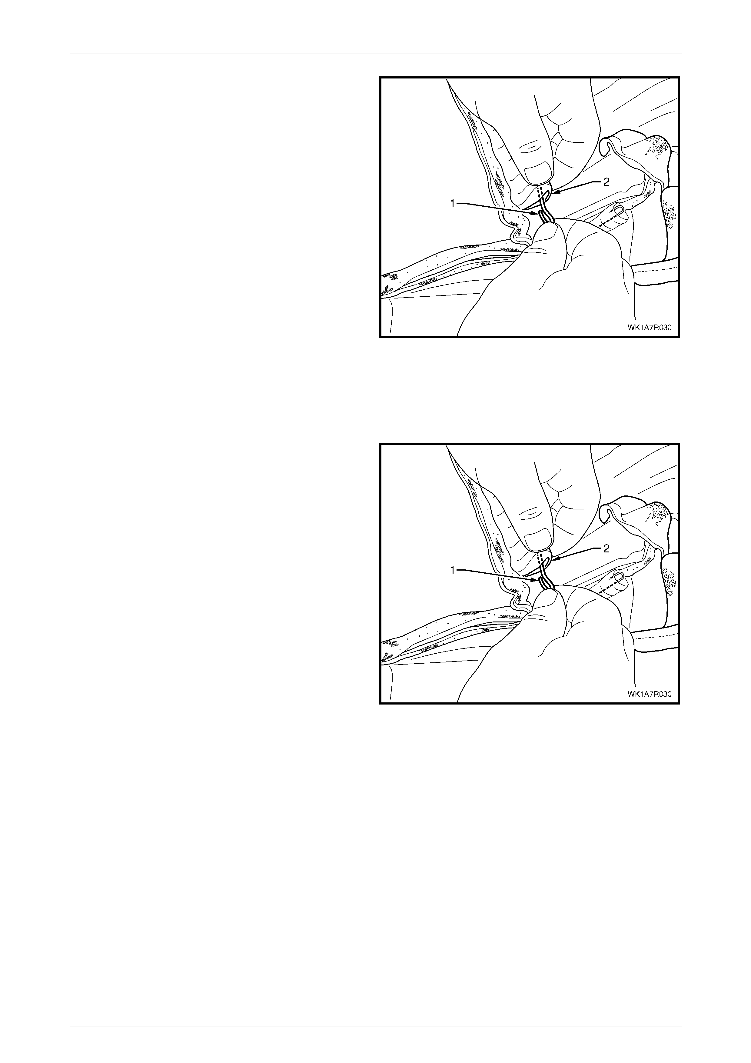
Seat Assemblies Page 1A7–384
Page 1A7–384
12 If required, remo ve the retaining wire (1) from the
casing (2) attached to the cover.
13 Remove the rear seat-back cover.
Figure 1A7 – 336
Reinstall
1 Using the following seque nce of oper ati ons, align the rear se at-back cover to the pad assembly (1) and attach with
11 hog rings in the locations shown, refer Figure 1A7 – 330
2 Reinstall the retaining wire (1) into the lower horizontal
groove casing (2) attached to the cover.
Figure 1A7 – 337
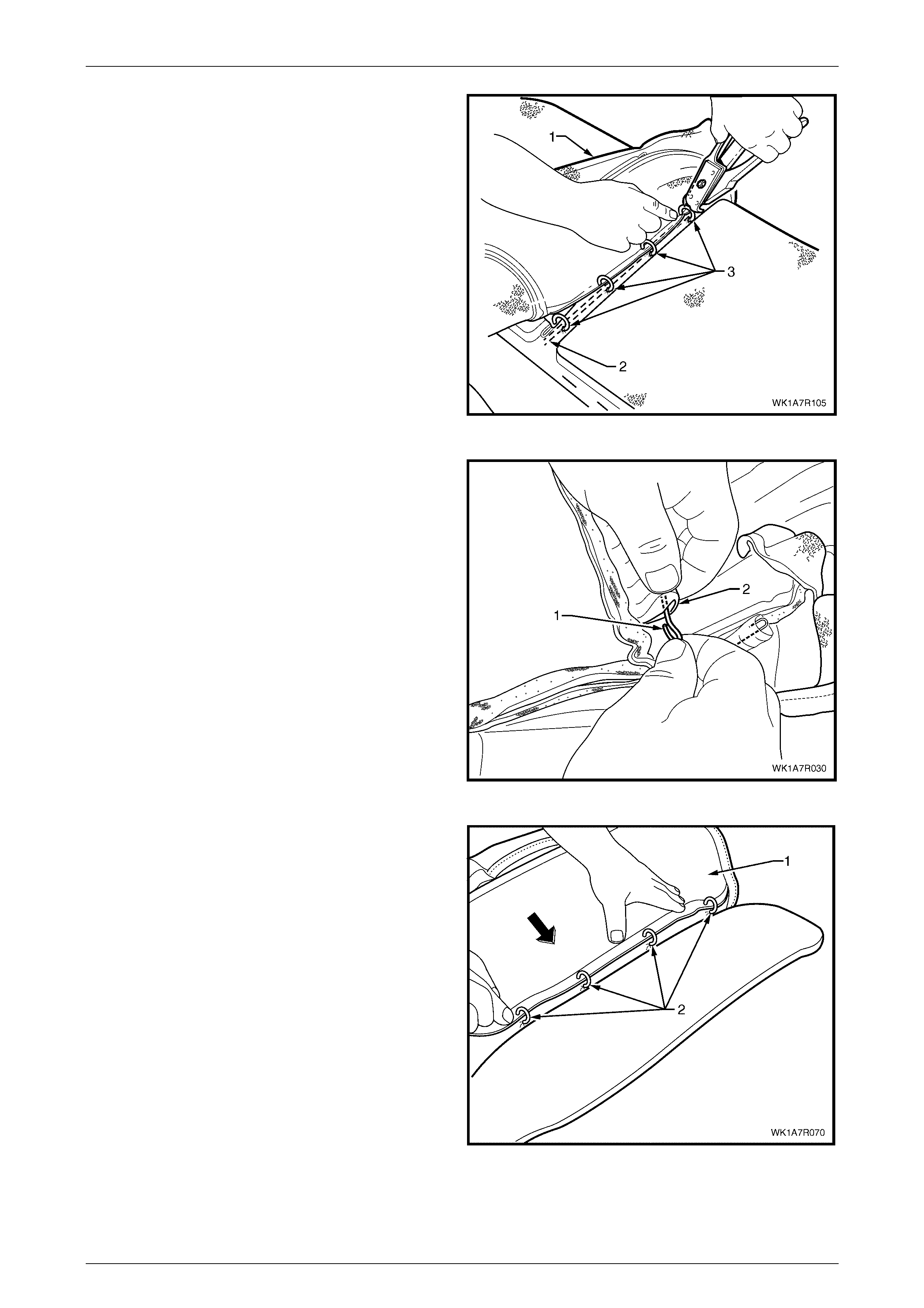
Seat Assemblies Page 1A7–385
Page 1A7–385
3
A
lign the cover (1) to the lower horizontal groove in the
pad (2) and attach with four hog rings (3), using hog
ring pliers.
Figure 1A7 – 338
4 Reinstall the retaining wire (1) into the outer groove
casing (2) attached to the cover.
Figure 1A7 – 339
5 Align the cover (1) to the outer the groove along the
outboard edge of the pad and attach with four hog
rings (2).
Figure 1A7 – 340
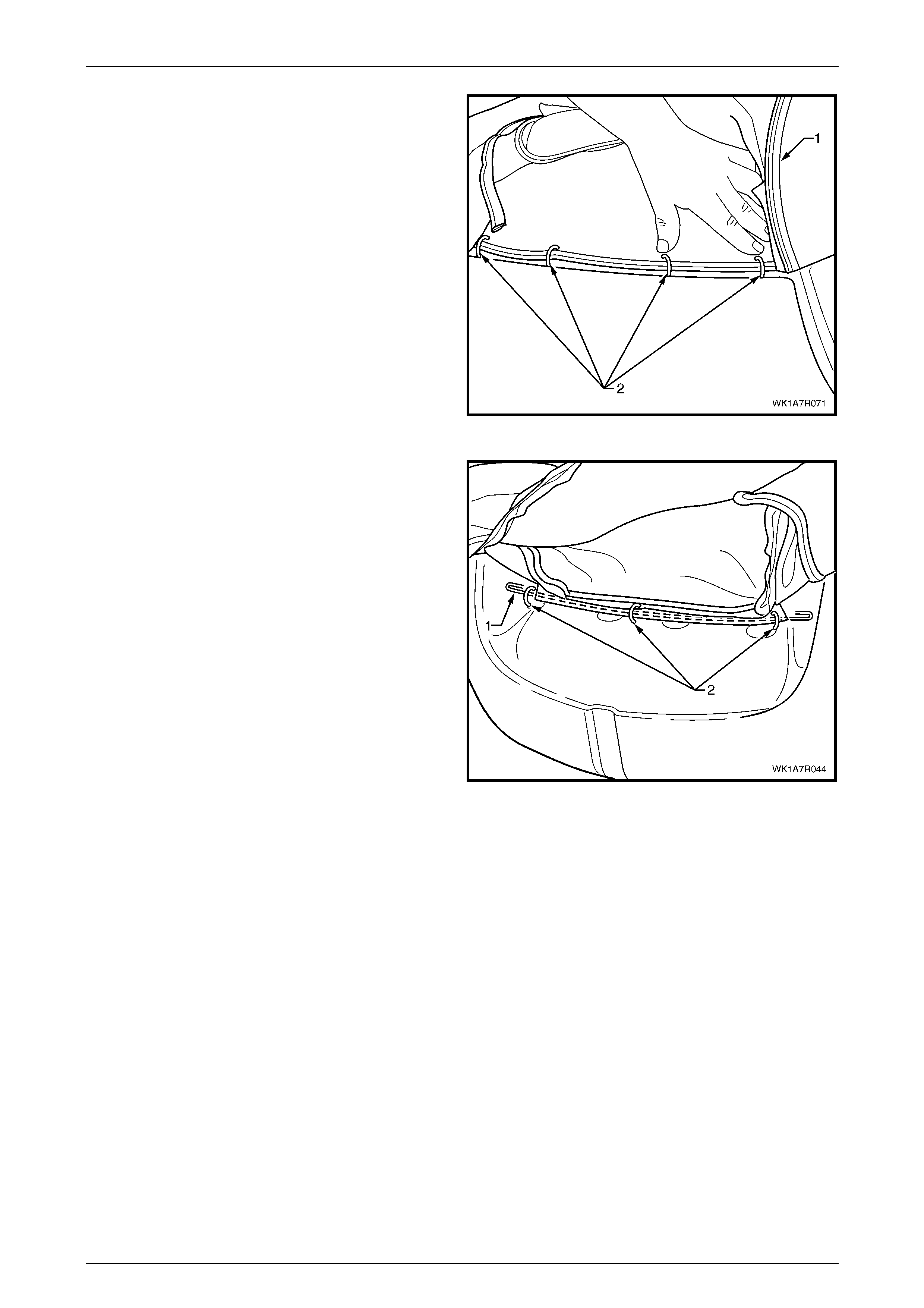
Seat Assemblies Page 1A7–386
Page 1A7–386
6 Continue to fit the cover (1) to the upper horiz ont al
groove and attach with four hog rings (2).
Figure 1A7 – 341
7 Fold the cover into the head restraint area and
attached the retaining wire (1) for the head restraint
with three hog rings (2) to the frame.
Figure 1A7 – 342
8 Place the seat-back assem bly face down on a clean surface and usin g the following sequence of operation s,
continue attaching the rear seat-back cover (1) to the pad assembly (2) with hog rings (3), approximately 31 places
in the positions shown, refer Figure 1A7 – 329.
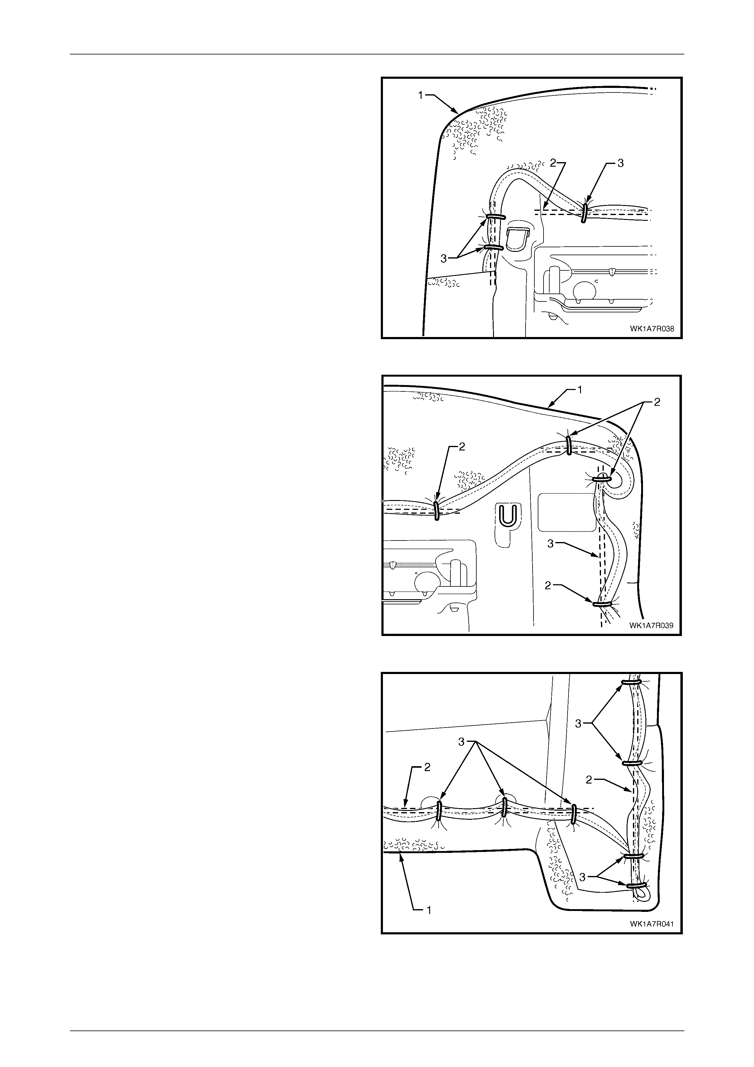
Seat Assemblies Page 1A7–387
Page 1A7–387
9 Starting at the upper inboard corner of the rear
seat-back, pull the cover (1) over the corner and
attach to the wire frame (2) with three hog rings (3).
Figure 1A7 – 343
10 While pulling the outboard side corner of the cover (1)
over the top and towards the centre, fix with four hog
rings (2) to the wire frame (3).
Figure 1A7 – 344
11 Continue at the outboard lower corner and attach the
cover (1) to the frame (2), by pulling the cover tight
and fixing with seven hog rings (3).
Figure 1A7 – 345
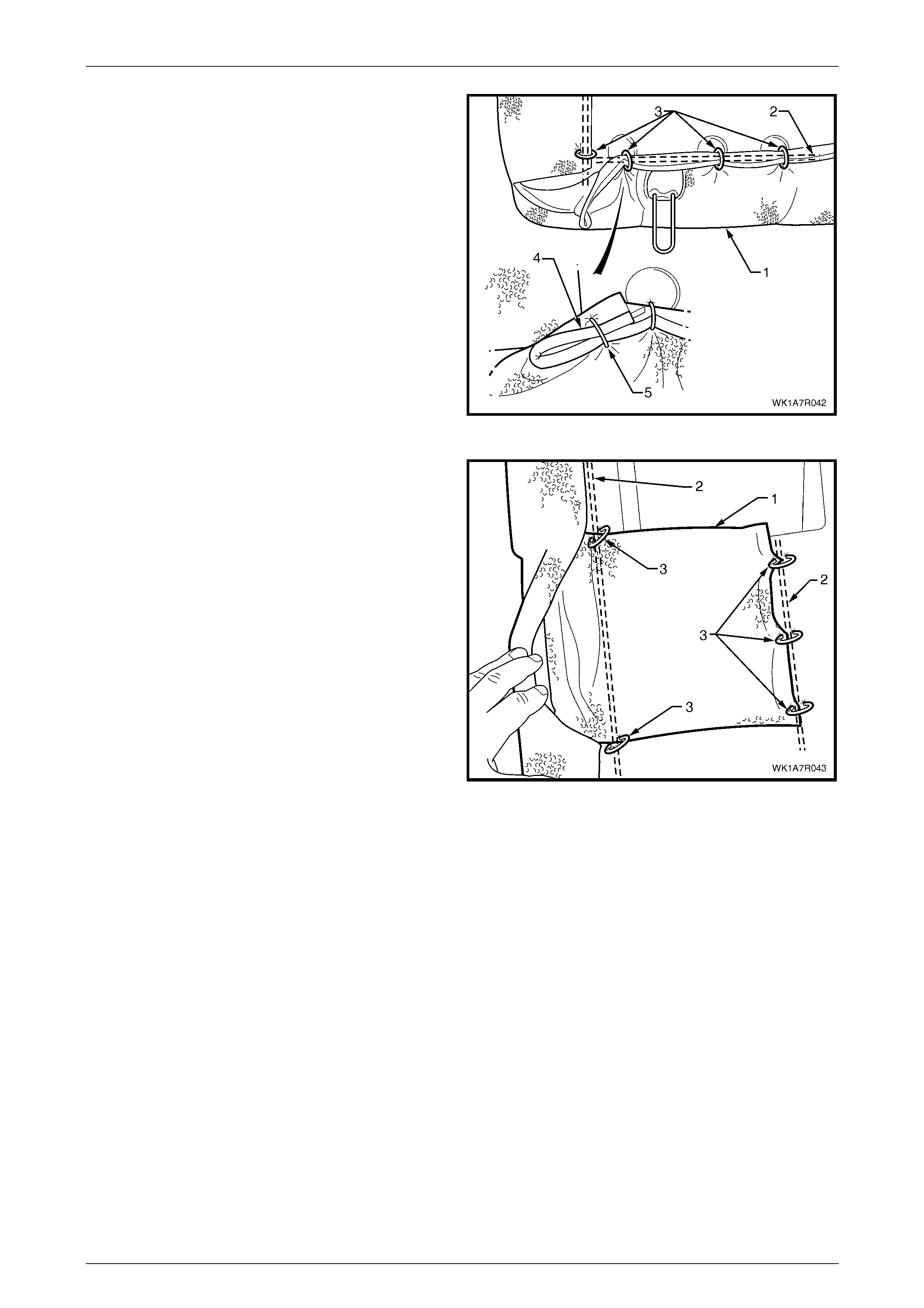
Seat Assemblies Page 1A7–388
Page 1A7–388
12 Continue at the inboard lower corner and attach the
cover (1) to the frame (2), by pulling the cover tight
and fixing with four hog rings (3).
13 Attach the seat-back cover lower piping overhang (4)
with one hog ring (5) back on to the lower piping.
Figure 1A7 – 346
14 Attach the first aid kit pouch (1) to the frame (2) with
five hog rings (3).
NOTE
Make sure the rear seat-back cover is fitted
neatly by hand into all corners and contours of
the seat pad and is free from any creases.
15 Continue along the inboard edge and attach the cover
to the frame, by pulling the cover tight and fixing with a
further three hog rings.
Figure 1A7 – 347
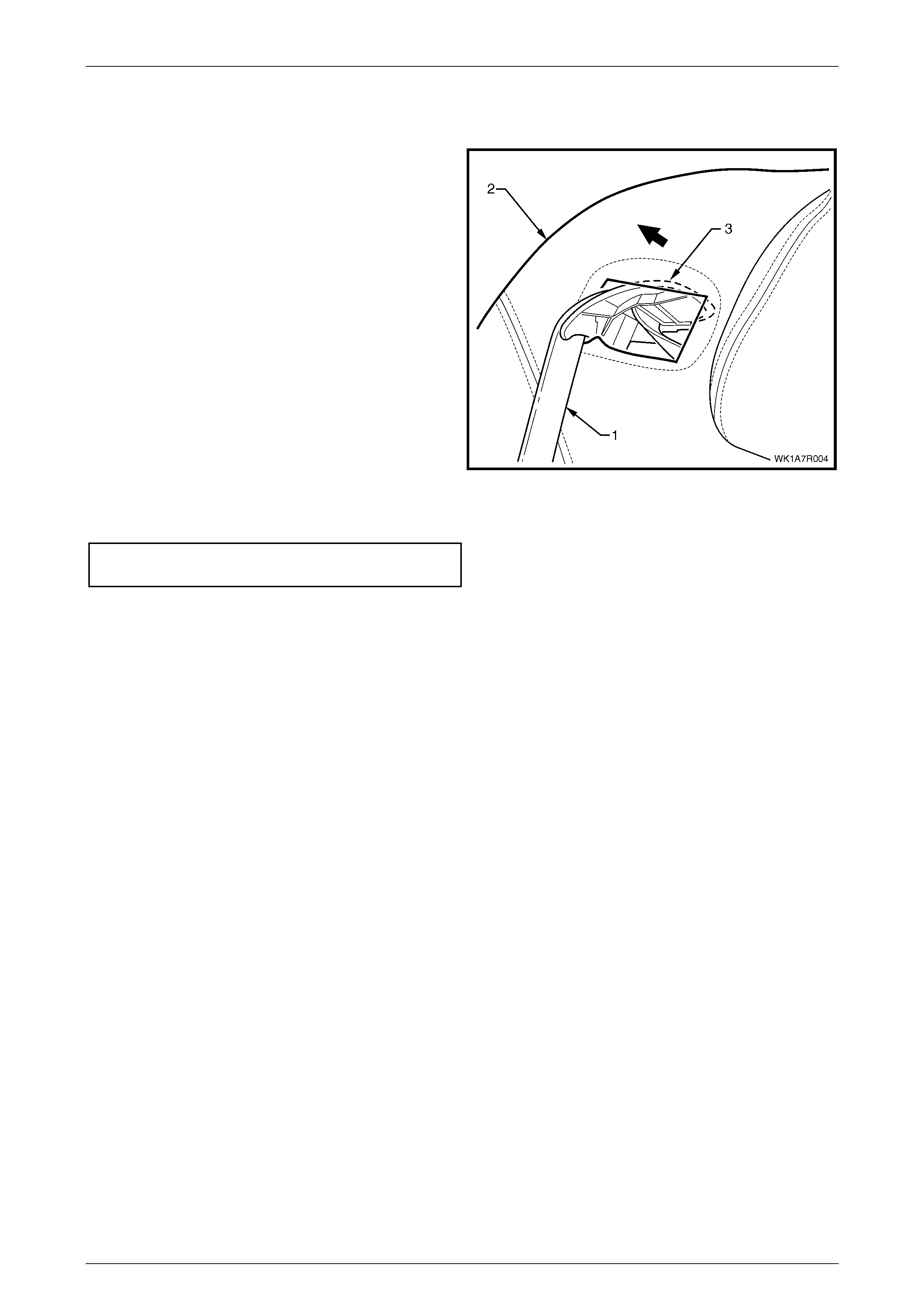
Seat Assemblies Page 1A7–389
Page 1A7–389
Reinstall
Reinstallation of the rear seat-back assembly is the reverse of the removal procedure, noting the following:
1 Feed the seatbelt (1) in through rear seat-back
assembly (2).
2 Position the seatbelt escutcheon (3) at an angle and
feed it through the rear seat-b ack as se mbly .
NOTE
Ensure the seatbelt is not twisted and its
operation is free from any int er feren ce
Figure 1A7 – 348
3 Tighten all retaining screws to the specified torque.
Rear seat-bac k assembly
attaching bolt torque specification.......... 25.0 – 35.0 Nm
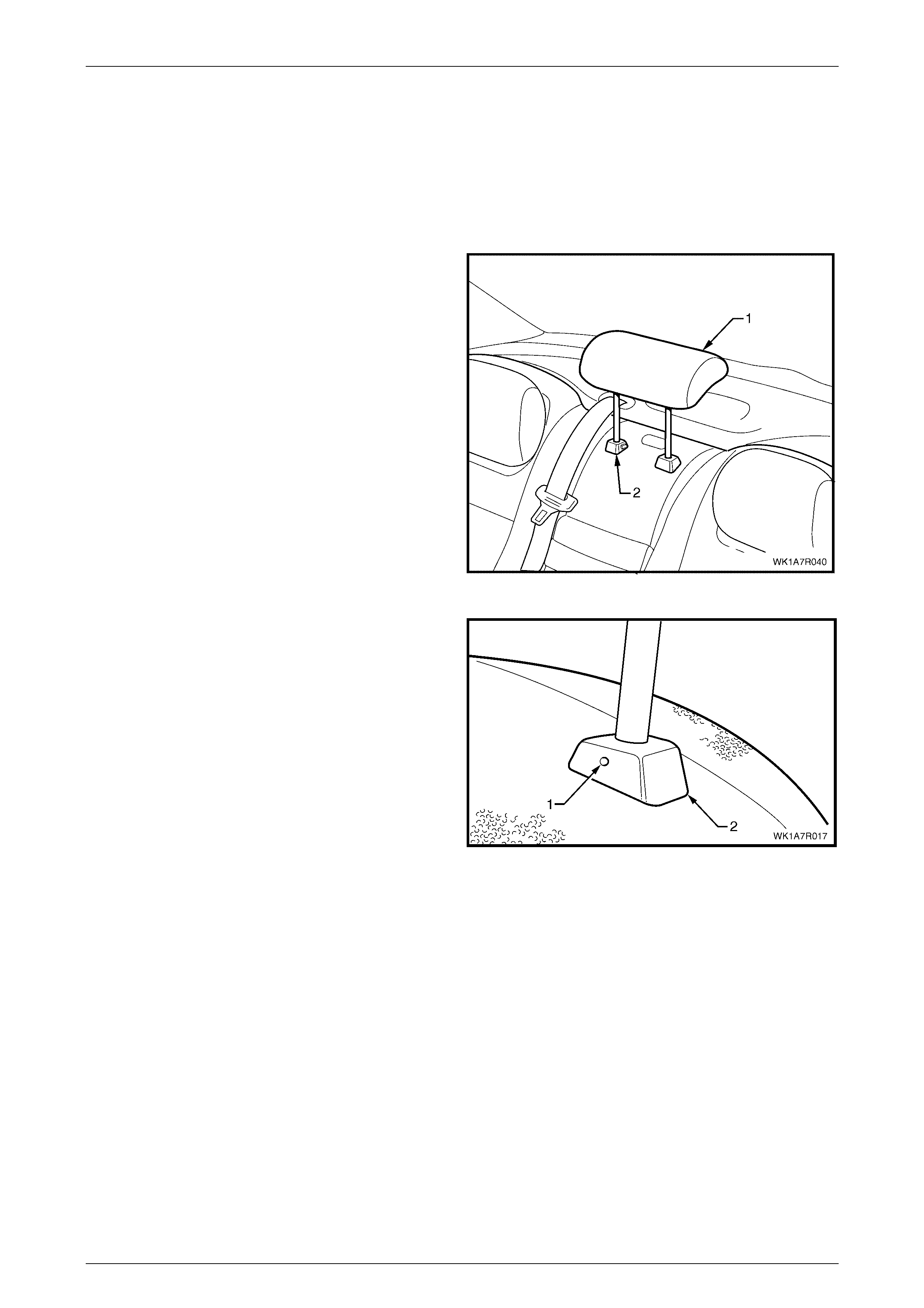
Seat Assemblies Page 1A7–390
Page 1A7–390
7.5 Rear Seat-back Centre Head Restraint
Assembly
LT Section No. – 14-350
Remove
1 Raise the rear seat-back centre head restraint (1) to
the first stop position.
2 Depress the head restraint sleeve height adjuster
lock (2) and raise the head restraint to the upper stop
position.
Figure 1A7 – 349
3 Manufacture a suitable size probe and insert into the
hole (1) in the left-hand head restraint sleeve (2).
4 Push the probe in slightly while applying slight upward
pressure on the head restraint and remove the head
restraint completely out of the sleeve.
Figure 1A7 – 350
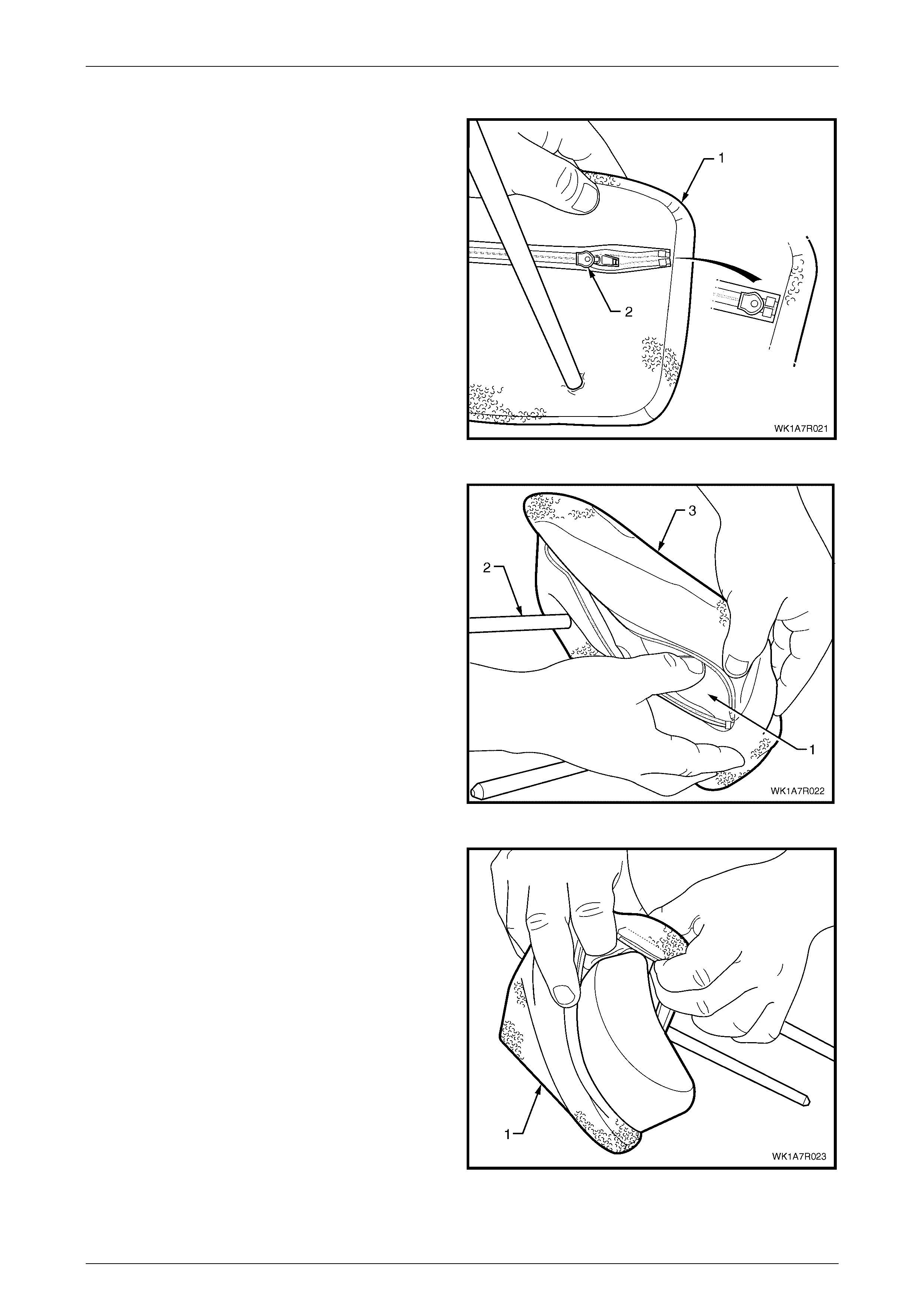
Seat Assemblies Page 1A7–391
Page 1A7–391
Disassemble
1 While holding the rear seat-back centre head restraint
(1) upside down, un-zip the cover taking note that the
tag for the zip (2) is located on the inside of the cover.
Figure 1A7 – 351
2 Beginning at one end, compress the foam (1) towards
the head restraint post (2) and begin to pull the cover
(3) over the pad.
3 Repeat this process for the other side.
Figure 1A7 – 352
4 Remove the cover (1) from the pad and slide off the
post.
Figure 1A7 – 353

Seat Assemblies Page 1A7–392
Page 1A7–392
Reassemble
Reassembly of the rear seat-back centre head restraint cover is the reverse of the removal process noting the following:
1 Position the head restraint cover over the post.
2 Starting at one end of the head restraint, insert the pad into the cover and working from one end to another, push
the pad into the cover until it is completely inserted.
3 Work the cover over the head restraint so that the cover is smooth and free from creases.
4 Close the zip ensuring the tag is located on the inside of the cover.
Reinstall
1 Position the head restraint in the head restraint sleeves and push the rear seat-back centre head restraint down
firmly.
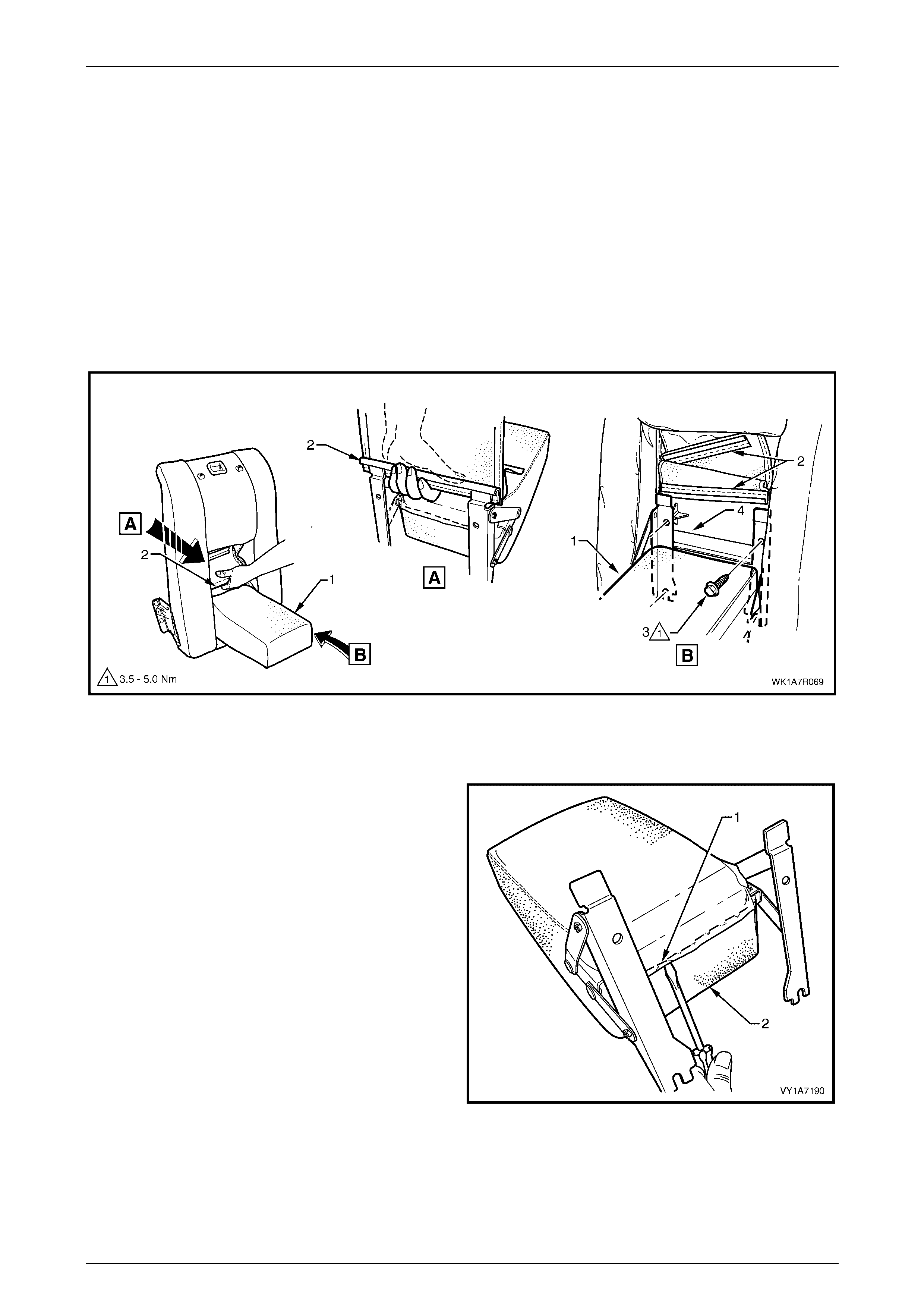
Seat Assemblies Page 1A7–393
Page 1A7–393
7.6 Rear Seat-back Centre Armrest
Assembly
LT Section No. – 14-325
Remove
1 Lower the armrest assembly (1) and disengage the trim flap J-strips (2) from the armrest hinge to gain access to
the retaining screws, refer to Figure 1A7 – 354.
2 Remove the retaining screw (3), in four places, from the rear seat-back centre tray (4), two from above the armrest
and two from below.
3 Remove the armrest assembly.
Figure 1A7 – 354
Disassemble Rear Seat Type 1 – 4
1 Remove the nine staples (1) securing the upper flap
armrest cover (2) to the armrest pad assembly.
Figure 1A7 – 355
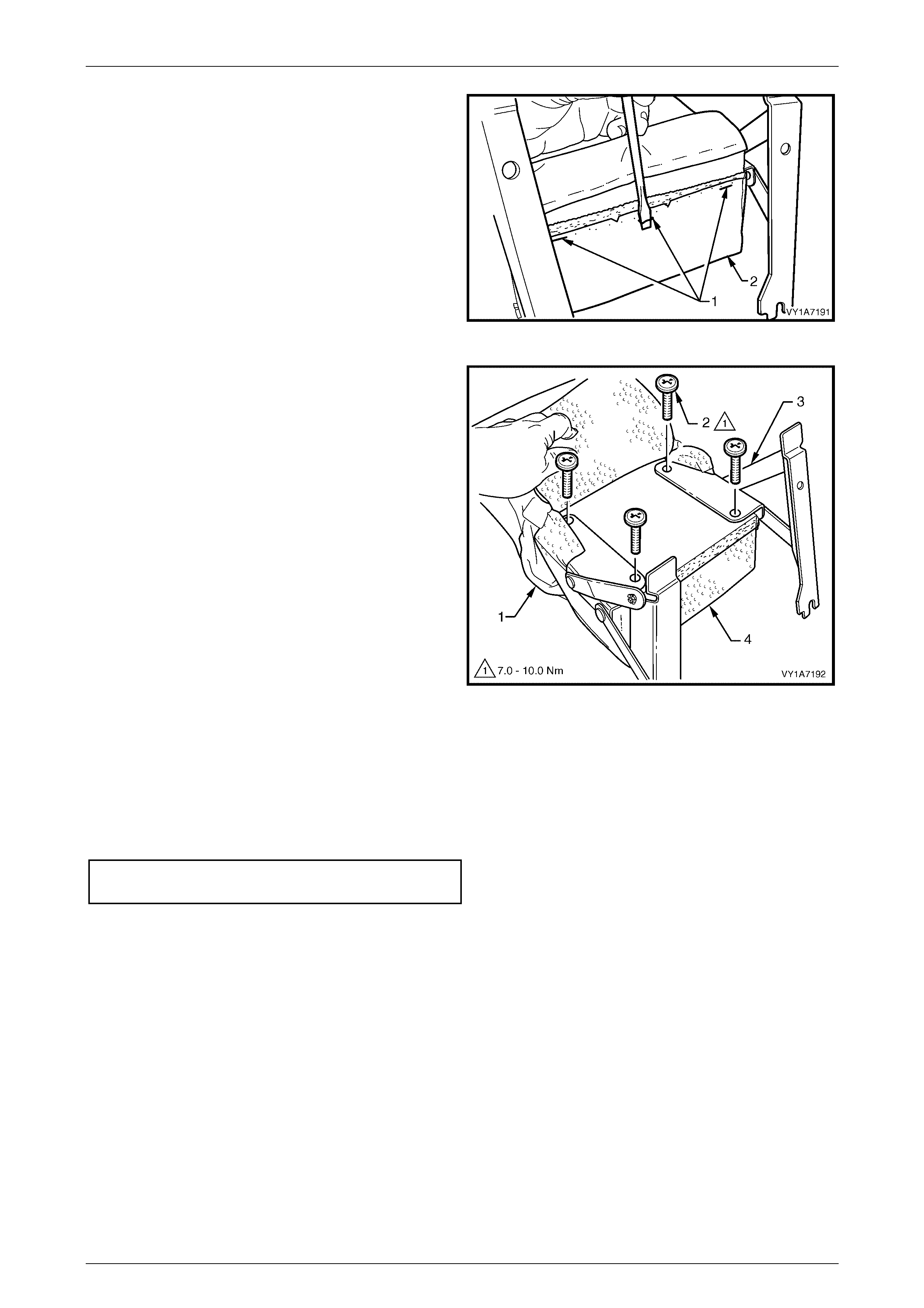
Seat Assemblies Page 1A7–394
Page 1A7–394
2 Remove the three staples (1) securing the lower flap
of the armrest cover (2) to the armrest pad assembly.
Figure 1A7 – 356
3 Pull the cover (1) along the armrest to allow access to
the hinge retaining screws (2).
4 Remove the four screws securing the armrest hinge
(3) to the armrest assembly (4) and remove the
hinges.
5 Remove the armrest cove r from the armrest pad
assembly.
Figure 1A7 – 357
Reassemble
Assembly of the rear seat-back centre armrest assembly is the reverse of the removal procedure, noting the following:
1 Ensure the armrest assembly hinge is installed before the cover is fitted.
2 Ensure all sc rews are tightened to the correct torque specification.
Armrest hinge attaching screw
torque specific atio n .................................. 7.0 – 10.0 Nm
3 The cover is to be smooth and without creases, before the staples are installed.
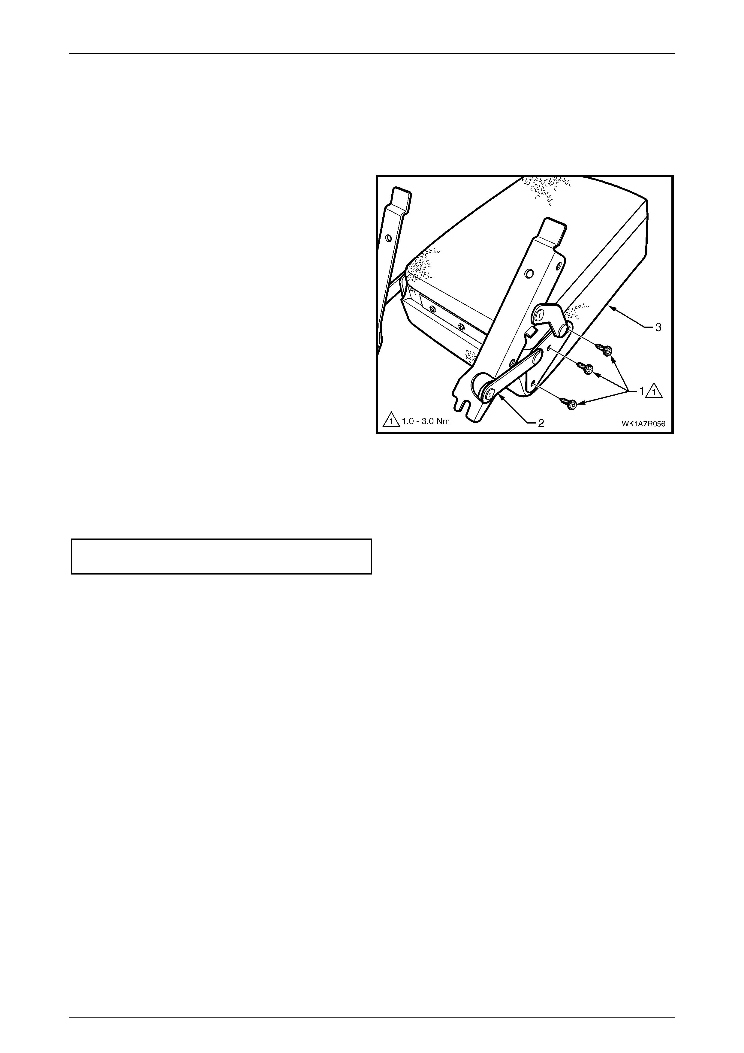
Seat Assemblies Page 1A7–395
Page 1A7–395
Disassemble Rear Seat Type 5 – 8
Rear Seat-back Centre Armrest Hinge
Remove
1 Remove the three screws (1) attaching the hinge (2) to
the rear seat-back centre armrest assembly (3).
Figure 1A7 – 358
Reinstall
Reinstallation of the rear seat-back centre armrest hinge is reverse of the removal procedure. Ensure all screws are
tightened to the specified torque.
Rear seat-back centre armrest hinge
attaching screw torque specific ation ........... 1.0 – 3.0 Nm
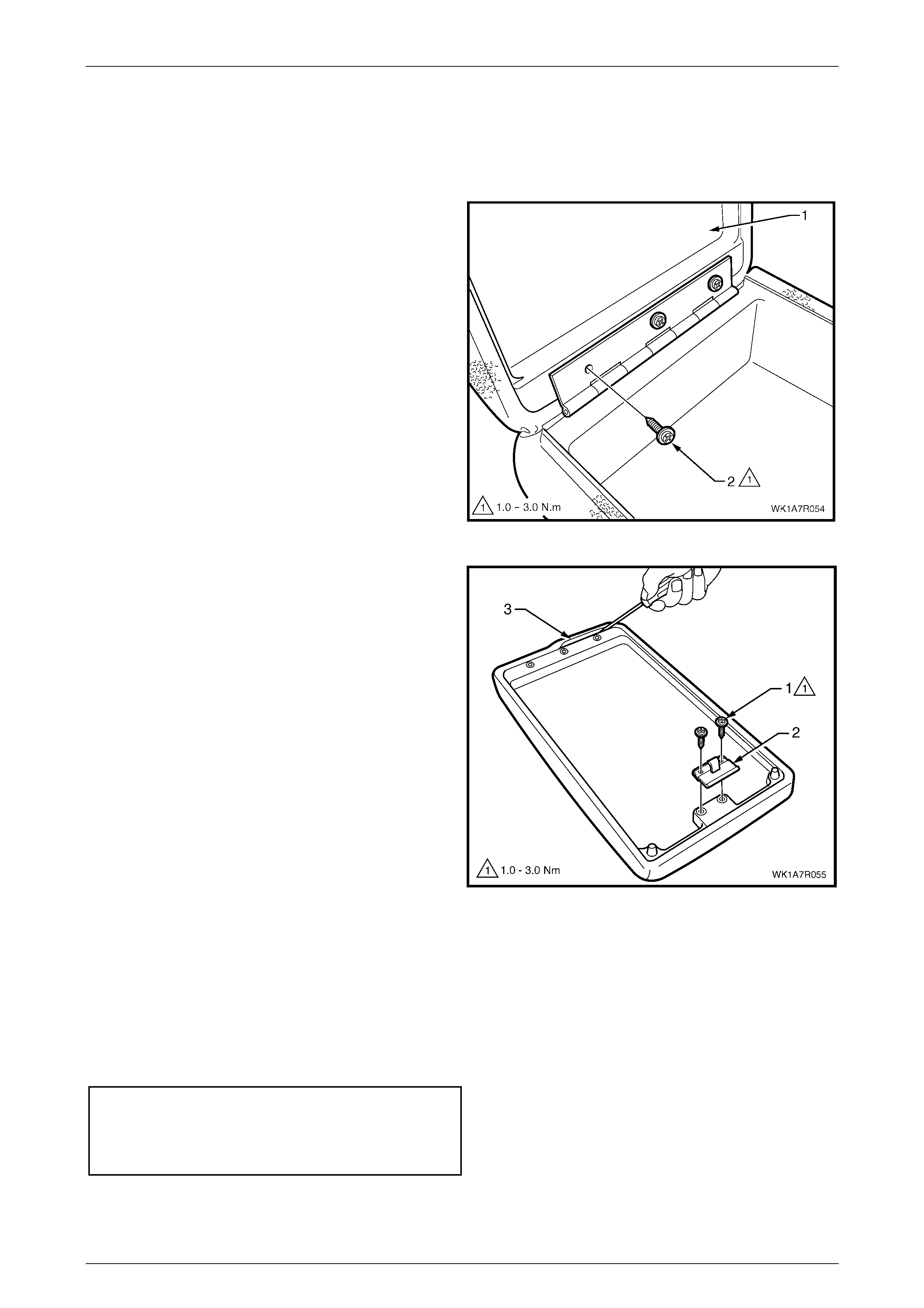
Seat Assemblies Page 1A7–396
Page 1A7–396
Rear Seat-back Centre Armrest Lid and Cover
If required, remove the armrest assembly, refe r to 7.6 Rear Seat-back Centre Armrest Assembly.
Remove
1 Open the rear seat-back centre armrest lid (1), remove
the three screws (2) and remove the lid.
Figure 1A7 – 359
2 Remove the two screws (1), attaching the armrest lid
latch (2).
3 Using a suitable size screwdriver, gently prise up the
retaining strip (3), three places.
4 Remove the cover from the rear seat-back centre
armrest lid.
Figure 1A7 – 360
Reinstall
Reinstallation of the rear seat-back centre armrest lid cover is the reverse of the removal procedure, noting the following:
1 Fit the cover by hand ensuring the cover is free from creases.
2 Ensure the retainer strips are located fully into the grooves.
3 Tighten all screws to the specified torque.
Rear seat-back centre armrest lid
attaching screw torque specific ation ........... 1.0 – 3.0 Nm
Rear seat-back centre armrest lid latch
attaching screw torque specific ation ........... 1.0 – 3.0 Nm
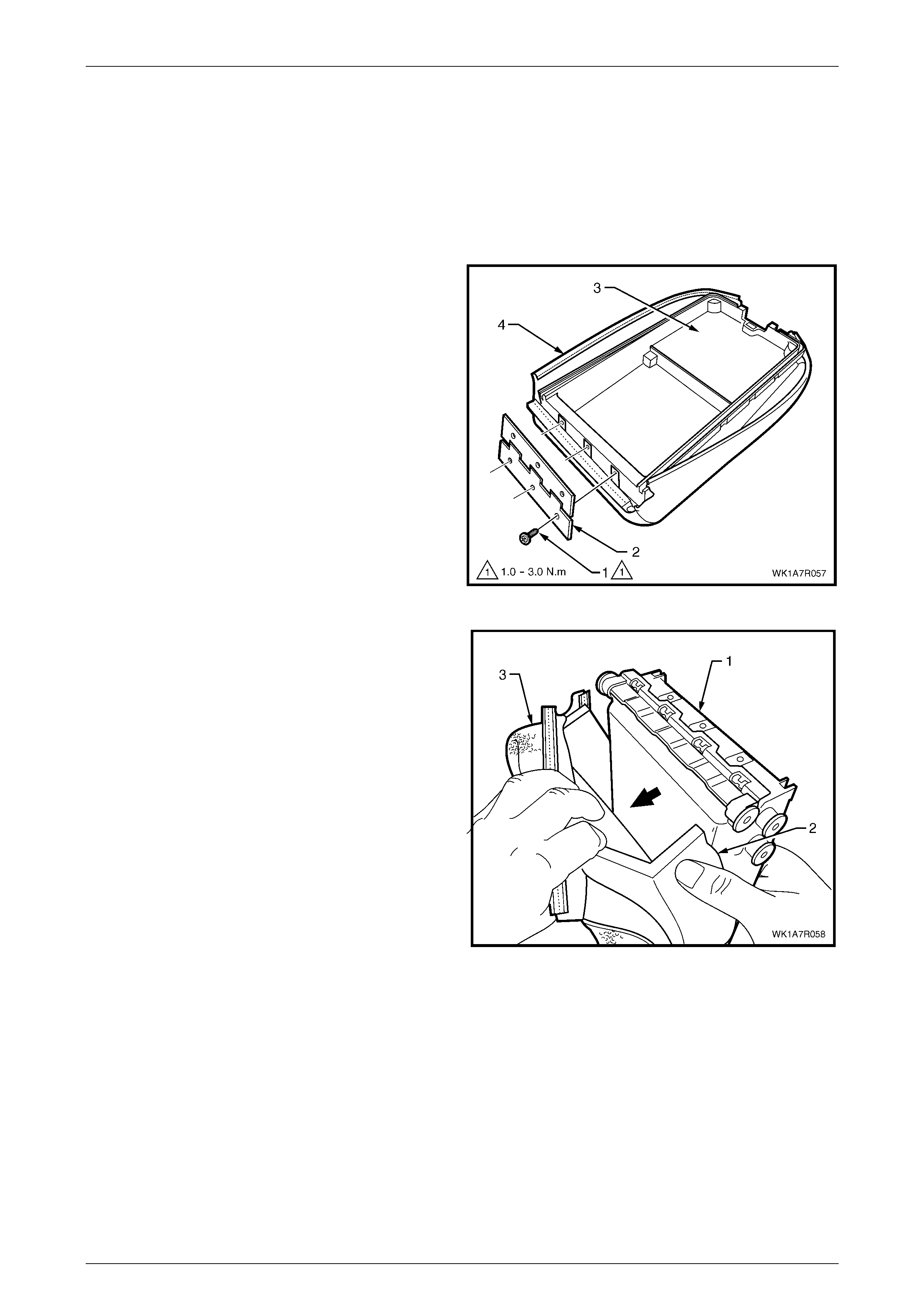
Seat Assemblies Page 1A7–397
Page 1A7–397
Rear Seat-back Centre Armrest Deposit Box, Cover and Cup Holder
To remove the rear seat-back centre armrest deposit box, cup holder or cover, the cover and cup holder need to be
removed from the rear seat-back centre armrest assembly as a combined unit. To assist the technician to disassemble
the seat-back centre armrest assembly without cross referencing to different sections, the deposit box, cover and cup
holder remove and reinstall procedures are all covered in the same procedure.
Remove
1 If required, remove the rear seat-back centre armrest lid, refer to Rear Seat-back Centre Armrest Lid and Cover.
2 Remove the sc rew (1), three places, attaching the rear
seat-back centre armrest lid hinge (2) to the deposit
box assembly (3).
3 Gently prise up the retaining strip (4), three places.
Figure 1A7 – 361
4 While holding the deposit box assembly (1) gently pull
the foam pad (2) and cover (3) away from the deposit
box.
Figure 1A7 – 362
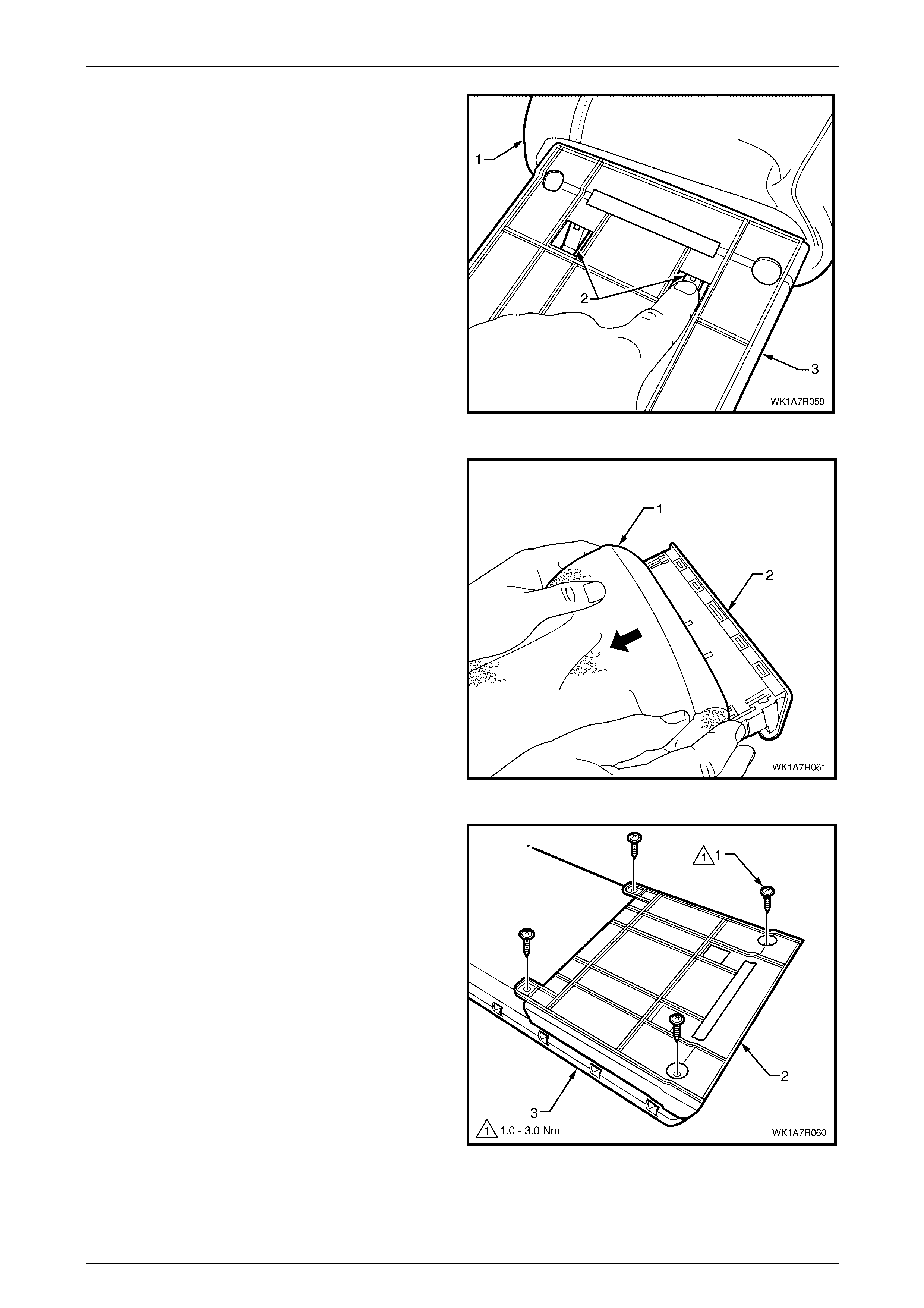
Seat Assemblies Page 1A7–398
Page 1A7–398
5 With the cover (1) folded back from the deposit box
assembly, depress the cup holder retaining tabs (2)
and remove the cup holder with the cover out of the
cup holder housing (3).
Figure 1A7 – 363
6 Remove the cover (1) from the cup holder (2) by
gently pulling the cover back over the cup holder.
Figure 1A7 – 364
7 Remove the four screws (1) attaching the cup holder
housing (2) to the deposit box (3).
Figure 1A7 – 365
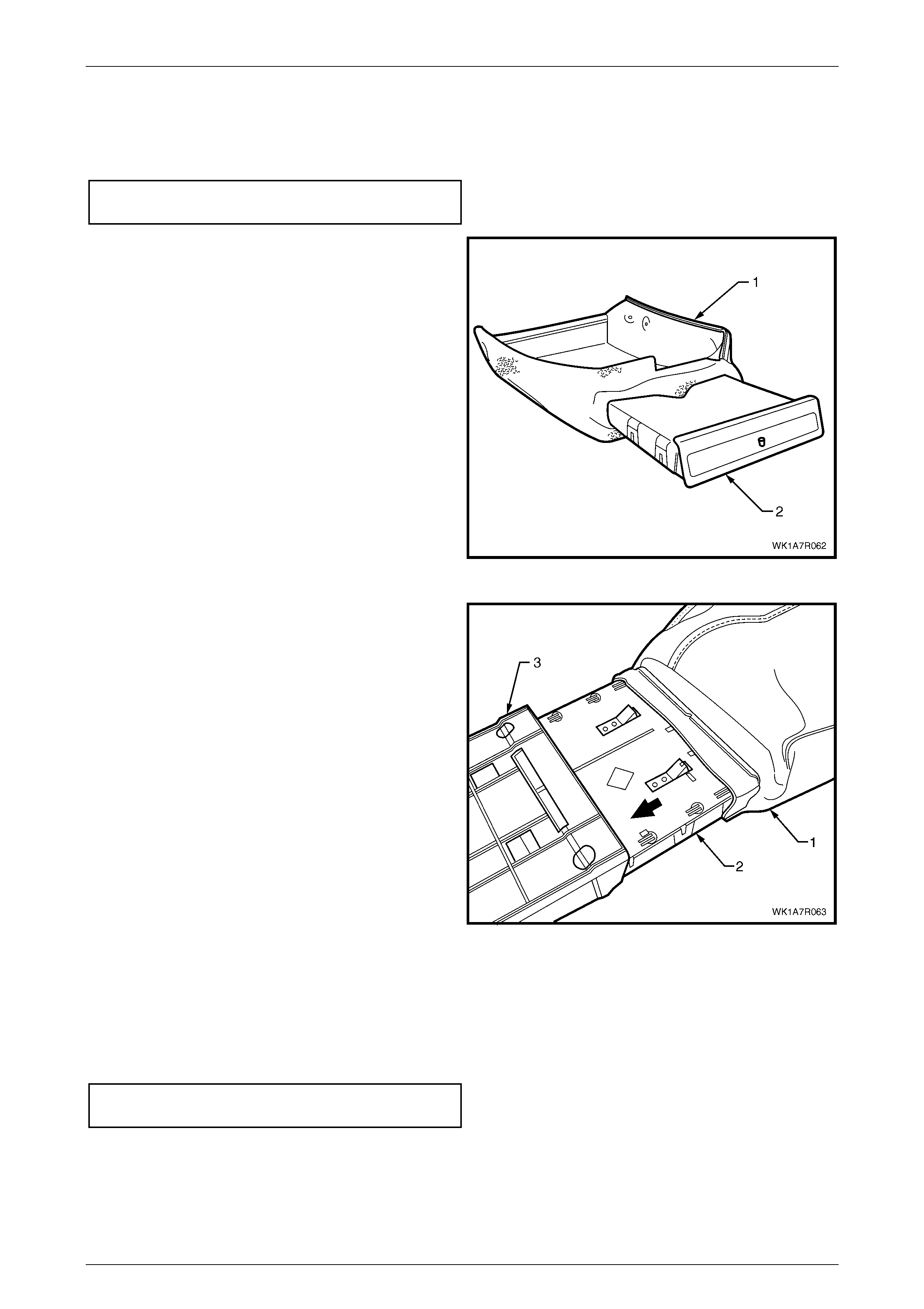
Seat Assemblies Page 1A7–399
Page 1A7–399
Reinstall
1 Reinstall the cup holder housing to the deposit box and tighten all screws to the specified torque, refer to
Figure 1A7 – 365.
Cup holder housing attaching
screw torque specification.......................... 1.0 – 3.0 Nm
2 Slide the cover (1) over the cup holder (2) ensuring the
cover fits neatly to the edge of the cup holder.
Figure 1A7 – 366
3 With the cover (1) folded back, slide the cup holder (2)
into the cup holder housing (3) attached to the deposit
box, ensuring the cover fits neatly into the cup holder
housing and the retaining clips lock in the cup holder
housing.
Figure 1A7 – 367
4 Reinstallation of the cover, pad and hinge is the reverse of the removal procedure noting the following:
a Ensure the cover is fitted neatly by hand and free from creases.
b All retainer strips are secured correctly.
c Tighten the rear seat-back centre armrest lid hinge screws to the specified torque.
Rear seat-back centre armrest lid hinge
attaching screw torque specification........... 1.0 – 3.0 Nm
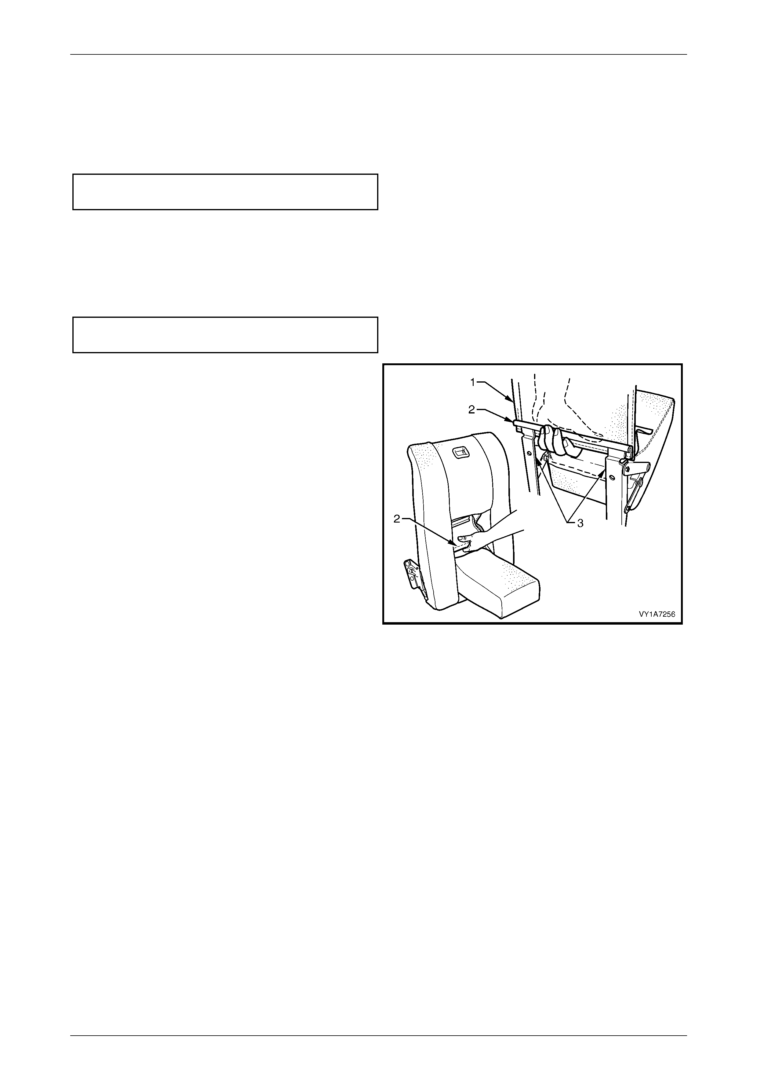
Seat Assemblies Page 1A7–400
Page 1A7–400
Reassemble
Reassembly of the rear seat-back centre armrest assembly is the reverse of the removal procedure, noting the following:
1 Ensure the armrest assembly hinge is installed before the cover is fitted and the screws are tightened to the
specified torque.
Armrest hinge attaching screw
torque specific atio n .................................. 7.0 – 10.0 Nm
Reinstall
Reinstallation of the rear seat-back centre armrest assembly is the reverse of the removal procedure, noting the
following:
1 Ensure all sc rews are tightened to the correct torque specification.
Armrest hinge assembly attaching screw
torque specific atio n .................................... 3.5 – 5.0 Nm
2 Refit the armrest trim flap (1) upper J-strip (2) to the
upper part of the hinge bracket (3).
Figure 1A7 – 368
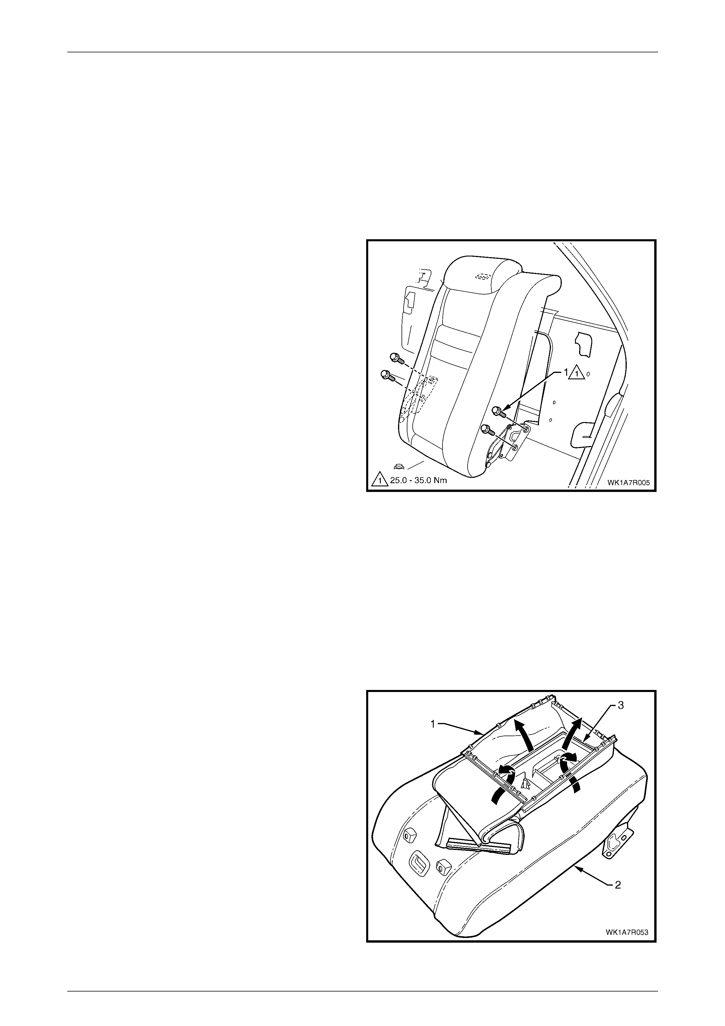
Seat Assemblies Page 1A7–401
Page 1A7–401
7.7 Rear Seat-back Centre Assembly
LT Section No. – 14-325
Remove
Although there are physical differences between the different types of centre rear seat-back assemblies, the removal and
reinstallation procedures are the same for all.
1 If required, remove the rear seat-back assembly, refer to 7.4 Rear Seat-back Assembly.
2 Remove the four bolts (1) attaching the rear seat-back
centre assembly to the rear compartment front panel.
3 Unlatch the rear seat-back assembly and remove from
the vehicle.
Figure 1A7 – 369
Disassemble
Pad Assembly, Cover and Head Restraint Sleeves
If required, remove the following:
1 Head restraint, refer to 7.5 Rear Seat-back Centre Head Restraint Assembly.
2 Rear seat-back centre armrest, refer to 7.6 Rear Seat-back Centre Armrest Assembly.
Remove
1 If fitted wi th an armrest, pull the four retaining strips (1)
in the centre of the seat-back centre assembly (2), up
and away from the insi de of the seat-back tray (3).
Figure 1A7 – 370
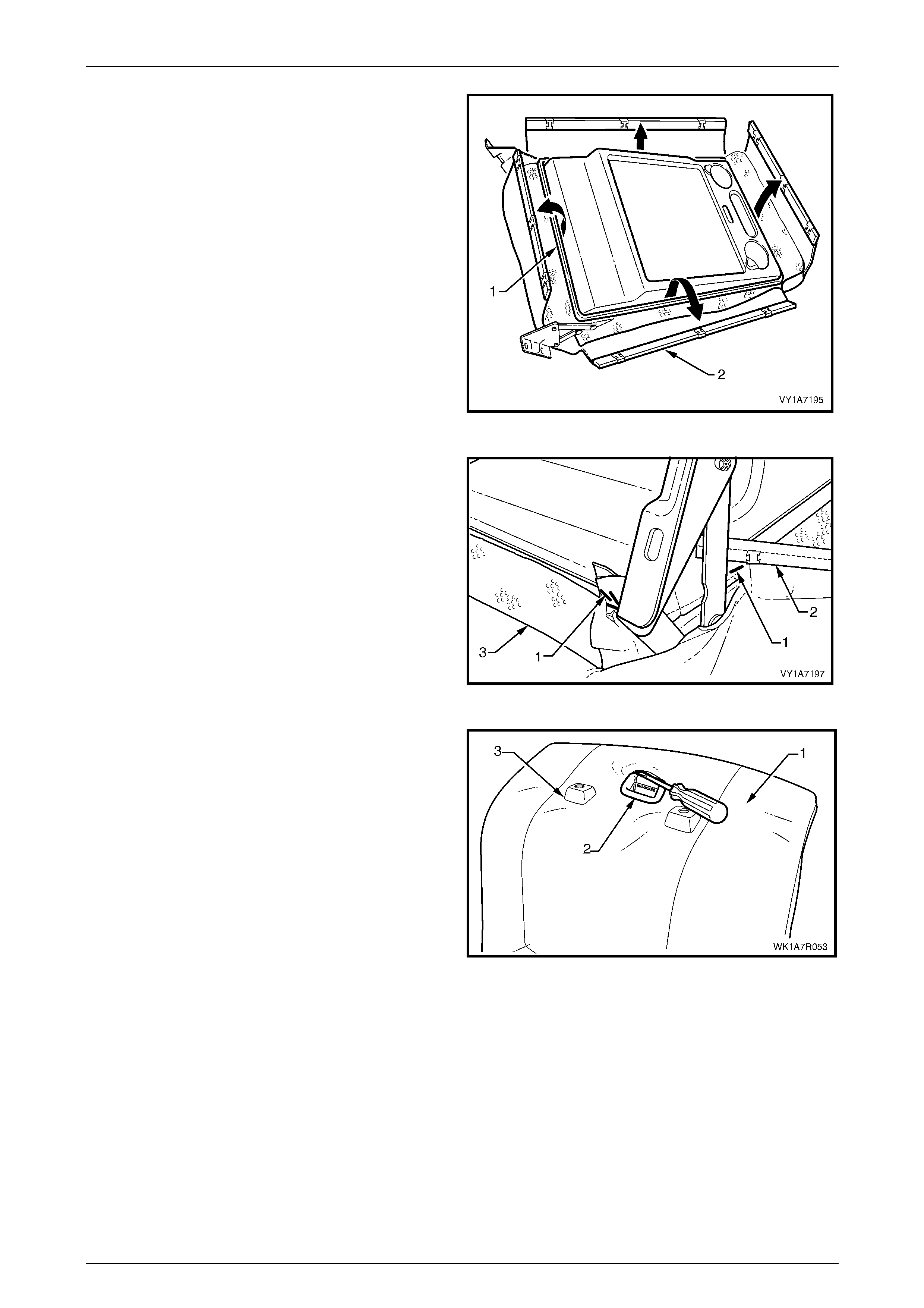
Seat Assemblies Page 1A7–402
Page 1A7–402
2 On the outer edge of the seat-back centre tray (1),
lever up the retaining strip (2), in four places.
Figure 1A7 – 371
3 Remove the four staples (1) each side, attaching the
cover (2) to the seat-back tray (3).
4 Peel the cover away from the seat-back tray.
Figure 1A7 – 372
5 Lever the seat cover material (1) over the release
button (2) and escutcheon assembly (3).
Figure 1A7 – 373
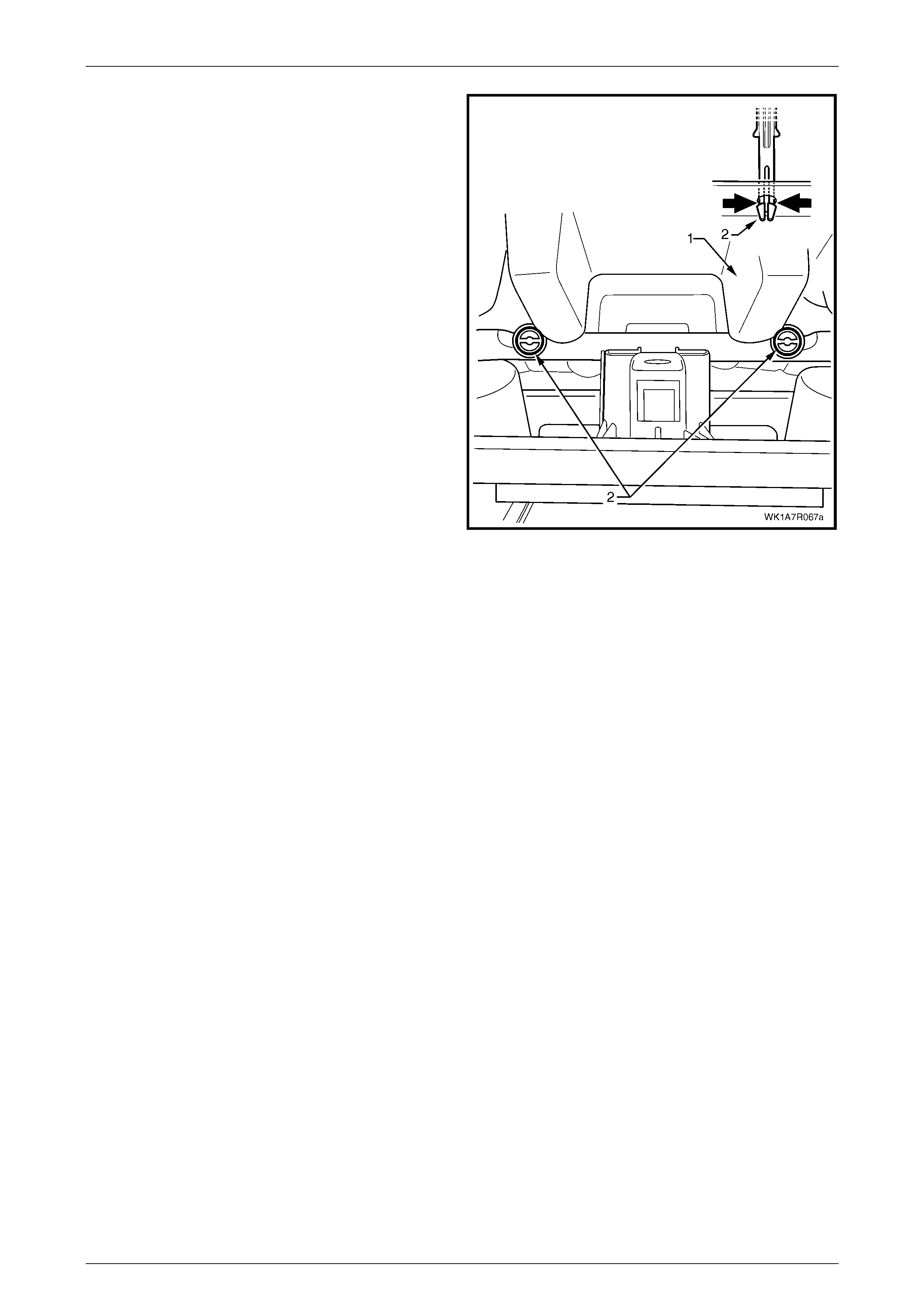
Seat Assemblies Page 1A7–403
Page 1A7–403
6 From the back of rear seat-back (1) (foam side), fold
the foam back and squeeze the head restraint sleeve
locating prongs (2) together and remove the sleeve up
and out of the centre seat-back assembly.
7 Remove the cover and pad.
Figure 1A7 – 374
Reinstall
Reinstallation of the rear seat centre back cover and pad assembly is the reverse of the removal procedure, noting the
following:
1 The cover is to be smooth and without creases before the staples are installed.
2 Ensure all retaining strips are attached properly.
3 When installing the head restraint sleeve, align the locating ribs with the key-way in the seat-back frame.
NOTE
Ensure the sleeve with the height adjuster lock is
installed on the side that corresponds to the
notches in the head restraint shaft.
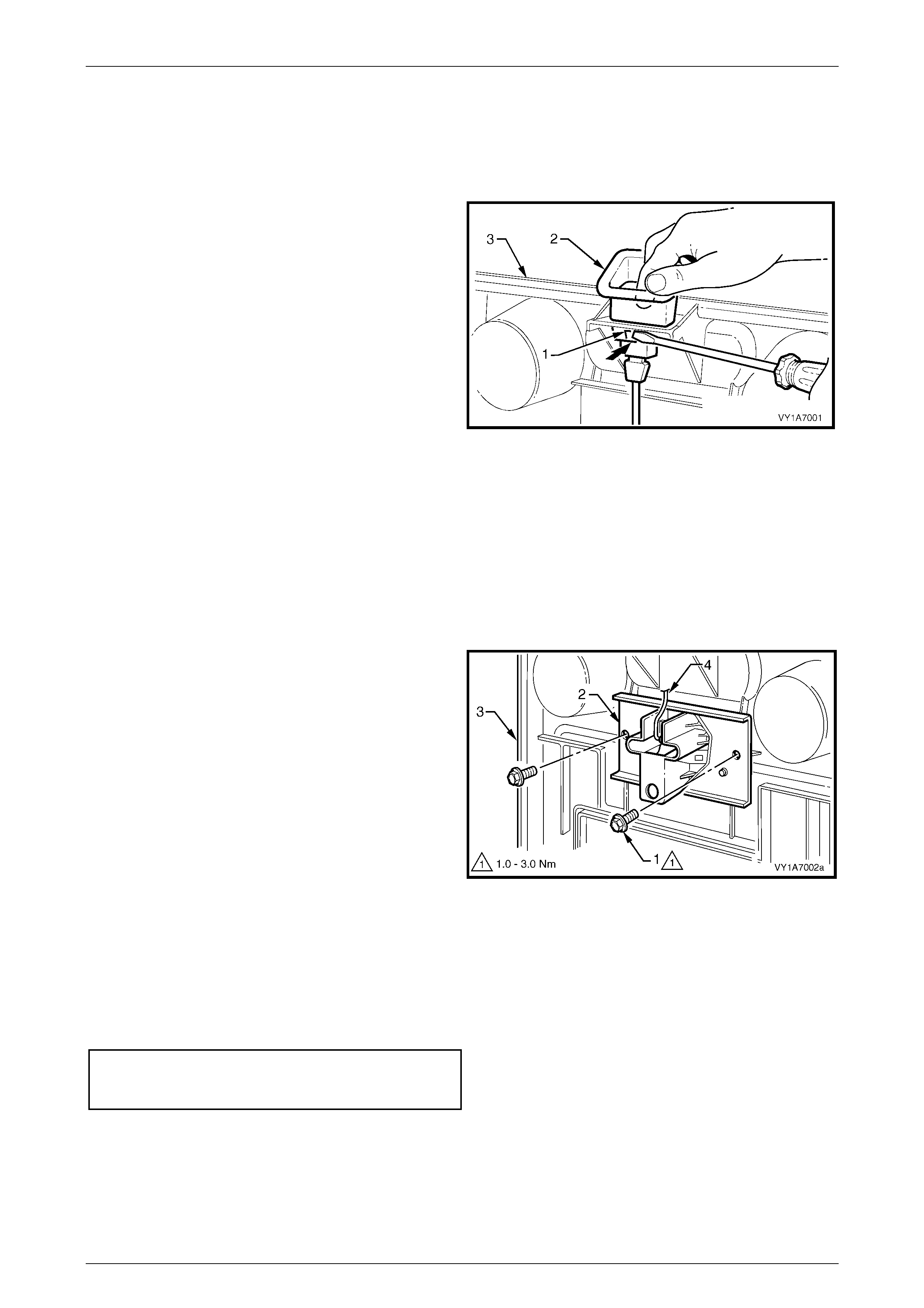
Seat Assemblies Page 1A7–404
Page 1A7–404
Rear Seat-b ack Cent re Re leas e Butto n
Remove
If required, remo ve the rear seat-back cover, refer to Pad Assembly, Cover and Head Restraint Sleeves.
1 Using a screwdriver, depress the two tangs (1) on the
front and rear of the release button (2).
2 Pull the release button from the rear seat-back
centre (3).
Figure 1A7 – 375
Reinstall
Push the release button into the rear seat-back centre assembly, until the button clicks home.
Rear Seat-back Centre Lock Actuator
Remove
If required, remo ve the rear seat-back cover, refer to Pad Assembly, Cover and Head Restraint Sleeves.
1 Remove the two screws (1) securing the lock
actuator (2) to the back tray (3) and remove lock
actuator.
2 Disengage the release button rod (4) from the lock
actuator.
Figure 1A7 – 376
Reinstall
Reinstallation of the rear seat-back centre lock actuator is the reverse of the removal procedure noting the following:
1 Ensure the button assembly and lock actuator rod are correctly engaged.
2 Ensure all sc rews are tightened to the correct torque specification.
Rear seat-back centre lock
actuator attaching screw
torque specific atio n .................................... 1.0 – 3.0 Nm
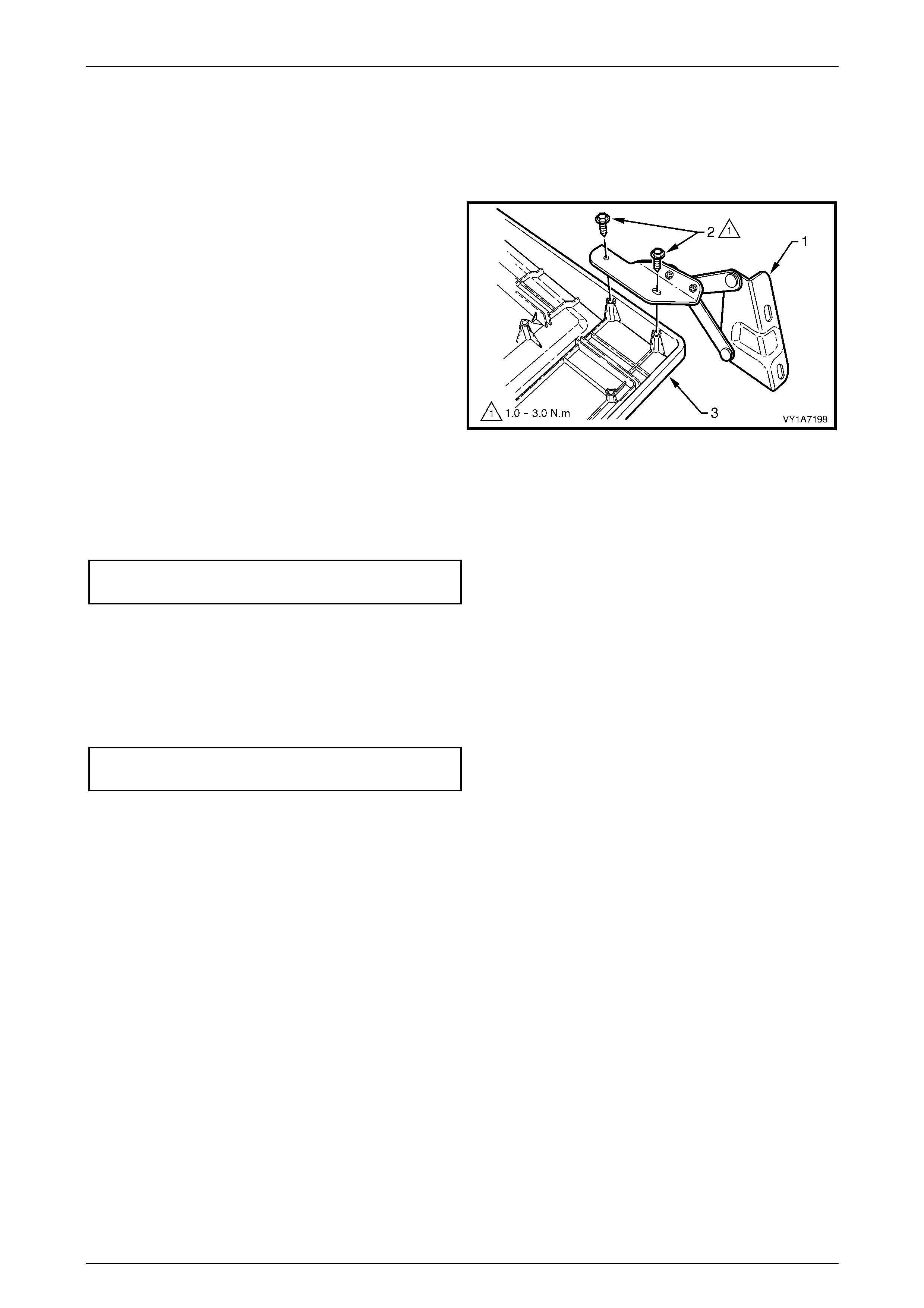
Seat Assemblies Page 1A7–405
Page 1A7–405
Rear Seat-b ack Cen tre Hi n ge
Remove
If required, remo ve the rear seat-back cover, refer to Pad Assembly, Cover and Head Restraint Sleeves.
1 Remove the two screws (2) securing the hinge (1) to
the rear seat-back centre tray assembly (3) and
remove the hinge.
2 If required, repeat for the opposite hinge.
Figure 1A7 – 377
Reinstall
Reinstallation of the rear seat-back centre hinge is the reverse of the removal procedure ensuring that all screws are
tightened to the specified torque.
Rear seat-back centre hinge
attaching screw torque specific ation ........... 1.0 – 3.0 Nm
Reinstall
Reinstallation of the rear seat-back assembly is the reverse of the removal procedure noting the following:
1 Ensure that the rear seat-back assembly is positioned centrally and there is no binding of the latch assembly.
2 Tighten all bolts to the specified torque.
Rear seat-back centre assembly
attaching bolt torque specification.......... 25.0 – 35.0 Nm
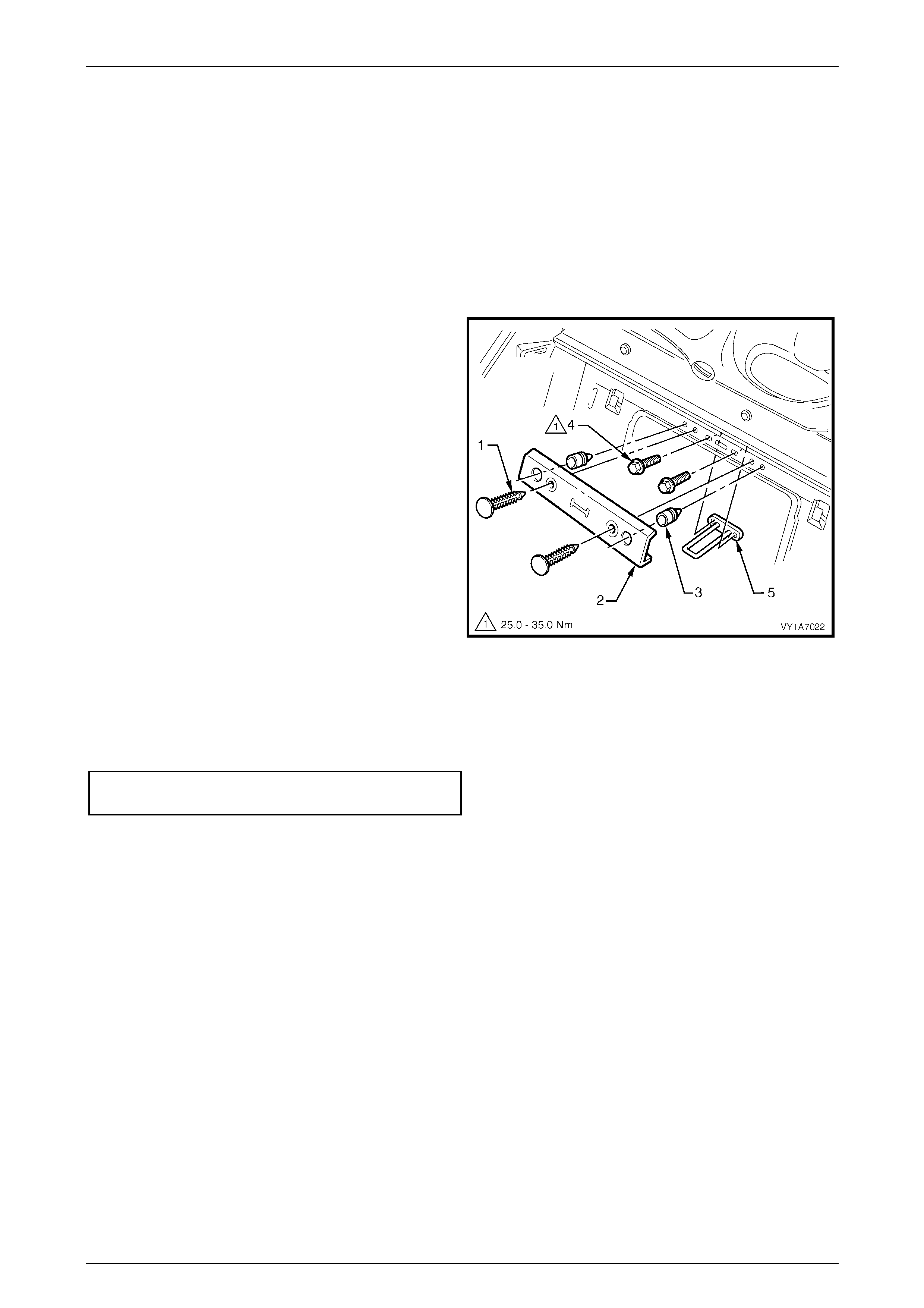
Seat Assemblies Page 1A7–406
Page 1A7–406
7.8 Rear Seat-back Centre Lock Striker
LT Section No. – 14-350
Remove
1 If required, remove the following:
a Remove the rear seat cushion assembly, refer to 7.2 Rear Seat Cushion Assembly.
b Remove the rear seat-back assembly, refer to 7.4 Rear Seat-back Assembly.
2 Prise the two retaining clips (1) securing the rear
seat-back cover (2) to the rear compartment front
panel and remove the cover.
3 If required, remove the two bump stops (3) from the
rear compartment front panel.
4 Remove the two screws (4) securing the striker (5) to
the rear panel and remove the striker.
Figure 1A7 – 378
Reinstall
Reinstallation of the rear seat lock striker is the reverse of the removal procedure ensuring that the retaining screws are
tightened to the correct torque specification.
Rear seat-back centre lock striker
attaching screw torque specific ation ....... 25.0 – 35.0 Nm

Seat Assemblies Page 1A7–407
Page 1A7–407
8 Torque Wrench Specifications
8.1 Front Seat
Level 1 and 3
Front Seat Assembly Attaching Screw.......................................35.0 – 50.0 Nm
Front Seat Adjustment Switch Attaching Screw.............................1.0 – 3.0 Nm
Front Seat Outer Side Cover Attaching Screw...............................1.0 – 3.0 Nm
Front Seat Inner Side Cover Attaching Screw...............................1.0 – 3.0 Nm
Front Seat-back Map Pocket Attaching Screw...............................1.0 – 3.0 Nm
Lumbar Support Adjuster Attaching Screw....................................1.0 – 3.0 Nm
Side Impact Airbag Assembly Attaching Nut..................................5.0 – 6.0 Nm
Front Seat Dummy Block Insert Assembly Attaching Nut..............5.0 – 6.0 Nm
Front Seat-back Frame Attaching Screw...................................30.0 – 45.0 Nm
Track and Height Adjust Assembly Attaching Nut......................24.0 – 32.0 Nm
Level 2, 4 and 5
Front Seat Assembly Attaching Screw.......................................35.0 – 50.0 Nm
Front Seat Outer Front Cover Attaching Sc rew .............................1.0 – 3.0 Nm
Front Seat Adjustment Switch Attaching Screw.............................1.0 – 3.0 Nm
Memory Position Switch Cover Attaching Screw...........................1.0 – 3.0 Nm
Front Seat Outer Side Cover Attaching Screw...............................1.0 – 3.0 Nm
Front Seat Inner Side Cover Attaching Screw...............................1.0 – 3.0 Nm
Front Seat-back Map Pocket Attaching Screw...............................1.0 – 3.0 Nm
Rear Seat Entertainment Screen Pivot Hinge Attaching Screw.....1.0 – 3.0 Nm
Rear Seat Entertainment Screen Attaching Sc rew........................ 1.0 – 3.0 Nm
Rear Seat Entertainment Circuit Board Attaching Screw...............1.0 – 3.0 Nm
Rear Seat Entertainment Head Rest Escutcheon Attaching
Screw.............................................................................................1.0 – 3.0 Nm
Lumbar Support Knob Attaching Screw......................................... 2.0 – 5.0 Nm
Side Impact Airbag Assembly Attaching Nut..................................5.0 – 6.0 Nm
Front Seat Dummy Block Insert Assembly Attaching Nut..............5.0 – 6.0 Nm
Active Head Restraint Frame Assembly Attaching Screw..............3.0 – 5.0 Nm
Front Seat-back Frame Assembly Attaching Screw...................30.0 – 45.0 Nm
Seat Memory Module Attaching Screw..........................................1.0 – 3.0 Nm
Track and Height Adjust Assembly Attaching Nut......................24.0 – 32.0 Nm

Seat Assemblies Page 1A7–408
Page 1A7–408
8.2 Rear Seat
Rear Seat-back Assembly Attaching Bolt..................................25.0 – 35.0 Nm
Rear Seat-back Centre Armrest Hinge Attaching Screw................1.0 – 3.0 Nm
Rear Seat-back Centre Armrest Lid Attaching Screw....................1.0 – 3.0 Nm
Rear Seat-back Centre Armrest Lid Latch Attaching Screw..........1.0 – 3.0 Nm
Cup Holder Housing Attaching Screw............................................1.0 – 3.0 Nm
Rear Seat-back Centre Armrest Lid Hinge Attaching Screw..........1.0 – 3.0 Nm
Armrest Hinge Attaching Screw...................................................7.0 – 10.0 Nm
Armrest Hinge Assembly Attaching Screw.....................................3.5 – 5.0 Nm
Rear Seat-back Centre Lock Actuator Attaching Screw.................1.0 – 3.0 Nm
Rear Seat-back Centre Hinge Attaching Screw.............................1.0 – 3.0 Nm
Rear Seat-back Centre Assembly Attaching Bolt.......................25.0 – 35.0 Nm
Rear Seat-back Centre Lock Striker Attaching Screw................25.0 – 35.0 Nm