
Seat Assemblies Page 1A7A–1
Page 1A7A–1
Section 1A7A Seat Assemblies
(Build No L253068 Onwards)
ATTENTION
Before performing any Service Operation or other procedure described in this Section, refer to Section 00
Warnings, Cautions and Notes for correct workshop practices with regard to safety and/or property damage.
1 General Information .............................................................................................................................14
1.1 Front Seat General Description.......................................................................................................................... 14
Seat Covers.......................................................................................................................................................... 15
Electric Seat Operation ....................................................................................................................................... 15
Raise/Lower Movement.................................................................................................................................... 15
Fore/Aft Movement........................................................................................................................................... 15
Recline Movement............................................................................................................................................ 16
Four-way and Six-way Movement Control........................................................................................................ 16
Eight-way Movement Control ........................................................................................................................... 16
Memory Seat Position System ......................................................................................................................... 17
Priority Keys (Level 5 Vehicles Only) ............................................................................................................... 17
Memory Buttons............................................................................................................................................... 18
Using the Exterior Mirrors................................................................................................................................. 18
Active Head Restraints........................................................................................................................................ 19
1.2 Rear Seat General Description ........................................................................................................................... 20
Seat Covers.......................................................................................................................................................... 20
Surebond.......................................................................................................................................................... 20
Hook and loop.................................................................................................................................................. 20
Conventional pull-down.................................................................................................................................... 20
2 Diagnostics – Front Seat, Level 1.......................................................................................................21
2.1 Prerequisites........................................................................................................................................................ 21
Safety Requirements ........................................................................................................................................... 21
Equipment ............................................................................................................................................................ 21
Testing Procedures ............................................................................................................................................. 21
2.2 Mechanical Diagnosis ......................................................................................................................................... 22
Lumbar Support Inoperative............................................................................................................................... 22
Introduction ...................................................................................................................................................... 22
Test Description ............................................................................................................................................... 22
Diagnostic Table............................................................................................................................................... 22
Seat-back Recline Forward and/or Aft Function is Inoperative....................................................................... 23
Introduction ...................................................................................................................................................... 23
Test Description ............................................................................................................................................... 23
Diagnostic Table............................................................................................................................................... 23
Four-way Seat Fore/Aft Movement Function is Inoperative or is Not Smooth............................................... 23
Introduction ...................................................................................................................................................... 23
Test Description ............................................................................................................................................... 23
Diagnostic Table............................................................................................................................................... 23

Seat Assemblies Page 1A7A–2
Page 1A7A–2
2.3 Electrical Diagnosis – Four-way/Six-way Seat.................................................................................................. 24
Wiring Diagram – Four-way/Six-way Seat.......................................................................................................... 25
Connector Chart – Four-way/Six-way Seat........................................................................................................ 26
Neither Seat Adjustment Switch Functions Operate........................................................................................ 27
Introduction ...................................................................................................................................................... 27
Test Description ............................................................................................................................................... 27
Diagnostic Table Notes .................................................................................................................................... 27
Diagnostic Table............................................................................................................................................... 28
None of the Driver’s Seat Adjustment Switch Functions Operate...................................................................29
Introduction ...................................................................................................................................................... 29
Test Description ............................................................................................................................................... 29
Diagnostic Table Notes .................................................................................................................................... 29
Diagnostic Table............................................................................................................................................... 30
Front/Rear of the Driver's Seat Does Not Raise and/or Lower......................................................................... 31
Introduction ...................................................................................................................................................... 31
Test Description ............................................................................................................................................... 31
Diagnostic Table Notes .................................................................................................................................... 31
Diagnostic Table............................................................................................................................................... 32
Driver’s Seat Fore/Aft Movement Function is Inoperative or not Smooth...................................................... 33
Introduction ...................................................................................................................................................... 33
Test Description ............................................................................................................................................... 33
Diagnostic Table Notes .................................................................................................................................... 33
Diagnostic Table............................................................................................................................................... 34
None of the Passenger's Seat Adjustment Switch Functions Operate...........................................................35
Introduction ...................................................................................................................................................... 35
Test Description ............................................................................................................................................... 35
Diagnostic Table Notes .................................................................................................................................... 35
Diagnostic Table............................................................................................................................................... 36
Front/Rear of the Passenger's Seat Does Not Raise and/or Lower.................................................................37
Introduction ...................................................................................................................................................... 37
Test Description ............................................................................................................................................... 37
Diagnostic Table Notes .................................................................................................................................... 37
Diagnostic Table............................................................................................................................................... 38
2.4 Four-way Seat Adjustment Switch Test............................................................................................................. 39
Test ....................................................................................................................................................................... 39
2.5 Six-way Seat Adjustment Switch Test ............................................................................................................... 40
Test ....................................................................................................................................................................... 40
3 Diagnostics – Front Seat, Level 2, 3, 4 and 5 ....................................................................................41
3.1 Prerequisites........................................................................................................................................................ 41
Safety Requirements ........................................................................................................................................... 41
Equipment ............................................................................................................................................................ 41
Testing Procedures ............................................................................................................................................. 41
3.2 Mechanical Diagnosis ......................................................................................................................................... 42
Lumbar Support Inoperative............................................................................................................................... 42
Introduction ...................................................................................................................................................... 42
Test Description ............................................................................................................................................... 42
Diagnostic Table............................................................................................................................................... 42

Seat Assemblies Page 1A7A–3
Page 1A7A–3
3.3 Electrical Diagnosis – Eight-way Seat, Non-memory, RHD.............................................................................. 43
Wiring Diagram – Eight-way Seat, Non-memory, RHD..................................................................................... 44
Connector Chart – Eight-way Seat, Non-memory, RHD ................................................................................... 45
Neither Seat Adjustment Switch Functions Operate........................................................................................ 46
Introduction ...................................................................................................................................................... 46
Test Description ............................................................................................................................................... 46
Diagnostic Table Notes .................................................................................................................................... 46
Diagnostic Table............................................................................................................................................... 47
None of the Driver’s Seat Adjustment Switch Functions Operate...................................................................48
Introduction ...................................................................................................................................................... 48
Test Description ............................................................................................................................................... 48
Diagnostic Table Notes .................................................................................................................................... 48
Diagnostic Table............................................................................................................................................... 49
Front/Rear of the Driver’s Seat Does Not Raise and/or Lower......................................................................... 50
Introduction ...................................................................................................................................................... 50
Test Description ............................................................................................................................................... 50
Diagnostic Table Notes .................................................................................................................................... 50
Diagnostic Table............................................................................................................................................... 51
Driver’s Seat Fore/Aft Movement Function is Inoperative or Not Smooth...................................................... 52
Introduction ...................................................................................................................................................... 52
Test Description ............................................................................................................................................... 52
Diagnostic Table Notes .................................................................................................................................... 52
Diagnostic Table............................................................................................................................................... 53
Driver’s Seat-back Recline Forw ard and/or Aft Function is Inoperative......................................................... 54
Introduction ...................................................................................................................................................... 54
Test Description ............................................................................................................................................... 54
Diagnostic Table Notes .................................................................................................................................... 54
Diagnostic Table............................................................................................................................................... 55
None of the Passenger’s Seat Adjustment Switch Functions Operate........................................................... 56
Introduction ...................................................................................................................................................... 56
Test Description ............................................................................................................................................... 56
Diagnostic Table Notes .................................................................................................................................... 56
Diagnostic Table............................................................................................................................................... 57
Front/Rear of the Passenger’s Seat Does Not Raise and/or Lower................................................................. 58
Introduction ...................................................................................................................................................... 58
Test Description ............................................................................................................................................... 58
Diagnostic Table Notes .................................................................................................................................... 58
Diagnostic Table............................................................................................................................................... 59
Passenger’s Seat Fore/Aft Movement Function is Inoperative or Not Smooth.............................................. 60
Introduction ...................................................................................................................................................... 60
Test Description ............................................................................................................................................... 60
Diagnostic Table Notes .................................................................................................................................... 60
Diagnostic Table............................................................................................................................................... 61
Passenger’s Seat-back Recline Forward and/or Aft Function is Inoperative................................................. 62
Introduction ...................................................................................................................................................... 62
Test Description ............................................................................................................................................... 62
Diagnostic Table Notes .................................................................................................................................... 62
Diagnostic Table............................................................................................................................................... 63

Seat Assemblies Page 1A7A–4
Page 1A7A–4
3.4 Electrical Diagnosis – Eight-way Seat, Non-memory, LHD.............................................................................. 64
Wiring Diagram – Eight-way Seat, Non-memory, LHD...................................................................................... 65
Connector Chart – Eight-way Seat, Non-memory, LHD.................................................................................... 66
Neither Seat Adjustment Switch Functions Operate........................................................................................ 67
Introduction ...................................................................................................................................................... 67
Test Description ............................................................................................................................................... 67
Diagnostic Table Notes .................................................................................................................................... 67
Diagnostic Table............................................................................................................................................... 68
None of the Driver’s Seat Adjustment Switch Functions Operate...................................................................69
Introduction ...................................................................................................................................................... 69
Test Description ............................................................................................................................................... 69
Diagnostic Table Notes .................................................................................................................................... 69
Diagnostic Table............................................................................................................................................... 70
Front/Rear of the Driver’s Seat Does Not Raise and/or Lower......................................................................... 71
Introduction ...................................................................................................................................................... 71
Test Description ............................................................................................................................................... 71
Diagnostic Table Notes .................................................................................................................................... 71
Diagnostic Table............................................................................................................................................... 72
Driver’s Seat Fore/Aft Movement Function is Inoperative or Not Smooth...................................................... 73
Introduction ...................................................................................................................................................... 73
Test Description ............................................................................................................................................... 73
Diagnostic Table Notes .................................................................................................................................... 73
Diagnostic Table............................................................................................................................................... 74
Driver’s Seat-back Recline Forw ard and/or Aft Function is Inoperative......................................................... 75
Introduction ...................................................................................................................................................... 75
Test Description ............................................................................................................................................... 75
Diagnostic Table Notes .................................................................................................................................... 75
Diagnostic Table............................................................................................................................................... 76
None of the Passenger’s Seat Adjustment Switch Functions Operate........................................................... 77
Introduction ...................................................................................................................................................... 77
Test Description ............................................................................................................................................... 77
Diagnostic Table Notes .................................................................................................................................... 77
Diagnostic Table............................................................................................................................................... 78
Front/Rear of the Passenger’s Seat Does Not Raise and/or Lower................................................................. 79
Introduction ...................................................................................................................................................... 79
Test Description ............................................................................................................................................... 79
Diagnostic Table Notes .................................................................................................................................... 79
Diagnostic Table............................................................................................................................................... 80
Passenger’s Seat Fore/Aft Movement Function is Inoperative or Not Smooth.............................................. 81
Introduction ...................................................................................................................................................... 81
Test Description ............................................................................................................................................... 81
Diagnostic Table Notes .................................................................................................................................... 81
Diagnostic Table............................................................................................................................................... 82
Passenger’s Seat-back Recline Forward and/or Aft Function is Inoperative................................................. 83
Introduction ...................................................................................................................................................... 83
Test Description ............................................................................................................................................... 83
Diagnostic Table Notes .................................................................................................................................... 83
Diagnostic Table............................................................................................................................................... 84
3.5 Eight-way Seat Adjustment Switch Test............................................................................................................ 85
Test ....................................................................................................................................................................... 85

Seat Assemblies Page 1A7A–5
Page 1A7A–5
4 Diagnostics – Front Seat, Memory and Rear-view Mirror, Level 5..................................................86
4.1 Prerequisites........................................................................................................................................................ 86
Safety Requirements ........................................................................................................................................... 86
Equipment ............................................................................................................................................................ 86
Testing Procedures ............................................................................................................................................. 86
4.2 System Self Diagnosis ........................................................................................................................................ 87
Current DTCs........................................................................................................................................................ 87
History DTCs........................................................................................................................................................ 87
Clearing DTCs...................................................................................................................................................... 87
4.3 Tech 2 Diagnostics.............................................................................................................................................. 88
Test Modes........................................................................................................................................................... 88
Mode F0: Diagnostic Trouble Codes................................................................................................................ 88
Mode F1: Diagnostic Data Display................................................................................................................... 88
Mode F2: Snapshot.......................................................................................................................................... 88
Mode F3: Miscellaneous Tests......................................................................................................................... 88
Mode F4: Additional Functions......................................................................................................................... 88
4.4 Tech 2 Test Modes and Displays for Diagnosis................................................................................................ 89
System Select Menu............................................................................................................................................ 89
Body Application Menu....................................................................................................................................... 89
System Identification........................................................................................................................................... 89
Application Menu................................................................................................................................................. 89
F0: Diagnostic Trouble Codes............................................................................................................................ 90
F0: Read DTC Information ............................................................................................................................... 90
F1: Clear DTC Information ............................................................................................................................... 90
Diagnostic Trouble Codes................................................................................................................................... 90
F1: Diagnostic Data Display................................................................................................................................ 91
F0: Inputs and Outputs..................................................................................................................................... 91
F1: Memory...................................................................................................................................................... 94
F2: System Identification.................................................................................................................................. 95
F2: Snapshot........................................................................................................................................................ 96
F3: Miscellaneous Tests...................................................................................................................................... 96
F0: Chime......................................................................................................................................................... 96
F1: LED............................................................................................................................................................ 96
F2: Right Exterior Mirror................................................................................................................................... 96
F3: Left Exterior Mirror ..................................................................................................................................... 96
F4: Front Vertical Motor.................................................................................................................................... 96
F5: Rear Vertical Mirror.................................................................................................................................... 96
F6: Horizontal Motor......................................................................................................................................... 96
F7: Recline Motor............................................................................................................................................. 96
F4: Additional Functions..................................................................................................................................... 97
F0: Module Reset............................................................................................................................................. 97
4.5 Preliminary System Diagnosis............................................................................................................................ 98
4.6 Diagnostic Tables................................................................................................................................................ 99
Introduction.......................................................................................................................................................... 99
4.7 Mechanical Diagnosis ....................................................................................................................................... 100
Lumbar Support Inoperative............................................................................................................................. 100
Introduction .................................................................................................................................................... 100
Test Description ............................................................................................................................................. 100
Diagnostic Table............................................................................................................................................. 100

Seat Assemblies Page 1A7A–6
Page 1A7A–6
4.8 Electrical Diagnosis – Memory Seat ................................................................................................................. 101
Wiring Diagram – Memory Seat, RHD .............................................................................................................. 101
Wiring Diagram – Memory Seat, LHD............................................................................................................... 103
Connector Chart – Memory Seat ...................................................................................................................... 105
Initial Check........................................................................................................................................................ 106
Introduction .................................................................................................................................................... 106
Test Description ............................................................................................................................................. 106
Diagnostic Table............................................................................................................................................. 107
No Serial Data Communications to the Seat Memory Module....................................................................... 111
Introduction .................................................................................................................................................... 111
Test Description ............................................................................................................................................. 111
Diagnostic Table Notes .................................................................................................................................. 111
Diagnostic Table............................................................................................................................................. 112
Seat Adjustment Switch Inoperative – RHD .................................................................................................... 113
Introduction .................................................................................................................................................... 113
Test Description ............................................................................................................................................. 113
Diagnostic Table Notes .................................................................................................................................. 113
Diagnostic Table............................................................................................................................................. 114
Seat Adjustment Switch Inoperative – LHD..................................................................................................... 115
Introduction .................................................................................................................................................... 115
Test Description ............................................................................................................................................. 115
Diagnostic Table Notes .................................................................................................................................. 115
Diagnostic Table............................................................................................................................................. 116
Seat Front Lift Motor Inoperative – RHD.......................................................................................................... 117
Introduction .................................................................................................................................................... 117
Test Description ............................................................................................................................................. 117
Diagnostic Table Notes .................................................................................................................................. 117
Diagnostic Table............................................................................................................................................. 117
Seat Front Lift Motor Inoperative – LHD .......................................................................................................... 118
Introduction .................................................................................................................................................... 118
Test Description ............................................................................................................................................. 118
Diagnostic Table Notes .................................................................................................................................. 118
Diagnostic Table............................................................................................................................................. 118
Seat Rear Lift Motor Inoperative....................................................................................................................... 119
Introduction .................................................................................................................................................... 119
Test Description ............................................................................................................................................. 119
Diagnostic Table Notes .................................................................................................................................. 119
Diagnostic Table............................................................................................................................................. 119
Seat Fore/Aft Movement Motor Inoperative..................................................................................................... 120
Introduction .................................................................................................................................................... 120
Test Description ............................................................................................................................................. 120
Diagnostic Table Notes .................................................................................................................................. 120
Diagnostic Table............................................................................................................................................. 120
Seat-back Recline Motor Inoperative ............................................................................................................... 121
Introduction .................................................................................................................................................... 121
Test Description ............................................................................................................................................. 121
Diagnostic Table Notes .................................................................................................................................. 121
Diagnostic Table............................................................................................................................................. 122
Memory Position Switch Inoperati ve – RHD.................................................................................................... 123
Introduction .................................................................................................................................................... 123
Test Description ............................................................................................................................................. 123
Diagnostic Table Notes .................................................................................................................................. 123
Diagnostic Table............................................................................................................................................. 123

Seat Assemblies Page 1A7A–7
Page 1A7A–7
Memory Position Switch Inoperative – LHD.................................................................................................... 124
Introduction .................................................................................................................................................... 124
Test Description ............................................................................................................................................. 124
Diagnostic Table Notes .................................................................................................................................. 124
Diagnostic Table............................................................................................................................................. 124
Seat Front Lift Motor Hall-effect Sensor Check............................................................................................... 125
Introduction .................................................................................................................................................... 125
Test Description ............................................................................................................................................. 125
Diagnostic Table Notes .................................................................................................................................. 125
Diagnostic Table............................................................................................................................................. 125
Seat Rear Lift Motor Hall-effect Sensor Check................................................................................................ 126
Introduction .................................................................................................................................................... 126
Test Description ............................................................................................................................................. 126
Diagnostic Table Notes .................................................................................................................................. 126
Diagnostic Table............................................................................................................................................. 126
Seat Fore/Aft Movement Motor Hall-effect Sensor Check.............................................................................. 127
Introduction .................................................................................................................................................... 127
Test Description ............................................................................................................................................. 127
Diagnostic Table Notes .................................................................................................................................. 127
Diagnostic Table............................................................................................................................................. 127
Seat-back Recline Motor Hall-effect Sensor Check........................................................................................ 128
Introduction .................................................................................................................................................... 128
Test Description ............................................................................................................................................. 128
Diagnostic Table Notes .................................................................................................................................. 128
Diagnostic Table............................................................................................................................................. 128
Priority Key Feature Inoperative....................................................................................................................... 129
Introduction .................................................................................................................................................... 129
Test Description ............................................................................................................................................. 129
Diagnostic Table Notes .................................................................................................................................. 129
Diagnostic Table............................................................................................................................................. 129
DTC 1 – Front Vertical Up Switch Stuck – RHD............................................................................................... 130
Introduction .................................................................................................................................................... 130
Test Description ............................................................................................................................................. 130
Diagnostic Table Notes .................................................................................................................................. 130
Diagnostic Table............................................................................................................................................. 130
DTC 1 – Front Vertical Up Switch Stuck – LHD............................................................................................... 131
Introduction .................................................................................................................................................... 131
Test Description ............................................................................................................................................. 131
Diagnostic Table Notes .................................................................................................................................. 131
Diagnostic Table............................................................................................................................................. 131
DTC 2 – Front Vertical Down Switch Stuck – RHD.......................................................................................... 132
Introduction .................................................................................................................................................... 132
Test Description ............................................................................................................................................. 132
Diagnostic Table Notes .................................................................................................................................. 132
Diagnostic Table............................................................................................................................................. 132
DTC 2 – Front Vertical Down Switch Stuck – LHD.......................................................................................... 133
Introduction .................................................................................................................................................... 133
Test Description ............................................................................................................................................. 133
Diagnostic Table Notes .................................................................................................................................. 133
Diagnostic Table............................................................................................................................................. 133
DTC 3 – Rear Vertical Up Switch Stuck – RHD................................................................................................ 134
Introduction .................................................................................................................................................... 134
Test Description ............................................................................................................................................. 134
Diagnostic Table Notes .................................................................................................................................. 134
Diagnostic Table............................................................................................................................................. 134

Seat Assemblies Page 1A7A–8
Page 1A7A–8
DTC 3 – Rear Vertical Up Switch Stuck – LHD ................................................................................................ 135
Introduction .................................................................................................................................................... 135
Test Description ............................................................................................................................................. 135
Diagnostic Table Notes .................................................................................................................................. 135
Diagnostic Table............................................................................................................................................. 135
DTC 4 – Rear Vertical Down Switch Stuck – RHD........................................................................................... 136
Introduction .................................................................................................................................................... 136
Test Description ............................................................................................................................................. 136
Diagnostic Table Notes .................................................................................................................................. 136
Diagnostic Table............................................................................................................................................. 136
DTC 4 – Rear Vertical Down Switch Stuck – LHD ........................................................................................... 137
Introduction .................................................................................................................................................... 137
Test Description ............................................................................................................................................. 137
Diagnostic Table Notes .................................................................................................................................. 137
Diagnostic Table............................................................................................................................................. 137
DTC 5 – Horizontal Forward Switch Stuck....................................................................................................... 138
Introduction .................................................................................................................................................... 138
Test Description ............................................................................................................................................. 138
Diagnostic Table Notes .................................................................................................................................. 138
Diagnostic Table............................................................................................................................................. 138
DTC 6 – Horizontal Back Switch Stuck ............................................................................................................ 139
Introduction .................................................................................................................................................... 139
Test Description ............................................................................................................................................. 139
Diagnostic Table Notes .................................................................................................................................. 139
Diagnostic Table............................................................................................................................................. 139
DTC 7 – Recline Up Switch Stuck..................................................................................................................... 140
Introduction .................................................................................................................................................... 140
Test Description ............................................................................................................................................. 140
Diagnostic Table Notes .................................................................................................................................. 140
Diagnostic Table............................................................................................................................................. 140
DTC 8 – Recline Down Switch Stuck................................................................................................................ 141
Introduction .................................................................................................................................................... 141
Test Description ............................................................................................................................................. 141
Diagnostic Table Notes .................................................................................................................................. 141
Diagnostic Table............................................................................................................................................. 141
DTC 9 – Memory Button 1 Stuck....................................................................................................................... 142
Introduction .................................................................................................................................................... 142
Test Description ............................................................................................................................................. 142
Diagnostic Table Notes .................................................................................................................................. 142
Diagnostic Table............................................................................................................................................. 142
DTC 10 – Memory Button 2 Stuck..................................................................................................................... 143
Introduction .................................................................................................................................................... 143
Test Description ............................................................................................................................................. 143
Diagnostic Table Notes .................................................................................................................................. 143
Diagnostic Table............................................................................................................................................. 143
DTC 11 – Memory Button 3 Stuck..................................................................................................................... 144
Introduction .................................................................................................................................................... 144
Test Description ............................................................................................................................................. 144
Diagnostic Table Notes .................................................................................................................................. 144
Diagnostic Table............................................................................................................................................. 144
DTC 12 – Mirror DIP Button Stuck.................................................................................................................... 145
Introduction .................................................................................................................................................... 145
Test Description ............................................................................................................................................. 145
Diagnostic Table Notes .................................................................................................................................. 145
Diagnostic Table............................................................................................................................................. 145

Seat Assemblies Page 1A7A–9
Page 1A7A–9
DTC 13 – No Serial Data .................................................................................................................................... 146
DTC 14 – No Exterior Mirror Communications................................................................................................ 146
DTC 20 – Front Vertical Position Sensor Fault................................................................................................ 146
DTC 21 – Rear Vertical Position Sensor Fault................................................................................................. 146
DTC 22 – Horizontal Position Sensor Fault ..................................................................................................... 146
DTC 23 – Recline Position Sensor Fault.......................................................................................................... 146
DTC 24 – System Voltage Out of Range .......................................................................................................... 146
4.9 Memory Position Switch Test........................................................................................................................... 147
Remove............................................................................................................................................................... 147
Reinstall.............................................................................................................................................................. 147
Test ..................................................................................................................................................................... 147
4.10 Electrical Diagnosis – Rear-view Mirrors......................................................................................................... 149
Wiring Diagram – Rear-view Mirrors, RHD ...................................................................................................... 149
Wiring Diagram – Rear-view Mirrors, LHD....................................................................................................... 150
Connector Chart – Rear-view Mirrors .............................................................................................................. 151
Initial Check........................................................................................................................................................ 152
Introduction .................................................................................................................................................... 152
Test Description ............................................................................................................................................. 152
Diagnostic Table............................................................................................................................................. 153
Mirror Dip Function Check................................................................................................................................ 155
Introduction .................................................................................................................................................... 155
Test Description ............................................................................................................................................. 155
Diagnostic Table............................................................................................................................................. 155
Mirror Heating Function Check......................................................................................................................... 156
Introduction .................................................................................................................................................... 156
Test Description ............................................................................................................................................. 156
Diagnostic Table............................................................................................................................................. 156
No Serial Data from Exterior Rear-view Mirrors.............................................................................................. 157
Introduction .................................................................................................................................................... 157
Test Description ............................................................................................................................................. 157
Diagnostic Table Notes .................................................................................................................................. 157
Diagnostic Table............................................................................................................................................. 158
No Serial Data – Right-hand Exterior Rear-view Mirror.................................................................................. 159
Introduction .................................................................................................................................................... 159
Test Description ............................................................................................................................................. 159
Diagnostic Table Notes .................................................................................................................................. 159
Diagnostic Table............................................................................................................................................. 159
No Serial Data – Left-hand Exterior Rear-view Mirror..................................................................................... 160
Introduction .................................................................................................................................................... 160
Test Description ............................................................................................................................................. 160
Diagnostic Table Notes .................................................................................................................................. 160
Diagnostic Table............................................................................................................................................. 160
Mirror Control Switch Inoperative.................................................................................................................... 161
Introduction .................................................................................................................................................... 161
Test Description ............................................................................................................................................. 161
Diagnostic Table Notes .................................................................................................................................. 161
Diagnostic Table............................................................................................................................................. 162

Seat Assemblies Page 1A7A–10
Page 1A7A–10
5 Service Operations – Front Seat.......................................................................................................163
5.1 Usage Chart........................................................................................................................................................ 163
How To Use This Chart...................................................................................................................................... 163
Domestic ........................................................................................................................................................ 163
Gulf States ..................................................................................................................................................... 164
Front Seat Type 1............................................................................................................................................... 165
Front Seat Type 2............................................................................................................................................... 167
Front Seat Type 3............................................................................................................................................... 169
Front Seat Type 4............................................................................................................................................... 171
Front Seat Type 5............................................................................................................................................... 173
Front Seat Type 6............................................................................................................................................... 175
Front Seat Type 7............................................................................................................................................... 177
Front Seat Type 8............................................................................................................................................... 179
Front Seat Type 9............................................................................................................................................... 181
Front Seat Type 10............................................................................................................................................. 183
Front Seat Type 11............................................................................................................................................. 185
Front Seat Type 12............................................................................................................................................. 187
Front Seat Type 13............................................................................................................................................. 189
Front Seat Type 14............................................................................................................................................. 191
Front Seat Type 3, 4, 13 & 14 Head Restraint Assembly ................................................................................ 193
5.2 Fire Extinguisher Assembly.............................................................................................................................. 194
Remove............................................................................................................................................................... 194
Reinstall.............................................................................................................................................................. 194
5.3 Front Seat Assembly......................................................................................................................................... 195
Remove............................................................................................................................................................... 195
Reinstall.............................................................................................................................................................. 197
Seat Memory Calibration, Front Seat Type 3 and 13....................................................................................... 198
5.4 Front Seat Outer Side Cover Assembly........................................................................................................... 200
Remove............................................................................................................................................................... 200
Disassemble....................................................................................................................................................... 201
Front Seat Adjustment Switch........................................................................................................................ 201
Memory Position Switch Assembly................................................................................................................. 202
Reinstall.............................................................................................................................................................. 202
5.5 Front Seat Inner Side Cover.............................................................................................................................. 203
Remove............................................................................................................................................................... 203
Reinstall.............................................................................................................................................................. 203
5.6 Front Seat-back Rear Cover Assembly............................................................................................................ 204
Remove............................................................................................................................................................... 204
Disassemble....................................................................................................................................................... 205
Reassemble........................................................................................................................................................ 205
Reinstall.............................................................................................................................................................. 206
5.7 Front Seat Head Restraint Assembly............................................................................................................... 207
Front Seat Type 1, 2 & 5 to 12........................................................................................................................... 207
Remove.......................................................................................................................................................... 207
Disassemble................................................................................................................................................... 207
Reassemble ................................................................................................................................................... 207
Reinstall ......................................................................................................................................................... 207
Front Seat Type 3, 4, 13 & 14 ............................................................................................................................ 208
Remove.......................................................................................................................................................... 208
Disassemble................................................................................................................................................... 209
Reassemble ................................................................................................................................................... 212
Reinstall ......................................................................................................................................................... 212

Seat Assemblies Page 1A7A–11
Page 1A7A–11
5.8 Front Seat Head Restraint Sleeve..................................................................................................................... 213
Front Seat Type 1, 2 & 5 to 12........................................................................................................................... 213
Remove.......................................................................................................................................................... 213
Reinstall ......................................................................................................................................................... 213
Front Seat Type 3, 4, 13 & 14 ............................................................................................................................ 214
Remove.......................................................................................................................................................... 214
Reinstall ......................................................................................................................................................... 215
5.9 Lumbar Support Knob Assembly..................................................................................................................... 216
Remove............................................................................................................................................................... 216
Reinstall.............................................................................................................................................................. 216
5.10 Front Seat-back Pad and Cover Assembly...................................................................................................... 217
Remove............................................................................................................................................................... 217
Disassemble....................................................................................................................................................... 218
Reassemble........................................................................................................................................................ 219
Reinstall.............................................................................................................................................................. 219
5.11 Front Seat-back Frame Assembly.................................................................................................................... 220
Remove............................................................................................................................................................... 220
Disassemble....................................................................................................................................................... 221
Side Impact Airbag Assembly ........................................................................................................................ 221
Front Seat Dummy Block Insert Assembly..................................................................................................... 222
Lumbar Support Assembly............................................................................................................................. 222
Active Head Restraint Frame Assembly......................................................................................................... 224
Reinstall.............................................................................................................................................................. 225
5.12 Seat Cable Tray and Memory Module .............................................................................................................. 226
Remove............................................................................................................................................................... 226
Reinstall.............................................................................................................................................................. 227
5.13 Track and Height Adjust Assembly.................................................................................................................. 228
Remove............................................................................................................................................................... 228
Reinstall.............................................................................................................................................................. 228
5.14 Front Seat Cushion Pad and Cover Assembly................................................................................................ 229
Remove............................................................................................................................................................... 229
Disassemble....................................................................................................................................................... 230
Reassemble........................................................................................................................................................ 231
Reinstall.............................................................................................................................................................. 231
5.15 Front Seat Cushion Frame Assembly.............................................................................................................. 232
Remove............................................................................................................................................................... 232
Disassemble....................................................................................................................................................... 232
Reassemble........................................................................................................................................................ 232
Reinstall.............................................................................................................................................................. 232
5.16 Front Seat Lift Motor Assemblies..................................................................................................................... 233
5.17 Front Seat Fore/Aft Movement Motor Assembly............................................................................................. 234
5.18 Front Seat-back Recline Motor Assembly ....................................................................................................... 235
5.19 Drive Motor Hall-effect Sensors........................................................................................................................ 236

Seat Assemblies Page 1A7A–12
Page 1A7A–12
6 Service Operations – Rear Seat........................................................................................................237
6.1 Usage Chart........................................................................................................................................................ 237
How To Use This Chart...................................................................................................................................... 237
Domestic ........................................................................................................................................................ 237
Gulf States ..................................................................................................................................................... 238
Rear Seat Type 1................................................................................................................................................ 239
Rear Seat Type 2................................................................................................................................................ 241
Rear Seat Type 3................................................................................................................................................ 243
Rear Seat Type 4................................................................................................................................................ 245
Rear Seat Type 5................................................................................................................................................ 247
Rear Seat Type 6................................................................................................................................................ 248
Rear Seat Type 7................................................................................................................................................ 250
Rear Seat Type 8................................................................................................................................................ 252
Rear Seat-back Centre Tray and Armrest Assembly without Compartment ................................................ 254
Rear Seat-back Centre Tray and Armrest Assembly with Compartment...................................................... 255
6.2 Rear Seat Cushion Assembly........................................................................................................................... 256
Remove............................................................................................................................................................... 256
Disassemble....................................................................................................................................................... 256
Rear Seat Cushion Release Handle............................................................................................................... 256
Rear Seat Cushion Frame.............................................................................................................................. 257
Cushion Cover Assembly ................................................................................................................................. 262
Rear Seat Type 1 and 6................................................................................................................................. 262
Rear Seat Type 2 and 7................................................................................................................................. 267
Rear Seat Type 3........................................................................................................................................... 272
Rear Seat Type 4........................................................................................................................................... 279
Rear Seat Type 5........................................................................................................................................... 284
Rear Seat Type 8........................................................................................................................................... 284
Reinstall.............................................................................................................................................................. 287
6.3 Rear Seat-back Head Restraint Assembly Right-hand and Left-hand Side.................................................. 288
Remove............................................................................................................................................................... 288
Except Rear Seat Type 8 Head Restraint ...................................................................................................... 289
Rear Seat Type 8 Head Restraint .................................................................................................................. 290
Reinstall.............................................................................................................................................................. 290
6.4 Rear Seat-back Assembly................................................................................................................................. 291
Remove............................................................................................................................................................... 291
Head Restraint Sleeve....................................................................................................................................... 292
Remove.......................................................................................................................................................... 292
Reinstall ......................................................................................................................................................... 292
Rear Seat-back Cover........................................................................................................................................ 293
Rear Seat Type 1 and 6................................................................................................................................. 293
Rear Seat Type 2 and 7................................................................................................................................. 300
Rear Seat Type 3 and 4................................................................................................................................. 307
Rear Seat Type 5........................................................................................................................................... 313
Rear Seat Type 8........................................................................................................................................... 314
Reinstall.............................................................................................................................................................. 320
6.5 Rear Seat-back Centre Head Restraint Assembly........................................................................................... 321
Remove............................................................................................................................................................... 321
Disassemble................................................................................................................................................... 322
Reassemble ................................................................................................................................................... 323
Reinstall.............................................................................................................................................................. 323

Seat Assemblies Page 1A7A–13
Page 1A7A–13
6.6 Rear Seat-back Centre Armrest Assembly...................................................................................................... 324
Remove............................................................................................................................................................... 324
Disassemble Rear Seat Type 1 – 4................................................................................................................... 324
Rear Seat-back Centre Armrest Hinge........................................................................................................... 324
Rear Seat-back Centre Armrest Lid and Cover.............................................................................................. 325
Rear Seat-back Centre Armrest Deposit Box, Cover and Cup Holder ........................................................... 326
Reassemble........................................................................................................................................................ 329
Disassemble Rear Seat Type 5 – 8................................................................................................................... 329
Reassemble........................................................................................................................................................ 330
Reinstall.............................................................................................................................................................. 330
6.7 Rear Seat-back Centre Assembly..................................................................................................................... 331
Remove............................................................................................................................................................... 331
Disassemble....................................................................................................................................................... 331
Pad Assembly, Cover and Head Restraint Sleeves ....................................................................................... 331
Rear Seat-back Centre Release Button......................................................................................................... 333
Rear Seat-back Centre Lock Actuator............................................................................................................ 334
Rear Seat-back Centre Hinge ........................................................................................................................ 334
Reinstall.............................................................................................................................................................. 334
6.8 Rear Seat-back Centre Lock Striker................................................................................................................. 335
Remove............................................................................................................................................................... 335
Reinstall.............................................................................................................................................................. 335
7 Torque Wrench Specifications..........................................................................................................336
Front Seat........................................................................................................................................................... 336
Rear Seat ............................................................................................................................................................ 336

Seat Assemblies Page 1A7A–14
Page 1A7A–14
1 General Information
This Section describes the service and dia gnostic procedures for the seat assemblies.
For Diagnosis the section is di vided as follows:
• front seat, Level,
• front seat, Level 2, 3, 4 and 5, and
• front seat, Memory and Rear-view Mirror, Level 5.
For Service Operations the section is divided as follows:
• front seat assemblies, and
• rear seat assemblies.
1.1 Front Seat General Description
For reasons of personal safety, the vehicle
must only be driven after the seat has been
adjusted to the correct driving position. Do
not adjust the driver’s seat when the vehicle
is moving as the seat could move away from
the driving position, causing loss of control.
Accessory and after mar ket seat covers MUST
NOT be fitted to any vehicle with side impact
airbags unless app roved by the man ufacturer.
Non-approved seat covers may inhibit the
operation of the side airbag, reducing the
protection otherwise provided to the
occupants during a side-impact collision.
Depending on vehicl e Model Level, the front seats fitted may feature:
• four, six or eight-way electric movement functions,
• side impact airbag assembl ies,
• cloth or leather trim,
• active head restraints,
• rear seat entertainment screens in the back of the head restraints for Level 5 vehicles, and
• a driver's seat memory position system that integrates with other vehicle functions.
To identify the front seat type fitted, refer to 5.1 Usage Chart.
The front seatbelt buckle and pretens ioner assemblies are attached to the front seats. For service operat ions
refer to Section 12M, Occupant Protection System.
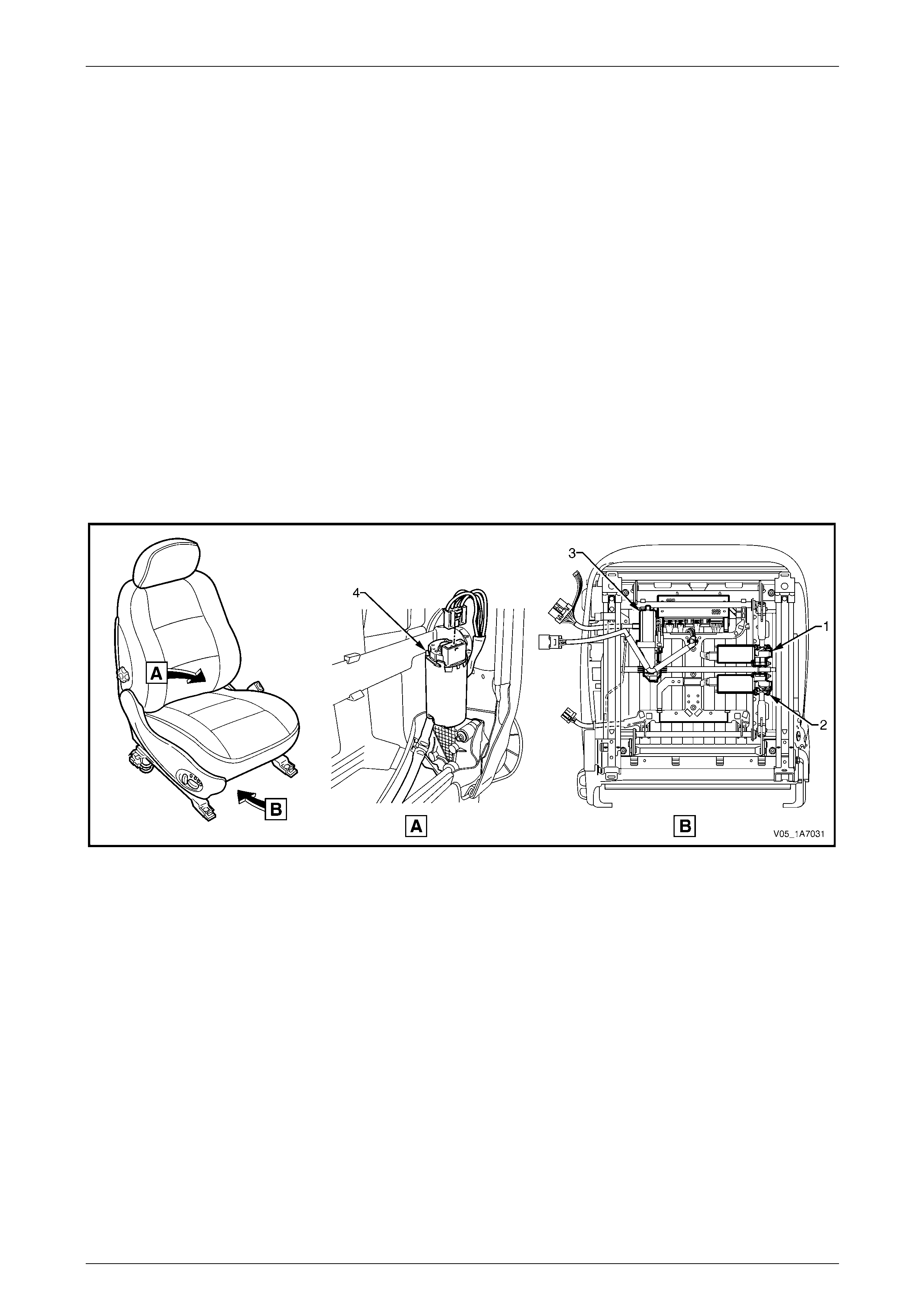
Seat Assemblies Page 1A7A–15
Page 1A7A–15
Seat Covers
Two seat cover construction methods are used for the front seat assemblies. Surebond t ype cloth covers are not
serviced separately as they ar e glued to the seat pad. Hook and Lo op type covers are fully serviceable as they are
attached within the grooves of the seat pad with a Velcro type material.
Electric Seat Operation
Depending on Mode l Level of the vehicle, the following front seat electric movement functions are available:
• four-way – seat cushion front raise/lo wer and rear raise/lower,
• six-way – as four-way plus seat fore/aft, and
• eight-way – as six-way plus seat-back recline.
Referring to Figure 1A7A – 1, four electric motor and gearbox assemblies provide the movement of the front seat, one
each, where fitted, for:
• front raise/lower movement (1),
• rear raise/lower movement (2),
• seat fore/aft movement (3),
• seat-back recline (4).
Figure 1A7A – 1
Each function is independentl y controlled. Alternatively, if desired the front and rear raise/lower movement can be
performed together to raise or lower the complete seat.
Raise/Lower Movement
Two lift motor and gearbox assembli es (1 & 2, refer to Figure 1A7A – 1) are attached to the inboard side of the track and
height adjust assembly: one for front and the other for rear raise/lo wer movement. When a lift motor is operating, it drives
the gearbox which draws in or extends a mating worm shaft. This in turn operates on an arm and cross-shaft.
The cross-shaft is connected to another arm on the opposite side of the track and height adjust assembly and allows the
raising or lowering of that portion (front or rear) of the seat.
Fore/Aft Movement
To provide seat fore/aft movement, the motor and gearbox assembly (3, refer to Figure 1A7A – 1) is connected to a shaft
geared at each end. Within e ach seat track, the shaft gear is meshed upon a rack, providing fore/aft movement.
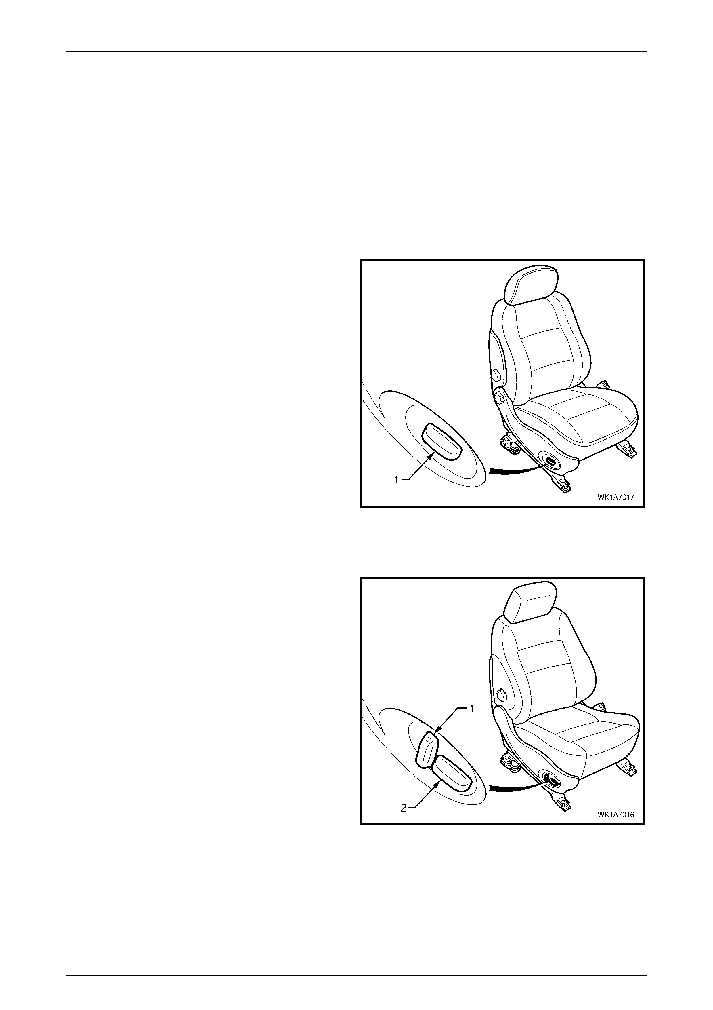
Seat Assemblies Page 1A7A–16
Page 1A7A–16
Recline Movement
Seat-back recline movement is provided by the recline motor and gearbox assembly (4, refer to Figure 1A7A – 1), which
is attached to the seat-back frame. A shaft from the gearbo x is fitted with a drive gear at each end and is meshed with a
driven gear attached to each seat-back frame pivot. Motor operation causes rotation of the drive gear, which turns the
driven gear and seat-back frame, thereby altering the seat-back recline angle.
All motors reverse direction when the pol arity at the wiring terminals is reversed, resultin g in seat movement in the
opposite direction. During seat position adjustment, the drive motors will cease op eration at the end of their travel via an
internal thermal cut-out switch, even if the seat adjustment switch is held on.
Components making up the seat-back recline mechanism and track and height adjust assembly are not serviced.
Four-way and Six-way Movement Control
Four-way and six-way seat movement is controlled by a
front seat adjustment switch assembly (1), which is fitted to
the outer side of each front seat.
For the four-way seat, the switch provides indepe ndent
control of the front and rear raise/lower movements.
The six-way front seat adjustment switch provides fore/aft
movement in addition to the four- way movements.
To adjust the seat:
• Operate the switch up or down to raise/lower the seat.
• Operate the front of the switch up or down to
raise/lower the front of the seat.
• Operate the rear of the switch up or down to
raise/lower the rear of the seat.
• Operate the switch forward or backward to move the
seat fore/aft.
For further information, refer to the Owner's Handbook. Figure 1A7A – 2
Eight-way Movement Control
The eight-way front seat adjustment switch has an
additional knob (1) which provides control of the seat-back
recline movement. The knob (2) provi des the same
functions as six-way seats.
To adjust the seat recline:
• Operate the recline knob to adjust the angl e of the
seat-back. The seat-back moves in the same direction
to which the switch is moved.
For further information, refer to the Owner's Handbook.
Figure 1A7A – 3
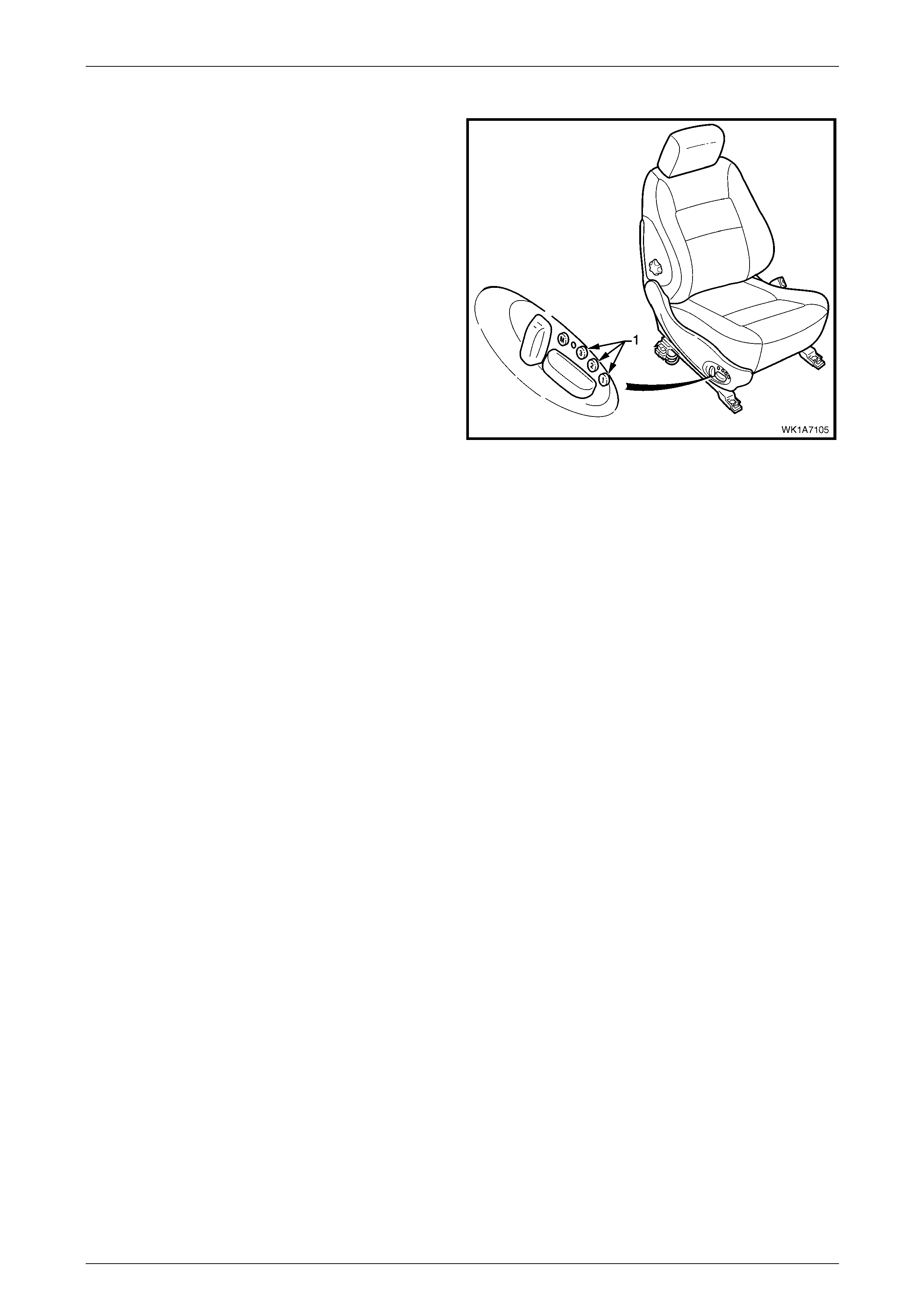
Seat Assemblies Page 1A7A–17
Page 1A7A–17
Memory Seat Position System
The driver’s seat in Level 5 vehicles is fitted wit h a memory
seat position system.
The memory seat position system allo ws the driver to adjust
the seat to any of the positions stored in memory by
pressing one of the three memory buttons (1).
In addition, on keyless entry to the vehic le, the memory seat
position system through the Body Control Module (BCM),
recognises which ignition key has been used (Priority 1 or
Priority 2) and adjusts the seat position to the driver’s
preferred set position.
Audible and visual feedback for the various fu nctions of the
memory seat position system is provided. The s ystem has a
green LED and a chime which are used to i ndicate memory
saves, the recall of priority memory numbers and for seat
diagnostic procedures.
Hall-effect sensors integrated into each of the motor
assemblies are used to monit or the positi on of the seat.
Figure 1A7A – 4
The seat memory module, mounted under the front seat, has a non-volatile memory. While disconnecting the battery will
not erase the seat memory settings, the seat will require recalibrating to reset the sensor stop values within the memory
control module.
NOTE
Some of the procedures relating to memory seat
diagnosis detailed i n 4 Diagnostics – Front Seat,
Memory and Rear-view Mirror, Level 5 require
the use of both the Priority 1 Key and the Priorit y
2 Key.
Priority Keys (Level 5 Vehicles Only )
On level 5 vehicles, the driver's seat movement is a function of the priority keys. Priority key 1 and priority key 2 move the
driver's seat and exterior mirrors to the positions in which they were set when that key was last inserted into the ignition
switch. When the vehicle is unlocked usi ng the Unlock button on a priority key and that priority key is inserted into the
ignition switch, the vehicle identifies the pri ority key and:
• adjusts the position of the driver's seat,
• adjusts the position of the exterior mirrors to the last position used for that key, and
• if the mirror dip function is activated, adjusts the position of the passenger's exterior mirror when the transmission
selector is placed in reverse.
The driver's seat moves to the last position used for that priority key if:
• that was a memory button position, or
• the seat was adjusted without memorising the position.
The driver's seat moves to the alternate prio rity key position only after pressing the unlock button on the alternate priority
key. If the alternate priority key is not used to unlock the vehicle, that priority key will adjust all personalised settings (for
example, exterior mirror angles, radio and climate control), except the driver's seat.
If activated, the left exterior mirror dip function is linked to the seat and priority key memory (that is, each seat memory
position also stores the left exterior mirror DIP positio n, if activated).
For further information, refer to the Owner's Handbook.

Seat Assemblies Page 1A7A–18
Page 1A7A–18
Memory Buttons
The seat can store three different memory settings. To recall a stored memory seat and exterior mirror position, press
and hold one of the memory buttons. After the seat has reached its memorised position, release the me mory button. If
the memory button is released before the seat reaches its memorised position, the seat stops moving.
To change a memory position:
1 Adjust the seat with the eight-way front seat adjustment switch.
2 Adjust the exterior mirrors (including the dip positio n).
3 Place the transmission selector in either park or neutral, then turn on the ignition switch.
4 Press the mirror DIP / memory store button (1, 2 or 3) within five seconds. (Two audible chimes are generated
when a new memory position has been stored.)
5 Place the transmission select or in reverse and wait for the passenger's mirror to be returned from the DIP angle to
complete saving the mirror position into memory, refer to Using the Exterior Mirrors.
Using the Exterior Mirrors
The right exterior mirror and left exterior mirror can be adjusted using the rear-view mirror switch on the driver’s door
armrest when the ignition is on.
To operate the right exterior mirror or left exterior mirror:
1 Turn on the ignition s witch.
2 Move the rocker switch on the rear-view mirror switch to the position to control the right or left exterior mirror.
3 Press the rear-view mirror switch in one of the directions indicated by one of the moulded 'dots' on the edge of the
rear-view mirror switch to move the mirror up, down, left or right.
Adjusting the DIP View
To change the mirror dip posit ion and save it in memory:
1 Turn the ignition switch on.
2 Place the transmission select or in reverse.
3 Ensure the DIP angle is switched on; the left exterior mirror moves to the current DIP position.
4 Adjust the left exterior mirror using the rear-view mirror switch.
5 Place the transmission selector out of reverse.
6 Press the mirror DIP button, then the desired memory store button (1, 2 or 3) to save the mirror dip position into
memory.
For further information, refer to the Owner's Handbook.
Toggle DIP Function On / Off
When the mirror DIP function is activated, the left exterior mirror moves to the position set, typically enabling the driver to
see the kerb more clearly. If activated, the DIP function is operational when the ignition is on and the transmission
selector placed in reverse.
To toggle between the dip view and normal view, press the mirror DIP / memory store button:
• When the DIP function is turned on, two audible chimes are generated.
• When the DIP function is turned off, one audible chime is generated.
For further information, refer to the Owner's Handbook.
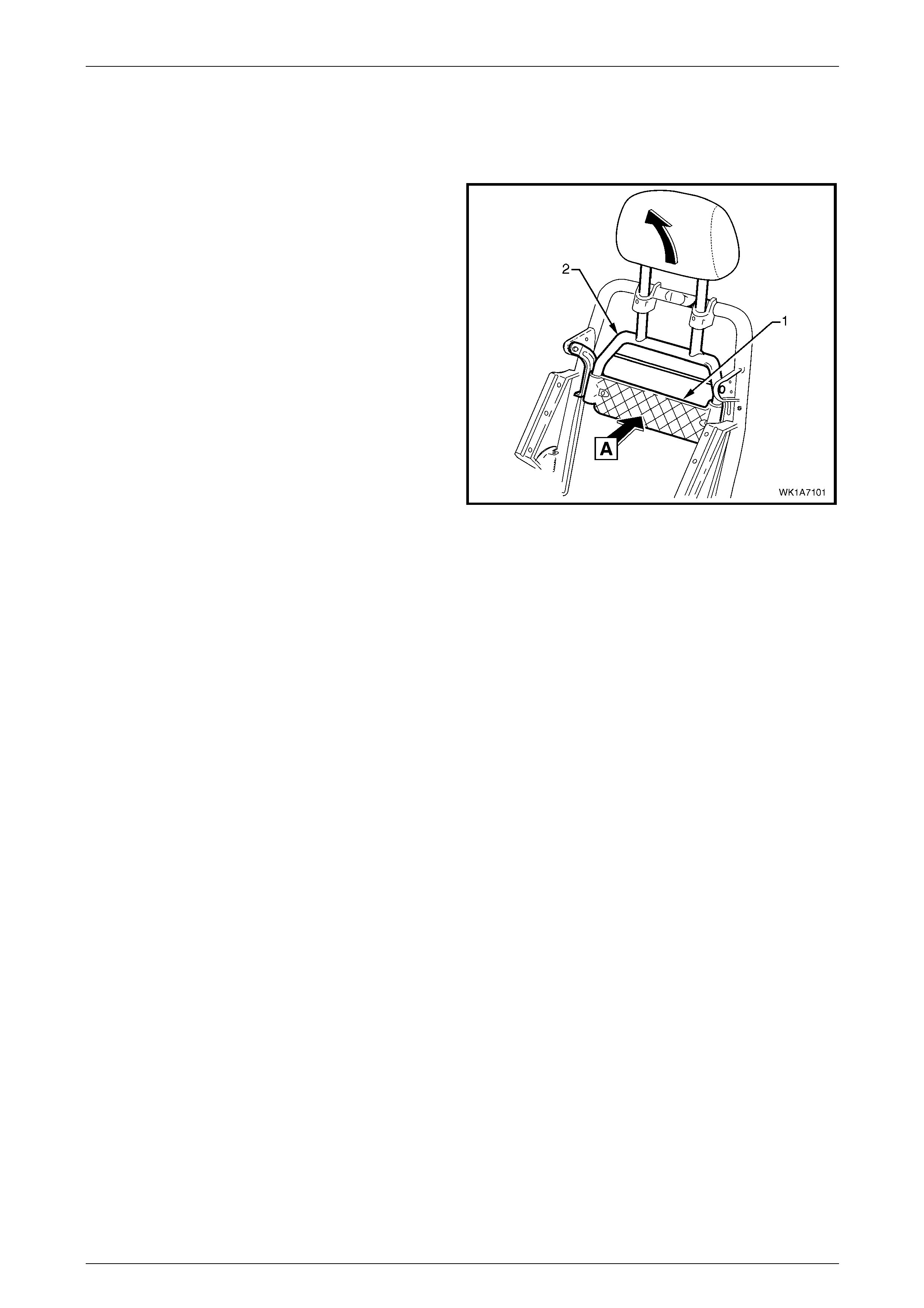
Seat Assemblies Page 1A7A–19
Page 1A7A–19
Active Head Restraints
The front seats fitted to Level 4 and 5 vehicles feature active head restraints. During a rear-end collision, active head
restraints are designed to move upward and forward to support the occupant's head and reduce neck injuries.
The impact force from the collision pushes the vehicle (and
seat) forward. As the vehicle moves forward at a speed
greater than the occupant’s body can react to, the body is
moved into the seat (A) pushing on the active hea d restraint
support strap (1).
Due to the pivoting of the active head restrain t frame (2), the
frame along with the head rest raint moves upward and
forward, supporting and limiting rearward travel of the
occupant's head.
Figure 1A7A – 5

Seat Assemblies Page 1A7A–20
Page 1A7A–20
1.2 Rear Seat General Description
Depending on vehicl e Model Level, the rear seats fitted may feature:
• The option of a two or three passenger rear seat cushion for Level 5,
• A first aid kit pouch in the right-hand rear seat-back assembl y, Levels 4 a nd 5,
• Centre arm rest with deposit box and cup holder, Levels 4 and 5,
• Standard leather trim for Levels 3 and 5 and optional for Levels 2 and 4,
• Centre head restraint for Levels 3 – 5.
Seat Covers
Three seat cover construction methods are us ed for the rear seat assemblies:
• Surebond
• Hook and Loop
• Conventional Pull-down
Surebond
Surebond rear seat assemblies are fitted to Level 1 vehicles and have cloth covers that are not serviced separatel y, as
they are glued to the rear seat cushion and seat-back pads.
Hook and loop
Hook and loop rear seat assemblies are fitted to Level 3 vehicles are fully serviced. They are attached to the rear seat
cushion and seat-back pads using a hook and loop system.
Conventional pull-down
Conventional pull-down rear seat assemblies are fitted to Level 2, 4 and 5 vehicles. Retainer wires are fitted within
casings that are part of the rear seat covers. Hog rings are then used to attach the covers to wires that are moulded
within the cushion or seat-back pads.
For all vehicles, the rear seat cushion frame is serviceable and attaches to the cushion cover retainer wires with hog
rings. The rear seat-back assemblies have the frame moulded as part of the rear seat-back cushion pad and if a
replacement of either part is required, the pad and frame need to be replaced as an assembly.

Seat Assemblies Page 1A7A–21
Page 1A7A–21
2 Diagnostics – Front Seat,
Level 1
This Section provides charts to assist in the diagnosis and repa ir of front seats. Refer to 5.1 Usage Ch art , for a full listing
of the different types of seats fitted to vehicles. Included in that Section are illustrated parts breakdowns of the various
seats.
2.1 Prerequisites
Safety Requirements
When operating the seat as part of any Steps
in the diagnostic tables, ensure that fingers
and limbs are clear of mo ving parts.
Equipment
The following equipment is required to diagnose the seats:
• An unpowered test lamp with a current dra w of less than 3 A.
• A digital multimeter with a minimum impedance of 10 MΩ.
Testing Procedures
The following points must be adhered to
when performing diagnostic testing on
components:
• Take care when using testing equipment
to diagnose wiring harness connectors. It
is preferred that the technician backprobe
the connector to avoid terminal damage.
• When tests are required on connector
terminals, use the adapters in the
connector adapter kit KM–609 to prevent
damage to the terminals.
• Unless the multimeter being used has an
auto-ranging function, ensure the correct
range is selected.
• When backpro bing connectors, ensure the
test lamp ground lead is connected to an
appropriate ground point on the vehicle.
Ensure this ground point is not part of the
circuit being tested.
NOTE
When following the steps in th e diagnostic tables,
perform them in the order cited. If the required
nominal value or result is not achi eved, rectif y t he
problem before proceeding any further.

Seat Assemblies Page 1A7A–22
Page 1A7A–22
2.2 Mechanical Diagnosis
Lumbar Support Inoperative
Introduction
This test is used to aid in diagnosing the lumbar support assembly.
Test Description
The following numbers refer to the step numbers in the diagnostic table:
1 Checks if the lumbar support knob is properly engaging the lumbar support adjuster. Check the knob for cracks and
worn splines.
2 Checks if the lumbar support assembly is damage d or worn and if the retaining springs are serviceable and
securely attached to the seat-back frame assembly.
3 Checks if the lumbar support assembly is serviceable and if the lumber support assembly strap is operating
correctly within the guide rails.
Diagnostic Table
Step Action Yes No
1 Remove the lumbar support knob, refer to 5.9 Lumbar Su pport Knob
Assembly.
Is the lumbar support adjust knob serviceable? Go to Step 2
Replace the knob,
refer to 5.9 Lumbar
Support Knob
Assembly
2 1 Remove the seat-back cover.
2 Inspect the lumbar support retainers and spri ngs.
Are the lumbar support retaining spri ngs serviceable and securely
attached to the seat-back frame assembly? Go to Step 3
Replace or reattach
the retaining
springs, refer to
5.11 Front
Seat-back Frame
Assembly
3 1 Visually inspect the lumbar support assembly. Check for broken
or worn parts.
2 Check the strap running across the lumber s upport assembly is
serviceable and running freely within the guide rails.
NOTE
You may need to attach the lumber support knob to
actuate the strap.
Is the lumbar support assembly serviceabl e? System serviceable
Replace lumbar
support assembly or
resecure lumbar
support assembly
strap ensuring strap
is not binding with
guide rails, refer to
5.11 Front
Seat-back Frame
Assembly
When all diagno sis and repairs are completed, ch eck the system for correct operation.

Seat Assemblies Page 1A7A–23
Page 1A7A–23
Seat-back Recline Forward and/or Aft Function is Inoperative
Introduction
This test is used to aid in diagnosing the recline function of the seat assembly.
Test Description
The following numbers refer to the step numbers in the diagnostic table:
1 Checks if the recliner knob is properly engaging the recliner shaft. Check the knob for cracks and worn splines.
Diagnostic Table
Step Action Yes No
1 Remove the recliner knob, refer to 5.4 F ront Seat Outer Side Cover
Assembly.
Is the recliner knob serviceable?
Replace the front
seat-back frame
assembly, refer to
5.11 Front
Seat-back Frame
Assembly
Replace the recliner
knob, refer to 5.4
Front Seat Outer
Side Cover
Assembly
When all diagno sis and repairs are completed, ch eck the system for correct operation.
Four-way Seat Fore/Aft Movement Function is Inoperative or is Not Smooth
Introduction
This test is used to aid in diagnosi ng the fore/aft movement function of the seat being inoperative or the action of the seat
through the range of movement is not smooth.
Test Description
The following numbers refer to the step numbers in the diagnostic table:
1 Checks if there are any items obstructing the guide rails which may stop or hinder the seat movement.
2 Checks if the guide rails have adequate lubricant appli ed to provide a smooth operation for the seat.
3 Checks if the linkage assembly between the adjustment lever and locking tangs is worn or damaged. The lockin g
tangs must disengage from the guide rails be fore the seat will move.
4 Checks if the guide rails have been damaged. Any binding b etween the inner and outer guide rails will result in
poor operation of the fore and aft movement.
Diagnostic Table
Step Action Yes No
1 Are the guide rails free from obstructions? Go to Step 2 Remove the
obstructing item
2 Are the guide rails adequately lubricated?
Go to Step 3
Apply a small
amount of grease
type NLGI No. 1
Lithium Grease
(with 9% Zinc
Oxide) to the rails
3 Do the locking tangs disengage the guide rails when the sea t fore and
aft adjustment lever is raised to its full movement?
Go to Step 4
Replace the track
and height adjust
assembly, refer to
5.13 Track and
Height Adjust
Assembly
4 Do the guide rails bind at any point of travel during the fore and aft
movements of the seat? Replace the track
and height adjust
assembly, refer to
5.13 Track and
Height Adjust
Assembly System serviceable
When all diagno sis and repairs are completed, ch eck the system for correct operation.

Seat Assemblies Page 1A7A–24
Page 1A7A–24
2.3 Electrical Diagnosis – Four-way/Six-way
Seat
The charts in this Section are used to aid in diagnosing faults on four-way and six-way seat assemblies. To aid in the use
of the diagnostic tables, refer to Wiring Diagram – Four-way/Six-way Seat and
Connector Chart – Four- way/Six-way Seat.
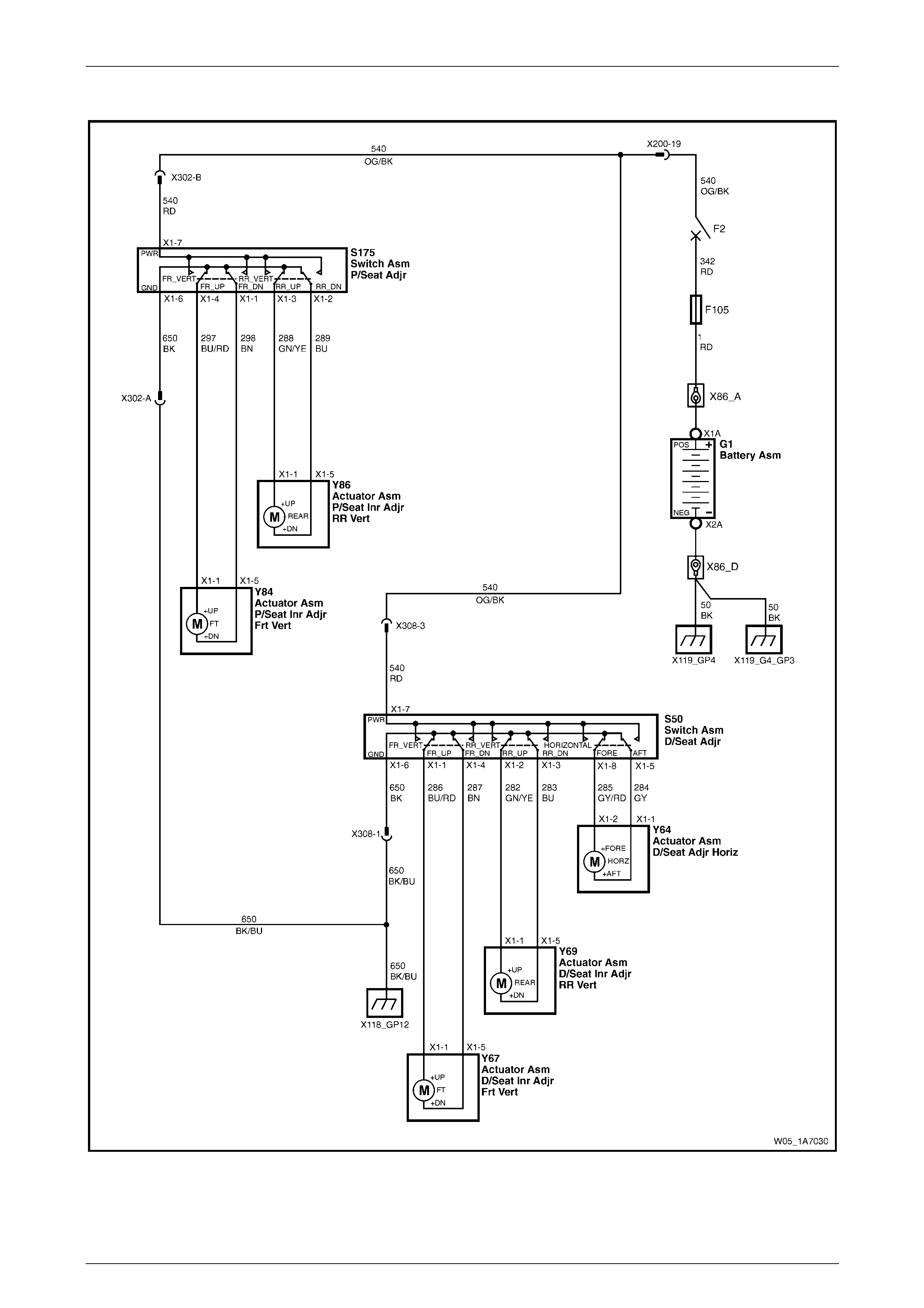
Seat Assemblies Page 1A7A–25
Page 1A7A–25
Wiring Diagram – Four-way/Six-way Seat
Figure 1A7A – 6
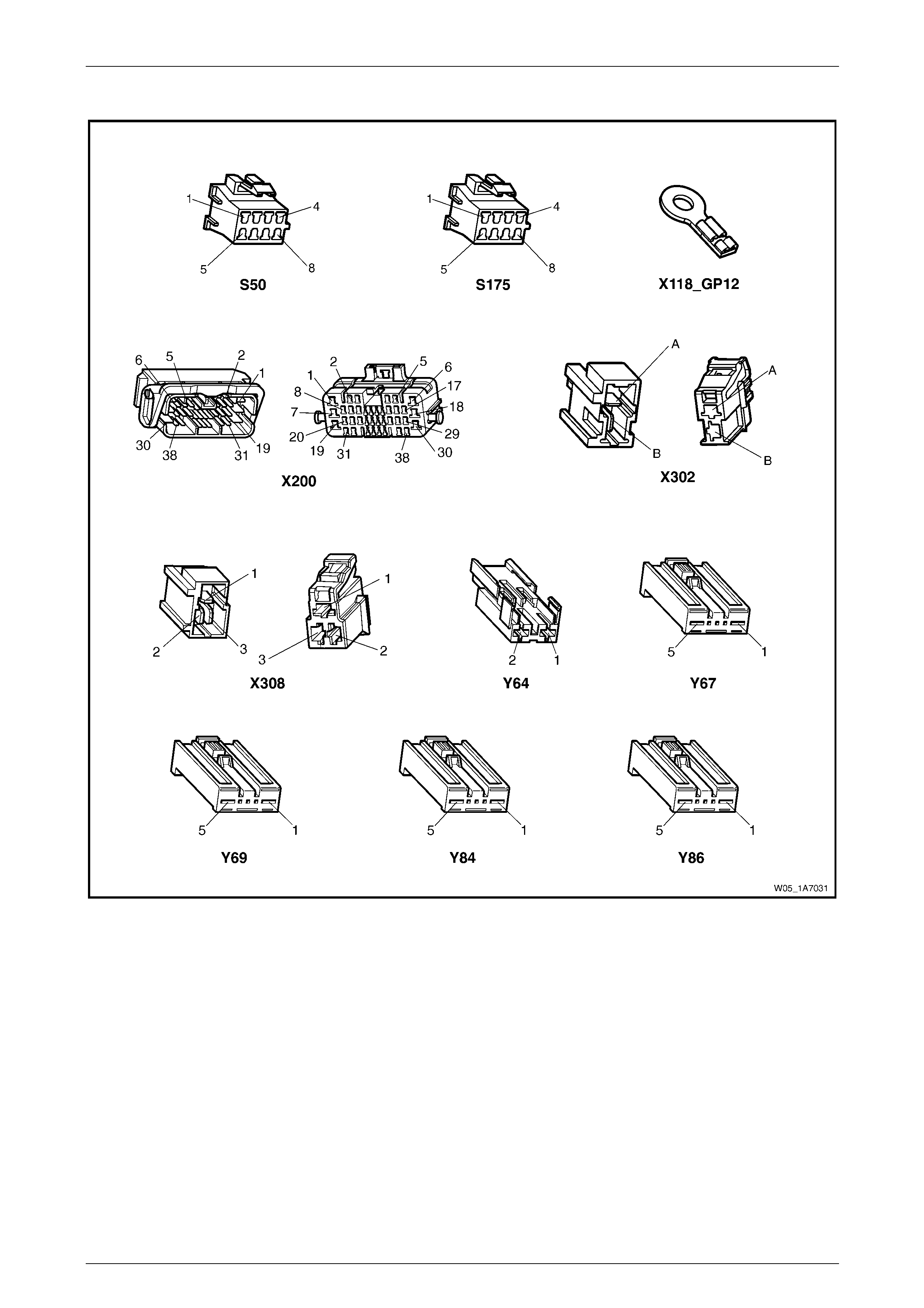
Seat Assemblies Page 1A7A–26
Page 1A7A–26
Connector Chart – Four-way/Six-way Seat
Figure 1A7A – 7

Seat Assemblies Page 1A7A–27
Page 1A7A–27
Neither Seat Adjustment Switch Functions Operate
Introduction
This test is used to aid in diagnosing the seat power and ground circuits, if neither seat operates when either seat
adjustment switch is operated.
Test Description
The following numbers refer to the step numbers in the diagnostic table:
1 Checks if battery voltage is more than 11.5 V. The seat motors require mo re than 11.5 V to operate correctly.
2 Checks if circuit breaker F2 located on the passenger com partment fuse and relay panel assembl y is tripped.
Isolates if circuit breaker F2 is the fault affecting the circuit between the battery and conne ctor X200 pin 19.
3 Checks if fusible link F105 located on the engine compartment fuse and relay panel assembly is serviceable.
Isolates if the fusible link is the fault affecting the circuit between the battery and connector X200 pin 19.
4 Checks if connector X200 is secure.
5 Checks if there is battery voltage at connector X200 pin 19. Isolates if the fault is between the battery and
connector X200 pin 19. If the fault in the circuit is between connectors X200 pin 19 and either X3 08 pin 3 or
X302 pin B, only o ne seat will operate.
6 Checks if there is battery voltage at circuit breaker F2. Isolates whether the fault is between the b attery and circuit
breaker F2 or bet ween circuit breaker F2 an d connector X200 pin 19.
7 Checks if there is battery voltage at fusible link F105. Isolates whether the fault is between the battery and fusible
link F105 or between fusible li nk F 105 and circuit breaker F2.
8 Checks if the ground point associated with the system is serviceable.
Diagnostic Table Notes
1 For all wiring harness fault diagnoses, refer to Section 12P Wiring Diagram s.
2 For wiring harness repairs, refer to Section 12P Wiring Diagrams.
3 Refer to Section 12O Fuses, Relays and Wiring Harnesses for harness routeing.
4 If the fault is deemed to be intermittent, refer to Section 12P Wiring Diagrams.

Seat Assemblies Page 1A7A–28
Page 1A7A–28
Diagnostic Table
Step Action Yes No
1 Check the battery voltage, refer to Section 12A Battery.
Is the battery voltage more than 11.5 V? Go to Step 2
Refer to Section
12A Battery for
further diagnosis
2 Inspect circuit breaker F2, refer to Section 12O Fuses, Relays and
Wiring Harnesses.
Is circuit breaker F2 tripped?
Allow the circuit
breaker to reset
(refer to Note 3).
If the circuit breaker
trips again, repair or
replace circuit 540
(refer to Note 2) Go to Step 3
3 Inspect fusible link F105, refer to Section 12O Fuses, Relays and
Wiring Harnesses.
Is fuse F105 serviceable?
Go to Step 4
Replace the fusible
link.
If the fusible link
becomes
unserviceable
again, repair or
replace circuit 342
(refer to Note 2)
4 Is connector X200 secure (refer to Note 3)? Go to Step 5 Ensure the
connector is secure
5 Backprobe connector X200 pin 19 with a test lamp (refer to Note 1).
Does the test lamp illuminate? Go to Step 8 Go to Step 6
6 1 Remove circuit breaker F2 from the passenger compartment
fuse and relay panel assembly.
2 Using a test lamp, probe connector X12 9 - X45 – 2 (refer to Note
1).
Does the test lamp illuminate?
Repair or replace
circuit 540 between
circuit breaker F2
and connector
X200 pin 19 (refer to
Note 2) Go to Step 7
7 1 Remove fusible link F105.
2 Using a test lamp, probe connector X18-105 (refer to Note 1).
Does the test lamp illuminate?
Repair or replace
circuit 342 between
fusible link F105
and circuit breaker
F2 (refer to Note 2)
Repair or replace
circuit 1 between
the battery and
fusible link F105
(refer to Note 2)
8 Ensure ground point X118 – GP12 (located in the middle of the
transmission tunnel) is secure and has good contact with the vehicle
structure.
Is the ground point secure to the vehicle with a good contact?
Repair or replace
circuit 650 (refer to
Note 2) Repair ground point
When all diagno sis and repairs are completed, ch eck the system for correct operation.

Seat Assemblies Page 1A7A–29
Page 1A7A–29
None of the Driver’s Seat Adjustment Switch Functions Operate
Introduction
This test is used to aid in diagnosing the driver’s seat adjustment switch when none of the switch functions operate. The
test diagnoses the driver’s seat adjustment switch and associated power and ground circuits.
Test Description
The following numbers refer to the step numbers in the diagnostic table:
1 Checks if all of the passenger's seat functions work. If none of them work, the fault is not isolated to the driver’s
seat only.
2 Checks if there is battery power at connector X308 pi n 3. Isolates if there i s a fault in circuit 540 between
connectors X200 pin 19 and X308 pin 3.
3 Checks if all the connectors required for the seat to operate effectively are in place a nd positively connected.
4 Checks if there is battery power at connector S50 – X1 pi n 7. Isolates if there is a fault in circuit 540 between
connectors S50 – X1 pin 7 and X308 p in 3.
5 Checks if the driver’s seat adjustment switch is serviceable.
6 Checks if there is continuity between connectors S50 – X1 pin 6 and X308 pin 1 which supplies the ground circuit
for the driver’s seat adjustment switch. Isolates whether there is a fault in circuit 650 between the switch and
connector X308 pin 1 or between connector X308 pin 1 and the ground point.
Diagnostic Table Notes
1 For all wiring harness fault diagnoses, refer to Section 12P Wiring Diagram s.
2 For wiring harness repairs, refer to Section 12P Wiring Diagrams.
3 Refer to Section 12O Fuses, Relays and Wiring Harnesses for harness routeing.
4 If the fault is deemed to be intermittent, refer to Section 12P Wiring Diagrams.

Seat Assemblies Page 1A7A–30
Page 1A7A–30
Diagnostic Table
Step Action Yes No
1 Are all of the passenger’s seat adjustment switch functions
inoperative? Refer to Neither
Seat Adjustment
Switch Functions
Operate in this
Section Go to Step 2
2 Backprobe connector X308 pin 3 with a test lamp (refer to Note 1).
Does the test lamp illuminate?
Go to Step 3
Repair or replace
circuit 540 between
connectors
X200 pin 19 an d
X308 pin 3 (refer to
Note 2)
3 Are the following connectors secure (refer to Note 3)?
• S50
• X308
• Y64
• Y67
• Y69 Go to Step 4
Ensure the
connectors are
secure
4 Backprobe connector S50 – X1 pin 7 with a test lamp (refer to Note 1).
Does the test lamp illuminate?
Go to Step 5
Repair or replace
circuit 540 between
connectors
S50 – X1 pin 7 and
X308 pin 3 (refer to
Note 2)
5 1 Remove the driver’s seat adjustment switch from the seat, refer
to 5.4 Front Seat Outer Side Cover Assembly.
2 Test the driver’s seat adjustment switch, refer to 2.5 Six-way
Seat Adjustment Switch Test.
Is the driver’s seat adjustment switch serviceable? Go to Step 6
Replace the driver’s
seat adjustment
switch, refer to 5.4
Front Seat Outer
Side Cover
Assembly
6 1 Backprobe connector X30 8 pin 1 with a test lamp (refer to Note
1).
2 Operate the driver’s seat adjustment switch in any of the
available directions.
Does the test lamp illuminate?
Repair or replace
circuit 650 between
connector X308 pin
1 and ground point
X118 – GP12 (refer
to Note 2)
Repair or replace
circuit 650 between
connectors
S50 – X1 pin 6 and
X308 pin 1 (refer to
Note 2)
When all diagno sis and repairs are completed, ch eck the system for correct operation.

Seat Assemblies Page 1A7A–31
Page 1A7A–31
Front/Rear of the Driver's Seat Does Not Raise and/or Lower
Introduction
This test is used to aid in diagnosing the front and/or the rear of the driver's seat not raising and/or lowering. The test
diagnoses the seat adjustmen t switch and the motor circuits.
Test Description
The following numbers refer to the step numbers in the diagnostic table:
1 Checks if the driver's seat adjustment switch assembly operates the seat in any direction. Isolates whether there is
a battery or ground fault affecting the seat operation.
2 Checks if all the connectors required for the seat to operate effectively are in place a nd positively connected.
3 Checks if the driver's seat adjustment switch is serviceable.
4 Confirms whether the rear of the seat raises or lowers. Isolates if the seat rear lift motor and circuit of the seat is the
fault.
5 Confirms whether the front of the seat raises or lo wers. Isolates if the seat front lift motor and circuit of the seat is
the fault.
6 Checks if there is battery power to the seat rear lift motor at connector Y69 – X1 pin 1. Isolates if there is a fault in
circuit 282 that supplies battery po wer to the motor to raise the rear of the seat.
7 Checks if there is battery power to the seat rear lift motor at connector Y69 – X1 pin 5. Isolates whether the fault is
in circuit 283 that supplies battery power to the motor to lower the rear of the seat or the motor is faulty. As
reversing the polarity changes the direction of the motor, this Step also confirms if the ground circuit from Step 6 is
serviceable.
8 Checks if there is battery power to the seat front lift motor at connector Y67 – X1 pin 1. Isolates if there is a fault in
circuit 286 that supplies battery po wer to the motor to raise the front of the seat.
9 Checks if there is battery power to the seat front lift motor at connector Y67 – X1 pin 5. Isolates whether the fault is
in circuit 287 that supplies battery power to the motor to lower the front of the seat or the motor is faulty. As
reversing the polarity changes the direction of the motor, this Step also confirms if the ground circuit from Step 8 is
serviceable.
Diagnostic Table Notes
1 For all wiring harness fault diagnoses, refer to Section 12P Wiring Diagram s.
2 For wiring harness repairs, refer to Section 12P Wiring Diagrams.
3 Refer to Section 12O Fuses, Relays and Wiring Harnesses for harness routeing.
4 If the fault is deemed to be intermittent, refer to Section 12P Wiring Diagrams.

Seat Assemblies Page 1A7A–32
Page 1A7A–32
Diagnostic Table
Step Action Yes No
1 Does the driver's seat adjustm ent switch operate the seat correctly in
any of the six directions?
Go to Step 2
Refer to None of the
Driver’s Seat
Adjustment Switch
Functions Operate
in this Section
2 Are the following connectors secure (refer to Note 3)?
• S50
• Y67
• Y69 Go to Step 3
Ensure the
connectors are
secure
3 1 Remove the driver's seat adjustment switch from the seat, refer
to 5.4 Front Seat Outer Side Cover Assembly.
2 Test the driver's seat adjustment s witch, refer to 2.5 Six-way
Seat Adjustment Switch Test.
Is the driver's seat adjustment switch serviceable? Go to Step 4
Replace the driver's
seat adjustment
switch, refer to 5.4
Front Seat Outer
Side Cover
Assembly
4 Operate the driver's seat adjustment switch to raise or lower the rear
of the seat.
Does the rear of the seat raise and lo wer? Go to Step 5 Go to Step 6
5 Operate the driver's seat adjustment switch to raise or lower the front
of the seat.
Does the front of the seat raise and lower? System serviceable Go to Step 8
6 1 Backprobe connector Y69 – X1 pin 1 with a test lamp (refer to
Note 1).
2 Operate the driver's seat adjustment switch to raise the rear of
the seat.
Does the test lamp illuminate? Go to Step 7
Repair or replace
circuit 282 (refer to
Note 2)
7 1 Backprobe connector Y69 – X1 pin 5 with a test lamp (refer to
Note 1).
2 Operate the driver's seat adjustment switch to lower the rear of
the seat.
Does the test lamp illuminate?
Replace the seat
rear lift motor, refer
to 5.16 Front Seat
Lift Motor
Assemblies
Repair or replace
circuit 283 (refer to
Note 2)
8 1 Backprobe connector Y67 – X1 pin 1 with a test lamp (refer to
Note 1).
2 Operate the driver's seat adjustment switch to raise the front of
the seat.
Does the test lamp illuminate? Go to Step 9
Repair or replace
circuit 286 (refer to
Note 2)
9 1 Backprobe connector Y67 – X1 pin 5 with a test lamp (refer to
Note 1).
2 Operate the driver's seat adjustment switch to lower the front of
the seat.
Does the test lamp illuminate?
Replace the seat
front lift motor, refer
to 5.16 Front Seat
Lift Motor
Assemblies
Repair or replace
circuit 287 (refer to
Note 2)
When all diagno sis and repairs are completed, ch eck the system for correct operation.

Seat Assemblies Page 1A7A–33
Page 1A7A–33
Driver’s Seat Fore/Aft Movement Function is Inoperative or not Smooth
Introduction
This test is used to aid in diagnosi ng the fore/aft movement function of the driver’s seat being inoperative or the action of
the seat through the range of movement is not smooth. The test diagnoses the seat adjustment switch and the motor
circuits.
Test Description
The following numbers refer to the step numbers in the diagnostic table:
1 Checks if the driver’s seat adjustment switch operates the seat in any direct ion. Isolates if there is battery power to
the switch assembly.
2 Checks if there are any items obstructing the guide rails, which may stop or hinder the seat movement.
3 Checks if the guide rails and drive shafts have adequate lubricant applied t o provide a smooth operation of the
seat.
4 Checks if the guide rails or drive shafts have been damaged. An y binding between the moving parts will result in
poor operation of the fore and aft movement.
5 Checks if all the connectors required for the seat to operate effectively are in place a nd positively connected.
6 Checks if the driver’s seat adjustment switch is serviceable.
7 Checks if there is battery power to the seat fore/aft movement motor at connector Y64 – X1 pin 2. Isolates if there
is a fault in circuit 285 that supplies battery power to the motor to move the seat forward.
8 Checks if there is battery power to the seat fore/aft movement motor at connector Y64 – X1 pin 1. Isolates whether
the fault is in circuit 284 that supplies battery power to the motor to move the seat aft or the motor is faulty. As
reversing the polarity changes the direction of the motor, this Step also confirms if the ground circuit from Step 7 is
serviceable.
Diagnostic Table Notes
1 For all wiring harness fault diagnoses, refer to Section 12P Wiring Diagram s.
2 For wiring harness repairs, refer to Section 12P Wiring Diagrams.
3 Refer to Section 12O Fuses, Relays and Wiring Harnesses for harness routeing.
4 If the fault is deemed to be intermittent, refer to Section 12P Wiring Diagrams.

Seat Assemblies Page 1A7A–34
Page 1A7A–34
Diagnostic Table
Step Action Yes No
1 Does the driver’s seat adjustment switch operate the seat correctly in
any of the six directions?
Go to Step 2
Refer to None of the
Driver’s Seat
Adjustment Switch
Functions Operate
in this Section
2 Are the guide rails free from obstructions? Go to Step 3 Remove the
obstructing item
3 Are the guide rails and driv e shafts adequately lubricated?
Go to Step 4
Apply a small
amount of grease
type NLGI No. 1
Lithium Grease
(with 9% Zinc
Oxide)
4 Do the guide rails or drive shafts bind at any point of travel during the
fore and aft movement of the seat? Replace the track
and height adjust
assembly, refer to
5.13 Track and
Height Adjust
Assembly Go to Step 5
5 Are the following connectors secure (refer to Note 3)?
• S50
• Y64 Go to Step 6
Ensure the
connectors are
secure
6 1 Remove the driver’s seat adjustment switch from the seat, refer
to 5.4 Front Seat Outer Side Cover Assembly.
2 Test the driver’s seat adjustment switch, refer to 2.5 Six-way
Seat Adjustment Switch Test.
Is the driver’s seat adjustment switch serviceable? Go to Step 7
Replace the driver’s
seat adjustment
switch, refer to 5.4
Front Seat Outer
Side Cover
Assembly
7 1 Backprobe connector Y64 – X1 pin 2 with a test lamp (refer to
Note 1).
2 Operate the driver’s seat adjustment switch to move the seat
forward.
Does the test lamp illuminate? Go to Step 8
Repair or replace
circuit 285 (refer to
Note 2)
8 1 Backprobe connector Y64 – X1 pin 1 with a test lamp (refer to
Note 1).
2 Operate the driver’s seat adjustment switch to move the seat aft.
Does the test lamp illuminate?
Replace the seat
fore/aft movement
motor, refer to 5.17
Front Seat Fore/Aft
Movement Motor
Assembly
Repair or replace
circuit 284 (refer to
Note 2)
When all diagno sis and repairs are completed, ch eck the system for correct operation.

Seat Assemblies Page 1A7A–35
Page 1A7A–35
None of the Passenger's Seat Adjustment Switch Functions Operate
Introduction
This test is used to aid in diagnosing the passenger's seat adjustment switch when none of the switch functions operate.
The test diagnoses the passenger's seat adjustment switch and associated power and ground circuits.
Test Description
The following numbers refer to the step numbers in the diagnostic table:
1 Checks if all of the driver's seat functions work. If none of them work, the fault is not isolated to the passenger's
seat.
2 Checks if there is battery power at connector X302 pin B. Isolates if there is a fault in circuit 540 between
connectors X200 pin 19 and X302 pin B.
3 Checks if all the connectors required for the seat to operate effectively are in place a nd positively connected.
4 Checks if there is battery power at connector S175 – X1 pin 7. Isolates if there is a fault in circuit 540 between
connectors S175 – X1 pin 7 and X302 pin B.
5 Checks if the passenger's seat adjustment switch is serviceable.
6 Checks if there is continuity between connec tors S175 – X1 pin 6 and X302 pin A which supp lies the ground circuit
for the passenger's seat adjustment switch. Isolates whether there is a fault in circuit 650 between the s witch and
connector X302 pin A or between connector X302 pin A and the ground point.
Diagnostic Table Notes
1 For all wiring harness fault diagnoses, refer to Section 12P Wiring Diagram s.
2 For wiring harness repairs, refer to Section 12P Wiring Diagrams.
3 Refer to Section 12O Fuses, Relays and Wiring Harnesses for harness routeing.
4 If the fault is deemed to be intermittent, refer to Section 12P Wiring Diagrams.

Seat Assemblies Page 1A7A–36
Page 1A7A–36
Diagnostic Table
Step Action Yes No
1 Are all of the driver's seat adjustment s witch functions inoperative? Refer to Neither
Seat Adjustment
Switch Functions
Operate in this
Section Go to Step 2
2 Backprobe connector X302 pin B with a test lamp (refer to Note 1).
Does the test lamp illuminate?
Go to Step 3
Repair or replace
circuit 540 between
connectors
X200 pin 19 an d
X302 pin B (refer to
Note 2)
3 Are the following connectors secure (refer to Note 3)?
• S175
• X302
• Y84
• Y86 Go to Step 4
Ensure the
connectors are
secure
4 Backprobe connector S175 – X1 pin 7 with a test lamp (refer to Note
1).
Does the test lamp illuminate?
Go to Step 5
Repair or replace
circuit 540 between
connectors
S175 – X1 pin 7 and
X302 pin B (refer to
Note 2)
5 1 Remove the passenger's seat adjustment switch from the seat,
refer to 5.4 Front Seat Outer Side Cover Assembly.
2 Test the passenger's seat adjustment switch, refer to 2.4 Four-
way Seat Adjustment Switch Test.
Is the passenger's seat adjustment s witch serviceable? Go to Step 6
Replace the
passenger's seat
adjustment switch,
refer to 5.4 Front
Seat Outer Side
Cover Assembly
6 1 Backprobe connector X30 2 pin A with a test lamp (refer to Note
1).
2 Operate the passenger's seat adjustment switch in any of the
available directions.
Does the test lamp illuminate?
Repair or replace
circuit 650 between
connector X302 pin
A and ground point
X118 – GP12 (refer
to Note 2)
Repair or replace
circuit 650 between
connectors
S175 – X1 pin 6 and
X302 pin A (refer to
Note 2)
When all diagno sis and repairs are completed, ch eck the system for correct operation.

Seat Assemblies Page 1A7A–37
Page 1A7A–37
Front/Rear of the Passenger's Seat Does Not Raise and/or Lower
Introduction
This test is used to aid in diagnosing the front and/or the rear of the passenger's seat not raising and/or lowering. The
test diagnoses the seat adjustment switch and the motor circuits.
Test Description
The following numbers refer to the step numbers in the diagnostic table:
1 Checks if the passenger's seat adjustment switch assembly operates the seat in any direction. Isolates if there is a
battery or ground fault affecting the seat operation.
2 Checks if all the connectors required for the seat to operate effectively are in place and positively connected.
3 Checks if the passenger's seat adjustment switch is serviceable.
4 Confirms whether the rear of the seat raises or lowers. Isolates if the seat rear lift motor and circuit of the seat is the
fault.
5 Confirms whether the front of the seat raises or lo wers. Isolates if the seat front lift motor and circuit of the seat is
the fault.
6 Checks if there is battery power to the seat rear lift motor at connector Y86 – X1 pin 1. Isolates if there is a fault in
circuit 288 that supplies battery po wer to the motor to raise the rear of the seat.
7 Checks if there is battery power to the seat rear lift motor at connector Y86 – X1 pin 5. Isolates whether the fault is
in circuit 289 that supplies battery power to the motor to lower the rear of the seat or the motor is faulty. As
reversing the polarity changes the direction of the motor, this Step also confirms if the ground circuit from Step 6 is
serviceable.
8 Checks if there is battery power to the seat front lift motor at connector Y84 – X1 pin 1. Isolates if there is a fault in
circuit 297 that supplies battery po wer to the motor to raise the front of the seat.
9 Checks if there is battery power to the seat front lift motor at connector Y84 – X1 pin 5. Isolates whether the fault is
in circuit 298 that supplies battery power to the motor to lower the front of the seat or the motor is faulty. As
reversing the polarity changes the direction of the motor, this Step also confirms if the ground circuit from Step 8 is
serviceable.
Diagnostic Table Notes
1 For all wiring harness fault diagnoses, refer to Section 12P Wiring Diagram s.
2 For wiring harness repairs, refer to Section 12P Wiring Diagrams.
3 Refer to Section 12O Fuses, Relays and Wiring Harnesses for harness routeing.
4 If the fault is deemed to be intermittent, refer to Section 12P Wiring Diagrams.

Seat Assemblies Page 1A7A–38
Page 1A7A–38
Diagnostic Table
Step Action Yes No
1 Does the passenger's seat adjustment switch operate the seat
correctly in any of the four directions?
Go to Step 2
Refer to None of the
Passenger's Seat
Adjustment Switch
Functions Operate
in this Section
2 Are the following connectors secure (refer to Note 3)?
• S175
• Y84
• Y86 Go to Step 3
Ensure the
connectors are
secure
3 1 Remove the passenger's seat adjustment switch from the seat,
refer to 5.4 Front Seat Outer Side Cover Assembly.
2 Test the passenger's adjustm ent switch, refer to 2.4 Four-way
Seat Adjustment Switch Test.
Is the passenger's seat adjustment s witch serviceable ? Go to Step 4
Replace the
passenger's seat
adjustment switch,
refer to 5.4 Front
Seat Outer Side
Cover Assembly
4 Operate the passenger's seat adjustment switch to raise or lower the
rear of the seat.
Does the rear of the seat raise and lo wer? Go to Step 5 Go to Step 6
5 Operate the passenger's seat adjustment switch to raise or lower the
front of the seat.
Does the front of the seat raise and lower? System serviceable Go to Step 8
6 1 Backprobe connector Y86 – X1 pin 1 with a test lamp (refer to
Note 1).
2 Operate the passenger's seat adjustment switch to raise the rear
of the seat.
Does the test lamp illuminate? Go to Step 7
Repair or replace
circuit 288 (refer to
Note 2)
7 1 Backprobe connector Y86 – X1 pin 5 with a test lamp (refer to
Note 1).
2 Operate the passenger's seat adjustment switch to lower the
rear of the seat.
Does the test lamp illuminate?
Replace the seat
rear lift motor, refer
to 5.16 Front Seat
Lift Motor
Assemblies
Repair or replace
circuit 289 (refer to
Note 2)
8 1 Backprobe connector Y84 – X1 pin 1 with a test lamp (refer to
Note 1).
2 Operate the passenger's seat adjustment switch to raise the
front of the seat.
Does the test lamp illuminate? Go to Step 9
Repair or replace
circuit 297 (refer to
Note 2)
9 1 Backprobe connector Y84 – X1 pin 5 with a test lamp (refer to
Note 1).
2 Operate the passenger's seat adjustment switch to lower the
front of the seat.
Does the test lamp illuminate?
Replace the seat
front lift motor, refer
to 5.16 Front Seat
Lift Motor
Assemblies
Repair or replace
circuit 298 (refer to
Note 2)
When all diagno sis and repairs are completed, ch eck the system for correct operation.
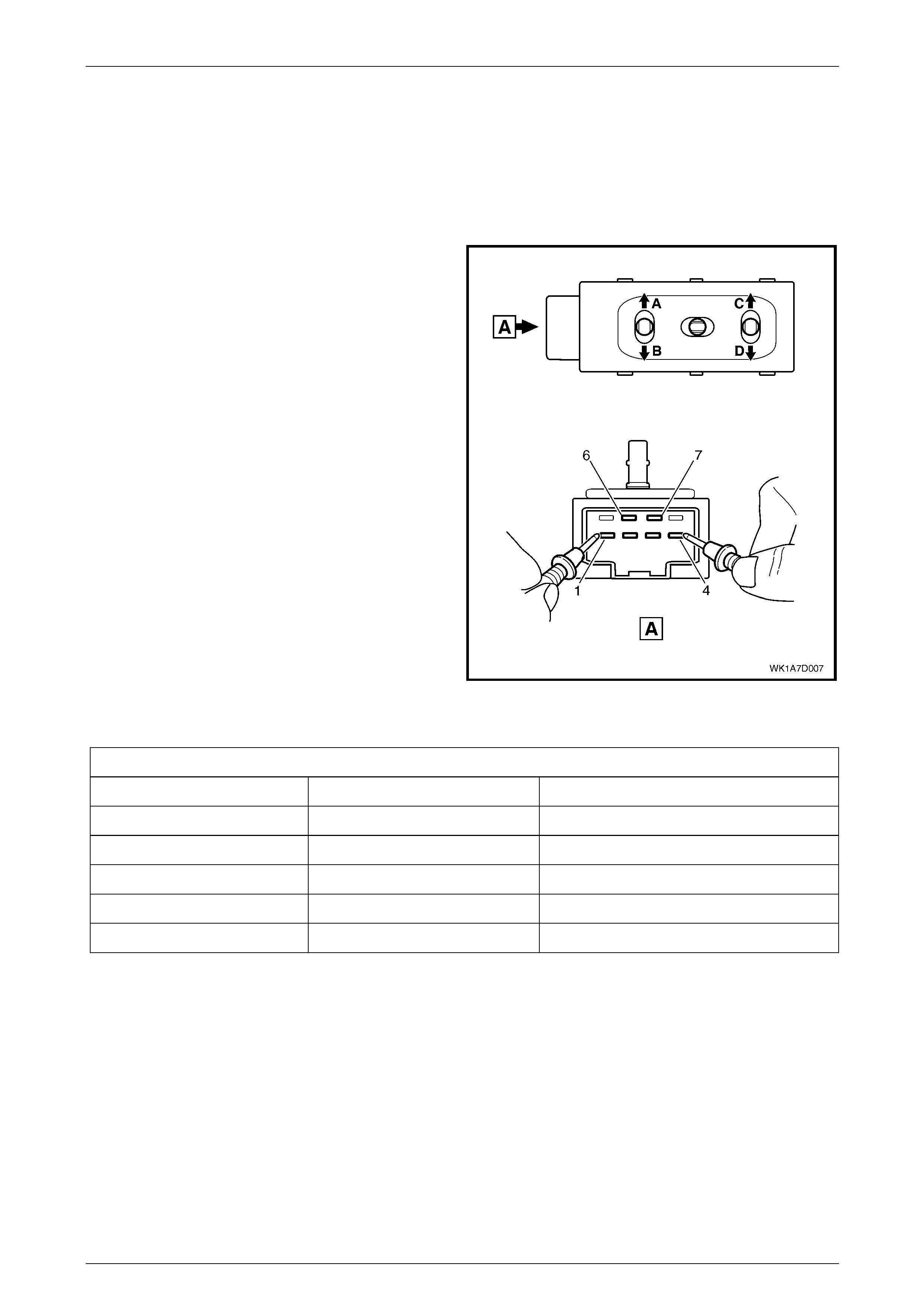
Seat Assemblies Page 1A7A–39
Page 1A7A–39
2.4 Four-way Seat Adjustment Switch Test
The switch is located on the outer side of the seat, attached to the inner side of the front seat outer side cover.
Test
1 Remove the four-way seat adjustment switch, refer to 5.4 Front Seat Outer Side Cover Assembly.
2 Place the switch in the positions as detailed i n the
chart in this Section. Place the probes of the
ohmmeter onto the terminals listed and take the
reading. Compare the reading to the chart.
3 If the switch fails any part of the test, replace the
switch assembly with a serviceable item.
4 Install the four-way seat adjustment s witch, refer to
5.4 Front Seat Outer Side Cover Assembly.
Figure 1A7A – 8
Four-way Seat Adjustment Switch
Switch Position Sw itch Terminals Indication if Switch is Serviceable
Position A 3 and 7 Continuity
Position B 2 and 7 Continuity
Position C 4 and 7 Continuity
Position D 1 and 7 Continuity
Switch in the neutral position 6 and either 1, 2, 3 or 4 Continuity
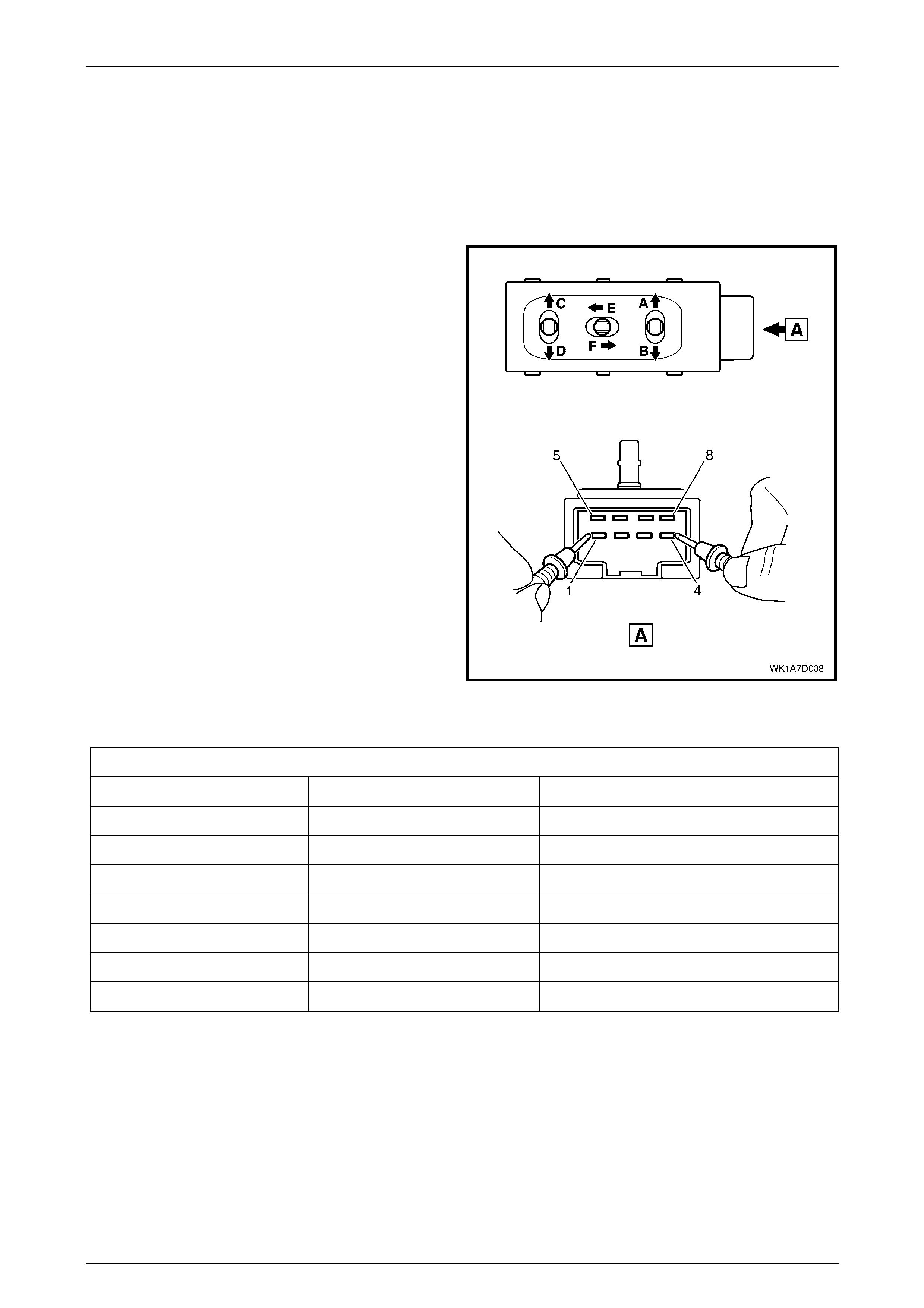
Seat Assemblies Page 1A7A–40
Page 1A7A–40
2.5 Six-way Seat Adjustment Switch Test
The switch is located on the outer side of the seat, attached to the inner side of the front seat outer side cover.
Test
1 Remove the six-way seat adjustment switch, refer to 5.4 Front Seat Outer Side Cover Assembly.
2 Place the switch in the positions as detailed i n the
chart in this Section. Place the probes of the
ohmmeter onto the terminals listed and take the
reading. Compare the reading to the chart.
3 If the switch fails any part of the test, replace the
switch assembly with a serviceable item.
4 Install the six-way seat adjust ment switch, refer to
5.4 Front Seat Outer Side Cover Assembly.
Figure 1A7A – 9
Six-way Seat Adjustment Switch
Switch Position Sw itch Terminals Indication if Switch is Serviceable
Position A 2 and 7 Continuity
Position B 3 and 7 Continuity
Position C 1 and 7 Continuity
Position D 4 and 7 Continuity
Position E 8 and 7 Continuity
Position F 5 and 7 Continuity
Switch in the neutral position 6 and either 1, 2, 3, 4, 5 or 8 Continuity

Seat Assemblies Page 1A7A–41
Page 1A7A–41
3 Diagnostics – Front Seat,
Level 2, 3, 4 and 5
This Section provides charts to assist in the diagnosis and repa ir of front seats. Refer to 5.1 Usage Ch art , for a full listing
of the different types of seats fitted to vehicles. Included in that Section are illustrated parts breakdowns of the various
seats.
3.1 Prerequisites
Safety Requirements
When operating the seat as part of any Steps
in the diagnostic tables, ensure that fingers
and limbs are clear of mo ving parts.
Equipment
The following equipment is required to diagnose the seats:
• An unpowered test lamp with a current dra w of less than 3 A.
• A digital multimeter with a minimum impedance of 10 MΩ.
Testing Procedures
The following points must be adhered to
when performing diagnostic testing on
components:
• Take care when using testing equipment
to diagnose wiring harness connectors. It
is preferred that the technician backprobe
the connector to avoid terminal damage.
• When tests are required on connector
terminals, use the adapters in the
connector adapter kit KM–609 to prevent
damage to the terminals.
• Unless the multimeter being used has an
auto-ranging function, ensure the correct
range is selected.
• When backpro bing connectors, ensure the
test lamp ground lead is connected to an
appropriate ground point on the vehicle.
Ensure this ground point is not part of the
circuit being tested.
NOTE
When following the steps in th e diagnostic tables,
perform them in the order cited. If the required
nominal value or result is not achi eved, rectif y t he
problem before proceeding any further.

Seat Assemblies Page 1A7A–42
Page 1A7A–42
3.2 Mechanical Diagnosis
Lumbar Support Inoperative
Introduction
This test is used to aid in diagnosing the lumbar support assembly.
Test Description
The following numbers refer to the step numbers in the diagnostic table:
1 Checks if the lumbar support knob is properly engaging the lumbar support adjuster. Check the knob for cracks and
worn splines.
2 Checks if the lumbar support assembly is damage d or worn and if the retaining springs are serviceable and
securely attached to the seat-back frame assembly.
3 Checks if the lumbar support assembly is serviceable and if the lumber support assembly strap is operating
correctly within the guide rails.
Diagnostic Table
Step Action Yes No
1 Remove the lumbar support knob, refer to 5.9 Lumbar Su pport Knob
Assembly.
Is the lumbar support adjust knob serviceable? Go to Step 2
Replace the knob,
refer to 5.9 Lumbar
Support Knob
Assembly
2 1 Remove the seat-back cover.
2 Inspect the lumbar support retainers and spri ngs.
Are the lumbar support retaining spri ngs serviceable and securely
attached to the seat-back frame assembly? Go to Step 3
Replace or reattach
the retaining
springs, refer to
5.11 Front
Seat-back Frame
Assembly
3 1 Visually inspect the lumbar support assembly. Check for broken
or worn parts.
2 Check the strap running across the lumber s upport assembly is
serviceable and running freely within the guide rails.
NOTE
You may need to attach the lumber support knob to
actuate the strap.
Is the lumbar support assembly serviceabl e? System serviceable
Replace lumbar
support assembly or
resecure lumbar
support assembly
strap ensuring strap
is not binding with
guide rails, refer to
5.11 Front
Seat-back Frame
Assembly
When all diagno sis and repairs are completed, ch eck the system for correct operation.

Seat Assemblies Page 1A7A–43
Page 1A7A–43
3.3 Electrical Diagnosis – Eight-way Seat,
Non-memory, RHD
The charts in this Section are used to aid in diagnosing faul ts on eight-way non-memory seat assemblies. To aid in the
use of the diagnostic tables, refer to Wiring Diagram – Eight-way Seat, Non-memory, RHD and
Connector Chart – Eight- way Seat, Non-memory, RHD.
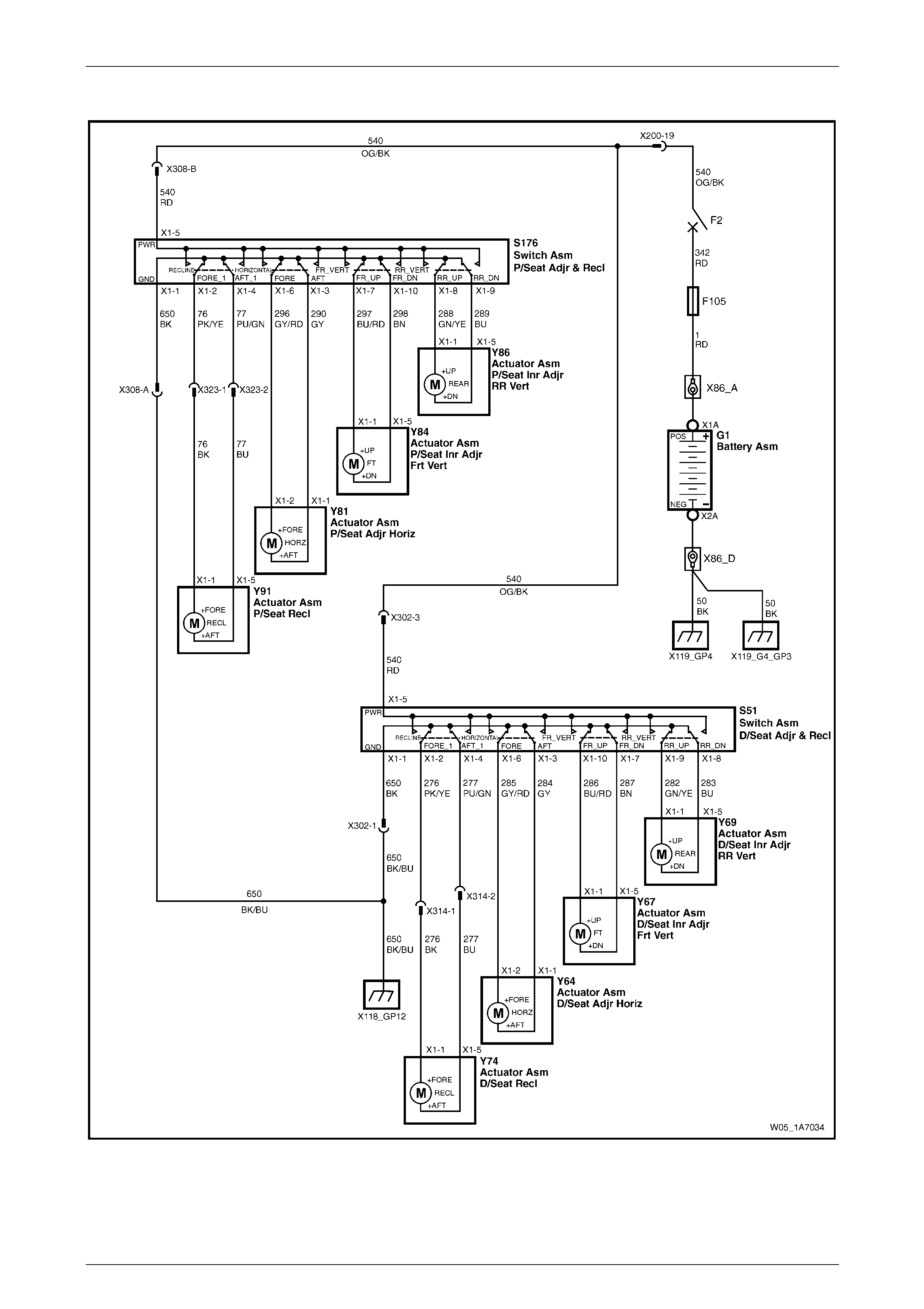
Seat Assemblies Page 1A7A–44
Page 1A7A–44
Wiring Diagram – Eight-way Seat, Non-memory, RHD
Figure 1A7A – 10
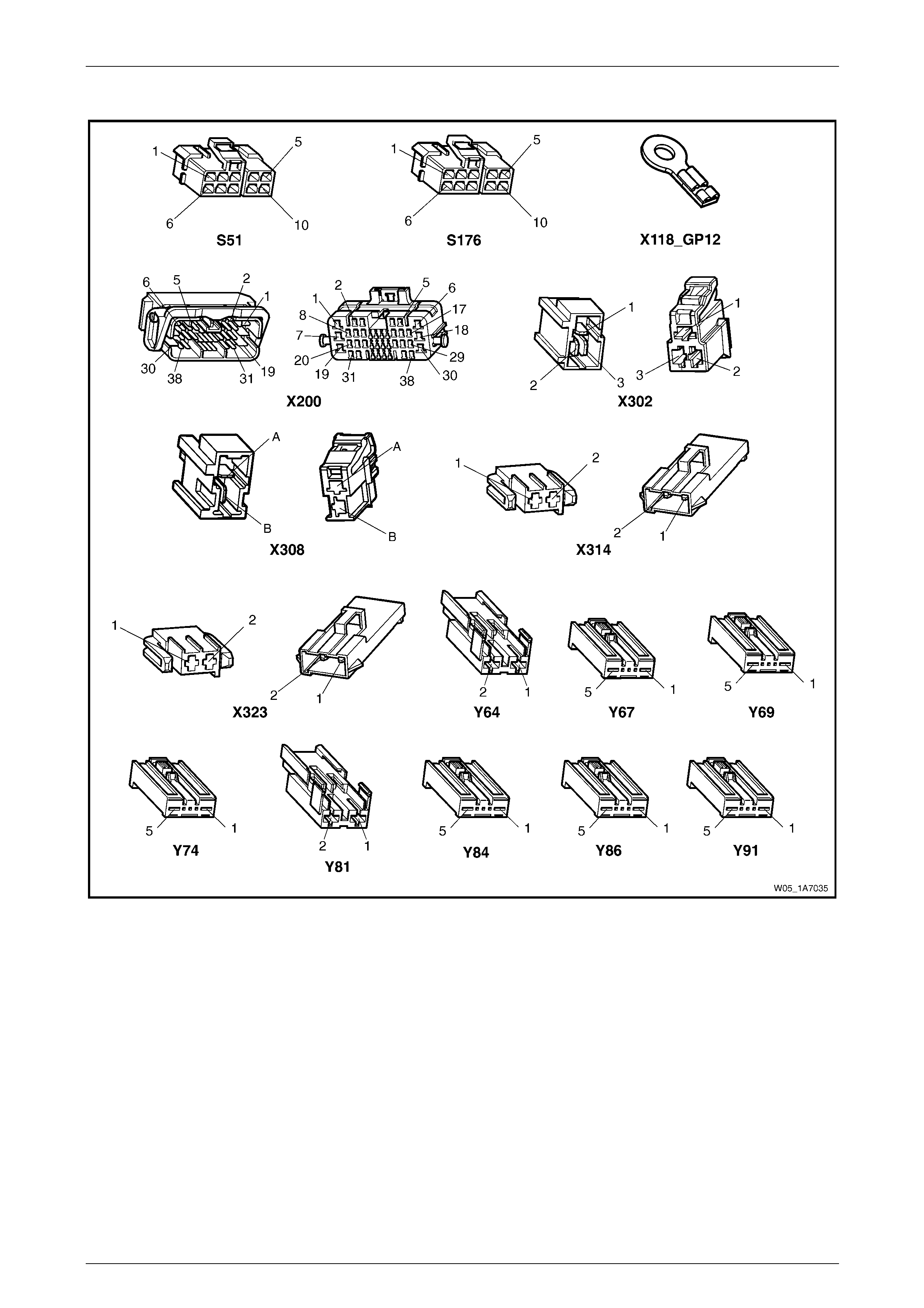
Seat Assemblies Page 1A7A–45
Page 1A7A–45
Connector Chart – Eight-way Seat, Non-memory, RHD
Figure 1A7A – 11

Seat Assemblies Page 1A7A–46
Page 1A7A–46
Neither Seat Adjustment Switch Functions Operate
Introduction
This test is used to aid in diagnosing the seat power and ground circuits, if neither seat operates when either seat
adjustment switch is operated.
Test Description
The following numbers refer to the step numbers in the diagnostic table:
1 Checks if battery voltage is more than 11.5 V. The seat motors require mo re than 11.5 V to operate correctly.
2 Checks if circuit breaker F2 located on the passenger com partment fuse and relay panel assembl y is tripped.
Isolates if circuit breaker F2 is the fault affecting the circuit between the battery and conne ctor X200 pin 19.
3 Checks if fusible link F105 located on the engine compartment fuse and relay panel assembly is serviceable.
Isolates if the fusible link is the fault affecting the circuit between the battery and connector X200 pin 19.
4 Checks if connector X200 is secure.
5 Checks if there is battery voltage at connector X200 pin 19. Isolates if the fault is between the battery and
connector X200 pin 19. If the fault in the circuit is between connectors X200 pin 19 and either X3 02 pin 3 or
X308 pin B, only o ne seat will operate.
6 Checks if there is battery voltage at circuit breaker F2. Isolates whether the fault is between the b attery and circuit
breaker F2 or bet ween circuit breaker F2 an d connector X200 pin 19.
7 Checks if there is battery voltage at fusible link F105. Isolates whether the fault is between the battery and fusible
link F105 or between fusible li nk F 105 and circuit breaker F2.
8 Checks if the ground point associated with the system is serviceable.
Diagnostic Table Notes
1 For all wiring harness fault diagnoses, refer to Section 12P Wiring Diagram s.
2 For wiring harness repairs, refer to Section 12P Wiring Diagrams.
3 Refer to Section 12O Fuses, Relays and Wiring Harnesses for harness routeing.
4 If the fault is deemed to be intermittent, refer to Section 12P Wiring Diagrams.

Seat Assemblies Page 1A7A–47
Page 1A7A–47
Diagnostic Table
Step Action Yes No
1 Check the battery voltage, refer to Section 12A Battery.
Is the battery voltage more than 11.5 V? Go to Step 2
Refer to Section
12A Battery for
further diagnosis
2 Inspect circuit breaker F2, refer to Section 12O Fuses, Relays and
Wiring Harnesses.
Is circuit breaker F2 tripped?
Allow the circuit
breaker to reset
(refer to Note 3).
If the circuit breaker
trips again, repair or
replace circuit 540
(refer to Note 2) Go to Step 3
3 Inspect fusible link F105, refer to Section 12O Fuses, Relays and
Wiring Harnesses.
Is fuse F105 serviceable?
Go to Step 4
Replace the fusible
link.
If the fusible link
becomes
unserviceable
again, repair or
replace circuit 342
(refer to Note 2)
4 Is connector X200 secure (refer to Note 3)? Go to Step 5 Ensure the
connector is secure
5 Backprobe connector X200 pin 19 with a test lamp (refer to Note 1).
Does the test lamp illuminate? Go to Step 8 Go to Step 6
6 1 Remove circuit breaker F2 from the passenger compartment
fuse and relay panel assembly.
2 Using a test lamp, probe connector X12 9 – X45 pin – 2 (refer to
Note 1).
Does the test lamp illuminate?
Repair or replace
circuit 540 between
circuit breaker F2
and connector
X200 pin 19 (refer to
Note 2) Go to Step 7
7 1 Remove fusible link F105.
2 Using a test lamp, probe connector X18-105 (refer to Note 1).
Does the test lamp illuminate?
Repair or replace
circuit 342 between
fusible link F105
and circuit breaker
F2 (refer to Note 2)
Repair or replace
circuit 1 between
the battery and
fusible link F105
(refer to Note 2)
8 Ensure ground point X118 – GP12 (located in the middle of the
transmission tunnel) is secure and has good contact with the vehicle
structure.
Is the ground point secure to the vehicle with a good contact?
Repair or replace
circuit 650 (refer to
Note 2) Repair ground point
When all diagno sis and repairs are completed, ch eck the system for correct operation.

Seat Assemblies Page 1A7A–48
Page 1A7A–48
None of the Driver’s Seat Adjustment Switch Functions Operate
Introduction
This test is used to aid in diagnosing the driver’s seat adjustment switch when none of the switch functions operate. The
test diagnoses the driver’s seat adjustment switch and associated power and ground circuits.
Test Description
The following numbers refer to the step numbers in the diagnostic table:
1 Checks if all of the passenger seat functions work. If none of them work, the fault is not isolated to the driver’s seat.
2 Checks if there is battery power at connector X302 pi n 3. Isolates if there i s a fault in circuit 540 between
connectors X200 pin 19 and X302 pin 3.
3 Checks if all the connectors required for the seat to operate effectively are in place a nd positively connected.
4 Checks if there is battery power at connector S51 – X1 pi n 5. Isolates if there is a fault in circuit 540 between
connectors S51 – X1 pin 5 and X302 p in 3.
5 Checks if the driver’s seat adjustment switch is serviceable.
6 Checks if there is continuity between connectors S51 – X1 pin 1 and X302 pin 1 which supplies the ground circuit
for the driver’s seat adjustment switch. Isolates whether there is a fault in circuit 650 between the switch and
connector X302 pin 1 or between connector X302 pin 1 and the ground point.
Diagnostic Table Notes
1 For all wiring harness fault diagnoses, refer to Section 12P Wiring Diagram s.
2 For wiring harness repairs, refer to Section 12P Wiring Diagrams.
3 Refer to Section 12O Fuses, Relays and Wiring Harnesses for harness routeing.
4 If the fault is deemed to be intermittent, refer to Section 12P Wiring Diagrams.

Seat Assemblies Page 1A7A–49
Page 1A7A–49
Diagnostic Table
Step Action Yes No
1 Are all of the passenger’s seat adjustment switch functions
inoperative? Refer to Neither
Seat Adjustment
Switch Functions
Operate in this
Section Go to Step 2
2 Backprobe connector X302 pin 3 with a test lamp (refer to Note 1).
Does the test lamp illuminate?
Go to Step 3
Repair or replace
circuit 540 between
connectors
X200 pin 19 an d
X302 pin 3 (refer to
Note 2)
3 Are the following connectors secure (refer to Note 3)?
• S51
• X302
• Y64
• Y67
• Y69
• Y74 Go to Step 4
Ensure the
connectors are
secure
4 Backprobe connector S51 – X1 pin 5 with a test lamp (refer to Note 1).
Does the test lamp illuminate?
Go to Step 5
Repair or replace
circuit 540 between
connectors
S51 – X1 pin 5 and
X302 pin 3 (refer to
Note 2)
5 1 Remove the driver’s seat adjustment switch from the seat, refer
to 5.4 Front Seat Outer Side Cover Assembly.
2 Test the driver’s seat adjustment switch, refer to 3.5 Eight-way
Seat Adjustment Switch Test.
Is the driver’s seat adjustment switch serviceable? Go to Step 6
Replace the driver’s
seat adjustment
switch, refer to 5.4
Front Seat Outer
Side Cover
Assembly
6 1 Backprobe connector X30 2 pin 1 with a test lamp (refer to Note
1).
2 Operate the driver’s seat adjustment switch in any of the
available directions.
Does the test lamp illuminate?
Repair or replace
circuit 650 between
connector X302 pin
1 and ground point
X118 – GP12 (refer
to Note 2)
Repair or replace
circuit 650 between
connectors
S51 – X1 pin 1 and
X302 pin 1 (refer to
Note 2)
When all diagno sis and repairs are completed, ch eck the system for correct operation.

Seat Assemblies Page 1A7A–50
Page 1A7A–50
Front/Rear of the Driver’s Seat Does Not Raise and/or Lower
Introduction
This test is used to aid in diagnosing the front and/or the rear of the driver’s seat not raising and/or lowering. T he test
diagnoses the seat adjustmen t switch and the motor circuits.
Test Description
The following numbers refer to the step numbers in the diagnostic table:
1 Checks if the driver’s seat adjustment switch operates the seat in any direction. Isolates if the power and ground
circuits are at fault.
2 Checks if all the connectors required for the seat to operate effectively are in place a nd positively connected.
3 Checks if the driver’s seat adjustment switch is serviceable.
4 Confirms whether the rear of the seat raises or lowers. Isolates if the seat rear lift motor and circuit of the seat is the
fault.
5 Confirms whether the front of the seat raises or lo wers. Isolates if the seat front lift motor and circuit of the seat is
the fault.
6 Checks if there is battery power to the seat rear lift motor at connector Y69 – X1 pin 1. Isolates if there is a fault in
circuit 282 that supplies battery po wer to the motor to raise the rear of the seat.
7 Checks if there is battery power to the seat rear lift motor at connector Y69 – X1 pin 5. Isolates whether the fault is
in circuit 283 that supplies battery power to the motor to lower the rear of the seat or the motor is faulty. As the
direction of the motor is changed by reversing the polarity, this Step also confirms if the ground circuit from Step 6
is serviceable.
8 Checks if there is battery power to the seat front lift motor at connector Y67 – X1 pin 1. Isolates if there is a fault in
circuit 286 that supplies battery po wer to the motor to raise the front of the seat.
9 Checks if there is battery power to the seat front lift motor at connector Y67 – X1 pin 5. Isolates whether the fault is
in circuit 287 that supplies battery power to the motor to lower the front of the seat or the motor is faulty. As the
direction of the motor is changed by reversing the polarity, this Step also confirms if the ground circuit from Step 8
is serviceable.
Diagnostic Table Notes
1 For all wiring harness fault diagnoses, refer to Section 12P Wiring Diagram s.
2 For wiring harness repairs, refer to Section 12P Wiring Diagrams.
3 Refer to Section 12O Fuses, Relays and Wiring Harnesses for harness routeing.
4 If the fault is deemed to be intermittent, refer to Section 12P Wiring Diagrams.

Seat Assemblies Page 1A7A–51
Page 1A7A–51
Diagnostic Table
Step Action Yes No
1 Does the driver’s seat adjustment switch operate the seat correctly in
any of the eight directions?
Go to Step 2
Refer to None of the
Driver’s Seat
Adjustment Switch
Functions Operate
in this Section
2 Are the following connectors secure (refer to Note 3)?
• S51
• Y67
• Y69 Go to Step 3
Ensure the
connectors are
secure
3 1 Remove the driver’s seat adjustment switch from the seat, refer
to 5.4 Front Seat Outer Side Cover Assembly.
2 Test the driver’s seat adjustment switch, refer to 3.5 Eight-way
Seat Adjustment Switch Test.
Is the driver’s seat adjustment switch serviceable? Go to Step 4
Replace the driver’s
seat adjustment
switch, refer to 5.4
Front Seat Outer
Side Cover
Assembly
4 Operate the driver’s seat adjustment switch to raise or lower the rear
of the seat.
Does the rear of the seat raise and lo wer? Go to Step 5 Go to Step 6
5 Operate the driver’s seat adjustment switch to raise or lower the front
of the seat.
Does the front of the seat raise and lower? System serviceable Go to Step 8
6 1 Backprobe connector Y69 – X1 pin 1 with a test lamp (refer to
Note 1).
2 Operate the driver’s seat adjustment switch to raise the rear of
the seat.
Does the test lamp illuminate? Go to Step 7
Repair or replace
circuit 282 (refer to
Note 2)
7 1 Backprobe connector Y69 – X1 pin 5 with a test lamp (refer to
Note 1).
2 Operate the driver’s seat adjustment switch to lower the rear of
the seat.
Does the test lamp illuminate?
Replace the seat
rear lift motor, refer
to 5.16 Front Seat
Lift Motor
Assemblies
Repair or replace
circuit 283 (refer to
Note 2)
8 1 Backprobe connector Y67 – X1 pin 1 with a test lamp (refer to
Note 1).
2 Operate the driver’s seat adjustment switch to raise the front of
the seat.
Does the test lamp illuminate? Go to Step 9
Repair or replace
circuit 286 (refer to
Note 2)
9 1 Backprobe connector Y67 – X1 pin 5 with a test lamp (refer to
Note 1).
2 Operate the driver’s seat adjustment switch to lower the front of
the seat.
Does the test lamp illuminate?
Replace the seat
front lift motor, refer
to 5.16 Front Seat
Lift Motor
Assemblies
Repair or replace
circuit 287 (refer to
Note 2)
When all diagno sis and repairs are completed, ch eck the system for correct operation.

Seat Assemblies Page 1A7A–52
Page 1A7A–52
Driver’s Seat Fore/Aft Movement Function is Inoperative or Not Smooth
Introduction
This test is used to aid in diagnosi ng the fore/aft movement function of the driver’s seat being inoperative or the action of
the seat through the range of movement is not smooth. The test diagnoses the seat adjustment switch and the motor
circuits.
Test Description
The following numbers refer to the step numbers in the diagnostic table:
1 Checks if the driver’s seat adjustment switch operates the seat in any direct ion. Isolates if there is battery power to
the switch assembly.
2 Checks if there are any items obstructing the guide rails, which may stop or hinder the seat movement.
3 Checks if the guide rails and drive shafts have adequate lubricant applied t o provide a smooth operation of the
seat.
4 Checks if the guide rails or drive shafts have been damaged. An y binding between the moving parts will result in
poor operation of the fore and aft movement.
5 Checks if all the connectors required for the seat to operate effectively are in place a nd positively connected.
6 Checks if the driver’s seat adjustment switch is serviceable.
7 Checks if there is battery power to the seat fore/aft movement motor at connector Y64 – X1 pin 2. Isolates if there
is a fault in circuit 285 that supplies battery power to the motor to move the seat forward.
8 Checks if there is battery power to the seat fore/aft movement motor at connector Y64 – X1 pin 1. Isolates whether
the fault is in circuit 284 that supplies battery power to the motor to move the seat aft or the motor is faulty. As
reversing the polarity changes the direction of the motor, this Step also confirms if the ground circuit from Step 7 is
serviceable.
Diagnostic Table Notes
1 For all wiring harness fault diagnoses, refer to Section 12P Wiring Diagram s.
2 For wiring harness repairs, refer to Section 12P Wiring Diagrams.
3 Refer to Section 12O Fuses, Relays and Wiring Harnesses for harness routeing.
4 If the fault is deemed to be intermittent, refer to Section 12P Wiring Diagrams.

Seat Assemblies Page 1A7A–53
Page 1A7A–53
Diagnostic Table
Step Action Yes No
1 Does the driver’s seat adjustment switch operate the seat correctly in
any of the eight directions?
Go to Step 2
Refer to None of the
Driver’s Seat
Adjustment Switch
Functions Operate
in this Section
2 Are the guide rails free from obstructions? Go to Step 3 Remove the
obstructing item
3 Are the guide rails and driv e shafts adequately lubricated?
Go to Step 4
Apply a small
amount of grease
type NLGI No. 1
Lithium Grease
(with 9% Zinc
Oxide)
4 Do the guide rails or drive shafts bind at any point of travel during the
fore and aft movement of the seat? Replace the track
and height adjust
assembly, refer to
5.13 Track and
Height Adjust
Assembly Go to Step 5
5 Are the following connectors secure (refer to Note 3)?
• S51
• Y64 Go to Step 6
Ensure the
connectors are
secure
6 1 Remove the driver’s seat adjustment switch from the seat, refer
to 5.4 Front Seat Outer Side Cover Assembly.
2 Test the driver’s seat adjustment switch, refer to 3.5 Eight-way
Seat Adjustment Switch Test.
Is the driver’s seat adjustment switch serviceable? Go to Step 7
Replace the driver’s
seat adjustment
switch, refer to 5.4
Front Seat Outer
Side Cover
Assembly
7 1 Backprobe connector Y64 – X1 pin 2 with a test lamp (refer to
Note 1).
2 Operate the driver’s seat adjustment switch to move the seat
forward.
Does the test lamp illuminate? Go to Step 8
Repair or replace
circuit 285 (refer to
Note 2)
8 1 Backprobe connector Y64 – X1 pin 1 with a test lamp (refer to
Note 1).
2 Operate the driver’s seat adjustment switch to move the seat aft.
Does the test lamp illuminate?
Replace the seat
fore/aft movement
motor, refer to 5.17
Front Seat Fore/Aft
Movement Motor
Assembly
Repair or replace
circuit 284 (refer to
Note 2)
When all diagno sis and repairs are completed, ch eck the system for correct operation.

Seat Assemblies Page 1A7A–54
Page 1A7A–54
Driver’s Seat-back Recline Forward and/or Aft Function is Inoperative
Introduction
This test is used to aid in diagnosing the recline function of the driver’s seat being inoperative. The test diagnoses the
seat adjustment switch and the motor circuits.
Test Description
The following numbers refer to the step numbers in the diagnostic table:
1 Checks if the driver’s seat adjustment switch operates the seat in any direct ion. Isolates if there is battery power to
the switch assembly.
2 Checks if all the connectors required for the seat to operate effectively are in place a nd positively connected.
3 Checks if the driver’s seat adjustment switch is serviceable.
4 Checks if there is battery power to the seat-back recline motor at connect or Y74 – X1 pin 1. Isolates if there is a
fault in circuit 276 that supplies battery power to the motor to move the seat-back forward.
5 Isolates whether there is a fault in circuit 276 between connectors S51 – X1 pin 2 and X314 pin 1 or between
connectors X314 pin 1 and Y74 – X1 pin 1.
6 Checks if there is battery power to the seat-back recline motor at connector Y74 – X1 pi n 5. Isolates whether the
fault is in circuit 277 that supplies battery power to the motor to move the seat-back aft or the motor is faulty. As
reversing the polarity changes the direction of the motor, this Step also confirms if the ground circuit from Step 4 is
serviceable.
7 Isolates whether there is a fault in circuit 277 between connectors S51 – X1 pin 4 and X314 pin 2 or between
connectors X314 pin 2 and Y74 – X1 pin 5.
Diagnostic Table Notes
1 For all wiring harness fault diagnoses, refer to Section 12P Wiring Diagram s.
2 For wiring harness repairs, refer to Section 12P Wiring Diagrams.
3 Refer to Section 12O Fuses, Relays and Wiring Harnesses for harness routeing.
4 If the fault is deemed to be intermittent, refer to Section 12P Wiring Diagrams.

Seat Assemblies Page 1A7A–55
Page 1A7A–55
Diagnostic Table
Step Action Yes No
1 Does the driver’s seat adjustment switch operate the seat correctly in
any of the eight directions?
Go to Step 2
Refer to None of the
Driver’s Seat
Adjustment Switch
Functions Operate
in this Section
2 Are the following connectors secure (refer to Note 3)?
• S51
• Y74 Go to Step 3
Ensure the
connectors are
secure
3 1 Remove the driver’s seat adjustment switch from the seat, refer
to 5.4 Front Seat Outer Side Cover Assembly.
2 Test the driver’s seat adjustment switch, refer to 3.5 Eight-way
Seat Adjustment Switch Test.
Is the driver’s seat adjustment switch serviceable? Go to Step 4
Replace the driver’s
seat adjustment
switch, refer to 5.4
Front Seat Outer
Side Cover
Assembly
4 1 Backprobe connector Y74 – X1 pin 1 with a test lamp (refer to
Note 1).
2 Operate the driver’s seat adjustment switch to move the
seat-back forward.
Does the test lamp illuminate? Go to Step 6 Go to Step 5
5 1 Backprobe connector X31 4 pin 1 with a test lamp (refer to Note
1).
2 Operate the passenger’s seat adjustment switch to move the
seat-back forward.
Does the test lamp illuminate?
Repair or replace
circuit 276 between
connectors
X314 pin 1 and
Y74 – X1 pin 1
(refer to Note 2)
Repair or replace
circuit 276 between
connectors
S51 – X1 pin 2 and
X314 pin 1 (refer to
Note 2)
6 1 Backprobe connector Y74 – X1 pin 5 with a test lamp (refer to
Note 1).
2 Operate the driver’s seat adjustment switch to move the
seat-back aft.
Does the test lamp illuminate?
Replace the
seat-back recline
motor, refer to 5.18
Front Seat-back
Recline Motor
Assembly Go to Step 7
7 1 Backprobe connector X31 4 pin 2 with a test lamp (refer to Note
1).
2 Operate the passenger’s seat adjustment switch to move the
seat-back aft.
Does the test lamp illuminate?
Repair or replace
circuit 277 between
connectors
X314 pin 2 and
Y74 – X1 pin 5
(refer to Note 2)
Repair or replace
circuit 277 between
connectors
S51 – X1 pin 4 and
X314 pin 2 (refer to
Note 2)
When all diagno sis and repairs are completed, ch eck the system for correct operation.

Seat Assemblies Page 1A7A–56
Page 1A7A–56
None of the Passenger’s Seat Adjustment Switch Functions Operate
Introduction
This test is used to aid in diagnosing the passenger’s seat adjustment switch when none of the switch functions operate.
The test diagnoses the passenger’s seat adjustment switch and associated power and ground circuits.
Test Description
The following numbers refer to the step numbers in the diagnostic table:
1 Checks if all of the driver’s seat functions work. If none of them work, the fault is not isolated to the passenger’s
seat.
2 Checks if there is battery power at connector X308 pin B. Isolates if there is a fault in circuit 540 between
connectors X200 pin 19 and X308 pin B.
3 Checks if all the connectors required for the seat to operate effectively are in place a nd positively connected.
4 Checks if there is battery power at connector S176 – X1 pin 5. Isolates if there is a fault in circuit 540 between
connectors S176 – X1 pin 5 and X308 pin B.
5 Checks if the passenger’s seat adjustment switch is serviceable.
6 Checks if there is continuity between connec tors S176 – X1 pin 1 and X308 pin A which supp lies the ground circuit
for the passenger’s seat adjustment s witch. Isolates whether there is a fault in circuit 650 between the switch and
connector X308 pin A or between connector X308 pin A and the ground point.
Diagnostic Table Notes
1 For all wiring harness fault diagnoses, refer to Section 12P Wiring Diagram s.
2 For wiring harness repairs, refer to Section 12P Wiring Diagrams.
3 Refer to Section 12O Fuses, Relays and Wiring Harnesses for harness routeing.
4 If the fault is deemed to be intermittent, refer to Section 12P Wiring Diagrams.

Seat Assemblies Page 1A7A–57
Page 1A7A–57
Diagnostic Table
Step Action Yes No
1 Are all of the driver’s seat adjustment switch functions inoper ative? Refer to Neither
Seat Adjustment
Switch Functions
Operate in this
Section Go to Step 2
2 Backprobe connector X308 pin B with a test lamp (refer to Note 1).
Does the test lamp illuminate?
Go to Step 3
Repair or replace
circuit 540 between
connectors X200 pin
19 and X308 pin B
(refer to Note 2)
3 Are the following connectors secure (refer to Note 3)?
• S176
• X308
• Y81
• Y84
• Y86
• Y91 Go to Step 4
Ensure the
connectors are
secure
4 Backprobe connector S176 – X1 pin 5 with a test lamp (refer to Note
1).
Does the test lamp illuminate?
Go to Step 5
Repair or replace
circuit 540 between
connectors
S176 – X1 pin 5 and
X308 pin B (refer to
Note 2)
5 1 Remove the passenger’s seat adjustment switch from the seat,
refer to 5.4 Front Seat Outer Side Cover Assembly.
2 Test the passenger’s seat adjustment switch, refer to 3.5 Eight-
way Seat Adjustment Switch Test.
Is the passenger’s seat adjustment s witch serviceable? Go to Step 6
Replace the
passenger’s seat
adjustment switch,
refer to 5.4 Front
Seat Outer Side
Cover Assembly
6 1 Backprobe connector X30 8 pin A with a test lamp (refer to Note
1).
2 Operate the passenger’s seat adjustment switch in any of the
available directions.
Does the test lamp illuminate?
Repair or replace
circuit 650 between
connector X308 pin
A and ground point
X118 – GP12 (refer
to Note 2)
Repair or replace
circuit 650 between
connectors
S176 – X1 pin 1 and
X308 pin A (refer to
Note 2)
When all diagno sis and repairs are completed, ch eck the system for correct operation.

Seat Assemblies Page 1A7A–58
Page 1A7A–58
Front/Rear of the Passenger’s Seat Does Not Raise and/or Lower
Introduction
This test is used to aid in diagnosing the front and/or the rear of the passenger’s seat not raising and/or lowering. The
test diagnoses the seat adjustment switch and the motor circuits.
Test Description
The following numbers refer to the step numbers in the diagnostic table:
1 Checks if the passenger’s seat adjustment switch operates the seat in any direction. Isolates whether the power
and/or ground circuits are at fault.
2 Checks if all the connectors required for the seat to operate effectively are in place a nd positively connected.
3 Checks if the passenger’s seat adjustment switch is serviceable.
4 Confirms whether the rear of the seat raises or lowers. Isolates if the rear lift motor and circuit of the seat is the
fault.
5 Confirms whether the front of the seat raises or lo wers. Isolates if the front lift motor and circuit of the seat is the
fault.
6 Checks if there is battery power to the seat rear lift motor at connector Y86 – X1 pin 1. Isolates if there is a fault in
circuit 288 that supplies battery po wer to the motor to raise the rear of the seat.
7 Checks if there is battery power to the seat rear lift motor at connector Y86 – X1 pin 5. Isolates whether the fault is
in circuit 289 that supplies battery power to the motor to lower the rear of the seat or the motor is faulty. As the
direction of the motor is changed by reversing the polarity, this Step also confirms if the ground circuit from Step 6
is serviceable.
8 Checks if there is battery power to the seat front lift motor at connector Y84 – X1 pin 1. Isolates if there is a fault in
circuit 297 that supplies battery po wer to the motor to raise the front of the seat.
9 Checks if there is battery power to the seat front lift motor at connector Y84 – X1 pin 5. Isolates whether the fault is
in circuit 298 that supplies battery power to the motor to lower the front of the seat or the motor is faulty. As the
direction of the motor is changed by reversing the polarity, this Step also confirms if the ground circuit from Step 8
is serviceable.
Diagnostic Table Notes
1 For all wiring harness fault diagnoses, refer to Section 12P Wiring Diagram s.
2 For wiring harness repairs, refer to Section 12P Wiring Diagrams.
3 Refer to Section 12O Fuses, Relays and Wiring Harnesses for harness routeing.
4 If the fault is deemed to be intermittent, refer to Section 12P Wiring Diagrams.

Seat Assemblies Page 1A7A–59
Page 1A7A–59
Diagnostic Table
Step Action Yes No
1 Does the passenger’s seat adjustment switch oper ate the seat
correctly in any of the eight directions?
Go to Step 2
Refer to None of the
Passenger’s Seat
Adjustment Switch
Functions Operate
in this Section
2 Are the following connectors secure (refer to Note 3)?
• S176
• Y84
• Y86 Go to Step 3
Ensure the
connectors are
secure
3 1 Remove the passenger’s seat adjustment switch from the seat,
refer to 5.4 Front Seat Outer Side Cover Assembly.
2 Test the passenger’s seat adjustment switch, refer to 3.5 Eight-
way Seat Adjustment Switch Test.
Is the passenger’s seat adjustment s witch serviceable? Go to Step 4
Replace the
passenger’s seat
adjustment switch,
refer to 5.4 Front
Seat Outer Side
Cover Assembly
4 Operate the passenger’s seat adj ustment switch to raise or lower the
rear of the seat.
Does the rear of the seat raise and lo wer? Go to Step 5 Go to Step 6
5 Operate the passenger’s seat adj ustment switch to raise or lower the
front of the seat.
Does the front of the seat raise and lower? System serviceable Go to Step 8
6 1 Backprobe connector Y86 – X1 pin 1 with a test lamp (refer to
Note 1).
2 Operate the passenger’s seat adjustment switch to raise the rear
of the seat.
Does the test lamp illuminate? Go to Step 7
Repair or replace
circuit 288 (refer to
Note 2)
7 1 Backprobe connector Y86 – X1 pin 5 with a test lamp (refer to
Note 1).
2 Operate the passenger’s seat adjustment switch to lower the
rear of the seat.
Does the test lamp illuminate?
Replace the seat
rear lift motor, refer
to 5.16 Front Seat
Lift Motor
Assemblies
Repair or replace
circuit 289 (refer to
Note 2)
8 1 Backprobe connector Y84 – X1 pin 1 with a test lamp (refer to
Note 1).
2 Operate the passenger’s seat adjustment switch to raise the
front of the seat.
Does the test lamp illuminate? Go to Step 9
Repair or replace
circuit 297 (refer to
Note 2)
9 1 Backprobe connector Y84 – X1 pin 5 with a test lamp (refer to
Note 1).
2 Operate the passenger’s seat adjustment switch to lower the
front of the seat.
Does the test lamp illuminate?
Replace the seat
front lift motor, refer
to 5.16 Front Seat
Lift Motor
Assemblies
Repair or replace
circuit 298 (refer to
Note 2)
When all diagno sis and repairs are completed, ch eck the system for correct operation.

Seat Assemblies Page 1A7A–60
Page 1A7A–60
Passenger’s Seat Fore/Aft Movement Function is Inoperative or Not Smooth
Introduction
This test is used to aid in diagnosing the fore/aft movement function of the passenger’s seat being in operative or the
action of the seat through the range of movement is not smooth. The test diagnoses the seat adjustment switch and the
motor circuits.
Test Description
The following numbers refer to the step numbers in the diagnostic table:
1 Checks if the passenger’s seat adjustment switch operates the seat in any direction. Isolates if there is battery
power to the switch assembly.
2 Checks if there are any items obstructing the guide rails, which may stop or hinder the seat movement.
3 Checks if the guide rails and drive shafts have adequate lubricant applied t o provide a smooth operation of the
seat.
4 Checks if the guide rails or drive shafts have been damaged. An y binding between the moving parts will result in
poor operation of the fore and aft movement.
5 Checks if all the connectors required for the seat to operate effectively are in place a nd positively connected.
6 Checks if the passenger’s seat adjustment switch is serviceable.
7 Checks if there is battery power to the seat fore/aft movement motor at connector Y81 – X1 pin 2. Isolates if there
is a fault in circuit 296 that supplies battery power to the motor to move the seat forward.
8 Checks if there is battery power to the seat fore/aft movement motor at connector Y81 – X1 pin 1. Isolates whether
the fault is in circuit 290 that supplies battery power to the motor to move the seat aft or the motor is faulty. As
reversing the polarity changes the direction of the motor, this Step also confirms if the ground circuit from Step 7 is
serviceable.
Diagnostic Table Notes
1 For all wiring harness fault diagnoses, refer to Section 12P Wiring Diagram s.
2 For wiring harness repairs, refer to Section 12P Wiring Diagrams.
3 Refer to Section 12O Fuses, Relays and Wiring Harnesses for harness routeing.
4 If the fault is deemed to be intermittent, refer to Section 12P Wiring Diagrams.

Seat Assemblies Page 1A7A–61
Page 1A7A–61
Diagnostic Table
Step Action Yes No
1 Does the passenger’s seat adjustment switch oper ate the seat
correctly in any of the eight directions?
Go to Step 2
Refer to None of the
Passenger’s Seat
Adjustment Switch
Functions Operate
in this Section
2 Are the guide rails free from obstructions? Go to Step 3 Remove the
obstructing item
3 Are the guide rails and driv e shafts adequately lubricated?
Go to Step 4
Apply a small
amount of grease
type NLGI No. 1
Lithium Grease
(with 9% Zinc
Oxide)
4 Do the guide rails or drive shafts bind at any point of travel during the
fore and aft movement of the seat? Replace the track
and height adjust
assembly, refer to
5.13 Track and
Height Adjust
Assembly Go to Step 5
5 Are the following connectors secure (refer to Note 3)?
• S176
• Y81 Go to Step 6
Ensure the
connectors are
secure
6 1 Remove the passenger’s seat adjustment switch from the seat,
refer to 5.4 Front Seat Outer Side Cover Assembly.
2 Test the passenger’s seat adjustment switch, refer to 3.5 Eight-
way Seat Adjustment Switch Test.
Is the passenger’s seat adjustment s witch serviceable? Go to Step 7
Replace the
passenger’s seat
adjustment switch,
refer to 5.4 Front
Seat Outer Side
Cover Assembly
7 1 Backprobe connector Y81 – X1 pin 2 with a test lamp (refer to
Note 1).
2 Operate the passenger’s seat adjustment switch to move the
seat forward.
Does the test lamp illuminate? Go to Step 8
Repair or replace
circuit 296 (refer to
Note 2)
8 1 Backprobe connector Y81 – X1 pin 1 with a test lamp (refer to
Note 1).
2 Operate the passenger’s seat adjustment switch to move the
seat aft.
Does the test lamp illuminate?
Replace the seat
fore/aft movement
motor, refer to 5.17
Front Seat Fore/Aft
Movement Motor
Assembly
Repair or replace
circuit 290 (refer to
Note 2)
When all diagno sis and repairs are completed, ch eck the system for correct operation.

Seat Assemblies Page 1A7A–62
Page 1A7A–62
Passenger’s Seat-back Recline Forward and/or Aft Function is Inoperative
Introduction
This test is used to aid in diagnosing the recline function of the passenger’s seat being inoperative. T he test diagnoses
the seat adjustment switch and the motor circuits.
Test Description
The following numbers refer to the step numbers in the diagnostic table:
1 Checks if the passenger’s seat adjustment switch operates the seat in any direction. Isolates if there is battery
power to the switch assembly.
2 Checks if all the connectors required for the seat to operate effectively are in place a nd positively connected.
3 Checks if the passenger’s seat adjustment switch is serviceable.
4 Checks if there is battery power to the seat-back recline motor at connect or Y91 – X1 pin 1. Isolates if there is a
fault in circuit 76 that supplies battery power to the motor to move the seat-back forward.
5 Isolates whether there is a fault in circuit 76 between connectors S176 – X1 pin 2 and X323 pin 1 or between
connectors X323 pin 1 and Y91 – X1 pin 1.
6 Checks if there is battery power to the seat-back recline motor at connector Y91 – X1 pi n 5. Isolates whether the
fault is in circuit 77 that supplies battery power to the motor to move the seat-back aft or the motor is faulty. As
reversing the polarity changes the direction of the motor, this Step also confirms if the ground circuit from Step 4 is
serviceable.
7 Isolates whether there is a fault in circuit 77 between connectors S176 – X1 pin 4 and X323 pin 2 or between
connectors X323 pin 2 and Y91 – X1 pin 5.
Diagnostic Table Notes
1 For all wiring harness fault diagnoses, refer to Section 12P Wiring Diagram s.
2 For wiring harness repairs, refer to Section 12P Wiring Diagrams.
3 Refer to Section 12O Fuses, Relays and Wiring Harnesses for harness routeing.
4 If the fault is deemed to be intermittent, refer to Section 12P Wiring Diagrams.

Seat Assemblies Page 1A7A–63
Page 1A7A–63
Diagnostic Table
Step Action Yes No
1 Does the passenger’s seat adjustment switch oper ate the seat
correctly in any of the eight directions?
Go to Step 2
Refer to None of the
Passenger’s Seat
Adjustment Switch
Functions Operate
in this Section
2 Are the following connectors secure (refer to Note 3)?
• S176
• Y91 Go to Step 3
Ensure the
connectors are
secure
3 1 Remove the passenger’s seat adjustment switch from the seat,
refer to 5.4 Front Seat Outer Side Cover Assembly.
2 Test the passenger’s seat adjustment switch, refer to 3.5 Eight-
way Seat Adjustment Switch Test.
Is the passenger’s seat adjustment s witch serviceable? Go to Step 4
Replace the
passenger’s seat
adjustment switch,
refer to 5.4 Front
Seat Outer Side
Cover Assembly
4 1 Backprobe connector Y91 – X1 pin 1 with a test lamp (refer to
Note 1).
2 Operate the passenger’s seat adjustment switch to move the
seat-back forward.
Does the test lamp illuminate? Go to Step 6 Go to Step 5
5 1 Backprobe connector X32 3 pin 1 with a test lamp (refer to Note
1).
2 Operate the passenger’s seat adjustment switch to move the
seat-back forward.
Does the test lamp illuminate?
Repair or replace
circuit 76 between
connectors
X323 pin 1 and
Y91 – X1 pin 1
(refer to Note 2)
Repair or replace
circuit 76 between
connectors
S176 – X1 pin 2 and
X323 pin 1 (refer to
Note 2)
6 1 Backprobe connector Y91 – X1 pin 5 with a test lamp (refer to
Note 1).
2 Operate the passenger’s seat adjustment switch to move the
seat-back aft.
Does the test lamp illuminate?
Replace the front
seat-back recline
motor, refer to 5.18
Front Seat-back
Recline Motor
Assembly Go to Step 7
7 1 Backprobe connector X32 3 pin 2 with a test lamp (refer to Note
1).
2 Operate the passenger’s seat adjustment switch to move the
seat-back aft.
Does the test lamp illuminate?
Repair or replace
circuit 77 between
connectors
X323 pin 2 and
Y91 – X1 pin 5
(refer to Note 2)
Repair or replace
circuit 77 between
connectors
S176 – X1 pin 4 and
X323 pin 2 (refer to
Note 2)
When all diagno sis and repairs are completed, ch eck the system for correct operation.

Seat Assemblies Page 1A7A–64
Page 1A7A–64
3.4 Electrical Diagnosis – Eight-way Seat,
Non-memory, LHD
The charts in this Section are used to aid in diagnosing faul ts on eight-way non-memory seat assemblies. To aid in the
use of the diagnostic tables, refer to Wiring Diagram – Eight-way Seat, Non-memory, LHD and
Connector Chart – Eight- way Seat, Non-memory, LHD.

Seat Assemblies Page 1A7A–65
Page 1A7A–65
Wiring Diagram – Eight-way Seat, Non-memory, LHD
Figure 1A7A – 12
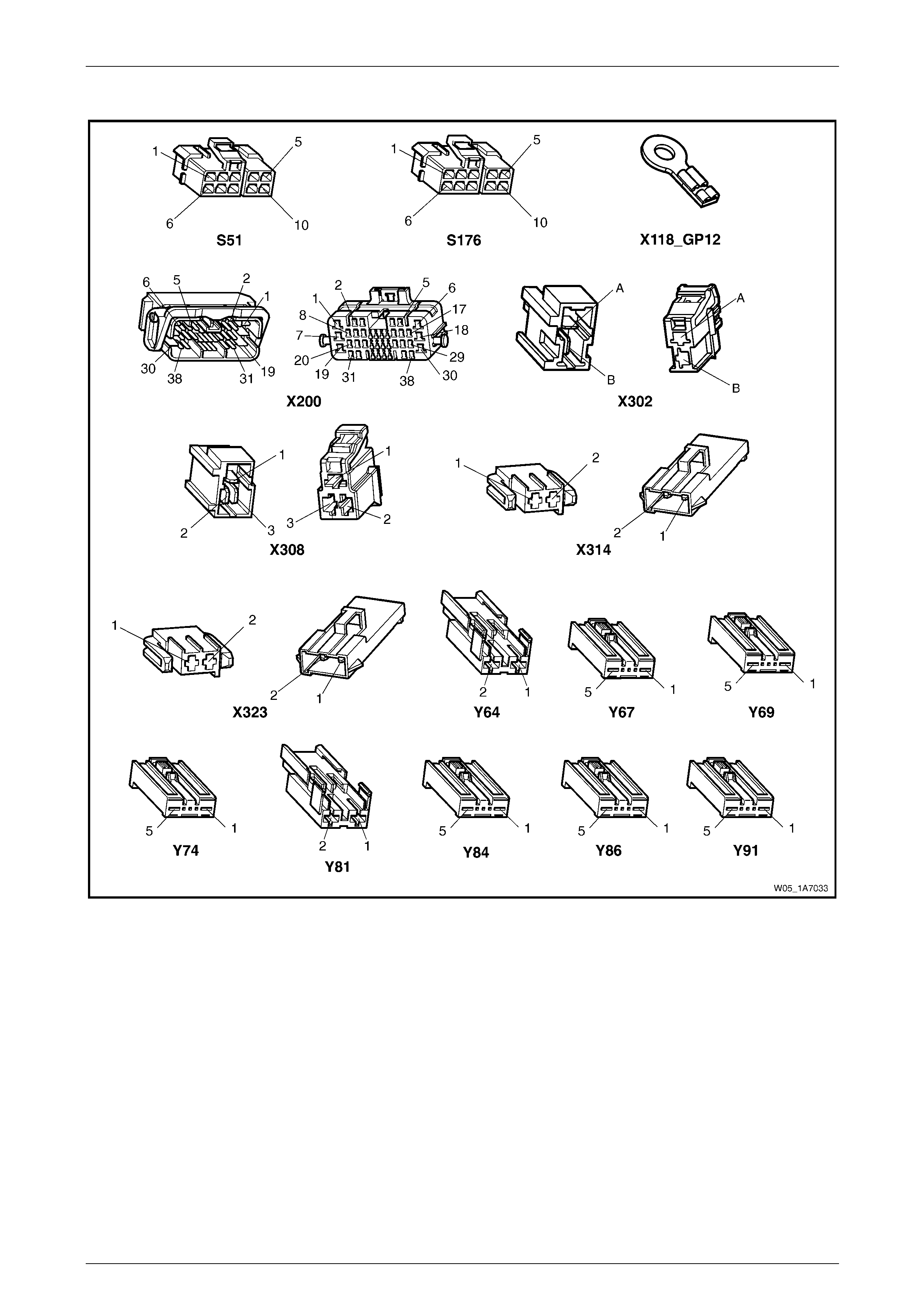
Seat Assemblies Page 1A7A–66
Page 1A7A–66
Connector Chart – Eight-way Seat, Non-memory, LHD
Figure 1A7A – 13

Seat Assemblies Page 1A7A–67
Page 1A7A–67
Neither Seat Adjustment Switch Functions Operate
Introduction
This test is used to aid in diagnosing the seat power and ground circuits, if neither seat operates when either seat
adjustment switch is operated.
Test Description
The following numbers refer to the step numbers in the diagnostic table:
1 Checks if battery voltage is more than 11.5 V. The seat motors require mo re than 11.5 V to operate correctly.
2 Checks if circuit breaker F2 located on the passenger com partment fuse and relay panel assembl y is tripped.
Isolates if circuit breaker F2 is the fault affecting the circuit between the battery and conne ctor X200 pin 19.
3 Checks if fusible link F105 located on the engine compartment fuse and relay panel assembly is serviceable.
Isolates if the fusible link is the fault affecting the circuit between the battery and connector X200 pin 19.
4 Checks if connector X200 is secure.
5 Checks if there is battery voltage at connector X200 pin 19. Isolates if the fault is between the battery and
connector X200 pin 19. If the fault in the circuit is between connectors X200 pin 19 and either X3 08 pin 3 or
X302 pin B, only o ne seat will operate.
6 Checks if there is battery voltage at circuit breaker F2. Isolates whether the fault is between the b attery and circuit
breaker F2 or bet ween circuit breaker F2 an d connector X200 pin 19.
7 Checks if there is battery voltage at fusible link F105. Isolates whether the fault is between the battery and fusible
link F105 or between fusible li nk F 105 and circuit breaker F2.
8 Checks if the ground point associated with the system is serviceable.
Diagnostic Table Notes
1 For all wiring harness fault diagnoses, refer to Section 12P Wiring Diagram s.
2 For wiring harness repairs, refer to Section 12P Wiring Diagrams.
3 Refer to Section 12O Fuses, Relays and Wiring Harnesses for harness routeing.
4 If the fault is deemed to be intermittent, refer to Section 12P Wiring Diagrams.

Seat Assemblies Page 1A7A–68
Page 1A7A–68
Diagnostic Table
Step Action Yes No
1 Check the battery voltage, refer to Section 12A Battery.
Is the battery voltage more than 11.5 V? Go to Step 2
Refer to Section
12A Battery for
further diagnosis
2 Inspect circuit breaker F2, refer to Section 12O Fuses, Relays and
Wiring Harnesses.
Is circuit breaker F2 tripped?
Allow the circuit
breaker to reset
(refer to Note 3).
If the circuit breaker
trips again, repair or
replace circuit 540
(refer to Note 2) Go to Step 3
3 Inspect fusible link F105, refer to Section 12O Fuses, Relays and
Wiring Harnesses.
Is fuse F105 serviceable?
Go to Step 4
Replace the fusible
link.
If the fusible link
becomes
unserviceable
again, repair or
replace circuit 342
(refer to Note 2)
4 Is connector X200 secure (refer to Note 3)? Go to Step 5 Ensure the
connector is secure
5 Backprobe connector X200 pin 19 with a test lamp (refer to Note 1).
Does the test lamp illuminate? Go to Step 8 Go to Step 6
6 1 Remove circuit breaker F2 from the passenger compartment
fuse and relay panel assembly.
2 Using a test lamp, probe connector X12 9 – X45 pin – 2 (refer to
Note 1).
Does the test lamp illuminate?
Repair or replace
circuit 540 between
circuit breaker F2
and connector
X200 pin 19 (refer to
Note 2) Go to Step 7
7 1 Remove fusible link F105.
2 Using a test lamp, probe connector X18-105 (refer to Note 1).
Does the test lamp illuminate?
Repair or replace
circuit 342 between
fusible link F105
and circuit breaker
F2 (refer to Note 2)
Repair or replace
circuit 1 between
the battery and
fusible link F105
(refer to Note 2)
8 Ensure ground point X118 – GP12 (located in the middle of the
transmission tunnel) is secure and has good contact with the vehicle
structure.
Is the ground point secure to the vehicle with a good contact?
Repair or replace
circuit 650 (refer to
Note 2) Repair ground point
When all diagno sis and repairs are completed, ch eck the system for correct operation.

Seat Assemblies Page 1A7A–69
Page 1A7A–69
None of the Driver’s Seat Adjustment Switch Functions Operate
Introduction
This test is used to aid in diagnosing the driver’s seat adjustment switch when none of the switch functions operate. The
test diagnoses the driver’s seat adjustment switch and associated power and ground circuits.
Test Description
The following numbers refer to the step numbers in the diagnostic table:
1 Checks if all of the passenger seat functions work. If none of them work, the fault is not isolated to the driver’s seat.
2 Checks if there is battery power at connector X308 pi n 3. Isolates if there i s a fault in circuit 540 between
connectors X200 pin 19 and X308 pin 3.
3 Checks if all the connectors required for the seat to operate effectively are in place a nd positively connected.
4 Checks if there is battery power at connector S51 – X1 pi n 5. Isolates if there is a fault in circuit 540 between
connectors S51 – X1 pin 5 and X308 p in 3.
5 Checks if the driver’s seat adjustment switch is serviceable.
6 Checks if there is continuity between connectors S51 – X1 pin 1 and X308 pin 1 which supplies the ground circuit
for the driver’s seat adjustment switch. Isolates whether there is a fault in circuit 650 between the switch and
connector X308 pin 1 or between connector X308 pin 1 and the ground point.
Diagnostic Table Notes
1 For all wiring harness fault diagnoses, refer to Section 12P Wiring Diagram s.
2 For wiring harness repairs, refer to Section 12P Wiring Diagrams.
3 Refer to Section 12O Fuses, Relays and Wiring Harnesses for harness routeing.
4 If the fault is deemed to be intermittent, refer to Section 12P Wiring Diagrams.

Seat Assemblies Page 1A7A–70
Page 1A7A–70
Diagnostic Table
Step Action Yes No
1 Are all of the passenger’s seat adjustment switch functions
inoperative? Refer to Neither
Seat Adjustment
Switch Functions
Operate in this
Section Go to Step 2
2 Backprobe connector X308 pin 3 with a test lamp (refer to Note 1).
Does the test lamp illuminate?
Go to Step 3
Repair or replace
circuit 540 between
connectors
X200 pin 19 an d
X308 pin 3 (refer to
Note 2)
3 Are the following connectors secure (refer to Note 3)?
• S51
• X308
• Y64
• Y67
• Y69
• Y74 Go to Step 4
Ensure the
connectors are
secure
4 Backprobe connector S51 – X1 pin 5 with a test lamp (refer to Note 1).
Does the test lamp illuminate?
Go to Step 5
Repair or replace
circuit 540 between
connectors
S51 – X1 pin 5 and
X308 pin 3 (refer to
Note 2)
5 1 Remove the driver’s seat adjustment switch from the seat, refer
to 5.4 Front Seat Outer Side Cover Assembly.
2 Test the driver’s seat adjustment switch, refer to 3.5 Eight-way
Seat Adjustment Switch Test.
Is the driver’s seat adjustment switch serviceable? Go to Step 6
Replace the driver’s
seat adjustment
switch, refer to 5.4
Front Seat Outer
Side Cover
Assembly
6 1 Backprobe connector X30 8 pin 1 with a test lamp (refer to Note
1).
2 Operate the driver’s seat adjustment switch in any of the
available directions.
Does the test lamp illuminate?
Repair or replace
circuit 650 between
connector X308 pin
1 and ground point
X118 – GP12 (refer
to Note 2)
Repair or replace
circuit 650 between
connectors
S51 – X1 pin 1 and
X308 pin 1 (refer to
Note 2)
When all diagno sis and repairs are completed, ch eck the system for correct operation.

Seat Assemblies Page 1A7A–71
Page 1A7A–71
Front/Rear of the Driver’s Seat Does Not Raise and/or Lower
Introduction
This test is used to aid in diagnosing the front and/or the rear of the driver’s seat not raising and/or lowering. T he test
diagnoses the seat adjustmen t switch and the motor circuits.
Test Description
The following numbers refer to the step numbers in the diagnostic table:
1 Checks if the driver’s seat adjustment switch operates the seat in any direction. Isolates if the power and ground
circuits are at fault.
2 Checks if all the connectors required for the seat to operate effectively are in place a nd positively connected.
3 Checks if the driver’s seat adjustment switch is serviceable.
4 Confirms whether the rear of the seat raises or lowers. Isolates if the seat rear lift motor and circuit of the seat is the
fault.
5 Confirms whether the front of the seat raises or lo wers. Isolates if the seat front lift motor and circuit of the seat is
the fault.
6 Checks if there is battery power to the seat rear lift motor at connector Y69 – X1 pin 1. Isolates if there is a fault in
circuit 282 that supplies battery po wer to the motor to raise the rear of the seat.
7 Checks if there is battery power to the seat rear lift motor at connector Y69 – X1 pin 5. Isolates whether the fault is
in circuit 283 that supplies battery power to the motor to lower the rear of the seat or the motor is faulty. As the
direction of the motor is changed by reversing the polarity, this Step also confirms if the ground circuit from Step 6
is serviceable.
8 Checks if there is battery power to the seat front lift motor at connector Y67 – X1 pin 1. Isolates if there is a fault in
circuit 286 that supplies battery po wer to the motor to raise the front of the seat.
9 Checks if there is battery power to the seat front lift motor at connector Y67 – X1 pin 5. Isolates whether the fault is
in circuit 287 that supplies battery power to the motor to lower the front of the seat or the motor is faulty. As the
direction of the motor is changed by reversing the polarity, this Step also confirms if the ground circuit from Step 8
is serviceable.
Diagnostic Table Notes
1 For all wiring harness fault diagnoses, refer to Section 12P Wiring Diagram s.
2 For wiring harness repairs, refer to Section 12P Wiring Diagrams.
3 Refer to Section 12O Fuses, Relays and Wiring Harnesses for harness routeing.
4 If the fault is deemed to be intermittent, refer to Section 12P Wiring Diagrams.

Seat Assemblies Page 1A7A–72
Page 1A7A–72
Diagnostic Table
Step Action Yes No
1 Does the driver’s seat adjustment switch operate the seat correctly in
any of the eight directions?
Go to Step 2
Refer to None of the
Driver’s Seat
Adjustment Switch
Functions Operate
in this Section
2 Are the following connectors secure (refer to Note 3)?
• S51
• Y67
• Y69 Go to Step 3
Ensure the
connectors are
secure
3 1 Remove the driver’s seat adjustment switch from the seat, refer
to 5.4 Front Seat Outer Side Cover Assembly.
2 Test the driver’s seat adjustment switch, refer to 3.5 Eight-way
Seat Adjustment Switch Test.
Is the driver’s seat adjustment switch serviceable? Go to Step 4
Replace the driver’s
seat adjustment
switch, refer to 5.4
Front Seat Outer
Side Cover
Assembly
4 Operate the driver’s seat adjustment switch to raise or lower the rear
of the seat.
Does the rear of the seat raise and lo wer? Go to Step 5 Go to Step 6
5 Operate the driver’s seat adjustment switch to raise or lower the front
of the seat.
Does the front of the seat raise and lower? System serviceable Go to Step 8
6 1 Backprobe connector Y69 – X1 pin 1 with a test lamp (refer to
Note 1).
2 Operate the driver’s seat adjustment switch to raise the rear of
the seat.
Does the test lamp illuminate? Go to Step 7
Repair or replace
circuit 282 (refer to
Note 2)
7 1 Backprobe connector Y69 – X1 pin 5 with a test lamp (refer to
Note 1).
2 Operate the driver’s seat adjustment switch to lower the rear of
the seat.
Does the test lamp illuminate?
Replace the seat
rear lift motor, refer
to 5.16 Front Seat
Lift Motor
Assemblies
Repair or replace
circuit 283 (refer to
Note 2)
8 1 Backprobe connector Y67 – X1 pin 1 with a test lamp (refer to
Note 1).
2 Operate the driver’s seat adjustment switch to raise the front of
the seat.
Does the test lamp illuminate? Go to Step 9
Repair or replace
circuit 286 (refer to
Note 2)
9 1 Backprobe connector Y67 – X1 pin 5 with a test lamp (refer to
Note 1).
2 Operate the driver’s seat adjustment switch to lower the front of
the seat.
Does the test lamp illuminate?
Replace the seat
front lift motor, refer
to 5.16 Front Seat
Lift Motor
Assemblies
Repair or replace
circuit 287 (refer to
Note 2)
When all diagno sis and repairs are completed, ch eck the system for correct operation.

Seat Assemblies Page 1A7A–73
Page 1A7A–73
Driver’s Seat Fore/Aft Movement Function is Inoperative or Not Smooth
Introduction
This test is used to aid in diagnosi ng the fore/aft movement function of the driver’s seat being inoperative or the action of
the seat through the range of movement is not smooth. The test diagnoses the seat adjustment switch and the motor
circuits.
Test Description
The following numbers refer to the step numbers in the diagnostic table:
1 Checks if the driver’s seat adjustment switch operates the seat in any direct ion. Isolates if there is battery power to
the switch assembly.
2 Checks if there are any items obstructing the guide rails, which may stop or hinder the seat movement.
3 Checks if the guide rails and drive shafts have adequate lubricant applied t o provide a smooth operation of the
seat.
4 Checks if the guide rails or drive shafts have been damaged. An y binding between the moving parts will result in
poor operation of the fore and aft movement.
5 Checks if all the connectors required for the seat to operate effectively are in place a nd positively connected.
6 Checks if the driver’s seat adjustment switch is serviceable.
7 Checks if there is battery power to the seat fore/aft movement motor at connector Y64 – X1 pin 2. Isolates if there
is a fault in circuit 285 that supplies battery power to the motor to move the seat forward.
8 Checks if there is battery power to the seat fore/aft movement motor at connector Y64 – X1 pin 1. Isolates whether
the fault is in circuit 284 that supplies battery power to the motor to move the seat aft or the motor is faulty. As
reversing the polarity changes the direction of the motor, this Step also confirms if the ground circuit from Step 7 is
serviceable.
Diagnostic Table Notes
1 For all wiring harness fault diagnoses, refer to Section 12P Wiring Diagram s.
2 For wiring harness repairs, refer to Section 12P Wiring Diagrams.
3 Refer to Section 12O Fuses, Relays and Wiring Harnesses for harness routeing.
4 If the fault is deemed to be intermittent, refer to Section 12P Wiring Diagrams.

Seat Assemblies Page 1A7A–74
Page 1A7A–74
Diagnostic Table
Step Action Yes No
1 Does the driver’s seat adjustment switch operate the seat correctly in
any of the eight directions?
Go to Step 2
Refer to None of the
Driver’s Seat
Adjustment Switch
Functions Operate
in this Section
2 Are the guide rails free from obstructions? Go to Step 3 Remove the
obstructing item
3 Are the guide rails and driv e shafts adequately lubricated?
Go to Step 4
Apply a small
amount of grease
type NLGI No. 1
Lithium Grease
(with 9% Zinc
Oxide)
4 Do the guide rails or drive shafts bind at any point of travel during the
fore and aft movement of the seat? Replace the track
and height adjust
assembly, refer to
5.13 Track and
Height Adjust
Assembly Go to Step 5
5 Are the following connectors secure (refer to Note 3)?
• S51
• Y64 Go to Step 6
Ensure the
connectors are
secure
6 1 Remove the driver’s seat adjustment switch from the seat, refer
to 5.4 Front Seat Outer Side Cover Assembly.
2 Test the driver’s seat adjustment switch, refer to 3.5 Eight-way
Seat Adjustment Switch Test.
Is the driver’s seat adjustment switch serviceable? Go to Step 7
Replace the driver’s
seat adjustment
switch, refer to 5.4
Front Seat Outer
Side Cover
Assembly
7 1 Backprobe connector Y64 – X1 pin 2 with a test lamp (refer to
Note 1).
2 Operate the driver’s seat adjustment switch to move the seat
forward.
Does the test lamp illuminate? Go to Step 8
Repair or replace
circuit 285 (refer to
Note 2)
8 1 Backprobe connector Y64 – X1 pin 1 with a test lamp (refer to
Note 1).
2 Operate the driver’s seat adjustment switch to move the seat aft.
Does the test lamp illuminate?
Replace the seat
fore/aft movement
motor, refer to 5.17
Front Seat Fore/Aft
Movement Motor
Assembly
Repair or replace
circuit 284 (refer to
Note 2)
When all diagno sis and repairs are completed, ch eck the system for correct operation.

Seat Assemblies Page 1A7A–75
Page 1A7A–75
Driver’s Seat-back Recline Forward and/or Aft Function is Inoperative
Introduction
This test is used to aid in diagnosing the recline function of the driver’s seat being inoperative. The test diagnoses the
seat adjustment switch and the motor circuits.
Test Description
The following numbers refer to the step numbers in the diagnostic table:
1 Checks if the driver’s seat adjustment switch operates the seat in any direct ion. Isolates if there is battery power to
the switch assembly.
2 Checks if all the connectors required for the seat to operate effectively are in place a nd positively connected.
3 Checks if the driver’s seat adjustment switch is serviceable.
4 Checks if there is battery power to the seat-back recline motor at connect or Y74 – X1 pin 1. Isolates if there is a
fault in circuit 276 that supplies battery power to the motor to move the seat-back forward.
5 Isolates whether there is a fault in circuit 276 between connectors S51 – X1 pin 2 and X314 pin 1 or between
connectors X314 pin 1 and Y74 – X1 pin 1.
6 Checks if there is battery power to the seat-back recline motor at connector Y74 – X1 pi n 5. Isolates whether the
fault is in circuit 277 that supplies battery power to the motor to move the seat-back aft or the motor is faulty. As
reversing the polarity changes the direction of the motor, this Step also confirms if the ground circuit from Step 4 is
serviceable.
7 Isolates whether there is a fault in circuit 277 between connectors S51 – X1 pin 4 and X314 pin 2 or between
connectors X314 pin 2 and Y74 – X1 pin 5.
Diagnostic Table Notes
1 For all wiring harness fault diagnoses, refer to Section 12P Wiring Diagram s.
2 For wiring harness repairs, refer to Section 12P Wiring Diagrams.
3 Refer to Section 12O Fuses, Relays and Wiring Harnesses for harness routeing.
4 If the fault is deemed to be intermittent, refer to Section 12P Wiring Diagrams.

Seat Assemblies Page 1A7A–76
Page 1A7A–76
Diagnostic Table
Step Action Yes No
1 Does the driver’s seat adjustment switch operate the seat correctly in
any of the eight directions?
Go to Step 2
Refer to None of the
Driver’s Seat
Adjustment Switch
Functions Operate
in this Section
2 Are the following connectors secure (refer to Note 3)?
• S51
• Y74 Go to Step 3
Ensure the
connectors are
secure
3 1 Remove the driver’s seat adjustment switch from the seat, refer
to 5.4 Front Seat Outer Side Cover Assembly.
2 Test the driver’s seat adjustment switch, refer to 3.5 Eight-way
Seat Adjustment Switch Test.
Is the driver’s seat adjustment switch serviceable? Go to Step 4
Replace the driver’s
seat adjustment
switch, refer to 5.4
Front Seat Outer
Side Cover
Assembly
4 1 Backprobe connector Y74 – X1 pin 1 with a test lamp (refer to
Note 1).
2 Operate the driver’s seat adjustment switch to move the
seat-back forward.
Does the test lamp illuminate? Go to Step 6 Go to Step 5
5 1 Backprobe connector X31 4 pin 1 with a test lamp (refer to Note
1).
2 Operate the passenger’s seat adjustment switch to move the
seat-back forward.
Does the test lamp illuminate?
Repair or replace
circuit 276 between
connectors
X314 pin 1 and
Y74 – X1 pin 1
(refer to Note 2)
Repair or replace
circuit 276 between
connectors
S51 – X1 pin 2 and
X314 pin 1 (refer to
Note 2)
6 1 Backprobe connector Y74 – X1 pin 5 with a test lamp (refer to
Note 1).
2 Operate the driver’s seat adjustment switch to move the
seat-back aft.
Does the test lamp illuminate?
Replace the
seat-back recline
motor, refer to 5.18
Front Seat-back
Recline Motor
Assembly Go to Step 7
7 1 Backprobe connector X31 4 pin 2 with a test lamp (refer to Note
1).
2 Operate the passenger’s seat adjustment switch to move the
seat-back aft.
Does the test lamp illuminate?
Repair or replace
circuit 277 between
connectors
X314 pin 2 and
Y74 – X1 pin 5
(refer to Note 2)
Repair or replace
circuit 277 between
connectors
S51 – X1 pin 4 and
X314 pin 2 (refer to
Note 2)
When all diagno sis and repairs are completed, ch eck the system for correct operation.

Seat Assemblies Page 1A7A–77
Page 1A7A–77
None of the Passenger’s Seat Adjustment Switch Functions Operate
Introduction
This test is used to aid in diagnosing the passenger’s seat adjustment switch when none of the switch functions operate.
The test diagnoses the passenger’s seat adjustment switch and associated power and ground circuits.
Test Description
The following numbers refer to the step numbers in the diagnostic table:
1 Checks if all of the driver’s seat functions work. If none of them work, the fault is not isolated to the passenger’s
seat.
2 Checks if there is battery power at connector X302 pin B. Isolates if there is a fault in circuit 540 between
connectors X200 pin 19 and X302 pin B.
3 Checks if all the connectors required for the seat to operate effectively are in place a nd positively connected.
4 Checks if there is battery power at connector S176 – X1 pin 5. Isolates if there is a fault in circuit 540 between
connectors S176 – X1 pin 5 and X302 pin B.
5 Checks if the passenger’s seat adjustment switch is serviceable.
6 Checks if there is continuity between connec tors S176 – X1 pin 1 and X302 pin A which supp lies the ground circuit
for the passenger’s seat adjustment s witch. Isolates whether there is a fault in circuit 650 between the switch and
connector X302 pin A or between connector X302 pin A and the ground point.
Diagnostic Table Notes
1 For all wiring harness fault diagnoses, refer to Section 12P Wiring Diagram s.
2 For wiring harness repairs, refer to Section 12P Wiring Diagrams.
3 Refer to Section 12O Fuses, Relays and Wiring Harnesses for harness routeing.
4 If the fault is deemed to be intermittent, refer to Section 12P Wiring Diagrams.

Seat Assemblies Page 1A7A–78
Page 1A7A–78
Diagnostic Table
Step Action Yes No
1 Are all of the driver’s seat adjustment switch functions inoper ative? Refer to Neither
Seat Adjustment
Switch Functions
Operate in this
Section Go to Step 2
2 Backprobe connector X302 pin B with a test lamp (refer to Note 1).
Does the test lamp illuminate?
Go to Step 3
Repair or replace
circuit 540 between
connectors X200 pin
19 and X302 pin B
(refer to Note 2)
3 Are the following connectors secure (refer to Note 3)?
• S176
• X302
• Y81
• Y84
• Y86
• Y91 Go to Step 4
Ensure the
connectors are
secure
4 Backprobe connector S176 – X1 pin 5 with a test lamp (refer to Note
1).
Does the test lamp illuminate?
Go to Step 5
Repair or replace
circuit 540 between
connectors
S176 – X1 pin 5 and
X302 pin B (refer to
Note 2)
5 1 Remove the passenger’s seat adjustment switch from the seat,
refer to 5.4 Front Seat Outer Side Cover Assembly.
2 Test the passenger’s seat adjustment switch, refer to 3.5 Eight-
way Seat Adjustment Switch Test.
Is the passenger’s seat adjustment s witch serviceable? Go to Step 6
Replace the
passenger’s seat
adjustment switch,
refer to 5.4 Front
Seat Outer Side
Cover Assembly
6 1 Backprobe connector X30 2 pin A with a test lamp (refer to Note
1).
2 Operate the passenger’s seat adjustment switch in any of the
available directions.
Does the test lamp illuminate?
Repair or replace
circuit 650 between
connector X302 pin
A and ground point
X118 – GP12 (refer
to Note 2)
Repair or replace
circuit 650 between
connectors
S176 – X1 pin 1 and
X302 pin A (refer to
Note 2)
When all diagno sis and repairs are completed, ch eck the system for correct operation.

Seat Assemblies Page 1A7A–79
Page 1A7A–79
Front/Rear of the Passenger’s Seat Does Not Raise and/or Lower
Introduction
This test is used to aid in diagnosing the front and/or the rear of the passenger’s seat not raising and/or lowering. The
test diagnoses the seat adjustment switch and the motor circuits.
Test Description
The following numbers refer to the step numbers in the diagnostic table:
1 Checks if the passenger’s seat adjustment switch operates the seat in any direction. Isolates whether the power
and/or ground circuits are at fault.
2 Checks if all the connectors required for the seat to operate effectively are in place a nd positively connected.
3 Checks if the passenger’s seat adjustment switch is serviceable.
4 Confirms whether the rear of the seat raises or lowers. Isolates if the rear lift motor and circuit of the seat is the
fault.
5 Confirms whether the front of the seat raises or lo wers. Isolates if the front lift motor and circuit of the seat is the
fault.
6 Checks if there is battery power to the seat rear lift motor at connector Y86 – X1 pin 1. Isolates if there is a fault in
circuit 288 that supplies battery po wer to the motor to raise the rear of the seat.
7 Checks if there is battery power to the seat rear lift motor at connector Y86 – X1 pin 5. Isolates whether the fault is
in circuit 289 that supplies battery power to the motor to lower the rear of the seat or the motor is faulty. As the
direction of the motor is changed by reversing the polarity, this Step also confirms if the ground circuit from Step 6
is serviceable.
8 Checks if there is battery power to the seat front lift motor at connector Y84 – X1 pin 1. Isolates if there is a fault in
circuit 297 that supplies battery po wer to the motor to raise the front of the seat.
9 Checks if there is battery power to the seat front lift motor at connector Y84 – X1 pin 5. Isolates whether the fault is
in circuit 298 that supplies battery power to the motor to lower the front of the seat or the motor is faulty. As the
direction of the motor is changed by reversing the polarity, this Step also confirms if the ground circuit from Step 8
is serviceable.
Diagnostic Table Notes
1 For all wiring harness fault diagnoses, refer to Section 12P Wiring Diagram s.
2 For wiring harness repairs, refer to Section 12P Wiring Diagrams.
3 Refer to Section 12O Fuses, Relays and Wiring Harnesses for harness routeing.
4 If the fault is deemed to be intermittent, refer to Section 12P Wiring Diagrams.

Seat Assemblies Page 1A7A–80
Page 1A7A–80
Diagnostic Table
Step Action Yes No
1 Does the passenger’s seat adjustment switch oper ate the seat
correctly in any of the eight directions?
Go to Step 2
Refer to None of the
Passenger’s Seat
Adjustment Switch
Functions Operate
in this Section
2 Are the following connectors secure (refer to Note 3)?
• S176
• Y84
• Y86 Go to Step 3
Ensure the
connectors are
secure
3 1 Remove the passenger’s seat adjustment switch from the seat,
refer to 5.4 Front Seat Outer Side Cover Assembly.
2 Test the passenger’s seat adjustment switch, refer to 3.5 Eight-
way Seat Adjustment Switch Test.
Is the passenger’s seat adjustment s witch serviceable? Go to Step 4
Replace the
passenger’s seat
adjustment switch,
refer to 5.4 Front
Seat Outer Side
Cover Assembly
4 Operate the passenger’s seat adj ustment switch to raise or lower the
rear of the seat.
Does the rear of the seat raise and lo wer? Go to Step 5 Go to Step 6
5 Operate the passenger’s seat adj ustment switch to raise or lower the
front of the seat.
Does the front of the seat raise and lower? System serviceable Go to Step 8
6 1 Backprobe connector Y86 – X1 pin 1 with a test lamp (refer to
Note 1).
2 Operate the passenger’s seat adjustment switch to raise the rear
of the seat.
Does the test lamp illuminate? Go to Step 7
Repair or replace
circuit 288 (refer to
Note 2)
7 1 Backprobe connector Y86 – X1 pin 5 with a test lamp (refer to
Note 1).
2 Operate the passenger’s seat adjustment switch to lower the
rear of the seat.
Does the test lamp illuminate?
Replace the seat
rear lift motor, refer
to 5.16 Front Seat
Lift Motor
Assemblies
Repair or replace
circuit 289 (refer to
Note 2)
8 1 Backprobe connector Y84 – X1 pin 1 with a test lamp (refer to
Note 1).
2 Operate the passenger’s seat adjustment switch to raise the
front of the seat.
Does the test lamp illuminate? Go to Step 9
Repair or replace
circuit 297 (refer to
Note 2)
9 1 Backprobe connector Y84 – X1 pin 5 with a test lamp (refer to
Note 1).
2 Operate the passenger’s seat adjustment switch to lower the
front of the seat.
Does the test lamp illuminate?
Replace the seat
front lift motor, refer
to 5.16 Front Seat
Lift Motor
Assemblies
Repair or replace
circuit 298 (refer to
Note 2)
When all diagno sis and repairs are completed, ch eck the system for correct operation.

Seat Assemblies Page 1A7A–81
Page 1A7A–81
Passenger’s Seat Fore/Aft Movement Function is Inoperative or Not Smooth
Introduction
This test is used to aid in diagnosing the fore/aft movement function of the passenger’s seat being in operative or the
action of the seat through the range of movement is not smooth. The test diagnoses the seat adjustment switch and the
motor circuits.
Test Description
The following numbers refer to the step numbers in the diagnostic table:
1 Checks if the passenger’s seat adjustment switch operates the seat in any direction. Isolates if there is battery
power to the switch assembly.
2 Checks if there are any items obstructing the guide rails, which may stop or hinder the seat movement.
3 Checks if the guide rails and drive shafts have adequate lubricant applied t o provide a smooth operation of the
seat.
4 Checks if the guide rails or drive shafts have been damaged. An y binding between the moving parts will result in
poor operation of the fore and aft movement.
5 Checks if all the connectors required for the seat to operate effectively are in place a nd positively connected.
6 Checks if the passenger’s seat adjustment switch is serviceable.
7 Checks if there is battery power to the seat fore/aft movement motor at connector Y81 – X1 pin 2. Isolates if there
is a fault in circuit 296 that supplies battery power to the motor to move the seat forward.
8 Checks if there is battery power to the seat fore/aft movement motor at connector Y81 – X1 pin 1. Isolates whether
the fault is in circuit 290 that supplies battery power to the motor to move the seat aft or the motor is faulty. As
reversing the polarity changes the direction of the motor, this Step also confirms if the ground circuit from Step 7 is
serviceable.
Diagnostic Table Notes
1 For all wiring harness fault diagnoses, refer to Section 12P Wiring Diagram s.
2 For wiring harness repairs, refer to Section 12P Wiring Diagrams.
3 Refer to Section 12O Fuses, Relays and Wiring Harnesses for harness routeing.
4 If the fault is deemed to be intermittent, refer to Section 12P Wiring Diagrams.

Seat Assemblies Page 1A7A–82
Page 1A7A–82
Diagnostic Table
Step Action Yes No
1 Does the passenger’s seat adjustment switch oper ate the seat
correctly in any of the eight directions?
Go to Step 2
Refer to None of the
Passenger’s Seat
Adjustment Switch
Functions Operate
in this Section
2 Are the guide rails free from obstructions? Go to Step 3 Remove the
obstructing item
3 Are the guide rails and driv e shafts adequately lubricated?
Go to Step 4
Apply a small
amount of grease
type NLGI No. 1
Lithium Grease
(with 9% Zinc
Oxide)
4 Do the guide rails or drive shafts bind at any point of travel during the
fore and aft movement of the seat? Replace the track
and height adjust
assembly, refer to
5.13 Track and
Height Adjust
Assembly Go to Step 5
5 Are the following connectors secure (refer to Note 3)?
• S176
• Y81 Go to Step 6
Ensure the
connectors are
secure
6 1 Remove the passenger’s seat adjustment switch from the seat,
refer to 5.4 Front Seat Outer Side Cover Assembly.
2 Test the passenger’s seat adjustment switch, refer to 3.5 Eight-
way Seat Adjustment Switch Test.
Is the passenger’s seat adjustment s witch serviceable? Go to Step 7
Replace the
passenger’s seat
adjustment switch,
refer to 5.4 Front
Seat Outer Side
Cover Assembly
7 1 Backprobe connector Y81 – X1 pin 2 with a test lamp (refer to
Note 1).
2 Operate the passenger’s seat adjustment switch to move the
seat forward.
Does the test lamp illuminate? Go to Step 8
Repair or replace
circuit 296 (refer to
Note 2)
8 1 Backprobe connector Y81 – X1 pin 1 with a test lamp (refer to
Note 1).
2 Operate the passenger’s seat adjustment switch to move the
seat aft.
Does the test lamp illuminate?
Replace the seat
fore/aft movement
motor, refer to 5.17
Front Seat Fore/Aft
Movement Motor
Assembly
Repair or replace
circuit 290 (refer to
Note 2)
When all diagno sis and repairs are completed, ch eck the system for correct operation.

Seat Assemblies Page 1A7A–83
Page 1A7A–83
Passenger’s Seat-back Recline Forward and/or Aft Function is Inoperative
Introduction
This test is used to aid in diagnosing the recline function of the passenger’s seat being inoperative. T he test diagnoses
the seat adjustment switch and the motor circuits.
Test Description
The following numbers refer to the step numbers in the diagnostic table:
1 Checks if the passenger’s seat adjustment switch operates the seat in any direction. Isolates if there is battery
power to the switch assembly.
2 Checks if all the connectors required for the seat to operate effectively are in place a nd positively connected.
3 Checks if the passenger’s seat adjustment switch is serviceable.
4 Checks if there is battery power to the seat-back recline motor at connect or Y91 – X1 pin 1. Isolates if there is a
fault in circuit 76 that supplies battery power to the motor to move the seat-back forward.
5 Isolates whether there is a fault in circuit 76 between connectors S176 – X1 pin 2 and X323 pin 1 or between
connectors X323 pin 1 and Y91 – X1 pin 1.
6 Checks if there is battery power to the seat-back recline motor at connector Y91 – X1 pi n 5. Isolates whether the
fault is in circuit 77 that supplies battery power to the motor to move the seat-back aft or the motor is faulty. As
reversing the polarity changes the direction of the motor, this Step also confirms if the ground circuit from Step 4 is
serviceable.
7 Isolates whether there is a fault in circuit 77 between connectors S176 – X1 pin 4 and X323 pin 2 or between
connectors X323 pin 2 and Y91 – X1 pin 5.
Diagnostic Table Notes
1 For all wiring harness fault diagnoses, refer to Section 12P Wiring Diagram s.
2 For wiring harness repairs, refer to Section 12P Wiring Diagrams.
3 Refer to Section 12O Fuses, Relays and Wiring Harnesses for harness routeing.
4 If the fault is deemed to be intermittent, refer to Section 12P Wiring Diagrams.

Seat Assemblies Page 1A7A–84
Page 1A7A–84
Diagnostic Table
Step Action Yes No
1 Does the passenger’s seat adjustment switch oper ate the seat
correctly in any of the eight directions?
Go to Step 2
Refer to None of the
Passenger’s Seat
Adjustment Switch
Functions Operate
in this Section
2 Are the following connectors secure (refer to Note 3)?
• S176
• Y91 Go to Step 3
Ensure the
connectors are
secure
3 1 Remove the passenger’s seat adjustment switch from the seat,
refer to 5.4 Front Seat Outer Side Cover Assembly.
2 Test the passenger’s seat adjustment switch, refer to 3.5 Eight-
way Seat Adjustment Switch Test.
Is the passenger’s seat adjustment s witch serviceable? Go to Step 4
Replace the
passenger’s seat
adjustment switch,
refer to 5.4 Front
Seat Outer Side
Cover Assembly
4 1 Backprobe connector Y91 – X1 pin 1 with a test lamp (refer to
Note 1).
2 Operate the passenger’s seat adjustment switch to move the
seat-back forward.
Does the test lamp illuminate? Go to Step 6 Go to Step 5
5 1 Backprobe connector X32 3 pin 1 with a test lamp (refer to Note
1).
2 Operate the passenger’s seat adjustment switch to move the
seat-back forward.
Does the test lamp illuminate?
Repair or replace
circuit 76 between
connectors
X323 pin 1 and
Y91 – X1 pin 1
(refer to Note 2)
Repair or replace
circuit 76 between
connectors
S176 – X1 pin 2 and
X323 pin 1 (refer to
Note 2)
6 1 Backprobe connector Y91 – X1 pin 5 with a test lamp (refer to
Note 1).
2 Operate the passenger’s seat adjustment switch to move the
seat-back aft.
Does the test lamp illuminate?
Replace the front
seat-back recline
motor, refer to 5.18
Front Seat-back
Recline Motor
Assembly Go to Step 7
7 1 Backprobe connector X32 3 pin 2 with a test lamp (refer to Note
1).
2 Operate the passenger’s seat adjustment switch to move the
seat-back aft.
Does the test lamp illuminate?
Repair or replace
circuit 77 between
connectors
X323 pin 2 and
Y91 – X1 pin 5
(refer to Note 2)
Repair or replace
circuit 77 between
connectors
S176 – X1 pin 4 and
X323 pin 2 (refer to
Note 2)
When all diagno sis and repairs are completed, ch eck the system for correct operation.
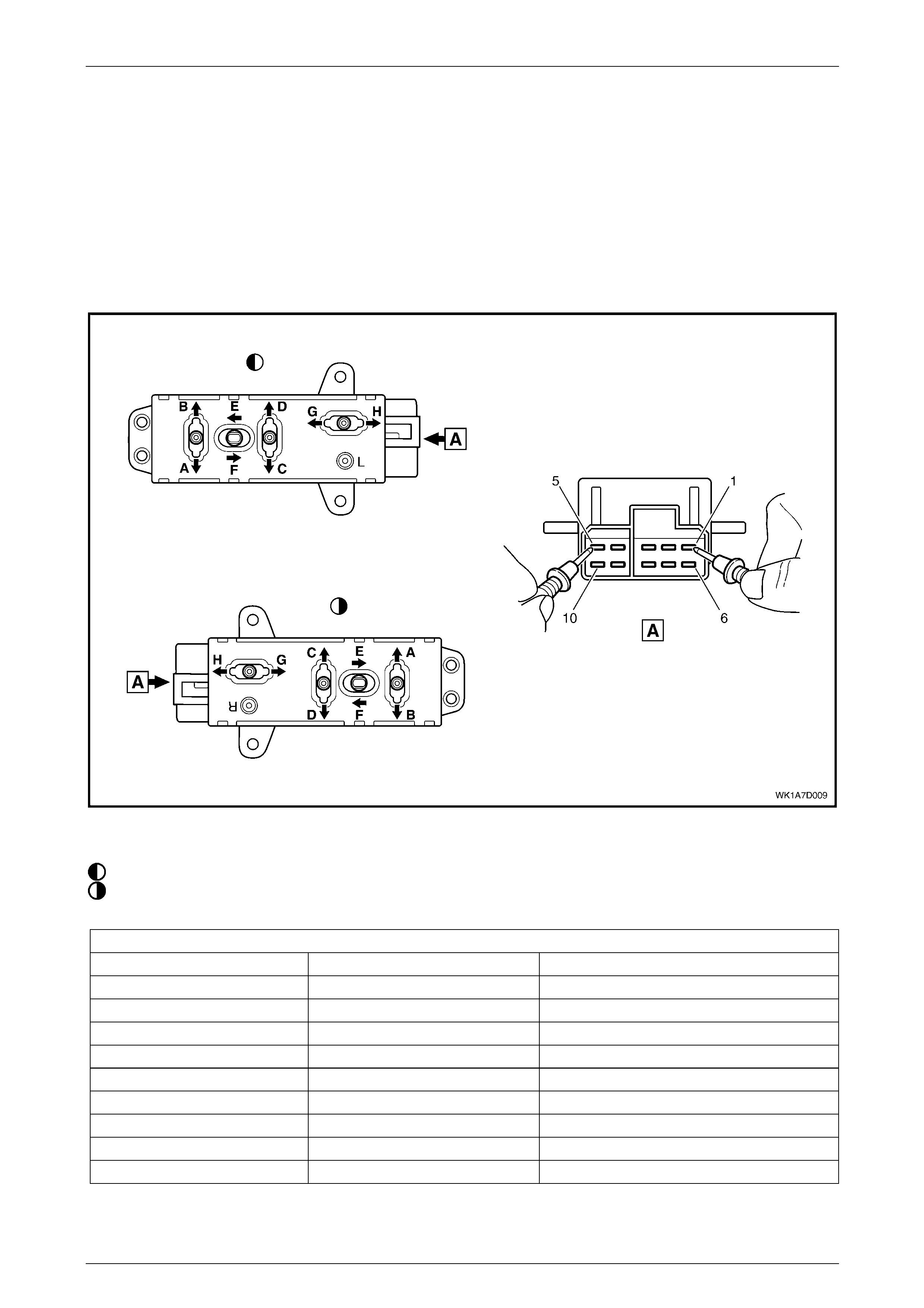
Seat Assemblies Page 1A7A–85
Page 1A7A–85
3.5 Eight-way Seat Adjustment Switch Test
The switch is located on the outer side of the seat, attached to the inner side of the front seat outer side cover.
Test
1 Remove the eight-way seat adjustment switch, refer to 5.4 Front Seat Outer Side Cover Assembly.
2 Place the switch in the positions as detailed in the chart in this Section. Place the probes of the ohmmeter onto the
terminals listed and take the reading. C ompare the reading to the chart.
3 If the switch fails any part of the test, replace the switch assembly with a serviceabl e item.
4 Install the eight-way seat adjustment switch, refer to 5.4 Front Seat Outer Side Cover Assembly.
Figure 1A7A – 14
Legend
Left-hand Switch
Right-hand Switch
Eight-way Seat Adjustment Switch
Switch Position Sw itch Terminals Indication if Switch is Serviceable
Position A 10 and 5 Continuity
Position B 7 and 5 Continuity
Position C 9 and 5 Continuity
Position D 8 and 5 Continuity
Position E 6 and 5 Continuity
Position F 3 and 5 Continuity
Position G 2 and 5 Continuity
Position H 4 and 5 Continuity
Switch in the neutral position 1 and either 2, 3, 4, 6, 7, 8, 9 or 10 Continuity

Seat Assemblies Page 1A7A–86
Page 1A7A–86
4 Diagnostics – Front Seat,
Memory and Rear-view Mirror,
Level 5
4.1 Prerequisites
Safety Requirements
When operating the seat as part of any Steps
in the diagnostic tables, ensure that fingers
and limbs are clear of mo ving parts.
Equipment
The following equipment is required to diagnose the seats:
• an unpowered test lamp with a current dra w of less than 3 A, and
• a digital multimeter with a minimum impe dance of 10 MΩ.
Testing Procedures
The following points must be adhered to
when performing diagnostic testing on
components:
• Take care when using testing equipment
to diagnose wiring harness connectors. It
is preferred that the technician backprobe
the connector to avoid terminal damage.
• When tests are required on connector
terminals, use the adapters in the
connector adapter kit KM–609 to prevent
damage to the terminals.
• Unless the multimeter being used has an
auto-ranging function, ensure the correct
range is selected.
• When backpro bing connectors, ensure the
test lamp ground lead is connected to an
appropriate ground point on the vehicle.
Ensure this ground point is not part of the
circuit being tested.
NOTE
When following the steps in th e diagnostic tables,
perform them in the order cited. If the required
nominal value or result is not achi eved, rectif y t he
problem before proceeding any further.

Seat Assemblies Page 1A7A–87
Page 1A7A–87
4.2 System Self Diagnosis
The seat memory module can self-diagnose the driver's seat and the external rear-view mirrors. When a fault or failur e is
detected, the seat memory module sets a diagnostic trouble code (DTC) that represents the fault or failure. A fault or
failure that sets a DTC may leave the seat and/or external rear-view mirrors partially or totally inoperative. If the seat
memory module detects a fault, the LED located next to the mirror dip / memory store (M) button on the memory position
switch assembly, illuminates constantly during that igniti on cycle.
Current DTCs are stored by the seat memory modul e. W hen the fault conditions are n o longer met, the DTC becomes a
History DTC.
Current DTCs
When Current DTCs are detected, they are stored by the seat memory module during the current ignition cycle. Current
DTCs are set or cleared based on the condition of the seat memory module during ignition ON or continuous monitori ng
of the current ignition cycle.
NOTE
A Current DTC is identified on the T ech 2 display
by the word Current between the DTC number
and the DTC description. The word History
between the DTC number and the DTC
description indicates that the DTC displayed is a
History DTC.
Current DTCs are reset to History DTCs upo n the next diagnostic test sequence that the fault conditions are not met.
Current DTCs can be cleared (changed to history DTC) by removing the fault conditions.
Tech 2 is unable to clear current DT Cs if the fault conditions still exist; Tech 2 will displ ay Clear DTC Information
Failed.
DTCs stored in the seat memory module can onl y be displayed and/or cleared usin g the Tech 2 diagnostic scan tool.
Tech 2 communicates with the seat memory modul e serial data using the Serial Data Link Conn ector (DLC) which is
attached to the instrument panel lower trim retainer, refer to 4.3 Tech 2 Diagnostics.
History DTCs
History DTCs are set upon the clearing of a current DTC fault condition. History DTCs are maintained by the seat
memory module over multiple ignition cycles. The seat memory module can onl y clear history DTCs from its memor y by
a CLEAR DTCS serial data message from Tech 2.
Clearing DTCs
After any system fault has been rectified, use Tech 2 Clear DTC selection to erase any fault codes stored in the seat
memory module, refer to 4.4 Tech 2 Test Modes and Displays for Diagnosis.
After DTCs have been cleared, verify proper
system operation and absence of any fault
codes. If Tech 2 displays Clear DTC
Information Failed after attempting to clear
DTCs, the fault condition still exists.
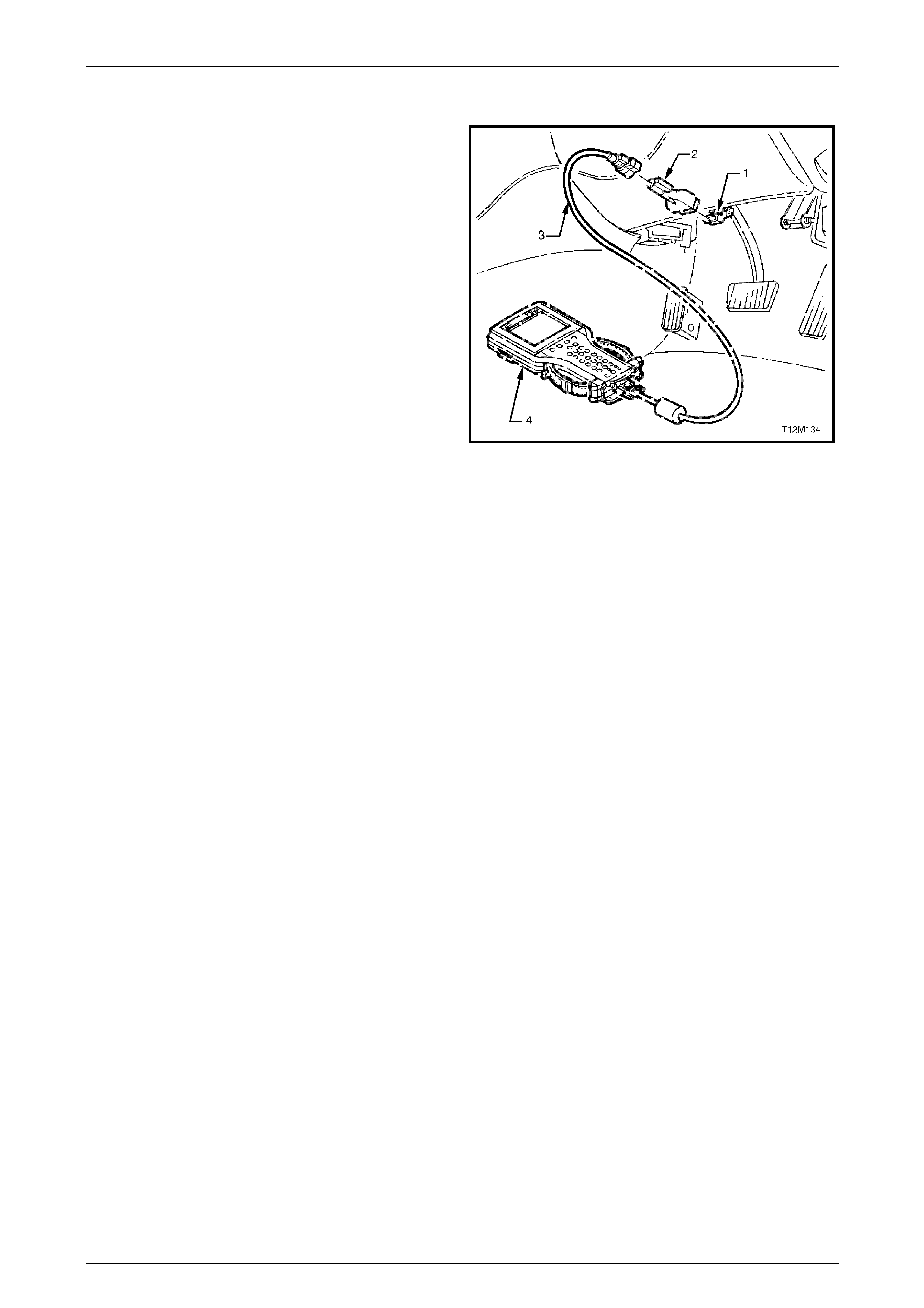
Seat Assemblies Page 1A7A–88
Page 1A7A–88
4.3 Tech 2 Diagnostics
Tech 2, with the appropriate software, cables and adapters,
when connected to the Serial Data Link Connector (DLC)
can read seat and exterior rear-view mirror serial data. The
DLC is attached to the instrument panel trim retainer
beneath the steering wheel.
1 DLC
2 DLC Adapter
3 DLC Cable
4 Tech 2
For additional general information on connecting and
operating Tech 2, refer to Section 0C Tech 2.
Figure 1A7 – 15
Test Modes
Tech 2 has five test modes for diagnosing the driver's seat and the e xter nal rear-view mirrors.
Mode F0: Diagnostic Tro uble Codes
If F0: Diagnostic Trouble Codes is selected, a selection list is displayed which contai ns:
• F0: Read DTC Information – Once this mode is selected, both current and history Diagnostic Trouble C odes
(DTCs) stored in the seat memory module's memory may be displayed.
• F1: Clear DTC Information – Once this mode is selected, DTCs stored in the seat memory module's memory may
be cleared.
Mode F1: Diagnostic Data Display
If F1: Diagnostic Data Display is selected, a selection list is displayed which contai ns:
• F0: Inputs and Outputs – Once this mode is selected, a list of system components and their inputs, outputs and
their status is displayed.
• F1: Memory – Once this mode is selected, a list of each memory position and the position of each of the seat axes
is displayed.
• F2: System Identification – Once this is selected, details including serial number of the seat memory module are
displayed.
Mode F2: Snapshot
In this test mode, Tech 2 captures seat memory module data before and af ter a forced manual trigger.
Mode F3: Miscellaneous Tests
In this test mode, Tech 2 displays a list of eight tests that can be utilised to diagnose the driver's seat and the external
rear-view mirrors, refer to 4.4 Tech 2 Test Modes and Displays for Diagnosis for further information.
Mode F4: Additional Functions
In this test mode, Tech 2 allows the technician to reset the seat, thus clearing all memory positions,
refer to 4.4 Tech 2 Test Modes and Displays for Diagnosis for further information.

Seat Assemblies Page 1A7A–89
Page 1A7A–89
4.4 Tech 2 Test Modes and Displays for
Diagnosis
A prerequisite to this diagnostic Section is for the user to be familiar with the proper use of Tech 2. T he following pages
illustrate only the major Tech 2 screen displays and provide a brief explanation of their function for diagnosing the
driver's seat and the external rear-view mirrors. If additional information is required on the oper ation of Tech 2, reference
should be made to either Section 0C Tech 2 or the Tech 2 User's Guide.
System Select Menu
With the Tech 2 connected to the DLC, and F0: Diagnostics selected from the Main Menu, the correct Model Year and
Vehicle Type must be selected for access to the System Select Menu.
Select F3: BODY.
This mode contains all functions to test, diag nose, monitor and program the vehicle's body systems including the driver's
seat and the external rear-view mirrors.
Body Application Menu
Once F3: Body has been selected from the System Select Menu, Seat and Exterior Mirror Memory Module can be
selected.
Select Seat and Exterior Mirror Memory Module.
When Seat and Exterior Mirror Memory Module is selected, the following two System Identification screens will
appear, which require action.
System Identification
Turn the ignition to the ON position with the engine not run ning (as requested) and press the Confirm soft key to
continue.
The System Identification Screen will then display information pertaining to the type of seat memory module fitted, serial
number, date of manufacture and other ancillary information. Press the Confirm soft key to continue to the Application
menu. The Identifier code for this seat is 201.
Always refer to the latest General Motors spare parts information for the correct part number.
Application Menu
The following functions will now be available:
• F0: Diagnostic Trouble Codes
• F1: Diagnostic Data Display
• F2: Snapshot
• F3: Miscellaneous Tests
• F4: Additional Functions

Seat Assemblies Page 1A7A–90
Page 1A7A–90
F0: Diagnostic Trouble Codes
If F0: Diagnostic Trouble Codes is selected from the Application menu, the following selection list is displayed:
F0: Read DTC Informa tion
If this mode is selected, a listing of all (if any) DTCs that have been set by the seat memory module will be displayed.
Information displayed with the DTC number/s that have been set, is a short description of what the DTC is, and whether
it is a current (fault present) or history (stored, but not necessarily on this ignition cycle) DTC.
Refer to Diagnostic Trouble Codes in this Section for the full listing of driver's seat and the external rear-view mirrors
DTCs with the fault identified.
NOTE
If any DTCs are set, referenc e should be m ade t o
the relevant diagnostic tables in this Section.
F1: Clear DTC Informatio n
DTCs can be cleared in this mode by selecting F1: Clear DTC Information, pressing the ENTER button on Tech 2 and
confirming the action as instructed by Tech 2.
If DTC condition is present, Tech 2 will be unable to clear the DTC and will display Clear DTC Informati on Failed.
Diagnostic Trouble Codes
The following table sets out all the possible diagnostic troubl e codes as indicated by Tech 2.
DTC Code Location Fault
1 Eight-way seat adjustment switch Front vertical up switch stuck
2 Eight-way seat adjustment switch Front vertical down switch stuck
3 Eight-way seat adjustment s witch Rear vertic al up switch stuck
4 Eight-way seat adjustment s witch Rear vertic al down switch stuck
5 Eight-way seat adjustment switch Horizontal forward switch stuck
6 Eight-way seat adjustment switch Horizontal back switch stuck
7 Eight-way seat adjustment switch Recline up switch stuck
8 Eight-way seat adjustment switch Recline down switch stuck
9 Memory position s witch assembl y Memory button 1 stuck
10 Memory position switch assembly Memory button 2 stuck
11 Memory position switch assembly Memory button 3 stuck
12 Memory position switch assembly Mirror dip button stuck
13 Seat memory module No serial data
14 Exterior rear-view mirror circuit No exterior mirror communication
19 Seat memory module ECU malfunction
20 Seat front lift motor Front vertical position sensor fault
21 Seat rear lift motor Rear vertical position sensor fault
22 Seat fore / aft movement motor Horizontal position sensor fault
23 Seat-back recline motor Recline position sensor fault
24 Seat assembly System voltage out of range

Seat Assemblies Page 1A7A–91
Page 1A7A–91
F1: Diagnostic Data Display
When F1: Diagnostic Data Display is selected, three sub-headings are displayed by Tech 2.
F0: Inputs and Outputs
F0: Inputs and Outputs displays a list of data streams for various driver's seat and external rear-view mirror
components and their current status. The table in this Section lists all the data streams with a description.
Data Stream /
Screen Display Description
Memory 1 Button Displays the state of button 1 on the memory position switch.
If button 1 on the memory position s witch assembl y is stuck in the depressed position for
more than 8 seconds, DTC 9 will be set.
• Not Pressed / Pressed
Memory 2 Button Displays the state of button 2 on the memory position switch.
If button 2 on the memory position s witch assembl y is stuck in the depressed position for
more than 8 seconds, DTC 10 will set.
• Not Pressed / Pressed
Memory 3 Button Displays the state of button 3 on the memory position switch.
If button 3 on the memory position s witch assembl y is stuck in the depressed position for
more than 8 seconds, DTC 11 will set.
• Not Pressed / Pressed
Mirror DIP Button Displays the state of the mirror dip / memory store (M) button on the memory position
switch.
If the mirror DIP / memory store (M) button on the memory position switch assembly is
stuck in the depressed position for more than 8 seconds, DTC 12 will set.
• Not Pressed / Pressed
Front Vertical Switch Displays the state of the front lift switch on the seat adjustment switch.
If the front vertical switch is stuck in the up position for more than 8 seconds, DTC 1 will set.
If the front vertical switch is stuck in the down position for more than 8 seconds, DTC 2 will
set.
• Inactive / Up / Down
Rear Vertical Switch Displays the state of the rear lift switch on the seat adjustment switch.
If the rear vertical switch is stuck in the up position for more than 8 seconds, DTC 3 will set.
If the front vertical switch is stuck in the down position for more than 8 seconds, DTC 4 will
set.
• Inactive / Up / Down
Horizontal Switch Displays the state of the horizontal switch on the seat adjustment switch.
If the horizontal switch is stuck in the forward position for more than 8 seconds, DTC 5 will
set.
If the horizontal switch is stuck in the aft position for more than 8 seconds, DTC 6 will set.
• Inactive / Forward / Back
Recline Switch Displays the state of the recline switch on the seat adjustment switch.
If the recline switch is stuck in the forward position for more than 8 seconds, DTC 7 will set.
If the recline switch is stuck in the aft position for more than 8 seconds, DTC 8 will set.
• Inactive / Forward / Back

Seat Assemblies Page 1A7A–92
Page 1A7A–92
Data Stream /
Screen Display Description
Front Vertical Position
Sensor Displays if the front lift motor position sensor is connected.
• Connected / Not Connected
Front Vertical Position
Sensor Displays the current position of the front lift motor position sensor as a value in Steps. The
Steps will range from 0 to 65535.
• 0 – 65535 Steps (typical 31 488 – 33536)
Front Vertical Position
Maximum Limit Displays the maximum limit of travel up in Steps. This value depends on the calibration of
the seat.
This value should be high but never reach 65535 Steps. If the value d isplayed is 65535, the
seat has not been calibrated. Refer to 5.3 Front Seat Assembly to calibrate the seat.
• 0 – 65535 Steps (typical 31 488 – 33536)
Front Vertical Position
Minimum Limit Displays the minimum limit of travel down in Steps. This value depends on the calibration of
the seat.
This value should be low but never reach 0 Steps. If the value displayed is 0, the seat has
not been calibrated. Refer to 5.3 Front Seat Assembly to calibrate the seat.
• 0 – 65535 Steps (typical 31 488 – 33536)
Rear Vertical Position
Sensor Displays if the rear lift motor position sensor is connected.
• Connected / Not Connected
Rear Vertical Position
Sensor Displays the current position of the rear lift motor position sensor as a val ue in Steps. The
Steps will range from 0 to 65535.
• 0 – 65535 Steps (typical 31 488 – 33536)
Rear Vertical Position
Maximum Limit Displays the maximum limit of travel up in Steps. This value depends on the calibration of
the seat.
This value should be high but never reach 65535 Steps. If the value d isplayed is 65535, the
seat has not been calibrated. Refer to 5.3 Front Seat Assembly to calibrate the seat.
• 0 – 65535 Steps (typical 31 488 – 33536)
Rear Vertical Position
Minimum Limit Displays the minimum limit of travel down in Steps. This value depends on the calibration of
the seat.
This value should be low but never reach 0 Steps. If the value displayed is 0, the seat has
not been calibrated. Refer to 5.3 Front Seat Assembly to calibrate the seat.
• 0 – 65535 Steps (typical 31 488 – 33536)
Horizontal Position Sensor Displays if the fore/aft movement motor position sensor is c onnected.
• Connected / Not Connected
Horizontal Position Sensor Displays the current position of the fore/aft movement motor position sensor as a value in
Steps. The Steps will range from 0 to 65535.
• 0 – 65535 Steps (typical 20 480 – 40960)
Horizontal Position
Maximum Limit Displays the maximum limit of travel forward in Steps. T his value depends on the calibration
of the seat.
This value should be high but never reach 65535 Steps. If the value d isplayed is 65535, the
seat has not been calibrated. Refer to 5.3 Front Seat Assembly to calibrate the seat.
• 0 – 65535 Steps (typical 20 480 – 40960)

Seat Assemblies Page 1A7A–93
Page 1A7A–93
Data Stream /
Screen Display Description
Horizontal Position
Minimum Limit Displays the minimum limit of travel aft in Steps. This value depends on the calibration of
the seat.
This value should be low but never reach 0 Steps. If the value displayed is 0, the seat has
not been calibrated. Refer to 5.3 Front Seat Assembly to calibrate the seat.
• 0 – 65535 Steps (typical 20 480 – 40960)
Recline Position Sensor Displays if the seat-back recline motor positi on sensor is connected.
• Connected / Not Connected
Recline Position Sensor Displays the current position of the seat-back recline motor position sensor as a value in
Steps. The Steps will range from 0 to 65535.
• 0 – 65535 Steps (typical 16 384 – 45056)
Recline Position Maximum
Limit Displays the maximum limit of travel forward in Steps. T his value depends on the calibration
of the seat.
This value should be high but never reach 65535 Steps. If the value d isplayed is 65535, the
seat has not been calibrated. Refer to 5.3 Front Seat Assembly to calibrate the seat.
• 0 – 65535 Steps (typical 16 384 – 45056)
Recline Position Minimum
Limit Displays the minimum limit of travel aft in Steps. This value depends on the calibration of
the seat.
This value should be low but never reach 0 Steps. If the value displayed is 0, the seat has
not been calibrated. Refer to 5.3 Front Seat Assembly to calibrate the seat.
• 0 – 65535 Steps (typical 16 384 – 45056)
Button Pack
Communication Displays whether there is serial data communicati on with the mirror control switch,
right-hand or left-hand rear-view mirrors. If there is communication with at least one of these
components, Tech 2 will displa y Okay. If there is no communications with all of the
components, Tech 2 will displa y Not Okay.
If there are no serial data communications, a DTC 14 will set.
• Okay / Not Okay
Right Exterior Mirror
Communication Displays if Tech 2 can communic ate with the right-hand exterior rear-view mirror.
If there is not serial data communications with the right-hand exterior rear-view mirror, a
DTC 14 will set.
• Okay / Not Okay
Left Exterior Mirror
Communication Displays if Tech 2 can communic ate with the left-hand exterior rear-view mirror.
If there is not serial data communications with the left-hand exterior rear-view mirror, a DTC
14 will set.
• Okay / Not Okay
Right Exterior Mirror Switch Displays the status of the mirror control switch, when the rocker switch is selected to right.
• Up / Down / Left / Right / Inactive
Left Exterior Mirror Switch Displays the status of the mirror control switch, when the rocker switch is selected to left.
• Up / Down / Left / Right / Inactive
Memory Recall Position In
Use Displays the status of the current memory recall of the seat assembly.
• Memory 1 / Memory 2 / Memory 3 / Priority 1 / Priority 2 / No Active Memory
Current Priority Displays what is the current priority that has been set when the vehicle is unlocked with
either priority key 1 or 2.
• Priority 1 / Priority 2 / No Active Memory

Seat Assemblies Page 1A7A–94
Page 1A7A–94
Data Stream /
Screen Display Description
Able To Recall Displays if the seat assembly has the ability to recall a memory position.
• Yes / No
Start Wait Active Only when there has been a cold-start reset will Tech 2 display No. A cold-start reset will
occur when module detects too much electro m agnetic interference (EMI) in the system. If
the Start Wait Active displays No, the system will still be operational.
• Yes / No
Able To Move When the seat is requested to move, the seat memory module monitors the amou nt of
Steps that a position sensor has taken during that movement. This inability to move at all or
quickly enough may be due to a physical restriction in that movement, or the battery not
having enough charge to power the particular motor adequately.
• Yes / No
Ignition Switch Displays the status of the ignition switch.
• On / Off / Accessory
Demist Request Displays the status of the rear demist system. This will be Yes when the rear demist button
is pressed.
• Yes / No
Reverse Gear Displays if the vehicle is in reverse gear.
• Inactive / Active
PRNDL Position Displays the position of the transmission selector.
• P / R / N / D / 3 / 2 / 1
F1: Memory
F1: MEMORY displays all the five memory settings availabl e. Within each of the memory settings the position of the seat
is displayed (in Steps) and if the mirror dip function is enabled.
Data Stream /
Screen Display Description
Memory 1 Mirror Dip Status Displays if the mirror dip function is enabled for Memory 1.
• Enabled / Disabled
Memory 1 Front Vertical
Position Displays the seat front vertical position (in Steps) that has been store d in Memory 1.
• 0 – 65535 Steps (typical 31 488 – 33536)
Memory 1 Rear Vertical
Position Displays the seat rear vertical position (in Steps) that has been stored in Memory 1.
• 0 – 65535 Steps (typical 31 488 – 33536)
Memory 1 Horizontal
Position Displays the seat horizontal position (in Steps) that has been stored in Memory 1.
• 0 – 65535 Steps (typical 20 480 – 40960)
Memory 1 Recline Position Displays the seat-back recline position (in Steps) that has been stored in Memory 1.
• 0 – 65535 Steps (typical 16 384 – 45056)
Memory 2 Mirror Dip Status Displays if the mirror dip function is enabled for Memory 2.
• Enabled / Disabled
Memory 2 Front Vertical
Position Displays the seat front vertical position (in Steps) that has been store d in Memory 2.
• 0 – 65535 Steps (typical 31 488 – 33536)
Memory 2 Rear Vertical
Position Displays the seat rear vertical position (in Steps) that has been stored in Memory 2.
• 0 – 65535 Steps (typical 31 488 – 33536)

Seat Assemblies Page 1A7A–95
Page 1A7A–95
Data Stream /
Screen Display Description
Memory 2 Horizontal
Position Displays the seat horizontal position (in Steps) that has been stored in Memory 2.
• 0 – 65535 Steps (typical 20 480 – 40960)
Memory 2 Recline Position Displays the seat-back recline position (in Steps) that has been stored in Memory 2.
• 0 – 65535 Steps (typical 16 384 – 45056)
Memory 3 Mirror Dip Status Displays if the mirror dip function is enabled for Memory 3.
• Enabled / Disabled
Memory 3 Front Vertical
Position Displays the seat front vertical position (in Steps) that has been store d in Memory 3.
• 0 – 65535 Steps (typical 31 488 – 33536)
Memory 3 Rear Vertical
Position Displays the seat rear vertical position (in Steps) that has been stored in Memory 3.
• 0 – 65535 Steps (typical 31 488 – 33536)
Memory 3 Horizontal
Position Displays the seat horizontal position (in Steps) that has been stored in Memory 3.
• 0 – 65535 Steps (typical 20 480 – 40960)
Memory 3 Recline Position Displays the seat-back recline position (in Steps) that has been stored in Memory 3.
• 0 – 65535 Steps (typical 16 384 – 45056)
Priority 1 Mirror Dip Status Displays if the mirror dip function is enabled for Priority 1.
• Enabled / Disabled
Priority 1 Front Vertical
Position Displays the seat front vertical position (in Steps) that has been stored in P riority 1.
• 0 – 65535 Steps (typical 31 488 – 33536)
Priority 1 Rear Vertical
Position Displays the seat rear vertical position (in Steps) that has been stored in Priority 1.
• 0 – 65535 Steps (typical 31 488 – 33536)
Priority 1 Horizontal
Position Displays the seat horizontal position (in Steps) that has been stored in Priority 1.
• 0 – 65535 Steps (typical 20 480 – 40960)
Priority 1 Recline Position Displays the seat-back recline position (in Steps) that has been stored in Priority 1.
• 0 – 65535 Steps (typical 16 384 – 45056)
Priority 2 Mirror Dip Status Displays if the mirror dip function is enabled for Priority 2.
• Enabled / Disabled
Priority 2 Front Vertical
Position Displays the seat front vertical position (in Steps) that has been stored in P riority 2.
• 0 – 65535 Steps (typical 31 488 – 33536)
Priority 2 Rear Vertical
Position Displays the seat rear vertical position (in Steps) that has been stored in Priority 2.
• 0 – 65535 Steps (typical 31 488 – 33536)
Priority 2 Horizontal
Position Displays the seat horizontal position (in Steps) that has been stored in Priority 2.
• 0 – 65535 Steps (typical 20 480 – 40960)
Priority 2 Recline Position Displays the seat-back recline position (in Steps) that has been stored in Priority 2.
• 0 – 65535 Steps (typical 16 384 – 45056)
F2: System Identification
F2: System Identification displays the specifications of the seat memory module, refer to System Identification with i n
this Section.

Seat Assemblies Page 1A7A–96
Page 1A7A–96
F2: Snapshot
In this mode, Tech 2 captures seat memory module data b efore and after a forced manual trigger.
F3: Miscellaneous Tests
In this mode, a list of tests are displayed that can be used to control certain functions of the driver's seat and the exterior
rear-view mirrors.
F0: Chime
When this test is selected, menu keys are availabl e. To activate the chime function of the seat memory module, press
the On key. The chime will then sound continuously. To turn off the chime, press the Off key. To return to
F3: Miscellaneous Tests menu, press the Quit key.
In this test, the input and output data is also displayed, refer to F0: Inputs and Outputs in this Section.
F1: LED
When this test is selected, menu keys are availabl e. To activate the LED function of the seat memory module, press the
Flash key. The LED will flash. To return to F3: Miscellaneous Tests menu, press the Quit key.
In this test, the input and output data is also displayed, refer to F0: Inputs and Outputs in this Section.
F2: Right Exterior Mirror
When this test is selected, the arrow keys on Tech 2 can be used to drive the right-hand exterior mirror in all four
directions. During this test the data stream for the right-hand exterior mirror will be displayed. The data stream will
change from off to the direction pressed.
F3: Left Exterior Mirror
When this test is selected, the arrow keys on Tech 2 can be used to drive the left-hand exterior mirror in all four
directions. During this test the data stream for the left-hand exterior mirror will be displayed. The data stream will change
from off to the direction pressed.
F4: Front Vertical Motor
When this test is selected, menu keys are available. To drive the front lift motor up, press the Up key and alternatively to
move the front lift motor down, press the Down key.
F5: Rear Vertical Mirror
When this test is selected, menu keys are available. To drive the rear lift motor up, press the Up key and alternatively to
move the rear lift motor down, press the Down key.
F6: Horizontal Motor
When this test is selected, menu keys are availabl e. To drive the seat fore/aft movement motor forward, press the
Forward key and alternatively to move the seat fore/aft movement motor aft, press the Back key.
F7: Recline Motor
When this test is selected, menu keys are availabl e. To drive the seat-back recline motor for ward, press the Forward key
and alternatively to move the seat-back recline motor aft, press the Back key.

Seat Assemblies Page 1A7A–97
Page 1A7A–97
F4: Additional Functions
F0: Module Reset
This function clears all the preset memories i ncluding any priority key that the seat memory module has stored.
When this function is selected, menu keys are available. Tech 2 will prompt with the message Do you Really Want To
Reset. To reset the module, press the Yes key. If the technician does not want to reset the module, press the No key
and to return the F4: Additional Functions menu.

Seat Assemblies Page 1A7A–98
Page 1A7A–98
4.5 Preliminary System Diagnosis
Prior to starting any diagnosis, the technician should be familiar with the driver's seat and the external rear-view mirror
components and operation. For a descri ptio n of the components and the system operation,
refer to 1 General Information.
When investigating any complaint of a problem or malfunction, always begin diagnos is wit h a circu it check, refer to
4.8 Electrical Diagnosis – Memor y Seat, Ini tial Check for a seat fault, or
4.10 Electrical Diagnosis – Rear-view Mirrors, Initial Check for an exterior rear-view mirror fault. If the complaint is of a
mechanical nature, refer to 4.7 Mechanical Diag nosis.
The diagnostic circuit check ensures that the driver's seat and the external rear-view mirrors are communicating on the
serial data line as well as assi sting to identify the problem and to ascertai n the appropriate diagnostic table in this
Section.

Seat Assemblies Page 1A7A–99
Page 1A7A–99
4.6 Diagnostic Tables
Introduction
The following diagnostic tables are designed to provide fast and efficient fault location and remedy. The diagnostic tables
include a chart, pertinent information, circuit diagrams, and where necessary, the steps are explained by the
corresponding numbered paragraphs.
When performing wiring checks as directed to by the diagnostic tables, rather than probe pins and connectors with
incorrect sized multimeter connectio ns, use the ad apters contained in connector test adapter kit Tool No. KM-609 and
test lead set Tool No. KM609-20. This will prevent any possibility of spreading or damaging wiring harness pins and
causing a system intermittent failure.

Seat Assemblies Page 1A7A–100
Page 1A7A–100
4.7 Mechanical Diagnosis
Lumbar Support Inoperative
Introduction
This test is used to aid in diagnosing the lumbar support assembly.
Test Description
The following numbers refer to the step numbers in the diagnostic table:
1 Checks if the lumbar support knob is properly engaging the lumbar support adjuster. Check the knob for cracks and
worn splines.
2 Checks if the lumbar support assembly is damage d or worn and if the retaining springs are serviceable and
securely attached to the seat-back frame assembly.
3 Checks if the lumbar support assembly is serviceable and if the lumber support assembly strap is operating
correctly within the guide rails.
Diagnostic Table
Step Action Yes No
1 Remove the lumbar support knob, refer to 5.9 Lumbar Su pport Knob
Assembly.
Is the lumbar support adjust knob serviceable? Go to Step 2
Replace the knob,
refer to 5.9 Lumbar
Support Knob
Assembly
2 1 Remove the seat-back cover.
2 Inspect the lumbar support retainers and spri ngs.
Are the lumbar support retaining spri ngs serviceable and securely
attached to the seat-back frame assembly? Go to Step 3
Replace or reattach
the retaining
springs, refer to
5.11 Front
Seat-back Frame
Assembly
3 1 Visually inspect the lumbar support assembly. Check for broken
or worn parts.
2 Check the strap running across the lumber s upport assembly is
serviceable and running freely within the guide rails.
NOTE
You may need to attach the lumber support knob to
actuate the strap.
Is the lumbar support assembly serviceabl e? System serviceable
Replace lumbar
support assembly or
resecure lumbar
support assembly
strap ensuring strap
is not binding with
guide rails, refer to
5.11 Front
Seat-back Frame
Assembly
When all diagno sis and repairs are completed, ch eck the system for correct operation.
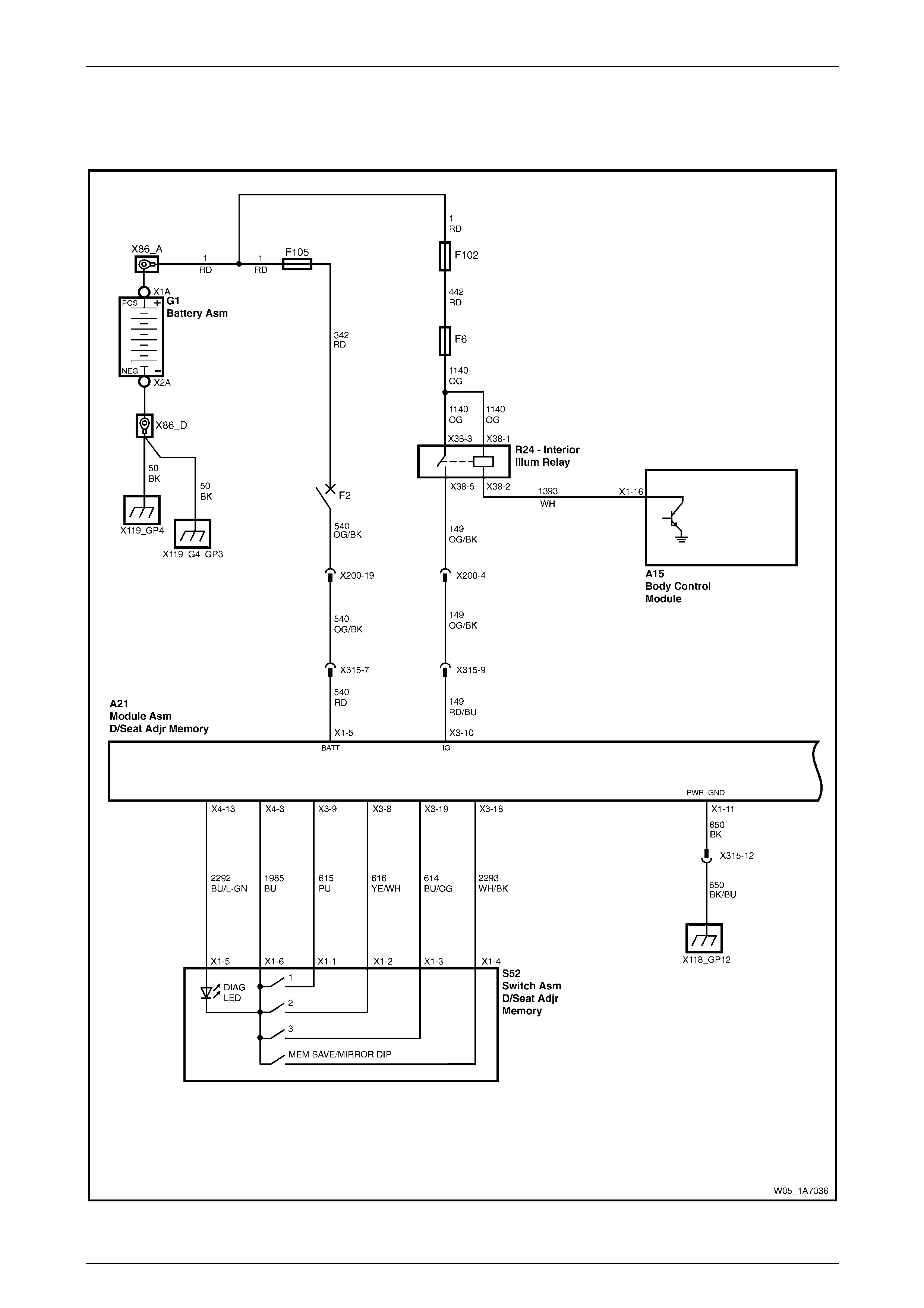
Seat Assemblies Page 1A7A–101
Page 1A7A–101
4.8 Electrical Diagnosis – Memory Seat
Wiring Diagram – Memory Seat, RHD
Figure 1A7A – 16
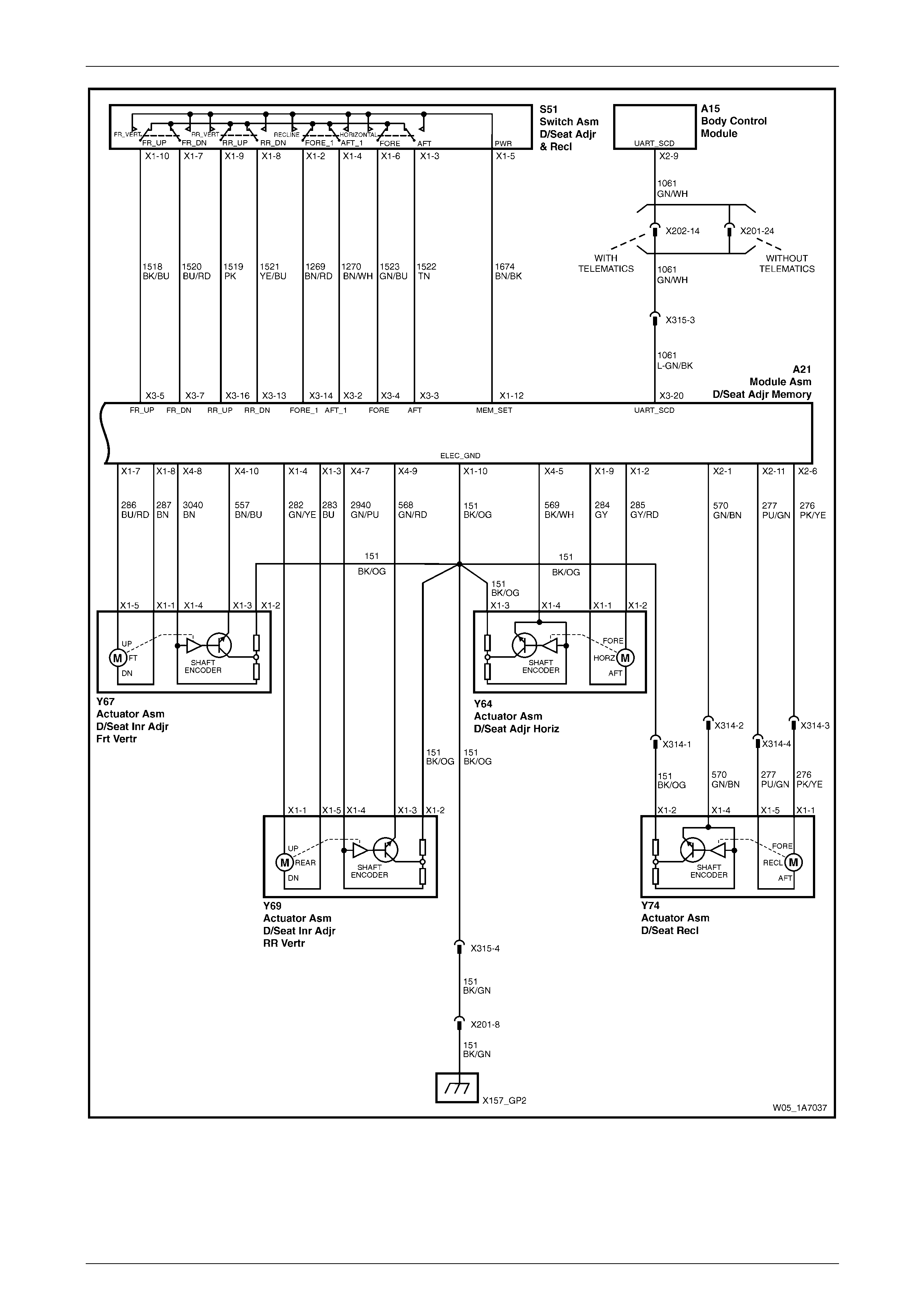
Seat Assemblies Page 1A7A–102
Page 1A7A–102
Figure 1A7A – 17
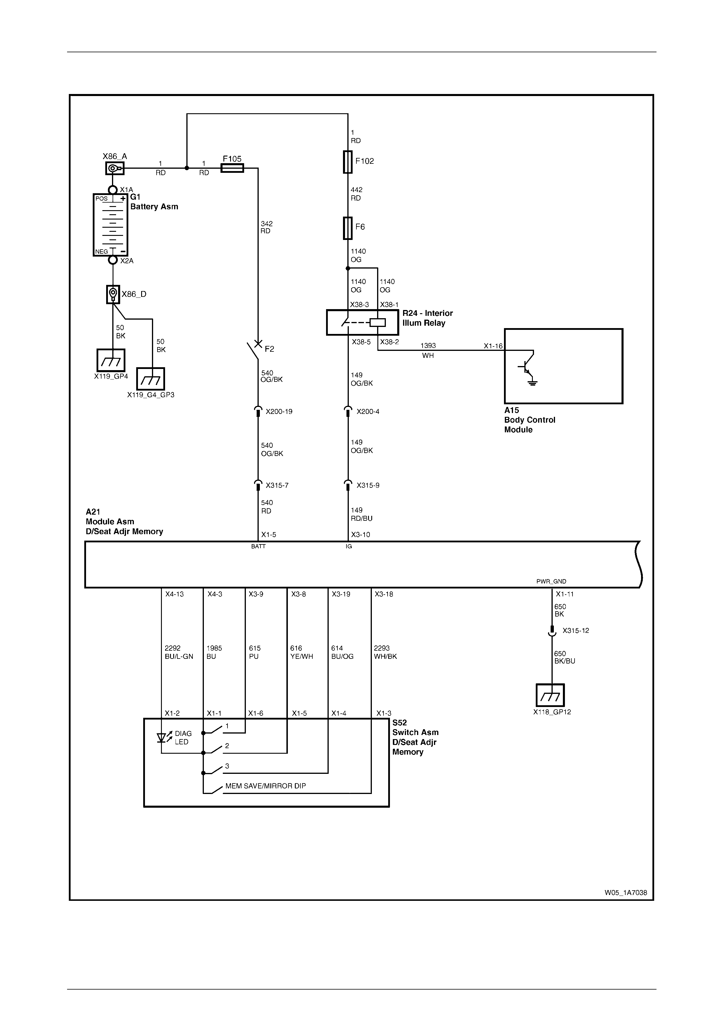
Seat Assemblies Page 1A7A–103
Page 1A7A–103
Wiring Diagram – Memory Seat, LHD
Figure 1A7A – 18
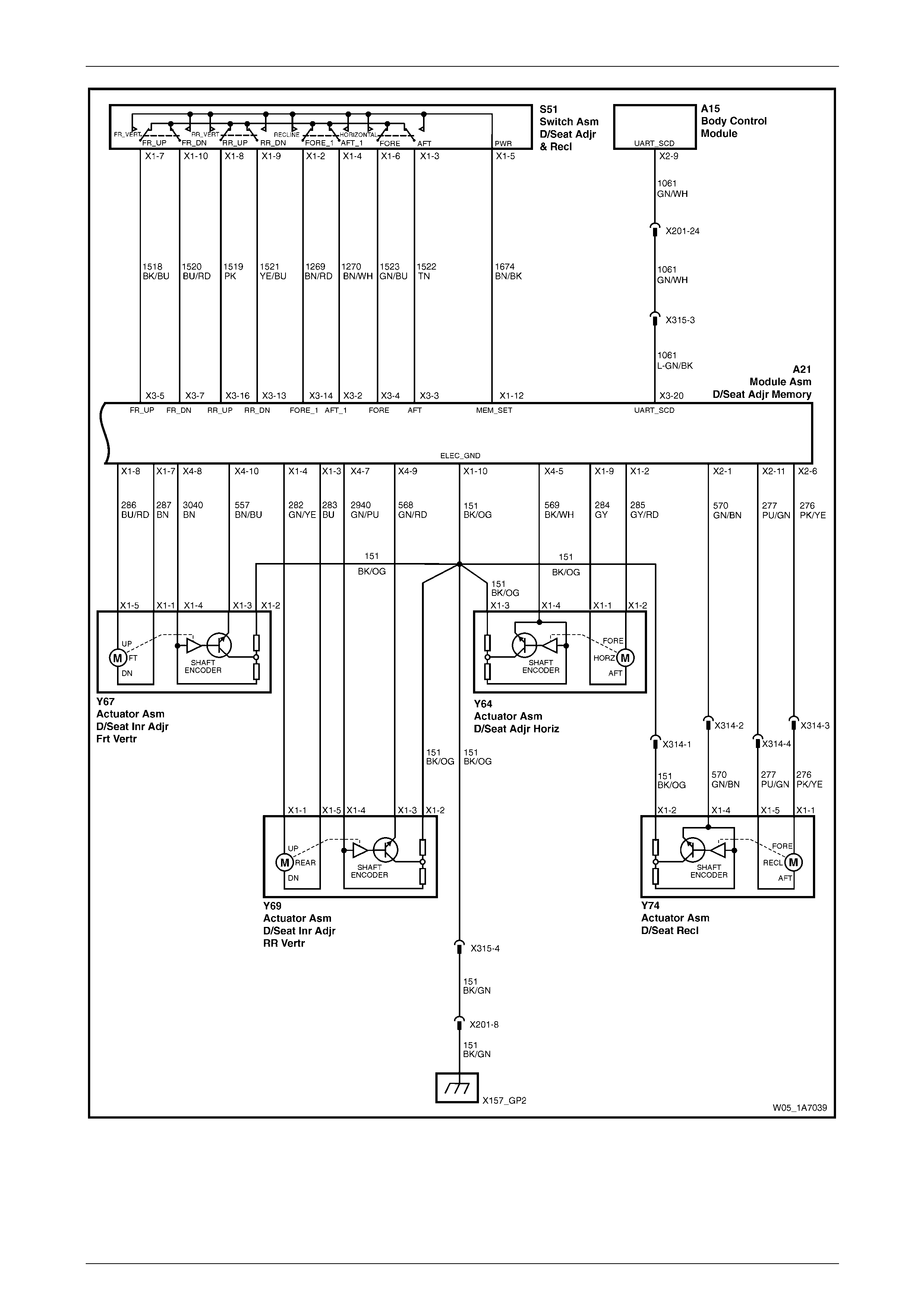
Seat Assemblies Page 1A7A–104
Page 1A7A–104
Figure 1A7A – 19
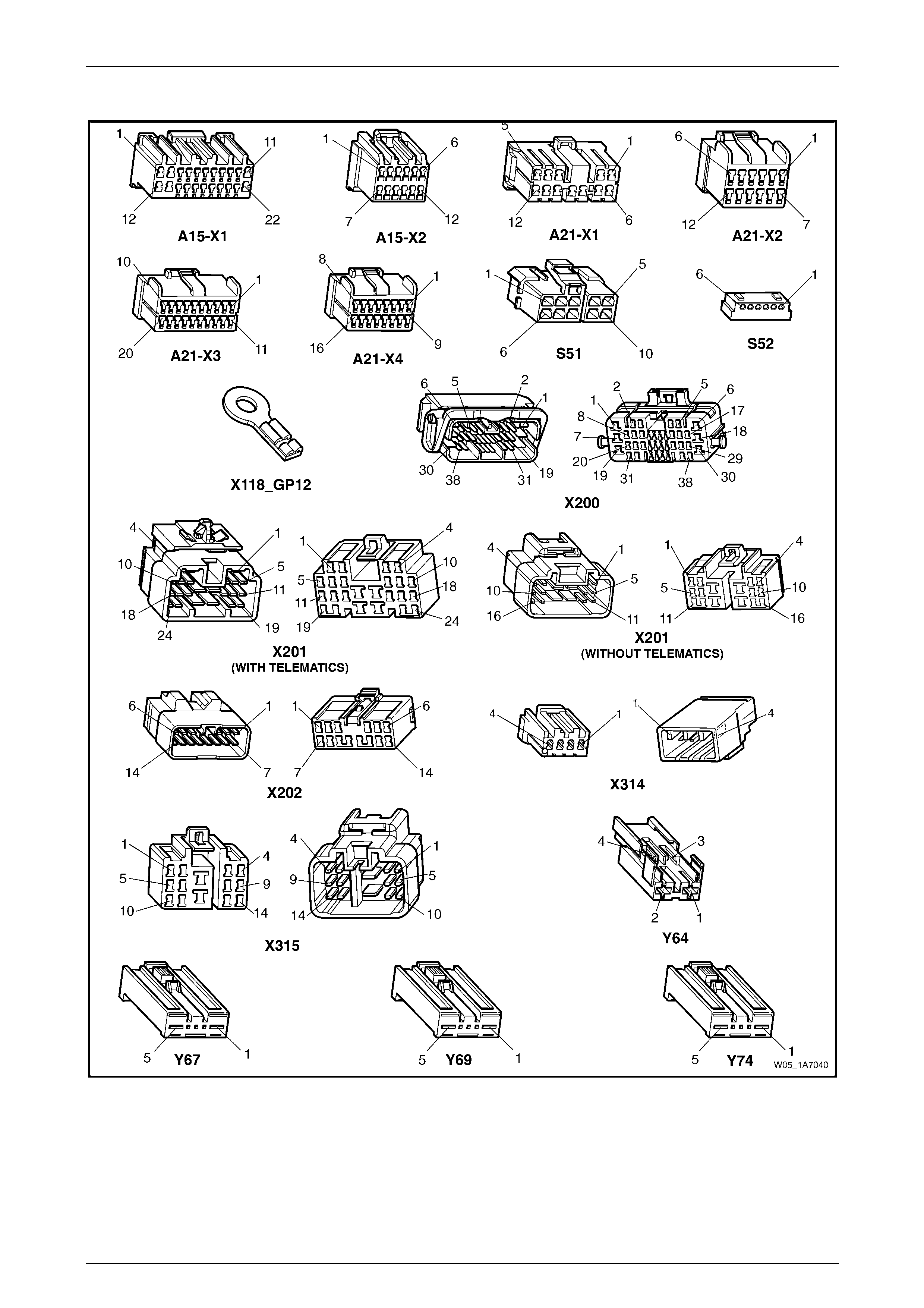
Seat Assemblies Page 1A7A–105
Page 1A7A–105
Connector Chart – Memory Seat
Figure 1A7A – 20

Seat Assemblies Page 1A7A–106
Page 1A7A–106
Initial Check
Introduction
The driver's seat and exterior rear-view mirrors can be diagnosed using T ech 2. The diagnostic table tests each function
of the seat for correct operation.
Test Description
The following numbers refer to the step numbers in the diagnostic table:
1 Checks if the fault is isolated to the driver’s seat.
2 If Tech 2 cannot access the System Identification menu there is a problem with the power, serial data
communications or ground cir cuits to the memory module.
3 Checks if there are any current DTCs.
4-11 Checks if the seat adjustment switch is serviceable. Also checks if the associated motor circuits are serviceable.
12 Using Tech 2, checks if the memory position s witch assembly is operational.
13 Checks if the seat front lift motor hall-effect sensor is connected.
14 Checks if the seat front lift motor hall-effect sensor (in Steps) has an acceptable maximum, minimum value and
current seat position is within that rang e.
15 Checks if the seat rear lift motor hall-effect sensor is connected.
16 Checks if the seat rear lift motor hall-effect sensor (in Steps) has an acce ptable maximum, minimum val ue and
current seat position is within that rang e.
17 Checks if the seat horizontal motor hall-effect sensor is connected.
18 Checks if the seat horizontal motor hall-effect sensor (in Steps) has an acceptable maximum, minimum value and
current seat position is within that rang e.
19 Checks if the seat recline motor hall-effect sensor is connected.
20 Checks if the seat recline mot or hal l-effect sensor (in Steps) has an acceptable ma ximum, minimum value and
current seat position is within that rang e.
21 Checks if the seat memory module stores a different seat position for each of the three memory buttons. Checks if
when each of the memory buttons are pressed, the seat moves to the stored position and Tech 2 displays the
correct information.
22 Checks if the seat recalls a priority key memory position.

Seat Assemblies Page 1A7A–107
Page 1A7A–107
Diagnostic Table
Step Action Yes No
1 Are all of the passenger’s seat adjustment switch functions
inoperative? Refer to Neither
Seat Adjustment
Switch Functions
Operate in 3.3
Electrical Diagnosis
– Eight-way Seat,
Non-memory, RHD Go to Step 2
2 1 Connect Tech 2 to the DLC.
2 On Tech 2 select:
Body / Seat and Exterior Mirror Memory Module.
3 Turn the ignition on when prompted.
Is the Seat and Exterior Mirror Module System Identification
specifications displayed? Go to Step 3
Refer to
No Serial Data
Communications to
the Seat Memory
Module
3 On Tech 2 select:
Body / Seat and Exterior Mirror Memory Module / Diagnostic
Trouble Codes / Read DTC Information.
Are there any DTCs set?
Refer to the relevant
DTC diagnostic
table in this Section Go to Step 4
4 1 Connect Tech 2 to the DLC.
2 On Tech 2 select:
Body / Seat and Exterior Mirror Memory Module / Diagnostic
Data Display / Inputs and Outputs.
3 Scroll to Front Vertical Switch.
4 While monitoring Tech 2, operate the seat a djustme nt switch to
raise and lower the front of the seat.
Does Tech 2 display the fol lowing:
• Inactive when the switch is in the neutral position.
• Up when the switch is in the up positio n.
• Down when the switch is in the down positio n. Go to Step 5
Refer to Seat
Adjustment Switch
Inoperative – RHD
or Seat Adjustment
Switch Inoperative –
LHD
5 During the test in Step 4, does the front of the seat move in the
following directions?
• When the switch is in the neutral position, the front of the seat
does not move.
• When the switch is in the up position, the front of the seat raises.
• When the switch is in the down position, the front of the seat
lowers. NOTE
Ensure that the seat is not at its maximum limit of travel
before performing this test. Go to Step 6
Seat Front Lift Motor
Inoperative – RHD
or Seat Front Lift
Motor Inoperative –
LHD
6 1 On Tech 2 select:
Rear Seat Vertical Switch.
2 While monitoring Tech 2, operate the seat a djustme nt switch to
raise and lower the rear of the seat.
Does Tech 2 display the fol lowing:
• Inactive when the switch is in the neutral position.
• Up when the switch is in the up positio n.
• Down when the switch is in the down positio n. Go to Step 7
Refer to Seat
Adjustment Switch
Inoperative – RHD
or Seat Adjustment
Switch Inoperative –
LHD

Seat Assemblies Page 1A7A–108
Page 1A7A–108
Step Action Yes No
7 During the test in Step 6, does the rear of the seat move in the
following directions?
• When the switch is in the neutral position, the rear of the seat
does not move.
• When the switch is in the up position, the rear of the seat raises.
• When the switch is in the down position, the rear of the seat
lowers. NOTE
Ensure that the seat is not at its maximum limit of travel
before performing this test. Go to Step 8 Seat Rear Lift Motor
Inoperative
8 1 On Tech 2 select:
Horizontal Switch.
2 While monitoring Tech 2, operate the seat a djustme nt switch to
move the seat forward and aft.
Does Tech 2 display the fol lowing:
• Inactive when the switch is in the neutral position.
• Forward when the switch is in the forward position.
• Back when the switch is in the aft position. Go to Step 9
Refer to Seat
Adjustment Switch
Inoperative – RHD
or Seat Adjustment
Switch Inoperative –
LHD
9 During the test in Step 8, does the seat move in the following
directions?
• When the switch is in the neutral position, the seat does not
move.
• When the switch is in the forward position, the seat moves
forward.
• When the switch is in the aft position, the seat moves aft.
NOTE
Ensure that the seat is not at its maximum limit of travel
before performing this test. Go to Step 10
Refer to Seat
Fore/Aft Movement
Motor Inoperative
10 1 On Tech 2 select:
Recline Switch.
2 While monitoring Tech 2, operate the seat a djustme nt switch to
move the seat-back forward and aft.
Does Tech 2 display the fol lowing:
• Inactive when the switch is in the neutral position.
• Forward when the switch is in the forward position.
• Back when the switch is in the aft position. Go to Step 11
Refer to Seat
Adjustment Switch
Inoperative – RHD
or Seat Adjustment
Switch Inoperative –
LHD
11 During the test in Step 10, does the seat-back move in the following
directions?
• When the switch is in the neutral position, the seat-back does
not move.
• When the switch is in the forward position, th e seat-back moves
forward.
• When the switch is in the aft position, the seat-back moves aft.
NOTE
Ensure that the seat is not at its maximum limit of travel
before performing this test. Go to Step 12
Refer to Seat
Fore/Aft Movement
Motor Inoperative
12 1 On Tech 2 select:
Memory Button 1.
2 While monitoring Tech 2, press the following buttons:
• Memory button 1
• Memory button 2
• Memory button 3
• Mirror dip / memory button
Does Tech 2 display Active next to the corresponding button? Go to Step 13
Refer to Memory
Position Switch
Inoperative – RHD
or Memory Position
Switch Inoperative –
LHD

Seat Assemblies Page 1A7A–109
Page 1A7A–109
Step Action Yes No
13 On Tech 2 select:
Front Vertical Position Sensor.
Does Tech 2 display the hal l-effect sensor is Connected? Go to Step 14
Seat Front Lift Motor
Hall-effect Sensor
Check
14 1 On Tech 2 select:
Front Vertical Position Maximum Limit.
2 Check the following values displayed on Tech 2:
• Front Vertical Maximum Position Limit. This should be
less than 65535 Steps.
• Front Vertical Minimum Position Limit. This should be
more than 0 Steps.
• Front Vertical Position Sensor. This value should be
between the minimum and maximum values. Go to Step 15
Disconnect battery
power from the seat
and perform the
calibration
procedure, refer to
5.3 Front Seat
Assembly
15 On Tech 2 select:
Rear Vertical Position Sensor.
Does Tech 2 display the hal l-effect sensor is Connected? Go to Step 16
Refer to Seat Rear
Lift Motor Hall-effect
Sensor Check
16 1 On Tech 2 select:
Rear Vertical Position Maximum Limit.
2 Check the following values displayed on Tech 2:
• Rear Vertical Maximum Position Limit. This should be
less than 65535 Steps.
• Rear Vertical Minimum Position Limit. This should be
more than 0 Steps.
• Rear Vertical Position Sensor. This value should be
between the minimum and maximum values. Go to Step 17
Disconnect battery
power from the seat
and perform the
calibration
procedure, refer to
5.3 Front Seat
Assembly
17 On Tech 2 select:
Horizontal Position Sensor.
Does Tech 2 show the hall-effect sensor is Connected? Go to Step 18
Refer to Seat
Fore/Aft Movement
Motor Hall-effect
Sensor Check
18 1 On Tech 2 select:
Horizontal Position Maximum Limit.
2 Check the following values displayed on Tech 2:
• Horizontal Maximum Position Limit. This should be less
than 65535 Steps.
• Horizontal Minimum Position Limit. This should be more
than 0 Steps.
• Horizontal Position Sensor. This value should be
between the minimum and maximum values. Go to Step 19
Disconnect battery
power from the seat
and perform the
calibration
procedure, refer to
5.3 Front Seat
Assembly
19 On Tech 2 select:
Recline Position Sensor.
Does Tech 2 show the hall-effect sensor is Connected? Go to Step 20
Refer to Seat-back
Recline Motor
Inoperative
20 1 On Tech 2 select:
Recline Position Maximum Limit.
2 Check the following values displayed on Tech 2:
• Recline Maximum Position Limit. This should be less
than 65535 Steps.
• Recline Minimum Position Limit. This should be more
than 0 Steps.
• Recline Position Sensor. This value should be between
the minimum and maximum valu es. Go to Step 21
Disconnect battery
power from the seat
and perform the
calibration
procedure, refer to
5.3 Front Seat
Assembly

Seat Assemblies Page 1A7A–110
Page 1A7A–110
Step Action Yes No
21 1 Store a new memory position in each of the available positions
(Memory Button 1, 2 and 3), refer to 1 General Information for
instructions (or the Owner Manual).
NOTE
When a seat position is stored into the relevant memory
position, the seat will chime. For each of the memory
positions, confirm the chime.
2 After the last position has been stored in memory, move the seat
out of that position.
3 On Tech 2 select:
Memory Recall Position. Tech 2 should display No Active
Memory.
4 While monitoring Tech 2, press memor y but t on 1. The seat will
move to the stored position and Tech 2 will display Memory
Button 1 while the button is pressed. When the seat comes to a
stop and the button is released, does Tech 2 display Memory
Button 1.
5 While monitoring Tech 2, press memor y but t on 2. The seat will
move to the stored position and Tech 2 will display Memory
Button 2. When the seat comes to a stop and the button is
released, does Tech 2 display Memory Button 2.
6 While monitoring Tech 2, press memor y but t on 3. The seat will
move to the stored position and Tech 2 will display Memory
Button 3. When the seat comes to a stop, does Tech 2 display
Memory Button 3.
Does Tech 2 display the relevant memory positions as described in
this test? Go to Step 22
Replace the seat
memory module,
refer to 5.12 Seat
Cable Tray and
Memory Module
22 NOTE
To perform this test, both keys supplied with the vehicle
are needed.
1 On Tech 2 select:
Current Priority and ensure that No Active Memory is
displayed.
2 Disconnect Tech 2 from the vehicle.
3 Using the seat adjustment switch, move the seat to a new
position and lock the car with the Remote Control from Ke y 1.
4 Unlock the vehicle with the Remote Control from Key 1.
5 Connect Tech 2 to the DLC.
6 On Tech 2 select:
Body / Seat and Exterior Mirror Memory Module / Diagnostic
Data Display / Inputs and Outputs and scroll to Current
Priority.
Does Tech 2 display e ither Priority 1 or Priority 2? System serviceable Refer to Priority Key
Feature Inoperative
When all diagno sis an d repairs are completed, clear all DT Cs an d check the system for correct operation.

Seat Assemblies Page 1A7A–111
Page 1A7A–111
No Serial Data Communications to the Seat Memory Module
Introduction
For Tech 2 to communicate with the seat memory module, the following must be satisfied:
• There must be no faults in the serial data bus. If there is a fault, it can be caused at any where on the bus and
consist of a short to ground or battery, or an open circuit.
• There must be power and ground circuit to the seat memory module.
If either of these problems exist, Tech 2 will not communicate with either the seat memory module or the entire serial
data bus, depending on where the fault is.
Refer to Wiring Diagram – Memory Seat, RHD, Wiring Diagram – Memory Seat, LHD and
Connector Chart – Memory Seat to aid in diagnosing the seat memory module an d associated components.
Test Description
The following numbers refer to the step numbers in the diagnostic table:
1 Checks if Tech 2 is able to communicate with other modules in the vehicle. Isolates whether the problem is with the
seat memory module and its circuits or with the serial data bus.
2 Checks if circuit breaker F2 is serviceable.
3 Checks if there is battery supply to the seat memory module at connector A21 – X1.
4 Circuit 650 provides a ground circuit for the seat memory module. Checks if there is an open circuit in circuit 650.
5 Circuit 151 provides a ground circuit for the seat memory module. Checks if there is an open circuit in circuit 151.
6 Checks if there is continuity in the serial data line between the seat memory module and the BCM.
7 Checks if fusible link F105 is serviceable.
8 Checks for battery voltage at connector X200 pin 19. Isolates whether there is a fault in circuit 540 between
connectors X200 and A21–X1 or between X200 and circuit breaker F2.
Diagnostic Table Notes
1 For all wiring harness fault diagnoses, refer to Section 12P Wiring Diagram s.
2 For wiring harness repairs, refer to Section 12P Wiring Diagrams.
3 Refer to Section 12O Fuses, Relays and Wiring Harnesses for harness routeing.
4 If the fault is deemed to be intermittent, refer to Section 12P Wiring Diagrams.

Seat Assemblies Page 1A7A–112
Page 1A7A–112
Diagnostic Table
Step Action Yes No
1 1 Connect Tech 2 to the DLC.
2 Turn the ignition to the ON position with the engine not running.
3 On Tech 2 select:
Body / DTC Check / DTC Check and press the Confirm soft
key when instructed. If No Data is displayed next to a control
module, there is no communication b etween Tech 2 and that
particular control module.
Does Tech 2 communicate with the BCM and the PCM? Go to Step 2 Refer to 12J Body
Control Module
2 1 Disconnect Tech 2 from the DLC.
2 Check the circuit breaker F2, located on the passenger
compartment fuse and relay panel.
Is the circuit breaker F2 serviceable?
Go to Step 3
Allow the circuit
breaker to reset
(refer to Note 3).
If the circuit breaker
trips again, repair or
replace circuit 540
(refer to Note 2)
3 Backprobe connector A21 – X1 pin 5 with a test lamp (refer to Note 1).
Does the test lamp illuminate? Go to Step 4 Go to Step 7
4 1 Disconnect connector A21 – X1 from the seat memory module.
2 Using a multimeter set to measure resistance, probe between
connector A21 – X1 pin 11 and a known ground (refer to
Note 1).
Does the multimeter indicate continuity? Go to Step 5
Repair or replace
circuit 650 (refer to
Note 2)
5 Using a multimeter set to measure resistance , probe between
connector A21 – X1 pin 10 and a known ground (refer to Note 1).
Does the multimeter indicate continuity? Go to Step 6
Repair or replace
circuit 151 (refer to
Note 2)
6 1 Disconnect connectors A21 – X3 from the seat memory module
and A15 – X2 from the BCM.
2 Using a multimeter set to measure resistance, probe between
connectors A21 – X3 pin 20 and A15 – X2 pin 9 (refer to
Note 1).
Does the multimeter indicate continuity?
Replace the seat
memory module,
refer to 5.12 Seat
Cable Tray and
Memory Module
Repair or replace
circuit 1061 (refer to
Note 2)
7 Check the fusible link F105, located on the engine compartment fuse
and relay panel assemb ly.
Is the fusible link F105 serviceable?
Go to Step 8
Replace the fusible
link F105.
If the fusible link
blows again, repair
or replace circuits 1,
342 and 540 (refer
to Note 1)
8 Backprobe connector X200 pin 19 with a test lamp (refer to Note 1).
Does the test lamp illuminate? Repair or replace
circuit 540 between
connectors X200
and A21 – X1 (refer
to Note 2)
Repair or replace
circuit 540 between
the circuit breaker
F2 and connector
X200 (refer to
Note 2)
When all diagno sis an d repairs are completed, clear all DT Cs and check the system fo r correct operation.

Seat Assemblies Page 1A7A–113
Page 1A7A–113
Seat Adjustment Switch Inoperative – RHD
Introduction
The seat adjustment switch provides manual control for the driver's seat. It is connected by a harness to the seat
memory module.
Refer to Wiring Diagram – Memory Seat, RHD and Connector Chart – Memory Seat to aid in diagnosi ng the seat
memory module and associated comp onents.
Test Description
The following numbers refer to the step numbers in the diagnostic table:
2 Checks if there is battery power at connector A21 – X1 pin 12. Isolates if the seat memory module is fau lty.
3 Checks if there is battery power to the seat adjustment switch. Isolates if circuit 1674 is faulty.
4 Checks the seat adjustment switch for serviceability. Isolates if the seat adjustment switch is faulty.
5 Checks the harness connecting the seat adjustment switch to the seat memory module for a short to ground.
6 Checks the harness connecting the seat adjustment switch to the seat memory module for an open circuit. Isolates
whether the harness or the seat memory module is faulty.
Diagnostic Table Notes
1 For all wiring harness fault diagnoses, refer to Section 12P Wiring Diagram s.
2 For wiring harness repairs, refer to Section 12P Wiring Diagrams.
3 Refer to Section 12O Fuses, Relays and Wiring Harnesses for harness routeing.
4 If the fault is deemed to be intermittent, refer to Section 12P Wiring Diagrams.

Seat Assemblies Page 1A7A–114
Page 1A7A–114
Diagnostic Table
Step Action Yes No
1 Has the Initial Check been performed?
Go to Step 2
Perform the Initial
Check in this
Section
2 Backprobe connector A21 – X1 pin 12 with a test lamp (refer to
Note 1).
Does the test lamp illuminate? Go to Step 3
Replace the seat
memory module,
refer to 5.12 Seat
Cable Tray and
Memory Module
3 Backprobe connector S51 – X1 pin 5 with a test lamp (refer to Note 1).
Does the test lamp illuminate? Go to Step 4
Repair or replace
circuit 1674 (refer to
Note 2)
4 Test the seat adjustment switch, refer to 3.5 Eight-way Seat
Adjustment Switch Test.
Is the seat adjustment switch serviceable? Go to Step 5
Replace the seat
adjustment switch,
refer to 5.4 Front
Seat Outer Side
Cover Assembly
5 Using a multimeter set to measure resistance , probe between the
following connectors and a known ground (refer to Note 1):
• S51 – X1 pin 10
• S51 – X1 pin 7
• S51 – X1 pin 9
• S51 – X1 pin 8
• S51 – X1 pin 2
• S51 – X1 pin 4
• S51 – X1 pin 6
• S51 – X1 pin 3
Does the multimeter indicate continuity in any of the above tests?
Repair or replace
the relevant circuit
that displays
continuity on the
multimeter (refer to
Note 2) Go to Step 6
6 1 Disconnect harness connector A21 – X3 from the seat memory
module.
2 Using a multimeter set to measure resistance, probe between
the following connectors (refer to Note 1):
• S51 – X1 pin 10 and A21 – X3 pin 5
• S51 – X1 pin 7 and A21 – X3 pin 7
• S51 – X1 pin 9 and A21 – X3 pin 16
• S51 – X1 pin 8 and A21 – X3 pin 13
• S51 – X1 pin 2 and A21 – X3 pin 14
• S51 – X1 pin 4 and A21 – X3 pin 2
• S51 – X1 pin 6 and A21 – X3 pin 4
• S51 – X1 pin 3 and A21 – X3 pin 3
Does the multimeter indicate continuity in all of the above tests?
Replace the seat
memory module,
refer to 5.12 Seat
Cable Tray and
Memory Module
Repair or replace
the relevant circuit
that does not
display continuity on
the multimeter (refer
to Note 2)
When all diagno sis an d repairs are completed, clear all DT Cs and check the system fo r correct operation.

Seat Assemblies Page 1A7A–115
Page 1A7A–115
Seat Adjustment Switch Inoperative – LHD
Introduction
The seat adjustment switch provides manual control for the driver's seat. It is connected by a harness to the seat
memory module.
Refer to Wiring Diagram – Memory Seat, LHD and Connector Chart – Memory Seat to aid in diagnosing the seat
memory module and associated comp onents.
Test Description
The following numbers refer to the step numbers in the diagnostic table:
2 Checks if there is battery power at connector A21 – X1 pin 12. Isolates if the seat memory module is fau lty.
3 Checks if there is battery power to the seat adjustment switch. Isolates if circuit 1674 is faulty.
4 Checks the seat adjustment switch for serviceability. Isolates if the seat adjustment switch is faulty.
5 Checks the harness connecting the seat adjustment switch to the seat memory module for a short to ground.
6 Checks the harness connecting the seat adjustment switch to the seat memory module for an open circuit. Isolates
whether the harness or the seat memory module is faulty.
Diagnostic Table Notes
1 For all wiring harness fault diagnoses, refer to Section 12P Wiring Diagram s.
2 For wiring harness repairs, refer to Section 12P Wiring Diagrams.
3 Refer to Section 12O Fuses, Relays and Wiring Harnesses for harness routeing.
4 If the fault is deemed to be intermittent, refer to Section 12P Wiring Diagrams.

Seat Assemblies Page 1A7A–116
Page 1A7A–116
Diagnostic Table
Step Action Yes No
1 Has the Initial Check been performed?
Go to Step 2
Perform the Initial
Check in this
Section
2 Backprobe connector A21 – X1 pin 12 with a test lamp (refer to
Note 1).
Does the test lamp illuminate? Go to Step 3
Replace the seat
memory module,
refer to 5.12 Seat
Cable Tray and
Memory Module
3 Backprobe connector S51 – X1 pin 5 with a test lamp (refer to Note 1).
Does the test lamp illuminate? Go to Step 4
Repair or replace
circuit 1674 (refer to
Note 2)
4 Test the seat adjustment switch, refer to 3.5 Eight-way Seat
Adjustment Switch Test.
Is the seat adjustment switch serviceable? Go to Step 5
Replace the seat
adjustment switch,
refer to 5.4 Front
Seat Outer Side
Cover Assembly
5 Using a multimeter set to measure resistance , probe between the
following connectors and a known ground (refer to Note 1):
• S51 – X1 pin 7
• S51 – X1 pin 10
• S51 – X1 pin 8
• S51 – X1 pin 9
• S51 – X1 pin 2
• S51 – X1 pin 4
• S51 – X1 pin 6
• S51 – X1 pin 3
Does the multimeter indicate continuity in any of the above tests?
Repair or replace
the relevant circuit
that displays
continuity on the
multimeter (refer to
Note 2) Go to Step 6
6 1 Disconnect harness connector A21 – X3 from the seat memory
module.
2 Using a multimeter set to measure resistance, probe between
the following connectors (refer to Note 1):
• S51 – X1 pin 7 and A21 – X3 pin 5
• S51 – X1 pin 10 and A21 – X3 pin 7
• S51 – X1 pin 8 and A21 – X3 pin 16
• S51 – X1 pin 9 and A21 – X3 pin 13
• S51 – X1 pin 2 and A21 – X3 pin 14
• S51 – X1 pin 4 and A21 – X3 pin 2
• S51 – X1 pin 6 and A21 – X3 pin 4
• S51 – X1 pin 3 and A21 – X3 pin 3
Does the multimeter indicate continuity in all of the above tests?
Replace the seat
memory module,
refer to 5.12 Seat
Cable Tray and
Memory Module
Repair or replace
the relevant circuit
that does not
display continuity on
the multimeter (refer
to Note 2)
When all diagno sis an d repairs are completed, clear all DT Cs and check the system fo r correct operation.

Seat Assemblies Page 1A7A–117
Page 1A7A–117
Seat Front Lift Motor Inoperative – RHD
Introduction
The seat front lift motor is controlled by the seat memory module which provides power and ground for the motor. The
polarity of the motor is alternated to change the direction of the motor.
Refer to Wiring Diagram – Memory Seat, RHD and Connector Chart – Memory Seat to aid in diagnosi ng the seat
memory module and associated comp onents.
Test Description
The following numbers refer to the step numbers in the diagnostic table:
2 Checks if there is battery power from the seat memory module to raise the front of the seat. Isolates if the seat
memory module is faulty.
3 Checks if there is battery power to the motor to raise the front of the seat. Isolates if circuit 286 is faulty.
4 Checks if there is battery power from the seat memory module to lower the front of the seat. Isolates if the seat
memory module is faulty.
5 Checks if there is battery power to the motor to lower the front of the seat. Isolates whether circuit 287 or the seat
motor is faulty.
Diagnostic Table Notes
1 For all wiring harness fault diagnoses, refer to Section 12P Wiring Diagram s.
2 For wiring harness repairs, refer to Section 12P Wiring Diagrams.
3 Refer to Section 12O Fuses, Relays and Wiring Harnesses for harness routeing.
4 If the fault is deemed to be intermittent, refer to Section 12P Wiring Diagrams.
Diagnostic Table
Step Action Yes No
1 Has the Initial Check been performed?
Go to Step 2
Perform the Initial
Check in this
Section
2 1 Backprobe connector A21 – X1 pin 7 with a test lamp (refer to
Note 1).
2 Operate the seat adjustment switch to raise the front of the seat.
Does the test lamp illuminate? Go to Step 3
Replace the seat
memory module,
refer to 5.12 Seat
Cable Tray and
Memory Module
3 1 Backprobe connector Y67 – X1 pin 5 with a test lamp (refer to
Note 1).
2 Operate the seat adjustment switch to raise the front of the seat.
Does the test lamp illuminate? Go to Step 4
Repair or replace
circuit 286 (refer to
Note 2)
4 1 Backprobe connector A21 – X1 pin 8 with a test lamp (refer to
Note 1).
2 Operate the seat adjustment switch to lower the front of the seat.
Does the test lamp illuminate? Go to Step 5
Replace the seat
memory module,
refer to 5.12 Seat
Cable Tray and
Memory Module
5 1 Backprobe connector Y67 – X1 pin 1 with a test lamp (refer to
Note 1).
2 Operate the seat adjustment switch to lower the front of the seat.
Does the test lamp illuminate?
Replace the seat
front lift motor, refer
to 5.16 Front Seat
Lift Motor
Assemblies
Repair or replace
circuit 287 (refer to
Note 2)
When all diagno sis an d repairs are completed, clear all DT Cs and check the system fo r correct operation.

Seat Assemblies Page 1A7A–118
Page 1A7A–118
Seat Front Lift Motor Inoperative – LHD
Introduction
The seat front lift motor is controlled by the seat memory module which provides power and ground for the motor. The
polarity of the motor is alternated to change the direction of the motor.
Refer to Wiring Diagram – Memory Seat, LHD and Connector Chart – Memory Seat to aid in diagnosing the seat
memory module and associated comp onents.
Test Description
The following numbers refer to the step numbers in the diagnostic table:
2 Checks if there is battery power from the seat memory module to raise the front of the seat. Isolates if the seat
memory module is faulty.
3 Checks if there is battery power to the motor to raise the front of the seat. Isolates if circuit 286 is faulty.
4 Checks if there is battery power from the seat memory module to lower the front of the seat. Isolates if the seat
memory module is faulty.
5 Checks if there is battery power to the motor to lower the front of the seat. Isolates whether circuit 287 or the seat
motor is faulty.
Diagnostic Table Notes
1 For all wiring harness fault diagnoses, refer to Section 12P Wiring Diagram s.
2 For wiring harness repairs, refer to Section 12P Wiring Diagrams.
3 Refer to Section 12O Fuses, Relays and Wiring Harnesses for harness routeing.
4 If the fault is deemed to be intermittent, refer to Section 12P Wiring Diagrams.
Diagnostic Table
Step Action Yes No
1 Has the Initial Check been performed?
Go to Step 2
Perform the Initial
Check in this
Section
2 1 Backprobe connector A21 – X1 pin 8 with a test lamp (refer to
Note 1).
2 Operate the seat adjustment switch to raise the front of the seat.
Does the test lamp illuminate? Go to Step 3
Replace the seat
memory module,
refer to 5.12 Seat
Cable Tray and
Memory Module
3 1 Backprobe connector Y67 – X1 pin 5 with a test lamp (refer to
Note 1).
2 Operate the seat adjustment switch to raise the front of the seat.
Does the test lamp illuminate? Go to Step 4
Repair or replace
circuit 286 (refer to
Note 2)
4 1 Backprobe connector A21 – X1 pin 7 with a test lamp (refer to
Note 1).
2 Operate the seat adjustment switch to lower the front of the seat.
Does the test lamp illuminate? Go to Step 5
Replace the seat
memory module,
refer to 5.12 Seat
Cable Tray and
Memory Module
5 1 Backprobe connector Y67 – X1 pin 1 with a test lamp (refer to
Note 1).
2 Operate the seat adjustment switch to lower the front of the seat.
Does the test lamp illuminate?
Replace the seat
front lift motor, refer
to 5.16 Front Seat
Lift Motor
Assemblies
Repair or replace
circuit 287 (refer to
Note 2)
When all diagno sis an d repairs are completed, clear all DT Cs and check the system fo r correct operation.

Seat Assemblies Page 1A7A–119
Page 1A7A–119
Seat Rear Lift Motor Inoperative
Introduction
The seat rear lift motor is controlled by the seat memory module which provides power and ground for the motor. The
polarity of the motor is alternated to change the direction of the motor.
Refer to Wiring Diagram – Memory Seat, RHD, Wiring Diagram – Memory Seat, LHD and
Connector Chart – Memory Seat to aid in diagnosing the seat memory module an d associated components.
Test Description
The following numbers refer to the step numbers in the diagnostic table:
2 Checks if there is battery power from the seat memory module to raise the rear of the seat. Isolates if the seat
memory module is faulty.
3 Checks if there is battery power to the motor to raise the rear of the seat. Isolates if circuit 282 is faulty.
4 Checks if there is battery power from the seat memory module to lower the rear of the seat. Isolates if the seat
memory module is faulty.
5 Checks if there is battery power to the motor to lower the rear of the seat. Isolates whether circuit 283 or the seat
motor is faulty.
Diagnostic Table Notes
1 For all wiring harness fault diagnoses, refer to Section 12P Wiring Diagram s.
2 For wiring harness repairs, refer to Section 12P Wiring Diagrams.
3 Refer to Section 12O Fuses, Relays and Wiring Harnesses for harness routeing.
4 If the fault is deemed to be intermittent, refer to Section 12P Wiring Diagrams.
Diagnostic Table
Step Action Yes No
1 Has the Initial Check been performed?
Go to Step 2
Perform the Initial
Check in this
Section
2 1 Backprobe connector A21 – X1 pin 4 with a test lamp (refer to
Note 1).
2 Operate the seat adjustment switch to raise the rear of the seat.
Does the test lamp illuminate? Go to Step 3
Replace the seat
memory module,
refer to 5.12 Seat
Cable Tray and
Memory Module
3 1 Backprobe connector Y69 – X1 pin 1 with a test lamp (refer to
Note 1).
2 Operate the seat adjustment switch to raise the rear of the seat.
Does the test lamp illuminate? Go to Step 4
Repair or replace
circuit 282 (refer to
Note 2)
4 1 Backprobe connector A21 – X1 pin 3 with a test lamp (refer to
Note 1).
2 Operate the seat adjustment switch to lower the rear of the seat.
Does the test lamp illuminate? Go to Step 5
Replace the seat
memory module,
refer to 5.12 Seat
Cable Tray and
Memory Module
5 1 Backprobe connector Y69 – X1 pin 5 with a test lamp (refer to
Note 1).
2 Operate the seat adjustment switch to lower the rear of the seat.
Does the test lamp illuminate?
Replace the seat
rear lift motor, refer
to 5.16 Front Seat
Lift Motor
Assemblies
Repair or replace
circuit 283 (refer to
Note 2)
When all diagno sis an d repairs are completed, clear all DT Cs and check the system fo r correct operation.

Seat Assemblies Page 1A7A–120
Page 1A7A–120
Seat Fore/Aft Movement Motor Inoperative
Introduction
The seat fore/aft movement motor is controlled by the seat memory module which provides power and ground for the
motor. The polarity of the motor is alternated to change the direction of the motor.
Refer to Wiring Diagram – Memory Seat, RHD, Wiring Diagram – Memory Seat, LHD and
Connector Chart – Memory Seat to aid in diagnosing the seat memory module an d associated components.
Test Description
The following numbers refer to the step numbers in the diagnostic table:
2 Checks if there is battery power from the seat memory module to move the seat forward. Isolates if the seat
memory module is faulty.
3 Checks if there is battery power to the motor to move the seat forward. Isolates if circuit 285 is faulty.
4 Checks if there is battery power from the seat memory module to move the seat aft. Isolates if the seat memory
module is faulty.
5 Checks if there is battery power to the motor to move the seat aft. Isolates whether circuit 284 or the seat motor is
faulty.
Diagnostic Table Notes
1 For all wiring harness fault diagnoses, refer to Section 12P Wiring Diagram s.
2 For wiring harness repairs, refer to Section 12P Wiring Diagrams.
3 Refer to Section 12O Fuses, Relays and Wiring Harnesses for harness routeing.
4 If the fault is deemed to be intermittent, refer to Section 12P Wiring Diagrams.
Diagnostic Table
Step Action Yes No
1 Has the Initial Check been performed?
Go to Step 2
Perform the Initial
Check in this
Section
2 1 Backprobe connector A21 – X1 pin 2 with a test lamp (refer to
Note 1).
2 Operate the seat adjustment switch to move the seat forward.
Does the test lamp illuminate? Go to Step 3
Replace the seat
memory module,
refer to 5.12 Seat
Cable Tray and
Memory Module
3 1 Backprobe connector Y64 – X1 pin 2 with a test lamp (refer to
Note 1).
2 Operate the seat adjustment switch to move the seat forward.
Does the test lamp illuminate? Go to Step 4
Repair or replace
circuit 285 (refer to
Note 2)
4 1 Backprobe connector A21 – X1 pin 9 with a test lamp (refer to
Note 1).
2 Operate the seat adjustment switch to move the seat aft.
Does the test lamp illuminate? Go to Step 5
Replace the seat
memory module,
refer to 5.12 Seat
Cable Tray and
Memory Module
5 1 Backprobe connector Y64 – X1 pin 1 with a test lamp (refer to
Note 1).
2 Operate the seat adjustment switch to move the seat aft.
Does the test lamp illuminate?
Replace the seat
fore/aft movement
motor, refer to 5.17
Front Seat Fore/Aft
Movement Motor
Assembly
Repair or replace
circuit 284 (refer to
Note 2)
When all diagno sis an d repairs are completed, clear all DT Cs and check the system fo r correct operation.

Seat Assemblies Page 1A7A–121
Page 1A7A–121
Seat-back Recline Motor Inoperative
Introduction
The seat-back recline motor is controll ed by the seat memory module which provides power and ground for the motor.
The polarity of the motor is alternated to change the direction of the motor.
Refer to Wiring Diagram – Memory Seat, RHD, Wiring Diagram – Memory Seat, LHD and
Connector Chart – Memory Seat to aid in diagnosing the seat memory module an d associated components.
Test Description
The following numbers refer to the step numbers in the diagnostic table:
2 Checks if there is battery power from the seat memory module to move the seat-back forward. Isolates if the seat
memory module is faulty.
3 Checks if there is battery power to the motor to move the seat-back forward. Isolates if circuit 276 is faulty.
4 Isolates whether there is a fault in circuit 276 between connectors A21 – X2 pin 6 and X314 pin 3 or between
connectors X314 pin 3 and Y74 – X1 pin 1.
5 Checks if there is battery power from the seat memory module to move the seat-back aft . Isolates if the seat
memory module is faulty.
6 Checks if there is battery power to the motor to move the seat-back aft. Isolates whether circuit 277 or the seat
motor is faulty.
7 Isolates whether there is a fault in circuit 277 between connectors A21 – X2 pin 11 an d X314 pin 4 or between
connectors X314 pin 4 and Y74 – X1 pin 5.
Diagnostic Table Notes
1 For all wiring harness fault diagnoses, refer to Section 12P Wiring Diagram s.
2 For wiring harness repairs, refer to Section 12P Wiring Diagrams.
3 Refer to Section 12O Fuses, Relays and Wiring Harnesses for harness routeing.
4 If the fault is deemed to be intermittent, refer to Section 12P Wiring Diagrams.

Seat Assemblies Page 1A7A–122
Page 1A7A–122
Diagnostic Table
Step Action Yes No
1 Has the Initial Check been performed?
Go to Step 2
Perform the Initial
Check in this
Section
2 1 Backprobe connector A21 – X2 pin 6 with a test lamp (refer to
Note 1).
2 Operate the seat adjustment switch to move the seat-back
forward.
Does the test lamp illuminate? Go to Step 3
Replace the seat
memory module,
refer to 5.12 Seat
Cable Tray and
Memory Module
3 1 Backprobe connector Y74 – X1 pin 1 with a test lamp (refer to
Note 1).
2 Operate the seat adjustment switch to move the seat-back
forward.
Does the test lamp illuminate? Go to Step 5 Go to Step 4
4 1 Backprobe connector X314 pin 3 with a test lamp (refer to Note
1).
2 Operate the seat adjustment switch to move the seat-back
forward.
Does the test lamp illuminate?
Repair or replace
circuit 276 between
connectors
X314 pin 3 and
Y74 – X1 pin 1
(refer to Note 2)
Repair or replace
circuit 276 between
connectors
A21 – X2 pin 6 and
X314 pin 3 (refer to
Note 2)
5 1 Backprobe connector A21 – X2 pin 11 with a test lamp (refer to
Note 1).
2 Operate the seat adjustment switch to move the seat-back aft.
Does the test lamp illuminate? Go to Step 6
Replace the seat
memory module,
refer to 5.12 Seat
Cable Tray and
Memory Module
6 1 Backprobe connector Y74 – X1 pin 5 with a test lamp (refer to
Note 1).
2 Operate the seat adjustment switch to move the seat-back aft.
Does the test lamp illuminate?
Replace the
seat-back recline
motor, refer to 5.18
Front Seat-back
Recline Motor
Assembly Go to Step 7
7 1 Backprobe connector X314 pin 4 with a test lamp (refer to Note
1).
2 Operate the seat adjustment switch to move the seat-back aft.
Does the test lamp illuminate?
Repair or replace
circuit 277 between
connectors
X314 pin 4 and
Y74 – X1 pin 5
(refer to Note 2)
Repair or replace
circuit 277 between
connectors
A21 – X2 pin 11 and
X314 pin 4 (refer to
Note 2)
When all diagno sis an d repairs are completed, clear all DT Cs and check the system fo r correct operation.

Seat Assemblies Page 1A7A–123
Page 1A7A–123
Memory Position Switch Inoperative – RHD
Introduction
The memory position switch is connected to the seat memory module by a harness.
Refer to Wiring Diagram – Memory Seat, RHD and Connector Chart – Memory Seat to aid in diagnosing the seat
memory module and associated comp onents.
Test Description
The following numbers refer to the step numbers in the diagnostic table:
2 Checks the memory position switch for serviceability. Isolates if the switch is faulty.
3 Checks the harness connecting the memory position switch to the seat memory module for a short to ground.
4 Checks the harness connecting the memory position switch to the seat memory module for an open circuit. Isolates
whether the harness or the seat memory module is at fault.
Diagnostic Table Notes
1 For all wiring harness fault diagnoses, refer to Section 12P Wiring Diagram s.
2 For wiring harness repairs, refer to Section 12P Wiring Diagrams.
3 Refer to Section 12O Fuses, Relays and Wiring Harnesses for harness routeing.
4 If the fault is deemed to be intermittent, refer to Section 12P Wiring Diagrams.
Diagnostic Table
Step Action Yes No
1 Has the Initial Check been performed?
Go to Step 2
Perform the Initial
Check in this
Section
2 1 Remove the memory position switch, refer to 5.4 Front Seat
Outer Side Cover Assembly.
2 Test the memory position switch, refer to 4.9 Memory Position
Switch Test.
Is the memory position switch serviceable? Go to Step 3
Replace the
memory position
switch, refer to 5.4
Front Seat Outer
Side Cover
Assembly
3 1 Disconnect connectors A21 – X3 and A21 – X4 from the seat
memory module.
2 Using a multimeter set to measure resistance, probe between
the following connectors and a known ground (refer to Note 1):
• A21 – X3 pin 8
• A21 – X3 pin 9
• A21 – X3 pin 18
• A21 – X3 pin 19
• A21 – X4 pin 3
• A21 – X4 pin 13
Does the multimeter indicate continuity in any of the above tests?
Repair or replace
the relevant circuit
that displays
continuity on the
multimeter (refer to
Note 2) Go to Step 4
4 Using a multimeter set to measure resistance , probe between the
following connectors (refer to Note 1):
• A21 – X3 pin 8 and S52 – X1 pin 2
• A21 – X3 pin 9 and S52 – X1 pin 1
• A21 – X3 pin 18 and S52 – X1 pin 4
• A21 – X3 pin 19 and S52 – X1 pin 3
• A21 – X4 pin 3 and S52 – X1 pin 6
• A21 – X4 pin 13 and S52 – X1 pin 5
Does the multimeter indicate continuity in all of the above tests?
Replace the seat
memory module,
refer to 5.12 Seat
Cable Tray and
Memory Module
Repair or replace
the relevant circuit
that does not
display continuity on
the multimeter (refer
to Note 2)
When all diagno sis an d repairs are completed, clear all DT Cs and check the system fo r correct operation.

Seat Assemblies Page 1A7A–124
Page 1A7A–124
Memory Position Switch Inoperative – LHD
Introduction
The memory position switch is connected to the seat memory module by a harness.
Refer to Wiring Diagram – Memory Seat, LHD and Connector Chart – Memory Seat to aid in diagnosing the seat
memory module and associated comp onents.
Test Description
The following numbers refer to the step numbers in the diagnostic table:
2 Checks the memory position switch for serviceability. Isolates if the switch is faulty.
3 Checks the harness connecting the memory position switch to the seat memory module for a short to ground.
4 Checks the harness connecting the memory position switch to the seat memory module for an open circuit. Isolates
whether the harness or the seat memory module is at fault.
Diagnostic Table Notes
1 For all wiring harness fault diagnoses, refer to Section 12P Wiring Diagram s.
2 For wiring harness repairs, refer to Section 12P Wiring Diagrams.
3 Refer to Section 12O Fuses, Relays and Wiring Harnesses for harness routeing.
4 If the fault is deemed to be intermittent, refer to Section 12P Wiring Diagrams.
Diagnostic Table
Step Action Yes No
1 Has the Initial Check been performed?
Go to Step 2
Perform the Initial
Check in this
Section
2 1 Remove the memory position switch, refer to 5.4 Front Seat
Outer Side Cover Assembly.
2 Test the memory position switch, refer to 4.9 Memory Position
Switch Test.
Is the memory position switch serviceable? Go to Step 3
Replace the
memory position
switch, refer to 5.4
Front Seat Outer
Side Cover
Assembly
3 1 Disconnect connectors A21 – X3 and A21 – X4 from the seat
memory module
2 Using a multimeter set to measure resistance, probe between
the following connectors and a known ground (refer to Note 1):
• A21 – X3 pin 8
• A21 – X3 pin 9
• A21 – X3 pin 18
• A21 – X3 pin 19
• A21 – X4 pin 3
• A21 – X4 pin 13
Does the multimeter indicate continuity in any of the above tests?
Repair or replace
the relevant circuit
that displays
continuity on the
multimeter (refer to
Note 2) Go to Step 4
4 Using a multimeter set to measure resistance , probe between the
following connectors (refer to Note 1):
• A21 – X3 pin 8 and S52 – X1 pin 5
• A21 – X3 pin 9 and S52 – X1 pin 6
• A21 – X3 pin 18 and S52 – X1 pin 3
• A21 – X3 pin 19 and S52 – X1 pin 4
• A21 – X4 pin 3 and S52 – X1 pin 1
• A21 – X4 pin 13 and S52 – X1 pin 2
Does the multimeter indicate continuity in all of the above tests?
Replace the seat
memory module,
refer to 5.12 Seat
Cable Tray and
Memory Module
Repair or replace
the relevant circuit
that does not
display continuity on
the multimeter (refer
to Note 2)
When all diagno sis an d repairs are completed, clear all DT Cs and check the system fo r correct operation.

Seat Assemblies Page 1A7A–125
Page 1A7A–125
Seat Front Lift Motor Hall-effect Sensor Check
Introduction
The seat front lift motor hall-effect sensor provides a pulse signal to the seat memory module. This signal represents the
vertical position of the front of the seat.
Refer to Wiring Diagram – Memory Seat, RHD, Wiring Diagram – Memory Seat, LHD and
Connector Chart – Memory Seat to aid in diagnosing the seat memory module an d associated components.
Test Description
The following numbers refer to the step numbers in the diagnostic table:
2 Checks if the hall-effect sensor connector is secure.
3 Checks the AC output from the hall-effect sensor during operation.
4 Checks if the ground circuit is serviceable.
5-6 Checks if there is continuity between connectors Y67 – X1 and A21 – X4. Isolates if the hall-effect sensor is faulty.
Diagnostic Table Notes
1 For all wiring harness fault diagnoses, refer to Section 12P Wiring Diagram s.
2 For wiring harness repairs, refer to Section 12P Wiring Diagrams.
3 Refer to Section 12O Fuses, Relays and Wiring Harnesses for harness routeing.
4 If the fault is deemed to be intermittent, refer to Section 12P Wiring Diagrams.
5 The AC voltage displayed will depend on the battery voltage supplied to the seat. At 16 V DC supply, the AC
voltage produced by the hall-effect sensor will be appro ximately 15 V. At 9 V DC supply, the AC voltage produced
by the hall-effect sensor will be approximatel y 8 V.
Diagnostic Table
Step Action Yes No
1 Has the Initial Check been performed?
Go to Step 2
Perform the Initial
Check in this
Section
2 1 Ensure connector Y67 – X1 is secure.
2 Connect Tech 2 to the DLC.
3 On Tech 2 select:
Body / Seat and Exterior Mirror Module / Diagnostic Data
Display / Inputs and Outputs.
4 Scroll to Front Vertical Position Sensor.
Does Tech 2 show the position sensor as Connected? Go to Step 3 Go to Step 4
3 1 Using a multimeter set to measure AC voltage, probe across
connector Y67 – X1 pins 2 and 4 (refer to No te 1).
2 Operate the seat adjustment switch to raise or lower the front of
the seat.
Does the multimeter indicate 8 – 15 V (refer to Note 5)?
Hall-effect sensor
and associated
wiring serviceable Go to Step 4
4 Using a multimeter set to measure resistance , probe between
connector Y67 – X1 pin 2 and a known ground (refer to Note 1).
Does the multimeter indicate continuity? Go to Step 5
Repair or replace
circuit 151 (refer to
Note 2)
5 1 Disconnect connector A21 – X4 from the seat memory module.
2 Using a multimeter set to measure resistance, probe between
connectors A21 – X4 pin 8 and Y67 – X1 pin 4 (refer to Note 1).
Does the multimeter indicate continuity? Go to Step 6
Repair or replace
circuit 3040 (refer to
Note 2)
6 Using a multimeter set to measure resistance , probe between
connectors A21 – X4 pin 10 and Y67 – X1 pin 3 (refer to Note 1).
Does the multimeter indicate continuity?
Replace the
hall-effect sensor,
refer to 5.19 Drive
Motor Hall-effect
Sensors
Repair or replace
circuit 557 (refer to
Note 2)
When all diagno sis an d repairs are completed, clear all DT Cs and check the system fo r correct operation.

Seat Assemblies Page 1A7A–126
Page 1A7A–126
Seat Rear Lift Motor Hall-effect Sensor Check
Introduction
The seat rear lift motor hall-effect sensor provides a pulse signal to the seat memory module. This signal represents the
vertical position of the rear of the seat.
Refer to Wiring Diagram – Memory Seat, RHD, Wiring Diagram – Memory Seat, LHD and
Connector Chart – Memory Seat to aid in diagnosing the seat memory module an d associated components.
Test Description
The following numbers refer to the step numbers in the diagnostic table:
2 Checks if the hall-effect sensor connector is secure.
3 Checks the AC output from the hall-effect sensor during operation.
4 Checks if the ground circuit is serviceable.
5-6 Checks if there is continuity between connectors Y69 – X1 and A21 – X4. Isolates if the hall-effect sensor is faulty.
Diagnostic Table Notes
1 For all wiring harness fault diagnoses, refer to Section 12P Wiring Diagram s.
2 For wiring harness repairs, refer to Section 12P Wiring Diagrams.
3 Refer to Section 12O Fuses, Relays and Wiring Harnesses for harness routeing.
4 If the fault is deemed to be intermittent, refer to Section 12P Wiring Diagrams.
5 The AC voltage displayed will depend on the battery voltage supplied to the seat. At 16 V DC supply, the AC
voltage produced by the hall-effect sensor will be appro ximately 15 V. At 9 V DC supply, the AC voltage produced
by the hall-effect sensor will be approximatel y 8 V.
Diagnostic Table
Step Action Yes No
1 Has the Initial Check been performed?
Go to Step 2
Perform the Initial
Check in this
Section
2 1 Ensure connector Y69 – X1 is secure.
2 Connect Tech 2 to the DLC.
3 On Tech 2 select:
Body / Seat and Exterior Mirror Module / Diagnostic Data
Display / Inputs and Outputs.
4 Scroll to Rear Vertical Position Senso r.
Does Tech 2 show the position sensor as Connected? Go to Step 3 Go to Step 4
3 1 Using a multimeter set to measure AC voltage, probe across
connector Y69 – X1 pins 2 and 4 (refer to No te 1).
2 Operate the seat adjustment switch to raise or lower the rear of
the seat.
Does the multimeter indicate 8 – 15 V (refer to Note 5)?
Hall-effect sensor
and associated
wiring serviceable Go to Step 4
4 Using a multimeter set to measure resistance , probe between
connector Y69 – X1 pin 2 and a known ground (refer to Note 1).
Does the multimeter indicate continuity? Go to Step 5
Repair or replace
circuit 151 (refer to
Note 2)
5 1 Disconnect connector A21 – X4 from the seat memory module.
2 Using a multimeter set to measure resistance, probe between
connectors A21 – X4 pin 7 and Y69 – X1 pin 4 (refer to Note 1).
Does the multimeter indicate continuity? Go to Step 6
Repair or replace
circuit 2940 (refer to
Note 2)
6 Using a multimeter set to measure resistance , probe between
connectors A21 – X4 pin 9 and Y69 – X1 pin 3 (refer to Note 1).
Does the multimeter indicate continuity?
Replace the
hall-effect sensor,
refer to 5.19 Drive
Motor Hall-effect
Sensors
Repair or replace
circuit 568 (refer to
Note 2)
When all diagno sis an d repairs are completed, clear all DT Cs and check the system fo r correct operation.

Seat Assemblies Page 1A7A–127
Page 1A7A–127
Seat Fore/Aft Movement Motor Hall-effect Sensor Check
Introduction
The seat fore/aft movement motor hall-effect sensor provides a pulse sign al to the seat memory module. This signal
represents the horizontal position of the seat.
Refer to Wiring Diagram – Memory Seat, RHD, Wiring Diagram – Memory Seat, LHD and
Connector Chart – Memory Seat to aid in diagnosing the seat memory module an d associated components.
Test Description
The following numbers refer to the step numbers in the diagnostic table:
2 Checks if the hall-effect sensor connector is secure.
3 Checks the AC output from the hall-effect sensor during operation.
4 Checks if the ground circuit is serviceable.
5 Checks if there is continuity between harness connectors Y64 – X1 and A21 – X4. Isolates if the hall-effect sensor
is faulty.
Diagnostic Table Notes
1 For all wiring harness fault diagnoses, refer to Section 12P Wiring Diagram s.
2 For wiring harness repairs, refer to Section 12P Wiring Diagrams.
3 Refer to Section 12O Fuses, Relays and Wiring Harnesses for harness routeing.
4 If the fault is deemed to be intermittent, refer to Section 12P Wiring Diagrams.
5 The AC voltage displayed will depend on the battery voltage supplied to the seat. At 16 V DC supply, the AC
voltage produced by the hall-effect sensor will be approximately 6 V. At 9 V DC supply, the AC voltage produced by
the hall-effect sensor will be appro ximately 0.6 V.
Diagnostic Table
Step Action Yes No
1 Has the Initial Check been performed?
Go to Step 2
Perform the Initial
Check in this
Section
2 1 Ensure connector Y64 – X1 is secure.
2 Connect Tech 2 to the DLC.
3 On Tech 2 select:
Body / Seat and Exterior Mirror Module / Diagnostic Data
Display / Inputs and Outputs.
4 Scroll to Horizontal Position Sensor.
Does Tech 2 show the position sensor as Connected? Go to Step 3 Go to Step 4
3 1 Using a multimeter set to measure AC voltage, probe across
connector Y64 – X1 pins 3 and 4 (refer to No te 1).
2 Operate the seat adjustment switch to move the seat fore or aft.
Does the multimeter indicate 0.6 – 6 V (refer to Note 5)?
Hall-effect sensor
and associated
wiring serviceable Go to Step 4
4 Using a multimeter set to measure resistance , probe between
connector Y64 – X1 pin 3 and a known ground (refer to Note 1).
Does the multimeter indicate continuity? Go to Step 5
Repair or replace
circuit 151 (refer to
Note 2)
5 Using a multimeter set to measure resistance , probe between
connectors A21 – X4 pin 5 and Y64 – X1 pin 4 (refer to Note 1).
Does the multimeter indicate continuity?
Replace the
hall-effect sensor,
refer to 5.19 Drive
Motor Hall-effect
Sensors
Repair or replace
circuit 569 (refer to
Note 2)
When all diagno sis an d repairs are completed, clear all DT Cs and check the system fo r correct operation.

Seat Assemblies Page 1A7A–128
Page 1A7A–128
Seat-back Recline Motor Hall-effect Sensor Check
Introduction
The seat-back recline motor hall-effect sensor provides a pulse signal to the seat memory module. This signal represents
the recline position of the seat.
Refer to Wiring Diagram – Memory Seat, RHD, Wiring Diagram – Memory Seat, LHD and
Connector Chart – Memory Seat to aid in diagnosing the seat memory module an d associated components.
Test Description
The following numbers refer to the step numbers in the diagnostic table:
2 Checks if the hall-effect sensor connector is secure.
3 Checks the AC output from the hall-effect sensor during operation.
4 Checks if the ground circuit is serviceable.
5 Checks if there is continuity between harness connectors Y74 – X1 and A21 – X2. Isolates if the hall-effect sensor
is faulty.
Diagnostic Table Notes
1 For all wiring harness fault diagnoses, refer to Section 12P Wiring Diagram s.
2 For wiring harness repairs, refer to Section 12P Wiring Diagrams.
3 Refer to Section 12O Fuses, Relays and Wiring Harnesses for harness routeing.
4 If the fault is deemed to be intermittent, refer to Section 12P Wiring Diagrams.
5 The AC voltage displayed will depend on the battery voltage supplied to the seat. At 16 V DC supply, the AC
voltage produced by the hall-effect sensor will be approximately 6 V. At 9 V DC supply, the AC voltage produced by
the hall-effect sensor will be appro ximately 0.6 V.
Diagnostic Table
Step Action Yes No
1 Has the Initial Check been performed?
Go to Step 2
Perform the Initial
Check in this
Section
2 1 Ensure connector Y74 – X1 is secure.
2 Connect Tech 2 to the DLC.
3 On Tech 2 select:
Body / Seat and Exterior Mirror Module / Diagnostic Data
Display / Inputs and Outputs.
4 Scroll to Recline Position Sensor.
Does Tech 2 show the position sensor as Connected? Go to Step 3 Go to Step 4
3 1 Using a multimeter set to measure AC voltage, probe across
connector Y74 – X1 pins 2 and 4 (refer to No te 1).
2 Operate the seat adjustment switch to move the seat-back fore
or aft.
Does the multimeter indicate 0.6 – 6 V (refer to Note 5)?
Hall-effect sensor
and associated
wiring serviceable Go to Step 4
4 Using a multimeter set to measure resistance , probe between
connector Y74 – X1 pin 2 and a known ground (refer to Note 1).
Does the multimeter indicate continuity? Go to Step 5
Repair or replace
circuit 151 (refer to
Note 2)
5 Using a multimeter set to measure resistance , probe between
connectors A21 – X2 pin 1 and Y74 – X1 pin 4 (refer to Note 1).
Does the multimeter indicate continuity?
Replace the
hall-effect sensor,
refer to 5.19 Drive
Motor Hall-effect
Sensors
Repair or replace
circuit 570 (refer to
Note 2)
When all diagno sis an d repairs are completed, clear all DT Cs and check the system fo r correct operation.

Seat Assemblies Page 1A7A–129
Page 1A7A–129
Priority Key Feature Inoperative
Introduction
The priority key function int erfaces with numerous systems on the vehicle. When the ve hicle is unlocked using the
remote control, the seat memory module is activated by the interior illumination relay. Depend ing upon which key is us ed
(priority key 1 or priority key 2), the driver's seat moves to the position in which it was set when the vehicle was locked
using the remote control of that priority key.
NOTE
The priority key function also affects the exterior
rear-view mirror position.
Refer to Wiring Diagram – Memory Seat, RHD, Wiring Diagram – Memory Seat, LHD and
Connector Chart – Memory Seat to aid in diagnosing the seat memory module an d associated components.
Test Description
The following numbers refer to the step numbers in the diagnostic table:
1 Checks if there is battery power supplied to the seat memory module from the interior illumination relay.
2 Checks if the interior illumination circuit operates correctly. Isolates whether circuit 149 is faulty or there is a fault
with the interior illumination circuit and the BCM.
Diagnostic Table Notes
1 For all wiring harness fault diagnoses, refer to Section 12P Wiring Diagram s.
2 For wiring harness repairs, refer to Section 12P Wiring Diagrams.
3 Refer to Section 12O Fuses, Relays and Wiring Harnesses for harness routeing.
4 If the fault is deemed to be intermittent, refer to Section 12P Wiring Diagrams.
Diagnostic Table
Step Action Yes No
1 With any vehicle door open, backprobe connector A21 – X3 pin 10
with a test lamp (refer to Note 1).
Does the test lamp illuminate?
Replace the seat
memory module,
refer to 5.12 Seat
Cable Tray and
Memory Module Go to Step 2
2 When the vehicle's door is o pened, does the interior light illuminate? Repair or replace
circuit 149 between
connector
A21 – X3 pin 10 and
the interior
illumination rela y
R24 on the
passenger
compartment fuse
and relay panel
assembly (refer to
Note 2)
Check the interior
illumination rela y
R24 for
serviceability, refer
to 12J Body Control
Module, for priority
key diagnosis
When all diagno sis an d repairs are completed, clear all DT Cs and check the system fo r correct operation.

Seat Assemblies Page 1A7A–130
Page 1A7A–130
DTC 1 – Front Vertical Up Switch Stuck – RHD
Introduction
When a DTC 1 is set, the seat memory module receives an input indicating the seat front up function of the seat
adjustment switch has been activated for 8 secon ds or more.
Refer to Wiring Diagram – Memory Seat, RHD and Connector Chart – Memory Seat to aid in diagnosi ng the seat
memory module and associated comp onents.
Test Description
The following numbers refer to the step numbers in the diagnostic table:
1 Checks if the seat adjustment switch is serviceable.
2 Checks if circuit 1518 is shorted to battery. Isolates whether circuit 151 8 or the seat memory module is at fault.
Diagnostic Table Notes
1 For all wiring harness fault diagnoses, refer to Section 12P Wiring Diagram s.
2 For wiring harness repairs, refer to Section 12P Wiring Diagrams.
3 Refer to Section 12O Fuses, Relays and Wiring Harnesses for harness routeing.
4 If the fault is deemed to be intermittent, refer to Section 12P Wiring Diagrams.
Diagnostic Table
Step Action Yes No
1 Test the seat adjustment switch, refer to 3.5 Eight-way Seat
Adjustment Switch Test.
Is the seat adjustment switch serviceable? Go to Step 2
Replace the seat
adjustment switch,
refer to 5.4 Front
Seat Outer Side
Cover Assembly
2 1 Disconnect connector S51 – X1 from the seat adjustme nt switch.
2 Backprobe connector S51 – X1 pin 10 with a test lamp (refer to
Note 1).
Does the test lamp illuminate?
Repair or replace
circuit 1518 (refer to
Note 2)
Replace the seat
memory module,
refer to 5.12 Seat
Cable Tray and
Memory Module
When all diagno sis an d repairs are completed, clear all DT Cs and check the system fo r correct operation.

Seat Assemblies Page 1A7A–131
Page 1A7A–131
DTC 1 – Front Vertical Up Switch Stuck – LHD
Introduction
When a DTC 1 is set, the seat memory module receives an input indicating the seat front up function of the seat
adjustment switch has been activated for 8 secon ds or more.
Refer to Wiring Diagram – Memory Seat, LHD and Connector Chart – Memory Seat to aid in diagnosing the seat
memory module and associated comp onents.
Test Description
The following numbers refer to the step numbers in the diagnostic table:
1 Checks if the seat adjustment switch is serviceable.
2 Checks if circuit 1518 is shorted to battery. Isolates whether circuit 151 8 or the seat memory module is at fault.
Diagnostic Table Notes
1 For all wiring harness fault diagnoses, refer to Section 12P Wiring Diagram s.
2 For wiring harness repairs, refer to Section 12P Wiring Diagrams.
3 Refer to Section 12O Fuses, Relays and Wiring Harnesses for harness routeing.
4 If the fault is deemed to be intermittent, refer to Section 12P Wiring Diagrams.
Diagnostic Table
Step Action Yes No
1 Test the seat adjustment switch, refer to 3.5 Eight-way Seat
Adjustment Switch Test.
Is the seat adjustment switch serviceable? Go to Step 2
Replace the seat
adjustment switch,
refer to 5.4 Front
Seat Outer Side
Cover Assembly
2 1 Disconnect connector S51 – X1 from the seat adjustme nt switch.
2 Backprobe connector S51 – X1 pin 7 with a test lamp (refer to
Note 1).
Does the test lamp illuminate?
Repair or replace
circuit 1518 (refer to
Note 2)
Replace the seat
memory module,
refer to 5.12 Seat
Cable Tray and
Memory Module
When all diagno sis an d repairs are completed, clear all DT Cs and check the system fo r correct operation.

Seat Assemblies Page 1A7A–132
Page 1A7A–132
DTC 2 – Front Vertical Down Switch Stuck – RHD
Introduction
When a DTC 2 is set, the seat memory module receives an input indicating that the seat front down function of the seat
adjustment switch has been activated for 8 secon ds or more.
Refer to Wiring Diagram – Memory Seat, RHD and Connector Chart – Memory Seat to aid in diagnosi ng the seat
memory module and associated comp onents.
Test Description
The following numbers refer to the step numbers in the diagnostic table:
1 Checks if the seat adjustment switch is serviceable.
2 Checks if circuit 1520 is shorted to battery. Isolates whether circuit 152 0 or the seat memory module is at fault.
Diagnostic Table Notes
1 For all wiring harness fault diagnoses, refer to Section 12P Wiring Diagram s.
2 For wiring harness repairs, refer to Section 12P Wiring Diagrams.
3 Refer to Section 12O Fuses, Relays and Wiring Harnesses for harness routeing.
4 If the fault is deemed to be intermittent, refer to Section 12P Wiring Diagrams.
Diagnostic Table
Step Action Yes No
1 Test the seat adjustment switch assembly, refer to 3.5 Eight-way Seat
Adjustment Switch Test.
Is the seat adjustment switch serviceable? Go to Step 2
Replace the seat
adjustment switch,
refer to 5.4 Front
Seat Outer Side
Cover Assembly
2 1 Disconnect connector S51 – X1 from the seat adjustme nt switch.
2 Backprobe connector S51 – X1 pin 7 with a test lamp (refer to
Note 1).
Does the test lamp illuminate?
Repair or replace
circuit 1520 (refer to
Note 2)
Replace the seat
memory module,
refer to 5.12 Seat
Cable Tray and
Memory Module
When all diagno sis an d repairs are completed, clear all DT Cs and check the system fo r correct operation.

Seat Assemblies Page 1A7A–133
Page 1A7A–133
DTC 2 – Front Vertical Down Switch Stuck – LHD
Introduction
When a DTC 2 is set, the seat memory module receives an input indicating that the seat front down function of the seat
adjustment switch has been activated for 8 secon ds or more.
Refer to Wiring Diagram – Memory Seat, LHD and Connector Chart – Memory Seat to aid in diagnosing the seat
memory module and associated comp onents.
Test Description
The following numbers refer to the step numbers in the diagnostic table:
1 Checks if the seat adjustment switch is serviceable.
2 Checks if circuit 1520 is shorted to battery. Isolates whether circuit 152 0 or the seat memory module is at fault.
Diagnostic Table Notes
1 For all wiring harness fault diagnoses, refer to Section 12P Wiring Diagram s.
2 For wiring harness repairs, refer to Section 12P Wiring Diagrams.
3 Refer to Section 12O Fuses, Relays and Wiring Harnesses for harness routeing.
4 If the fault is deemed to be intermittent, refer to Section 12P Wiring Diagrams.
Diagnostic Table
Step Action Yes No
1 Test the seat adjustment switch assembly, refer to 3.5 Eight-way Seat
Adjustment Switch Test.
Is the seat adjustment switch serviceable? Go to Step 2
Replace the seat
adjustment switch,
refer to 5.4 Front
Seat Outer Side
Cover Assembly
2 1 Disconnect connector S51 – X1 from the seat adjustme nt switch.
2 Backprobe connector S51 – X1 pin 10 with a test lamp (refer to
Note 1).
Does the test lamp illuminate?
Repair or replace
circuit 1520 (refer to
Note 2)
Replace the seat
memory module,
refer to 5.12 Seat
Cable Tray and
Memory Module
When all diagno sis an d repairs are completed, clear all DT Cs and check the system fo r correct operation.

Seat Assemblies Page 1A7A–134
Page 1A7A–134
DTC 3 – Rear Vertical Up Switch Stuck – RHD
Introduction
When a DTC 3 is set, the seat memory module receives an input indicating that the seat rear up function of the seat
adjustment switch has been activated for 8 secon ds or more.
Refer to Wiring Diagram – Memory Seat, RHD and Connector Chart – Memory Seat to aid in diagnosi ng the seat
memory module and associated comp onents.
Test Description
The following numbers refer to the step numbers in the diagnostic table:
1 Checks if the seat adjustment switch is serviceable.
2 Checks if circuit 1519 is shorted to battery. Isolates whether circuit 151 9 or the seat memory module is at fault.
Diagnostic Table Notes
1 For all wiring harness fault diagnoses, refer to Section 12P Wiring Diagram s.
2 For wiring harness repairs, refer to Section 12P Wiring Diagrams.
3 Refer to Section 12O Fuses, Relays and Wiring Harnesses for harness routeing.
4 If the fault is deemed to be intermittent, refer to Section 12P Wiring Diagrams.
Diagnostic Table
Step Action Yes No
1 Test the seat adjustment switch, refer to 3.5 Eight-way Seat
Adjustment Switch Test.
Is the seat adjustment switch serviceable? Go to Step 2
Replace the seat
adjustment switch,
refer to 5.4 Front
Seat Outer Side
Cover Assembly
2 1 Disconnect connector S51 – X1 from the seat adjustme nt switch.
2 Backprobe connector S51 – X1 pin 9 with a test lamp (refer to
Note 1).
Does the test lamp illuminate?
Repair or replace
circuit 1519 (refer to
Note 2)
Replace the seat
memory module,
refer to 5.12 Seat
Cable Tray and
Memory Module
When all diagno sis an d repairs are completed, clear all DT Cs and check the system fo r correct operation.

Seat Assemblies Page 1A7A–135
Page 1A7A–135
DTC 3 – Rear Vertical Up Switch Stuck – LHD
Introduction
When a DTC 3 is set, the seat memory module receives an input indicating that the seat rear up function of the seat
adjustment switch has been activated for 8 secon ds or more.
Refer to Wiring Diagram – Memory Seat, LHD and Connector Chart – Memory Seat to aid in diagnosing the seat
memory module and associated comp onents.
Test Description
The following numbers refer to the step numbers in the diagnostic table:
1 Checks if the seat adjustment switch is serviceable.
2 Checks if circuit 1519 is shorted to battery. Isolates whether circuit 151 9 or the seat memory module is at fault.
Diagnostic Table Notes
1 For all wiring harness fault diagnoses, refer to Section 12P Wiring Diagram s.
2 For wiring harness repairs, refer to Section 12P Wiring Diagrams.
3 Refer to Section 12O Fuses, Relays and Wiring Harnesses for harness routeing.
4 If the fault is deemed to be intermittent, refer to Section 12P Wiring Diagrams.
Diagnostic Table
Step Action Yes No
1 Test the seat adjustment switch, refer to 3.5 Eight-way Seat
Adjustment Switch Test.
Is the seat adjustment switch serviceable? Go to Step 2
Replace the seat
adjustment switch,
refer to 5.4 Front
Seat Outer Side
Cover Assembly
2 1 Disconnect connector S51 – X1 from the seat adjustme nt switch.
2 Backprobe connector S51 – X1 pin 8 with a test lamp (refer to
Note 1).
Does the test lamp illuminate?
Repair or replace
circuit 1519 (refer to
Note 2)
Replace the seat
memory module,
refer to 5.12 Seat
Cable Tray and
Memory Module
When all diagno sis an d repairs are completed, clear all DT Cs and check the system fo r correct operation.

Seat Assemblies Page 1A7A–136
Page 1A7A–136
DTC 4 – Rear Vertical Down Switch Stuck – RHD
Introduction
When a DTC 4 is set, the seat memory module receives an input indicating that the seat rear down function of the seat
adjustment switch has been activated for 8 secon ds or more.
Refer to Wiring Diagram – Memory Seat, RHD and Connector Chart – Memory Seat to aid in diagnosi ng the seat
memory module and associated comp onents.
Test Description
The following numbers refer to the step numbers in the diagnostic table:
1 Checks if the seat adjustment switch is serviceable.
2 Checks if circuit 1521 is shorted to battery. Isolates whether circuit 152 1 or the seat memory module is at fault.
Diagnostic Table Notes
1 For all wiring harness fault diagnoses, refer to Section 12P Wiring Diagram s.
2 For wiring harness repairs, refer to Section 12P Wiring Diagrams.
3 Refer to Section 12O Fuses, Relays and Wiring Harnesses for harness routeing.
4 If the fault is deemed to be intermittent, refer to Section 12P Wiring Diagrams.
Diagnostic Table
Step Action Yes No
1 Test the seat adjustment switch, refer to 3.5 Eight-way Seat
Adjustment Switch Test.
Is the seat adjustment switch serviceable? Go to Step 2
Replace the seat
adjustment switch,
refer to 5.4 Front
Seat Outer Side
Cover Assembly
2 1 Disconnect connector S51 – X1 from the seat adjustme nt switch.
2 Backprobe connector S51 – X1 pin 8 with a test lamp (refer to
Note 1).
Does the test lamp illuminate?
Repair or replace
circuit 1521 (refer to
Note 2)
Replace the seat
memory module,
refer to 5.12 Seat
Cable Tray and
Memory Module
When all diagno sis an d repairs are completed, clear all DT Cs and check the system fo r correct operation.

Seat Assemblies Page 1A7A–137
Page 1A7A–137
DTC 4 – Rear Vertical Down Sw itch Stuck – LHD
Introduction
When a DTC 4 is set, the seat memory module receives an input indicating that the seat rear down function of the seat
adjustment switch has been activated for 8 secon ds or more.
Refer to Wiring Diagram – Memory Seat, LHD and Connector Chart – Memory Seat to aid in diagnosing the seat
memory module and associated comp onents.
Test Description
The following numbers refer to the step numbers in the diagnostic table:
1 Checks if the seat adjustment switch is serviceable.
2 Checks if circuit 1521 is shorted to battery. Isolates whether circuit 152 1 or the seat memory module is at fault.
Diagnostic Table Notes
1 For all wiring harness fault diagnoses, refer to Section 12P Wiring Diagram s.
2 For wiring harness repairs, refer to Section 12P Wiring Diagrams.
3 Refer to Section 12O Fuses, Relays and Wiring Harnesses for harness routeing.
4 If the fault is deemed to be intermittent, refer to Section 12P Wiring Diagrams.
Diagnostic Table
Step Action Yes No
1 Test the seat adjustment switch, refer to 3.5 Eight-way Seat
Adjustment Switch Test.
Is the seat adjustment switch serviceable? Go to Step 2
Replace the seat
adjustment switch,
refer to 5.4 Front
Seat Outer Side
Cover Assembly
2 1 Disconnect connector S51 – X1 from the seat adjustme nt switch.
2 Backprobe connector S51 – X1 pin 9 with a test lamp (refer to
Note 1).
Does the test lamp illuminate?
Repair or replace
circuit 1521 (refer to
Note 2)
Replace the seat
memory module,
refer to 5.12 Seat
Cable Tray and
Memory Module
When all diagno sis an d repairs are completed, clear all DT Cs and check the system fo r correct operation.

Seat Assemblies Page 1A7A–138
Page 1A7A–138
DTC 5 – Horizontal Forward Switch Stuck
Introduction
When a DTC 5 is set, the seat memory module receives an input indicating that the seat forward function of the seat
adjustment switch has been activated for 8 secon ds or more.
Refer to Wiring Diagram – Memory Seat, RHD, Wiring Diagram – Memory Seat, LHD and
Connector Chart – Memory Seat to aid in diagnosing the seat memory module an d associated components.
Test Description
The following numbers refer to the step numbers in the diagnostic table:
1 Checks if the seat adjustment switch is serviceable.
2 Checks if circuit 1523 is shorted to battery. Isolates whether circuit 152 3 or the seat memory module is at fault.
Diagnostic Table Notes
1 For all wiring harness fault diagnoses, refer to Section 12P Wiring Diagram s.
2 For wiring harness repairs, refer to Section 12P Wiring Diagrams.
3 Refer to Section 12O Fuses, Relays and Wiring Harnesses for harness routeing.
4 If the fault is deemed to be intermittent, refer to Section 12P Wiring Diagrams.
Diagnostic Table
Step Action Yes No
1 Test the seat adjustment switch, refer to 3.5 Eight-way Seat
Adjustment Switch Test.
Is the seat adjustment switch serviceable? Go to Step 2
Replace the seat
adjustment switch,
refer to 5.4 Front
Seat Outer Side
Cover Assembly
2 1 Disconnect connector S51 – X1 from the seat adjustme nt switch.
2 Backprobe connector S51 – X1 pin 6 with a test lamp (refer to
Note 1).
Does the test lamp illuminate?
Repair or replace
circuit 1523 (refer to
Note 2)
Replace the seat
memory module,
refer to 5.12 Seat
Cable Tray and
Memory Module
When all diagno sis an d repairs are completed, clear all DT Cs and check the system fo r correct operation.

Seat Assemblies Page 1A7A–139
Page 1A7A–139
DTC 6 – Horizontal Back Switch Stuck
Introduction
When a DTC 6 is set, the seat memory module receives an input indicating that the seat aft function of the seat
adjustment switch has been activated for 8 secon ds or more.
Refer to Wiring Diagram – Memory Seat, RHD, Wiring Diagram – Memory Seat, LHD and
Connector Chart – Memory Seat to aid in diagnosing the seat memory module an d associated components.
Test Description
The following numbers refer to the step numbers in the diagnostic table:
1 Checks if the seat adjustment switch is serviceable.
2 Checks if circuit 1522 is shorted to battery. Isolates whether circuit 152 2 or the seat memory module is at fault.
Diagnostic Table Notes
1 For all wiring harness fault diagnoses, refer to Section 12P Wiring Diagram s.
2 For wiring harness repairs, refer to Section 12P Wiring Diagrams.
3 Refer to Section 12O Fuses, Relays and Wiring Harnesses for harness routeing.
4 If the fault is deemed to be intermittent, refer to Section 12P Wiring Diagrams.
Diagnostic Table
Step Action Yes No
1 Test the seat adjustment switch, refer to 3.5 Eight-way Seat
Adjustment Switch Test.
Is the seat adjustment switch serviceable? Go to Step 2
Replace the seat
adjustment switch,
refer to 5.4 Front
Seat Outer Side
Cover Assembly
2 1 Disconnect connector S51 – X1 from the seat adjustme nt switch.
2 Backprobe connector S51 – X1 pin 3 with a test lamp (refer to
Note 1).
Does the test lamp illuminate?
Repair or replace
circuit 1522 (refer to
Note 2)
Replace the seat
memory module,
refer to 5.12 Seat
Cable Tray and
Memory Module
When all diagno sis an d repairs are completed, clear all DT Cs and check the system fo r correct operation.

Seat Assemblies Page 1A7A–140
Page 1A7A–140
DTC 7 – Recline Up Switch Stuck
Introduction
When a DTC 7 is set, the seat memory module receives an input indicating that the seat-back forward function of the
seat adjustment switch has been activated for 8 seconds or more.
Refer to Wiring Diagram – Memory Seat, RHD, Wiring Diagram – Memory Seat, LHD and
Connector Chart – Memory Seat to aid in diagnosing the seat memory module an d associated components.
Test Description
The following numbers refer to the step numbers in the diagnostic table:
1 Checks if the seat adjustment switch is serviceable.
2 Checks if circuit 1269 is shorted to battery. Isolates whether circuit 126 9 or the seat memory module is at fault.
Diagnostic Table Notes
1 For all wiring harness fault diagnoses, refer to Section 12P Wiring Diagram s.
2 For wiring harness repairs, refer to Section 12P Wiring Diagrams.
3 Refer to Section 12O Fuses, Relays and Wiring Harnesses for harness routeing.
4 If the fault is deemed to be intermittent, refer to Section 12P Wiring Diagrams.
Diagnostic Table
Step Action Yes No
1 Test the seat adjustment switch, refer to 3.5 Eight-way Seat
Adjustment Switch Test.
Is the seat adjustment switch serviceable? Go to Step 2
Replace the seat
adjustment switch,
refer to 5.4 Front
Seat Outer Side
Cover Assembly
2 1 Disconnect connector S51 – X1 from the seat adjustme nt switch.
2 Backprobe connector S51 – X1 pin 2 with a test lamp (refer to
Note 1).
Does the test lamp illuminate?
Repair or replace
circuit 1269 (refer to
Note 2)
Replace the seat
memory module,
refer to 5.12 Seat
Cable Tray and
Memory Module
When all diagno sis an d repairs are completed, clear all DT Cs and check the system fo r correct operation.

Seat Assemblies Page 1A7A–141
Page 1A7A–141
DTC 8 – Recline Down Switch Stuck
Introduction
When a DTC 8 is set, the seat memory module receives an input indicating that the seat-back aft function of the seat
adjustment switch has been activated for 8 secon ds or more.
Refer to Wiring Diagram – Memory Seat, RHD, Wiring Diagram – Memory Seat, LHD and
Connector Chart – Memory Seat to aid in diagnosing the seat memory module an d associated components.
Test Description
The following numbers refer to the step numbers in the diagnostic table:
1 Checks if the seat adjustment switch is serviceable.
2 Checks if circuit 1270 is shorted to battery. Isolates whether circuit 127 0 or the seat memory module is at fault.
Diagnostic Table Notes
1 For all wiring harness fault diagnoses, refer to Section 12P Wiring Diagram s.
2 For wiring harness repairs, refer to Section 12P Wiring Diagrams.
3 Refer to Section 12O Fuses, Relays and Wiring Harnesses for harness routeing.
4 If the fault is deemed to be intermittent, refer to Section 12P Wiring Diagrams.
Diagnostic Table
Step Action Yes No
1 Test the seat adjustment switch, refer to 3.5 Eight-way Seat
Adjustment Switch Test.
Is the seat adjustment switch serviceable? Go to Step 2
Replace the seat
adjustment switch,
refer to 5.4 Front
Seat Outer Side
Cover Assembly
2 1 Disconnect connector S51 – X1 from the seat adjustme nt switch.
2 Backprobe connector S51 – X1 pin 4 with a test lamp (refer to
Note 1).
Does the test lamp illuminate?
Repair or replace
circuit 1270 (refer to
Note 2)
Replace the seat
memory module,
refer to 5.12 Seat
Cable Tray and
Memory Module
When all diagno sis an d repairs are completed, clear all DT Cs and check the system fo r correct operation.

Seat Assemblies Page 1A7A–142
Page 1A7A–142
DTC 9 – Memory Button 1 Stuck
Introduction
When a DTC 9 is set, the seat memory module receives an input indicating that memory button 1 on the memory position
switch has been activated for 8 seconds or more.
Refer to Wiring Diagram – Memory Seat, RHD, Wiring Diagram – Memory Seat, LHD and
Connector Chart – Memory Seat to aid in diagnosing the seat memory module an d associated components.
Test Description
The following numbers refer to the step numbers in the diagnostic table:
1 Checks if the memory position switch is serviceable.
2 Checks if circuit 615 is shorted to battery. Isolates whether circuit 615 or the seat memory module is at fault.
Diagnostic Table Notes
1 For all wiring harness fault diagnoses, refer to Section 12P Wiring Diagram s.
2 For wiring harness repairs, refer to Section 12P Wiring Diagrams.
3 Refer to Section 12O Fuses, Relays and Wiring Harnesses for harness routeing.
4 If the fault is deemed to be intermittent, refer to Section 12P Wiring Diagrams.
Diagnostic Table
Step Action Yes No
1 1 Remove the memory position s witch, refer to 5.4 Front Seat
Outer Side Cover Assembly.
2 Test the memory position switch, refer to 4.9 Memory Position
Switch Test.
Is the memory position switch serviceable? Go to Step 2
Replace the
memory position
switch, refer to 5.4
Front Seat Outer
Side Cover
Assembly
2 1 Disconnect connector A21 – X3 from the seat memory module.
2 Backprobe connector A21 – X3 pin 9 with a test lamp (refer to
Note 1).
Does the test lamp illuminate?
Repair or replace
circuit 615 (refer to
Note 2)
Replace the seat
memory module,
refer to 5.12 Seat
Cable Tray and
Memory Module
When all diagno sis an d repairs are completed, clear all DT Cs and check the system fo r correct operation.

Seat Assemblies Page 1A7A–143
Page 1A7A–143
DTC 10 – Memory Button 2 Stuck
Introduction
When a DTC 10 is set, the seat memory module receiv es an input indicating that button 2 on the memory position switch
has been activated for 8 seconds or more.
Refer to Wiring Diagram – Memory Seat, RHD, Wiring Diagram – Memory Seat, LHD and
Connector Chart – Memory Seat to aid in diagnosing the seat memory module an d associated components.
Test Description
The following numbers refer to the step numbers in the diagnostic table:
1 Checks if the memory position switch is serviceable.
2 Checks if circuit 616 is shorted to battery. Isolates whether circuit 616 or the seat memory module is at fault.
Diagnostic Table Notes
1 For all wiring harness fault diagnoses, refer to Section 12P Wiring Diagram s.
2 For wiring harness repairs, refer to Section 12P Wiring Diagrams.
3 Refer to Section 12O Fuses, Relays and Wiring Harnesses for harness routeing.
4 If the fault is deemed to be intermittent, refer to Section 12P Wiring Diagrams.
Diagnostic Table
Step Action Yes No
1 1 Remove the memory position s witch, refer to 5.4 Front Seat
Outer Side Cover Assembly.
2 Test the memory position switch, refer to 4.9 Memory Position
Switch Test.
Is the memory position switch serviceable? Go to Step 2
Replace the
memory position
switch, refer to 5.4
Front Seat Outer
Side Cover
Assembly
2 1 Disconnect connector A21 – X3 from the seat memory module.
2 Backprobe connector A21 – X3 pin 8 with a test lamp (refer to
Note 1).
Does the test lamp illuminate?
Repair or replace
circuit 616 (refer to
Note 2)
Replace the seat
memory module,
refer to 5.12 Seat
Cable Tray and
Memory Module
When all diagno sis an d repairs are completed, clear all DT Cs and check the system fo r correct operation.

Seat Assemblies Page 1A7A–144
Page 1A7A–144
DTC 11 – Memory Button 3 Stuck
Introduction
When a DTC 11 is set, the seat memory module receiv es an input indicating that button 3 on the memory position switch
has been activated for 8 seconds or more.
Refer to Wiring Diagram – Memory Seat, RHD, Wiring Diagram – Memory Seat, LHD and
Connector Chart – Memory Seat to aid in diagnosing the seat memory module an d associated components.
Test Description
The following numbers refer to the step numbers in the diagnostic table:
1 Checks if the memory position switch is serviceable.
2 Checks if circuit 614 is shorted to battery. Isolates whether circuit 614 or the seat memory module is at fault.
Diagnostic Table Notes
1 For all wiring harness fault diagnoses, refer to Section 12P Wiring Diagram s.
2 For wiring harness repairs, refer to Section 12P Wiring Diagrams.
3 Refer to Section 12O Fuses, Relays and Wiring Harnesses for harness routeing.
4 If the fault is deemed to be intermittent, refer to Section 12P Wiring Diagrams.
Diagnostic Table
Step Action Yes No
1 1 Remove the memory position s witch, refer to 5.4 Front Seat
Outer Side Cover Assembly.
2 Test the memory position switch, refer to 4.9 Memory Position
Switch Test.
Is the memory position switch serviceable? Go to Step 2
Replace the
memory position
switch, refer to 5.4
Front Seat Outer
Side Cover
Assembly
2 1 Disconnect connector A21 – X3 from the seat memory module.
2 Backprobe connector A21 – X3 pin 19 with a test lamp (refer to
Note 1).
Does the test lamp illuminate?
Repair or replace
circuit 614 (refer to
Note 2)
Replace the seat
memory module,
refer to 5.12 Seat
Cable Tray and
Memory Module
When all diagno sis an d repairs are completed, clear all DT Cs and check the system fo r correct operation.

Seat Assemblies Page 1A7A–145
Page 1A7A–145
DTC 12 – Mirror DIP Button Stuck
Introduction
When a DTC 12 is set, the seat memory module receiv es an input indicating that the mirror dip / memory store button M
on the memory position s witch has been activ ated for 8 seconds or more.
Refer to Wiring Diagram – Memory Seat, RHD, Wiring Diagram – Memory Seat, LHD and
Connector Chart – Memory Seat to aid in diagnosing the seat memory module an d associated components.
Test Description
The following numbers refer to the step numbers in the diagnostic table:
1 Checks if the memory position switch is serviceable.
2 Checks if circuit 2293 is shorted to battery. Isolates whether circuit 229 3 or the seat memory module is at fault.
Diagnostic Table Notes
1 For all wiring harness fault diagnoses, refer to Section 12P Wiring Diagram s.
2 For wiring harness repairs, refer to Section 12P Wiring Diagrams.
3 Refer to Section 12O Fuses, Relays and Wiring Harnesses for harness routeing.
4 If the fault is deemed to be intermittent, refer to Section 12P Wiring Diagrams.
Diagnostic Table
Step Action Yes No
1 1 Remove the memory position s witch, refer to 5.4 Front Seat
Outer Side Cover Assembly.
2 Test the memory position switch, refer to 4.9 Memory Position
Switch Test.
Is the memory position switch serviceable? Go to Step 2
Replace the
memory position
switch, refer to 5.4
Front Seat Outer
Side Cover
Assembly
2 1 Disconnect connector A21 – X3 from the seat memory module.
2 Backprobe connector A21 – X3 pin 18 with a test lamp (refer to
Note 1).
Does the test lamp illuminate?
Repair or replace
circuit 2293 (refer to
Note 2)
Replace the seat
memory module,
refer to 5.12 Seat
Cable Tray and
Memory Module
When all diagno sis an d repairs are completed, clear all DT Cs and check the system fo r correct operation.

Seat Assemblies Page 1A7A–146
Page 1A7A–146
DTC 13 – No Serial Data
If DTC 13 is displayed by Tech 2, refer to No Serial Data Communications to the Seat Memory Module in this Section.
DTC 14 – No Exterior Mirror Communications
If DTC 14 is displayed by Tech 2, refer to 4.10 Electrical Diagnosis – Rear-view Mirrors, Initial Check.
DTC 20 – Front Vertical Position Sensor Fault
If DTC 20 is displayed by Tech 2, refer to Seat Front Lift Motor Hall-effect Sensor Check noting the following:
The initial check does not hav e to be performed, therefore start the diagnostic procedure at Step 2.
DTC 21 – Rear Vertical Position Sensor Fault
If DTC 21 is displayed by Tech 2, refer to Seat Rear Lift Motor Hall-effect Sensor Check noting the following:
The initial check does not hav e to be performed, therefore start the diagnostic procedure at Step 2.
DTC 22 – Horizontal Position Sensor Fault
If DTC 22 is displayed by Tech 2, refer to Seat Fore/Aft Movement Motor Hall-effect Sensor Check noting the following:
The initial check does not hav e to be performed, therefore start the diagnostic procedure at Step 2.
DTC 23 – Recline Position Sensor Fault
If DTC 23 is displayed by Tech 2, refer to Seat-back Recline Motor Hall-effect Sensor Check noting the following:
The initial check does not hav e to be performed, therefore start the diagnostic procedure at Step 2.
DTC 24 – System Voltage Out of Range
Replace the seat memory module, refer to 5.12 Seat Cable Tr ay and Memory Module.
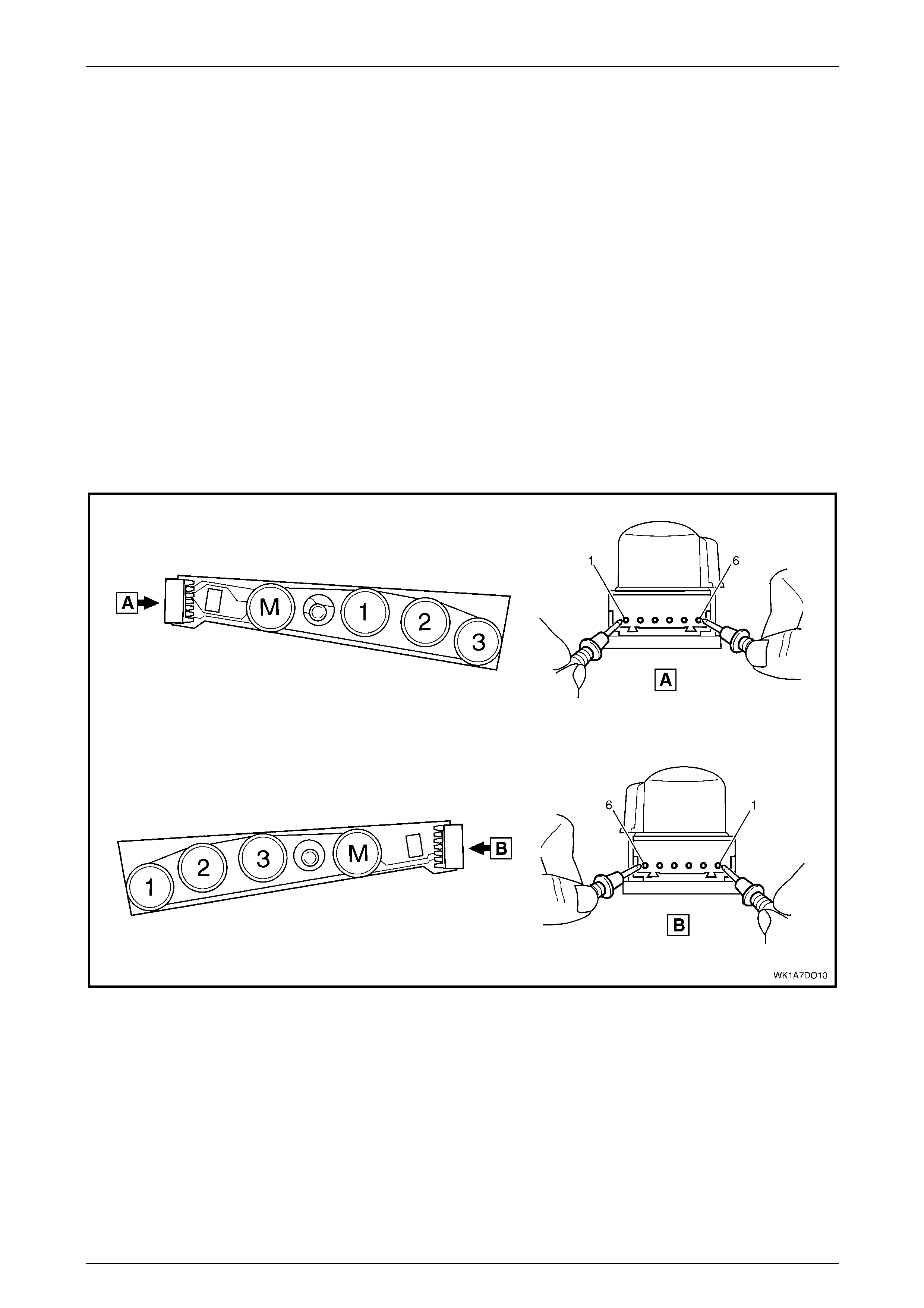
Seat Assemblies Page 1A7A–147
Page 1A7A–147
4.9 Memory Position Switch Test
The switch is located on the outer side of the seat, attached to the inner side of the front seat outer side cover.
Remove
To remove the memory position switch, refer to 5.4 Front Seat Outer Side Cover Assembly.
Reinstall
To reinstall the memory position switch, refer to 5.4 Front Seat Outer Side Cover Assembly.
Test
1 Place the switch in the positions as detailed i n the chart in this Section. Place the probes of the digital multimeter
onto the terminals listed and take the readin g. Compare the reading to the chart.
2 When testing the LED, ensure multimeter is set to diode range and n ote p olarity of probes.
3 If the switch fails any part of the test, replace the switch assembly with a serviceabl e item.
Figure 1A7A – 21

Seat Assemblies Page 1A7A–148
Page 1A7A–148
Right-hand Seat Memory Position Switch
Switch Depressed Switch Terminals Indication if Switch is Serviceable
------------ 6 and 1, 2, 3 and 4 Open circuit
Button 1 6 and 1 Continuity
Button 2 6 and 2 Continuity
Button 3 6 and 3 Continuity
Button M 6 and 4 Continuity
------------ 5 (+) probe and 6 (–) probe LED illuminated
Left-hand Seat Memory Position Switch
Switch Depressed Switch Terminals Indication if Switch is Serviceable
------------ 1 and 3, 4, 5 and 6 Open circuit
Button 1 1 and 6 Continuity
Button 2 1 and 5 Continuity
Button 3 1 and 4 Continuity
Button M 1 and 3 Continuity
------------ 2 (+) probe and 1 (–) probe LED illuminated
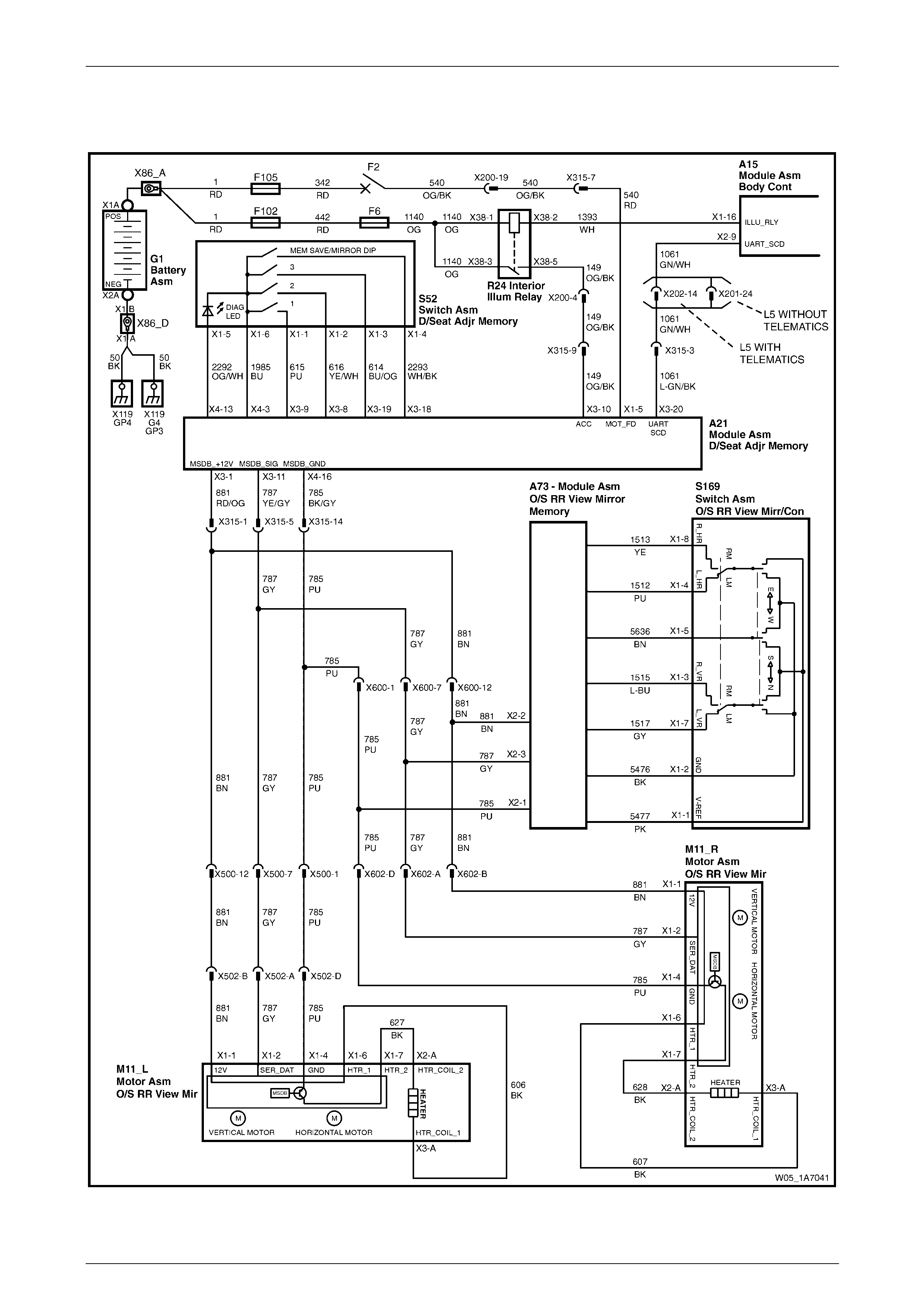
Seat Assemblies Page 1A7A–149
Page 1A7A–149
4.10 Electrical Diagnosis – Rear-view Mirrors
Wiring Diagram – Rear-view Mirrors, RHD
Figure 1A7A – 22
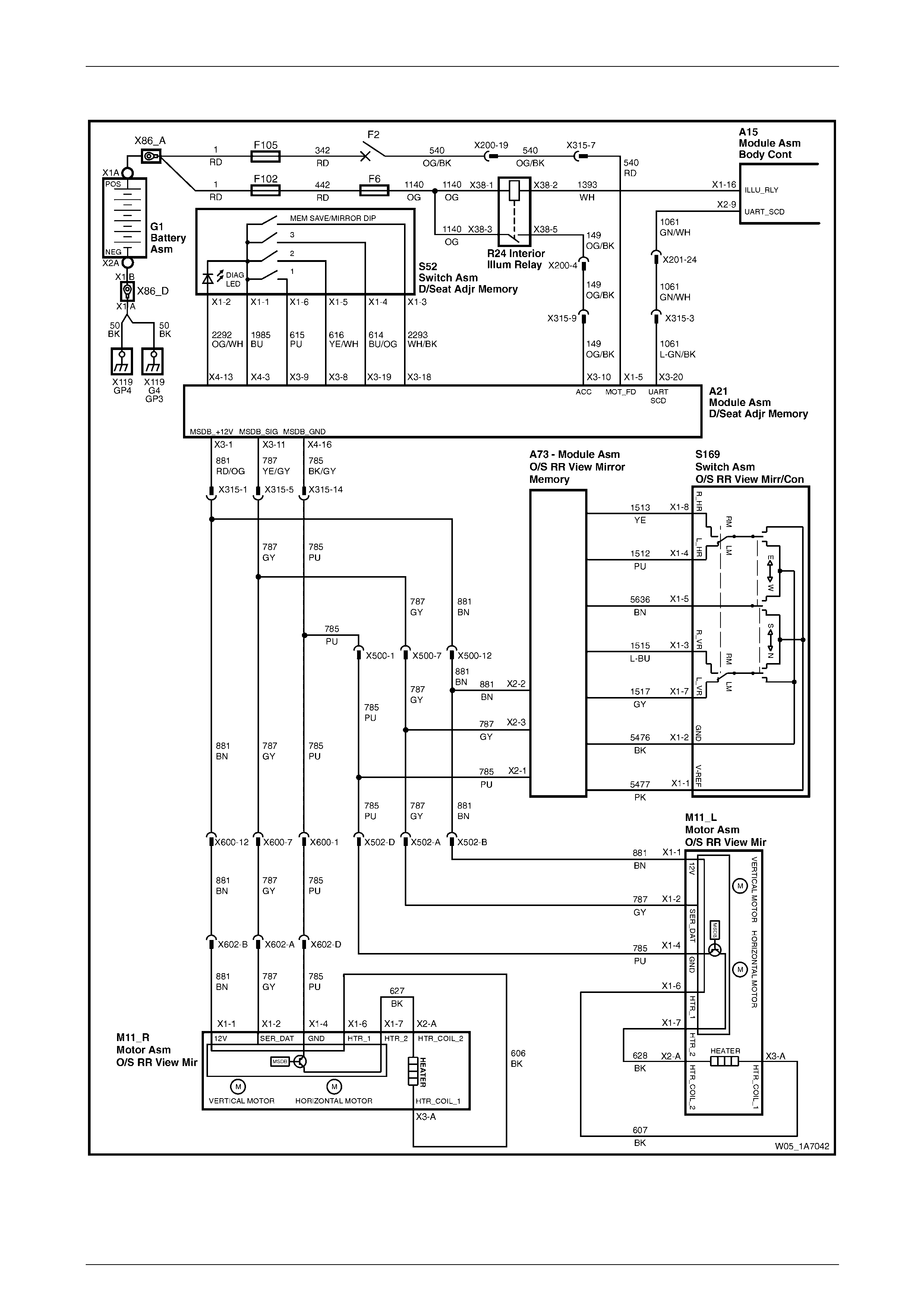
Seat Assemblies Page 1A7A–150
Page 1A7A–150
Wiring Diagram – Rear-view Mirrors, LHD
Figure 1A7A – 23
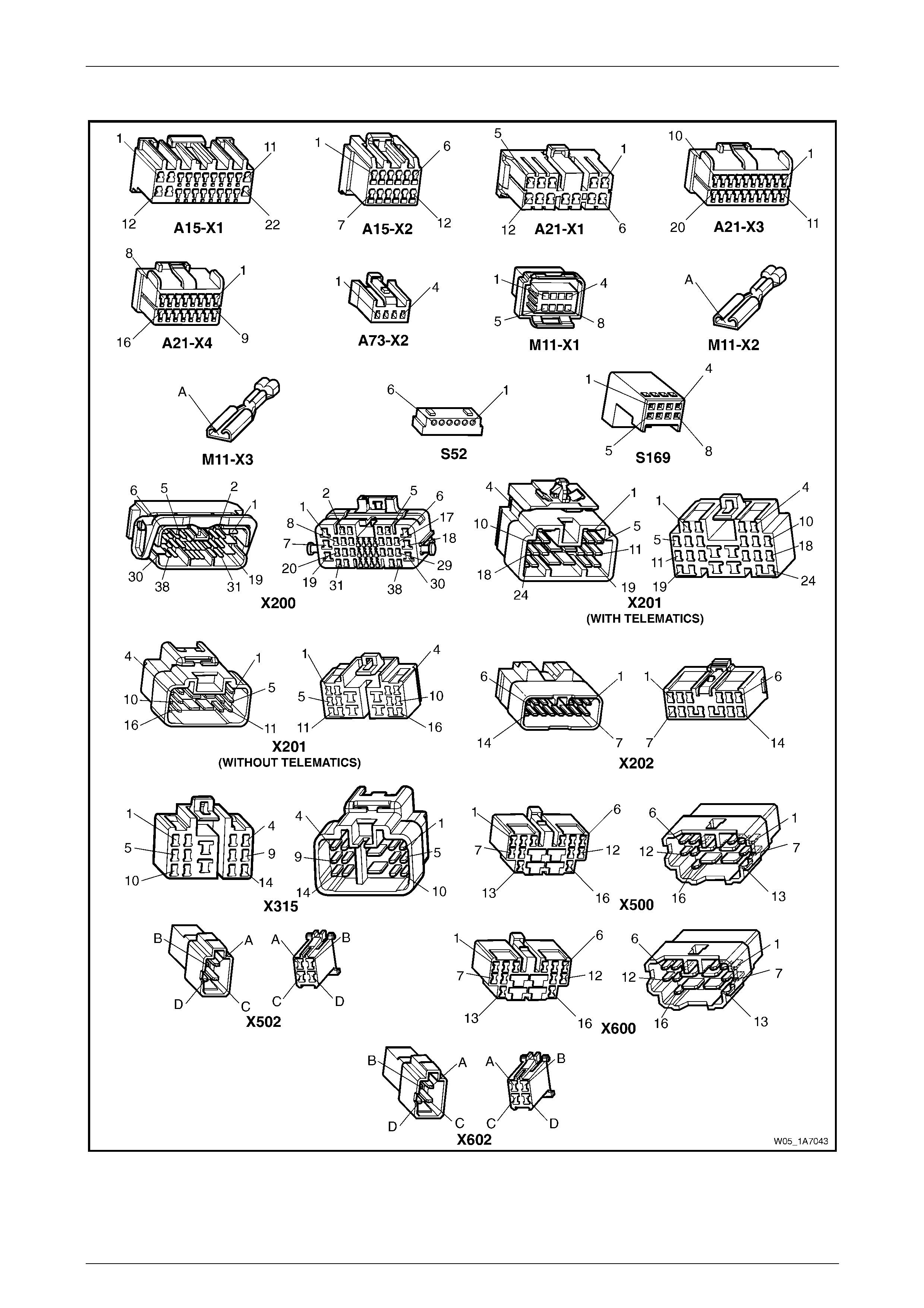
Seat Assemblies Page 1A7A–151
Page 1A7A–151
Connector Chart – Rear-view Mirrors
Figure 1A7A – 24

Seat Assemblies Page 1A7A–152
Page 1A7A–152
Initial Check
Introduction
This operational check uses Tech 2 to test the functionality of the exterior rear-view mirrors and iso lates which system is
faulty. The seat memory module provides electrical power, ground and serial data communications to the mirrors. As
described in 1 General Information, the mirrors can be controlle d:
• manually by the mirror control switch located on the driver's door,
• by pressing any of the memory buttons on the memor y pos ition switch, and
• to dip when reversing (passenger’s mirror o nly).
Refer to 1 General Information for further details on the operation of the exterior rear-vie w mirror.
Refer to Wiring Diagram – Rear-view Mirrors, RHD, Wiring Diagram – Rear-view Mirrors, LHD and
Connector Chart – Rear-view Mirrors to aid in diagnosing the exterior rear-view mirrors and associated components.
Test Description
The following numbers refer to the steps in the diagnostic table:
1 Checks if Tech 2 can communicate with the seat memory module.
2 Checks for existence of any diagnostic trouble codes.
3 Checks whether Tech 2 is receiving serial d ata from the exterior rear-view mirrors and the mirror control switch via
the rear-view mirror. All serial data communications need to be interrupted to these assemblies i n order for Tech 2
to indicate there is a problem.
4 Checks if serial data is being received at right exterior mirror only.
5 Checks if serial data is being received at left exterior mirror only.
6-9 Checks if the mirror control switch is serviceabl e. Isolates if the exterior rear-view mirrors and circuits are
serviceable.
10 Checks if the mirror dip function is serviceable.
11 Checks if the mirror heating function is serviceable.
12 Checks if the memory recall function of the exterior rear-view mirrors is serviceable. This function is controlled by
the seat memory module which transmits a signal throu gh the serial bus to inform the mirrors what position they
should be in. The exterior rear-view mirror assemblies store the physical position within their own modules. If the
seat aspect of this feature is operational, the exterior rear-view mirror assembly is faulty and must be replaced.

Seat Assemblies Page 1A7A–153
Page 1A7A–153
Diagnostic Table
Step Action Yes No
1 1 Connect Tech 2 to the DLC.
2 On Tech 2 select:
Body / Seat and Exterior Mirror Memory Module.
3 Turn the ignition switch on.
Does the System Identification Screen displa y system information? Go to Step 2 The seat memory
module is at fault
2 On Tech 2 select:
Body / Seat and Exterior Mirror Memory Module / Diagnostic
Trouble Codes / Read DTC Information.
Are there any diagnostic trou ble codes displayed? Go to appropriate
DTC table Go to Step 3
3 1 On Tech 2 select:
Body / Seat and Exterior Mirror Memory Module /
Diagnostic Data Display / Inputs And Outputs.
2 Scroll to Button Pack Communication.
Does Tech 2 display Okay? Go to Step 4
Refer to No Serial
Data from Exterior
Rear-view Mirrors
in this Section
4 On Tech 2 select:
Right Exterior Mirror Communication.
Does Tech 2 display Okay?
Go to Step 5
Refer to No Serial
Data – Right-hand
Exterior Rear-view
Mirror in this
Section
5 On Tech 2 select:
Left Exterior Mirror Communication.
Does Tech 2 display Okay?
Go to Step 6
Refer to No Serial
Data – Left-hand
Exterior Rear-view
Mirror in this
Section
6 1 On Tech 2 select:
Body / Seat and Exterior Mirror Memory Module /
Diagnostic Data Display / Input and Output.
2 Scroll to Right Exterior Mirror Switch.
3 Monitor Tech 2.
4 Move the rocker switch on the rear-view mirror switch to the
position to control the right ext erior mirror.
5 Using the rear-view mirror switch:
• Press the mirror up switch.
• Press the mirror down switch.
• Press the mirror left switch.
• Press the mirror right switch.
Does Tech 2 display Up, Down , Left, then Right during operation? Go to Step 7
Refer to Mirror
Control Switch
Inoperative in this
Section
7 During the test in Step 6, does the right-hand exterior rear-view mirror
move in the following directions?
• When the switch is in the neutral position, the mirror does not
move.
• When the switch is in the up position, the mirror moves up.
• When the switch is in the down position, the mirror moves
down.
• When the switch is in the right position, the mirror moves righ t.
• When the switch is in the left position, the mirror moves left.
NOTE
Ensure that the mirror is not at its maximum limit of travel
in any direction when performing this test. Go to Step 8
Replace the
right-hand exterior
rear-view mirror
assembly, refer to
Section 12H Rear-
view Mirrors

Seat Assemblies Page 1A7A–154
Page 1A7A–154
Step Action Yes No
8 1 On Tech 2 select:
Left Exterior Mirror Switch.
2 Monitor Tech 2.
3 Move the rocker switch on the rear-view mirror switch to the
position to control the left exterior mirror.
4 Using the rear-view mirror switch:
• Press the mirror up switch.
• Press the mirror down switch.
• Press the mirror left switch.
• Press the mirror right switch.
Does Tech 2 display Up, Down, Left, then Right during operation? Go to Step 9
Refer to Mirror
Control Switch
Inoperative in this
Section
9 During the test in Step 8, does the left-hand exterior rear-vie w mirror
move in the following directions?
• When the switch is in the neutral position, the mirror does not
move.
• When the switch is in the up position, the mirror moves up.
• When the switch is in the down position, the mirror moves
down.
• When the switch is in the right position, the mirror moves righ t.
• When the switch is in the left position, the mirror moves left.
NOTE
Ensure that the mirror is not at its maximum limit of travel
in any direction when performing this test. Go to Step 10
Replace the
left-hand exterior
rear-view mirror
assembly, refer to
Section 12H Rear-
view Mirrors
10 Does the mirror dip function operate correctly? Refer to Mirror Dip
Function Check in
this Section Go to Step 11
11 Does the mirror heating function operate correctly? Refer to Mirror
Heating Function
Check in this
Section Go to Step 12
12 Does the memory recall function of the exterior rear-view mirrors
operate correctly? If both exterior
rear-view mirrors
are unable to recall
memory positions,
check the
functionality of the
seat, refer to Initial
Check in 4.8
Electrical Diagnosis
– Memory Seat.
If only one mirror is
unable to recall
memory positions,
replace the mirror
assembly, refer to
Section 12H Rear-
view Mirrors System serviceable
When all diagno sis an d repairs are completed, clear all DT Cs and check the system fo r correct operation.

Seat Assemblies Page 1A7A–155
Page 1A7A–155
Mirror Dip Function Check
Introduction
The mirror dip function is operational when:
• the mirror dip function is enabled, refer to 1 General Information for details,
• a position for the passenger's exterior rear-view mirror is stored as the mirror dip, and
• the transmission selector must be placed in REVERSE position.
Test Description
The following numbers refer to the steps in the diagnostic table:
2 Checks if the mirror DIP function is enabled.
3 Checks if the mirror DIP function operates and is positioned correctly.
4 Checks if the mirror DIP function returns an Active message on Tech 2 when the transmission selector is placed in
REVERSE position. Isolates whether there is a fault with the seat memory module or with the serial data from the
transmission selector.
Diagnostic Table
Step Action Yes No
1 Has the Initial Check been performed?
Go to Step 2
Perform the Initial
Check in this
Section
2 1 On Tech 2 select:
Body / Seat and Exterior Mirror Memory Module /
Diagnostic Data Display / Memory.
2 Scroll to Priority 1.
Does Tech 2 display Mirror Dip Button as Enabled? Go to Step 3
Enable mirror DIP
function, refer to 1
General
Information.
Go to Step 3
3 1 Ensure the stored mirror DIP position is noticeably different
from the standard position of the left exterior mirror, refer to 1
General Information.
2 Check the mirror DIP function by placing the transmission
selector in reverse.
Does the mirror DIP function operate? System serviceable Go to Step 4
4 1 On Tech 2 select:
Body / Seat and Exterior Mirror Memory Module /
Diagnostic Data Display / Inputs and Outputs.
2 Scroll to Reverse Gear.
Does Tech 2 display Reverse Gear as Active?
Replace the seat
memory module,
refer to 5.12 Seat
Cable Tray and
Memory Module
Refer to 6C3
Powertrain
Management for V8
or
6C2 Powertrain
Management for V6
When all diagno sis an d repairs are completed, clear all DT Cs and check the system fo r correct operation.
Seat Assemblies Page 1A7A–156
Page 1A7A–156
Mirror Heating Function Check
Introduction
When the demist button on the instrument panel is pressed to activate the demist function, the request is sent via the
serial data bus to the exterior rear-view mirror assemblies.
Test Description
The following numbers refer to the steps in the diagnostic table:
2 Checks if Tech 2 confirms the demist function has been activated.
3 Checks if the heater element in the right-hand e xterior rear-view mirror operates when the ignition and rear window
demister are switched on.
4 Checks if the right-hand mirror heater element is servicea bl e. Isolates whether the heater element or the exterior
rear-view mirror assembly is at fault.
5 Checks if the heater element in the left-hand exterior rear-view mirror operates when the ignition and rear window
demister are switched on.
6 Checks if the left-hand mirror heater element is serviceable. Isolates whether the heater element or the exterior
rear-view mirror assembly is at fault.
Diagnostic Table
Step Action Yes No
1 Has the Initial Check been performed?
Go to Step 2
Perform the Initial
Check in this
Section
2 1 On Tech 2 select:
Body / Seat and Exterior Mirror Memory Module /
Diagnostic Data Display / Inputs and Outputs.
2 Scroll to Demist Request.
3 Turn on the rear window demister.
Does Tech 2 display Demist Req uest as Yes? Go to Step 3
Refer to 12J Body
Control Module.
Go to Step 3
3 Operate the rear window demister for 2 – 3 minutes.
Does the right-hand exterior mirror feel warm? Go to Step 5 Go to Step 4
4
Turn off the rear window demister before removing
and replacing the righ t-hand exterior mirror glass.
Test the heater element of the right-hand ext erior re ar-view mirror,
refer to Section 12H Rear-view Mirrors.
Is the heater element serviceable?
Replace the
right-hand exterior
rear-view mirror
assembly, refer to
Section 12H Rear-
view Mirrors
Replace the
right-hand exterior
rear-view mirror
glass, refer to
Section 12H Rear-
view Mirrors.
Go to Step 5
5 Operate the rear window demister for 2 – 3 minutes.
Does the left-hand exterior mirror feel warm? System serviceable Go to Step 6
6
Turn off the rear window demister before removing
and replacing the left-hand exterior mirror glass.
Test the heater element of the left-hand exterior rear-view mirror,
refer to Section 12H Rear-view Mirrors.
Is the heater element serviceable?
Replace the
left-hand exterior
rear-view mirror
assembly, refer to
Section 12H Rear-
view Mirrors
Replace the
left-hand exterior
rear-view mirror
glass, refer to
Section 12H Rear-
view Mirrors
When all diagno sis an d repairs are completed, clear all DT Cs and check the system fo r correct operation.

Seat Assemblies Page 1A7A–157
Page 1A7A–157
No Serial Data from Exterior Rear-view Mirrors
Introduction
The exterior rear-view mirrors have a common power, ground and serial data connector at the seat memory module. If
the circuit is followed, there are two splices in each of the po wer, grou nd and data communication circuits. In this test, as
there are not serial data communications with any of the exterior rear-view mirrors, it is assumed that the fault will be in a
location common to all circuits.
Refer to Wiring Diagram – Rear-view Mirrors, RHD, Wiring Diagram – Rear-view Mirrors, LHD and
Connector Chart – Rear-view Mirrors to aid in diagnosing the exterior rear-view mirrors and associated components.
Test Description
The following numbers refer to the steps in the diagnostic table:
2 Checks if the connectors which are common to the serial data communication for the exterior rear-vie w mirrors are
secure.
3 Checks if battery voltage is present for the exterior rear-view mirror system at the seat memory module.
4 Checks if the seat memory module is supplying a ground circuit for the exterior rear-view mirror system.
5 Checks the battery supply circuit for a short to ground.
6 Checks the ground circuit for a short to battery.
7 Checks if there is continuity in the serial data circuit between connectors A21 – X3 pin 11 and X500 pin 7. Isolates
whether there is an open circuit in circuit 787 that will affect both the exterior rear-view mirrors or the seat memory
module is faulty.
Diagnostic Table Notes
1 For all wiring harness fault diagnoses, refer to Section 12P Wiring Diagram s.
2 For wiring harness repairs, refer to Section 12P Wiring Diagrams.
3 Refer to Section 12O Fuses, Relays and Wiring Harnesses for harness routeing.
4 If the fault is deemed to be intermittent, refer to Section 12P Wiring Diagrams.

Seat Assemblies Page 1A7A–158
Page 1A7A–158
Diagnostic Table
Step Action Yes No
1 Has the Initial Check been performed?
Go to Step 2
Perform the Initial
Check in this
Section
2 Ensure the following connectors are secure (refer to Note 3)?
• A21 – X3
• A21 – X4
• X315 Go to Step 3 Secure the relevant
connectors
3 1 Disconnect connectors A21 – X3 and A21 – X4 from the seat
memory module.
2 Using a multimeter set to measure voltage, probe between seat
memory module A21 – X3 pin 1 and a known ground (refer to
Note 1).
Does the multimeter indicate batter y voltage? Go to Step 4
Replace the seat
memory module,
refer to 5.12 Seat
Cable Tray and
Memory Module
4 Using a multimeter set to measure resistance, probe between seat
memory module A21 – X4 pin 16 and a known ground (refer to Note
1).
Does the multimeter indicate continuity? Go to Step 5
Replace the seat
memory module,
refer to 5.12 Seat
Cable Tray and
Memory Module
5 Using a multimeter set to measure resistance, probe between
connector A21 – X3 pin 1 and a known ground (refer to Note 1).
Does the multimeter indicate continuity?
Repair or replace
circuit 881 (refer to
Note 2) Go to Step 6
6 Using a multimeter set to measure voltage, probe between connector
A21 – X4 pin 16 and a known ground (refer to Note 1).
Does the multimeter indicate batter y voltage ?
Repair or replace
circuit 785 (refer to
Note 2) Go to Step 7
7 Using a multimeter set to measure resistance, probe between
connectors A21 – X3 pin 11 and X500 pin 7 (refer to Note 1).
Does the multimeter indicate continuity? Replace the seat
memory module,
refer to 5.12 Seat
Cable Tray and
Memory Module
Repair or replace
circuit 787 between
connector
A21 – X3 pin 11
and the first splice
on circuit 787 (refer
to Note 2)
When all diagno sis an d repairs are completed, clear all DT Cs and check the system fo r correct operation.

Seat Assemblies Page 1A7A–159
Page 1A7A–159
No Serial Data – Right-hand Exterior Rear-view Mirror
Introduction
Refer to Wiring Diagram – Rear-view Mirrors, RHD, Wiring Diagram – Rear-view Mirrors, LHD and
Connector Chart – Rear-view Mirrors to aid in diagnosing the exterior rear-view mirrors and associated components.
Test Description
The following numbers refer to the steps in the diagnostic table:
2 Checks if there is battery voltage supplied to the right-hand exterior rear-view mirror. Isolates if there is a fault in
circuit 881 between connecto rs X602 and A21 – X3.
3 Checks if the ground circuit for the right-hand exterior rear-view mirror is serviceable. Isolates if there is a fault in
circuit 785 between connecto rs X602 and A21 – X4.
4 Checks the serial data circuit for the right-hand exterior rear-view mirror for integrity. Isolates whether there is a
fault in circuit 787 between connectors A21 – X3 and X602 or the right-hand exterior rear-view mirror assembly is
faulty.
Diagnostic Table Notes
1 For all wiring harness fault diagnoses, refer to Section 12P Wiring Diagram s.
2 For wiring harness repairs, refer to Section 12P Wiring Diagrams.
3 Refer to Section 12O Fuses, Relays and Wiring Harnesses for harness routeing.
4 If the fault is deemed to be intermittent, refer to Section 12P Wiring Diagrams.
Diagnostic Table
Step Action Yes No
1 Has the Initial Check been performed?
Go to Step 2
Perform the Initial
Check in this
Section
2 Backprobe connector X602 pin B with a test lamp (refer to Note 1).
Does the test lamp illuminate?
Go to Step 3
Repair or replace
circuit 881 between
connectors X602
and A21 – X3 (refer
to Note 2)
3 1 Disconnect harness connector X602.
2 Using a multimeter set to measure resistance, probe between
connector X602 pin D and a known ground (refer to Note 1).
Does the multimeter indicate continuity? Go to Step 4
Repair or replace
circuit 785 between
connectors X602
and A21 – X4 (refer
to Note 2)
4 1 Disconnect connector A21 – X3 from the seat memory module.
2 Using a multimeter set to measure resistance, probe between
connectors A21 – X3 pin 11 and X602 pin A (refer to Note 1).
Does the multimeter indicate continuity?
Replace the
right-hand exterior
rear-view mirror
assembly, refer to
Section 12H Rear-
view Mirrors
Repair or replace
circuit 787 between
connectors
A21 – X3 and X602
(refer to Note 2)
When all diagno sis an d repairs are completed, clear all DT Cs and check the system fo r correct operation.

Seat Assemblies Page 1A7A–160
Page 1A7A–160
No Serial Data – Left-hand Exterior Rear-view Mirror
Introduction
Refer to Wiring Diagram – Rear-view Mirrors, RHD, Wiring Diagram – Rear-view Mirrors, LHD and
Connector Chart – Rear-view Mirrors to aid in diagnosing the exterior rear-view mirrors and associated components.
Test Description
The following numbers refer to the steps in the diagnostic table:
2 Checks if there is battery voltage supplied to the left-hand exterior rear-view mirror. Isolates if there is a fault in
circuit 881 between connecto rs X502 and A21 – X3.
3 Checks if the ground circuit for the left-hand exterior rear-view mirror is serviceable. Isolates if there is a fault in
circuit 785 between connecto rs X502 and A21 – X4.
4 Checks the serial data circuit for the left-hand exterior rear-view mirror for integrity. Isolates whether there is a fault
in circuit 787 between connectors A21 – X3 and X502 or the left-hand exterior rear-view mirror assembly is faulty.
Diagnostic Table Notes
1 For all wiring harness fault diagnoses, refer to Section 12P Wiring Diagram s.
2 For wiring harness repairs, refer to Section 12P Wiring Diagrams.
3 Refer to Section 12O Fuses, Relays and Wiring Harnesses for harness routeing.
4 If the fault is deemed to be intermittent, refer to Section 12P Wiring Diagrams.
Diagnostic Table
Step Action Yes No
1 Has the Initial Check been performed?
Go to Step 2
Perform the Initial
Check in this
Section
2 Backprobe connector X502 pin B with a test lamp (refer to Note 1).
Does the test lamp illuminate?
Go to Step 3
Repair or replace
circuit 881 between
connectors X502
and A21 – X3 (refer
to Note 2)
3 1 Disconnect harness connector X502.
2 Using a multimeter set to measure resistance, probe between
connector X502 pin D and a known ground (refer to Note 1).
Does the multimeter indicate continuity? Go to Step 4
Repair or replace
circuit 785 between
connectors X502
and A21 – X4 (refer
to Note 2)
4 1 Disconnect connector A21 – X3 from the seat memory module.
2 Using a multimeter set to measure resistance, probe between
connectors A21 – X3 pin 11 and X502 pin A (refer to Note 1).
Does the multimeter indicate continuity?
Replace the
left-hand exterior
rear-view mirror
assembly, refer to
Section 12H Rear-
view Mirrors
Repair or replace
circuit 787 between
connectors
A21 – X3 and X502
(refer to Note 2)
When all diagno sis an d repairs are completed, clear all DT Cs and check the system fo r correct operation.

Seat Assemblies Page 1A7A–161
Page 1A7A–161
Mirror Control Switch Inoperative
Introduction
When the mirror control switch is used, the signal that it generates is converted by the rear-view mirror module to serial
data. It is then transmitted over the serial data bus. The exterior rear-vie w mirrors then receive this serial data and move
the appropriate exterior rear-view mirror in the direction that was requested by the mirror control switch.
Refer to Wiring Diagram – Rear-view Mirrors, RHD, Wiring Diagram – Rear-view Mirrors, LHD and
Connector Chart – Rear-view Mirrors to aid in diagnosing the exterior rear-view mirrors and associated components.
Test Description
The following numbers refer to the steps in the diagnostic table:
2 Checks if the mirror control switch is serviceable.
3 Checks if there is battery power to the rear-view mirror module. Isolates if there is a fault in circuit 881 between
connectors A73 – X2 and A21 – X3.
4 Checks if there is battery power to the mirror control switch. Isolates if the rear-view mirror modul e is at fault.
5 Checks if the ground circuit for the rear-view mirror module i s serviceable. Isolates if there is a fault in circuit 785
between connectors A73 – X2 and A21 – X4.
6 Checks if the ground circuit for the mirror control switch is serviceable. Isolates if the rear-view mirror module is at
fault.
7 Checks if there is continuity on the serial data bus between connectors A73 – X2 and A21 – X3. Isolates whether
there is an open circuit in circuit 787 between connectors A73 – X2 and A21 – X3 or the rear-vie w mem ory module
is faulty.
Diagnostic Table Notes
1 For all wiring harness fault diagnoses, refer to Section 12P Wiring Diagram s.
2 For wiring harness repairs, refer to Section 12P Wiring Diagrams.
3 Refer to Section 12O Fuses, Relays and Wiring Harnesses for harness routeing.
4 If the fault is deemed to be intermittent, refer to Section 12P Wiring Diagrams.

Seat Assemblies Page 1A7A–162
Page 1A7A–162
Diagnostic Table
Step Action Yes No
1 Has the Initial Check been performed?
Go to Step 2
Perform the Initial
Check in this
Section
2 Test the mirror control switch, refer to Section 12H Rear-view Mirrors.
Is the mirror control switch serviceable? Go to Step 3
Replace the mirror
control switch, refer
to Section 12H
Rear-view Mirrors
3 Backprobe connector A73 – X2 pin 2 with a test lamp (refer to
Note 1).
Does the test lamp illuminate?
Go to Step 4
Repair or replace
circuit 881 between
connectors
A73 – X2 and
A21 – X3 (refer to
Note 2)
4 Backprobe connector S169 – X1 pin 1 with a test lamp (refer to
Note 1).
Does the test lamp illuminate?
Go to Step 5
Replace the
rear-view mirror
module, refer to
Section 1A5 Front
and Rear Door
Assemblies
5 Using a multimeter set to measure resistance, probe between
connector A73 – X2 pin 1 and a known ground (refer to Note 1).
Does the multimeter indicate continuity?
Go to Step 6
Repair or replace
circuit 785 between
connectors
A73 – X2 and
A21 – X4 (refer to
Note 2)
6 Using a multimeter set to measure resistance, probe between
connector S169 – X1 pin 2 and a known ground (refer to Note 1).
Does the multimeter indicate continuity?
Go to Step 7
Replace the
rear-view mirror
module, refer to
Section 1A5 Front
and Rear Door
Assemblies
7 1 Disconnect connectors A21 – X3 from the seat memory module
and A73 – X2 from the rear-vie w mirror module.
2 Using a multimeter set to measure resistance, probe between
connectors A73 –X2 pin 3 and a A21 – X3 pin 11 (refer to Note
1).
Does the multimeter indicate continuity?
Replace the
rear-view mirror
module, refer to
Section 1A5 Front
and Rear Door
Assemblies
Repair or replace
circuit 787 between
connectors
A73 – X2 and
A21 – X3 (refer to
Note 2)
When all diagno sis an d repairs are completed, clear all DT Cs and check the system fo r correct operation.
Seat Assemblies Page 1A7A–163
Page 1A7A–163
5 Service Operations – Front Seat
5.1 Usage Chart
How To Use This Chart
The following usage chart is provided to help determine the seat type fitted to the vehicle. This is important prior to
repairs being performed as the failed/damaged part may no t be serviced.
To determine the seat type fitted to the vehicle, obtain the vehicl e model, which seat requires attention and the seat
cover fabric. Establish other features of the seat such as th e electric movement functions. Using the chart will lead to the
elimination of all other seat combinations, al lowing for the identification of the type and the construction of the seat.
Refer to the Figure number shown in Front Seat Type column for a component break down of the front seat assembly.
1 Vehicle – Vehicle model identification.
2 Seating – Driver front seat or passenger front seat.
3 Fabric – Cloth or leather seat covers.
4 Movement – Indicates the number of electric movement functions of the seat:
• Four-way – Seat cushion electric front and re ar raise/lower.
• Six-way – As four- way plus s eat cushion electric fore/aft movement.
• Eight-way – As six-way plus electric seat-back recline.
5 Memory – Indicates if a seat memory module is fitted.
6 SIAB – If the seat is fitted with a side impact airbag assembly.
7 Construction – Surebond refers to the seat cover being glued to the seat pad. This type i s serviced as a pad and
cover assembly only. Hook and Loop refers to the seat cover being attached to the seat pad with a Velcro type
material and both being servi ced as separate parts.
8 Head Restraint – Indicates whether fixed or active head res t raints are fitted.
9 Front Seat Type – Identifies the seat type and provides reference to illustrations which show a breakdown of the
serviced component for each front seat assembly.
Domestic
Vehicle Seating Fabric Movement Memory SIAB Construction Head
Restraint Front Seat Type
(refer to)
Driver Cloth/
Leather Eight- way No Yes Hook & Loop Active 1
(Figure 1A7A – 25)
Statesman
– Level 4
Passenger Cloth/
Leather Eight -way No Yes Hook & Loop Active 2
(Figure 1A7A – 26)
Driver Leather Eight- way Yes Yes Hook & Loop Active 3
(Figure 1A7A – 27)
Caprice
– Level 5
Passenger Leather Eight-way No Yes Hook & Loop Active 4
(Figure 1A7A – 28)

Seat Assemblies Page 1A7A–164
Page 1A7A–164
Gulf States
Vehicle Seating Fabric Movement Memory SIAB Construction Head
Restraint Front Seat Type
(refer to)
Driver Cloth Six-way No No Surebond Fixed 5
(Figure 1A7A – 29)
Passenger Cloth Four-way No No Surebond Fixed 6
(Figure 1A7A – 30)
Driver Cloth Eight-way No No Surebond Fixed 7
(Figure 1A7A – 31)
Caprice LS
– Level 1
Passenger Cloth Eight-way No No Surebond Fixed 8
(Figure 1A7A – 32)
Driver Cloth/
Leather Eight- way No Yes Hook & Loop Fixed 9
(Figure 1A7A – 33)
Caprice
LTZ
– Level 2 Passenger Cloth/
Leather Eight -way No Yes Hook & Loop Fixed 10
(Figure 1A7A – 34)
Driver Leather Eight- way No Yes Hook & Loop Fixed 11
(Figure 1A7A – 35)
Caprice SS
– Level 3
Passenger Leather Eight-way No Yes Hook & Loop Fixed 12
(Figure 1A7A – 36)
Driver Leather Eight- way Yes Yes Hook & Loop Active 13
(Figure 1A7A – 37)
Caprice
Royale
– Level 5 Passenger Leather Eight-way No Yes Hook & Loop Active 14
(Figure 1A7A – 38)
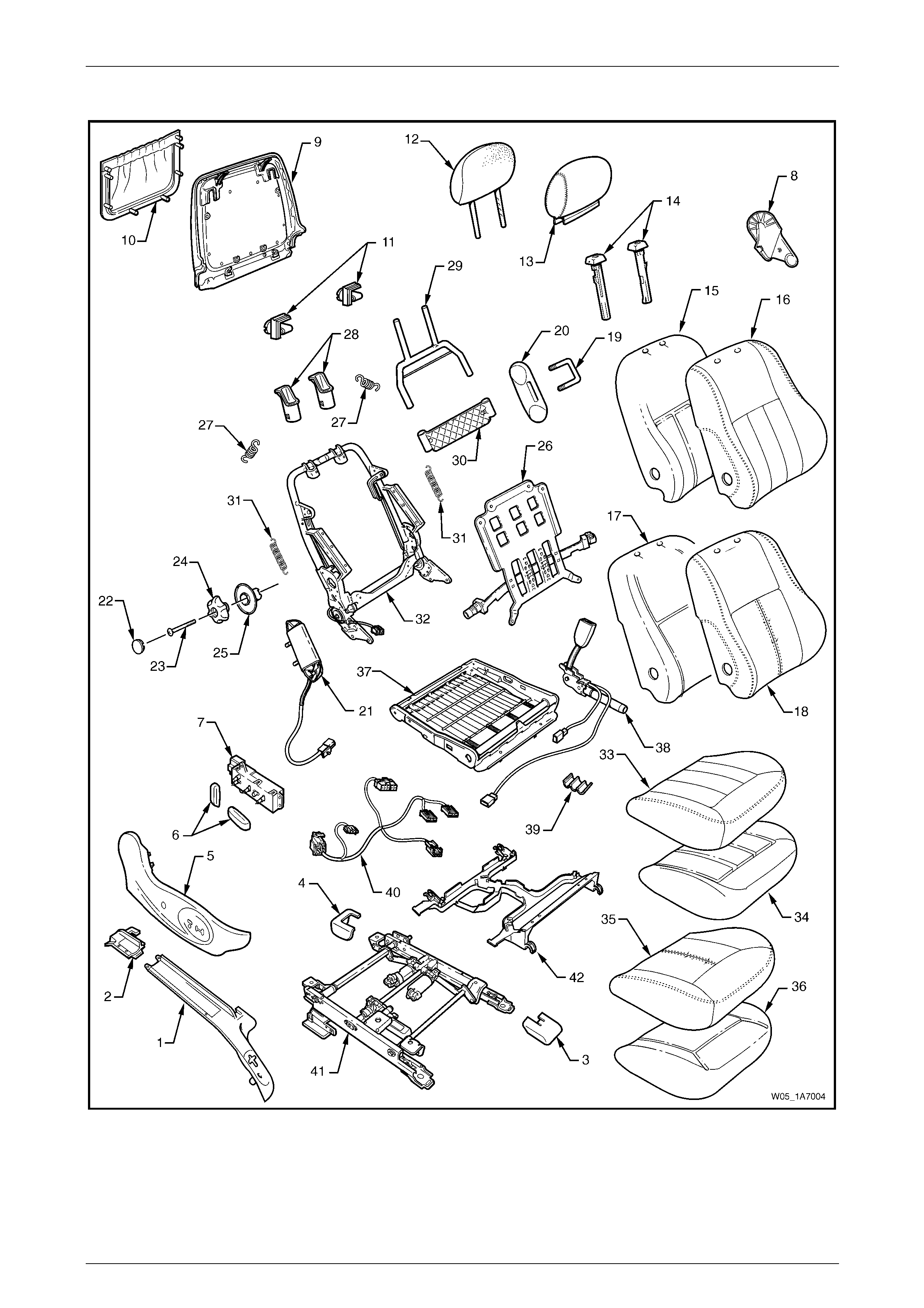
Seat Assemblies Page 1A7A–165
Page 1A7A–165
Front Seat Type 1
Figure 1A7A – 25

Seat Assemblies Page 1A7A–166
Page 1A7A–166
Legend
1 Front Seat Outer Front Cover
2 Front Seat Outer Rear Cover
3 Front Seat Inner Front Cover
4 Front Seat Inner Rear Cover
5 Front Seat Outer Side Cover
6 Front Seat Adjustment Switch Knobs
7 Front Seat Adjustment Switch – Eight-way
8 Front Seat Inner Side Cover
9 Front Seat-back Rear Cover
10 Front Seat-back Map Pocket
11 Front Seat-back Cover Retaining Clips
12 Front Seat Head Restraint Pad Assembly
13 Front Seat Head Restraint Cover
14 Front Seat Head Restraint Sleeves
15 Front Seat-back Pad – Cloth Cover
16 Front Seat-back Cloth Cover
17 Front Seat-back Pad – Leather Cover
18 Front Seat-back Leather Cover
19 Front Seat Dummy Block U-bolt
20 Front Seat Dummy Block Insert
21 Side Impact Airbag Assembly
22 Lumbar Support Knob Cover
23 Lumbar Support Knob Screw
24 Lumbar Support Knob
25 Lumbar Support Deflector Ring
26 Lumbar Support Assembly
27 Lumbar Support Retaining Spring
28 Active Head Restraint Frame Sleeves
29 Active Head Restraint Frame Assembly
30 Active Head Restraint Frame Support Strap
31 Active Head Restraint Frame Retaining Spring
32 Front Seat-back Frame Assembly
33 Front Seat Cushion Cloth Cover
34 Front Seat Cushion Pad – Cloth Cover
35 Front Seat Cushion Leather Cover
36 Front Seat Cushion Pad – Leather Cover
37 Front Seat Cushion Frame Assembly
38 Seatbelt Buckle & Pretensioner Assembly
39 Wiring Harness Retaining Clip
40 Wiring Harness Assembly
41 Track and Height Adjust Assembly
42 Front Seat Cable Tray
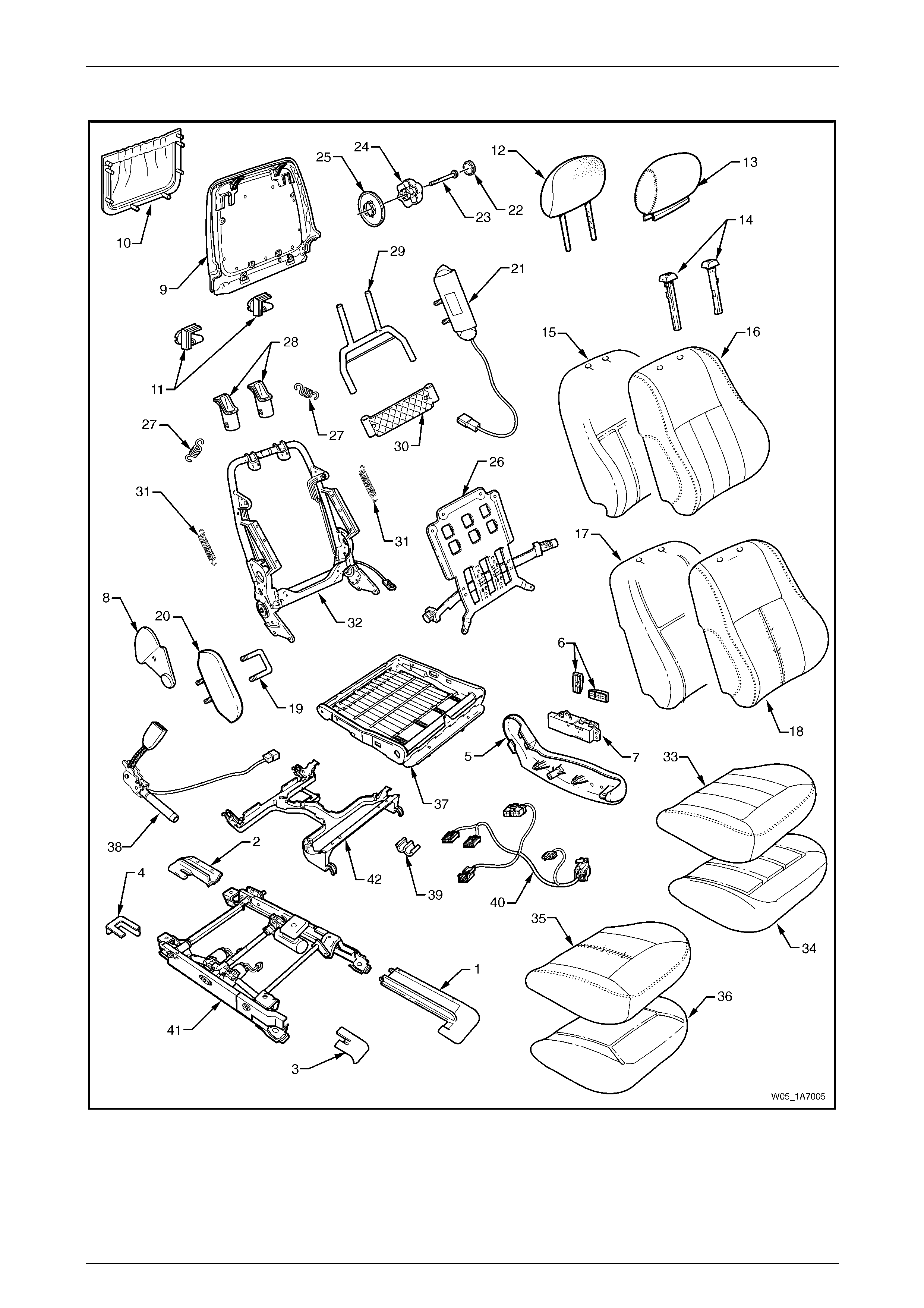
Seat Assemblies Page 1A7A–167
Page 1A7A–167
Front Seat Type 2
Figure 1A7A – 26

Seat Assemblies Page 1A7A–168
Page 1A7A–168
Legend
1 Front Seat Outer Front Cover
2 Front Seat Outer Rear Cover
3 Front Seat Inner Front Cover
4 Front Seat Inner Rear Cover
5 Front Seat Outer Side Cover
6 Front Seat Adjustment Switch Knobs
7 Front Seat Adjustment Switch – Eight-way
8 Front Seat Inner Side Cover
9 Front Seat-back Rear Cover
10 Front Seat-back Map Pocket
11 Front Seat-back Cover Retaining Clips
12 Front Seat Head Restraint Pad Assembly
13 Front Seat Head Restraint Cover
14 Front Seat Head Restraint Sleeves
15 Front Seat-back Pad – Cloth Cover
16 Front Seat-back Cloth Cover
17 Front Seat-back Pad – Leather Cover
18 Front Seat-back Leather Cover
19 Front Seat Dummy Block u-bolt
20 Front Seat Dummy Block Insert
21 Side Impact Airbag Assembly
22 Lumbar Support Knob Cover
23 Lumbar Support Knob Screw
24 Lumbar Support Knob
25 Lumbar Support Deflector Ring
26 Lumbar Support Assembly
27 Lumbar Support Retaining Spring
28 Active Head Restraint Frame Sleeves
29 Active Head Restraint Frame Assembly
30 Active Head Restraint Frame Support Strap
31 Active Head Restraint Frame Retaining Spring
32 Front Seat-back Frame Assembly
33 Front Seat Cushion Cloth Cover
34 Front Seat Cushion Pad – Cloth Cover
35 Front Seat Cushion Leather Cover
36 Front Seat Cushion Pad – Leather Cover
37 Front Seat Cushion Frame Assembly
38 Seatbelt Buckle & Pretensioner Assembly
39 Wiring Harness Retaining Clip
40 Wiring Harness Assembly
41 Track and Height Adjust Assembly
42 Front Seat Cable Tray
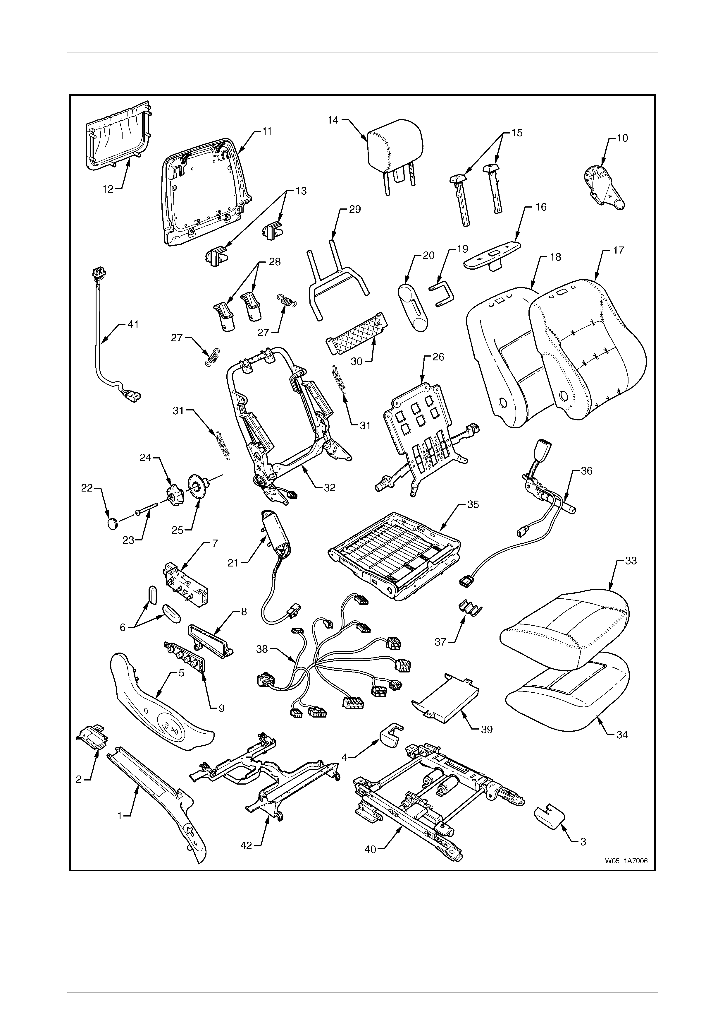
Seat Assemblies Page 1A7A–169
Page 1A7A–169
Front Seat Type 3
Figure 1A7A – 27

Seat Assemblies Page 1A7A–170
Page 1A7A–170
Legend
1 Front Seat Outer Front Cover
2 Front Seat Outer Rear Cover
3 Front Seat Inner Front Cover
4 Front Seat Inner Rear Cover
5 Front Seat Outer Side Cover
6 Front Seat Adjustment Switch Knobs
7 Front Seat Adjustment Switch – Eight-way
8 Memory Position Switch Cover
9 Memory Position Switch Assembly
10 Front Seat Inner Side Cover
11 Front Seat-back Rear Cover
12 Front Seat-back Map Pocket
13 Front Seat-back Cover Retaining Clips
14 Front Seat Head Restraint Assembly*
15 Front Seat Head Restraint Sleeves
16 Front Seat Head Restraint Guide Cover
17 Front Seat-back Cover
18 Front Seat-back Pad
19 Front Seat Dummy Block U-bolt
20 Front Seat Dummy Block Insert
21 Side Impact Airbag Assembly
22 Lumbar Support Knob Cover
23 Lumbar Support Knob Screw
24 Lumbar Support Knob
25 Lumbar Support Deflector Ring
26 Lumbar Support Assembly
27 Lumbar Support Retaining Spring
28 Active Head Restraint Frame Sleeves
29 Active Head Restraint Frame Assembly
30 Active Head Restraint Frame Support Strap
31 Active Head Restraint Frame Retaining Spring
32 Front Seat-back Frame Assembly
33 Front Seat Cushion Cover
34 Front Seat Cushion Pad
35 Front Seat Cushion Frame Assembly
36 Seatbelt Buckle & Pretensioner Assembly
37 Wiring Harness Retaining Clip
38 Wiring Harness Assembly
39 Seat Memory Module
40 Track and Height Adjust Assembly
41 Rear Seat Entertainment Lower Wiring Harness Assembly
42 Front Seat Cable Tray
* Refer to Figure 1A7A – 39 for the front head restraint assembly compone nts.
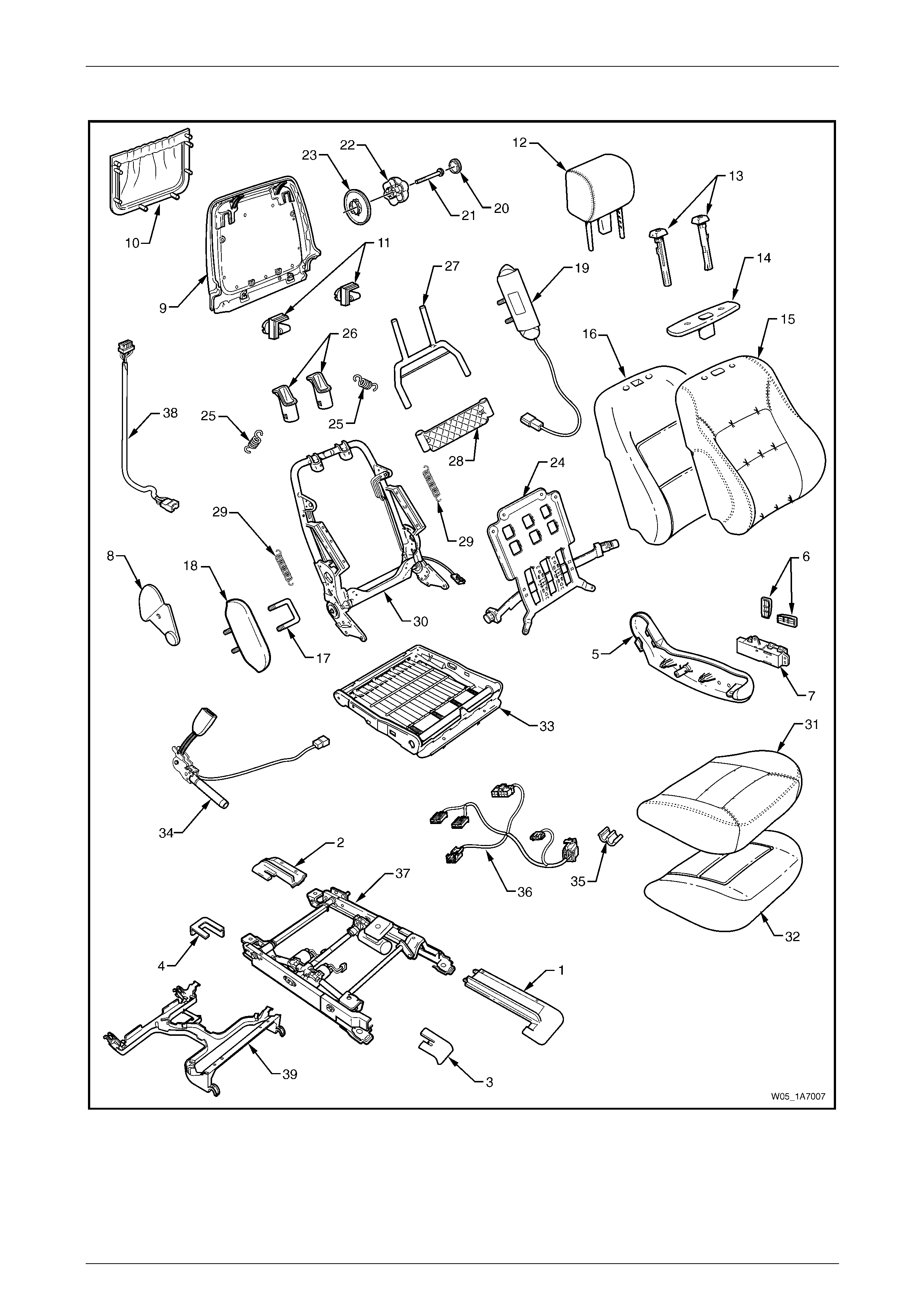
Seat Assemblies Page 1A7A–171
Page 1A7A–171
Front Seat Type 4
Figure 1A7A – 28

Seat Assemblies Page 1A7A–172
Page 1A7A–172
Legend
1 Front Seat Outer Front Cover
2 Front Seat Outer Rear Cover
3 Front Seat Inner Front Cover
4 Front Seat Inner Rear Cover
5 Front Seat Outer Side Cover
6 Front Seat Adjustment Switch Knobs
7 Front Seat Adjustment Switch – Eight-way
8 Front Seat Inner Side Cover
9 Front Seat-back Rear Cover
10 Front Seat-back Map Pocket
11 Front Seat-back Cover Retaining Clips
12 Front Seat Head Restraint Assembly*
13 Front Seat Head Restraint Sleeves
14 Front Seat Head Restraint Guide Cover
15 Front Seat-back Cover
16 Front Seat-back Pad Cover
17 Front Seat Dummy Block U-bolt
18 Front Seat Dummy Block Insert
19 Side Impact Airbag Assembly
20 Lumbar Support Knob Cover
21 Lumbar Support Knob Screw
22 Lumbar Support Knob
23 Lumbar Support Deflector Ring
24 Lumbar Support Assembly
25 Lumbar Support Retaining Spring
26 Active Head Restraint Frame Sleeves
27 Active Head Restraint Frame Assembly
28 Active Head Restraint Frame Support Strap
29 Active Head Restraint Frame Retaining Spring
30 Front Seat-back Frame Assembly
31 Front Seat Cushion Cover
32 Front Seat Cushion Pad
33 Front Seat Cushion Frame Assembly
34 Seatbelt Buckle & Pretensioner Assembly
35 Wiring Harness Retaining Clip
36 Wiring Harness Assembly
37 Track and Height Adjust Assembly
38 Rear Seat Entertainment Lower Wiring Harness Assembly
39 Front Seat Cable Tray
* Refer to Figure 1A7A – 39 for the front head restraint assembly compone nts.
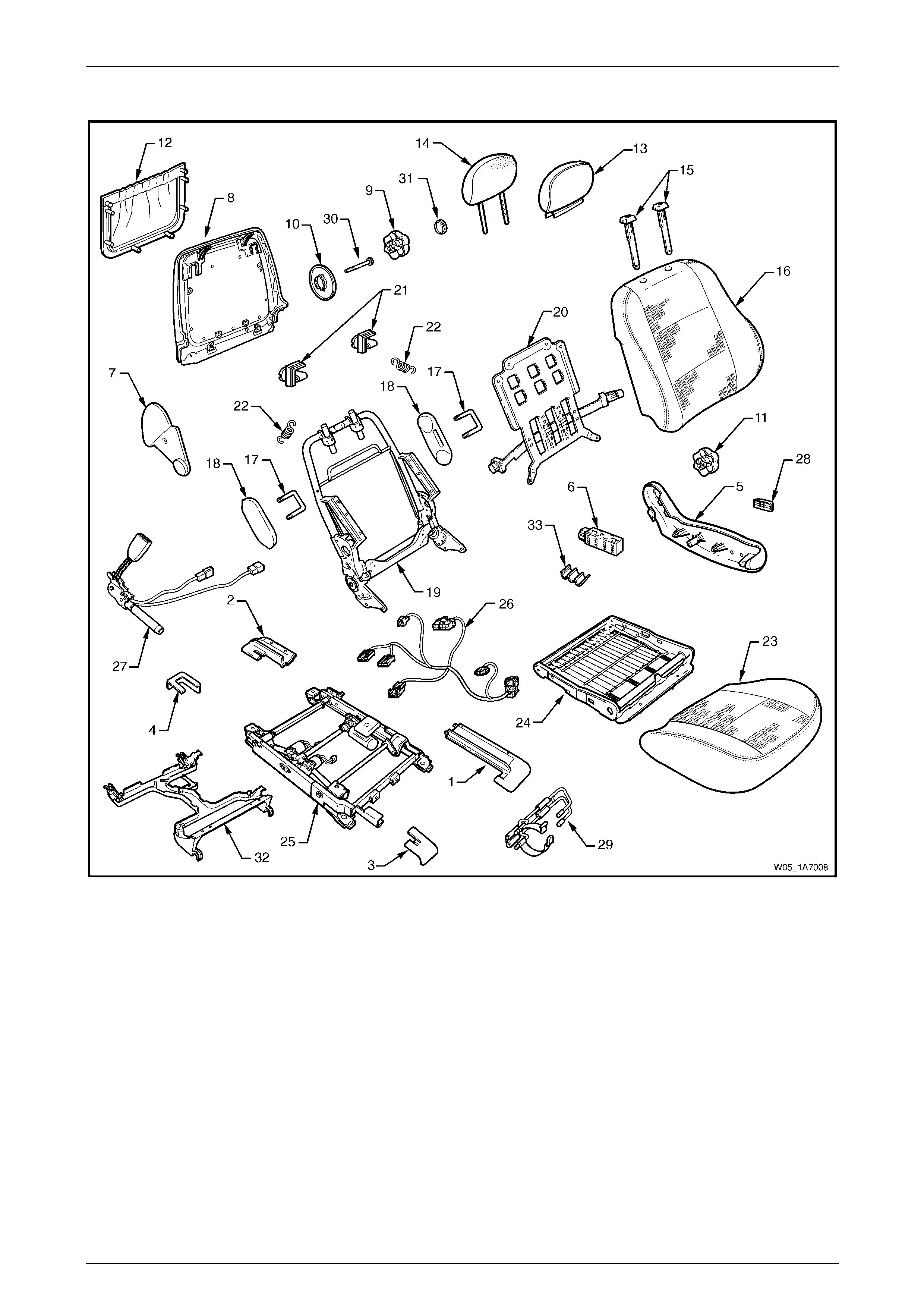
Seat Assemblies Page 1A7A–173
Page 1A7A–173
Front Seat Type 5
Figure 1A7A – 29

Seat Assemblies Page 1A7A–174
Page 1A7A–174
Legend
1 Front Seat Outer Front Cover
2 Front Seat Outer Rear Cover
3 Front Seat Inner Front Cover
4 Front Seat Inner Rear Cover
5 Front Seat Outer Side Cover
6 Front Seat Adjustment Switch – Six-way
7 Front Seat Inner Side Cover
8 Front Seat-back Rear Cover
9 Lumbar Support Knob
10 Lumber Support Deflector Ring
11 Recline Adjuster Knob
12 Front Seat-back Map Pocket
13 Front Seat Head Restraint Cover
14 Front Seat Head Restraint Pad Assembly
15 Front Seat Head Restraint Sleeves
16 Front Seat-back Cover and Pad Assembly
17 Front Seat Dummy Block U-bolt
18 Front Seat Dummy Block Insert
19 Front Seat-back Frame Assembly
20 Lumbar Support Assembly
21 Front Seat-back Cover Retaining Clip
22 Lumbar Support Retaining Spring
23 Front Seat Cushion Cover and Pad
24 Front Seat Cushion Frame Assembly
25 Track and Height Adjust Assembly
26 Wiring Harness Assembly
27 Seatbelt Buckle & Pretensioner Assembly
28 Front Seat Adjustment Switch Knob
29 Fire Extinguisher Mounting Bracket
30 Lumbar Support Knob Screw
31 Lumbar Support Knob Cover
32 Front Seat Cable Tray
33 Wiring Harness Retaining Clip
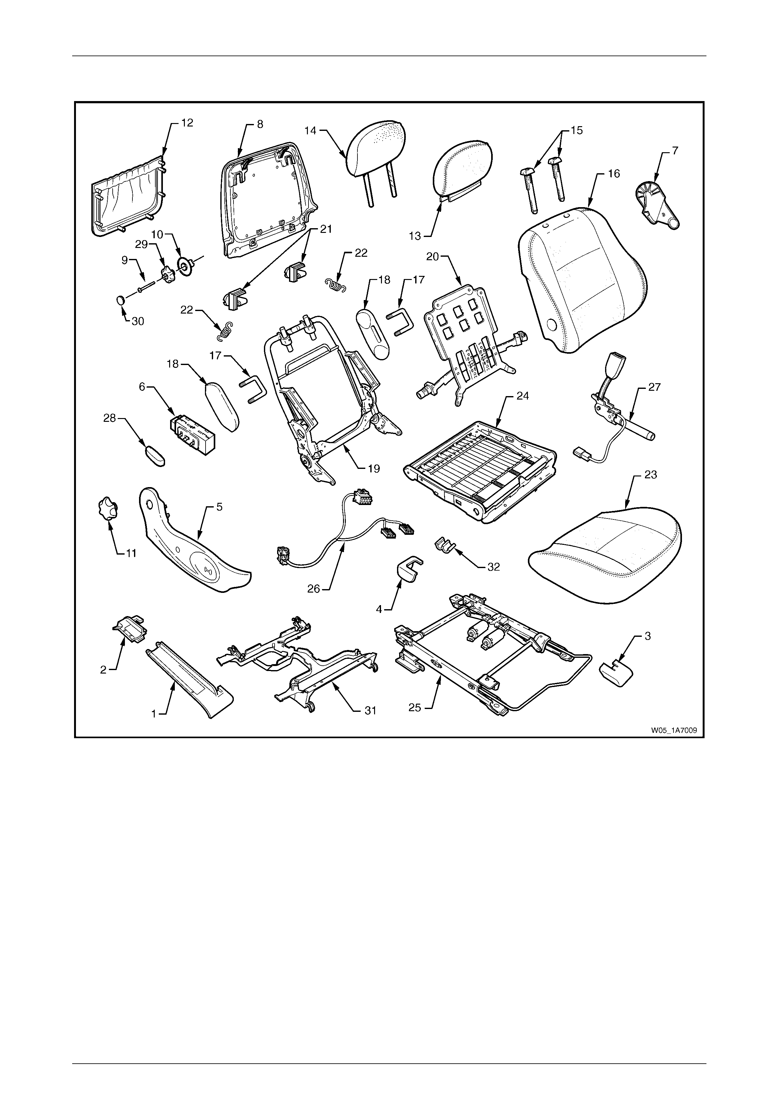
Seat Assemblies Page 1A7A–175
Page 1A7A–175
Front Seat Type 6
Figure 1A7A – 30

Seat Assemblies Page 1A7A–176
Page 1A7A–176
Legend
1 Front Seat Outer Front Cover
2 Front Seat Outer Rear Cover
3 Front Seat Inner Front Cover
4 Front Seat Inner Rear Cover
5 Front Seat Outer Side Cover
6 Front Seat Adjustment Switch – Four-way
7 Front Seat Inner Side Cover
8 Front Seat-back Rear Cover
9 Lumbar Support Knob
10 Lumber Support Deflector Ring
11 Recline Adjuster Knob
12 Front Seat-back Map Pocket
13 Front Seat Head Restraint Cover
14 Front Seat Head Restraint Pad Assembly
15 Front Seat Head Restraint Sleeves
16 Front Seat-back Cover and Pad Assembly
17 Front Seat Dummy Block U-bolt
18 Front Seat Dummy Block Insert
19 Front Seat-back Frame Assembly
20 Lumbar Support Assembly
21 Front Seat-back Cover retaining Clip
22 Lumbar Support Retaining Spring
23 Front Seat Cushion Cover and Pad
24 Front Seat Cushion Frame Assembly
25 Track and Height Adjust Assembly
26 Wiring Harness Assembly
27 Seatbelt Buckle & Pretensioner Assembly
28 Front Seat Adjustment Switch Knob
29 Lumbar Support Knob Screw
30 Lumbar Support Knob Cover
31 Front Seat Cable Tray
32 Wiring Harness Retaining Clip
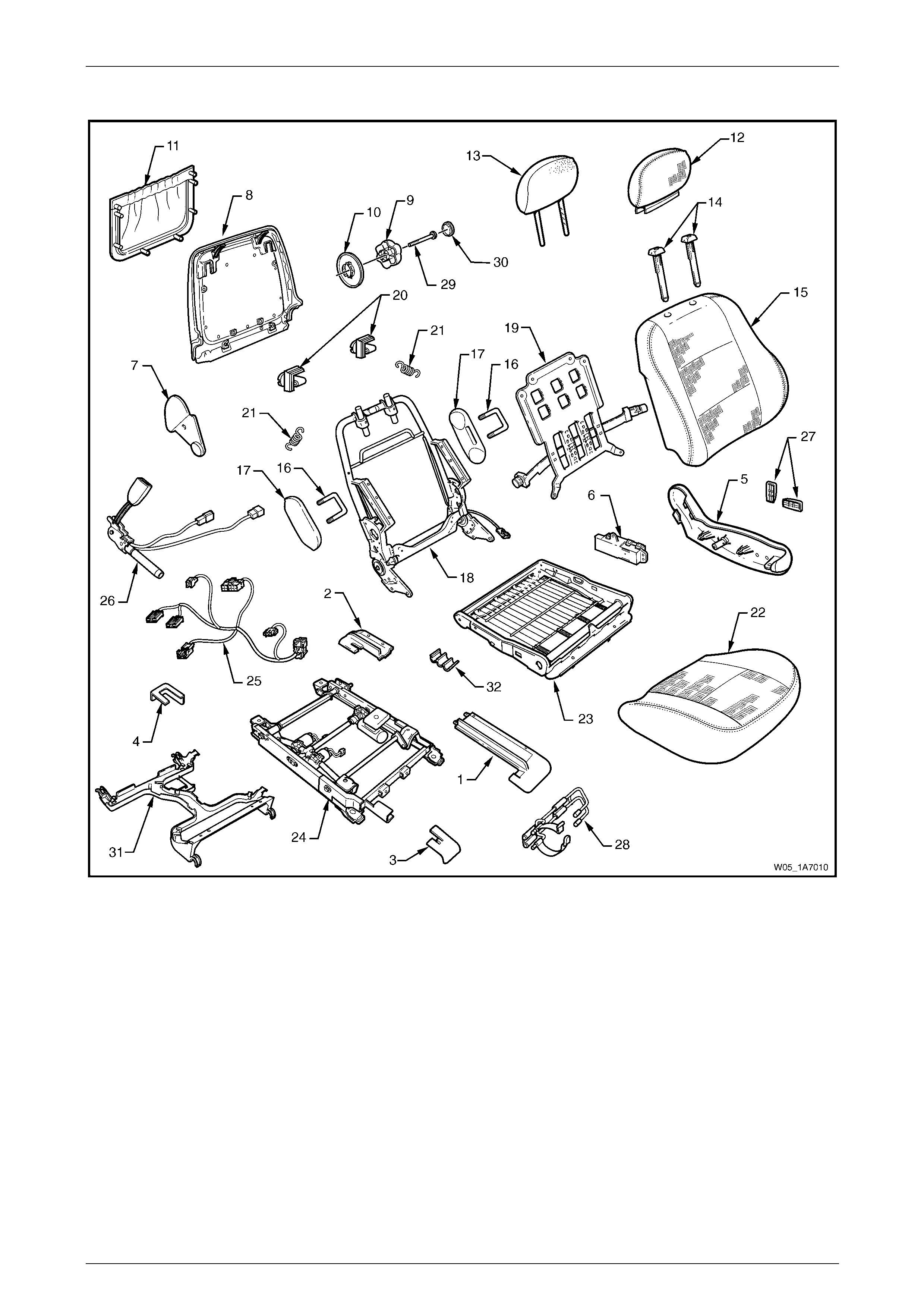
Seat Assemblies Page 1A7A–177
Page 1A7A–177
Front Seat Type 7
Figure 1A7A – 31

Seat Assemblies Page 1A7A–178
Page 1A7A–178
Legend
1 Front Seat Outer Front Cover
2 Front Seat Outer Rear Cover
3 Front Seat Inner Front Cover
4 Front Seat Inner Rear Cover
5 Front Seat Outer Side Cover
6 Front Seat Adjustment Switch – Eight-way
7 Front Seat Inner Side Cover
8 Front Seat-back Rear Cover
9 Lumbar Support Knob
10 Lumber Support Deflector Ring
11 Front Seat-back Map Pocket
12 Front Seat Head Restraint Cover
13 Front Seat Head Restraint Pad Assembly
14 Front Seat Head Restraint Sleeves
15 Front Seat-back Cover and Pad Assembly
16 Front Seat Dummy Block U-bolt
17 Front Seat Dummy Block Insert
18 Front Seat-back Frame Assembly
19 Lumbar Support Assembly
20 Front Seat-back Cover retaining Clip
21 Lumbar Support Retaining Spring
22 Front Seat Cushion Cover and Pad
23 Front Seat Cushion Frame Assembly
24 Track and Height Adjust Assembly
25 Wiring Harness Assembly
26 Seatbelt Buckle & Pretensioner Assembly
27 Front Seat Adjustment Switch Knobs
28 Fire Extinguisher Mounting Bracket
29 Lumbar Support Knob Screw
30 Lumbar Support Knob Cover
31 Front Seat Cable Tray
32 Wiring Harness Retaining Clip
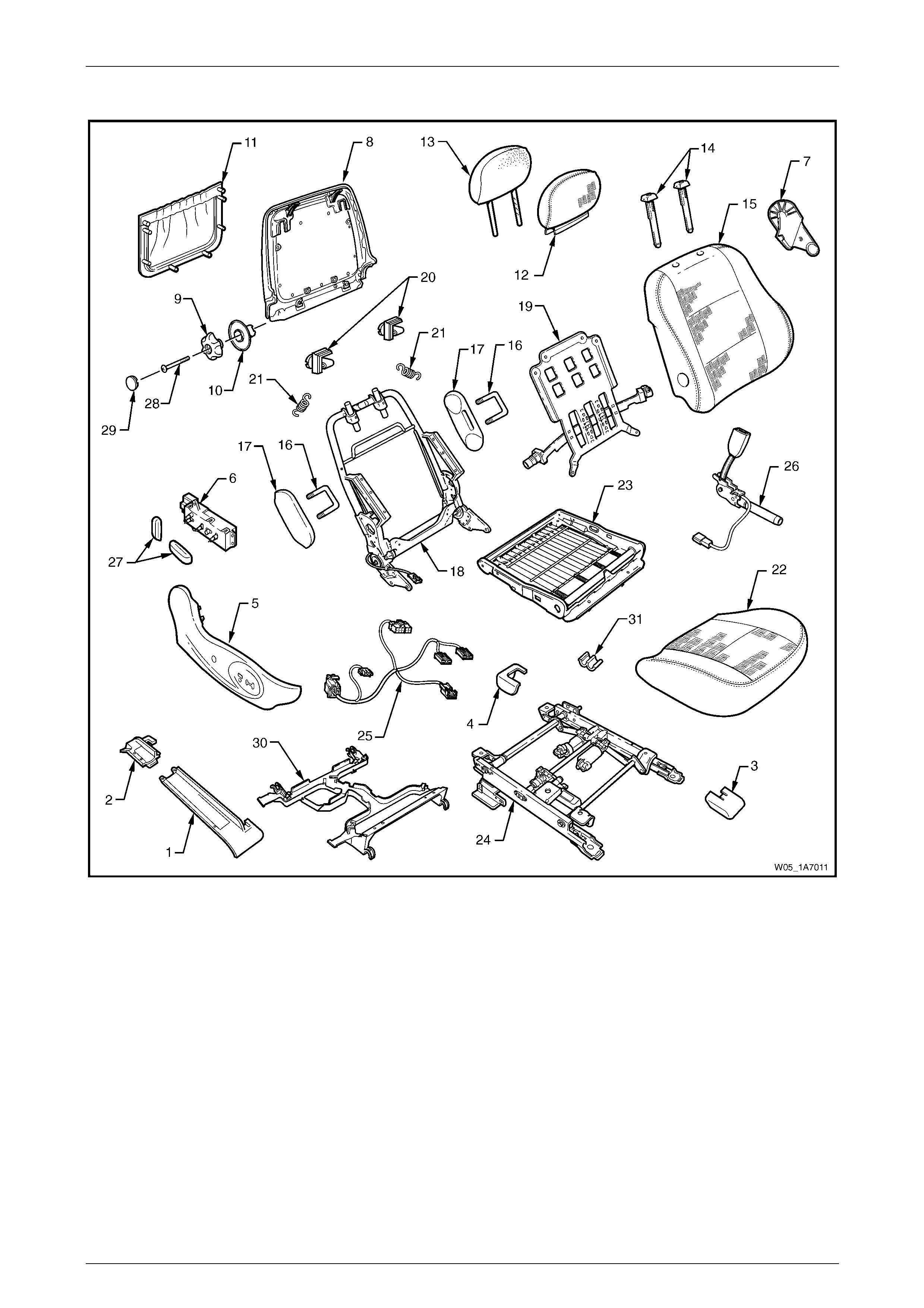
Seat Assemblies Page 1A7A–179
Page 1A7A–179
Front Seat Type 8
Figure 1A7A – 32

Seat Assemblies Page 1A7A–180
Page 1A7A–180
Legend
1 Front Seat Outer Front Cover
2 Front Seat Outer Rear Cover
3 Front Seat Inner Front Cover
4 Front Seat Inner Rear Cover
5 Front Seat Outer Side Cover
6 Front Seat Adjustment Switch – Eight-way
7 Front Seat Inner Side Cover
8 Front Seat-back Rear Cover
9 Lumbar Support Knob
10 Lumber Support Deflector Ring
11 Front Seat-back Map Pocket
12 Front Seat Head Restraint Cover
13 Front Seat Head Restraint Pad Assembly
14 Front Seat Head Restraint Sleeves
15 Front Seat-back Cover and Pad Assembly
16 Front Seat Dummy Block U-bolt
17 Front Seat Dummy Block Insert
18 Front Seat-back Frame Assembly
19 Lumbar Support Assembly
20 Front Seat-back Cover retaining Clip
21 Lumbar Support Retaining Spring
22 Front Seat Cushion Cover and Pad
23 Front Seat Cushion Frame Assembly
24 Track and Height Adjust Assembly
25 Wiring Harness Assembly
26 Seatbelt Buckle & Pretensioner Assembly
27 Front Seat Adjustment Switch Knobs
28 Lumbar Support Knob Screw
29 Lumbar Support Knob Cover
30 Front Seat Cable Tray
31 Wiring Harness Retaining Clip
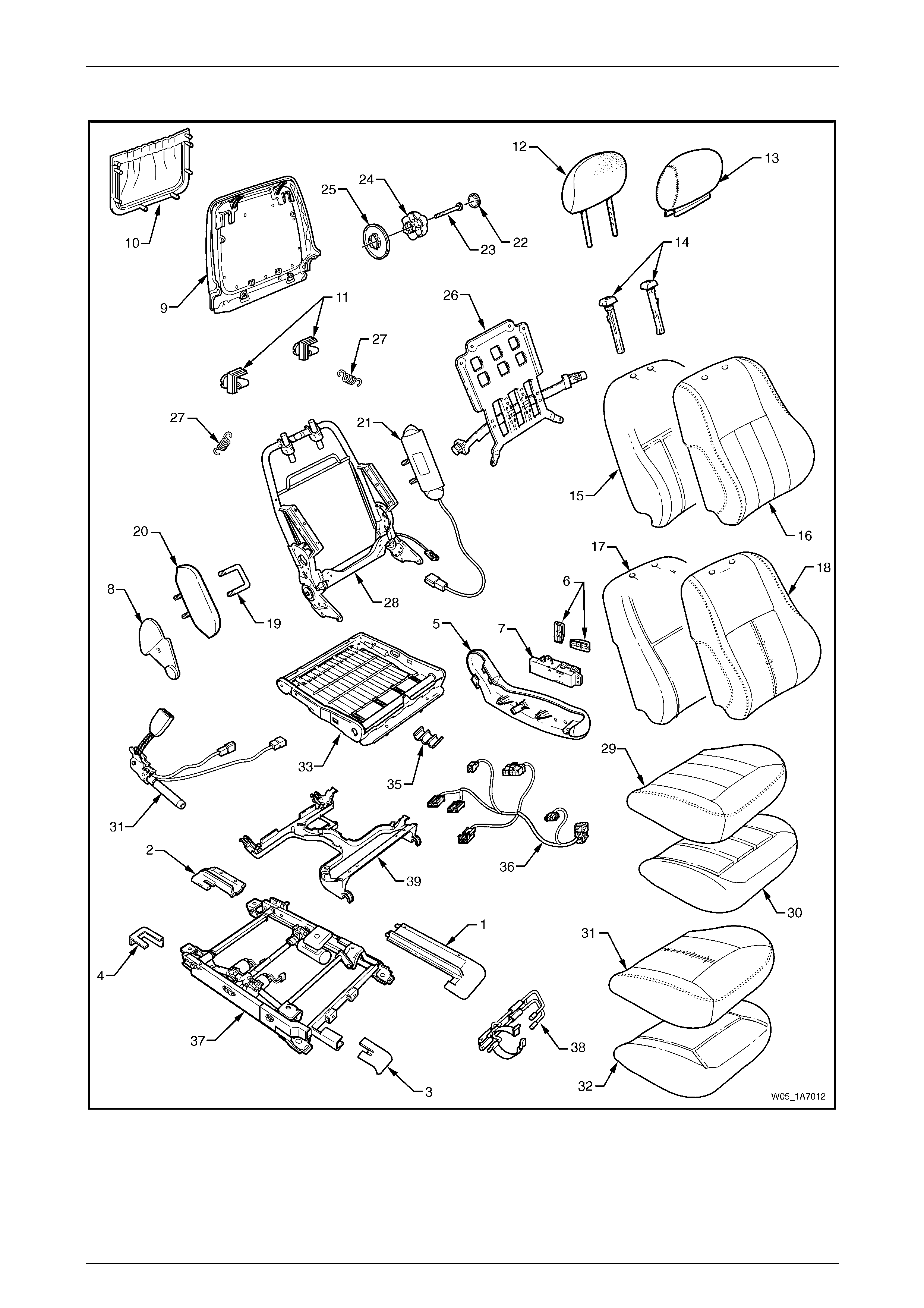
Seat Assemblies Page 1A7A–181
Page 1A7A–181
Front Seat Type 9
Figure 1A7A – 33

Seat Assemblies Page 1A7A–182
Page 1A7A–182
Legend
1 Front Seat Outer Front Cover
2 Front Seat Outer Rear Cover
3 Front Seat Inner Front Cover
4 Front Seat Inner Rear Cover
5 Front Seat Outer Side Cover
6 Front Seat Adjustment Switch Knobs
7 Front Seat Adjustment Switch – Eight-way
8 Front Seat Inner Side Cover
9 Front Seat-back Rear Cover
10 Front Seat-back Map Pocket
11 Front Seat-back Cover Retaining Clips
12 Front Seat Head Restraint Pad Assembly
13 Front Seat Head Restraint Cover
14 Front Seat Head Restraint Sleeves
15 Front Seat-back Pad – Cloth Cover
16 Front Seat-back Cloth Cover
17 Front Seat-back Pad – Leather Cover
18 Front Seat-back Leather Cover
19 Front Seat Dummy Block U-bolt
20 Front Seat Dummy Block Insert
21 Side Impact Airbag Assembly
22 Lumbar Support Knob Cover
23 Lumbar Support Knob Screw
24 Lumbar Support Knob
25 Lumbar Support Deflector Ring
26 Lumbar Support Assembly
27 Lumbar Support Retaining Spring
28 Front Seat-back Frame Assembly
29 Front Seat Cushion Cloth Cover
30 Front Seat Cushion Pad – Cloth Cover
31 Front Seat Cushion Leather Cover
32 Front Seat Cushion Pad – Leather Cover
33 Front Seat Cushion Frame Assembly
34 Seatbelt Buckle & Pretensioner Assembly
35 Wiring Harness Retaining Clip
36 Wiring Harness Assembly
37 Track and Height Adjust Assembly
38 Fire Extinguisher Mounting Bracket
39 Front Seat Cable Tray
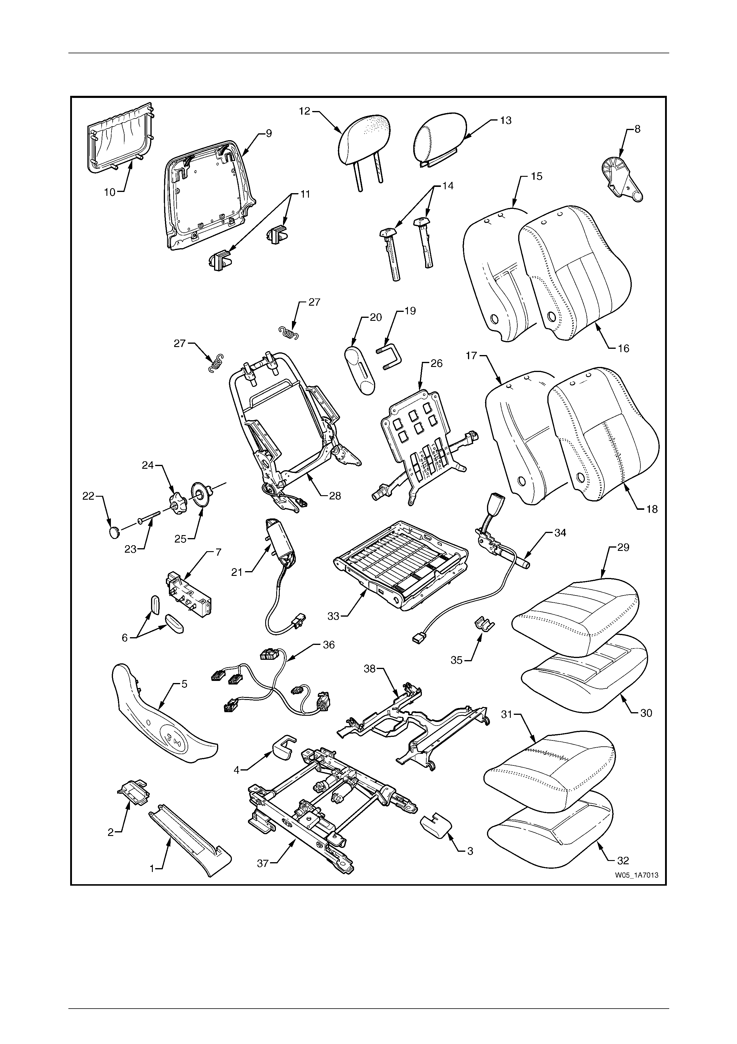
Seat Assemblies Page 1A7A–183
Page 1A7A–183
Front Seat Type 10
Figure 1A7A – 34

Seat Assemblies Page 1A7A–184
Page 1A7A–184
Legend
1 Front Seat Outer Front Cover
2 Front Seat Outer Rear Cover
3 Front Seat Inner Front Cover
4 Front Seat Inner Rear Cover
5 Front Seat Outer Side Cover
6 Front Seat Adjustment Switch Knobs
7 Front Seat Adjustment Switch – Eight-way
8 Front Seat Inner Side Cover
9 Front Seat-back Rear Cover
10 Front Seat-back Map Pocket
11 Front Seat-back Cover Retaining Clips
12 Front Seat Head Restraint Pad Assembly
13 Front Seat Head Restraint Cover
14 Front Seat Head Restraint Sleeves
15 Front Seat-back Pad – Cloth Cover
16 Front Seat-back Cloth Cover
17 Front Seat-back Pad – Leather Cover
18 Front Seat-back Leather Cover
19 Front Seat Dummy Block U-bolt
20 Front Seat Dummy Block Insert
21 Side Impact Airbag Assembly
22 Lumbar Support Knob Cover
23 Lumbar Support Knob Screw
24 Lumbar Support Knob
25 Lumbar Support Deflector Ring
26 Lumbar Support Assembly
27 Lumbar Support Retaining Spring
28 Front Seat-back Frame Assembly
29 Front Seat Cushion Cloth Cover
30 Front Seat Cushion Pad – Cloth Cover
31 Front Seat Cushion Leather Cover
32 Front Seat Cushion Pad – Leather Cover
33 Front Seat Cushion Frame Assembly
34 Seatbelt Buckle & Pretensioner Assembly
35 Wiring Harness Retaining Clip
36 Wiring Harness Assembly
37 Track and Height Adjust Assembly
38 Front Seat Cable Tray
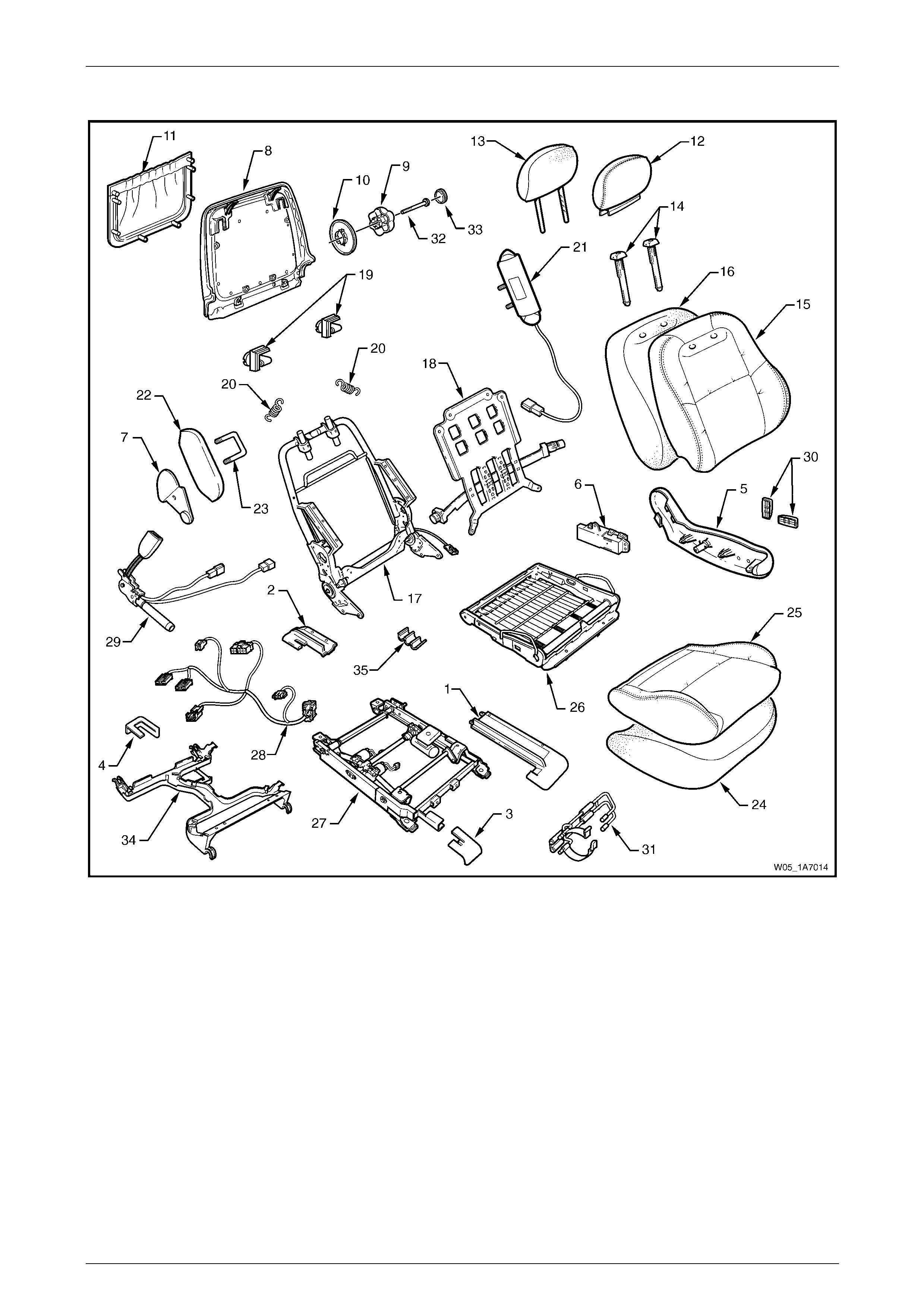
Seat Assemblies Page 1A7A–185
Page 1A7A–185
Front Seat Type 11
Figure 1A7A – 35

Seat Assemblies Page 1A7A–186
Page 1A7A–186
Legend
1 Front Seat Outer Front Cover
2 Front Seat Outer Rear Cover
3 Front Seat Inner Front Cover
4 Front Seat Inner Rear Cover
5 Front Seat Outer Side Cover
6 Front Seat Adjustment Switch – Eight-way
7 Front Seat Inner Side Cover
8 Front Seat-back Rear Cover
9 Lumbar Support Knob
10 Lumber Support Deflector Ring
11 Front Seat-back Map Pocket
12 Front Seat Head Restraint Cover
13 Front Seat Head Restraint Pad Assembly
14 Front Seat Head Restraint Sleeves
15 Front Seat-back Cover
16 Front Seat-back Pad
17 Front Seat-back Frame Assembly
18 Lumbar Support Assembly
19 Front Seat-back Cover retaining Clip
20 Lumbar Support Retaining Spring
21 Side Impact Airbag Assembly
22 Front Seat Dummy Block Insert
23 Front Seat Dummy Block U-bolt
24 Front Seat Cushion Pad
25 Front Seat Cushion Cover
26 Front Seat Cushion Frame Assembly
27 Track and Height Adjust Assembly
28 Wiring Harness Assembly
29 Seatbelt Buckle & Pretensioner Assembly
30 Front Seat Adjustment Switch Knobs
31 Fire Extinguisher Mounting Bracket
32 Lumbar Support Knob Screw
33 Lumbar Support Knob Cover
34 Front Seat Cable Tray
35 Wiring Harness Retaining Clip
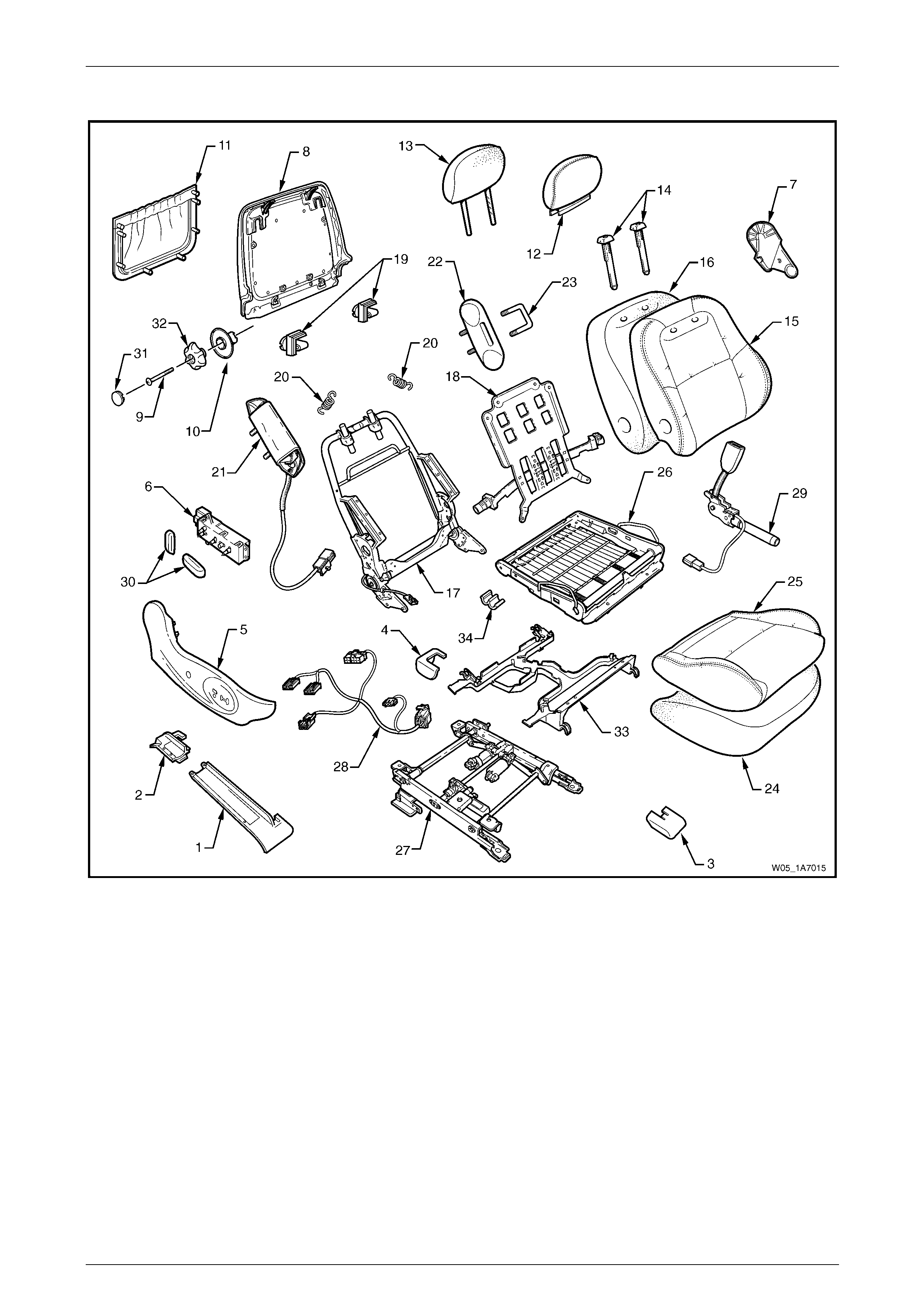
Seat Assemblies Page 1A7A–187
Page 1A7A–187
Front Seat Type 12
Figure 1A7A – 36

Seat Assemblies Page 1A7A–188
Page 1A7A–188
Legend
1 Front Seat Outer Front Cover
2 Front Seat Outer Rear Cover
3 Front Seat Inner Front Cover
4 Front Seat Inner Rear Cover
5 Front Seat Outer Side Cover
6 Front Seat Adjustment Switch – Eight-way
7 Front Seat Inner Side Cover
8 Front Seat-back Rear Cover
9 Lumbar Support Knob Screw
10 Lumber Support Deflector Ring
11 Front Seat-back Map Pocket
12 Front Seat Head Restraint Cover
13 Front Seat Head Restraint Pad Assembly
14 Front Seat Head Restraint Sleeves
15 Front Seat-back Cover
16 Front Seat-back Pad
17 Front Seat-back Frame Assembly
18 Lumbar Support Assembly
19 Front Seat-back Cover Retaining Clip
20 Lumbar Support Retaining Spring
21 Side Impact Airbag Assembly
22 Front Seat Dummy Block Insert
23 Front Seat Dummy Block U-bolt
24 Front Seat Cushion Pad
25 Front Seat Cushion Cover
26 Front Seat Cushion Frame Assembly
27 Track and Height Adjust Assembly
28 Wiring Harness Assembly
29 Seatbelt Buckle & Pretensioner Assembly
30 Front Seat Adjustment Switch Knobs
31 Lumbar Support Knob Cover
32 Lumbar Support Knob
33 Front Seat Cable Tray
34 Wiring Harness Retaining Clip
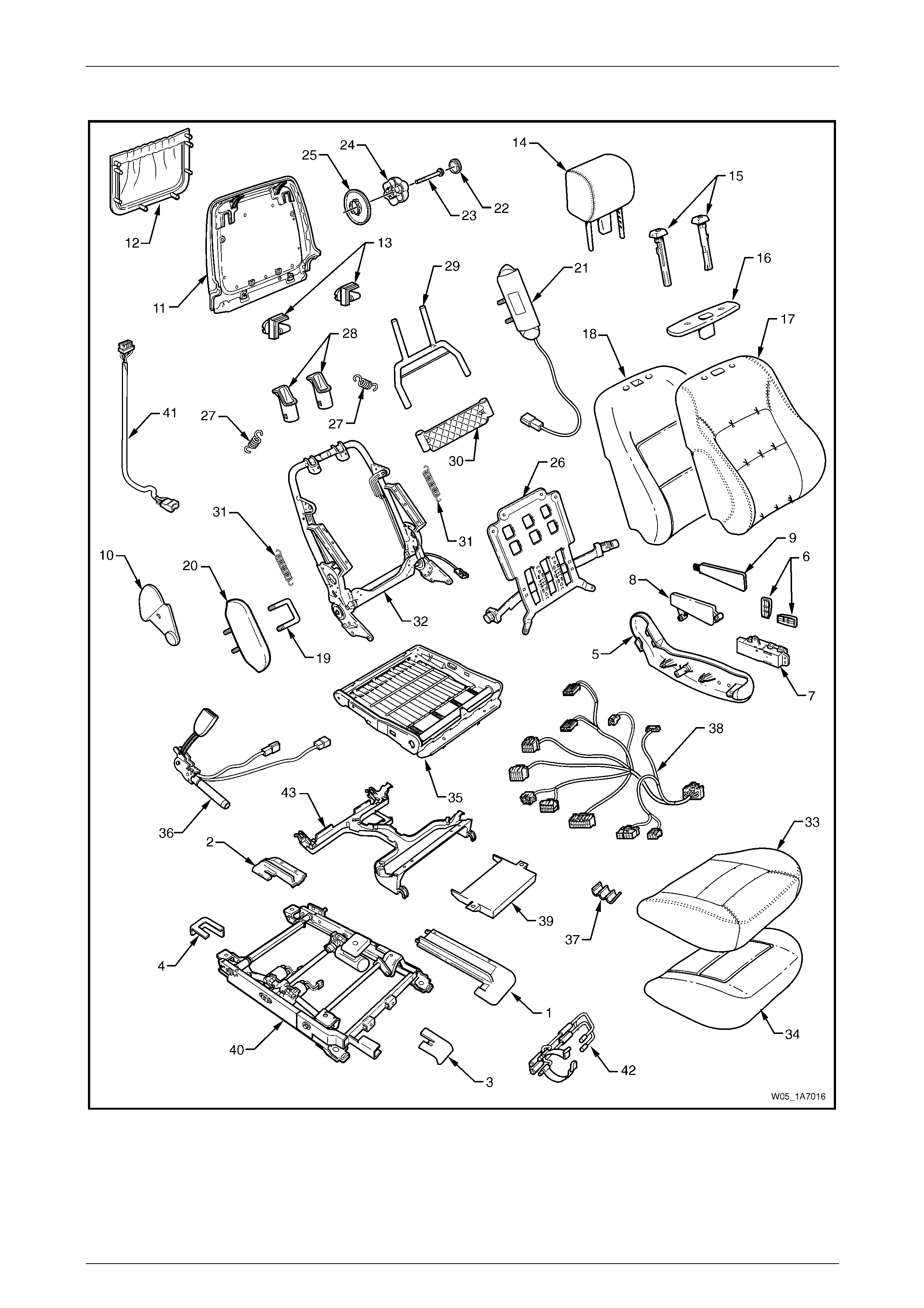
Seat Assemblies Page 1A7A–189
Page 1A7A–189
Front Seat Type 13
Figure 1A7A – 37

Seat Assemblies Page 1A7A–190
Page 1A7A–190
Legend
1 Front Seat Outer Front Cover
2 Front Seat Outer Rear Cover
3 Front Seat Inner Front Cover
4 Front Seat Inner Rear Cover
5 Front Seat Outer Side Cover
6 Front Seat Adjustment Switch Knobs
7 Front Seat Adjustment Switch – Eight-way
8 Memory Position Switch Cover
9 Memory Position Switch Assembly
10 Front Seat Inner Side Cover
11 Front Seat-back Rear Cover
12 Front Seat-back Map Pocket
13 Front Seat-back Cover Retaining Clips
14 Front Seat Head Restraint Assembly*
15 Front Seat Head Restraint Sleeves
16 Front Seat Head Restraint Guide Cover
17 Front Seat-back Cover
18 Front Seat-back Pad
19 Front Seat Dummy Block U-bolt
20 Front Seat Dummy Block Insert
21 Side Impact Airbag Assembly
22 Lumbar Support Knob Cover
23 Lumbar Support Knob Screw
24 Lumbar Support Knob
25 Lumbar Support Deflector Ring
26 Lumbar Support Assembly
27 Lumbar Support Retaining Spring
28 Active Head Restraint Frame Sleeves
29 Active Head Restraint Frame Assembly
30 Active Head Restraint Frame Support Strap
31 Active Head Restraint Frame Retaining Spring
32 Front Seat-back Frame Assembly
33 Front Seat Cushion Cover
34 Front Seat Cushion Pad
35 Front Seat Cushion Frame Assembly
36 Seatbelt Buckle & Pretensioner Assembly
37 Wiring Harness Retaining Clip
38 Wiring Harness Assembly
39 Seat Memory Module
40 Track and Height Adjust Assembly
41 Rear Seat Entertainment Lower Wiring Harness Assembly
42 Fire Extinguisher Mounting Bracket
43 Front Seat Cable Tray
* Refer to Figure 1A7A – 39 for the front head restraint assembly compone nts.
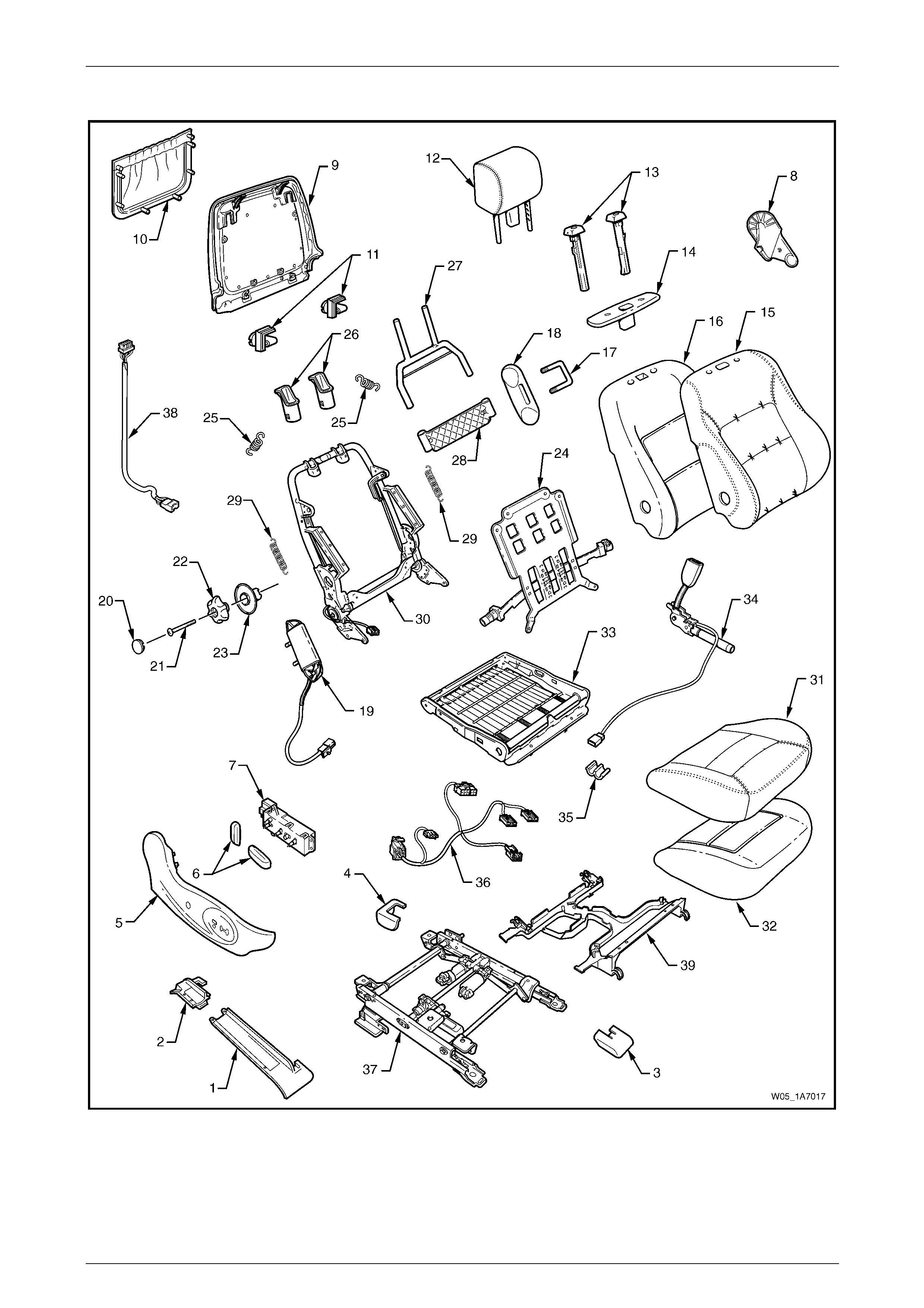
Seat Assemblies Page 1A7A–191
Page 1A7A–191
Front Seat Type 14
Figure 1A7A – 38

Seat Assemblies Page 1A7A–192
Page 1A7A–192
Legend
1 Front Seat Outer Front Cover
2 Front Seat Outer Rear Cover
3 Front Seat Inner Front Cover
4 Front Seat Inner Rear Cover
5 Front Seat Outer Side Cover
6 Front Seat Adjustment Switch Knobs
7 Front Seat Adjustment Switch – Eight-way
8 Front Seat Inner Side Cover
9 Front Seat-back Rear Cover
10 Front Seat-back Map Pocket
11 Front Seat-back Cover Retaining Clips
12 Front Seat Head Restraint Assembly*
13 Front Seat Head Restraint Sleeves
14 Front Seat Head Restraint Guide Cover
15 Front Seat-back Cover
16 Front Seat-back Pad Cover
17 Front Seat Dummy Block U-bolt
18 Front Seat Dummy Block Insert
19 Side Impact Airbag Assembly
20 Lumbar Support Knob Cover
21 Lumbar Support Knob Screw
22 Lumbar Support Knob
23 Lumbar Support Deflector Ring
24 Lumbar Support Assembly
25 Lumbar Support Retaining Spring
26 Active Head Restraint Frame Sleeves
27 Active Head Restraint Frame Assembly
28 Active Head Restraint Frame Support Strap
29 Active Head Restraint Frame Retaining Spring
30 Front Seat-back Frame Assembly
31 Front Seat Cushion Cover
32 Front Seat Cushion Pad
33 Front Seat Cushion Frame Assembly
34 Seatbelt Buckle & Pretensioner Assembly
35 Wiring Harness Retaining Clip
36 Wiring Harness Assembly
37 Track and Height Adjust Assembly
38 Rear Seat Entertainment Lower Wiring Harness Assembly
39 Front Seat Cable Tray
* Refer to Figure 1A7A – 39 for the front head restraint assembly compone nts.

Seat Assemblies Page 1A7A–193
Page 1A7A–193
Front Seat Type 3, 4, 13 & 14 Head Restraint Assembly
Figure 1A7A – 39
Legend
1 Rear Seat Entertainment Head Rest Escutcheon Assembly
2 Rear Seat Entertainment Circuit Board
3 Rear Seat Entertainment Screen Bezel
4 Rear Seat Entertainment Screen Assembly
5 Rear Seat Entertainment Screen Pivot Hinge
6 Rear Seat Entertainment Screen Mounting Plate
7 Rear Seat Entertainment Ribbon Harness
8 Rear Seat Entertainment Upper Harness
9 Front Seat Head Restraint Cover
10 Front Seat Head Restraint Pad
11 Front Seat Head Restraint Frame
12 Front Seat Head Restraint Wiring Cover
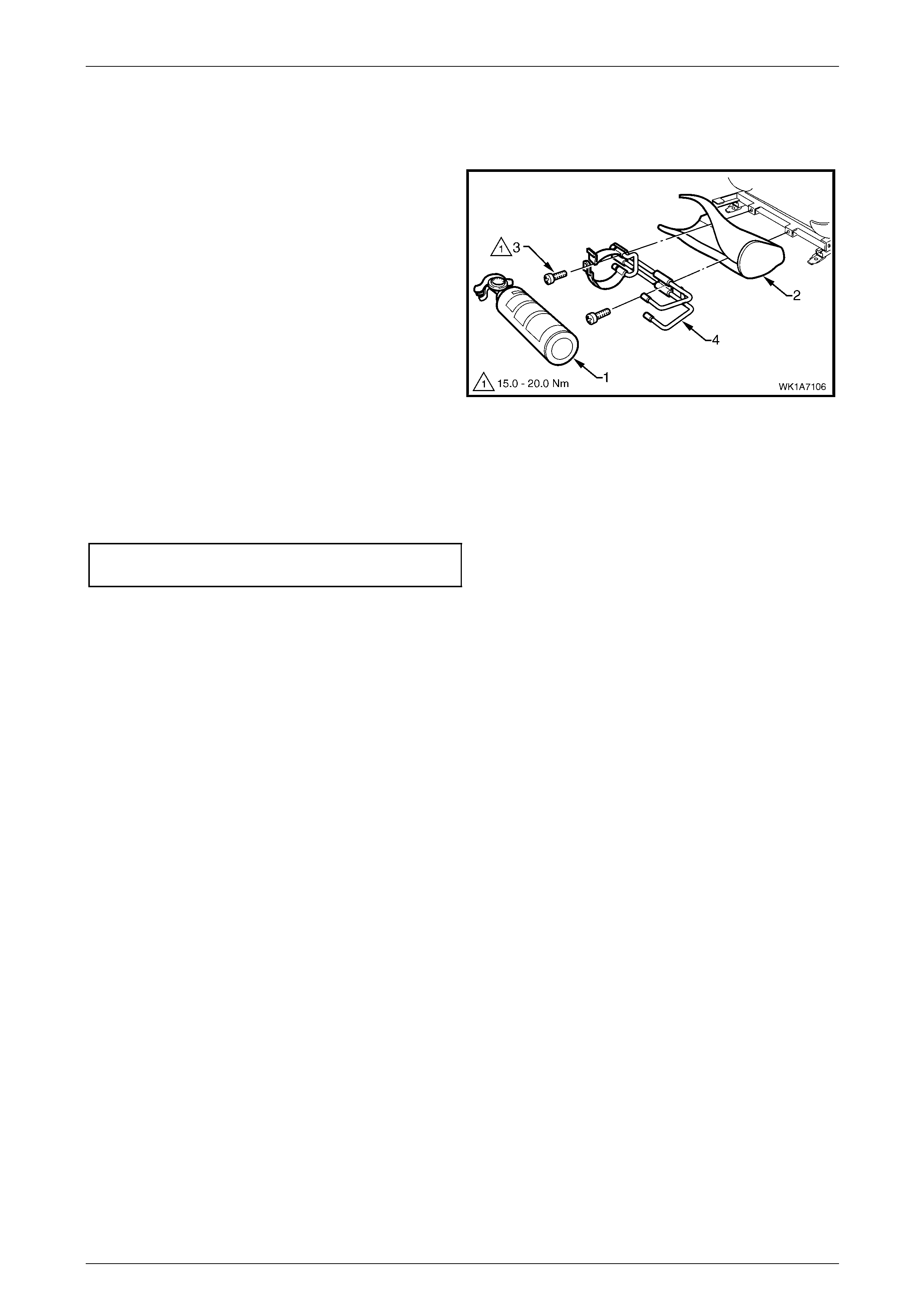
Seat Assemblies Page 1A7A–194
Page 1A7A–194
5.2 Fire Extinguisher Assembly
Remove
1 Remove the fire extinguisher (1) from the cover (2).
2 Remove the two screws (3) attaching the fire
extinguisher mounting br acket (4) to the track and
height adjust assembly.
3 Remove the bracket and cover from the track and
height adjust assembly. If required remove t he bracket
from the cover.
Figure 1A7A – 40
Reinstall
Reinstallation of the fire extinguisher assembly is the reverse of the removal procedure, noting the following:
Tighten the attaching screws to the correct torque specification.
Fire extinguisher mounting bracket
attaching screw torque specification.......15.0 – 20.0 Nm
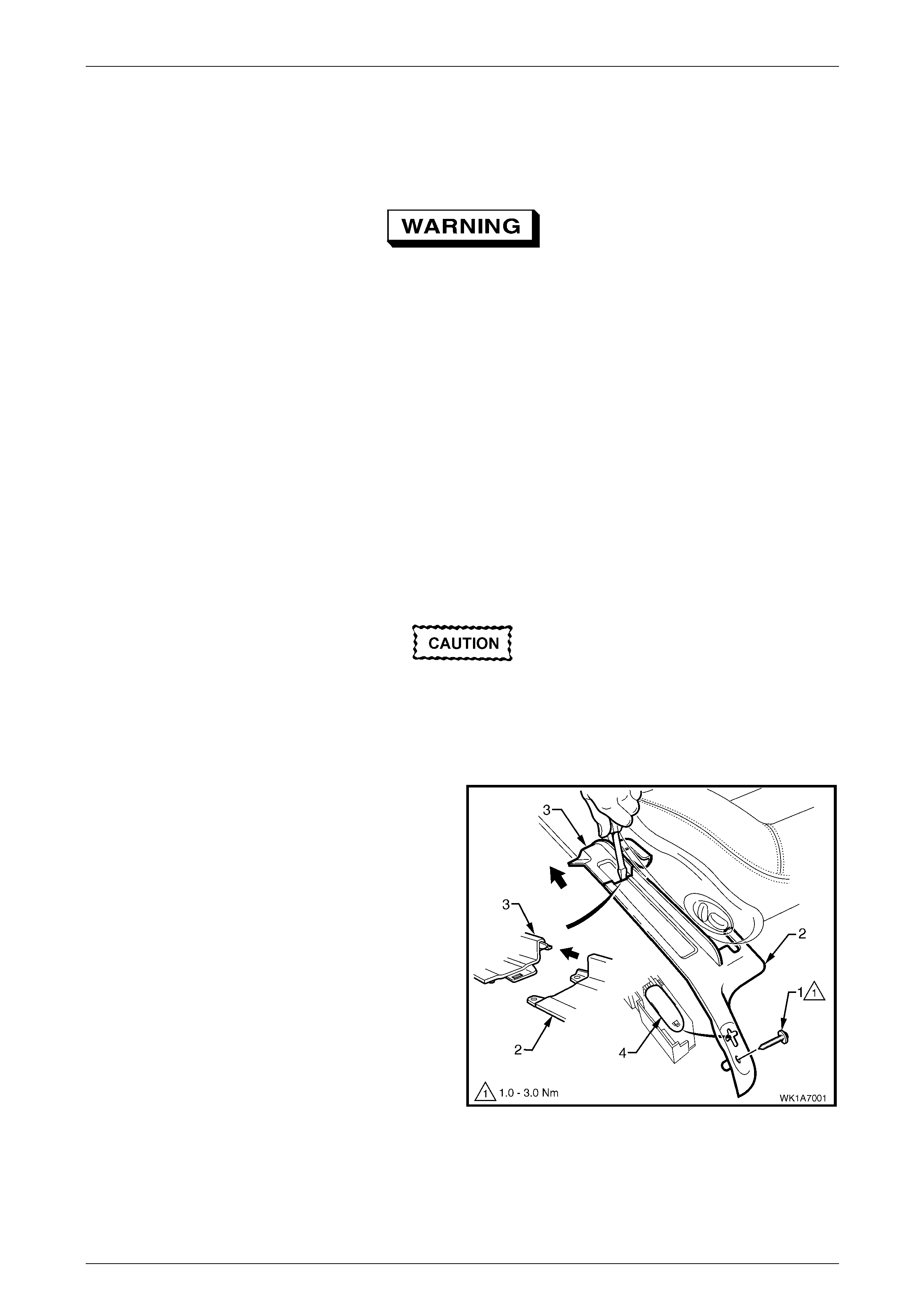
Seat Assemblies Page 1A7A–195
Page 1A7A–195
5.3 Front Seat Assembly
LT Section No. – 14-295
Before performing any service operation on a
front seat assembly fitted with side impact
airbags, ensure the occupant protection
system is disabled, refer to Section 12M
Occupant Protection System.
NOTE
If the seat assembly is to be disassembled, adjust
the seat assembly to its highest position before
disconnecting the power to the seat.
NOTE
Clean hands are essential when working on the
interior trim.
Remove
Disconnection of the battery affects certain
vehicle electronic systems. Refer to Section
00, 5 Battery Disconnection Procedures
before disconnecting the battery.
1 Disconnect the battery.
2 For the driver’s seat on right-hand drive vehicles,
remove the screw (1) attaching the front seat outer
front cover (2).
3 Using a small screwdriver, push in the centre of the
join to separate the front cover and the front seat outer
lower rear cover (3).
4 Unclip the covers from the seat track and disengag e
from the side sill trim.
5 Pull the covers apart and remove the rear c over.
6 For the driver’s seat on right-hand dr ive vehicles, slide
the front cover over the fuel filler door release lever (4)
and remove.
Figure 1A7A – 41
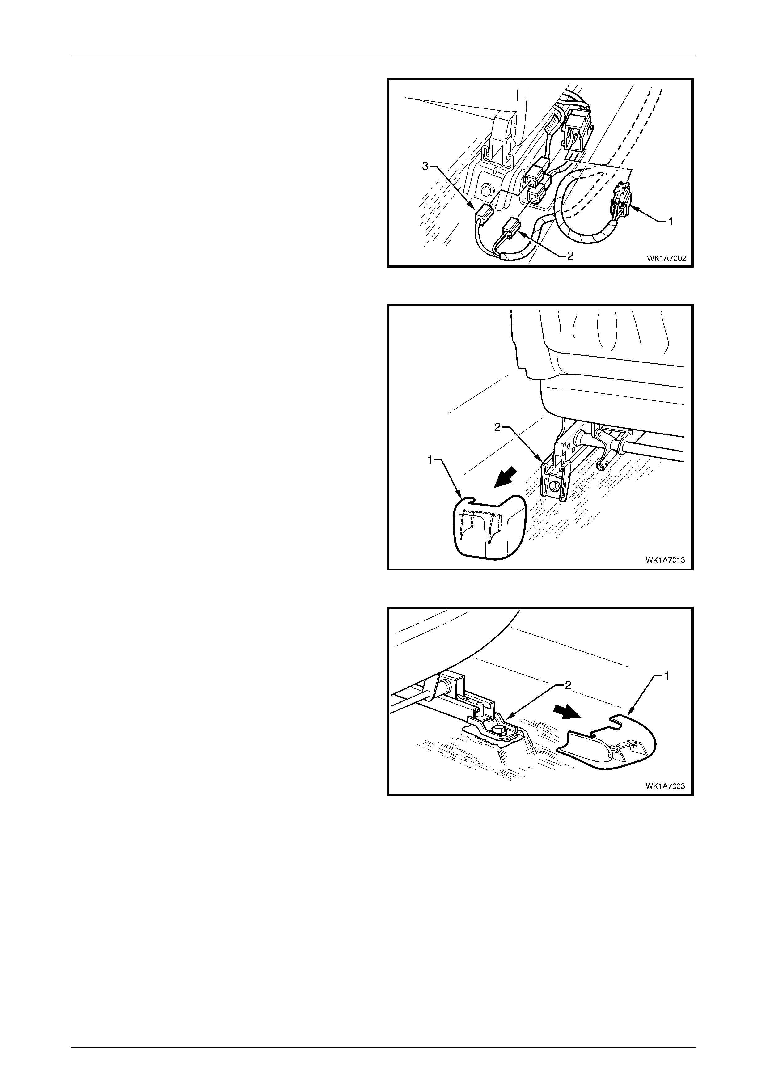
Seat Assemblies Page 1A7A–196
Page 1A7A–196
7 Disconnect the body wiring ha r ness connector (1), the
seatbelt pretensioner wiring connector (2) and the side
impact airbag wiring connector (3), if fitted.
8 On vehicles fitted with Type 3, 4, 13 & 14 front seats,
disconnect the rear seat entertainm ent lower wiring
harness from the front of the seat track.
Figure 1A7A – 42
9 Unclip the front seat inner rear cover (1) from the seat
track (2).
Figure 1A7A – 43
10 Unclip the front seat inner front cover (1) from the seat
track (2).
Figure 1A7A – 44
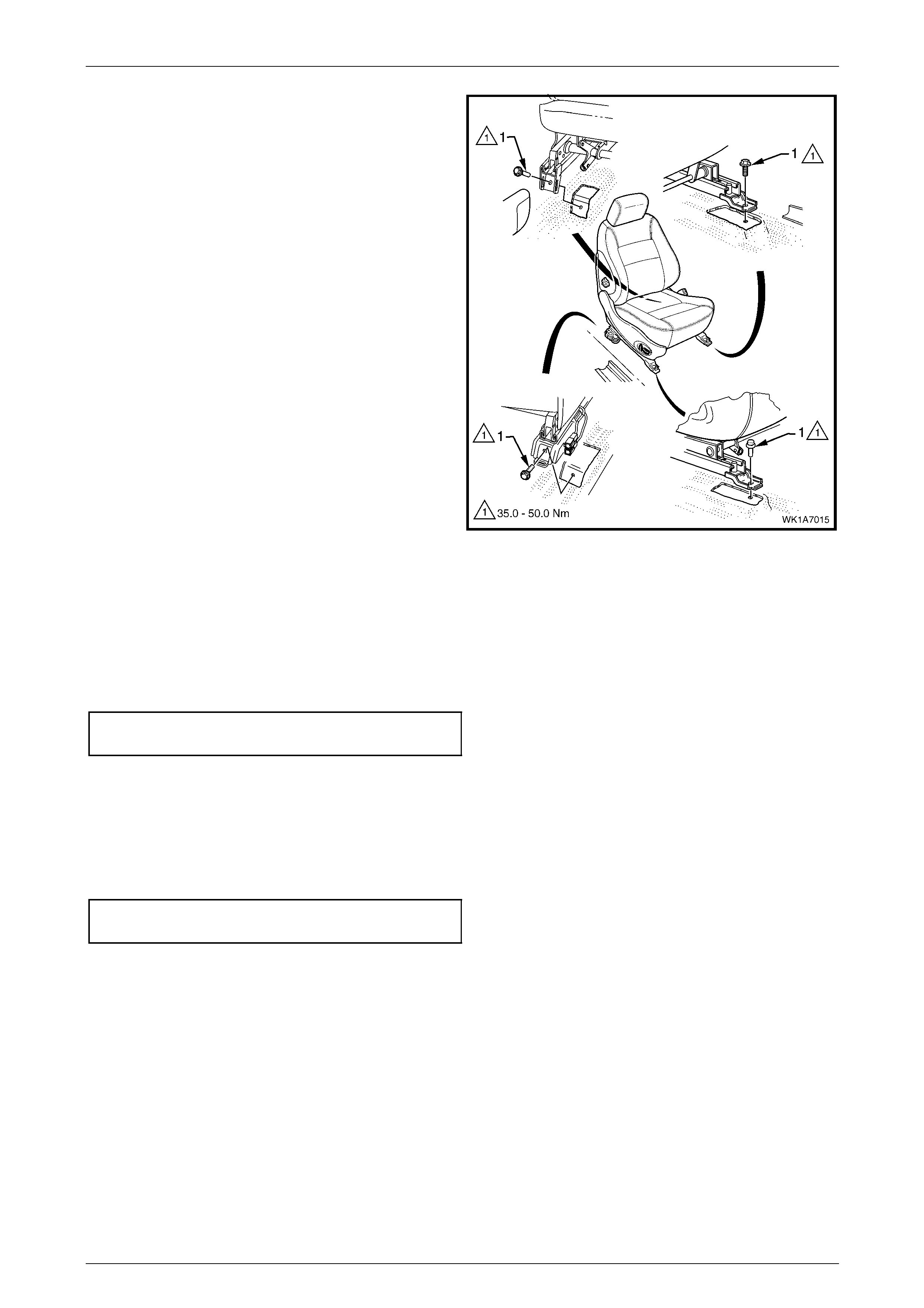
Seat Assemblies Page 1A7A–197
Page 1A7A–197
11 Remove the four screws (1) attaching the front seat to
the vehicle.
12 Remove the seat from the vehicle.
Figure 1A7A – 45
Reinstall
Reinstallation of the front seat assembly is the reverse of the removal procedure, noting the following:
1 Position the front seat assembly into the vehicle.
2 Install the four screws securing the front seat.
3 Tighten the attaching screws to the correct torque specification.
Front seat assembly attaching
screw torque specification.......................35.0 – 50.0 Nm
4 Connect the seat wiring harness connector, seatbelt pretensioner harness connector and the side impact airbag
connector.
5 Align the front seat outer cover’s retaining clips and push firmly to engage.
6 Push the front of the front seat outer cover do wn to engage the cover with the front of the seat rail.
7 For the driver’s side on right-hand drive vehicles, install the front seat outer cover attaching screw and tighten to the
specified torque.
Front seat outer front cover attaching
screw torque specification...........................1.0 – 3.0 Nm
8 Check the operation of the front seat functions. While checking the seat adjustment/operation, al so check that the
seat wiring harnesses do not foul with any of the seat’s moveable components (i.e. seat motor drive shafts, etc.).
NOTE
Type 3 and 13 front seats will require seat
memory calibration to reinstate seat memory
functions, refer to Seat Memory Calibration, Front
Seat Type 3 and 13.
9 Switch on the ignition and observe the airbag warning indic ator in the instrument cluster.
• If no fault is detected, the airbag warning indicator illuminates for approximately five seconds while the
system performs a self-test, and then extinguish.
• If a fault is present, the airbag warning indic ator will remain illuminated and a warning chime ma y soun d after
approximately three seconds. The warning message ‘SRS Airbag F ault’ is displayed in the instrument cluster
multi-function display. To diagnose the fault, refer to Section 12M Occupant Protection.

Seat Assemblies Page 1A7A–198
Page 1A7A–198
Seat Memory Calibration, Front Seat Type 3 and 13
Whenever power is interrupted to the seat memory module, the following procedure must be performed to reinstate seat
memory functions.
Step Operation Result
1 1 Operate the seat adjustment switch to move the
seat forward.
2 Operate the seat adjustment switch for 1 second to
move the seat aft.
3 Operate the seat adjustment switch to move the
seat forward.
Seat will cease movement when track limit is
reached.
Seat will move aft.
Seat will cease movement when track limit is
reached.
2 1 Operate the seat adjustment switch to move the
seat aft.
2 Operate the seat adjustment switch for 1 second to
move the seat forward.
3 Operate the seat adjustment switch to move the
seat aft.
Seat will cease movement when track limit is
reached.
Seat will move for ward.
Seat will cease movement when track limit is
reached.
3 1 Operate the seat adjustment switch to raise the
front of the seat.
2 Operate the adjustment switch for 1 second to
lower the front of the seat.
3 Operate the seat adjustment switch to raise the
front of the seat.
Seat will cease movement when upper limit is
reached.
Se at wi ll lo wer .
Seat will cease movement when upper limit is
reached.
4 1 Operate the seat adjustment switch to lower the
front of the seat.
2 Operate seat adjustment switch for 1 second to
raise the front of the seat.
3 Operate the seat adjustment switch to lower the
front of the seat.
Seat will cease movement when lower limit is
reached.
Seat will raise.
Seat will cease movement when lower limit is
reached.
5 1 Operate the seat adjustment switch to raise the rear
of the seat.
2 Operate the seat adjustment switch for 1 second to
lower the rear of the seat.
3 Operate the seat adjustment switch to raise the rear
of the seat.
Seat will cease movement when upper limit is
reached.
Se at wi ll lo wer .
Seat will cease movement when upper limit is
reached.
6 1 Operate the seat adjustment switch to lower the
rear of the seat.
2 Operate the seat adjustment switch for 1 second to
raise the rear of the seat.
3 Operate the seat adjustment switch to lower the
rear of the seat.
Seat will cease movement when lower limit is
reached.
Seat will raise.
Seat will cease movement when lower limit is
reached.
7 1 Operate the seat adjustment switch to move the
seat-back aft.
2 Operate the seat adjustment switch for 1 second to
move the seat-back forward.
3 Operate the seat adjustment switch to move the
seat-back aft.
Hold switch until lower limit is reached. This
does not have to be mechanical limit.
Seat-back will move forward.
Hold switch until lower limit is reached. This
should be same position as in 1.
8 1 Operate the seat adjustment switch to move the
seat-back forward.
2 Operate the seat adjustment switch for 1 second to
move the seat-back aft.
3 Operate the seat adjustment switch to move the
seat-back forward.
Hold switch until upper lim it is reached. This
does not have to be mechanical limit.
Seat-back will move aft.
Hold switch until upper lim it is reached. This
should be same position as in 1.
9 Press the mirror dip/memory store (M) button for 1
second. Stores the calibration into memory. A three-
tone chime sounds to confirm storage.

Seat Assemblies Page 1A7A–199
Page 1A7A–199
To test if the seat limits have been correctly calibrated, p erform the following:
Step Operation Result
1 Operate the seat adjustment switch in one direction
(fore/aft, raise/lower, etc.). Hold until seat stops.
2 Release the switch briefly. –
3 Operate the switch in the same direction and hold for 3
seconds. The motor will not operate for 2 seconds, then
operates for 0.5 second.
This is a limp-home function that allo ws the
seat to be manually adjusted should a sensor
fail.
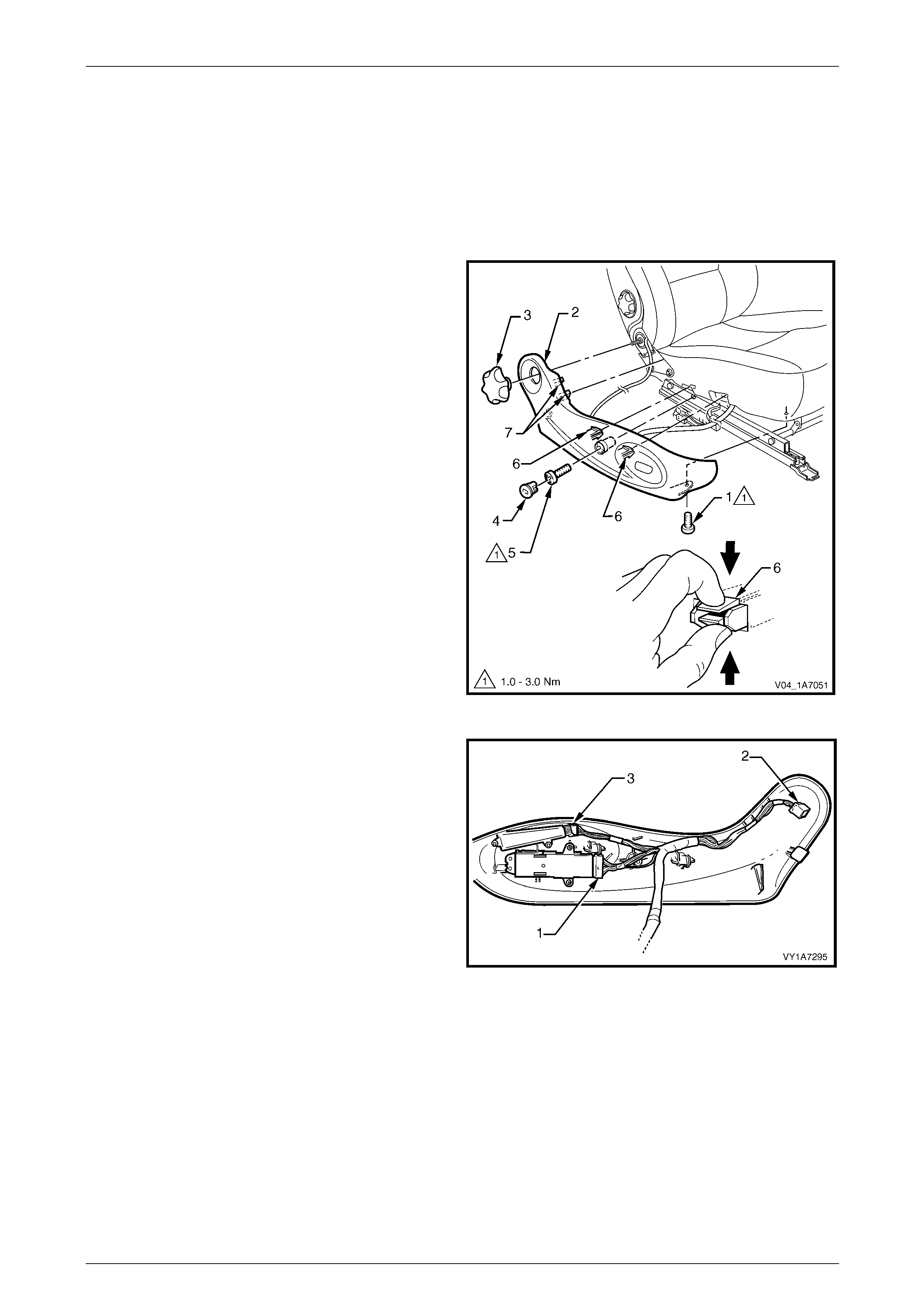
Seat Assemblies Page 1A7A–200
Page 1A7A–200
5.4 Front Seat Outer Side Cover Assembl y
LT Section No. – 14-322
Remove
1 Raise the seat to the full-up position.
2 Remove the screw (1) from the front of the front seat
outer side cover (2).
3 If required, carefully prise the recliner knob (3) from
the seat assembly.
4 Remove the plug (4) by rotating the plug a nti-
clockwise, one quarter of a turn.
5 Remove the screw (5) located behind the plu g.
6 Reach up under the seat assembly and squeeze
together the two retaining tangs (6), on the i nner side
of the side cover while gently pulling the cover.
7 Gently pull the side cover away from the seat to
disengage the two clips (7) attached to the seat-back
frame assembly.
NOTE
Only remove the side cover far enough away
from the seat cushion assembly to gain access
to the seat wiring harness connectors.
Figure 1A7A – 46
8 Where fitted, disconnect the front seat adjustment
switch connector (1), recline motor harness connector
(2) and the memory position switch connector (3) and
unclip the harness from the side cover.
9 Remove the side cover assembly.
Figure 1A7A – 47
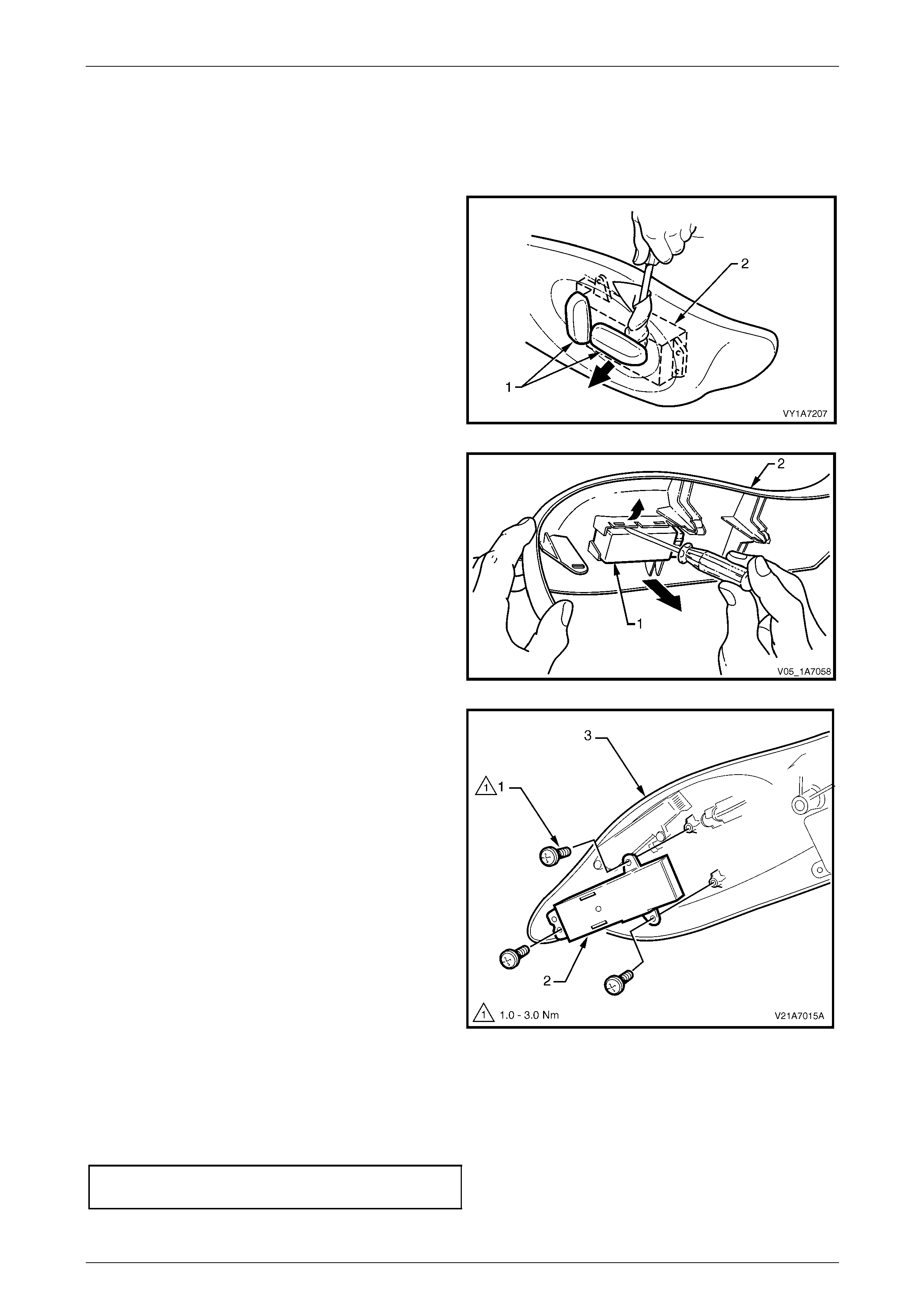
Seat Assemblies Page 1A7A–201
Page 1A7A–201
Disassemble
Front Seat Adjustment Switch
Remove
1 Depending on moveme nt functions, remove the one or
two adjustment knobs (1) from the front seat
adjustment switch (2), by carefully prising them free
with a small flat tip screwdriver wrapped in a clean
shop rag.
Figure 1A7A – 48
2 On four-way and six-way seat s, use a flat-blade
screwdriver to gently prise the front seat adjustment
switch (1) from the outer side cover (2).
Figure 1A7A – 49
3 On eight-way seats, remove the three screws (1)
attaching the front seat adjustment switch (2) to the
front seat outer side cover (3).
4 Remove the adjustment switch.
Figure 1A7A – 50
Reinstall
Reinstallation of the front seat adjustment switch is the reverse of the removal procedure, noting the following:
1 On four-way and six-way seats, ensure the seat adjustment switch is clipped securely in place.
2 On eight-way seats, tighten the attaching screws to the correct torque specificatio n.
Front seat adjustment switch
attaching screw torque specification...........1.0 – 3.0 Nm
3 Push the knobs in until they click in place.
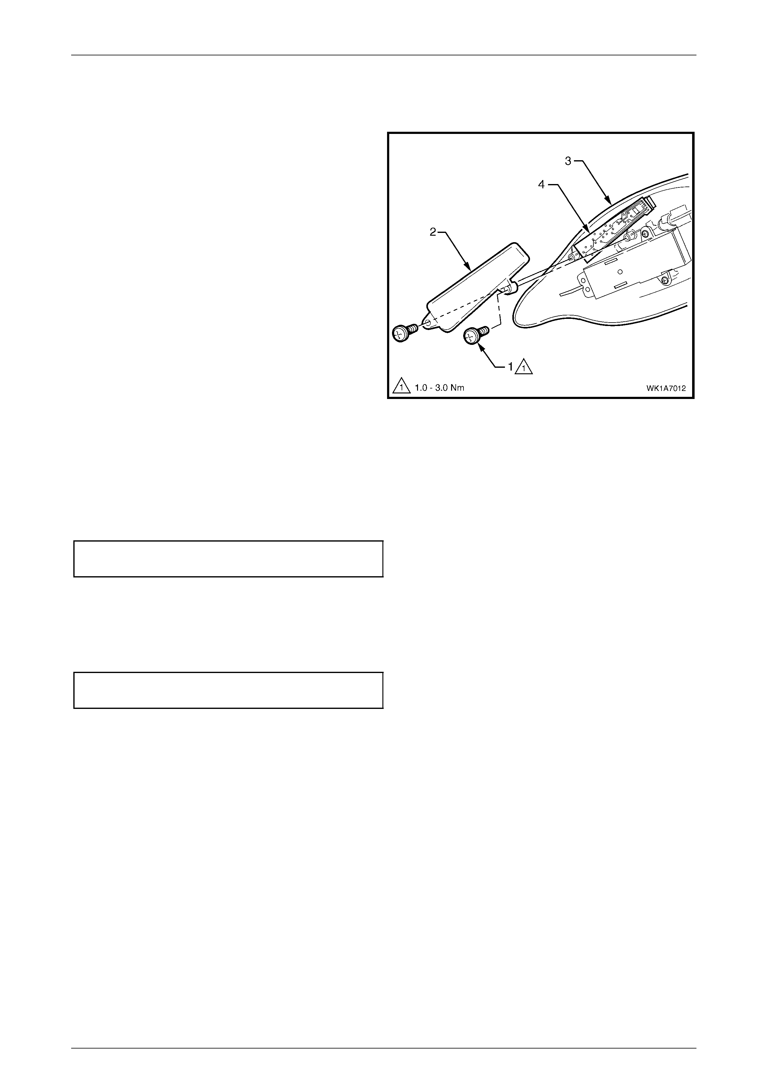
Seat Assemblies Page 1A7A–202
Page 1A7A–202
Memory Position Switch Assembly
Remove
1 Remove the screw (1) two places, attaching the
memory position switch cover (2) to the front seat
outer side cover (3).
2 Lift out the memory position switch assembly (4) from
its recess in the side cover.
3 As required, each position button can b e removed
from the switch.
Figure 1A7A – 51
Reinstall
Reinstallation of the memory position switch assembly is the reverse of the removal procedure, noting the following:
1 If removed, push the position buttons in until they click in place, ensuring correct orientation.
2 Tighten the attaching screws to the correct torque specification.
Memory position switch cover
attaching screw torque specification...........1.0 – 3.0 Nm
Reinstall
Reinstallation of the front seat outer side cover is the reverse of the removal procedure, noting the following:
1 Tighten the attaching screws to the correct torque specification.
Front seat outer side cover attaching
screw torque specification...........................1.0 – 3.0 Nm
2 If fitted, ensure the recliner knob is securely clipped in place.
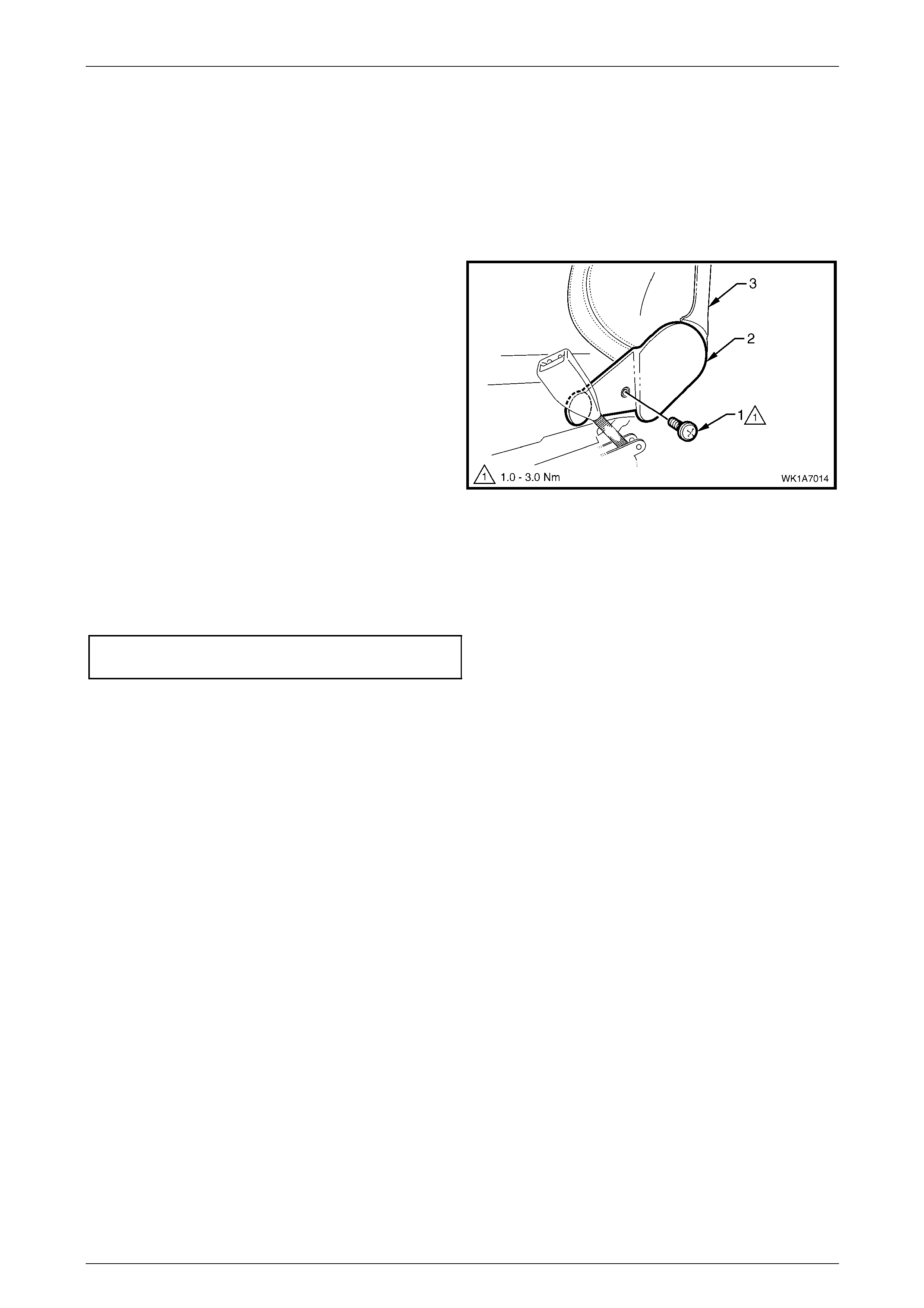
Seat Assemblies Page 1A7A–203
Page 1A7A–203
5.5 Front Seat Inner Side Cover
LT Section No. – 14-322
As required, remove the front seat assembly, refer to 5.3 Front Seat Assembly.
Remove
Remove the screw (1) attaching the front seat inner side
cover (2) to the seat assembly (3) and remove the cover.
Figure 1A7A – 52
Reinstall
Reinstallation of the front seat inner side cover is the reverse of the removal procedure, n oting the following:
Tighten the attaching screw to the correct torque specification.
Front seat inner side cover attachi ng
screw torque specification...........................1.0 – 3.0 Nm
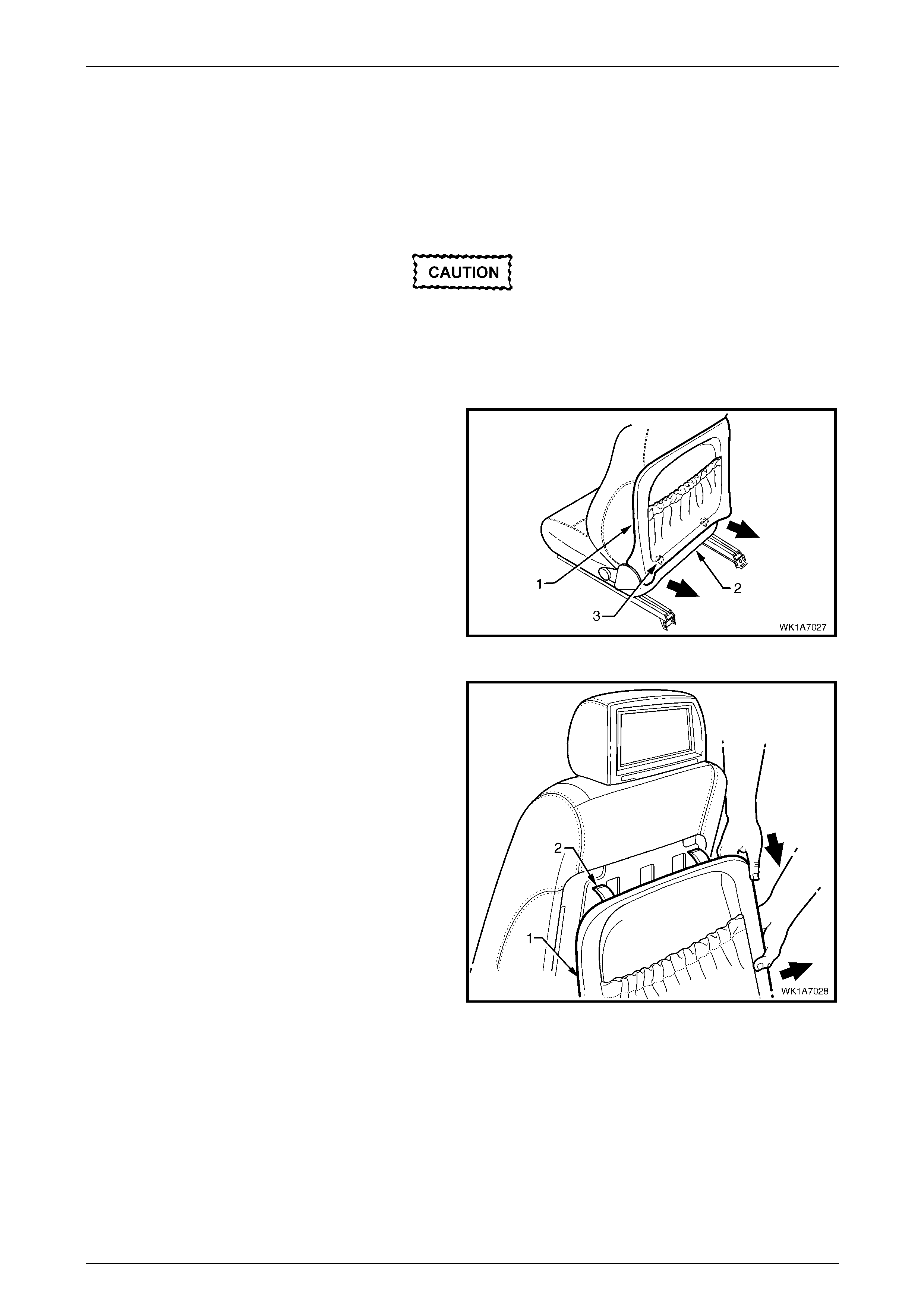
Seat Assemblies Page 1A7A–204
Page 1A7A–204
5.6 Front Seat-back Rear Cover Assembly
LT Section No. – 14-322
Remove
The following component will require
replacement when performing this operation.
• Front seat back rear cover retaining clip,
two places.
1 Pull the lower corners of the front seat-back rear cover
(1) away from the seat (2), breaking the two retaining
clips (3).
Figure 1A7A – 53
2 While holding the lower portion of the front seat-back
rear cover (1) out, pull the cover down to release the
upper retaining lug (2), t wo places.
3 Remove the cover.
Figure 1A7A – 54
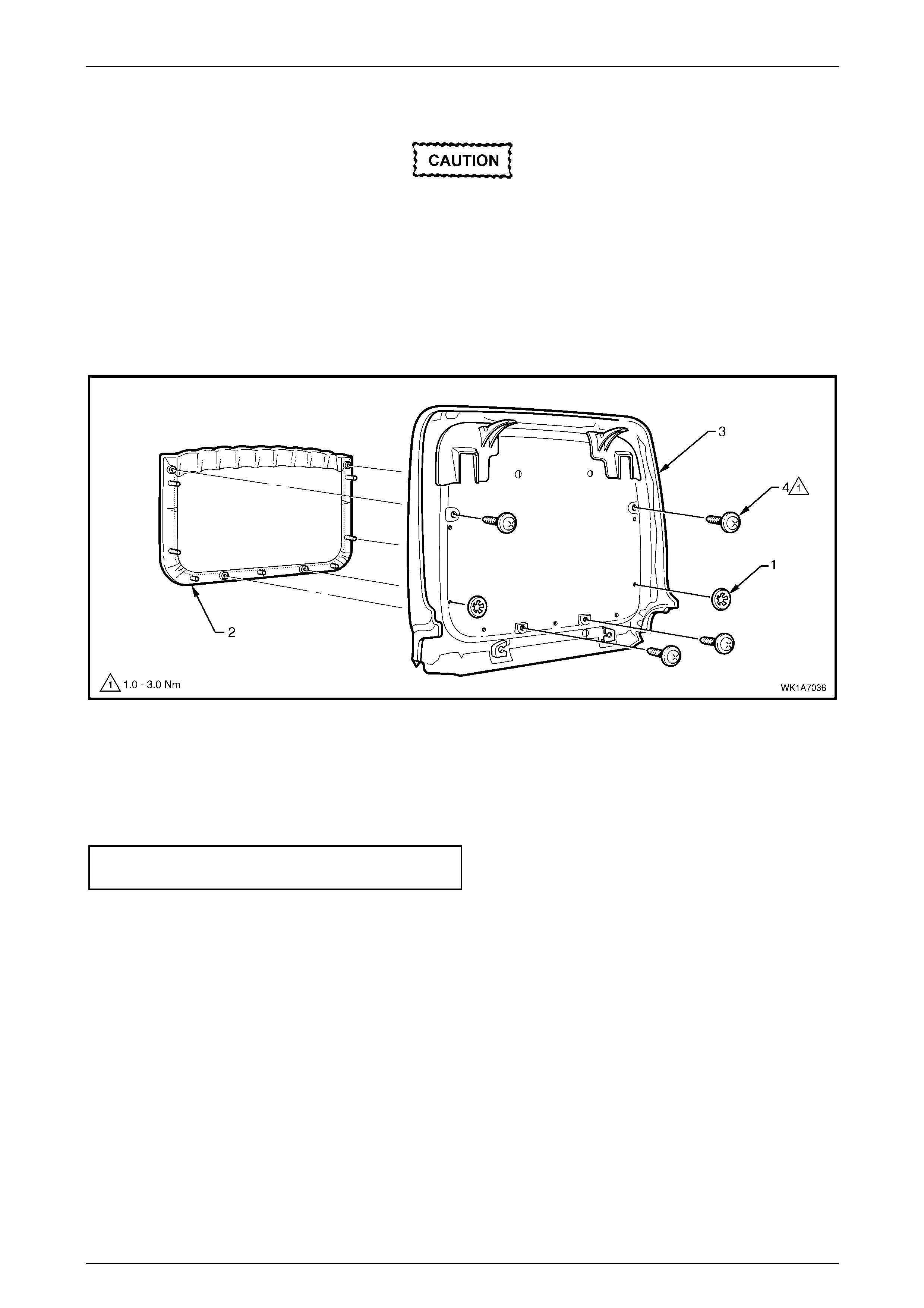
Seat Assemblies Page 1A7A–205
Page 1A7A–205
Disassemble
When performing Step 1, take care when
removing the retaining clip (1) not to break
the front seat-back map pocket shafts on
which the reta ining clips are attached.
1 Remove the two retaining clips (1) attaching the front seat-back map pocket (2) to the front seat-back rear cover
(3), refer to Figure 1A7A – 55.
2 Remove the four screws (4) attaching the map pocket to the cover.
3 Remove the map pocket.
Figure 1A7A – 55
Reassemble
Reassembly of the front seat-back rear cover is the reverse of the removal procedure, noting the following:
Tighten the attaching screws to the correct torque specification.
Front seat-back map pocket attaching
screw torque specification...........................1.0 – 3.0 Nm
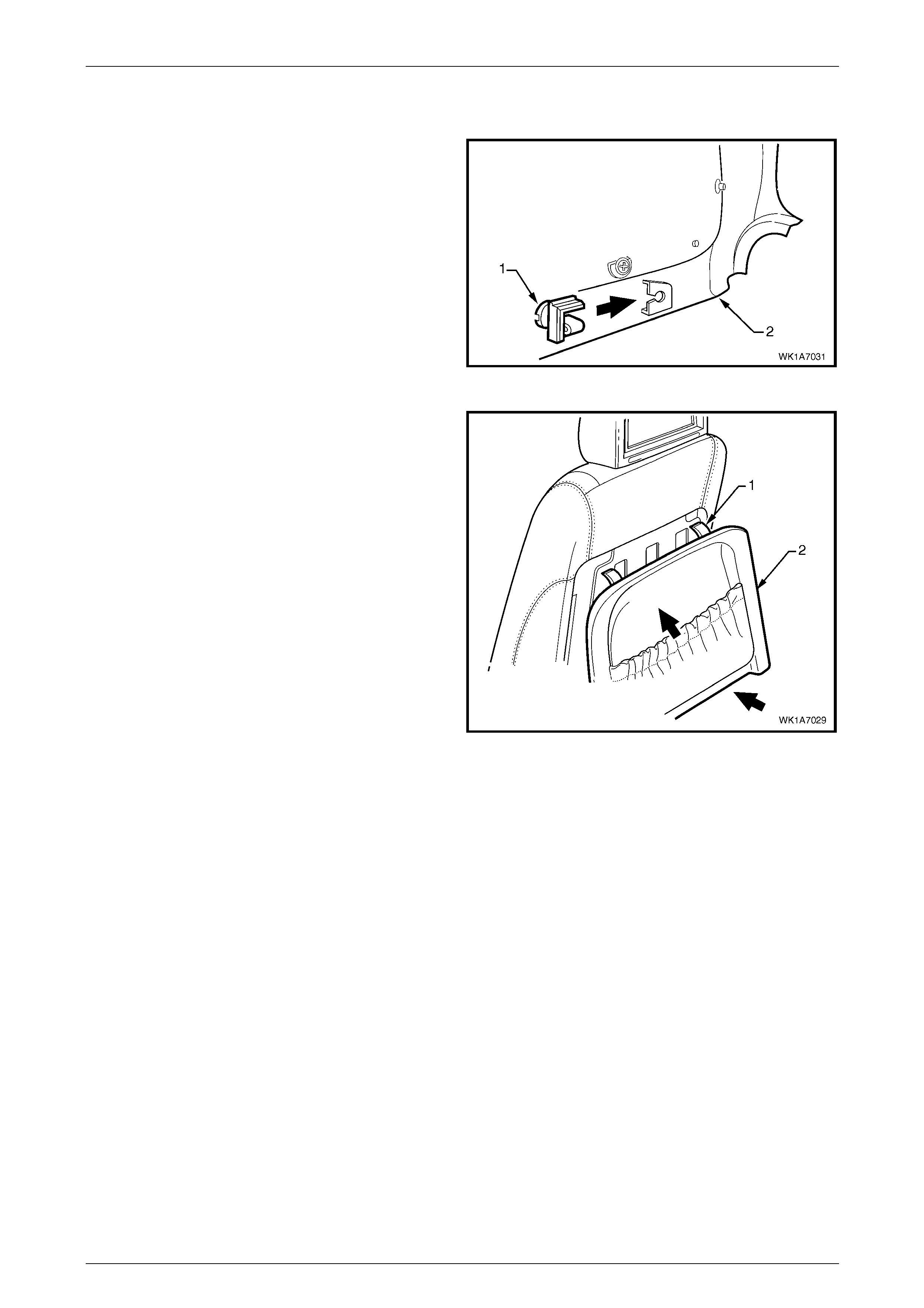
Seat Assemblies Page 1A7A–206
Page 1A7A–206
Reinstall
1 Replace the damaged retaining clip (1) on the front
seat-back rear cover (2), two places.
Figure 1A7A – 56
2 Align the two upper retaining l ugs (1) with the
seat-back.
3 Push the front seat-back rear cover (2) up and in at
the lower edge to engage the two lower retaining clips.
Figure 1A7A – 57

Seat Assemblies Page 1A7A–207
Page 1A7A–207
5.7 Front Seat Head Restraint Assembly
LT Section No. – 14-295
Front Seat Type 1, 2 & 5 to 12
Remove
1 Raise the head restraint fully.
2 Insert a suitable size probe into the hole (1) in the right-hand head restraint sleeve (2), refer to F igure 1A7A – 58
3 Push the probe in slightly whil e applying slight upward pressure on the head restraint. Hold the upward pressure.
4 Depress the head restraint sleeve height adjuster lock (3) on the left-hand head restraint sleeve and remove the
head restraint.
Figure 1A7A – 58
Disassemble
1 Disengage the front head restraint cover J-stri p by
pulling the flaps (1) back and out of flaps (2) in the
direction shown.
2 Carefully remove the cover from the pad assembly.
Figure 1A7A – 59
Reassemble
Reassembly of the front seat head restraint assembly is the reverse of the removal procedure, noting the following:
Ensure the head restraint cover J-clips are fully engaged.
Reinstall
Ensuring correct orientation of the head restraint, fit the head restraint shafts into the sleeves and push the head restraint
down.
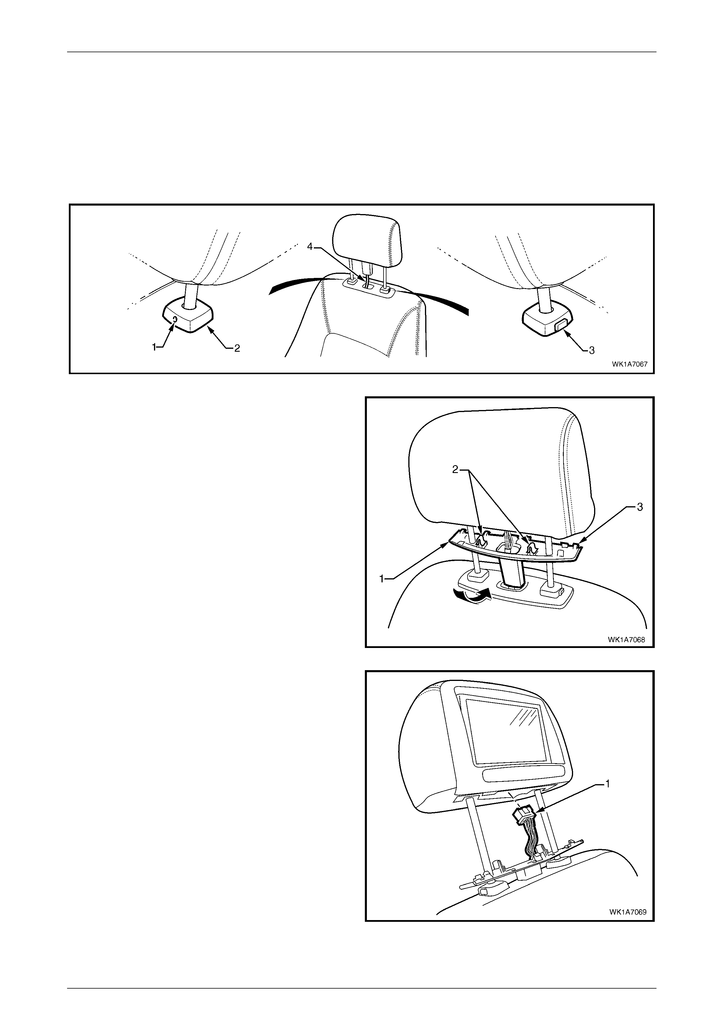
Seat Assemblies Page 1A7A–208
Page 1A7A–208
Front Seat Type 3, 4, 13 & 14
Remove
1 Raise the head restraint fully.
2 Insert a suitable size probe into the hole (1) in the right-hand head restraint sleeve (2), refer to F igure 1A7A – 60
3 Push the probe in slightly whil e applying slight upward pressure on the head restraint. Hold the upward pressure.
4 Depress the head restraint sleeve height adjuster lock (3) on the left-hand head restraint sleeve and raise the head
restraint as high as possible without placing undue strain on the rear seat entertainment lower wiring harness (4).
Figure 1A7A – 60
5 Carefully prise the front of the front head restraint
wiring cover (1) from the head restraint to disengage
the two retaining clips (2), rotating the cover rearward.
6 Detach the six rear retaining l ugs (3) and lower the
cover.
Figure 1A7A – 61
7 From below the head restraint, remove the rear seat
entertainment screen wiring connector (1) by
depressing its locking tab.
NOTE
A fine screwdriver may be needed to depress
the locking tab.
8 Remove the head restraint assembly and front head
restraint wiring cover.
Figure 1A7A – 62
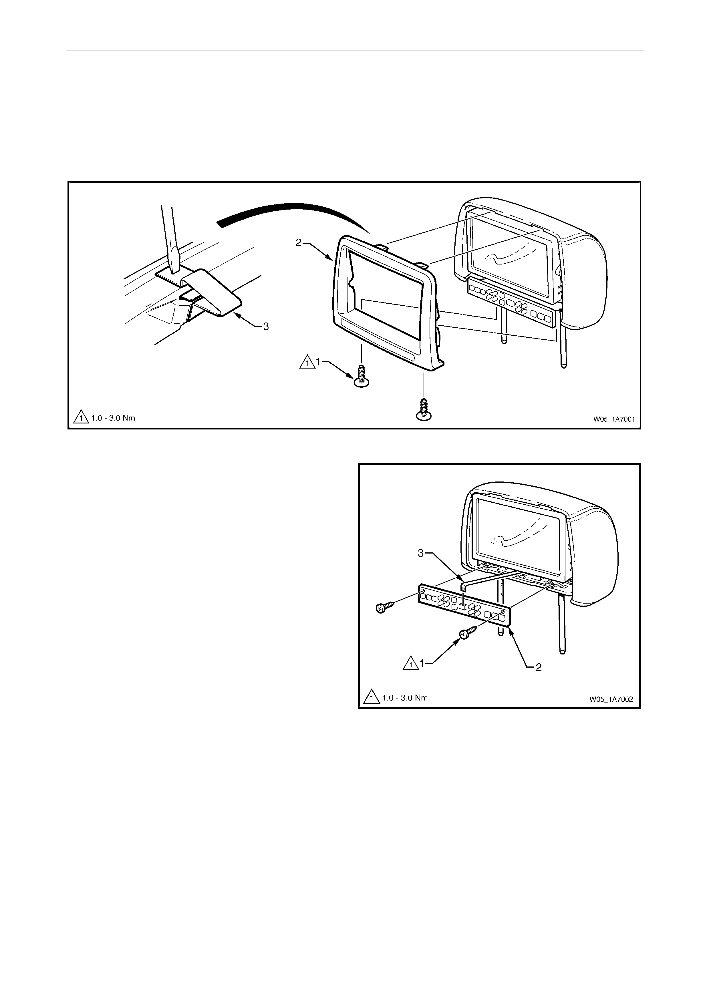
Seat Assemblies Page 1A7A–209
Page 1A7A–209
Disassemble
1 Remove the two screws (1), attaching the rear seat entertainment head rest escutcheon (2) to the head restraint
assembly, refer to Figure 1A7A – 63.
2 Using a fine, flat-blade screwdriver carefull y locate the retainin g clip (3) along the upper edge. Depress the clip and
detach the escutcheon slightly.
3 Repeat for the opposite retaining clip and remove the escutcheon.
Figure 1A7A – 63
4 Remove the two screws (1), attaching the rear seat
entertainment circuit board (2) to the head restraint
assembly.
5 Disconnect the ribbon wiring (3) from the circuit board.
6 Depress the retaining lug (1), four places, and remove
the rear seat entertainment screen bezel (2), refer to
Figure 1A7A – 65.
Figure 1A7A – 64
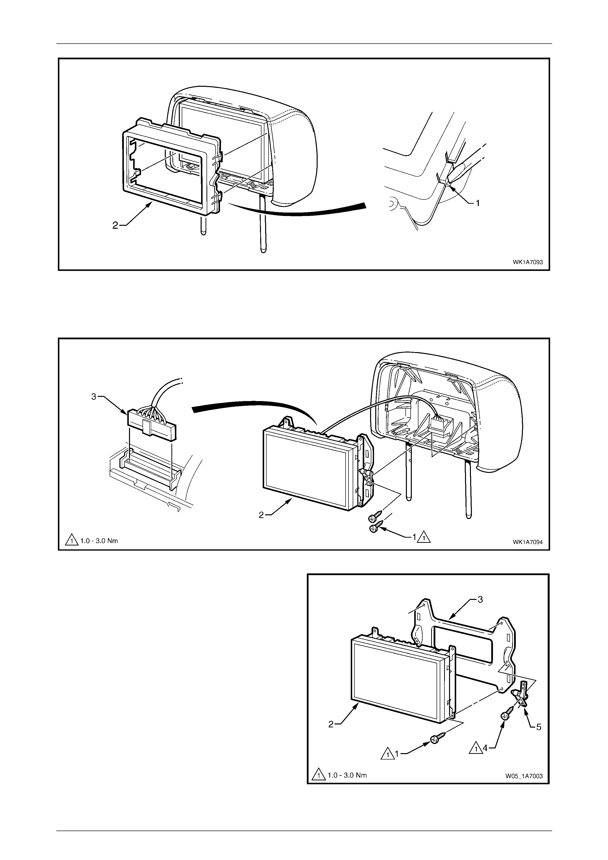
Seat Assemblies Page 1A7A–210
Page 1A7A–210
Figure 1A7A – 65
7 Remove the two screws (1) each side, attaching the rear seat entertai nment screen assembly (2) to the head
restraint assembly, refer to Figure 1A7A – 66.
8 Rotate the top of the screen assembly out, and from behind, carefully disconnect the wiring connector (3).
Figure 1A7A – 66
9 As required, remove the screw (1), four places,
attaching the rear seat entertainment screen (2) to the
mounting plate (3).
10 As required, remove the screw (4), two places,
attaching the pivot hinge (5) to the mounting plate.
11 Repeat for the opposite pivot hinge as re quired.
Figure 1A7A – 67
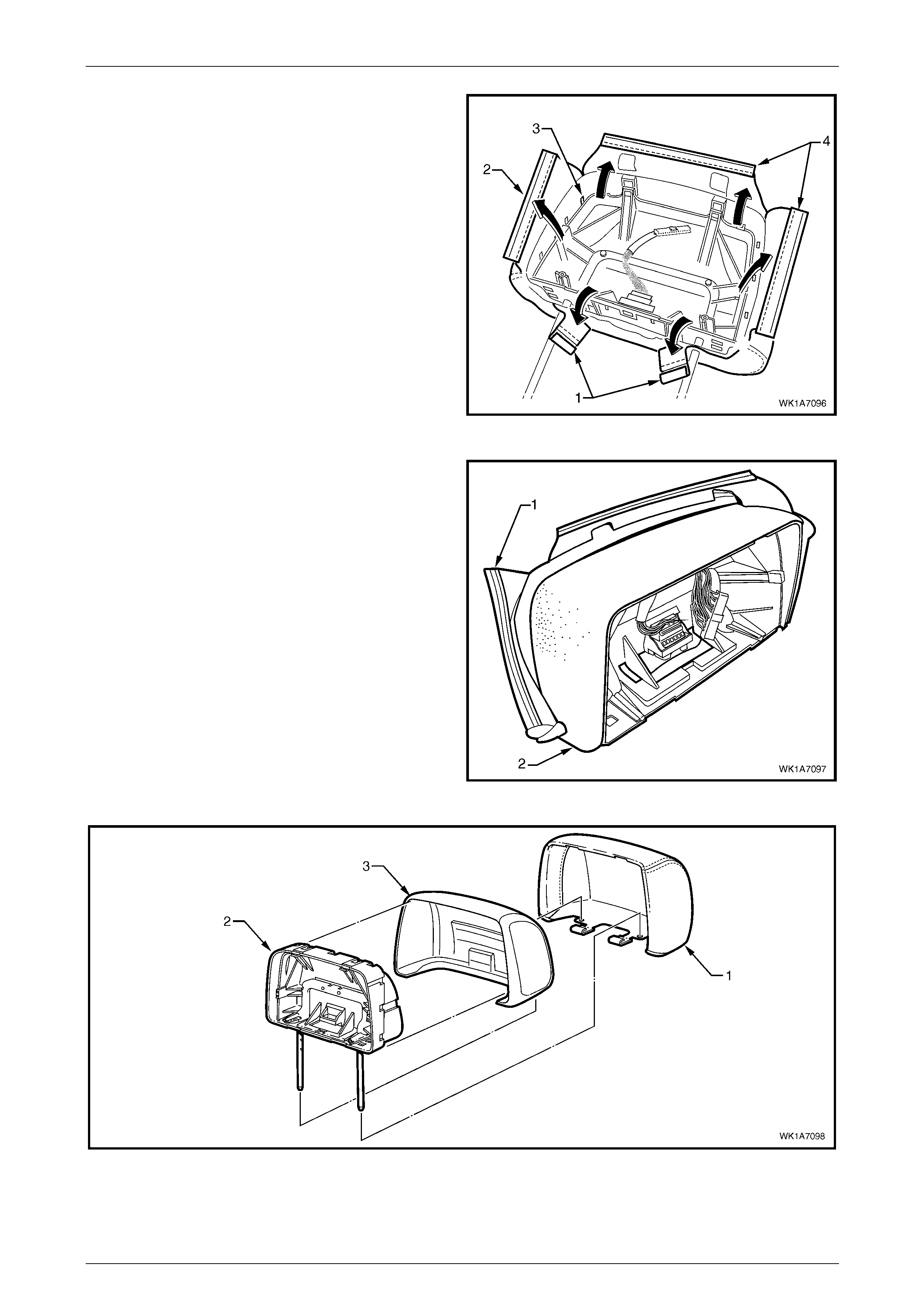
Seat Assemblies Page 1A7A–211
Page 1A7A–211
12 Disengage the two J-strips (1) attaching the head
restraint cover to the head restraint frame.
13 Using a fine, flat-blade screwdriver, prise the retaining
strip (2) from the three locking tabs (3) within the head
restraint frame recess.
14 Repeat for the two remaining strips (4).
Figure 1A7A – 68
15 Beginning at the upper corner, fold the head restraint
cover (1) from the head restraint pad (2).
16 Remove the cover (1) from the head restrain t frame
(2), refer to Figure 1A7A – 70.
17 Remove the pad (3) from the frame.
Figure 1A7A – 69
Figure 1A7A – 70

Seat Assemblies Page 1A7A–212
Page 1A7A–212
Reassemble
Reassembly of the front seat head restraint assembly is the reverse of the disassembly procedure, noting the following:
Tighten the attaching screws to the specifi ed torque.
Rear seat entertainment screen pivot
hinge attaching screw torque
specification................................................1.0 – 3.0 Nm
Rear seat entertainment screen
attaching screw torque specification...........1.0 – 3.0 Nm
Rear seat entertainment circuit board
attaching screw torque specification...........1.0 – 3.0 Nm
Rear seat entertainment head rest
escutcheon attaching screw torque
specification................................................1.0 – 3.0 Nm
Reinstall
Reinstallation of the front seat head restraint assembly is the reverse of the removal proc edure noting the following:
1 Place the front head restraint wiring cover in position on the seat-back, feedin g the r ear seat entertainment lower
wiring harness through the ca vity and ensuring the cover is correctly orientated.
2 Place the head restraint assembly in position in the h ead restraint sleeves, connect the wiring harness and clip the
wiring cover in place.

Seat Assemblies Page 1A7A–213
Page 1A7A–213
5.8 Front Seat Head Restraint Sleeve
As required, remove the front seat head restraint assembl y, refer to 5.7 Front Seat Head Restrai nt Assembl y.
LT Section No. – 14-275
Front Seat Type 1, 2 & 5 to 12
Remove
1 Push down on the surrounding seat cover to reveal the
upper portion of the seat-back frame or active head
restraint frame (1).
2 Using a fine flat-blade screwdriver, depress the head
restraint sleeve retaining lug (2) and withdraw the
head restraint sleeve (3) from the frame.
3 Repeat for the remaining sleeve as required.
Figure 1A7A – 71
Reinstall
Reinstallation of the front seat head restraint sleeve is the reverse of the removal proce dure, noting the following:
NOTE
Ensure the sleeve with the height adjuster lock
(1) is installed on the left-hand side of the seat;
that is the side that corresponds to the lower
square notch (2) in the head restraint shaft.
Figure 1A7A – 72
1 Align the head restraint sleeve locatin g ribs (1 ) with
the notch (2) in the seat-back frame.
2 Insert the sleeve and ensure it clicks into place.
Figure 1A7A – 73
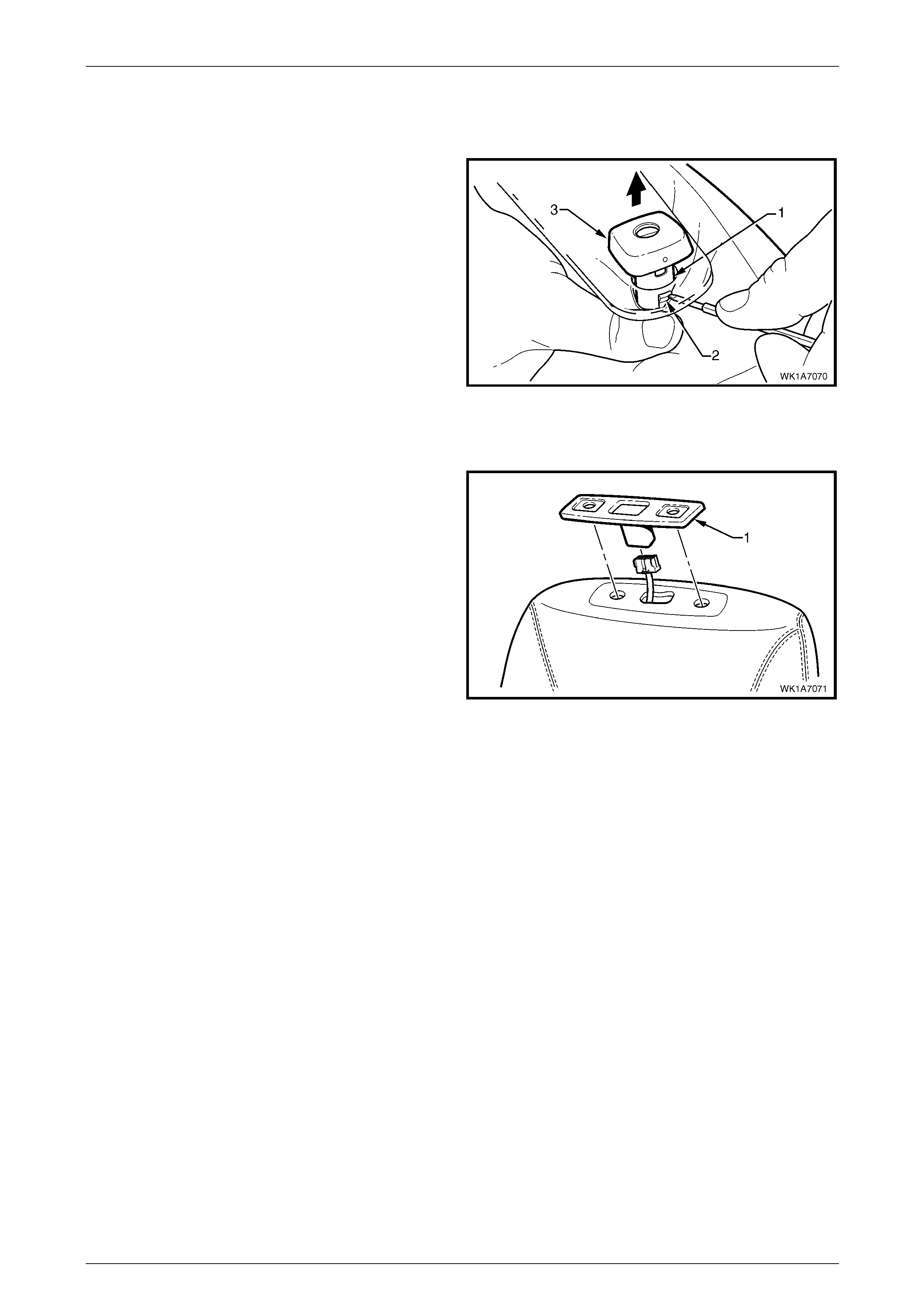
Seat Assemblies Page 1A7A–214
Page 1A7A–214
Front Seat Type 3, 4, 13 & 14
Remove
1 Push down on the surrounding seat cover to reveal the
upper portion of the active head restraint frame (1)
below the front seat head restraint guide cover.
NOTE
If the front seat-back rear cover has
been removed, have an assistant pull on the
active head restraint strap to raise the
sleeves. Do not remove the rear cover
unless necessary as the retaining clips will
break requiring replacement, refer to
5.6 Front Seat-back Rear Cover Assembly.
2 Using a fine flat-blade screwdriver, depress the head
restraint sleeve retaining lug (2) and withdraw the
head restraint sleeve (3) from the frame.
3 Repeat for the remaining sleeve as required.
Figure 1A7A – 74
4 Lift off the front seat head restraint guide cover (1).
Figure 1A7A – 75
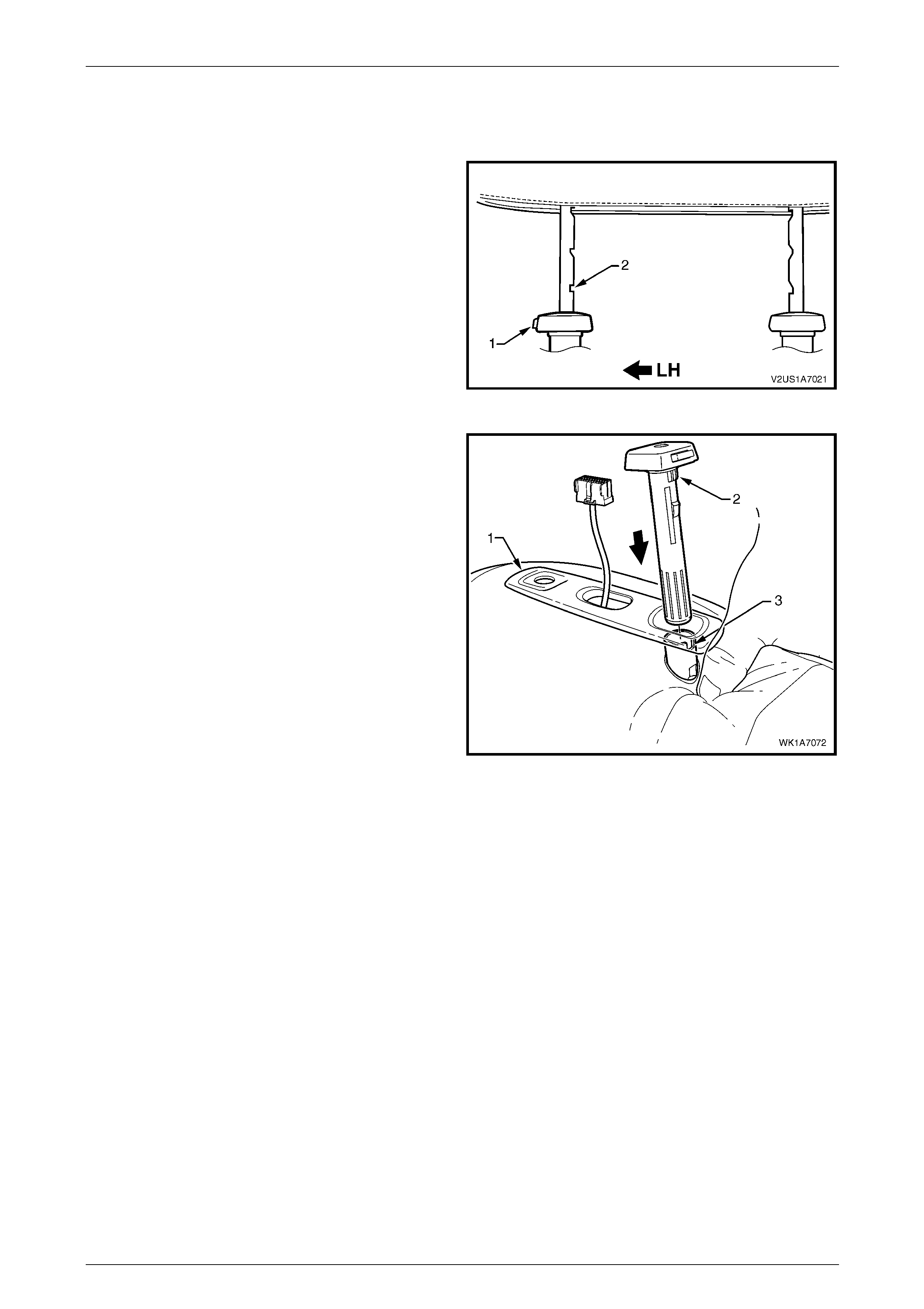
Seat Assemblies Page 1A7A–215
Page 1A7A–215
Reinstall
Reinstallation of the front seat head restraint sleeve is the reverse of the removal proce dure, noting the following:
NOTE
Ensure the sleeve with the height adjuster lock
(1) is installed on the left-hand side of the seat;
that is the side that corresponds to the lower
square notch (2) in the head restraint shaft.
Figure 1A7A – 76
1 Feed the rear seat entertainment lower wiring harness
assembly through the front seat head restraint guide
cover (1) and fit the cover in position.
2 Align the head restraint sleeve locatin g ribs (2 ) with
the notch (3) in the seat-back frame.
3 Insert the sleeve and ensure it clicks into place.
Figure 1A7A – 77
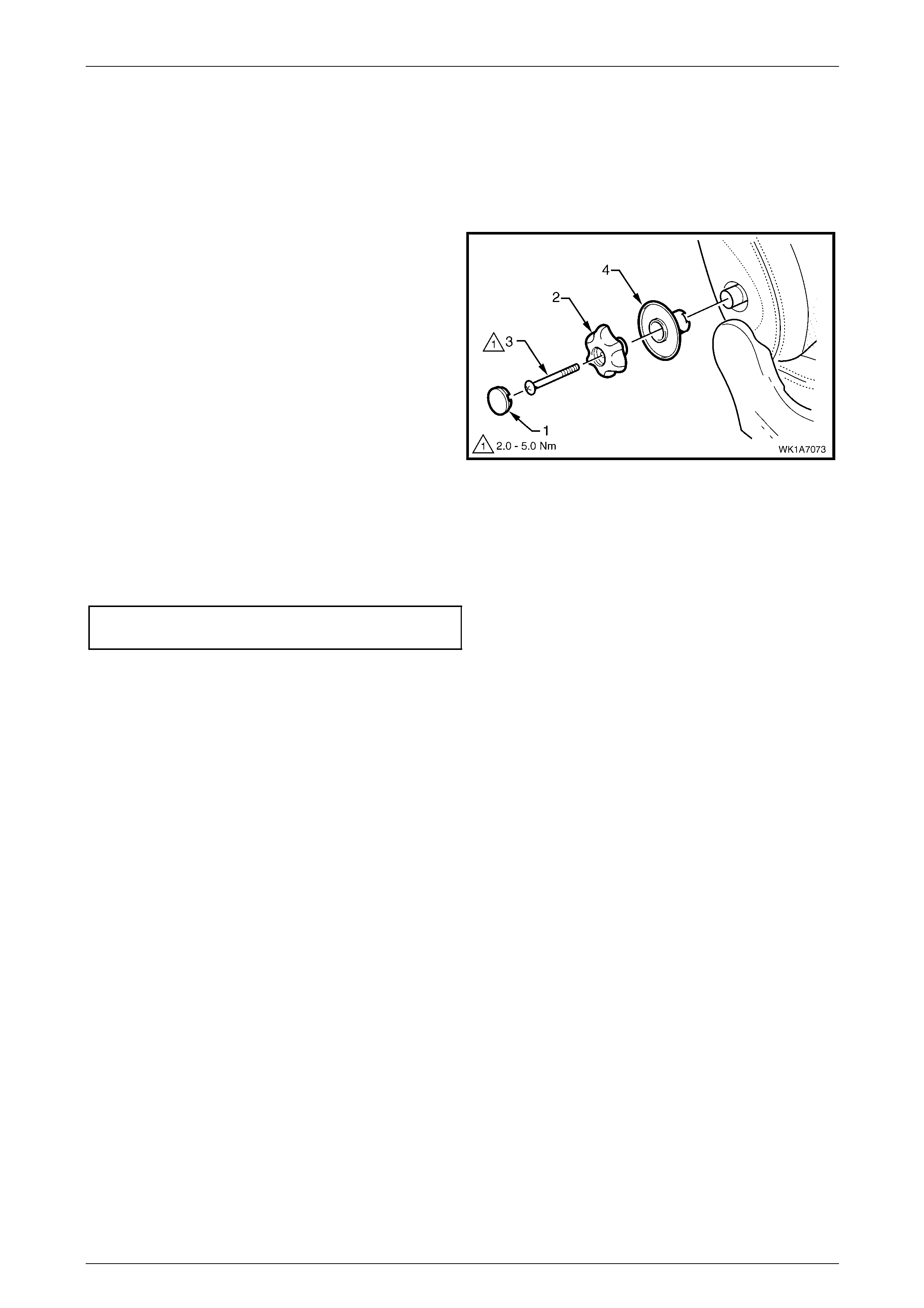
Seat Assemblies Page 1A7A–216
Page 1A7A–216
5.9 Lumbar Support Knob Assembly
LT Section No. – 14-275
Remove
1 Ensure the lumbar support is in the full off position.
2 Using a fine flat-blade scre w-driver, carefull y prise the
cap (1) from the lumbar support knob (2).
3 Remove the screw (3) attaching the knob to the
lumbar support shaft.
4 Pull the knob off the lumbar support shaft and remove
the lumbar support deflector ring (4).
NOTE
The knob is lightly clipped to the lumbar support
shaft and will ‘click-off’.
Figure 1A7A – 78
Reinstall
Reinstallation of the lumbar s upport knob assembly is the reverse of the removal proced ure, noting the following:
Tighten the attaching screw to the correct torque specification.
Lumbar support knob attachin g
screw torque specification...........................2.0 – 5.0 Nm
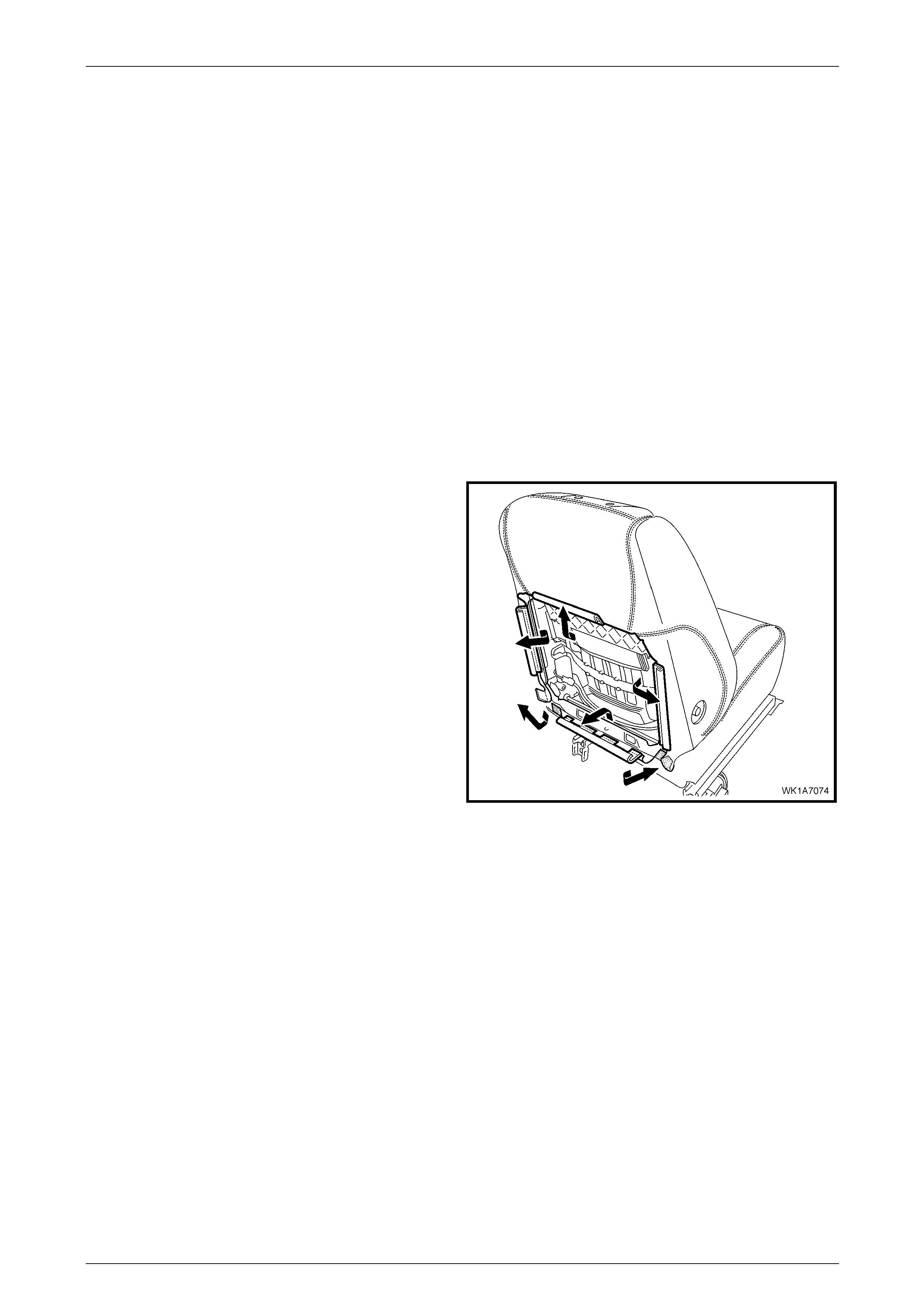
Seat Assemblies Page 1A7A–217
Page 1A7A–217
5.10 Front Seat-back Pad and Cover
Assembly
LT Section No. – 14-295
As required, remove the following compo nents:
1 Front seat assembly, refer to 5.3 Front Seat Assembly.
2 Front seat outer side cover assembly, refer to 5.4 Front Seat Outer Side Cover Assembly.
3 Front seat inner side cover, refer to 5.5 Front Seat Inner Side Cover.
4 Front seat-back rear cover assembly, refer to 5.6 Front Seat-back Rear Cover Assemb ly.
5 Front seat head restraint assembly, refer to 5.7 Front Seat Head Restraint Assembly.
6 Front seat head restraint sleeves, refer to 5.8 Front Seat Head Restraint Sleeve.
7 Lumbar support knob assembly, refer to 5.9 Lumbar Suppor t Knob Assembly.
Remove
1 Disengage the J-strips from the seat frame a nd the
Velcro tab at each lower corner.
2 Lift the cover and pad assembly up and away from the
seat-back frame, manoeuvring it over the seat-back
components such as the side impact airbag a nd
dummy block insert assemblies.
Figure 1A7A – 79
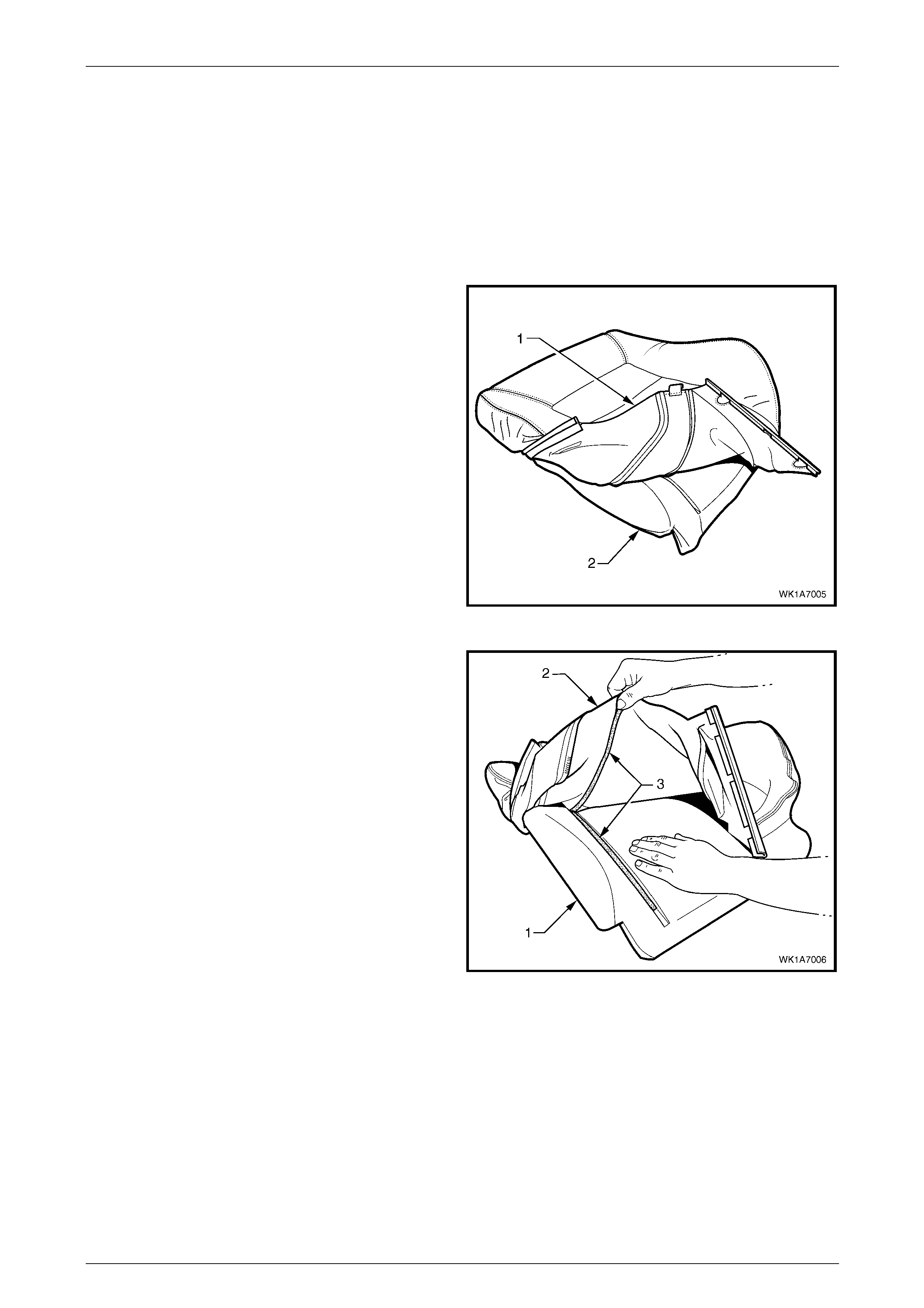
Seat Assemblies Page 1A7A–218
Page 1A7A–218
Disassemble
NOTE
The following illustrations show typical hook and
loop arrangement, which will vary according to
seat type.
Surebond type seat-back cover and pad
assemblies cannot be disassembled.
1 Fold the lower corners of the seat-back cove r (1) over
the seat-back pad (2).
Figure 1A7A – 80
2 While holding the front seat-back pad (1), pull the
lower corners of the seat-back cover (2), upwards and
away from the front seat pad to disengage the hook
and loop strips (3).
3 Pull the front seat-back cover up and over the upper
edge of the front seat-back pad.
Figure 1A7A – 81
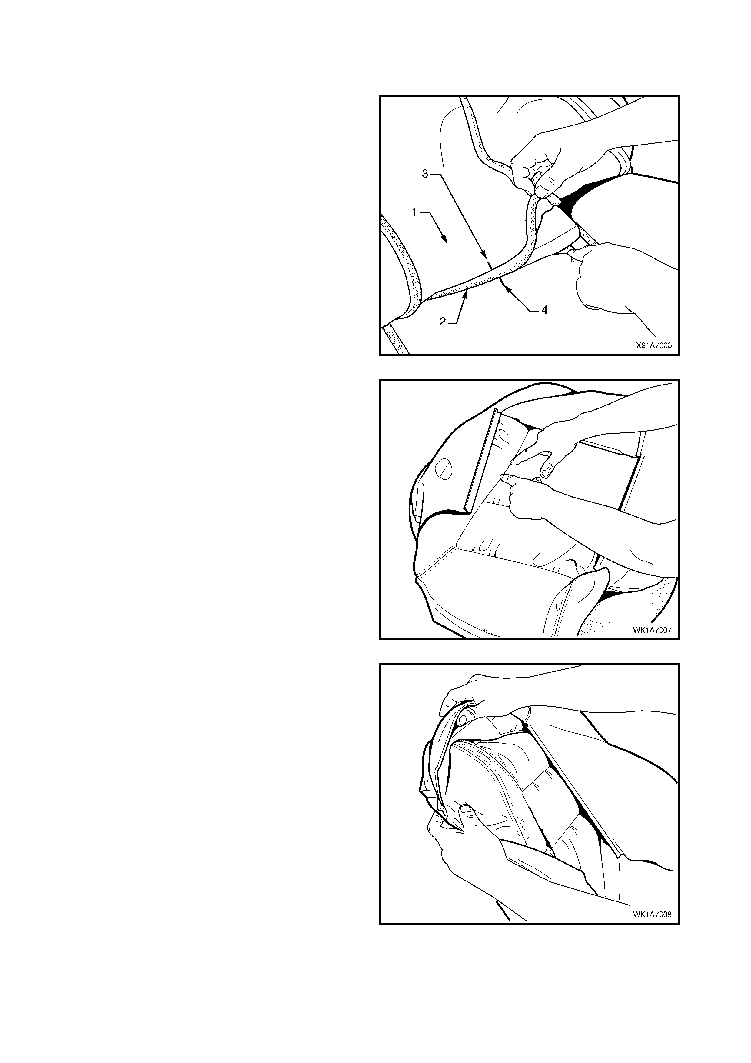
Seat Assemblies Page 1A7A–219
Page 1A7A–219
Reassemble
1 With the seat-back cover (1) folded at the central
horizontal strip of hook and loop (2), align th e centre
mark (3) on the cover with the centre mark (4) on the
front seat-back pad.
2 Press the cover firmly into the corresponding groove i n
the seat-back pad to engage the hook and loop.
Figure 1A7A – 82
3 With the cover folded at the two vertical strips of the
hook and loop, press the cover firml y into the
corresponding grooves in the pad.
Figure 1A7A – 83
4 Roll the upper corners of the cover over the pad.
5 Roll the sides of the cover over the pad.
6 Roll the lower corners of the cover over the pad.
NOTE
Make sure the cover is fitted neatly by hand into
all corners and contours of the seat pad.
Figure 1A7A – 84
Reinstall
Reinstallation of the front seat -back pad and cover assembly is the reverse of the removal procedure.
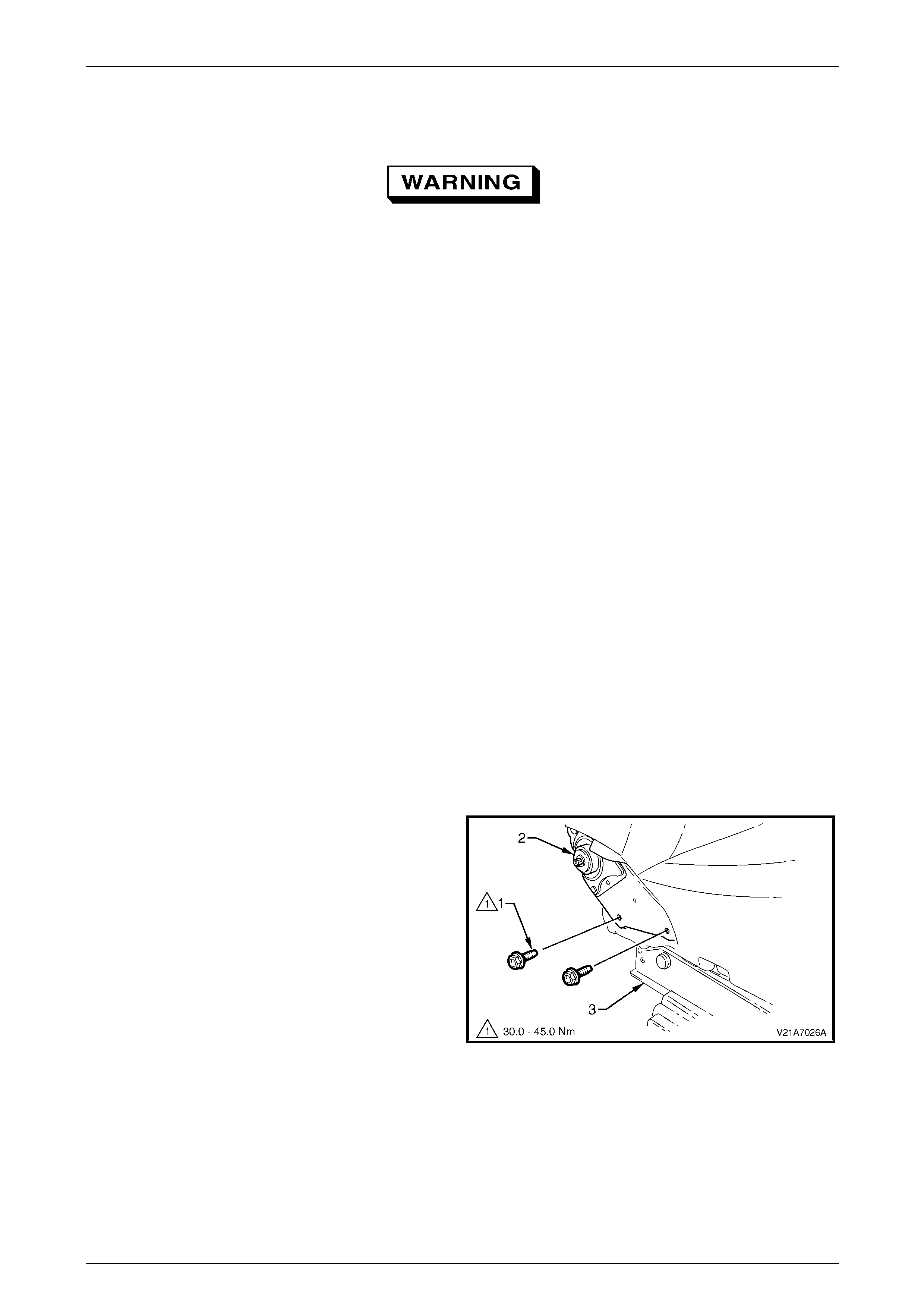
Seat Assemblies Page 1A7A–220
Page 1A7A–220
5.11 Front Seat-back Frame Assembl y
When carrying a live (undeployed) side
impact airbag assembly or a front seat-back
frame assembly fitted with a (undeployed)
side impact airbag assembly, ensure the
airbag opening is pointed away from you.
Never carry the side impact airbag assembly
or seat-back frame assembly fitted w ith a side
impact airbag assembly by the airbag wiring
harness or connectors. In case of an
accidental deployment, the airbag will then
deploy with minimal chance of injury.
When placing a live side impact airbag
assembly or a fro nt seat-ba ck frame as sembly
fitted with a (undeployed) side impact airbag
assembly on a bench or other surface, always
face the airbag opening up, away from the
surface. Never rest the airbag assembly or
seat-back frame with the airbag opening face
down. This is necessary so that a free space
is provided to allow the airbag to expand in
the unlikely event of accidental deployment.
Otherwise, personal injury may result.
LT Section No. – 14-275
As required remove the following c ompo nents:
1 Front seat assembly, refer to 5.3 Front Seat Assembly.
2 Front seat outer side cover assembly, refer to 5.4 Front Seat Outer Side Cover Assembly.
3 Front seat inner side cover, refer to 5.5 Front Seat Inner Side Cover.
Remove
1 Remove the two screws (1), each side, attaching the
seat-back assembly (2) to the front seat cushion frame
assembly (3).
2 As required, disconnect and detach the front seat-back
recline motor, side impact airbag a nd DVD display
wiring harnesses.
3 Remove the seat-back assembly.
Figure 1A7A – 85
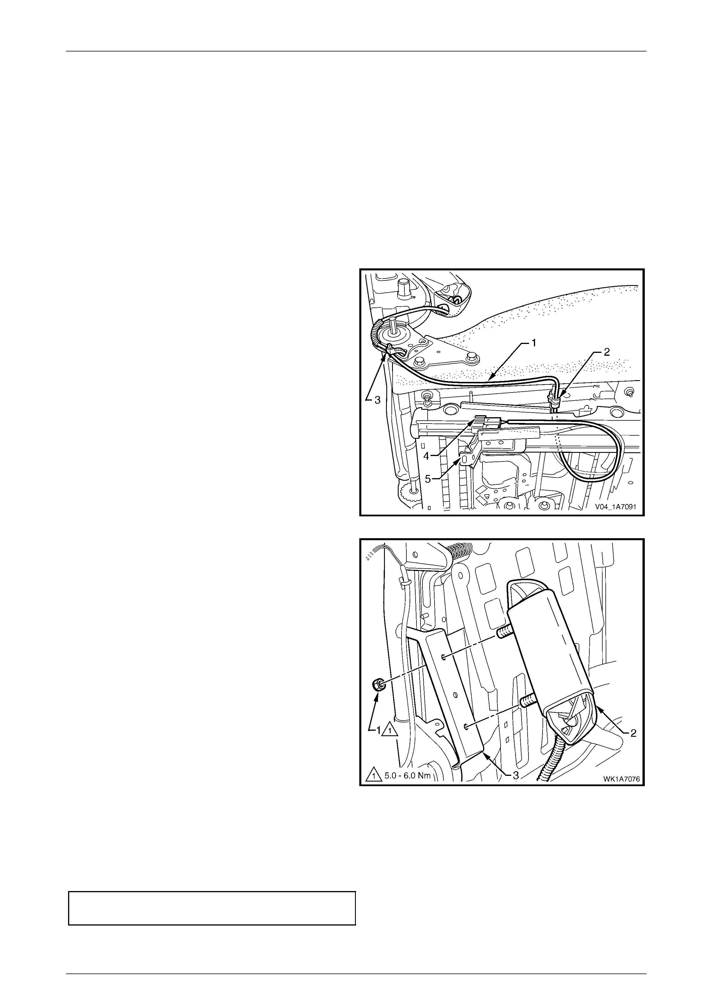
Seat Assemblies Page 1A7A–221
Page 1A7A–221
Disassemble
As required, remove the following compo nents:
1 Front seat-back rear cover assembly, refer to 5.6 Front Seat-back Rear Cover Assemb ly.
2 Front seat head restraint assembly, refer to 5.7 Front Seat Head Restraint Assembly.
3 Front seat head restraint sleeves, refer to 5.8 Front Seat Head Restraint Sleeve.
4 Lumbar support knob assembly, refer to 5.9 Lumbar Suppor t Knob Assembly.
5 Front seat-back pad and cover assembl y, refer to 5.10 Front Seat-back Pad and Cover Assembly.
Side Impact Airbag Assembly
Remove
1 As required, unclip the side im pact airbag wiring
harness (1) from the retaining clip (2) and cut the two
cable ties (3), securing the harness to the front seat
cushion frame assembly, taking care not to damage
the wiring harness.
2 Unclip the wiring harness connector (4) from the track
and height adjust assembly (5).
Figure 1A7A – 86
3 Remove the lock-nut (1), two places, attaching the
side impact airbag assembl y ( 2) to the seat-b ack
frame (3) and airbag assembly.
Figure 1A7A – 87
Reinstall
Reinstallation of the side impact airba g asse mbly is the reverse of the removal procedure, noting the following:
1 Ensure the conduit covering the wiring harness and the harness are pos itioned correctly, refer to Figure 1A7A – 86.
2 Tighten the attaching nuts to the correct torque specification.
Side impact airbag assembly attaching
nut torque specification...............................5.0 – 6.0 Nm
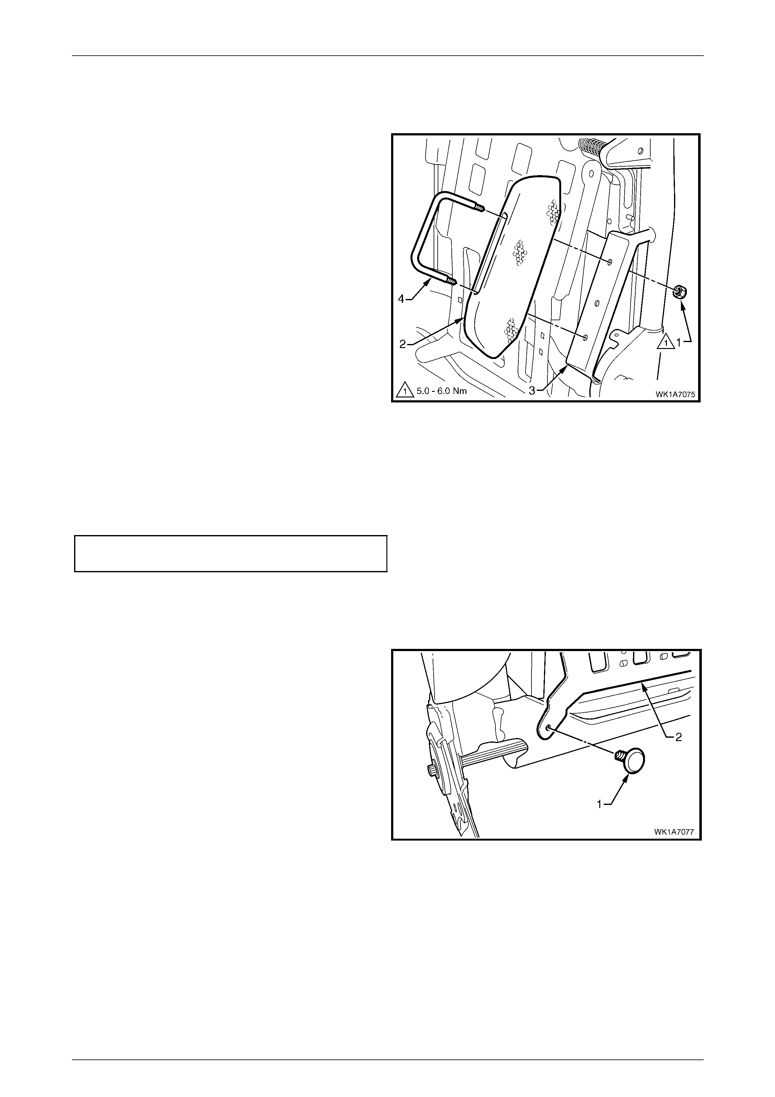
Seat Assemblies Page 1A7A–222
Page 1A7A–222
Front Seat Dummy Block Insert Assembly
Remove
1 Remove the lock nut (1), two places, attaching the
front seat dummy block insert (2) to the seat-back
frame (3) and remove the dummy block insert
assembly.
2 If required, remove the dummy block U-bolt (4) from
the dummy block insert.
Figure 1A7A – 88
Reinstall
Reinstallation of the front seat dummy block insert assembly is the reverse of the removal procedure, noting the
following:
Tighten the attaching nuts to the correct torque spec ification.
Front seat dummy block insert attaching
nut torque specification...............................5.0 – 6.0 Nm
Lumbar Support Assembly
Remove
1 Remove the retainer (1), two places, attaching the
lumbar support assembly (2) to the seat-back frame.
Figure 1A7A – 89
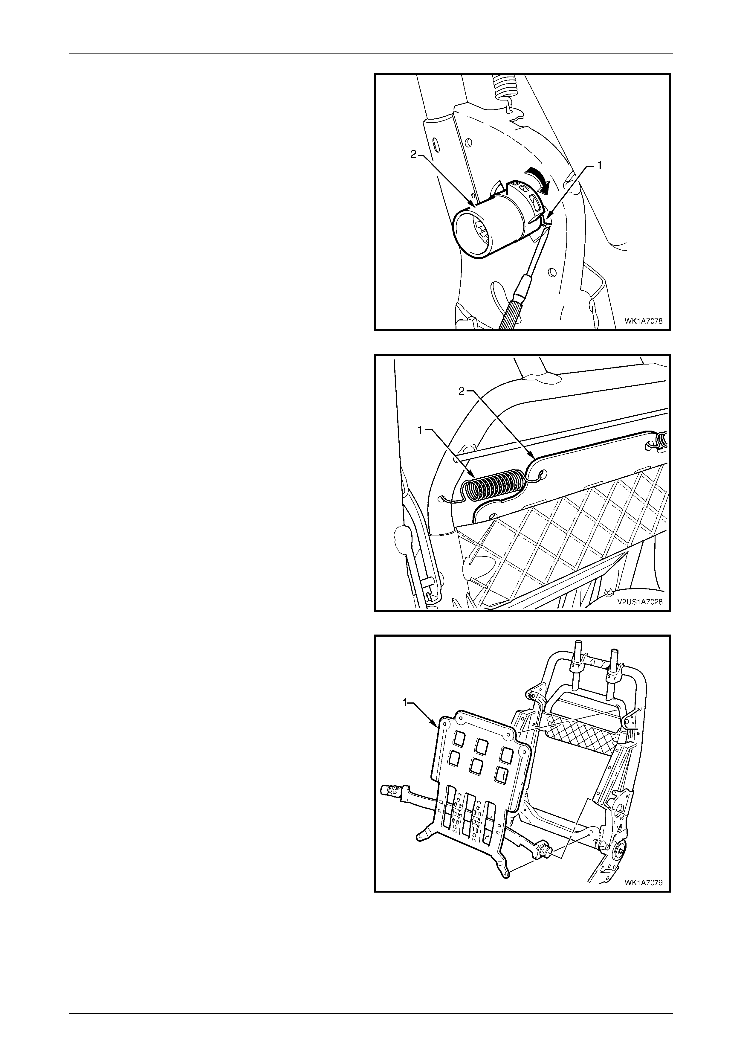
Seat Assemblies Page 1A7A–223
Page 1A7A–223
2 Depress the retaining tab (1) and from the inner side
of the seat-back frame, rotate the lumbar support shaft
(2) and withdraw from the seat-back frame.
3 Repeat for the opposite side.
Figure 1A7A – 90
4 Disconnect the spring (1), two places, attaching the
lumbar support assembly (2) to the seat-bac k frame or
active head restraint frame.
TIP
To aid spring remova l, pull the support asse mbly
toward the side that the spring is being remove d
to relieve spring tension.
Figure 1A7A – 91
5 Remove the lumbar support assembly (1).
Figure 1A7A – 92
Reinstall
Reinstallation of the lumbar s upport assembly is the reverse of the removal procedure, n oting the following:
Ensure the lumbar support assembl y is correctly seated on the cushion side of the active head restraint frame, where
fitted, with the black lumbar support shaft on the outer side of the seat.
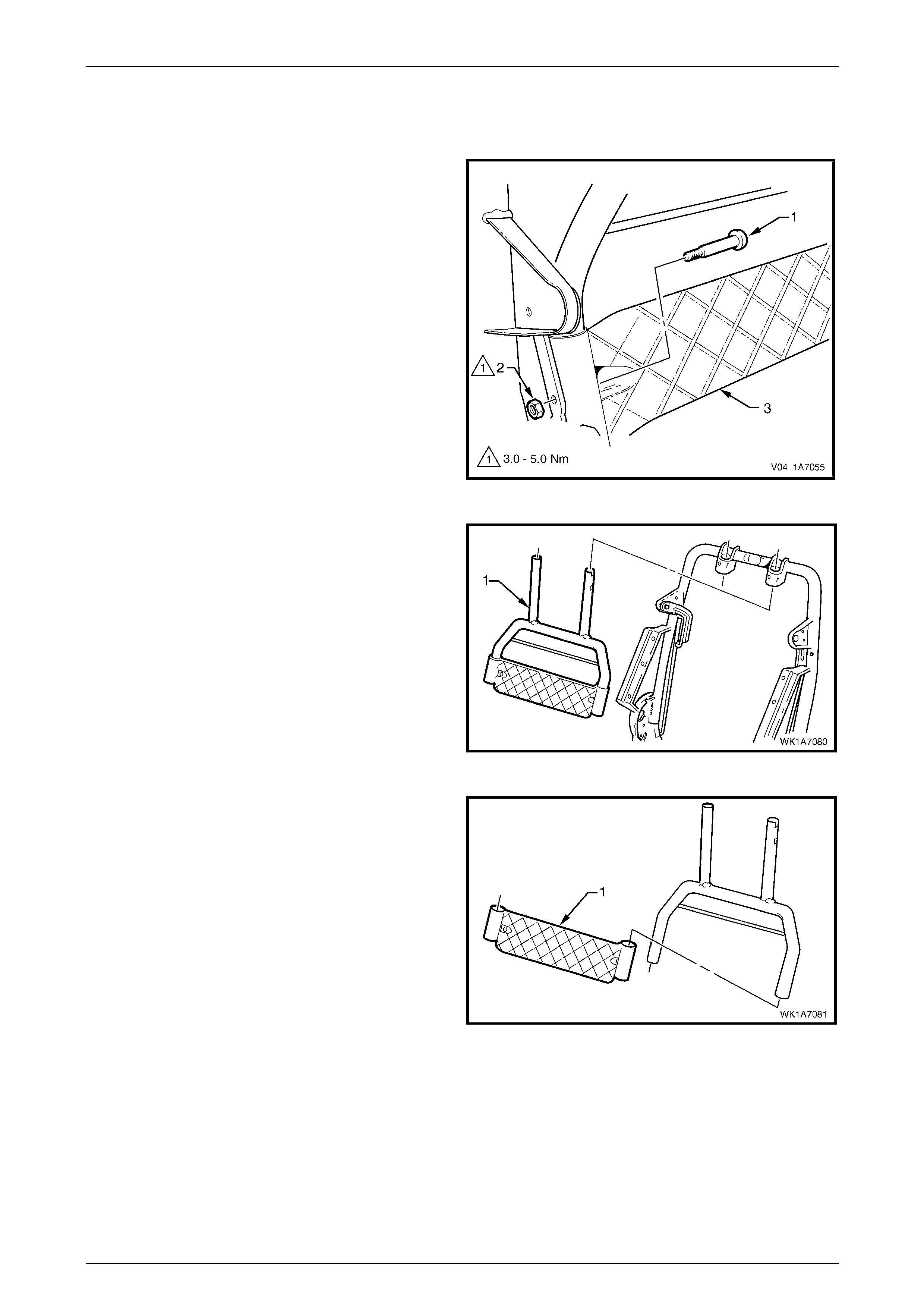
Seat Assemblies Page 1A7A–224
Page 1A7A–224
Active Head Restraint Frame Assembly
Remove
1 Remove the screw (1) and nut (2), two places,
attaching the active head restraint frame assembly (3)
to the seat-back frame hinge.
Figure 1A7A – 93
2 Withdraw the active head restraint frame assembly (1)
downward to remove it from the seat-back frame and
remove.
Figure 1A7A – 94
3 If required, slide the support strap (1) from the active
head restraint frame.
Figure 1A7A – 95
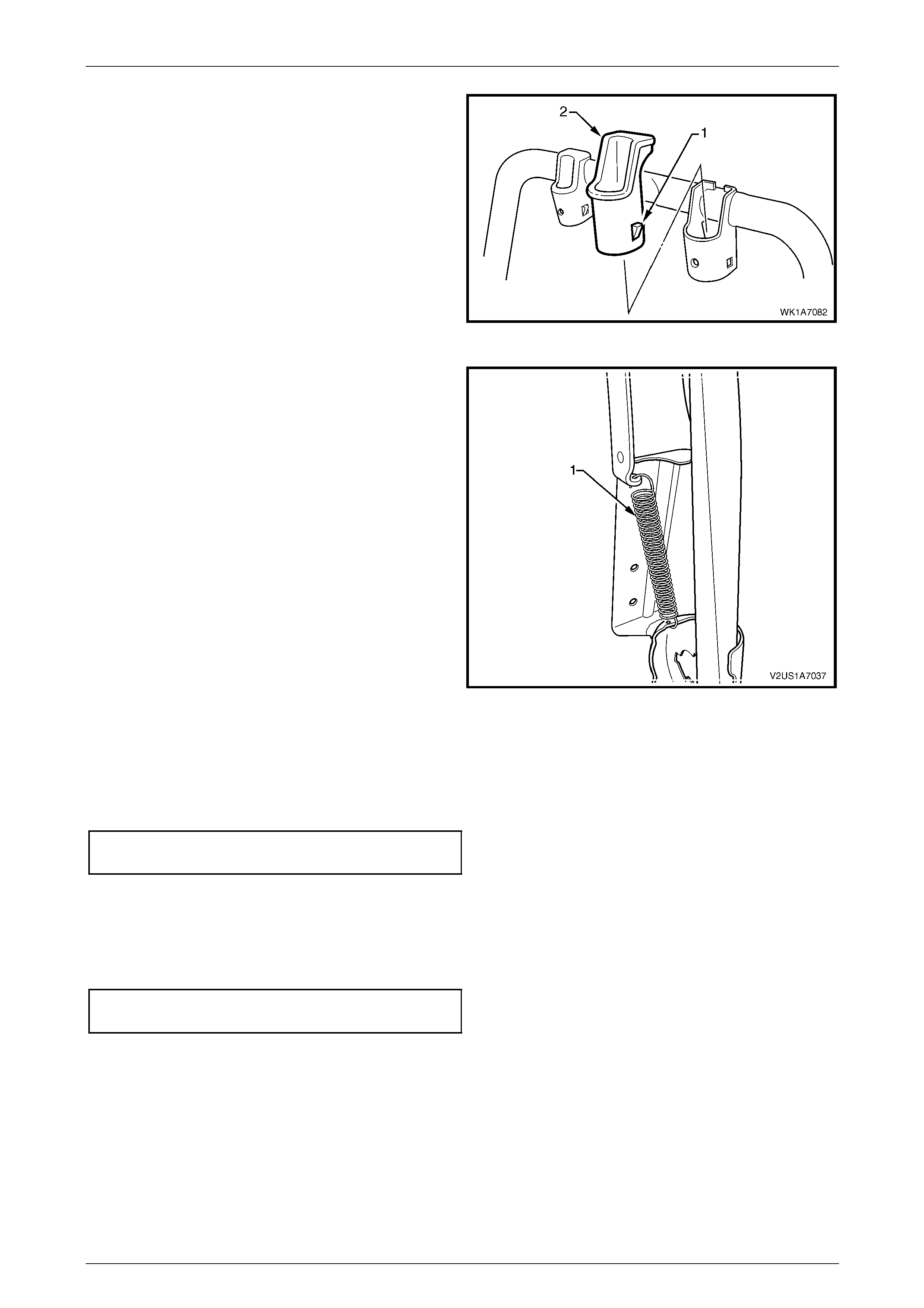
Seat Assemblies Page 1A7A–225
Page 1A7A–225
4 If required, depress the tab (1), two places, and
withdraw the active head restraint frame sleeve (2)
from the seat-back frame.
5 Repeat for the opposite sleeve as requ ired.
Figure 1A7A – 96
6 If required, remove the spring (1), from the active head
restraint frame hinge and seat-back frame.
7 Repeat for the opposite side as required.
Figure 1A7A – 97
Reinstall
Reinstallation of the active head restraint frame assembly is the reverse of the removal procedure, noting the following:
Tighten the attaching nuts to the correct torque spec ification.
Active head restraint frame assembly
attaching nut torque specification................3.0 – 5.0 Nm
Reinstall
Reinstallation of the front seat-back frame assembly is the reverse of the removal proced ure, noting the following:
1 Tighten the attaching screws to the correct torque specific ation.
Front seat-back frame assembly
attaching screw torque specification.......30.0 – 45.0 Nm
2 Check the mechanical and ele c trical operation of the front seat.
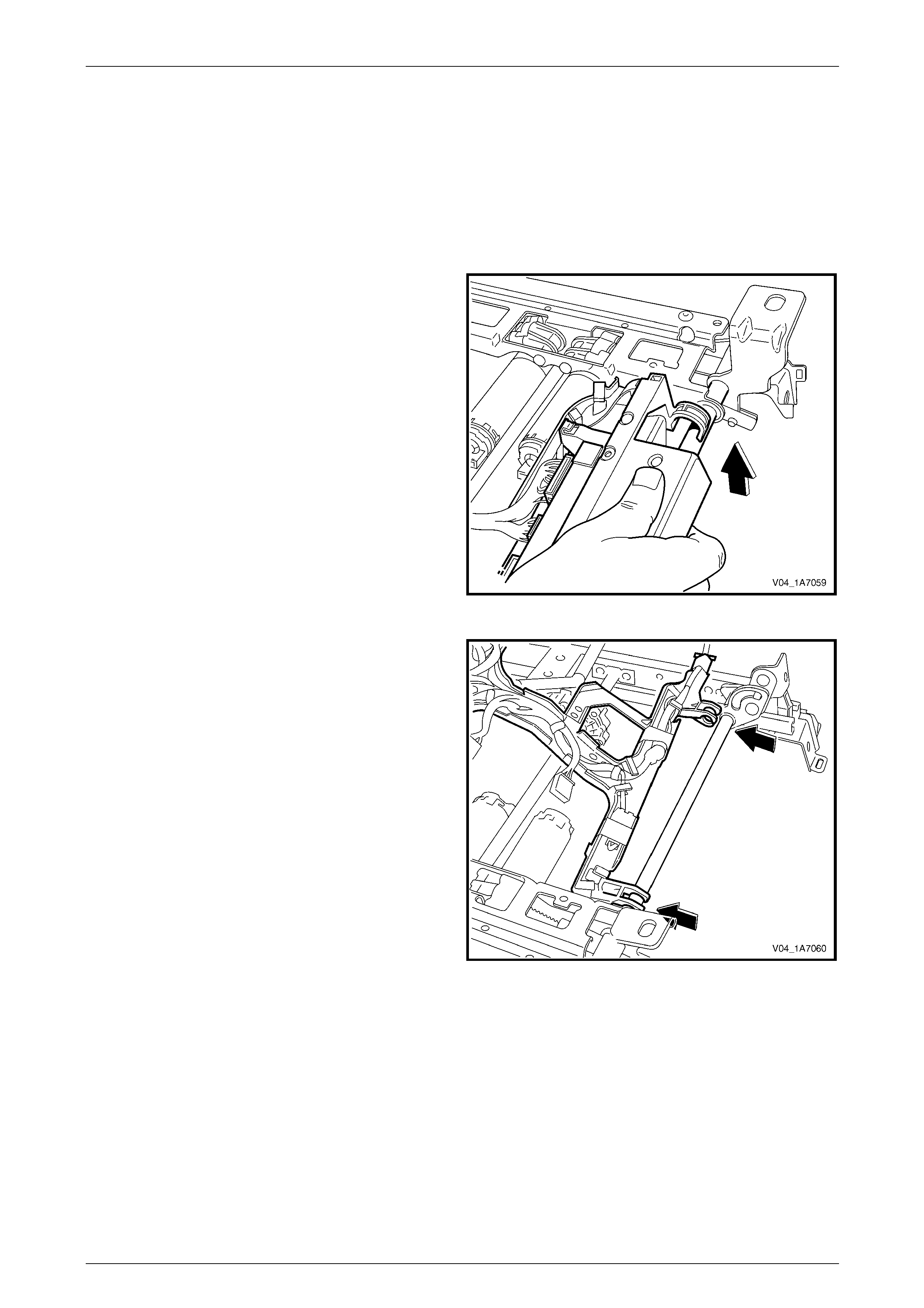
Seat Assemblies Page 1A7A–226
Page 1A7A–226
5.12 Seat Cable Tray and Memory Module
Remove
1 Remove the front seat assembly, refer to 5.3 Front Seat Assembly.
2 Remove the seat track and height adjust assembly, refer to 5.13 Track and Height Adjust Assembly.
3 Disconnect the wiring harness connectors as required.
4 Unclip the cable tray from the front of the seat track
and height adjust assembly.
Figure 1A7A – 98
5 Pull the cable tray forward to release it from the seat
track and height adjust assembly.
Figure 1A7A – 99
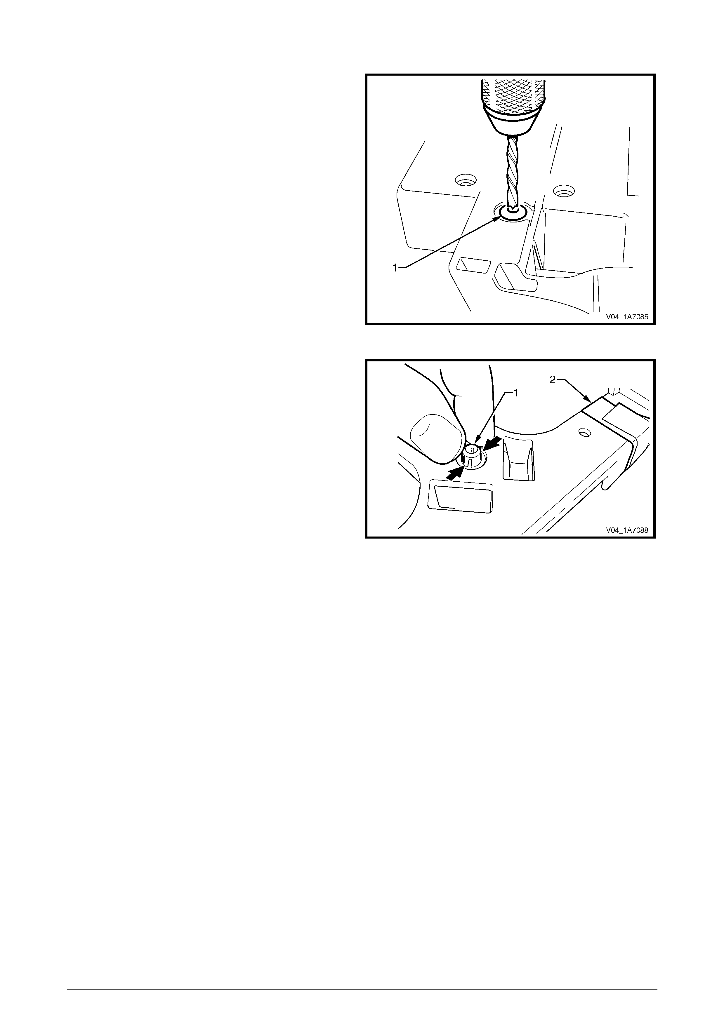
Seat Assemblies Page 1A7A–227
Page 1A7A–227
6 If required, use a 5 mm drill bit and dri ll out the pop
rivet (1), two places, securing the seat memor y
module to the cable tray.
7 Remove the seat memory module.
Figure 1A7A – 100
8 If required, remove the wiring harness from the cable
tray by squeezing the tabs on the harness clips (1)
and by removing the tape (2).
Figure 1A7A – 101
Reinstall
Reinstallation of the seat memor y module is the reverse of the removal procedure, noting the following:
1 Ensure the wiring harness an d connectors are correctly routed and attached securely.
2 Use new pop rivets.
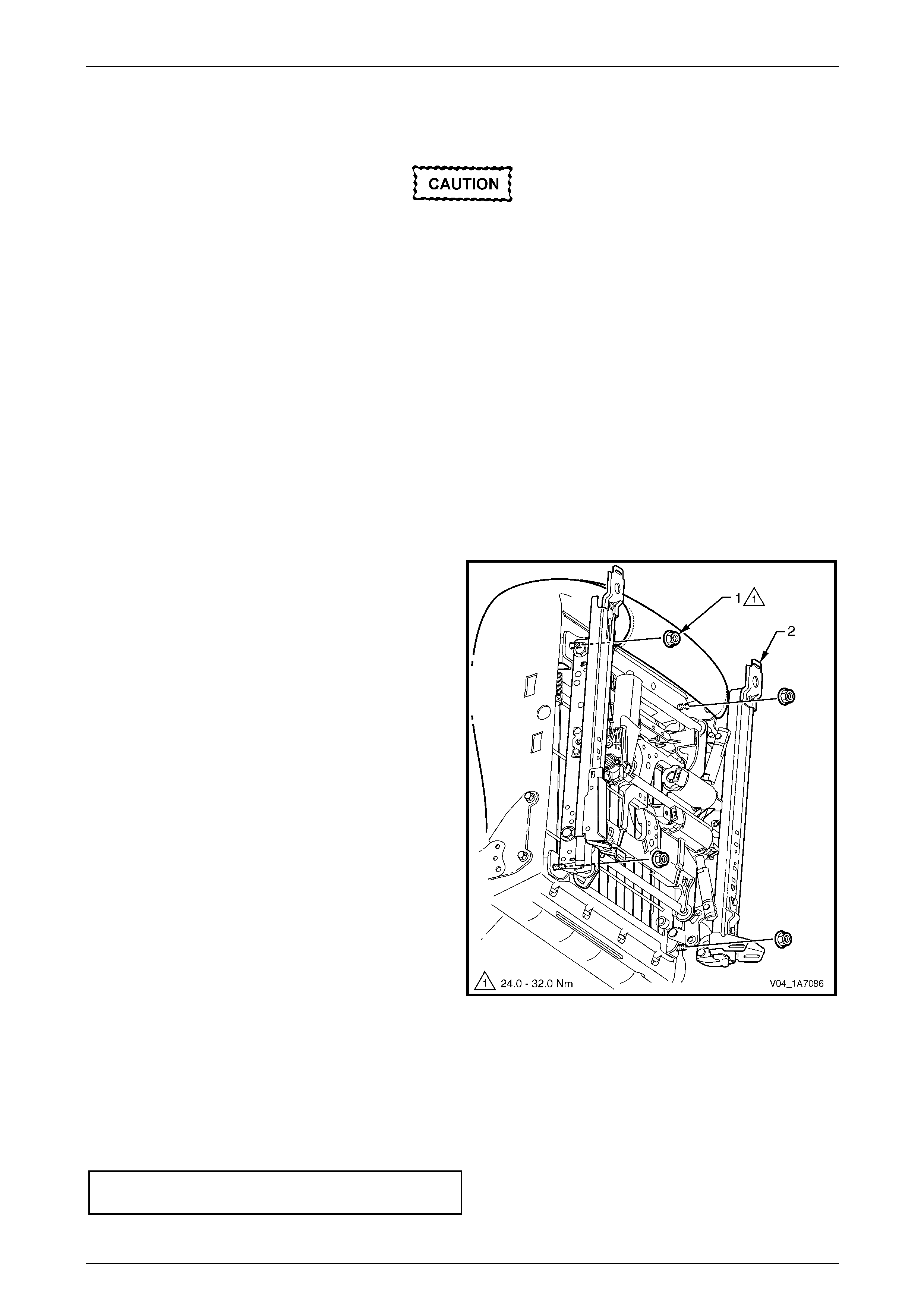
Seat Assemblies Page 1A7A–228
Page 1A7A–228
5.13 Track and Height Adjust Assembly
The track and height adjust assembly
components are non-serviceable. If the track
and height adjust assembly, drive motors or
drive shafts require replacement, the entire
track and height adjust assembly must be
replaced.
LT Section No. – 14-275
As required, remove the following compo nents:
1 Front seat assembly, refer to 5.3 Front Seat Assembly.
2 Front seat outer side cover assembly, refer to 5.4 Front Seat Outer Side Cover Assembly.
Remove
1 As required, detach the wiring harness con nectors.
2 As required, detach the seatbelt pretensioner and side airbag wiring harnesses.
3 Remove the four nuts (1) attaching the track and
height adjust assembly (2) to the seat.
4 Remove the track and height adjust assembly.
5 If required, remove the cable tray and
wiring harness assembly, refer to
5.12 Seat Cable Tray and Memory Module.
6 If required, remove the seatbelt buckle
and pretensioner assembl y, refer to
Section 12M Occupant Protection System.
Figure 1A7A – 102
Reinstall
Reinstallation of the track and height adjust assembly is the reverse of the removal procedur e, noting the following:
1 Ensure the connectors are correctly routed and attached securely.
2 Tighten the attaching nuts to the correct torque spec ification.
Track and height adjust asse mbly
attaching nut torque specification............24.0 – 32.0 Nm
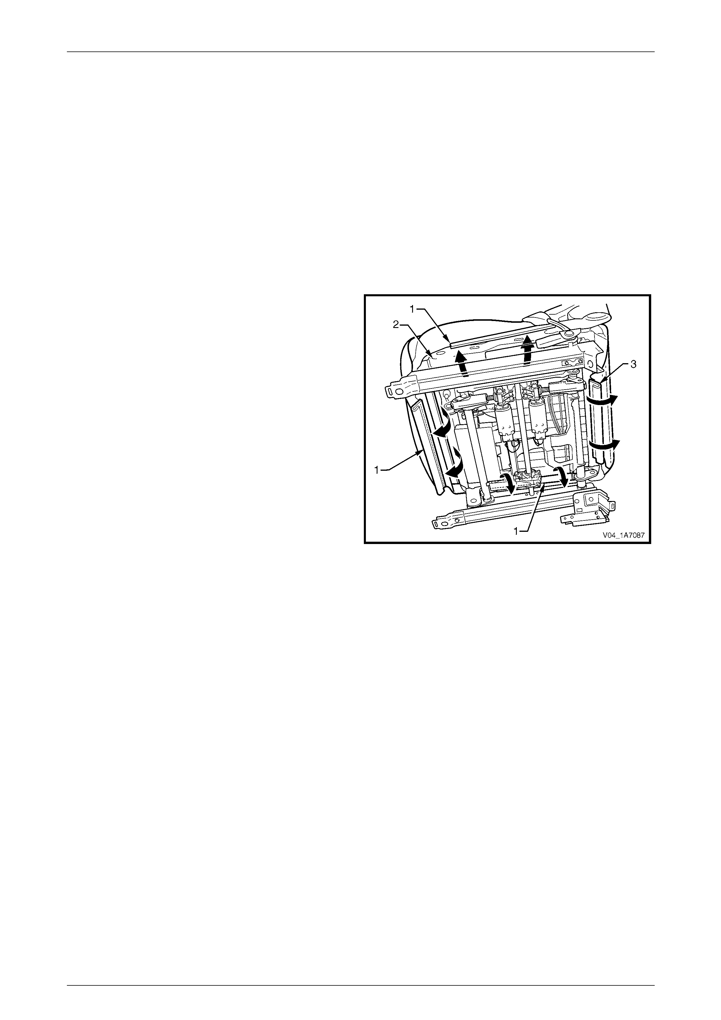
Seat Assemblies Page 1A7A–229
Page 1A7A–229
5.14 Front Seat Cushion Pad and Cover
Assembly
LT Section No. – 14-295
As required, remove the following compo nents:
1 Front seat assembly, refer to 5.3 Front Seat Assembly.
2 Front seat outer side cover assembly, refer to 5.4 Front Seat Outer Side Cover Assembly.
3 Front seat inner side cover, refer to 5.5 Front Seat Inner Side Cover.
4 Front seat-back frame assembly, refer to 5.11 Front Seat-back Frame Assembly.
Remove
1 From under the front seat cushion, disengage the front
and side J-strips (1) away from the seat frame (2).
2 Lift the cover and pad assembly a way from the seat
frame and then release the rear J-strip (3).
3 Remove the cover and pad assembly.
Figure 1A7A – 103
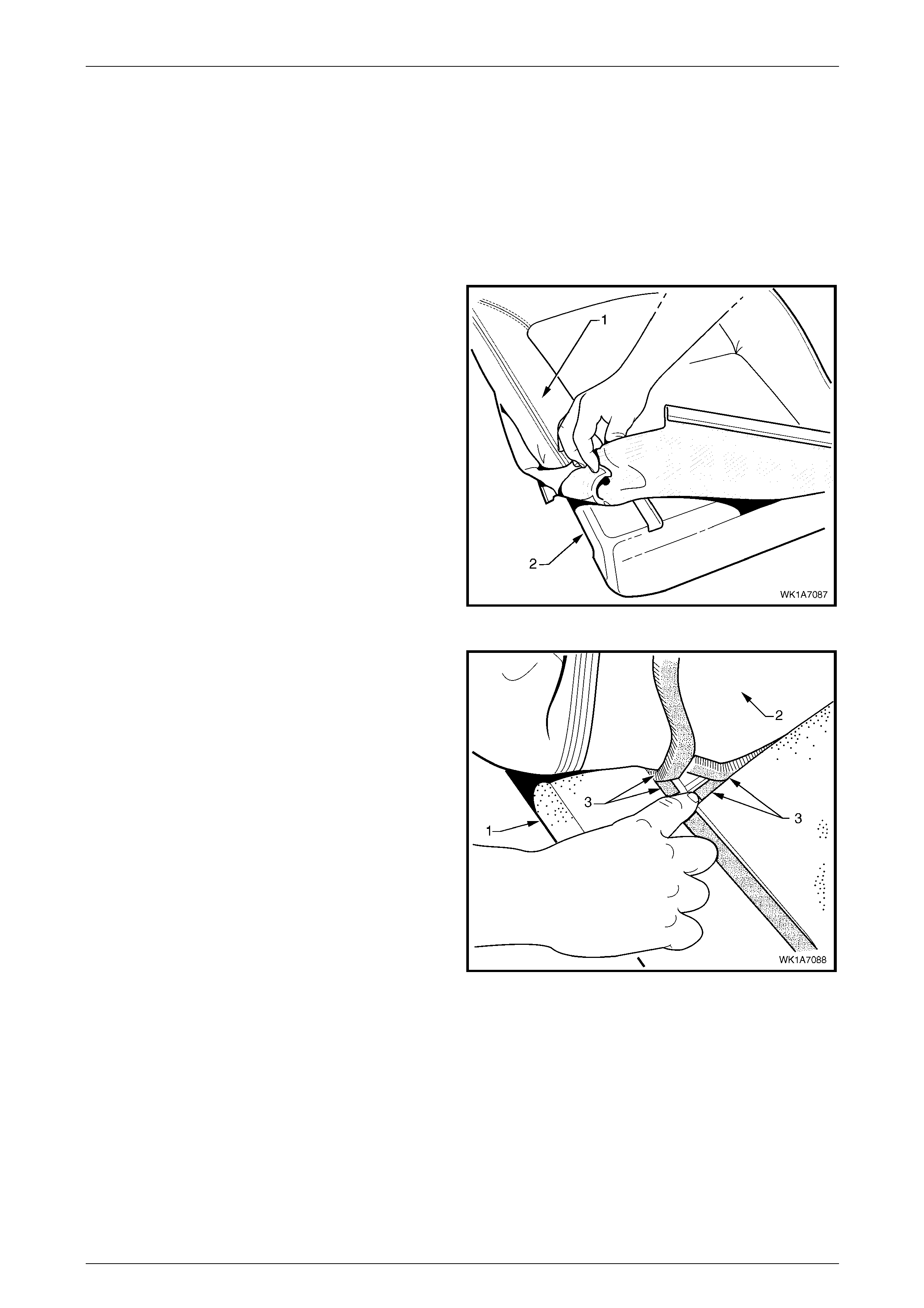
Seat Assemblies Page 1A7A–230
Page 1A7A–230
Disassemble
NOTE
The following illustrations show typical hook and
loop arrangement, which will vary according to
seat type.
Surebond type seat-back cover and pad
assemblies cannot be disassembled.
1 Fold the rear corners of the front seat cushion cover
(1) over the seat cushion pad (2).
Figure 1A7A – 104
2 While holding the front seat cushi on pad (1), pull the
rear corners of the seat cushion cover (2) forward and
away from the pad to disengage the hook and loop
strips (3).
3 Pull the cover up and over the forward edge of the
pad.
Figure 1A7A – 105
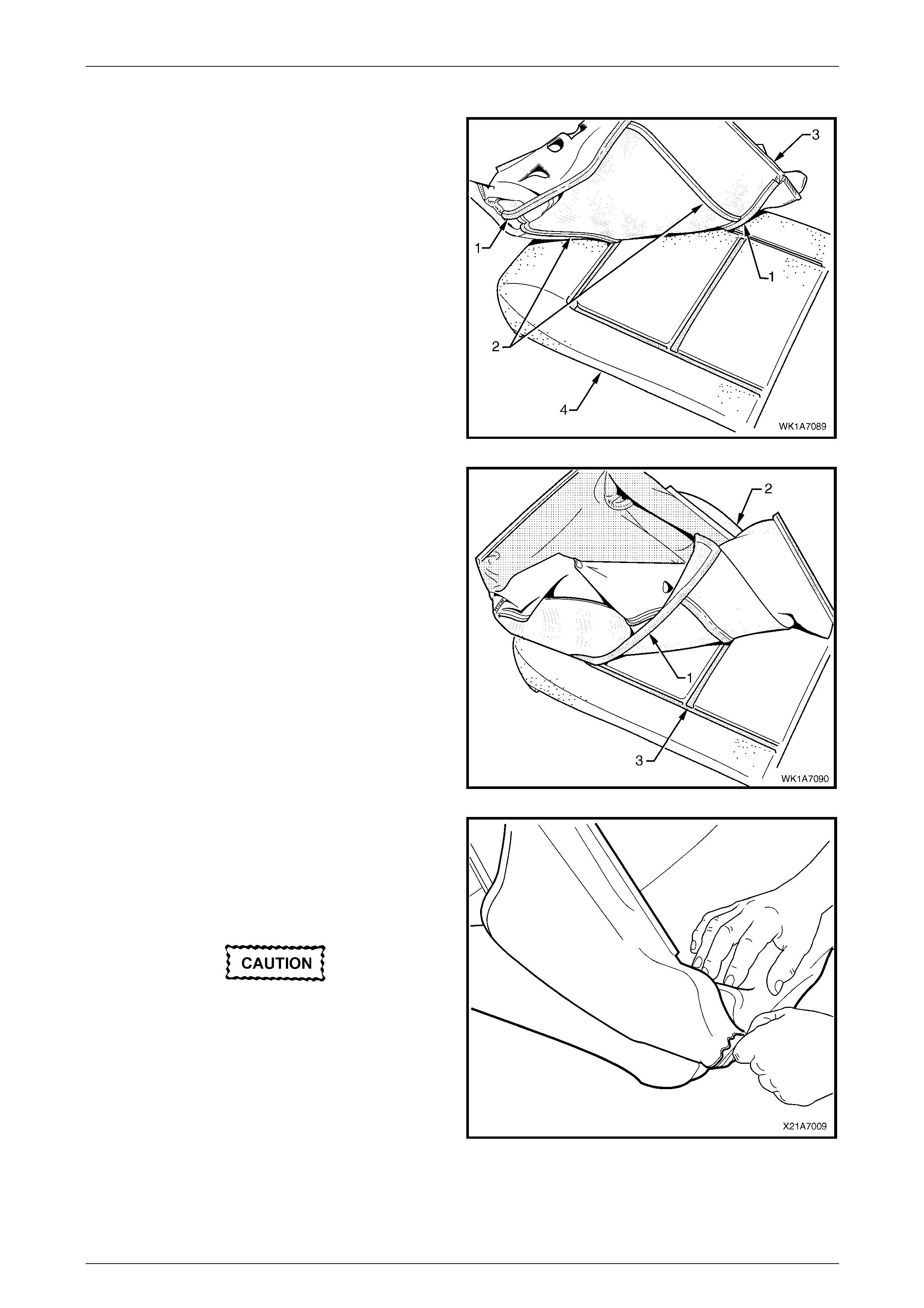
Seat Assemblies Page 1A7A–231
Page 1A7A–231
Reassemble
1 Align either of the outer hook and l oo p strips (1) and
the one or two cross hook and loop strips (2), on the
seat cushion cover (3), with the seat cushion pad (4).
2 Press the folded edge of the rear seat cushion cover
firmly into the corresponding groove in the seat
cushion pad to engage the hook and loop strip.
Figure 1A7A – 106
3 Align and press the outer hook and loop strip (1), on
the cover (2), with the corresponding groove in the p ad
(3).
Figure 1A7A – 107
4 Roll the front corners of the cover over the pad.
5 Roll the sides of the cover over the pad.
6 Roll the rear corners of the cover over the pad.
NOTE
Make sure the pad is fitted neatly by hand into all
corners and contours of the seat cover.
Do not pull the cover onto the pad from
underneath using the J-strip to make it fit
neatly, as the fabric may be damaged.
Figure 1A7A – 108
Reinstall
Reinstallation of the front seat cushion pad and cover assembly is the reverse of the removal procedure.
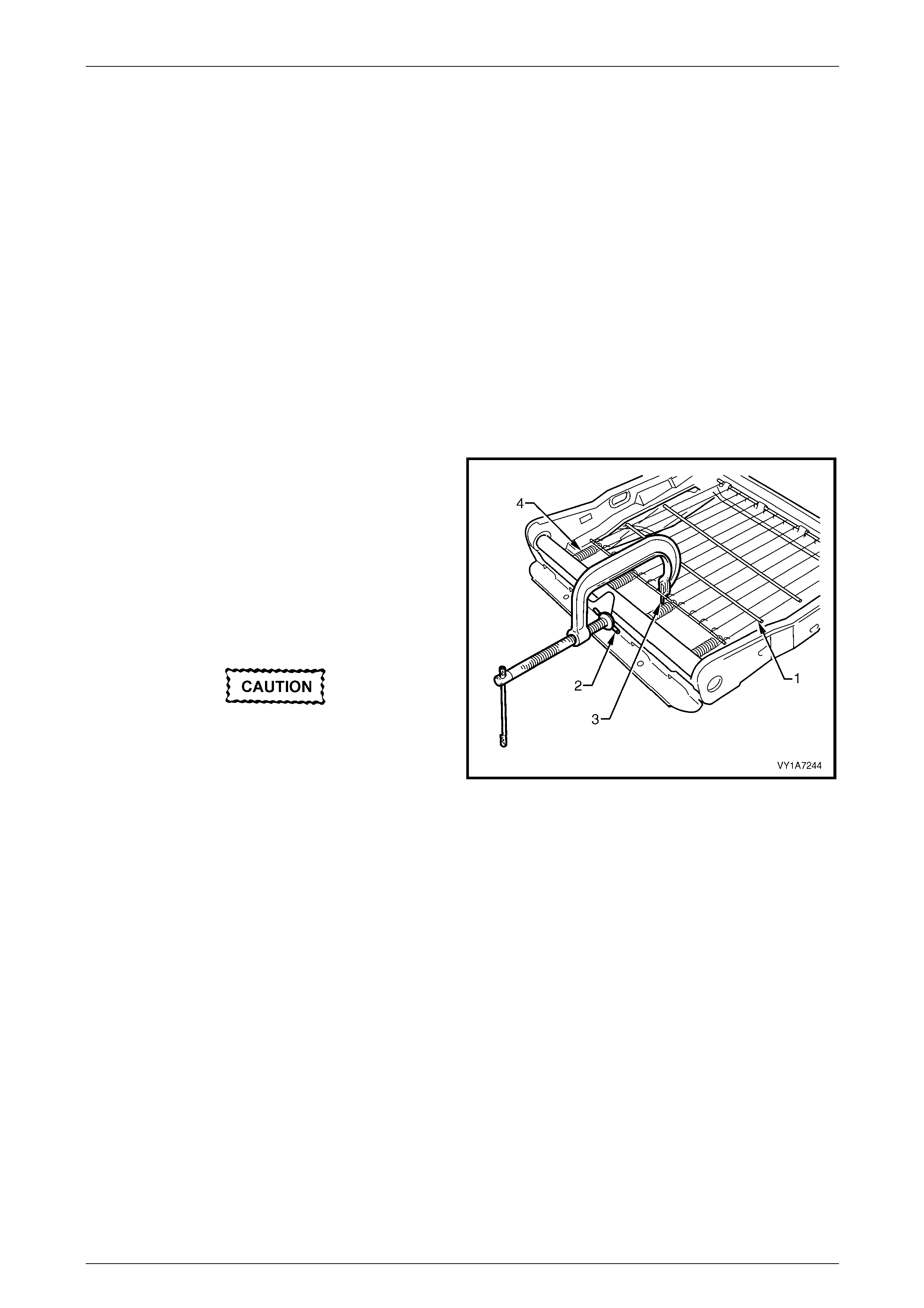
Seat Assemblies Page 1A7A–232
Page 1A7A–232
5.15 Front Seat Cushion Frame Assembly
LT Section No. – 14-275
Remove
As required, remove the following compo nents:
1 Front seat assembly, refer to 5.3 Front Seat Assembly.
2 Front seat outer side cover assembly, refer to 5.4 Front Seat Outer Side Cover Assembly.
3 Front seat inner side cover, refer to 5.5 Front Seat Inner Side Cover.
4 Front seat-back frame assembly, refer to 5.11 Front Seat-back Frame Assembly.
5 Track and height adjust assembly, refer to 5.13 Track and Height Adjust Assembly.
6 Front seat cushion pad and cover assembly, refer to 5.14 Front Seat Cushion Pad and Cover Assembly.
Disassemble
1 To remove the suspension mat (1), modify a G-clamp
with a 5 mm diameter metal dowel (2) welded to one
end and another appro ximately 40 mm long and with a
2 mm diameter pin (3) approximately 20 mm l ong
welded to the other end.
2 Using the G-clamp, stretch the suspension mat far
enough to allow for the retaining springs (4) to be
removed from the seat cushion frame.
3 Back the G-clamp load off and remove the suspensio n
mat.
When using the G-clamp, use existing holes
in the suspension mat to ensure mat
deformation does not occur.
Figure 1A7A – 109
Reassemble
Reassembly of the suspension mat is the reverse of the disassembl y proc edure.
Reinstall
Reinstallation of the front seat cushion frame assembly is the reverse of the removal proc edure, noting the following:
1 Ensure all wiring is correctly connected and routed, refer to Section 12O, Fuses, Relays and Wiring Harnesses.
2 Check the mechanical and ele c trical operation of the front seat.

Seat Assemblies Page 1A7A–233
Page 1A7A–233
5.16 Front Seat Lift Motor Assemblies
The front seat lift motor assemblies are non-serviceabl e items.
If a front seat lift motor assembly requires replacement, the track and height adjust assembly must be replaced,
refer to 5.13 Track and Height Adjust Assembly.

Seat Assemblies Page 1A7A–234
Page 1A7A–234
5.17 Front Seat Fore/Aft Movement Motor
Assembly
The front seat fore/aft movement motor assembl y is a non-serviceable item.
If the front seat fore/aft movement motor or drive shafts require replacement, the track and height adjus t assembly must
be replaced, refer to 5.13 Track and Height Adjust Assembly.

Seat Assemblies Page 1A7A–235
Page 1A7A–235
5.18 Front Seat-back Recline Motor Assembly
The front seat-back recline motor assembly is a non-serviceable item.
If the front seat-back recline motor assembly requires replacement, the fron t seat-back frame assembly must be
replaced, refer to 5.11 Front Seat-back Frame Assembly.

Seat Assemblies Page 1A7A–236
Page 1A7A–236
5.19 Drive Motor Hall-effect Sensors
The front seat drive motor hall-effect sensors are non-serviceable items.
If the front seat fore/aft movement and/or front seat lift motor hall-effect sensors require replacement, the track and
height adjust assembly must be replaced, refer to 5.13 Track and Heig ht Adjust Assembly.
If the seat-back recline motor hall-effect sensor requires replacement, the front seat-back frame assem bl y must be
replaced, refer to 5.11 Front Seat-back Frame Assembly.

Seat Assemblies Page 1A7A–237
Page 1A7A–237
6 Service Operations – Rear Seat
6.1 Usage Chart
How To Use This Chart
The following usage chart is provided to help determine the rear seat type fitted to the vehicle. T his is important prior to
repairs being performed as the failed/damaged part may no t be serviced.
To determine the seat type fitted to the vehicle, obtain th e vehicle model and the seat fabric t ype. Establish if the vehicl e
has an armrest and/or headrest. Using the chart will lead to the elimination of all other seat combinations, allowing for the
identification of the type and t he construction of the seat. Refer to the Figure shown in the Rear Seat T ype column for a
component breakdown of the rear seat assembly.
1 Vehicle – Vehicle mod el identification.
2 Fabric – Cloth or Leather seat covers.
3 Armrest with Compartment. – If the rear seat-back assembly is fitted with an armrest which incorporates a
convenience compartment.
4 Head Restraint – If the rear seat-back is fitted with a headrest.
5 Centre Head Restraint – If the rear seat is fitted with a centre headrest.
6 Construction – Surebond refers to the seat cover being glued to the seat pad. This type is serviced as a cover and
pad assembly only. Hook an d Loop refers to the seat cover being attached to the seat pa d with a Velcro type
material and both being servi c ed as separate parts. Conventional Pull-down refers to the seat cover being attached
to the pad and frame with a retainer wire and hog rings, with all parts being serviced.
7 Rear Seat Type – Identifies the seat type and provides reference to illustrations which show a breakdown of the
serviced component for each rear seat assembly.
Domestic
Vehicle Fabric Armrest
(With
Compartment)
Head
Restraint Centre Head
Restraint Construction Rear Seat Type
(Refer to)
Statesman
– Level 4 Cloth Yes Yes Yes Conventional
Pull-down 1
(Figure 1A7A – 110)
Statesman
– Level 4 Leather Yes Yes Yes Conventional
Pull-down 2
(Figure 1A7A – 111)
Caprice
– Level 5
Two
Passenger
Rear Seat
Leather Yes Yes Yes Conventional
Pull-down 3
(Figure 1A7A – 112)
Caprice
– Level 5
Three
Passenger
Rear Seat
Leather Yes Yes Yes Conventional
Pull-down 4
(Figure 1A7A – 113)

Seat Assemblies Page 1A7A–238
Page 1A7A–238
Gulf States
Vehicle Fabric Armrest
(With
Compartment)
Head
Restraint Centre head
Restraint Construction Rear Seat Type
(Refer to)
Caprice
LS
– Level 1
Cloth No No No Surebond 5
(Figure 1A7A – 114)
Caprice
LTZ
– Level 2
Cloth No Yes No Conventional
Pull-down 6
(Figure 1A7A – 115)
Caprice
LTZ
– Level 2
Leather No Yes No Conventional
Pull-down 7
(Figure 1A7A – 116)
Caprice
SS
– Level 3
Leather No Yes Yes Hook and Loop 8
(Figure 1A7A – 117)
Caprice
Royale
– Level 5
Two
Passenger
Rear Seat
Leather Yes Yes Yes Conventional
Pull-down 3
(Figure 1A7A – 112)
Caprice
Royale
– Level 5
Three
Passenger
Rear Seat
Leather Yes Yes Yes Conventional
Pull-down 4
(Figure 1A7A – 113)
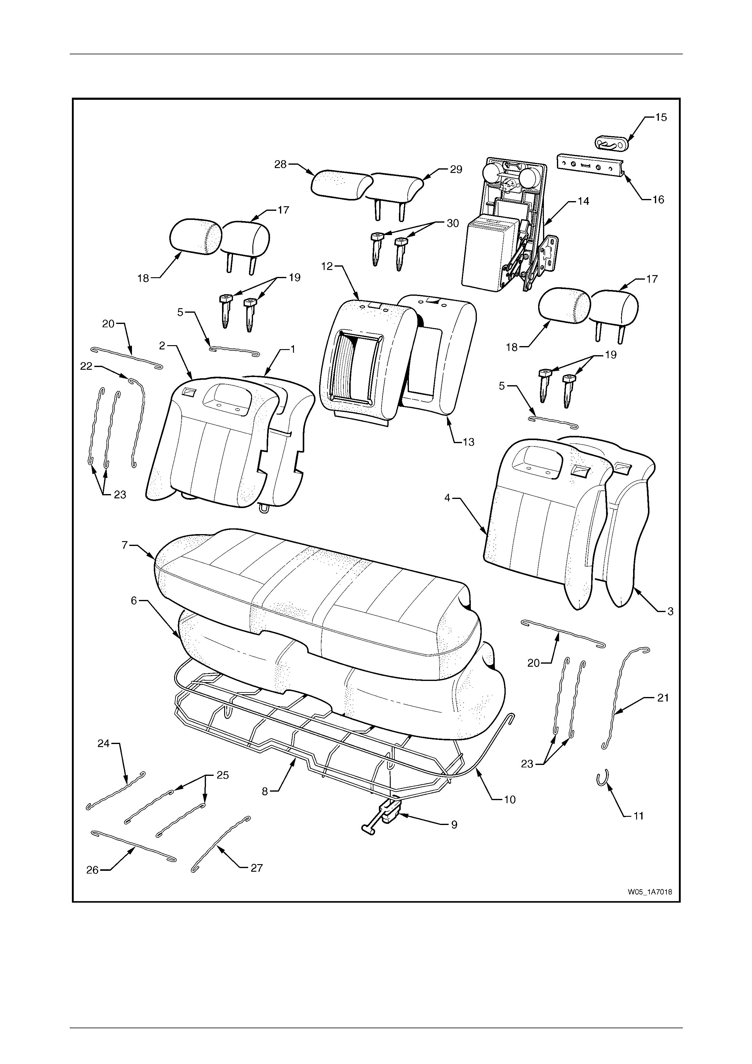
Seat Assemblies Page 1A7A–239
Page 1A7A–239
Rear Seat Type 1
Figure 1A7A – 110

Seat Assemblies Page 1A7A–240
Page 1A7A–240
Legend
1 Rear Seat-back Pad and Frame Assembly – Right-hand
2 Rear Seat-back Cover – Right-hand
3 Rear Seat-back Pad and Frame Assembly – Left-hand
4 Rear Seat-back Cover – Left-hand
5 Rear Seat-back Cover Retainer Wire
6 Rear Seat Cushion Pad
7 Rear Seat Cushion Cover
8 Rear Seat Cushion Frame
9 Rear Seat Cushion Release Handle (2 Places)
10 Rear Seat Cushion Cover Retainer Wire
11 Hog Ring
12 Rear Seat-back Centre Cover
13 Rear Seat-back Centre Pad
14 Rear Seat-back Centre Tray and Armrest Assembly ∗
15 Rear Seat-back Centre Lock Striker
16 Rear Seat-back Centre Striker Cover
17 Rear Seat-back Head Restraint Pad Assembly
18 Rear Seat-back Head Restraint Cover
19 Rear Seat-back Head Restraint Sleeves
20 Rear Seat-back Upper Horizontal Groove Retainer Wire
21 Rear Seat-back Outer Retainer Wire – Left-hand
22 Rear Seat-back Outer Retainer Wire – Right-hand
23 Rear Seat-back Vertical Groove Retainer Wire
24 Rear Seat Cushion Cover Outer Retainer Wire (2 Places)
25 Rear Seat Cushion Cover Centre Retainer Wire (4 Places)
26 Rear Seat Cushion Front Retainer Wire (2 Places)
27 Rear Seat Cushion Cover Inner Retainer Wire (2 Places)
28 Rear Seat-back Centre Head Restraint Cover
29 Rear Seat-back Centre Head Restraint Pad
30 Rear Seat-back Centre Head Restraint Sleeves
∗ Refer to Figure 1A7A – 119 for a breakdown of the rear seat-back centre tray and armrest assembly.
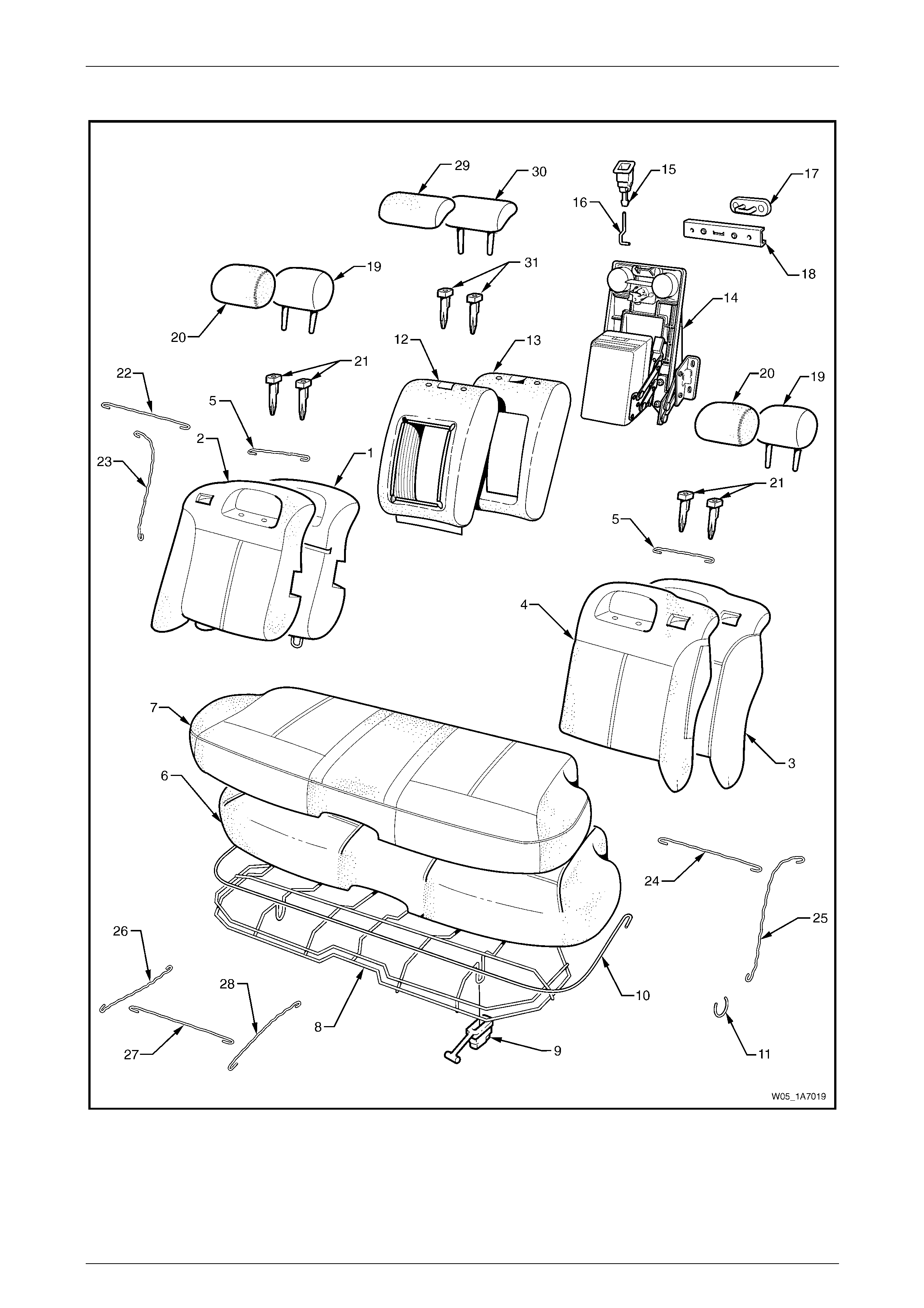
Seat Assemblies Page 1A7A–241
Page 1A7A–241
Rear Seat Type 2
Figure 1A7A – 111

Seat Assemblies Page 1A7A–242
Page 1A7A–242
Legend
1 Rear Seat-back Pad and Frame Assembly – Right-hand
2 Rear Seat-back Cover – Right-hand
3 Rear Seat-back Pad and Frame Assembly – Left-hand
4 Rear Seat-back Cover – Left-hand
5 Rear Seat-back Cover Retainer Wire
6 Rear Seat Cushion Pad
7 Rear Seat Cushion Cover
8 Rear Seat Cushion Frame
9 Rear Seat Cushion Release Handle (2 Places)
10 Rear Seat Cushion Cover Retainer Wire
11 Hog Ring
12 Rear Seat-back Centre Cover
13 Rear Seat-back Centre Pad
14 Rear Seat-back Centre Tray and Armrest Assembly ∗
15 Rear Seat-back Centre Release Button
16 Release Button Rod
17 Rear Seat-back Centre Lock Striker
18 Rear Seat-back Centre Striker Cover
19 Rear Seat-back Head Restraint Pad Assembly
20 Rear Seat-back Head Restraint Cover
21 Rear Seat-back Head Restraint Sleeves
22 Rear Seat-back Upper Horizontal Groove Retainer Wire
23 Rear Seat-back Outer Retainer Wire
24 Rear Seat-back Upper Horizontal Groove Retainer Wire
25 Rear Seat-back Outer Retainer Wire
26 Rear Seat Cushion Cover Outer Retainer Wire (2 Places)
27 Rear Seat Cushion Cover Front Retainer Wire (2 Places)
28 Rear Seat Cushion Cover Inner Retainer Wire (2 Places)
29 Rear Seat-back Centre Head Restraint Cover
30 Rear Seat-back Centre Head Restraint Pad
31 Rear Seat-back Centre Head Restraint Sleeves
∗ Refer to Figure 1A7A – 119 for a breakdown of the rear seat-back centre tray and armrest assembly.
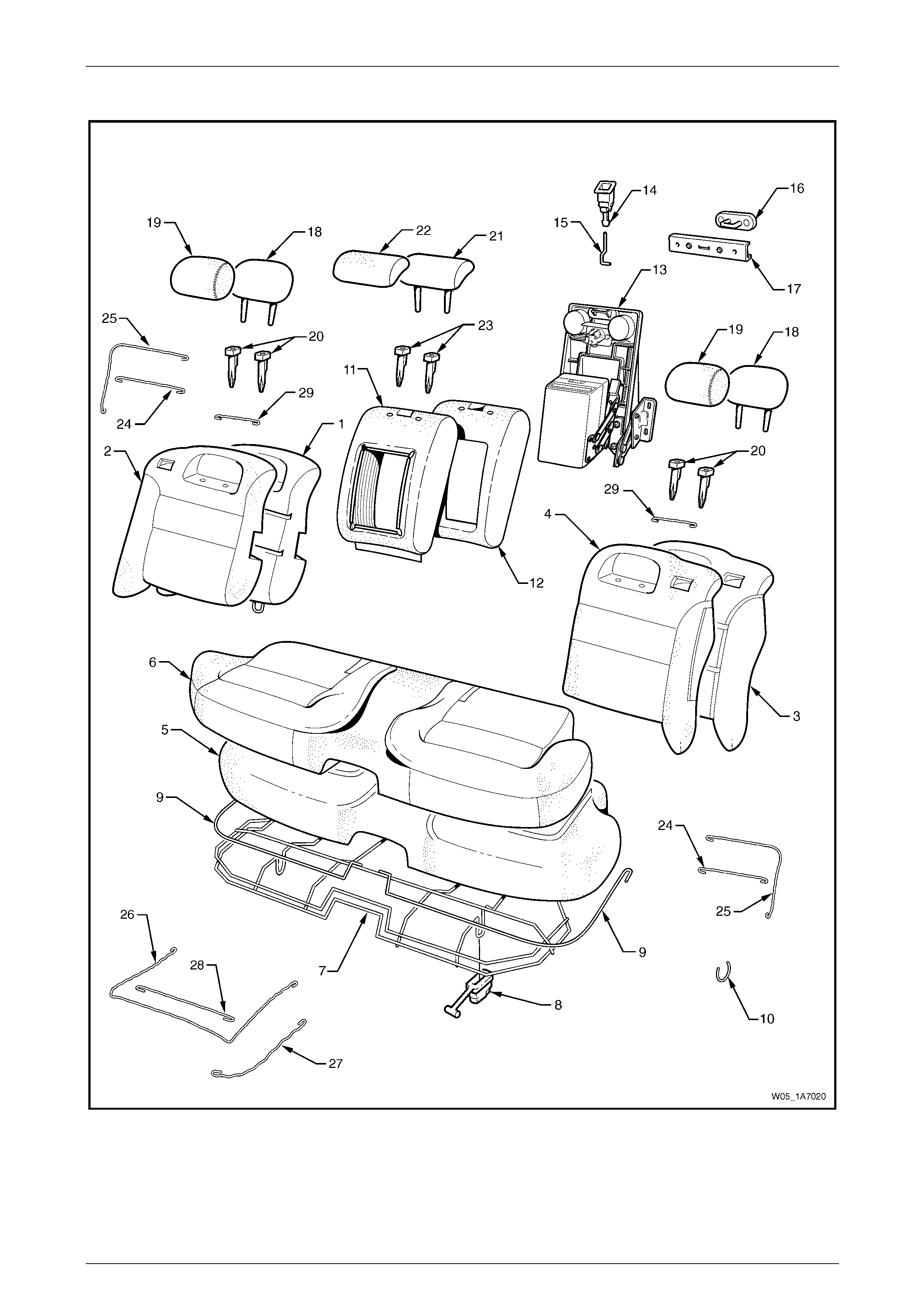
Seat Assemblies Page 1A7A–243
Page 1A7A–243
Rear Seat Type 3
Figure 1A7A – 112

Seat Assemblies Page 1A7A–244
Page 1A7A–244
Legend
1 Rear Seat-back Pad and Frame Assembly – Right-hand
2 Rear Seat-back Cover – Right-hand
3 Rear Seat-back Pad and Frame Assembly – Left-hand
4 Rear Seat-back Cover – Left-hand
5 Rear Seat Cushion Pad
6 Rear Seat Cushion Cover
7 Rear Seat Cushion Frame
8 Rear Seat Cushion Release Handle (2 Places)
9 Rear Seat Cushion Cover Retainer Wire
10 Hog Ring
11 Rear Seat-back Centre Cover
12 Rear Seat-back Centre Pad
13 Rear Seat-back Centre Tray and Armrest Assembly ∗
14 Rear Seat-back Centre Release Button
15 Release Button Rod
16 Rear Seat-back Centre Lock Striker
17 Rear Seat-back Centre Striker Cover
18 Rear Seat-back Head Restraint Pad Assembly
19 Rear Seat-back Head Restraint Cover
20 Rear Seat-back Head Restraint Sleeves
21 Rear Seat-back Centre Head Restraint Pad
22 Rear Seat-back Centre Head Restraint Cover
23 Centre Head Restraint Sleeves
24 Rear Seat-back Inner Horizontal Groove Retainer Wire
25 Rear Seat-back Outer Groove Retainer Wire
26 Rear Seat Cushion Cover Outer Retainer Wire (2 Places)
27 Rear Seat Cushion Cover Inner Retainer Wire (2 Places)
28 Rear Seat Cushion Cover Front Retainer Wire (2 Places)
29 Rear Seat-back Cushion Head Restraint Retainer Wire
∗ Refer to Figure 1A7A – 119 for a breakdown of the rear seat-back centre tray and armrest assembly.
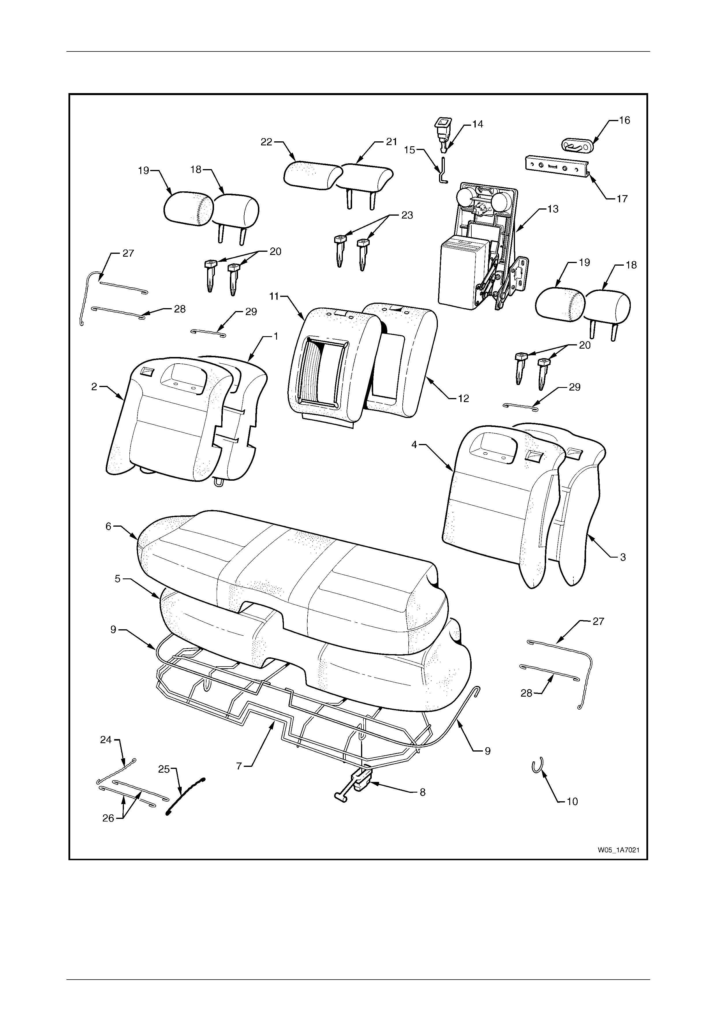
Seat Assemblies Page 1A7A–245
Page 1A7A–245
Rear Seat Type 4
Figure 1A7A – 113

Seat Assemblies Page 1A7A–246
Page 1A7A–246
Legend
1 Rear Seat-back Pad and Frame Assembly – Right-hand
2 Rear Seat-back Cover – Right-hand
3 Rear Seat-back Pad and Frame Assembly – Left-hand
4 Rear Seat-back Cover – Left-hand
5 Rear Seat Cushion Pad
6 Rear Seat Cushion Cover
7 Rear Seat Cushion Frame
8 Rear Seat Cushion Release Handle (2 Places)
9 Rear Seat Cushion Cover Retainer Wire
10 Hog Ring
11 Rear Seat-back Centre Cover
12 Rear Seat-back Centre Pad
13 Rear Seat-back Centre Tray and Armrest Assembly ∗
14 Rear Seat-back Centre Release Button
15 Release Button Rod
16 Rear Seat-back Centre Lock Striker
17 Rear Seat-back Centre Striker Cover
18 Rear Seat-back Head Restraint Pad Assembly
19 Rear Seat-back Head Restraint Cover
20 Rear Seat-back Head Restraint Sleeves
21 Rear Seat-back Centre Head Restraint Pad Assembly
22 Rear Seat-back Centre Head Restraint Cover
23 Rear Seat-back Centre Head Restraint Sleeves
24 Rear Seat Cushion Cover Outer Retainer Wire (2 Places)
25 Rear Seat Cushion Cover Inner Retainer Wire (2 Places)
26 Rear Seat Cushion Cover Front Retainer Wire (4 Places)
27 Rear Seat-back Outer Groove Retainer Wire
28 Rear Seat-back Cushion Inner Horizontal Groove Retainer
Wire
29 Rear Seat-back Cushion Head Restraint Retainer Wire
* Refer to Figure 1A7A – 119 for a breakdo wn of the rear seat-back centre tray and armrest assembly.
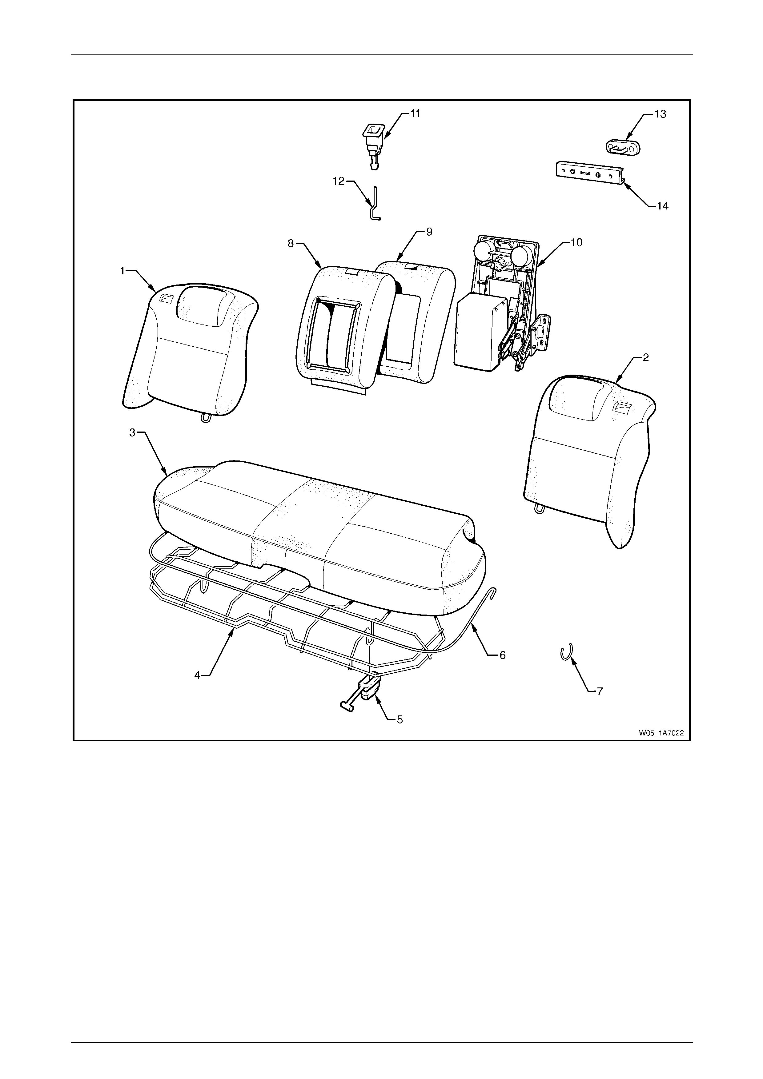
Seat Assemblies Page 1A7A–247
Page 1A7A–247
Rear Seat Type 5
Figure 1A7A – 114
Legend
1 Rear Seat-back Assembly – Right-hand
2 Rear Seat-back Assembly – Left-hand
3 Rear Seat Cushion Cover and Pad Assembly
4 Rear Seat Cushion Frame
5 Rear Seat Cushion Release Handle (2 Places)
6 Rear Seat Cushion Cover Wire Retainer
7 Hog Ring
8 Rear Seat-back Centre Cover
9 Rear Seat-back Centre Pad
10 Rear Seat-back Centre Tray and Armrest Assembly ∗
11 Rear Seat-back Centre Release Button
12 Release Button Rod
13 Rear Seat-back Centre Lock Striker
14 Rear Seat-back Centre Striker Cover
* Refer to Figure 1A7A – 118 for a breakdo wn of the rear seat-back centre armrest assembly.
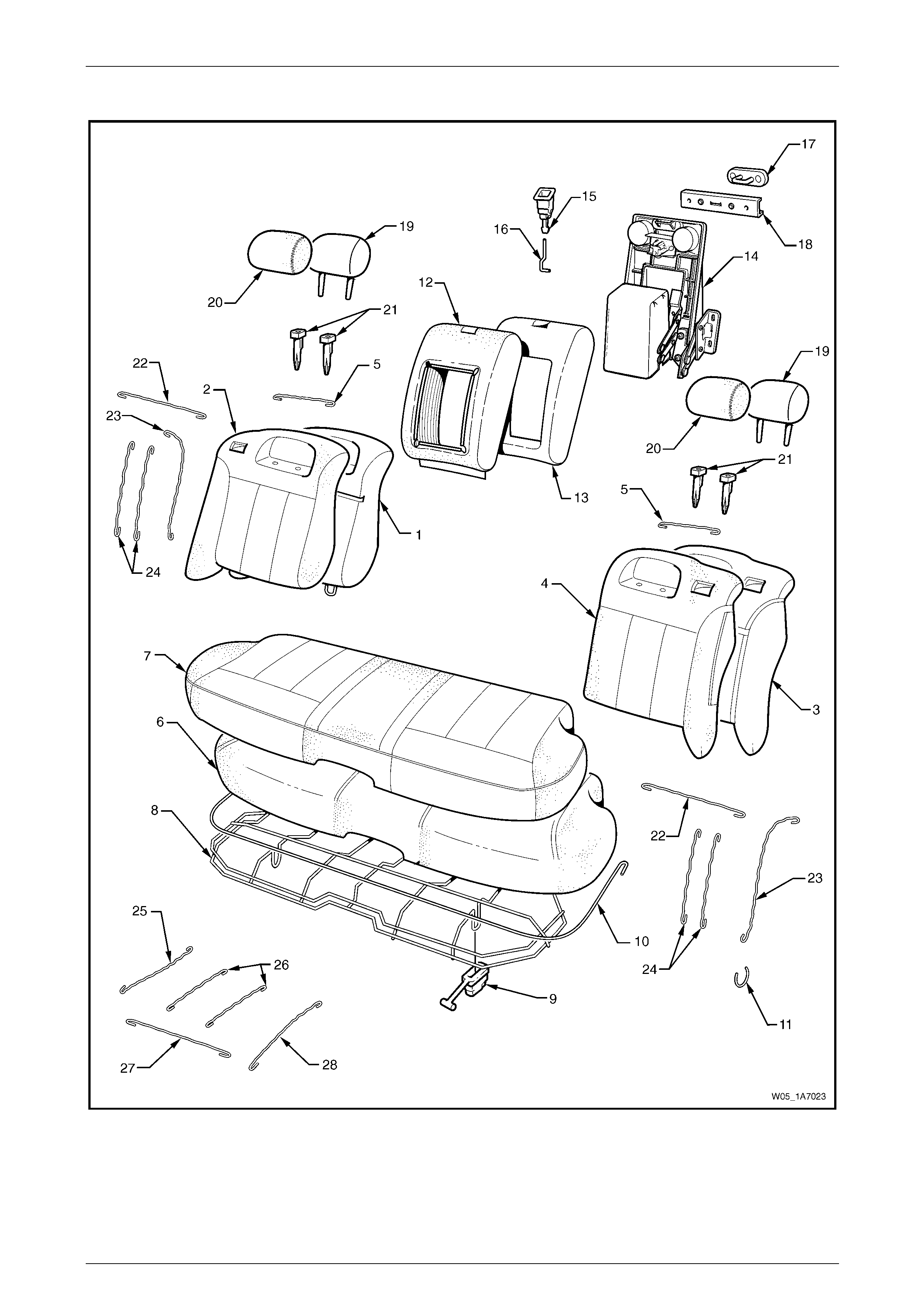
Seat Assemblies Page 1A7A–248
Page 1A7A–248
Rear Seat Type 6
Figure 1A7A – 115

Seat Assemblies Page 1A7A–249
Page 1A7A–249
Legend
1 Rear Seat-back Pad and Frame Assembly – Right-hand
2 Rear Seat-back Cover Assembly – Right-hand
3 Rear Seat-back Pad and Frame Assembly – Left-hand
4 Rear Seat-back Cover Assembly – Left-hand
5 Rear Seat-back Cover Retainer Wire
6 Rear Seat Cushion Pad
7 Rear Seat Cushion Cover
8 Rear Seat Cushion Frame
9 Rear Seat Cushion Release Handle (2 Places)
10 Rear Seat Cushion Cover Retainer Wire
11 Hog Ring
12 Rear Seat-back Centre Cover
13 Rear Seat-back Centre Pad
14 Rear Seat-back Centre Tray and Armrest Assembly ∗
15 Rear Seat-back Centre Release Button
16 Release Button Rod
17 Rear Seat-back Centre Lock Striker
18 Rear Seat-back Centre Striker Cover
19 Rear Seat-back Head Restraint Pad Assembly
20 Head Restraint Cover
21 Head Restraint Sleeves
22 Rear Seat-back Upper Horizontal Groove Retainer Wire
23 Rear Seat-back Outer Groove Retainer Wire
24 Rear Seat-back Upper Horizontal Groove Retainer Wires
25 Rear Seat Cushion Cover Outer Retainer Wire (2 Places)
26 Rear Seat Cushion Cover Centre Retainer Wire (4 Places)
27 Rear Seat Cushion Cover Front Retainer Wire (2 Places)
28 Rear Seat Cushion Inner Retaining Wire (2 Places)
* Refer to Figure 1A7A – 118 for a breakdown of the rear seat-back centre armrest assembly.
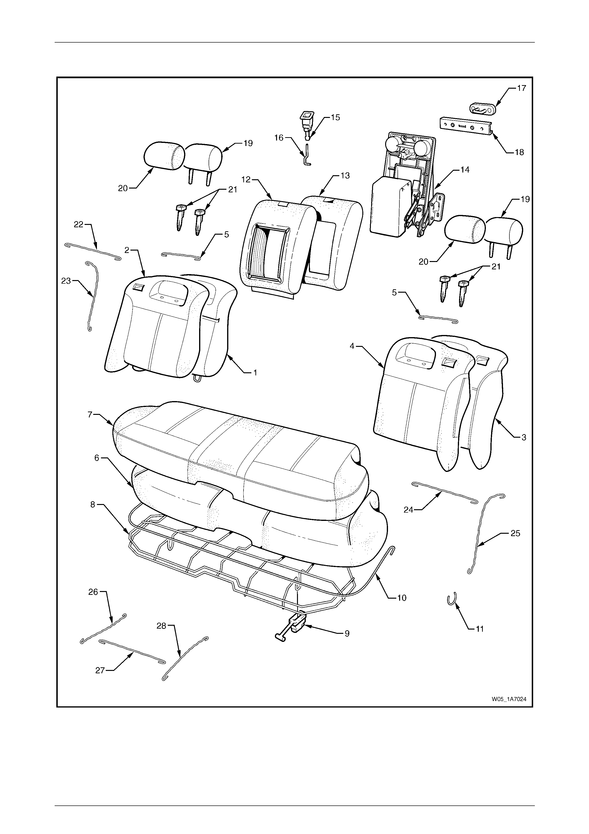
Seat Assemblies Page 1A7A–250
Page 1A7A–250
Rear Seat Type 7
Figure 1A7A – 116

Seat Assemblies Page 1A7A–251
Page 1A7A–251
Legend
1 Rear Seat-back Pad and Frame Assembly – Right-hand
2 Rear Seat-back Cover – Right-hand
3 Rear Seat-back Pad and Frame Assembly – Left-hand
4 Rear Seat-back Cover – Left-hand
5 Rear Seat-back Cover Retainer Wire
6 Rear Seat Cushion Pad
7 Rear Seat Cushion Cover
8 Rear Seat Cushion Frame
9 Rear Seat Cushion Release Handle (2 Places)
10 Rear Seat Cushion Cover Retainer Wire
11 Hog Ring
12 Rear Seat-back Centre Cover
13 Rear Seat-back Centre Pad
14 Rear Seat-back Centre Tray and Armrest Assembly ∗
15 Rear Seat-back Centre Release Button
16 Release Button Rod
17 Rear Seat-back Centre Lock Striker
18 Rear Seat-back Centre Striker Cover
19 Rear Seat-back Head Restraint Pad Assembly
20 Head Restraint Cover
21 Head Restraint Sleeves
22 Rear Seat-back Upper Horizontal Groove Retainer Wire –
Right-hand
23 Rear Seat-back Outer Retainer Wire – Right-hand
24 Rear Seat-back Upper Horizontal Groove Retainer Wire –
Left-hand
25 Rear Seat-back Outer Retainer Wire – Left-hand
26 Rear Seat Cushion Cover Outer Retainer Wire (2 Places)
27 Rear Seat Cushion Cover Front Retainer Wire (2 Places)
28 Rear Seat Cushion Inner Retaining Wire (2 Places)
∗ Refer to Figure 1A7A – 118 for a breakdown of the rear seat-back centre armrest assembly.
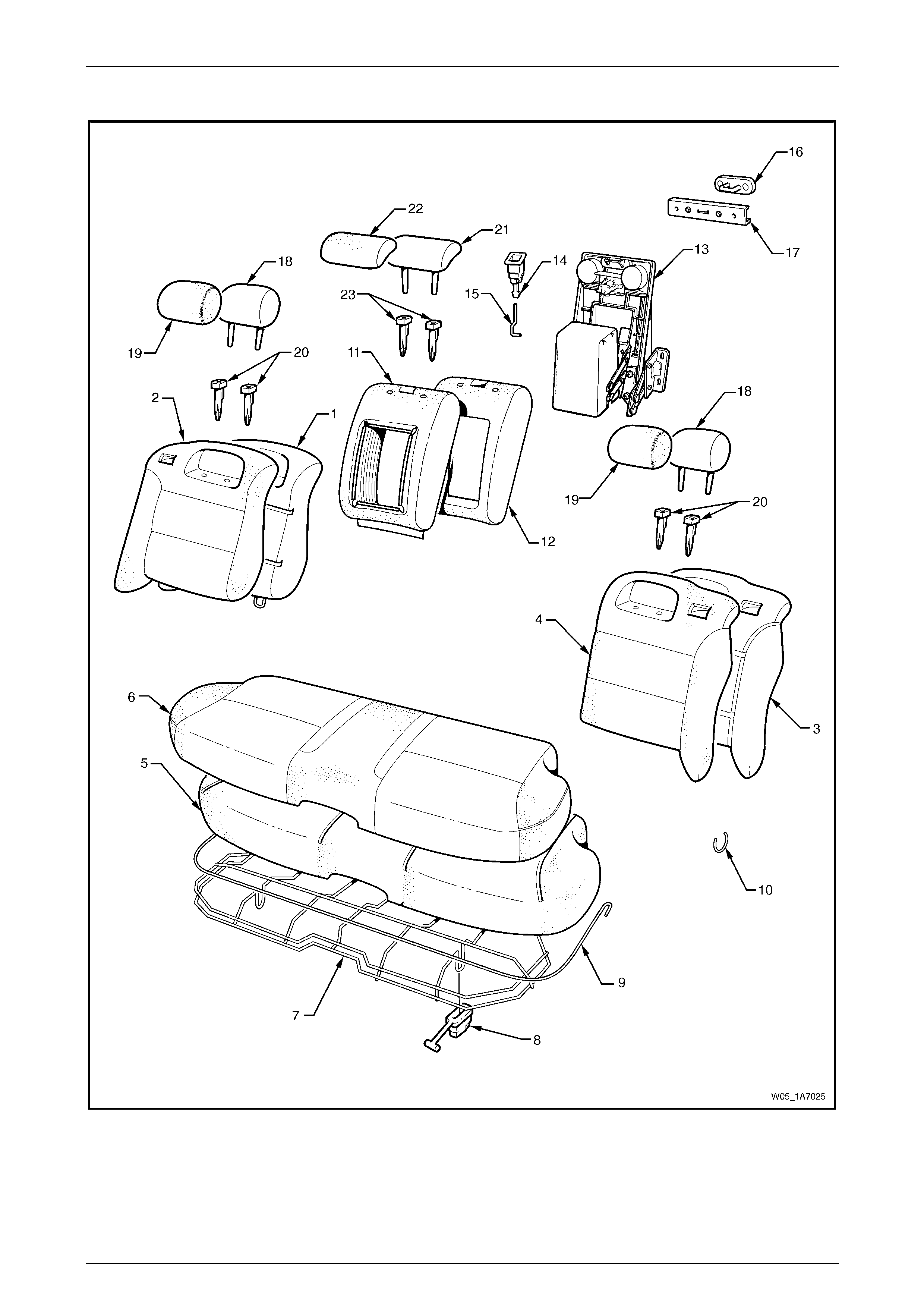
Seat Assemblies Page 1A7A–252
Page 1A7A–252
Rear Seat Type 8
Figure 1A7A – 117

Seat Assemblies Page 1A7A–253
Page 1A7A–253
Legend
1 Rear Seat-back Pad and Frame Assembly – Right-hand
2 Rear Seat-back Cover – Right-hand
3 Rear Seat-back Pad and Frame Assembly – Left-hand
4 Rear Seat-back Cover – Left-hand
5 Rear Seat Cushion Pad
6 Rear Seat Cushion Cover
7 Rear Seat Cushion Frame
8 Rear Seat Cushion Release Handle (2 Places)
9 Rear Seat Cushion Cover Retainer Wire
10 Hog Ring
11 Rear Seat-back Centre Cover
12 Rear Seat-back Centre Pad
13 Rear Seat-back Centre Tray and Armrest Assembly ∗
14 Rear Seat-back Centre Release Button
15 Release Button Rod
16 Rear Seat-back Centre Lock Striker
17 Rear Seat-back Centre Striker Cover
18 Rear Seat-back Head Restraint Pad Assembly
19 Rear Seat-back Head Restraint Cover
20 Rear Seat-back Head Restraint Sleeves
21 Rear Seat-back Head Centre Head Restraint Pad Assembly
22 Rear Seat-back Head Centre Head Restraint Cover
23 Rear Seat-back Head Centre Head Restraint Sleeves
* Refer to Figure 1A7A – 118 for a breakdo wn of the rear seat-back centre armrest assembly.
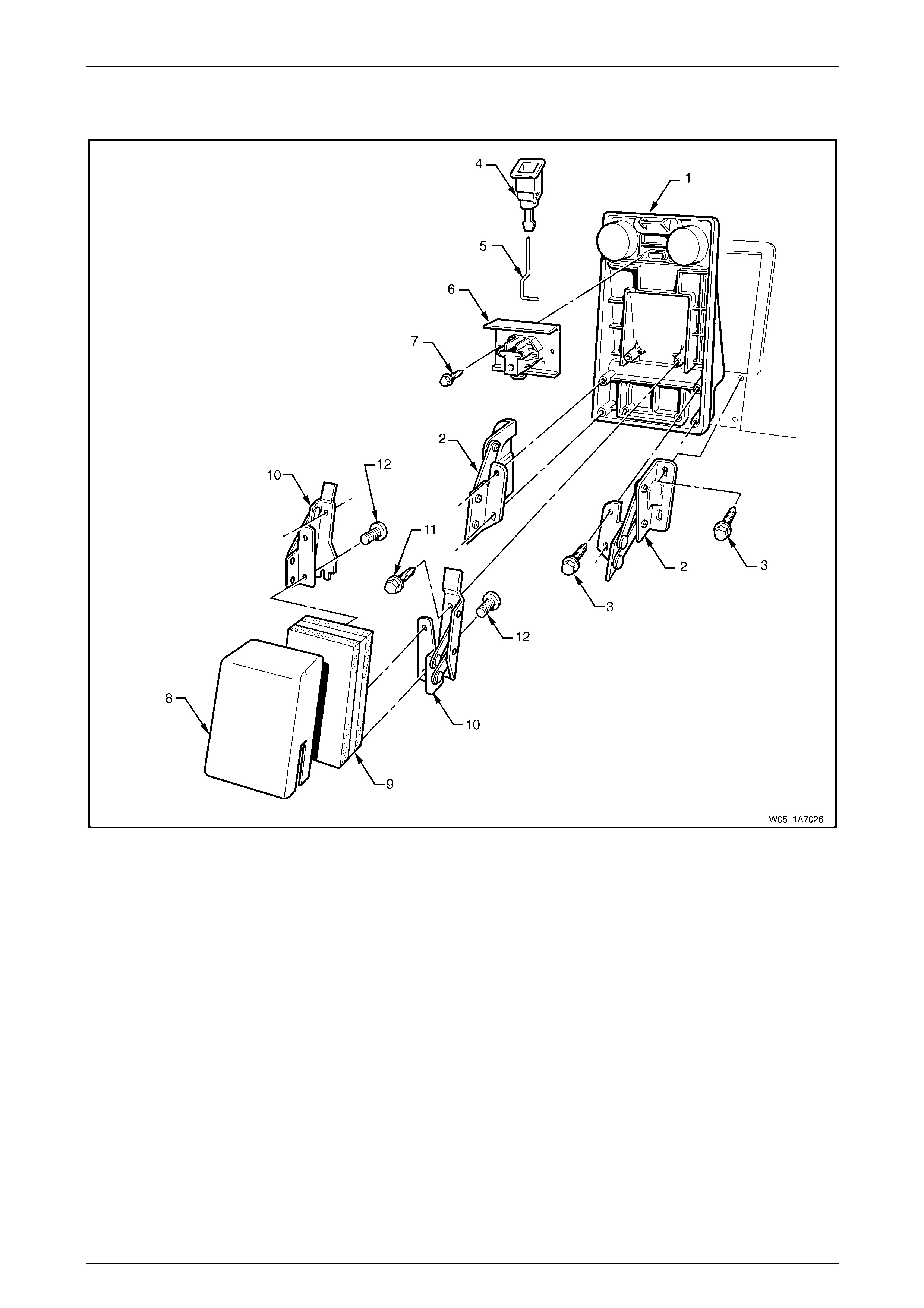
Seat Assemblies Page 1A7A–254
Page 1A7A–254
Rear Seat-back Centre Tray and Armrest Assembly without Compartment
Figure 1A7A – 118
Legend
1 Rear Seat-back Centre Tray
2 Rear Seat-back Centre Tray Hinge
3 Hinge Rear Seat-back Centre Bolt (4 Places)
4 Rear Seat-back Centre Release Button
5 Release Button Rod
6 Rear Seat-back Centre Lock Actuator
7 Lock Actuator Bolt (2 Places)
8 Centre Armrest Cover
9 Centre Armrest Pad
10 Centre Armrest Assembly Hinge
11 Centre Armrest Hinge Bolt (4 Places)
12 Centre Armrest Hinge Screw (4 Places)
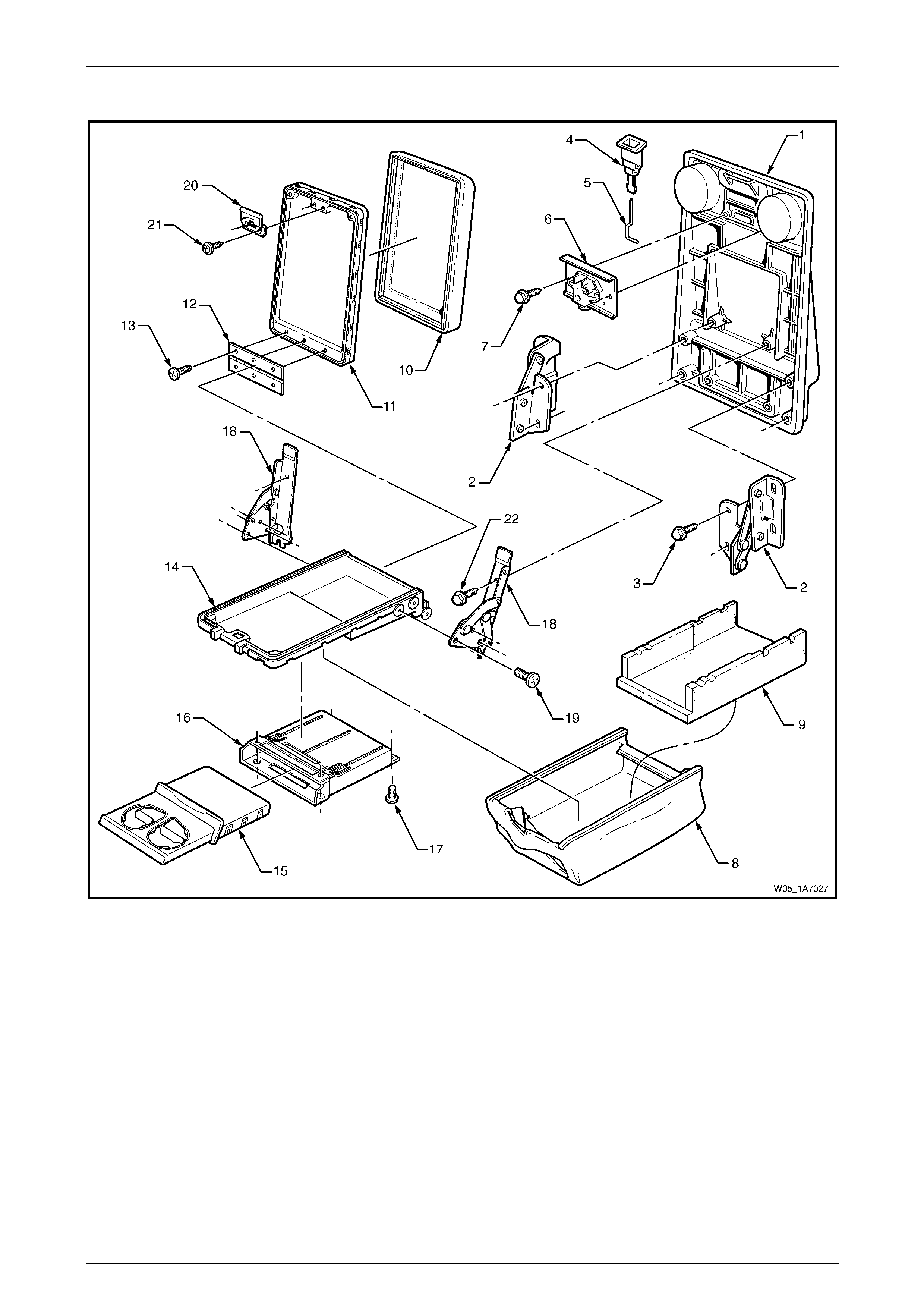
Seat Assemblies Page 1A7A–255
Page 1A7A–255
Rear Seat-back Centre Tray and Armrest Assembly with Compartment
Figure 1A7A – 119
Legend
1 Rear Seat-back Centre Tray
2 Rear Seat-back Centre Tray Hinge
3 Rear Seat-back Centre Hinge Bolt (4 Places)
4 Rear Seat-back Centre Release Button
5 Release Button Rod
6 Rear Seat-back Centre Lock Actuator
7 Lock Actuator Bolt (2 Places)
8 Centre Armrest Cover
9 Centre Armrest Pad
10 Centre Armrest Lid Cover
11 Centre Armrest Lid
12 Centre Armrest Lid Hinge
13 Centre Armrest Lid Hinge Screw (6 Places)
14 Centre Armrest Deposit Box
15 Centre Armrest Cup Holder
16 Centre Armrest Cup Holder Housing
17 Centre Armrest Cup Holder Housing Screw (4 Places)
18 Centre Armrest Assembly Hinge
19 Centre Armrest Hinge Screw (6 Places)
20 Centre Armrest Lid Latch
21 Centre Armrest Lid Latch Screw (2 Places)
22 Centre Armrest Assembly Hinge Bolt (4 Places)
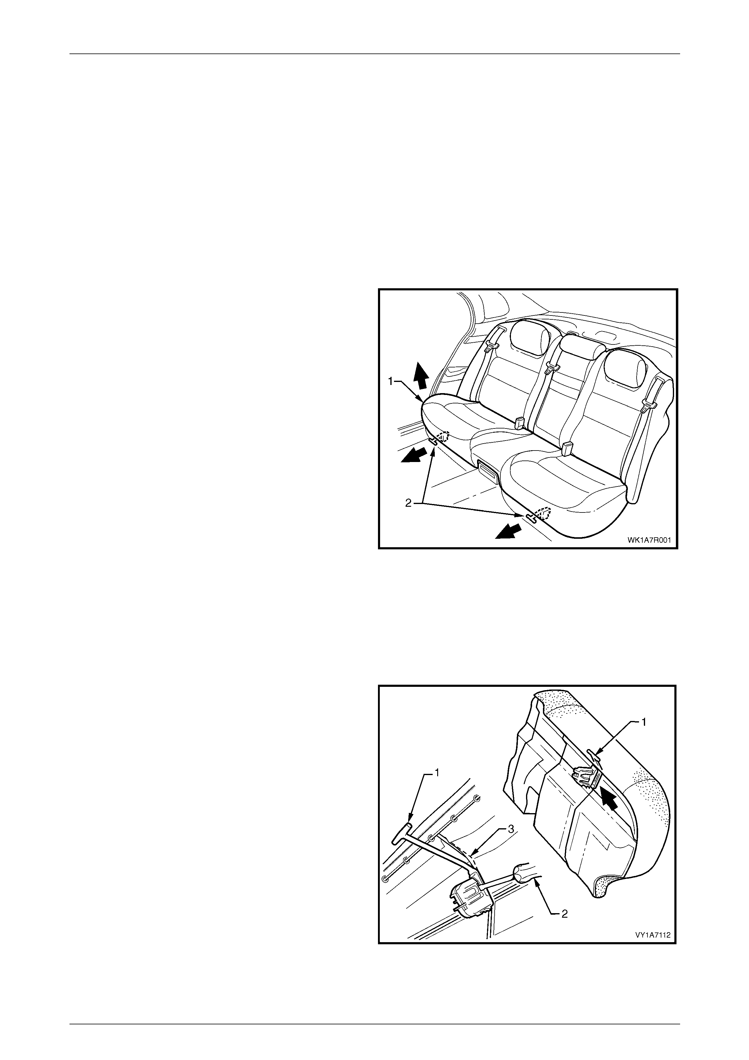
Seat Assemblies Page 1A7A–256
Page 1A7A–256
6.2 Rear Seat Cushion Assembly
LT Section No. – 14-330
Remove
NOTE
If fitted with a DVD, use care when removing the
rear seat cushion to avoid damage to the DVD
control panel cover located under the rear seat
cushion.
1 Lift the front of the rear seat cushion assembly (1)
slightly, to gain access to the rear seat cushion
release handles (2).
2 From either the left or the right side of the seat, pull
the release handle T-piece horizontally forwards, while
at the same time lifting the front of the rear seat
cushion until the lock mechanism is released.
3 Repeat step 2 for the opposite side of the seat.
4 Remove the rear seat cushion assembly.
Figure 1A7A – 120
Disassemble
Rear Seat Cushion Release Handle
Remove
1 Remove the rear seat cushion release handle (1) by
inserting a screwdriver (2) to disengage the retaining
lugs.
2 Slide the release handl e off the rear seat cushion wire
frame (3).
Figure 1A7A – 121
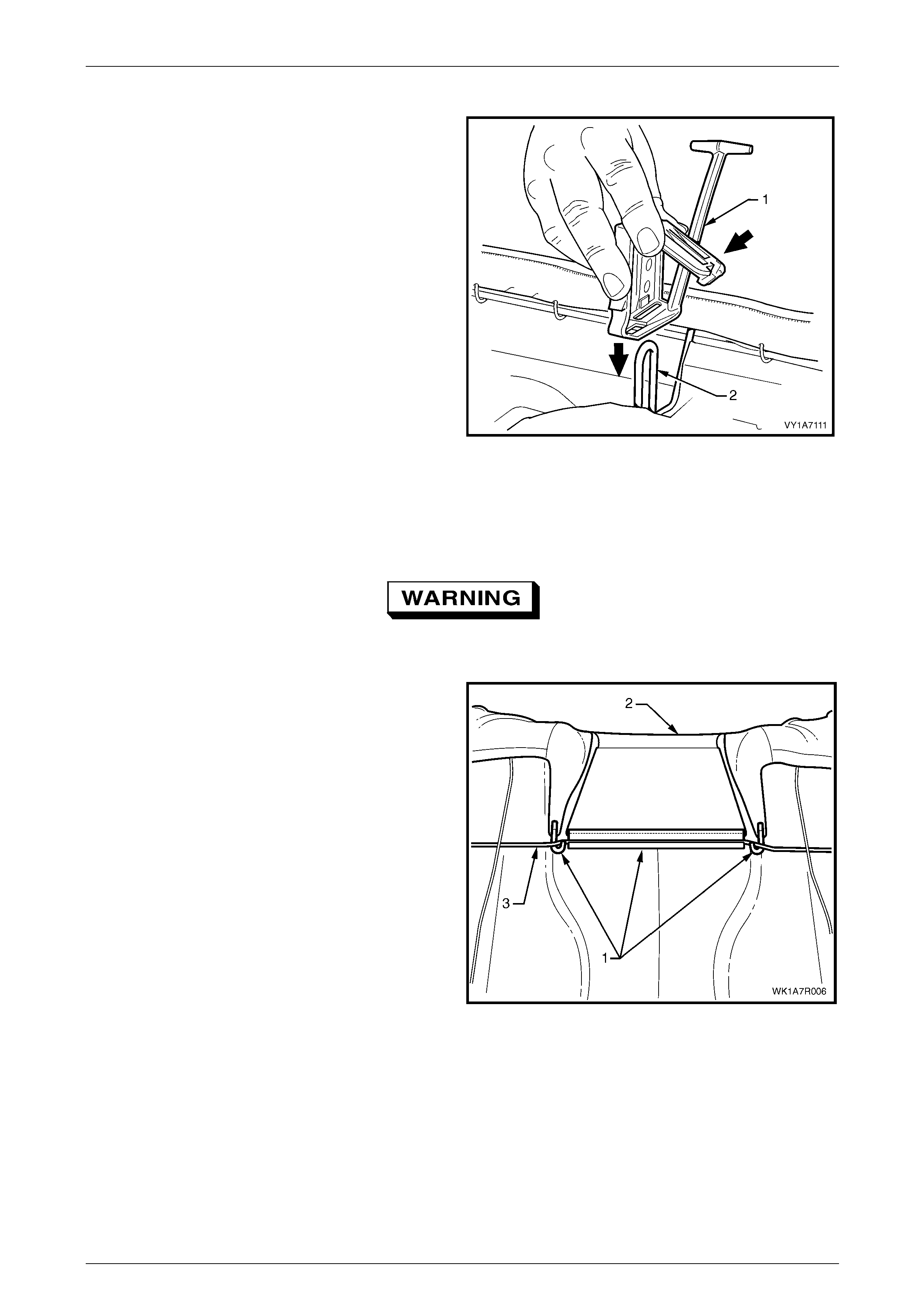
Seat Assemblies Page 1A7A–257
Page 1A7A–257
Reinstall
Slide the rear seat cushion rel ease handle (1) onto the rear
seat cushion wire frame (2) and close the cover so that it will
lock into position on the frame.
Figure 1A7A – 122
Rear Seat Cushion Frame
Remove
Safety glasses an d work glo ves must be w orn
at all times when removing the hog rings.
1 With the rear seat cushion assembly upside down,
follow the procedures below for the appropriate rear
seat type assembly.
a For rear seat Types 3 and 4, unclip the three
retainers (1) attaching the rear seat cushio n
cover (2) to the rear seat cushion frame (3).
b For other rear seat Types, proceed to step 2.
Figure 1A7A – 123
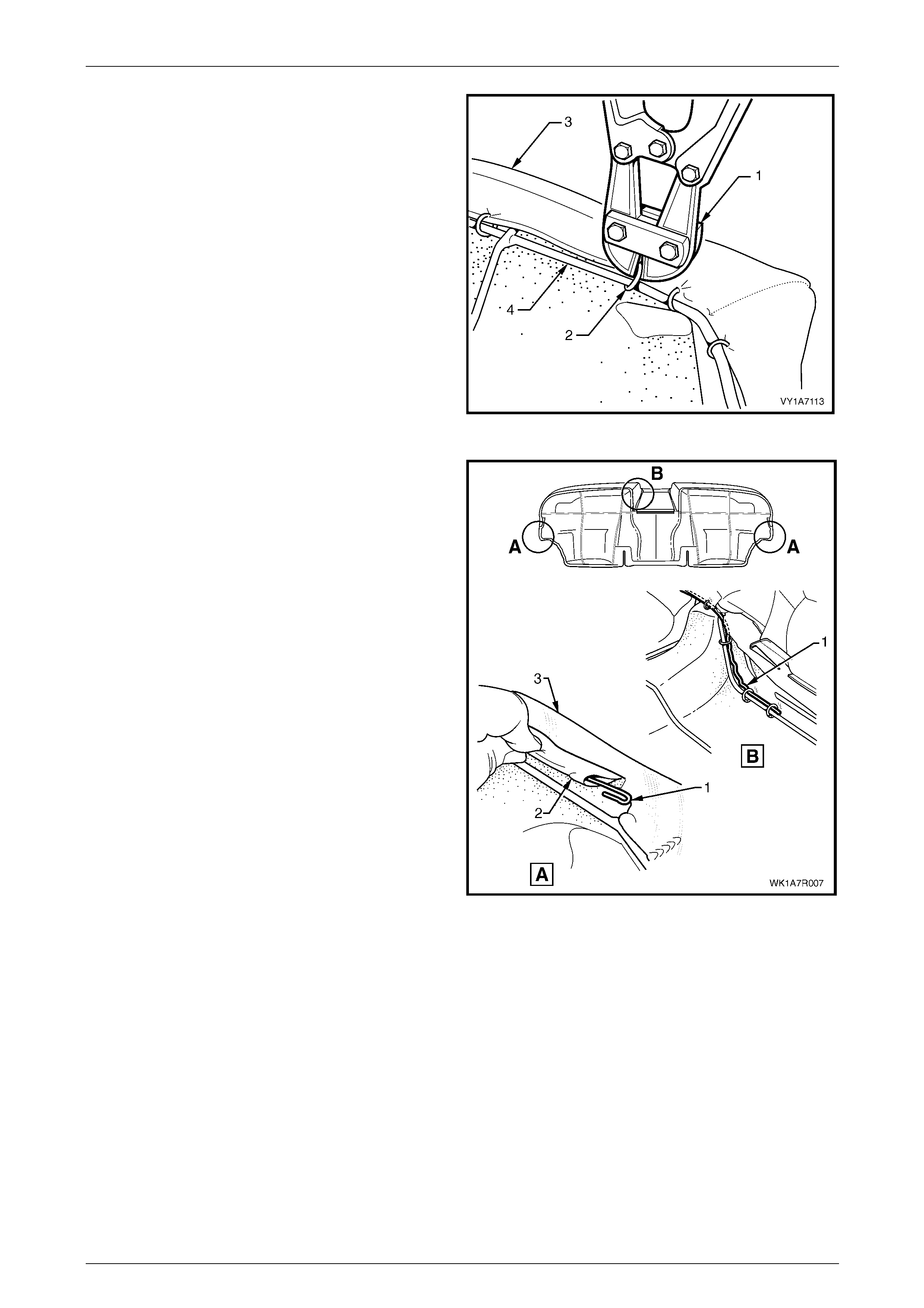
Seat Assemblies Page 1A7A–258
Page 1A7A–258
2 Use bolt cutters or side cutters (1) to remove the hog
rings (2) attaching the cover and pad assem bly (3) to
the frame (4).
• 51 places for the Surebond rear seat Type 5
cushion.
• 54 places for the hook and loop rear seat Type 8
cushion.
• 59 places for the conventional Pull-down rear
seat cushion, all other Types.
NOTE
Care must be taken when removing the hog
rings not to damage the cushion cover. All hog
rings will be destroyed during this operation and
must be replaced.
3 Remove the frame from the rear seat cushion
assembly. Figure 1A7A – 124
4 If required, remove the retaining wire (1) from the
casing (2) attached to the cushion cover assembly (3),
refer, View A only for rear seat Types 1, 2 & 5 to 8 and
Views A and B for rear seat Types 3 and 4.
NOTE
For rear seat Types 3 and 4, the retaini ng wire is
in two pieces with the break in the wire across
the front of the seat.
Figure 1A7A – 125
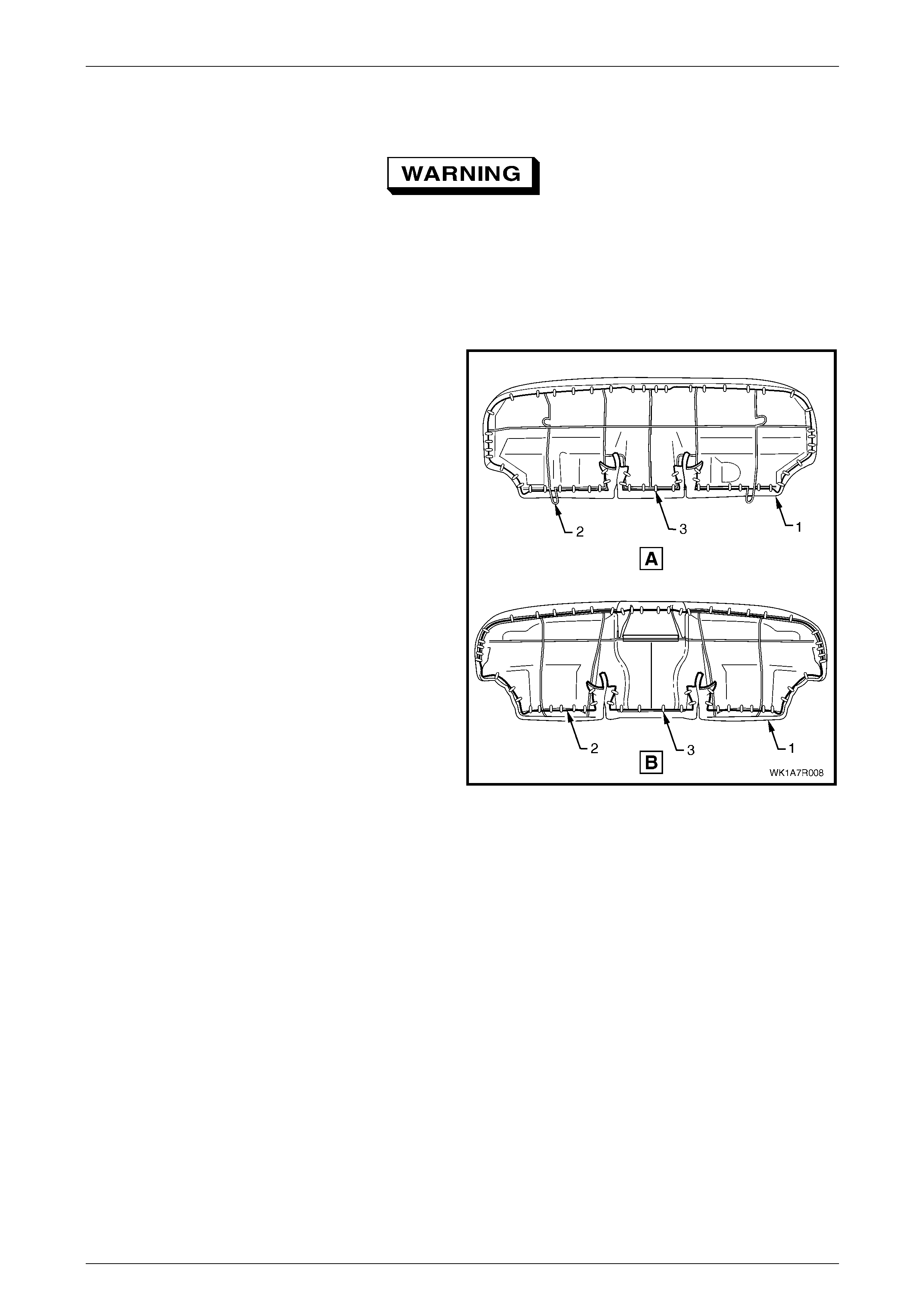
Seat Assemblies Page 1A7A–259
Page 1A7A–259
Reinstall
Safety glasses an d work glo ves must be w orn
at all times when working with hog rings.
NOTE
All hog rings must be replaced when reinstalling
the rear seat cushion frame.
Using the following sequence of operations, align the rear
seat cushion cover and pad assembly (1) to the rear seat
cushion frame (2) and attach the hog rin gs (3 ).
• 51 places for the Surebond rear seat cush ion,
rear seat Type 5.
• 54 places for the hook and loop rear seat cushion,
rear seat Type 8.
• 59 places for the conventional pull down rear seat
cushion, all other rear seat Types.
Figure 1A7A – 126
NOTE
For rear seat Types 3 and 4, the rear seat
cushion cover retaining wire is a two-piece wire.
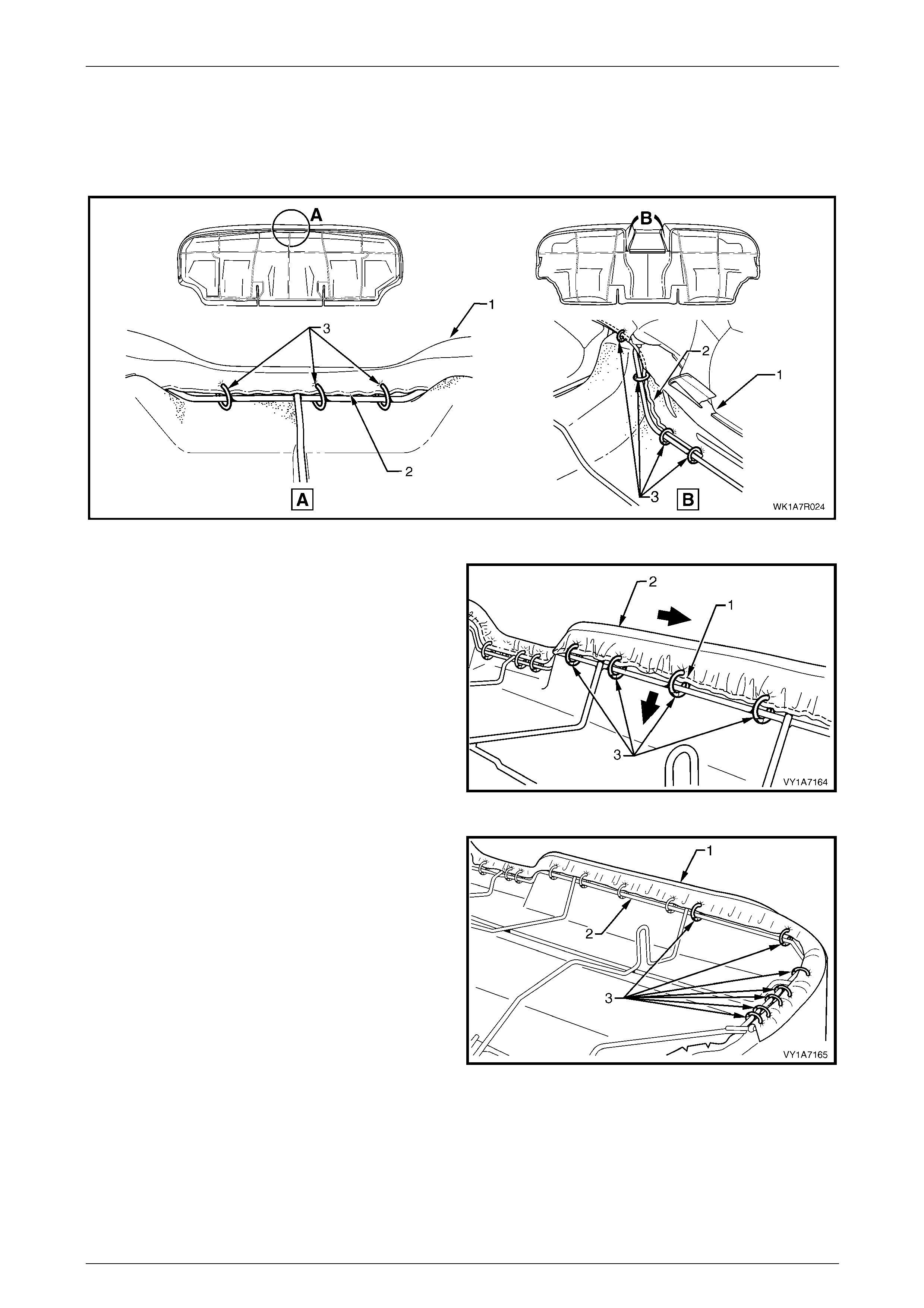
Seat Assemblies Page 1A7A–260
Page 1A7A–260
1 Starting at the front, centre of the rear seat cushion cover assembly (1), attach the wire retainer (2) with the
appropriate number of hog rings (3), refer to F igure 1A7A – 127.
a Three places for rear seat Types 1, 2 & 5 to 8, View A.
b Four places for rear seat Types 3 and 4, View B, each side.
Figure 1A7A – 127
2 Working from the centre outward, attach the wire
retainer (1), while pulling the cover assembly (2) tight
and attach with four hog rings (3).
3 Repeat this process in the opposite direction working
from the centre outward.
Figure 1A7A – 128
4 Continue attaching the cover assemb ly (1) to the
frame (2), by pulling the cover tight and attach with
seven hog rings (3).
5 Repeat this process in the opposite direction.
Figure 1A7A – 129
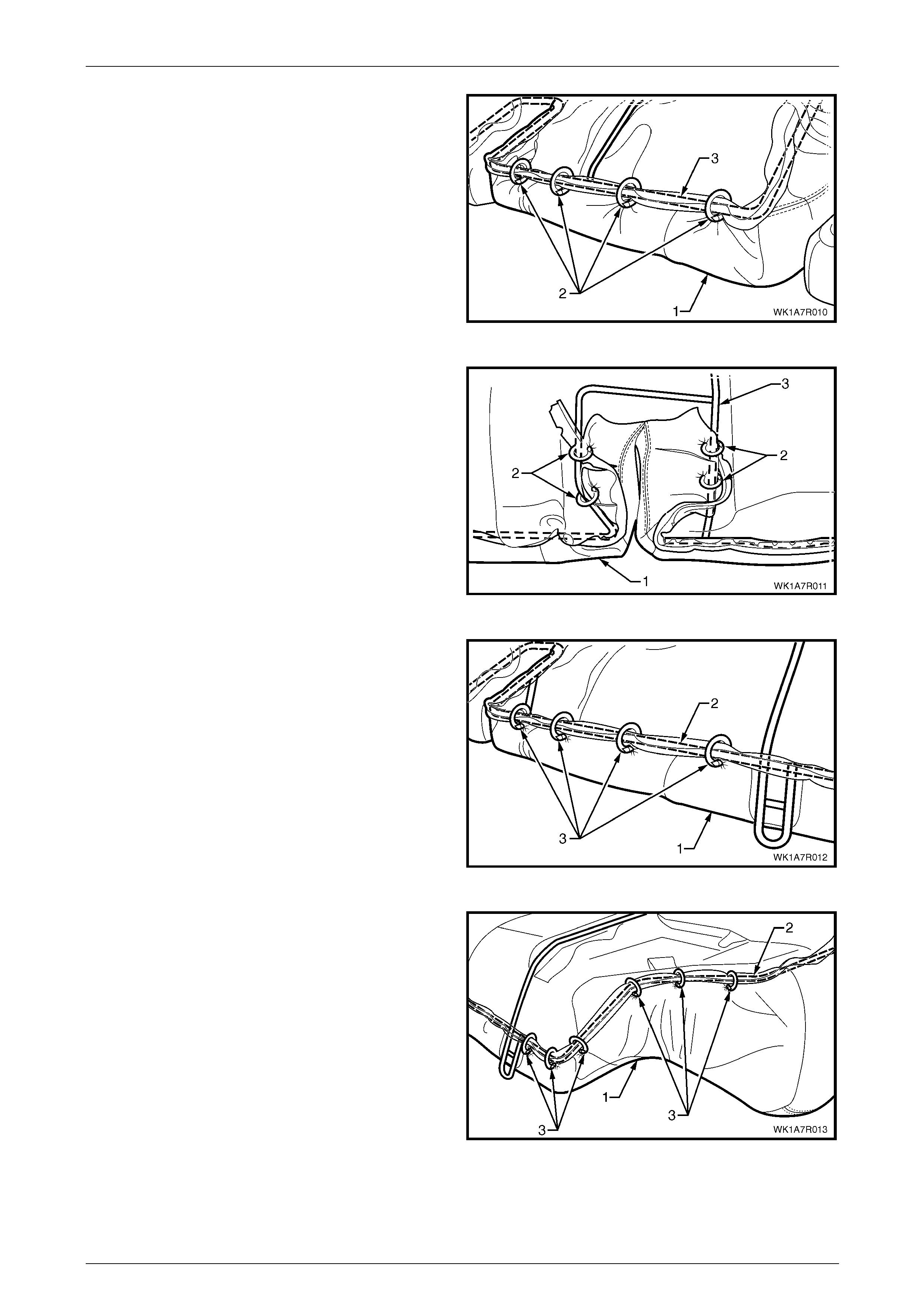
Seat Assemblies Page 1A7A–261
Page 1A7A–261
6 Pull the rear of the cover assembly (1) tight and attach
the centre with four hog rings (2) to the centre of the
wire frame (3).
Figure 1A7A – 130
7 Pull the cushion cover assembl y (1) tight into the
seatbelt slot at the rear and attach with four hog rings
(2) to the wire frame (3).
8 Repeat this process for the opposite seatbelt slot.
Figure 1A7A – 131
9 Working outward from the seatbelt slot, continue
attaching the cover assembly (1) to the frame (2), by
pulling the cover tight and attach with four hog rings
(3).
10 Repeat this process in the opposite dir ection.
Figure 1A7A – 132
11 At the rear corner continue attaching the cover
assembly (1) to the frame (2), by pulling the cover
tight, up and around the corner and attach with six hog
rings (3).
12 Repeat this process for the opposite cor ner.
NOTE
The cover should be smooth and without
creases. If this is not the case, extra hog rings
should be used to pull the cover into place.
Figure 1A7A – 133
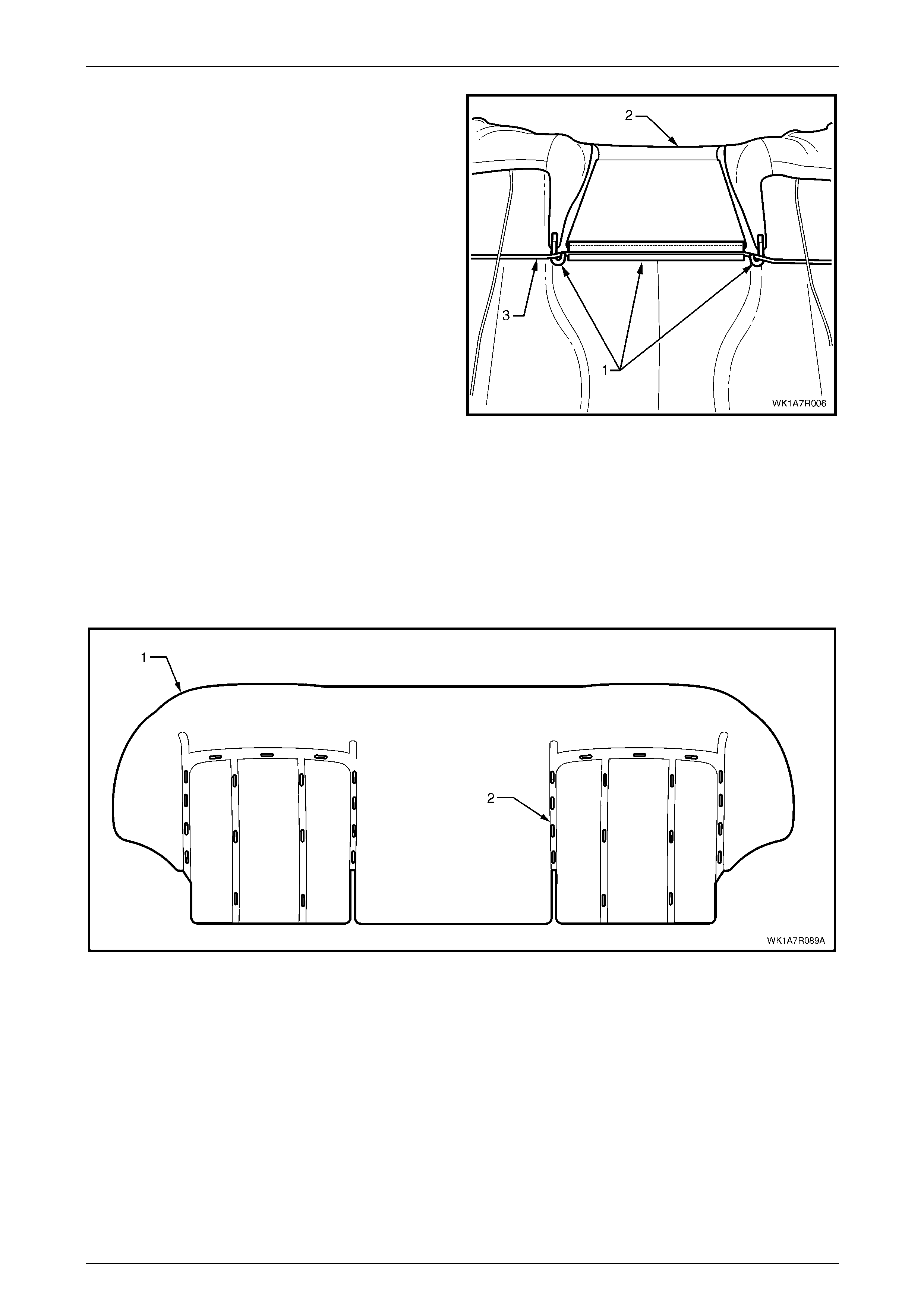
Seat Assemblies Page 1A7A–262
Page 1A7A–262
13 For rear seat Types 3 and 4, reinstall the three
retainers (1) attaching the rear seat cushio n cover (2)
to the rear seat cushion frame (3).
Figure 1A7A – 134
Cushion Cover Assembly
Rear Seat Type 1 and 6
Remove
The cloth rear seat cushion cover for the rea r seat Type 1 and 6 cushion pad (1) is attached with approximately 34 hog
rings (2), in the locations shown, refer to Figure 1A7A – 135.
Figure 1A7A – 135
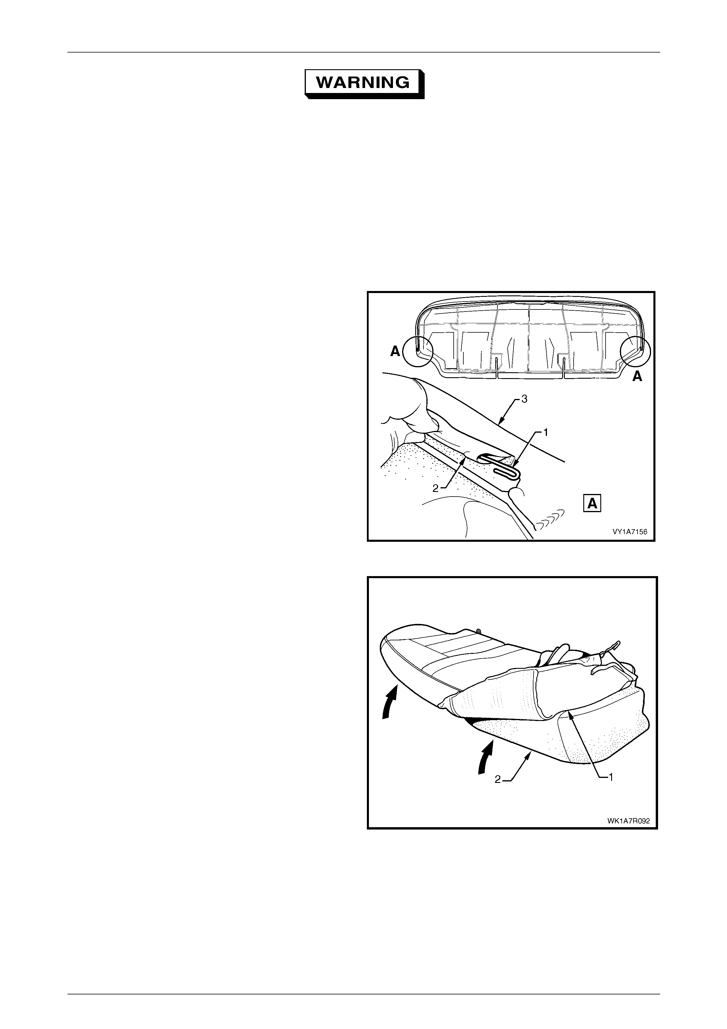
Seat Assemblies Page 1A7A–263
Page 1A7A–263
Safety glasses an d work glo ves must be w orn
at all times when removing the hog rings.
NOTE
Care must be taken when removing the hog rings
not to damage the cushion cover. All hog rings
will be destroyed during this operation and must
be replaced.
Using the following sequenc e of operations, cut the hog rings as they are revealed using bolt cutters or side cutters.
1 If required, remove the rear seat cushion frame, refer to Rear Seat Cushion Frame.
2 If required, remove the retaining wire (1) from the
casing (2) attached to the cushion cover assembly (3).
Figure 1A7A – 136
3 Fold the rear corner of the rear seat cushion cover (1)
over the seat cushion pad (2), then fold the front
corner of the cover up.
Figure 1A7A – 137
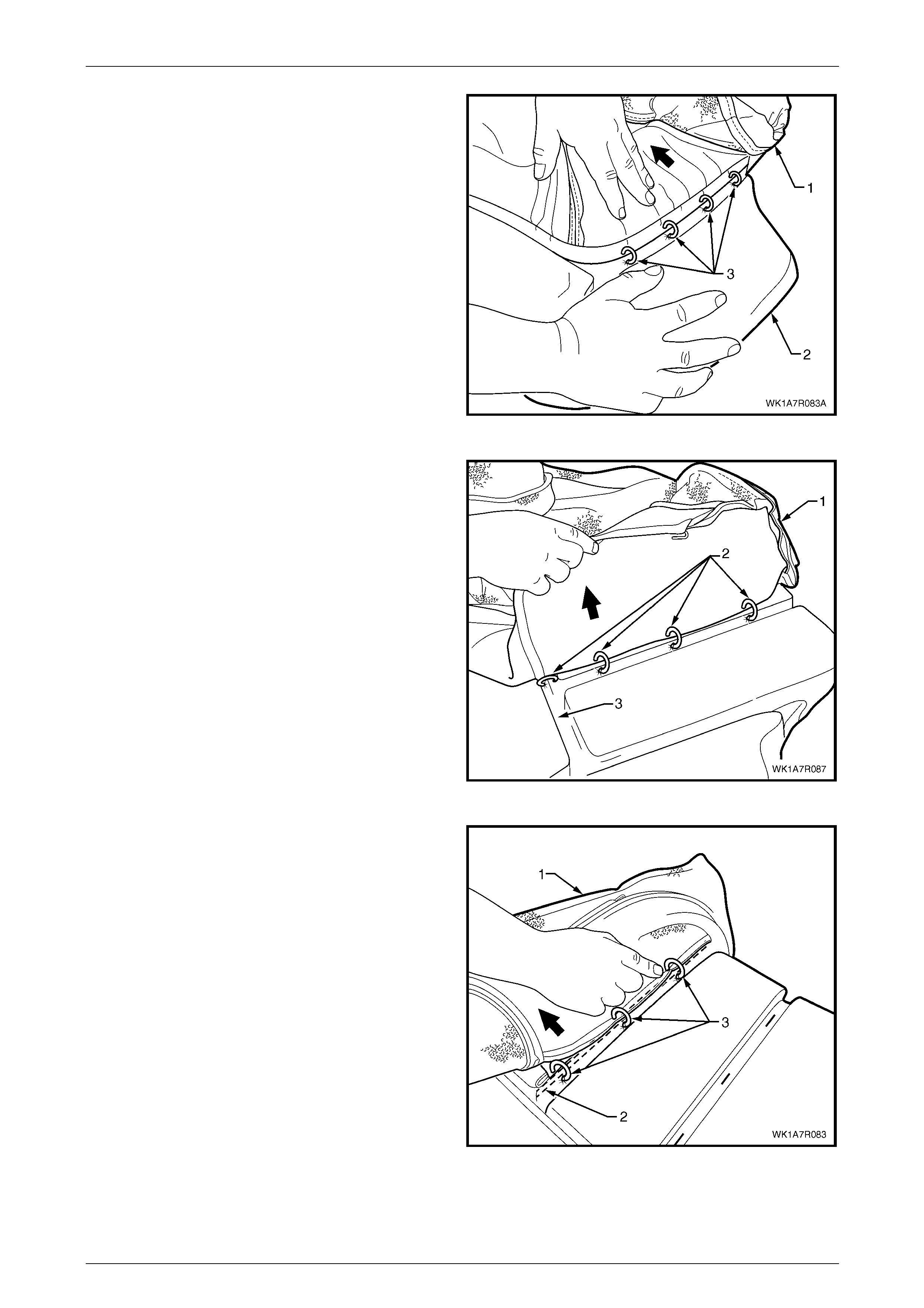
Seat Assemblies Page 1A7A–264
Page 1A7A–264
4 From the outer edge, continue to fold the cushion
cover (1) back while holding the cushion pad (2)
revealing the four hog rings (3) attaching th e outer
retaining wire to the pad and cut the hog rings.
Figure 1A7A – 138
5 Working towards the centre of the seat cushion,
carefully fold back the cover (1) revealing the hog
rings (2) attaching the inner and front retaining wires to
the pad. Cut these and continue folding the cover back
until all hog rings in the correspondin g grooves (3)
have been removed.
Figure 1A7A – 139
6 Continue to fold the cushion (1) over towards the
centre and from the front of the rear seat cushion (2).
Cut the three hog rings (3) attaching the inner
retaining wire to the pad.
7 Repeat the process for the centre groove.
8 Repeat the process for the other side of the rear seat
cushion.
9 Remove the cushion cover from the cushion.
Figure 1A7A – 140
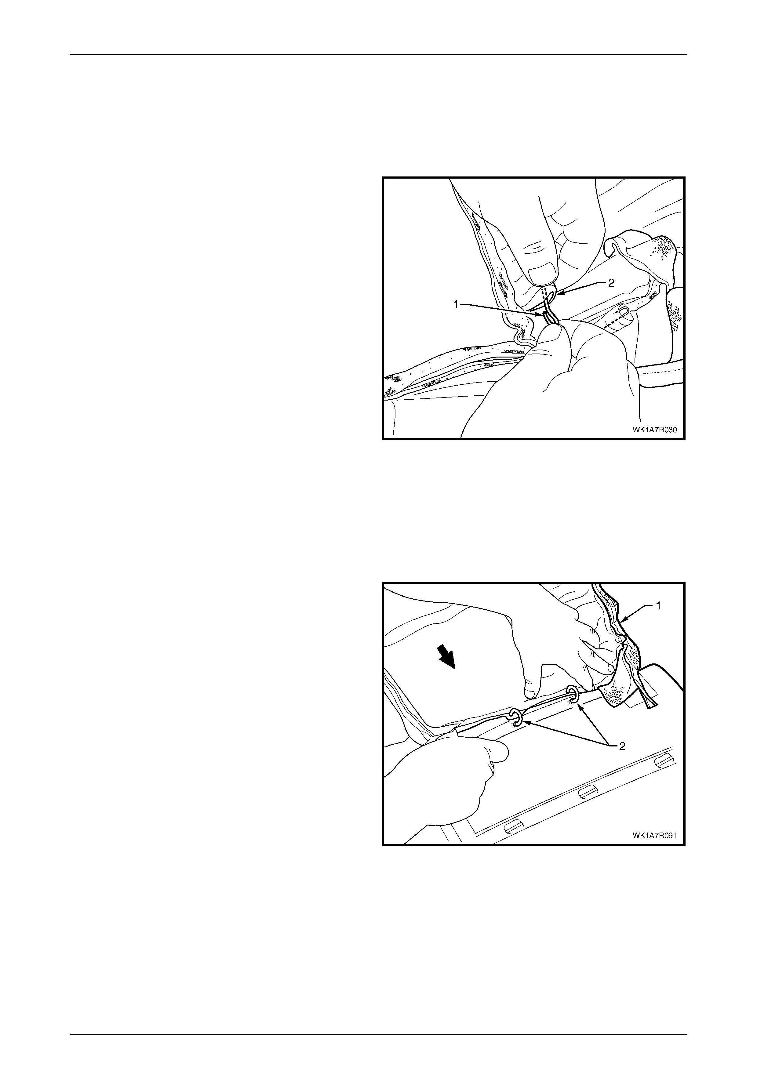
Seat Assemblies Page 1A7A–265
Page 1A7A–265
NOTE
The cushion cover has ten retaining wires that
align the cushion cover to the cushion pad and
are used to hook the hog rings to. These will
need to be removed from the cover if it is to be
replaced.
10 If required, remove the retaining wire (1) from the
casing (2) and repeat for the remaining nine places.
Figure 1A7A – 141
Reinstall
Referring to Figure 1A7A – 135 showing the hog ring locations, reinstall the rear seat cus hion cover using the following
sequence of operations, attachin g the hog rings with hog ring pliers.
1 If required, reinstall the retaining wire (1) into the casing (2), ten places, in the cushion cover assembl y, refer to
Figure 1A7A – 141.
2 Beginning on one side of the cushion, position the
cover (1) into the inner corresponding groove.
NOTE
Ensure the cushion cover aligns to all the
grooves in the cushion pad before attaching the
cover with hog rings.
3 Starting at the rear and working towards the front,
attach hog rings (2), four places, using hog ri ng pliers.
Figure 1A7A – 142
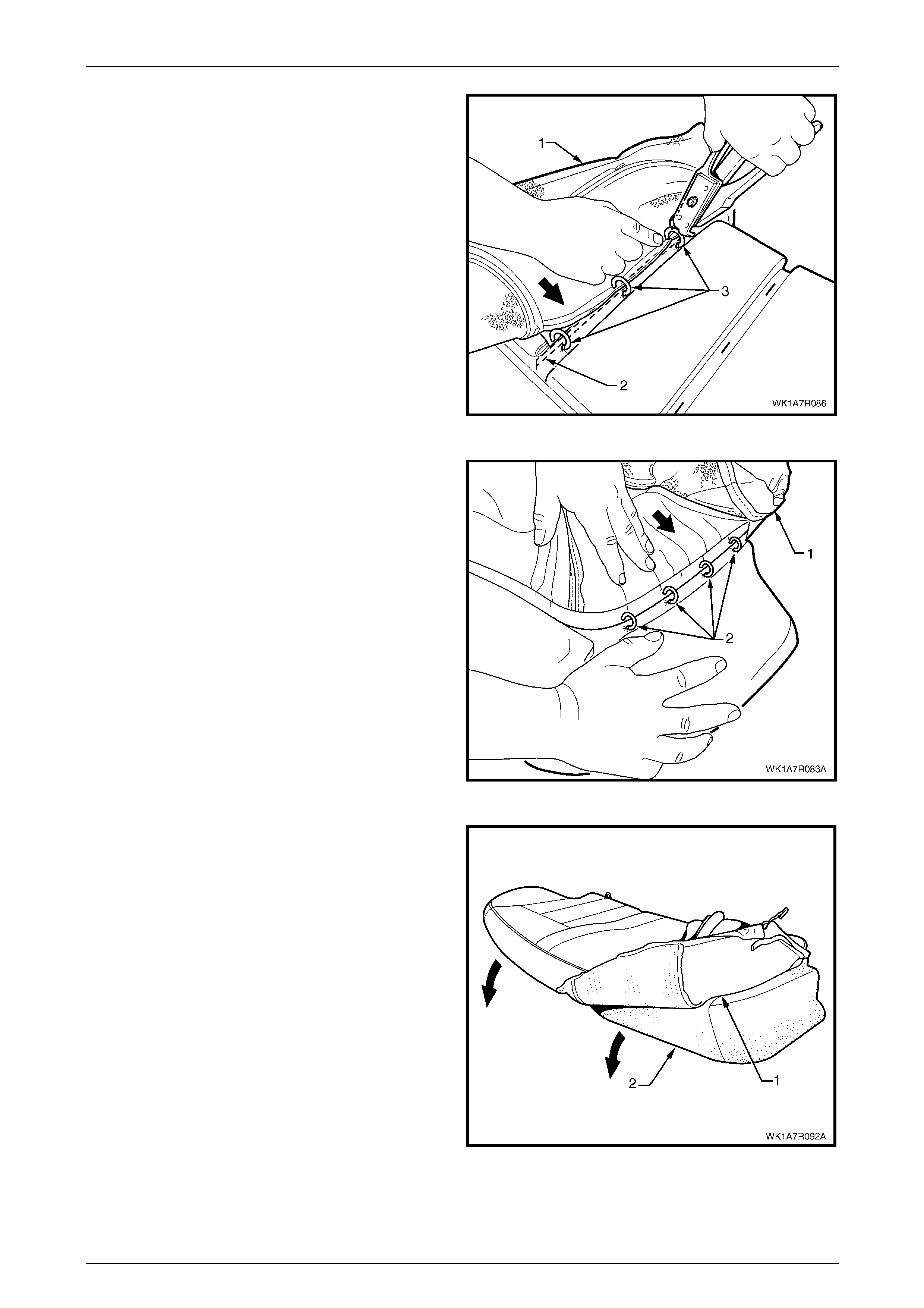
Seat Assemblies Page 1A7A–266
Page 1A7A–266
4 Continue working towards the outside e dg e of the
cushion, fold the cushion cover (1) into the centre
corresponding groove (2) an d attach the cover with
three hog rings (3).
5 Repeat for the other centre corresponding groove.
6 Position the cover into the front corresponding cushion
groove and attach with three hog rings usi ng the same
method as for the centre grooves.
Figure 1A7A – 143
7 Working along the side of the rear seat cush ion,
position the cover (1) into the outer correspo nding
groove and attach four hog rings (2).
8 Repeat the process for the opposite side of the rear
seat cushion cover.
Figure 1A7A – 144
9 Fold the rear seat cushion cover (1) over the corners
of the cushion pad (2).
10 Pull the rear seat cushion cover up over th e rear seat
cushion ensuring that the cushion cover is fitted neatly
into all corners and contours of the rear seat cushion.
Figure 1A7A – 145
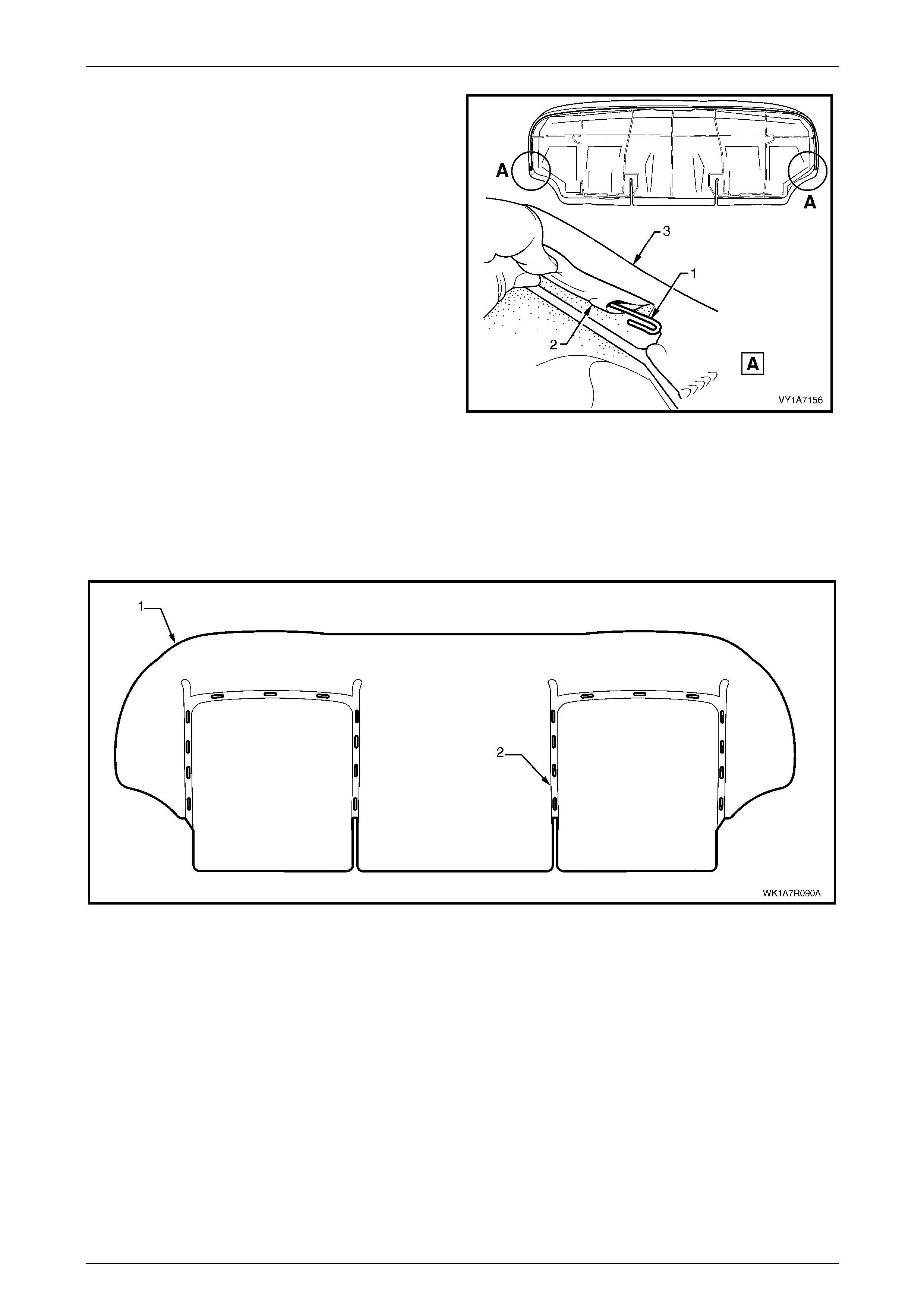
Seat Assemblies Page 1A7A–267
Page 1A7A–267
11 If removed, reinstall the retaining wire (1) from the
casing (2) attached to the cushion cover assembly (3).
12 Refit the rear seat cushion frame, refer to
Rear Seat Cushion Frame.
Figure 1A7A – 146
Rear Seat Type 2 and 7
Remove
The leather rear seat cushion cover for rear s eat Types 2 and 7 cushion pad (1) is, attached to the cushion with
approximately 28 hog rings (2) in the locations shown, refer to Figure 1A7A – 147.
Figure 1A7A – 147
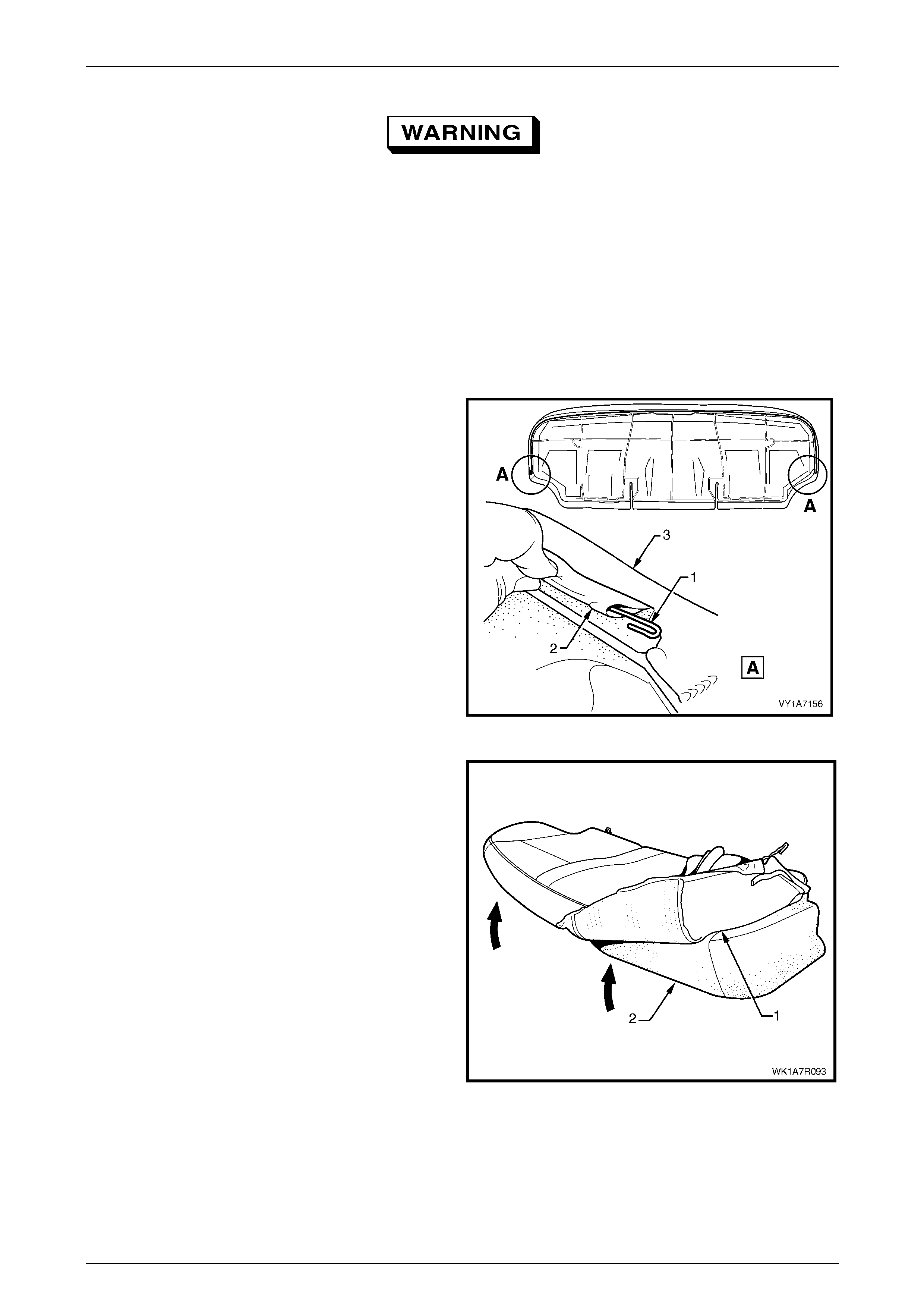
Seat Assemblies Page 1A7A–268
Page 1A7A–268
Safety glasses an d work glo ves must be w orn
at all times when removing the hog rings.
NOTE
Care must be taken when removing the hog rings
not to damage the cushion cover. All hog rings
will be destroyed during this operation and must
be replaced.
Using the following sequenc e of operations, cut the hog rings as they are revealed using bolt cutters or side cutters.
1 If required, remove the rear seat cushion frame, refer to Rear Seat Cushion Frame.
2 If required, remove the retaining wire (1) from the
casing (2) attached to the cushion cover assembly (3).
Figure 1A7A – 148
3 Pull the rear corner of the rear seat cushion cover (1)
over the seat cushion pad (2) and the n pull the front
corner of the cover up.
Figure 1A7A – 149
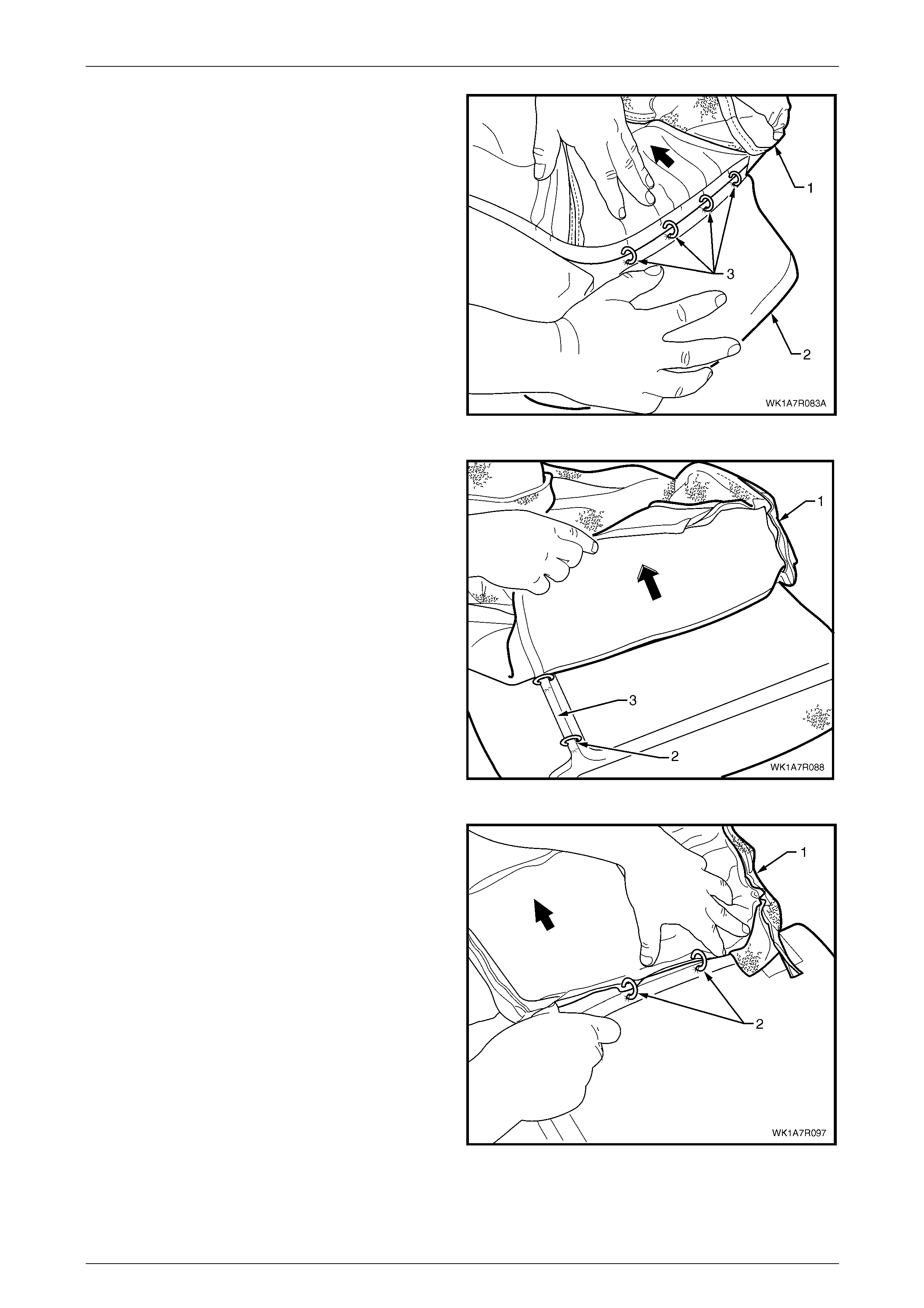
Seat Assemblies Page 1A7A–269
Page 1A7A–269
4 Fold the cushion cover (1) towards the centre of the
cushion while holding the cushion pad (2) revealing
the four hog rings (3) and cut to remove.
Figure 1A7A – 150
5 Working towards the centre of the rear seat cushion,
carefully fold back the cover (1) revealing the outer
hog ring (2), cut this and continue folding the cover
back until all hog rings in the corresponding groove (3)
have been removed.
Figure 1A7A – 151
6 Continue to fold the cushion over towards the centre
and from the rear of the seat cushion, cut the hog
rings (2), four places, while working towards the front.
7 Repeat steps 3 to 6 for the other side of the rear seat
cushion.
8 Remove the cushion cover from the cushion.
Figure 1A7A – 152
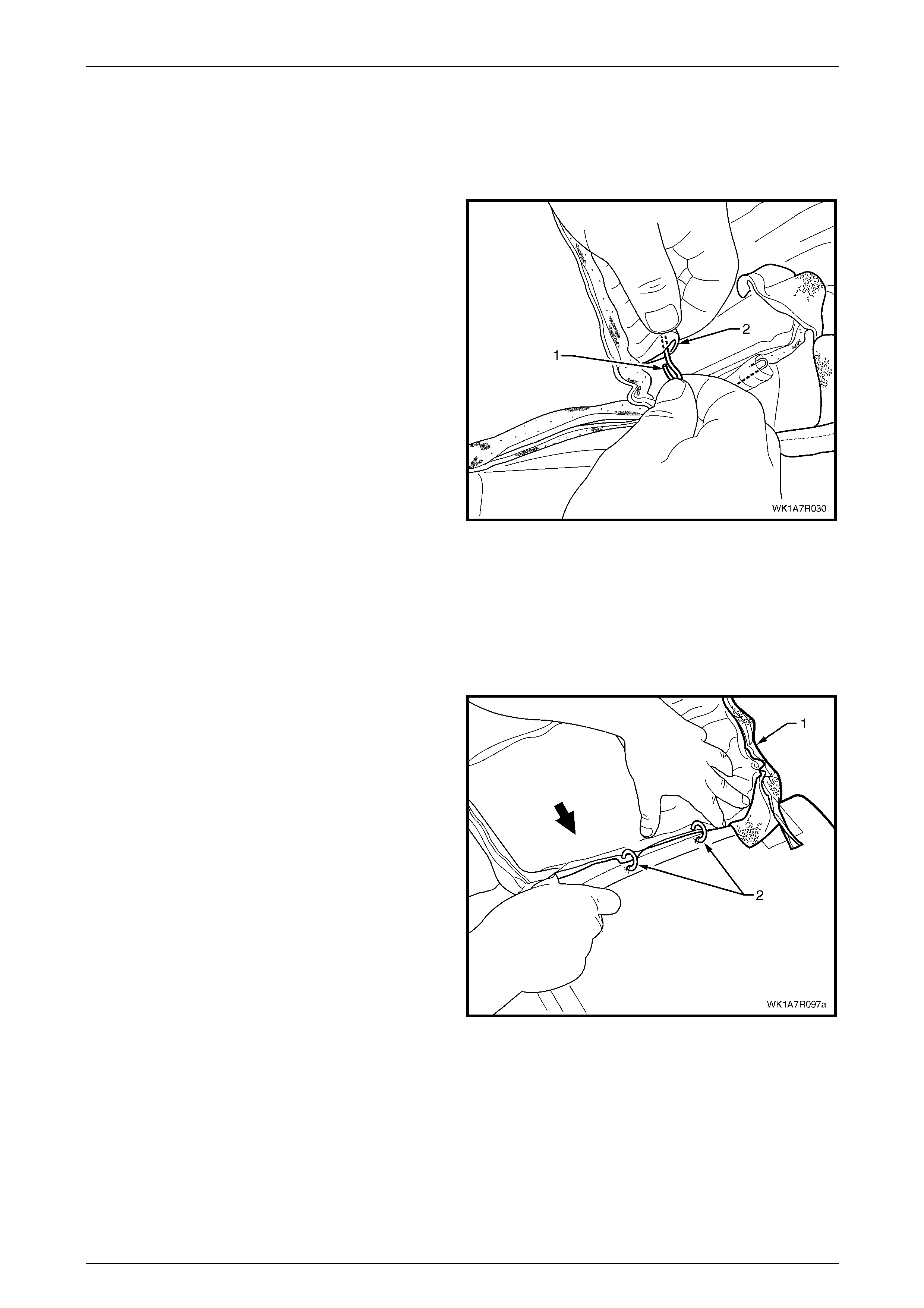
Seat Assemblies Page 1A7A–270
Page 1A7A–270
NOTE
The cushion cover has six retaining wires that
align to the grooves in the cushion pad and are
used to hook the hog rings to. These will need to
be removed from the cover if it is to be replaced.
9 If required, remove the retaining wire (1) from the
casing (2) and repeat for the remaining five places.
Figure 1A7A – 153
Reinstall
Referring to Figure 1A7A – 147 showing the hog ring locations, install the rear seat cushion cover using the following
sequence of operations, attachin g the hog rings with hog ring pliers.
1 If required, reinstall the retaining wire (1) into the casing (2), six places, in the cushion cover assembly, refer to
Figure 1A7A – 153.
2 Beginning on one side of the cushion, position the
cover (1) into the inner corresponding groove. Starting
at the rear and working towards the front, attach with
hog rings (2), four places, using hog ring pli ers.
NOTE
Ensure the cushion cover aligns to all the
grooves in the cushion pad before attaching the
cover with hog rings.
Figure 1A7A – 154

Seat Assemblies Page 1A7A–271
Page 1A7A–271
3 Continue to fold the cushion cover (1) into the front
and outer corresponding groov e (2) of the seat and
working around to the corner, attach the cover with
hog rings (3), four places.
Figure 1A7A – 155
4 Working along the outer edge of the rear seat cushion,
position the cover (1) into the corresponding
groove (2) and attach with four hog rings (3).
5 Repeat the process for the opposite side of the rear
seat cushion cover.
Figure 1A7A – 156
6 Fold the rear seat cushion cover (1) over the corners
of the cushion pad (2) ensuring it is fitted nea tly into all
corners and contours of the rear seat cushion.
NOTE
As part of their designed appearance, Leather
cushion covers have inherent minor creases in
the material.
Figure 1A7A – 157
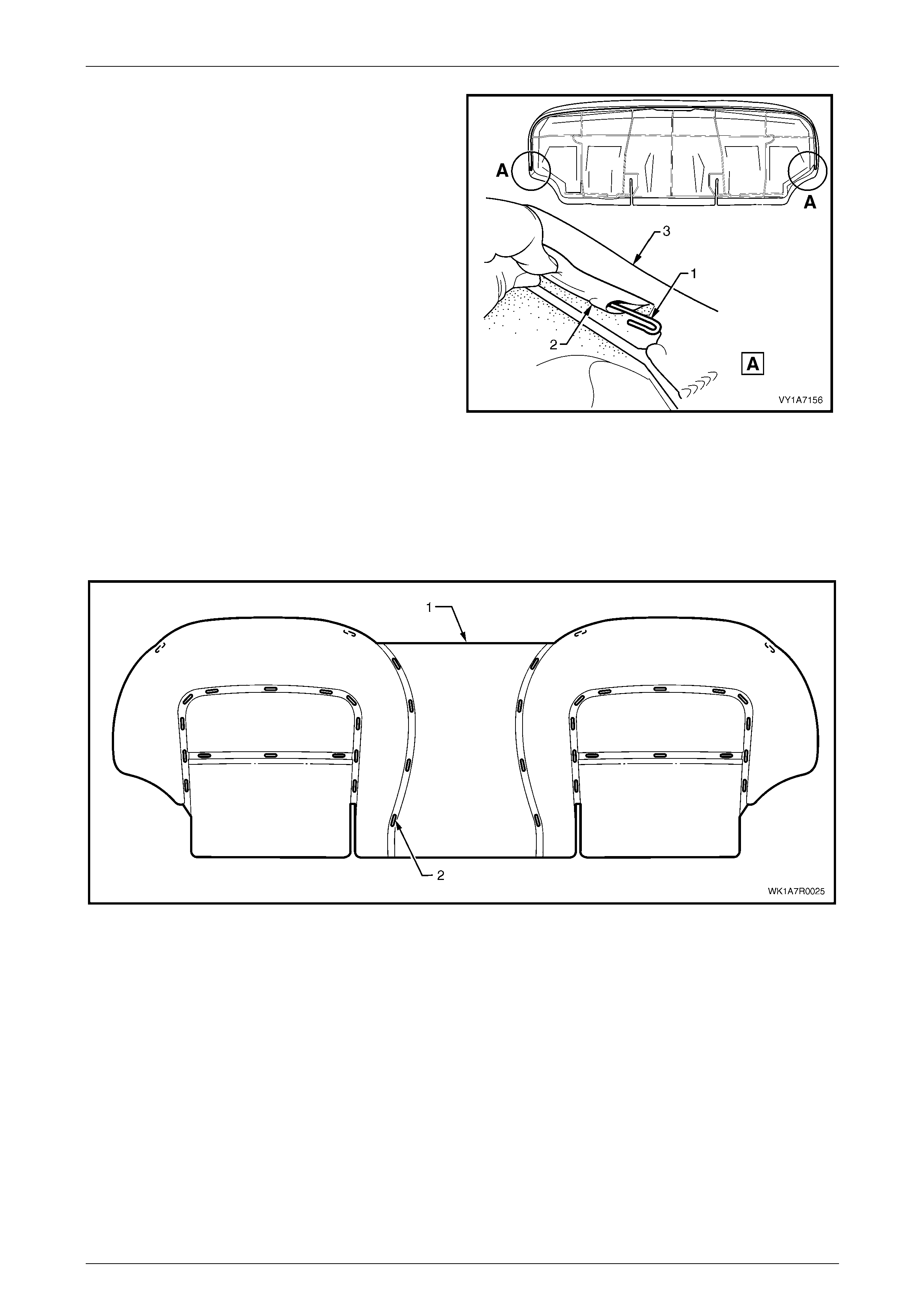
Seat Assemblies Page 1A7A–272
Page 1A7A–272
7 If removed, reinstall the retaining wire (1) from the
casing (2) attached to the cushion cover assembly (3).
8 Refit the rear seat cushion frame, refer to
Rear Seat Cushion Frame.
Figure 1A7A – 158
Rear Seat Type 3
Remove
The rear seat cushion cover (1) for rear seat Type 3 is attached to the cushion with approximatel y 40 hog rings in the
locations shown (2), refer to Figure 1A7A – 159.
Figure 1A7A – 159
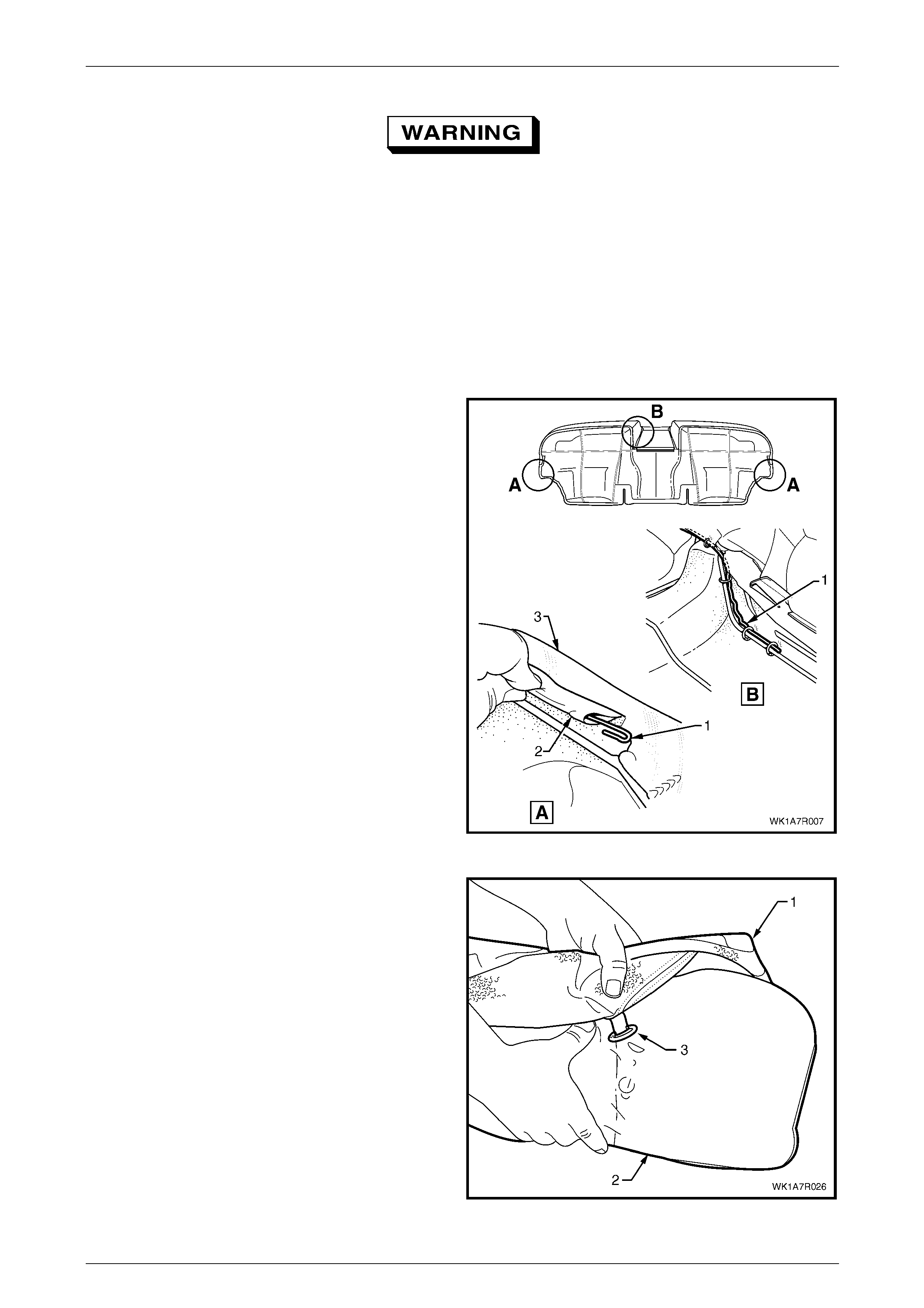
Seat Assemblies Page 1A7A–273
Page 1A7A–273
Safety glasses an d work glo ves must be w orn
at all times when removing the hog rings.
NOTE
Care must be taken when removing the hog rings
not to damage the cushion cover. All hog rings
will be destroyed during this operation and must
be replaced.
Using the following sequenc e of operations, cut the hog rings as they are revealed using bolt cutters or side cutters.
1 If required, remove the rear seat cushion frame, refer to Rear Seat Cushion Frame.
2 If required, remove the retaining wire (1) from the
casing (2) attached to the cushion cover assembly (3).
NOTE
The rear seat Type 3 retaining wire is in two
pieces with the break in the wire across the front
of the seat above the transmission tunnel.
Figure 1A7A – 160
3 Fold the rear corner of the rear seat cushion cover (1)
over the seat cushion pad (2), then fold the front
corner of the cover up revealing the hog ring (3).
Figure 1A7A – 161
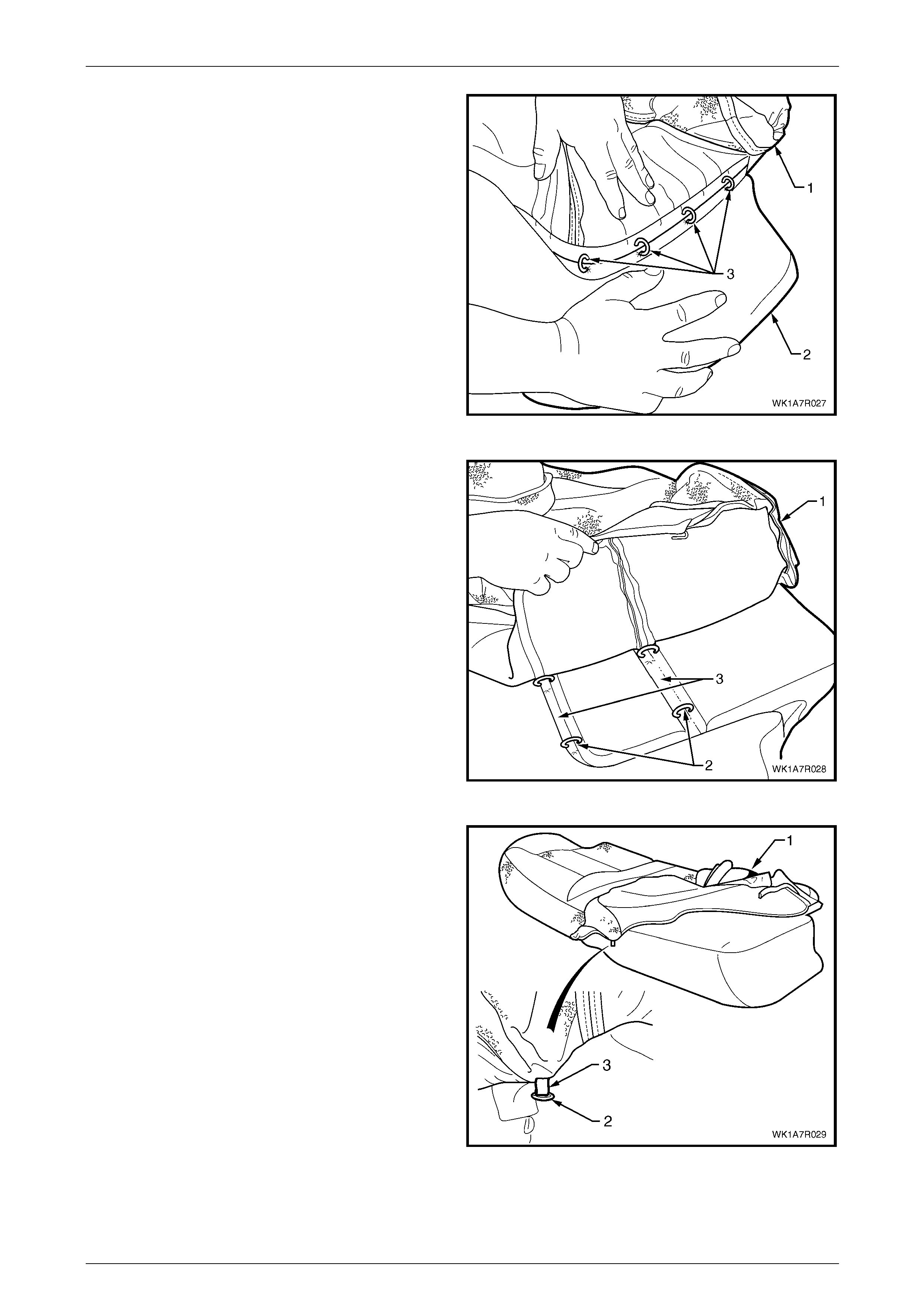
Seat Assemblies Page 1A7A–274
Page 1A7A–274
4 Fold the cushion cover (1) back while holding the
cushion pad (2) revealing the four hog rings (3) and
cut to remove.
Figure 1A7A – 162
5 Working towards the centre of the seat cushion,
carefully fold back the cover (1) revealing two outer
hog rings (2), cut these and continue folding the cover
back until all hog rings in each corresp onding groove
(3) have been removed.
Figure 1A7A – 163
6 Fold the front of the cushion cover (1) back revealing
the hog ring (2) taking care not to damage the cushion
cover tag (3) or the cover and remove the hog ring.
Figure 1A7A – 164
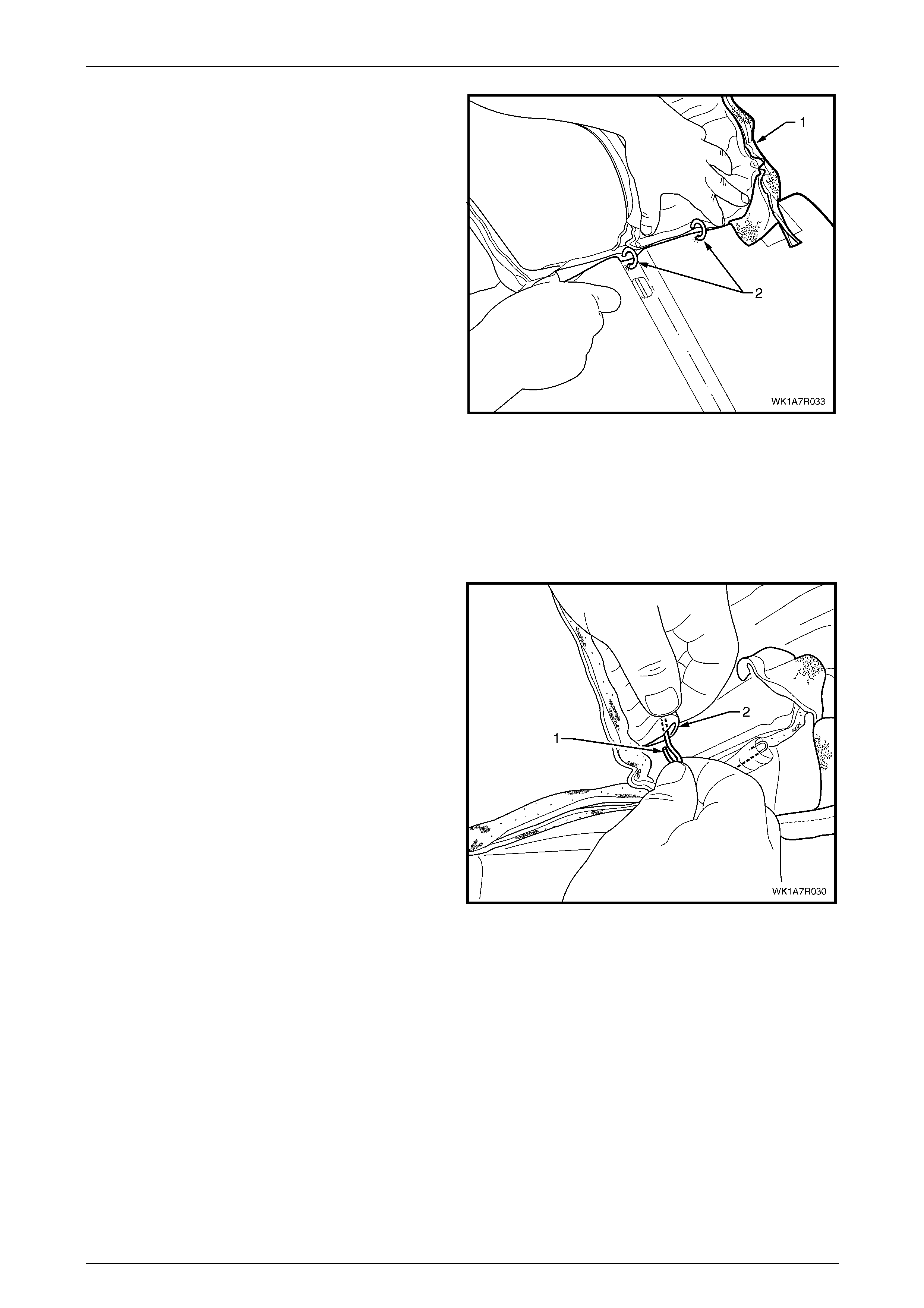
Seat Assemblies Page 1A7A–275
Page 1A7A–275
7 Continue to fold the cushion over towards the centre
and from the rear of the seat cushion, cut the hog
rings (2), four places, while working towards the front.
8 Continue to fold the cushion cover back towards the
centre and repeat the process for the centre groove.
9 Repeat the process for the other side of the rear seat
cushion.
10 Remove the cushion cover from the cushion.
Figure 1A7A – 165
NOTE
The cushion cover has six retaining wires that
align to the grooves in the cushion pad and are
used to hook the hog rings to. These will need to
be removed from the cover if it is to be replaced.
11 If required, remove the retaining wire (1) from the
casing (2) and repeat for the remaining five places.
Figure 1A7A – 166
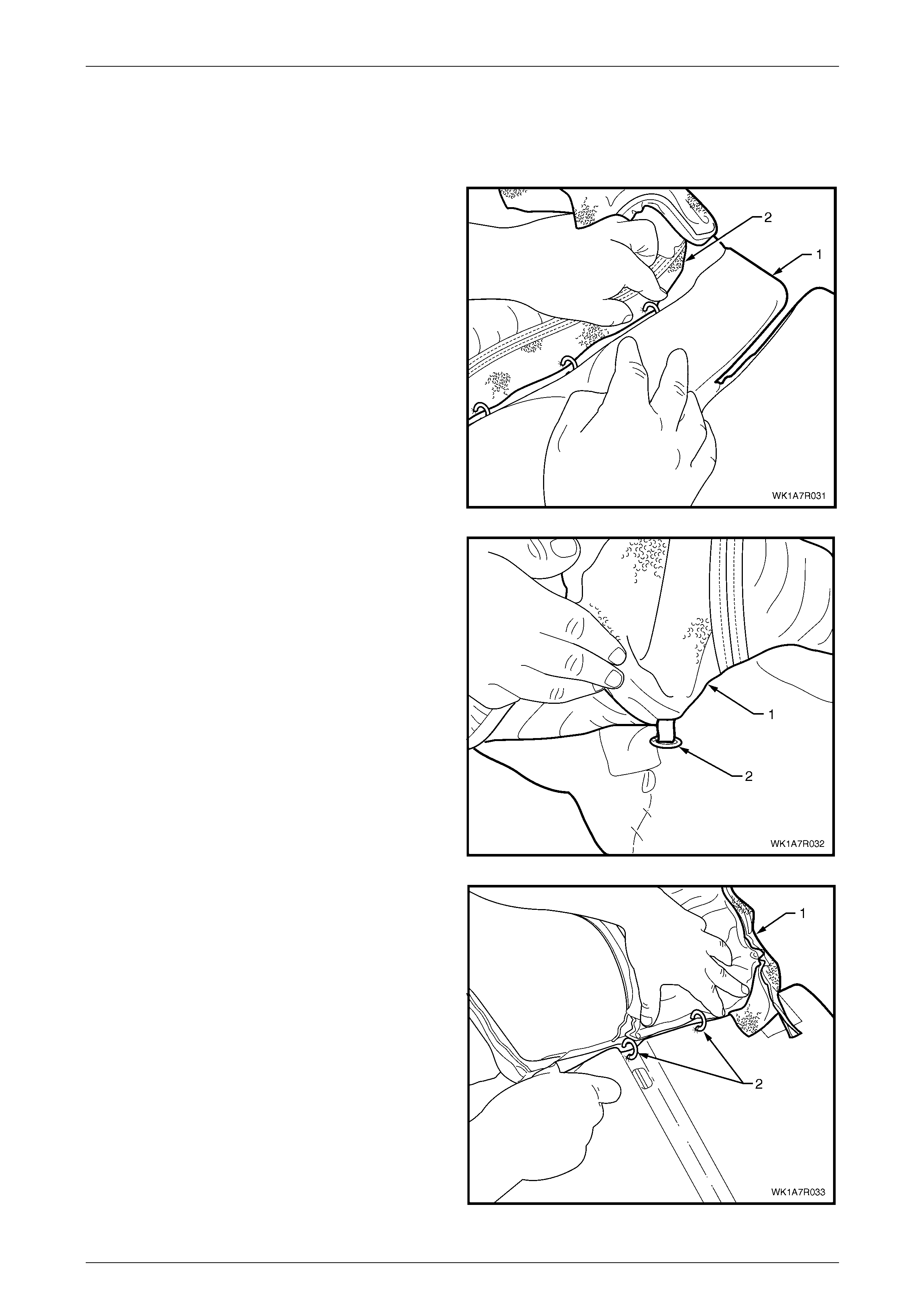
Seat Assemblies Page 1A7A–276
Page 1A7A–276
Reinstall
Referring to Figure 1A7A – 159 showing the hog ring locations, install the rear seat cushion cover using the following
sequence of operations, attachin g the hog rings with hog ring pliers.
1 If required, reinstall the retaining wire (1) into the casing (2) in six locations in the cushion cover assembly, refer to
Figure 1A7A – 166.
2 Beginning on one side of the rear seat cush ion (1)
position the cover (2) into the centre corresponding
groove. Starting at the rear and working to wards the
front, attach with four hog rings using hog ring pliers.
NOTE
Ensure the cushion cover aligns to all the
grooves in the cushion pad before attaching the
cover with hog rings.
Figure 1A7A – 167
3 Working outward, start from the front of the cushion,
fold the cushion cover (1) over the front and attach the
hog ring (2).
Figure 1A7A – 168
4 Fold the cushion cover (1) into the corresponding
groove and from the front of the seat and working
around to the rear, attach the cover with hog rings (2),
four places.
Figure 1A7A – 169
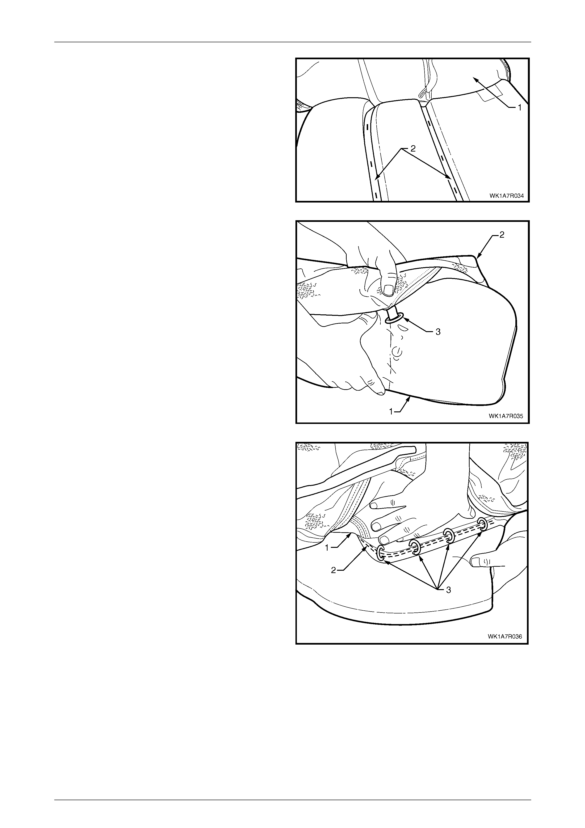
Seat Assemblies Page 1A7A–277
Page 1A7A–277
5 From the centre of the cushion, position the cover (1)
into the corresponding grooves (2) and attach with six
hog rings.
Figure 1A7A – 170
6 At the front of the rear seat cushion pad (1), fold the
cushion cover (2) over the top and attach the hog ring
(3).
Figure 1A7A – 171
7 Working along the side of the rear seat cush ion,
position the cover (1) into the corresponding
groove (2) and attach with four hog rings (3).
8 Repeat the process for the opposite side of the rear
seat cushion cover. NOTE
As part of their designed appearance, Leather
cushion covers have inherent minor creases in
the material.
Figure 1A7A – 172
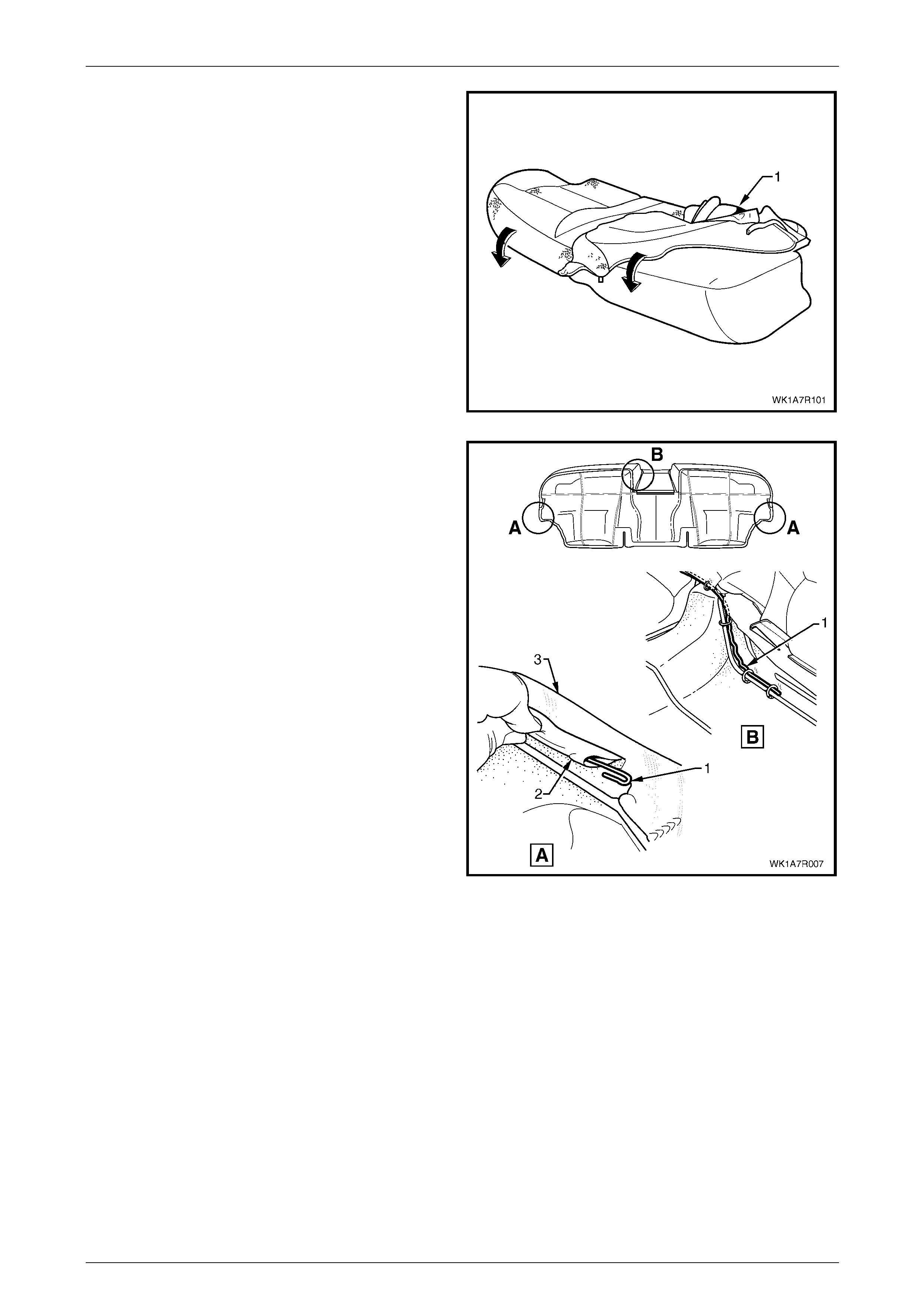
Seat Assemblies Page 1A7A–278
Page 1A7A–278
9 Fold the rear seat cushion cover (1) over the corners
of the cushion ensuring the cushion cover is fitted
neatly into all corners and contours of the rear seat
cushion.
Figure 1A7A – 173
10 If removed, reinstall the retaining wire (1) from the
casing (2) attached to the cushion cover assembly (3).
NOTE
The rear seat Type 3 retaining wire is in two
pieces with the break in the wire across the front
of the seat above the transmission tunnel.
11 Refit the rear seat cushion frame, refer to
Rear Seat Cushion Frame.
Figure 1A7A – 174
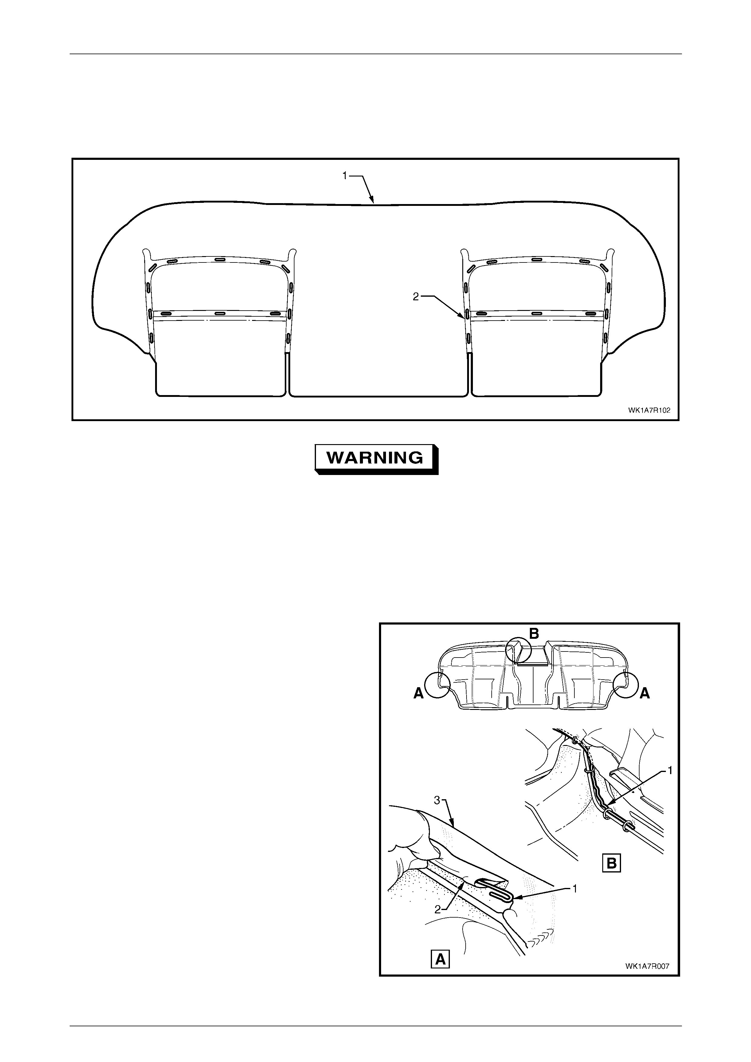
Seat Assemblies Page 1A7A–279
Page 1A7A–279
Rear Seat Type 4
Remove
The rear seat cushion cover (1) for rear seat Type 4 is attached to the cushion with approximately 28 hog rings (2) in the
locations shown, refer to Figure 1A7A – 175.
Figure 1A7A – 175
Safety glasses an d work glo ves must be w orn
at all times when removing the hog rings.
NOTE
Care must be taken when removing the hog rings
not to damage the cushion cover. All hog rings
will be destroyed during this operation and must
be replaced.
Using the following sequence of operations, cut all hog rings as the y are revealed using bolt cutters or side cutters.
1 If required, remove the rear seat cushion frame, refer to Rear Seat Cushion Frame.
2 If required, remove the retaining wire (1) from the
casing (2) attached to the cushion cover assembly (3).
NOTE
The rear seat Type 4 retaining wire is in two
pieces with the break in the wire across the front
of the seat above the transmission tunnel cut-
out.
Figure 1A7A – 176
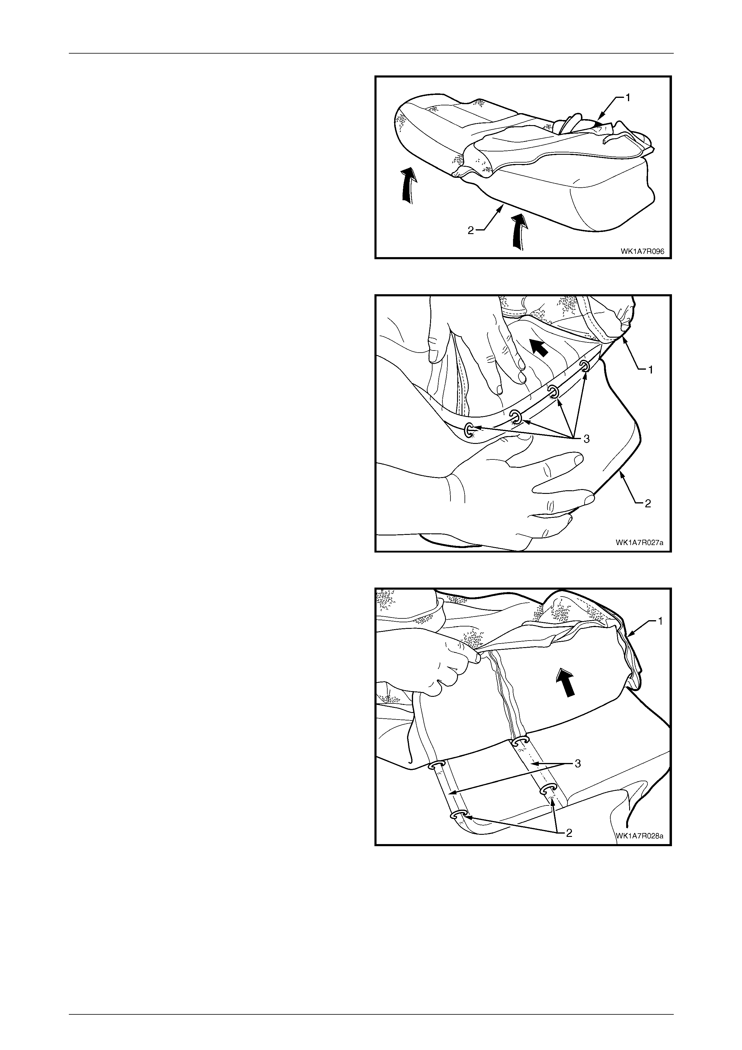
Seat Assemblies Page 1A7A–280
Page 1A7A–280
3 Fold the rear corner of the rear seat cushion cover (1),
up over the rear seat cushion pad (2) then, fold the
front corner of the cover up.
Figure 1A7A – 177
4 Fold the cushion cover (1) back towards the centre of
the seat cushion while holding the cushion pad (2) to
reveal the four hog rings (3) and cut to remove.
Figure 1A7A – 178
5 Continue working towards the centre of the seat
cushion, carefully fold back the cover (1) revealing two
outer hog rings (2), cut these and continue folding the
cover back until all hog rings in each corresponding
groove (3) have been removed.
Figure 1A7A – 179
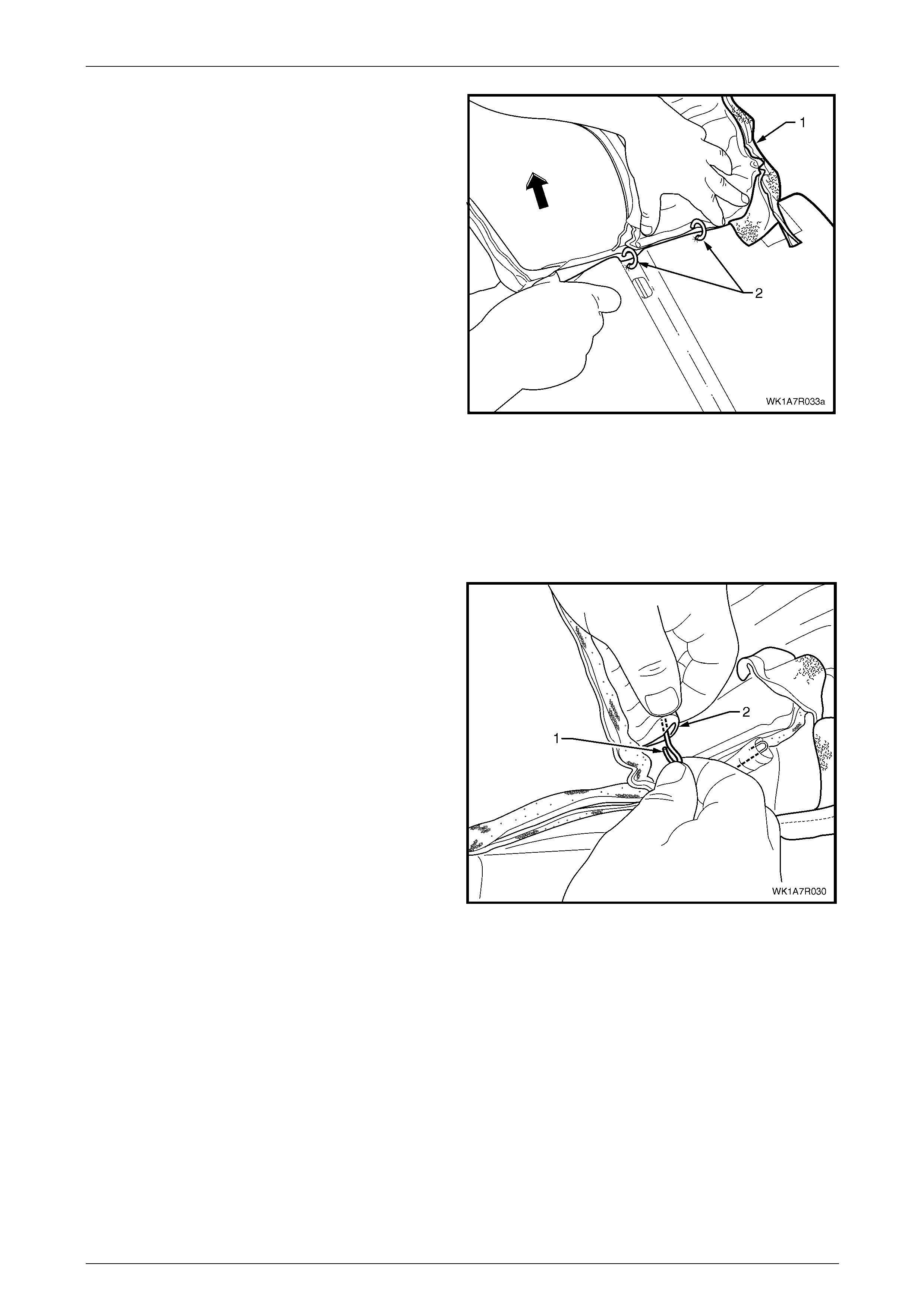
Seat Assemblies Page 1A7A–281
Page 1A7A–281
6 Fold the cushion (1) over towards the centre and from
the front of the seat cushion, cut the hog rings (2), four
places.
7 Repeat steps 3 to 6 for the other side of the rear seat
cushion and remove the cushion cover from the
cushion.
Figure 1A7A – 180
NOTE
The cushion cover has eight retaining wires that
align to the grooves in the cushion pad and are
used to hook the hog rings to. These will need to
be removed from the cover if it is to be replaced.
8 If required, remove the retaining wire (1) from the
casing (2) and repeat for the remaining seve n places.
Figure 1A7A – 181
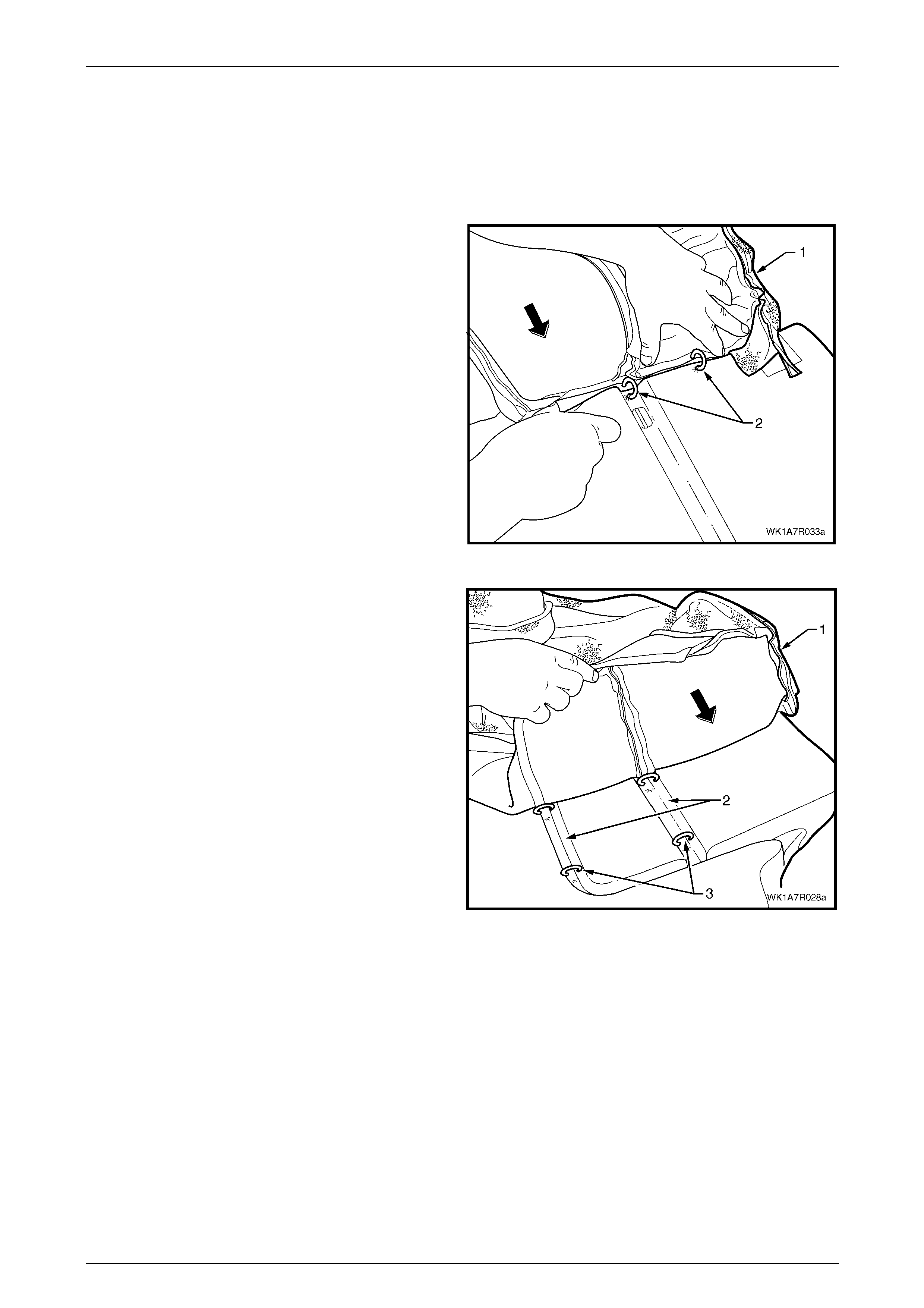
Seat Assemblies Page 1A7A–282
Page 1A7A–282
Reinstall
Referring to Figure 1A7A – 175 showing the hog ring locations, install the rear seat cushion cover using the following
sequence of operations, attachin g the hog rings with hog ring pliers.
If required, reinstall the retaining wire (1) into the casing (2) in eight locations in the cushion cover assembl y, refer to
Figure 1A7A – 181.
1 Beginning on one side of the cushion, position the
cover (1) into the inner corresponding groove. Starting
at the rear and working towards the front, attach the
cushion cover to the cushion pad with hog rings (2),
four places, using hog ring pliers.
NOTE
Ensure the cushion cover aligns to all the
grooves in the cushion pad before attaching the
cover with hog rings.
Figure 1A7A – 182
2 Working outward, position the cushio n cover (1), into
the corresponding grooves (2) and attach with hog
rings (3).
Figure 1A7A – 183

Seat Assemblies Page 1A7A–283
Page 1A7A–283
3 Working along the outside edge of the rear seat
cushion, position the cover (1) into the outer
corresponding groove (2) an d attach with four hog
rings (3).
4 Repeat the process for the opposite side of the rear
seat cushion cover.
Figure 1A7A – 184
5 Fold the rear seat cushion cover (1) over the corners
of the cushion pad (2), ensuri ng that the cushion cover
is fitted neatly into all corners and contours of the rear
seat cushion.
NOTE
As part of their designed appearance, Leather
cushion covers have inherent minor creases in
the material.
Figure 1A7A – 185
6 If removed, reinstall the retaining wire (1) from the
casing (2) attached to the cushion cover assembly (3).
NOTE
The rear seat Type 4 retaining wire is in two
pieces with the break in the wire across the front
of the seat above the transmission tunnel.
7 Refit the rear seat cushion frame, refer to
Rear Seat Cushion Frame.
Figure 1A7A – 186

Seat Assemblies Page 1A7A–284
Page 1A7A–284
Rear Seat Type 5
Surebond cushion cover and pad assembly are glued together as an assembly and are not serviced as separate
components. If either the pad or the cover requir es replacement, both will have to be replaced as a combined unit.
Rear Seat Type 8
Remove
1 If required, remove the rear seat cushion frame, refer to Rear Seat Cushion Frame.
2 If required, the retaining wire (1) from the casing (2)
attached to the rear seat cushion cover assembly (3).
Figure 1A7A – 187
3 Fold the rear corner of the rear seat cushion cover (1)
over the rear seat cushion pad (2).
Figure 1A7A – 188
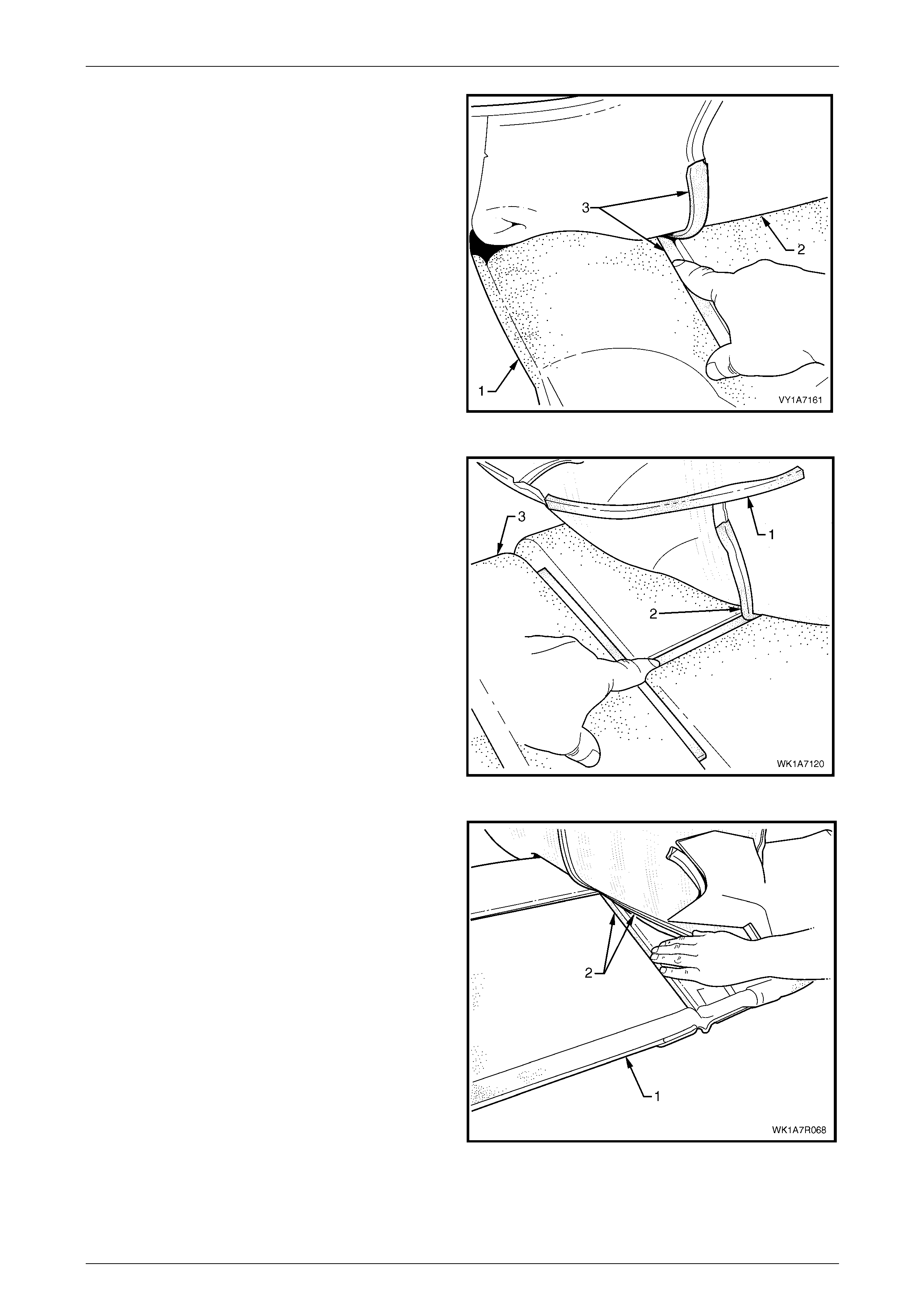
Seat Assemblies Page 1A7A–285
Page 1A7A–285
4 While holding the rear seat cushion pad (1), pull the
rear corner of the seat cushion cover (2) away from
the rear seat cushion pad to disenga ge the hook and
loop strip (3).
Figure 1A7A – 189
5 After disengaging the outer hook and l oop strip (1),
disengage the cross hook and loop strip (2) while
holding the seat cushion pad (3).
Figure 1A7A – 190
6 While holding the rear seat cushion pad (1),
disengage the inner hook and loop strip (2).
7 Repeat steps 3 to 6 for the opposite half of the rear
seat cushion assembly.
8 Remove the rear seat cushion cover.
Figure 1A7A – 191
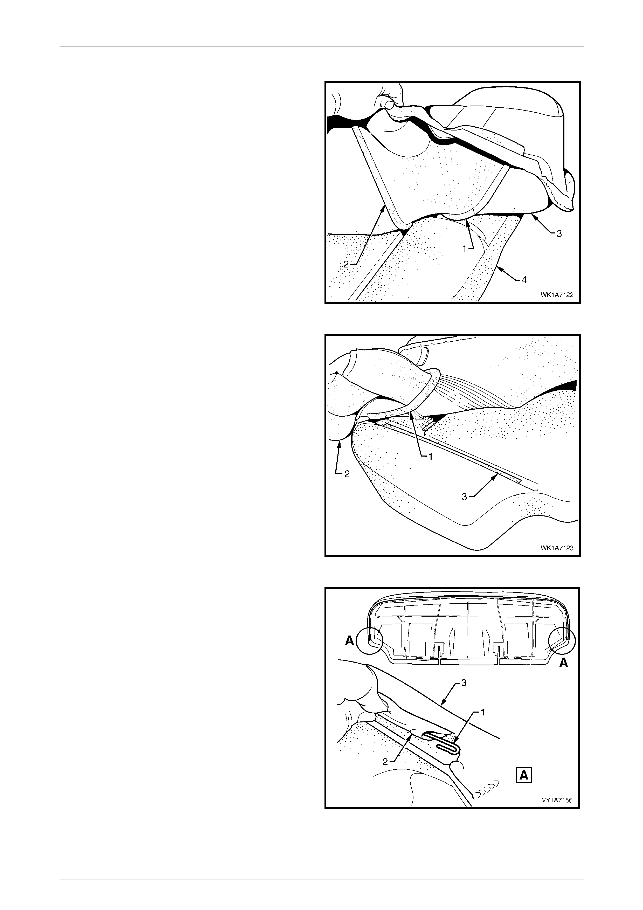
Seat Assemblies Page 1A7A–286
Page 1A7A–286
Reinstall
1 Align the inner hook and l oop strip (1) and the cross
hook and loop strip (2), on the seat cushion cover (3)
with the seat cushion pad (4).
2 Press the folded edge of the rear seat cushion cover
firmly into the corresponding groove in the seat
cushion pad to engage the hook and loop strip.
Figure 1A7A – 192
3 Align and press the outer hook and loop strip (1), on
the seat cushion cover (2), with the corresponding
groove in the seat cushion pad (3).
4 Repeat this process for the opposite half of the rear
seat cover and pad, starting with the inner strip.
Figure 1A7A – 193
5 If removed, reinstall the retaining wire (1) from the
casing (2) attached to the cushion cover assembly (3).
Figure 1A7A – 194
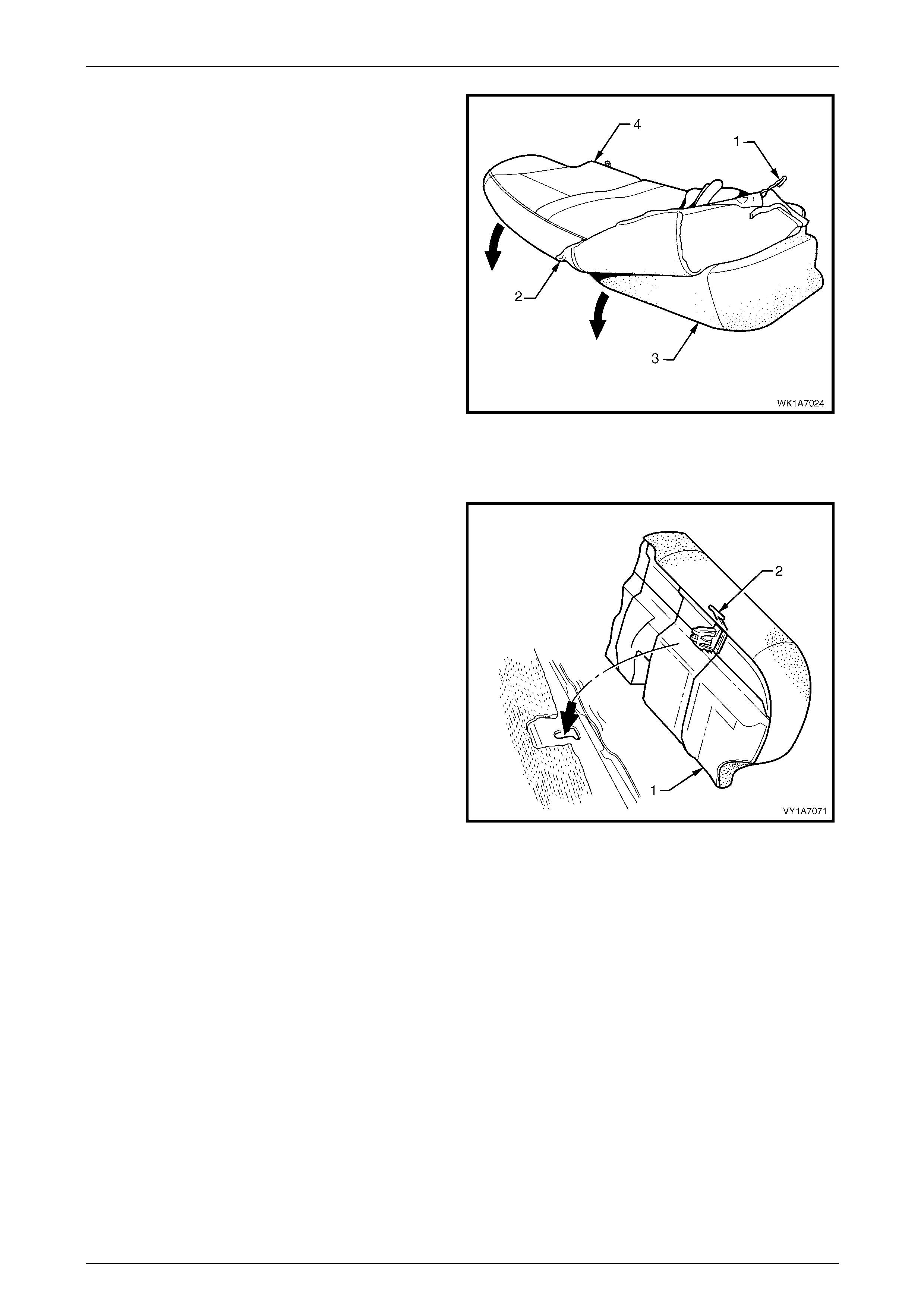
Seat Assemblies Page 1A7A–287
Page 1A7A–287
6 With the retaining wire (1) fitted to the rear seat
cushion cover (2), roll the front corner of the cover
over the seat cushion pad (3).
7 Roll the sides of the seat cushion cover over the seat
cushion pad.
8 Roll the rear corners (4) of the seat cushion cover over
the seat cushion pad.
NOTE
Ensure the pad is fitted neatly by hand into all
corners and contours of the seat cover.
9 Refit the rear seat cushion frame, refer to
Rear Seat Cushion Frame.
Figure 1A7A – 195
Reinstall
1 Sit the rear seat cushion assembly into positi on.
2 Push the rear seat cushion assembly (1) into the
seat-back and push the front of the cushion assembly
down until the locking mechanisms (2) lock into
position.
Figure 1A7A – 196
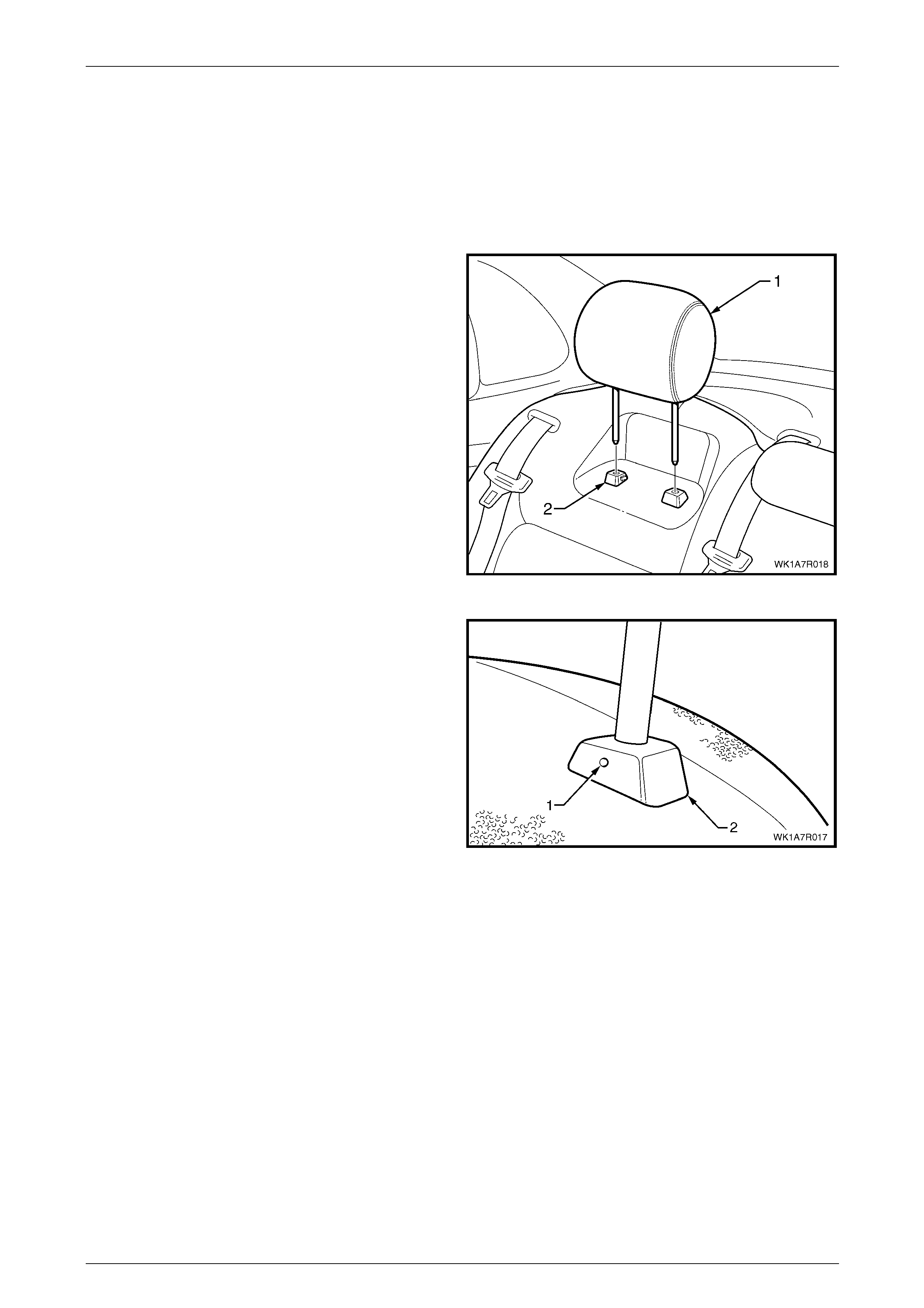
Seat Assemblies Page 1A7A–288
Page 1A7A–288
6.3 Rear Seat-back Head Restraint Assembly
Right-hand and Left-hand Side
LT Section No. – 14-350
Remove
1 Raise the rear seat-back head restraint assembl y (1)
to the first stop position.
2 Depress the head restraint sleeve height adjuster
lock (2) and raise the head restraint to the upper stop
position.
Figure 1A7A – 197
3 Manufacture a suitable size probe and insert into the
hole (1) in the inboard head restraint sleeve (2).
4 Push the probe in slightly whil e applying slight upward
pressure on the headrest and remove the head
restraint completely out of the sleeve.
Figure 1A7A – 198
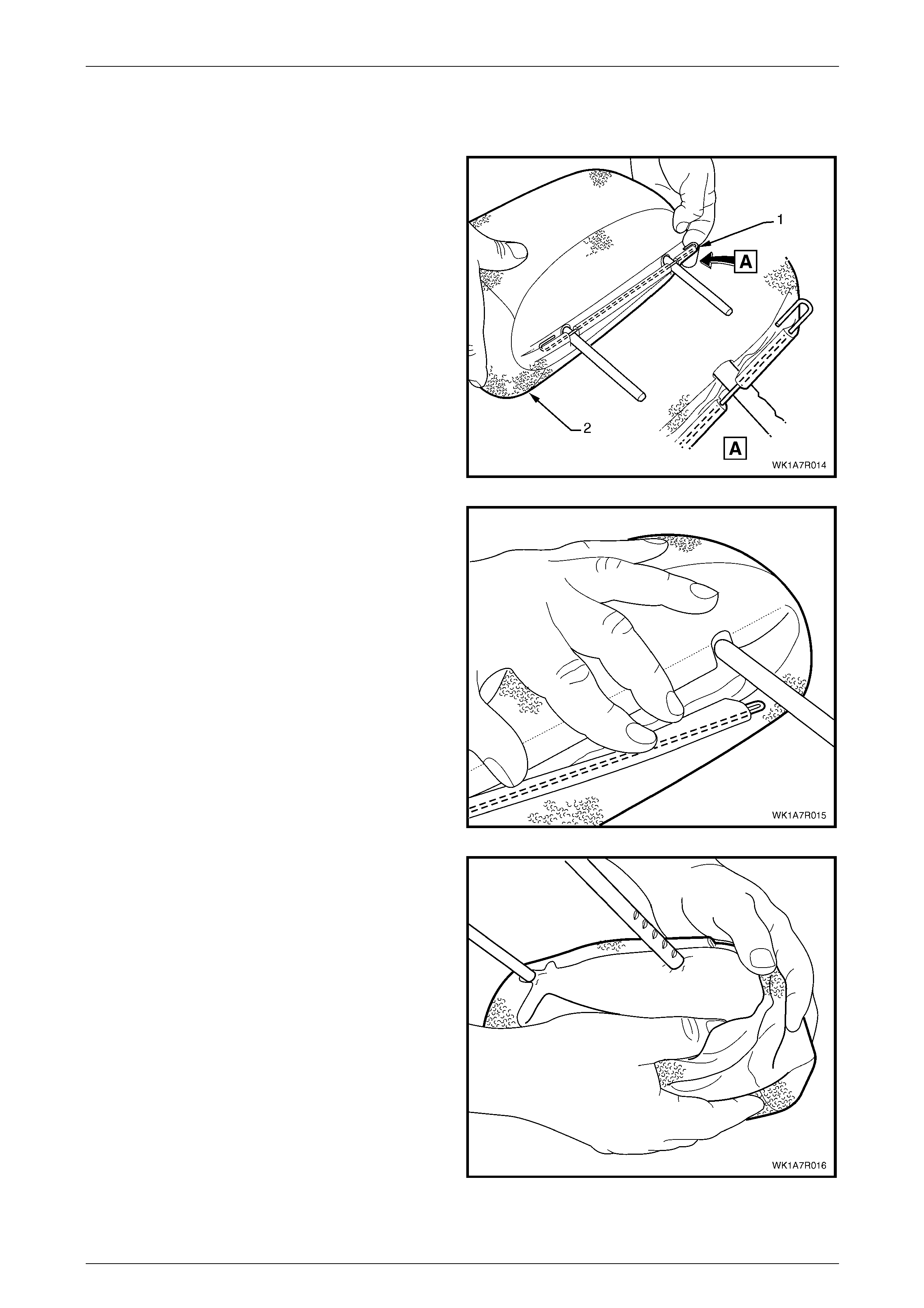
Seat Assemblies Page 1A7A–289
Page 1A7A–289
Except Rear Seat Type 8 Head Restraint
Disassemble
1 Unhook the wire retainer (1) from the head restraint
cover (2).
Figure 1A7A – 199
2 Carefully pull the wire retainer through the head
restraint cover and remove.
3 Repeat the process for the remaining wire retainer.
Figure 1A7A – 200
4 Starting at one end, gently pull the hea d restraint
cover back over the head restraint pad and remove.
Figure 1A7A – 201
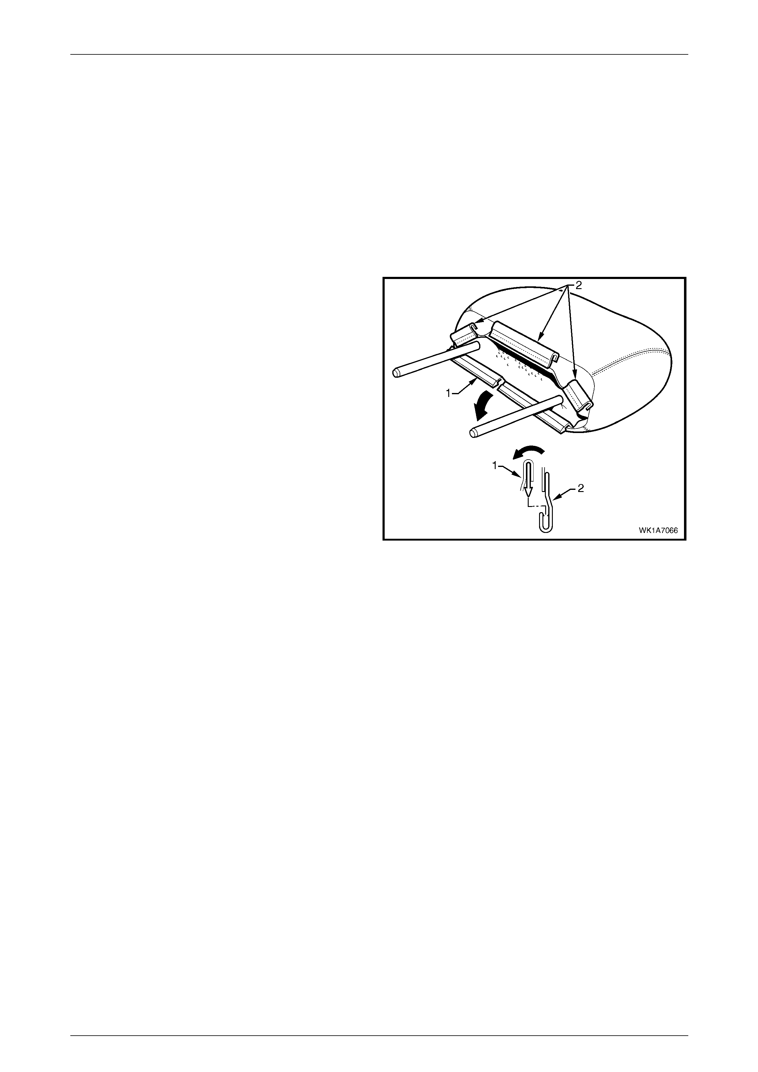
Seat Assemblies Page 1A7A–290
Page 1A7A–290
Reassemble
Reassembly of the rear seat-back head restraint assembly is the reverse of the removal procedure, noting the following:
1 Align the cover to the head restraint pad taking note of the contour of both the cover and the pad.
2 Position the head restraint pad inner liner so that it covers the pad.
3 Both loops on the wire retaine r are hooked into the rear seat-back head restraint cover.
4 Ensure the cover is fitted neatly to the head restraint pad and has no creases.
Rear Seat Type 8 Head Restraint
Disassemble
1 Disengage the front head restraint cover J-stri p by
pulling the flap (1) back and out of flap (2) in the
direction shown.
2 Beginning at one corner of the head restraint, gently
remove the cover from the pad assembly.
Figure 1A7A – 202
Reassemble
Reassembly of the rear seat-back head restraint assembly is the reverse of the removal procedure. Ensure the head
restraint cover J-strip is fully engaged and th e cover is fitted neatly with no creases.
Reinstall
Position the head restraint in the sleeves and push down firmly.

Seat Assemblies Page 1A7A–291
Page 1A7A–291
6.4 Rear Seat-back Assembly
LT Section No. – 14-325
Remove
1 If required, remove the following:
a Remove the rear seat cushion assembly, refer to 6.2 Rear Seat Cushion Assembly.
b Remove the lower seatbelt anchor bolt, refer to Section 12M, 2.2 Rear Seatbelt Assembly – Outboard.
2 Remove the bolt (1), retaining the rear seat-back
assembly (2) to the vehicle.
3 Lift the rear seat-back assembly up and out of the t wo
retaining brackets (3).
Figure 1A7A – 203
4 Insert a suitable screwdriver (1) into the seatbelt
escutcheon (2) and while applying a slight upwar d
pressure, push the retaining clip in to rel ease the
escutcheon.
5 Remove the seat belt and escutcheon from the rear
seat-back assembly by feedin g it through the opening
in the rear seat-back assembly.
6 Remove the rear seat-back assembly and repeat for
the opposite side if required.
Figure 1A7A – 204
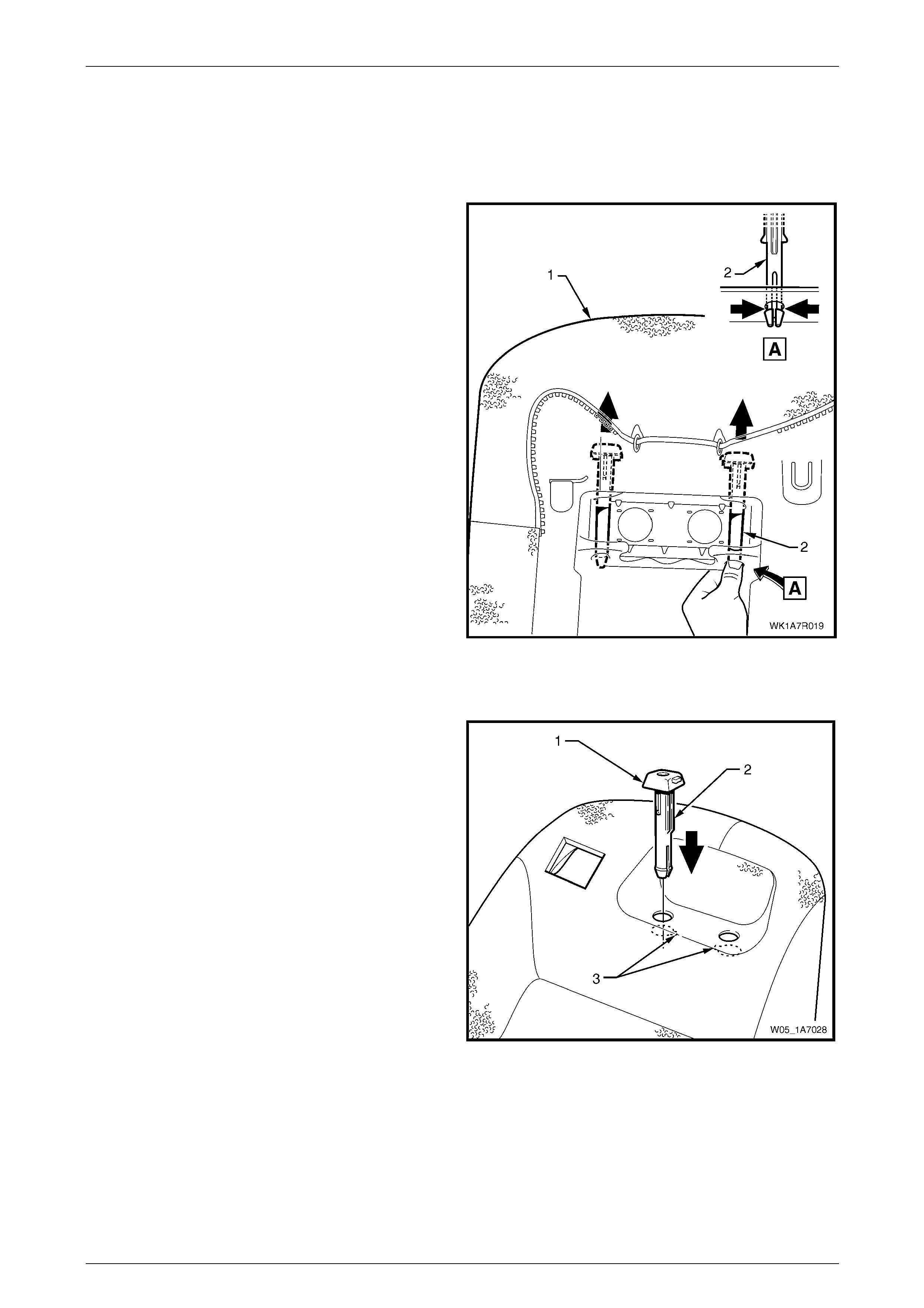
Seat Assemblies Page 1A7A–292
Page 1A7A–292
Head Restraint Sleeve
Remove
If required, remove the rear seat-back head r estraint,
refer to 6.3 Rear Seat-back Head Restraint Assembly Right-hand and Left-hand Side.
1 From the back of rear seat-back (1) (foam side),
squeeze the head restraint sleeve locating prongs (2)
together and remove the sleeve up and out of the
seat-back assembly.
2 Repeat this process for the remaining head restraint
sleeve.
Figure 1A7A – 205
Reinstall
Reinstallation of the rear seat head restraint sleeve is the
reverse of the removal procedure ens uring the locating ribs
(2) of the head restraint sleeve (1) aligns with the key-way
(3) in the seat-back frame.
NOTE
The release button in the right-hand sleeve and
the hole in the left-hand side sleeve should face
each other when installed corr ectly.
Figure 1A7A – 206
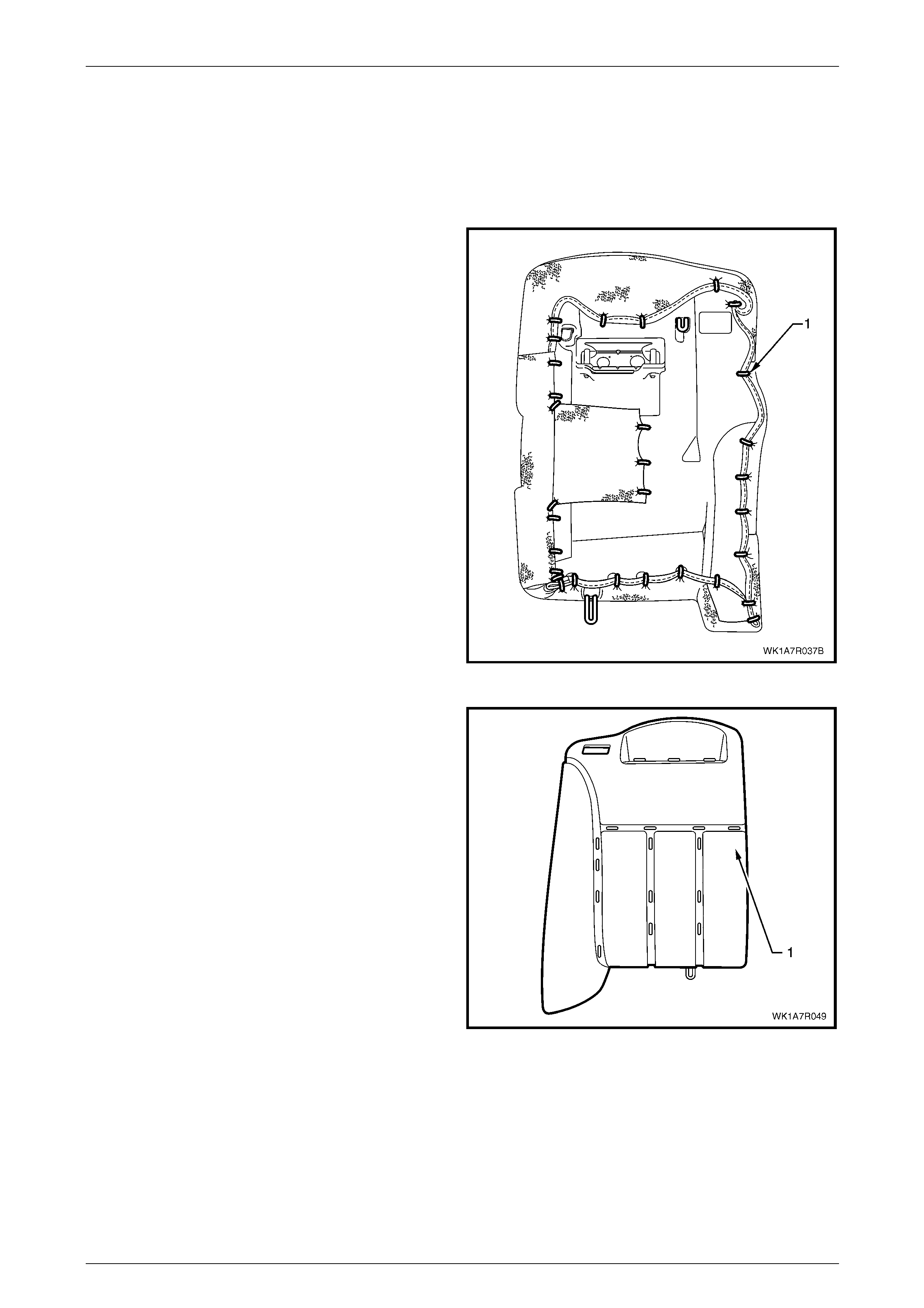
Seat Assemblies Page 1A7A–293
Page 1A7A–293
Rear Seat-back Cover
Rear Seat Type 1 and 6
Remove
1 Place the rear seat-back assembly face down.
2 Using bolt cutters or side cutters, remove
approximately 31 hog rings (1) attaching the cover to
the outer sections of the rear seat-back pad and frame
assembly in the locations shown.
NOTE
Care must be taken when removing the hog
rings, not to damage the rear seat-back cover.
All hog rings will be damaged in this operation
and will require replacement.
NOTE
The rear seat Type 1, right-hand side rear
seat-back assembly is fitted with a first aid kit
pouch. For rear seat Type 6, the hog rings used
to attach the first aid kit pouch are installed along
the inner edge of the rear seat-back cushio n and
frame assembly.
Figure 1A7A – 207
3 Using the following sequence of operations continue
and cut the hog rings as they are revealed us ing bolt
cutters or side cutters at the locations shown.
Figure 1A7A – 208
4 Remove the head restraint sleeve, refer to Head Restraint Sleeve.

Seat Assemblies Page 1A7A–294
Page 1A7A–294
5 Fold the upper portion of the rear seat-back cover (1)
over the rear seat-back pad assembly (2).
6 Remove the head restraint retaining wire (3) by cutting
the three hog rings (4).
Figure 1A7A – 209
7 While holding the rear seat-back pad assembly (1),
pull the outer edge of the cover (2) away from the rear
seat-back pad and cut the four hog rings (3) along the
outer groove.
Figure 1A7A – 210
8 While holding the seat-back pad assembly (1), fold the
top edge of the cover (2) over the top of the seat-back
assembly to reveal the four hog rings (3) in the upper
horizontal groove of the pad and cut to remove.
Figure 1A7A – 211
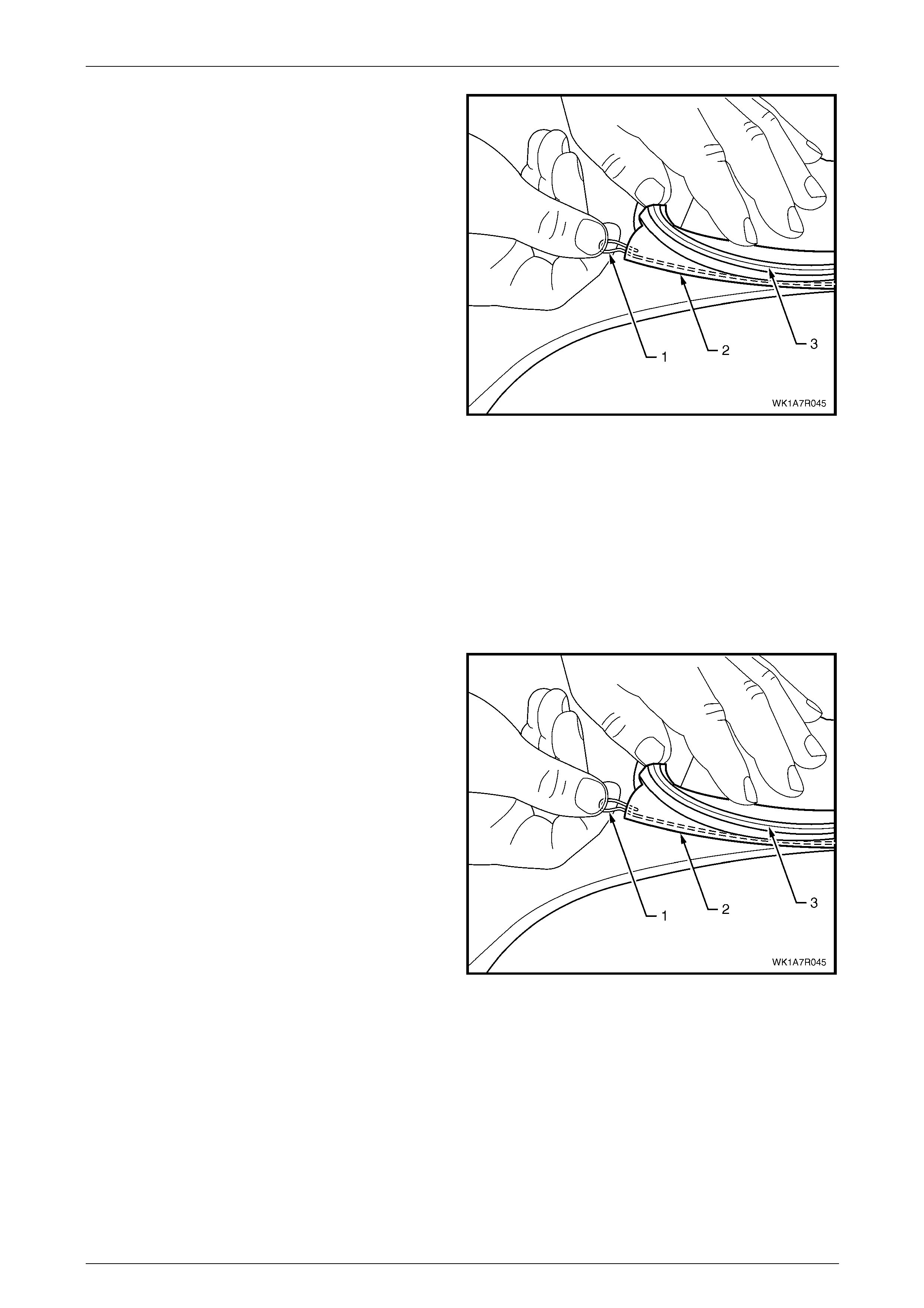
Seat Assemblies Page 1A7A–295
Page 1A7A–295
9 Remove the retaining wire (1) for the upper horizontal
groove from the casing (2) attached to the cover (3).
10 Continue to fold the cover towards the centre of the
pad and cut the three hog rings from the centre
corresponding groove.
11 If required, remove the retaining wire from the casing
attached to the cover as in step 6.
12 Repeat the process for the remaining thre e hog rings
and retaining wire in the inner corresp onding groove.
13 Remove the rear seat-back cover.
Figure 1A7A – 212
Reinstall
Using the following sequence of operations, align the rear seat-back cov er to the pad assembly (1) and attach with
approximately 17 hog rings in the positions shown, refer to Figure 1A7A – 208.
NOTE
Ensure that the seat-back cover aligns with all
grooves in the pad before attaching with hog
rings.
1 If removed, reinstall the retaining wire (1) into the inn er
groove casing (2) attached to the cover (3).
Figure 1A7A – 213
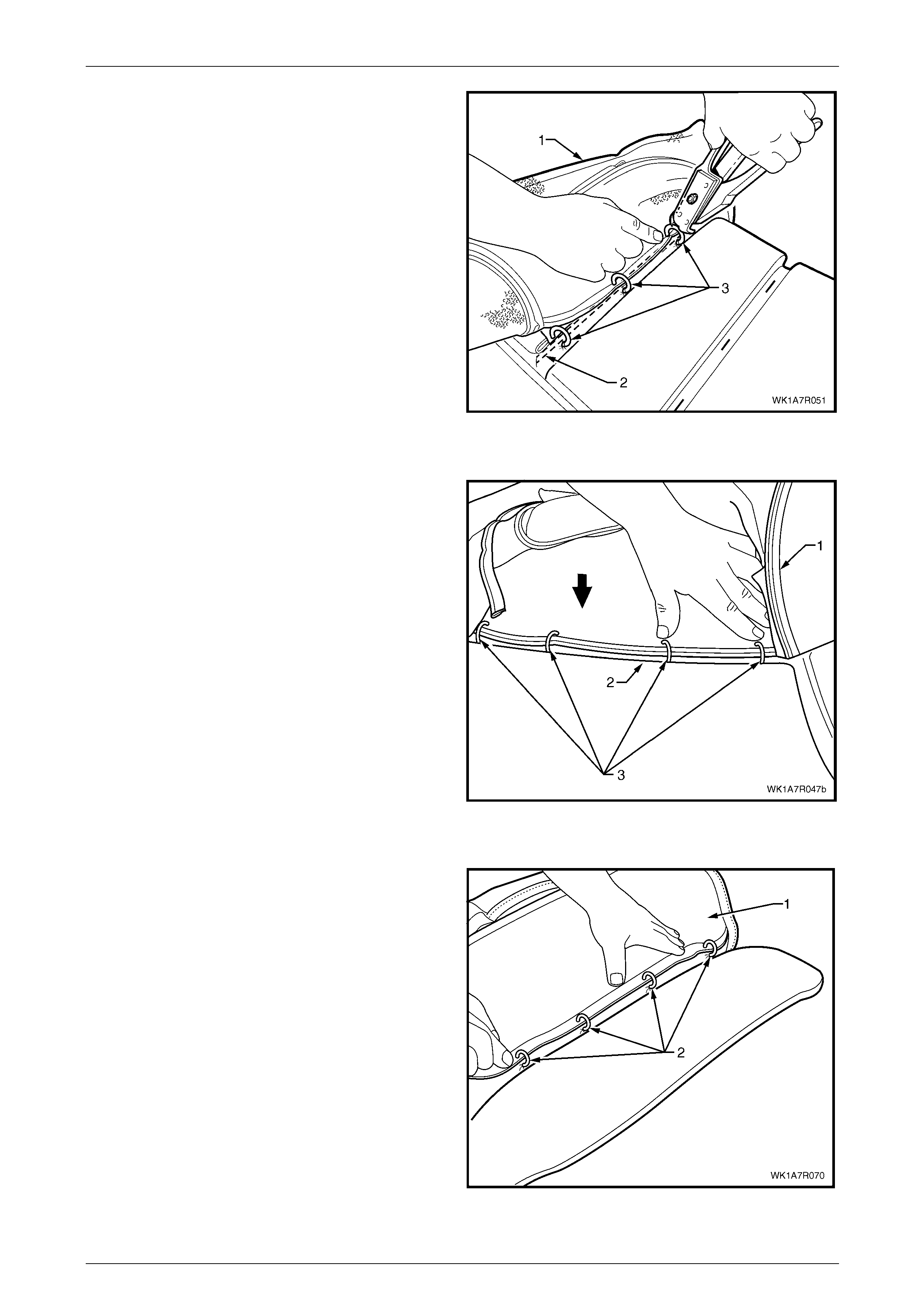
Seat Assemblies Page 1A7A–296
Page 1A7A–296
2 Align the cover (1) to the inner vertical corresponding
groove in the pad (2) and attach with three hog rings
(3), using hog ring pliers.
3 Repeat steps 1 and 2 for the centre vertical
corresponding groove.
Figure 1A7A – 214
4 If removed, reinstall the retaining wire (1) into the up per horizontal groove casing (2) attached to the cov er (3), refer
to Figure 1A7A – 213.
5 Align the cover (1) to the upper horizontal groove (2)
and attach with four hog rings (3).
Figure 1A7A – 215
6 If removed, reinstall the retaining wire (1) into the outer groove casing (2) attached to the cover (3), refer to
Figure 1A7A – 213.
7 Align the cover (1) to the outer vertical groov e in the
pad and attach with four hog rings (2).
Figure 1A7A – 216
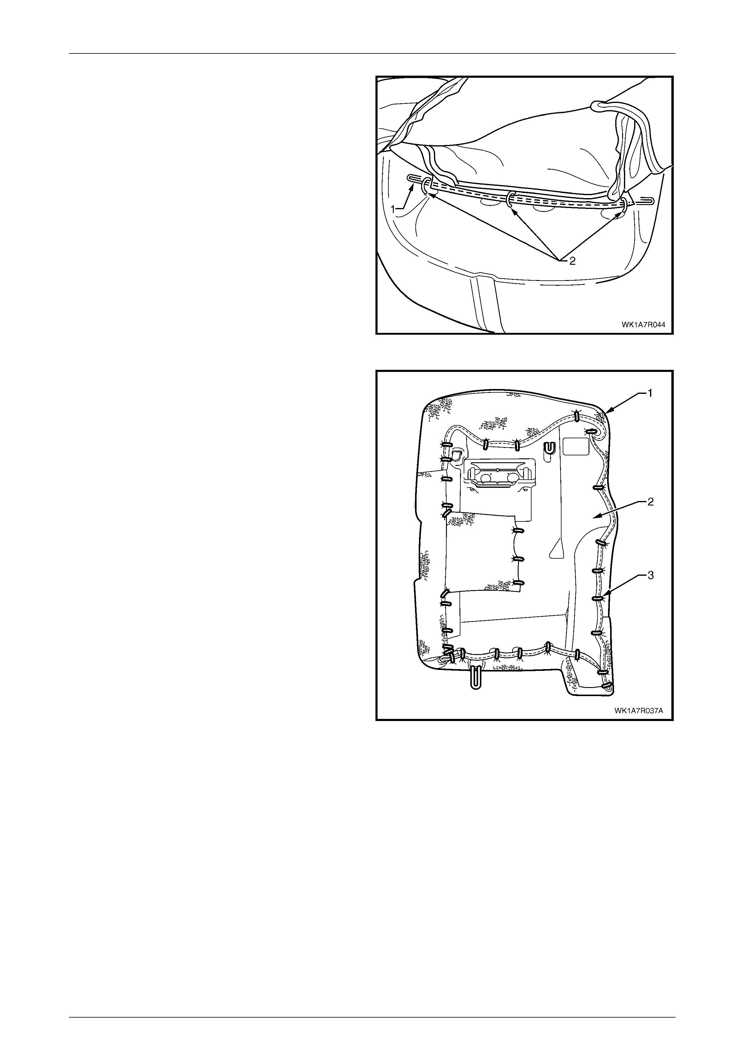
Seat Assemblies Page 1A7A–297
Page 1A7A–297
8 Attach the restraint retaining wire (1) with three hog
rings (2) to the frame.
Figure 1A7A – 217
9 Place the seat-back assembly face down on a clean
surface and using the following sequence of
operations, continue attaching the rear seat-back
cover (1) to the pad assembly (2) with hog rings (3),
approximately 31 places, in the positi ons shown.
Figure 1A7A – 218
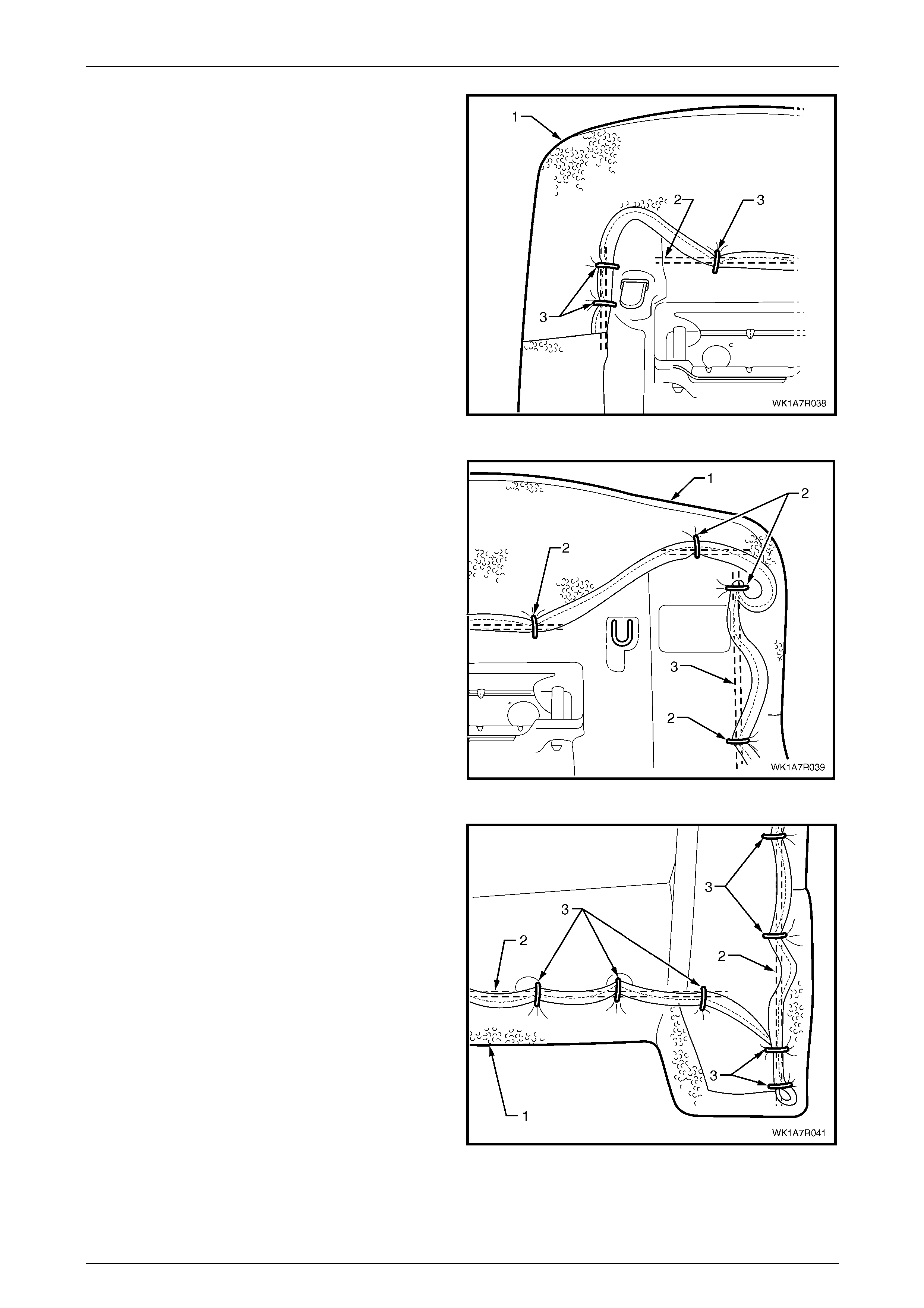
Seat Assemblies Page 1A7A–298
Page 1A7A–298
10 Starting at the upper inner corner of the rear
seat-back, pull the cover (1) over the corner and
attach to the wire frame (2) with three hog rings (3).
Figure 1A7A – 219
11 While pulling the outboard side corner of the cover (1)
over the top and towards the centre, fix with four hog
rings (2) to the wire frame (3).
Figure 1A7A – 220
12 Continue at the outboard lower corner and attach the
cover (1) to the frame (2), by pulling the cover tight
and fixing with seven hog ri ngs (3).
Figure 1A7A – 221
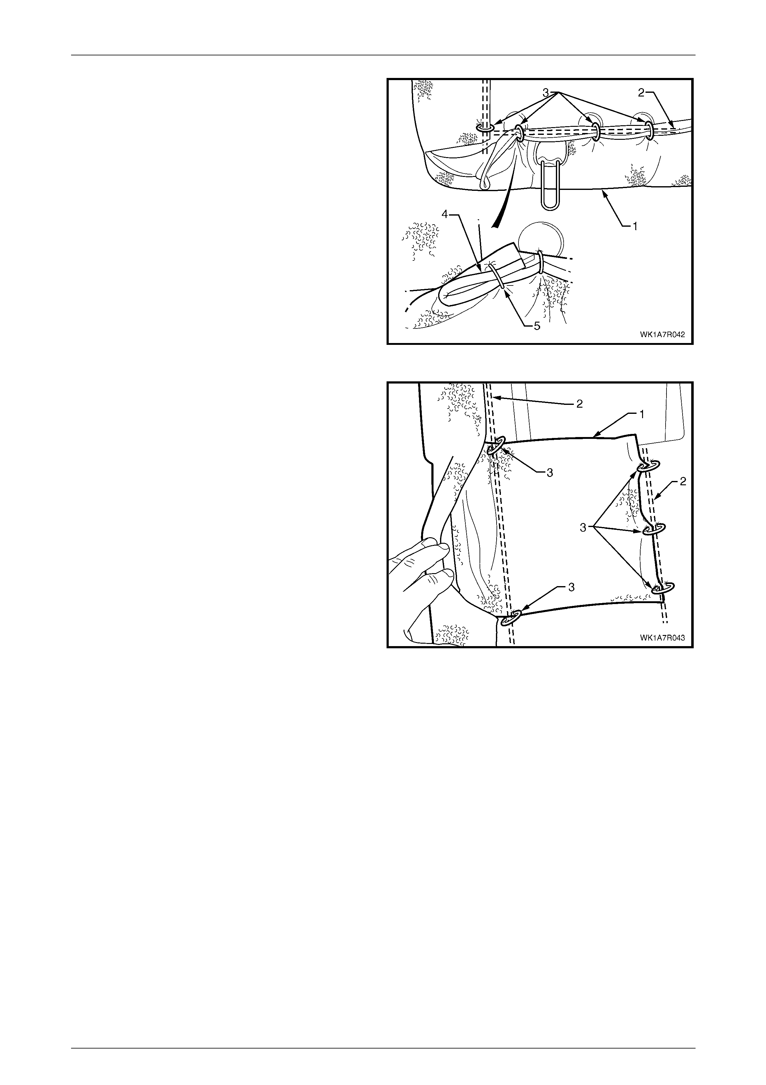
Seat Assemblies Page 1A7A–299
Page 1A7A–299
13 Continue at the inner lower corner and attach the
cover (1) to the frame (2), by pulling the cover tight
and fixing with four hog rings (3).
14 Attach the seat-back cover lower pi ping overhang (4)
with one hog ring (5) back on to the lower piping.
Figure 1A7A – 222
15 If fitted with a first aid kit pouch (1) attach the pouch to
the frame (2) with five hog rings (3).
NOTE
The rear seat Type 1, right-hand side rear
seat-back assembly is fitted with a first aid kit
pouch. For rear seat Type 6 rear seat-back
assembly, the hog rings used to attach the first
aid kit pouch are installed along the inner edge
of the rear seat-back cushion and frame
assembly.
16 Continue along the inner edge and attach the cover to
the frame, by pulling the cover tight and fixi ng with a
further three hog rings.
NOTE
Ensure the cover is fitted neatly by hand into all
corners and contours of the rear seat-back pad
and is free from any creases. Figure 1A7A – 223
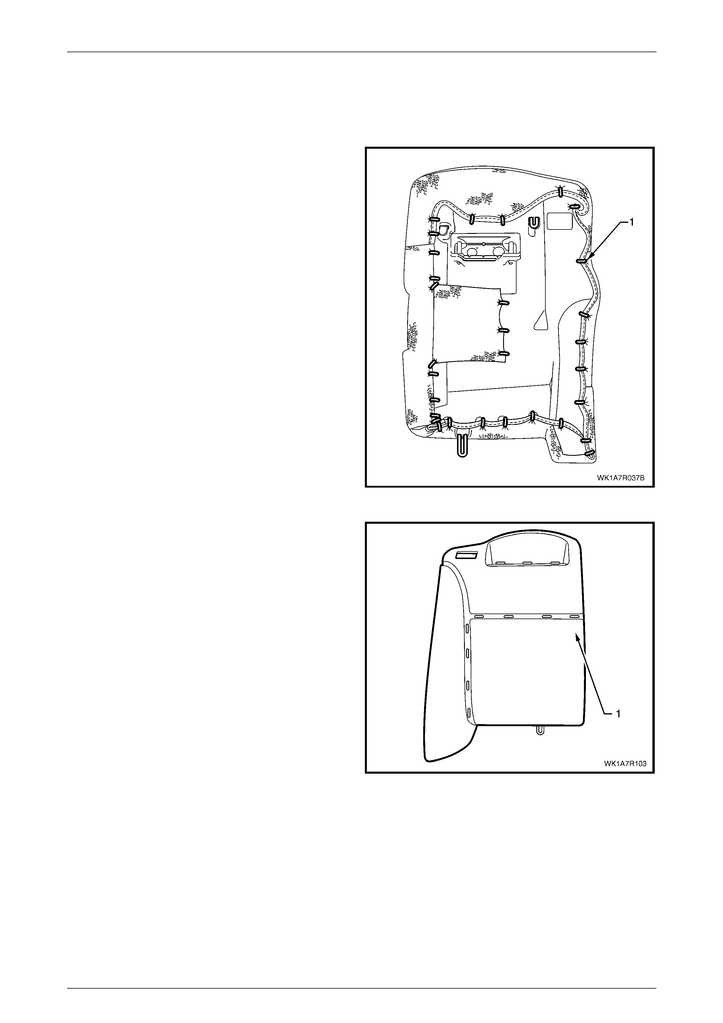
Seat Assemblies Page 1A7A–300
Page 1A7A–300
Rear Seat Type 2 and 7
Remove
1 Place the rear seat-back assembly face down.
2 Using bolt cutters or side cutters, remove
approximately 31 hog rings (1) attaching the outer
sections of the cover to the rear seat-back pad and
frame assembly.
NOTE
Care must be taken when removing the hog
rings, not to damage the rear seat-back cover.
All hog rings will be damaged in this operation
and will require replacement.
NOTE
The rear seat Type 2, right-hand side rear
seat-back assembly is fitted with a first aid kit
pouch. For rear seat Type 7 rear seat-back
assembly, the hog rings used to attach the first
aid kit pouch are installed along the inner edge
of the rear seat-back cushion and frame
assembly.
Figure 1A7A – 224
3 After removing the rear hog rings, continue with the
following sequence of operati ons and cut the hog rings
attaching the cover to the front side of the pad (1), as
they are revealed using bolt cutters or side cutters at
the locations shown.
Figure 1A7A – 225
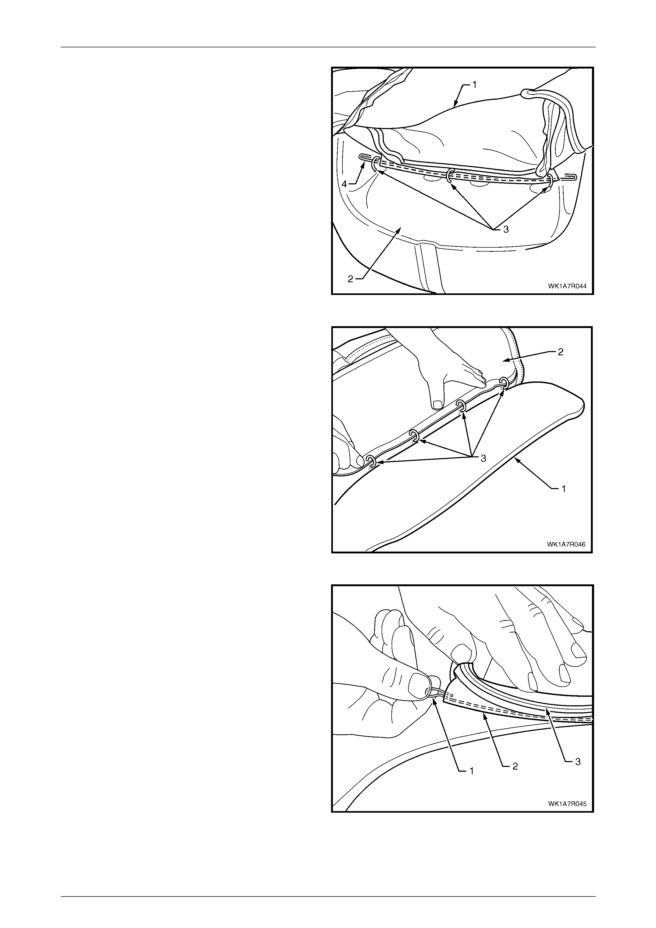
Seat Assemblies Page 1A7A–301
Page 1A7A–301
4 Fold the upper portion of the rear seat-back cover (1)
over the rear seat-back pad assembly (2) and remove
the three hog rings (3) attaching the head restraint
retaining wire (4).
Figure 1A7A – 226
5 While holding the rear seat-back pad assembly (1),
pull the outer edge of the cover (2) away from the rear
seat-back pad and cut the four hog rings (3) along the
outer groove.
Figure 1A7A – 227
6 If required, remove the retaining wire (1) for the outer
groove from the casing (2) attached to the cover (3).
Figure 1A7A – 228
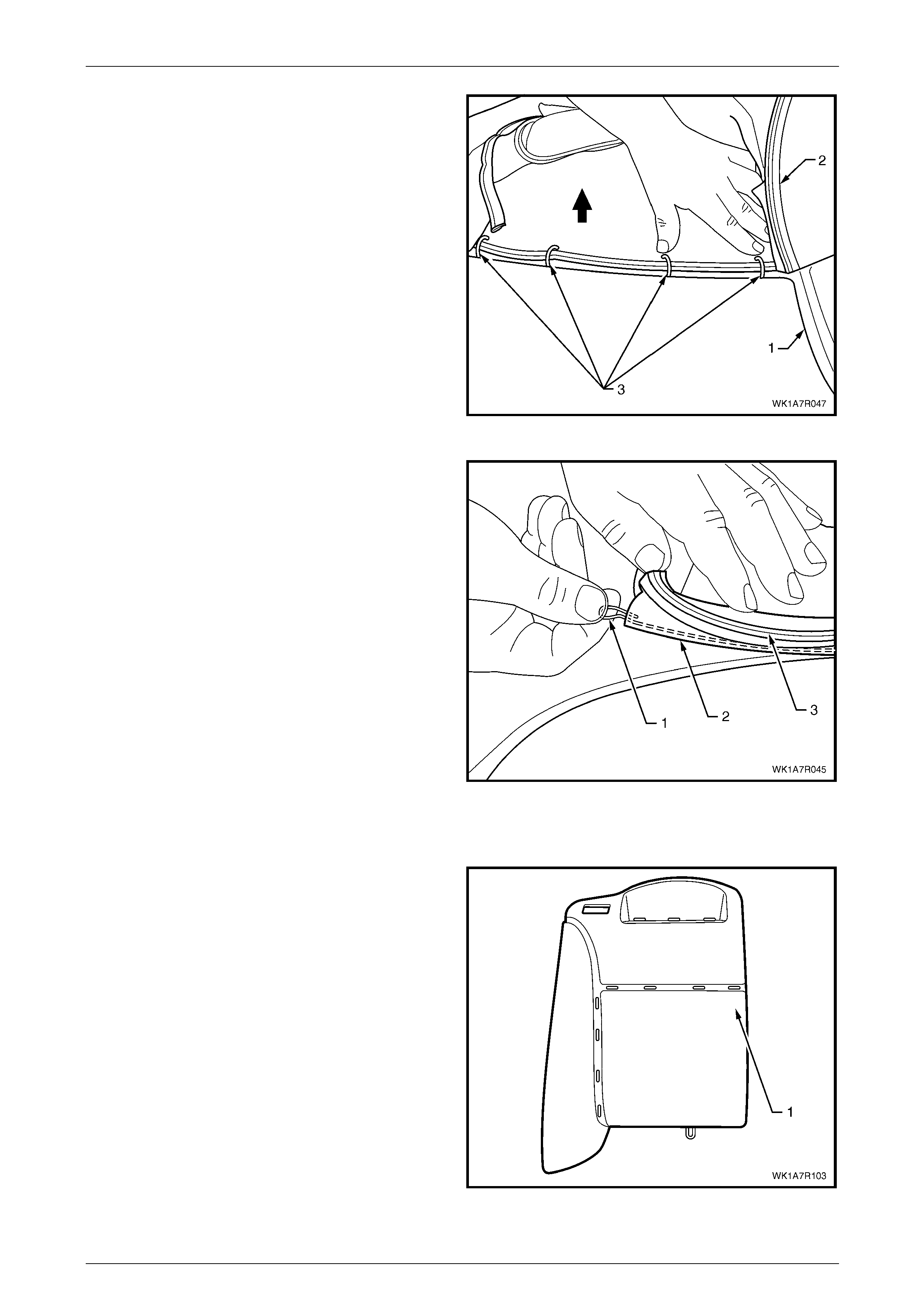
Seat Assemblies Page 1A7A–302
Page 1A7A–302
7 While holding the seat-back pad assembly (1), fold the
top edge of the cover (2) over to reveal the four hog
rings (3) in the upper horizontal groove of the pad and
cut the hog rings to remove.
Figure 1A7A – 229
8 Remove the retaining wire (1) for the upper horizontal
groove from the casing (2) attached to the cover (3)
and remove the rear seat-back cover from the pad
assembly.
Figure 1A7A – 230
Reinstall
1 Using the following sequence of operations, align the
rear seat-back cover to the pad assembly (1) and
attach with approximately eight hog rings in the
positions shown.
NOTE
Ensure that the rear seat-back cover aligns with
the pad at all grooves before attachin g hog rings.
Figure 1A7A – 231

Seat Assemblies Page 1A7A–303
Page 1A7A–303
2 Reinstall the retaining wire (1) into the upper horiz ontal
groove casing (2) attached to the cover (3).
Figure 1A7A – 232
3 Align the cover (1) to the upper horizontal groove (2)
and attach with four hog rings (3).
Figure 1A7A – 233
4 Reinstall the retaining wire (1) into the outer groove
casing (2) attached to the cover (3).
Figure 1A7A – 234
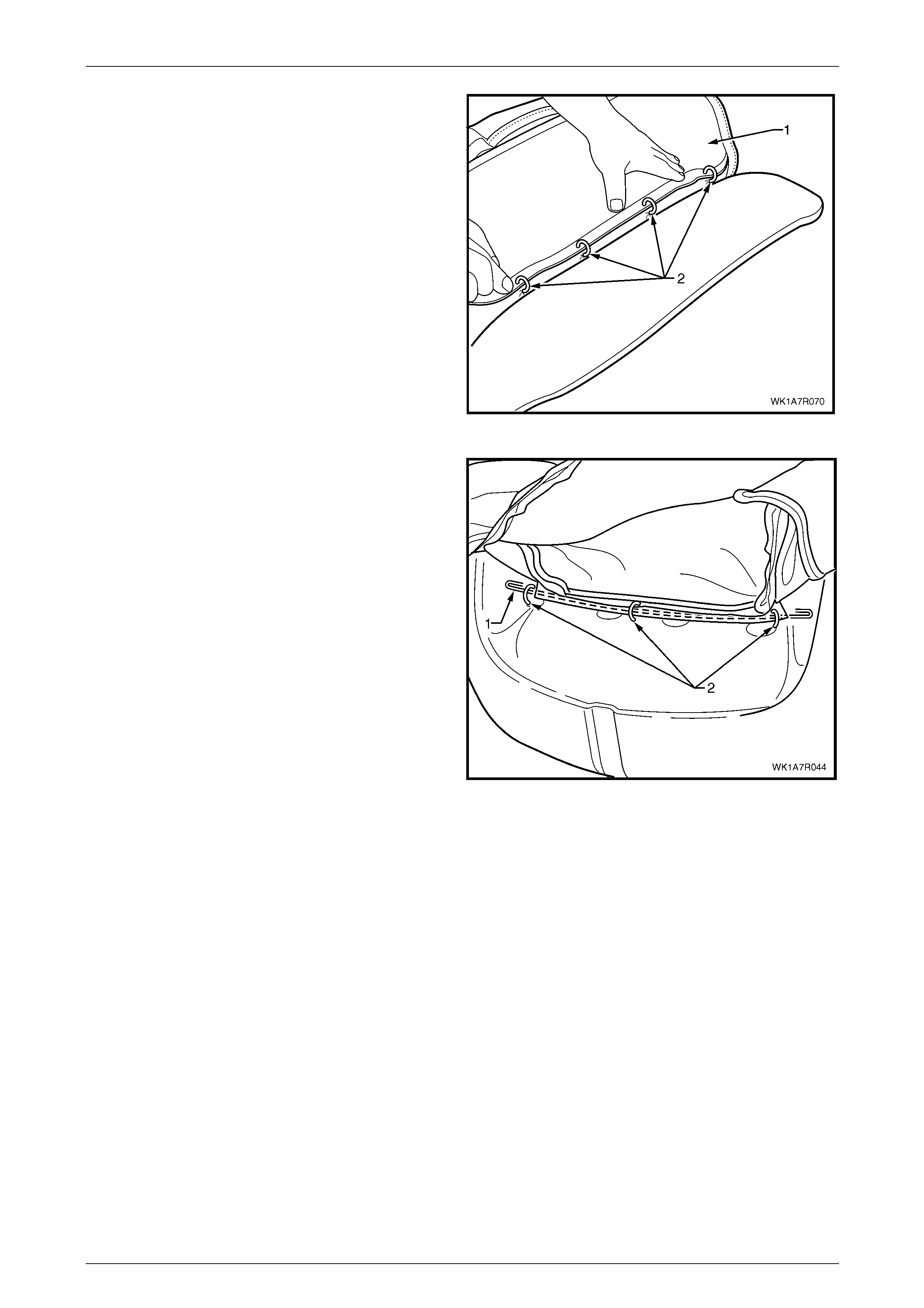
Seat Assemblies Page 1A7A–304
Page 1A7A–304
5 Align the cover (1) to the outboard vertical groove in
the pad and attach with four hog rings (2).
Figure 1A7A – 235
6 Attach the head restraint retaining wire (1) with three
hog rings (2) to the frame.
Figure 1A7A – 236
7 Place the seat-back assembly face down on a clean surface and using the following sequence of operati ons,
continue attaching the rear seat-back cover (1) to the pad assembly (2) with hog rings (3), appro x imately 31 places,
in the positions shown, refer Figure 1A7A – 224.

Seat Assemblies Page 1A7A–305
Page 1A7A–305
8 Starting at the upper inboard corner of the rear
seat-back, pull the cover (1) over the corner and
attach to the wire frame (2) with three hog rings (3).
Figure 1A7A – 237
9 While pulling the outboard side corner of the cover (1)
over the top and towards the centre, fix with four hog
rings (2) to the wire frame (3).
Figure 1A7A – 238
10 Continue at the outboard lower corner and attach the
cover (1) to the frame (2), by pulling the cover tight
and fixing with seven hog ri ngs (3).
Figure 1A7A – 239
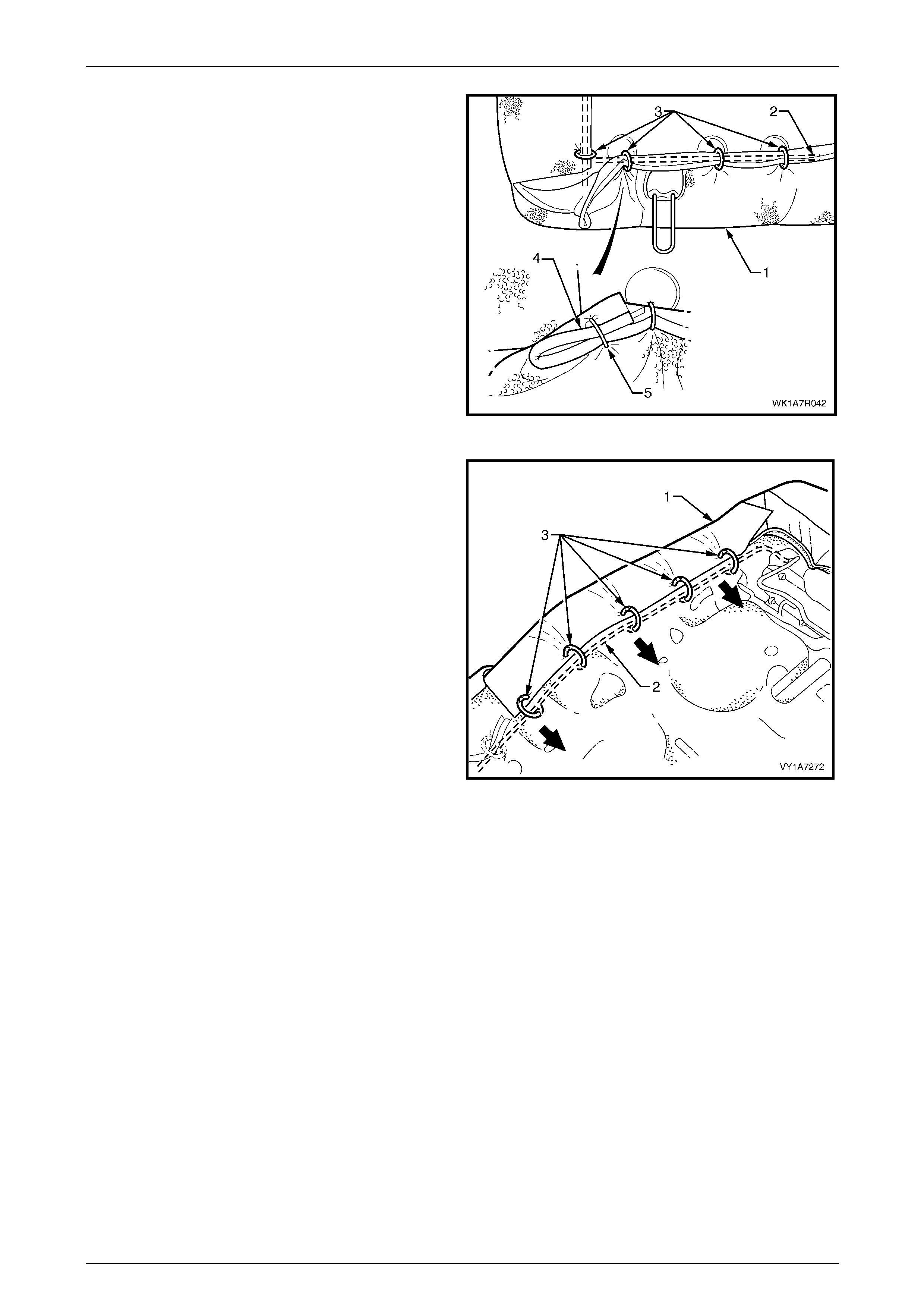
Seat Assemblies Page 1A7A–306
Page 1A7A–306
11 Continue at the inboard lower corner and attach the
cover (1) to the frame (2), by pulling the cover tight
and fixing with four hog rings (3).
12 Attach the seat-back cover lower pi ping overhang (4)
with one hog ring (5) back on to the lower piping.
Figure 1A7A – 240
13 Continue along the inboard edge and attach the cover
to the frame, by pulling the cover tight and fixing with a
further three hog rings.
Figure 1A7A – 241
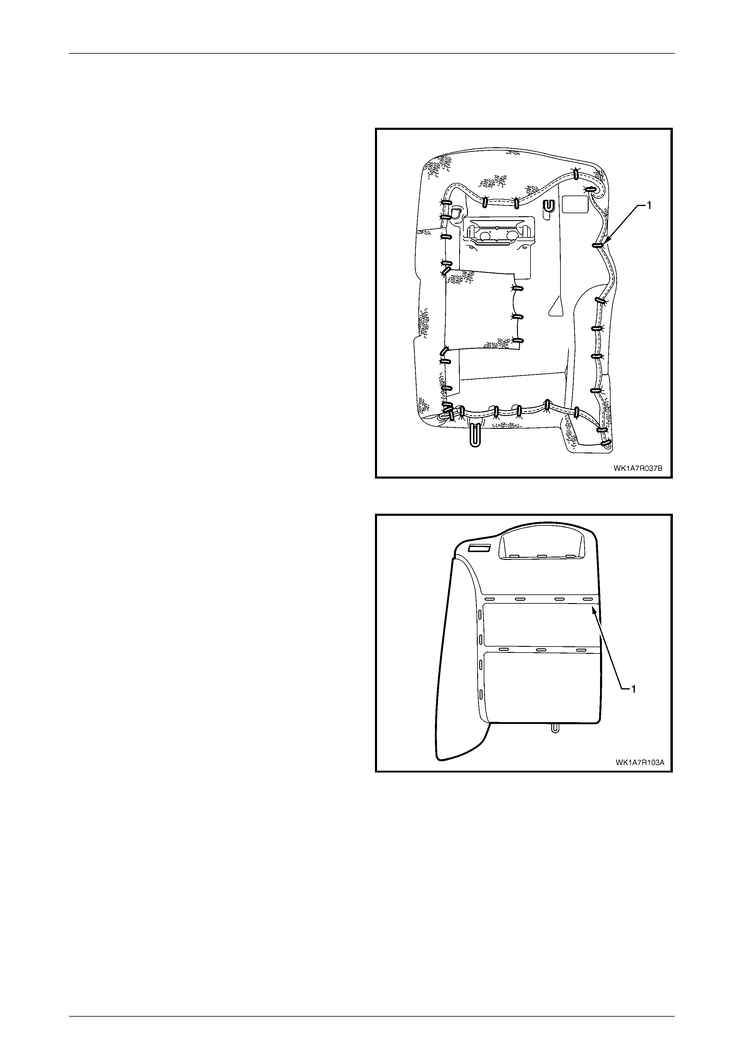
Seat Assemblies Page 1A7A–307
Page 1A7A–307
Rear Seat Type 3 and 4
Remove
1 Place the seat-back assembly face down on a clean
surface.
2 Using the following sequence of operations, use bolt
cutters or side cutters to remove approximatel y 31 hog
rings (1) attaching the outer sections of the cover to
the rear seat-back pad and frame assembly in the
positions shown.
NOTE
Care must be taken when removing the hog
rings, not to damage the rear seat-back cover.
All hog rings will be damaged in this operation
and will require replacement.
Figure 1A7A – 242
3 Continue to remove the rear seat-back cove r from the
front of the pad assembly (1) by cutting the 11 hog
rings as they are revealed using bolt cutters or side
cutters.
Figure 1A7A – 243
4 Remove the head restraint sleeves, refer to Head Restraint Sleeve.
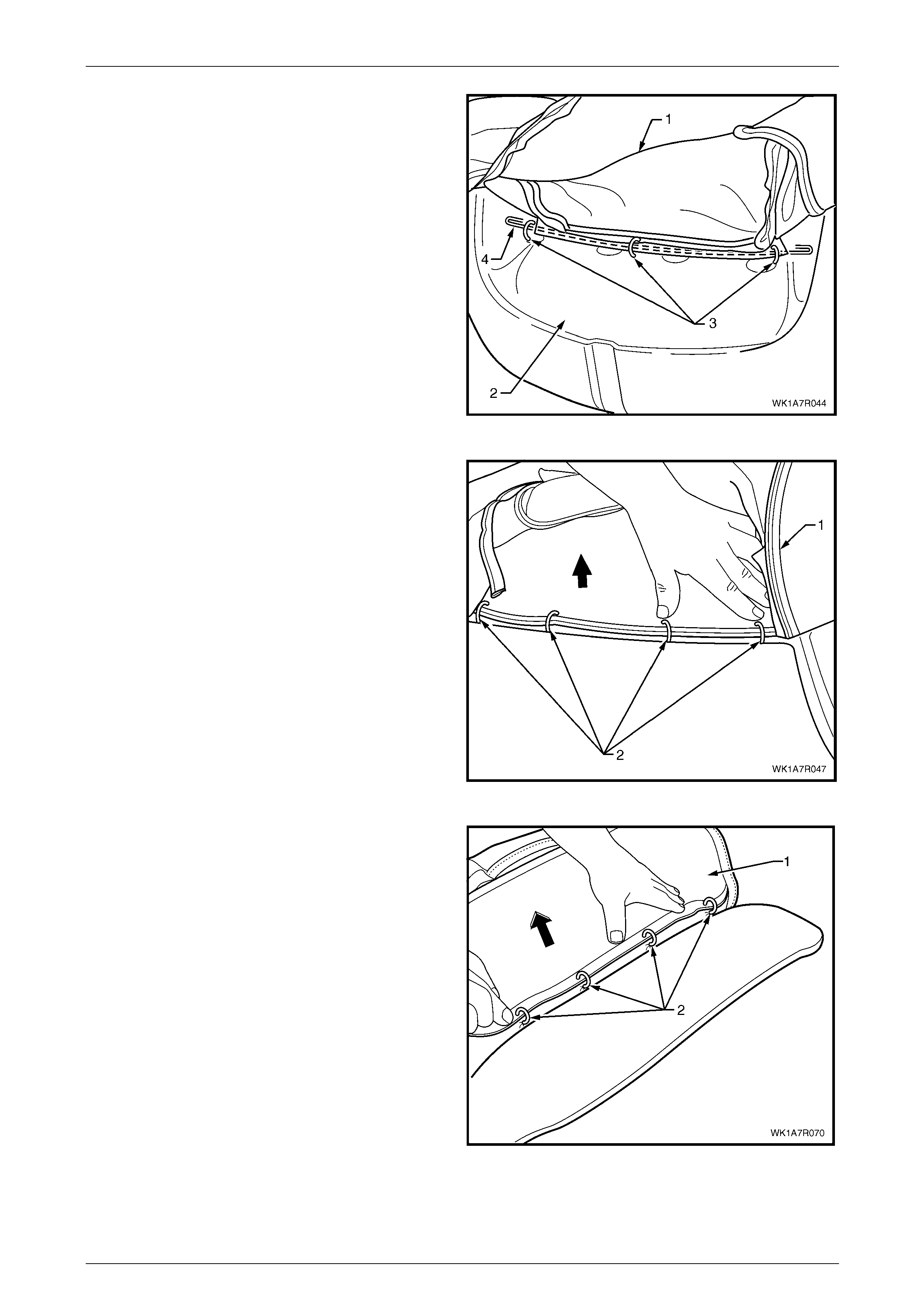
Seat Assemblies Page 1A7A–308
Page 1A7A–308
5 Fold the upper portion of the rear seat-back cover (1)
over the rear seat-back pad assembly (2).
6 Cut the three hog rings (3) attaching the retaining wire
(4) to the frame assembly.
Figure 1A7A – 244
7 Fold the cover (1) over the top to reveal the four hog
rings (2) in the continuation of the outer groove
running across the top of the pad and cut the hog rings
to remove.
Figure 1A7A – 245
8 While holding the rear seat-back pad assembly (1),
pull the outboard edge of the cover away from the rear
seat-back pad and cut the four hog rings (2) along the
outer groove.
Figure 1A7A – 246
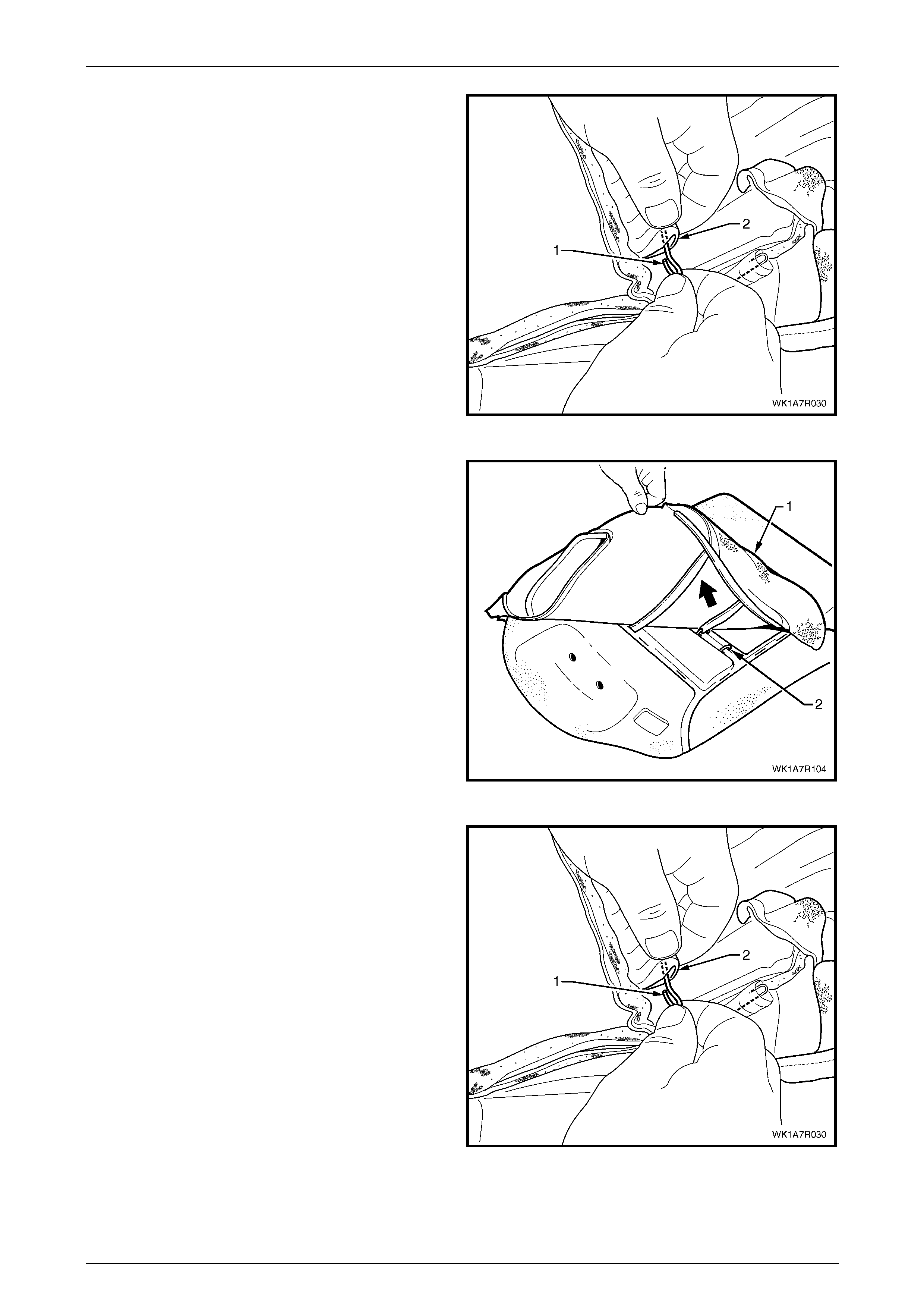
Seat Assemblies Page 1A7A–309
Page 1A7A–309
9 If required, remove the retaining wire (1) from the
casing (2) attached to the cover.
Figure 1A7A – 247
10 Continue to fold the rear seat-back cover (1) to wards
the centre revealing the outer hog ri ng (2) in the lower
horizontal groove.
11 Cut the outer hog ring and continu e until all three hog
rings have been removed.
Figure 1A7A – 248
12 If required, remove the retaining wire (1) from the
casing (2) attached to the cover.
13 Remove the rear seat-back cover.
Figure 1A7A – 249
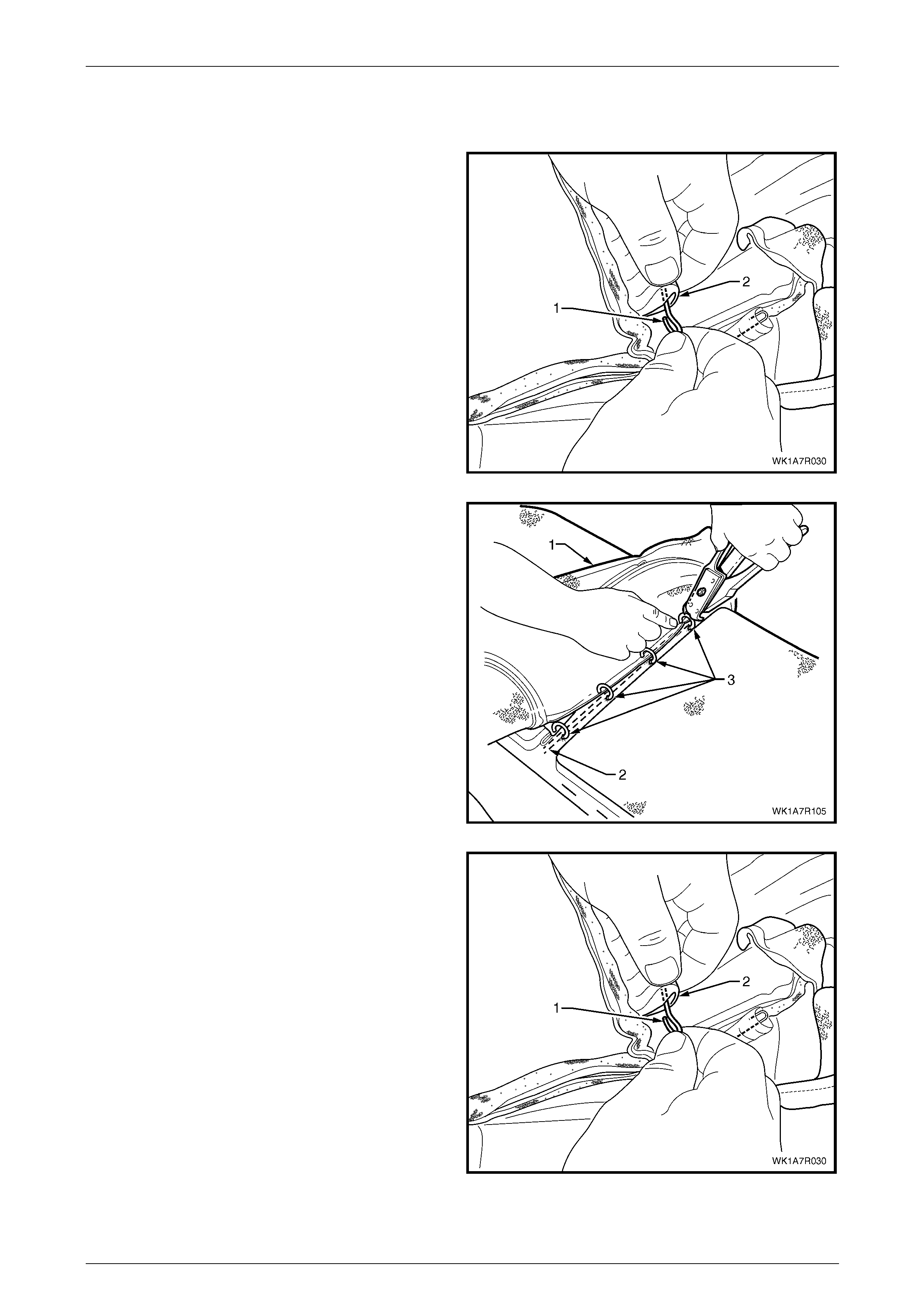
Seat Assemblies Page 1A7A–310
Page 1A7A–310
Reinstall
1 Using the following sequence of operations, align the rear seat-back cover to the pad assembly (1) and attach with
11 hog rings in the locations shown, refer Figure 1A7A – 243
2 Reinstall the retaining wire (1) into the lower horizontal
groove casing (2) attached to the cover.
Figure 1A7A – 250
3 Align the cover (1) to the lower horizontal groove in the
pad (2) and attach with four hog rings (3), using hog
ring pliers.
Figure 1A7A – 251
4 Reinstall the retaining wire (1) into the outer groove
casing (2) attached to the cover.
Figure 1A7A – 252
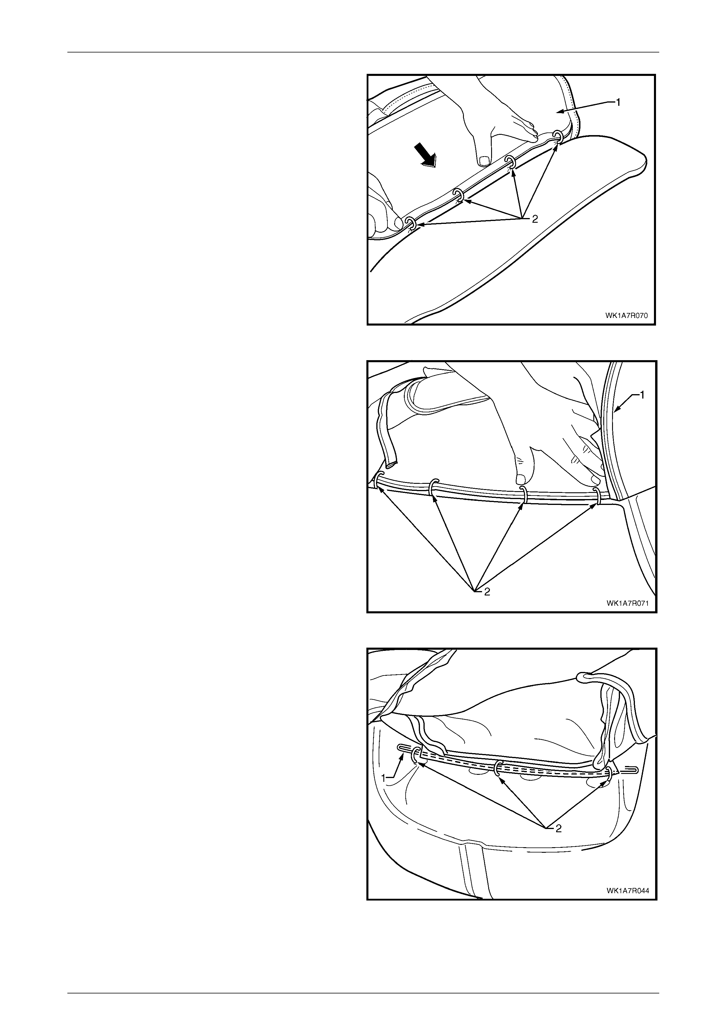
Seat Assemblies Page 1A7A–311
Page 1A7A–311
5 Align the cover (1) to the outer the groove along the
outboard edge of the pad and attach with four hog
rings (2).
Figure 1A7A – 253
6 Continue to fit the cover (1) to the upper horizontal
groove and attach with four hog rings (2).
Figure 1A7A – 254
7 Fold the cover into the head restraint area a nd
attached the retaining wire (1) for the head re straint
with three hog rings (2) to the frame.
Figure 1A7A – 255
8 Place the seat-back assembly face down on a clean surface and using the following sequence of operati ons,
continue attaching the rear seat-back cover (1) to the pad assembly (2) with hog rings (3), approximately 31 places
in the positions shown, refer Figure 1A7A – 242.

Seat Assemblies Page 1A7A–312
Page 1A7A–312
9 Starting at the upper inboard corner of the rear
seat-back, pull the cover (1) over the corner and
attach to the wire frame (2) with three hog rings (3).
Figure 1A7A – 256
10 While pulling the outboard side corner of the cover (1)
over the top and towards the centre, fix with four hog
rings (2) to the wire frame (3).
Figure 1A7A – 257
11 Continue at the outboard lower corner and attach the
cover (1) to the frame (2), by pulling the cover tight
and fixing with seven hog ri ngs (3).
Figure 1A7A – 258

Seat Assemblies Page 1A7A–313
Page 1A7A–313
12 Continue at the inboard lower corner and attach the
cover (1) to the frame (2), by pulling the cover tight
and fixing with four hog rings (3).
13 Attach the seat-back cover lower pi ping overhang (4)
with one hog ring (5) back on to the lower piping.
Figure 1A7A – 259
14 Attach the first aid kit pouch (1) to the frame (2) with
five hog rings (3).
NOTE
Make sure the rear seat-back cover is fitted
neatly by hand into all corners and contours of
the seat pad and is free from any creases.
15 Continue along the inboard edge and attach the cover
to the frame, by pulling the cover tight and fixing with a
further three hog rings.
Figure 1A7A – 260
Rear Seat Type 5
Surebond rear seat-back cover and pad are glued together as an assembly and are not serviced. If either the pad or the
cover requires replacement both will have to be replaced as a combined unit.
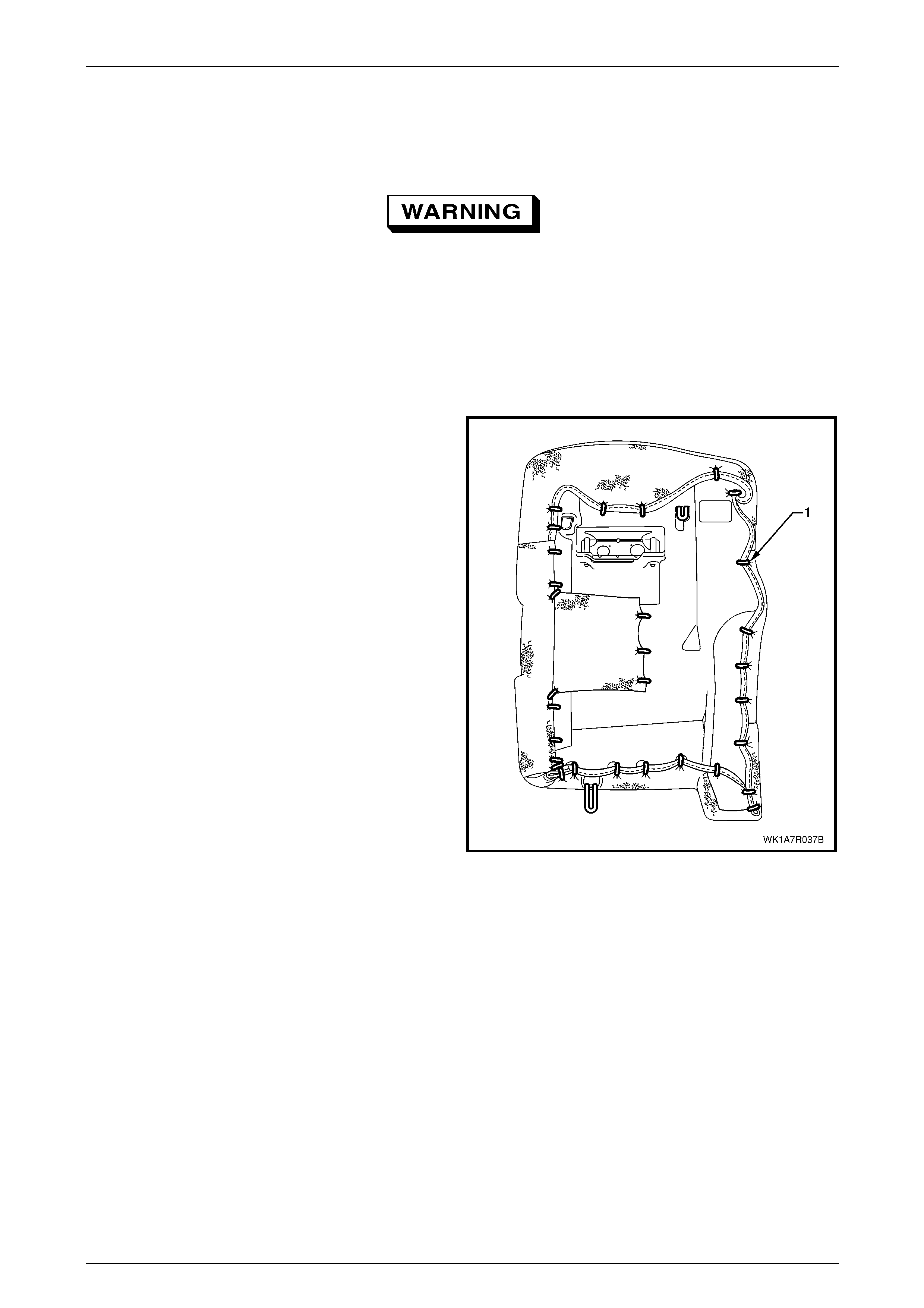
Seat Assemblies Page 1A7A–314
Page 1A7A–314
Rear Seat Type 8
Remove
Safety glasses an d work glo ves must be w orn
at all times when removing the hog rings.
NOTE
The following procedures are applicable to both
left and right-hand rear seat-back assemblies.
1 Place the rear seat-back assembly face down.
2 Using bolt cutters or side cutters, remove
approximately 31 hog rings (1) attaching the outer
sections of the cover to the rear seat-back pad and
frame assembly.
NOTE
Care must be taken when removing the hog
rings, not to damage the rear seat-back cover.
All hog rings will be damaged in this operation
and will require replacement.
3 Remove the rear head restraint sleeve, refer to
Head Restraint Sleeve.
Figure 1A7A – 261
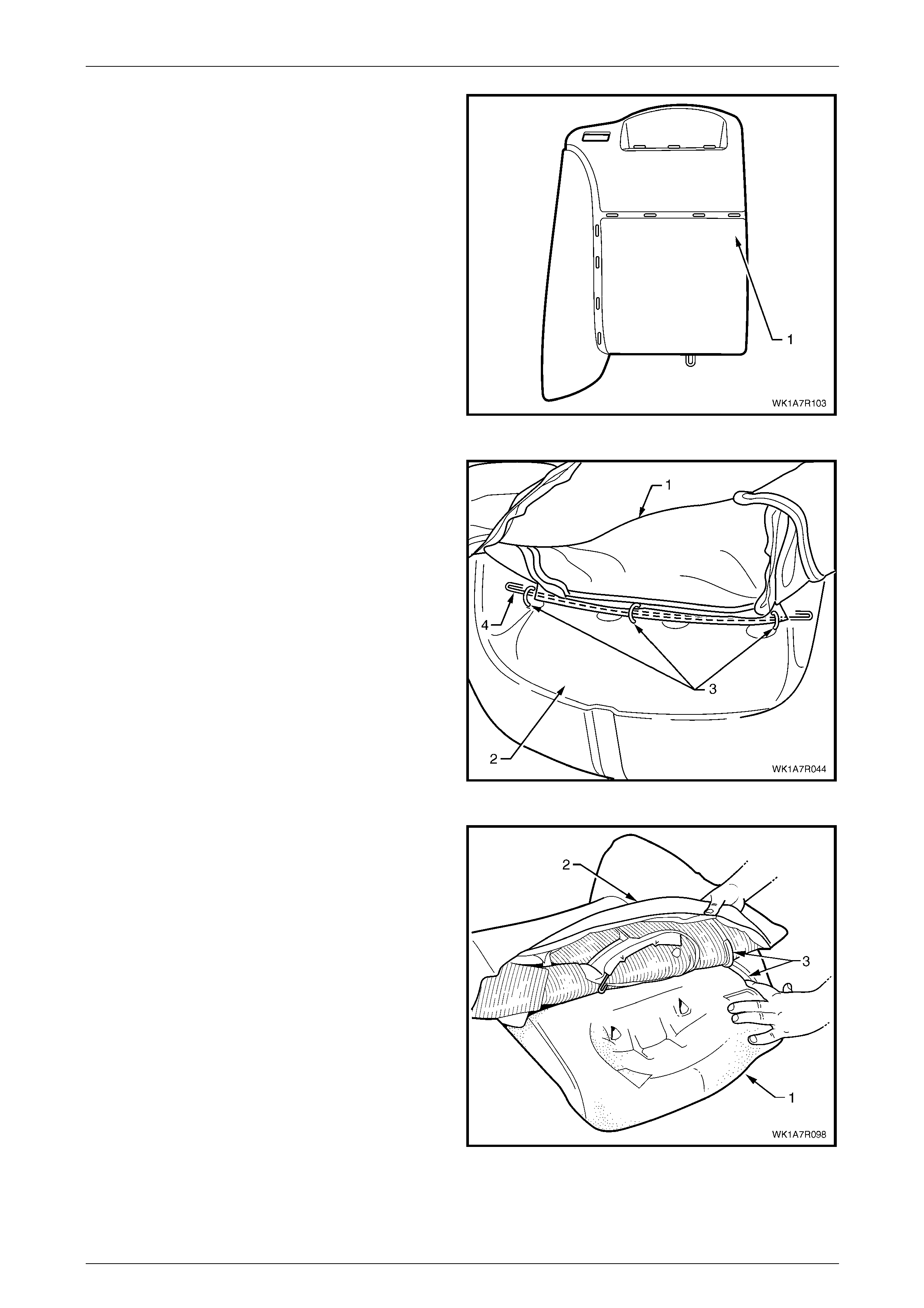
Seat Assemblies Page 1A7A–315
Page 1A7A–315
4 After removing the rear hog rings, continue with the
following sequence of operati ons and cut the hog rings
attaching the cover to the front side of the pad (1), as
they are revealed using bolt cutters or side cutters at
the locations shown.
Figure 1A7A – 262
5 Fold the upper portion of the rear seat-back cover (1)
over the rear seat-back pad assembly (2).
6 Cut the three hog rings (3) attaching the retaining wire
(4) to the frame assembly.
Figure 1A7A – 263
7 While holding the rear seat-back pad assembly (1),
pull the upper corner of the cover (2) away from the
rear seat-back pad to disengage the hook and loop
strip (3).
Figure 1A7A – 264
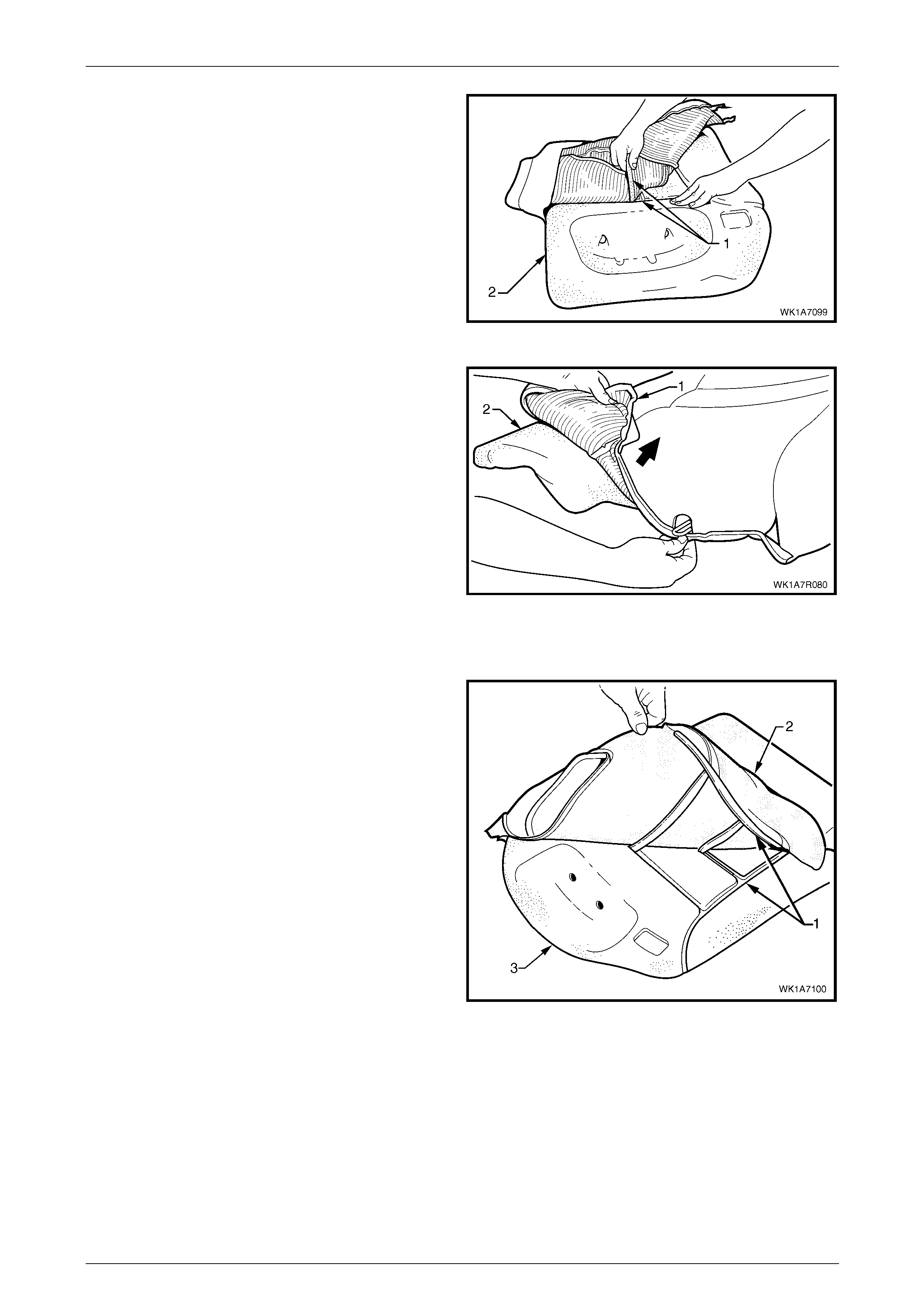
Seat Assemblies Page 1A7A–316
Page 1A7A–316
8 Remove the one or two cross hook and loop strips (1)
while holding the rear seat-back pad (2).
Figure 1A7A – 265
9 Fold the lower corner of the cover (1) over the
seat-back pad (2).
10 Remove the rear seat-back cover.
Figure 1A7A – 266
Reinstall
1 Align the outer hook and loop strip (1) on the
seat-back cover (2), with the rear seat-back pad (3).
Figure 1A7A – 267
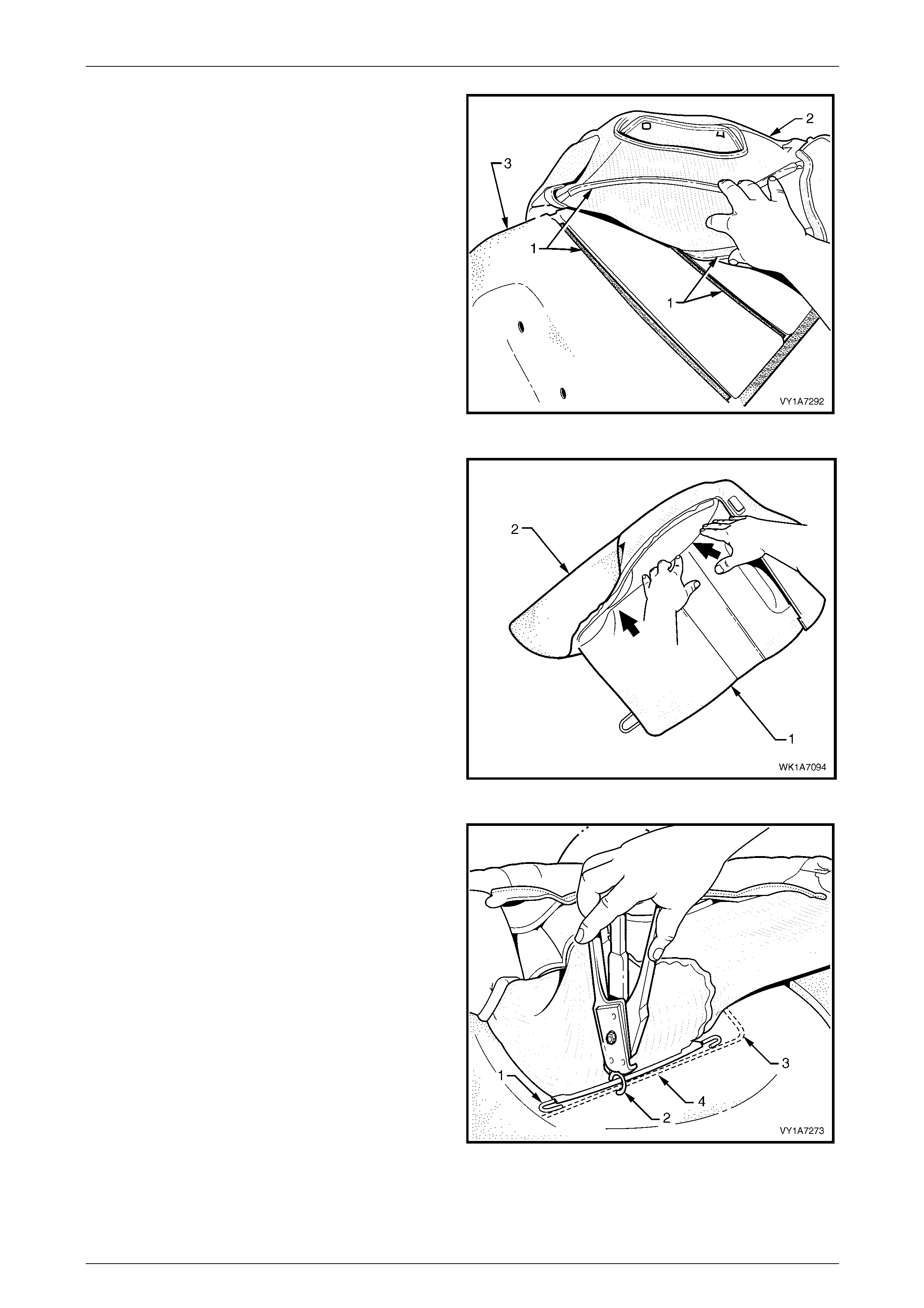
Seat Assemblies Page 1A7A–317
Page 1A7A–317
2 Align the two cross hook and loop strips (1), on the
rear seat-back cover (2), with the rear seat -back pad
(3).
Figure 1A7A – 268
3 Press the folded edge of the rear seat-back cover (1)
firmly into the corresponding groove i n the se at-back
pad (2) to engage the hook and loop strip.
Figure 1A7A – 269
4 Attach the head restraint retaining wire (1) with hog
ring (2), three places to the frame (3) using hog ring
pliers.
Figure 1A7A – 270
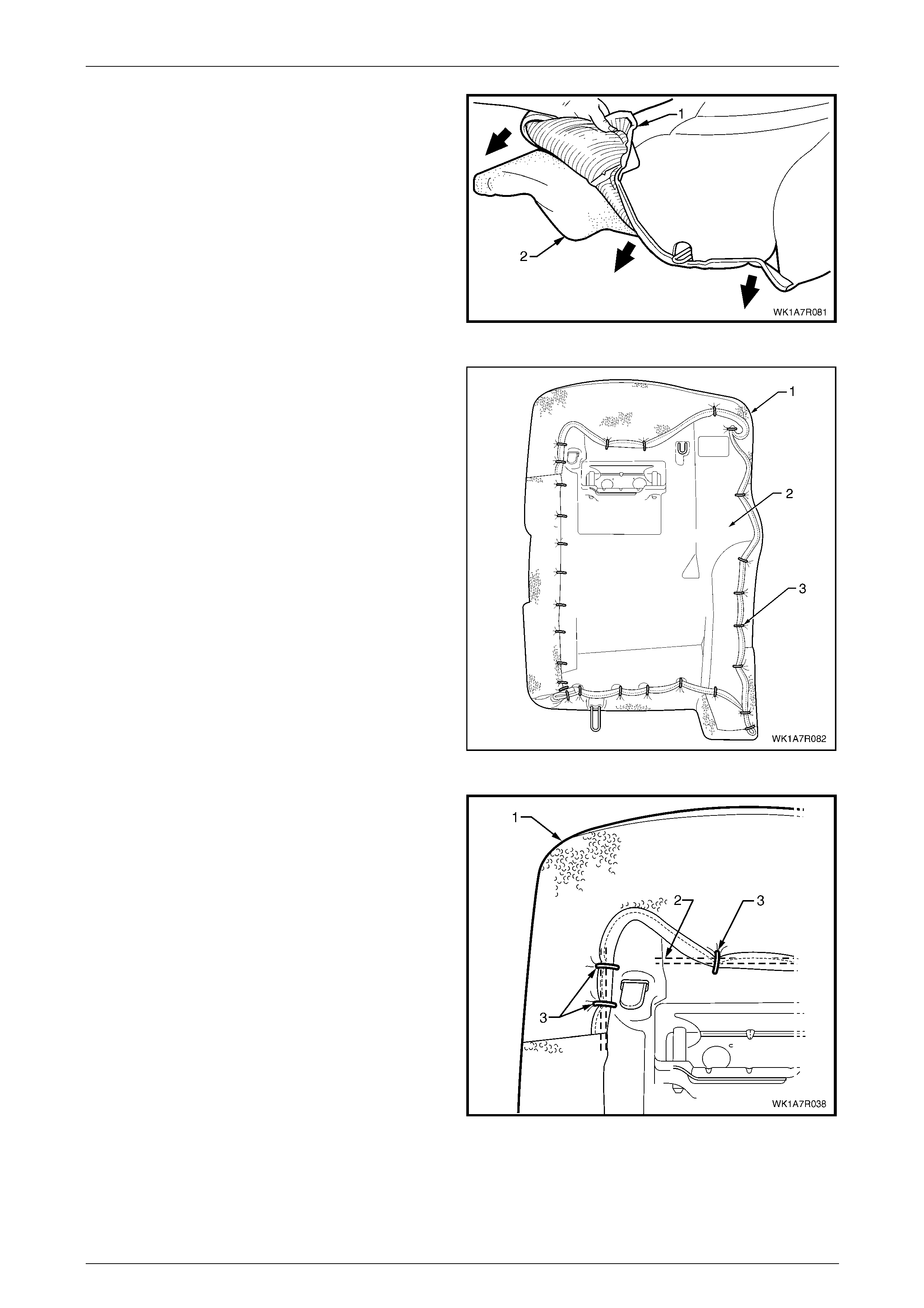
Seat Assemblies Page 1A7A–318
Page 1A7A–318
5 Roll the lower corner of the cover (1) over the rear
seat-back pad (2).
6 Roll the sides of the cover over the seat-back pad.
7 Roll the upper corners of the cover over the seat-back
pad.
NOTE
Make sure the cover is fitted neatly by hand into
all corners and contours of the seat back-pad.
Figure 1A7A – 271
8 Using the following sequenc e of operations, attach the
rear seat-back cover (1) to the rear seat-back pad and
frame assembly (2), with approximately 31 hog rin gs
(3), in the positions shown.
Figure 1A7A – 272
9 Starting at the upper outboard corner of the rear
seat-back, pull the cover (1) over the corner and
attach to the wire frame (2) with three hog rings (3).
Figure 1A7A – 273
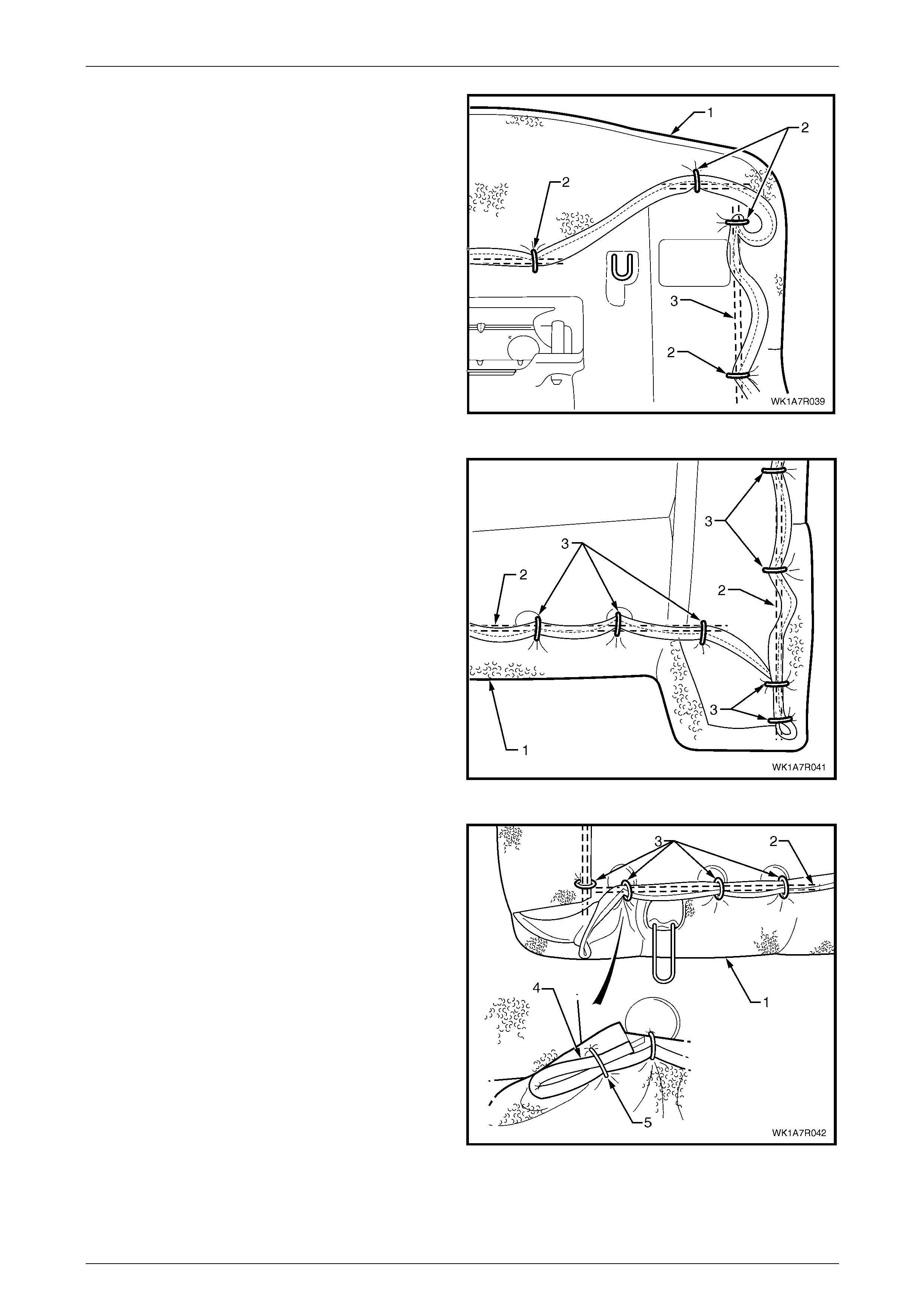
Seat Assemblies Page 1A7A–319
Page 1A7A–319
10 While pulling the outboard side corner of the cover (1)
over the top and towards the centre, fix with four hog
rings (2) to the wire frame (3).
Figure 1A7A – 274
11 Continue at the outboard lower corner and attach the
cover (1) to the frame (2), by pulling the cover tight
and fixing with seven hog ri ngs (3).
Figure 1A7A – 275
12 Continue at the inboard lower corner and attach the
cover (1) to the frame (2), by pulling the cover tight
and fixing with four hog rings (3).
13 Attach the seat-back cover lower pi ping overhang (4)
with one hog ring (5) back on to the lower piping.
Figure 1A7A – 276
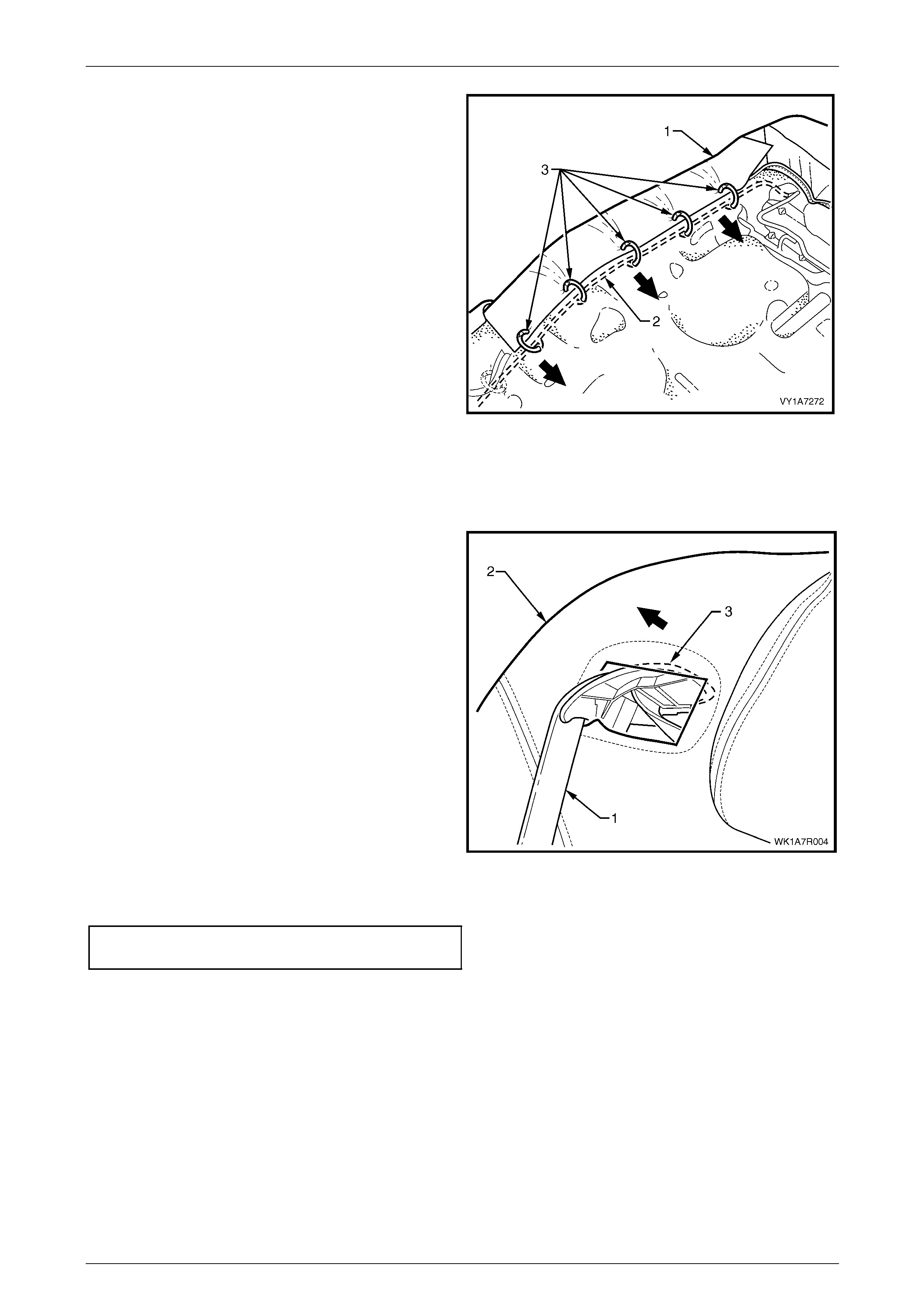
Seat Assemblies Page 1A7A–320
Page 1A7A–320
14 Continue attaching the cover (1) to the frame (2), by
pulling the cover tight and fixing with five hog rings (3).
Figure 1A7A – 277
Reinstall
Reinstallation of the rear seat-back assembly is the reverse of the removal procedure, noting the following:
1 Feed the seatbelt (1) in through rear seat-back
assembly (2).
2 Position the seatbelt escutcheon (3) at an angle and
feed it through the rear seat-back assembly.
NOTE
Ensure the seatbelt is not twisted and its
operation is free from any interference
Figure 1A7A – 278
3 Tighten all attaching bolts to the spec ified torque.
Rear seat-back assembly attaching
bolt torque specification..........................25.0 – 35.0 Nm
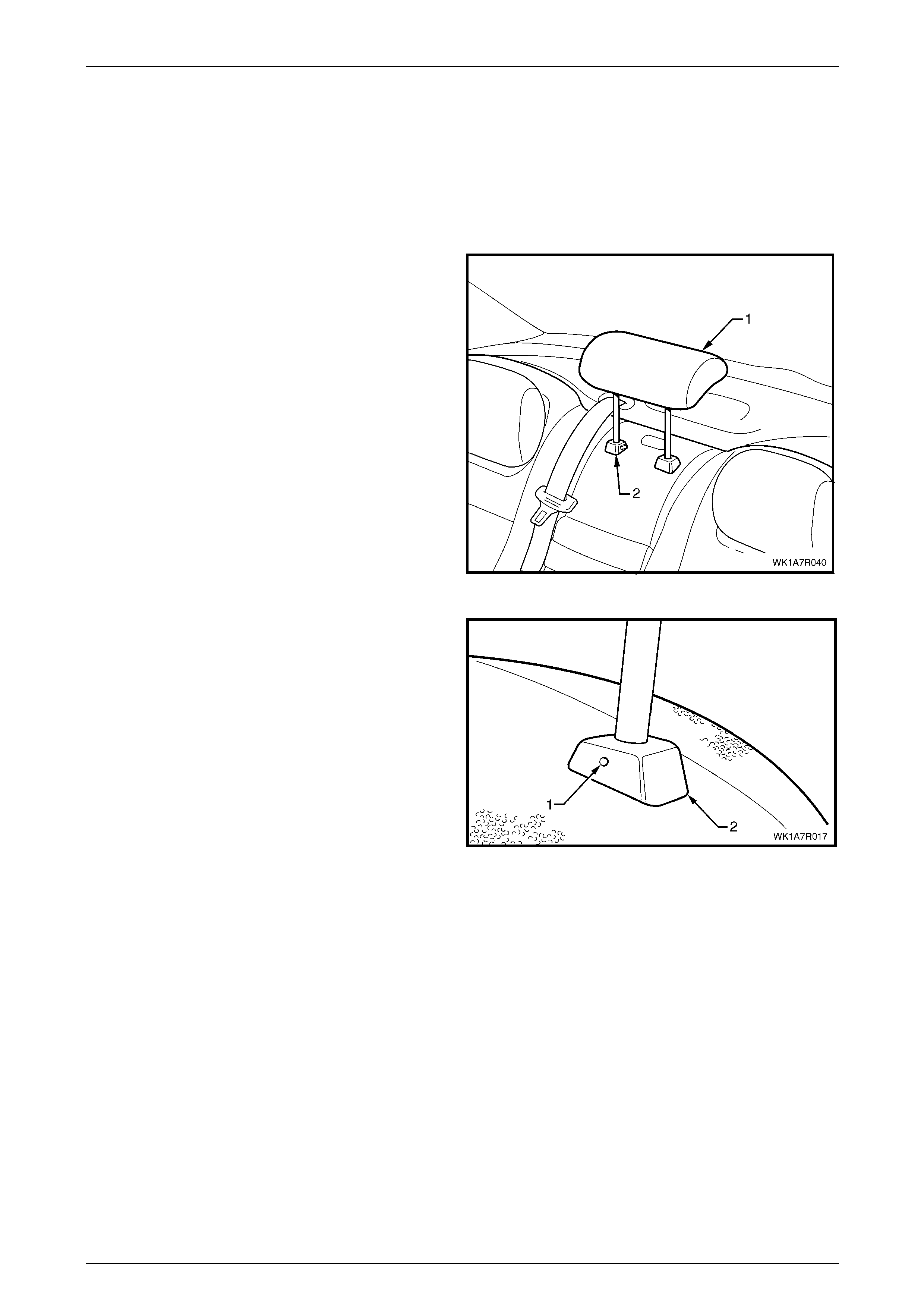
Seat Assemblies Page 1A7A–321
Page 1A7A–321
6.5 Rear Seat-back Centre Head Restraint
Assembly
LT Section No. – 14-350
Remove
1 Raise the rear seat-back centre head restraint (1) to
the first stop position.
2 Depress the head restraint sleeve height adjuster
lock (2) and raise the head restraint to the upper stop
position.
Figure 1A7A – 279
3 Manufacture a suitable size probe and insert into the
hole (1) in the left-hand head restraint sleeve (2).
4 Push the probe in slightly whil e applying slight upward
pressure on the head restrain t and remove the head
restraint completely out of the sleeve.
Figure 1A7A – 280
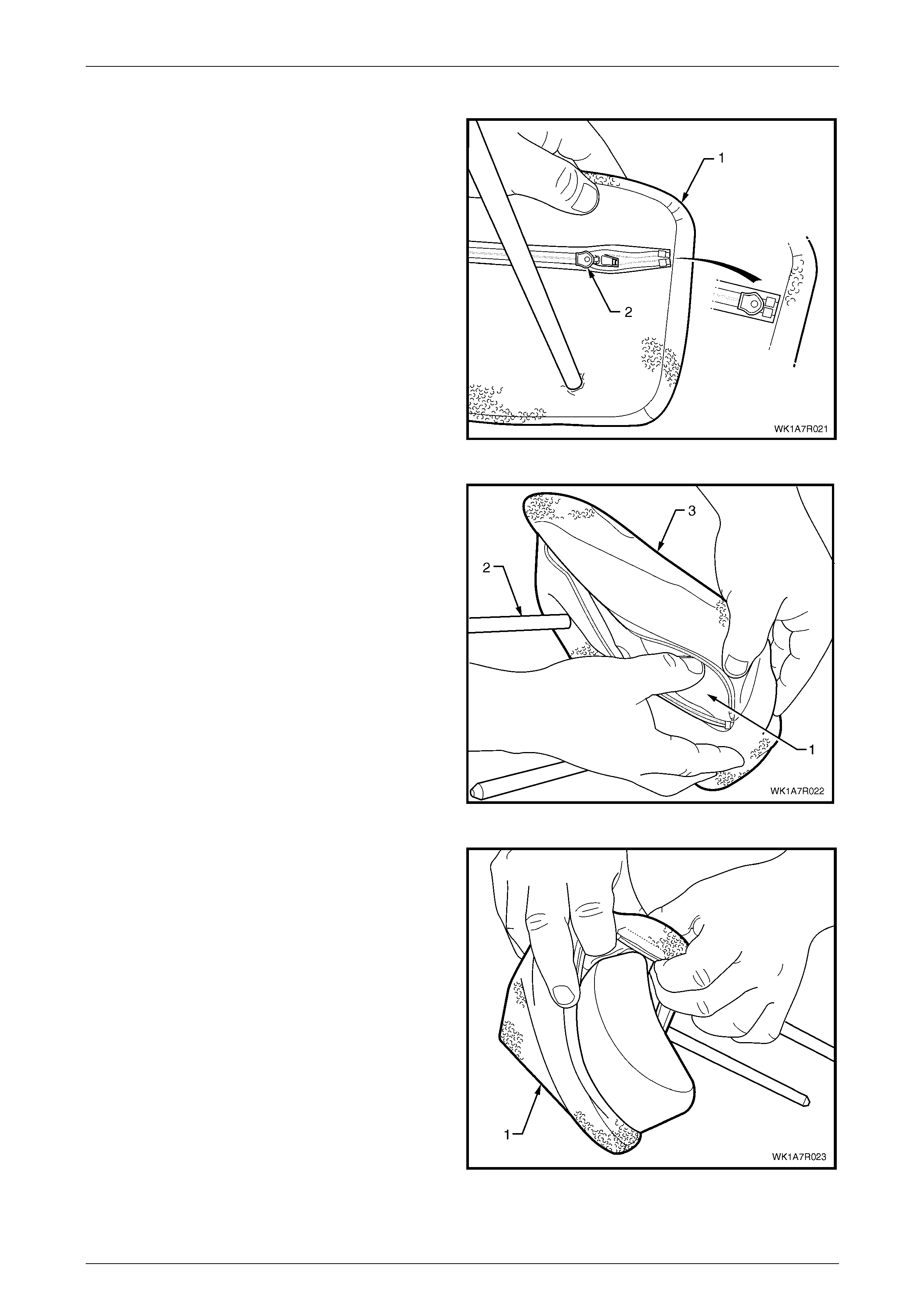
Seat Assemblies Page 1A7A–322
Page 1A7A–322
Disassemble
1 While holding the rear seat-back centre head restraint
(1) upside down, un-zip the cover taking note that the
tag for the zip (2) is located on the inside of the cover.
Figure 1A7A – 281
2 Beginning at one end, compr ess the foam (1) towards
the head restraint post (2) and begin to pull the cover
(3) over the pad.
3 Repeat this process for the other side.
Figure 1A7A – 282
4 Remove the cover (1) from the pad and slide off the
post.
Figure 1A7A – 283

Seat Assemblies Page 1A7A–323
Page 1A7A–323
Reassemble
Reassembly of the rear seat-back centre head restraint cover is the reverse of the removal process noting the follo wing:
1 Position the head restraint cover over the post.
2 Starting at one end of the head restraint, insert the pad into the cover and working from one end to another, push
the pad into the cover until it is completely inserted.
3 Work the cover over the head restraint so that the cover is smooth and free from creases.
4 Close the zip ensuring the tag is located on the inside of the cover.
Reinstall
Position the head restraint in the head restraint sleeves a nd push the rear seat-back centre head restrain t down firmly.

Seat Assemblies Page 1A7A–324
Page 1A7A–324
6.6 Rear Seat-back Centre Armrest
Assembly
LT Section No. – 14-325
Remove
1 Lower the armrest assembly (1) and disengage the trim flap J-strips (2) from the armrest hinge to gain access to
the retaining screws, refer to Figure 1A7A – 284.
2 Remove the retaining screw (3), four places, from the rear seat-back centre tra y (4), two from above the armrest
and two from below.
3 Remove the armrest assembly.
Figure 1A7A – 284
Disassemble Rear Seat Type 1 – 4
Rear Seat-back Centre Armrest Hinge
Remove
Remove the three screws (1) attaching the hinge (2) to the
rear seat-back centre armrest assembly (3).
Figure 1A7A – 285
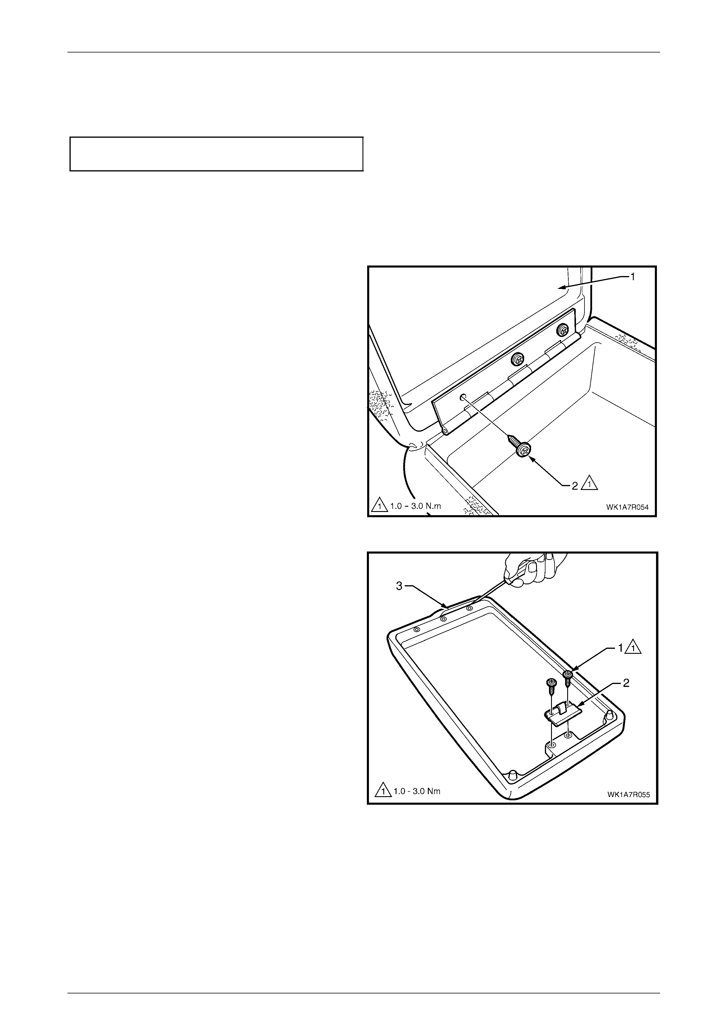
Seat Assemblies Page 1A7A–325
Page 1A7A–325
Reinstall
Reinstallation of the rear seat-back centre armrest hinge is reverse of the removal procedure, notin g the following:
Ensure all attaching screws are tightened to the specified torque.
Rear seat-back centre armrest hinge
attaching screw torque specification...........1.0 – 3.0 Nm
Rear Seat-back Centre Armrest Lid and Cover
If required, remove the armrest assembly, refer to 6.6 Rear Seat-back Centre Armrest Assembly.
Remove
1 Open the rear seat-back centre armrest lid (1), remove
the three screws (2) and remove the lid.
Figure 1A7A – 286
2 Remove the two screws (1), attaching the armrest lid
latch (2).
3 Using a suitable size scre wdriver, gently prise up the
retaining strip (3), three places.
4 Remove the cover from the rear seat-back centre
armrest lid.
Figure 1A7A – 287
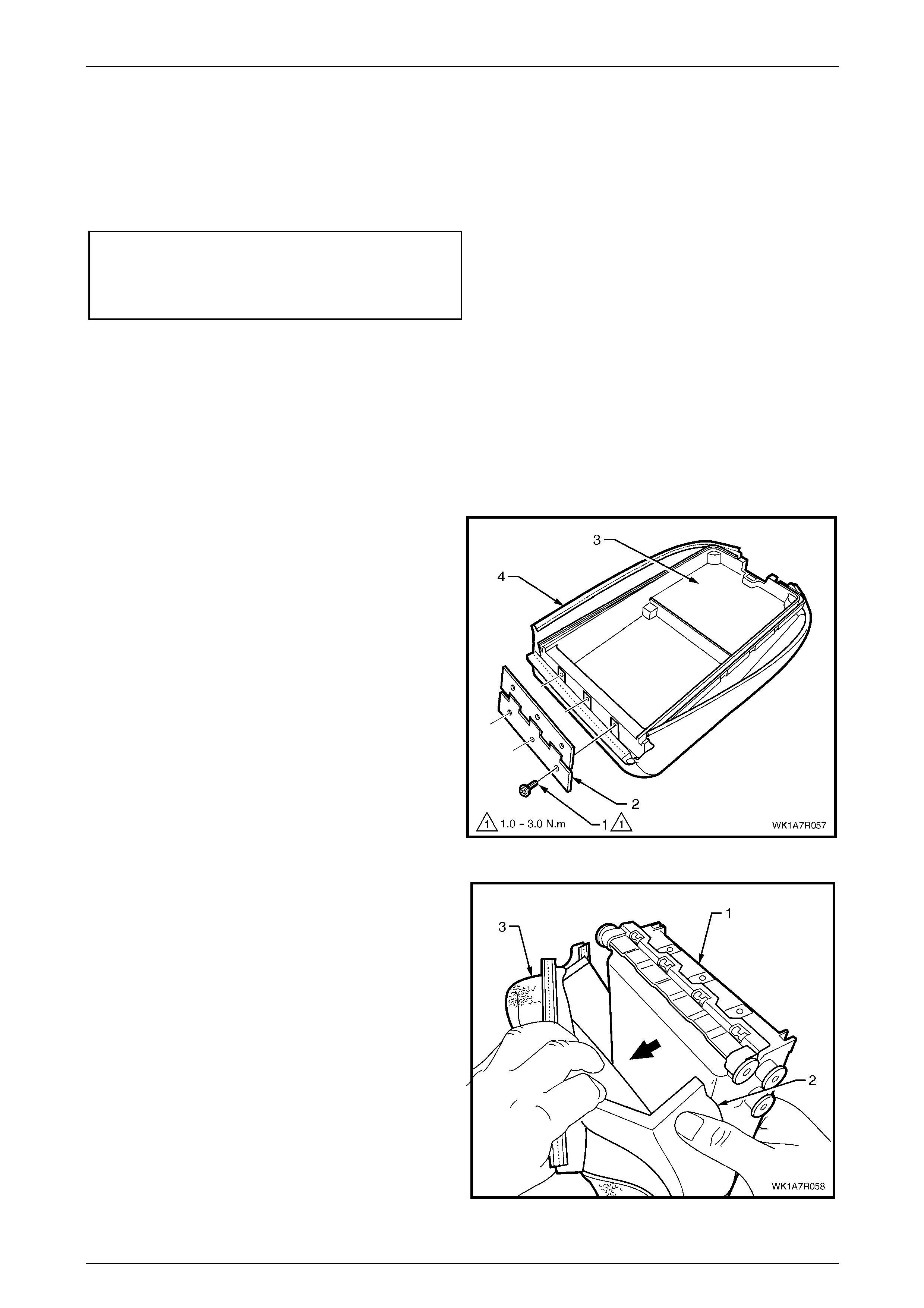
Seat Assemblies Page 1A7A–326
Page 1A7A–326
Reinstall
Reinstallation of the rear seat-back centre armrest lid cover is the reverse of the removal proce dure, noting the following:
1 Fit the cover by hand ensuring the cover is free from creases.
2 Ensure the retainer strips are located full y into the grooves.
3 Tighten all attaching screws to the specified torque.
Rear seat-back centre armrest lid
attaching screw torque specification...........1.0 – 3.0 Nm
Rear seat-back centre armrest lid latch
attaching screw torque specification...........1.0 – 3.0 Nm
Rear Seat-back Centre Armrest Deposit Box, Cover and Cup Holder
To remove the rear seat-back centre armrest deposit box, cup holder or cover, the cover and cup holder need to be
removed from the rear seat-back centre armrest assembly as a combined unit. To assist the technician to disassemble
the seat-back centre armrest assembly without cross referencing to different sections, the deposit box, cover and cup
holder remove and reinstall procedures are all covered in the same procedure.
Remove
1 If required, remove the rear seat-back centre armrest lid, refer to Rear Seat-back Centre Armrest Lid and Cover.
2 Remove the screw (1), three places, attaching the rear
seat-back centre armrest lid hinge (2) to the deposit
box assembly (3).
3 Gently prise up the retaining s trip (4), three places.
Figure 1A7A – 288
4 While holding the deposit box assembly (1) g ently pull
the foam pad (2) and cover (3) away from the deposit
box.
Figure 1A7A – 289
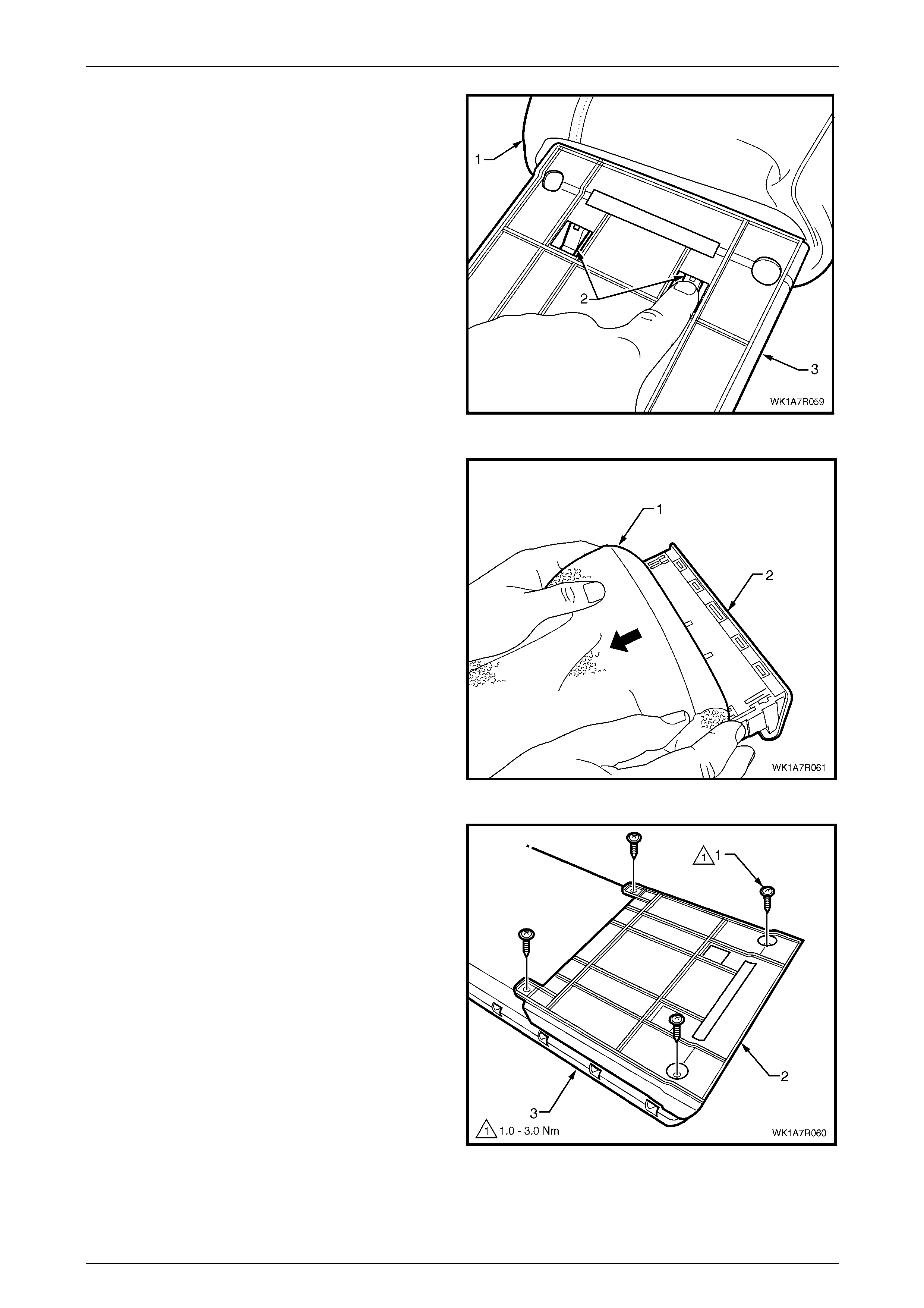
Seat Assemblies Page 1A7A–327
Page 1A7A–327
5 With the cover (1) folded back from the deposit box
assembly, depress the cup holder retaining tabs (2)
and remove the cup holder with the cover out of the
cup holder housing (3).
Figure 1A7A – 290
6 Remove the cover (1) from the cup holder (2) b y
gently pulling the cover back over the cup h older.
Figure 1A7A – 291
7 Remove the four screws (1) attaching the cup holder
housing (2) to the deposit box (3).
Figure 1A7A – 292
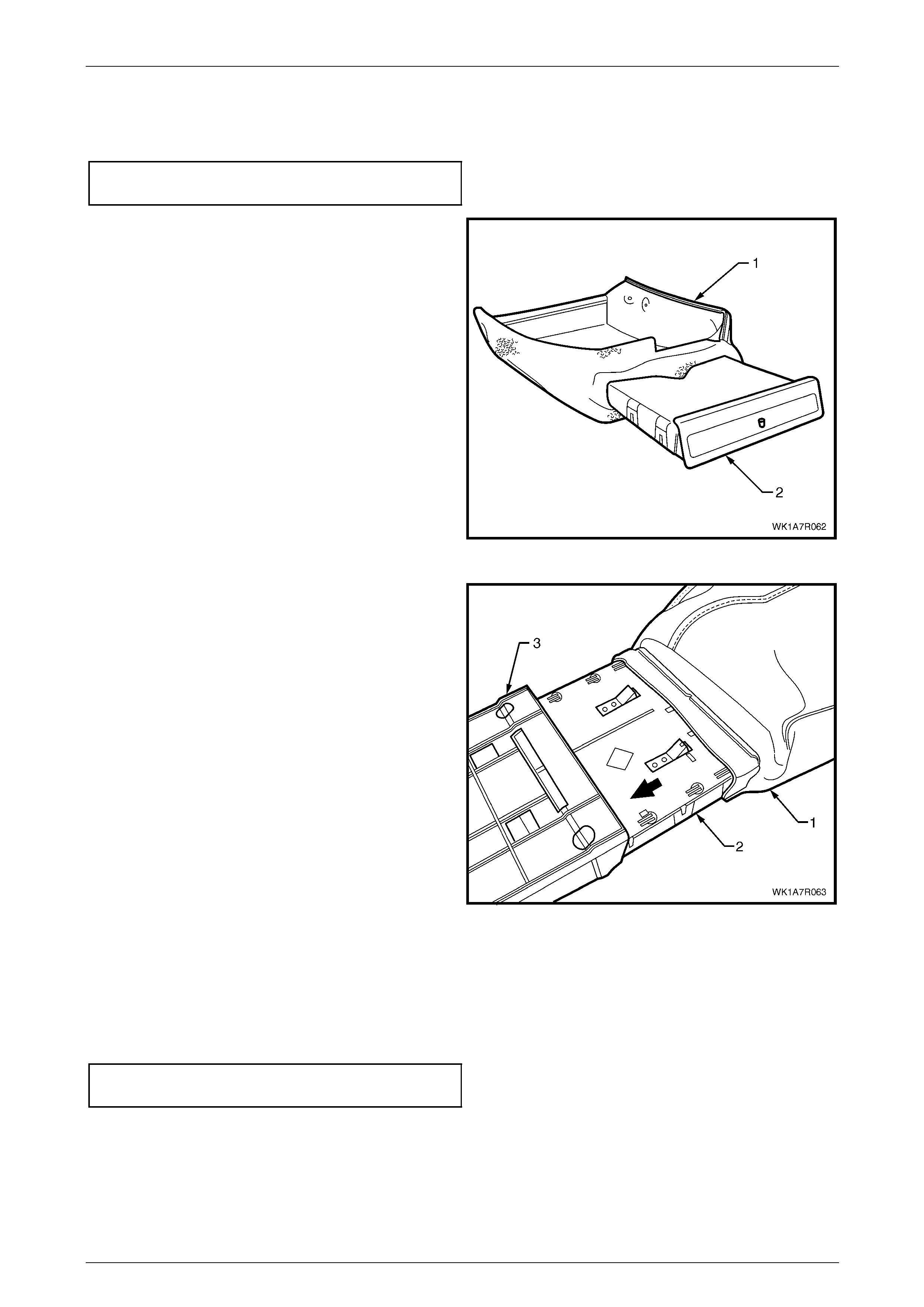
Seat Assemblies Page 1A7A–328
Page 1A7A–328
Reinstall
1 Reinstall the cup holder housing to the deposit box and tighten all attaching screws to the specified torque, refer to
Figure 1A7A – 292.
Cup holder housing attaching
screw torque specification...........................1.0 – 3.0 Nm
2 Slide the cover (1) over the cup holder (2) ensuring the
cover fits neatly to the edge of the cup holder.
Figure 1A7A – 293
3 With the cover (1) folded back, slide the cup hol der (2)
into the cup holder housing (3) attached to the deposit
box, ensuring the cover fits neatl y into the cup holder
housing and the retaining clips lock in the cup holder
housing.
Figure 1A7A – 294
4 Reinstallation of the cover, pad and hinge is the reverse of the removal procedure noting the following:
a Ensure the cover is fitted neatly by hand and free from creases.
b All retainer strips are secured correctly.
c Tighten the rear seat-back centre armrest lid hinge attaching screws to the specified torque.
Rear seat-back centre armrest lid hi nge
attaching screw torque specification...........1.0 – 3.0 Nm
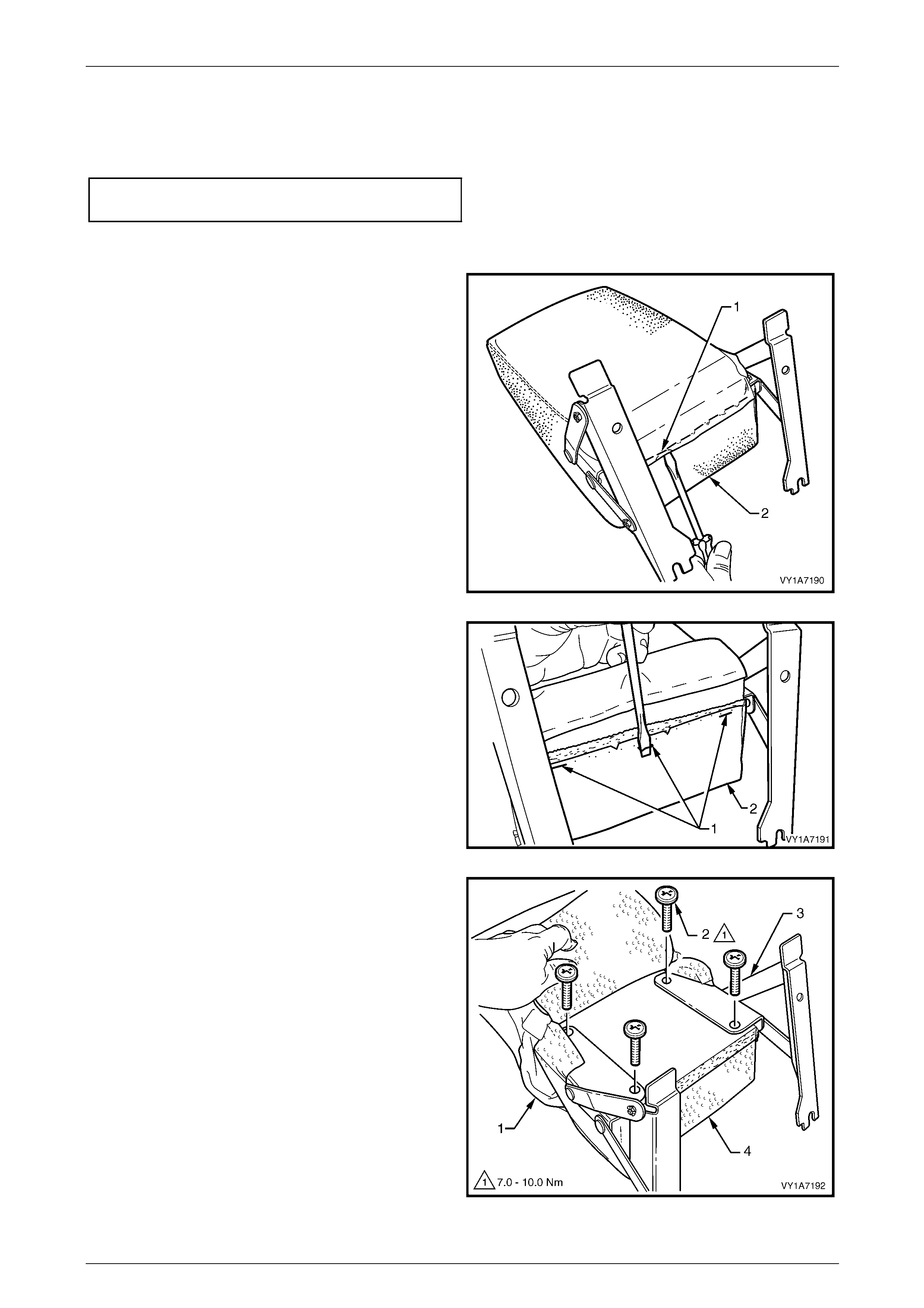
Seat Assemblies Page 1A7A–329
Page 1A7A–329
Reassemble
Reassembly of the rear seat-back centre armrest assembly is the reverse of the removal procedure, noting the following:
Ensure the armrest assembly hinge is installed before the cover is fitted and the attaching screws are tightened to the
specified torque.
Armrest hinge attaching screw
torque specification...................................7.0 – 10.0 Nm
Disassemble Rear Seat Type 5 – 8
1 Remove the nine staples (1) securing the u pper flap
armrest cover (2) to the armrest pad assembly.
Figure 1A7A – 295
2 Remove the three staples (1) securing the lo wer flap
of the armrest cover (2) to the armrest pad assembly.
Figure 1A7A – 296
3 Pull the cover (1) along the armrest to allow access to
the hinge retaining screws.
4 Remove the four screws (2) securing the armrest
hinge (3) to the armrest assembly (4) and remove the
hinges.
5 Remove the armrest cover from the armrest pad
assembly.
Figure 1A7A – 297
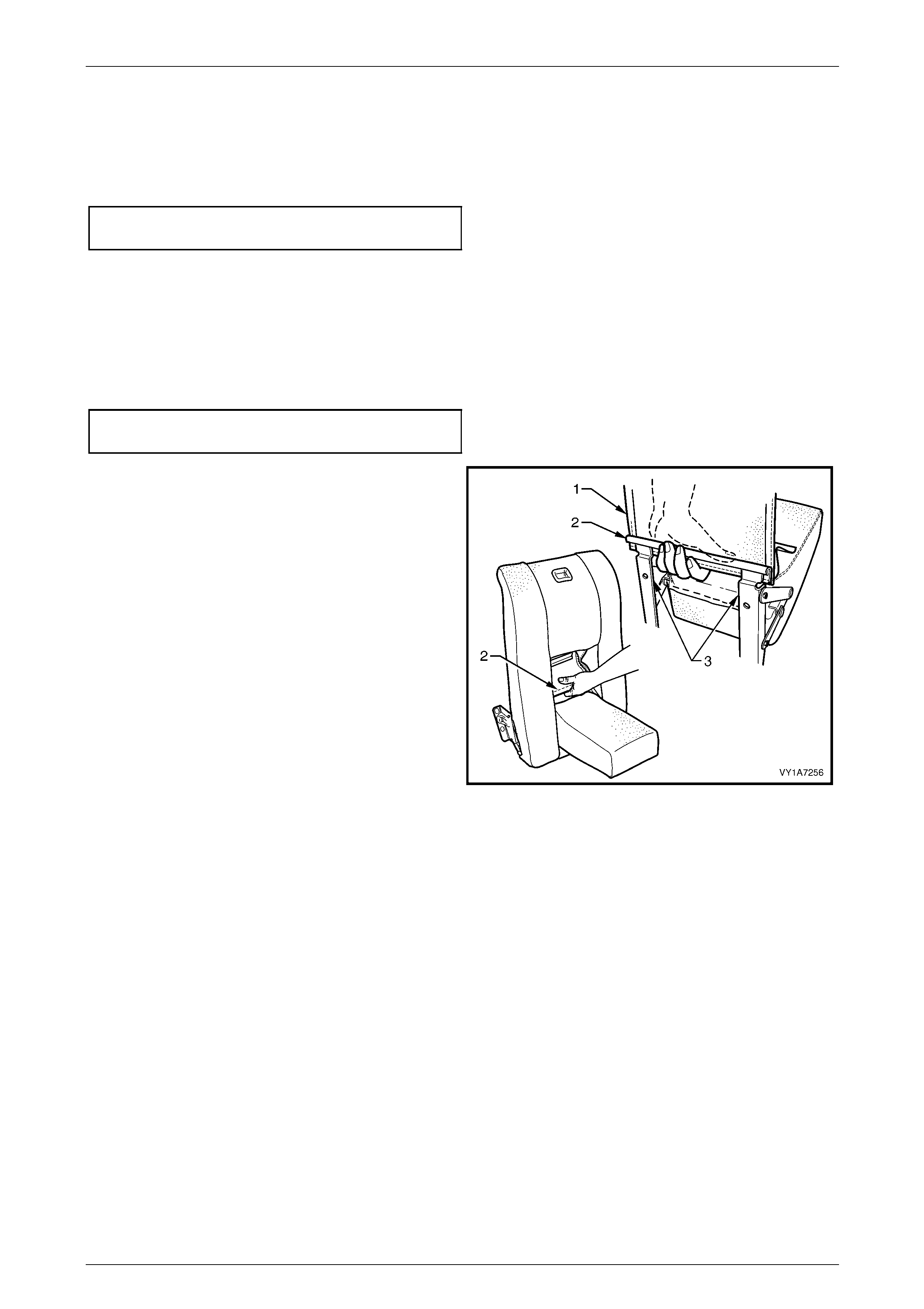
Seat Assemblies Page 1A7A–330
Page 1A7A–330
Reassemble
Assembly of the rear seat-back centre armrest assembly is the reverse of the removal procedure, noting the following:
1 Ensure the armrest assembly hinge is installed before the cover is fitted.
2 Ensure all attaching screws are tightened to the specified torque.
Armrest hinge attaching screw
torque specification...................................7.0 – 10.0 Nm
3 The cover is to be smooth and without creases, before the staples are installed.
Reinstall
Reinstallation of the rear seat -back centre armrest assembly is the reverse of the removal procedure, noting the
following:
1 Ensure a ll attaching screws are tightened to the specifi ed torque.
Armrest hinge assembly attaching
screw torque specification...........................3.5 – 5.0 Nm
2 Refit the armrest trim flap (1) upper J-strip (2) to the
upper part of the hinge bracket (3).
Figure 1A7A – 298
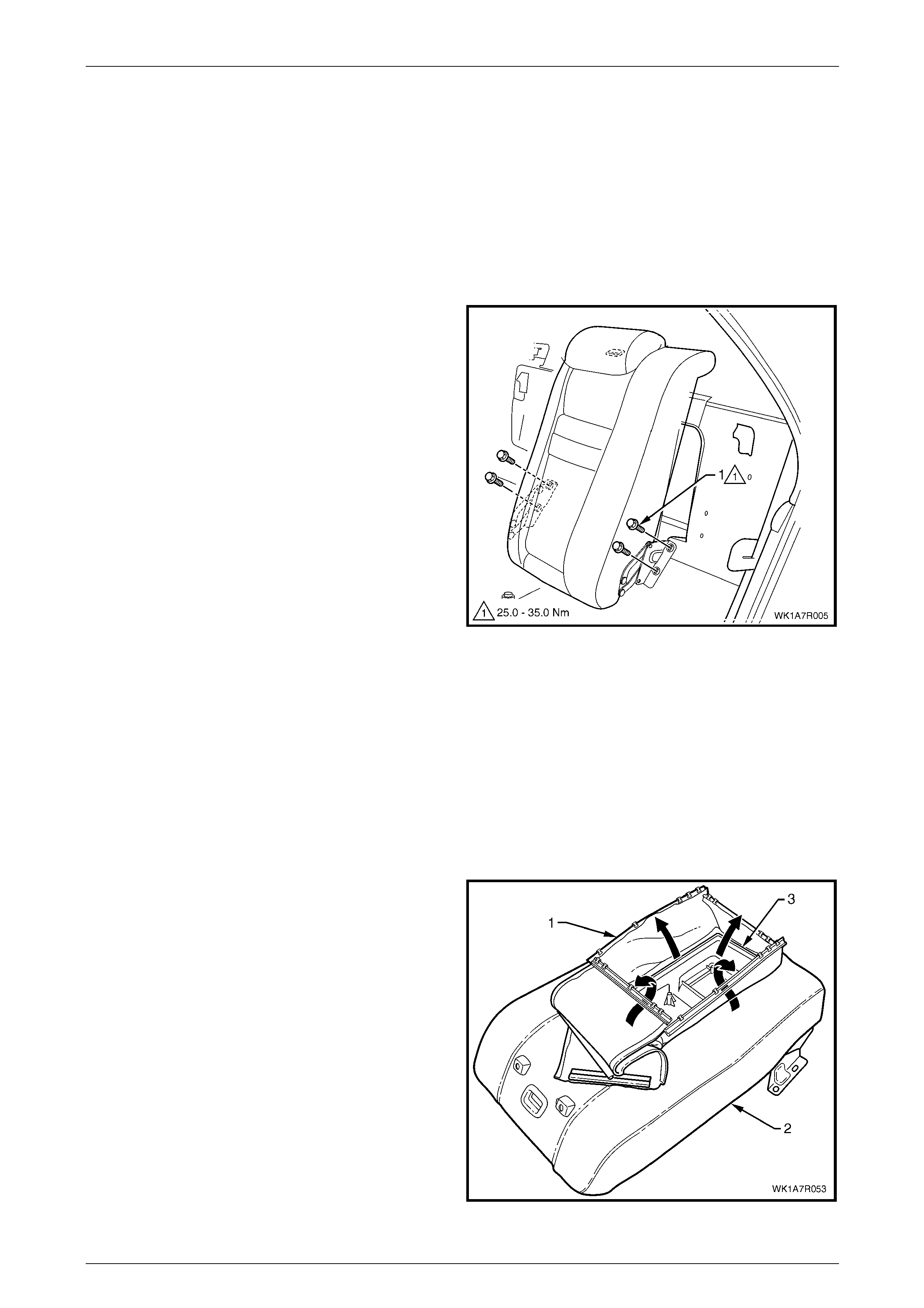
Seat Assemblies Page 1A7A–331
Page 1A7A–331
6.7 Rear Seat-back Centre Assembly
LT Section No. – 14-325
Remove
Although there are phys ical differences bet ween the different types of centre rear seat-back assemblies, the removal and
reinstallation procedures are the same for all.
1 If required, remove the rear seat-back assembl y, refer to 6.4 Rear Seat-back Assembly.
2 Remove the four bolts (1) attaching the rear seat-back
centre assembly to the rear compartment front panel.
3 Unlatch the rear seat-back assembly and remove from
the vehicle.
Figure 1A7A – 299
Disassemble
Pad Assembly, Cover and Head Restraint Sleeves
If required, remove the following:
1 Head restraint, refer to 6.5 Rear Seat-back Centre Head Restraint Assembl y.
2 Rear seat-back centre armrest, refer to 6.6 Rear Seat-back Centre Armrest Assembly.
Remove
1 If fitted with an armrest, pull the four retaining strips (1)
in the centre of the seat-back centre assembly (2), up
and away from the inside of the seat-back tray (3).
Figure 1A7A – 300

Seat Assemblies Page 1A7A–332
Page 1A7A–332
2 On the outer edge of the seat-back centre tray (1),
lever up the retaining strip (2), four places.
Figure 1A7A – 301
3 Remove the four staples (1) each side, attaching the
cover (2) to the seat-back tray (3).
4 Peel the cover away from the seat-back tray.
Figure 1A7A – 302
5 Lever the seat cover material (1) over the release
button (2) and escutcheon assembly (3).
Figure 1A7A – 303
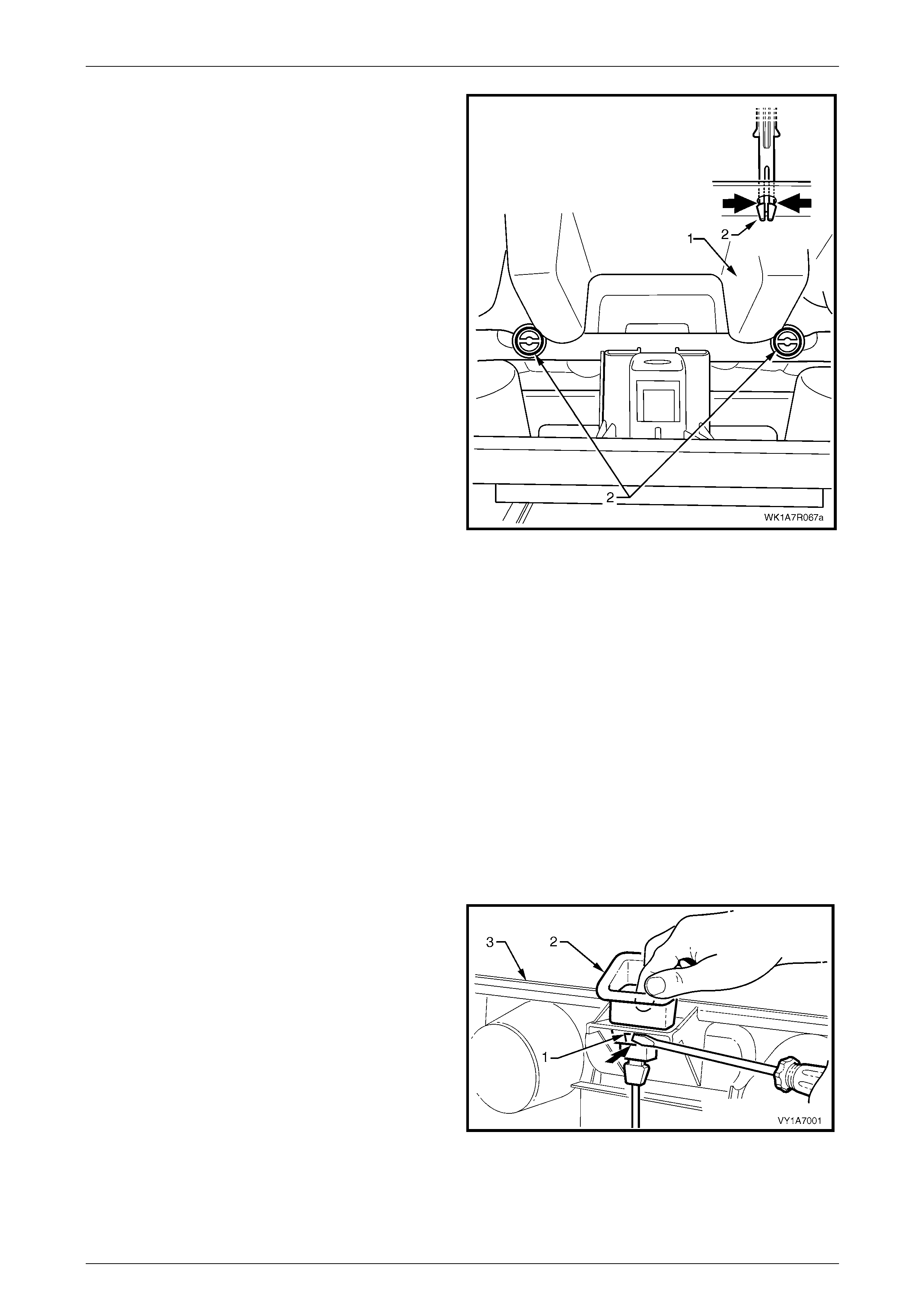
Seat Assemblies Page 1A7A–333
Page 1A7A–333
6 From the back of rear seat-back (1) (foam side), fold
the foam back and squeeze the head restraint sleeve
locating prongs (2) together and remove the sleeve up
and out of the centre seat-back assembly.
7 Remove the cover and pad.
Figure 1A7A – 304
Reinstall
Reinstallation of the rear seat centre back cover and pad assembly is the reverse of the removal proce dure, noting the
following:
1 The cover is to be smooth and without creases before the staples are installed.
2 Ensure all retaining strips are attached properly.
3 When installing the head restraint sleeve, align the locating ribs with the key-way in the seat-back frame.
NOTE
Ensure the sleeve with the height adj uster lock is
installed on the side that corresponds to the
notches in the head restraint shaft.
Rear Seat-back Centre Release Button
Remove
If required, remove the rear seat-back cover, refer to Pad Assembly, Cover and Hea d Restraint Sleeves.
1 Using a screwdriver, depress the two tangs (1) on the
front and rear of the release button (2).
2 Pull the release button from the rear seat-back
centre (3).
Figure 1A7A – 305
Reinstall
Push the release button into the rear seat-back centre assembly, until the button clicks home.
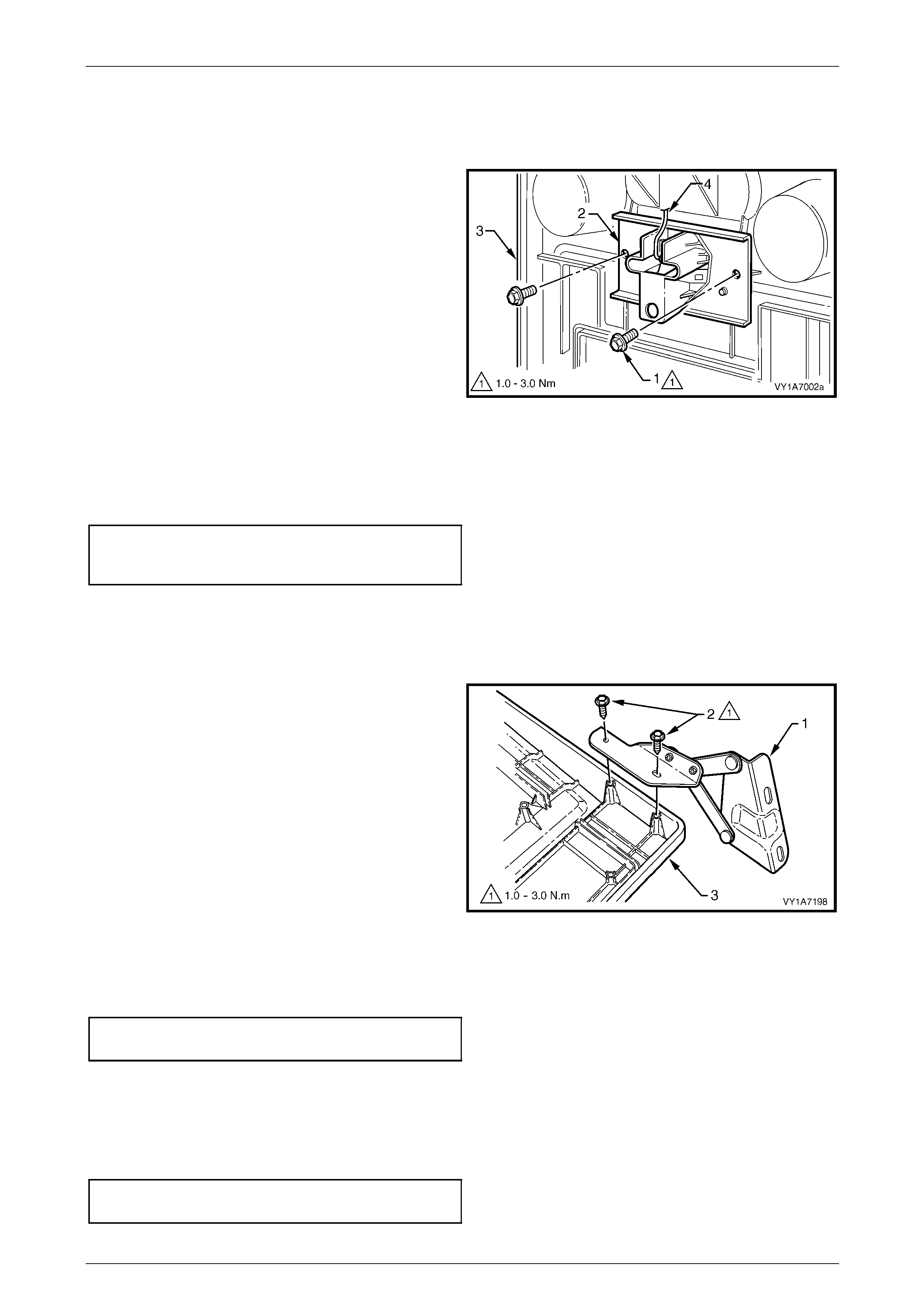
Seat Assemblies Page 1A7A–334
Page 1A7A–334
Rear Seat-back Centre Lock Actuator
Remove
If required, remove the rear seat-back cover, refer to Pad Assembly, Cover and Hea d Restraint Sleeves.
1 Remove the two screws (1) securing the lock
actuator (2) to the back tray (3) and remove lock
actuator.
2 Disengage the release button rod (4) from the lock
actuator.
Figure 1A7A – 306
Reinstall
Reinstallation of the rear seat-back centre lock actuator is the reverse of the removal proc edure noting the following:
1 Ensure the button assembly and lock actuator rod are correctly engaged.
2 Ensure all attaching screws are tightened to the specified torque.
Rear seat-back centre lock
actuator attaching screw
torque specification.....................................1.0 – 3.0 Nm
Rear Seat-back Centre Hinge
Remove
If required, remove the rear seat-back cover, refer to Pad Assembly, Cover and Hea d Restraint Sleeves.
1 Remove the two screws (2) securing the hinge (1) to
the rear seat-back centre tray assembly (3) and
remove the hinge.
2 If required, repeat for the opposite hinge.
Figure 1A7A – 307
Reinstall
Reinstallation of the rear seat-back centre hinge is the reverse of the removal procedure, noting the following:
Ensure all attaching screws are tightened to the specified torque.
Rear seat-back centre hinge
attaching screw torque specification...........1.0 – 3.0 Nm
Reinstall
Reinstallation of the rear seat-back assembly is the reverse of the removal procedure, noting the following:
1 Ensure the rear seat-back assembly is positione d centrally and there is no bind ing of the latch assembly.
2 Tighten all attaching bolts to the spec ified torque.
Rear seat-back centre assembly
attaching bolt torque specification...........25.0 – 35.0 Nm
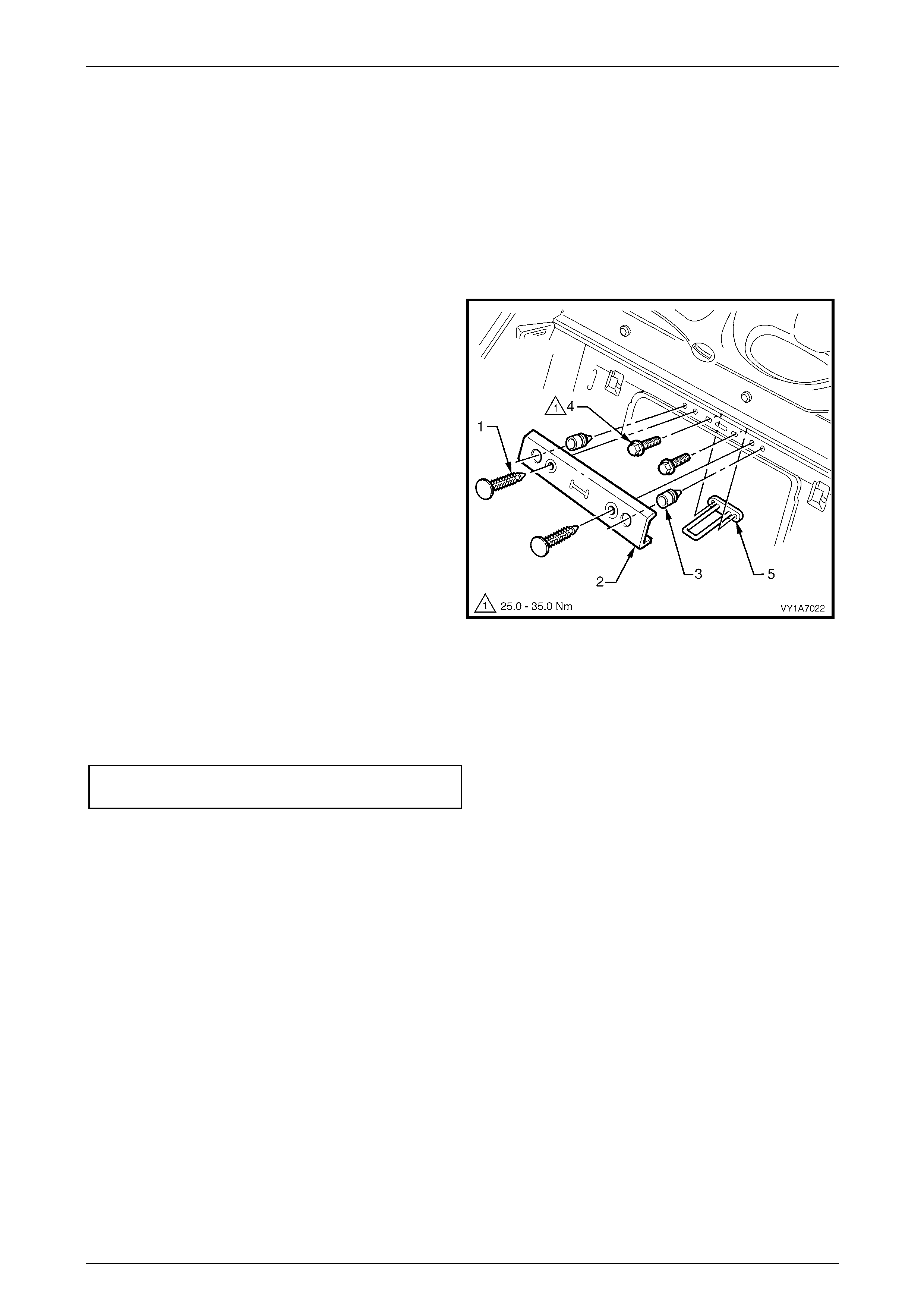
Seat Assemblies Page 1A7A–335
Page 1A7A–335
6.8 Rear Seat-back Centre Lock Striker
LT Section No. – 14-350
Remove
1 If required, remove the following:
a Remove the rear seat cushion assembly, refer to 6.2 Rear Seat Cushion Assembly.
b Remove the rear seat-back assembly, refer to 6.4 Rear Seat-back Assembl y.
2 Prise the two retaining clips ( 1) securing the rear
seat-back cover (2) to the rear compartment front
panel and remove the cover.
3 If required, remove the two bump stops (3) from the
rear compartment front panel.
4 Remove the two screws (4) securing the striker (5) to
the rear panel and remove the striker.
Figure 1A7A – 308
Reinstall
Reinstallation of the rear seat lock striker is the reverse of the removal procedure, noting the following:
Ensure all attaching screws are tightened to the specified torque.
Rear seat-back centre lock striker
attaching screw torque specification.......25.0 – 35.0 Nm

Seat Assemblies Page 1A7A–336
Page 1A7A–336
7 Torque Wrench Specifications
Front Seat
Fire Extinguisher Mounting Bracket Attaching Screw................15.0 – 20.0 Nm
Front Seat Assembly Attaching Screw......................................35.0 – 50.0 Nm
Front Seat Outer Front Cover Attaching Screw.............................1.0 – 3.0 Nm
Front Seat Adjustment Switch Attaching Screw ............................1.0 – 3.0 Nm
Memory Position Switch Cover Attaching Screw...........................1.0 – 3.0 Nm
Front Seat Outer Side Cover Attaching Screw..............................1.0 – 3.0 Nm
Front Seat Inner Side Cover Attaching Screw...............................1.0 – 3.0 Nm
Front Seat-back Map Pocket Attaching Screw..............................1.0 – 3.0 Nm
Rear Seat Entertainment Screen Pivot Hinge Attaching Screw.....1.0 – 3.0 Nm
Rear Seat Entertainment Screen Attaching Screw........................1.0 – 3.0 Nm
Rear Seat Entertainment Circuit Board Attaching Screw...............1.0 – 3.0 Nm
Rear Seat Entertainment Head Rest Escutcheo n Attaching
Screw ............................................................................................1.0 – 3.0 Nm
Lumbar Support Knob Attaching Screw.........................................2.0 – 5.0 Nm
Side Impact Airbag Assembly Attaching Nut.................................5.0 – 6.0 Nm
Front Seat Dummy Block Insert Assembly Attaching Nut..............5.0 – 6.0 Nm
Active Head Restraint Frame Assembly Attaching Nut .................3.0 – 5.0 Nm
Front Seat-back Frame Assembly Attaching Screw..................30.0 – 45.0 Nm
Track and Height Adjust Assembly Attaching Nut.....................24.0 – 32.0 Nm
Rear Seat
Rear Seat-back Assembly Attaching Bolt..................................25.0 – 35.0 Nm
Rear Seat-back Centre Armrest Hinge Attaching Screw...............1.0 – 3.0 Nm
Rear Seat-back Centre Armrest Lid Attaching Screw....................1.0 – 3.0 Nm
Rear Seat-back Centre Armrest Lid Latch Attaching Screw..........1.0 – 3.0 Nm
Cup Holder Housing Attaching Screw ...........................................1.0 – 3.0 Nm
Rear Seat-back Centre Armrest Lid Hinge Attaching Screw .........1.0 – 3.0 Nm
Armrest Hinge Attaching Screw...................................................7.0 – 10.0 Nm
Armrest Hinge Assembly Attaching Screw....................................3.5 – 5.0 Nm
Rear Seat-back Centre Lock Actuator Attaching Screw................1.0 – 3.0 Nm
Rear Seat-back Centre Hinge Attaching Screw.............................1.0 – 3.0 Nm
Rear Seat-back Centre Assembly Attaching Bolt......................25.0 – 35.0 Nm
Rear Seat-back Centre Lock Striker Attaching Screw...............25.0 – 35.0 Nm