
Headlining and Int eri or Tri m Page 1A8–1
23–OCT–2002 Page 1A8–1
Section 1A8
Headlining and Interior Trim
ATTENTION
Before performing any Service Operation or other procedure described in this Section, refer to Section 00
WARNINGS, CAUTIONS AND NOTES for correct workshop practices with regard to safety and/or property
damage.
1 General Information............................................................................................................................... 2
2 Service Operations................................................................................................................................ 3
2.1 Outer Rocker Panel Cover Assembly...................................................................................................................5
Remove ...................................................................................................................................................................5
Reinstall..................................................................................................................................................................5
2.2 Side Sill Trim and Plate .........................................................................................................................................6
Remove ...................................................................................................................................................................6
Reinstall..................................................................................................................................................................6
2.3 Body Lock Pillar Low er Trim.................................................................................................................................7
Remove ...................................................................................................................................................................7
Disassemble...........................................................................................................................................................8
Reinstall..................................................................................................................................................................8
2.4 Body Lock Pillar Garnish.......................................................................................................................................9
Remove ...................................................................................................................................................................9
Reinstall..................................................................................................................................................................9
2.5 Rear Window Trim Panel Assembly...................................................................................................................10
Remove .................................................................................................................................................................10
Disassemble.........................................................................................................................................................11
Assemble ..............................................................................................................................................................11
Reinstall................................................................................................................................................................11
2.6 Headlining Assembly...........................................................................................................................................12
Remove .................................................................................................................................................................13
Reinstall................................................................................................................................................................15
2.7 Quarter Inner Rear Side Carpet...........................................................................................................................16
Remove .................................................................................................................................................................16
Reinstall................................................................................................................................................................17
2.8 Spare Wheel Well Container................................................................................................................................18
Remove .................................................................................................................................................................18
Reinstall................................................................................................................................................................18
3 Specifications....................................................................................................................................... 19
3.1 Trim Clearances ...................................................................................................................................................19
4 Torque Wrench Specifications........................................................................................................... 20

Headlining and Int eri or Tri m Page 1A8–2
23–OCT–2002 Page 1A8–2
1 General Information
With the following exceptions, MY 2004 WK Series Headlining and Interior Trim information carries over from MY 2003
VY Series vehicles. For information not contained within this Section, refer to Section 1A8 Headlining And Interior Trim
in the MY 2003 VY and V2 Series Service Information.
• Outer rocker panel cover assembly
• Side sill trim and plate
• Body lock pillar lower trim
• Body lock pillar garnish
• Rear window trim panel assembly
• Headlining assembly
• Quarter inner rear side carpet
• Spare wheel container
• Trim clearances
The headlining assembly is a one piece moulded type that is attached to the roof using an industrial strength Velcro.
Three variations are available:
• Level 1 vehicles without sunroof. These vehicles have a central dome lamp.
• All other vehicles without an on-line fitted sunroof. These vehicles have a roof console fitted near the front of the
headlining. The roof console incorporates the dome lamp and a sunglasses holder and carries-over from MY 2003
VY Series vehicles.
• All vehicles with an on-line fitted sunroof. The headlining for these vehicles is shaped for the sunroof aperture and
also has the roof console.
In the rear compartment, the right-hand quarter inner rear side carpet incorporates a power socket in one of two different
locations depending on the model Level of the vehicle. For Level 4 the power socket is supported by a bracket off the
sheetmetal.
For Level 5 vehicles the power socket is attached to the top of the Premium Sound amplifier. The Level 5 right-hand
quarter inner rear side carpet is a different shape to allow for the Premium Sound amplifier that is fitted behind the
carpet in the rear right-hand corner of the rear compartment.
The left-hand side quarter inner rear side carpet is the same for all Levels.
The interior trim is the same for left-hand and right-hand drive models, except for the fuel filler door release and the
hood release lever.
NOTE
When working on the body interior trim, clean
hands are essential and protective covering must
be placed over the interior trim.
Headlining and Int eri or Tri m Page 1A8–3
23–OCT–2002 Page 1A8–3
2 Service Operations
NOTE
The following chart is included to assist with the
identification of the components and where their
service procedures are located.
For the service procedures of the rear compartment lid carpet, refer to Section 1A4, 3.2 Rear Compartment Lid Carpet.
For the service procedures of the front and rear door trim panel assemblies for Levels 1 to 4 vehicles, refer to Section
1A5, 2.6 Front Door Trim Panel Assembly and 3.6 Rear Door Trim Panel Assembly in the MY 2003 VY and V2 Series
Service Information.
For the service procedures of the front and rear door trim panel assemblies for Level 5 vehicles, refer to Section 1A5,
2.1 Front Door Trim Panel Assembly and 2.3 Rear Door Trim Panel Assembly.
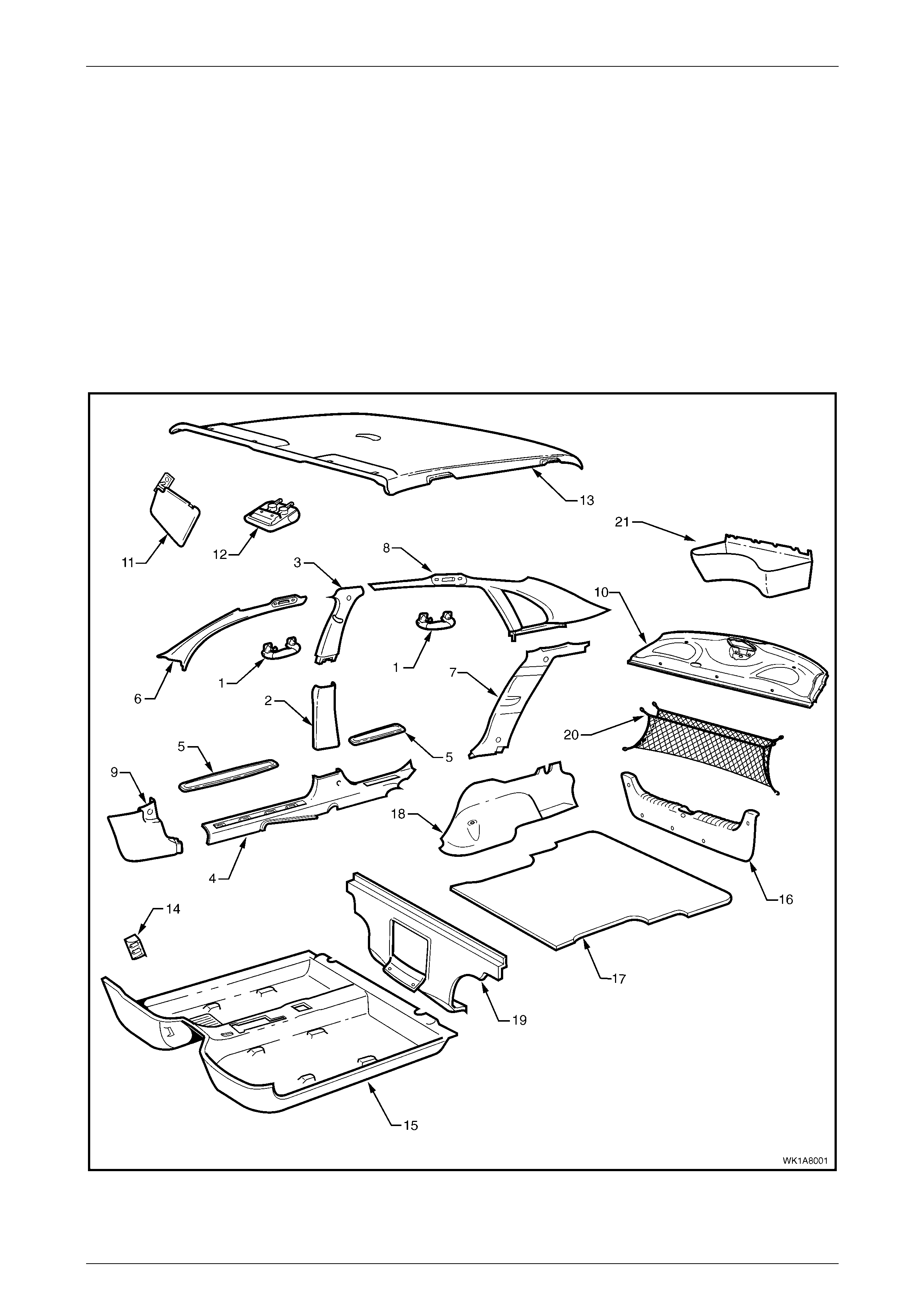
Figure 1A8 – 1

Headlining and Int eri or Tri m Page 1A8–4
23–OCT–2002 Page 1A8–4
Legend
1 Assist Handle, ref er to Sec tion 1A8, 2.1 ASSIST HANDLE
in the MY 2003 VY and V2 Series Service Inform at i on.
2 Centre Pillar Lower Trim, refer to Section 1A8, 2.2
CENTRE PI LLAR LOW E R TRIM in the MY 2003 VY and
V2 Series Service Inf ormation.
3 Centre Pillar Upper Trim, refer to Section 1A8, 2.3
CENTRE PILLAR UPPER TRIM in the MY 2003 VY and V2
Series S e rvi ce Information.
4 Side Sill Trim, refer to 2. 2 SIDE SILL TRIM AND PLATE.
5 Side Sill Trim Plate, refer to 2.2 SIDE SILL TRIM AND
PLATE.
6 Windshield Si de Garni sh, refer to Section 1A8, 2.5
WINDSHIE LD SIDE GARNIS H i n the MY 2003 VY and V2
Series S e rvi ce Information.
7 Body Lock Pillar Lower Trim, refer to 2.3 BODY LOCK
PILLAR LOWER TRIM.
8 Body Lock Pillar Garnish, refer to 2.4 BODY LOCK PILLAR
GARNISH.
9 Hinge Pillar Trim A ssembly, refer t o S ec tion 1A8, 2.8
HINGE PILLAR TRIM ASSEMBLY in t he MY 2003 VY and
V2 Series Service Inf ormation.
10 Rear Window Trim Panel, refer to 2.5 REAR WINDOW
TRIM PANEL ASSEMBLY.
11 Sunshade Assembly, refer to Secti on 1A 8, 2.10
SUNSHADE ASSEMBLY in the MY 2003 VY and V2 Series
Service Informati on.
12 Roof Console, refer to Secti on 1A 8, 2.11 ROOF CONSOLE
in the MY 2003 VY and V2 Series Service Inform at i on.
13 Headlining Assembly, refer to 2.6 HEADLI NING
ASSEMBLY
14 Driver Footrest , refer to Section 1A8, 2.13 DRIVER
FOOTREST in t he MY 2003 VY and V2 Series S ervi ce
Information.
15 Front Floor Carpet A ssembly, refer to Section 1A8, 2.14
FRONT FLOOR CARPET ASSEMBLY in t he MY 2003 VY
and V2 Series Service Information.
16 Rear End Trim Panel, refer to S ection 1A8, 2.15 REAR
END TRIM PANE L i n the MY 2003 VY and V2 Series
Service Informati on.
17 Rear Compart ment Floor Carpet Assembly, refer to Secti on
1A8, 2.16 RE A R COMPA RTMENT FLOOR CARP ET
ASSEMBLY in the MY 2003 VY and V2 Series Service
Information.
18 Quarter Inner Rear Si de Carpet, refer to 2.7 QUA RTE R
INNER RE AR SIDE CARPET.
19 Rear Seat Back Panel Carpet, refer to Secti on 1A 8, 2.18
REAR SEAT BACK PANEL CA RPET in the MY 2003 VY
and V2 Series Service Information.
20 Convenience Net, refer to Section 1A8, 2.19
CONVENIE NCE NET in the MY 2003 VY and V 2 Series
Service Informati on.
21 Spare Wheel Well Container, refer to 2. 8 SPARE WHEEL
WELL CONTAINER.
Headlining and Int eri or Tri m Page 1A8–5
23–OCT–2002 Page 1A8–5
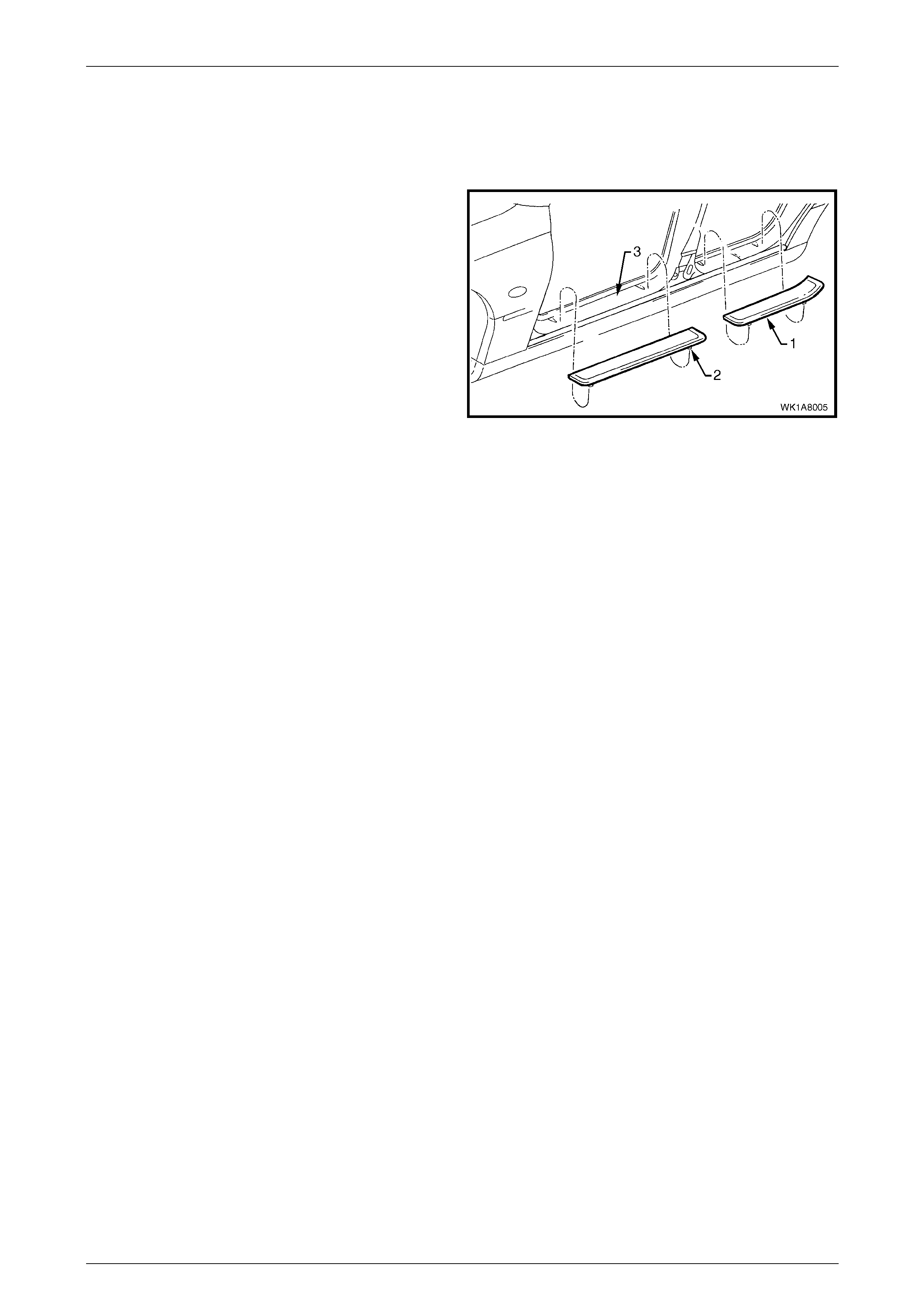
2.1 Outer Rocker Panel Cover As sembly
Remove
1 Protect the paint and bodywork with tape or a rag.
2 To assist removal, warm the outer rocker panel cover
assembly (1) with a heat-lamp or heat-gun to soften
the adhesive.
NOTE
Each outer rocker panel cover has two locating
tabs (2) that must not be cut if it is to be reused.
3 Using a knife or paint scraper, carefully remove the
outer rocker panel cover from the door opening frame
(3), cutting the double-sided tape.
4 Remove any remaining double-sided tape as required.
Figure 1A8 – 2
Reinstall
1 If reinstalling the existing cover, remove the used double-sided tape and clean the surface with a wax and grease
remover such as Prepsol or equivalent. Apply new polyethylene double-sided tape such as 3M 4428 or equivalent.
2 Clean the surface of the outer rocker panel assembly with a wax and grease remover such as Prepsol or
equivalent.
3 Remove the backing paper from the double-sided tape.
4 Align the tabs on the outer rocker panel cover assembly with the holes in the door opening frame .
5 Affix the cover and press firmly over the entire surface for at least 10 seconds to ensure sound adhesion.
Headlining and Int eri or Tri m Page 1A8–6
23–OCT–2002 Page 1A8–6
2.2 Side Sill Trim and Plate
LT Section No. – 14-100
Remove the centre pillar lower trim, refer to Section 1A8, 2.2 Centre Pillar Lower Trim in the MY 2003 VY and V2 Series
Service Information.
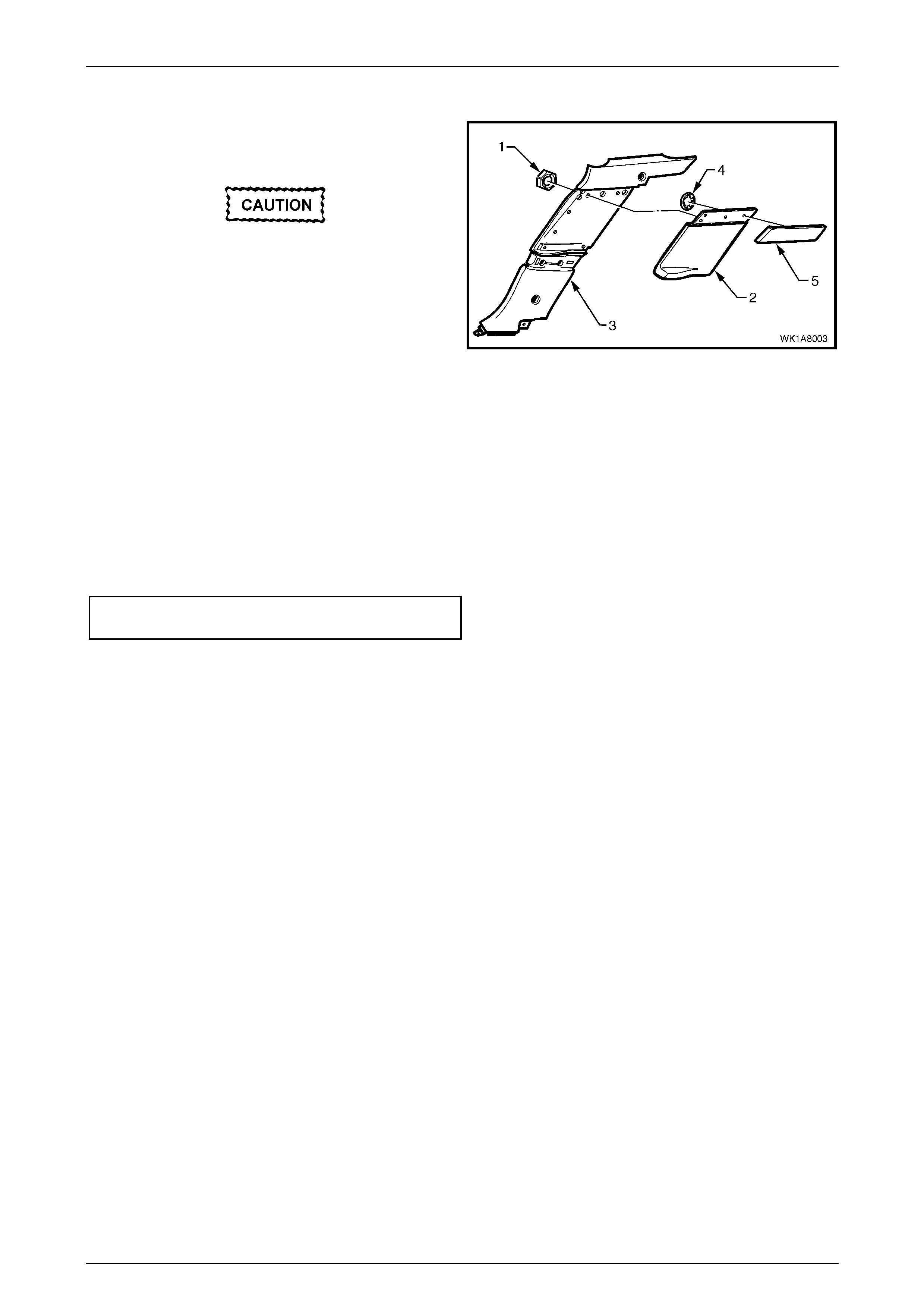
Remove
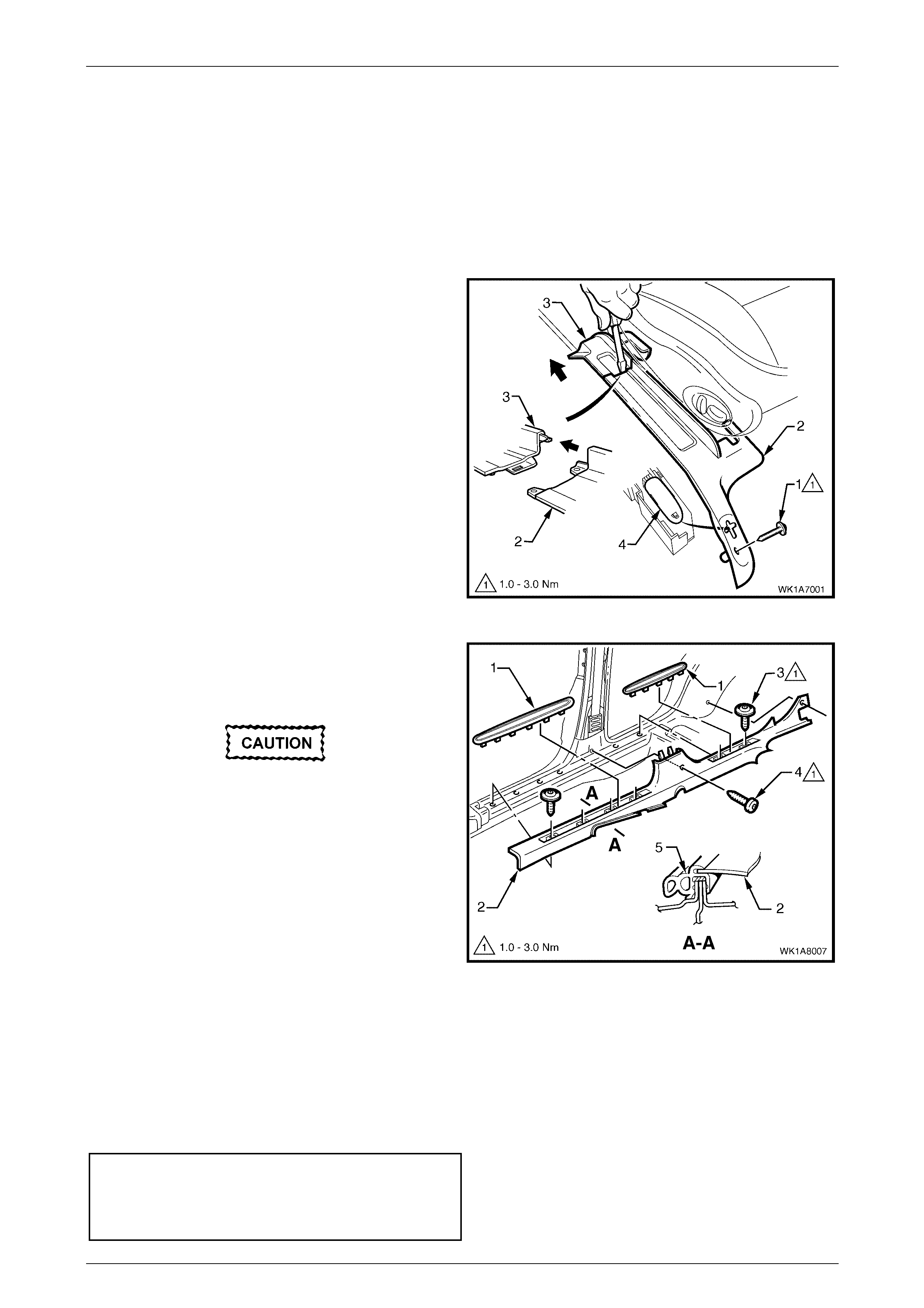
1 For the driver's side on right-hand drive vehicles,
remove the front attaching screw (1) from the seat
adjuster outer front cover (2).
2 Using a small screwdriver, push in the centre of the
join to separate the front cover and the front seat
outer lower rear cover (3).
3 Unclip the covers from the seat track, and disengage
from the side sill trim.
4 Pull the covers apart and remove the rear cover.
5 For the driver’s side on right hand drive vehicles, slide
the front cover over the fuel filler door release lever (4)
and remove.
Figure 1A8 – 3
6 Carefully lever the front and rear side sill trim plates
(1) from the side sill trim (2), starting at the front of
each plate and moving rearwards, revealing the
attaching screws.
Care must be taken not to snap the sill trim
plates.
7 Remove the six Torx head screws (3) from the side sill
trim, four in the front door opening and two in the rear
door opening.
8 Remove the Torx head screw (4), one place each,
from the side sill trim to the centre pillar and the body
lock pillar lower trim.
9 Remove the side sill trim through the front door
opening, by lifting the front and sliding the rear out
from under the rear seat cushion.
Figure 1A8 – 4
Reinstall
Reinstallation of the side sill trim and the seat adjuster outer front cover is the reverse of the removal, noting the
following:
1 Ensure the outer edge of the side sill trim engages the door opening weatherstrip (5), refer Figure 1A8 – 4
2 Tighten all fasteners to the correct torque specification.
Seat adjuster outer front cover attaching
screw torque specification.........................1.0 – 3.0 N.m
Side sill trim attaching screw torque
specification ..............................................1.0 – 3.0 N.m
Headlining and Int eri or Tri m Page 1A8–7
23–OCT–2002 Page 1A8–7
2.3 Body Lock Pillar Lower Trim
LT Section No. – 14-120
1 Remove the side sill trim and plate, refer to 2.2 Side Sill Trim And Plate.
2 Remove the rear seat cushion, refer to Section 1A7 Seat Assemblies.
3 Remove the rear seat back, refer to Section 1A7 Seat Assemblies.
4 Remove the rear lower seat belt bolt, refer to Section12M Occupant Protection System.
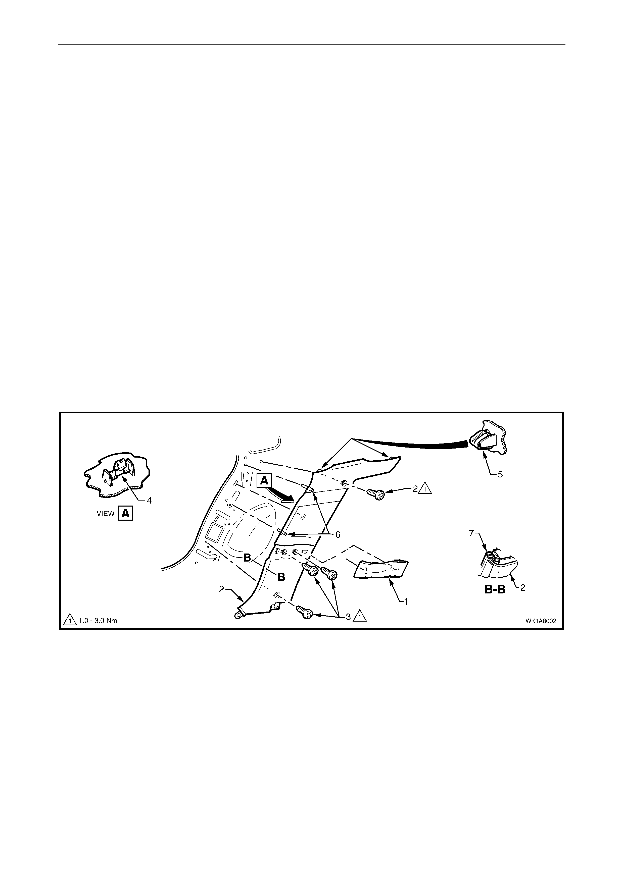
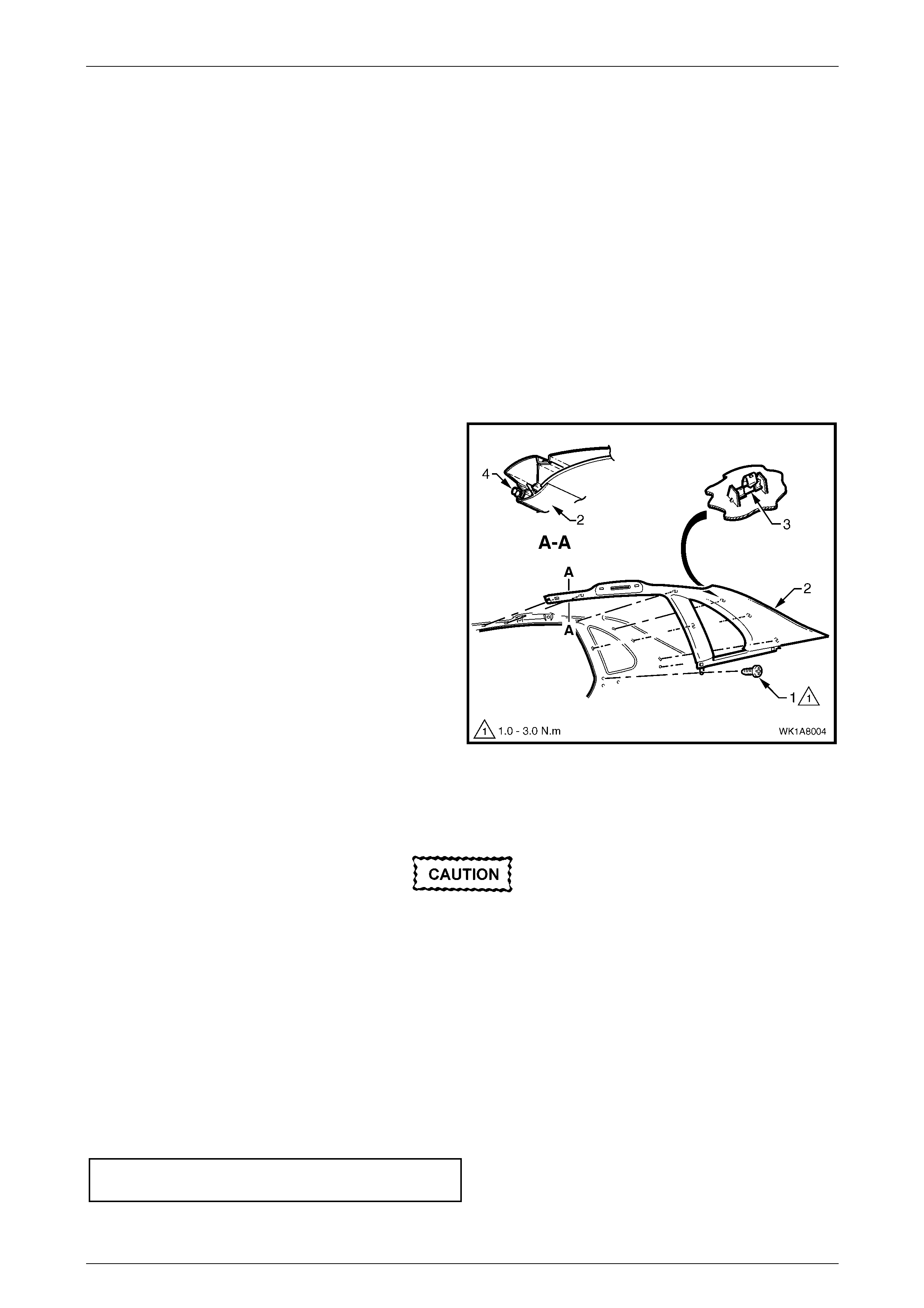
Remove
1 Remove the cap assembly (1) by prising it to release the clips attaching it to the body lock pillar lower trim (2),
refer to Figure 1A8 – 5.
2 Remove the four screws (3) attaching the body lock pillar lower trim to the body lock pillar.
3 Lift the garnish from the bottom gently to unclip the retainer (4) in the centre.
4 Pull the body lock pillar lower trim off the body lock pillar, unclipping the two retainers (5) at the top of the garnish.
NOTE
When removing the body lock pillar lower trim,
ensure care is taken not to damage the two
locating pins (6).
5 Remove the garnish, taking care not to damage the locating pins.
Figure 1A8 – 5
Legend
1 Cap Assembly
2 Screws (4 plac es)
3 Centre Retaini ng Cl i p
4 Top Retaining Cli ps (2 places)
5 Locating Pins
6 Door Seal
7 Body Lock Pillar Lower Trim
Headlining and Int eri or Tri m Page 1A8–8
23–OCT–2002 Page 1A8–8
Disassemble
1 Remove the insulation from the back of the garnish,
taking care not to tear it.
Take care when removing speed nuts as it is
very easy to break the lug during removal.
2 Remove the six hex speed nuts (1) that are attaching
the insert (2) to the body lock pillar lower trim (3) and
remove the insert.
4 Where fitted remove the four round speed nuts (4)
retaining the applique (5).
Figure 1A8 – 6
Reinstall
Reinstallation of the body lock pillar lower trim is the reverse of the removal, noting the following:
1 Ensure the body lock pillar lower trim is fully engaged with the side sill trim plate.
2 Ensure the body lock pillar lower trim locating pins are aligned with the holes in the inner panel.
3 Ensure the outer edge of the body lock pillar lower trim engages the door opening weatherstrip (7), refer to Figure
1A8 – 5.
4 Tighten all fasteners to the correct torque specification.
Body lock pillar lower trim attaching
screw torque specification.........................1.0 – 3.0 N.m
Headlining and Int eri or Tri m Page 1A8–9
23–OCT–2002 Page 1A8–9
2.4 Body Lock Pillar Garnish
LT Section No. – 14-120
1 Remove the body lock pillar lower trim, refer to 2.3 Body Lock Pillar Lower Trim.
2 Remove the rear assist handle, refer to Section 1A8, 2.1 Assist Handle in the MY 2003 VY and V2 Series Service
Information.
3 If fitted, remove the roof rail courtesy lamp, refer to Section 12B, 3.15 Roof Rail Courtesy And Reading Lamp
Assembly in the MY 2003 VY and V2 Series Service Information.
4 Partially remove the centre pillar upper trim by removing the upper attaching screw, refer to Section 1A8,
2.3 Centre Pillar Upper Trim Assembly in the MY 2003 VY and V2 Series Service Information.
5 Remove the rear seat cushion and seat back, refer to Section 1A7 Seat Assemblies.
Remove
1 Remove the screw (1).
2 Pull the front edge of the body lock pillar garnish (2)
away from the body lock pillar and working rearwards,
disengage the seven retaining clips (3).
3 Remove the body lock pillar garnish.
Figure 1A8 – 7
Reinstall
Take care when reinstalling the body lock
pillar garnish not to crush or dent the sunroof
drain tubes.
Reinstallation of the body lock pillar garnish is the reverse of the removal, noting the following:
1 Ensure the body lock pillar garnish is fully engaged with the body lock pillar lower trim.
2 Ensure the body lock pillar garnish is fully engaged with the centre pillar upper trim assembly.
3 Ensure the body lock pillar garnish locating pin is aligned with the hole in the inner panel.
4 Ensure the outer edge of the body lock pillar garnish engages the door opening weatherstrip (4), refer to Figure
1A8 – 7.
5 Tighten all fasteners to the correct torque specification.
Body lock pillar garnish attaching screw
torque specification...................................1.0 – 3.0 N.m
Headlining and Int eri or Tri m Page 1A8–10
23–OCT–2002 Page 1A8–10
2.5 Rear Window Trim Panel Assembly
LT Section No. – 14-460
1 Remove the rear seat cushion and seat back, refer to Section 1A7 Seat Assemblies.
2 Remove the body lock pillar garnish, refer to 2.4 Body Lock Pillar Garnish.
3 Remove the lower centre seat belt bolt, refer to Section12M, Occupant Protection System.
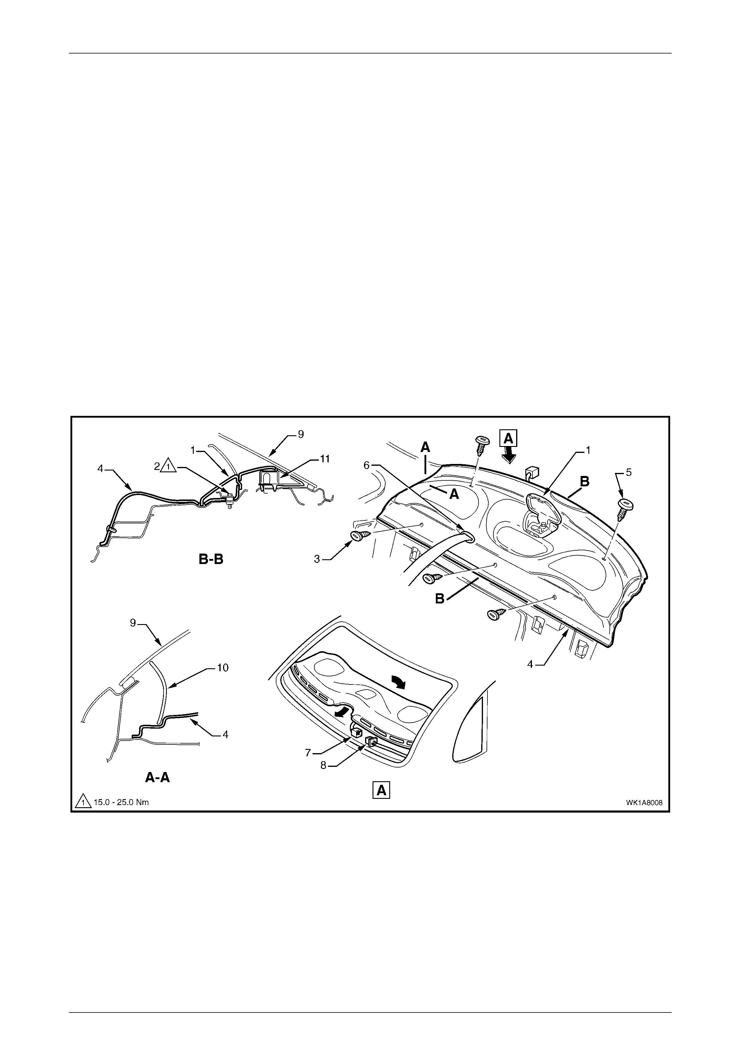
Remove
1 Open the lid (1) to the child restraint fitting and unbolt the child seat anchor (2), refer to Figure 1A8 – 8.
2 Remove the three retainers (3) attaching the forward edge of the rear window trim panel assembly (4).
3 Remove the two retainers (5) attaching the upper surface of the rear window trim panel assembly.
4 Lift the front edge of the rear window trim panel assembly and remove the seat belt escutcheon (6) from the parcel
shelf. Feed centre seat belt lower anchor, buckle and escutcheon through the seat belt opening in the parcel
shelf.
5 Where fitted, disconnect rear headphone jack connector (7) from the body wiring harness (8).
6 Remove the rear window trim panel assembly.
Figure 1A8 – 8
Legend
1 Child Seat Anchor
2 Child Seat Anchor Screw
3 Forward Edge Rear W i ndow Trim Panel Retainers
4 Rear Window Trim Panel
5 Upper Edge Rear Window Trim Panel Retainers
6 Seat Bel t Escutc heon
7 Headphone Jack Connector
8 Body Wiring Harness Connector
9 Rear Window Glass
10 Upper Body Lock Pillar Trim
11 High Mount Stop Lamp
Headlining and Int eri or Tri m Page 1A8–11
23–OCT–2002 Page 1A8–11
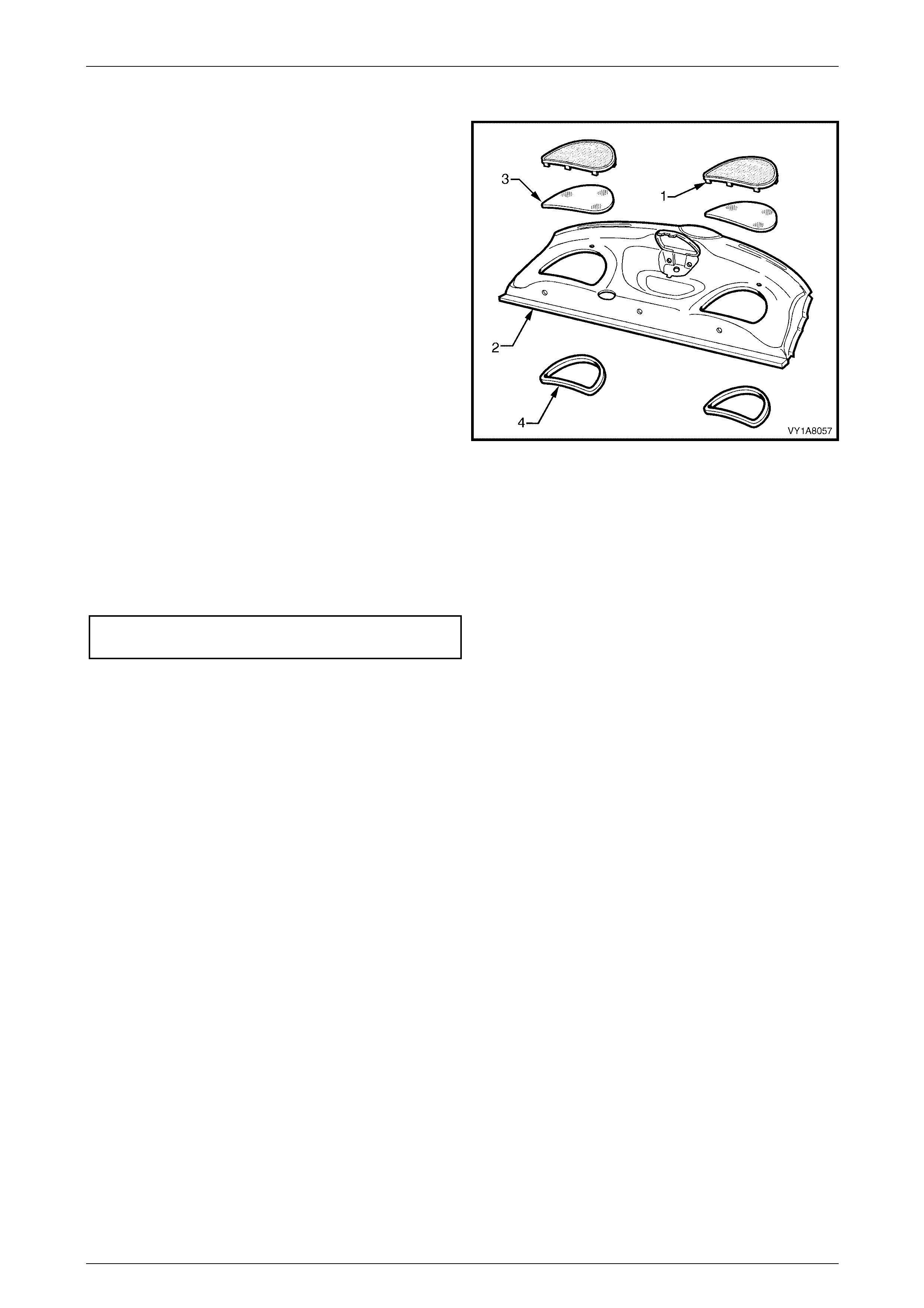
Disassemble
1 Bend the nine speaker grille tabs (1) to a vertical
position and remove from the rear window trim panel
assembly (2).
2 Remove the dust seal (3) from the speaker grille.
3 Remove the speaker seal (4) from the rear window
trim panel assembly.
4 Remove the child restraint cover by pushing the part
rearward and disengaging the front retainers.
Assemble
Reinstallation of the rear window trim panel speaker grille is
the reverse of the removal, noting the following:
1 Bend the nine speaker grille tabs to a horizontal
position to retain the speaker grille.
Figure 1A8 – 9
Reinstall
Reinstallation of the rear window trim panel assembly is the reverse of the removal, noting the following:
1 Where fitted, ensure the speaker seals do not foul on the speaker assemblies.
2 Tighten the child seat anchor screw to the correct torque specification.
Child seat anchor attaching screw
torque specification...............................15.0 – 25.0 N.m

Headlining and Int eri or Tri m Page 1A8–12
23–OCT–2002 Page 1A8–12
2.6 Headlining Assembly
LT Section No. – 14-150
Disconnection of the battery affects certain
vehicle electronic systems. Refer to
Section 00, 6 Battery Disconnection
Procedures before disconnecting the battery.
NOTE
The following procedure can be used for vehicles
fitted with an online sunroof assembly. W here a
Holden By Design sunroof is fitted, a new
headlining has been created using pieces of the
original headlining and a new piece of cloth. The
headlining is then installed with adhesive.
Removal may damage the headlining and
extreme car is required.
1 Disconnect the battery ground cable.
2 Place protective covering over both front seats and the interior trim.
3 Remove the rear seat cushion and rear seat, refer to Section 1A7, Seat Assemblies.
4 Remove assist handles, refer to Section 1A8, 2.1 Assist Handle in the MY 2003 VY and V2 Series Service
Information.
5 If fitted, remove the roof rail courtesy lamp, refer to Section 12B, 3.15 Roof Rail Courtesy And Reading Lamp
Assembly in the MY 2003 VY and V2 Series Service Information.
6 Partially remove the centre pillar upper trim by removing the upper attaching screw, refer to Section 1A8,
2.3 Centre Pillar Upper Trim Assembly in the MY 2003 VY and V2 Series Service Information.
7 Remove the windshield side garnish, refer to Section 1A8, 2.5 Windshield Side Garnish in the MY 2003 VY and V2
Series Service Information.
8 Remove the body lock pillar garnish, refer to 2.4 Body Lock Pillar Garnish.
9 Remove the sunshade assembly, refer to Section 1A8, 2.10 Sunshade Assembly in the MY 2003 VY and V2
Series Service Information.
10 Remove the roof console, if fitted, refer to Section 1A8, 2.11 Roof Console in the MY 2003 VY and V2 Series
Service Information.
11 Remove the dome lamp, if fitted, refer to Section 12B, 3.8 Dome Lamp Assembly.
Headlining and Int eri or Tri m Page 1A8–13
23–OCT–2002 Page 1A8–13
Remove
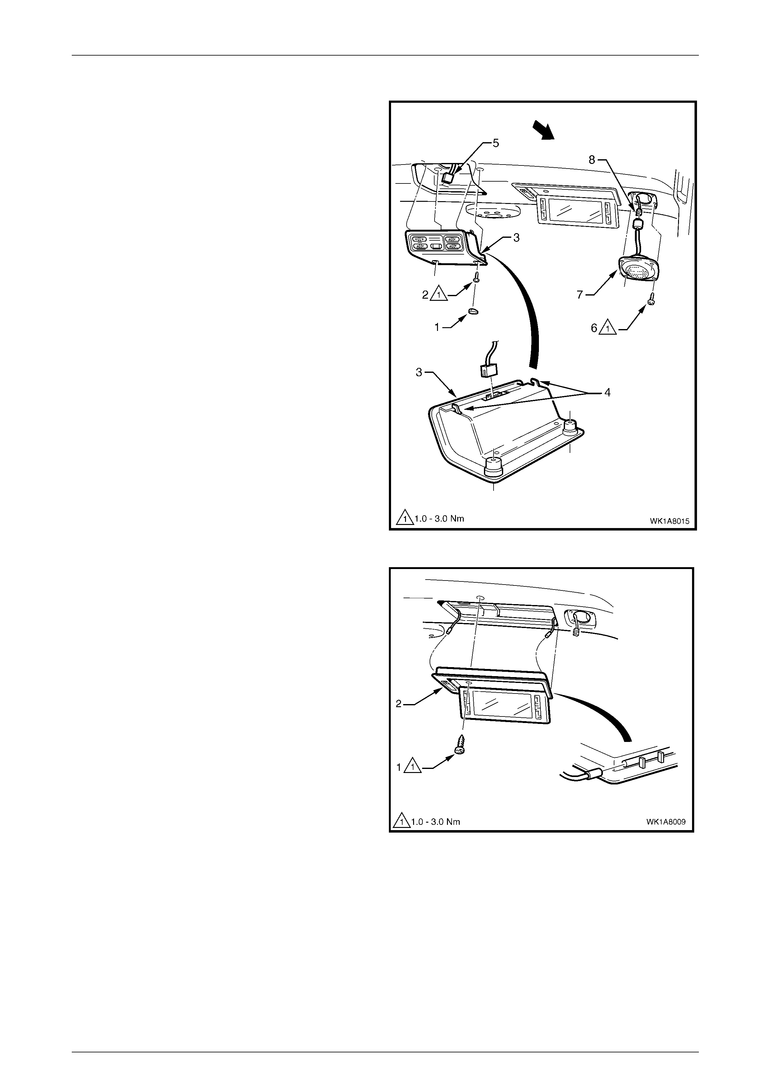
1 If fitted, remove blanking plug (1) and screw (2) , two
places, securing the remote control assembly (3) to
headlining support.
2 Disengage remote control locating lugs (4) and lower
control disconnect wiring harness connector (5) and
remove the control.
3 Remove the screw (6), four places, securing the
speaker (7) to centre support using an allen key and
disconnect wiring harness connector (8).
Figure 1A8 – 10
4 If fitted, remove the screw (1) securing illuminated
vanity mirror (2).
5 Lower the mirror, disconnect wiring harness connector
and remove mirror.
NOTE
The illuminated vanity mirrors can be assisted
from their position in the headlining by exerting
pressure on the rear of the mirror assembly via
the roof speaker cavity.
Figure 1A8 – 11
Headlining and Int eri or Tri m Page 1A8–14
23–OCT–2002 Page 1A8–14
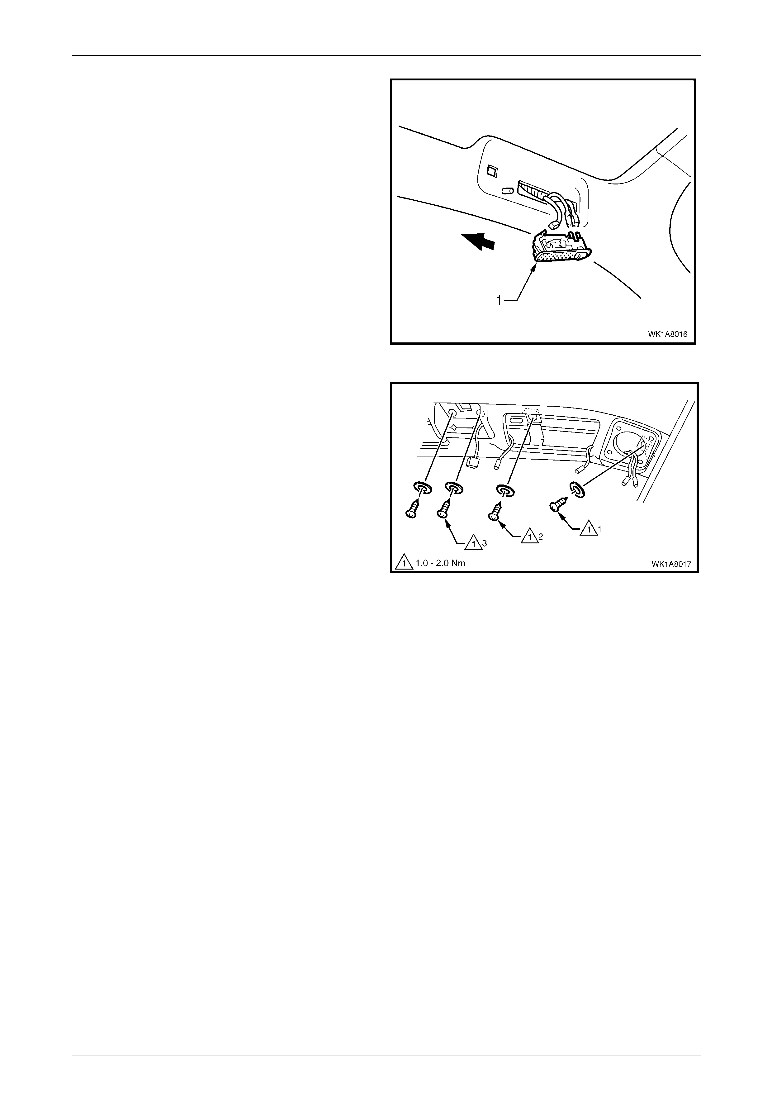
6 If fitted, prise reading lamp (1) from its location.
7 Disconnect the wiring harness connector and remove
the reading lamp.
Figure 1A8 – 12
8 From within the radio speaker cavity, if fitted, remove
the screw (1), one place each side, securing the
headlining centre support to the vehicle.
9 From within the vanity mirror cavity, if fitted, remove
the screw (2), one place each side.
10 From within the remote control cavity, if fitted, remove
the screw (3), two places.
Figure 1A8 – 13
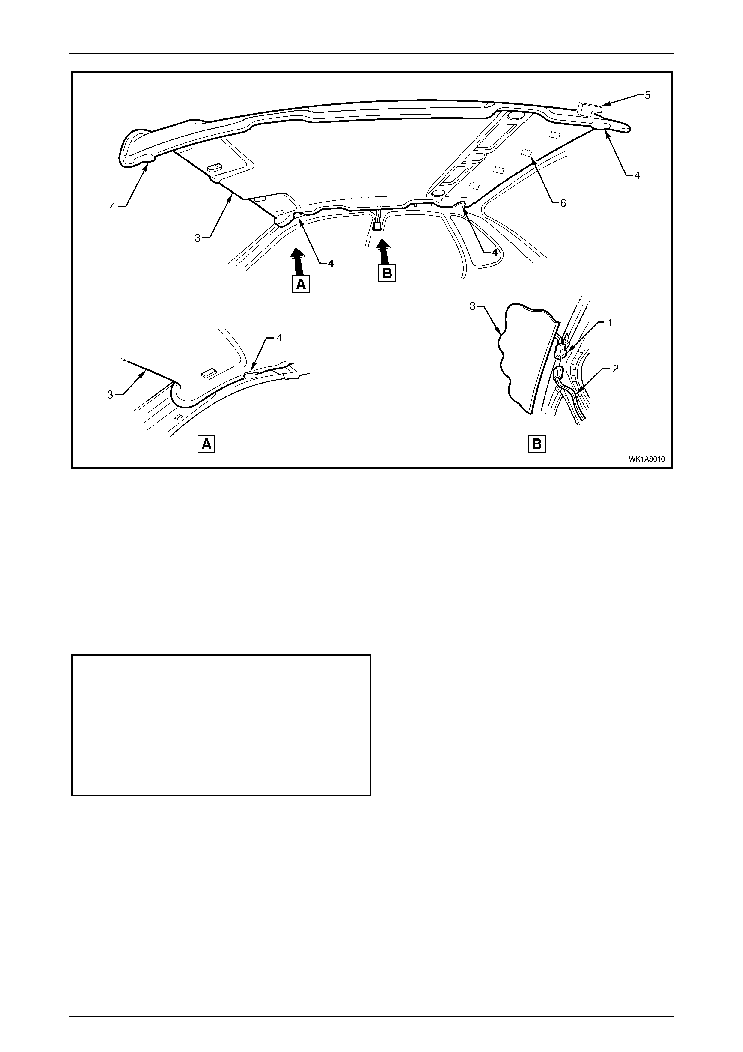
11 Disconnect the headlining assembly wiring harness (1) from the body wiring harness connector (2), located above
and slightly forward of the right-hand centre pillar, refer to Figure 1A8 – 14.
NOTE
It may be necessary to flex the headlining
assembly (3) down slightly to gain access to the
wiring harness connector.
12 With the aid of an assistant, flex the headlining assembly to disengage the corners from the two ‘D’ tabs (4) on
each side of the headlining and remove the foam tab (5) from the slot in the roof panel on each side of the
headlining, at the rear of the vehicle.
13 Unfasten the hook and loop strips on the headlining from the velcro on the roof (6).
14 Ease the headlining assembly from its position in the roof and turn the assembly so that it can be passed through
the passenger side front door, removing the assembly from the vehicle.
Headlining and Int eri or Tri m Page 1A8–15
23–OCT–2002 Page 1A8–15
Figure 1A8 – 14
Reinstall
Reinstallation of the headlining assembly is the reverse of the removal, noting the following:
1 Temporarily support the headlining assembly on the ‘D’ tabs before the trim components are reinstalled.
2 Push up on the headlining under the locations of the hook and loop to complete the reinstallation.
3 Reinstall the trim components.
4 Tighten the screws to the correct torque specification.
Remote control assembly attaching
screw torque specification.........................1.0 – 3.0 N.m
Speaker assembly attaching screw
torque specification...................................1.0 – 3.0 N.m
Vanity mirror attaching screw torque
specification ..............................................1.0 – 3.0 N.m
Headlining centre support attaching
screw torque specification.........................1.0 – 2.0 N.m
Headlining and Int eri or Tri m Page 1A8–16
23–OCT–2002 Page 1A8–16
2.7 Quarter Inner Rear Side Carpet
LT Section No. – 14-480
1 Remove the convenience net, refer to Section 1A8, 2.19 Convenience Net in the MY 2003 VY and V2 Series
Service Information.
2 Remove the rear compartment floor carpet assembly, refer to Section 1A8, 2.16 Rear Compartment Floor
Assembly in the MY 2003 VY and V2 Series Service Information.
3 Remove the rear end trim panel, refer to Section 1A8, 2.15 Rear End Trim Panel in the MY 2003 VY and V2 Series
Service Information.
Remove
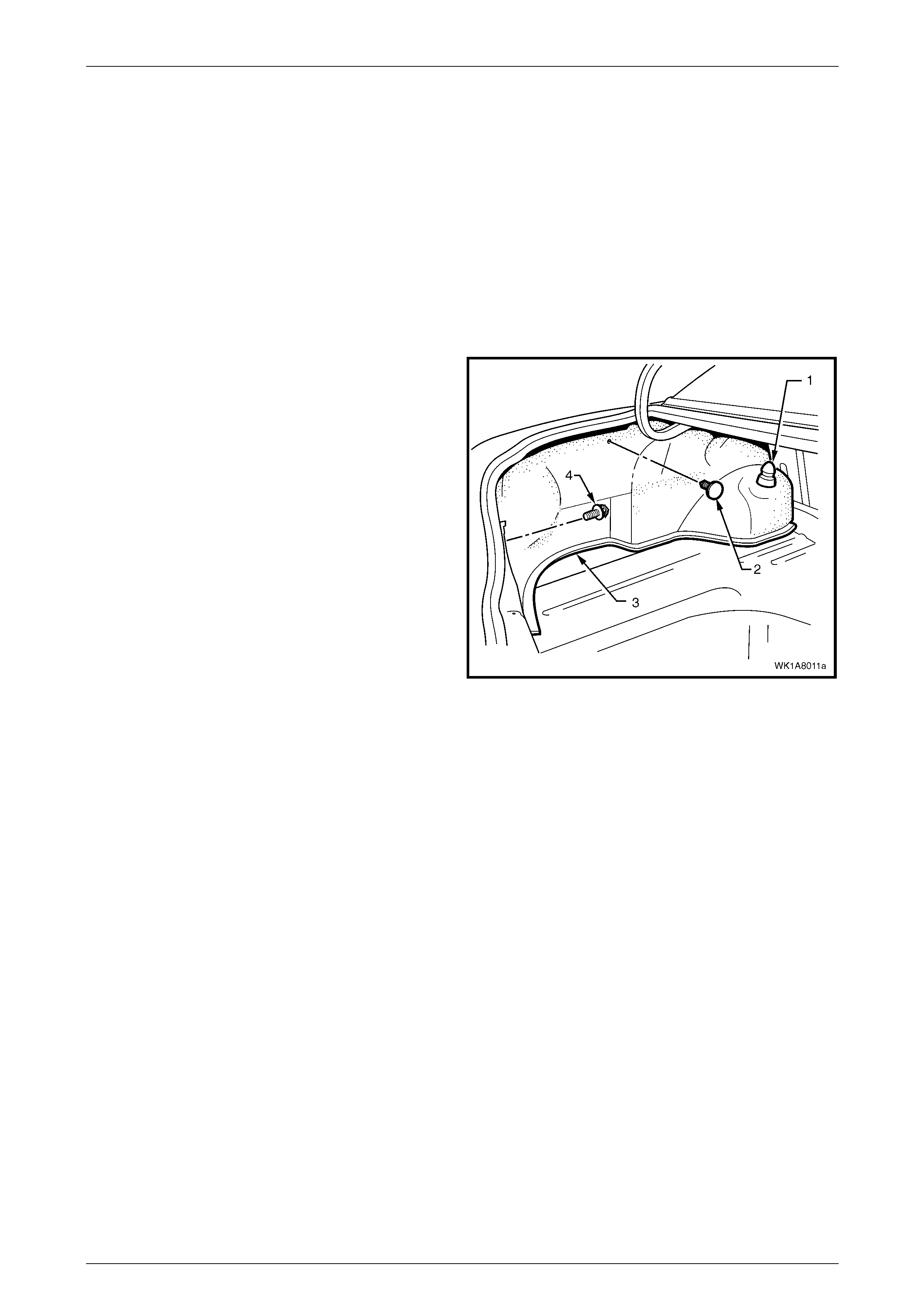
1 For the left hand side carpet, carefully prise off the
rear shock absorber access hole cover (1).
2 Carefully remove the retainer (2) from the quarter
inner rear side carpet (3).
3 Unhook the carpet flap from the rear compartment lid
hinge bracket.
4 Unscrew and remove the convenience net hook (4).
5 If required, remove the Jack.
6 Carefully remove the quarter inner rear side carpet.
Figure 1A8 – 15
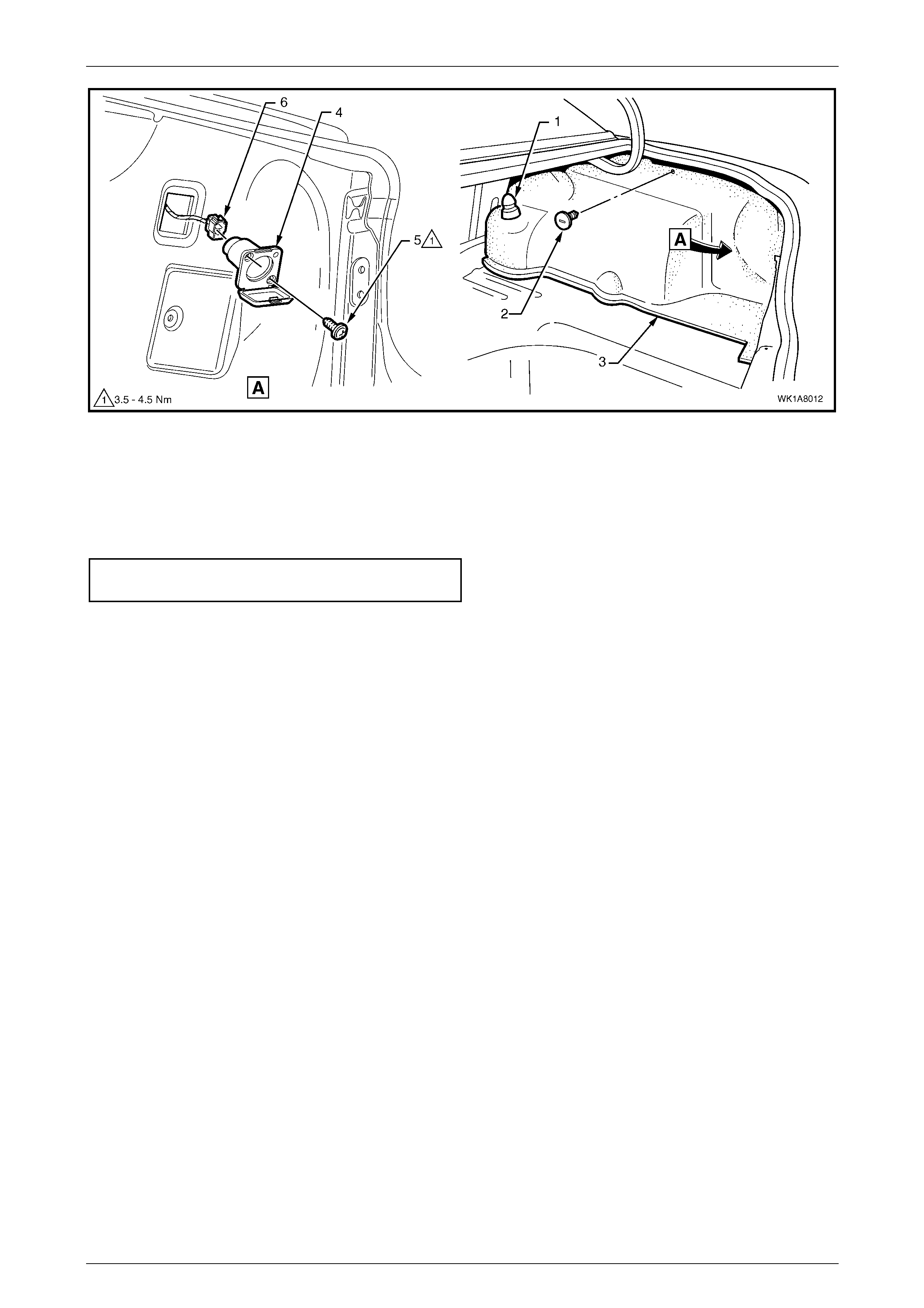
7 For the right hand side carpet, carefully prise off the rear shock absorber access hole cover (1), refer to Figure
1A8 – 16.
8 Carefully remove the retainer (2) from the quarter inner rear side carpet (3).
9 For vehicles fitted with the access door (4) remove the retainer (5).
10 Remove the power socket (6), where fitted. Open the power socket cover and unscrew the screw (7), two places.
11 Disconnect the wiring connector (8) and push the wires back through the carpet.
12 Unhook the carpet flap from the rear compartment lid hinge bracket.
13 Remove the convenience hook.
14 Carefully remove the quarter inner rear side carpet.
Headlining and Int eri or Tri m Page 1A8–17
23–OCT–2002 Page 1A8–17
Figure 1A8 – 16
Reinstall
1 The installation procedure for the quarter inner rear side carpet is the reverse of the removal procedure.
2 If fitted, tighten the screws to the correct torque specification.
Power socket assembly attaching
screw torque specification.........................3.5 – 4.5 N.m
Headlining and Int eri or Tri m Page 1A8–18
23–OCT–2002 Page 1A8–18
2.8 Spare Wheel Well Container
Remove
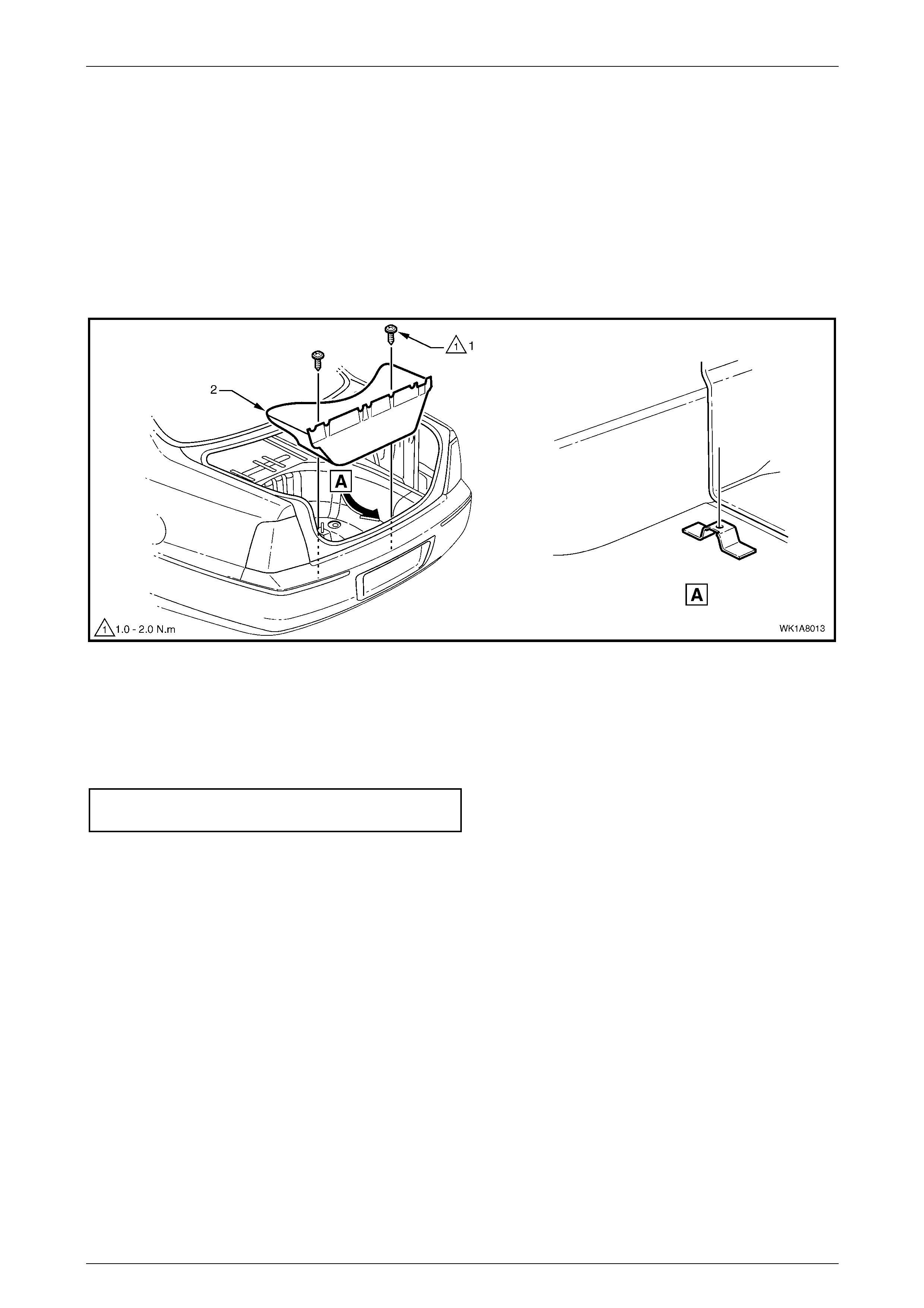
1 Open the rear compartment lid.
2 Remove the spare wheel, refer to Section 10, 2.3 Wheel Removal And Installation.
3 Unscrew the two screws (1) attaching the spare wheel well container (2) to the spare wheel well, refer to Figure
1A8 – 17.
4 Remove the spare wheel well container.
Figure 1A8 – 17
Reinstall
1 The installation procedure for the spare wheel well container is the reverse of the removal procedure.
2 Tighten screws to the correct torque specification.
Spare wheel well container screw
attaching torque ........................................ 1.0 – 2.0 N.m
Headlining and Int eri or Tri m Page 1A8–19
23–OCT–2002 Page 1A8–19
3 Specifications
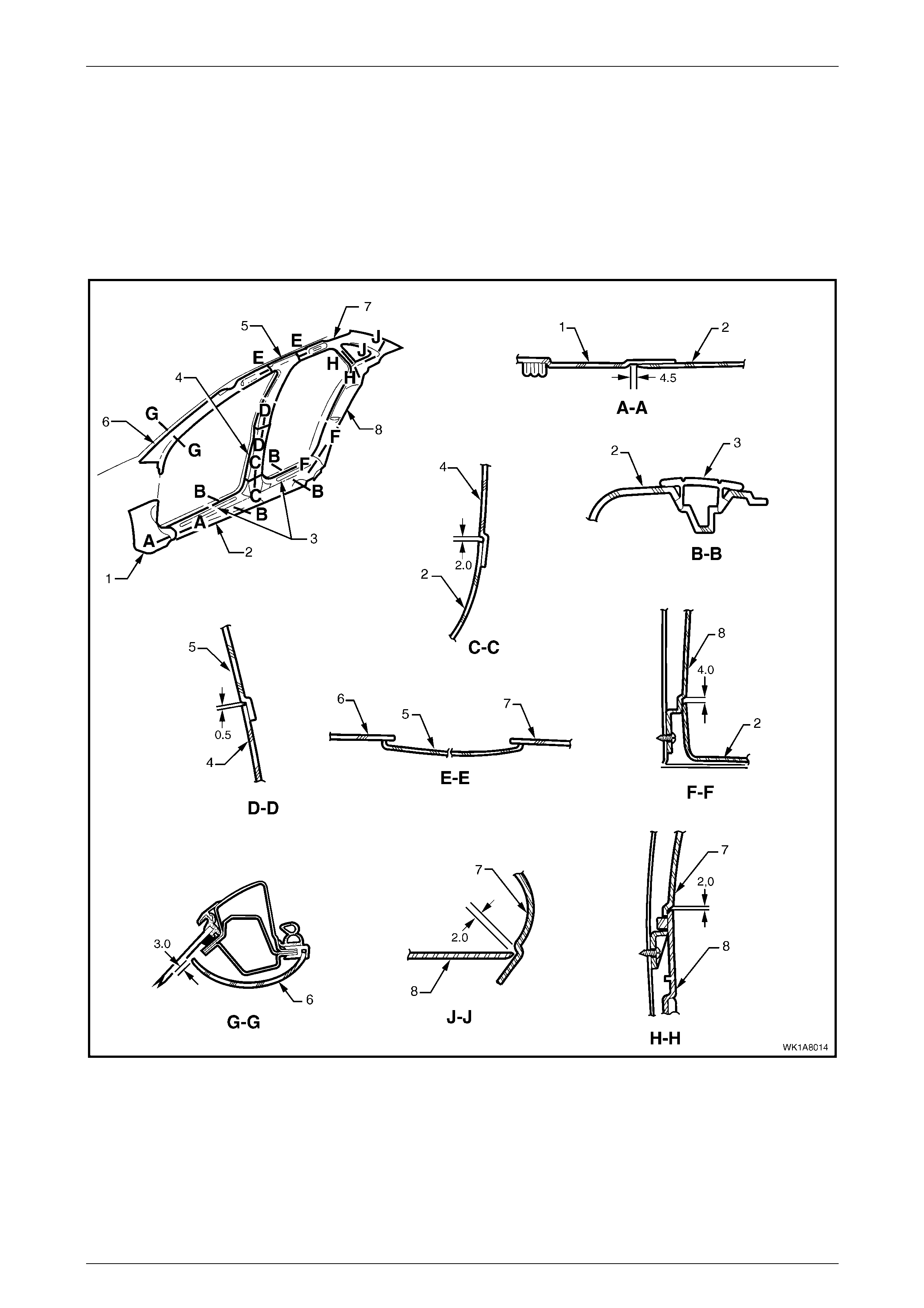
3.1 Trim Clearances
NOTE
All measurements are in millimetres.
Figure 1A8 – 18
Legend
1 Hinge Pillar Trim A s sembly
2 Side Sill Trim
3 Side Sill Trim Plate
4 Centre Pillar Lower Trim
5 Centre Pillar Upper Trim Assembly
6 Windshield Side Garnish
7 Body Lock Pillar Garnish
8 Body Lock Pillar Lower Trim

Headlining and Int eri or Tri m Page 1A8–20
23–OCT–2002 Page 1A8–20
4 Torque Wrench Specifications
Seat adjuster outer front cover attaching screw torque
specification..................................................................................1.0 – 3.0 N.m
Side sill trim attaching screw torque specification........................ 1.0 – 3.0 N.m
Body lock pillar lower trim attaching screw torque specification... 1.0 – 3.0 N.m
Body lock pillar garnish attaching screw torque specification.......1.0 – 3.0 N.m
Child harness fitting attaching screw torque specification........ 15.0 – 25.0 N.m
Remote control assembly attaching screw torque specification...1.0 – 3.0 N.m
Speaker assembly attaching screw torque specification..............1.0 – 3.0 N.m
Vanity mirror attaching screw torque specification .......................1.0 – 3.0 N.m
Headlining centre support attaching screw torque specification...1.0 – 2.0 N.m
Power socket assembly attaching screw torque specification...... 3.5 – 4.5 N.m
Spare wheel well container screw attaching torque......................1.0 – 2.0 N.m