
Bumper Ba r s Page 1D–1
Page 1D–1
Section 1D
Bumper Bars
ATTENTION
Before performing any Service Operation or other procedure described in this Section, refer to Section 00
Warnings, Cautions and Notes for correct workshop practices with regard to safety and/or property damage.
1 General Information............................................................................................................................... 2
2 Service Operations................................................................................................................................3
2.1 Paint Masking.........................................................................................................................................................3
Front Bumper..........................................................................................................................................................3
Rear Bumper...........................................................................................................................................................4
2.2 Front Bumper Fascia Assembly............................................................................................................................5
Remove ...................................................................................................................................................................5
Disassemble ...........................................................................................................................................................6
Front Bumper Fascia Moulding...........................................................................................................................6
Front Fog and Cornering Lamp Cover, Level 1 ..................................................................................................6
Front Fog and Cornering Lamp Assembly, Except Level 1.................................................................................7
Lower Radiator Grille..........................................................................................................................................9
Reinstall ................................................................................................................................................................10
2.3 Front Fascia Support...........................................................................................................................................11
Remove .................................................................................................................................................................11
Reinstall ................................................................................................................................................................11
2.4 Rear Bumper Fascia Assembly...........................................................................................................................12
Remove .................................................................................................................................................................12
Disassemble .........................................................................................................................................................14
Rear Bumper Fascia Moulding.........................................................................................................................14
License Plate Lamp Assembly..........................................................................................................................14
License Plate Lamp Harness, Vehicles Without Reverse Park Aid ..................................................................15
License Plate Lamp Harness, Vehicles With Reverse Park Aid .......................................................................15
License Plate Lamp Carrier, Except Level 4 RHD............................................................................................16
License Plate Surround, Level 4 RHD..............................................................................................................17
Towbar Opening Cover.....................................................................................................................................17
Rear Bumper Fascia Anchor Plate Assembly...................................................................................................18
Rear Bumper Fascia Mounting Bracket Assembly............................................................................................18
Reinstall ................................................................................................................................................................19
2.5 Rear Bumper Fascia Guide Assembly................................................................................................................20
Remove .................................................................................................................................................................20
Reinstall ................................................................................................................................................................20
2.6 Rear Bumper Fascia Centre Support..................................................................................................................21
Remove .................................................................................................................................................................21
Reinstall ................................................................................................................................................................21
3 Torque Wrench Specifications........................................................................................................... 22

Bumper Ba r s Page 1D–2
Page 1D–2
1 General Information
With the following exceptions, MY 2004 WK Series Bumper Bars information carries over from MY 2003 VY Series
vehicles. For information not contained within this Section, refer to Section 1D Bumper Bars in the MY 2003 VY and V2
Series Service Information.
• Front Bumper Fascia Assembly
• Front Fascia Support
• Rear Bumper Fascia Assembly
• Rear Bumper Fascia Guide Assembly
• Rear Bumper Fascia Centre Support
The bumper fascia assemblies fitted to MY2004 WK series vehicles are constructed from polypropylene resin. Two styles
of front bumper fascia are available, depending on the Model Level. Model Levels 1, 2, 4 & 5 utilise one style, whilst
Level 3, SS Caprice adopts the second, sportier looking fascia.
Fog lamps are installed on all Levels with the exception of Level 1, which incorporate fog lamp covers in place of the fog
lamps.
Two attachment lugs and two support lugs for the fog lamps are moulded as part of the front bumper fascia. This running
change is introduced to improve the rigidity of the interface with the fog lamps.
NOTE
For Model Level designations, refer to Section 0A
General Information.
Five rear bumper fascias are available, depending on Model Level.
• Model Level 1, 2 & 5 Vehicles with Reverse Park Aid.
Vehicles without Reverse Park Aid.
• Model Level 3, SS Caprice Vehicles with Reverse Park Aid.
Vehicles without Reverse Park Aid.
• Model Level 4 Vehicles with Reverse Park Aid and license plate surround
Two fascia supports are installed behind the front bumper fascia. These supports are attached to the steel front bumper
impact bar assembly. The bar assembly is attached directly to the front side rails and is designed to assist in the
dispersion of crash energy and plays an integral role with the vehicle’s safety systems.
A steel rear bumper impact bar is also installed behind the rear bumper fascia on all models.
The rear fascia assemblies may include four rear sensor assemblies and wiring harness for Reverse Parking Aid (RPA).
NOTE
If the vehicle is fitted with RPA, a new rear
bumper fascia service part will require
modification prior to painting and installation. For
further information on RPA, refer to Section 12 F
Reverse Park Aid and Section 1D Bumper Bars
in the MY 2003 VY and V2 Series Service
Information.
Bumper Ba r s Page 1D–3
Page 1D–3
2 Service Operations
2.1 Paint Masking
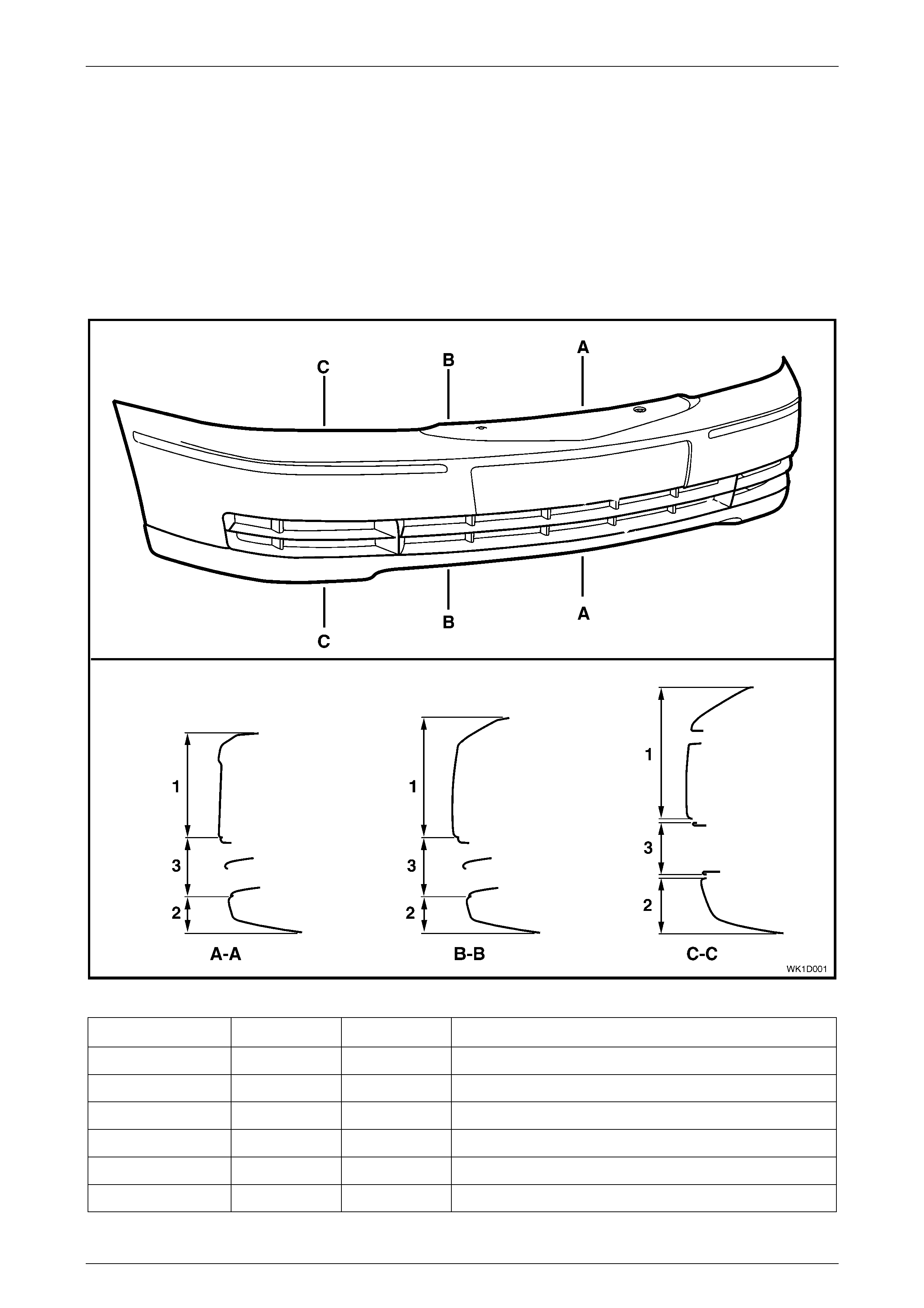
The following illustrations show the front and rear bumper fascia paint masking areas for each vehicle model and are
provided to assist when painting a bumper fascia to match the factory finish.
For further information on the specific Model Levels, refer to Section 0A General Information.
Front Bumper
Figure 1D – 1
Model Area 1 Area 2 Area 3
Level 1 – Gulf States Body Colour Skirt Black Fog Lamp Cover and Lower grille – finish of supplied part
Level 2 – Gulf States Body Colour Body Colour Fog lamp and Lower grille – finish of supplied part
Level 3 – Gulf States Body Colour Body Colour Fog lamp and Lower grille – finish of supplied part
Level 4 – Domestic Body Colour Accent Fog lam p and Lower grille – finish of supplied part
Level 5 – Gulf States Body Colour Accent Fog lamp and Lower grille – finish of supplied part
Level 5 – Domestic Body Colour Body Colour Fog lamp and Lower grille – finish of supplied part
Bumper Ba r s Page 1D–4
Page 1D–4
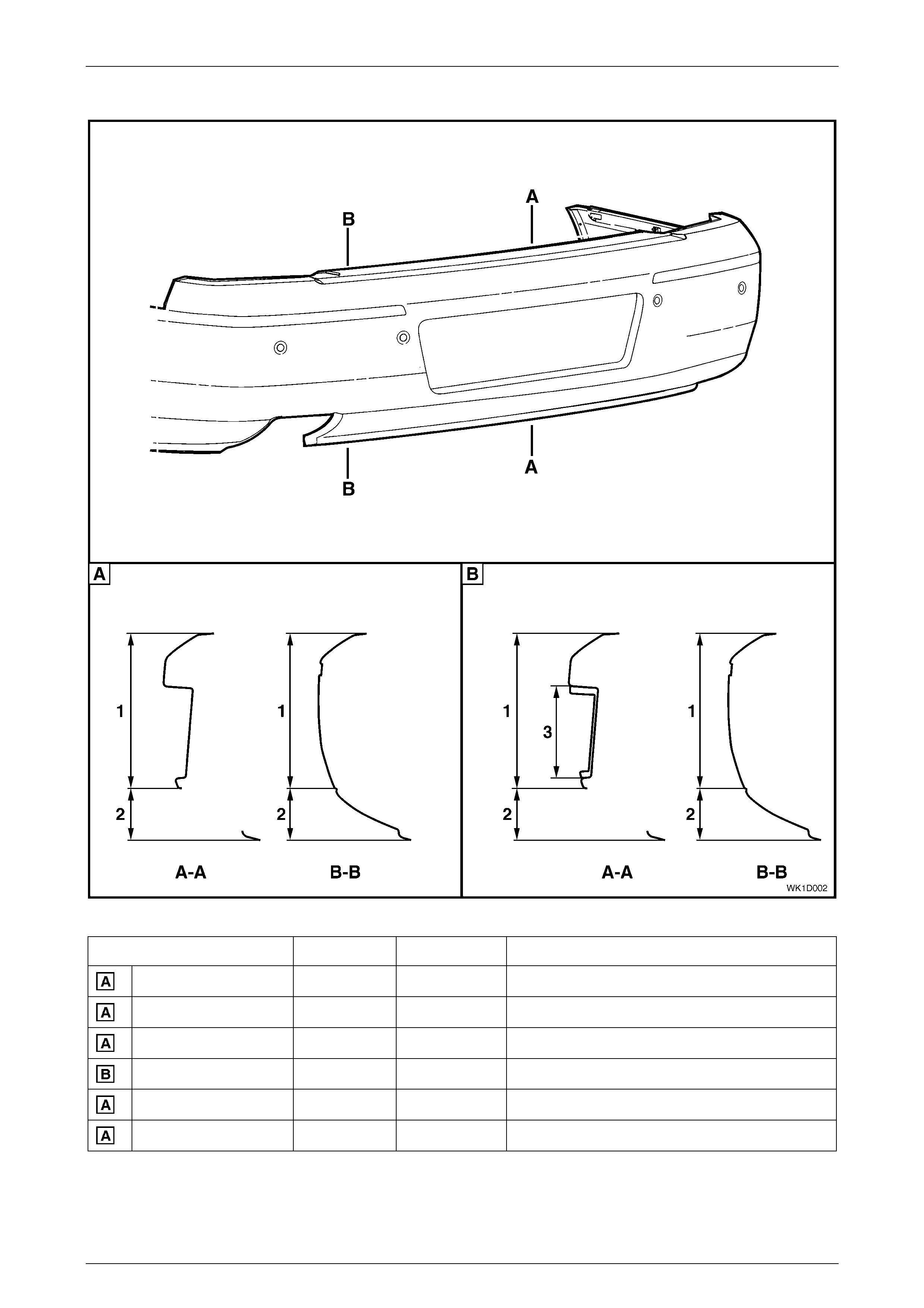
Rear Bumper
Figure 1D – 2
Model Area 1 Area 2 Area 3
Level 1 – Gulf States Body Colour Skirt Black No license plate surround fit t ed
Level 2 – Gulf States Body Colour Body Colour No lic ense pl ate surround fitted
Level 3 – Gulf States Body Colour Body Colour No lic ense pl ate surround fitted
Level 4 – Domestic B ody Col our Acc ent Licens e Plate Surround – fi nish of suppli ed part
Level 5 – Gulf States Body Colour Accent No li cense plate surround fitted
Level 5 – Domestic B ody Col our Body Colour No l i cense plate surround fitted
Bumper Ba r s Page 1D–5
Page 1D–5
2.2 Front Bumper Fascia Assembly
LT Section – 07-500
Remove
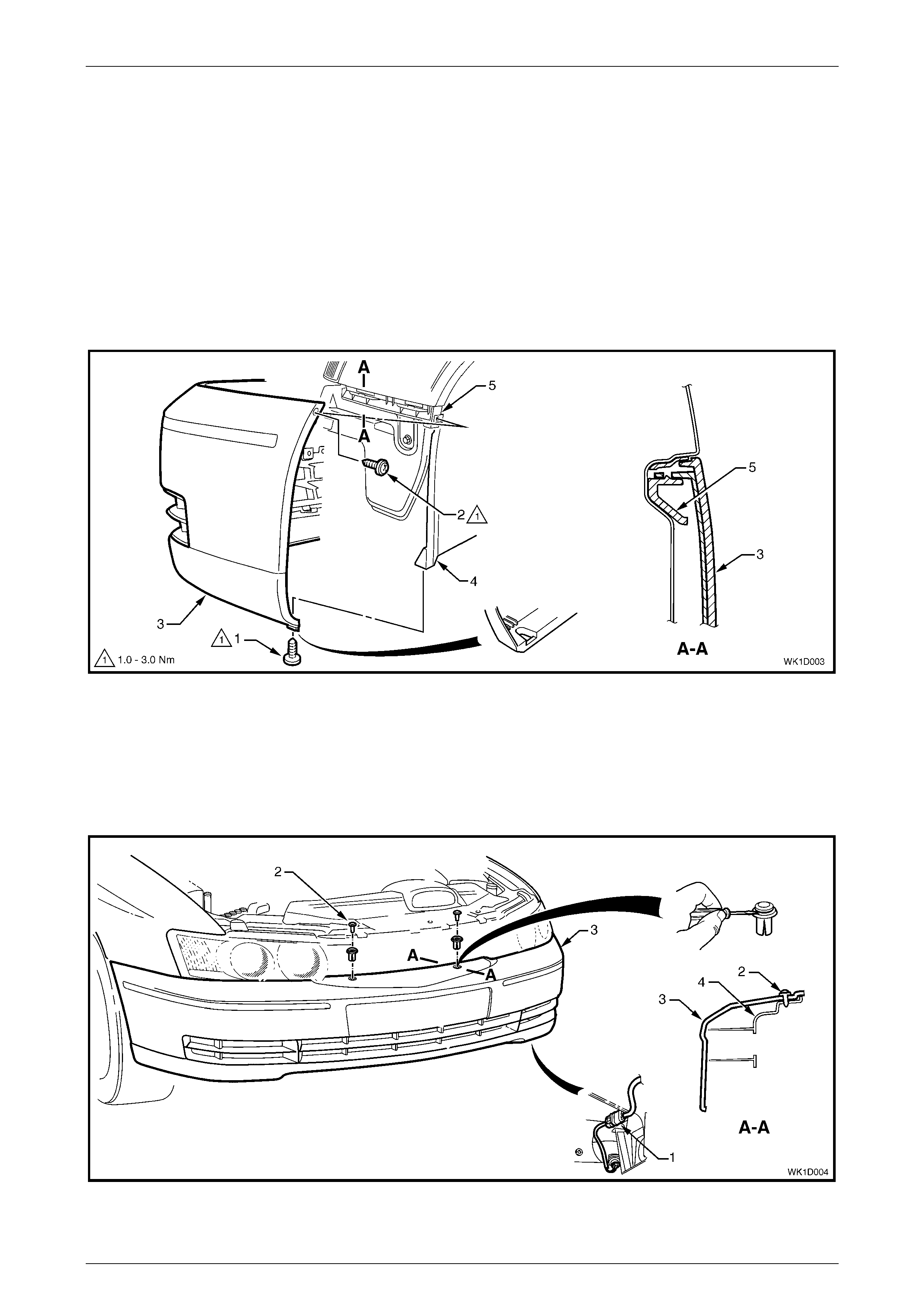
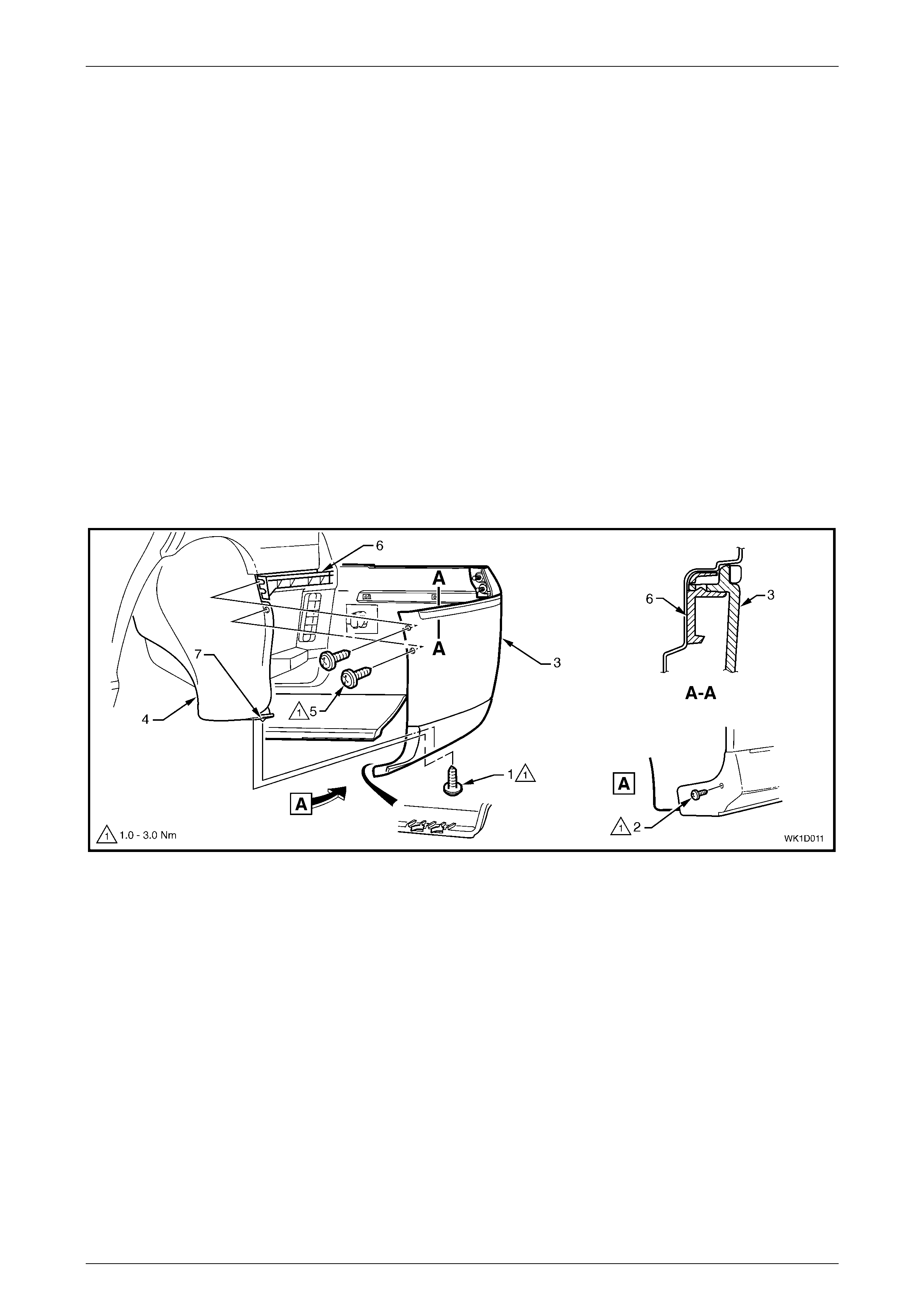
1 From each side of the vehicle:
a Remove the two screws (1 and 2) attaching the front bumper fascia assembly (3) to the front wheelhouse
liner (4) and front bumper fascia guide assembly (5), refer to Figure 1D – 3.
b Carefully unclip the fascia assembly from the guide assembly by grasping the upper end of the fascia and
pulling away from the vehicle.
Figure 1D – 3
2 If fitted, disconnect the front fog lamp wiring connector (1), one place each side of the vehicle, refer to
Figure 1D – 4.
3 Prise the centre pin and remove the retainers (2), in two places, attaching the fascia assembly (3) to the front fascia
support (4).
4 With the aid of an assistant remove the fascia assembly and store in a safe place.
Figure 1D – 4
Bumper Ba r s Page 1D–6
Page 1D–6
Disassemble
Front Bumper Fascia Moulding
Remove
If the moulding (3) is to be reused, take care
as the speed nuts can cut into and break the
lugs during removal, refer to Figure 1D – 5.
1 From the rear of the front bumper fascia (1), remove the retaining speed nut (2), in six places, securing the
moulding to the bumper fas cia .
2 Withdraw the moulding from the recess in the front of the bumper fascia.
Figure 1D – 5
Reins tal l
1 Fit the moulding into the bumper fascia, locating the lugs in their respective holes, refer to Figure 1D – 5.
2 Fit a speed nut to the rear of each lug securely.
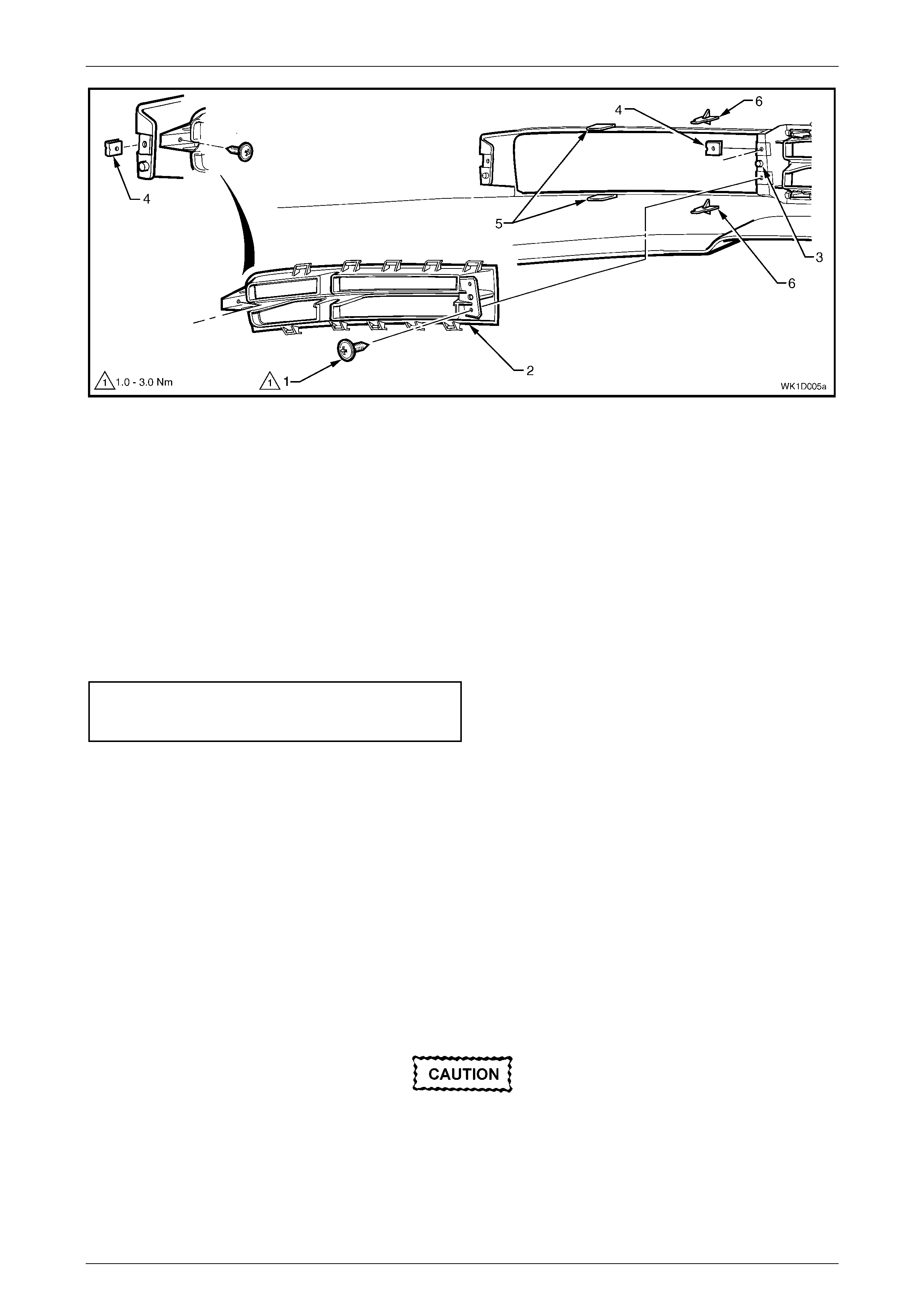
Front Fog and Cornering Lamp Cover, Level 1
Remove
1 From the rear of the fascia, remove the retaining screw (1), in three places, securing the cover (2) to the bumper
fascia. Refer to Figure 1D – 6.
2 Rotate the inner end of the cover away from the bumper fascia and unhook the outer side of the cover from the
bumper fascia.
3 Remove t he cover .
Bumper Ba r s Page 1D–7
Page 1D–7
Figure 1D – 6
Legend
1 Retaining Screw
2 Lamp Cover 3 Guide Post
4 J-nut 5 Support Lug (when present )
6 A ttachment Lug (when present)
Reinstall
1 Check that the J-nut (4), in three places, is correctly positioned, refer to Figure 1D – 6.
2 Install the inner side of the cover towards the fascia, ensuring the cover locates onto the guide post (3).
3 Rotate the outer side of the cover into the fascia.
4 Install and tighten the retaining screws, in three places, to their specified torque.
Front fog and cornering lamp
cover attaching screw
torque specific atio n ....................................1.0 – 3.0 Nm
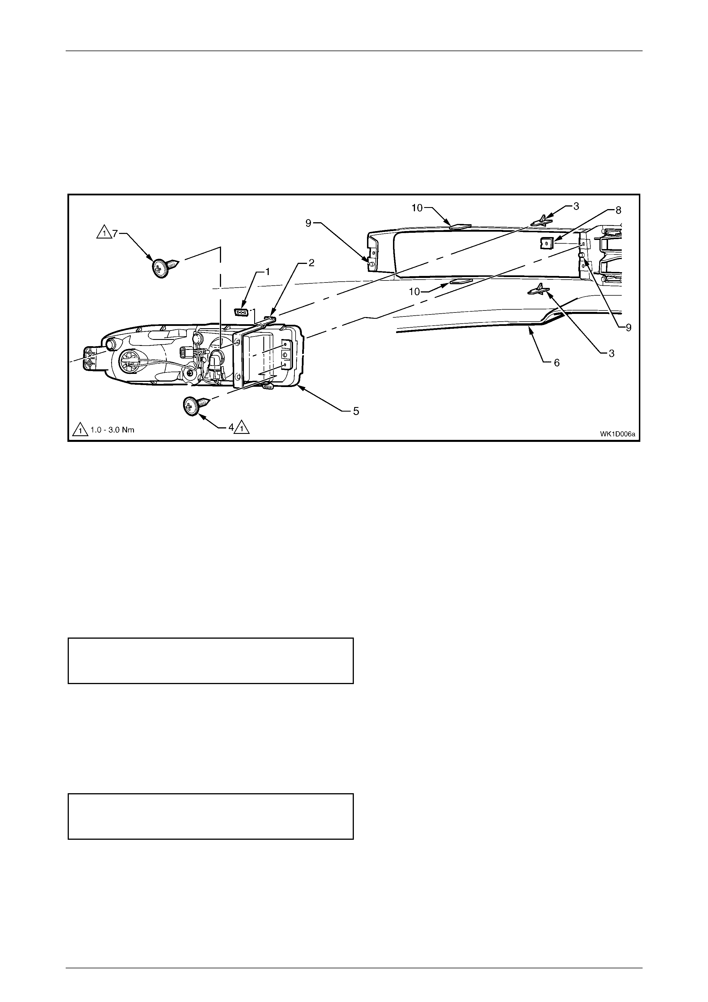
Front Fog and Cornering Lamp Assembly, Except Level 1
The following procedure is applicable to the front bumper fascia including two attachment lugs and two support lugs for
the front fog and cornering lamp assemblies fitted with a metal strip bracket. For the procedure of the lamp assemblies
installed without the metal strip bracket, refer to Section 12B, 2.7 Fog and Cornering Lamp Assembly.
NOTE
The two attachment lugs and two support lugs
may not be present on the front bumper fascia as
the rigidity improvement of the interface with the
front fog and cornering lamp assemblies is a
running change.
Remove
If the fascia is to be reused, take care when
removing the razor blade clips to prevent
damage to the lugs (3).
1 From the rear of the fascia, remove the razor blade retaining clip (1), in two places, securing the metal strip
bracket (2) to the attachment lugs (3), refer to Figure 1D – 7.
2 Remove the screw (4), in three places, attaching the lamp assembly (5) to the bumper fascia (6).
Bumper Ba r s Page 1D–8
Page 1D–8
3 Withdraw the lamp and bracket assembly from the rear of the bumper fascia.
4 If required, remove the two screws (7) and then the metal strip bracket from the lamp assembly.
NOTE
For further service of the front fog and cornering
lamp assembly refer to Section 12B Lighting
System.
Figure 1D – 7
Legend
1 Razor B l ade Retaining Clip
2 Metal Strip Bracket
3 Attachment Lugs
4 A ttaching Screw (lamp housing)
5 Fog and Corneri ng Lam p Assem bly
6 Front Bumper Fascia
7 Attaching Screw (bracket)
8 J-nut
9 Guide Pins
10 Support Lugs
Reinstall
1 If required, install the metal strip bracket and tighten the two retaining screws (7) to their specified torque, refer to
Figure 1D – 7.
Front fog and cornering lamp
metal strip bracket attaching screws
torque specific atio n ....................................1.0 – 3.0 Nm
2 Check that the J-nut (8), in three places, is correctly positioned.
3 Locate the lamp housing onto the two guide pins (9), between the two support lugs (10) and locate the bracket on
the two attachment lugs (3).
4 Fit the razor blade retaining clip (1), in two places, to the rear of each attachment lug securely.
5 Install and tighten the three retaining screws (4) to their specified torque.
Front fog and cornering lamp
assembly attaching screws
torque specific atio n ....................................1.0 – 3.0 Nm
NOTE
Following installation of the bumper fascia
assembly, aim the fog lamps, refer to
Section 12B, 2.1 Front Fog Lamp Aiming.
Bumper Ba r s Page 1D–9
Page 1D–9
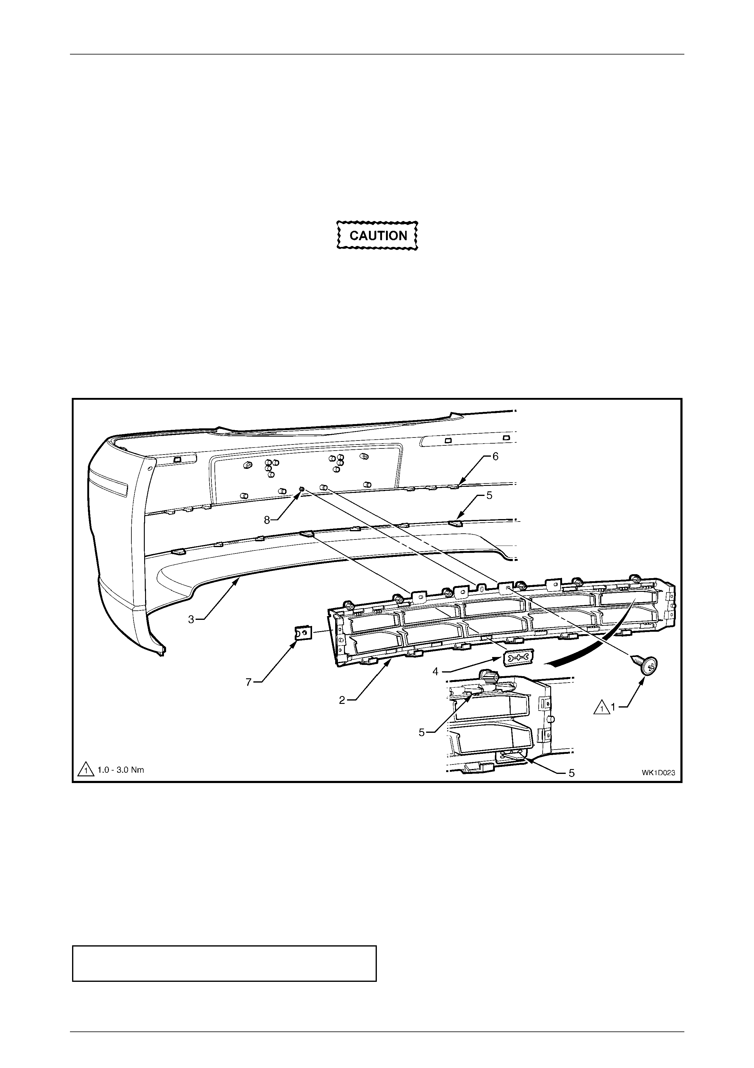
Lower Radiator Grille
Remove
1. Remove both front fog and cornering lamp assemblies or front fog and cornering lamp covers as previously
described.
2 Remove the screw (1), in four places, attaching the lower radiator grille (2) to the bumper fascia (3), refer to
Figure 1D – 8.
If the fascia is to be reused, care must be
taken when removing the razor blade
retaining clips (4) to prevent damage to the
lugs (5).
3 Remove the three razor blade retaining clips, in three places, securing the lower grille to the bumper fascia.
4 Unclip the retainers (6), in 10 places, securing the lower grille to the bumper fascia.
5 Remove the lower radiator grille.
Figure 1D – 8
Reinstall
1 Check that the J-nut (7), in four places, is correctly positioned on the lower radiator grille, refer to Figure 1D – 8.
2 Locate the lower radiator grille onto the guide post (8) and then clip into place, in 10 places.
3 Fit a razor blade retaining clip to the rear of each lug securely.
4 Install and tighten the four retaining screws (1) to their specified torque.
Lower radiator grille attaching screw
torque specific atio n ....................................1.0 – 3.0 Nm
5 Install the front fog and cornering lamp assemblies or front fog and cornering lamp covers as previously described.

Bumper Ba r s Page 1D–10
Page 1D–10
Reinstall
1 Refinish the bumper fascia assembly in accordance with procedures in 2.1 Paint System, Section 1D Bumper Bars
in the MY 2003 VY and V2 Series Service Information.
2 With the aid of an assistant, fit the front bumper fascia assembly onto the vehicle.
3 Insert the two scrivets (2) attaching the fascia assembly (3) to the fascia support (4), refer to Figure 1D – 4.
4 Align the side of the fascia assembly to the fender, clip the fascia assembly into the guide assembly and install the
screw (2), refer to Figure 1D – 3. Repeat for the opposite side.
5 Install the screw (1), each side, attaching the fascia assembly to the front wheelhouse liner.
6 Tighten the screws to the specified torque.
Front bumper fascia assembly to
front wheelhouse liner screw
torque specific atio n ....................................1.0 – 3.0 Nm
Front bumper fascia assembly to
front bumper fascia guide
assembly screw torque
specification.................................................1.0– 3.0 Nm
7 Reconnect the fog lamp wiring connectors if fitted, refer to (1), Figure 1D – 4.
Bumper Ba r s Page 1D–11
Page 1D–11
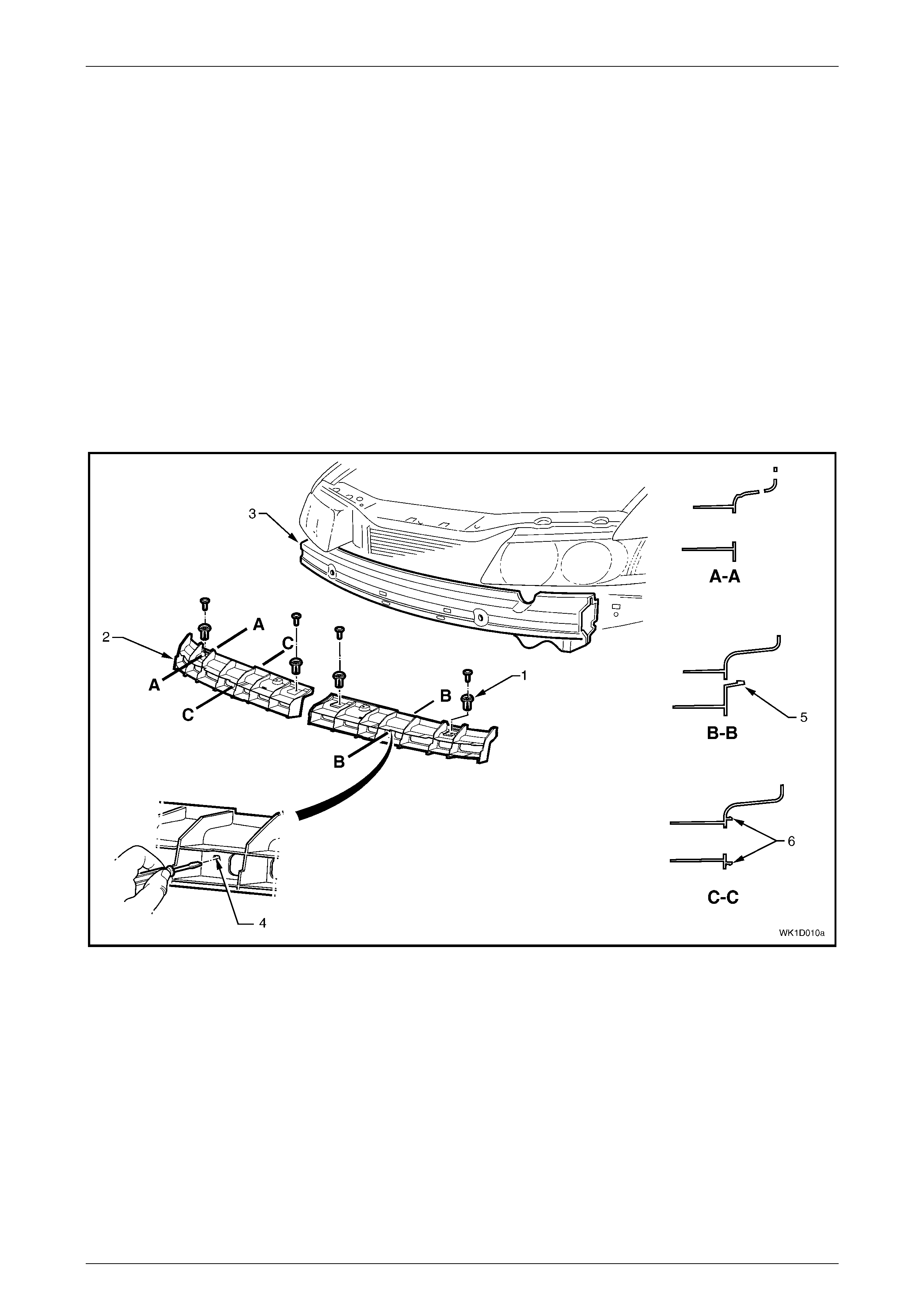
2.3 Front Fascia Support
Remove
The front fascia supports not only act as a mount and support for the bumper fascia, but are also critical in the dispersion
of crash energy. Hence, they play an integral role in the operation of the vehicle’s safety systems.
Repair of the fascia supports should be limited to replacement to ensure correct airbag and seatbelt pretensioner
operation.
Each Fascia support is removed separately, with the removal procedure for both fascia supports being identical.
1 Remove the front bumper fascia assembly, refer to 2.2 Front Bumper Fascia Assembly.
2 Prise the centre pin and remove the retainer (1), in two places, securing the front fascia support (2) to the front
bumper impact bar (3).
3 Insert a flat blade screwdriver into the opening (4) in the fascia support and depress the tab (5). Whilst depressing
the tab, slightly rotate the bottom of the fascia support upwards to release the remaining two retaining clips (6).
4 Remove the fascia support.
Figure 1D – 9
Reinstall
1 Align the three fascia support retaining clips (5 and 6) with the front bumper impact bar. Push the fascia support
into the front bumper to engage the retaining clips.
2 Install the fascia support retainers (1).
3 Reinstall the bumper fascia as required, refer to 2.2 Front Bumper Fascia Assembly.
Bumper Ba r s Page 1D–12
Page 1D–12
2.4 Rear Bumper Fascia Assembly
LT Section No. – 07-525
If required, first remove the following components:
1 Rear end trim panel, refer to Section 1A8, 4.12 Rear End Trim Panel in the MY 2003 VY and V2 Series Service
Information.
2 Quarter inner rear side carpet, refer to Section 1A8, 2.7 Quarter Inner Rear Side Carpet.
Remove
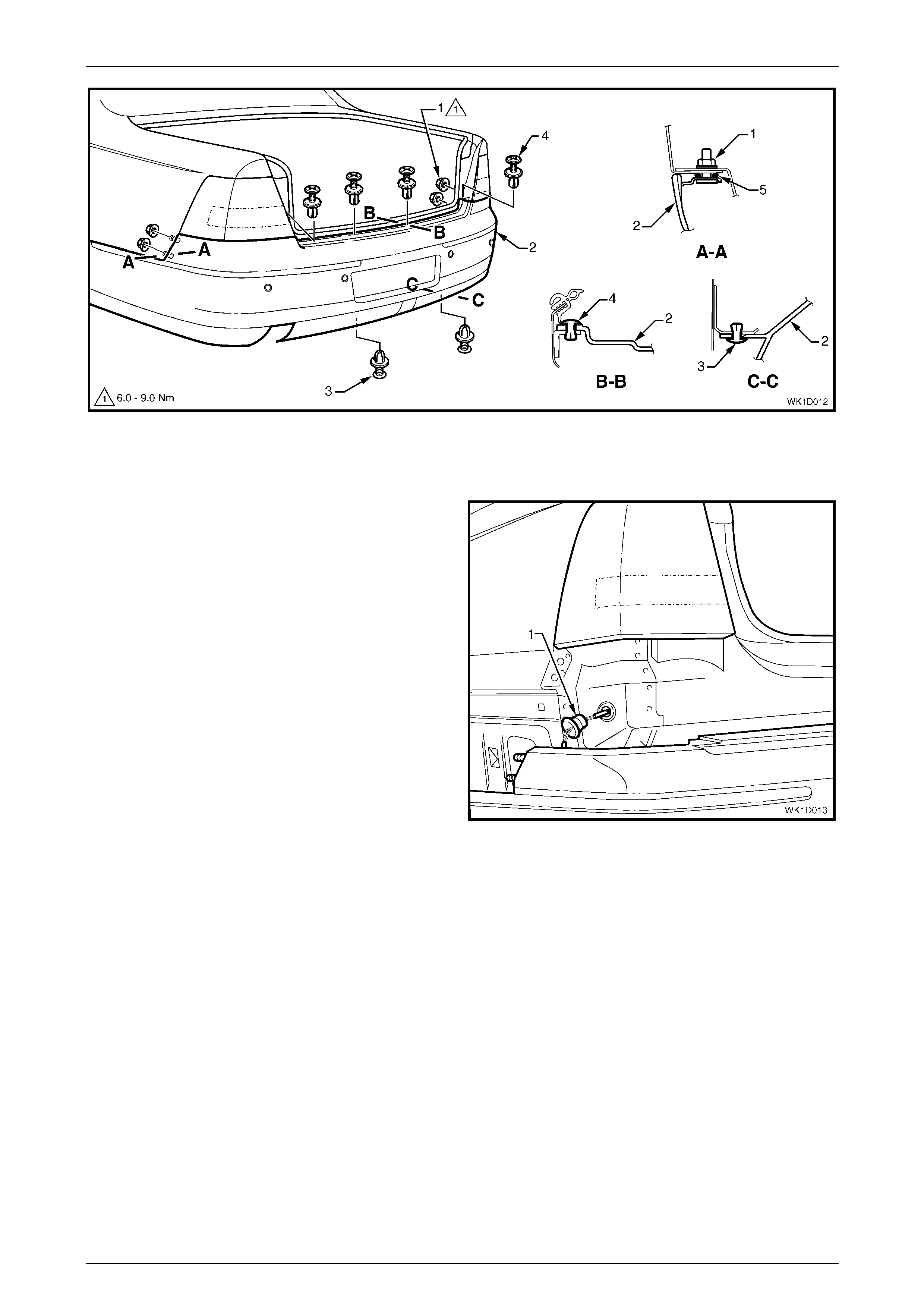
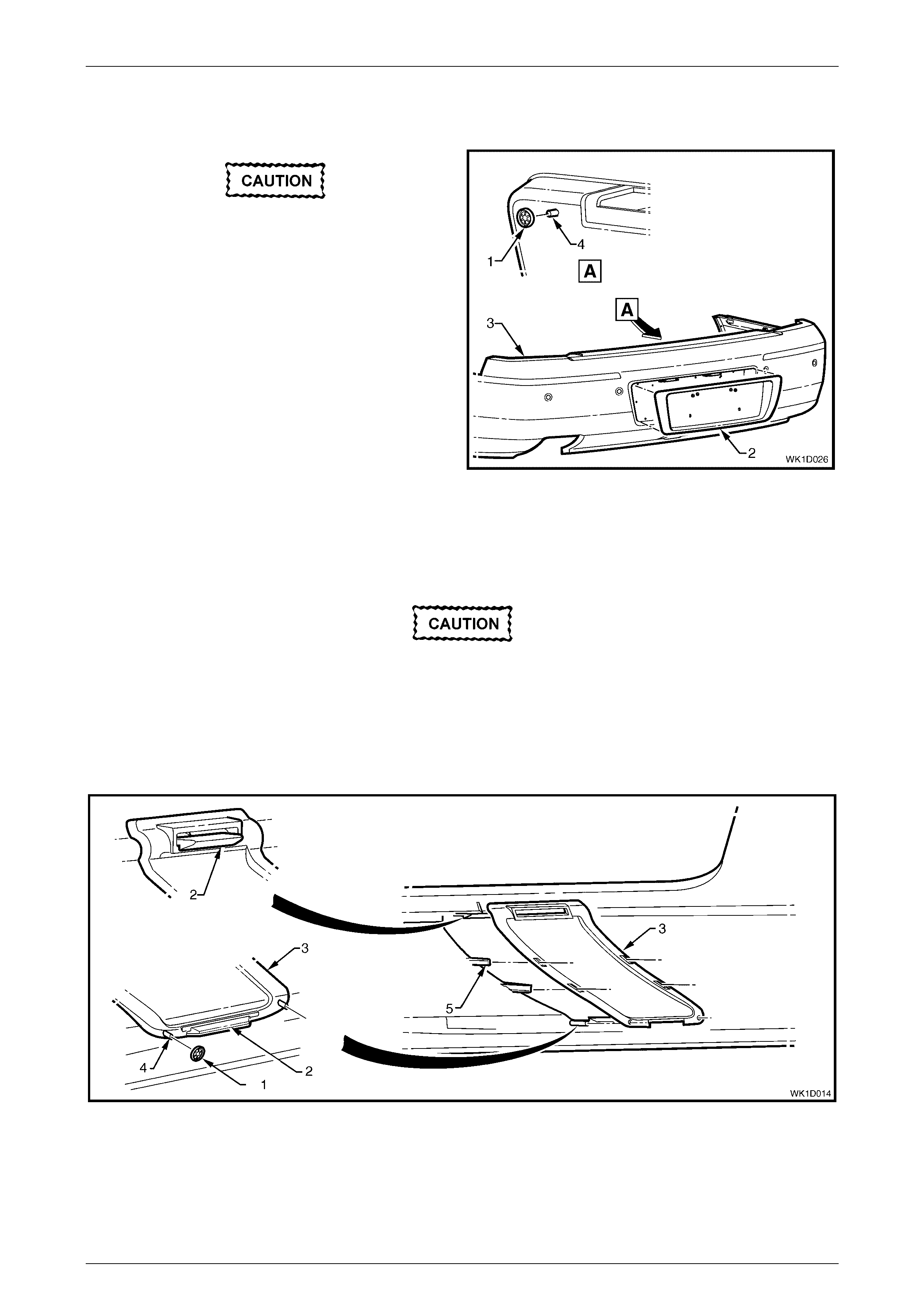
1 From each side of the vehicle:
a For Levels 1, 2, 4 & 5, remove the screw (1), one place each side, or for Level 3 vehicles, remove the
screw (2), in two places each side, attaching the rear bumper fascia assembly (3) to the rear wheelhouse
liner (4). Refer to Figure 1D – 10.
b Remove the screw (5), in two places, attaching the rear bumper fascia assembly to the liner and rear bumper
fascia guide assembly (6).
c Carefully unclip the fascia assembly from the guide assembly by grasping the upper end of the fascia and
pulling away from the vehicle, also disconnecting the liner lug (7) from the bumper fascia assembly, except
for Level 3 vehicles.
Figure 1D – 10
2 Remove the nuts (1), in two places each side, attaching the fascia assembly (2) to the vehicle, refer to
Figure 1D – 11.
3 Remove the two retainers (3) from below the fascia assembly.
4 Remove the centre section of the rear compartment lid weatherstrip to allow access to the four upper retainers (4).
5 Remove the four upper retainers attaching the fascia assembly to the rear bumper fascia centre support assembly.
Bumper Ba r s Page 1D–13
Page 1D–13
Figure 1D – 11
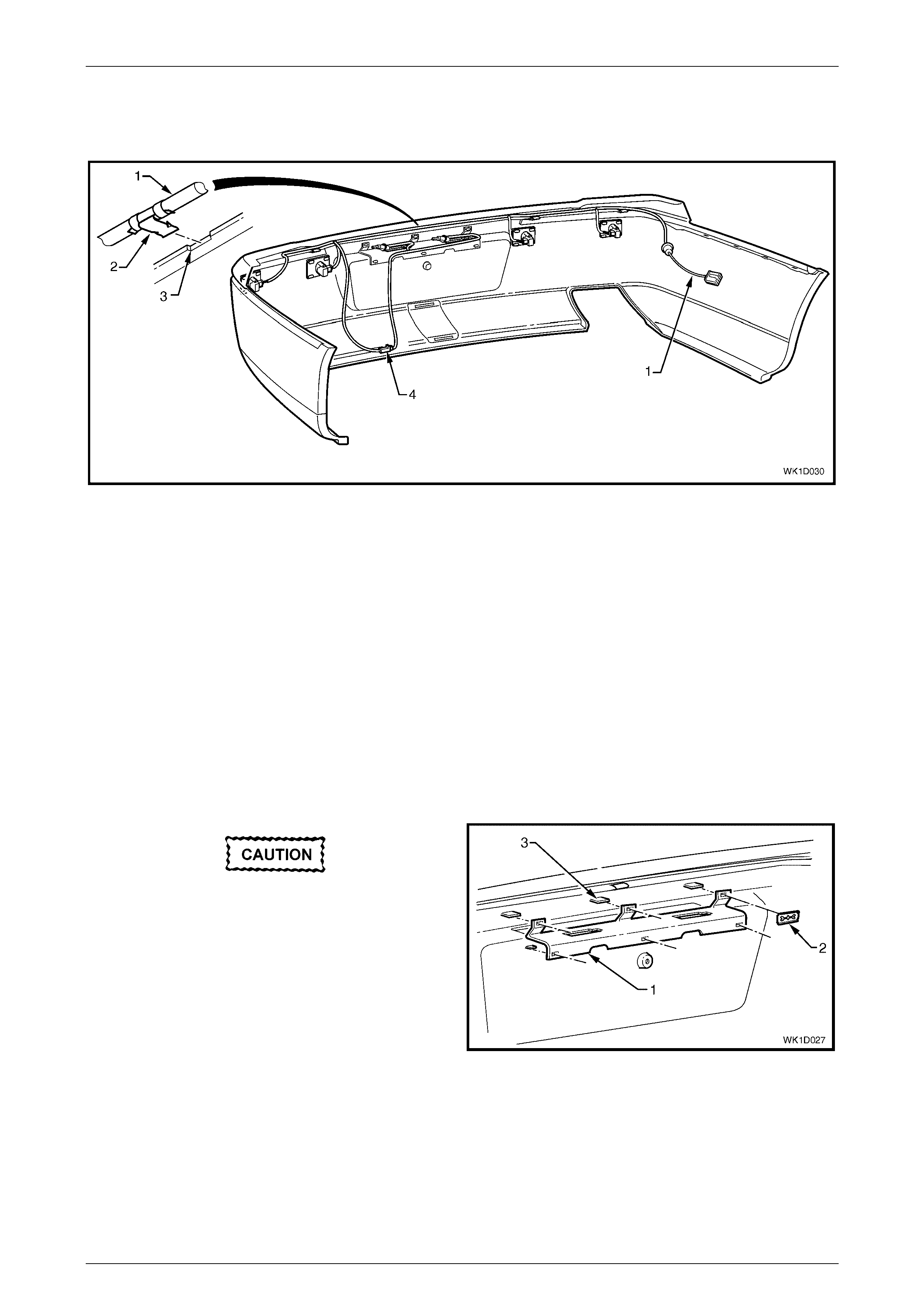
6 Disconnect the Reverse Parking Aid (RPA) or license plate light wiring harness connector from within the left-hand
side off the rear compartment.
7 With the aid of an assistant, withdraw the fascia
assembly and push the wiring harness and grommet
(1) through the side panel.
8 Remove the fascia assembly ensuring the seals (5,
Figure 1D – 11) remain with the fascia assembly.
Figure 1D – 12
Bumper Ba r s Page 1D–14
Page 1D–14
Disassemble
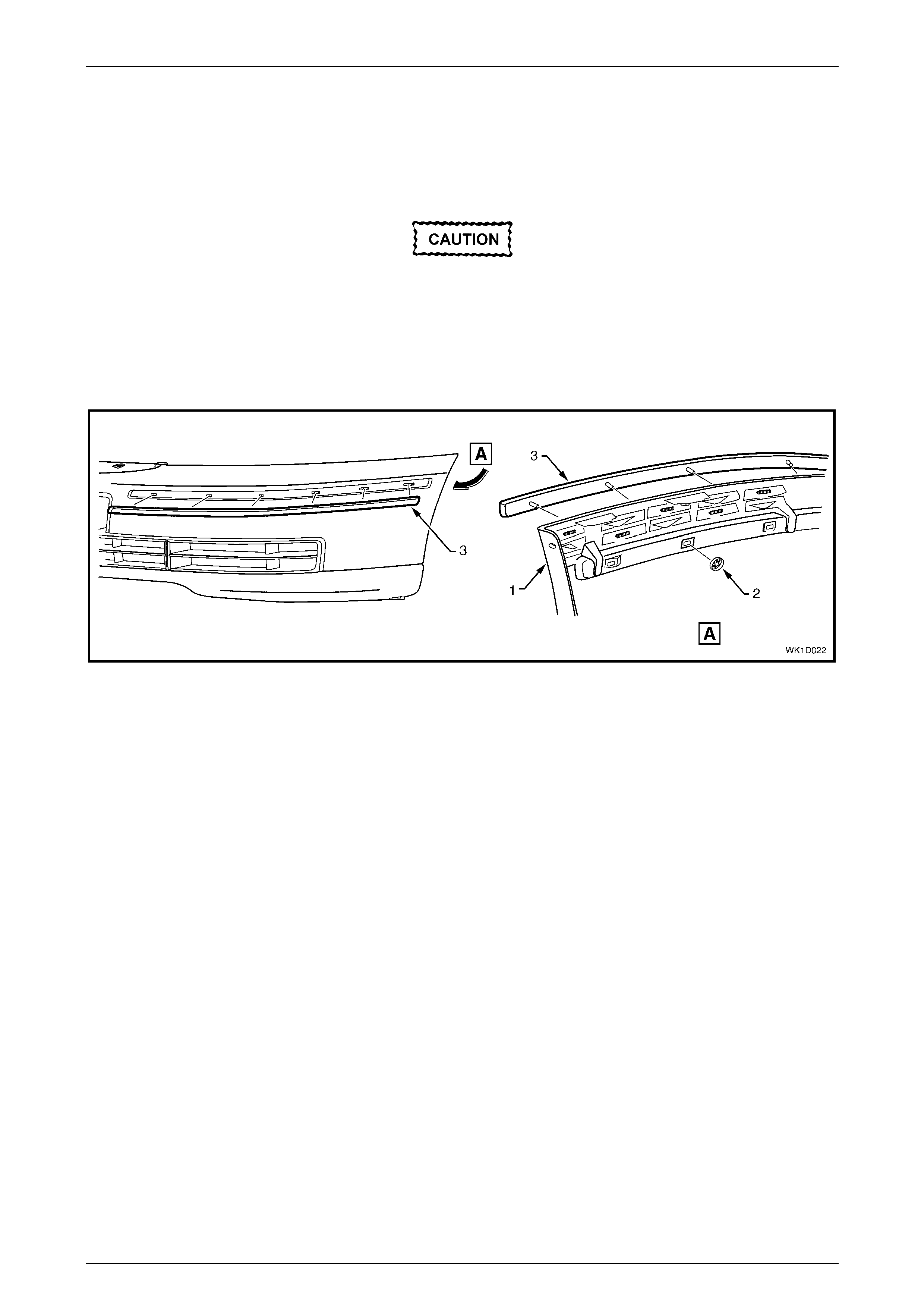
Rear Bumper Fascia Moulding
Remove
If the moulding is to be reused, take care as
the speed nuts can cut into and break the
lugs (4) during removal.
1 From the rear of the bumper fascia (1), remove the six
retaining speed nuts (2) securing the moulding (3) to
the bumper fascia.
2 Withdraw the moulding from the recess in the bumper
fascia.
Figure 1D – 13
Reinstall
1 Align and insert the corner lug of the moulding into the rear fascia. Working from the centre lug, insert each lug into
the rear fascia.
2 Fit a speed nut to the rear of each lug securely.
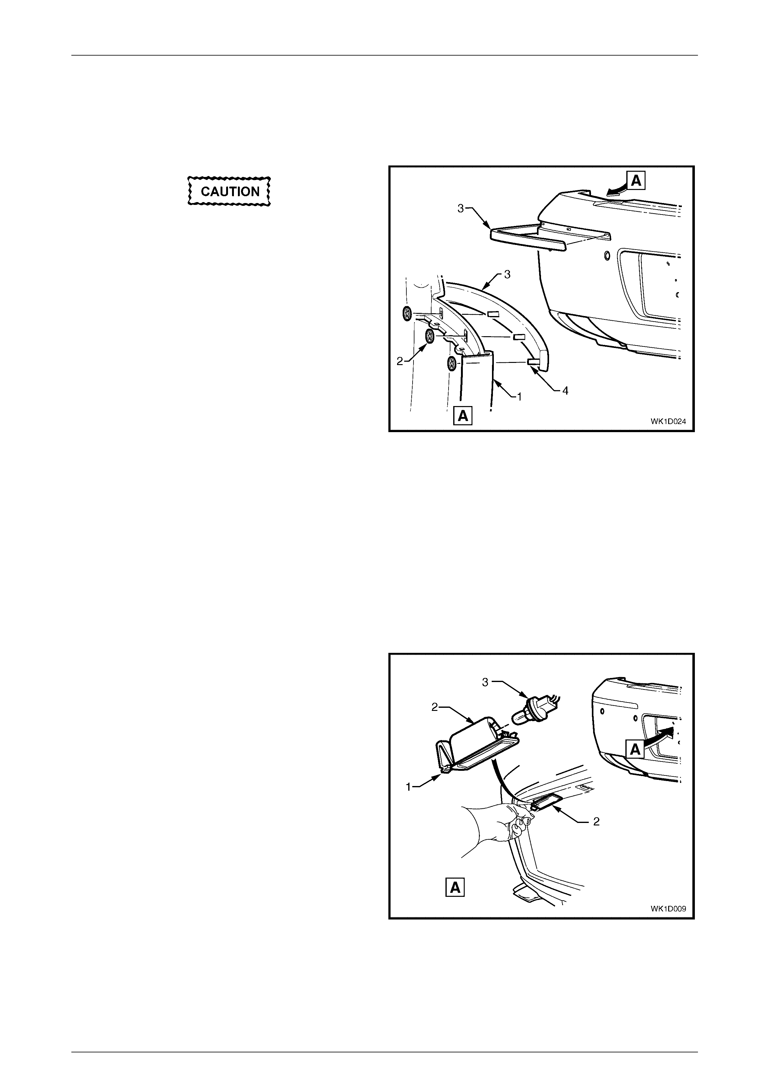
License Plate Lamp Assembly
Remove
Remove both lamp housings as follows:
1 Push the locking tang (1) located at the end of the
lamp housing (2) towards the lens. Pivot the housing
down and remove it from the aperture.
2 Remove the bulb socket (3) from the lamp housing.
Figure 1D – 14
Reinstall
1 Installation of the licence plate lamp assembly is the reverse of the removal procedure.
Bumper Ba r s Page 1D–15
Page 1D–15
License Plate Lamp Harness, Vehicles Without Reverse Park Aid
Remove
1 Remove both license plate lamp assemblies as previously described.
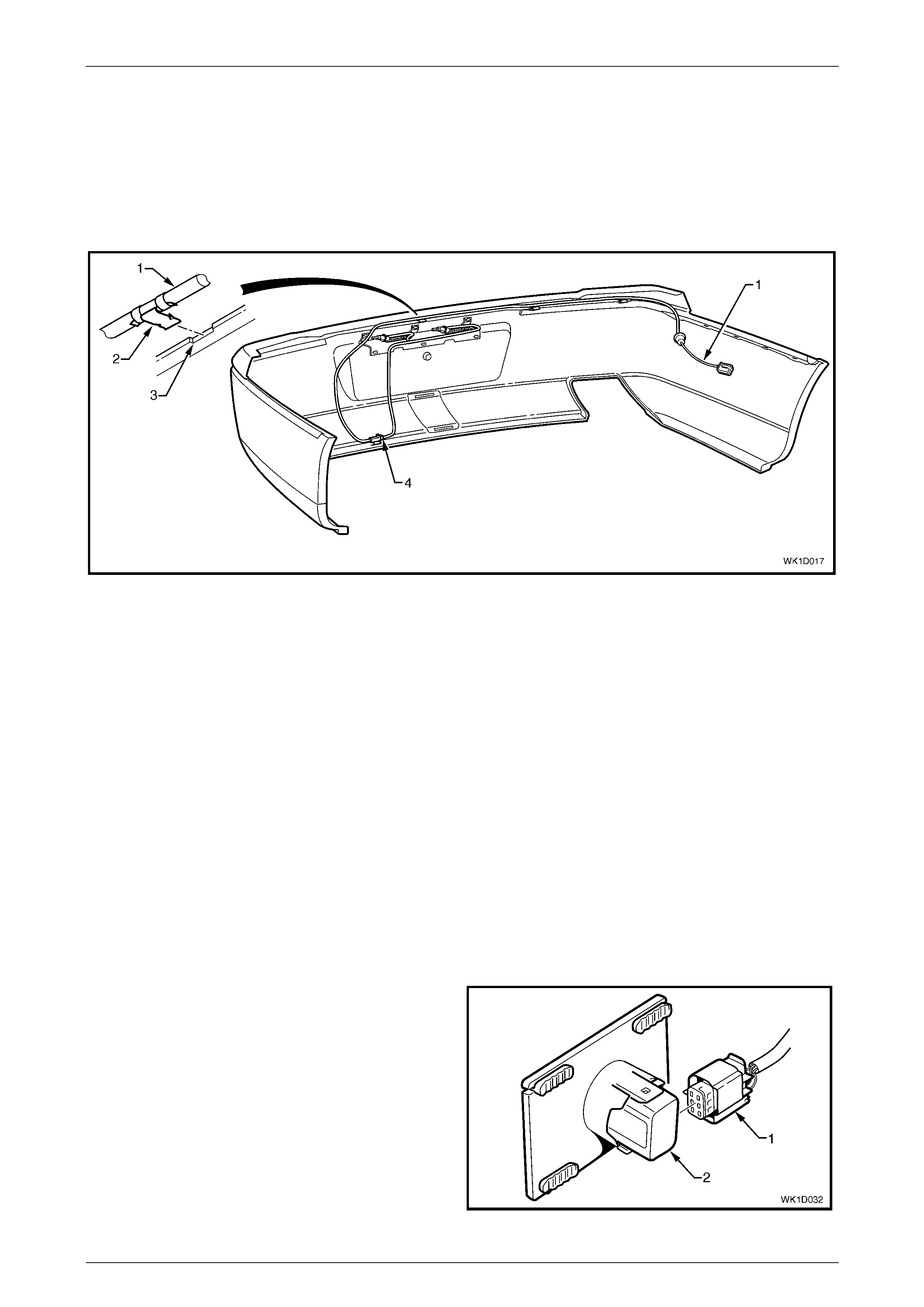
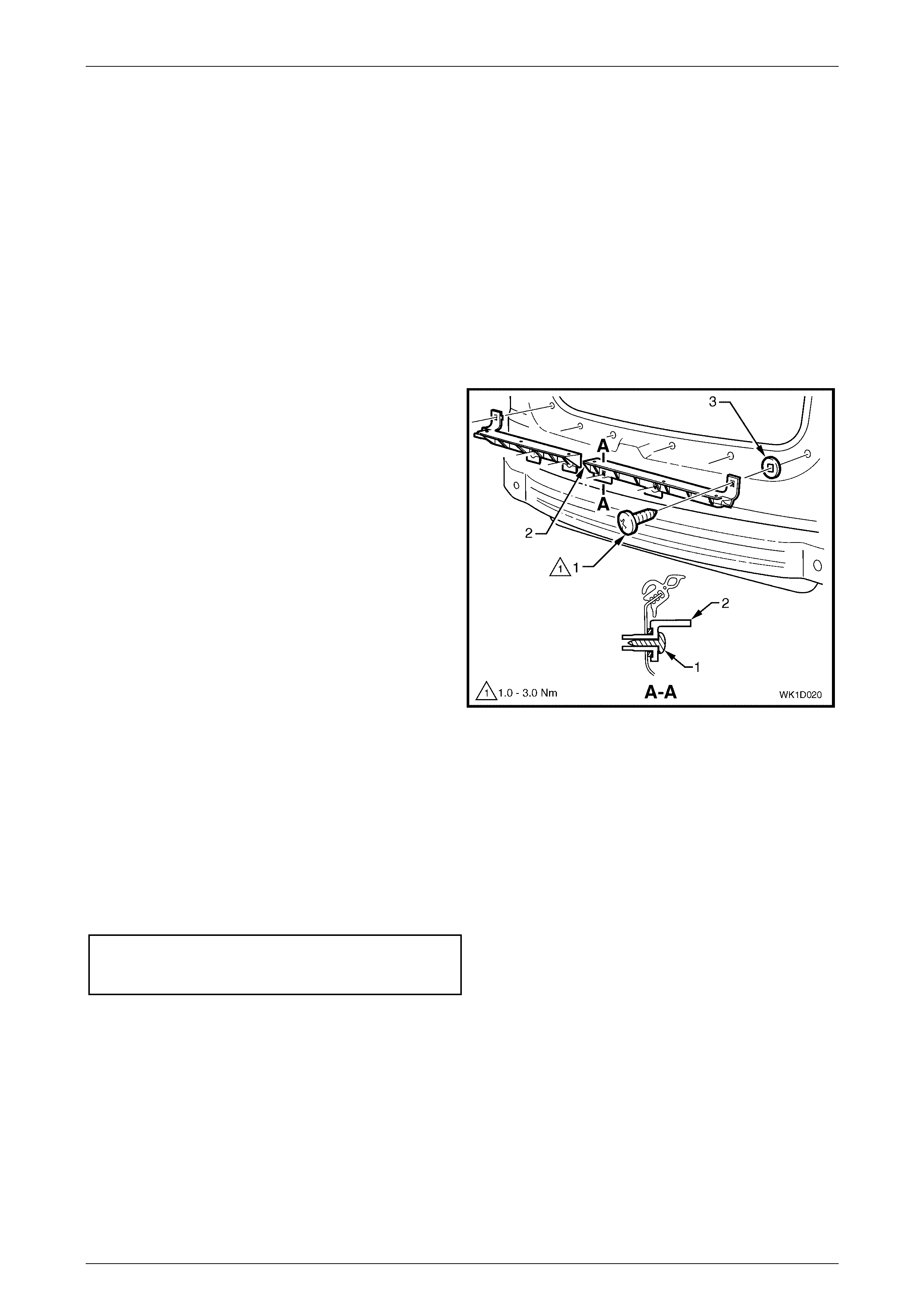
2 Remove the wiring harness (1) from the bumper fascia by prising the retaining clips (2), in three places, from the
bumper fascia with a fine flat blade screwdriver, refer to Figure 1D – 15.
3 Remove the connector (4) from the bumper fascia and remove the harness.
Figure 1D – 15
Reinstall
1 Route the wiring harness (1) to the left-hand side of the vehicle, refer to Figure 1D – 15.
2 Attach the harness, in three places, to the upper side of the bumper fascia rib, aligning each clip (2) at the
notch (3).
3 Attach the licence plate lamp harness connector (4) to the bumper fascia.
4. Install the license plate lamp assemblies as described in this Section.
License Plate Lamp Harness, Vehicles With Reverse Park Aid
NOTE
For Reverse Park Aid information refer to
Section 1D Bumper Bars in the MY 2003 VY and
V2 Series Service Information.
Remove
1 Remove both license plate lamp assemblies as described in this Section.
2 Remove the wiring harness connector (1) from the
rear object sensor assembly (2), in four places.
Figure 1D – 16
Bumper Ba r s Page 1D–16
Page 1D–16
3 Unclip the license plate lamp harness connector (4) from the bumper fascia, refer to Figure 1D – 17.
4 Remove the wiring harness from the bumper fascia by prising the three retaining clips (2) from the bumper
fascia (3) with a fine flat blade screwdriver.
Figure 1D – 17
Reinstall
1 Route the wiring harness (1) to the left-hand side of the vehicle, refer to Figure 1D – 17.
2 Attach the licence plate lamp harness connector (4) to the bumper fascia.
3 Attach the harness, in three places, to the upper side of the bumper fascia rib, aligning each clip (2) at the
notch (3).
4 Attach the wiring harness connector (1), in four places, to the rear object sensor assembly (2), refer to
Figure 1D – 16.
5. Install the license plate lamp assemblies as previously described.
License Plate Lamp Carrier, Except Level 4 RHD
Remove
If the fascia is to be reused, care must be
taken when removing the razor blade clips to
prevent damage to the lugs (3).
1 Remove the license plate lamp carrier (1) from the
bumper fascia by removing the razor blade retaining
clips (2), in six places, securing the license plate lamp
carrier (3) to the bumper fascia.
Figure 1D – 18
Reinstall
1 Position the license plate lamp carrier (1) onto the six lugs (3), ensuring it is seated against the fascia surface and
that the lugs correctly protrude through the holes, refer to Figure 1D – 18.
2 Fit a razor blade retaining clip (2), in six places, to the rear of each lug securely.
Bumper Ba r s Page 1D–17
Page 1D–17
License Plate Surround, Level 4 RHD
Remove
If the license plate surround is to be reused,
take care as the speed nuts can cut into and
break the lugs (4) during removal.
1 From the rear of the bumper fascia, remove the
retaining speed nuts (1), in 11 places, securing the
license plate surround (2) to the bumper fascia (3).
2 Withdraw the license plate surround from the bumper
fascia.
Reinstall
1 Fit the license plate surround into the bumper fascia,
locating the lugs in their respective holes.
2 Fit a speed nut to the rear of each lug securely.
Figure 1D – 19
Towbar Opening Cover
Remove
If the fascia is to be reused, take care as the
speed nuts can cut into and break the lugs (4)
during removal, refer to Figure 1D – 20.
1 From the rear of the bumper fascia, remove the retaining speed nut (1), in two places, securing the cover (2) to the
bumper fascia.
2 Depress the retaining tabs (3), in two places, and remove the towbar opening cover (2) from the bumper fascia (3).
Figure 1D – 20
Reinstall
1 Clip the towbar opening cover in place, taking care to align the cover with the bumper fascia guides (4 and 5).
Ensure that the two retaining tabs (3) are seated correctly. Refer to Figure 1D – 20.
2 Fit a speed nut to the rear of each lug securely.
Bumper Ba r s Page 1D–18
Page 1D–18
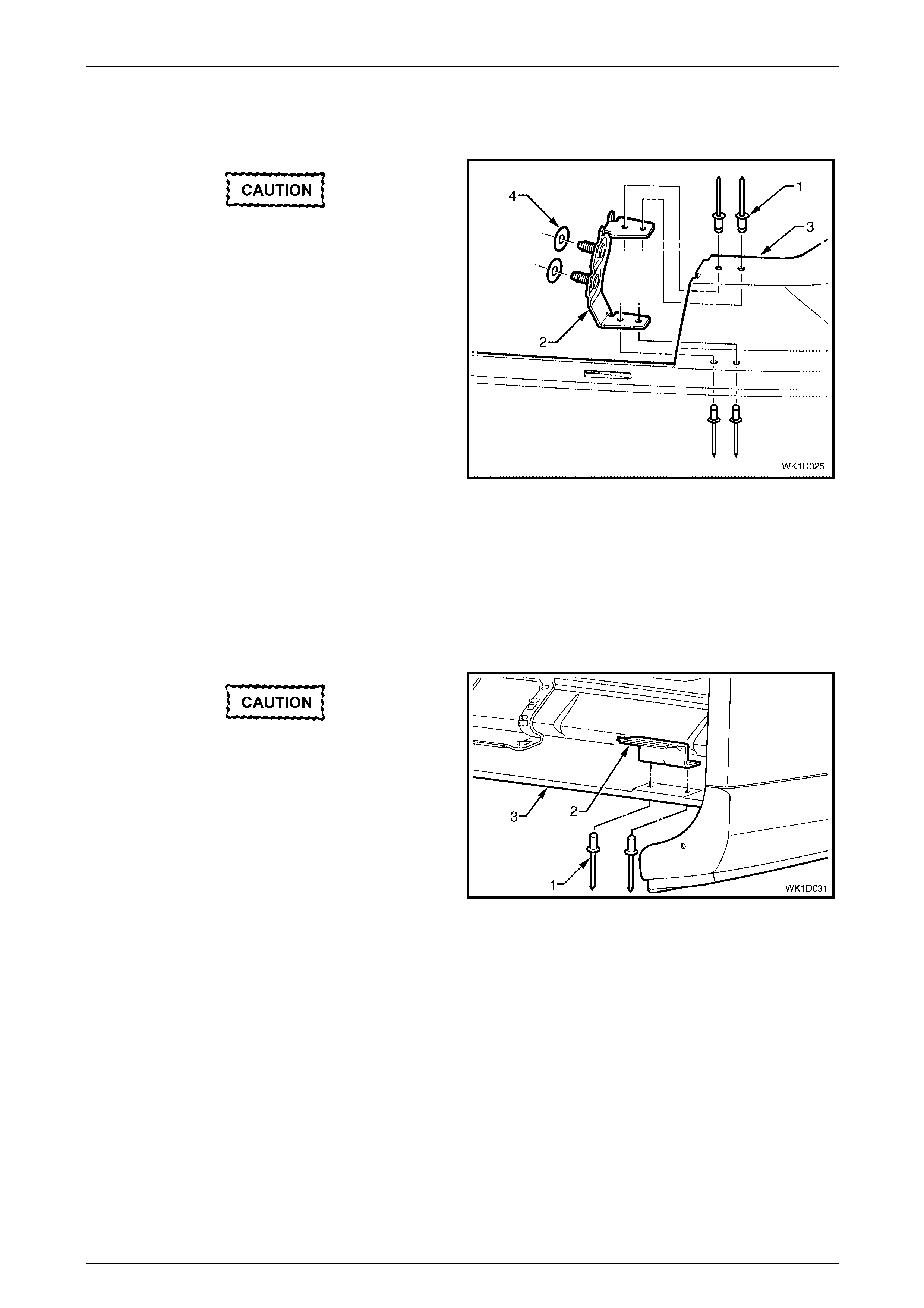
Rear Bumper Fascia Anchor Plate Assembly
Remove
If reusing the fascia assembly, take care not
to enlarge the rivet holes.
1 Using a 3mm drill-bit, remove the four rivets (1)
attaching the anchor plate assembly (2) to the fascia
assembly (3).
2 Remove the anchor plate assembly and if required the
two seals (4).
Figure 1D – 21
Reinstall
1 Using a rivet gun, rivet the anchor plate assembly, in four places, to the bumper fascia.
Rear Bumper Fascia Mounting Bracket Assembly
Remove
If reusing the fascia assembly, take care not
to enlarge the rivet holes.
1 Using a 3mm drill-bit, remove the two rivets (1)
attaching the fascia mounting bracket assembly (2) to
the fascia assembly (3).
2 Remove the fascia mounting bracket assembly.
Figure 1D – 22
Reinstall
1 Using a rivet gun, rivet the fascia mounting bracket assembly, in two places, to the bumper fascia.

Bumper Ba r s Page 1D–19
Page 1D–19
Reinstall
1 If the vehicle is fitted with a towbar remove the towbar opening cover.
2 Refinish the bumper fascia assembly in accordance with the procedures in 2.1 Paint System, Section 1D Bumper
Bars in the MY 2003 VY and V2 Series Service Information.
3 With the aid of an assistant, install the rear bumper fascia assembly onto the vehicle, inserting the RPA or license
plate lamp wiring harness connector, through its hole in the side panel, refer to Figure 1D – 12.
4 Securely fit the wiring harness grommet (1) into the side panel hole.
5 Install the two nuts (1) attaching the fascia assembly to the vehicle each side, refer to Figure 1D – 11. Do not
tighten.
6 Insert the four retainers (4) across the rear compartment lid opening.
7 Insert the two retainers (3) below the fascia assembly.
8 Align the side of the fascia assembly to the quarter panel and clip the fascia assembly into the rear bumper fascia
guide assembly (6), also ensuring the wheelhouse liner lug (7) for Level 1, 2, 4 & 5 vehicles is engaged into the
fascia, refer to Figure 1D – 10. Repeat for the opposite side.
9 Install the two screws each side (5), attaching the fascia assembly to the rear bumper fascia guide assembly (6)
and rear wheelhouse liner (4).
Rear bumper fascia assembly to rear
bumper fascia guide assembly attaching
screw torque specification.......................... 1.0 – 3.0 Nm
Rear bumper fascia assembly to
rear wheelhouse liner attaching
screw torque specification.......................... 1.0 – 3.0 Nm
10 If previously removed, reinstall the following components:
a Rear end trim panel, refer to Section 1A8, 4.12 Rear End Trim Panel in the MY 2003 VY and V2 Series Service
Information.
b Quarter inner rear side carpet, refer to Section 1A8, 2.17 Quarter Inner Rear Side Carpet.
11 Tighten the two nuts (1) attaching the fascia assembly on each side to the specified torque, refer to Figure 1D – 11.
Rear bumper fascia assembly
attaching nut torque
specification................................................6.0 – 9.0 Nm
12 If fitted, test the reverse parking aid for correct operation, refer to Section 12F Reverse Park Aid in the MY 2003
VY and V2 Series Service Information.
Bumper Ba r s Page 1D–20
Page 1D–20
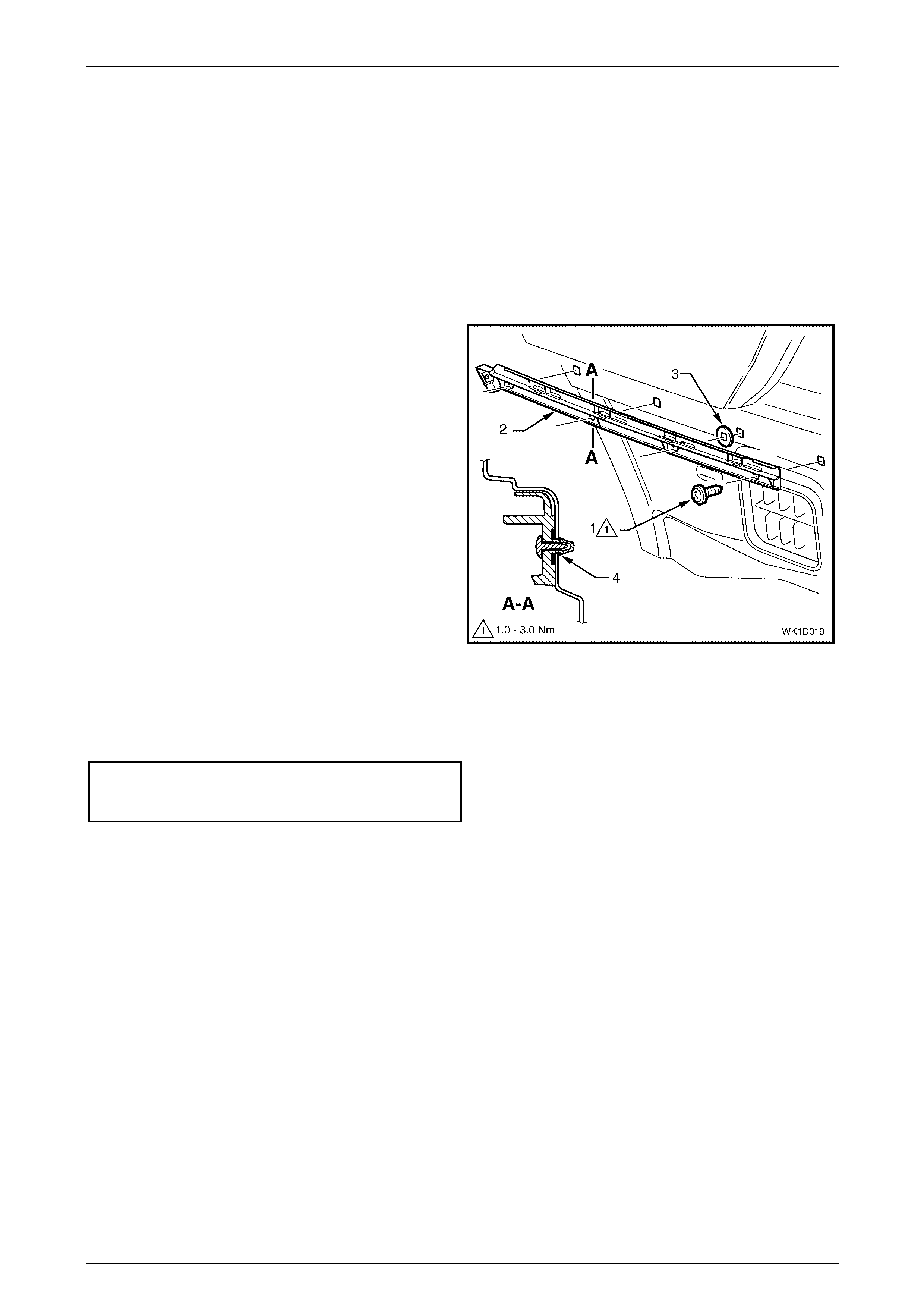
2.5 Rear Bumper Fascia Guide Assembly
Remove
1 Remove the rear bumper fascia, refer to 2.4 Rear Bumper Fascia Assembly.
NOTE
It may be possible to remove one side of the
bumper fascia and carefully move it out far
enough to gain access to the guide assembly.
2 Remove the screw (1), in four places, attaching the
guide assembly (2).
3 Prise the guide assembly out to detach it from the
vehicle.
NOTE
If required, remove the quarter inner rear side
carpet and using a fine flat-blade screwdriver,
depress the guide rail retaining tabs (4), in four
places. Refer to Section 1A8, 2.17 Quarter Inner
Rear Side Carpet for the rear side carpet
removal procedur e.
NOTE
Ensure the seal (3), in four places, is removed
with the guide assembly.
Figure 1D – 23
Reinstall
1 Installation is the reverse of removal. Tighten the screws to the specified torque.
Rear bumper fascia guide
assembly attaching screw
torque specific atio n ....................................1.0 – 3.0 Nm
Bumper Ba r s Page 1D–21
Page 1D–21
2.6 Rear Bumper Fascia Centre Support
Remove
There are two rear bumper fascia centre supports (2), with each being removed separately. The removal procedure for
both supports is identical.
1 Remove the rear bumper fascia assembly, refer to 2.4 Rear Bumper Fascia Assembly.
2. Remove the tail lamp assembly, refer to Section 12B, 2.8 Tail Lamp Assembly.
NOTE
It is only necessary to remove the tail lamp on the
side that the rear bumper fascia support is being
removed.
3 Remove the screw (1), in three places, attaching the
support (2) to the vehicle.
4 Prise the support from the vehicle
NOTE
Ensure the seal (3), in three places, is removed
with the centre support.
Figure 1D – 24
Reinstall
1 Installation is the reverse of removal.
NOTE
Ensure the seals are correctly fitted to the
support prior to installation. Tighten the screws to
the specified torque.
Rear bumper fascia centre
support attaching screw
torque specification .................................... 1.0 – 3.0 Nm

Bumper Ba r s Page 1D–22
Page 1D–22
3 Torque Wrench Specifications
Front fog and cornering lamp cover screw.....................................1.0 – 3.0 Nm
Front fog and cornering lamp assembly screw ..............................1.0 – 3.0 Nm
Front fog and cornering lamp metal strip bracket
attaching screws............................................................................1.0 – 3.0 Nm
Front bumper fascia assembly to front bumper fascia
guide assembly screw....................................................................1.0 – 3.0 Nm
Front bumper fascia assembly to front wheelhouse
liner screw......................................................................................1.0 – 3.0 Nm
Lower radiator grille attaching screw .............................................1.0 – 3.0 Nm
Rear bumper fascia assembly to rear bumper fascia
guide assembly screw....................................................................1.0 – 3.0 Nm
Rear bumper fascia assembly attaching nut..................................6.0 – 9.0 Nm
Rear bumper fascia assembly to rear wheelhouse
liner screw......................................................................................1.0 – 3.0 Nm
Rear bumper fascia centre su pport screw .....................................1.0 – 3.0 Nm
Rear bumper fascia guide ass embly screw...................................1.0 – 3.0 Nm