
Wheels and Tyres Page 10–1
10–MAR–2003 Page 10–1
Section 10
Wheels and Tyres
ATTENTION
Before performing any Service Operation or other procedure described in this Section, refer to Section 00
WARNINGS, CAUTIONS AND NOTES for correct workshop practices with regard to safety and/or property
damage.
1 General Information............................................................................................................................... 2
1.1 Wheel and Tyre Combinations..............................................................................................................................2
1.2 Tyre Placards..........................................................................................................................................................5
1.3 Tyre Markings.........................................................................................................................................................6
1.4 Spare Wheel Stowage............................................................................................................................................7
2 Specifications......................................................................................................................................... 8
3 Torque Wrench Specifications............................................................................................................. 9
4 Special Tools........................................................................................................................................ 10
Techline
Wheels and Tyres Page 10–2
10–MAR–2003 Page 10–2
1 General Information
New wheels and wheel covers have been introduced for the MY2004 WK Series vehicles. This Section provides
information of the recommended wheels and tyres for the right-hand drive and left-hand drive range of vehicles.
Right-hand Drive Vehicles — Domestic
Right-hand Drive Vehicles — Domestic
Holden
Level 4 Level 5
Statesman Sedan Caprice Sedan
Left-hand Drive Vehicles — Export
Chevrolet
Level 1 Level 2 Level 2 Sport Level 5
Caprice LS
Sedan Caprice LTZ
Sedan Caprice SS
Sedan Royale
Sedan
1.1 Wheel and Tyre Combinations
Figure 10-1 illustrates the silver steel wheel (1) and
centre cap (2) fitted to the following vehicle:
LEFT-HAND DRIVE
Caprice LS Sedan
Road wheels............................. 7J x 15
Tyres ........................................ 225/60R15 96V
Figure 10-1

Wheels and Tyres Page 10–3
10–MAR–2003 Page 10–3
Figure 10-2 illustrates the alloy wheel for the left-hand
drive Chevrolet Caprice and right-hand drive Holden
Statesman:
LEFT-HAND DRIVE
Chevrolet Caprice LTZ
Road Wheels............................ 7JJ x 16 alloy
Tyres ........................................ 225/55R16 94V
Option – Chevrolet Caprice LS
Road Wheels............................ 7JJ x 16 alloy
Tyres ........................................ 225/55R16 94V
RIGHT-HAND DRIVE
Holden Statesman
Road Wheels............................ 7JJ x 16 alloy
Tyres ........................................ 225/55R16 95V
Figure 10-2
Figure 10-3 illustrates the alloy wheel fitted to the
Chevrolet Caprice SS Sedan.
LEFT-HAND DRIVE
Chevrolet Caprice SS Sedan
Road Wheels............................ 8JJ x 17 alloy
Tyres ........................................ 235/45R17 93V
Figure 10-3
Figure 10-4 illustrates the alloy wheel fitted to the Holden
Caprice.
RIGHT-HAND DRIVE
Holden Caprice Sedan
Road Wheels............................ 8JJ x 17 alloy
Tyres ........................................ 225/50R17 94V
Figure 10-4

Wheels and Tyres Page 10–4
10–MAR–2003 Page 10–4
Figure 10-5 illustrates the alloy wheel fitted to the
Chevrolet Royale.
LEFT-HAND DRIVE
Chevrolet Royale Sedan
Road Wheels............................ 7JJ x 16 alloy
Tyres ........................................ 225/55R16 94V
Figure 10-5
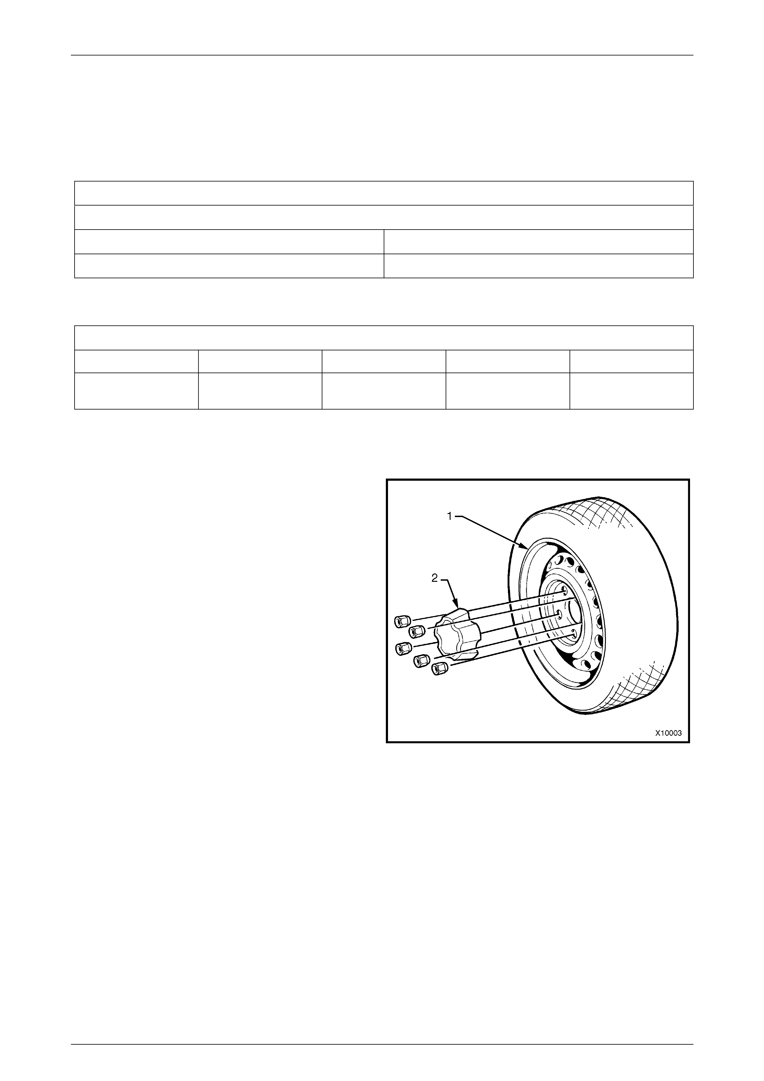
Figure 10-6 illustrates the black steel wheel (1), wheel
nuts (2) and wheel trim (3) for Chevrolet Caprice LS:
LEFT-HAND DRIVE
Chevrolet Caprice LS
Road Wheels............................ 7J x 15
Tyres:
V8 Engine................................. 225/60R15 96V
Figure 10-6
Wheels and Tyres Page 10–5
10–MAR–2003 Page 10–5
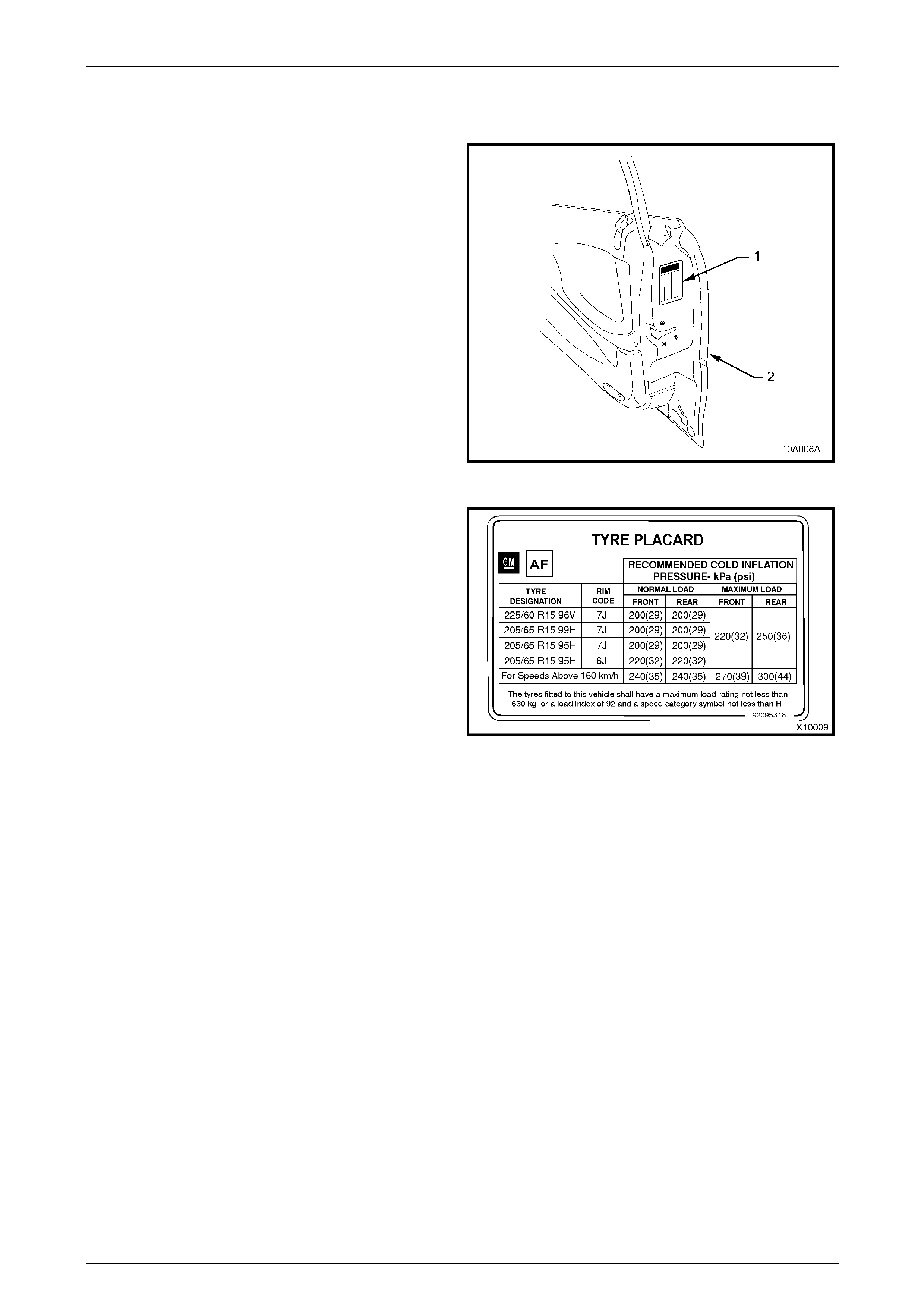
1.2 Tyre Placards
Wheel and tyre sizes, inflation pressures and load
capacity are specified on a tyre placard (1) located on
the end surface of the driver door (2), refer to Fig. 10-8
(Right-hand Drive shown).
Always check tyre pressures, with COLD tyres (after
vehicle has stood for three hours or more, or driven less
than 2 km) and should be checked weekly or before any
extended trip.
When checking ty re pressur e, v isual ly inspect tyres for
excessive wear, sharp objects embedded in the tyre or
damage to the sidewalls.
NOTE 1: Clean valve exterior, prior to applying air
pressure nozzle when inflating tyre.
NOTE 2: Always install valve caps to keep out dust and
water.
Figure 10-7
The tyre placard shown in Fig. 10-8 is typical of those
fitted on the vehicle.
Refer to 2. SPECIFICATIONS in this Section or the Tyre
Placard on the driver’s door for the correct wheel and
tyre size and tyre pressures.
Figure 10-8
Wheels and Tyres Page 10–6
10–MAR–2003 Page 10–6
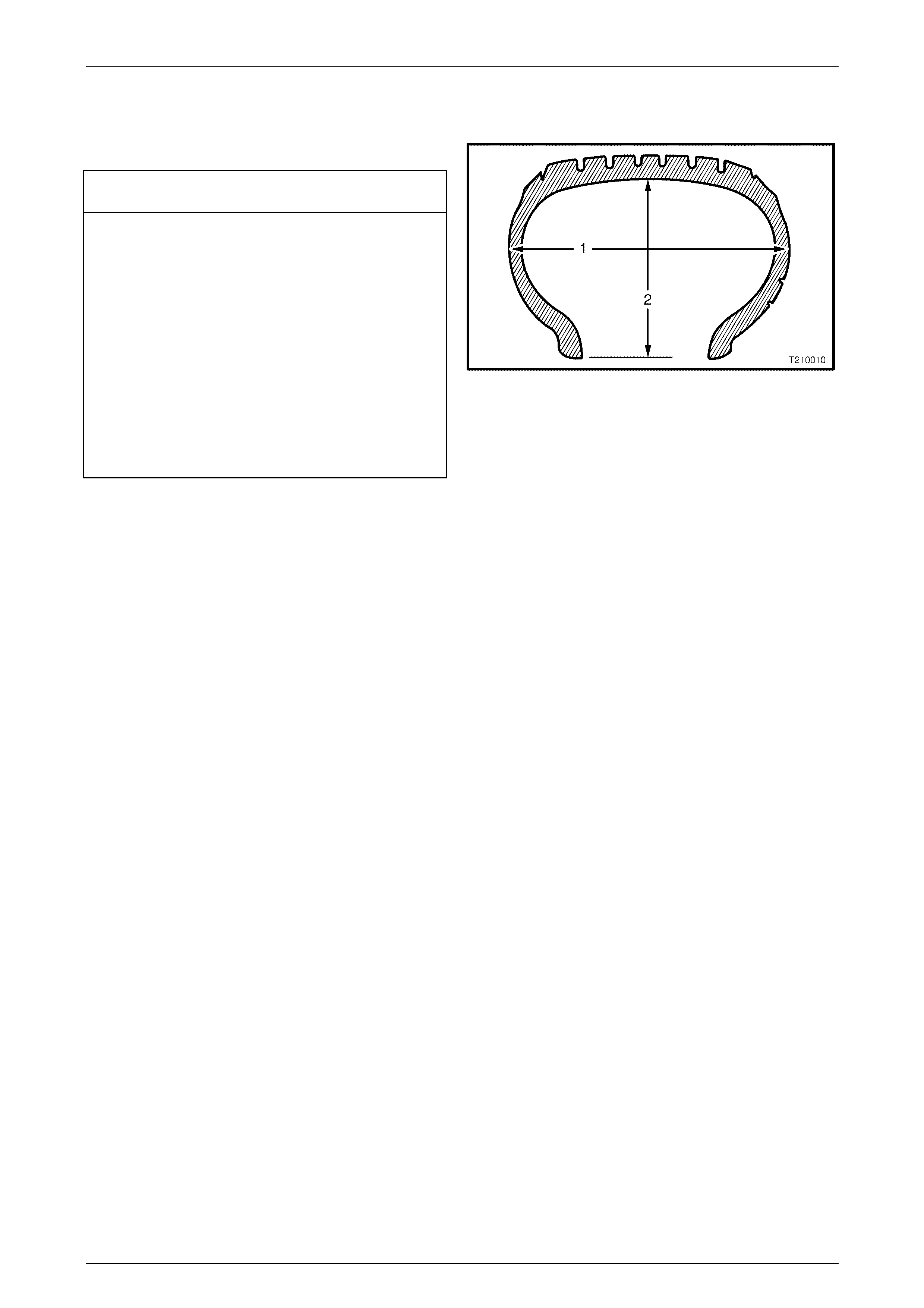
1.3 Tyre Markings
The tyre sidewall has a coded marking system, which
provides information about the tyre.
Tyre Marking Example:
225 55 R 16 95 V
225 = Section Wi dth (1) – mm (225 mm)
55 = Aspect Ratio % (Section Height (2) to Section
Width (1) (55 = 55%)
R = Tyre Construction (R = Radial)
16 = Rim Diameter – inches (16 = 16”)
95 = Load Index – kg (91 = 615 kg m ax. load)
(92 = 630 kg max. load)
(93 = 650 kg max. load)
(94 = 670 kg max. load)
(95 = 690 kg max. load)
(96 = 710 kg max. load)
(99 = 775 kg max. load)
V = Speed Rating (H = 210 km/h)
(V = 240 km/h)
(W = 270 km/h)
Figure 10-9
Wheels and Tyres Page 10–7
10–MAR–2003 Page 10–7
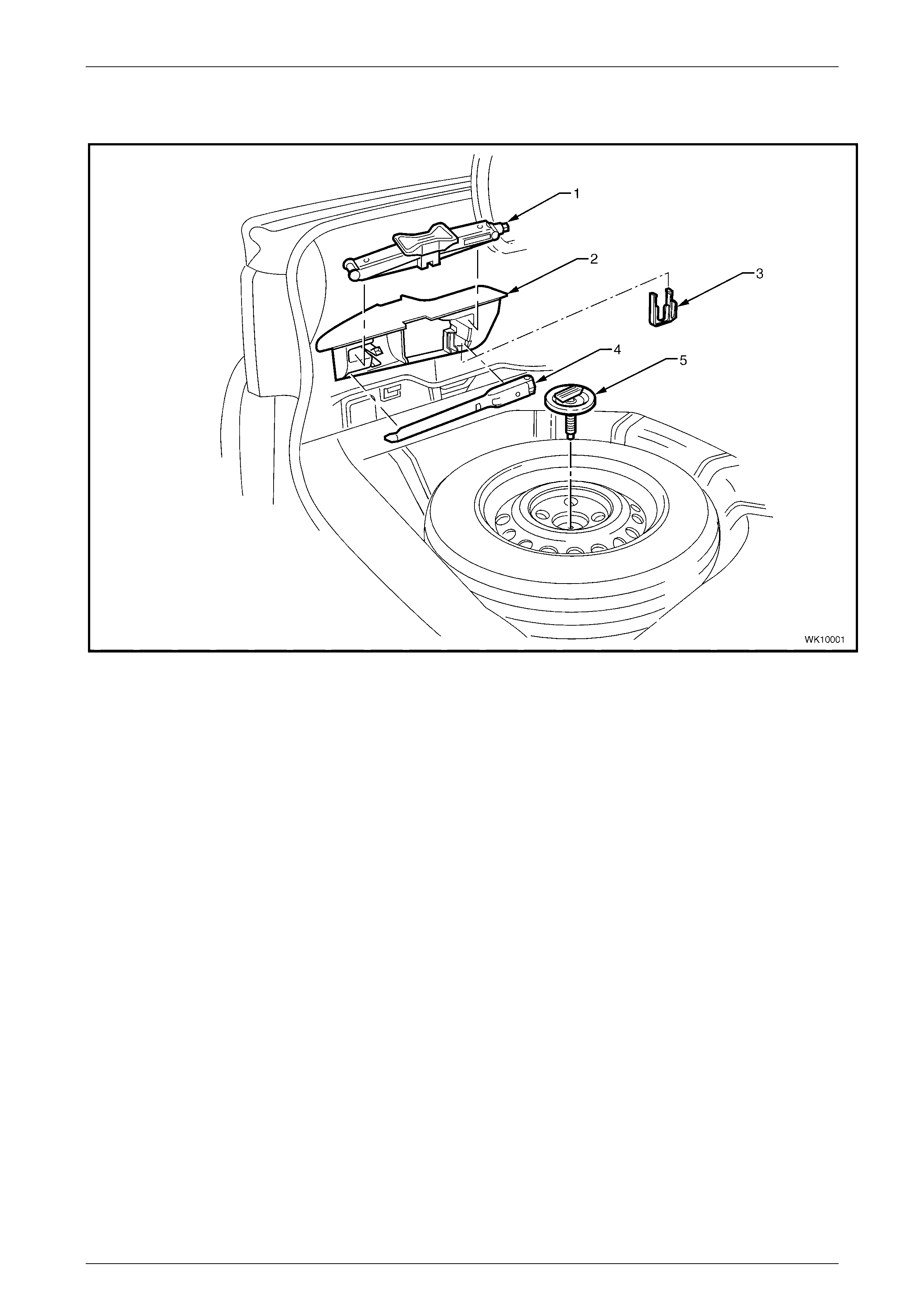
1.4 Spare Wheel Stowag e
Figure 10-10 Spare Wheel and Jack Stowage
Legend
1. Jack 4. Jack/Wheel Nut Wrench
2. Stowage Compartment 5. Spare Wheel Retaining Bolt and Plate
3. Nut Cap Removal Tool
For Service Information and Diagnosis of the Wheels and Tyres for the MY2004 WK Series vehicles, refer to Section 10
WHEELS AND TYRES for the MY2003 VY and V2 Series vehicles.
Wheels and Tyres Page 10–8
10–MAR–2003 Page 10–8
2 Specifications
STEEL WHEELS
Rim Width Code.................................................................... 6J 7J
Diameter Code...................................................................... 15 15
Maximum Permissible Radial Run-out
All Steel Wheels .............................................................. 0.8 mm
Maximum Permissible Lateral Run-out
All Steel Wheels .............................................................. 0.8 mm
Offset..................................................................................... 43 mm (positive)
ALLOY WHEELS
Rim Width Code.................................................................... 7J 7JJ 8JJ
Diameter Code...................................................................... 16 16 17
Maximum Permissible Radial Run-out
All models........................................................................ 0.4 mm
Maximum Permissible Lateral Run-out
All models........................................................................ 0.4 mm
Offset
All models........................................................................ 48 mm (positive)
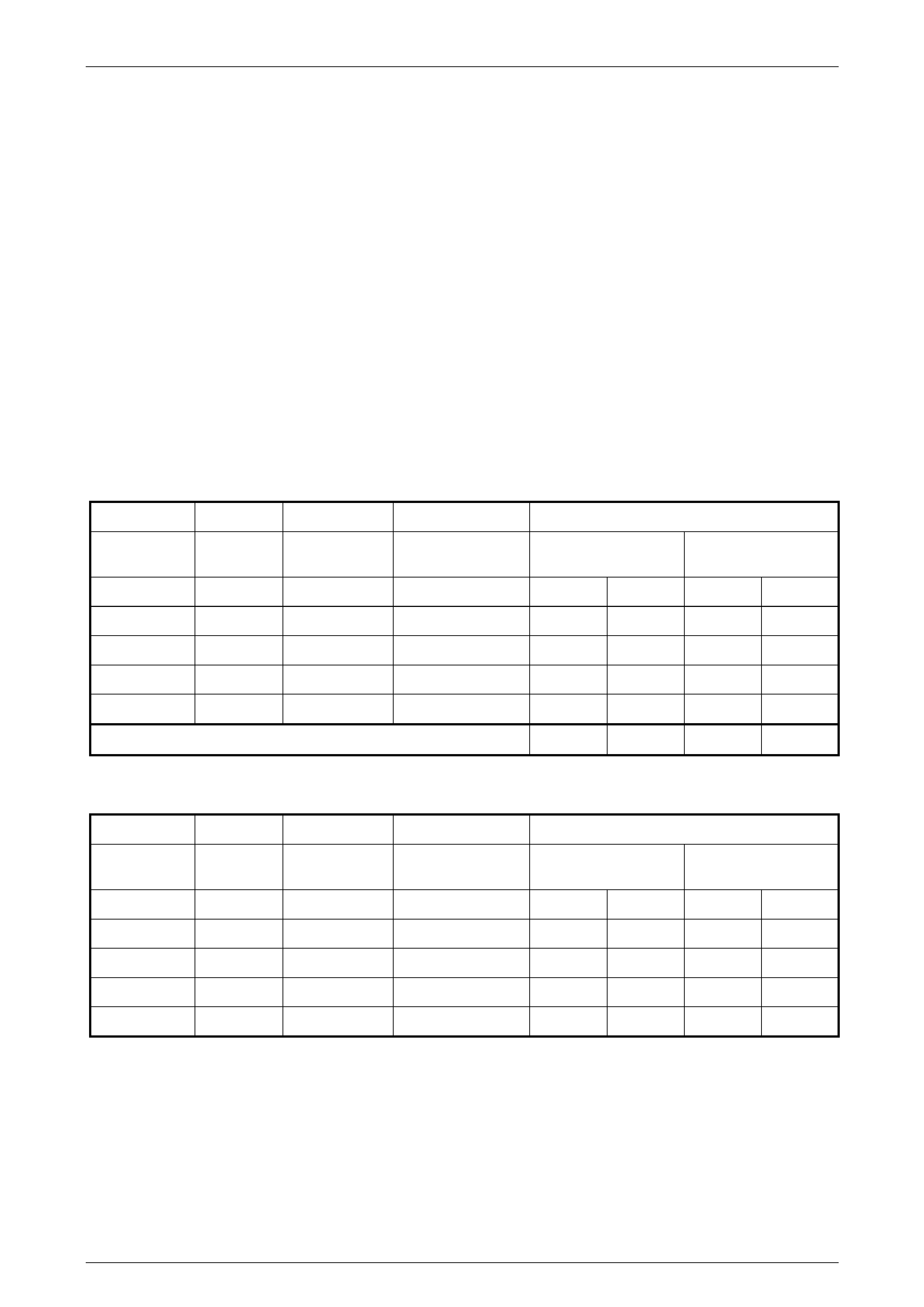
INFLATION PRESSURES
Australia and South Africa
RECOMMENDED COLD INFLATION – kPa
MODEL ENGINE WHEEL TYRE
DESIGNATION Up to 3 Passengers Up to Max. Load
Front Rear Front Rear
Sedan V6/V6 S/C 7JJ x 16 Alloy 225/55 R16 95V 200 200 220 250
V6 8JJ x 17 Alloy 225/50 R17 94V 200 200 220 250
Sedan V8 7JJ x 16 Alloy 225/55 R16 95V 200 200 220 250
V8 8JJ x 17 Alloy 225/50 R17 94V 200 200 220 250
For speeds above 160 km/h 240 240 270 300
Gulf States
RECOMMENDED COLD INFLATION – kPa
MODEL ENGINE WHEEL TYRE
DESIGNATION Up to 3 Passengers Up to Max. Load
Front Rear Front Rear
Sedan V6/V8 7J x 15 Steel 225/60 R15 96W 230 230 270 310
V6 7JJ x 16 Alloy 225/55 R16 94V 230 230 270 310
Sedan V8 7JJ x 16 Alloy 225/55 R16 94V 230 230 270 310
V8 8JJ x 17 Alloy 235/45 R17 93V 230 230 270 310

Wheels and Tyres Page 10–9
10–MAR–2003 Page 10–9
3 Torque Wrench Specifications
Road Wheel Attaching Nuts (All Wheels).....................................110 – 140 Nm

Wheels and Tyres Page 10–10
10–MAR–2003 Page 10–10
4 Special Tools
Tool Number Illustration Description Classification
AU534
TOR QUE L IMITING SOCKET
Released to allow the use of impact
gun to tighten road wheel nuts
Mandatory