
Lighting Syst em Page 12B–1
Page 12B–1
Section 12B
Lighting System
ATTENTION
Before performing any Service Operation or other procedure described in this Section, refer to Section 00
Warnings, Cautions And Notes for correct workshop practices with regard to safety and/or damage.
1 General Description............................................................................................................................... 3
1.1 Headlamp Assembly..............................................................................................................................................3
1.2 Side Repeater Lamp Assembly.............................................................................................................................5
1.3 Fog and Cornering Lamp Assembly.....................................................................................................................6
1.4 Tail Lamp Assembly...............................................................................................................................................7
1.5 Hazard Warning Switch .........................................................................................................................................8
1.6 Interior Illumination................................................................................................................................................9
1.7 Instrument and Switch Illumination....................................................................................................................10
2. Servic e Oper ations – Exterior Illumination....................................................................................... 11
2.1 Front Fog Lamp Aiming.......................................................................................................................................11
Front Fog Lamp Aim ............................................................................................................................................11
2.2 Front Fog Lamp Bulb...........................................................................................................................................13
Replace .................................................................................................................................................................13
2.3 Front Cornering Lamp Bulb.................................................................................................................................14
Replace .................................................................................................................................................................14
2.4 Fog and Cornering Lamp Harness......................................................................................................................15
Remove .................................................................................................................................................................15
Reinstall ................................................................................................................................................................15
2.5 Tail Lamp Assembly Bulbs..................................................................................................................................16
Replace .................................................................................................................................................................16
2.6 Headlamp Assembly............................................................................................................................................17
Remove .................................................................................................................................................................17
Reinstall ................................................................................................................................................................18
2.7 Fog and Cornering Lamp Assembly...................................................................................................................19
Remove .................................................................................................................................................................19
Reinstall ................................................................................................................................................................19
2.8 Tail Lamp Assembly.............................................................................................................................................20
Remove .................................................................................................................................................................20
Reinstall ................................................................................................................................................................21
2.9 Rear License Plate Lamp Assembly...................................................................................................................22
Remove .................................................................................................................................................................22
Reinstall ................................................................................................................................................................22
2.10 Rear Licence Plate Wiring Harness....................................................................................................................23
3 Service Operations – Interior Illumination and Switching............................................................... 24
3.1 Hazard Warning Switch Assembly......................................................................................................................24
Level 1...................................................................................................................................................................24
Level 2 to 5............................................................................................................................................................24
Remove............................................................................................................................................................24
Reinstall............................................................................................................................................................25
Test...................................................................................................................................................................26
3.2 Hazard Warning Switch Bulb...............................................................................................................................27
Level 1...................................................................................................................................................................27
Level 2 to 5............................................................................................................................................................27
Replace ............................................................................................................................................................27
Techline
Techline

Lighting Syst em Page 12B–2
Page 12B–2
3.3 Rear Vanity Mirror Lamp Bulbs...........................................................................................................................28
Replace .................................................................................................................................................................28
3.4 Rear Remote Control Bulbs.................................................................................................................................30
Replace .................................................................................................................................................................30
4 Specifications....................................................................................................................................... 31
5. Torque Wrench Specifications........................................................................................................... 32

Lighting Syst em Page 12B–3
Page 12B–3
1 General Description
With the following exceptions, MY 2004 WK Series Lighting System information carries over from MY 2003 VY Series
vehicles. For information not contained within this Section, refer to Section 12B Lighting System in the MY 2003 VY and
V2 Series Service Information.
Headlamp Assembly:
• Similar to VY sedan headlamp assembly except for revised chrome or black headlamp bezels used to suit WK
styling.
Tail lamp Assembly:
• Revised styling and fitment.
Fog and Cornering Lamp Assembly:
• New fog and cornering lamp assembly fitted to front bumper fascia.
Side Repeater Lamp Assembly:
• Revised to incorporate chrome plated bulb shield.
Interior Illumination:
• Carry over from VY sedan with additional rear vanity mirror lighting.
Instrument and Switch Illumination:
• For Level 2 – 5 vehicles, the hazard switch is relocated from the centre fascia to the console.
• The rear remote control is fitted to Level 5 vehicles.
The information that is provided in this
Section is to be used for both left and right-
hand drive vehicles. Although the information
shown is primarily right-hand drive, it is to be
mirrored for left-hand drive vehicles unless
otherwise specified.
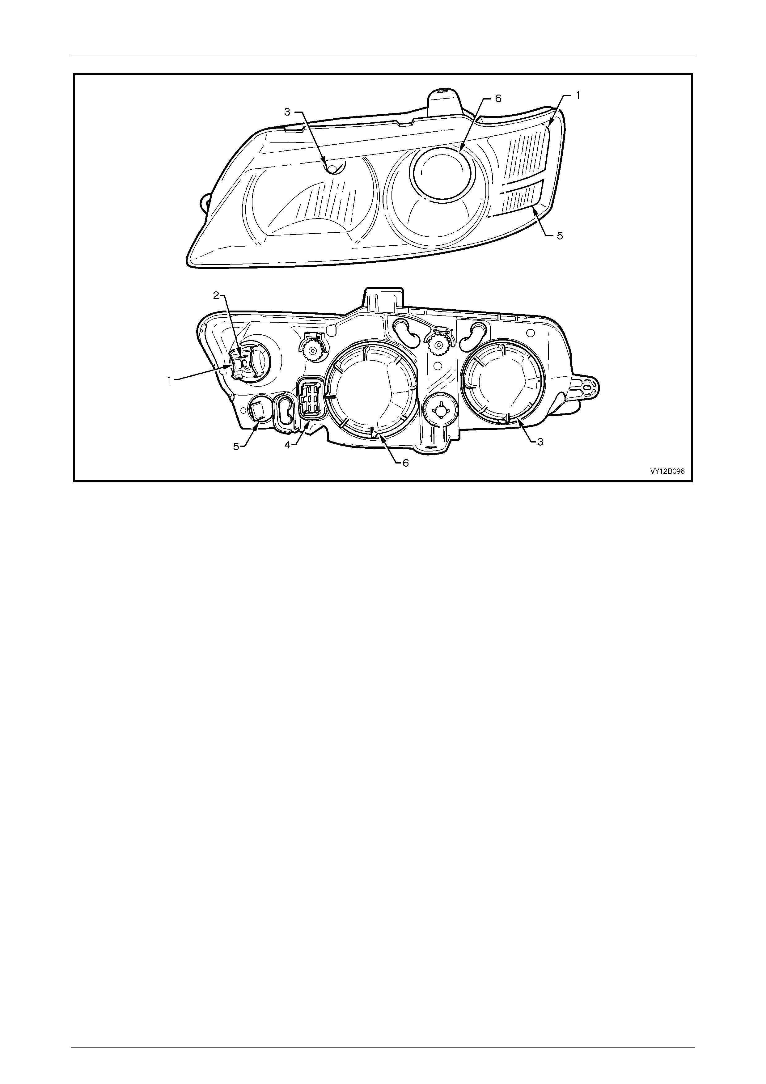
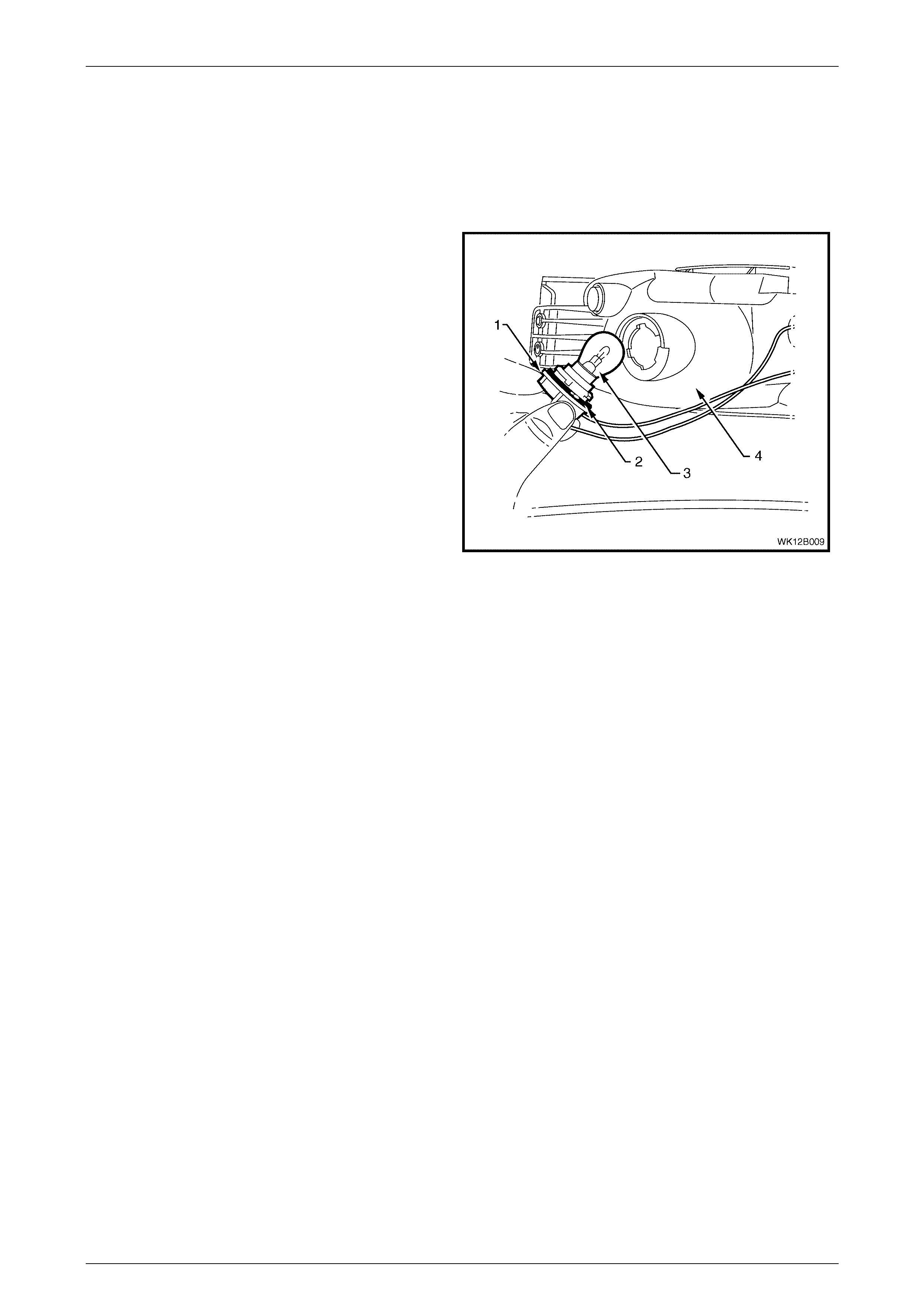
1.1 Headlamp Assembly
The headlamp assemblies fitted to WK Series vehicles incorporate a pair of semi-sealed, dual pocket, homofocal
headlamps. The high beam lamp, located towards the inboard edge of the headlamp assembly, incorporates a H9
specification quarts halogen bulb. The low beam lamp, located outboard of the high beam lamp, uses projector unit
technology in conjunction with a H11 specification globe to provide optimum illumination characteristics.
The turn signal lamp and parking lamps are integrated along the outboard edge of each headlamp assembly. The turn
signal lamp is positioned above the park lamp and incorporates an orange tinted glass bulb and a clear appearance lens.
The park lamp incorporates an untinted glass bulb and a clear appearance lens. Chrome or black headlamp bezels have
been fitted within the headlamp assemblies to provide distinctive styling between the various WK Series model levels.
NOTE
For vehicles fitted with the daylight running lamp
feature (option T82), operation of the front
headlamps will occur while the ignition switch is
on.
Lighting Syst em Page 12B–4
Page 12B–4
Figure 12B – 1
Legend
1 Turn Signal Lamp
2 Turn Signal Wiring Connector 3 Headlamp High Beam
4 Headlamp Wiring Connector 5 Park Lamp
6 Headlamp Low Beam

Lighting Syst em Page 12B–5
Page 12B–5
1.2 Side Repeater Lamp Assembly
A turn signal side repeater lamp is fitted to both the right and left front fender panels, aft of the front wheel arch. The lamp
assembly incorporates a chrome plated bulb shield, orange tinted glass bulb, reflector and clear appearance lens.
Lighting Syst em Page 12B–6
Page 12B–6
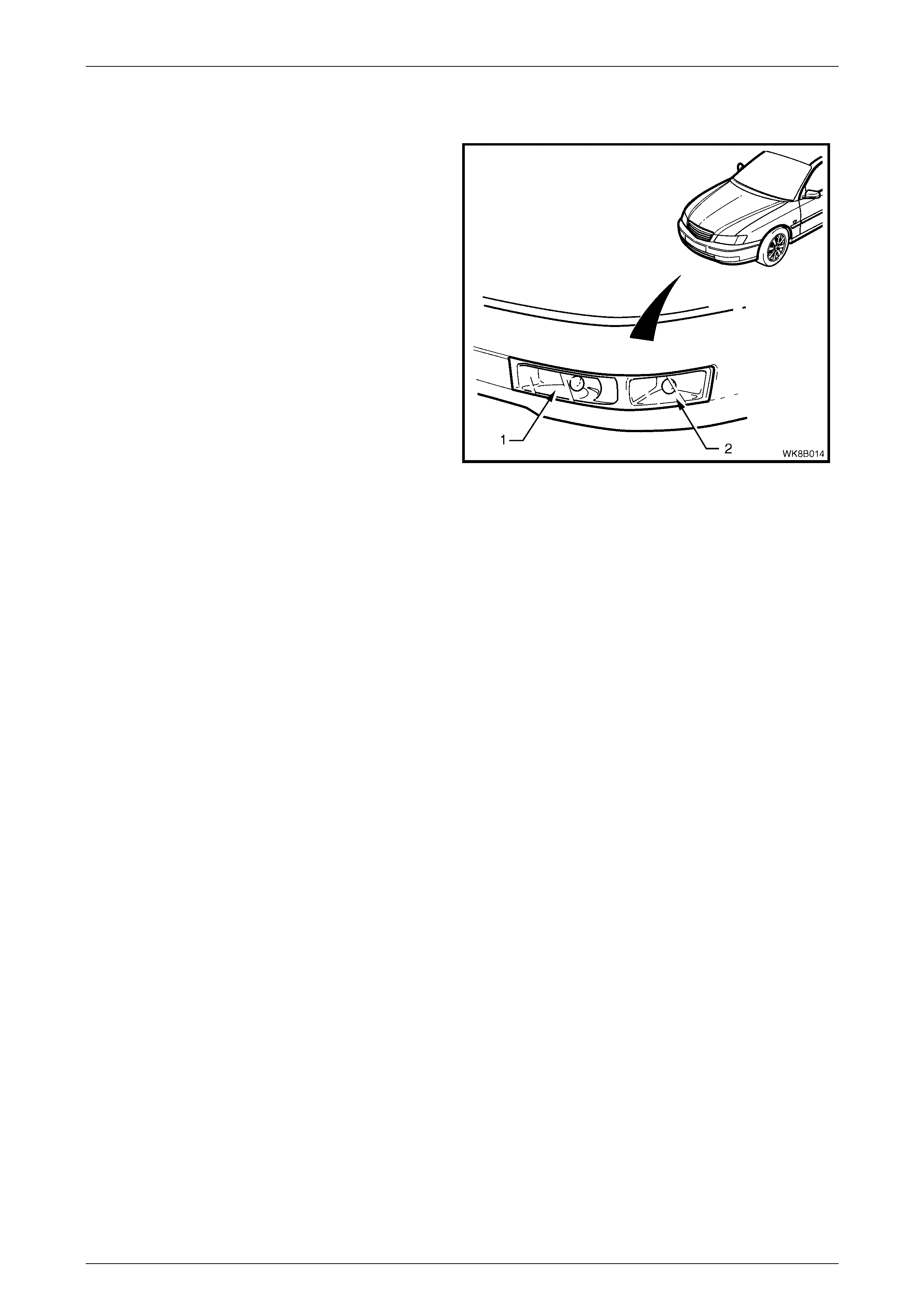
1.3 Fog and Cornering Lamp Assembly
Fog and cornering lamp assemblies are fitted to the front
bumper fascia, directly below each headlamp assembly.
NOTE
On some vehicles a metal strip bracket may be
attached to the lamp housing to ensure rigidity
and reinforce the interface with the front bumper
fascia. Razor blade clips are used to secure this
bracket to the attaching lugs on the front
bumper fascia.
The fog and cornering lamp assemblies incorporate chrome
plated bulb shields that are positioned in front of each of
the bulbs. The fog lamp (1) is positioned on the inboard
side of each assembly with the cornering lamp (2)
positioned on the outboard side of the assembly.
NOTE
The fog lamps will only operate when the
headlamps are switched on and the fog lamps
are selected on.
Figure 12B – 2
Lighting Syst em Page 12B–7
Page 12B–7
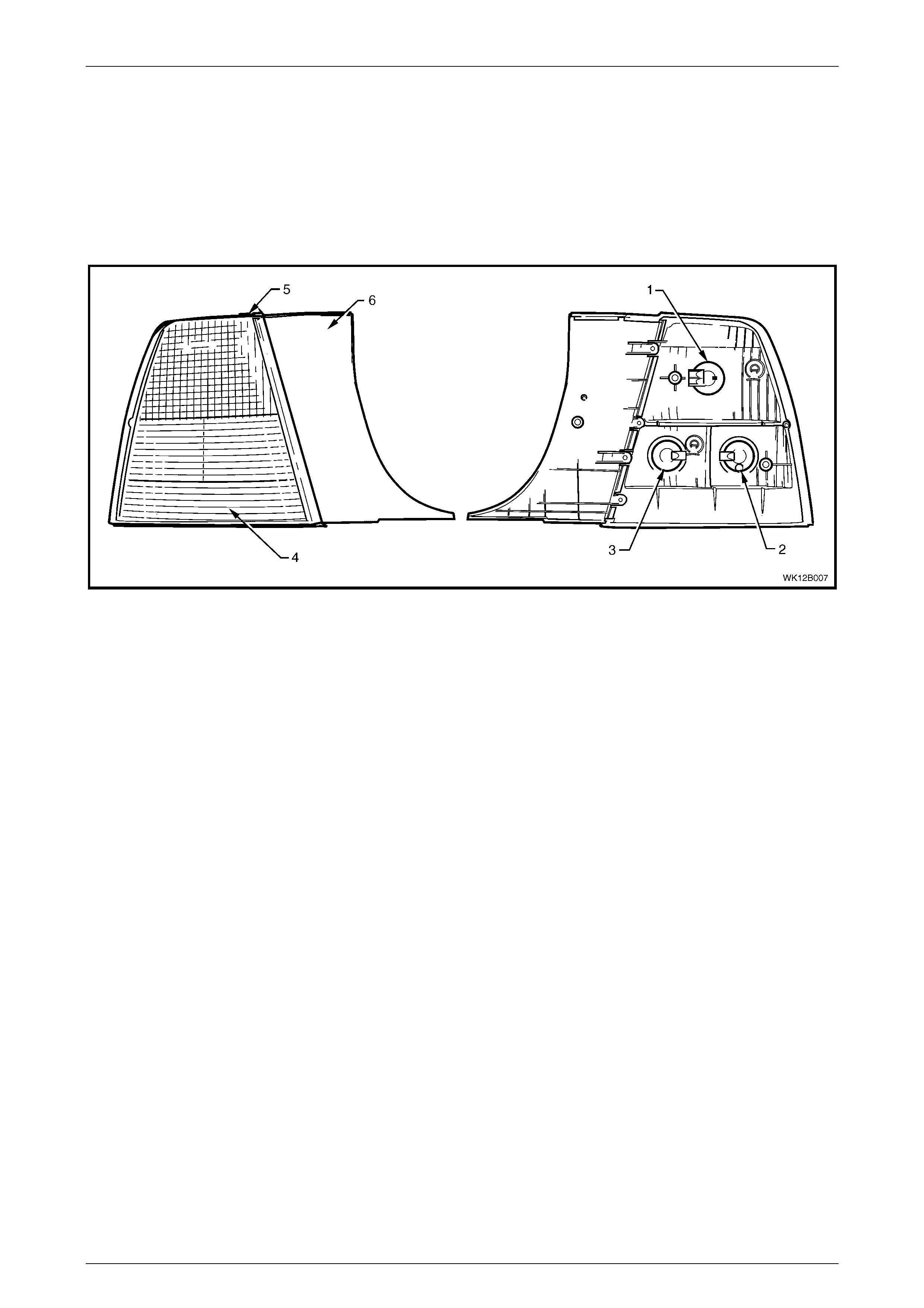
1.4 Tail Lamp Assembly
The tail lamps fitted to all WK Series vehicles are designed to be functional and provide aesthetically pleasing looks to
compliment WK Series vehicle body styling. A single tail lamp configuration is maintained across all WK Series vehicle
levels. The tail lamp lens has been designed to provide a distinctive all red appearance. Amber turn signal illumination is
provided through the use of an orange tinted glass indicator bulb and clear lens provisions within the tail lamp lens
assembly. Back up lamp illumination operates in a similar fashion however the back up globe is not tinted.
For views of the front and rear of the tail lamp assembly, refer to Figure 12B – 3.
Figure 12B – 3
Legend
1 Stop/Tail Lamp
2 Turn Signal Lamp
3 Back up Lamp
4 Reflex Reflector
5 Dust Seal
6 Rear Quarter Filler Panel

Lighting Syst em Page 12B–8
Page 12B–8
1.5 Hazard Warning Switch
For model Level 1 vehicles, the hazard warning switch is located centrally within the instrument fascia, below the air
outlets. For all other model level vehicles, the hazard warning switch is located within the floor console assembly.
Lighting Syst em Page 12B–9
Page 12B–9
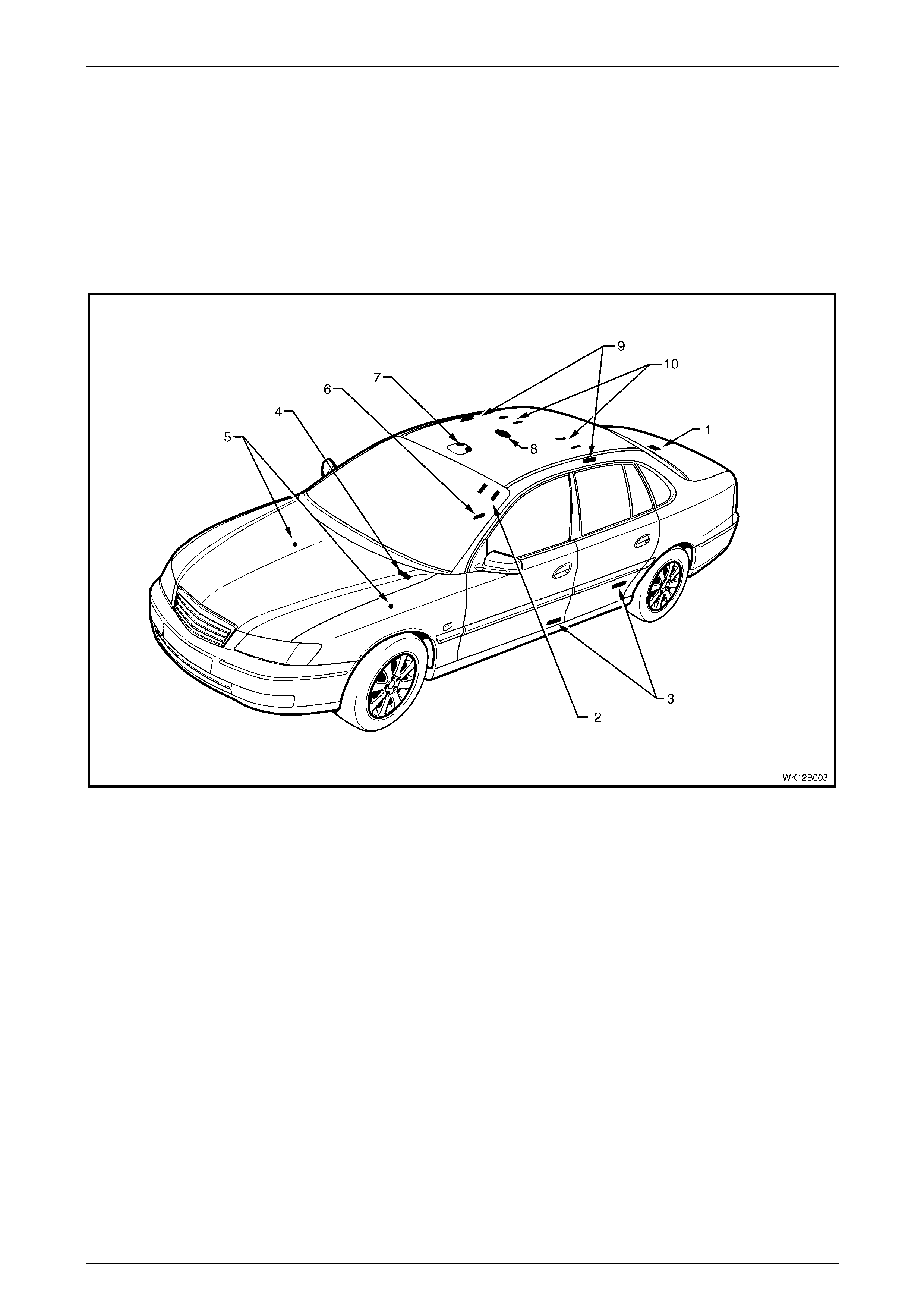
1.6 Interior Illumination
All WK vehicles are fitted with a roof console assembly, except for Level 1 vehicles not fitted with a sunroof. Level 1
vehicles without a sunroof are fitted with a dome and reading lamp assembly. These features provide general interior and
reading illumination. The roof console assembly also incorporates a sunglass holder.
Where fitted, additional interior lighting is provided by courtesy lamps in the side door trims, front stepwell, instrument
panel compartment, floor console compartment, vanity mirrors and the rear compartment. Roof rail courtesy and reading
lamp assemblies are also installed and may be switched on or off independently.
Refer to Figure 12B – 4 for interior lighting component locations.
Figure 12B – 4
Legend
1 Rear Compartment Courtesy Lamp
2 Sunshade Vanity Mirror Lamps
3 Side Door Courtesy Lamps
4 Instrument P anel Compartment Courtesy Lamp
5 Front Stepwell Lamps
6 Floor Console Lamp
7 Roof Console
8 Dome Lamp
9 Roof Rail Court esy and Reading Lam ps
10 Rear Vanity Mirror Lamps
Lighting Syst em Page 12B–10
Page 12B–10
1.7 Instrument and Switch Illumination
All instrument and switch illumination is provided by Light Emitting Diodes (LEDs) with the exception of the following,
which are illuminated with bulbs:
• Hazard warning switch
• Left-hand drive fuel filler door lock release switch
• Traction contr ol switch
• Power control switch
• Headlamp switch assembly
• Ignition lock cy lind er
• Trip computer switch
• LPG (Liquified Petroleum Gas) switch
• Rear remote control
The headlamp and trip computer are sealed units and the conventional bulbs cannot be serviced on these items.
LED’s are used instead of conventional bulbs due to their longevity in operation. If the illumination of any LED equipped
item no longer operates correctly, and the LED is isolated as the fault, replace the assembly in question.
Figure 12B – 5
Legend
1 Auxiliary Switches
2 Fuel Tank Filler Door Lock Release Switch, LHD
3 Headlamp Switch
4 Trip Computer Switch
5 Hazard Warning S witch, Level 1
6 Traction Control and Power Switches
7 Hazard Warning S witch, Levels 2 – 5
8 Rear Controller Assembly
Lighting Syst em Page 12B–11
Page 12B–11
2. Service Operations – Exterior
Illumination
2.1 Front Fog Lamp Aiming
During fog lamp aiming procedures, do not
use a cloth or similar material to cover the
lens of the fog lamp assembly not being
adjusted. Damage to the fog lamp assembly
may result if the fog lamp beam is obstructed
in this manner.
The front fog lamp assemblies must be correctly aimed in order to obtain the maximum road illumination and safety. The
fog lamps must be checked for correct aim whenever a bulb or lamp assembly is replaced, and after any adjustments or
repairs to the front-end sheetmetal or bumper fascia.
Headlamp and fog lamp aiming devices are in general use. When using a headlamp and fog lamp aiming device, ensure
that it is in good condition and carefully follow the instructions as set out by the manufacturer.
Regardless of the method used for checking fog lamp aim, the vehicle must be at kerb weight, that is, with full fuel level,
oil, water and spare tyre but no passengers. The tyres must be uniformly inflated to their specified pressure.
If the vehicle will regularly carry an unusual
load in the rear compartment or tow a trailer,
these loads should be on the vehicle when
the fog lamps are checked.
Front Fog Lamp Aim
LT Section – XX-XXX
This procedure is to be used only when suitable test
equipment is not available.
1 Set up a screen or use a vertical wall, in conjunction
with a flat horizontal floor. Park the vehicle
immediately in front of a screen / wall and mark the
following lines on it:
a A vertical centre line (3), which corresponds to
the centre of the vehicle.
b Two vertical lines (2 and 4). These lines are to
correspond to the respective centre of the fog
lamp bulb on each side of the vehicle.
c A horizontal line (1), that corresponds to the
centre of the fog lamp bulb.
2 To check whether the marks are correctly positioned,
turn on the fog lamps.
3 Reverse the vehicle straight back so the that the front
is 5 metres in front of the screen or wall, ensuring that
the centre of the vehicle is aligned with the vehicle
centre line mark (3) on the screen.
Figure 12B – 6
Lighting Syst em Page 12B–12
Page 12B–12
4 Turn the front fog lamps on. Individually aim each fog
lamp to a point symmetrical about the centre line (2),
with the cut-off line (3) 100mm below the fog lamps
horizontal centre line (1).
NOTE
There is no provision for horizontal adjustment.
Fog lamps are fixed to a vertical centre line.
Figure 12B – 7
5 Fog lamp aim adjustment is made by rotating the
adjuster knob (1) on the back of the lamp housing.
Turning the adjuster anti-clockwise lowers the beam.
Turning the adjuster clockwise raises the beam.
Figure 12B – 8
Lighting Syst em Page 12B–13
Page 12B–13
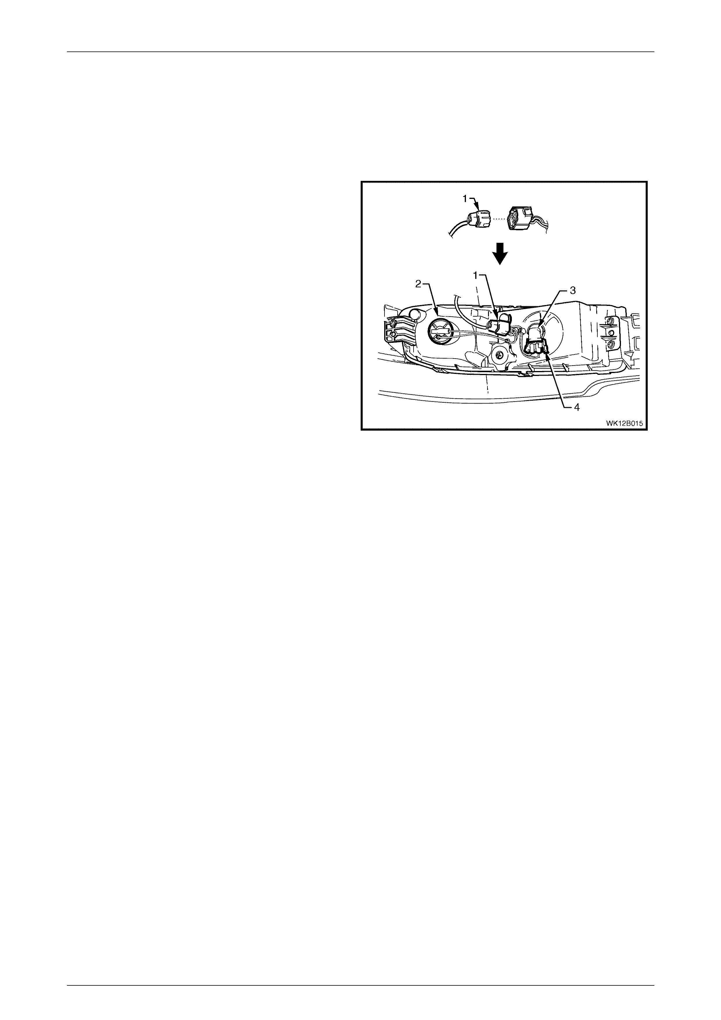
2.2 Front Fog Lamp Bulb
LT Section – 02-325
Replace
1 Remove the fusible link F102. Refer to MY 2003 VY
and V2 Series Service Information, Section 12B,
3.27 Engine Compartment Fuse and Panel Assembly.
2 Rotate the fog lamp bulb and wiring connector
assembly (1) anti-clockwise and remove from the fog
and turning lamp assembly (2).
3 Disconnect the wiring connector from the bulb by
squeezing the two tangs together and pulling the
connector down from the bulb.
4 Inspect the condition of the O-ring seal (3). Replace
the seal if damaged or deformed.
NOTE
Do not handle the quartz envelope of the bulb
assembly. If the envelope is touched
accidentally, wipe it immediately with
methylated spirits or the bulb’s performance will
be deteriorated.
Figure 12B – 9
5 Install a new bulb into the bulb connector by sliding it into the base of the bulb until the tangs engage. Lock the bulb
in place by turning it clockwise.
6 Replace the fusible link F102.
7 Check the fog lamp operation and the aim of the fog lamp as the bulb filament with respect to the reflector may
have changed. Refer to 2.1 Front Foglamp Aiming in this Section.
Lighting Syst em Page 12B–14
Page 12B–14
2.3 Front Cornering Lamp Bulb
LT Section – XX-XXX
Replace
1 Remove the fusible link F102. Refer to MY 2003 VY
and V2 Series Service Information, Section 12B, 3.27
Engine Compartment Fuse and Relay Panel
Assembly.
2 From behind the front bumper fascia, twist to release
the bulb socket (1) from the lamp assembly (4) and
remove the bulb socket from the lamp assembly.
3 Press the bulb (3) into the socket and rotate
anti-clockwise to remove.
4 Inspect the O-ring seal (2) on the bulb socket for
damage and correct seating. Replace the seal if
necessary.
5 Insert a new bulb into the socket. Install the bulb
socket into the lamp assembly and twist to lock.
6 Replace the fusible link F102.
7 Check the cornering lamp operation.
Figure 12B – 10
Lighting Syst em Page 12B–15
Page 12B–15
2.4 Fog and Cornering Lamp Harness
LT Section – XX-XXX
Remove
1 Remove the fusible link F102. Refer to MY 2003 VY
and V2 Series Service Information, Section 12B, 3.27
Engine Compartment Fuse and Relay Panel
Assembly.
2 From behind the front bumper fascia, disconnect the
main wiring harness (1) from the fog and cornering
lamp a s sembly har nes s connecto r by pressing the top
tang and pulling the connectors apart.
3 Twist the cornering lamp socket (2) anti-clockwise
and pull to remove the socket from the fog and
turning lamp assembly.
4 Disconnect the wiring connector (4) from the fog lamp
bulb (3) by squeezing the two side tangs together and
pulling the connector down from the bulb.
5 Unclip the harness connector and wires from the fog
and turning lamp assembly.
Figure 12B – 11
Reinstall
Installation of the fog and cornering lamp harness is the reverse of the removal procedure, noting the following:
1 Check the operation of the cornering lamp and fog lamps upon reinstallation.
Lighting Syst em Page 12B–16
Page 12B–16
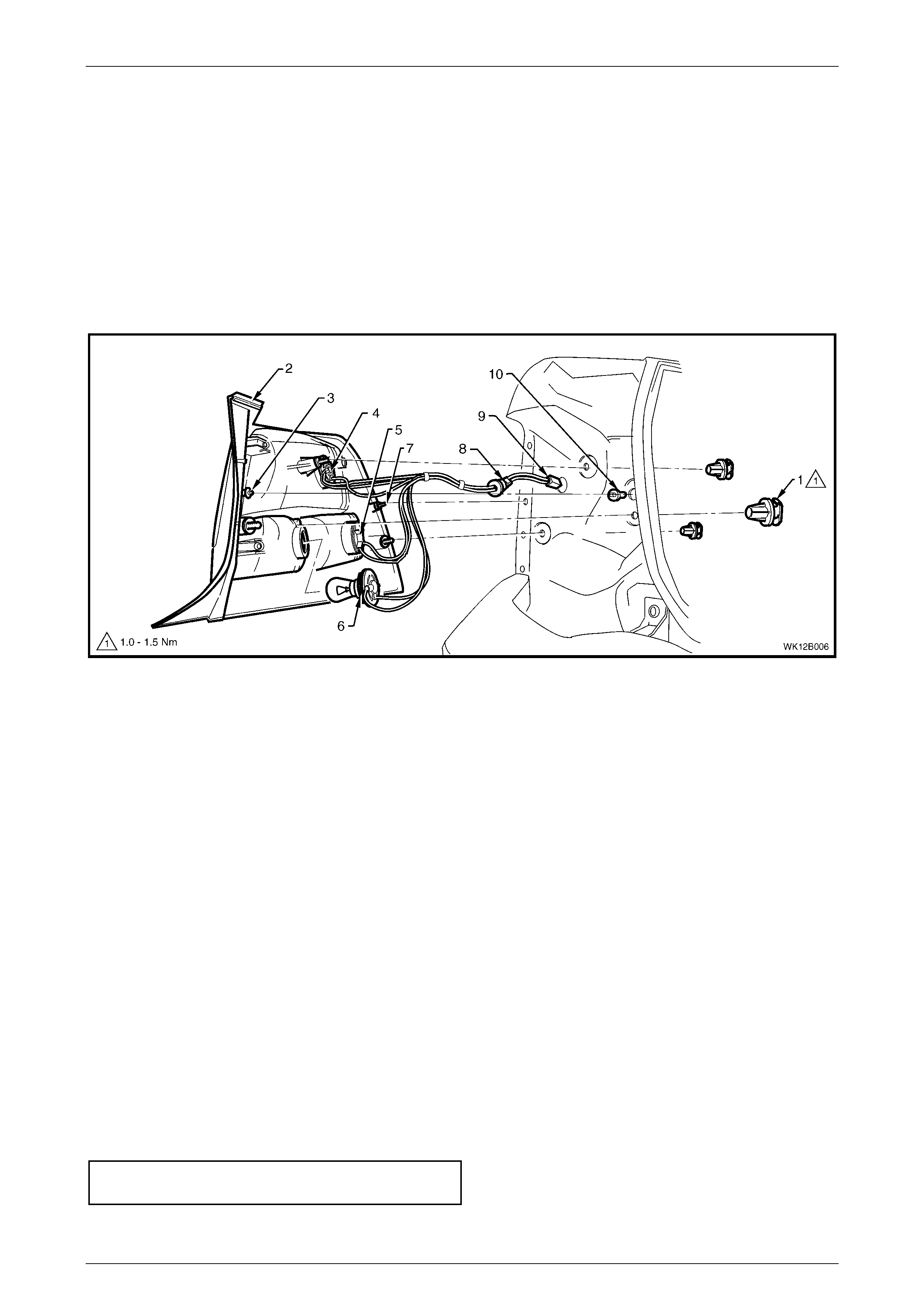
2.5 Tail Lamp Assembly Bulbs
LT Section – 02-350
Replace
1 Remove the fusible link F102. Refer to MY 2003 VY and V2 Series Service Information, Section 12B, 3.27 Engine
Compartment Fuse and Relay Panel Assembly.
2 Open the rear compartment lid.
3 Remove the tail lamp attaching nuts (1), refer to Figure 12B – 12, item 1.
Figure 12B – 12
Legend
1 Attachi ng Nut (3 places)
2 Tail Lamp Assembly
3 Pivot Pin
4 Stop/Tail Lamp Socket
5 Turn Signal Lamp Socket
6 Back up Lamp Socket
7 Locator Pin and Weather Seal Washer
8 Rubber Grommet
9 Harness Connector
10 Pivot Pin Locat i ng Nutsert
4 From the exterior of the vehicle, pull the tail lamp assembly (2) away from the vehicle.
5 Remove the appropriate bulb socket (4, 5 or 6) by turning the socket anti-clockwise and pulling it away from the
lamp assembly.
6 Remove the bulb from the socket by depressing the bulb and then rotating it anti-clockwise.
7 Inspect the bulb socket to lamp assembly seal for damage and replace if necessary.
8 Insert a new bulb into the socket and install the socket into the lamp assembly, ensuring that the socket locks
securely into place.
NOTE
Lamp sockets have differing lug configurations to
prevent installation into the incorrect lamp
receptacle.
9 Install the lamp assembly onto the vehicle.
10 Secure the assembly with the tail lamp attaching nuts and tighten to the correct torque specification.
Tail lamp assembly attaching nut
torque specific atio n .................................... 1.0 – 1.5 Nm
11 Fit the fusible link F102 and check the tail lamp operation.

Lighting Syst em Page 12B–17
Page 12B–17
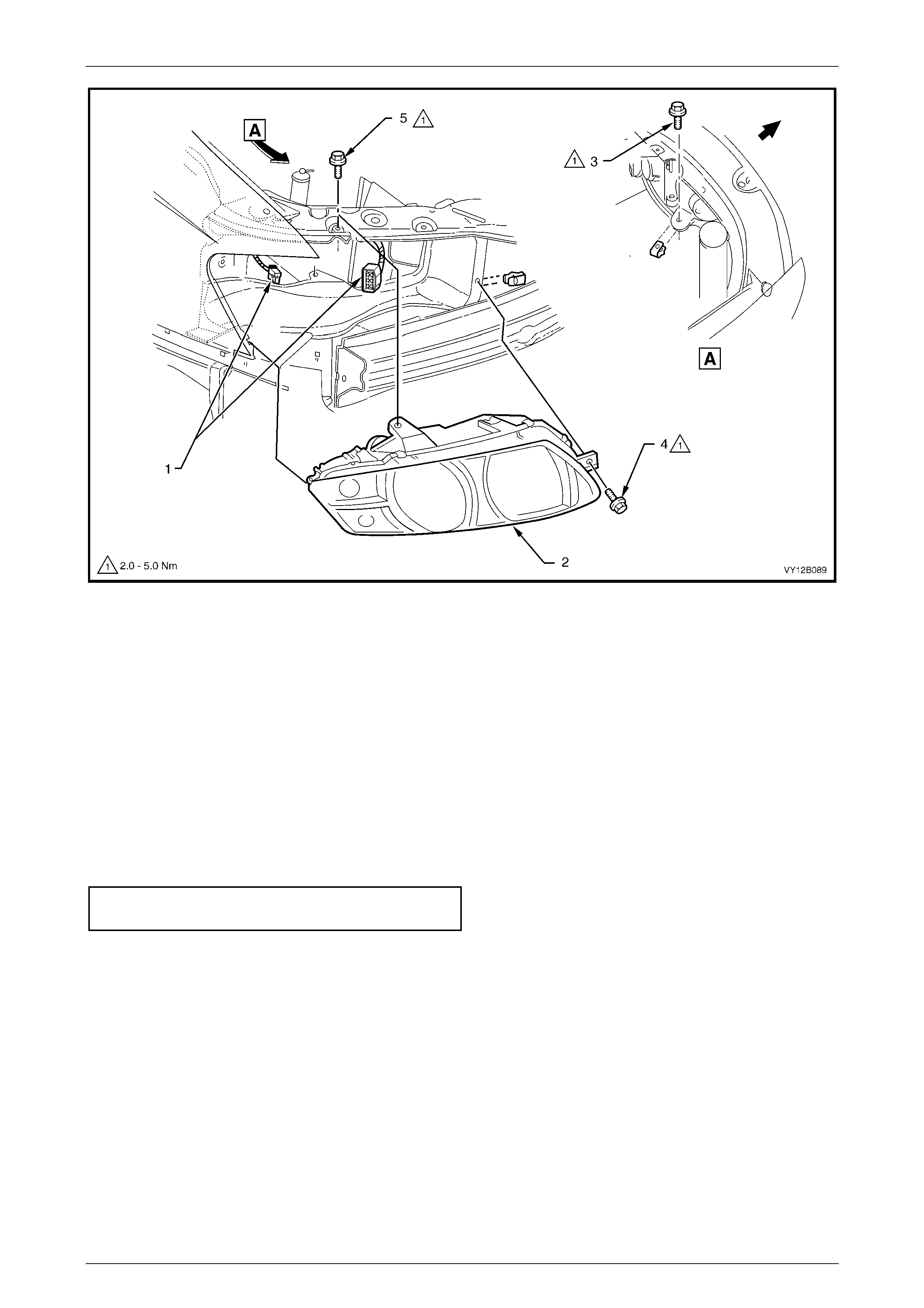
2.6 Headlamp Assembly
LT Section – 02-300
Remove
1 Remove the fusible link F102. Refer to MY 2003 VY and V2 Series Service Information, Section 12B, 3.27 Engine
Compartment Fuse and Relay Panel Assembly.
2 Remove the front bumper fascia assembly. Refer to Section 1D, 2.2 Front Bumper Fascia Assembly.
3 Remove the front fascia support. Refer to Section 1D, 2.4 Front Fascia Support.
4 For GEN III V8 engine models, remove the four retainers securing the upper radiator shroud and remove the
shroud. Refer to MY 2003 VY and V2 Series Service Information, S ection 6B3, 2.16 Radiat or.
5 For the right-hand headlamp assembly, it may be necessary to remove the battery to gain the required access.
a If required, remove the battery hold-down bracket and move the battery to gain access. Refer to MY 2003 VY
and V2 Series Service Information, Section 12A, 2.9 Battery .
b If further access is required, remove the battery terminals from the battery and remove the battery from the
engine compartment. Refer to MY 2003 VY and V2 Series Service Information, Section 12A, 2.9 Battery.
Disconnection of the battery affects certain
vehicle electronic systems. Refer to
Section 00, 6 Battery Disconnection
Procedures before disconnecting the battery.
6 For left-hand headlamp assemblies on V6 engine models, remove the coolant filler bottle neck and place to one
side.
7 Disconnect the turn signal and headlamp wiring harness connectors (1) from the rear of the headlamp
assembly (2), refer to Figure 12B – 13.
8 Remove the three headlamp retaining screws (3, 4 and 5) and remove the headlamp assembly.
Lighting Syst em Page 12B–18
Page 12B–18
Figure 12B – 13
Legend
1 Harness Connectors
2 Headlamp Assembly 3 Headlamp Retaining Screws
4 Front Fascia Support
Reinstall
Installation of the headlamp assembly is the reverse of the removal procedure, noting the following points:
1 Connect all the wiring harness connectors and check the operation of the headlamps and turn signal/parking
lamps.
2 Install the headlamp assembly and tighten the retaining screws to the correct torque specification.
Headlamp as sem bly retaini ng
screw torque specification..........................2.0 – 5.0 Nm
Lighting Syst em Page 12B–19
Page 12B–19
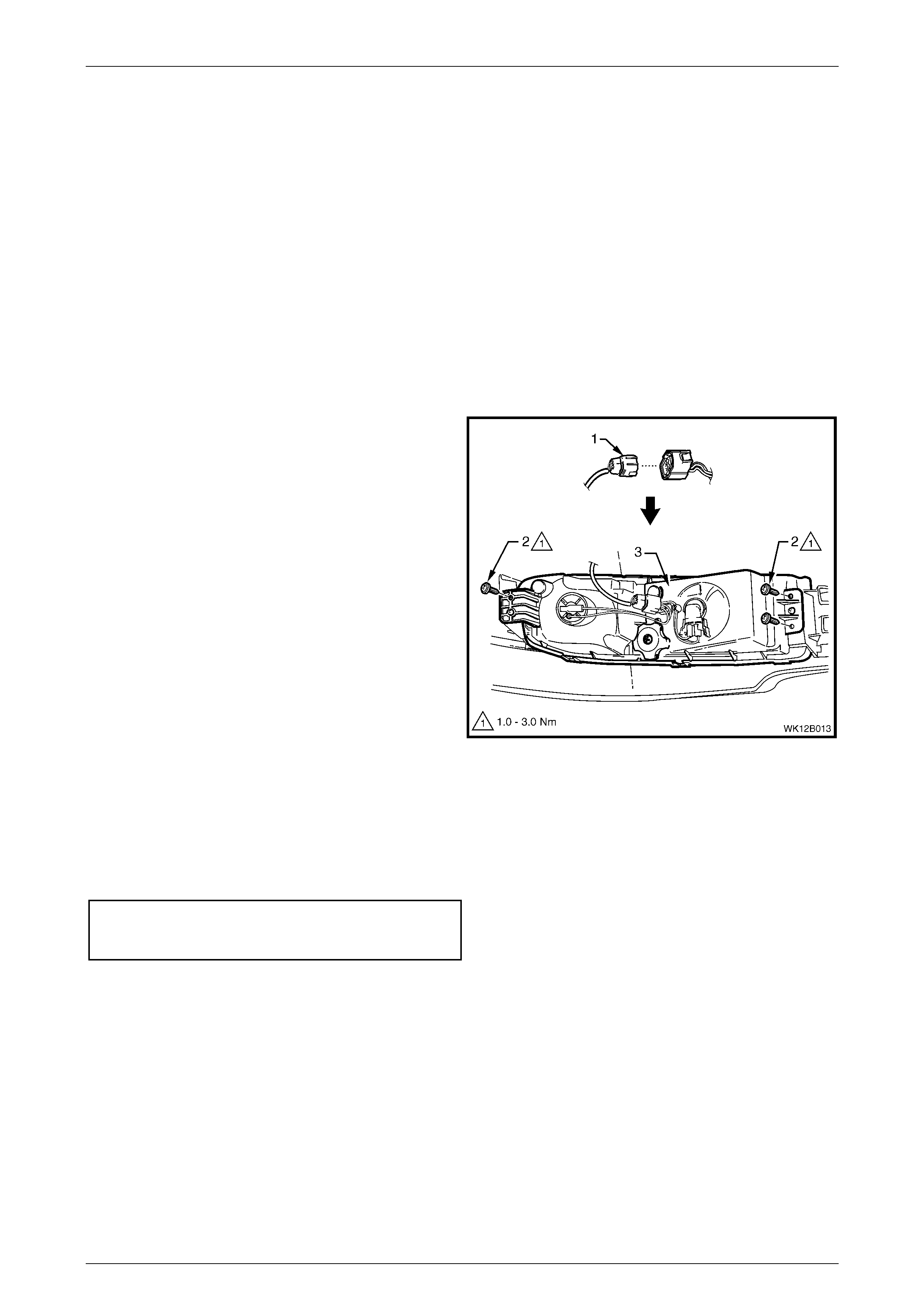
2.7 Fog and Cornering Lamp Assembly
LT Section – 02-325
For the removal and installation of the front fog and cornering lamp assembly fitted wi th a metal strip bracket attached to
the front bumper fascia, refer to Section 1D, 2.2 Front Bumper Fascia Assembly.
NOTE
The two attachment lugs and two support lugs for
the front fog and cornering lamp assemblies may
be present on the front bumper fascia as the
rigidity improvement of the interface with the front
bumper fascia was a running change.
Remove
1 From behind the front bumper fascia, disconnect the
main wiring harness (1) from the fog and cornering
lamp assembly harness connector by squeezing the
top tang together and pulling each of the connectors
apart.
2 Remove the three screws (2) securing the fog and
cornering lamp assembly (3).
3 Carefully pull the outboard end of the assembly away
from the bumper fascia mounting pin.
4 Slide the inboard end of the assembly out from behind
the lower grille mounting lug and away from the
mounting pin.
Figure 12B – 14
Reinstall
Installation of the fog and cornering lamp assembly is the reverse of the removal procedure, noting the following points:
1 Tighten the three screws (2) attaching the fog and cornering lamp assembly to the front bumper fascia, to the
correct torque specification, refer to Figure 12B – 14.
Fog and cornering lamp assembly
to front bumper fascia attaching screw
torque specific atio n .................................... 1.0 – 3.0 Nm
NOTE
If a new fog and cornering lamp assembly with a
metal strip bracket is to be fitted to a front bumper
fascia which does not have the two attaching
lugs for the bracket, remove the bracket before
installing the lamp assembly, refer to
Section 1D, 2.2 Front Bumper Fascia Assembly.
Add sponge foam between the lamp and bumper
interface for rigidity.
Lighting Syst em Page 12B–20
Page 12B–20
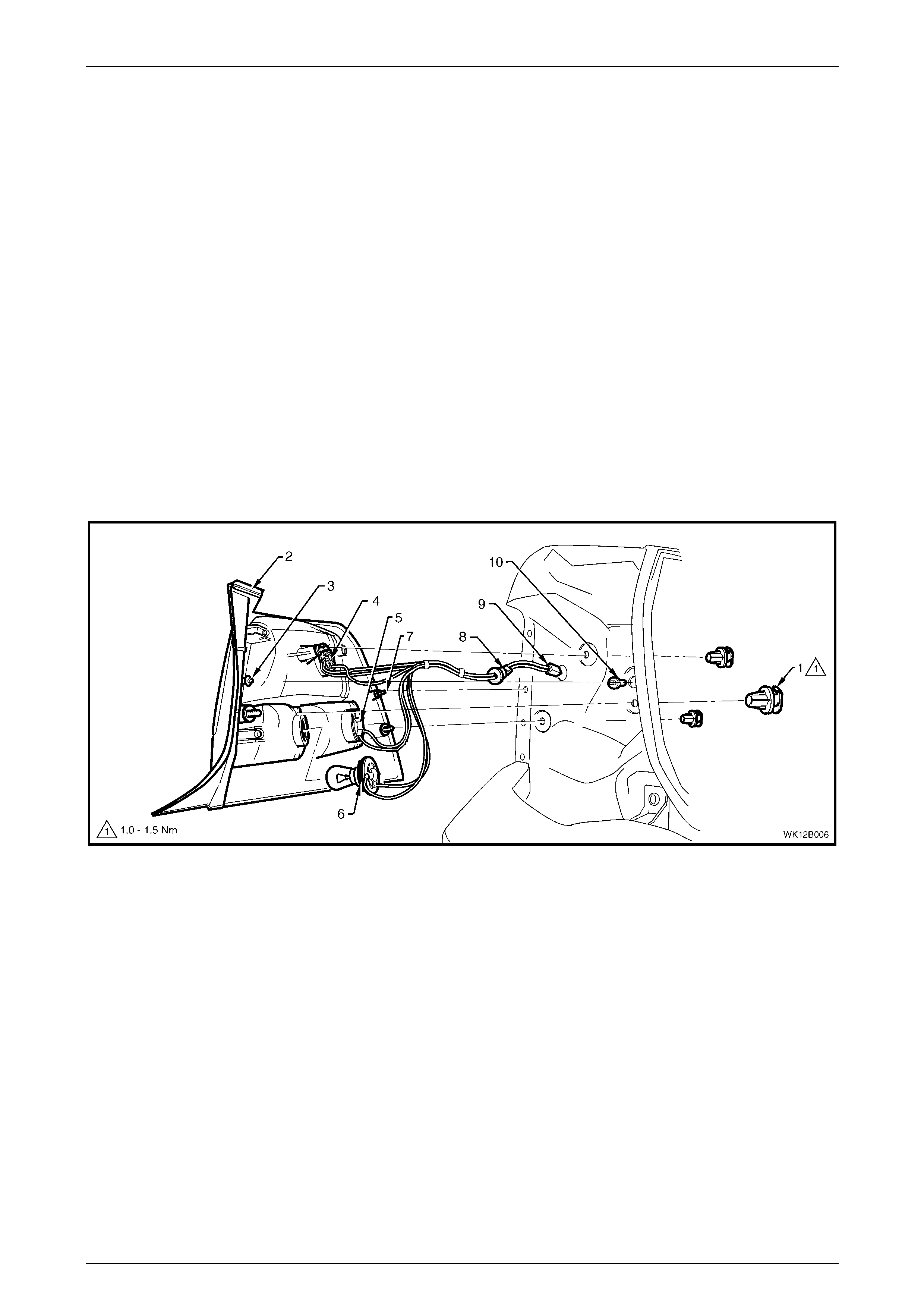
2.8 Tail Lamp Assembly
Remove
1 Remove the fusible link F102. Refer to MY 2003 VY and V2 Series Service Information, Section 12B, 3.27 Engine
Compartment Fuse and Relay Panel Assembly.
2 Open the rear compartment lid.
3 Remove the convenience net, refer to Section 1A8, 2.19 Convenience Net in the MY 2003 VY and V2 Series
Service Information.
4 Remove the quarter inner rear side carpet, refer to Section 1A8, 2.7 Quarter Inner Rear Side Carpet.
5 Unscrew each of the three tail lamp attaching nuts, refer to Figure 12B – 15.
6 From the exterior of the vehicle, pull the tail lamp assembly away from the vehicle and support the assembly.
7 Remove all the bulb sockets (4, 5 and 6) by turning the sockets anti-clockwise and pulling them away from the
reflector.
8 If removing the wiring harness:
a Disconnect the tail lamp wiring harness connector (9) from the body wiring harness.
b Pull the rubber grommet (8) out from the sheetmetal and remove the harness.
Figure 12B – 15
Legend
1 Attachi ng Nut (3 places)
2 Tail Lamp Assembly
3 Pivot Pin
4 Stop/Tail Lamp Socket
5 Turn Signal Lamp Socket
6 Back up Lamp Socket
7 Locator Pin and Weather Seal Washer
8 Rubber Grommet
9 Harness Connector
10 Pivot Pin Locat i ng Nutsert

Lighting Syst em Page 12B–21
Page 12B–21
Reinstall
Installation of the tail lamp assembly is the reverse of the removal procedure, noting the following points:
1 Inspect the socket to lamp assembly seals for damage and replace where required.
2 If required, replace the tail lamp wiring harness.
3 Ensure that the lamp sockets are installed into the lamp assembly correctly.
NOTE
Lamp sockets have differing lug configurations to
prevent installation into the incorrect tail lamp
assembly receptacle.
4 Ensure that the weather seal washer is fitted to the outboard tail lamp locator pin (7), refer to Figure 12B – 15.
5 Check that the pivot pin locating nutsert (10) is securely located in place.
6 Tighten the tail lamp assembly retaining nuts (1) to the correct torque specification.
Tail lamp assembly attaching nut
torque specific atio n .................................... 1.0 – 1.5 Nm
Lighting Syst em Page 12B–22
Page 12B–22
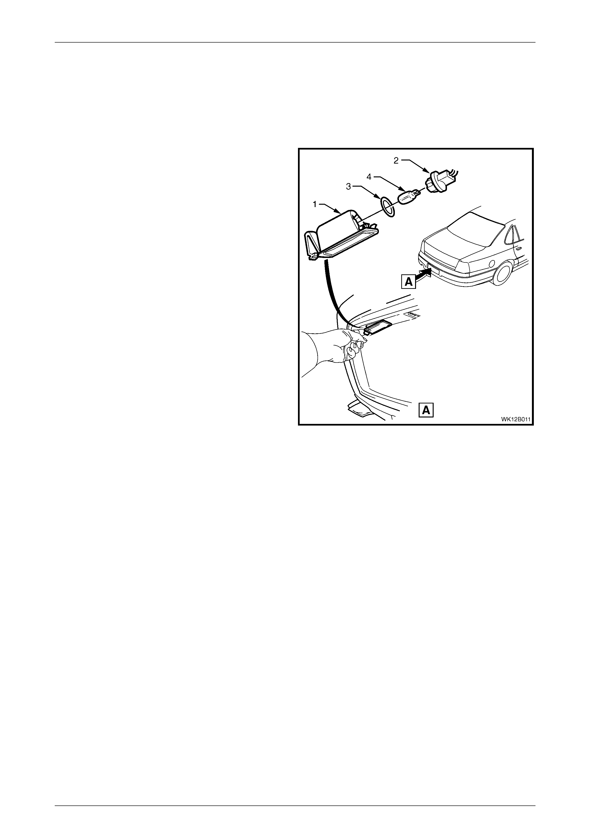
2.9 Rear License Plate Lamp Assembly
LT Section – 02-385
Remove
1 Remove the fusible link F102. Refer to MY 2003 VY
and V2 Series Service Information, Section 12B,
3.27 Engine Compartment Fuse and Relay Panel
Assembly.
2 Push the locking tang located at the end of the lamp
housing (1) towards the len s. Pivot the housin g dow n
and remove it from the aperture.
3 Remove the bulb socket (2) from the lamp housing.
4 If required, replace the bulb (3) by pulling it from the
socket.
5 Inspect the bulb socket seal (4) for damage and
replace if re quired.
Figure 12B – 16
Reinstall
Installation of the rear licence plate assembly is the reverse of the removal procedure noting the following points:
1 Insert a new bulb into the assembly if required.
NOTE
The lamp housing will install into the aperture in
one direction only.
2 Check the rear licence plate lamp operation.

Lighting Syst em Page 12B–24
Page 12B–24
3 Service Operations – Interior
Illumination and Switching
3.1 Hazard Warning Switch As sembly
LT Section – 02-800
Level 1
For hazard warning switch replacement on Level 1 WK vehicles, refer to MY 2003 VY and V2 Series Service Information,
Section 12B, 3.25 Hazard Warning Switch Assembly.
Level 2 to 5
Remove
The hazard warning switch is located in the front floor console.
1 Ensure that the ignition switch is in the OFF position.
2 Remove the fusible link F102. Refer to MY 2003 VY and V2 Series Service Information, Section 12B, 3.27 Engine
Compartment Fuse and Relay Panel Assembly.
3 If required, remove the following navigation system equipment:
a Navigation remote control cradle, refer to Section 12L Navigation System.
b Navigation monitor escutcheon, refer to Section 12L Navigation System.
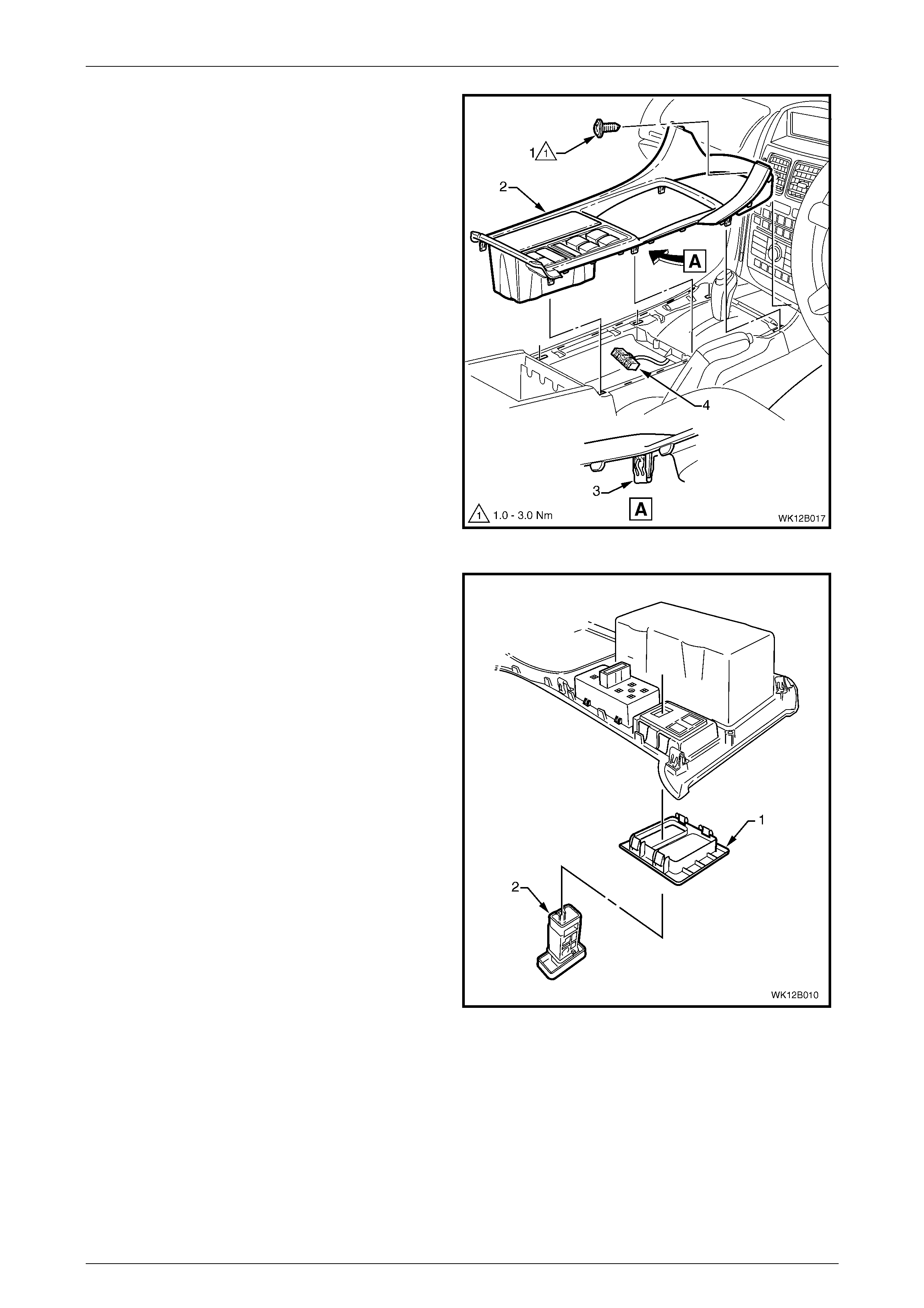
4 Remove the floor console front compartment liner (1)
by lifting it upwards to disengage the retaining lugs.
Figure 12B – 17
Lighting Syst em Page 12B–25
Page 12B–25
5 Remove the screw (1) attaching the floor console
cover assembly (2).
NOTE
Vehicles fitted with navigation system do not
have this screw.
6 Prise the cover from the front floor console in six
places (3).
7 Lift the cover assembly up from the rear and
disconnect the wiring connector (4) from the side
window switch assembly, and the wiring connectors
from the hazard warning switch and LPG switch
where fitted.
8 Remove the cover assembly.
Figure 12B – 18
9 From the underside of the console cover assembly
press the four tabs securing the auxiliary switch bezel
assembly (1). Remove the bezel assembly.
10 As required, press the two tabs securing the hazard
warning switch assembly (2) to the console cover
assembly and remove the switch.
NOTE
Record the orientation and position of the switch
assembly being removed.
Figure 12B – 19
Reinstall
1 Connect the hazard warning switch to the correct wiring connector in the floor console. Install the fusible link F102.
Turn on the park lamps and check for the correct operation of the bulb.
2 Remove the fusible link F102. Disconnect the wiring connector from the switch assembly.
3 Insert the switch assembly into the console cover assembly ensuring the position and orientation are correct.
4 Insert the bezel into the cover assembly and ensure that it locks into place securely.
5 Lift the cover assembly onto the front floor console inserting the front of the cover first.
Lighting Syst em Page 12B–26
Page 12B–26
6 Connect all the wiring connectors to the switch assemblies ensuring that each switch is mated to the correct
connector.
7 Press the cover onto the console.
8 Where fitted, insert the screw attaching the floor console cover assembly and tighten to the correct torque
specification.
Floor console cover assembly
att aching screw
torque specific atio n .................................... 1.0 – 3.0 Nm
9 If required, install the following navigation system equipment:
a Navigation monitor escutcheon, refer to Section 12L Navigation System.
b Navigation remote control cradle, refer to Section 12L Navigation System.
10 Install the fusible link F102.
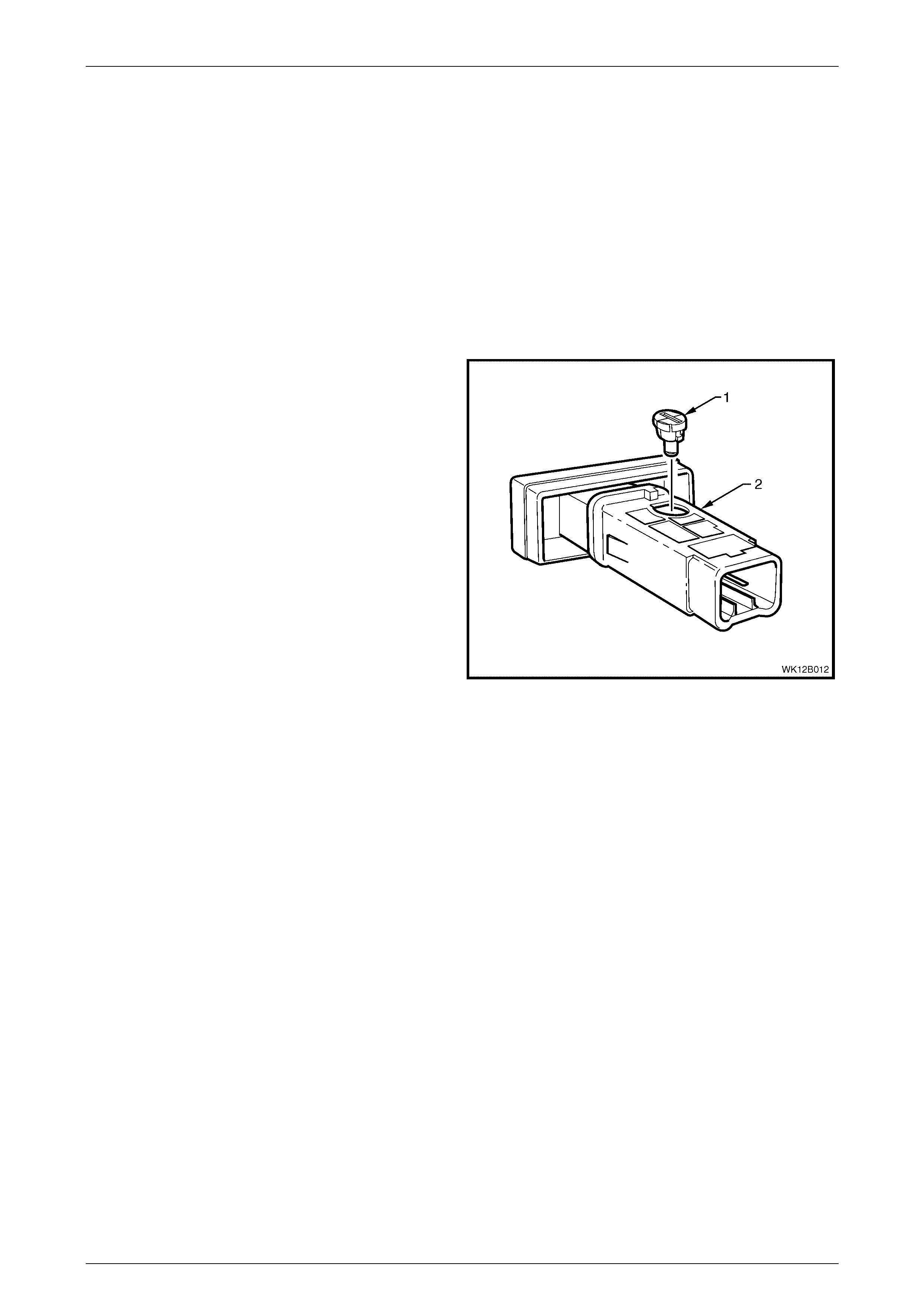
Test
To test the hazard warning switch assembly, an ohmmeter is used to check the continuity or resistance when the
functions of the switch are actuated.
NOTE
Ref er to F igur e 12B – 2 0 in c onjunc tion with the
chart in this Section for the switch positions.
1 Perform the removal procedure for the hazard
warning switch assembly as detailed in this Section.
2 Place the switch in the positions as detailed in the
chart following. Position the contacts of the ohmmeter
onto the terminals and take the reading. Compare the
reading with the chart.
3 If there is continuity between any other terminals
other than those listed, the switch assembly is faulty.
If the switch fails any part of the test, replace the
switch assembly with a serviceable item.
4 Perform the reinstall procedure in this Section.
Figure 12B – 20
HAZARD WARNING SWITCH ASSEMBLY
SWITCH POSITION SWITCH TERM INALS INDICATION IF SWITCH IS
SERVICEABLE
Switch in the OFF position; position A 3 and 4 Continuity
Switch in the ON position; posit i on B 3 and 5 Continuity
Switch in either position, ON or OFF 2 and 6 Approximatel y 30 Ω
Lighting Syst em Page 12B–27
Page 12B–27
3.2 Hazard Warning Switch Bulb
LT Section – 02-800
Level 1
For hazard warning switch replacement on Level 1 vehicles, refer to MY 2003 VY and V2 Series Service Information,
Section 12B, 3.19 Switch Illumination.
Level 2 to 5
Replace
1 Remove the hazard warning switch assembly, refer to
3.1 Hazard Warning Switch Assembly in this Section.
2 Using a fine blade screwdriver inserted into the groove
on the bulb socket, twist the socket and bulb
assembly (1) anti-clockwise and remove from the
switch assembly (2).
3 Replace socket and bulb assembly with a serviceable
item.
4 Insert the socket and bulb assembly into the switch
assembly.
5 Reinstall the hazard warning switch assembly.
Figure 12B – 21
Lighting Syst em Page 12B–28
Page 12B–28
3.3 Rear Vanity Mirror Lamp Bulbs
Replace
1 Press the vanity mirror button and allow vanity mirror
to swing down.
2 Using a fine blade screwdriver (1), carefully lever the
notched ends of the mirror lamp lens (3) from the
vanity mirror (2).
Figure 12B – 22
3 Remove the two screws (1).
4 Using a fine blade screwdriver, lever up the retainers
(2) and (3). Remove the mirror assembly from the
housing asse mbly .
NOTE
Take care not to lose the lamp switch slider (2)
when the vanity mirror is separated refer to
Figure 12B – 26.
Figure 12B – 23
Lighting Syst em Page 12B–29
Page 12B–29
5 Replace the bulbs (1) in the housing assembly as
required.
Figure 12B – 24
6 Install the lamp switch slider (2) into the mirror
assembly (1) and ensure that it is located correctly in
the slot on the side of the housing.
7 Engage the mirror assembly onto the top edge
retainer of the housing assembly (3). Squeeze
together the lower corners of the vanity mirror to
engage the retainers in each bottom corner.
8 Secure the vanity mirror with the two fastening screws
and tighten to the correct torque specification.
Rear vanity mirror housing attaching
screw torque specification..........................2.0 – 3.0 Nm
9 Install the mirror lamp lens into the mirror housing
with the notched ends facing upward.
10 Switch the mirror lamp on and ensure that the bulbs
illuminate.
Figure 12B – 25
Lighting Syst em Page 12B–30
Page 12B–30
3.4 Re ar Remote Control Bulbs
Replace
1 Remove the rear remote control. Refer to Section 1A8, 2.6 Headlining Assembly.
2 Remove four screws (1).
3 Remove the cover (2) from the rear controller
assembly (3).
4 Use a flat-bladed screwdriver to rotate the bulbs (4)
approximately one quarter of a turn in an anti-
clockw ise dir e ctio n.
5 Remove the bulbs from the printed circuit board (5).
6 Insert the new bulbs and ensure they are locked into
place.
7 Install the cover and tighten to the correct torque
specification.
Rear remote con trol cov er scr ew
attaching torque specification..............................0.3 Nm
8 Install the rear remote control. Refer to S ection 1A8,
2.6 Headlining Assembly.
Figure 12B – 26

Lighting Syst em Page 12B–31
Page 12B–31
4 Specifications
BULB POWER RATING
— WATTS TYPE
Hi/lo beam (outboard)
High beam (inboard) 60/55
55 H11
H9
Parking lamps (front) 5 Wedge
Turn signal lamps (front) 21 Offset Pin (Orange glass)
Turn signal lamps (rear) 21 Offset Pin (Orange glass)
Side repeater lamps 5 Wedge
Front fog lamps 27 H27W / 2
Front cornering lamps 21 P21W
Stop and tail lamps 21/ 5 Std. Parall el Pin
Back up lamps 21 Std. Parallel Pin
Licence plate lamps 5 Wedge
Hazard warning lam p switch bulb 1 Twist to lock assembly
LHD fuel filler door lock release
switch bulb 1 Twist to lock assembly
Power switch bulb 1 Twist to lock assembly
Traction control switch bulb 1 Twist to lock assembly
LPG switch bulb 1 Twist to lock assembly
Police lights switch bulb 1 Twist to lock assembly
Rear compartment lamp 10 Festoon
Dome (courtesy) lam p 10 Festoon
Front seat reading lamp 5 Std. Parallel Pin
Roof console lamps 10 Bayonet
Rear seat reading lamp 5 Festoon
Instrument panel com partment
lamp 5 Festoon
Ignition lock bulb 1.4 Wedge
Front stepwell lamps 2.7 Wedge
Front vanity mirror lam p 1.4 Wedge
Rear vanity mirror l am p 1.4 Wedge
Door courtes y lamps 5 Festoon
Floor console compartment lamp 5 Festoon
High mounted stop lamp 18 Wedge
Front and rear cigar lighter bulb 1.2 Wedge
Rear remote control bul b 1.2 Twist to lock assembly

Lighting Syst em Page 12B–32
Page 12B–32
5. Torque Wrench Specifications
Tail lamp assembly attaching nut....................................................1.0 –1.5 Nm
Headlamp assembly retaini ng screw.............................................2.0 – 5.0 Nm
Fog and cornering lamp assembly
to front bumper fascia attaching screw ..........................................1.0 – 3.0 Nm
Rear vanity mirror attaching screw ................................................2.0 – 3.0 Nm
Floor console cover assembly attaching screw..............................1.0 – 3.0 Nm
Rear remote control cover scr ew attaching.............................................0.3 Nm