
Instruments Page 12C–1
Page 12C–1
Section 12C
Instruments
ATTENTION
Before performing any Service Operation or other procedure described in this Section, refer to Section 00
Warnings, Cautions and Notes for correct workshop practices with regard to safety and/or property damage.
1 General Information............................................................................................................................... 2
1.1 General Description...............................................................................................................................................2
1.2 Instrument Fascia Switches..................................................................................................................................6
1.3 Instrument Illumination..........................................................................................................................................7
1.4 Trip Computer – Single Window Cluster..............................................................................................................8
1.5 Trip Computer – Triple Window Cluster...............................................................................................................9
1.6 Instrument Operation – All Models.....................................................................................................................10
Ignition On – Welcome Sequence.......................................................................................................................10
Ignition Off............................................................................................................................................................10
Alarms...................................................................................................................................................................10
1.7 Multi-Function Display – All Models...................................................................................................................11
Constant Icons .....................................................................................................................................................11
Audio ................................................................................................................................................................11
1.8 Customisation Mode............................................................................................................................................12
1.9 Police Mode ..........................................................................................................................................................13
1.10 Holden Special Vehicles......................................................................................................................................14
2 Service Operations.............................................................................................................................. 15
2.1 Instrument Cluster Trim Assembly.....................................................................................................................15
2.2 In-car Air Temperature Sensor............................................................................................................................16
2.3 Instrument Cluster Assembly..............................................................................................................................17
2.4 Instrument Cluster Inputs....................................................................................................................................18
Check ....................................................................................................................................................................18
2.5 Sender Units.........................................................................................................................................................19
Vehicle Speed Sender..........................................................................................................................................19
Fuel Gauge Sender Unit.......................................................................................................................................19
2.6 Trip Computer Switch Assembly........................................................................................................................20
3 Diagnostics........................................................................................................................................... 21
Techline
Techline
Techline
Techline
Techline
Techline
Techline
Instruments Page 12C–2
Page 12C–2
1 General Information
This Section provides a description of the instrument clusters fitted to the MY2004 WK Series vehicles. There are five
levels of vehicle in the WK Series Models. These are:
• Level 1 – Chevrolet Caprice LS,
• Level 2 – Chevrolet Caprice LTZ,
• Level 3 – Chevrolet Caprice SS,
• Level 4 – Holden Statesman, and
• Level 5 – Holden Caprice and Chevrolet Caprice Royale.
1.1 General Description
The instrument cluster fitted to Level 1 and Level 3 vehicles has a single window Multi-function Display (MFD), while the
remaining vehicles have a triple window display, the centre window being the MFD. A trip computer is standard
equipment on all WK Series vehicles. Refer to 1.4 Trip Computer – Single Window Type or 1.5 Trip Computer – Triple
Window Type in this Section for an explanation of trip computer functions.
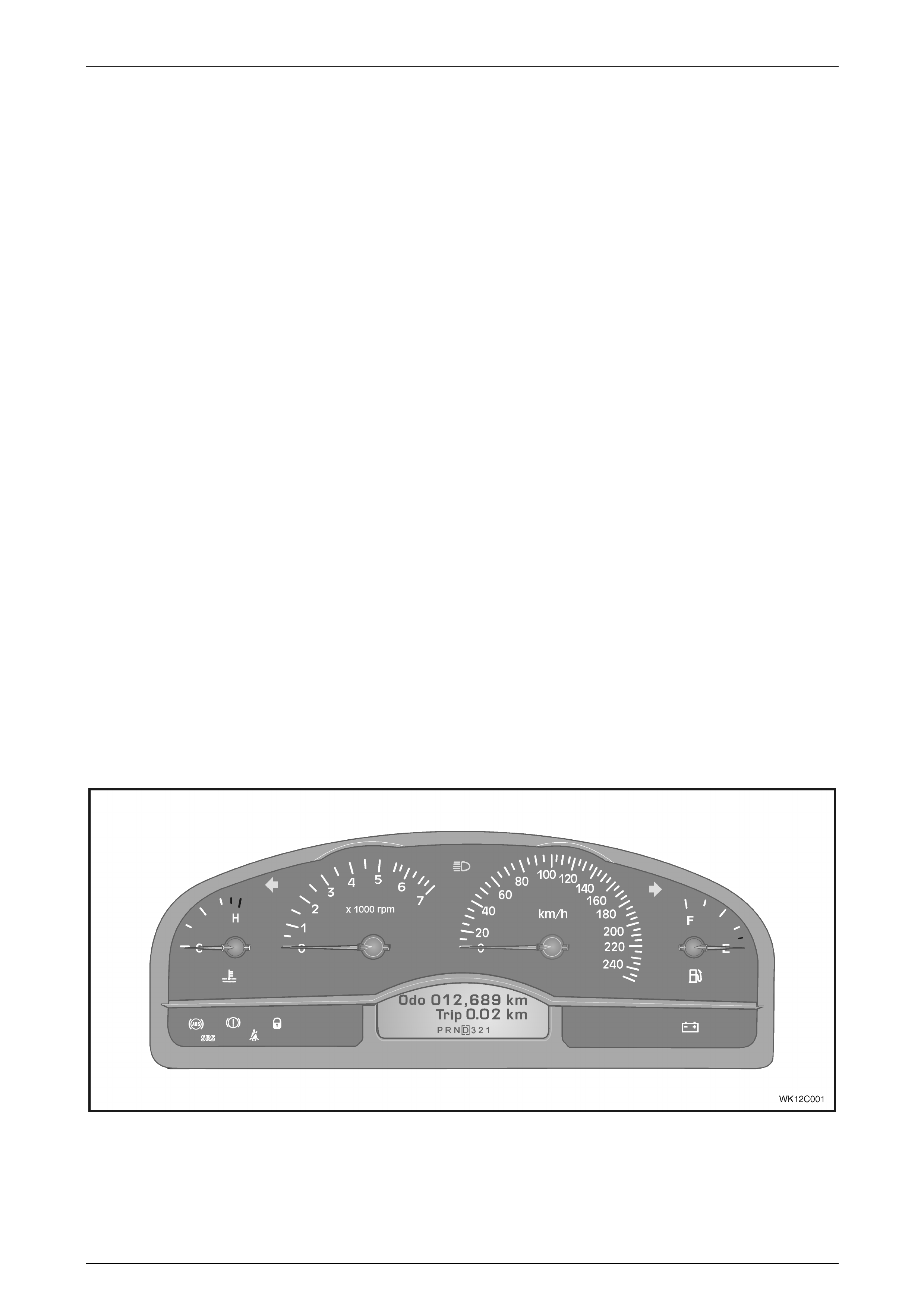
The instrument cluster assembly on WK Series vehicles consists of specific style analogue type instrument gauges. An
electronic speedometer is situated to the right of centre, with the odometer and trip/odometer readings stored on the trip
computer and displayed on the MFD. A tachometer is located to the left of centre, a temperature gauge to the left of the
tachometer and a fuel gauge to the right of the speedometer.
Instrument cluster illumination is by Light Emitting Diodes (LEDs) within the instrument cluster. The LEDs are not
serviceable.
A switch assembly located in the instrument fascia operates the trip computer on both instrument cluster assemblies.
NOTE
If installing a new instrument cluster, the original
odometer reading, together with other important
parameters, must be transferred into the
replacement instrument cluster. This can be done
by an authorised Holden Retailer using TECH 2.
Figure 12C – 1 illustrates the instrument cluster fitted to Level 1 and Level 3 vehicles.
Figure 12C – 1
Instruments Page 12C–3
Page 12C–3
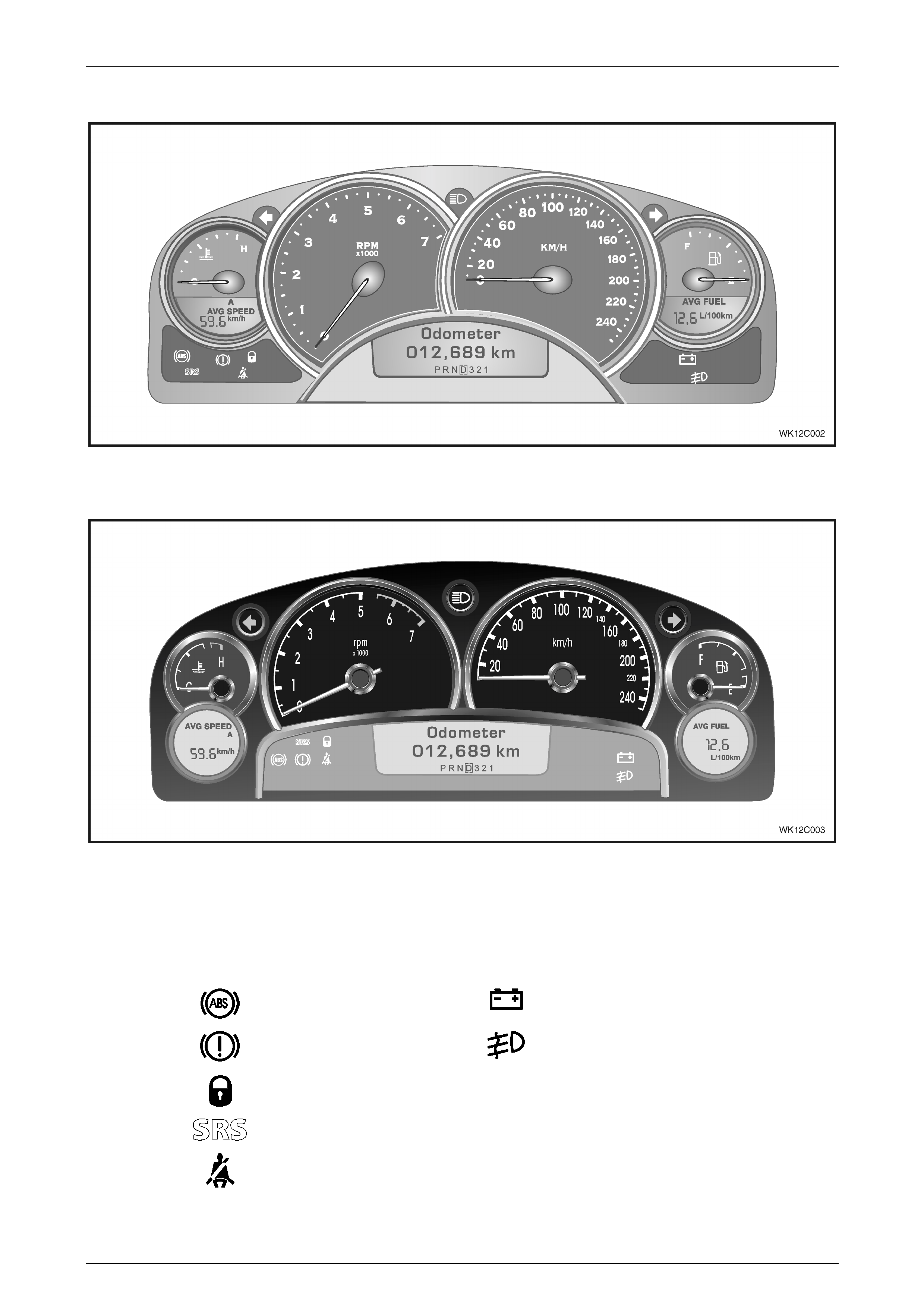
Figure 12C – 2 illustrates the instrument cluster fitted to Level 2 vehicles.
Figure 12C – 2
Figure 12C – 3 illustrates the instrument cluster fitted to Level 4 and Level 5 vehicles.
Figure 12C – 3
The following warning telltales are located beneath the temperature gauge on the left-hand side of the instrument cluster
and beneath the fuel gauge on the right-hand side of the instrument cluster. The telltales are illuminated by LEDs.
LEFT-HAND SIDE RIGHT-HAND SIDE
ABS Off (Amber) Generator Fail (Red)
Brake (Red) – (Park Brake
On or Brake Fail) Front Fog Lamps On (Green)
Security System On (Red)
SRS Fault (Red)
Seat Belt (Red)

Instruments Page 12C–4
Page 12C–4
An audible warning chime is incorporated in the instrument cluster. This feature is used to emphasise the warning
conditions in the following table, with the tone and repetition rate of the chime varied to allow different warnings to be
identified by sound.
In addition to the warning conditions displayed on the MFD, the audible warning chime will sound when buttons on the
trip computer switch assembly are pressed or certain functions are entered.
DESCRIPTION SEQUENCE OF TONES
Overspeed C, F
Underspeed F, C
Low Fuel (petrol or LPG) B1, B
Repeated five times
Fuel Sender Error (petrol or LPG) B1, B
Repeated five times
Park Brake C, D, E, E, E, E, E
Over Temperature C, D, E, E, E, E, E
Low Oil Pressure C, D, E, E, E, E, E
Low Coolant C, D, E, E, E, E, E
Rear Brake Bulb Failure (monitors the rear brake lamps and
the high-mount brake lamp) C, D, E, E, E, E, E
Rear Lamp Bulb Failure (monitors the rear park lamps and
the licence plate lamps) C, D, E, E, E, E, E
Rear Lamp Fuse Failure (monitors the stop lamps fuse and
the park lamps fuse) C, D, E, E, E, E, E
Check Engine C, D, E, E, E, E, E
Check Alternator (Generator) C, D, E, E, E, E, E
SRS Warning D, E, F
Repeated three times
Trip Computer Switch SET button C1, F1
Trip Computer Switch MODE button C
Trip Computer Switch UP or DOWN buttons F
Entering the Auxiliary Function C1, E1
Entering the Customisation Mode C1, E1, F
Using the Reset Function C1, E1, F
Setting a function ON or OFF C1, E1
Shift Up (HSV Only) F
Repeated until warning condition removed
The frequency of each tone is listed in the following table.
TONE FREQUENCY (Hz) TONE FREQUENCY (Hz)
B 494 B1 988
C 523 C1 1047
D 587 — —
E 659 E1 1319
F 698 F1 1397

Instruments Page 12C–5
Page 12C–5
NOTE
Should it be necessary to electric weld on any
vehicle at any time, removal of the instrument
cluster is mandatory. Failure to do so will result in
damage to the instrument gauge circuitry.
If the battery is disconnected for any reason, the following accumulative values are reset:
• Trip Time
• Trip Distance
• Fuel Used
• Average Fuel
• Average Speed
• Stop Watch (if enabled and displaying a non-zero figure).
On all WK Series vehicles the clock is incorporated into the centre console information display.


Instruments Page 12C–8
Page 12C–8
1.4 Trip Computer – Single Window Cluster
WK Series Level 1 and Level 3 vehicles are fitted with a single-window instrument cluster, which is the same as the
single-window instrument cluster fitted to the MY2003 VY Series. Refer to Section 12C, 1.4 Trip Computer – Single
Window Cluster in the MY2003 VY and V2 Series Service Information for details.
Instruments Page 12C–9
Page 12C–9
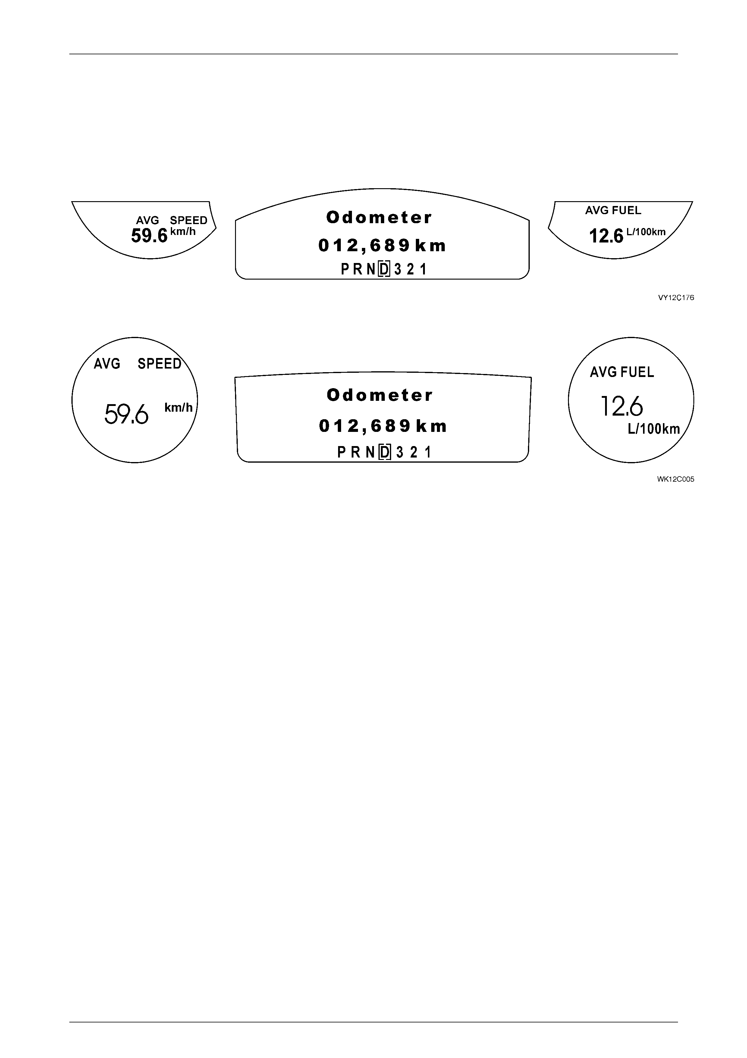
1.5 Trip Computer – Triple Wi ndow Cluster
WK Series Levels 2, 4 and 5 are fitted with a triple-window instrument cluster. The LCDs on the Level 2 instrument
clusters are half-moon shaped, while the LCDs on Levels 4 and 5 are circular as shown in the following figures.
For details on the triple-window instrument cluster, refer to Section 12C, 1.5 Trip Computer – Triple Window Cluster in
the MY2003 VY and V2 Series Service Information.
Figure 12C – 4 Level 2
Figure 12C – 5 Levels 4 and 5
Instruments Page 12C–10
Page 12C–10
1.6 Instrument Operation – All Models
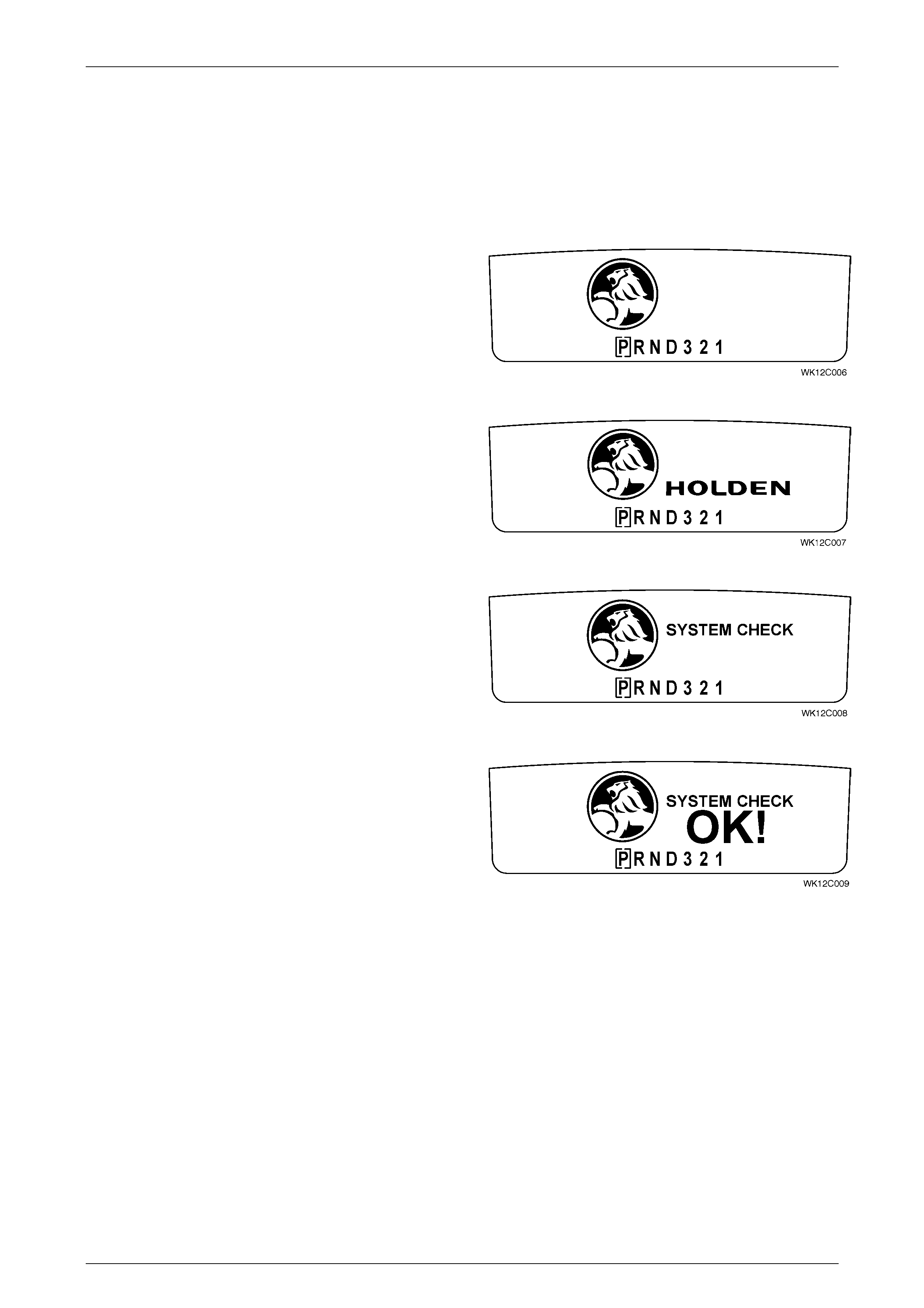
Ignition On – Welcome Sequence
When the ignition switch is turned to the ON position, a vehicle System Check is performed and the status is displayed
on the instrument cluster MFD. The System Check displays the following if there are no warnings or service reminders
active:
Figure 12C – 6
After 0.5 second.
Figure 12C – 7
After 1.0 second.
Figure 12C – 8
After 2.0 seconds.
Figure 12C – 9
NOTE
For Chevrolet vehicles, the Chevrolet ‘Bow Tie’
logo replaces the Holden logo and the wording
‘Holden’ becomes ‘Chevrolet’.
For more details on the Ignition On sequence, refer to the MY2003 VY and V2 Service Information.
Ignition Off
The Ignition Off sequence is the same as for the MY2003 VY Series vehicles. Refer to Section 12C, 1.6 Instrument
Operation – All Models in the MY2003 VY and V2 Service Information.
Alarms
For details on the Alarms, refer to Section 12C, 1.6 Instrument Operation – All Models in the MY2003 VY and V2 Service
Information.
Instruments Page 12C–11
Page 12C–11
1.7 Multi-Function Display – All Models
The operation of the instrument cluster MFD is the same as that for the MY2003 VY Series. Refer to Section 12C,
1.7 Multi-Function Display– All Models in the MY2003 VY and V2 Series Service Information
Constant Icons
Audio
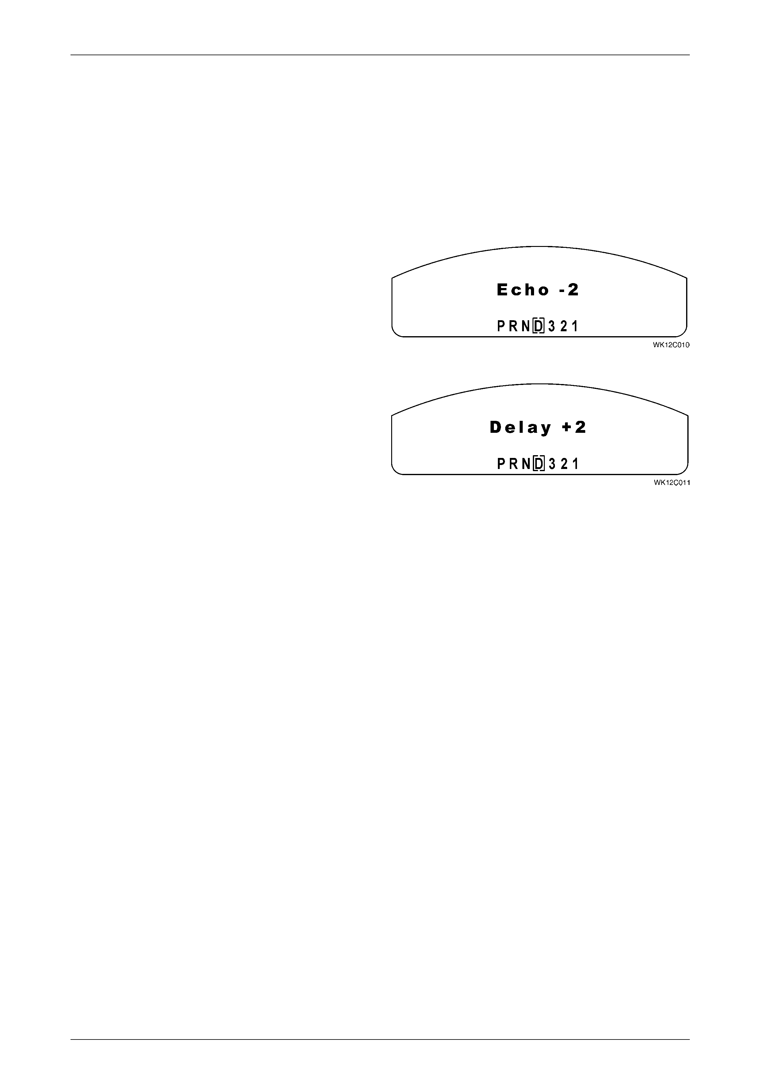
The following additional screens appear for the Level 5 WK Series.
Echo Settings
The range of Echo adjustment is from – 3 to + 3 with ‘0’
being the standard setting.
Figure 12C – 10
Delay Settings
The range of De lay adjustment is from – 3 to + 3 with ‘0’
being the standard setting.
Figure 12C – 11


Instruments Page 12C–13
Page 12C–13
1.9 Police Mode
If Police Mode is enabled via the TECH 2, the digital speedometer is the default display at ignition switch on. Police
Mode is a carry over from the MY2003 VY Series. Refer to Section 12C, 1.9 Police Mode in the MY2003 VY and
V2 Series Service Information for details.


Instruments Page 12C–15
Page 12C–15
2 Service Operations
IMPORTANT
All fasteners are important attaching parts as they affect the performance of vital components and/or could
result in major repair expense. Where specified in this section, fasteners MUST be replaced with parts of the
same part number or a GM approved equivalent. Do not use fasteners of an inferior quality or substitute
design.
Torque values must be used as specified during reassembly to ensure proper retention of all components.
Through out this section, fastener torque wrench specifications may be accompanied with the following
identification marks:
+
++
+ Fasteners must be replaced after loosening.
&
&&
& Vehicle must be at kerb height before final tightening.
6
66
6 Fasteners either have micro encapsulated sealant applied or incorporate a mechanical thread lock and
should only be re-used once. If in doubt, replacement is recommended.
If one of these identification marks is present alongside a fastener torque wrench specification, the recommendation
regarding that fastener must be adhered to.
CAUTION
Prior to commencing any of the following
procedures, disconnect the battery to disable
the Occupant Protection System. Reconnect
the battery on completion.
2.1 Instrument Cluster Trim Assembly
The removal and installation of the Instrument Cluster Trim Assembly is a carry over from the MY2003 VY Series. Refer
to Section 12C, 2.1 Instrument cluster Trim Assembly in the MY2003 VY and V2 Series Service Information for details.


Instruments Page 12C–17
Page 12C–17
2.3 Instrument Cluster Assembly
NOTE
Before replacing any instrument cluster assembly
that is suspected of being faulty, first carry out
instrument cluster input checks, refer to
2.4 Instrument Cluster Inputs in this Section.
If these tests prove that the inputs to the instrument cluster are OK, carry out checks of the gauge assemblies. Refer to
3.3 Ins trum ent Clust er Diagnos tics or 3.4 Diagnosing Faults Not Covered By Diagnostic Trouble Codes in Section 12C
Instruments in the MY2003 VY and V2 Series Service Information for further details. Following these steps will ensure
correct diagnosis of a system fault and needless replac ement of components that are not faulty.
The removal, disassembly, assembly and installation procedures for the Instrument Cluster are a carry over from the
MY2003 VY Series. Refer to Section 12C, 2.3 Instrument Cluster Assembly in the MY2003 VY and V2 Series Service
Information for details.
If a new instrument cluster has been installed, the original odometer reading, together with other important vehicle
parameters, must be programmed into the replacement instrument cluster. Refer to Section 12C, 3.15 Program in the
MY2003 VY and V2 Series Service Information for further details.
Techline

Instruments Page 12C–18
Page 12C–18
2.4 Instrument Cluster Inputs
Check
The following table provides details on the instrument cluster connector and signal functions. To check the input voltage
or wiring continuity between the various sensors / senders to the instrument cluster connector refer to Section 12 C,
3. Diagnostics in the MY2003 VY and V2 Series Service Information.
PIN NUMBER FUNCTION PIN NUMBER FUNCTION
X1-1 Battery X1-17 Ground
X1-2 Serial Data X1-18 Trip Computer Switch Return
X1-3 Brakes X1-19 Fuel Level Return
X1-4 Park Lamps X1-20 Ignition
X1-5 Speedometer X1-21 Cruise Control Active
X1-6 Tachometer X1-22 Left Seat Belt
X1-7 Spare X1-23 Right Seat Belt
X1-8 Door Ajar X1-24 Low Traction
X1-9 Front Fog Lamps X1-25 Spare
X1-10 Spare X1-26 Spare
X1-11 Right Turn Indicators X1-27 Cruise Control On
X1-12 High Beam X1-28 Trip Computer Switch
X1-13 Charging X1-29 Fuel Level
X1-14 ABS Off X1-30 LPG Fuel Level
X1-15 Left Turn Indicators X1-31 Security Warning
X1-16 PPD Sensor X1-32 PPD Sensor Low

Instruments Page 12C–19
Page 12C–19
2.5 Sender Units
Vehicle Speed Sender
The Vehicle Speed Sender is a carry over from the MY2003 VY Series. Refer to Section 12C, 2.5 Sender Units in the
MY2003 VY and V2 Series Service Information for details.
Fuel Gauge Sender Unit
The Fuel Gauge Sender Unit is a carry over from the MY2003 VY Series. Refer to Section 12C, 2.5 Sender Units in the
MY2003 VY and V2 Series Service Information for details.

Instruments Page 12C–21
Page 12C–21
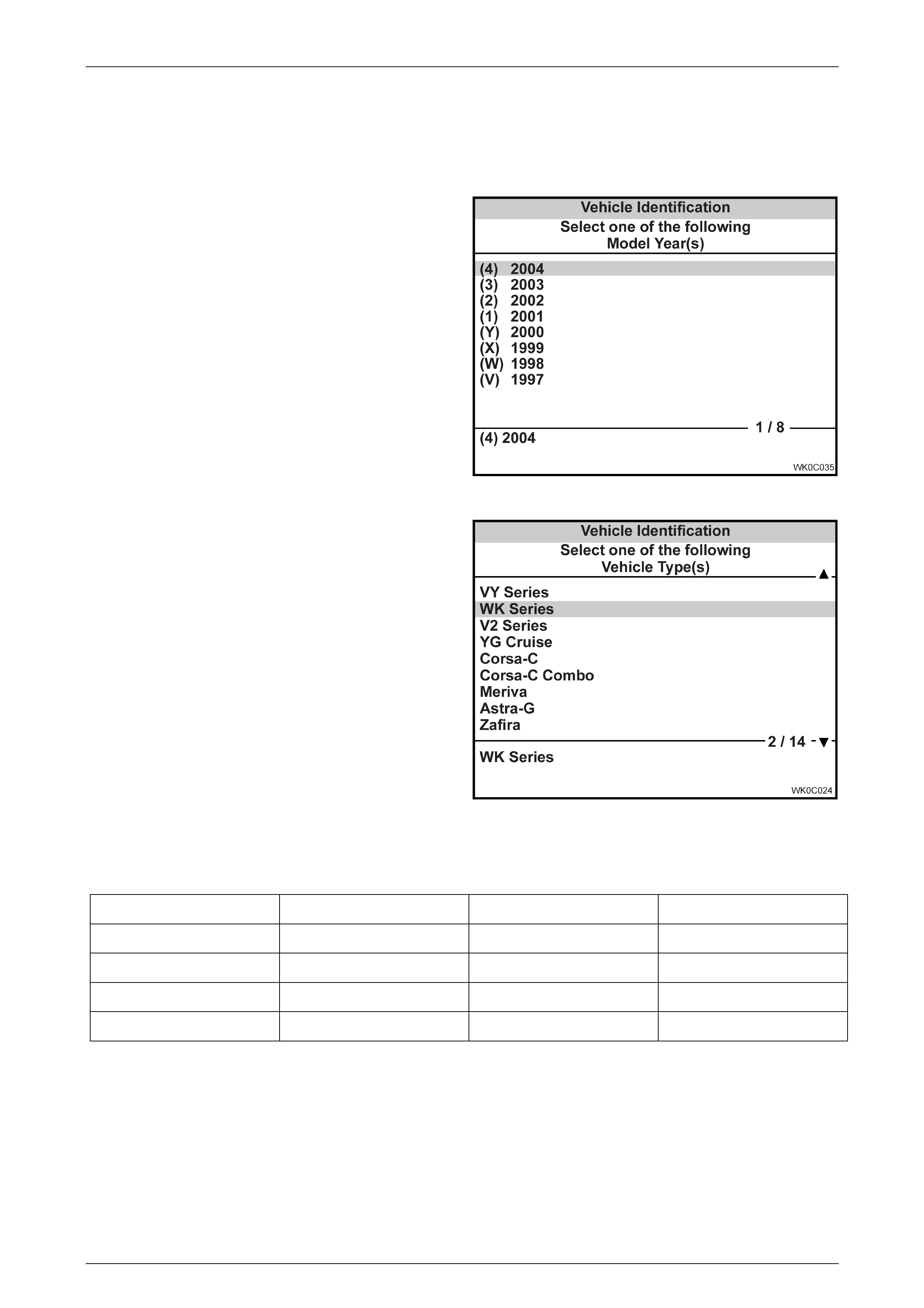
3 Diagnostics
The Diagnostic procedures are a carry over from the MY2003 VY Series except that the Model Year selection on
TECH 2 is now (4) 2004 and the Vehicle Type selection is WK Series.
Figure 12C-12
Figure 12C-13
If programming of Speedometer Pulses is required, use the following in formation:
Engine Transmission Tyre Size Speedometer Pulses
V6 or V8 Auto / Manual 225 / 60 R15 6238
V6 or V8 Auto / Manual 225 / 55 R16 6173
V6 or V8 Auto / Manual 225 / 50 R17 6100
V6 or V8 Auto / Manual 235 / 45 R17 6301
For further information on Instrument Cluster Diagnostics, refer to Section 12C Instruments in the MY2003 VY and V2
Series Service Information.