
Entertainment System Page 12D–1
Page 12D–1
Section 12D
Entertainment System
ATTENTION
Before performing any Service Operation or other procedure described in this Section, refer to Section 00
Warnings, Cautions and Notes for correct workshop practices with regard to safety and/or property damage.
1 General Information............................................................................................................................... 7
1.1 General Description ...............................................................................................................................................7
Audio System .........................................................................................................................................................7
Level 1 Models........................................................................................................................................................9
Level 2 and 3 Models ...........................................................................................................................................11
Level 4 Models......................................................................................................................................................12
Level 5 Models......................................................................................................................................................14
Multi Function Displa y.........................................................................................................................................16
Rear Seat Entertainment System........................................................................................................................16
DVD Player.......................................................................................................................................................17
Video Screens..................................................................................................................................................18
Hand-Held Remote Control ..............................................................................................................................18
Audio Interface Module.....................................................................................................................................19
DVD Output Splitter..........................................................................................................................................19
Rear Seat Headphones........................................................................................................................................20
Serial Data Bus.....................................................................................................................................................21
Security System ...................................................................................................................................................21
Audio System Parameters...................................................................................................................................21
Battery Disconnection.......................................................................................................................................21
Master Reset....................................................................................................................................................22
Telephone Audio ..................................................................................................................................................22
1.2 Power Antenna Operation ...................................................................................................................................23
1.3 Diversity Antenna Operation...............................................................................................................................25
1.4 Horn Bar Stereo Control Operation ....................................................................................................................26
Left-hand switch assembly (1)..........................................................................................................................26
Right-hand switch assembly (2)........................................................................................................................26
1.5 Rear Remote Control ...........................................................................................................................................28
1.6 Audio System Configuration...............................................................................................................................29
2 Service Operations.............................................................................................................................. 30
2.1 Audio System Head Unit......................................................................................................................................30
Remove .................................................................................................................................................................30
Reinstall ................................................................................................................................................................31
2.2 Instrument Panel Speakers – All Models ...........................................................................................................32
Remove .................................................................................................................................................................32
Reinstall ................................................................................................................................................................33
2.3 Front Door Speakers – All Models......................................................................................................................34
Remove .................................................................................................................................................................34
Reinstall ................................................................................................................................................................34
2.4 Rear Door Speakers.............................................................................................................................................36
Remove .................................................................................................................................................................36
Reinstall ................................................................................................................................................................36
2.5 Subwoofer Speakers – Level 4 and 5 Vehicles..................................................................................................37
Remove .................................................................................................................................................................37
Reinstall ................................................................................................................................................................37
Techline
Techline
Techline
Techline
Techline
Techline

Entertainment System Page 12D–2
Page 12D–2
2.6 Roof Mounted Speakers – Level 5 ......................................................................................................................38
Remove .................................................................................................................................................................38
Reinstall ................................................................................................................................................................38
2.7 Power Antenna.....................................................................................................................................................39
Power Antenna Switches.....................................................................................................................................39
Power Antenna Assembly ...................................................................................................................................39
Remove............................................................................................................................................................39
Reinstall............................................................................................................................................................40
Mast Replacement................................................................................................................................................41
Checking Antenna Motor Operation...................................................................................................................42
2.8 Diversity Antenna.................................................................................................................................................43
Diversity Antenna – Test......................................................................................................................................43
Diversity Antenna Module ...................................................................................................................................43
Remove............................................................................................................................................................43
Reinstall............................................................................................................................................................45
2.9 Horn Bar Stereo Controls....................................................................................................................................46
Remove .................................................................................................................................................................46
Reinstall ................................................................................................................................................................47
2.10 Subwoofer Amplifier ............................................................................................................................................48
Remove .................................................................................................................................................................48
Reinstall ................................................................................................................................................................48
2.11 Premium Sound Amplifier ...................................................................................................................................49
Remove .................................................................................................................................................................49
Reinstall ................................................................................................................................................................51
PSA Fuses.............................................................................................................................................................51
Remove............................................................................................................................................................51
Reinstall............................................................................................................................................................51
2.12 Rear Remote Control ...........................................................................................................................................52
Remove .................................................................................................................................................................52
Reinstall ................................................................................................................................................................52
2.13 Rear Audio Headphone Jacks.............................................................................................................................53
Remove .................................................................................................................................................................53
Reinstall ................................................................................................................................................................54
2.14 Dead Pan Assembly.............................................................................................................................................55
Remove .................................................................................................................................................................55
Reinstall ................................................................................................................................................................55
2.15 DVD Player............................................................................................................................................................56
Remove .................................................................................................................................................................56
Reinstall ................................................................................................................................................................56
2.16 Audio Interface Module ........................................................................................................................................57
Remove .................................................................................................................................................................57
Reinstall ................................................................................................................................................................57
2.17 DVD Splitter ..........................................................................................................................................................58
Remove .................................................................................................................................................................58
Reinstall ................................................................................................................................................................58
2.18 Video Screens.......................................................................................................................................................59
2.19 Audio System Security Code ..............................................................................................................................60
Code Entry............................................................................................................................................................60
Example:...........................................................................................................................................................60
2.20 Audio System Master Reset................................................................................................................................61
Reset Procedure...................................................................................................................................................61
3 Diagnostics........................................................................................................................................... 62
3.1 General Diagnostic Information..........................................................................................................................62
3.2 Principles Of Operation .......................................................................................................................................63
Radio Reception...................................................................................................................................................63
FM Reception In Vehicles....................................................................................................................................63
Australian Range..............................................................................................................................................64
Gulf States Range............................................................................................................................................64

Entertainment System Page 12D–3
Page 12D–3
Brazil Range, North / South America Range ....................................................................................................64
Asian Range, Israel Range, South Africa Range, Europe Range (without LW and RDS) ................................65
Thailand Range ................................................................................................................................................65
Band Selection .................................................................................................................................................65
Preset Station...................................................................................................................................................65
AM Reception In Vehicles....................................................................................................................................65
Basic Checks........................................................................................................................................................67
Common Radio Problems....................................................................................................................................68
Static.................................................................................................................................................................68
External Interference ........................................................................................................................................68
Internal Interference..........................................................................................................................................69
Diagnosing Internal Interference.......................................................................................................................70
Speakers ..........................................................................................................................................................70
3.3 Audio System Diagnostics..................................................................................................................................71
Diagnostic Trouble Codes...................................................................................................................................71
Audio System Input / Output Signals.................................................................................................................71
3.4 Connecting TECH 2 For System Diagnosis .......................................................................................................73
3.5 TECH 2 Test Modes And Displays ......................................................................................................................74
Main Menu.............................................................................................................................................................74
Model Year .......................................................................................................................................................74
Vehicle Identification Menu...............................................................................................................................74
System Selection Menu....................................................................................................................................75
Audio System Selection....................................................................................................................................75
Premium Sound Amplifier Selection .................................................................................................................77
Audio Interface Module Selection.....................................................................................................................79
DVD Player Selection.......................................................................................................................................81
3.6 Normal Mode – Audio System.............................................................................................................................83
F0: Normal Mode ..................................................................................................................................................83
Normal Mode Data List.....................................................................................................................................84
3.7 Diagnostic Trouble Codes – Audio System.......................................................................................................85
Read Current DTC Information............................................................................................................................85
Audio System Diagnostic Trouble Code List.....................................................................................................86
3.8 Diagnostic Data Displa y – Audio System...........................................................................................................87
F0: Data List..........................................................................................................................................................87
Data Display Data List......................................................................................................................................88
F1: System Identification.....................................................................................................................................90
3.9 Snapshot – Audio System...................................................................................................................................91
3.10 Miscellaneous Tests – Audio System.................................................................................................................92
Speed Dependent Volume...................................................................................................................................93
Priority Key Selection ..........................................................................................................................................93
Illumination...........................................................................................................................................................94
Antenna Selection................................................................................................................................................94
Antenna (Up / Down)............................................................................................................................................95
Security LED.........................................................................................................................................................95
Display ..................................................................................................................................................................95
Power (On / Off)....................................................................................................................................................96
Radio Band ...........................................................................................................................................................96
Preset Memory......................................................................................................................................................97
Audio.....................................................................................................................................................................97
CD Function..........................................................................................................................................................98
Eject CD.................................................................................................................................................................99
Audio Source........................................................................................................................................................99
3.11 Program – Audio System...................................................................................................................................101
F0: Program Code Index....................................................................................................................................101
F1: Program Antenna.........................................................................................................................................103
3.12 Audio System Diagnostic Procedures..............................................................................................................104
Introduction ........................................................................................................................................................104
Audio System Diagnostic Circuit Check..........................................................................................................108
Audio System Diagnostic Circuit Check Diagnostic Chart..............................................................................108
Diagnosing Faults Not Covered By Diagnostic Trouble Codes.....................................................................109

Entertainment System Page 12D–4
Page 12D–4
Power On / Off ....................................................................................................................................................110
Power On / Off Diagnostic Chart ....................................................................................................................110
No Sound Or Distorted Sound – Level 1 to 4 Vehicles ...................................................................................113
No Sound Or Distorted Sound Diagnostic Chart.............................................................................................114
No Sound Or Distorted Sound – Level 5 Vehicles...........................................................................................117
No Sound Or Distorted Sound Diagnostic Chart.............................................................................................118
Rear Seat Headphones No Sound ....................................................................................................................122
Rear Seat Headphones No Sound Diagnostic Table......................................................................................123
Rear Remote Control .........................................................................................................................................125
Rear Remote Control Diagnostic Chart ..........................................................................................................125
Audio Unit Display – Level 1 Vehicles..............................................................................................................127
Audio Unit Display Diagnostic Chart...............................................................................................................127
Multi Function Display – Level 2 to 5 Vehicles................................................................................................128
Multi Function Display Diagnostic Table.........................................................................................................128
Audio Head Unit Illumination ............................................................................................................................130
Audio Head Unit Illumination Diagnostic Chart...............................................................................................130
Hands-free Telephone Input..............................................................................................................................132
Hands-free Telephone Input Diagnostic Chart — Without Telematics............................................................132
Hands-free Telephone Input Diagnostic Chart – Without Telematics.............................................................133
Hands-free Telephone Input Diagnostic Chart – With Telematics..................................................................135
Electric Antenna – Full Up / Down....................................................................................................................138
Full Up / Down Electric Antenna Diagnostic Chart..........................................................................................139
Electric Antenna – Height Adjustable...............................................................................................................141
Height Adjustable Electric Antenna Diagnostic Chart.....................................................................................142
Single CD Player.................................................................................................................................................145
Single CD Player Diagnostic Chart.................................................................................................................146
CD Changer.........................................................................................................................................................147
CD Changer Diagnostic Chart........................................................................................................................147
Radio Reception.................................................................................................................................................149
Multipath Detector...........................................................................................................................................149
Treble Control.................................................................................................................................................149
Radio Reception Diagnostic Chart..................................................................................................................150
Subwoofer Amplifier..........................................................................................................................................153
Subwoofer Amplifier Diagnostic Chart............................................................................................................153
DTC 10 – Fascia Button Jammed......................................................................................................................156
Fascia Button Jammed Diagnostic Chart........................................................................................................156
DTC 11 – Steering Wheel Remote Button Jammed.........................................................................................157
Steering Wheel Remote Controls Diagnostic Chart........................................................................................157
DTC 21 – CD Mechanism Error (CD Changer Models Only) ...........................................................................159
CD Mechanism Error Diagnostic Chart...........................................................................................................159
DTC 22 – CD Play Error (CD Changer Models Only) .......................................................................................159
CD Play Error Diagnostic Chart......................................................................................................................159
DTC 24 – CD Loading Error (Single CD Models Only) .....................................................................................160
CD Loading Error Diagnostic Chart ................................................................................................................160
DTC 25 – CD Defect (Single CD Models Only) .................................................................................................160
CD Defect Diagnostic Chart............................................................................................................................160
DTC 26 – CD General Error (Single CD Models Only) .....................................................................................161
CD General Error Diagnostic Chart ................................................................................................................161
DTC 30 – Internal Bus Failure............................................................................................................................161
DTC 33 – Single Communication Bus Failure..................................................................................................161
DTC 34 – Multi Communication Bus Failure....................................................................................................161
DTC 35 – Fascia Communication Bus Failure .................................................................................................161
DTC 36 – DSP Failure (Level 5 vehicles only)..................................................................................................161
DTC 40 – No BCM Serial Data............................................................................................................................161
DTC 41 – No Class 2 Serial Data.......................................................................................................................162
Diversity Antenna Fault Diagnosis...................................................................................................................162
Diversity Antenna System Test Procedure......................................................................................................162
3.13 Diagnostic Trouble Codes – Premium Sound Amplifier.................................................................................164
Diagnostic Trouble Code History Data.............................................................................................................164
F0: Diagnostic Trouble Codes...........................................................................................................................164

Entertainment System Page 12D–5
Page 12D–5
Read DTC Information .......................................................................................................................................165
Premium Sound Amplifier Diagnostic Trouble Code List................................................................................165
3.14 Diagnostic Data Display – Premium Sound Amplifier.....................................................................................166
F0: Data List........................................................................................................................................................166
Data Display Data List....................................................................................................................................166
F1: System Identification...................................................................................................................................167
3.15 Snapshot – Premium Sound Amplifier.............................................................................................................168
3.16 Miscellaneous Tests – Premium Sound Amplifier...........................................................................................169
F0: PSA (On / Off)...............................................................................................................................................169
F1: Mute...............................................................................................................................................................170
F2: Gain...............................................................................................................................................................170
F3: Speaker.........................................................................................................................................................170
F4: Equaliser.......................................................................................................................................................171
F5: Dynamic Distortion Limiting.......................................................................................................................172
3.17 Program – Premium Sound Amplifier...............................................................................................................173
3.18 Premium Sound Amplifier Diagnostic Procedures .........................................................................................175
PSA Diagnostic Circuit Check...........................................................................................................................175
PSA Diagnostic Circuit Check Diagnostic Chart.............................................................................................176
PSA No Sound....................................................................................................................................................176
PSA No Sound Diagnostic Chart....................................................................................................................176
PSA No Power ....................................................................................................................................................177
PSA No Power Diagnostic Chart ....................................................................................................................177
DTC 1 – DSP Failure...........................................................................................................................................178
DTC 2 – EEPROM Failure ...................................................................................................................................178
DTC 3 – No Serial Data.......................................................................................................................................179
DTC 3 – No Serial Data Diagnostic Chart.......................................................................................................179
3.19 Diagnostic Trouble Codes – Audio Interface Module .....................................................................................180
Diagnostic Trouble Code History Data.............................................................................................................180
F0: Diagnostic Trouble Codes...........................................................................................................................180
Read Current DTC Information..........................................................................................................................181
Audio Interface Module Diagnostic Trouble Code List....................................................................................181
3.20 Diagnostic Data Display – Audio Interface Module.........................................................................................182
F0: Data List........................................................................................................................................................183
Data Display Data List....................................................................................................................................183
F1: System Identification...................................................................................................................................183
3.21 Snapshot – Audio Interface Module .................................................................................................................184
3.22 Miscellaneous Tests – Audio Interface Module...............................................................................................185
F0: DVD Illumination Level Control ..................................................................................................................186
3.23 Security – Audio Interface Module....................................................................................................................187
3.24 Audio Interface Module Diagnostic Procedures..............................................................................................188
AIM Diagnostic Circuit Check ...........................................................................................................................188
AIM Diagnostic Circuit Check Diagnostic Chart..............................................................................................189
AIM No Power.....................................................................................................................................................190
AIM No Power Diagnostic Chart.....................................................................................................................190
DTC 1 – No Class 2 Serial Data from DVD........................................................................................................190
No Class 2 Serial Data from DVD Diagnostic Chart.......................................................................................190
DTC 2 – DVD Not Initialised...............................................................................................................................192
No Serial Data From BCM Diagnostic Chart...................................................................................................192
DTC 3 – No Serial Data From BCM....................................................................................................................192
No Serial Data From BCM Diagnostic Chart...................................................................................................192
DTC 4 – No Serial Data From Audio System....................................................................................................193
No Serial Data From Audio System................................................................................................................193
DTC 7 – No Class 2 Serial Data.........................................................................................................................194
DTC 8 – Wrong Security Code (System Locked).............................................................................................194
DTC 11 – Class 2 Hardware Failure ..................................................................................................................194
Class 2 Hardware Failure Diagnostic Chart....................................................................................................195
DTC 12 – EEPROM Mirror Checksum Failed....................................................................................................195
EEPROM Mirror Checksum Failed Diagnostic Chart......................................................................................195
DTC 13 – EEPROM Checksum Failed...............................................................................................................195

Entertainment System Page 12D–6
Page 12D–6
3.25 Diagnostic Trouble Codes – DVD Player..........................................................................................................196
Read Current DTC Information..........................................................................................................................196
DVD Player Diagnostic Trouble Code List......................................................................................................196
3.26 Data Display – DVD Player.................................................................................................................................197
F0: System Identification...................................................................................................................................197
3.27 Snapshot – DVD Player......................................................................................................................................198
3.28 Program – DVD Player .......................................................................................................................................199
3.29 Security – DVD Player........................................................................................................................................201
3.30 DVD Player Diagnostic Procedures..................................................................................................................202
DVD Diagnostic Circuit Check ..........................................................................................................................202
DVD Diagnostic Circuit Check Diagnostic Chart.............................................................................................204
DVD No Power....................................................................................................................................................205
DVD No Power Diagnostic Chart....................................................................................................................205
DVD No Sound....................................................................................................................................................205
DVD Player No Sound Diagnostic Chart.........................................................................................................205
DVD Player No Picture.......................................................................................................................................206
DVD Player No Picture Diagnostic Chart........................................................................................................206
DTC B1000 – DVD Pla yer Malfunction..............................................................................................................207
DTC U1300 – Class 2 Serial Data Circuit Voltage Low....................................................................................207
DTC U1300 – Class 2 Serial Data Circuit Voltage Low Diagnostic Chart.......................................................207
DTC U1301 – Class 2 Serial Data Circuit Voltage High...................................................................................208
DTC U1301 – Class 2 Serial Data Circuit Voltage High Diagnostic Chart......................................................208
DTC U1128 No Audio Interface Module Serial Data.........................................................................................208
DTC U1128 No Audio Interface Module Serial Data Diagnostic Chart ...........................................................208
4 Specifications..................................................................................................................................... 209
VY System 1 Entertainment System.................................................................................................................209
VY System 3b Entertainment System...............................................................................................................209
WK System 3a Entertainment System..............................................................................................................209
WK System 4 Entertainment System................................................................................................................209
WK System 6 Entertainment System................................................................................................................210
Program Code Index Numbers..........................................................................................................................210
Audio System Identifier Number.......................................................................................................................210
5 Torque Wrench Specifications......................................................................................................... 211
6 Special Tools.................................................................................................................. .................... 212
Entertainment System Page 12D–7
Page 12D–7
1 General Information
This Entertainment System information is for MY 2004 WK Series vehicles. There are five levels of vehicle in the
WK Series Models. These are:
• Level 1 – Chevrolet Caprice LS,
• Level 2 – Chevrolet Caprice LTZ,
• Level 3 – Chevrolet Caprice SS,
• Level 4 – Holden Statesman, and
• Level 5 – Holden Caprice and Chevrolet Caprice Royale.
There are five levels of entertainment system, depending upon the vehicle model and / or options selected.
Entertainment System
Vehicle VY System 1 VY System 3b WK System 3a WK System 4 WK System 6
Level 1 Standard Optional – – –
Level 2 – – Standard – –
Level 3 – – Standard – –
Level 4 – – Standard –
Level 5 – – – – Standard
1.1 General Description
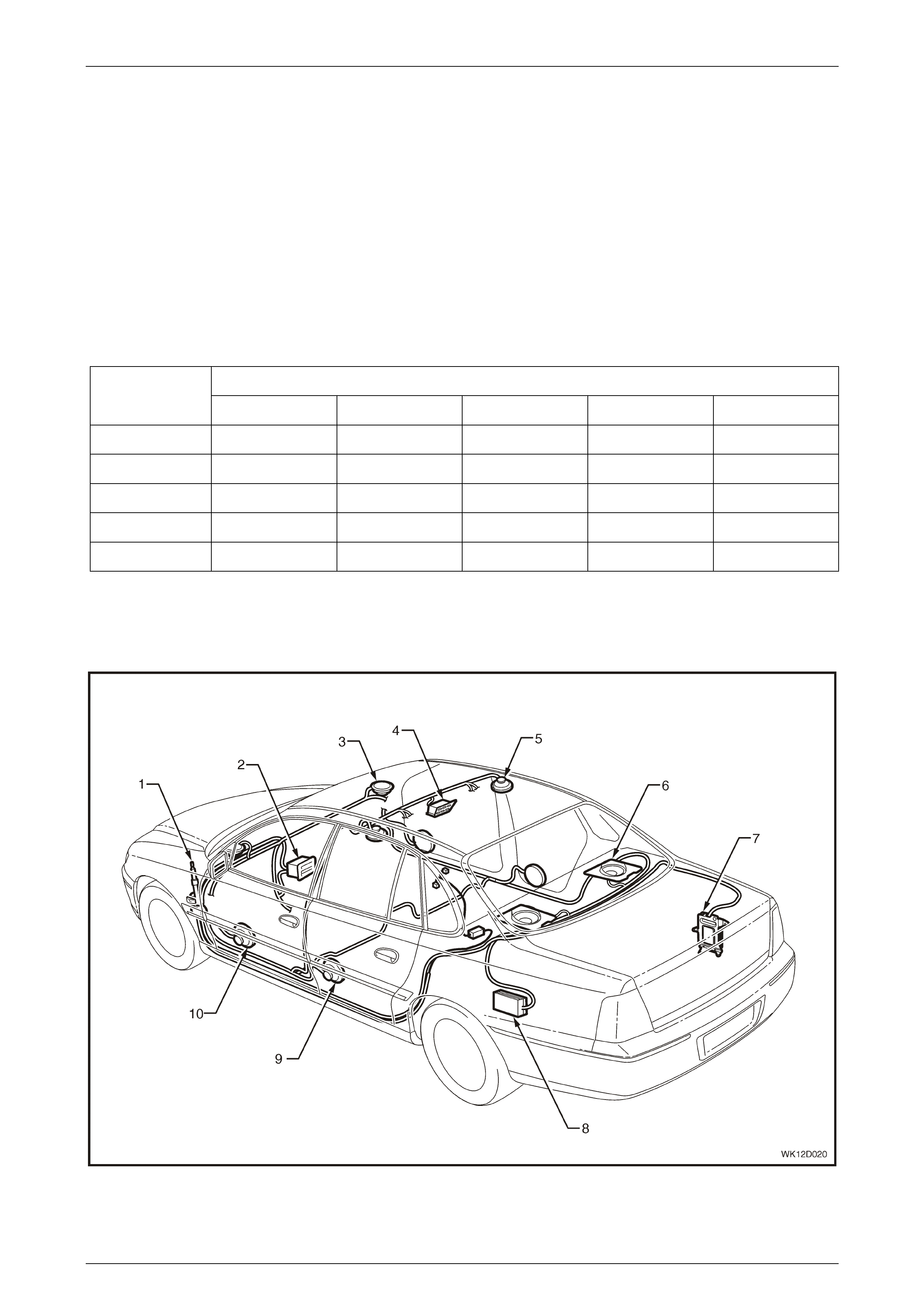
Audio System
Figure 12D – 1

Entertainment System Page 12D–8
Page 12D–8
Legend
1 Power Antenna
2 Audio Head Unit
3 Tweeter
4 Rear Remote Control (Level 5 only)
5 Roof Mounted Speaker (Level 5 only)
6 Subwoofer (Levels 4 and 5 only)
7 Premium Sound Amplif i er (Level 5 only)
8 Subwoofer Ampli fier (Level 4 onl y)
9 Rear Door Mounted Speaker
10 Front Door Mounted Speaker
MY 2004 WK Series Models are fitted with a high performance Blaupunkt Entertainment System that features an AM/FM
stereo tuner and either a single CD player or a six disc CD Changer depending on the Model and/or the level of audio
option installed. The entertainment system’s Audio Head Unit (AHU), which is mounted in the centre fascia of the
instrument panel, is equipped with a unique four-digit security code to protect against theft. A red LED incorporated in the
fascia of the AHU flashes when the security system is armed.
The features applicable to these audio systems will vary with the level of vehicle to which they are fitted. For Level 1
Models, a delete audio option is also available.
The radio in all models allows 6 AM / 12 FM stations to be preset and is prepared to enable the connection of a
hands-free mobile telephone kit. A clock, incorporated in the radio (Level 1 vehicles) or multi function display (Levels 2 to
5 vehicles), remains on display even when the ignition is turned off.
A full up / full down power antenna is standard on Level 1 vehicles and height adjustable power antenna is standard on
Level 2 to 5 vehicles.
Where fitted, the height adjustable power antenna is controlled by a switch on the radio fascia, in conjunction with the
Body Control Module (BCM). Refer to Section 12J Body Control Module in the MY 2003 VY and V2 Series Service
Information. For improved FM reception, all MY 2004 Level 4 and 5 Models are equipped with a diversity type antenna, in
addition to the adjustable height type antenna. The diversity antenna system consists of a diversity antenna, which is an
integral part of the rear window glass, and a diversity antenna module. Refer to 1.3 Diversity Antenna Operation in this
Section.
For all models, two tweeter type speakers are installed into the upper corner of the instrument dash panel and twin cone
speakers are installed into the front door trims. For MY 2004 WK Series Level 1 to 3 Models twin cone speakers are
fitted to the rear doors while for MY 2004 WK Series Level 4 and 5 Models co-axial speakers are fitted to the rear doors.
For MY 2004 WK Series Level 4 Models an additional pair of subwoofer type speakers are fitted to the rear parcel shelf
with an external subwoofer amplifier installed into the rear cargo compartment. For MY 2004 WK Series Level 5 models,
a pair of roof mounted speakers are fitted to the rear roof, a pair of subwoofer type speakers are fitted to the rear parcel
shelf and an external premium audio system amplifier is installed into the rear compartment.
If there is ever a customer concern, the subwoofer amplifier on Level 4 Models has a plastic screw to allow gain
adjustment for more or less presence (the centre detent position is the factory setting equivalent to VY Series).
For Level 4 Models, an AM/FM tuner and six disc CD Changer with subwoofers, external subwoofer amplifier and
adjustable height power type antenna are fitted as standard equipment.
For Level 5 Models, the premium audio system, consisting of an AM/FM tuner and six disc CD Changer, subwoofer
speaker s, external prem iu m audio amplifier, roof mounted s peak ers, rear roof mou nted re mote control, rear headphones
that connect to audio output jacks located beneath a flap in the rear parcel shelf and adjustable height power type
antenna are fitted as standard equipment. All MY 2004 WK Series Level 5 Models are also fitted with unique premium
quality front door, rear door and instru ment pan el tw eeter sp eaker s.
NOTE
The premium audio system is only available as
standard equipment on Level 5 Models.
In addition to the controls provided on the AHU (all Models) and roof mounted remote (Level 5 only), all MY 2004 WK
Series Models are fitted with steering wheel mounted audio switches, which allow limited control of the tuner and CD
player without the need for the operator to remove their hands from the steering wheel. Refer to 1.4 Horn Bar Stereo
Control Operation in this Section. The instrument cluster multi function display as well as the centre console mounted
multi function display provide an eye level screen that indicates the function selected at the horn bar switches.
The Priority Key feature available to MY 2004 WK Series Level 4 and 5 Models utilises two personal identity memories,
which individually memorise the following settings for different ignition keys:
• Radio On or Off
• Last used volume lev el
• Last used mode (AM, FM, CD or DVD)
• FM1– radio memory presets

Entertainment System Page 12D–9
Page 12D–9
• FM2 – radio memory presets
• AM – radio memory presets
• Power antenna height
• Bass, treble and loudness settings
• Speaker balance and fader setting
• CD track and disc sett ing s
• Confirmation beeps settings
• Equaliser and boost sett ings
• Telephone – volume, bass, treble, fader and balance settings (if a suitable hands free kit is connected to the audio
system)
• Speed dependant volu me setting
• Dynamic di storti on lim iti ng sett ing
For MY 2004 Level 5 vehicles, the following settings are also memorised:
• Listening position
• Digital signal processing sound effects including delay and echo settings
• Headphones on / off, last used mode and volume (only if headphones remain connected)
• Rear roof remote controls locked or unlocked
The radio’s priority settings will follow the priority key number broadcast by the BCM on the vehicle’s serial
communication data bus.
Operating instructions for the audio system either accompany or are part of the Owner’s Handbook in the vehicle’s
instrument panel compartment.
Level 1 Models
The following features are included in the audio entertainment system fitted to Level 1 Models:
• AM / FM 60 watt tuner / single CD player
• Two tweeters mounted in the instrument panel
• Four door mounted speakers
• LCD di splay in radi o
• Speed sensitive radio volume control
• Full up / full down power antenna
• Dynamic Distortion Limiter
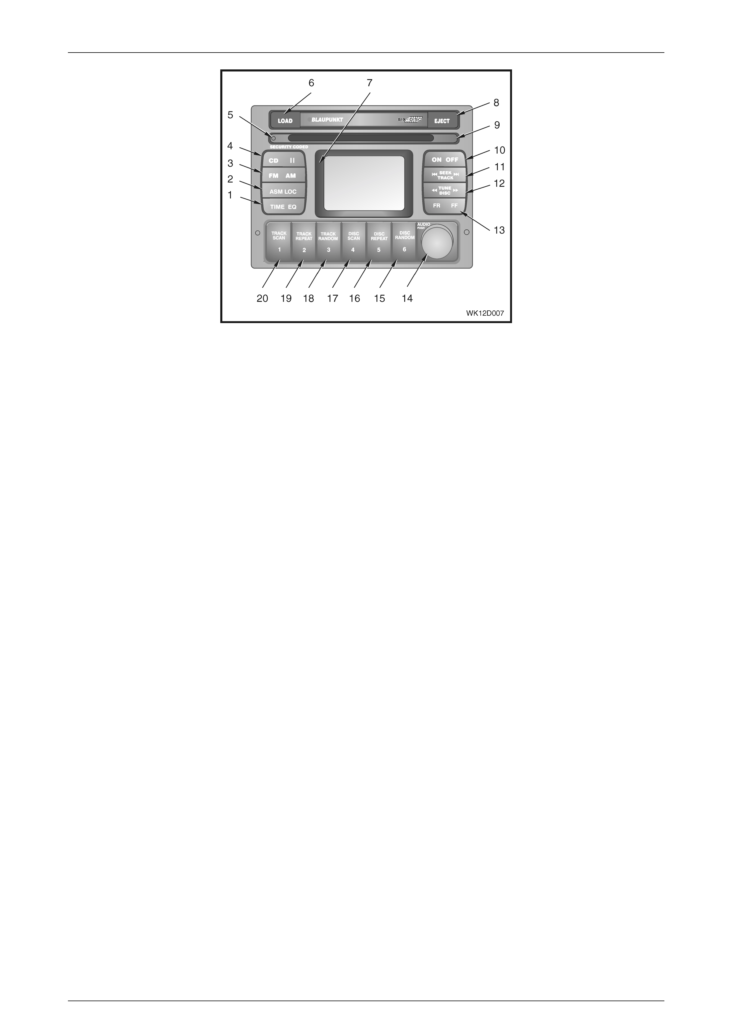
Figure 12D – 2 shows the System 1 radio / CD player fitted to Level 1 vehicles.

Entertainment System Page 12D–10
Page 12D–10
Figure 12D – 2
Legend
1 Clock adjustment / Time display on/of f
Mute
2 Automatic station memory storage
Local / distance search sensitivity
3 FM1 / FM2 / A M source button
4 CD source button
CD pause button
5 Security indicator light
6 Information display
7 CD eject button
8 Disc load / remove slot
9 Radio On / Off
10 Radio Mode: Station seek
CD Mode: Track up / down
11 Radio Mode: Manual frequency select
12 CD Mode: Track cue / review
13 Volume control
Push: Bass / Treble / Fader / Balance
14 Radio Mode: Memory pres et stati on 6
15 Radio Mode: Memory pres et stati on 5
16 Radio Mode: Memory pres et stati on 4
17 CD Mode: Track random
Radio Mode: Memory preset station 3
18 CD Mode: Track repeat
Radio Mode: Memory preset station 2
19 CD Mode: Track scan
Radio Mode: Memory preset station 1
An optional entertainment system can be fitted to Level 1 Models, which includes the following additional features:
• AM / FM tuner
• 60 watt amplification
• Six disc CD changer in head unit
• Preset equaliser
Entertainment System Page 12D–11
Page 12D–11
Figure 12D – 3
Legend
1 Clock adjustment / Time display on/of f
Equalizer On / Off setting
2 Automatic station memory storage
Local / distance search sensitivity
3 FM1 / FM2 / A M source button
4 CD source button
CD pause button
5 Security indicator light
CD Mode: Load, remove, wait indicator
6 CD load button
7 Information display
8 CD eject button
9 Disc load / remove slot
10 Radio On / Off
11 Radio Mode: Station seek
CD Mode: Track up / down
12 Radio Mode: Manual frequency select
CD Mode: Disc select
13 CD Mode: Track cue / review
14 Volume control
Push: Bass / Treble / Fader / Balance
15 CD Mode: CD Random
CD Mode: Disc 6 select
Radio Mode: Memory preset station 6
16 CD Mode: CD Repeat
CD Mode: Disc 5 select
Radio Mode: Memory preset station 5
17 CD Mode: CD Scan
CD Mode: Disc 4 select
Radio Mode: Memory preset station 4
18 CD Mode: Track Random
CD Mode: Disc 3 select
Radio Mode: Memory preset station 3
19 CD Mode: Track Repeat
CD Mode: Disc 2 select
Radio Mode: Memory preset station 2
20 CD Mode: Track Scan
CD Mode: Disc 1 select
Radio Mode: Memory preset station 1
Level 2 and 3 Models
The following features are included in the audio entertainment system fitted to Level 2 Models:
• AM / FM tuner
• 60 watt amplification
• Six disc CD changer in head unit
• Two tweeters mounted in the instrument panel
• Four door mounted speakers
• Speed sensitive radio volume control
• Height adjustable power antenna
• Preset equaliser
• Dynamic Distortion Limiter
• Multi Function Display – mounted in the Instrument Panel Centre Trim

Entertainment System Page 12D–12
Page 12D–12
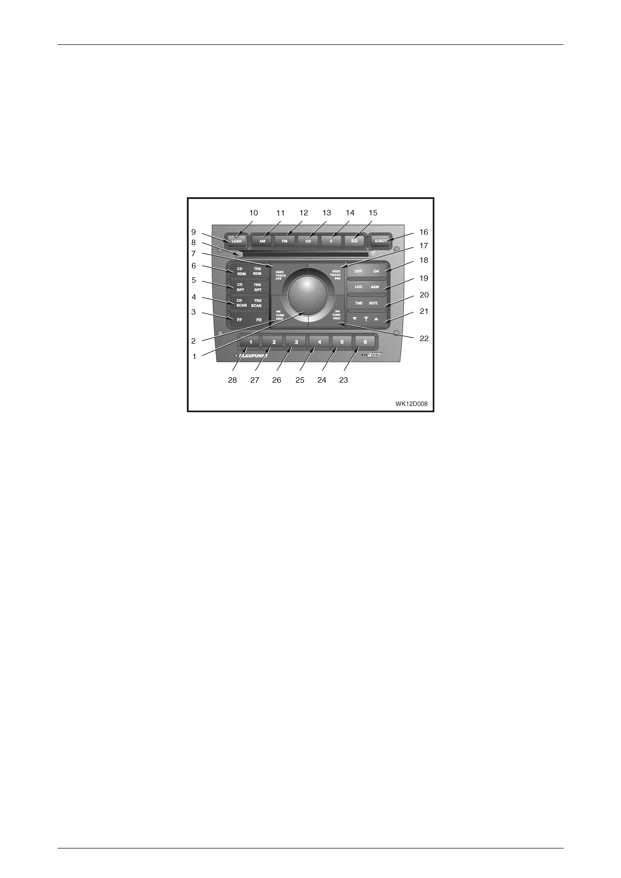
Figure 12D – 4
Legend
1 Volume control
Push: Bass / Treble / Fader / Balance / Loudness
adjustment
2 Radio Mode: Manual tuning down
CD Mode: Disc select down
3 CD Mode (push and hold): Track cue / review
4 CD Mode: CD scan
CD Mode: Track scan
5 CD Mode: CD repeat
CD Mode: Track repeat
6 CD Mode: Random disc play
CD Mode: Track random play
7 Radio Mode: Station seek down
CD Mode: Track down
8 Disc load / remove slot
9 CD load button
10 Security indicator light
CD Mode: Load / eject status light
11 AM source button
12 FM1 / FM2 source button
13 CD source button
14 CD pause button
15 Preset equaliser s elect button
16 CD eject button
17 Radio Mode: Station seek up
CD Mode: Track up
18 Power on / off
19 Automatic station memory storage (ASM)
Local / distance search sensitivity
20 Clock adjustment / Time display on/of f
Mute volume
21 Electric ant enna hei ght adj ustment
22 Radio Mode: Manual tuning up
CD Mode: Disc select up
23 CD Mode: Disc 6 select
Radio Mode: Memory preset station 6
24 CD Mode: Disc 5 select
Radio Mode: Memory preset station 5
25 CD Mode: Disc 4 select
Radio Mode: Memory preset station 4
26 CD Mode: Disc 3 select
Radio Mode: Memory preset station 3
27 CD Mode: Disc 2 select
Radio Mode: Memory preset station 2
28 CD Mode: Disc 1 select
Radio Mode: Memory preset station 1
Level 4 Models
The following features are included in the audio entertainment system fitted to Level 4 Models (refer to Figure 12D – 5):
• AM / FM tuner
• 260 watt amplification
• Six disc CD changer in head unit
• Priority key operation
• Two tweeters mounted in the instrument panel
• Four door mounted speakers
• Two rear mounted subwoofer speakers
Entertainment System Page 12D–13
Page 12D–13
• Subwoofer amplifier
• Diversity A ntenna
• Speed sensitive radio volume control
• Height adjustable power antenna
• Preset equaliser
• Dynamic Distortion Limiter
• Multi Function Display – mounted in the Instrument Panel Centre Trim
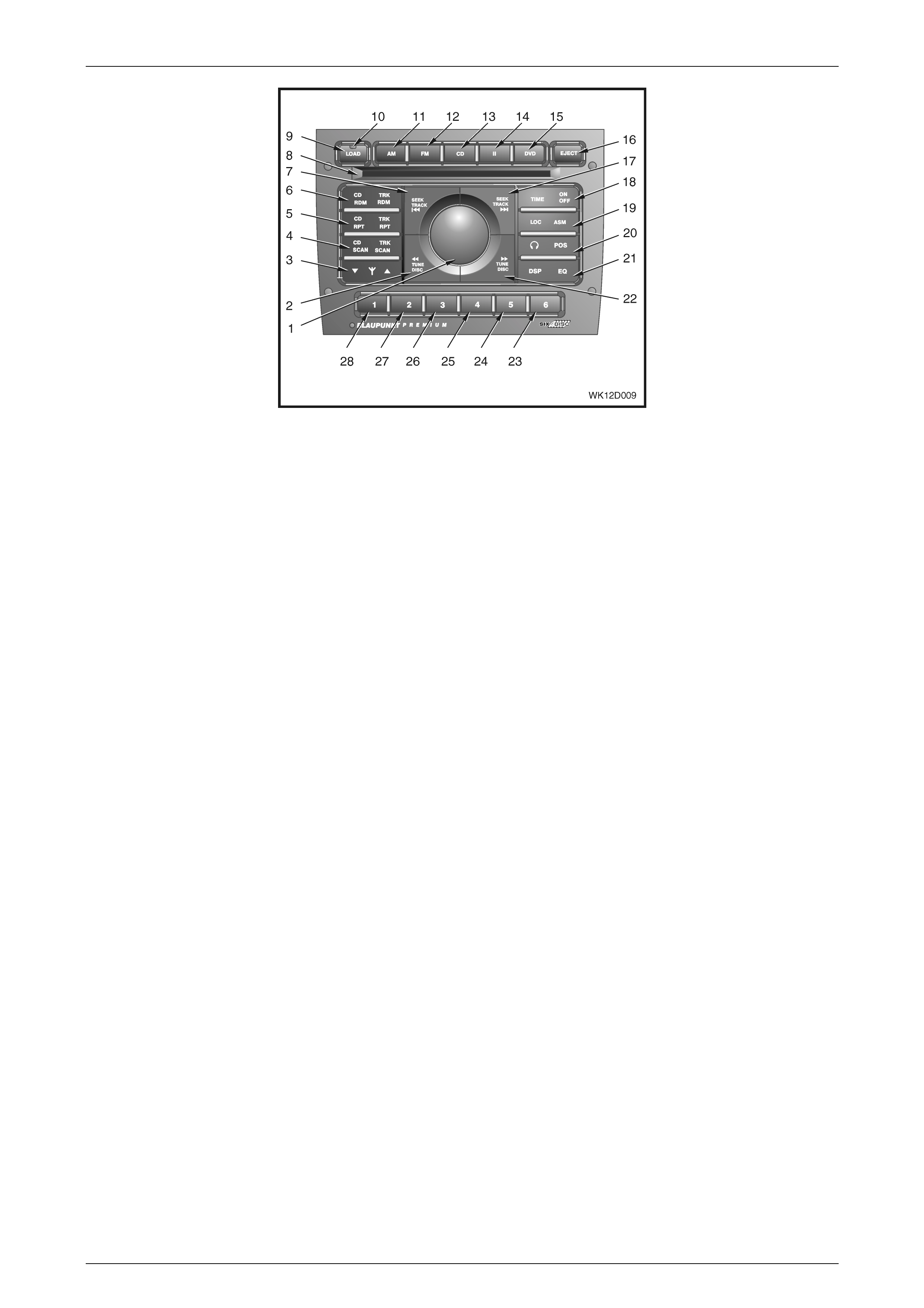
Figure 12D – 5
Legend
1 Volume control
Push: Bass / Treble / Fader / Balance / Loudness
adjustment
2 Radio Mode: Manual tuning down
CD Mode: Disc select down
3 CD Mode (push and hold): Track cue / review
4 CD Mode: CD scan
CD Mode: Track scan
5 CD Mode: CD repeat
CD Mode: Track repeat
6 CD Mode: Random disc play
CD Mode: Track random play
7 Radio Mode: Station seek down
CD Mode: Track down
8 Disc load / remove slot
9 CD load button
10 Security indicator light
CD Mode: Load / eject status light
11 AM source button
12 FM1 / FM2 source button
13 CD source button
14 CD pause button
15 Preset equaliser s elect button
16 CD eject button
17 Radio Mode: Station seek up
CD Mode: Track up
18 Power on / off
19 Automatic station memory storage (ASM)
Local / distance search sensitivity
20 Clock adjustment / Time display on/of f
Mute volume
21 Electric ant enna hei ght adj ustment
22 Radio Mode: Manual tuning up
CD Mode: Disc select up
23 CD Mode: Disc 6 select
Radio Mode: Memory preset station 6
24 CD Mode: Disc 5 select
Radio Mode: Memory preset station 5
25 CD Mode: Disc 4 select
Radio Mode: Memory preset station 4
26 CD Mode: Disc 3 select
Radio Mode: Memory preset station 3
27 CD Mode: Disc 2 select
Radio Mode: Memory preset station 2
28 CD Mode: Disc 1 select
Radio Mode: Memory preset station 1

Entertainment System Page 12D–14
Page 12D–14
Level 5 Models
The following features are included in the audio entertainment system fitted to Level 5 Models (refer to Figure 12D – 6):
• AM / FM tuner
• 430 watt amplification
• Six disc CD changer in head unit
• Priority key operation
• Two tweeters mounted in the instrument panel
• Four door mounted speakers
• Two rear mounted subwoofer speakers
• Two roof mounted speakers
• Premium six channel amplifier
• Multi Function Display – mounted in the Instrument Panel Centre Trim
• Diversity A ntenna
• Speed sensitive radio volume control
• Rear remote control
• Rear seat entertainment system
• Multi mode operation
• Rear seat headphones
• DSP (effects and listening position)
• Height adjustable power antenna
• Preset equaliser
• Dynamic Distortion Limiter
Entertainment System Page 12D–15
Page 12D–15
Figure 12D – 6
Legend
1 Volume control
Push: Bass / Treble / Fader / Balance / Loudness
adjustment
2 Radio Mode: Manual tuning down
CD Mode: Disc select down
3 Electric ant enna hei ght adj ustment
4 CD Mode: CD scan
CD Mode: Track scan
5 CD Mode: CD repeat
CD Mode: Track repeat
6 CD Mode: Random disc play
CD Mode: Track random play
7 Radio Mode: Station seek down
CD Mode: Track down
8 Disc load / remove slot
9 CD load button
10 Security indicator light
CD Mode: Load / eject status light
11 AM source button
12 FM1 / FM2 source button
13 CD source button
14 CD pause button
15 DVD source select butt on
16 CD eject button
17 Radio Mode: Station seek up
CD Mode: Track up
18 Clock adjustment / Time display on/of f
Power on / off
19 Automatic station memory storage (ASM)
Local / distance search sensitivity
20 Headphones select / desel ect / rear remote lock
Listening position select
21 Digital signal processor select
Preset equaliser select
22 Radio Mode: Manual tuning up
CD Mode: Disc select up
23 CD Mode: Disc 6 select
Radio Mode: Memory preset station 6
24 CD Mode: Disc 5 select
Radio Mode: Memory preset station 5
25 CD Mode: Disc 4 select
Radio Mode: Memory preset station 4
26 CD Mode: Disc 3 select
Radio Mode: Memory preset station 3
27 CD Mode: Disc 2 select
Radio Mode: Memory preset station 2
28 CD Mode: Disc 1 select
Radio Mode: Memory preset station 1
Entertainment System Page 12D–16
Page 12D–16
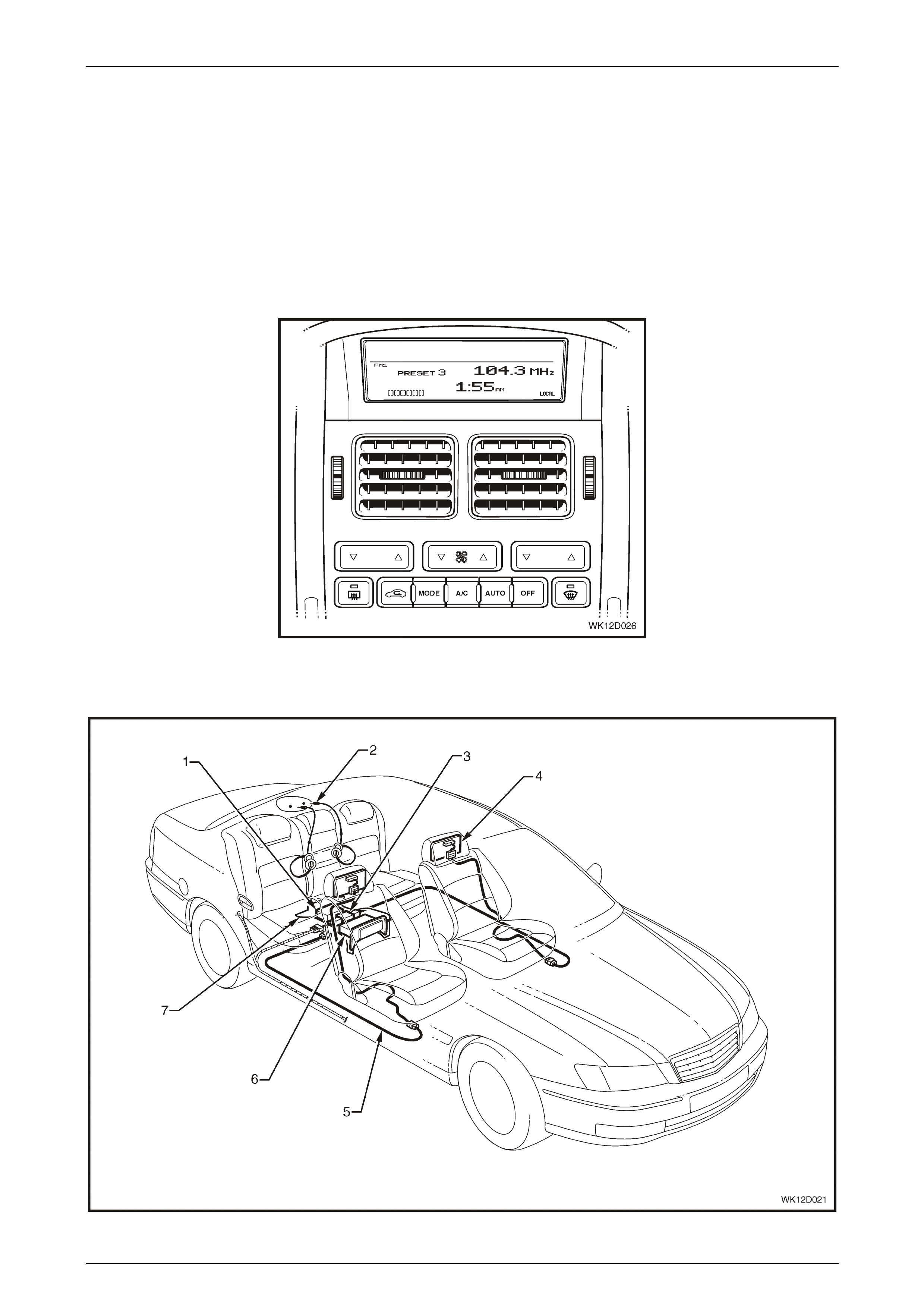
Multi Functi on Display
Figure 12D – 7 shows the Multi Function Display (MFD) module that is fitted to all LHD Level 2 to 5 and RHD Level 4 and
5 MY 2004 WK Series vehicles. The Audio Head Unit's (AHU) active functions and audio settings are displayed on the
lower portion of the MFD screen. The MFD is also used to display current time and Occupant Climate Control settings.
These are displayed on the upper portion of the MFD screen. A line running across the screen of the MFD divides these
two groups of information. In the event that the AHU develops a fault there is no self-diagnostic symbol displayed on the
MFD.
The MFD is located above the face level centre vents and is attached to the back of the instrument panel centre trim
assembly.
For further information relating to the MFD, including how to set the clock without the AHU installed, refer to Section 12I
Multi Function Display in this Service Information.
Figure 12D – 7
Rear Seat Entertainment Syst em
Figure 12D – 8
Entertainment System Page 12D–17
Page 12D–17
Legend
1 Audio Interface Module (AIM)
2 Rear seat headphones
3 DVD output splitte r
4 Video screen
5 Video screen harness
6 DVD player
7 Dead pan assembly
All MY 2004 WK Series Level 5 Models are fitted with a Digital Versatile Disc (DVD) Rear Seat Entertainment (RSE)
system. The RSE system includes a DVD player, two video display screens, an Audio Interface Module (AIM), a DVD
output splitter device and a hand-held remote control unit stored in the rear seat centre armrest storage compartment.
The AIM, DVD output splitter and DVD player are housed in a dead pan assembly under the rear seat. Figure 12D – 8
shows the location of the components of the RSE.
The RSE also provides stereo RCA jacks mounted into the faceplate of the DVD player unit. The RCA jacks allow
connection of audio and video inputs from an auxiliary device such as a camcorder or video game player to the video
screen using standard RCA cables, just as for a standard television. The yellow jack is the video input, while the red and
white jacks provide right and left stereo audio respectively.
To use the auxiliary inputs on the RSE system, connect the external auxiliary device to the colour-coded jacks and switch
the power to both the auxiliary device and the RSE system on. If the RSE system is still in DVD player mode, the user
will need to change the RSE to auxiliary mode by pressing the SRCE button on either the faceplate of the DVD player or
the hand-held remote control. Successive operation of the SRCE button will toggle the RSE system between DVD player
and auxiliary modes.
The RSE system is also capable of outputting audio to the vehicle audio system speakers and the rear seat headphone
jacks mounted under the flap on the rear window trim panel assembly. This is done by utilising the controls on the AHU
or the steering wheel or the rear remote controls. Once the RSE system is selected as an audio source on the AHU, the
RSE volume can be set by adjusting the radio volume control at either the AHU or the roof-mounted remote control.
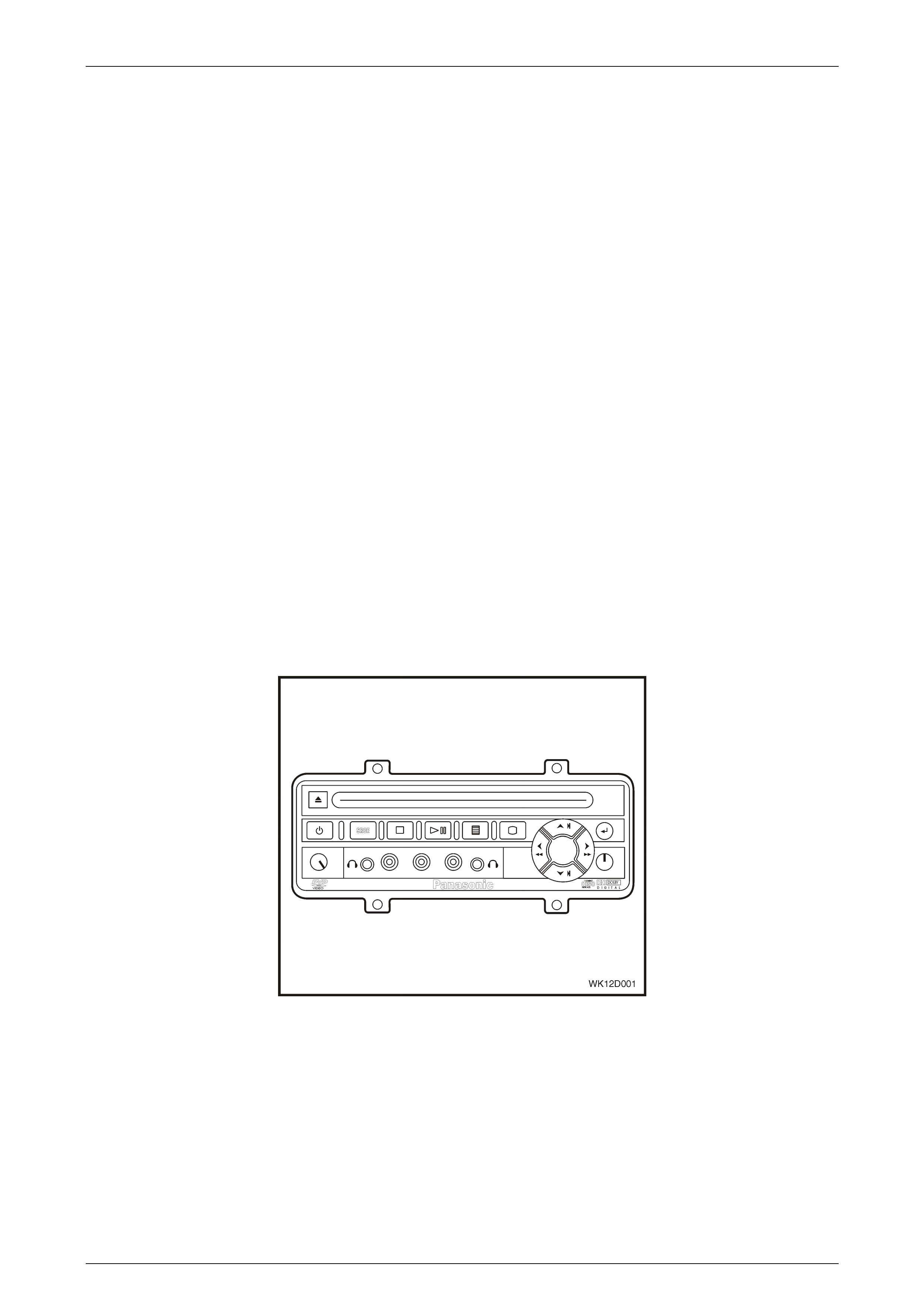
DVD Player
The DVD player (refer to Figure 12D – 9) is located in a mounting bracket under the centre of the rear seat. The DVD
player is only compatible with DVDs of the appropriate DVD region code for the country the vehicle was sold in. The DVD
region code is printed on the jacket of most DVDs. In addition to DVDs, the player will also play audio Compact Discs
(CDs), however, it will not play home recorded CDs (CD-R or CD-RW formats).
Figure 12D – 9
Entertainment System Page 12D–18
Page 12D–18
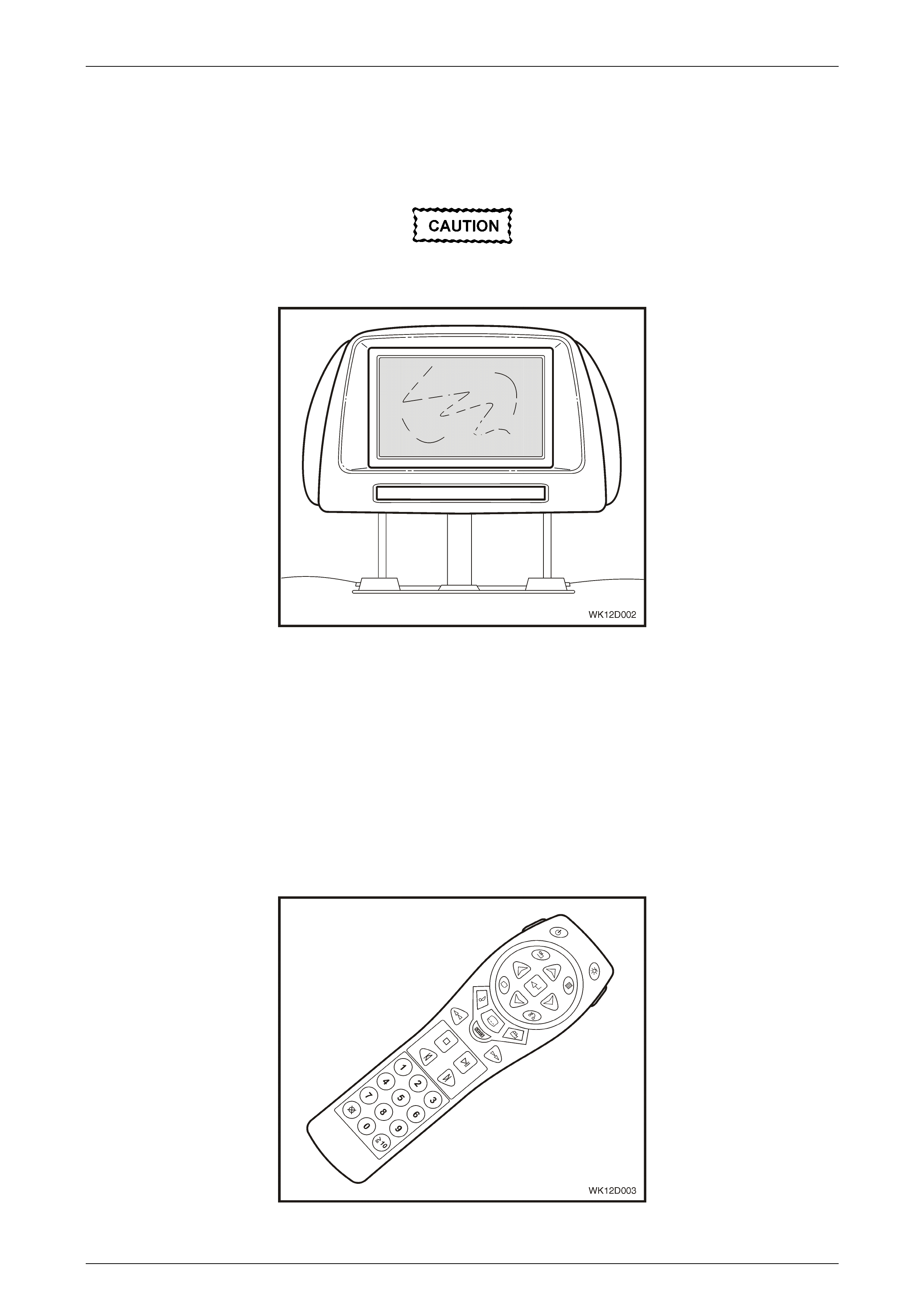
Video Screens
The video display screens (refer to Figure 12D – 10) are mounted into the rear of the front seat head restraints, and
include an infra-red receiver located directly beneath the screen for communication with the hand-held remote control
unit. For correct operation of the hand-held remote control unit, the line of sight to the video display screen MUST be
kept clear.
Avoid directly touching the video display
screens, as damage to the screen may occur.
Figure 12D – 10
Hand-Held Remote Control
The hand-held remote control unit (refer to Figure 12D – 11) is powered by two AA batteries, and provides control of all
functions for the DVD player. To use the hand-held remote control, aim it at the infra-red window at the bottom of the
video display screen and press the desired button.
NOTE
Direct sunlight or very bright light interferes with
the RSE systems ability to receive signals from
the hand-held remote control.
If the hand-held remote control does not seem to be working, the most likely cause is flat batteries.
Figure 12D – 11
Entertainment System Page 12D–19
Page 12D–19
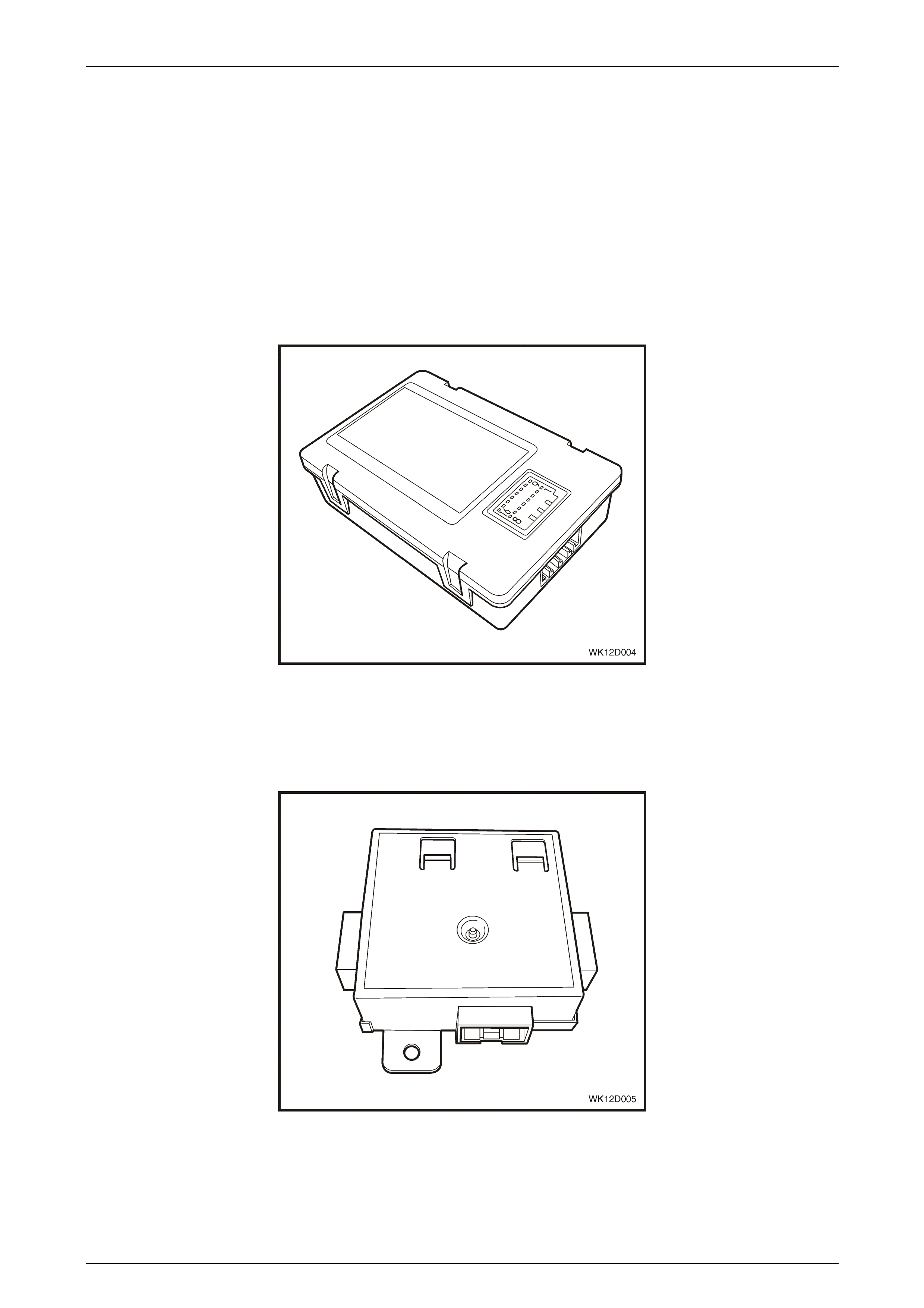
Audio Interface Module
The Audio Interface Module (AIM, refer to Figure 12D – 12) is located in a mounting bracket under the centre of the rear
seat along with the DVD player and video splitter.
The AIM acts as an interface between the DVD player and the audio system and BCM. The AIM enables the DVD to
power up by verifying BCM security information from the Radio message on the UART data bus and then communicating
to the DVD via the Class II communications bus. Without the valid security information, the AIM will go into Lock mode
and not allow the DVD to power up.
The AIM also controls the parental lockout feature. This feature is activated by pressing the headphone button on the
AHU for more than two seconds. While in parental lockout mode, all DVD functions except for load / eject DVD are
disabled. The rear remote controls are also locked when this parental lockout is activated. Normal operation of the DVD
player and rear remote control is restored by pressing the headphone button for more than two seconds.
Figure 12D – 12
DVD Output Splitter
The DVD output splitter (refer to Figure 12D – 13) is located in a mounting bracket under the centre of the rear seat
along with the DVD player and AIM.
Figure 12D – 13

Entertainment System Page 12D–20
Page 12D–20
Rear Seat Headphones
Level 5 vehicles are fitted with rear seat headphone jacks located under a hinged cover in the centre of the rear window
trim panel assembly, positioned on either side of the child restraint anchor point (refer to Figure 12D – 14). The sockets
fitted to the parcel shelf are standard 6.5 mm size that suit a wide variety of headphones. Two sets of headphones are
supplied with the vehicle when new (refer to Figure 12D – 15). Insertion of one or both headphones into the audio output
jacks mutes the audio output from the rear speakers and switches the audio signal to the headphones.
NOTE
Two 3.5 mm jacks are incorporated into the front
of the DVD player. Suitable headphones are not
provided with the vehicle, as they do not support
the multi-mode rear seat audio operation. The
auxiliary headphones operate independently of
the audio system and only provide output of DVD
or auxiliary devices connected to the DVD player
RCA jacks.
Figure 12D – 14
Figure 12D – 15

Entertainment System Page 12D–21
Page 12D–21
When the supplied headphones are plugged in, multi-moding of the audio system is possible via the rear remote controls
(refer to 1.5 Rear Remote Control in this Section). That is, whichever function is not being used by the occupants of the
front seats can be used by the occupants of the rear seats and vice-versa. This can only be achieved while the
headphones are plugg ed in.
If the headphones have been inadvertently left plugged in, audio from the rear speakers can be regained without the
need for the driver to stop the vehicle and physically remove the headphones from the jacks. Toggling the switch
(marked with the image of headphones, (item 20), refer to Figure 12D – 6) on the radio fascia enables the driver or front
seat passenger to obtain audio output from the rear speakers while the headphones remain plugged in.
NOTE
Activating the headphones disables the digital
signal processing and listening position functions
if they are turned on (Level 5 vehicles only).
Serial Data Bus
The audio system is connected to the main vehicle serial data bus and communicates with other modules on the bus.
Some audio system settings can be displayed on the Multi-function Display located in the instrument cluster, and this
information is transmitted via the serial data bus. Additionally, the instrument cluster Customisation Mode allows the
adjustment of some audio system settings from the instrument cluster.
For Level 2 and higher vehicles, the serial data bus transmits all audio settings to the Multi Function Display (MFD),
located in the instrument panel centre trim via the secondary serial data bus.
When the audio system is switched off at the front panel switch, power is still applied to the unit to maintain serial data
bus commu nic ati ons.
Security System
The audio system is protected by a security system, which flashes a red LED on the front fascia when activated. In
addition, the audio system is protected against theft by a four-digit security code that is unique to each unit.
The audio system communicates with other modules such as the BCM and the instrument cluster on the UART serial
data bus. If the audio system head unit is removed for any reason, upon installation the audio system interrogates the
other modules to determine if the same modules are fitted and therefore the system or vehicle is the same. If the audio
system recognises the other modules the audio system will operate. However, if the audio system detects a mismatch in
the serial numbers of some of the other modules, the audio system will remain in secure mode indefinitely. Entry of the
correct security code via the head unit preset keys will enable operation and authorise a new link up of the modules on
the serial data bus.
The instrument cluster monitors communication over the serial data bus. If a different AHU is fitted to the vehicle, and
this AHU is not connected to the bus, the Data Trouble Code (DTC) associated with the audio system may be
permanently set. This fault does not have a visible telltale on the instrument cluster.
The AIM provides a secondary security feature. The AIM enables the DVD to power up by verifying BCM security
information from the Radio message on the UART data bus and then communicating to the DVD via the Class II
communications bus. Without the valid security information, the AIM will go into Lock mode and not allow the DVD to
power up. The AIM can be linked to the BCM via TECH 2.
Au dio System Parameters
Battery Disconnection
Disconnecting the vehicle battery for service operations does not impact on the driver selectable audio system
parameters.

Entertainment System Page 12D–22
Page 12D–22
Master Reset
The audio system parameters can be reset to the factory default settings from either the instrument cluster in
Customisation Mode or from the audio unit front fascia. For the reset procedure, refer to 2.20 Audio System Master
Reset in this Section. The factory default settings are as follows.
Parameter Range Default
Bass –6 to +6 STD (0)
Treble –6 to +6 STD (0)
Balance –6 to +6 STD (0)
Fader –6 to +6 STD (0)
Loudness On / Off On
Equaliser On / Off Off
Boost -2 to +2 STD (0)
CD Random On / Off Off
CD Repeat On / Off Off
Local / Distance Local / Distance Distance
Display Mode Clock Adjust / Time Time
Audio Distortion
Limiter On / Off On
Confirmation
Beeps All On / CD Only /
Off All beeps On.
Speed Dependent
Volume 0 to 5 2
Telephone Audio
The audio system head unit provides two inputs for telephone audio, which allows the telephone audio to use the audio
system speakers. A mute signal from the telephone mutes the normal audio or pauses the CD when required. The audio
system display shows VOICE IN when the telephone is in use. When the call ends, the audio system returns to the
previous playing mode and audio settings. For more details, refer to Section 12G Cellular Phone in this Service
Information.
Telematics (if fitted) also uses these circuits for muting normal audio and providing telematics audio through the vehicle's
speakers. For more details on telematics refer to Section 12K Telematics in the MY 2003 VY and V2 Series Service
Information.

Entertainment System Page 12D–23
Page 12D–23
1.2 Power Antenna Operation
There are two power antenna options available. These are:
• Full up / down antenna, or
• Height adjusta ble antenna .
For vehicles with the full up / down power antenna option, the radio / CD player controls the operation of the antenna
(refer to Figure 12D – 16). Battery voltage is applied at all times to the antenna motor via circuit 1040, which is protected
by the RADIO fuse F23. Antenna operation is controlled from the audio system by the Radio On signal, which controls
the internal antenna control relay via circuit 314. When the radio is switched on, the antenna mast is raised to its full
height, and retracts when the radio is switched off or a CD is played.
Figure 12D – 16
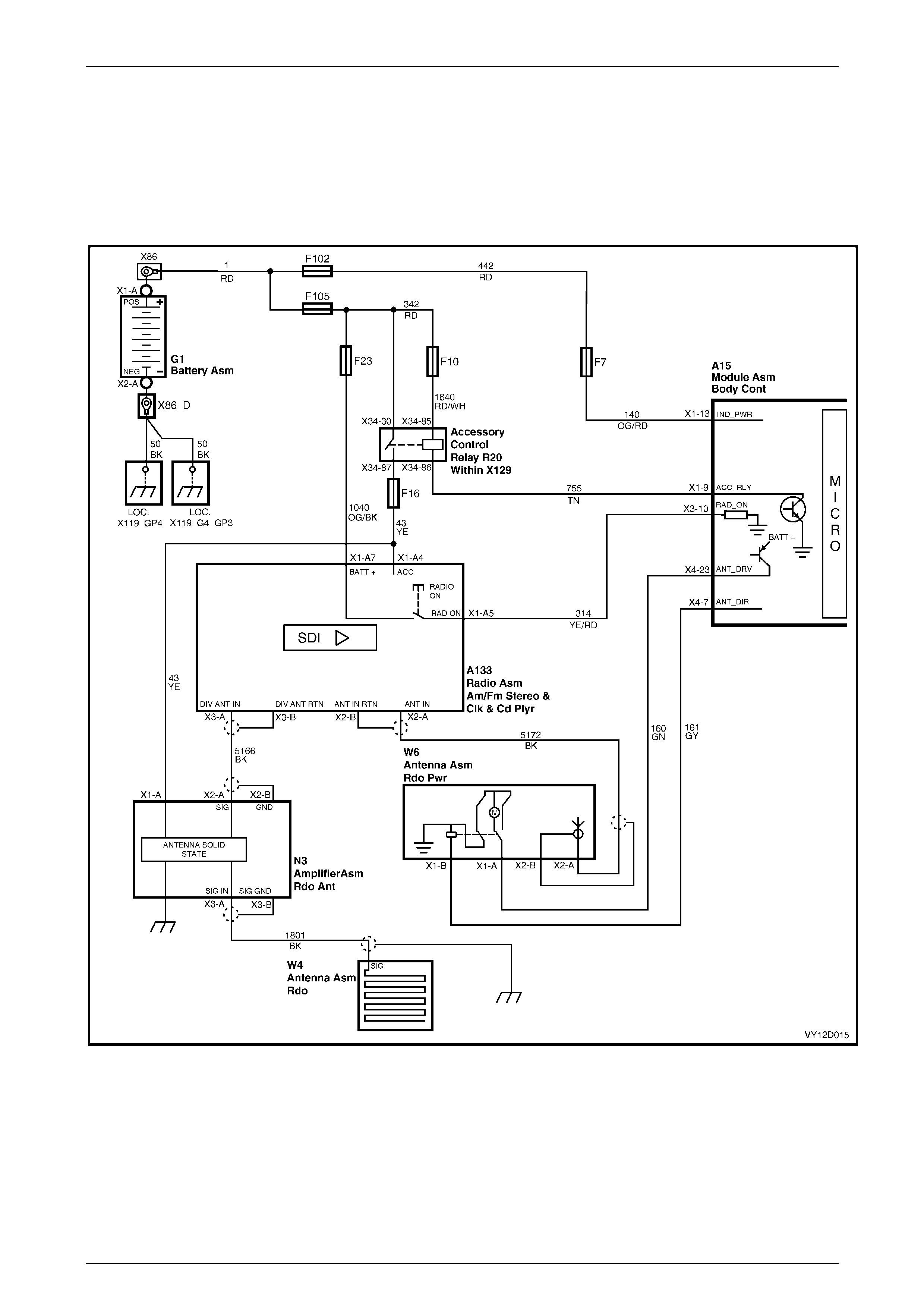
Entertainment System Page 12D–24
Page 12D–24
For vehicles with the height adjustable power antenna option, the BCM and the height adjustment switch located on the
radio / CD player control panel, adjacent to the liquid crystal display, control the operation of the power antenna (refer to
Figure 12D – 17). The adjustable height antenna is under direct control of the BCM. The audio system Radio On signal
on circuit 314 is applied to the BCM on terminal X3-10 and, together with information on the serial data bus, instructs the
BCM to raise or lower the antenna. Antenna motor power is supplied via the BCM (terminal X4-23) and is applied to the
antenna via circuit 160. Antenna direction control is also controlled by the BCM (terminal X4-7) and is applied to the
internal antenna control relay via circuit 161. The HAZARD LAMPS / ANTENNA DRIVE fuse F7 protects the antenna
motor power circuit. For further information refer to Section 12J, Body Control Module in the MY 2003 VY and V2 Series
Service Information.
Figure 12D – 17

Entertainment System Page 12D–25
Page 12D–25
1.3 Diversity Antenna Operation
To aid in the consistent reception of FM radio signals, the Level 4 and 5 vehicles are equipped with a diversity antenna
system.
The diversity antenna system consists of a diversity antenna W4, a diversity antenna amplifier N3 and coaxial leads.
Refer to Figure 12D – 17 for the diversity antenna interconnection details.
The diversity antenna is an integral part of the rear window glass. The thin conductors that form the diversity antenna are
laid on the inside of the glass in the same manner as the rear window demister elements. A terminal is located on the
passenger side of the rear window allowing connection of the diversity antenna to the diversity antenna module lead.
The diversity antenna module amplifies the small signals from the diversity antenna to signals of similar strength as the
signals from the main (mast) antenna. It then transmits the amplified signal to the radio’s diversity antenna input.
The diversity antenna module is located beneath the trim on the passenger's side of the rear window trim panel
assembly. The module is connected to the diversity antenna via one of two coaxial leads, the other lead, located under
the passenger side rocker panel cover, connects the module to the radio’s diversity antenna input extension lead.
Another single wire lead is used to supply the diversity antenna module with 12 Volts for its operation via Fuse F16, and
the module is grounded through its case to the vehicle body. To prevent interference, it is very important that the module
and coaxial leads are grounded securely.
The radio receives signals from both the diversity antenna system and the conventional fender mounted mast type
antenna. Internal circuitry within the radio decides which antenna is located in the cleaner signal area. It then uses that
antenna for its radio reception.
When the vehicle is in motion the radio constantly monitors the inputs from both antennas and swaps between them in
order to maintain the best possible radio reception.
NOTE
The diversity antenna system does not work in
weak signal areas. It is designed for improving
performance under multi-path conditions. Refer to
3.1 General Diagnostic Information in th is S ec ti o n
for more information on multi-pathing.
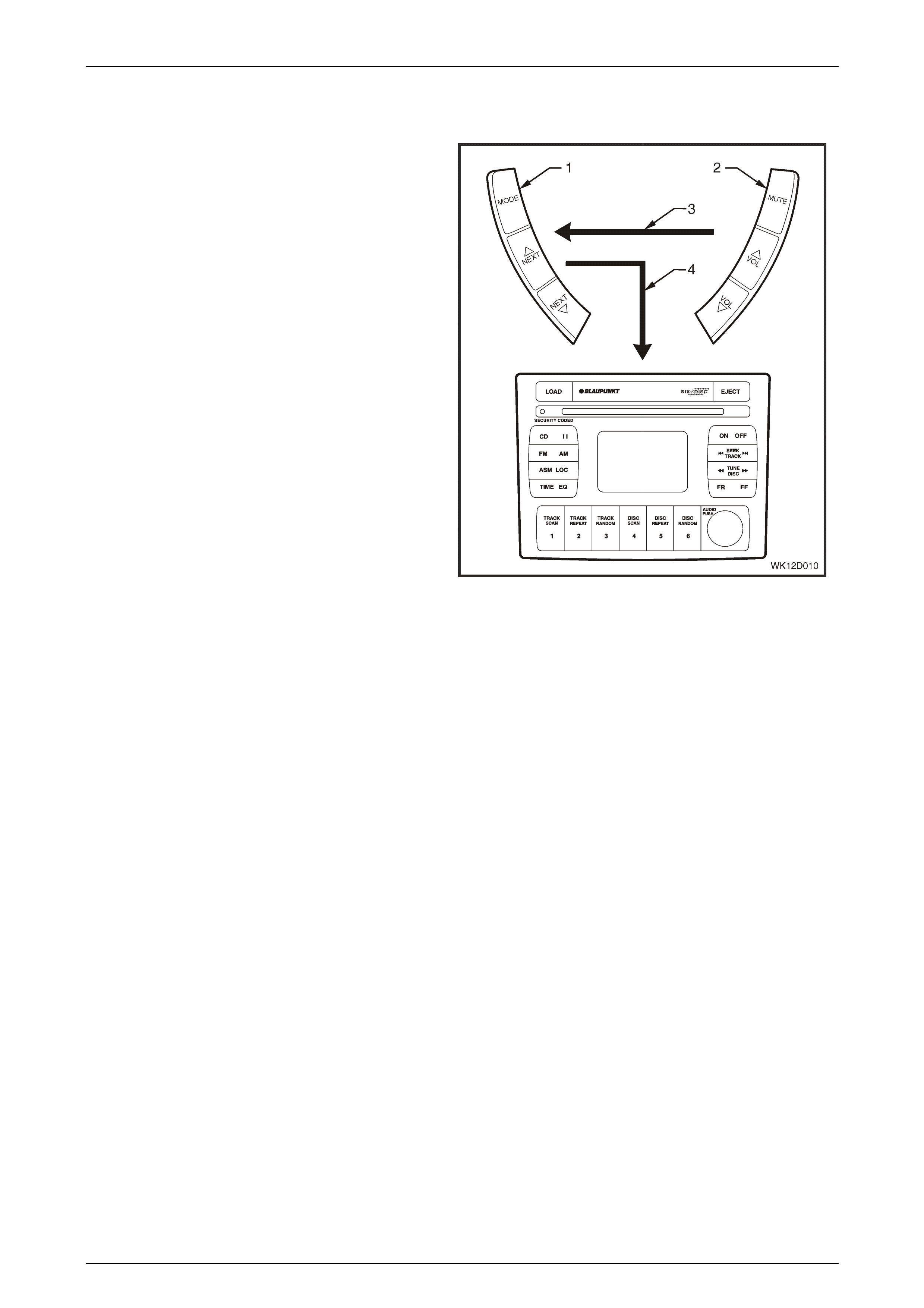
Entertainment System Page 12D–26
Page 12D–26
1.4 Horn Bar Stereo Control Operation
There are two major components of the horn bar stereo
control system. These components are as follows:
Left-hand switch assembly (1)
Located to the left-hand side of the horn bar, the left-
hand switch assembly has three momentary contact
switches that are used to control the mode of operation
and switchin g between pres et stations.
The MODE button allows selection between the Radio
Mode of operation and the CD Mode.
If Radio Mode is selected, the NEXT UP button selects
the next preset station in the frequency band, while the
NEXT DOWN button selects the previous preset radio
station.
If CD Mode is selected, the NEXT UP button selects the
next track on the CD, while the NEXT DOW N button
selects the previous track. For CD Changer models,
pushing the NEXT UP and NEXT DOWN buttons
simultaneously changes the disc.
Right-hand switch assembly (2)
Located to the right-hand side of the horn bar, the right-
hand switch assembly has three momentary contact
switches that are used to control the MUTE function as
well as the VOLUME UP and VOLU ME DOWN.
Each control switch has a unique resistance value. When
a button is pressed on the horn bar control, the AHU
decides the function required by measuring the
resistance of the contact pressed.
Wiring (3) from the right-hand switch is connected to the
left-hand switch. The left-hand switch is connected to the
audio system head unit by a wiring loom (4). Refer to
Figure 12D – 19 for wiring details.
Figure 12D – 18
A Multi-function Display (MFD) in the instrument panel can provide the driver with an almost line-of-sight view of the MFD
for ease of operation of the audio system from the horn bar buttons.
Normal display on the MFD during vehicle operation displays the normal trip computer functions, for example the
odometer (in the centre of the MFD screen) and the gear selector position (displayed at the bottom of the MFD screen at
all times).
When the radio or a CD source is selected, the radio band and frequency or the CD symbol replaces the trip computer
display for 2 seconds. The display then reverts to the trip computer display with the radio band and frequency or CD and
track indicator changing to a secondary small icon located in the warning icon location on the left-hand side of the MFD.
NOTE
If a warning is activated, the warning will override
the CD and track indicators.
The display of audio system information on the MFD can be turned On or Off from the MFD. The default setting is On.
Refer to Section 12C, 1.8 Customisation Mode in the MY 2003 VY and V2 Series Service Information for further details.
The horn bar stereo controls are illuminated whenever the park lamps or headlamps are turned on. The intensity of the
illumination cannot be varied.
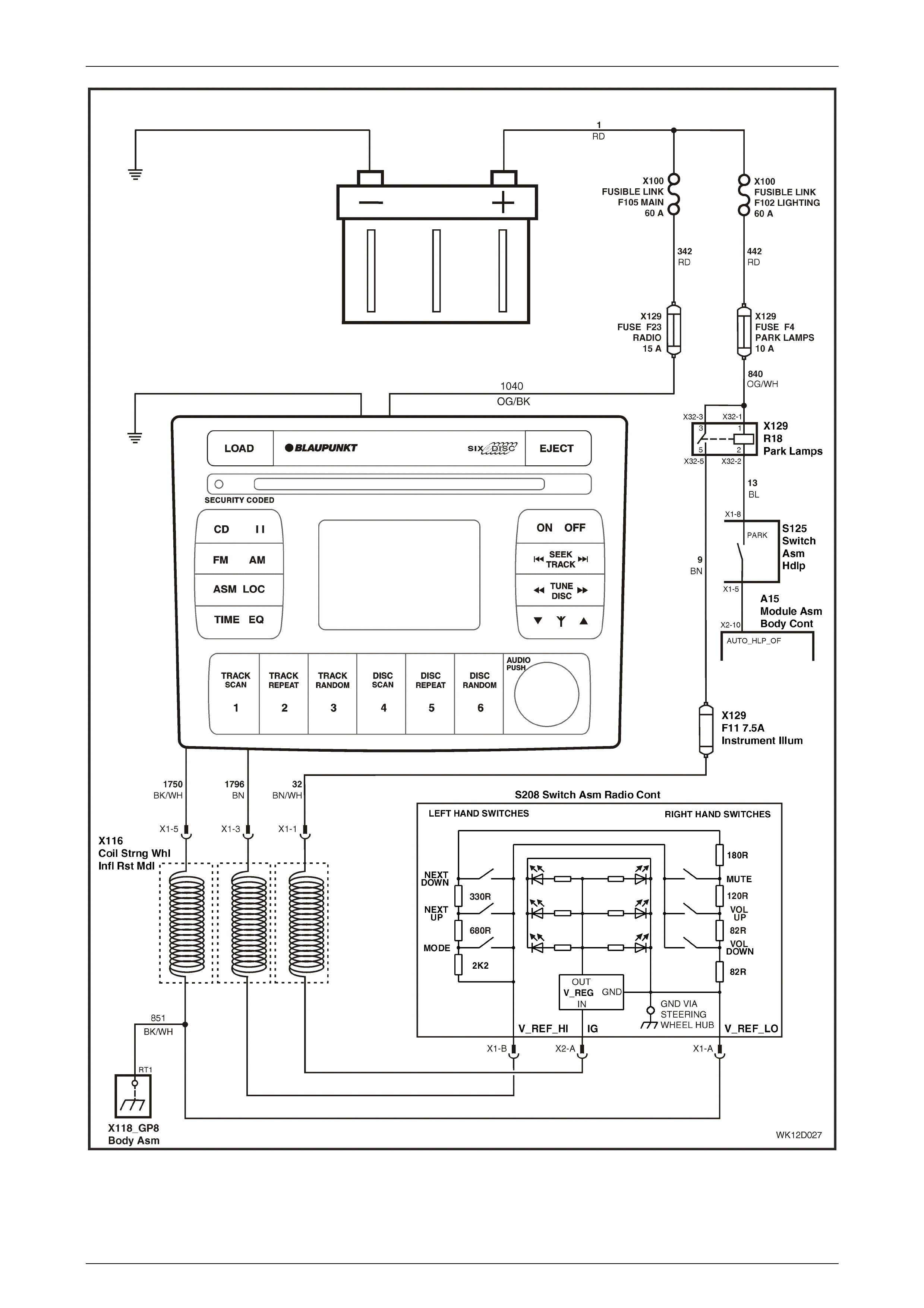
Entertainment System Page 12D–27
Page 12D–27
Figure 12D – 19
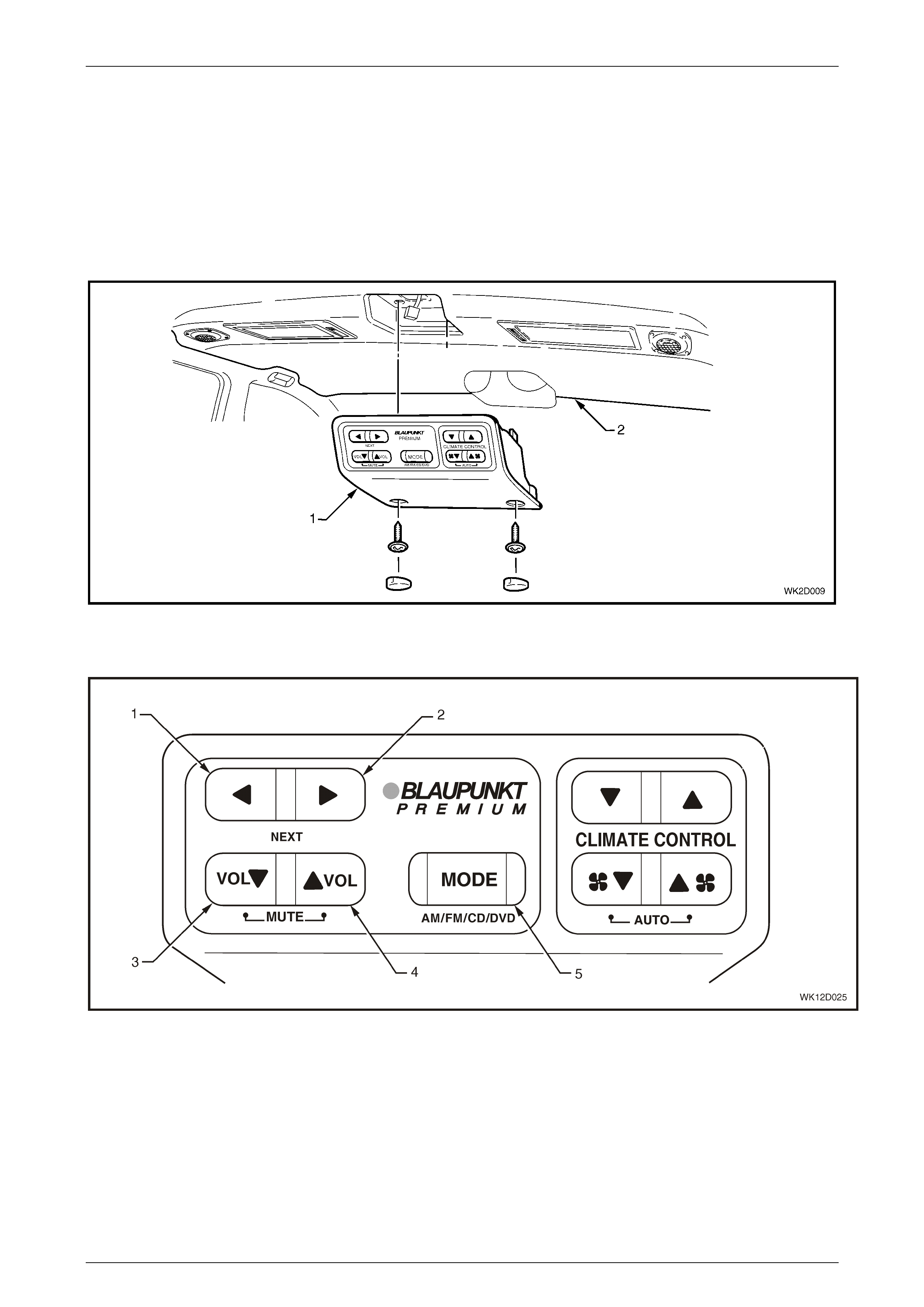
Entertainment System Page 12D–28
Page 12D–28
1.5 Rear Remote Control
On Level 5 MY 2004 WK Series vehicles, rear passengers can access a rear remote control (1), which is fitted to the
centre of the headlining (2) forward of the rear passenger compartment (refer to Figure 12D – 20).
The audio head unit contains a lock-out function for the rear remote controls to prevent rear seat passengers from
adjusting the audio system. The lockout function is activated and de-activated by pressing and holding the headphone
button on the audio head unit for more than 2 seconds. When the rear remote controls are locked, pressing a rear
remote control button will bring up a REAR REMOTE LOCKED message on the MFD. The rear remote control can select
DVD as the source but all other DVD functions are controlled through the hand held remote control.
Figure 12D – 20
Figure 12D – 21 illustrates the audio system functions available at the rear remote control unit.
Figure 12D – 21
Legend
1 Next Trac k / Station Bac k Switch 4 Volume Up Switch
2 Next Track / Station Forward Switch 5 Mode Switch – AM / FM Radio, CD Player or DVD Player
3 Volume Down Switch

Entertainment System Page 12D–29
Page 12D–29
1.6 Audio System Configuration
The following table details the audio system parameters that can be configured with TECH 2. This is achieved by
selecting the Code Index number for the appropriate vehicle model and audio system installed. Refer to 3.11 Program –
Audio System, F0: Program Code Index in this Section.
Parameter Setting
Tuner Frequency Range AUST, GCC (Gulf Countries), GMB (Brazil), EURO (Europe), GMTH (Thailand)
Clock Format Display 12 Hour / 24 Hour
Speed Dependent Volume
Curve 0, 1, 2, 3, 4, 5
0 = Off, 5 = Maximum Effect, 2 = Standard Setting
Maximum Switch On Volume 0 to 63
0 is an invalid setting, 63 = Feature Turned Off
Confirmation Beeps Radio and CD Changer Confirmation Beeps On, CD Changer Confirmation Beeps On,
or Off
LHD or RHD Left-hand Drive or Right-hand Drive Vehicle
Single or Dual Antenna Single = Main Antenna Only, Dual = Diversity Antenna (if fitted)

Entertainment System Page 12D–30
Page 12D–30
2 Service Operations
ATTENTION
All fasteners are important attaching parts as they affect the performance of vital components and / or could
result in major repair expense. Where specified in this section, fasteners MUST be replaced with parts of the
same part number or a GM approved equivalent. Do not use fasteners of an inferior quality or substitute
design.
Torque values must be used as specified during reassembly to ensure proper retention of all components.
Through out this section, fastener torque wrench specifications may be accompanied with the following
identification marks:
!
!!
! Fasteners must be replaced after loosening.
"
""
" Vehicle must be at kerb height before final tightening.
#
##
# Fasteners either have micro encapsulated sealant applied or incorporate a mechanical thread lock and
should only be re-used once. If in doubt, replacement is recommended.
If one of these identification marks is present alongside a fastener torque wrench specification, the
recommendation regarding that fastener must be adhered to.
2.1 Audio S ystem Head Unit
LT Section No. 09–440
Remove
It is recommended that the audio s ystem head
unit does not contain a CD when being
removed. Under some circumstances, a CD
may become dislodged if the unit is treated
roughly during removal.

Entertainment System Page 12D–31
Page 12D–31
1 Eject any CD’s that may be in the CD changer.
2 Ensure that the audio system is turned off.
3 Using the special service tools KM6067 (1), insert
the tools into the access holes and push the
service tool in to engage the barbs of the retaining
spring clips.
4 Apply outward pressure to the service tools to
release the spring clips then pull the audio head
unit out of the cradle.
5 Remove the service tools.
Figure 12D – 22
Reinstall
It is recommended that the audio s ystem head
unit does not contain a CD when being
installed. Under some circumstances, a CD
may become dislodged if the unit is treated
roughly during installation.
Installation is the reverse of the removal procedure noting the following points:
1 Service tools are not required to install the audio head unit.
2 Slide the audio head unit into the cradle then, using finger pressure over the removal tool holes, push the unit in
until the spring cli ps eng age.
Do not apply pressure to the buttons, knob or
display as damage may result.
3 If a new audio system head unit has been installed, enter the new security code. Refer to 2.19 Audio System
Security Code in this Section.
4 Store the new security code into BCM memory using TECH 2. Refer to Section 12J Body Control Module,
3.10 Security in the MY 2003 VY and V2 Series Service Information for further details. Ensure that the vehicle
owner is provided a copy of the new security code.
5 Check the audio system for correct operation. Load any customer CDs that were originally in the audio system.
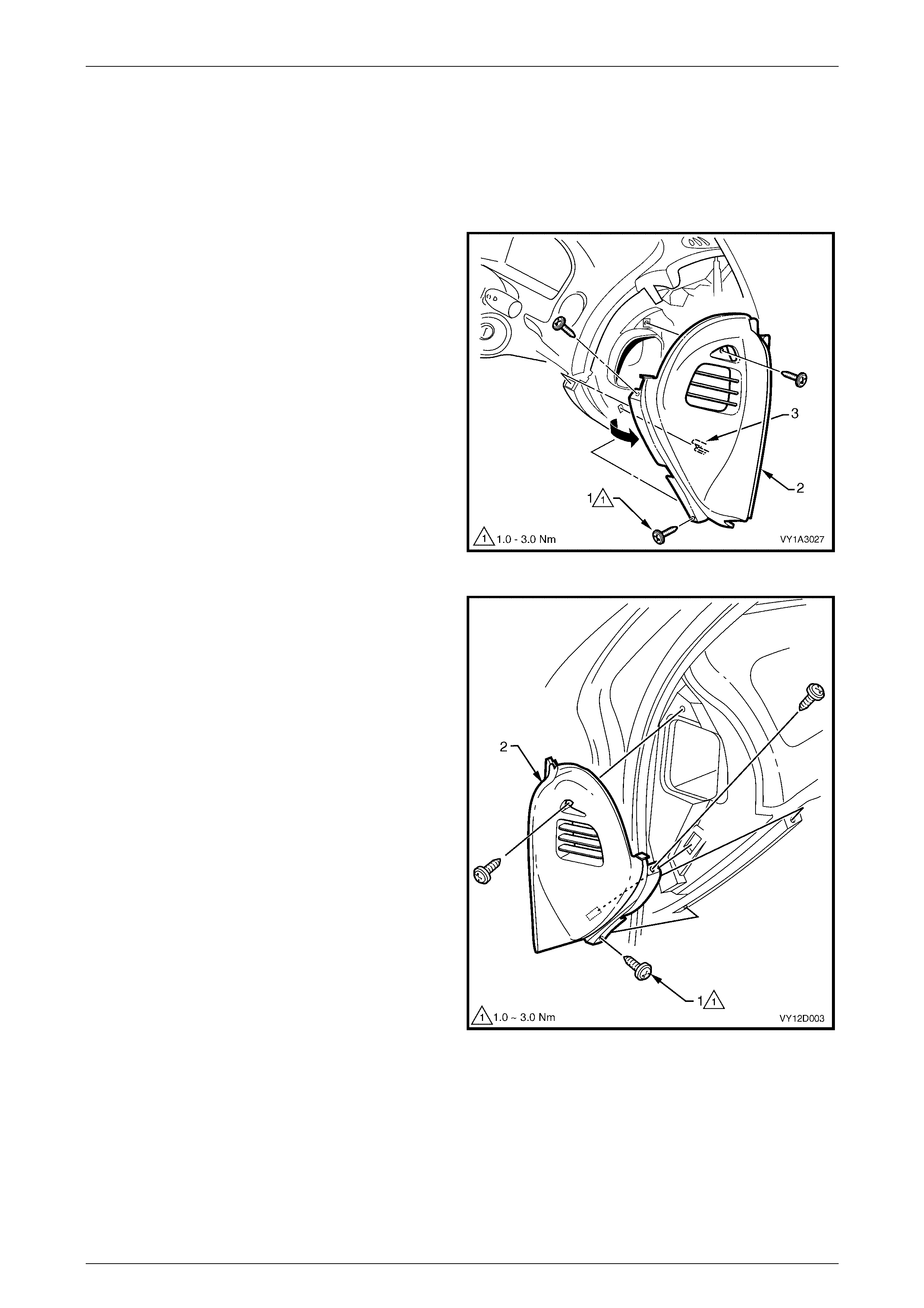
Entertainment System Page 12D–32
Page 12D–32
2.2 Instrument Panel Speakers – All Models
LT Section No. 09–500
Remove
1 Ensure that the audio system is turned off.
2 Remove the three screws (1) securing the right-hand
side instrument panel outer cover (2) and remove the
cover.
3 Remove the cover by rotating outward to disengage
the retaining clip (3) and the ventilation ducts.
Figure 12D – 23
4 Remove the three screws (1) securing the left-hand
side instrument panel outer cover (2) and remove the
cover.
Figure 12D – 24
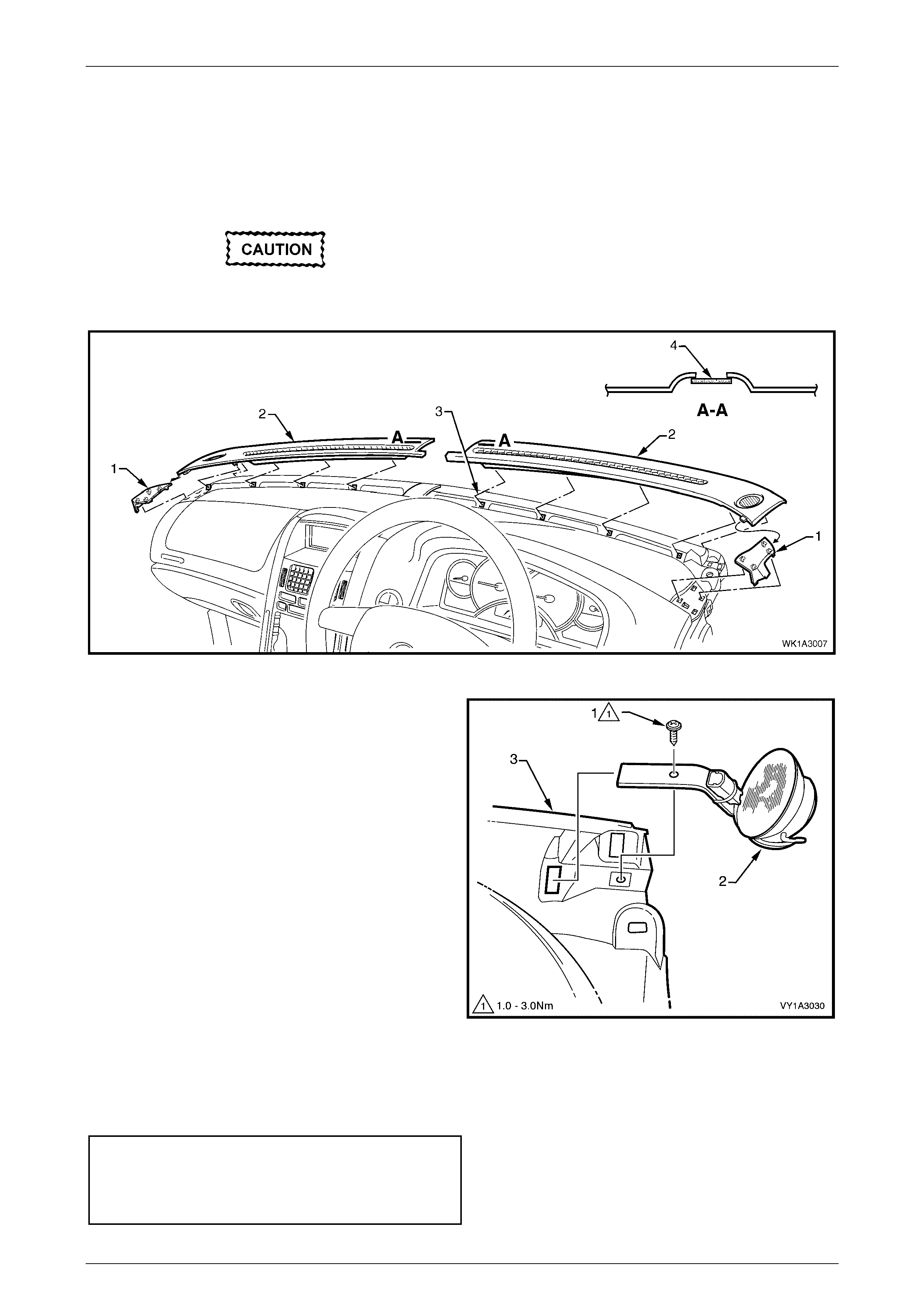
Entertainment System Page 12D–33
Page 12D–33
5 Remove the right-hand extension pad (1) from the
right-hand defroster grille (2) by unclipping in four
places, refer to Figure 12D – 25.
6 Carefully remove the grille (2) by unclipping (3), five
places, at an angle equal to the windshield.
7 Repeat steps 5 and 6 for the left-hand defroster grille.
On all vehicles, care must be taken to avoid
damage to the solar sensor (4).
Figure 12D – 25
8 Disconnect the harness connectors from the
speaker (2) on the left-hand and right-hand sides of
the instrument panel. Remove the screw (1) securing
each speaker to the instrument panel (3) then gently
pull the speakers outwards and then towards the rear
of the vehicle.
Figure 12D – 26
Reinstall
Installation is the reverse of the removal procedure. Tighten the retaining screws to the correct torque specification.
Instrument panel speaker retaining
screw torque specification.......................... 1.0 – 3.0 Nm
Instrument panel outer cover retaining
screw torque specification.......................... 1.0 – 3.0 Nm

Entertainment System Page 12D–34
Page 12D–34
2.3 Front Door Speakers – All Models
LT Section No. 09–500
Remove
1 Ensure that the audio system is turned off.
2 Remove the door trim from the front door. Refer to
Section 1A5, 2.1 Front Door Trim Panel Assembly in
this Service Information.
3 Remove the speaker assembly-to-speaker box
retaining screws (3).
4 Remove the speaker (2) from the speaker box (3).
5 Release the wiring harness (4) from the tab on the
rear of the speaker box.
6 Disconnect the wiring harness from the speaker
connector and remove the speaker.
Figure 12D – 27
Reinstall
Installation is the reverse of the removal procedure, noting
the following:
1 Ensure that the electrical connector (4) is properly
attached to the speaker.
2 Before installing the speak er, v isual ly inspec t the
cavity of the speaker mounting box (1) for protrusions
that will touch the underside of the speaker cone on
installation, i.e. cable ties etc. Secure the wiring
harness to the tab on the rear of the speaker box.
3 Carefully install the speaker retaining screws (3)
ensuring that the spe ak er frame is not distorte d w hen
the screws are tightened.
Angled insertion of the speaker retaining
screws can lead to speaker distortion. Make
sure that the screws are installed square to
the speaker frame.
Front door speaker retaining
screw torque specification.......................... 1.0 – 3.0 Nm

Entertainment System Page 12D–35
Page 12D–35
NOTE
There are specific front speaker assemblies for
the various vehicle models. Figure 12D – 26
illustrates the underside view of a speaker
showing the location of the identification details,
eg Part Number (1) and the speaker
impedance (2).
Check that the part numbers and resistance values are
correct, as incorrect speaker fitment can affect system
operation, resulting in unnecessary complaints.
Check speaker operation once installation has been
completed.
Figure 12D – 28
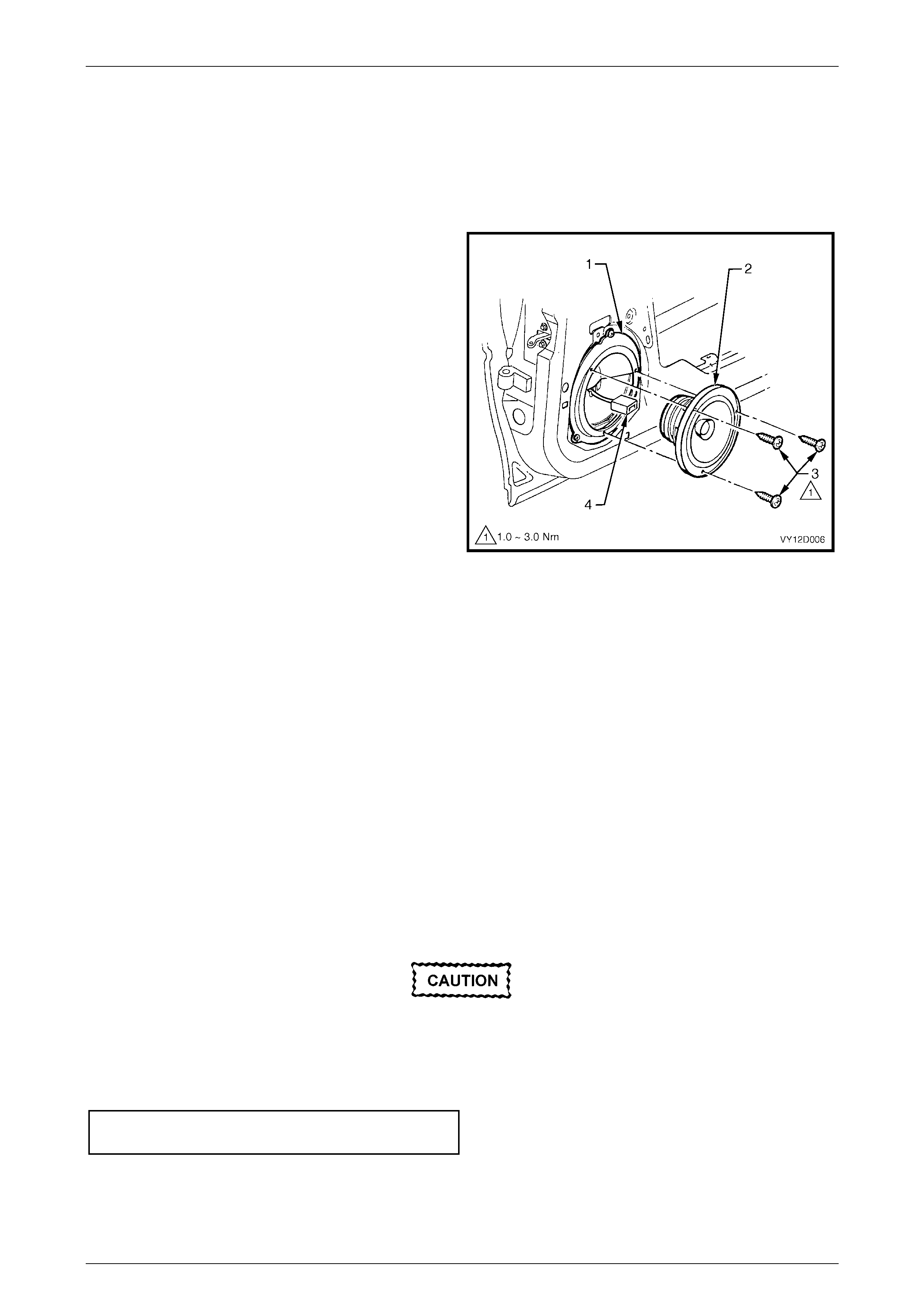
Entertainment System Page 12D–36
Page 12D–36
2.4 Rear Door Speakers
LT Section No. 09–500
Remove
1 Ensure that the audio system is turned off.
2 Remove the door trim from the rear door, refer to
Section 1A5, 2.3 Rear Door Trim Panel Assembly in
this Service Information.
3 Remove speaker assembly to speaker box retaining
screws (3).
4 Remove the speaker (2) from speaker box (1).
5 Release the wiring harness (4) from the tab on the
rear of the speaker box.
6 Disconnect the wiring harness from the speaker
connector and remove the speaker.
Figure 12D – 29
Reinstall
Installation is the reverse of the removal procedure, noting the following points:
NOTE
There are specific rear speaker assemblies
for the various vehicle models. Refer to
Figure 12D – 28 for identification details. Check
that the part numbers and resistance values are
correct, as incorrect speaker fitment can affect
system operation.
1 Ensure that the electrical connector (4) is properly attached to the speaker.
2 Before installing the speaker (2), visually inspect the cavity of the speaker mounting box (1) for protrusions that will
touch the underside of the speaker cone on installation, i.e. cable ties etc. Secure the wiring harness to the tab on
the rear of the speaker box.
3 Carefully install the speaker retaining screws (3) ensuring that the speaker frame is not distorted when the screws
are tightened.
Angled insertion of speaker retaining screws
can lead to speaker distortion. Make sure
screws are installed square to speaker frame
and are tightened to the correct torque
specification.
Rear door speaker retaining
screw torque specification.......................... 1.0 – 3.0 Nm
4 Check the speaker operation once installation has been completed.
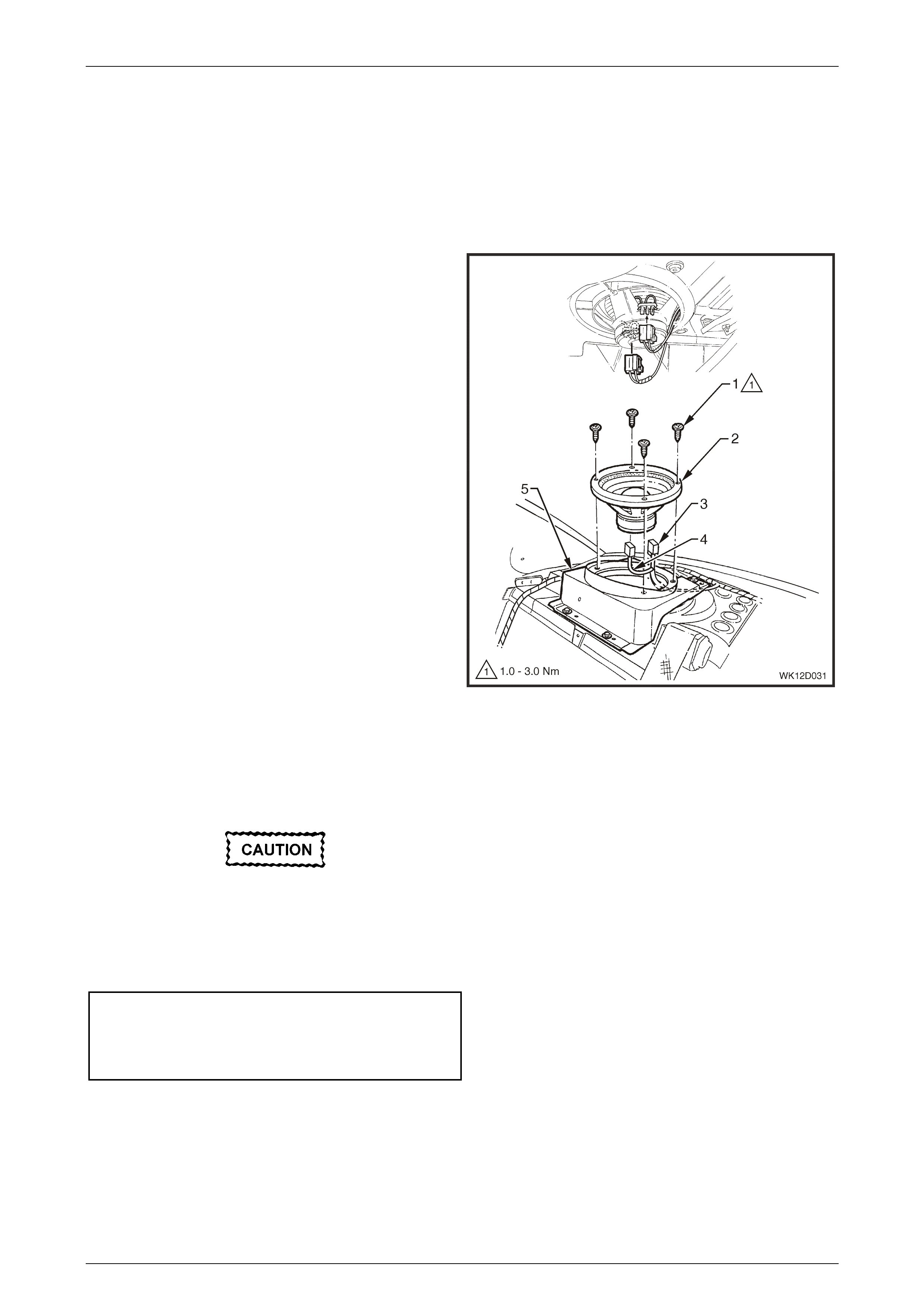
Entertainment System Page 12D–37
Page 12D–37
2.5 Subwoofer Speakers – Level 4 and 5
Vehicles
LT Section No. 09–500
Remove
1 Ensure that the audio system is turned off.
2 Remove rear window trim panel assembly. Refer to
Section 1A8, 2.5 Rear Window Trim Panel Assembly
in this Service Information.
3 From inside the rear compartment, careful ly remov e
the connection (3) or connections (3) and (4) (Level 5
vehicles only) from the left-hand and right-hand side
subwoofers.
4 From within passenger compartment, remove the four
screws (1) securing each subwoofer (2) and carefully
lift the subwoofer from the mounting bracket (5).
Reinstall
Installation is the reverse of the removal procedure, noting
the following:
1 Ensure that the electrical connectors are properly
attached to the speakers.
2 Before installing the speak ers, visually inspect the
speaker mounting box cavities for protrusions that will
touch the underside of the speaker cone on
installation, i.e. cable ties etc.
3 Carefully install the speaker retaining screws, ensuring
that the speaker frames are not distorted when the
screws are tightened. Ensure that the wiring harness
(6) is not jammed.
4 Install rear window trim panel assembly, refer to
Section 1A8, 2.5 Rear Window Trim Panel Assembly
in this Service Information.
Angled insertion of speaker retaining screws
can lead to speaker distortion. Make sure
screws are installed square to speaker frame.
5 Ensure child seat anchor screw is tightened to the
correct torque specification.
Subwoofer speaker retaining
screw torque specification.......................... 1.0 – 3.0 Nm
Child seat anchor atta chi ng sc rew
torque specification ................................ 15.0 – 25.0 Nm
Figure 12D – 30

Entertainment System Page 12D–38
Page 12D–38
2.6 Roof Mounted Speakers – Level 5
LT Section No. 09–500
Remove
1 Remove the four attaching screws (3) from the
speaker assem bly .
2 Carefully remove speaker (2) from roof console to
avoid damaging the insulating boots covering the
terminals.
3 Disconnect wiring harness connector (1) from speaker
and remove speaker.
Reinstall
Installation is the reverse of the removal procedure noting
the following:
1 Ensure electrical connector is properly attached to
speaker.
2 Before installing speak er, vis u ally inspe ct spea ker
mounting cavity for protrusions that will touch the
underside of the speaker cone on installation and
rectify.
3 Ensure that the insulating boots are correctly installed
over the terminals at the speaker and are not
damaged. Replace the insulating boots if necessary.
Angled insertion of speaker attaching screws
can lead to speaker distortion. Make sure that
screws are installed square to the speaker
frame.
4 Carefully install speaker attaching screws ensuring
that speaker frame is not distorted when screws are
tightened to the specified torque.
Roof mounted speaker attaching
screws torque specification ....................... 1.0 – 3.0 Nm.
Figure 12D – 31
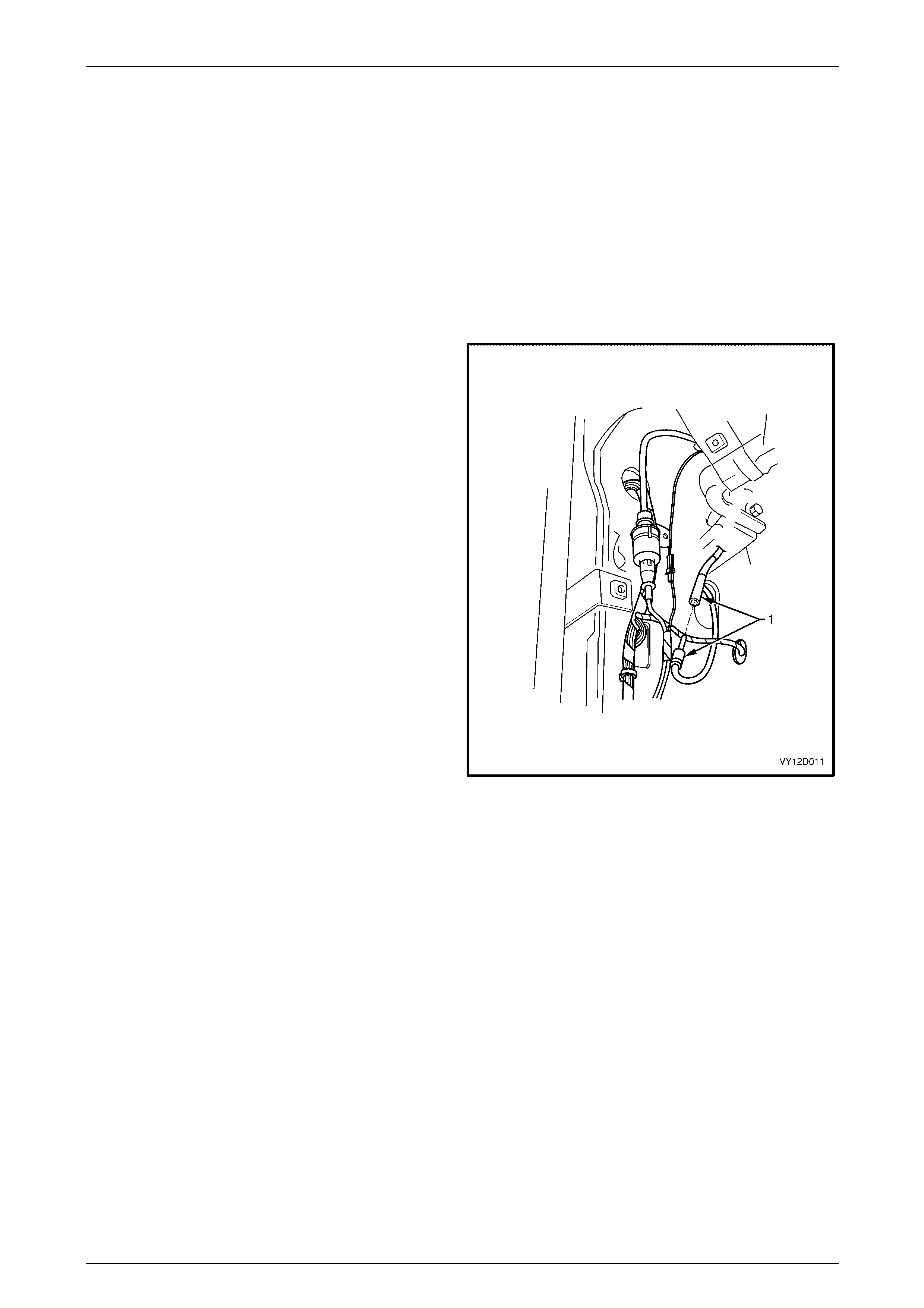
Entertainment System Page 12D–39
Page 12D–39
2.7 Power Antenna
Power Antenna Switches
The power antenna directional control switches are integrated with the AHU and as such cannot be serviced separately.
Power Antenna Assembly
LT Section No. 09–400
Remove
1 Ensure that the audio system is turned off and that the
antenna mast is in the fully retracted position.
2 From inside the vehicle, remove the appropriate side
hinge pillar trim assembly. Refer to Section 1A8,
2.8 Hinge Pillar Trim Assembly in the MY 2003 VY and
V2 Series Service Information. For RHD vehicles,
remove the left-hand side assembly, for LHD vehicles
remove the right-hand side assembly.
3 For RHD models, leave the wiring harnesses
connected to the exposed Powertrain Control Module
(V6 models) or the Powertrain Interface Module
(GEN III V8 models) and manoeuvre the module from
the plastic mounting bracket.
4 Remove the plastic mounting bracket. Refer to
Section 6C1–3 Powertrain Control Module in the
MY 2003 VY and V2 Series Service Information.
5 For all models disconnect the antenna lead (1) from
the connecting socket of the antenna extension lead.
NOTE
Figure 12D – 32 illustrates a RHD vehicle
installation. For LHD vehicles, installation is
similar but on the opposite side.
Figure 12D – 32
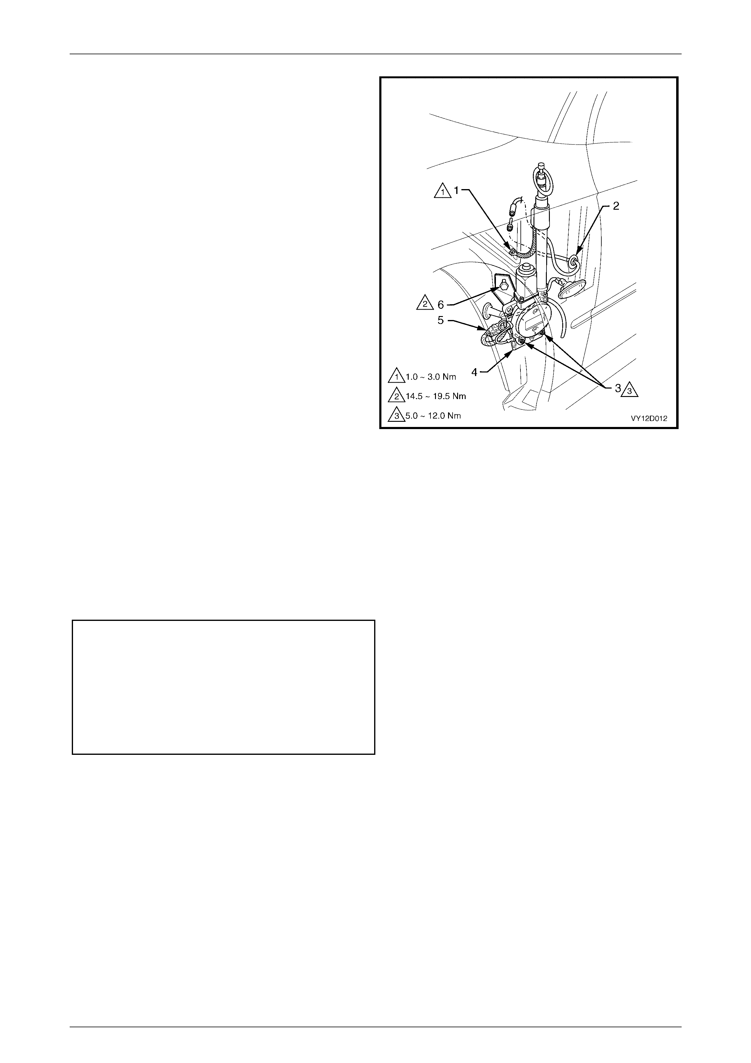
Entertainment System Page 12D–40
Page 12D–40
NOTE
Figure 12D – 33 illustrates a RHD antenna
assembly installation. For LHD vehicles,
installation is mounted on the opposite side of
the vehicle, and installation is the same.
6 Remove the appropriate fender inner liner. Refer to
Section 1A1, 3.1 Front Wheelhouse Liner in the
MY 2003 VY and V2 Series Service Information.
7 Remove the screw (1) connecting the ground braid to
the inner fender ground terminal.
8 Disconnect the antenna wiring harness connector (5)
from the main wiring harness connector in the wheel
well.
9 While support ing the ante nna ass emb ly (4), remove
the retaining bolt (6) from the antenna support bracket.
10 Remove the antenna lead grommet (2) from the inner
fender panel and pull the lead out from the passenger
compartment.
11 Withdraw the antenna down through the bezel and
remove the antenna, complete with leads, grommet
and bracket.
12 Remove the two nuts (3) securing the antenna to the
mounting bracket.
Figure 12D – 33
Reinstall
Installation of the power antenna is the reverse of the removal procedure, taking note of the following:
1 Ensure that the cable and harness are rout ed correctly .
2 Ensure that the antenna and the ground leads are routed correctly and are securely connected.
3 With the antenna pushed up against the stop in the bezel, tighten the bolt attaching the antenna bracket to the
inner fender panel to the correct torque specification.
Antenna bracket to inner fender
panel retaining bolt
torque specification ................................ 14.5 – 19.5 Nm
Antenna ground braid to inner fender
panel retaining screw
torque specific atio n .................................... 1.0 – 3.0 Nm
Antenna assembly to bracket nuts
torque specific atio n .................................. 5.0 – 12.0 Nm
4 Check the antenna operation and the radio reception.

Entertainment System Page 12D–41
Page 12D–41
Mast Replacement
LT Section No. 09–400
The following procedure is for replacing a damaged or faulty antenna mast and drive cable assembly.
1 Remove the power antenna assembly as previously described in this Section.
2 Remove the chrome-plated nu t from the top end of the mast tube.
3 Extend the damaged antenna mast as far as possible by attaching the battery negative, via a jumper lead, to the
antenna mounting bracket and connect the battery positive to both the antenna red and white wire terminals.
4 At the end of the mast travel, pull out the mast and drive cable from the antenna housing.
NOTE
If the mast is too badly damaged to extend, grip
the tip of mast with a pair of pliers and pull the
mast and drive cable assembly up and out from
the antenna housing.
5 If necessary, remove the contact spring (metal sleeve) from the old mast and drive cable and install onto the
replacement mast and drive cable.
6 Feed the end of the drive cable down the mast tube of the antenna housing with the serrated side of the drive cable
facing toward the centre of the housing. Continue to feed the drive cable down until it engages with the drive
mechanism.
NOTE
It may be necessary to twist the drive cable
clockwise and anti-clockwise slightly to enable
the end of cable to feed through the opening at
the base of the mast tube before it engages the
drive mechanism.
7 With an assistant holding the antenna and mast assembly, connect the antenna support bracket, via a jumper lead,
to battery negative.
8 Momentarily connect battery positive to the antenna red wire. The drive mechanism should start to retract the drive
cable into the antenna housing.
9 With the drive cable engaged to the drive mechanism, reconnect battery positive to the antenna red wire and allow
the drive mechanism to wind in the drive cable and mast into the mast tube and housing.
10 At this stage the mast might be fully retracted into the mast tube and housing. Reconnect both the red and white
wires to battery positive and allow the mast to extend fully until the motor stops.
11 Disconnect the white wire from battery positive and allow the mast to fully retract.
12 Install the chrome-plated nut onto the mast tube and tighten the nut securely.
13 Install the power antenna assembly as described previously in this Section then check the antenna mast operation
and radio reception.
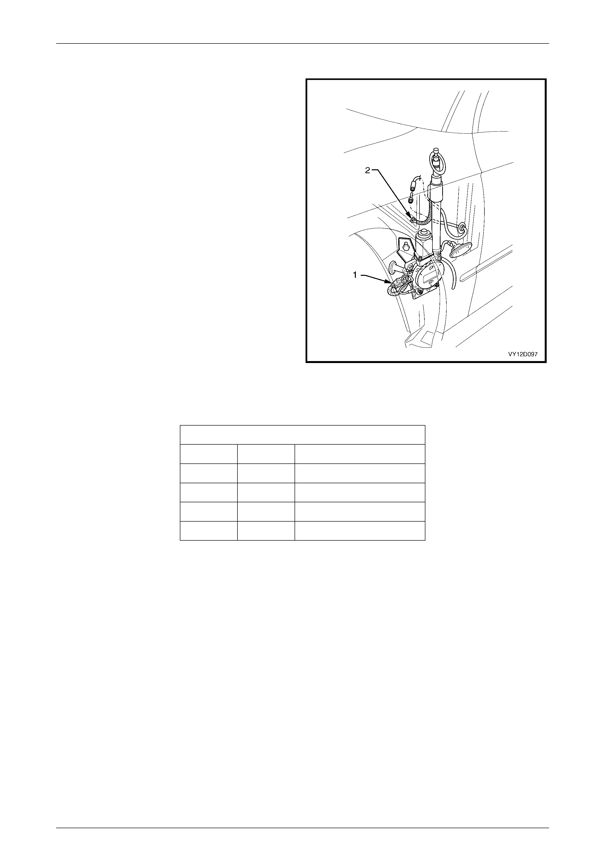
Entertainment System Page 12D–42
Page 12D–42
Checking Antenna Motor Operation
NOTE
The following ‘Checking Antenna Motor
Operation’ tests are made at the main wiring
harness-to-antenna motor connector located in
the wheel well. It will be necessary to remove the
front wheel liner to gain access to the connector.
Refer to Section 1A1, 3.1 Front Wheelhouse
Liner in the MY 2003 VY and V2 Series Service
Information.
Legend
1 Main wiring harness-to-ant enna mot or connector
2 Ground braid
Figure 12D – 34
The voltages shown are measured to a good ground point on the vehicle body.
Voltage on Antenna Harness Wires
Red White Action
12 V 12 V Antenna extends
12 V 0 V Antenna retracts
0 V 12 V Antenna does not move
0 V 0 V Antenna does not move
If the antenna motor does not correctly respon d to the inputs as specif ied, ens ure that a good ground con nec tio n is being
made through the mounting bracket by measuring the resistance from the bracket to a good ground point. If more than
1 ohm is recorded, remove the antenna assembly as described in this Section. Ensure that the bracket and body contact
surfaces are clean. If all OK, replace the power antenna assembly. Check that the black wire with the forked ground
connector (item 3 in Figure 12D – 34) is securely attached to the antenna mounting bracket.
NOTE
If there is significant noise on the AM band (with the
radio tuned to a weak station outdoors), then check
the ground quality of the antenna at the points
previously mentioned. The antenna ground terminal
has a large effect on the screen in Level 1 vehicles.
Also check the ground quality of the ground braid.
Refer to Item 2 of Figure 12D – 34).

Entertainment System Page 12D–43
Page 12D–43
2.8 Diversity Antenna
The diversity antenna is an integral part of the rear window assembly. The thin conductors that form the diversity antenna
are laid on the inside of the rear window glass in the same manner as the rear window heating elements.
A single terminal is located on the inside of the rear window glass, on the passenger side, to allow connection of the
diversity antenna to the diversity antenna module, located under the rear parcel shelf trim.
The diversity antenna module amplifies the radio signal received by the diversity antenna and transmits it to the audio
system head unit via coaxial cable.
NOTE
Due to the internal circuitry of the radio receiver,
if the fender mounted mast antenna is retracted,
faulty or disconnected, the radio may not use the
diversity antenna system for radio reception if the
FM signal is weak.
Diversity Antenna – Test
1 Remove the body lock pillar garnish (rear quarter window trim) from the left-hand side of the vehicle. Refer to
Section 1A8, 2.4 Body Lock Pillar Garnish in this Service Information.
2 Disconnect the diversity antenna module connector from the diversity antenna terminal.
3 Using an ohmmeter measure the resistance from the diversity antenna terminal to the diversity antenna conductors
on the inside of the rear window glass. Resistance should be less than 20 ohms from the diversity antenna
connector to any point on the diversity antenna conductors.
Avoid using excessive force on the ohmmeter
probe, as damage to the diversity antenna
conductors will result.
Diversity Antenna Module
LT Section No. 09–400
Remove
1 Ensure that the audio system is turned off.
2 Remove the rear window trim panel assembly. Refer to Section 1A8, 2.5 Rear Window Trim Panel Assembly in this
Service Information.
3 Remove the left-hand side sill trim and plate assembly. Refer to Section 1A8, 2.2 Side Sill Trim and Plate in this
Service Information.
4 Remove the left-hand side body lock pillar lower trim. Refer to Section 1A8, 2.3 Body Lock Pillar Lower Trim in this
Service Information.
5 Remove the left-hand side hinge pillar trim assembly. Refer to Section 1A8, 2.8 Hinge Pillar Trim Assembly in the
MY 2003 VY and V2 Series Service Information.

Entertainment System Page 12D–44
Page 12D–44
6 Leaving the Powertrain Control Module (V6 models) or
the Powertrain Interface Module (GENIII V8 models)
wiring harnesses connected to the exposed module,
manoeuvre the module from the plastic mounting
bracket.
7 Remove the plastic mounting bracket. Refer to
Section 6C1-3, 2.1 Powertrain Control Module in the
MY 2003 VY and V2 Service Information.
8 Disconnect the diversity antenna module coaxial
cable (1) from the radio diversity antenna extension
cable connector.
9 Disconnect the diversity antenna module power
cable (2) to main wiring harness connector.
10 Remove the diversity antenna module leads from the
retaining clips and remove the leads from the rocker
panel.
Figure 12D – 35
11 Remove the screw (1) securing the diversity antenna
amplifier (4) to the rear parcel shelf. Remove the
diversity anten na modu le and l eads .
12 Remove the screw (2) securing the diversity antenna
ground terminal to the vehicle body.
13 Remove the diversity antenna module connector (3)
from the diversity antenna terminal located on the rear
window.
Figure 12D – 36
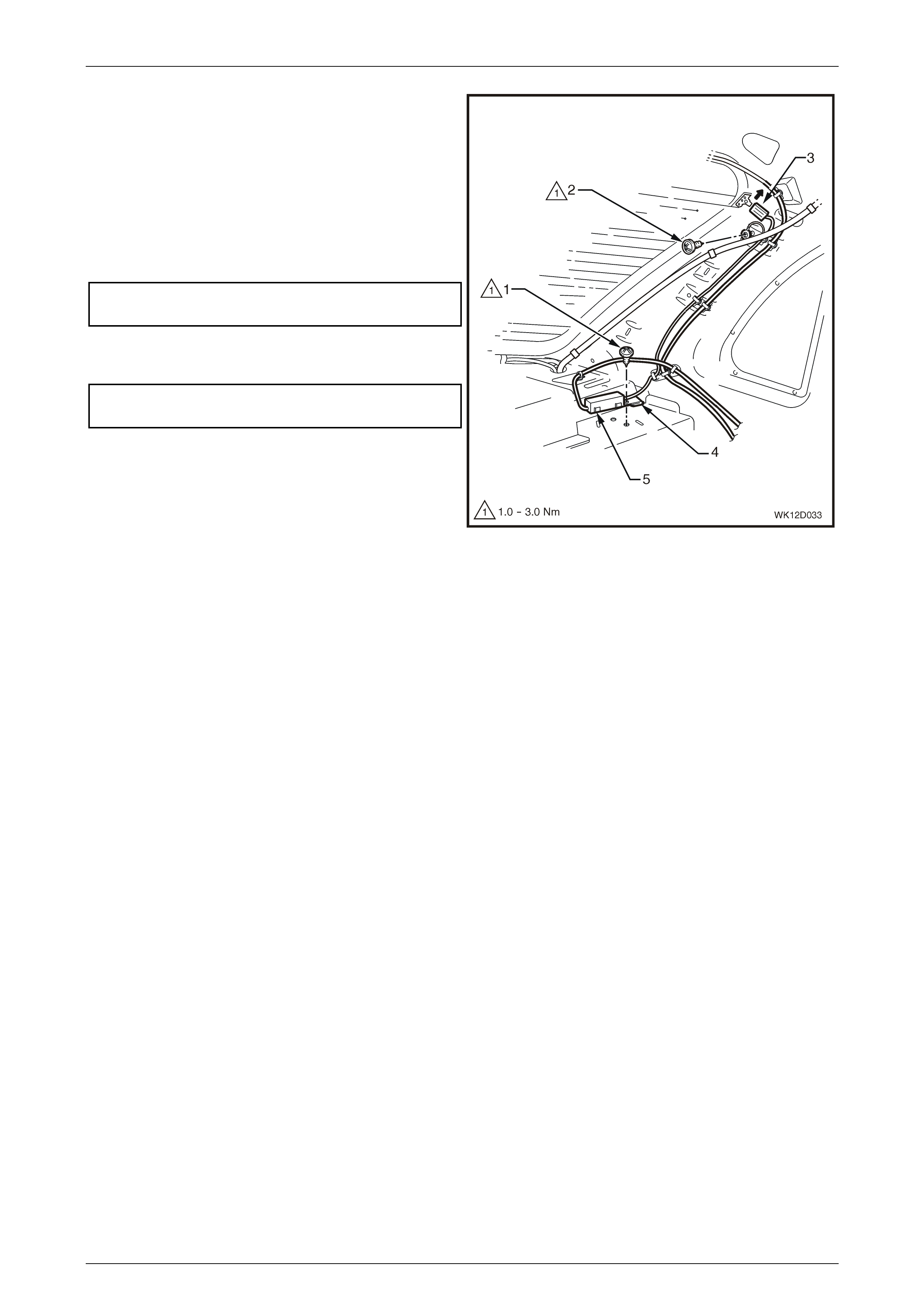
Entertainment System Page 12D–45
Page 12D–45
Reinstall
Installation of the diversity antenna module is the reverse of
the removal procedure, noting the following:
1 Ensure that the mounting tab (4) on the diversity
antenna module (5) is correctly engaged into the
mounting slot on the rear parcel shelf.
2 Tighten the diversity antenna module mounting
screw (1) to the correct torque specification.
Diversity antenna module mounting
screw torque specification.......................... 1.0 – 3.0 Nm
3 Tighten the diversity antenna grounding screw (2) to
the correct torque specification.
Diversity antenna grounding
screw torque specification.......................... 1.0 – 3.0 Nm
4 After installing the diversity antenna connector (3),
bend the tab in the direction shown.
Figure 12D – 37

Entertainment System Page 12D–46
Page 12D–46
2.9 Horn Bar Stereo Controls
The horn bar stereo control system consists of two control switch assemblies, one located on each side of the driver’s
side airbag (horn bar).
The horn bar stereo controls utilise the clock spring coil harness as a data link to the radio.
LT Section No. 09–440
Remove
Disable the OPS, SRS. Refer to Section 12M,
2.2 System Disabling and Enabling Procedure
in the MY 2003 VY and V2 Series Service
Information.
1 Ensure that the audio system is turned off.
2 Remove the airbag assembly from the steering wheel. Refer to Section 12M, 2.3 S teering Wheel In flatable
Restraint Module Assembly in the MY 2003 VY and V2 Series Service Information.
Figure 12D – 38
3 Disconnect the left-hand and right-hand horn bar stereo control harness (1) from the clockspring connector.
4 Remove the steering wheel assembly. Refer to Section 9, 2.4 Steering Wheel Assembly in the MY 2003 VY and V2
Series Service Information.
5 Remove the two screws (2) securing the steering wheel back shroud (3) to the steering wheel. Remove the back
shroud.
6 Disconnect the steering wheel switch harness (4) from the steering wheel earth tab (5).
Techline
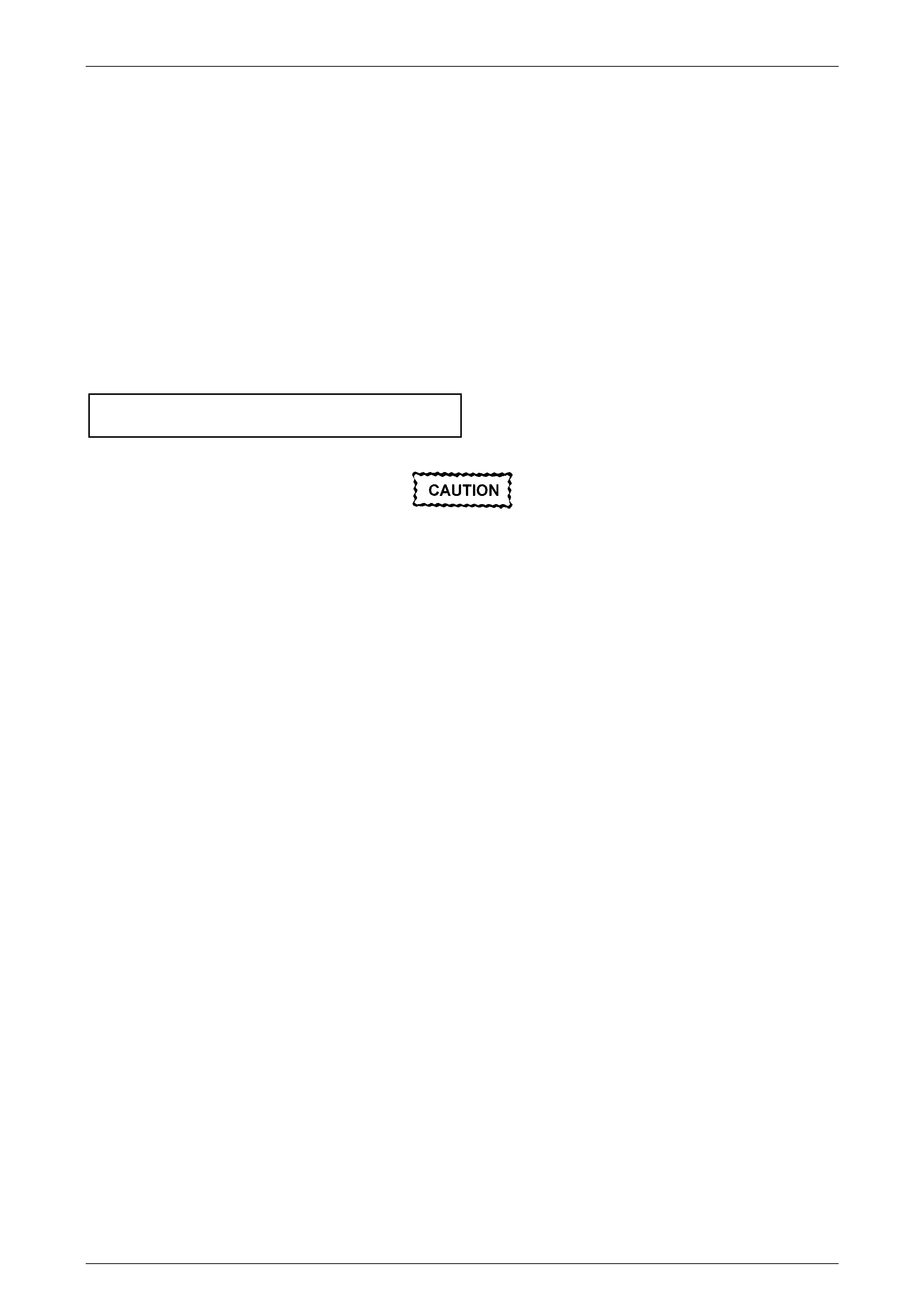
Entertainment System Page 12D–47
Page 12D–47
7 Remove the four screws (6) attaching the horn bar stereo switch assemblies (7) to the steering wheel and remove
the horn bar stereo switch assemblies.
NOTE
The horn bar stereo switch assembly consists of
two switch blocks connected together by a wiring
harness.
Reinstall
Installation of the horn bar stereo control system is the reverse of the removal procedure, noting the following:
1 Ensure that the stereo switch connectors seat correctly into the retaining clips on the steering wheel to avoid
crushing when the airbag is installed.
2 Tighten screws attaching the horn bar stereo switch assemblies to the steering wheel to the correct torque
specification.
Stereo switch assembly to steering wheel
screw torque specification.......................... 1.0 – 3.0 Nm
Enable the OPS, SRS. Refer to Section 12M,
2.2 System Disabling and Enabling Procedure
in the MY 2003 VY and V2 Series Service
Information.
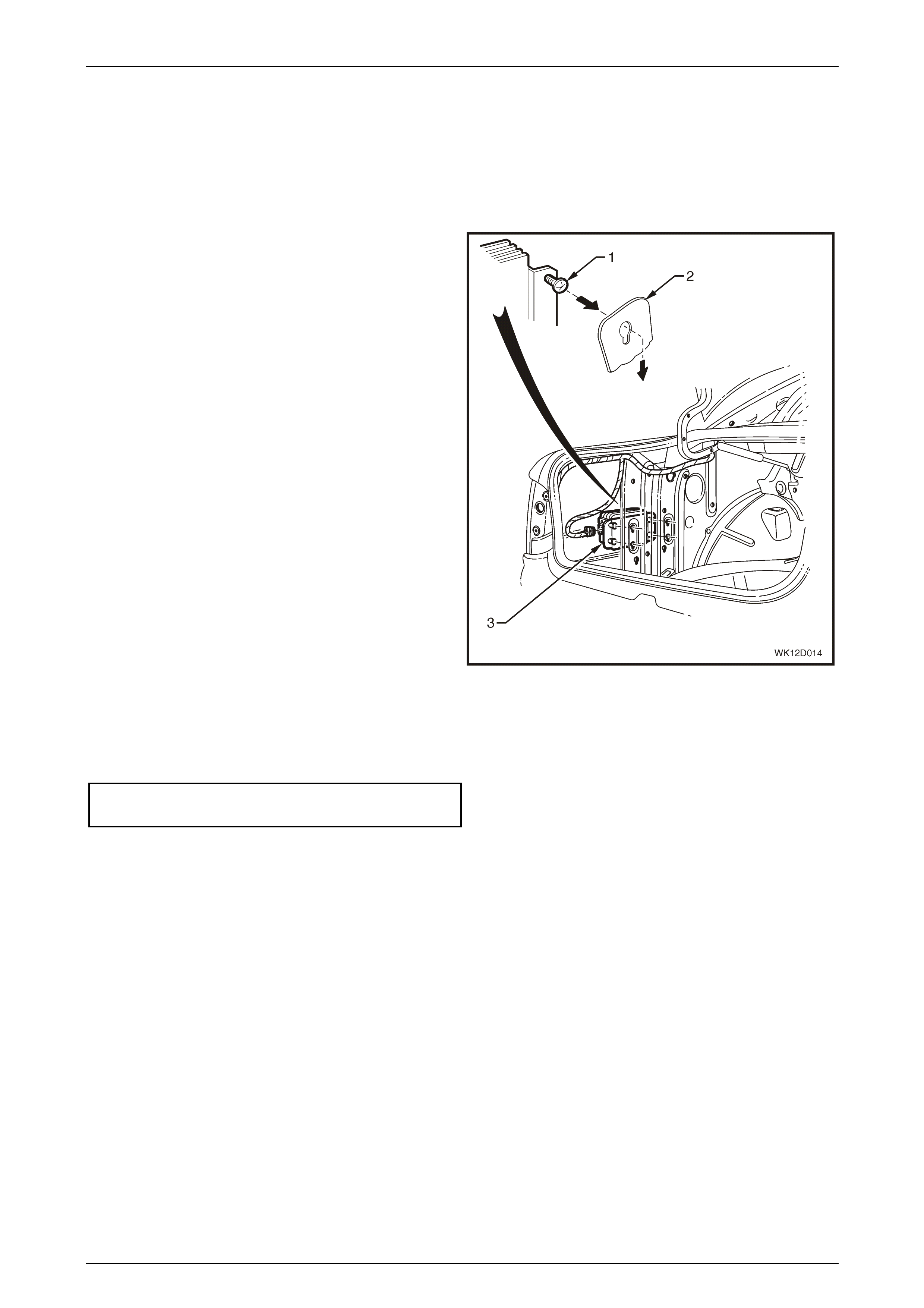
Entertainment System Page 12D–48
Page 12D–48
2.10 Subwoofer Amplifier
LT Section No. 09–515
Remove
1 Ensure that the audio system is turned off.
2 Open the rear compartment and remove the left hand
side quarter inner rear side carpet. Refer to
Section 1A8, 2.7 Quarter Inner Rear Side Carpet in
this Service Information.
3 Loosen the four subwoofer amplifier retaining screws
(1) and slide the amplifier upward to release the screw
heads from the slots in the inner side panel (2).
4 Withdraw the subwoofer amplifier assembly (3) from
the rear compartment.
5 Disconnect the side subwoofer amplifier assembly
harness connec tor.
Figure 12D – 39
Reinstall
Installation is the reverse of the removal procedure. Tighten the retaining screws to the correct torque specification.
Subwoofer amplifier retaining
Screw torque specification.......................... 0.5 – 1.5 Nm
Check the operatio n of the subwoofer amplifier.
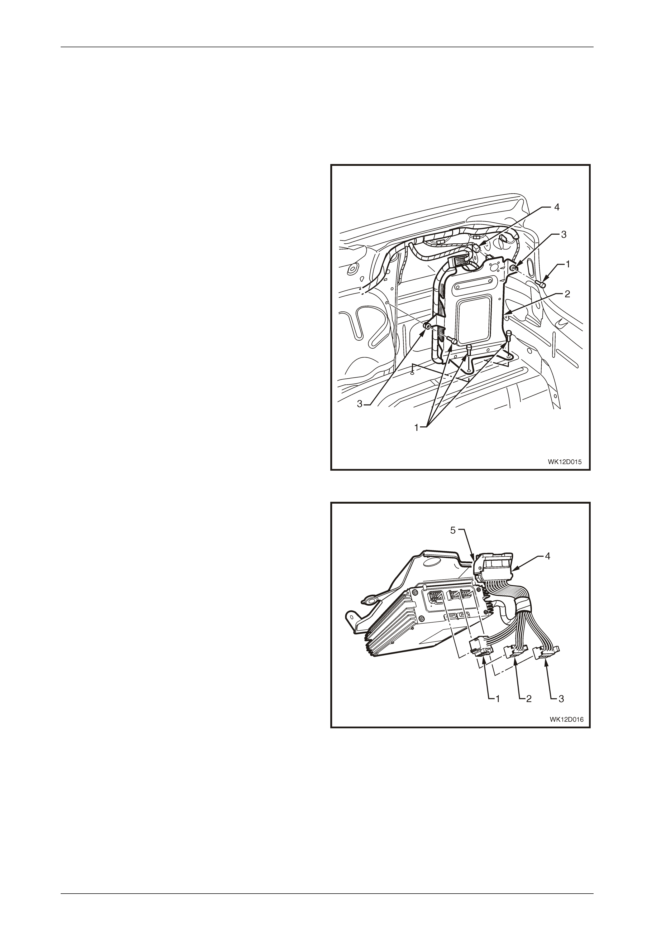
Entertainment System Page 12D–49
Page 12D–49
2.11 Premium Sound Amplifier
LT Section No. 09–515
Remove
1 Ensure that the audio system is turned off.
2 Open the rear compartment and remove the left hand
side quarter inner rear side carpet. Refer to
Section 1A8, 2.7 Quarter Inner Rear Side Carpet in
this Service Information.
3 Remove the four screws (1) attaching the premium
sound amplifier mounting bracket (2) to the side and
floor panels. Ensure that the two rubber insulators (3)
remain in place on the mounting bracket.
Figure 12D – 40
4 Pull the lever (5) on the body wiring harness connector
(4) backwards to release the connector.
5 Withdraw the premium sound amplifier mounting
bracket from the rear compartment.
6 Disconnect the premium sound amplifier harness
connectors N7-X3 (1), N7-X2 (2), N7-X4 (3).
Figure 12D – 41

Entertainment System Page 12D–50
Page 12D–50
7 Disconnect the four harness retaining clips (1) from
the mounting bracket (2) and disconnect the premium
sound amplifier harness connector N7-X1 (3).
Figure 12D – 42
8 Remove the four screws (1), nylon bush es (2) and
washers (3) attaching the premium sound amplifier (4)
to the mounting bracket (5) and remove the premium
sound amplifier.
Figure 12D – 43
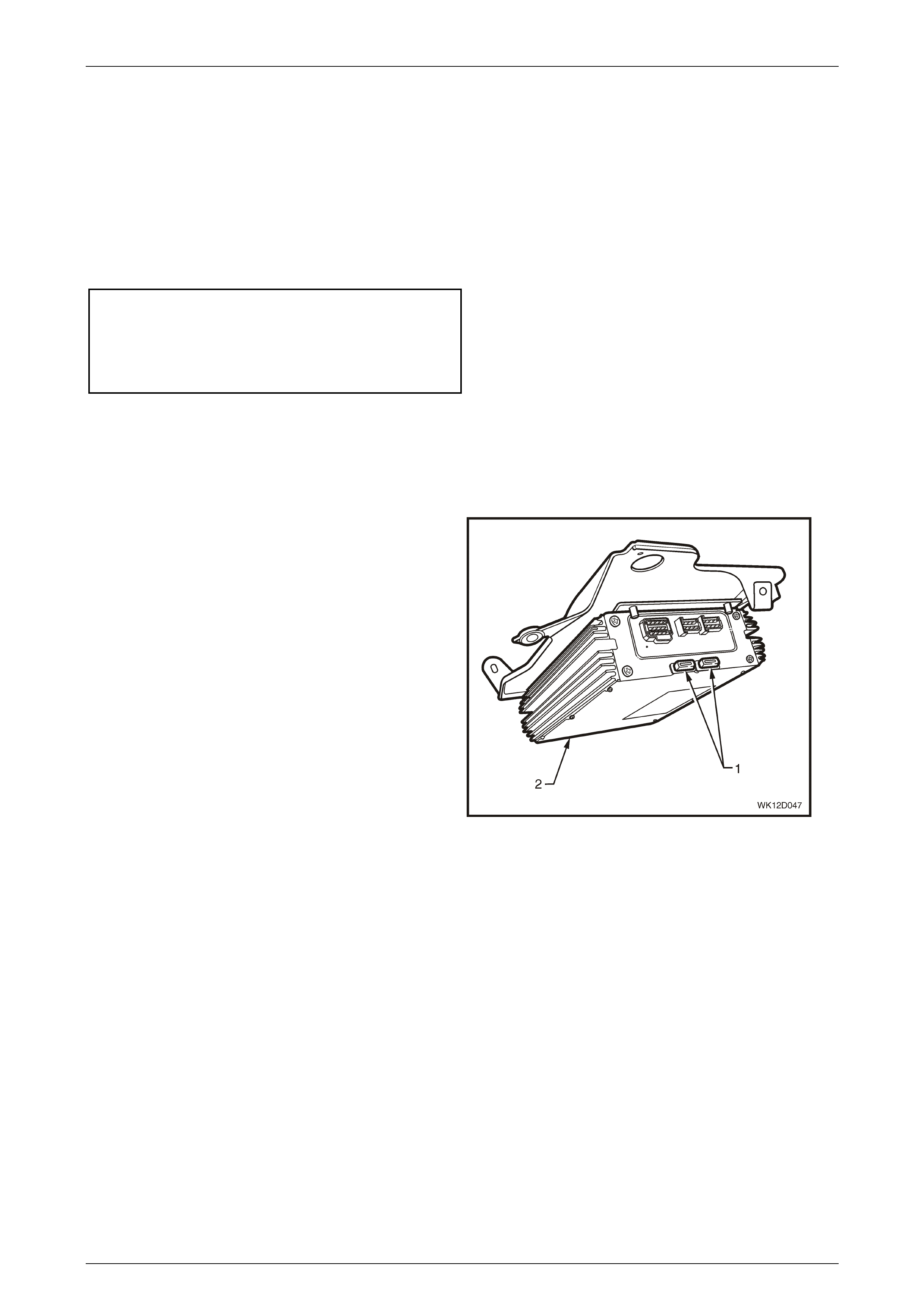
Entertainment System Page 12D–51
Page 12D–51
Reinstall
NOTE
Ensure that the rubber insulators are correctly
positioned with each side of the premium sound
amplifier mounting bracket. Incorrect placement
of the insulators may result in interference with
the premium sound amplifier.
Installation is the reverse of the removal procedure. Tighten the retaining screws to the correct torque specification.
Premium sound amplifier mounting
bracket attaching screw
torque specific atio n .................................... 2.0 – 4.0 Nm
Premium sound amplifier attaching
screw torque specification...................................0.9 Nm
Check the operatio n of the premiu m sound ampli fier.
PSA Fuses
Remove
1 Ensure that the audio system is turned off.
2 Open the rear compartment and remove the left hand
side quarter inner rear side carpet. Refer to
Section 1A8, 2.7 Quarter Inner Rear Side Carpet in
this Service Information.
3 Remove the two PSA fuses (1) from the PSA (2).
Figure 12D – 44
Reinstall
Installation is the reverse of the removal procedure.
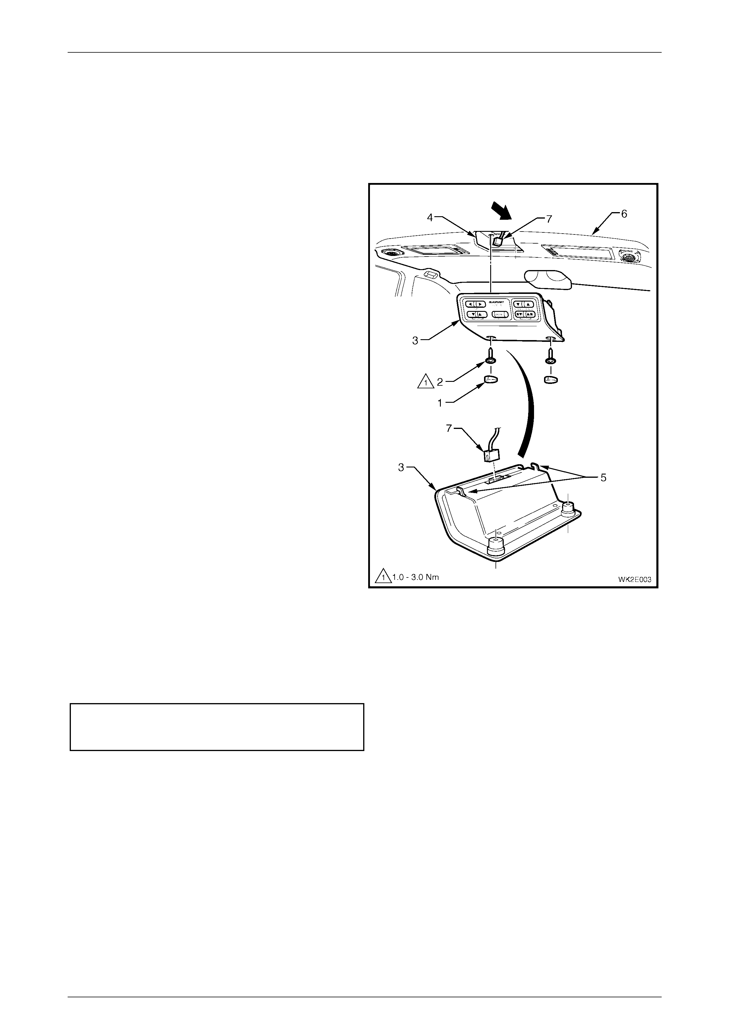
Entertainment System Page 12D–52
Page 12D–52
2.12 Rear Remote Control
LT Section No. 09–500
Remove
1 Remove blanking plugs (1) and screws (2) securing
the rear remote control assembly (3) to headlining
support (4).
NOTE
Take extreme care when removing the blanking
plugs from the rear remote control housing as
the housing can be easily damaged with
indentation mark s.
2 Disengage the locating lugs (5) and lower rear remote
control assembly from the headlining (6).
3 Disconnect the wiring harness connector (7) from the
rear remote control assembly and remove the
assembly from the headlining.
Figure 12D – 45
Reinstall
Installation of the rear remote control assembly is the reverse order of removal procedures, noting the following:
1 Tighten all screws to the specified torque.
Rear remote control
attaching screw torque
torque specific atio n .................................... 1.0 – 3.0 Nm
NOTE
For bulb replacement procedures relating to the
rear remote control, refer to Section 12B,
3.4 Rear Remote Control Bulbs in the MY 2003
VY and V2 Series Service Information.
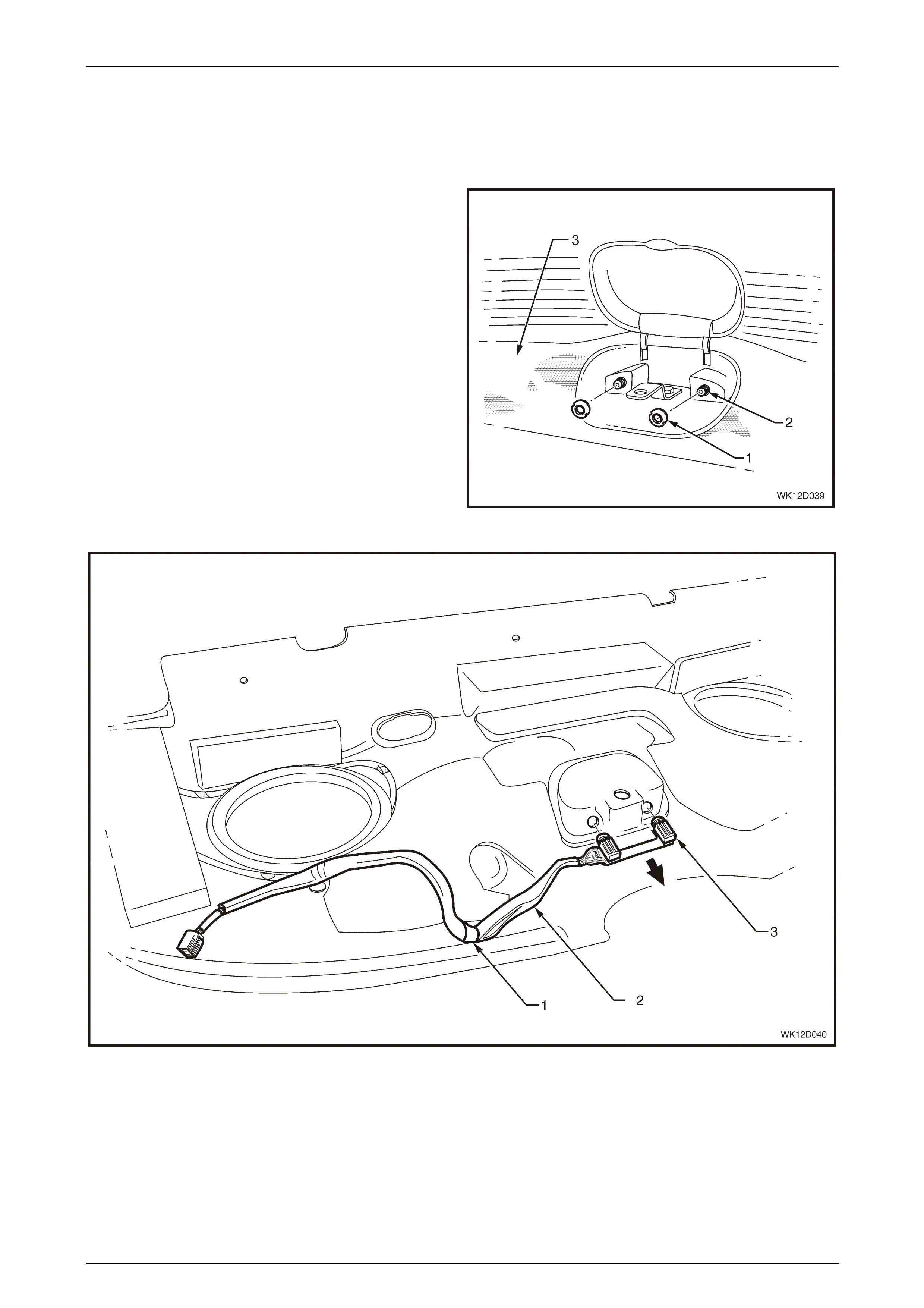
Entertainment System Page 12D–53
Page 12D–53
2.13 Rear Audio Headphone Jacks
Remove
1 Turn the ignition Off.
2 Remove the rear window trim panel assembly. Refer
to Section 1A8 Headlining and Interior Trim in this
Service Information.
3 Unscrew the two threaded nuts (1) securing the audio
jacks (2) to the trim panel (3).
Figure 12D – 46
Figure 12D – 47
4 Remove the clip (1) retaining the rear audio headphone jacks harness (2) to the trim panel.
5 Remove the rear audio headphone jacks and harness assembly (3).

Entertainment System Page 12D–54
Page 12D–54
Reinstall
Installation of the rear audio headphone jacks is the reverse order of the removal procedure, noting the following:
1 Tighten all threaded nuts to the specified torque.
Rear audio headphone jacks
attaching threaded nut
torque specific atio n .......................................Finger tight
2 Reinstall the rear window trim panel assembly. Refer to Section 1A8 Headlining and Interior Trim in this Service
Information.
3 Ensure the child anchor screw is tightened to the correct torque specification.
Child anchor attaching screw
torque specification ................................ 15.0 – 25.0 Nm

Entertainment System Page 12D–55
Page 12D–55
2.14 Dead Pan Assembly
Remove
1 Turn the ignition Off.
2 Remove the rear seat. Refer to Section 1A7, 7.2 Rear Seat Cushion Assembly in this Service Information.
3 Remove the two bolts and washers (1) securing the dead pan assembly (2) to the vehicle floor.
4 Disconnect the body wiring harness connector (3) and the left-hand and right-hand video screen connectors (4).
Remove the dead pan assembly.
Figure 12D – 48
Reinstall
Installation of the dead pan assembly is the reverse order of removal procedures, noting the following:
1 Tighten all bolts to the specified torque.
Dead pan assembly
attaching bolt
torque specification ...................................... 35 – 50 Nm
2 Relink the AIM to the BCM using TECH 2. Refer to 3.23 Security – Audio Interface Module.
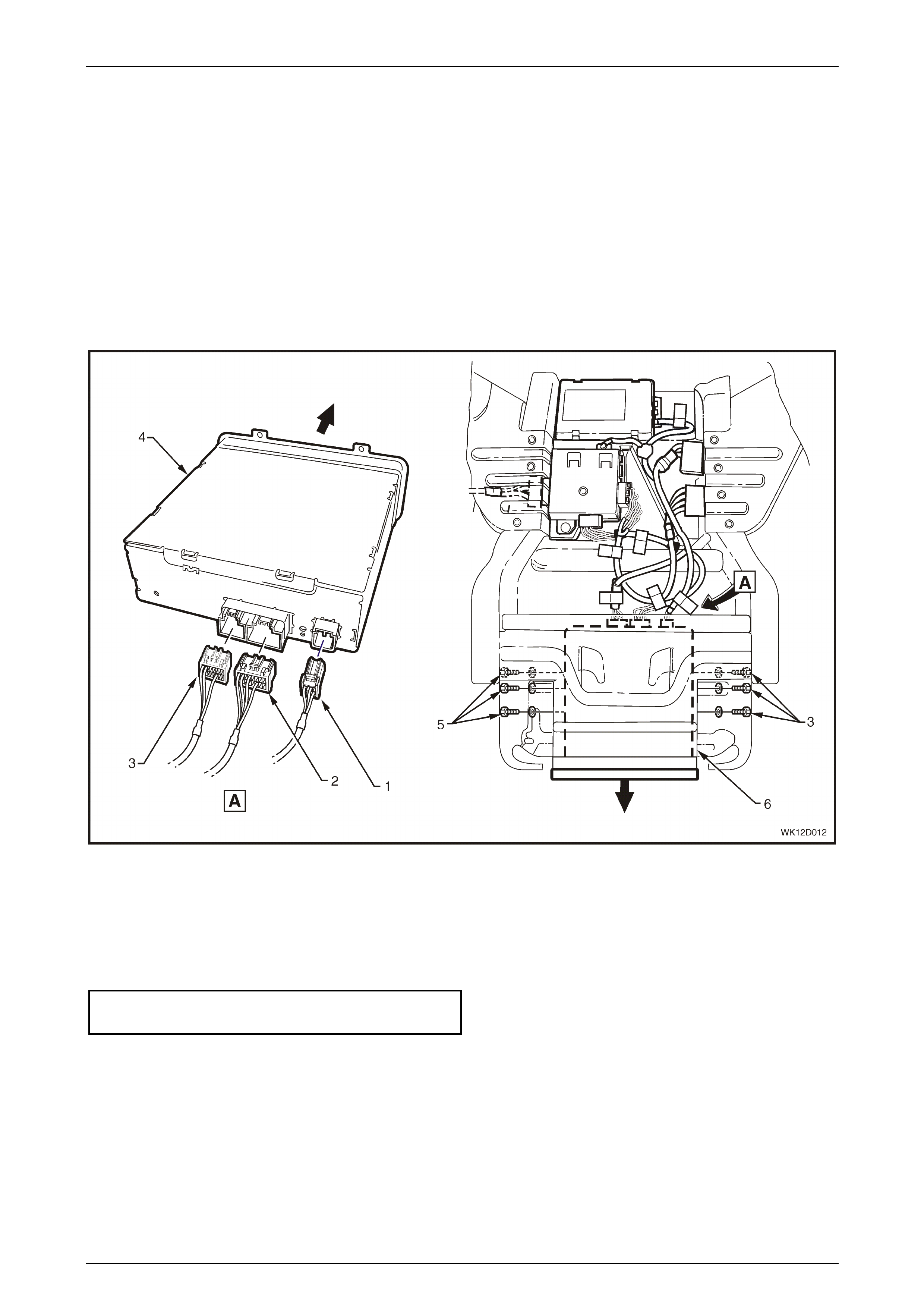
Entertainment System Page 12D–56
Page 12D–56
2.15 DVD Player
LT Section No. 09–515
Remove
1 Remove the dead pan assembly. Refer to 2.14 Dead Pan Assembly in this Section.
2 Disconnect the three wiring harness connectors A152-X3 (1), A152-X1 (2), A152-X2 (3) (marked with red tags)
from the back of the DVD player (4).
3 Remove the six bolts (5) securing the DVD player to the DVD player mounting bracket (6). Slide the DVD player
forward out of the mounting bracket.
Figure 12D – 49
Reinstall
Installation of the DVD player is the reverse order of removal procedures, noting the following:
1 Tighten all bolts to the specified torque.
DVD player attaching bolt
torque specification ................................ 0.65 – 0.95 Nm
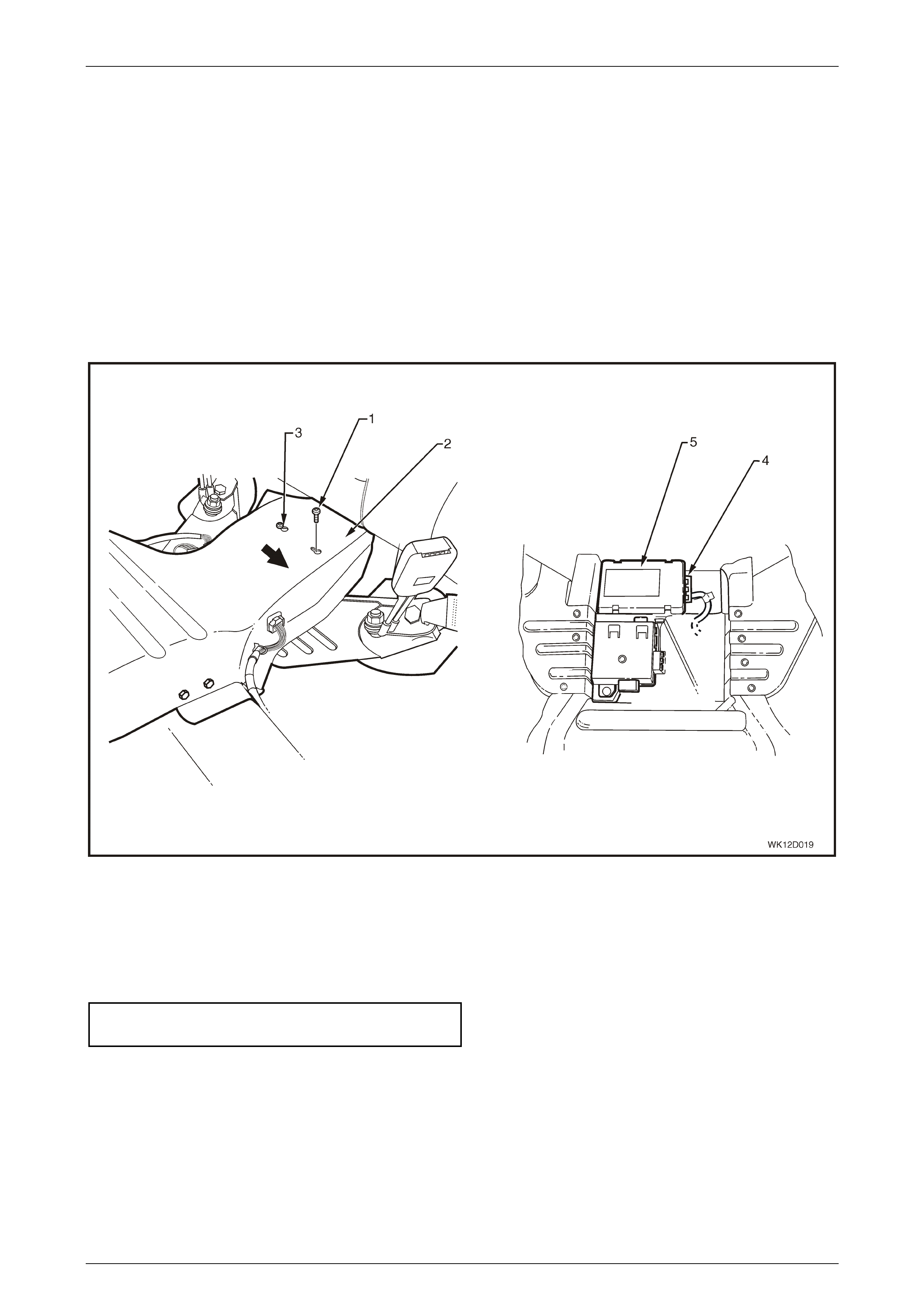
Entertainment System Page 12D–57
Page 12D–57
2.16 Audio Interface Module
LT Section No. 09–515
Remove
1 Remove the dead pan assembly. Refer to 2.14 Dead Pan Assembly in this Section.
2 Loosen the screw (1) securing the audio interface module to the dead pan assembly (2).
3 Slide the screw and locating lug (3) clear of the dead pan assembly.
4 Disconnect the body wiring harness connector (4) from the audio interface module (5) and remove module from the
dead pan assembly .
Figure 12D – 50
Reinstall
Installation of the audio interface module is the reverse order of removal procedures, noting the following:
1 Tighten all screws to the specified torque.
Audio interface module attaching screw
torque specific atio n .................................... 2.0 – 4.0 Nm
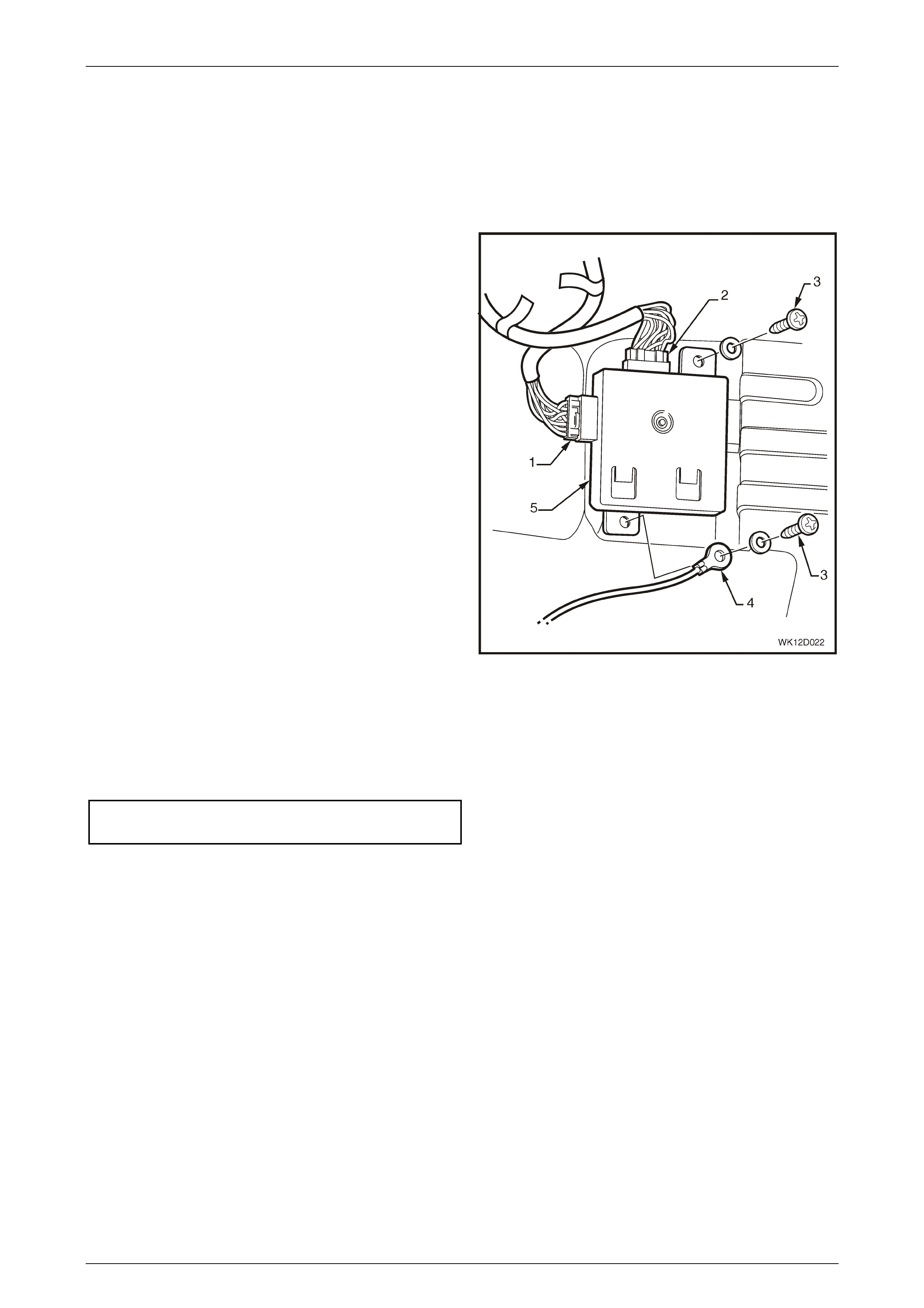
Entertainment System Page 12D–58
Page 12D–58
2.17 DVD Splitter
LT Section No. 09–515
Remove
1 Remove the dead pan assembly. Refer to 2.14 Dead
Pan Assembly in this Section.
2 Disconnect the right-hand DVD splitter connector (1)
marked with a green tag.
3 Disconnect the DVD connector (2) marked with a
yellow tag.
2 Remove the two screws (3) and earth harness (4)
attaching the DVD splitter (5) and remove DVD
splitter.
Figure 12D – 51
Reinstall
Installation of the DVD splitter is the reverse order of removal procedures, noting the following:
1 Tighten all screws to the specified torque.
DVD splitter attaching screw
torque specific atio n .................................... 2.0 – 4.0 Nm


Entertainment System Page 12D–60
Page 12D–60
2.19 Audio System Security Code
Code Entry
1 Switch the ignition on.
2 Switch the audio head unit on if turned off.
3 The display shows ’CODE 1_ _ _ _ ‘.
4 Use the preset buttons to enter the PIN code.
Example:
If the PIN code belonging to the radio is 3651.
Press Button Display
Press preset button 3 _ _ _
Press preset button 3 6 _ _
Press preset button 3 6 5 _
Press preset button 3 6 5 1
If a wrong PIN code has been entered the display will show ’CODE ERROR WAIT’.
After the waiting time ‘CODE 2 _ _ _ _’ will be shown on the display indicating that this is the second attempt. The correct
code should now be entered. After three attempts the delay time will be 1 hour. The display will show
“ONE HOUR LOCK-OUT”. After the delay time another three attempts at entering the code will be possible.
3
6
1
5

Entertainment System Page 12D–61
Page 12D–61
2.20 Audio System Master Reset
Reset Procedure
The following procedure resets the audio system parameters to the factory default settings.
1 Switch the ignition on.
2 Switch the audio head unit off.
3 Press and hold the ON button and the Memory Preset Station 4 button for at least 2 seconds.
The following table details the audio system parameters and the factory default settings.
NOTE
These parameters can also be reset from the
instrument cluster MFD in Customisation Mode.
Refer to Section 12C, 1.8 Customisation Mode in
the MY 2003 VY and V2 Series Service
Information for further details.
Parameters Range Default
Bass –6 to +6 STD (0)
Treble –6 to +6 STD (0)
Balance –6 to +6 STD (0)
Fader –6 to +6 STD (0)
Loudness On / Off On
Equaliser
Boost
On / Off
-2 to +2
Off
STD (0)
CD Random On / Off Off
CD Repeat On / Off Off
Local / Distance Local / Distance Distance
Display Mode Clock Adjust / Time Time
Audio Distortion Limiter On / Off On
Confirmation Beeps On / Off On
Speed Dependent Volume 0 to 5 2
DSP (Level 5 only)
Delay
Echo
On / Off
–3 to +3
–3 to +3
Off
STD (0)
STD (0)
Listening Position (Level 5 only) On / Off Off

Entertainment System Page 12D–62
Page 12D–62
3 Diagnostics
3.1 General Diagnostic Information
This audio system diagnosis is split into several parts.
1 The first part is a short description of the principles of radio operation. It is by no means exhaustive, and is to serve
only to give an understanding of how radios work and how to solve problems if they occur.
2 Many radio problems are caused by basic grounding and short-circuiting problems, which can be found quickly
using the checks included in the Basic Checks in this Diagnosis Section.
3 The most common fault is that of ‘static’ and so an explanation of what it is, what causes it and how to fix it is also
included.
4 Diagnostic charts are included to help diagnose common complaints.
Techline
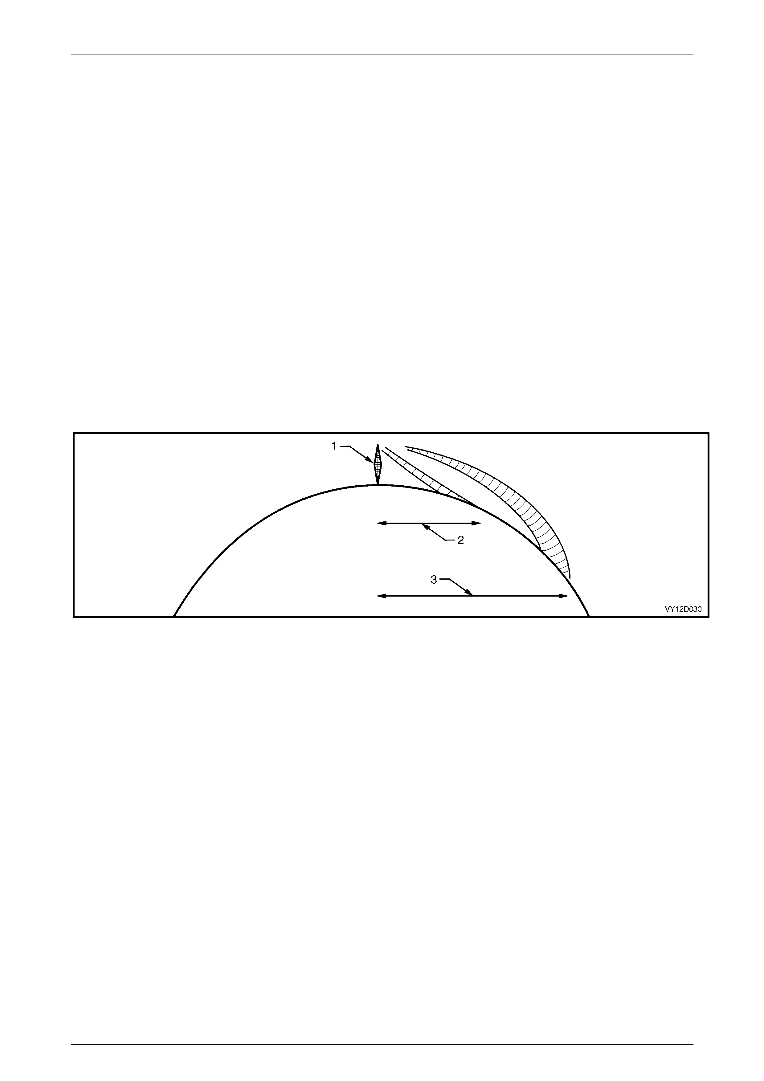
Entertainment System Page 12D–63
Page 12D–63
3.2 Principles Of Operation
Radio Reception
High quality radio reception is obviously more difficult to achieve in a moving vehicle than from a stationary location.
Audio systems fitted to vehicles incorporate sophisticated electronics to enhance radio reception by extending the
useable listening range whilst eliminating extraneous noises, such as static.
Many owners complain of ‘reception problems’, which are normal radio operating characteristics, particularly with FM.
Such complaints arise as a result of owner misconception as to what constitutes normal radio reception. Naturally, audio
head unit replacement under these circumstances will not affect the radio operating characteristics and has the potential
to create additional owner dissatisfaction. Thus a careful, well informed explanation of radio reception expectations is
more likely to enhance the owner’s understanding and satisfaction, as well as avoiding unnecessary repair costs and
inconvenience to the owner of the vehicle.
FM Reception In Vehicles
FM stereo’s maximum range is normally limited to 40 to 50 km. The strength of the FM signal is related to the distance
between the receiver and the transmitter. FM signals follow the line of sight, exhibiting many similar characteristics to
those of light. That is, similarly to sunlight, FM radio waves are cut off by the horizon. Since most FM transmitter towers
are nominally 100 metres from the ground, useable reception cannot extend much beyond the horizon. FM signals will
not bend around corners, but as with light, may be reflected (or blocked) by large objects.
Figure 12D – 52
Legend
1 Radio Transmissi on Tower 2 FM Transmission (40 – 50 km) 3 AM Transmissi on (up to several hundred
km)
Although FM signals will not bend around corners, they can be reflected by large objects, for example hills or buildings.
Because of these characteristics, a reflected signal and a direct signal can reach the radio’s antenna at the same time,
resulting in the signals interfering with each other or cancelling each other out. This obviously leads to a distortion of the
received signal or a loss of sound, and is known as multi-path interference.
Multi-path interference occurs only with FM reception and can be characterised by changes in distortion (static) levels
occurring as the vehicle is moving. This is due to the vehicle’s antenna entering and leaving FM signal interference
areas.
FM signal waves have short wavelength, which also means that the interference area is small – in the region of several
centimetres across. Because of the small size of interference areas, a vehicle may pass through many in a short time.
When the vehicle is stationary in an interference area, moving it half a metre can place the antenna in a region of clear
signal.
A vehicle fitted with a two antenna FM diversity system helps reduce multi-path interference by ensuring that at least one
antenna is outside the cancelled signal region.
Flutter or fading is caused when a vehicle passes into an area where the direct signal can be overshadowed by a
building, large structure or hill.
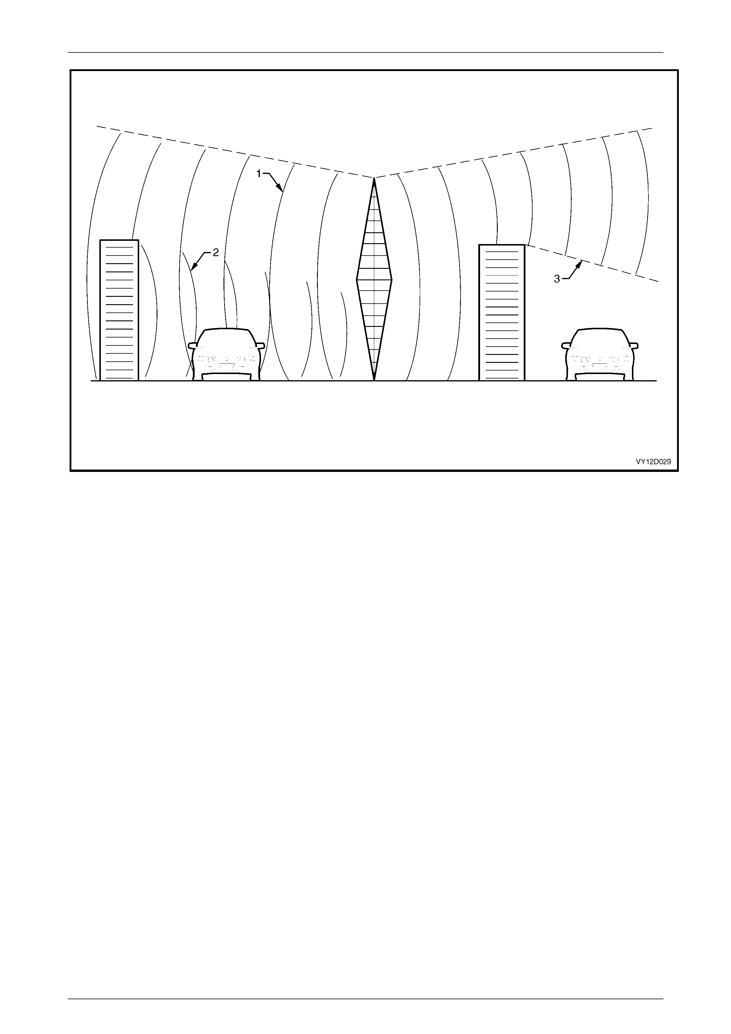
Entertainment System Page 12D–64
Page 12D–64
Figure 12D – 53
Legend
1 Main Signal Path 2 Multi-path Signal 3 Shadowed Signal
Atmospheric conditions can also affect FM reception. Unexplained loss of sensitivity can be caused by high humidity.
Cloudy days are also better for reception than clear days. With electronic tuning radios, users can sometimes be
confused by abbreviated radio station call signs. People who tune their radios to abbreviated call signal frequencies may
be slightly off the correct frequency.
NOTE
The following list details the AM and FM
frequency ranges for various regions.
Australian Range
FM: 87.5 MHz to 108.0 MHz, 0.1 MHz steps, 50 µs de-emphasis
AM: 522 kHz to 1710 kHz, 9 kHz steps
Gulf States Range
FM: 87.5 MHz to 108.0 MHz, 0.1 MHz steps, 50 µs de-emphasis
AM: 531 kHz to 1602 kHz, 9 kHz steps
Brazil Range, North / South America Range
FM: 87.5 MHz to 107.9 MHz, 0.2 MHz steps, 75 µs de-emphasis
AM: 530 kHz to 1710 kHz, 10 kHz steps
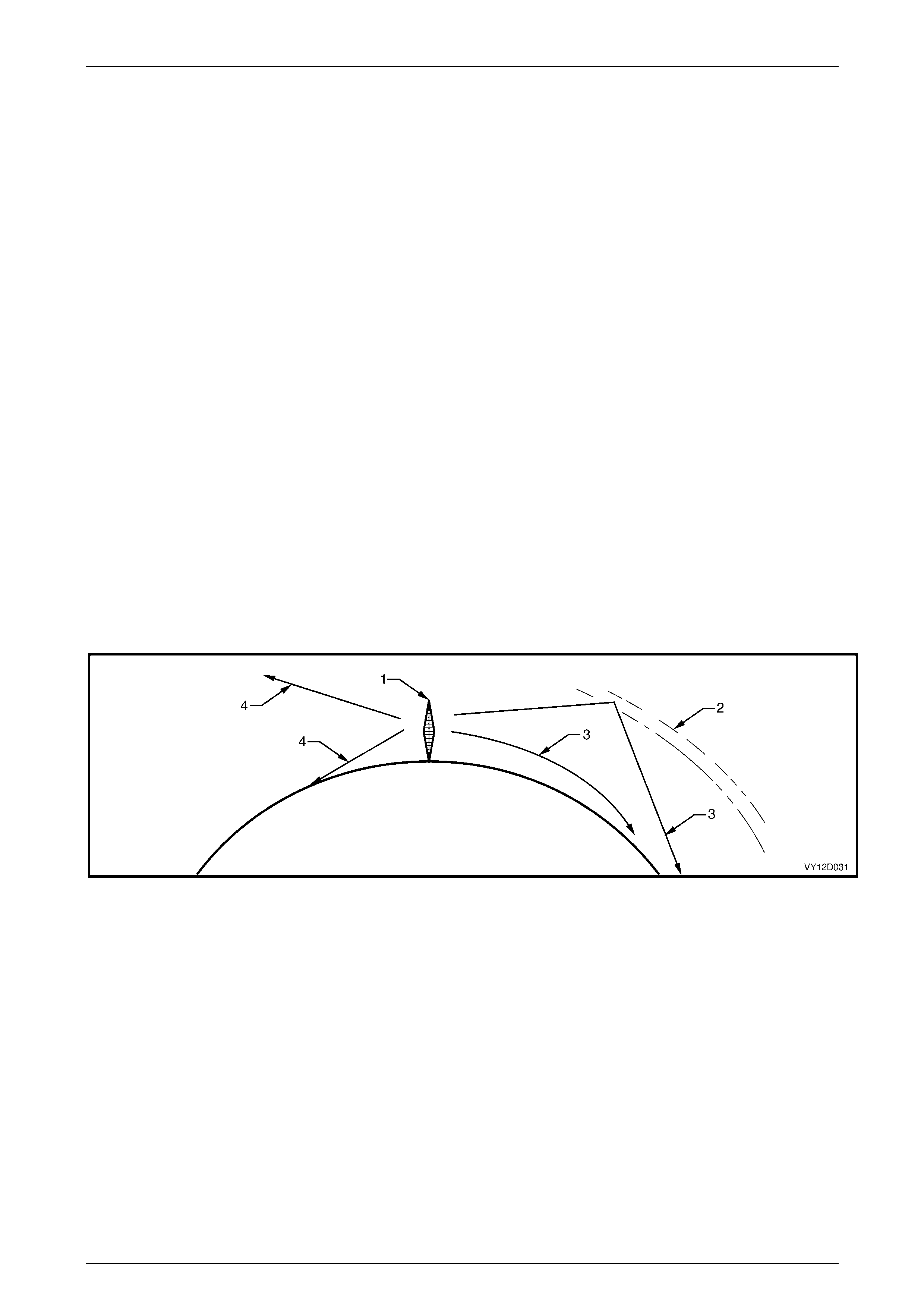
Entertainment System Page 12D–65
Page 12D–65
Asian Range, Israel Range, South Africa Range, Europe Range (without LW and RDS)
FM: 87.5 MHz to 108.0 MHz, 0.1 / 0.05 MHz steps, 50 µs de-emphasis
AM: 531 kHz to 1602 kHz, 9 kHz steps
Thailand Range
FM: 87.5 MHz to 108.0 MHz, 0.05 MHz steps, 50 µs de-emphasis
AM: 531 kHz to 1602 kHz, 9 kHz steps
Band Selection
The bands available are: FM1, FM2, FM ASM, AM and AM ASM.
Preset St atio n
Preset Memory:
FM1 six stations
FM2 six stations
FM ASM six stations
AM six stations
AM ASM six stations
AM Recept ion In Vehicles
In contrast to FM signals, AM signals will bend around corners and skip along the ground. This is due to AM signals
having longer wavelength and lower frequency. The layer of atmosphere known as the ionosphere can reflect the signal.
This phenomenon gives AM a longer reception range than FM, especially at night.
Figure 12D – 54
Legend
1 Radio Transmission Tower 3 AM Transmission
2 Ionosphere 4 FM Transmission
AM reception is affected by static induced by electrical power lines, traffic lights, electronic signs and thunderstorms.
Fade of AM signals can also be expected when driving through tunnels, underpasses, and in city centres.
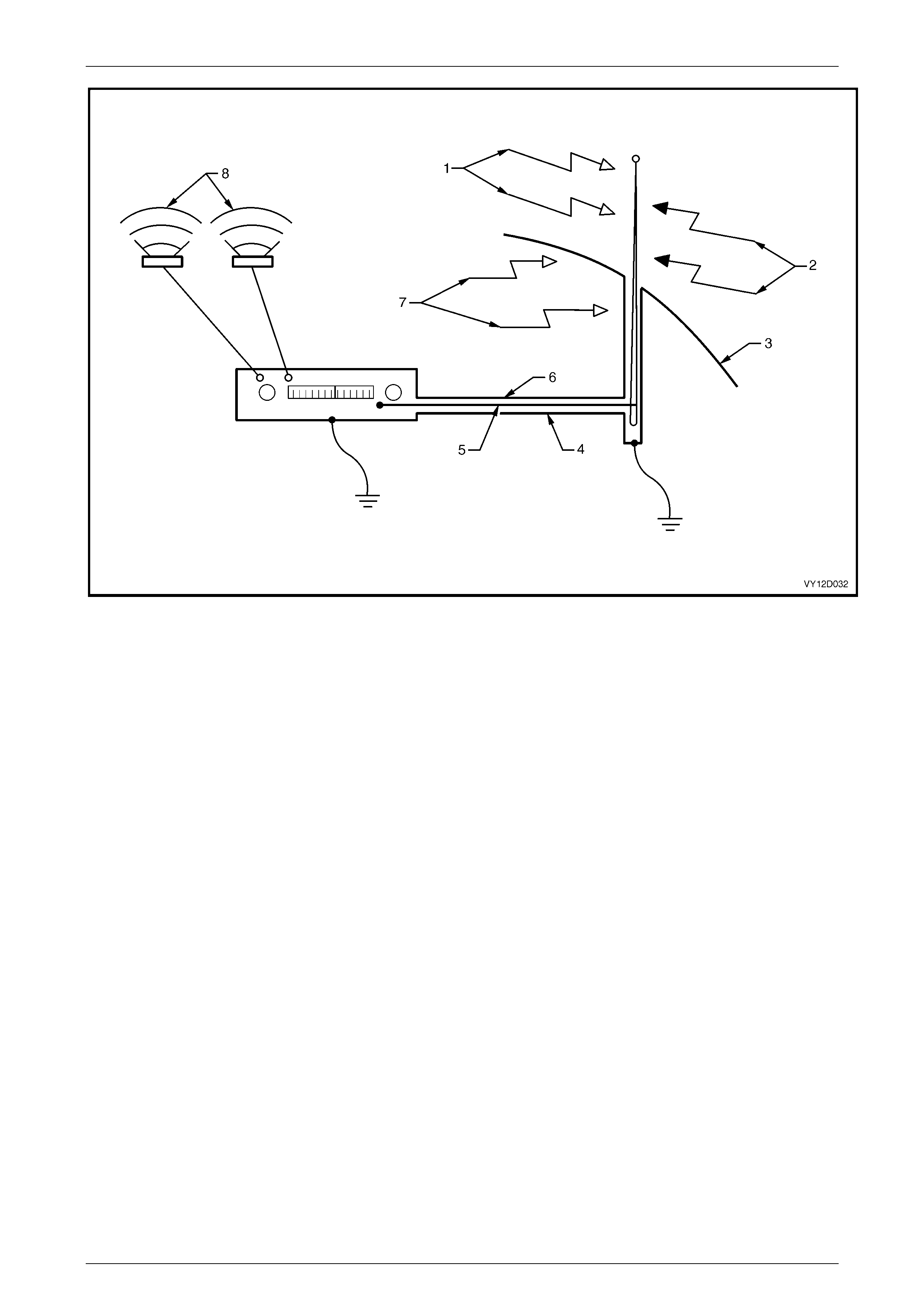
Entertainment System Page 12D–66
Page 12D–66
Figure 12D – 55
Legend
1 Signal from Radio Stati on 5 Antenna Cable Centre Core
2 External Interference 6 Antenna cable
3 Vehicle Body 7 Internal Interference
4 Antenna Cable Ground Braid 8 Music
As shown, signals from radio stations are picked up by the antenna and fed to the radio while being shielded from
interference sources by the braid. This is a complete electrical circuit, any breaks in the circuit, such as poor connections,
will result in poor reception.
Interference is due to the antenna system picking up signals other than those from the desired station. These
undesirable signals may be produced by electrical equipment in the vehicle itself, such as ignition, which is termed
‘internal interference’. Conversely, interference from sources outside the vehicle, such as from power lines, is known as
‘external interference’.
Internal interference is minimised by the shielding around the antenna wire, which prevents internal noise being picked
up and fed to the radio. The shielding around the core takes the form of a ‘braid’, which completes the electrical circuit
along which signals travel to the radio. Faults in this shielding system allow interference to reach the radio and hence be
reproduced at the speakers as noise.
It is therefore important that the shield of the antenna cable is effectively grounded at both the radio (to the radio case)
and at the antenna end (to the vehicle body), to ensure that minimal interference is received by the radio, and that the
optimum radio sensitivity is achieved.
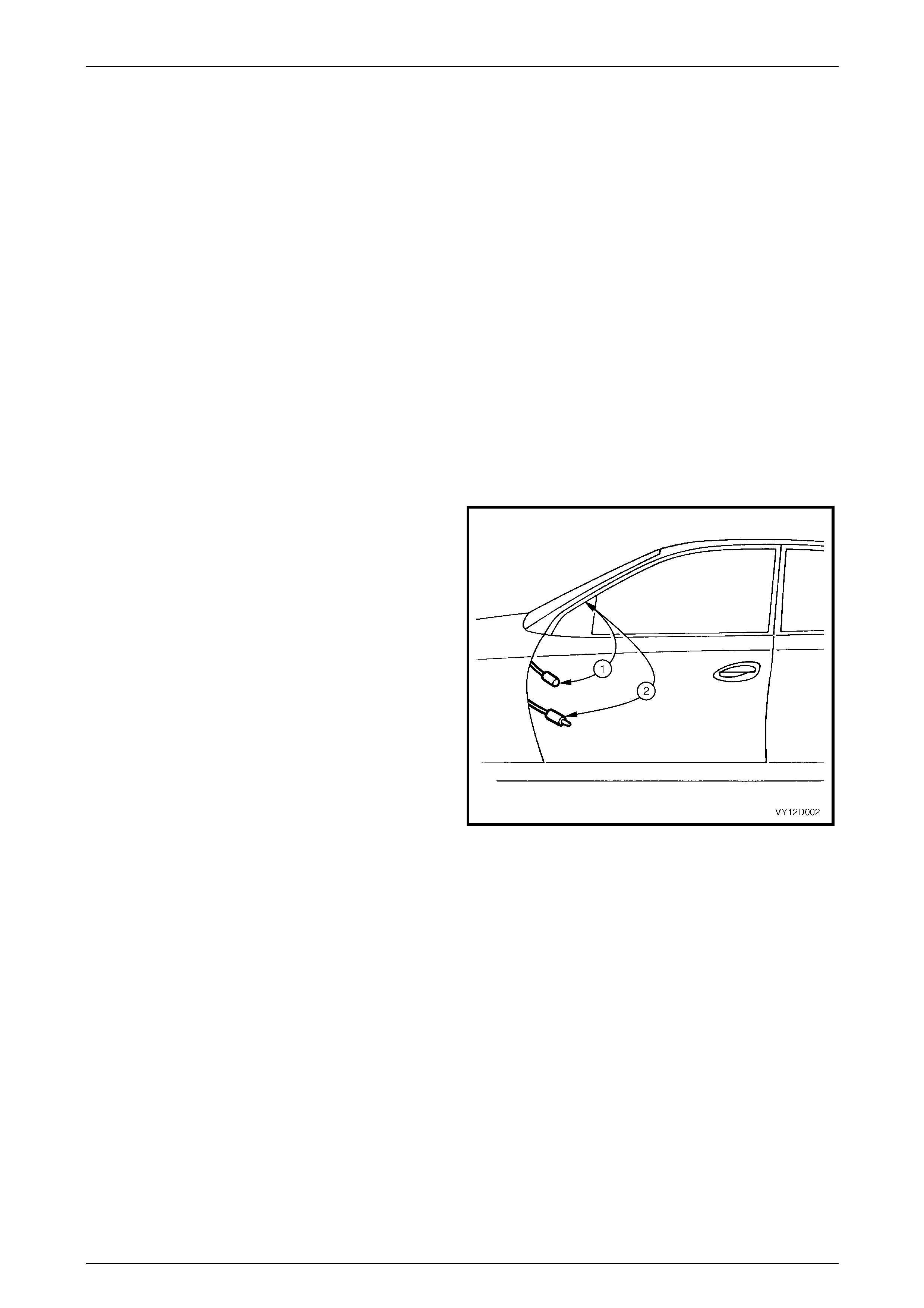
Entertainment System Page 12D–67
Page 12D–67
Basic Checks
Proper performance of the audio system depends greatly on grounding of the antenna and radio case to the vehicle
body, as it eliminates stray currents in the antenna circuit. Stray currents may be induced by wires running parallel to the
path of the radio or antenna wiring, or may be due to ‘noisy’ in-vehicle electrical items.
Resistances or connection quality of the major parts of the radio can be checked with an ohmmeter.
When using an ohmmeter to measure very low resistances, the lead resistance becomes considerable, and must be
subtracted from all subsequent readings. That is, touch the leads together, note the reading, and subtract this from all
subsequent readings.
NOTE
A very good contact point is required to measure
ground resistance. This point must not have
current flowing through it during measurement,
therefore ensuring that the ignition is turned off.
Avoid measuring using the screw on the door
jamb switch. The best place to measure ground
resistance is to use one of the self-tapping
screws retaining the A-pillar drip rail. Since these
screws are sometimes not properly grounded,
one of the screws may be removed to take
measurements directly to the body sheet metal.
1 Disconnect the battery negative terminal. Refer to
Section 00, 5. Battery Disconnection Procedures in
this Service Information.
NOTE
Failure to disconnect the battery negative
terminal may lead to incorrect resistance
measurements due to stray currents.
2 Disconnect the antenna extension lead from behind
the passenger side hinge pillar trim assembly.
3 Measure resistance from the outer of the antenna lead
to the vehicle body (1).
Resistance reading 0.3 ohm maximum.
4 Measure resistance from outer of the antenna
extension lead to the vehicle body (2).
Resistance reading 0.6 ohm maximum.
Figure 12D – 56
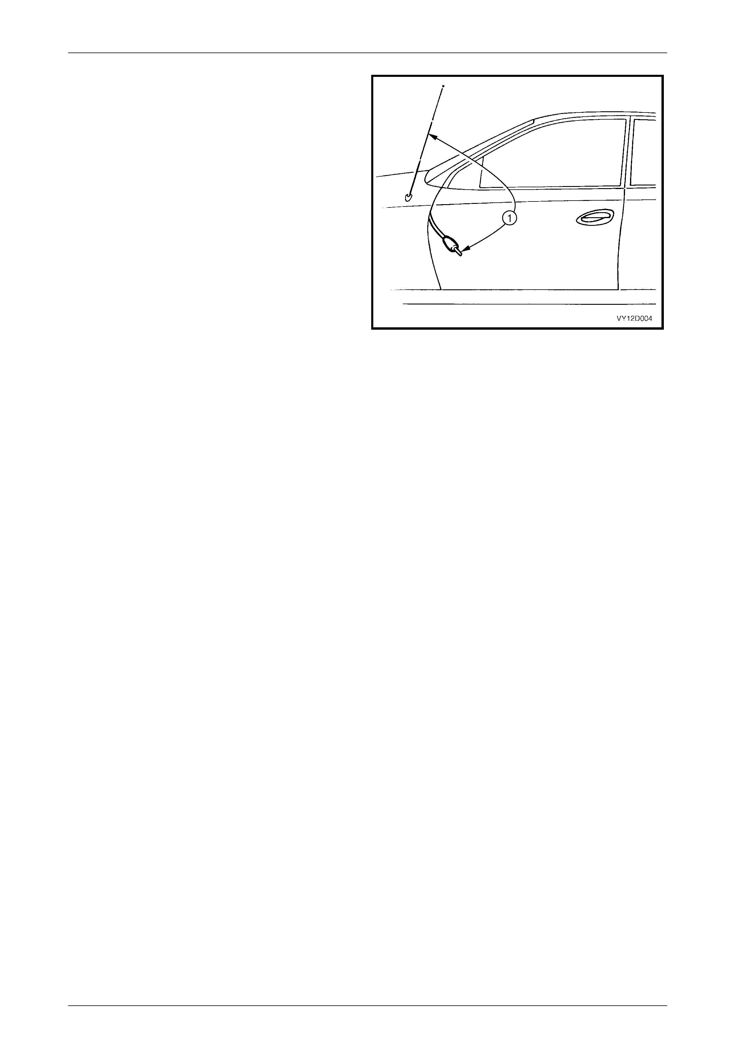
Entertainment System Page 12D–68
Page 12D–68
5 Check continuity of the path from the antenna cable
core to the antenna mast by measuring resistance (1).
Resistance reading 0.4 ohm maximum
NOTE
This test can in fact only be performed on power
antennas, since manually operated antennas are
fitted with in-line capacitors with the antenna
body, which misleadingly indicates an open
circuit when resistance is measured.
On vehicles with manually operated antennas,
disconnect the antenna lead from the antenna
lead extension and measure the resistance of
the extension lead cable core from the radio to
the antenna lead connection ends.
Resistance values significantly higher than those
sp ecifie d indi cate poor c onnect ions t hat m ust be
rectified before proper radio performance can be
obtained.
6 Check for shorts between the anten na core and the
braid by disconnecting from the radio and measuring
the resistance between the two. The measured value
should indicate an open circuit (very high or infinite
resistance).
7 Disconnect the antenna extension lead at both ends
and test the core for continu ity.
Figure 12D – 57
Common Radio Problems
Static
Static is a buzzing or crackling noise caused by the radio picking up unwanted radio waves and converting them to noise
output by the speakers.
The unwanted radio waves (interference) come from several sources, which can be put into two groups; internal and
external. As the names suggest, external interference comes from outside the vehicle, and is difficult to control, while the
vehicle generat es internal interference.
It must be emphasised that a radio system in good condition will protect itself from much static. Before trying to locate
and remove a source of interference it must first be determined that the shielding and grounding of the radio is in good
working order. This can easily be done by performing the tests detailed in the ‘Basic Checks’.
It should be noted that static may occur on weak stations, or when driving under bridges because signals from ignition
and the like become relatively stronger than the radio station signal, causing the ignition interference to become quite
strong. This could be due to stronger than normal ignition interference or a poorly functioning antenna.
If the cause cannot be isolated after performing the tests and trying to isolate a source of interference, using the following
procedures, it may be that the radio has an internal fault and requires repair.
External Interference
Static that occurs only while travelling in certain localities, such as near electrical transformers, is undoubtedly external
interference.
If there is any doubt whether the suspected source is causing interference, a simple check is to stop the vehicle and turn
off everything but the radio. If the source is external, the interference will continue and little can be done to eliminate it.
NOTE
The perceived interference level can be
significantly reduced, in noisy environments, by
slightly reducing the treble on the radio tone
controls.
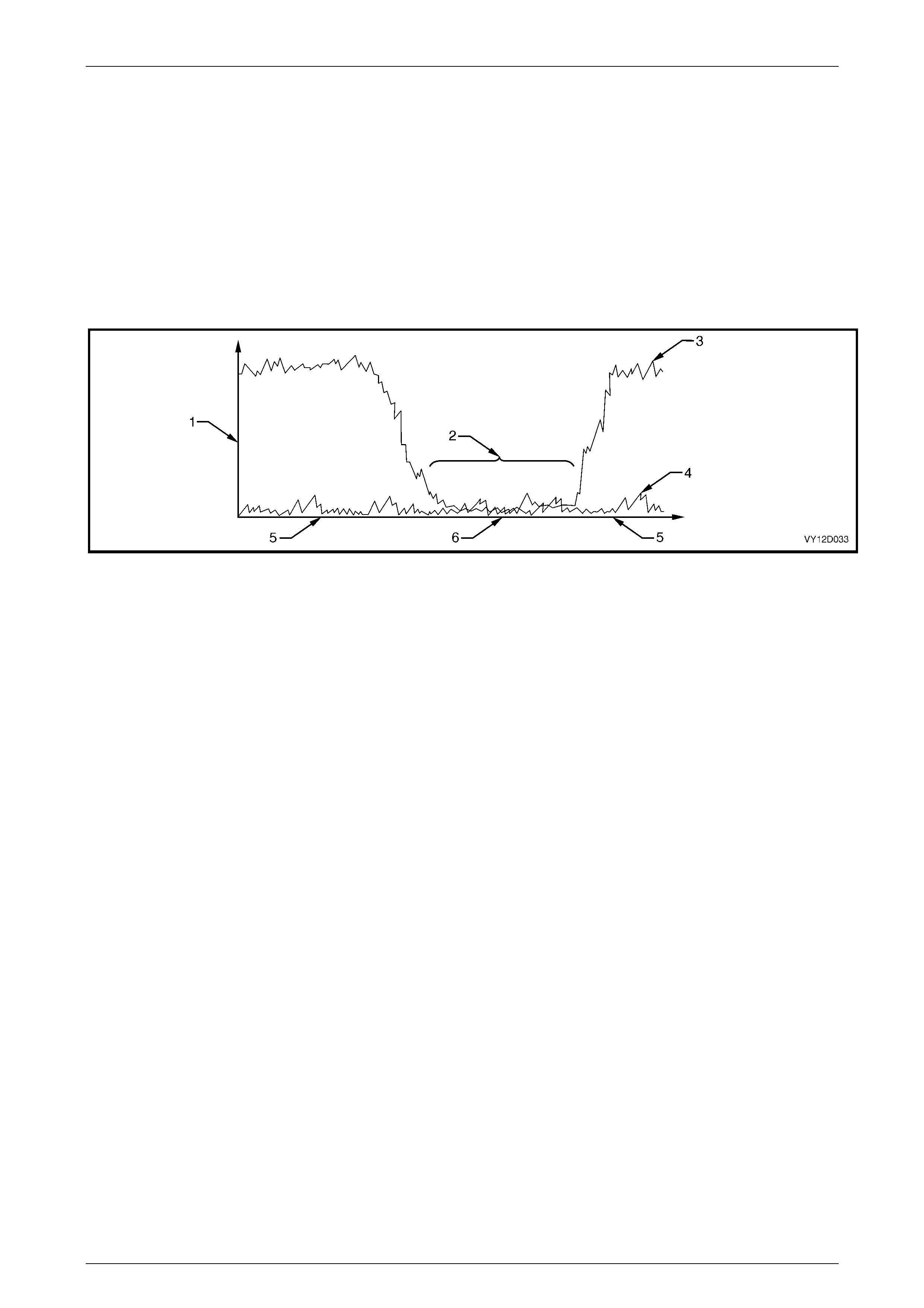
Entertainment System Page 12D–69
Page 12D–69
Internal Interference
Internal interference is that caused by some component of the vehicle’s electrical system, and may take many forms.
Many of the electrical items fitted to motor vehicles produce some sort of radio waves, but these radio waves only
become a problem if they are in the range of frequencies at which the radio receiver picks up and reproduces signals as
sound. For the radio, the vehicle’s electrical system must be designed not to emit radio signals at the frequencies of the
AM and FM bands.
Components are sometimes fitted with suppressing devices as part of their design, and failure of these suppressors may
allow the item to start interfering with radio operation.
Interference will be worse on weak stations, since a strong signal normally overpowers the interfering signal. Interference
can occur when the signal strength drops below a certain threshold, such as driving under a bridge, inside a workshop,
or in the shadow of a building. This situation is shown in the following figure.
Figure 12D – 58
Legend
1 Signal Strengt h 3 Signal at Antenna from Radio Station 5 Normal Reception
2 In-vehicl e Nois e Int erferes with
Tuned Station 4 In-vehicle Noise 6 Reception Blocked
Static may be caused by many internal sources. If static is at ignition frequency, varying with engine speed, the ignition is
the culprit. However, many electrical faults will cause static which otherwise would not be heard. Examples of ignition
interference sources are:
1 Plug leads breaking down.
2 Carbon tracking (arcing) to ground.
3 Faulty spark plugs.
4 Inoperative interference shields.
The actual cause of the interference can be isolated through carefully noting the circumstances under which the problem
occurs. For example, if it occurs only at speeds above approximately 80 km/h in an automatic transmission equipped
vehicle quite possibly it is the electrical signal being sent to the torque converter clutch.
Other sources of static can be:
1 Electric cooling fan.
2 Electric fuel pump.
3 Normal computer ‘noi se’ at certain frequencies .
4 Windshield wipers or washers.

Entertainment System Page 12D–70
Page 12D–70
Diagnosing Internal Interfere nce
If a vehicle has an interference problem that only occurs when the engine is turned on, or some other repeatable
circumstance, carry out the following procedure:
1 Park the vehicle in an open area, as far away from buildings as possible. Turn the radio onto the band (AM\FM)
and frequency where the complaint occurs, with the ignition in the Accessories position.
2 Reproduce the interference, eg. turn the ignition on.
3 If interference is due to a fan blower motor, etc. and is judged to be objectionable, try a similar specification vehicle
in the same location. If this is not possible, the component should be substituted to determine whether it is faulty.
NOTE
Internal interference is often a symptom of a
defective radio system, such as poor antenna
grounding, etc. If substituting a new component
does not fix the condition, the problem is very
likely to be in the radio system, and the
resistance checks in this Section should be
performed.
4 Whistles / squeals that occur only when the ignition is on, are probably due to electronic modules in the vehicle
creating interference when active (power applied). These modules may be isolated as a cause of interference by
removing power to them and rechecking. This is best done by turning the ignition off, removing the fuse that
supplies that particular item with power, turning the ignition back on and rechecking. By process of elimination, the
‘noisy’ module should be able to be found. Once found, substitute the module to find out whether the interference is
normal.
Speakers
Before removing speakers suspected of being noisy or faulty, ensure that any distortion that may be present is not due to
any of the following:
1 Foreign matter such as sand lying on the speaker cone, especially horizontally mounted speakers such as the
subwoofers.
2 Cable ties or other such material resting on the back of the speaker cone.
3 Incorrectly fitted speaker mesh or loose trim around speaker assembly.
4 Distortion of the speaker assembly caused by the angled insertion of the speaker retaining screws. Loosening and
tightening the screws while being careful not to distort the speaker cone may rectify the speaker problem.

Entertainment System Page 12D–71
Page 12D–71
3.3 Audio System Diagnostics
Fault diagnosis for the audio system is divided into two areas; faults which can be remedied by checking the operation of
audio system and it's sub components (DVD Player, Audio Interface Module and Premium Sound Amplifier), and those
which can be checked by using the TECH 2 Diagnostic Tool.
Diagnostic Trouble Codes
When a fault is detected, the audio system or it's sub component sets a Diagnostic Trouble Code (DTC) that represents
that particular problem or failure. The DTC remains current as long as the fault remains, and is cleared when the fault is
rectified. The DTCs can be read and cleared using the TECH 2.
Each DTC is allocated a number. For further details on each of the DTCs, refer to 3.7 Diagnostic Trouble Code – Audio
System in this Section.
Audio System Input / Output Signals
Voltages in the following table are typical voltages that will be read at the audio head unit connector while the radio is on,
ignition is on and the radio is in AM or FM mode. Some variation in the values can be expected due to changing battery
voltages and normal tolerances.
Pin Number Function Typical Voltage
X1-A1 Secondary Serial Data Bus Typically 4.5 V with digital meter
X1-A2 Battery Voltage Sense Input +12 V (battery voltage)
X1-A3 Telephone Mute 3.9 V with no telephone mute, 0 V with telephone mute
X1-A4 Accessories Input 0 V accessories off, +12 V accessories on
X1-A5 Antenna Trigger 0 V Radio off or CD mode, +12 V in radio mode
X1-A6 Illumination Input 0 V park lamps off, +12 V park lamps on
X1-A7 Battery Supply Voltage +12 V (battery voltage)
X1-A8 Ground 0 V
X1-B1 Right Rear Speaker Output + Cannot read with digital meter
X1-B2 Right Rear Speaker Output – Cannot read with digital meter
X1-B3 Right Front Speaker Output + Cannot read with digital meter
X1-B4 Right Front Speaker Output – Cannot read with digital meter
X1-B5 Left Front Speaker Output + Cannot read with digital meter
X1-B6 Left Front Speaker Output – Cannot read with digital meter
X1-B7 Left Rear Speaker Output + Cannot read with digital meter
X1-B8 Left Rear Speaker Output – Cannot read with digital meter
X1-C1 LH Rear Headphone Output Cannot read with digital meter
X1-C2 RH Rear Headphone Output Cannot read with digital meter
X1-C3 Rear Headphones Ground 0 V
X1-C4 Rear Headphones Trigger
X1-C5 DVD RH Audio Out
X1-C6 DVD LH Audio Out
X1-C7 Telephone Audio + Cannot read with digital meter
X1-C8 Telephone Audio – Cannot read with digital meter

Entertainment System Page 12D–72
Page 12D–72
Pin Number Function Typical Voltage
X1-C9 DVD Audio Out Ground 0 V
X1-C10 Rear Roof Remote Input
X1-C11 Rear Roof and Horn Bar Remote
Control Input 3.95 V no button pressed, 1.95 V Mute button pressed
X1-C12 Horn Bar Remote Control Ground 0 V
X1-C16 MFD Serial comms 3-4 V
X1-C18 DVD Audio In Ground
X1-C19 DVD LH Audio In
X1-C20 DVD RH Audio In
X2-A Main Antenna Input Cannot read with digital meter
X2-B Main Antenna Ground 0 V
X3-A Diversity Antenna Input Cannot read with digital meter
X3-B Diversity Antenna Ground 0 V
Figure 12D – 59

Entertainment System Page 12D–73
Page 12D–73
3.4 Connecting TECH 2 For System
Diagnosis
TECH 2, with the appropriate software, cables and
adaptors, is capable of reading the audio system serial data
when connected to the Data Link Connector (DLC). The
DLC is connected to the instrument panel lower trim panel
retainer, below the steering column.
1 Data Link Connector (DLC)
2 DLC Adaptor
3 DLC Cable
4 TECH 2
For additional general information on connecting and
operating TECH 2, refer to Section 0C, TECH 2 in this
Service Information.
Figure 12D – 60
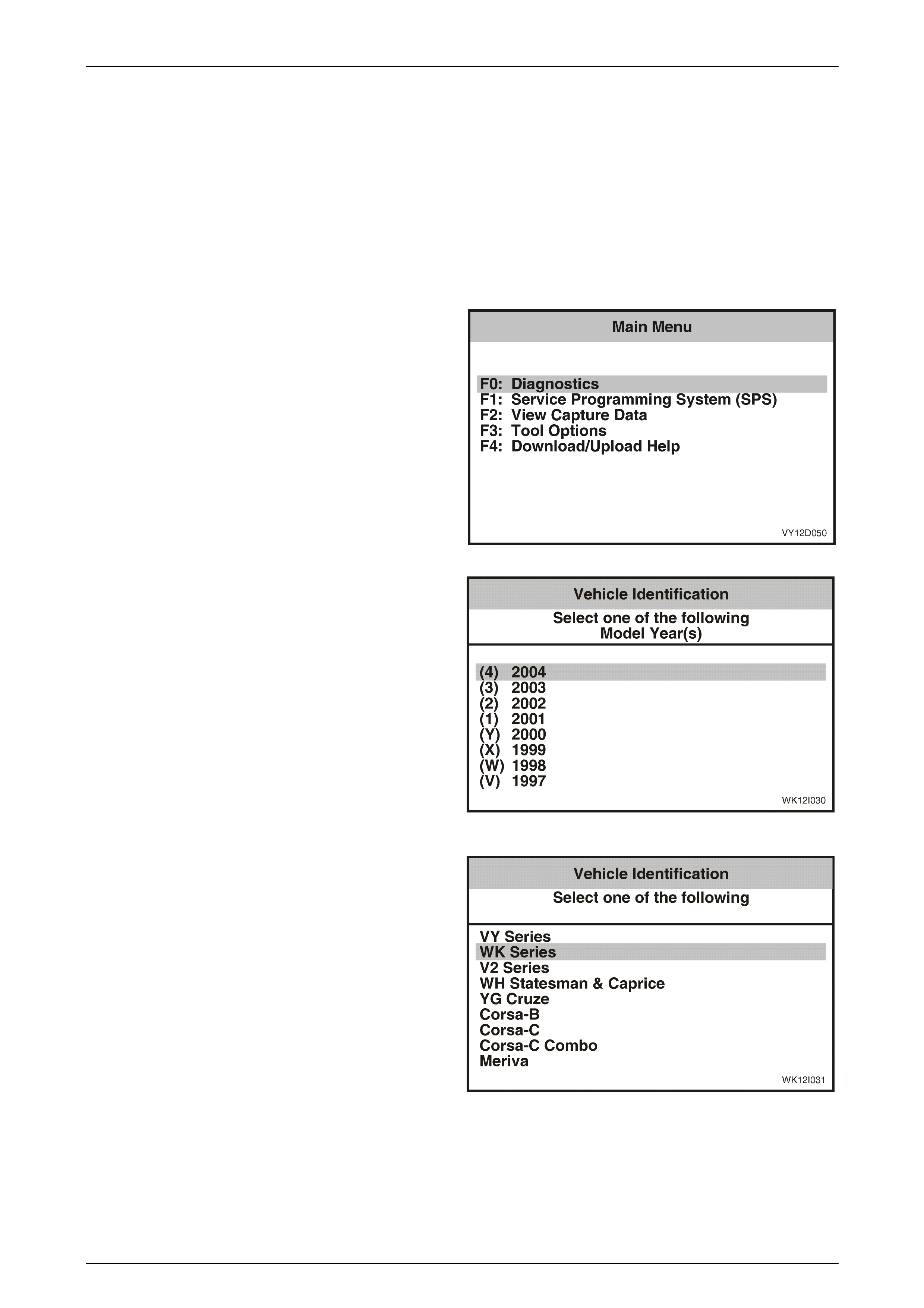
Entertainment System Page 12D–74
Page 12D–74
3.5 TECH 2 Test Modes And Displays
A prerequisite of this diagnostic section is for the user to be familiar with the proper use of TECH 2. The following pages
illustrate only the major TECH 2 screen displays and provide a brief explanation of their function for diagnosing the audio
system. If additional information is required on the operation of TECH 2, reference should be made to either Section 0C
TECH 2 in this Service Information or the TECH 2 User’s Guide.
With the ignition turned off, connect TECH 2 to the Data Link Connector (DLC) using the DLC Adaptor, refer to
3.4 Connecting TECH 2 For System Diagnosis in this Section.
Main Menu
Turn the ignition on and press the power button (PWR) on
the TECH 2.
The TECH 2 will perform a series of self-diagnosing power
on self-tests (POST). Once this has been completed
successfully, the TECH 2 start-up screen will be displayed.
Press the Enter key to continu e.
The Main Menu screen is displayed.
Press the F0 function button or Select F0: Diagnostics by
using the arrow keys until F0: Diagnostics is highlighted and
press the Enter key.
Figure 12D – 61
Model Year
Select 2004 from the model year list and press Enter.
Figure 12D – 62
Vehicle Identification Menu
Select the appropriate vehicle type from the list and press
Enter.
Figure 12D – 63
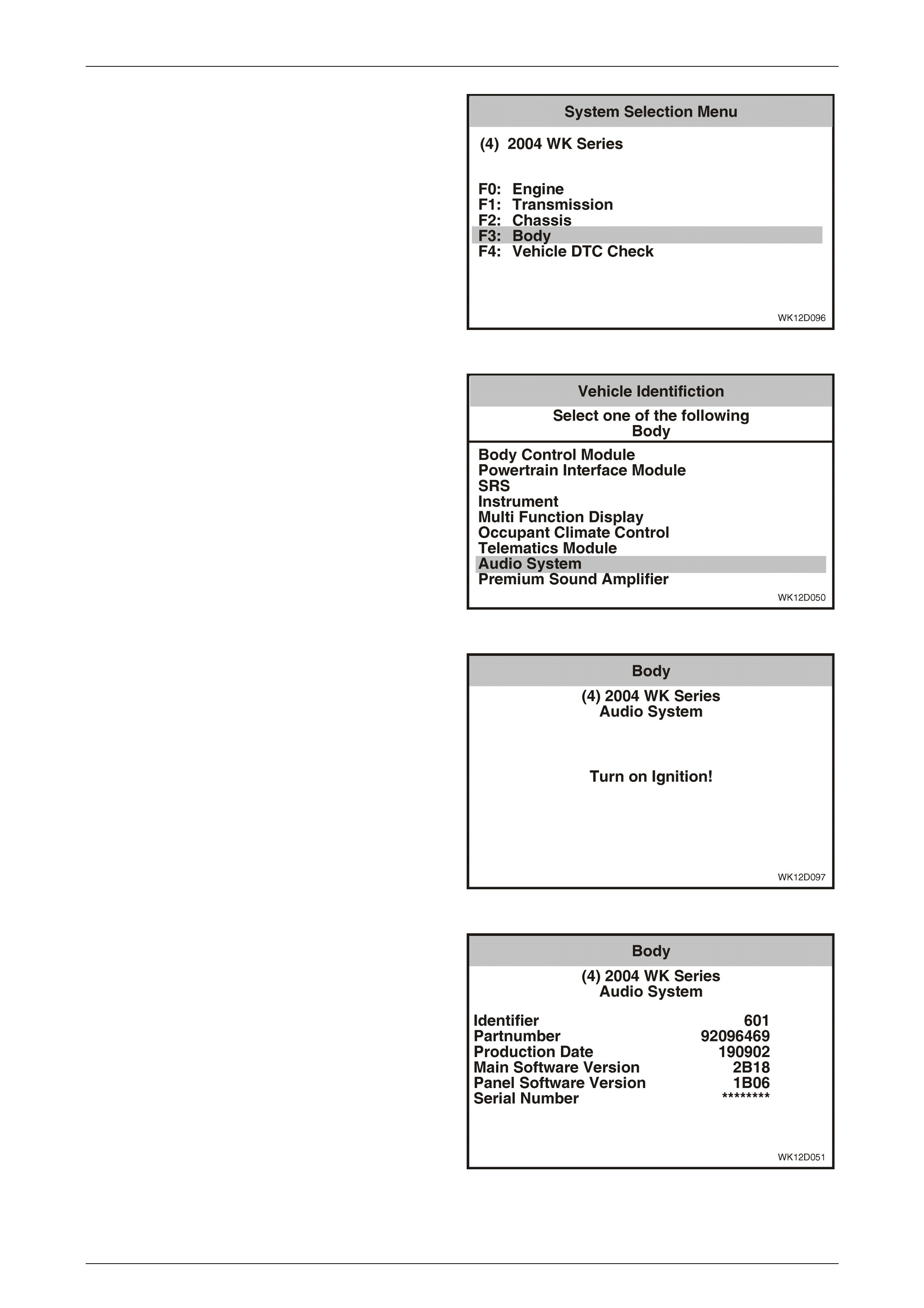
Entertainment System Page 12D–75
Page 12D–75
System Selection Menu
Select F3: Body from the System Selection Menu and press
Enter.
Figure 12D – 64
Audio System Select ion
Select the Audio System and press Enter.
Figure 12D – 65
Turn the ignition on (as requested) and press the Confirm
soft key to continue.
Figure 12D – 66
The audio system identification details will be displayed.
Scroll through the list using the TECH 2 Up and Down
arrows.
Figure 12D – 67
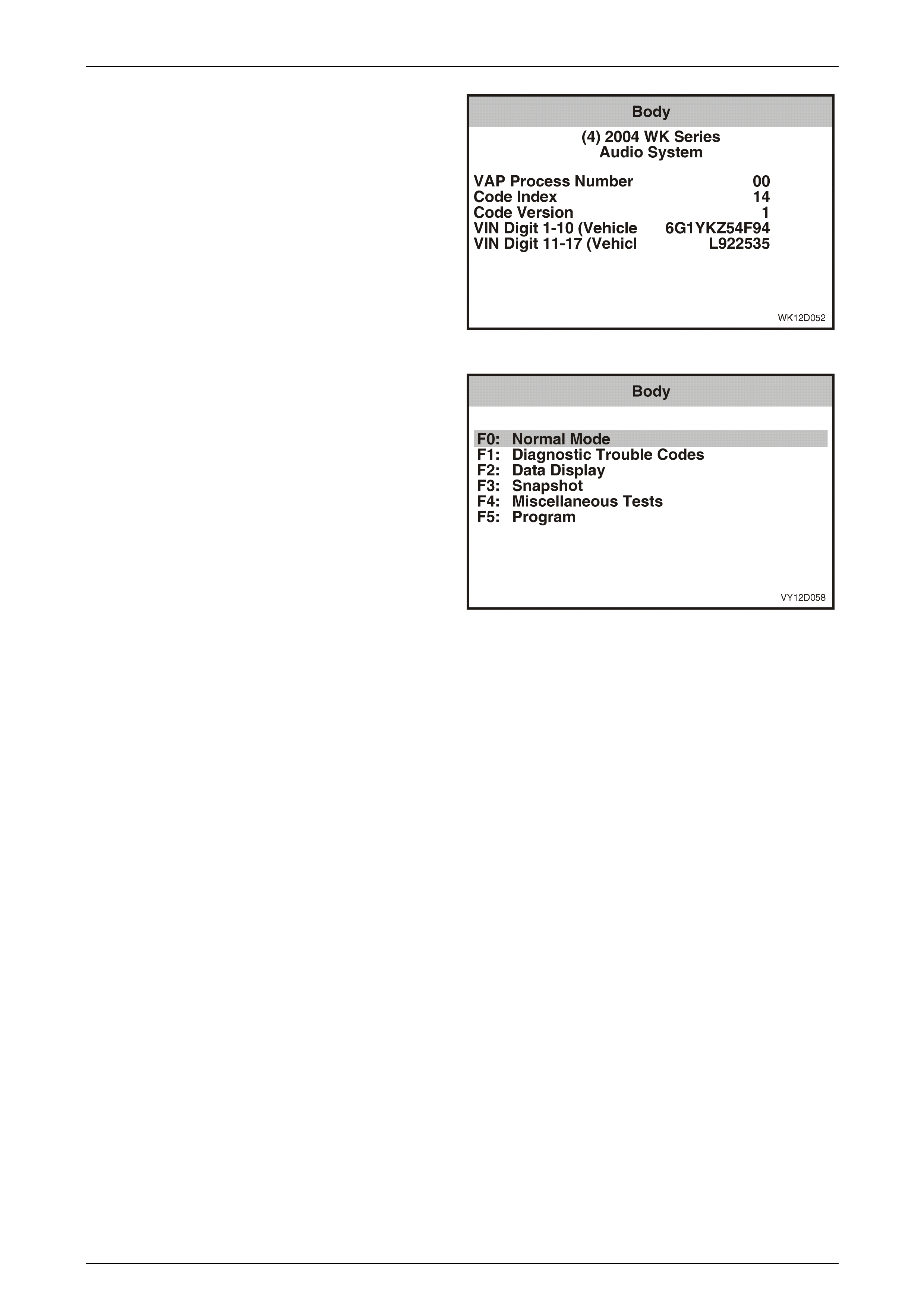
Entertainment System Page 12D–76
Page 12D–76
Press the Confirm soft key to confirm these details.
Figure 12D – 68
This menu provides the TECH 2 user with access to the
various functions used to diagnose faults in the audio
system.
The following audio system functions are available:
F0: Normal Mode
The normal mode data list is used to view serial data being
sent from the audio syste m. Refer to 3.6 Normal Mode –
Audio System in this Section.
F1: Diagnostic Trouble Codes
In this mode Diagnostic Trouble Codes can be read and
cleared. Refer to 3.7 Diagnostic Trouble Codes – Audio
System in this Section.
F2: Data Display
In this mode, TECH 2 displays the status of inputs and
outputs of the audio system. Refer to 3.8 Diagnostic Data
Display – Audio System in this Section.
F3: Snapshot
In this test mode, the TECH 2 captures data before and
after a forced manual error. Refer to 3.9 Snapshot – Audio
System in this Section.
F4: Miscellaneous Tests
In this test mode, the TECH 2 can test and diagnose faults
in the audio system. Refer to 3.10 Miscellaneous Tests –
Audio System in this Section.
F5: Program
Audio system information can be programmed when this
mode is selected. Refer to 3.11 Program – Audio System in
this Section.
Figure 12D – 69
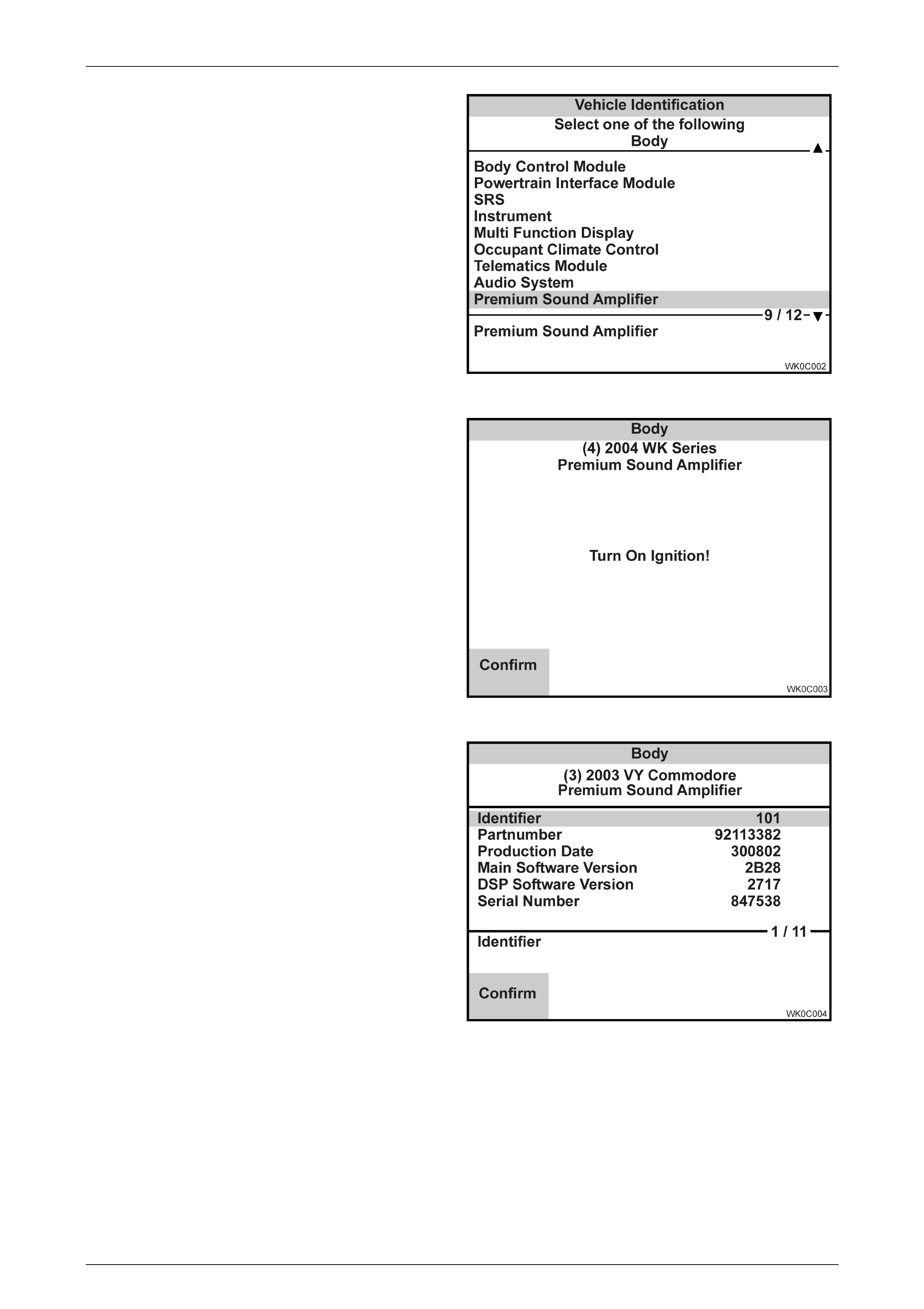
Entertainment System Page 12D–77
Page 12D–77
Premium Sound Amplifier Selection
Select the Premium Sound Amplifier and press Enter.
Figure 12D – 70
Turn the ignition on (as requested) and press the Confirm
soft key to continue.
Figure 12D – 71
The premium sound amplifier identification details will be
displayed. Press the Confirm soft key to confirm these
details.
Figure 12D – 72

Entertainment System Page 12D–78
Page 12D–78
This menu provides the TECH 2 user with access to the
various functio ns use d to diag nose faults in the pr emium
sound amplifier.
The following premium sound amplifier functions are
available:
F0: Diagnostic Trouble Codes
In this mode Diagnostic Trouble Codes can be read and
cleared. Refer to 3.13 Diagnostic Trouble Codes – Premium
Sound Amplifier in this Section.
F1: Data Display
In this mode, TECH 2 displays the status of inputs and
outputs of the premium sound amplifier. Refer to
3.14 Diagnostic Data Display – Premium Sound Amplifier in
this Section.
F2: Snapshot
In this test mode, the TECH 2 captures data before and
after a forced manual error. Refer to 3.15 Snapshot –
Premium Sound Amplifier in this Section.
F3: Miscellaneous Tests
In this test mode, the TECH 2 can test and diagnose faults
in the premium sound amplifier. Refer to 3.16 Miscellaneous
Tests – Premium Sound Amplifier in this Section.
F4: Program
The premium sound amplifier can be programmed when this
mode is selected. Refer to 3.17 Program – Premium Sound
Amplifier in this Section.
Figure 12D – 73
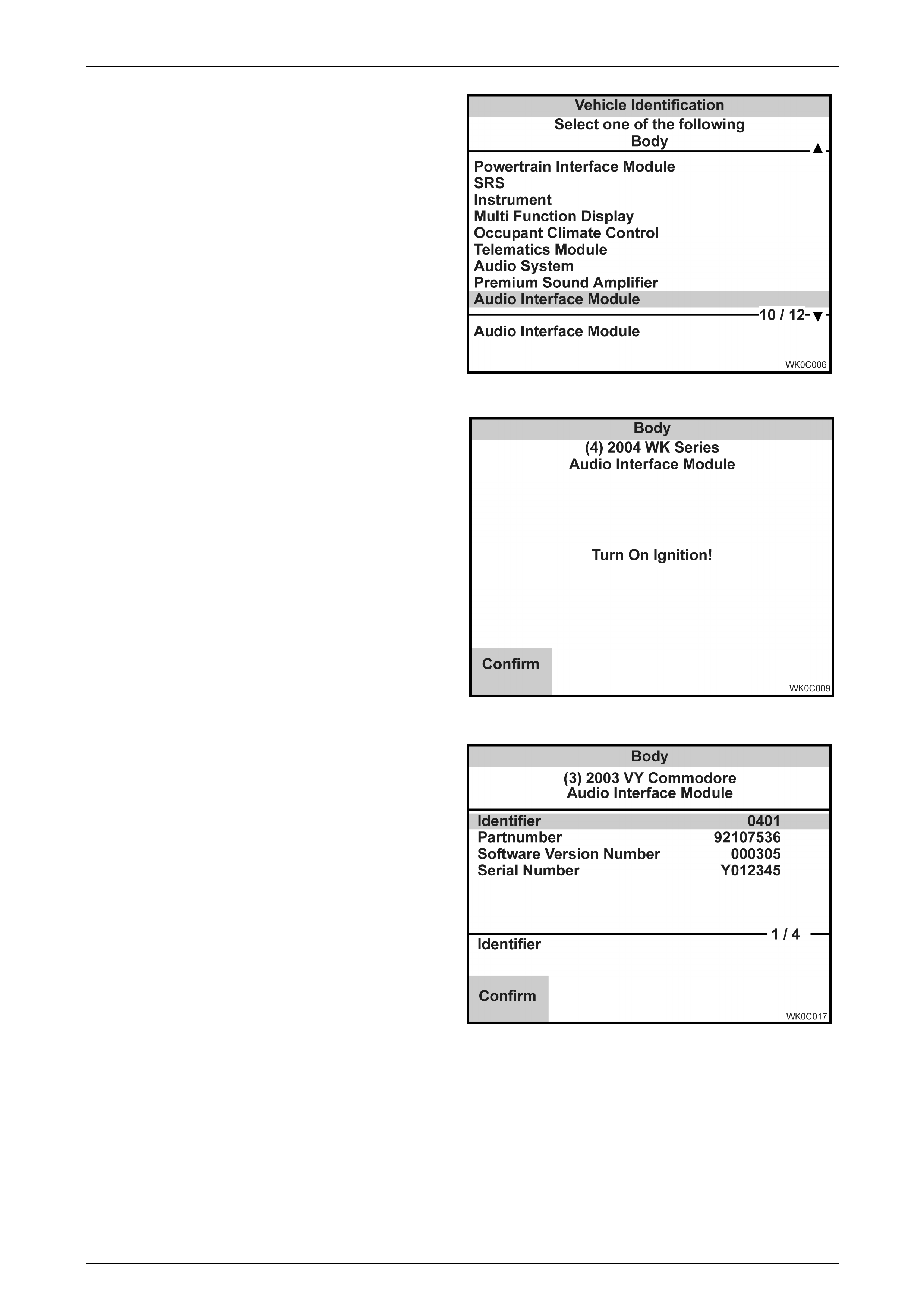
Entertainment System Page 12D–79
Page 12D–79
A udio Interface Module Selection
Select the Audio Interface Module and press Enter.
Figure 12D – 74
Turn the ignition on (as requested) and press the Confirm
soft key to continue.
Figure 12D – 75
The audio interface module identification details will be
displayed. Press the Confirm soft key to confirm these
details.
Figure 12D – 76
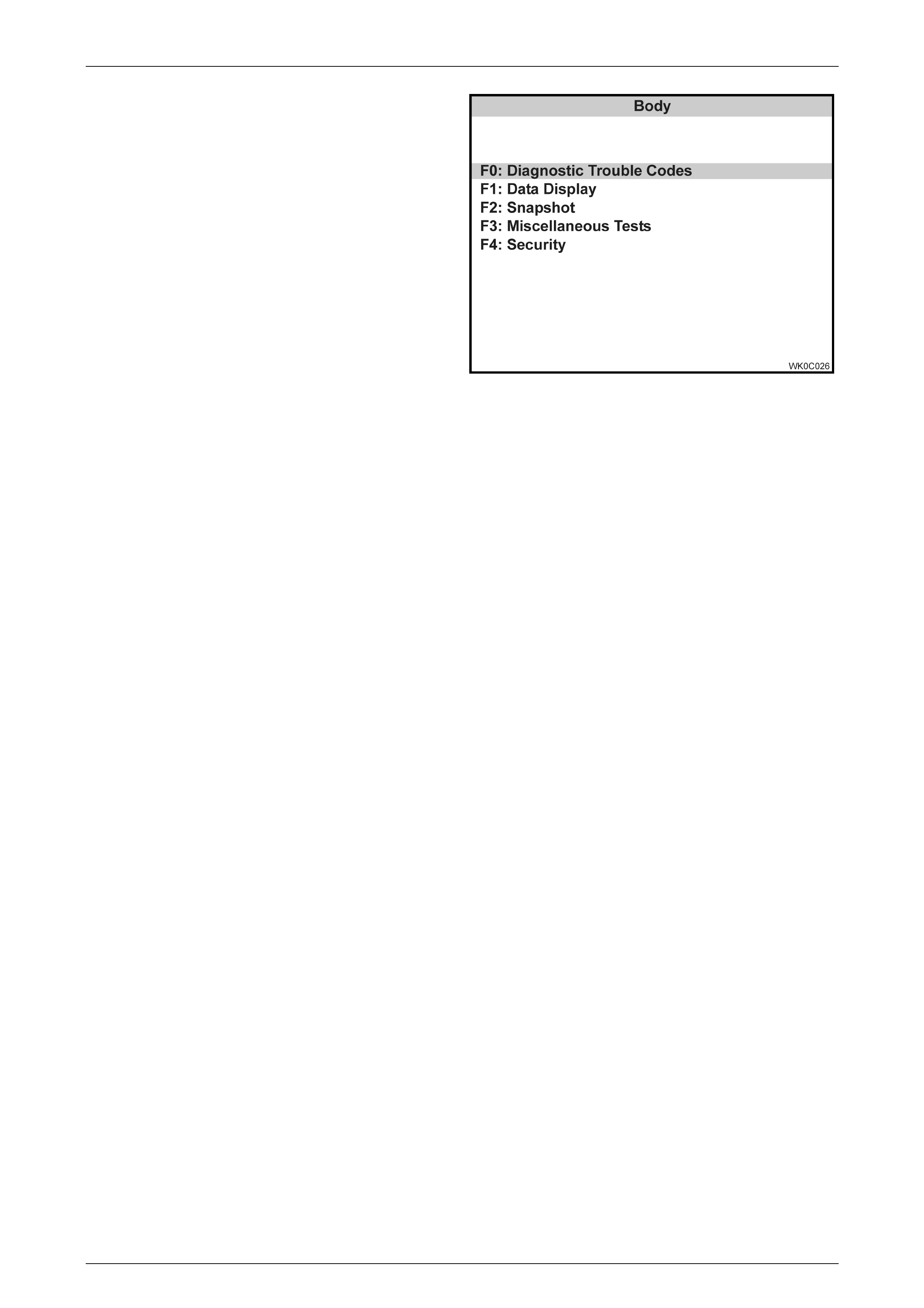
Entertainment System Page 12D–80
Page 12D–80
This menu provides the TECH 2 user with access to the
various functio ns use d to diagnose faults in the audio
interface mo dule .
The following audio interface module functions are
available:
F0: Diagnostic Trouble Codes
In this mode Diagnostic Trouble Codes can be read and
cleared. Refer to 3.19 Diagnostic Trouble Codes – Audio
Interface Module in this Section.
F1: Data Display
In this mode, TECH 2 displays the status of inputs and
outputs of the audio interface module. Refer to
3.20 Diagnostic Data Display – Audio Interface Module in
this Section.
F2: Snapshot
In this test mode, the TECH 2 captures data before and
after a forced manual error. Refer to 3.21 Snapshot – Audio
Interface Module in this Section.
F3: Miscellaneous Tests
In this test mode, the TECH 2 can test and diagnose faults
in the audio interface module. Refer to 3.22 Miscellaneous
Tests – Audio Interface Module in this Section.
F4: Security
In this mode, TECH 2 can be used to link and unlink the
audio interface module with the body control module. Refer
to 3.23 Security – Audio Interface Module in this Section.
Figure 12D – 77
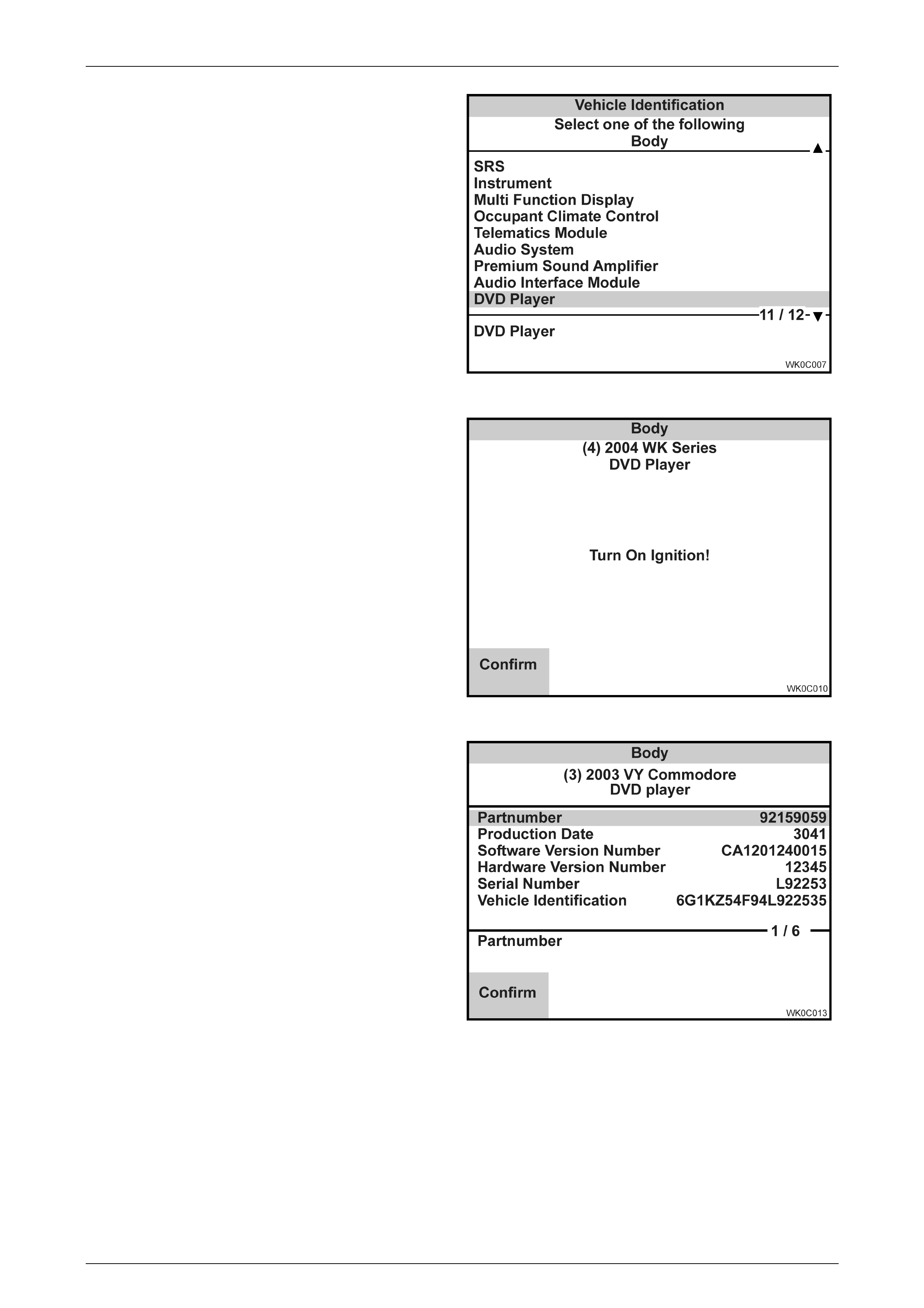
Entertainment System Page 12D–81
Page 12D–81
DVD Player Select ion
Select the DVD Player and press Enter.
Figure 12D – 78
Turn the ignition on (as requested) and press the Confirm
soft key to continue.
Figure 12D – 79
The DVD player identification details will be displayed.
Press the Confirm soft key to confirm these details.
Figure 12D – 80
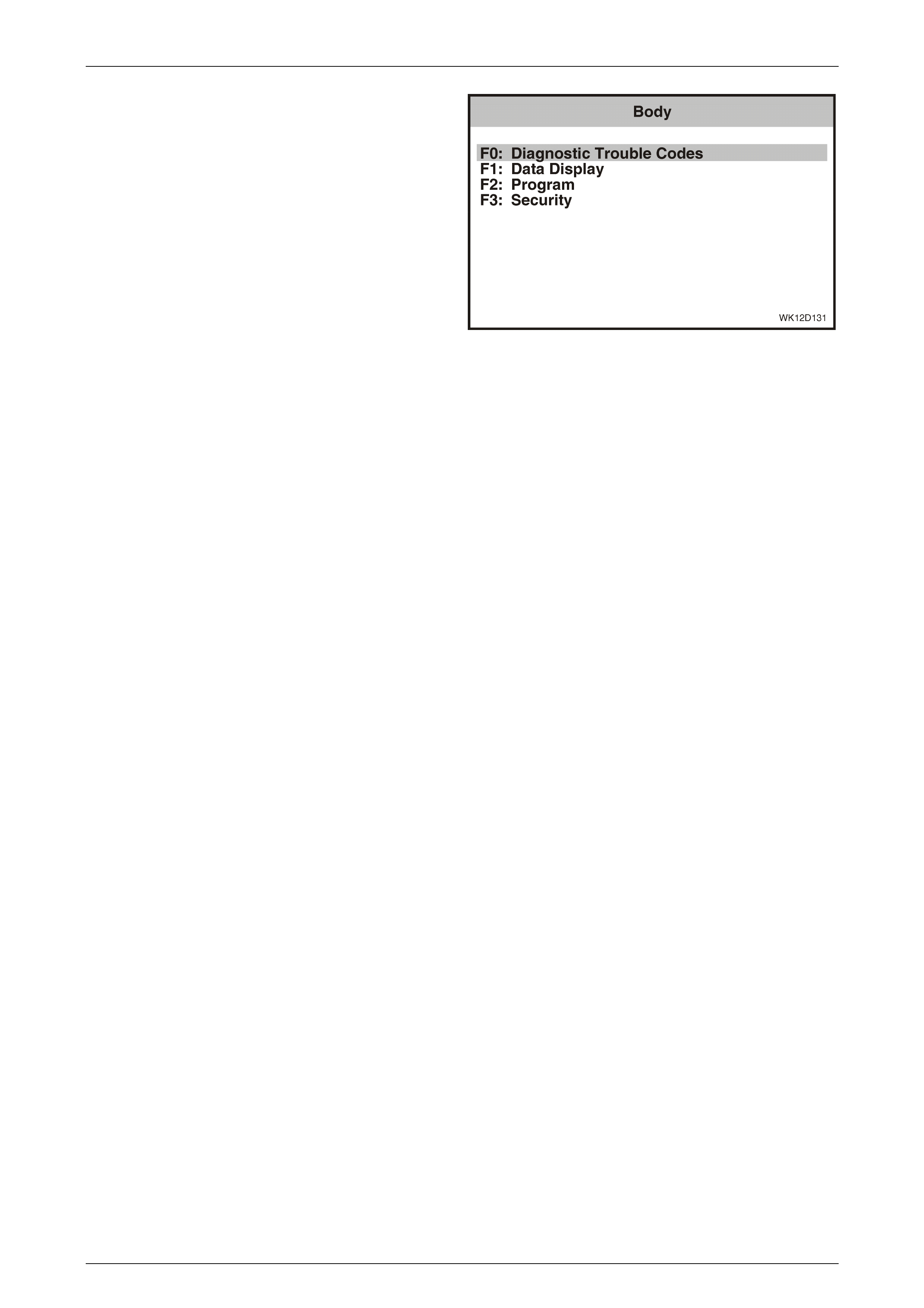
Entertainment System Page 12D–82
Page 12D–82
This menu provides the TECH 2 user with access to the
various functions used to diagnose faults in the DVD player.
The following DVD player functions are available:
F0: Diagnostic Trouble Codes
In this mode, Diagnostic Trouble Codes can be read and
cleared. Refer to 3.25 Diagnostic Trouble Codes – DVD
Player in this Section.
F1: Data Display
In this mode, TECH 2 displays the status of inputs and
outputs of the DVD player. Refer to 3.26 Data Display –
DVD Player in this Section.
F2: Program
In this mode, the TECH 2 can be used to program the
region code and video format of the DVD player. Refer to
3.28 Program – DVD Player in this Section.
F3: Security
In this mode, TECH 2 can be used to link and unlink the
audio interface module with the body control module. Refer
to 3.29 Security – DVD Player in this Section.
Figure 12D – 81
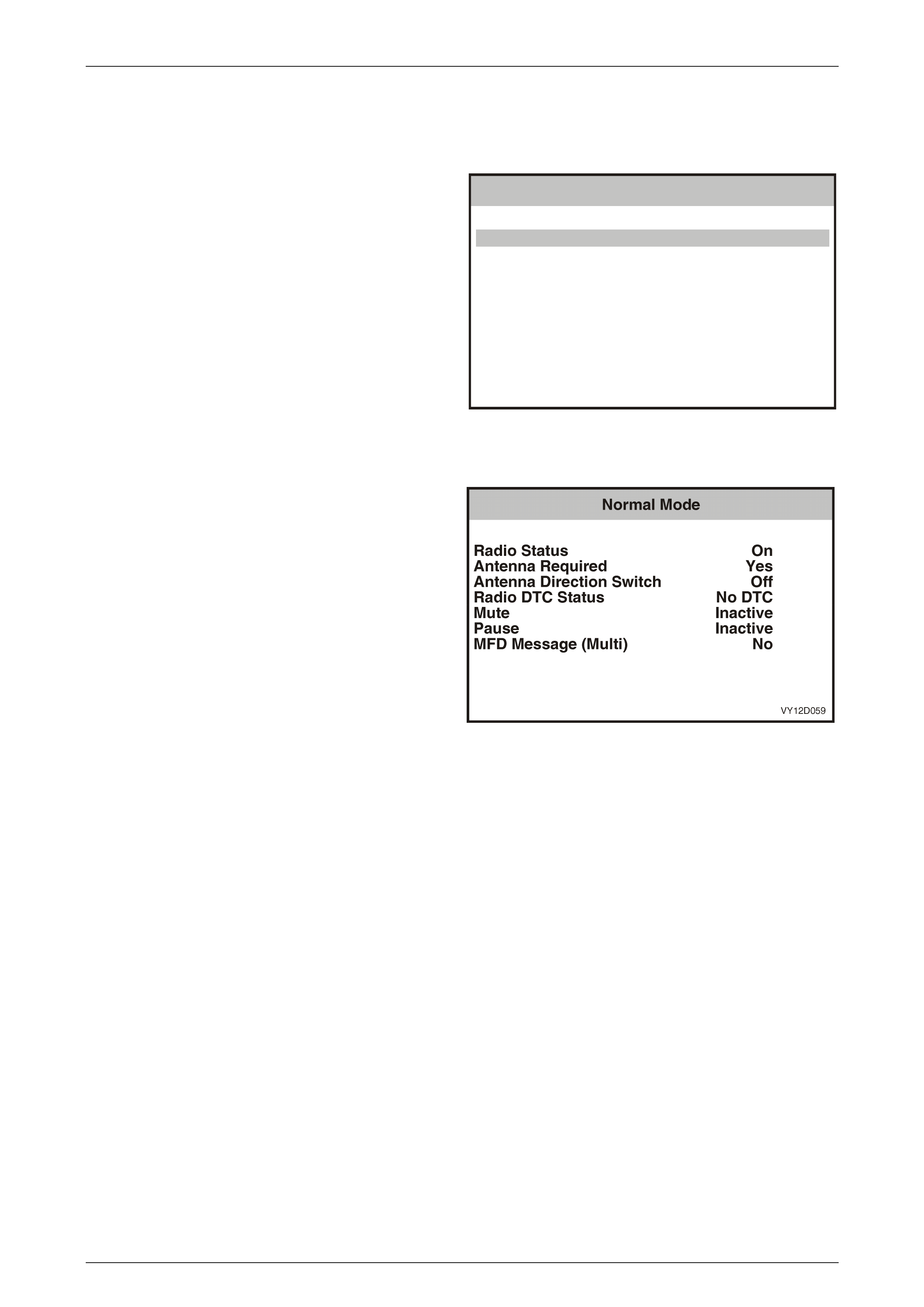
Entertainment System Page 12D–83
Page 12D–83
3.6 Normal Mode – Audio System
The Normal Mode data list is used to view serial data being sent from the audio system.
1 From the Body Menu (refer to 3.5 TECH 2 Test Modes
and Display – Audio System Selection in this Section)
select F0: Normal Mode and press the Enter key.
VY12D058
Body
F0:
F1:
F2:
F3:
F4:
F5:
Normal Mode
D iagno stic T rouble C od es
Data Display
Snapshot
M iscellaneous Tests
Program
Figure 12D – 82
F0: Normal Mode
Details of the serial data in the normal mode data list are
provided in the following table.
Figure 12D – 83

Entertainment System Page 12D–84
Page 12D–84
Normal Mode Data List
TECH 2 Displa y Range Remarks
Radio Status On / Off When the audio system head unit is turned off, power is still
applied to the unit to maintain serial data bus communications.
Antenna Required Yes / No
(Yes = Antenna Required
No = Antenna Not Required)
Yes when radio is in AM or FM mode. Voltage is within 0.5 V of
battery voltage when active.
Antenna Direction
Switch Off / Down / Up Active when the antenna up or down button is pressed on
models with electric height adjustable antenna.
Radio DTC Status No DTC / DTCs Set Displays DTCs set when a fault has been detected by the
audio system.
Mute Active / Inactive Active when the radio, CD or DVD is muted.
Pause Active / Inactive Active when the CD is paused.
MFD Message
(Multi Function
Display)
Yes / No
(Yes = Module Response With
Message
No = Normal Module Response)
Yes when data is being sent to the instrument cluster
multi-function display (MFD).
Voice In Active / Inactive Active when a Mobile Phone (or Telematics) is connected to
the Audio System and a call is in progress.
DVD Requested Yes / No Condition is Yes when DVD mo de is selected.
Amplifier Requested Yes / No Condition is Yes when the Audio System is on.
Headphones in use Yes / No Condition is Yes when the rear seat headphones are plugged
in and enabled.
Amplifier DDL
Requested Yes / No Condition is Yes when DDL is enabled.
Rear Roof Remote Locked / Unlocked Condition is Locked when the rear roof remote is locked by the
audio head unit, refer to 1.5 Rear Remote Control in this
Section.
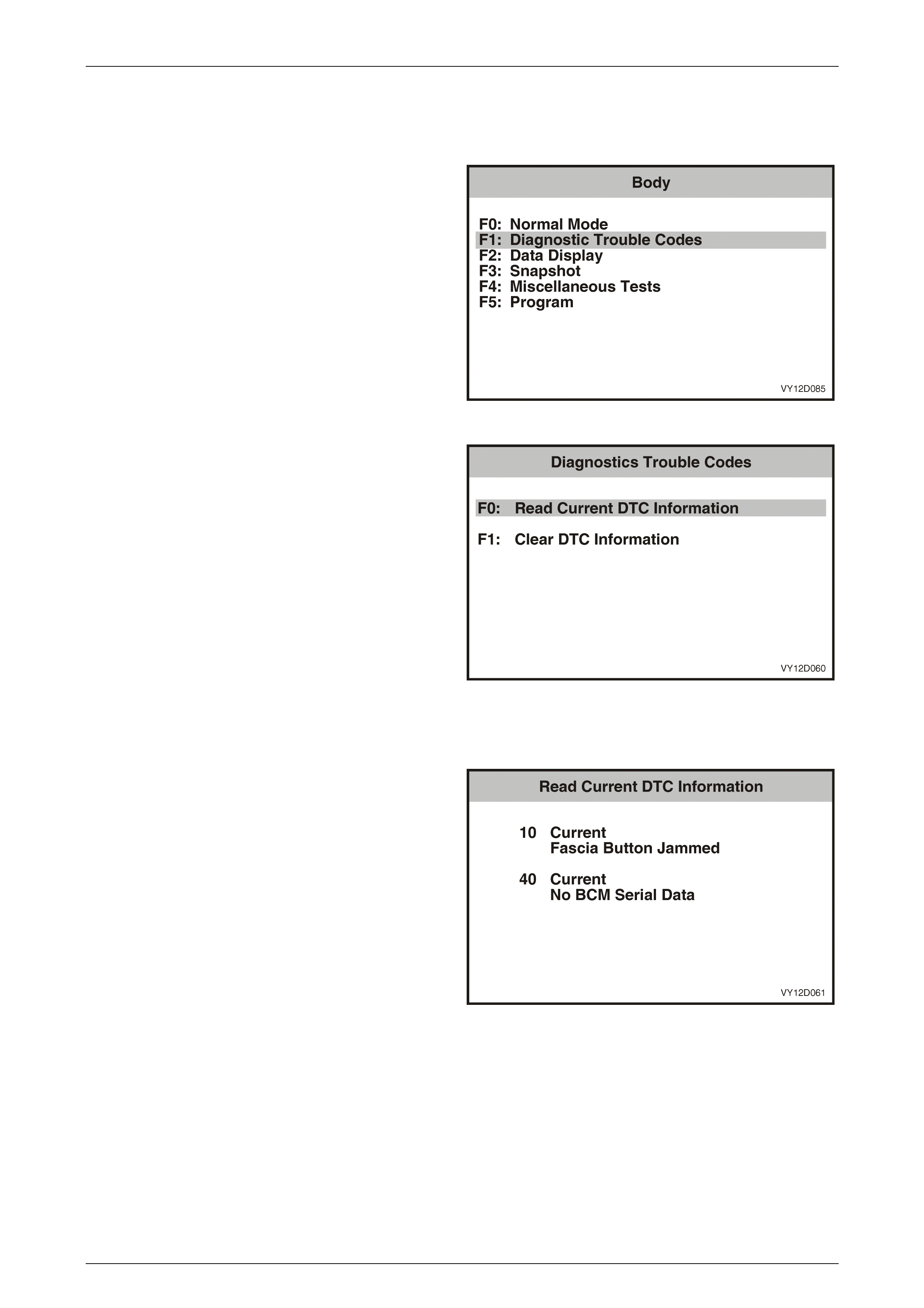
Entertainment System Page 12D–85
Page 12D–85
3.7 Diagnostic Trouble Codes – Audio
System
1 From the Body Menu select F1: Diagnostic Trouble
Codes and press the Enter key.
Figure 12D – 84
2 Using the TECH 2 Up and Down arrows, select the
required item and then press the Enter key.
F0: Read Current DTC Information. If this mode is
selected, a listing of all (if any) DTC that have been set by
the audio system will be displayed.
F1: Clear DTC Information. DTC can be cleared in this
mode by simply selecting F1: Clear DTC Information,
pressing the Enter key on TECH 2 and confirming the action
as instructed by TECH 2.
NOTE
TECH 2 will display Clear DTC Information, or
Failed if any DTCs are still current.
Figure 12D – 85
Read Current DTC Inf orma tion
If any DTCs are set, reference should be made to the
relevant diagnostic charts in this Section.
NOTE
This illustration shows and example of two DTCs
and their status, i.e. Current. The following table
identifies DTCs applicable to the Audio System.
Figure 12D – 86

Entertainment System Page 12D–86
Page 12D–86
A udio System Diagnostic Trouble Code List
DTC 10 Fascia Button Jammed DTC 30 Internal Bus Failure
DTC 11 Steering Wheel Remote Button Jammed DTC 33 Single Communication Bus Failure
DTC 12 Reserved DTC 34 Multi Co mmunicatio n Bus Failure
DTC 21 CD Mechanism Error DTC 35 Fascia Communication Bus Failure
DTC 22 CD Play Error DTC 36 DSP Failure
DTC 24 CD Loading Error DTC 40 No BCM Serial Data
DTC 25 CD Defect DTC 41 No UART2 Serial Data
DTC 26 CD General Error DTC 42 Reserved
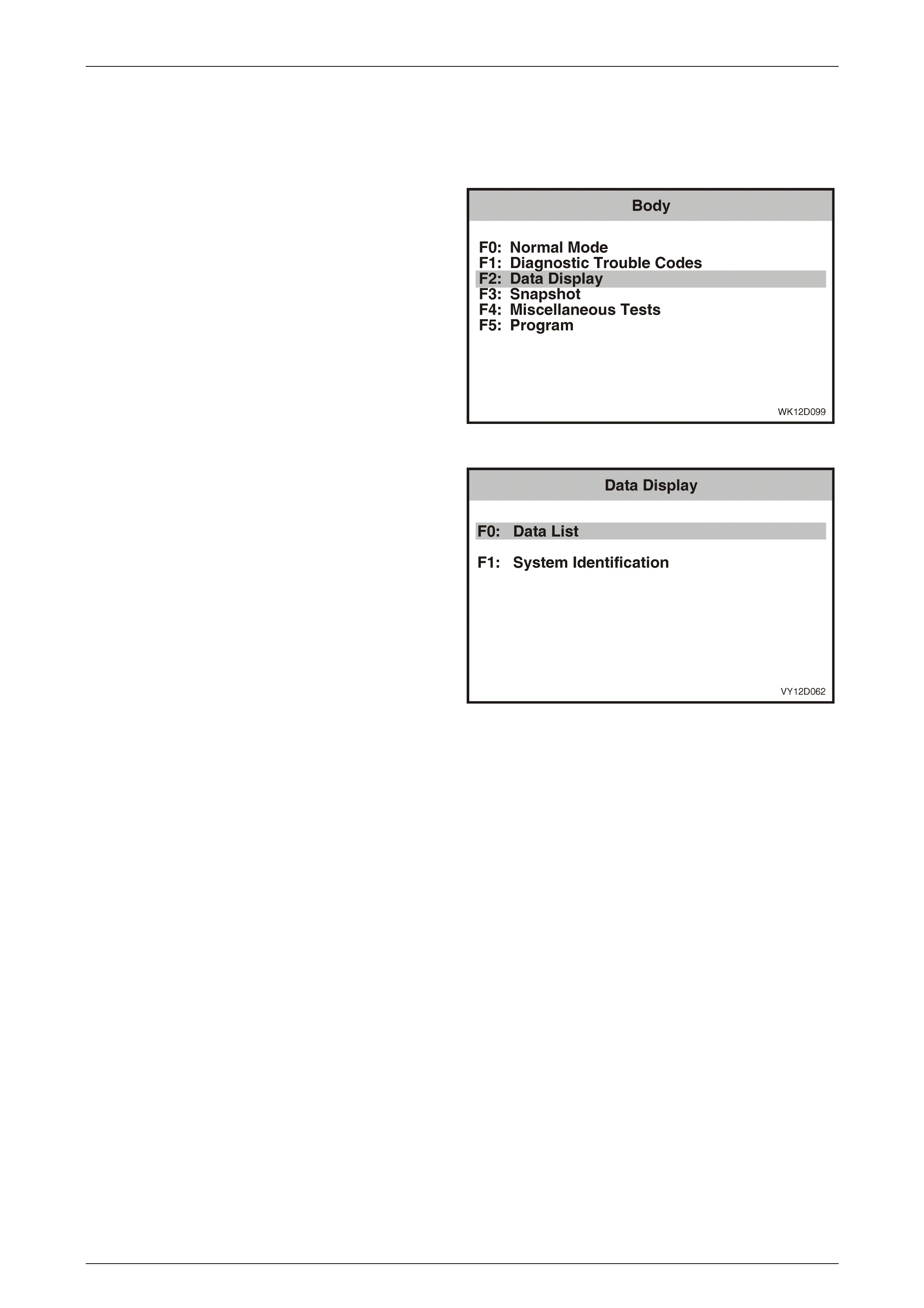
Entertainment System Page 12D–87
Page 12D–87
3.8 Diagnostic Data Display – Audio System
The Diagnostic Data Display function allows the status of the audio system inputs and outputs to be monitored, as well
as the system identification details.
1 From the Body Menu select Data Display and press
the Enter key.
Figure 12D – 87
2 Using the TECH 2 Up and Down arrows, select the
required item and then press the Enter key.
F0: Data List. If this mode is selected, a listing of all serial
data being sent by the audio system will be displayed.
F1: System Information. Provides details of system
identification.
Figure 12D – 88
F0: Data List
The serial data from the audio system can be checked and tested by selecting the item and pressing the Select Items
soft key. The list can be scrolled by using the Up and Down arrow keys.
NOTE
Only the data relevant to the level of audio
system installed will be displayed.

Entertainment System Page 12D–88
Page 12D–88
Data Display Data List
TECH 2 Displa y Range Remarks
Ignition Status On / Off Ignition switch status at terminal X1-A4.
Displays ON when ignition is on.
Security Wait Time Active / Inactive Security lockout timer status. Displays
ACTIVE when an incorrect PIN Code has
been entered.
Audio System Linked to BCM Linked / Unlinked Status of Autocoding system. Shows
LINKED when the radio has been linked
to the vehicle.
Radio Status On / Off Displays audio system status.
Key Priority Signal 1 / 2 Current key setting in use by the audio
system. Setting is tran sm itted by BCM.
Antenna Up Required / Not Required Within 0.5 V of battery voltage when in
AM or FM mode, and 0 V in CD mode.
Antenna Main / Diversity Front or rear antenna selected (if fitted).
Antenna Signal Strength 0 to 100 Signal strength of received station.
100 = very strong signal.
Frequency AM and FM Frequency Range Displays the frequency of the current
station.
Frequency Unit AM = kHz / FM = MHz Displays the frequency of the current
radio mode.
Volume 0 to 63 Volume level set by the volume knob or
remote control.
Speed Dependent Volume Control 0 to 20 Amount of additional volume added due
to the vehicle speed. Speed is taken
from the serial bus.
Speed Volume Curve 0 to 5 Speed dependent volume compensation
curve selected in the Instrument Cluster
Customisation Mode (Options Menu).
Mute Control Input Active / Inactive Sound is muted by MUTE button on
steering wheel.
Park Lamp Switch On / Off Status of park lamp input. Displays ON
when park lamps are on.
Preset 1 to 6 Current radio Memory Preset selection.
0 = no preset selected.
Radio Band FM1, FM2, FM ASM, AM, A M ASM Current radio band and mode selection.
Search Sensitivity DX / LO Station searching sensitivity selection. DX
= Distant Stations, LO = Local Stations.
Stereo Status Mono / Intermediate / Full Stereo Displays the current FM stereo status.
Setting depends on antenna signal
st rength , multipath and other factors.
Bass –6 to +6 Current Bass setting, adjusted with the
audio knob. –6 = Minimum, STD =
Standard Setting, +6 = Maximum
Treble –6 to +6 Current Treble setting, adjusted with the
audio knob. –6 = Minimum, STD =
Standard Setting, +6 = Maximum
Balance –6 to +6 Current Balance setting, adj ust ed with the
audio knob. L6 = Maximum Left, STD =
Standard Setting, R6 = Maximum Right

Entertainment System Page 12D–89
Page 12D–89
TECH 2 Displa y Range Remarks
Fader –6 to +6 Current Fader setting, adjusted with the
audio knob. R6 = Maximum Rear, STD =
Standard Setting, F6 = Maximum Front
Loudness Bass Boost –6 to +6 Amount of Bass added by the Loudness
function. Reduces to 0 as the volume is
increased. –6 = Minimum, STD =
Standard Setting, +6 = Maximum
Loudness Treble Boost –6 to +6 Amount of Treble added by the Loudness
function. Reduces to 0 as the volume is
increased. –6 = Minimum, STD =
Standard Setting, +6 = Maximum
Equaliser Off, Rock, Pop, Jazz, Classical, Vocal Displays the Equaliser Mode that is
currently active.
Equaliser Boost Off, –2 to +2 Displays the current Boost selection.
Digital Signal Processor Off, Concert Hall, Cathedral, Stadium,
Club, Theatre Displays the current DSP selection.
Delay -3 to +3 Displays the amount of delay added by
the delay function.
Echo -3 to +3 Displays the amount of echo added by
the echo function.
Position Off, Driver, Passenger, Front, All Displays the current listening position
selection.
Audio Source Tuner, CD, External Source Displays the current audio source
selection.
Fascia Button Button Name / Key Released Displays the name of the audio system
head unit fascia button when that button
is pressed, or Key Released if no button
is pressed.
Steer ing Wheel Remote Co ntrol But ton Name / Key Released Displays the name of the steering wh eel
remote control button when that button is
pressed, or Key Released if no button is
pressed.
Rear Remote Control Button Name / Key Released Displays the name of the rear remote
control button when that button is
pressed, or Key Released if no button is
pressed.
CD In Yes / No Indicates if a CD is currently in the
mechanism or not.
Current CD None, 1 to 6 Displays the number of the CD in the CD
Changer currently being played.
Current Track 0 to 99 Displays the current CD track being
played. Number displayed depends on
the number of tracks on the disc. 0 = no
track selected.
CD Mode Track Random, Track Repeat, Track
Scan, Disc Random, Disc Repeat, Disc
Scan, Play, Pause
Displays the current CD playing mode.

Entertainment System Page 12D–90
Page 12D–90
F1: System Identification
The System Identification screen provides production
information relevant to the Audio System.
The identifier number defines the Audio System installed.
The details are:
• 000 – Unidentified.
• 102 – VY System 1G; Chevrolet Caprice LS.
• 306 – VY System 3B; Chevrolet Caprice LS.
• 311 – System 3A; Chevrolet Caprice LTZ,
Chevrolet Caprice SS.
• 411 – System 4; Holden Statesman.
• 601 – System 6; Holden Caprice, Chevrolet
Caprice (Royale).
Figure 12D – 89
Figure 12D – 90
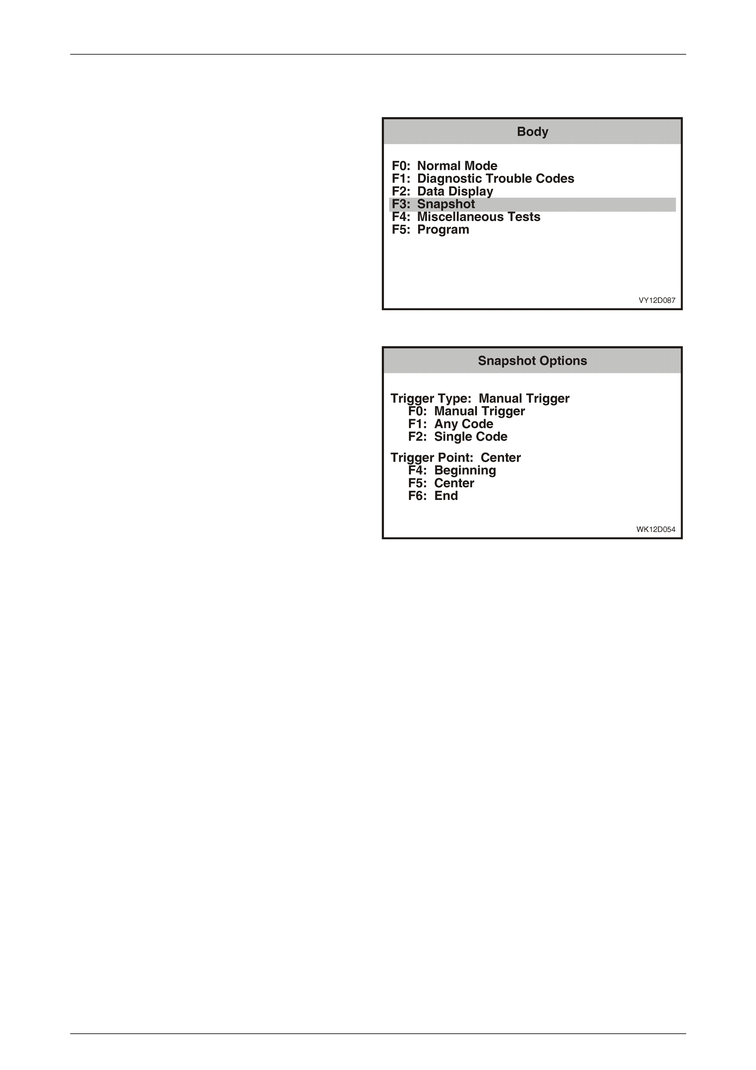
Entertainment System Page 12D–91
Page 12D–91
3.9 Snapshot – Audio System
1 From the Body Menu select F3: Snapshot and press
the Enter key.
Figure 12D – 91
The TECH 2 can be used to record system information that
is occurring at a particular moment in time, and this is called
a snapshot. For more details, refer to the TECH 2 User's
Guide.
Figure 12D – 92
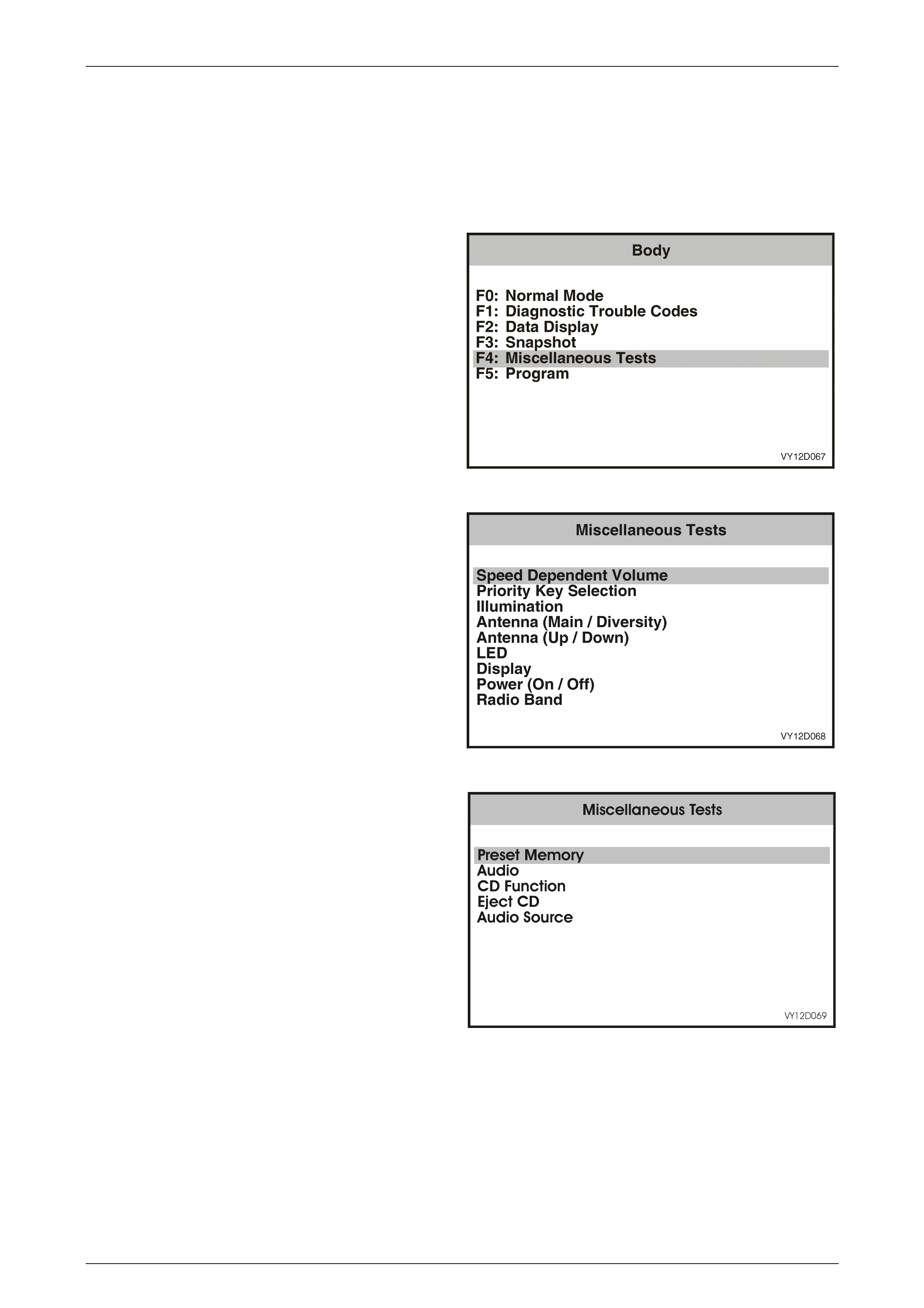
Entertainment System Page 12D–92
Page 12D–92
3.10 Miscellaneous Tests – Audio System
The TECH 2 can be used to verify correct operation of the various functions of the audio system to assist in isolating a
fault condition. The TECH 2 can be used to force various functions on or off and monitors the response.
Note that if any test takes longer than 40 seconds to perform, the audio system will time-out and the test may have to be
started again.
1 From the Body Menu select F4: Miscellaneous Tests
and press the Enter key.
Figure 12D – 93
2 Scroll through the Miscellaneous Tests using the
TECH 2 Up and Down arrows. To select the required
test, press the Enter key.
NOTE
Only the Miscellaneous Tests relevant to the
level of audio system installed will be displayed.
Figure 12D – 94
Figure 12D – 95
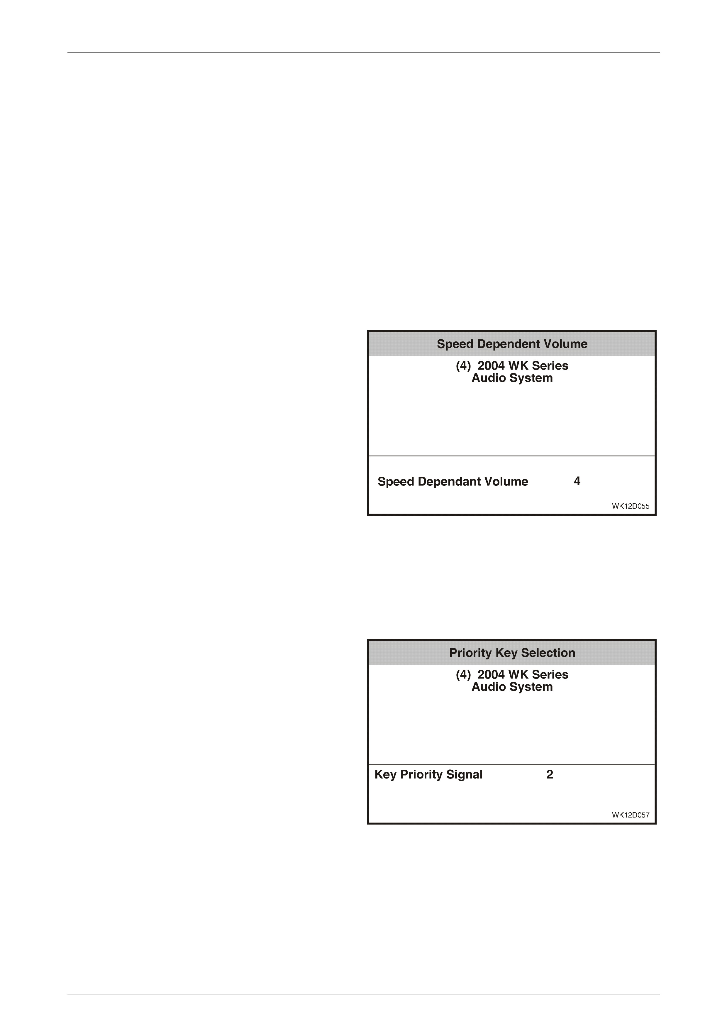
Entertainment System Page 12D–93
Page 12D–93
Speed Dependent Volume
The Speed Dependent Volume test is performed using TECH 2, and allows the input of simulated road speeds to verify
the correct operation of the speed dependent volume function.
1 Turn the radio off.
2 To enter the audio system Options Menu, press and
hold the Preset Station 1 button while turning the radio
on.
3 Press the audio button to advance to the speed
dependent volume screen, and then rotate the volume
knob to choose a setting of 2 or higher (note that 0 =
function off).
4 Turn the radio off then back on again to save the new
setting.
5 Select a strong local radio station frequency and set
the volume to a comfortable listening level.
6. Connect the TECH 2 to the DLC. Select Body / Audio
System / Miscellaneous Tests / Speed Dependent
Volume.
7. Press the Increase soft key on the TECH 2 to simulate
and increase in road speed. Listen for an increase in
volume.
8. Press the Decrease soft key on the TECH 2 and listen
for return to normal volume.
9. Press the Quit soft key to exit the test. The speed
dependent volume will be set to the standard setting
(2) on exiting the test.
10. If the speed dependent volume function does not
operate correctly, replace the audio system head unit.
Refer to 2.1 Audio System Head Unit in this Section.
Figure 12D – 96
Priority Key Selection
The Priority Key Selection test is performed using TECH 2, and checks for correct switching between the Priority Key 1
audio system settings and the Priority Key 2 settings. Note that when the priority key selection is made at the TECH 2,
the audio system responds to the change then reverts back to the selection corresponding to the key in the ignition.
1 Connect the TECH 2 to the DLC. Select Body / Audio
System / Miscellaneous Tests / Priority Key Selection.
2 Switch the audio system on.
3 The TECH 2 will display the current serial data at the
top of the screen, and the Key Priority Signal and
associated key number at the bottom of the screen.
4 Press the Priority 1 soft key on the TECH 2 and check
that the audio system switches to the Priority Key 1
settings. Verify that the TECH 2 screen reflects the
selection of Priority Key 1.
5 Press the Priority 2 soft key on the TECH 2 and check
that the audio system switches to the Priority Key 2
settings. Verify that the TECH 2 screen reflects the
selection of Priority Key 2.
6 Press the Quit soft key to exit the test.
7 If the Priority Key Selection function does not operate
correctly, replace the audio system head unit. Refer to
2.1 Audio System Head Unit in this Section.
Figure 12D – 97

Entertainment System Page 12D–94
Page 12D–94
Illumination
The audio system buttons and LCD (Level 1 only) are fully illuminated. The audio head unit receives the illumination
control signal from the hardwired illumination input on the connector. The actual dimming value is received from the BCM
by serial data.
The fascia Illumination test is performed using TECH 2, and controls the fascia illumination directly to verify correct
operation.
1 Turn the park lamps on.
2 Connect the TECH 2 to the DLC. Select Body / Audio System / Miscellaneous Tests / Illumination.
3 Turn the radio on.
4 Using the Increase soft key on the TECH 2, increase the illumination level to maximum.
5 Check that the display illumination is even with no dark patches. Also check that the fascia control buttons are
illuminated.
6 Using the Decrease soft key on the TECH 2, decrease the illumination level and check that the fascia illumination
decreases accordingly.
7 Press the Quit soft key to exit the test. The standard illumination level will be selected on exiting the test.
8 If the Illumination function does not operate correctly, replace the audio system head unit. Refer to 2.1 Audio
System Head Unit in this Section.
Antenna Selection
Some models are fitted with a dual antenna system, called Main and Diversity antennas respectively. When testing the
antenna systems it is useful to command to the audio head unit which antenna to use when making comparisons in
signal quality between the two systems. The Antenna Selection test is performed using TECH 2.
1 Connect TECH 2 to the DLC. Select Diagnostics / Model Year / Vehicle Model / Body / Audio System /
Miscellaneous Tests / Antenna (Main / Diversity).
2 Switch the audio system on and select a strong local FM radio station frequency. Set the volume to a comfortable
listening level.
3 Use the Main soft key on the TECH 2 to select the main antenna. Verify that the TECH 2 screen reflects the
appropriate antenna selection.
4 From the Body Menu select Data Display / Data List, then use the Down arrow key on the TECH 2 to scroll to
Antenna and verify that the Main antenna is selected.
5 Use the Down arrow key on the TECH 2 to scroll to Antenna Signal Strength and note the signal strength
indication.
6 From the Body Menu select Miscellaneous Tests / Antenna (Main / Diversity).
7 Use the Diversity soft key on the TECH 2 to select the diversity antenna. Verify that the TECH 2 screen reflects the
appropriate antenna selection.
8 From the Body Menu select Data Display / Data List, then use the Down arrow key on the TECH 2 to scroll to
Antenna and verify that the Diversity antenna is selected.
9 Use the Down arrow key on the TECH 2 to scroll to Antenna Signal Strength and note the signal strength
indication.
10 Compare signal strength figures to provide an objective comparison of antenna performance.
11 Press the Quit soft key to exit the test. The Main antenna will be selected on exiting the test.
12 If the Antenna Selection function does not operate correctly, replace the audio system head unit. Refer to 2.1 Audio
System Head Unit in this Section.
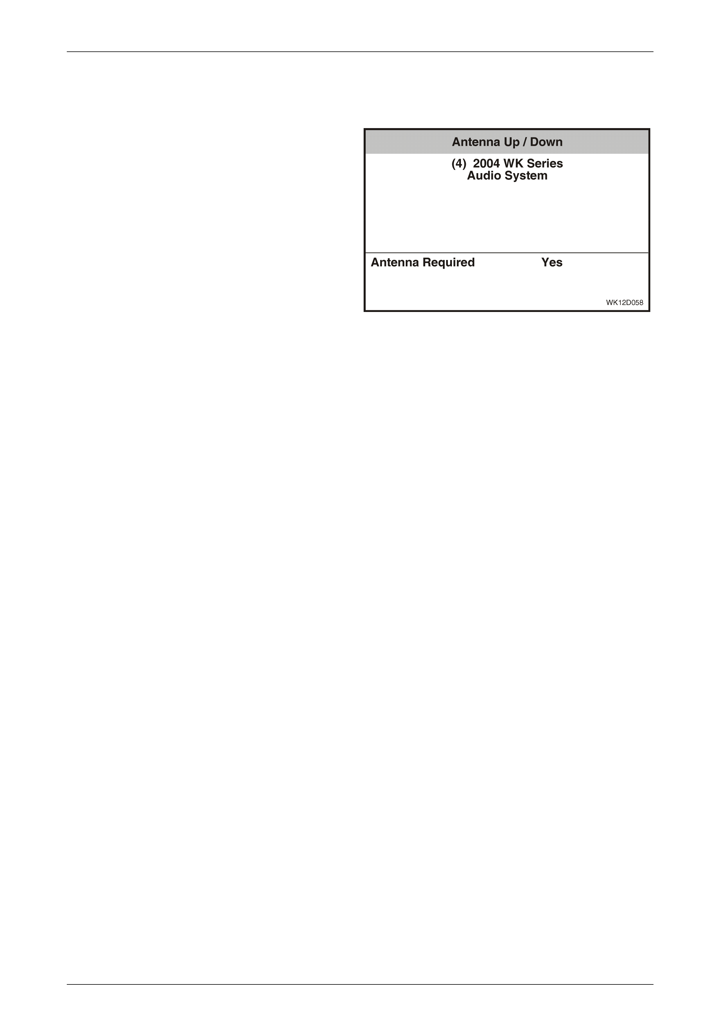
Entertainment System Page 12D–95
Page 12D–95
Antenna ( Up / Down)
The Antenna (Up / Down) test is performed using TECH 2, and directly controls the Main antenna by driving it up or
down.
1 Connect TECH 2 to the DLC. Select Diagnostics /
Model Year / Vehicle Model / Body / Audio System /
Miscellaneous Tests / Antenna (Up / Down).
2 Ensure that the ignition is on, and turn the radio on.
3 The TECH 2 will display the current antenna status at
the bottom of the screen.
4 Using the Up soft key on the TECH 2, drive the
antenna up. Verify correct antenna operation, and that
this status is reflected on the TECH 2 screen.
5 Using the Down soft key on the TECH 2, drive the
antenna down. Verify correct antenna operation, and
that this status is reflected on the TECH 2 screen.
6 Press the Quit soft key to exit the test. The Main
antenna will be left in the last test position upon exiting
the test.
7 If the Antenna (Up / Down) function does not operate
correctly, replace the audio system head unit. Refer to
2.1 Audio System Head Unit in this Section.
Figure 12D – 98
Security LED
The LED on the top left of the audio head unit fascia is used as a security indicator and to show the status of the
CD/CDC loading and ejecting. This test is performed using TECH 2, and directly controls the LED to verify correct
operation.
1 Connect TECH 2 to the DLC. Select Diagnostics / Model Year / Vehicle Model / Body / Audio System /
Miscellaneous Tests / LED.
2 Ensure that the ignition is on, and turn the radio off.
3 Press the On soft key on the TECH 2, and verify that the LED illuminates (orange). If LED illuminates green or red,
this indicates a fault and the audio sy ste m head unit should be replaced.
4 Press the Off soft key on the TECH 2 and verify that the LED extinguishes.
5 Press the Quit soft key to exit the test. The LED will extinguish upon exiting the test.
6 If the LED test function does not operate correctly, replace the audio system head unit. Refer to 2.1 Audio System
Head Unit in this Section.
Display
The Level 1 audio system incorporates a large dot-matrix type display. The Level 2 to 5 Audio Systems output audio
information to the MFD. This test is performed using the TECH 2, and directly controls all segments on the AHU display
(Level 1 vehicles) or MFD display (Levels 2 to 5 vehicles) to verify correct operation.
1 Connect TECH 2 to the DLC. Select Diagnostics / Model Year / Vehicle Model / Body / Audio System /
Miscellaneous Tests / Display.
2 Ensure that the ignition is on, and switch the audio system on.
3 Press the On soft key on the TECH 2 and verify that all display segments are illuminated (lower half of MFD for
Level 2 to 5 vehicles).
4 Press the Off soft key on the TECH 2 and verify that all display segments extinguish (lower half of MFD for Level 2
to 5 vehicles).
5 Press the Quit soft key to exit the test.
6 Switch the audio system off then on again to reset the display.
7 If the display test function does not operate correctly for the Level 1 audio system, replace the audio system head
unit. Refer to 2.1 Audio System Head Unit in this Section. If the display test function does not operate correctly for
the Level 2 to 5 audio systems, refer to Section 12I, 3.8 Multi Function Display Diagnostic Procedures in this
Service Information for further diagnosis.
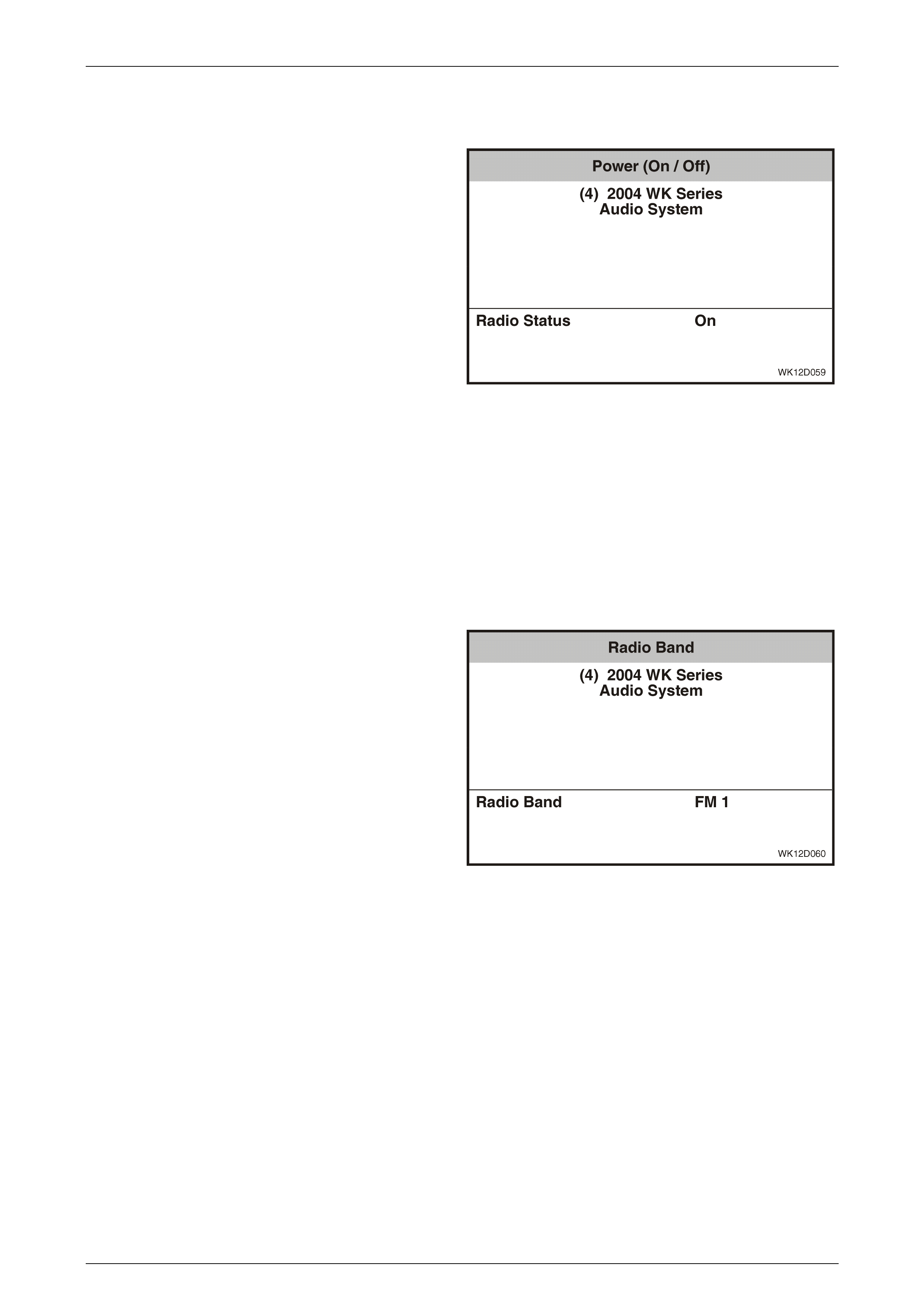
Entertainment System Page 12D–96
Page 12D–96
Po wer ( On / Off)
This test is performed using the TECH 2, and verifies that the audio system head unit switches on or off correctly.
1 Connect TECH 2 to the DLC. Select Diagnostics /
Model Year / Vehicle Model / Body / Audio System /
Miscellaneous Tests / Power (On / Off).
2 Ensure that the ignition is on, and switch the audio
system off.
3 The TECH 2 will display the current radio status at the
bottom of the screen.
4 Press the On soft key on the TECH 2 and verify that
the audio system switches on, and that this status is
reflected on the TECH 2 screen.
5 Press the Off soft key on the TECH 2 and verify that
the audio system switches off, and that this status is
reflected on the TECH 2 screen.
6 Press the Quit soft key to exit the test. The audio
system will be left in the last test position upon exiting
the test.
7 If the Power (On / Off) function does not operate
correctly, replace the audio system head unit. Refer
to 2.1 Audio System Head Unit in this Section.
Figure 12D – 99
Radio Band
This test is performed using the TECH 2, and verifies that the audio system head unit switches correctly between the AM
and the FM bands.
1 Connect TECH 2 to the DLC. Select Diagnostics /
Model Year / Vehicle Model / Body / Audio System /
Miscellaneous Tests / Radio Band.
2 Ensure that the ignition is on, and switch the audio
system on.
3 The TECH 2 will display the current radio band status
at the bottom of the screen.
4 Using the AM and FM soft keys on the TECH 2, switch
between the two radio bands and verify that the audio
system switches radio bands as follows:
• AM selects AM Preset 1.
• FM selects FM1 Preset 1.
Verify that the selected band is reflected on the
TECH 2 screen.
5 Press the Quit soft key to exit the test. The audio
system head unit will be left in the last test position
upon exiting the test.
6 If the Radio Band function does not operate correctly,
replace the audio system head unit. Refer to
2.1 Audio System Head Unit in this Section.
Figure 12D – 100
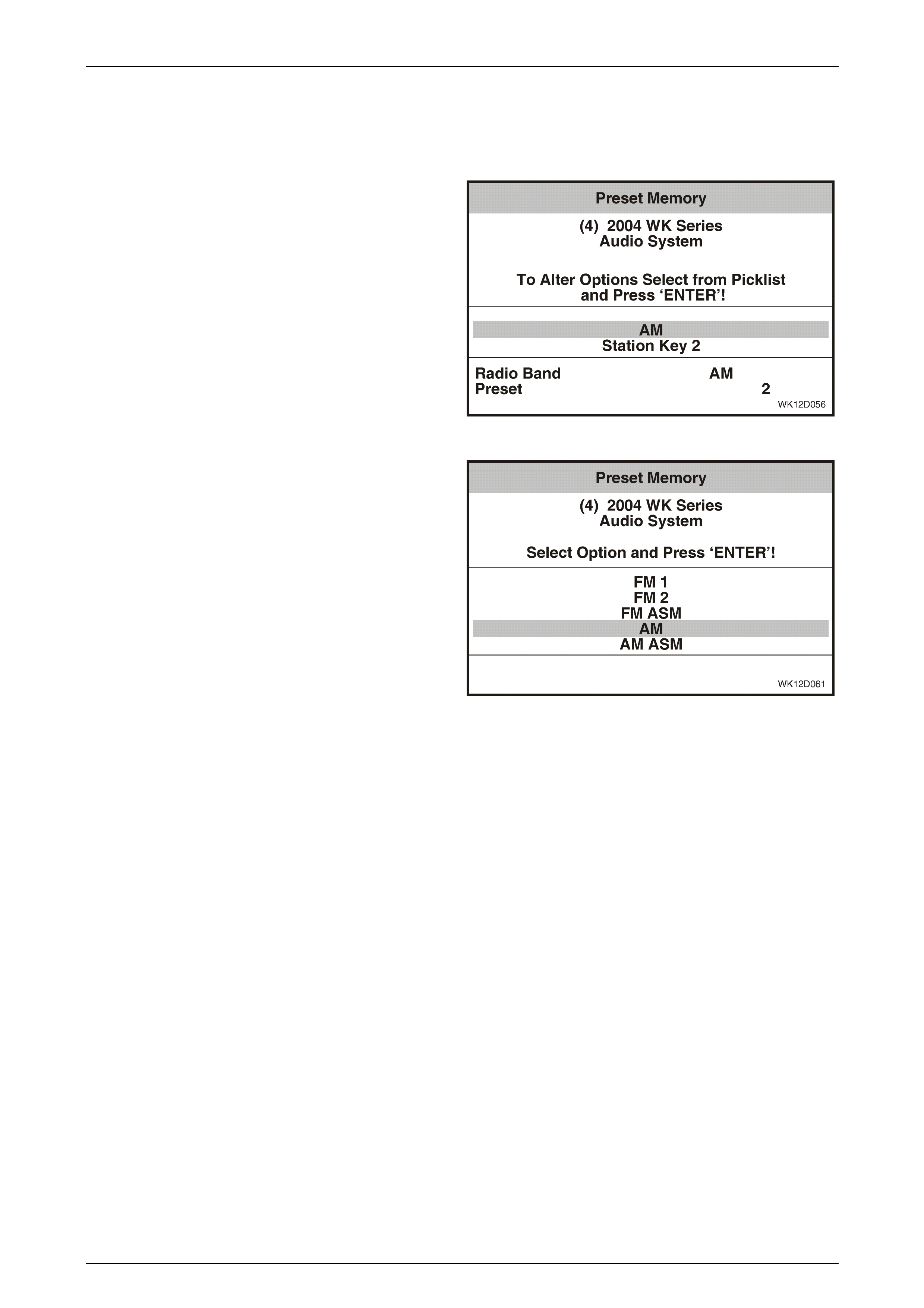
Entertainment System Page 12D–97
Page 12D–97
Preset Memory
This test is performed using the TECH 2, and verifies that the audio system head unit selects each of the currently stored
preset stations correctly for both the AM and the FM bands. The AM band has two preset bands (AM and AM ASM),
while the FM band has three (FM1, FM2 and FM ASM), with each band having six preset stations.
1 Connect TECH 2 to the DLC. Select Body / Audio
System / Miscellaneous Tests / Preset Memory.
2 Ensure that the ignition is on, and the audio system is
on.
3 The TECH 2 screen displays the current preset band
and current statio n.
4 Use the TECH 2 Up and Down arrows to select from
the list and press Enter or Modify.
Figure 12D – 101
5 Use the TECH 2 Up and Down arrows to scroll to the
option required.
6 Use the Okay soft key to enable the selection, or the
Back soft key to return to the previous screen.
7 Press the Program soft key to program the preset and
check that the radio changes to the selected preset.
8 Press the Quit soft key to exit the test. The audio
system presets will be left in the last test position upon
exiting the test.
9 If the Preset Memory function does not operate
correctly, replace the audio system head unit. Refer to
2.1 Audio System Head Unit in this Section.
Figure 12D – 102
Audio
This test is performed using the TECH 2, and verifies that the audio system head unit speaker output signals are
operating correctly. The Audio test checks the Treble and Bass outputs to each speaker.
NOTE
Only the speaker configuration fitted for the
vehicle will appear in the following test.
1 Connect TECH 2 to the DLC. Select Diagnostics / Model Year / Vehicle Model / Body / Audio System /
Miscellaneous Tests / Audio.
2 Ensure that the ignition is on. Switch the audio system on and choose a strong local radio station frequency.
3 Turn EQ off if this feature is available on the audio head unit.
4 Manually adjust the volume level as requested by TECH 2 and press the Confirm soft key.
5 The right rear speaker will be selected for testing. Using the Increase and Decrease soft keys, vary the bass setting
from –6 to +6 and listen for the variation.
6 Use the TECH 2 soft keys to select the other speakers and repeat the test.
7 Repeat Steps 4 and 5 for the Treble Test.
8 Press the Quit soft key to exit the test.
9 If the Audio test function does not operate correctly, replace the audio system head unit. Refer to 2.1 Audio System
Head Unit in this Section.
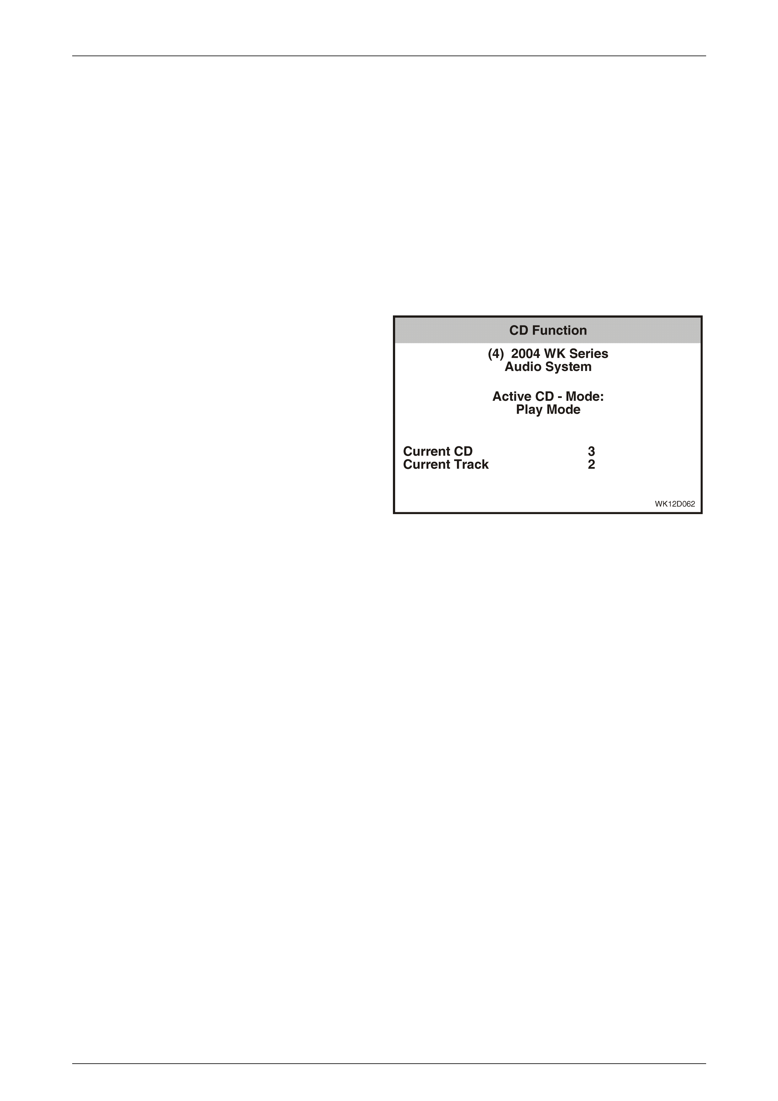
Entertainment System Page 12D–98
Page 12D–98
CD Function
This test is performed using the TECH 2, and verifies that the CD changes correctly between the various operating
modes.
The Next CD Mode soft key on the TECH 2 is used to step through this test. If the Previous CD Mode soft key is used
the TECH 2 will command the modes in the reverse order.
1 Connect TECH 2 to the DLC. Select Diagnostics /
Model Year / Vehicle Model / Body / Audio System /
Miscellaneous Tests / CD Function.
2 Ensure that the ignition is on and switch the audio
system on. Press the LOAD button on the audio
system fascia and insert a disc, or insert a CD on a
single CD player
3 Press the Next CD Mode soft key to command the CD
to play the installed disc. The current track and CD
number will be shown on TECH 2.
Figure 12D – 103
4 Press the Next CD Mode soft key to command the CD
to change the disc. The current track and CD number
will be shown on TECH 2.
NOTE
On System 1 type audio head units step 4 will be
skipped.
5 Press the Next CD Mode soft key to command the CD
to change to the next track. The current track and CD
number will be shown on TECH 2.
6 Press the Next CD Mode soft key to command the CD
to fast forward the current track. The current track and
CD number will be shown on TECH 2.
7 Press the Next CD Mode soft key to command the CD
to fast rewind the current track. The current track and
CD number will be shown on TECH 2.
8 Press the Next CD Mode soft key to command the CD
to pause the current track. The current track and CD
number will be shown on TECH 2.
9 Press the Quit soft key to exit the test.
10 If the CD function does not operate correctly, replace
the audio system head unit. Refer to 2.1
A
udio System
Head Unit in this Section.
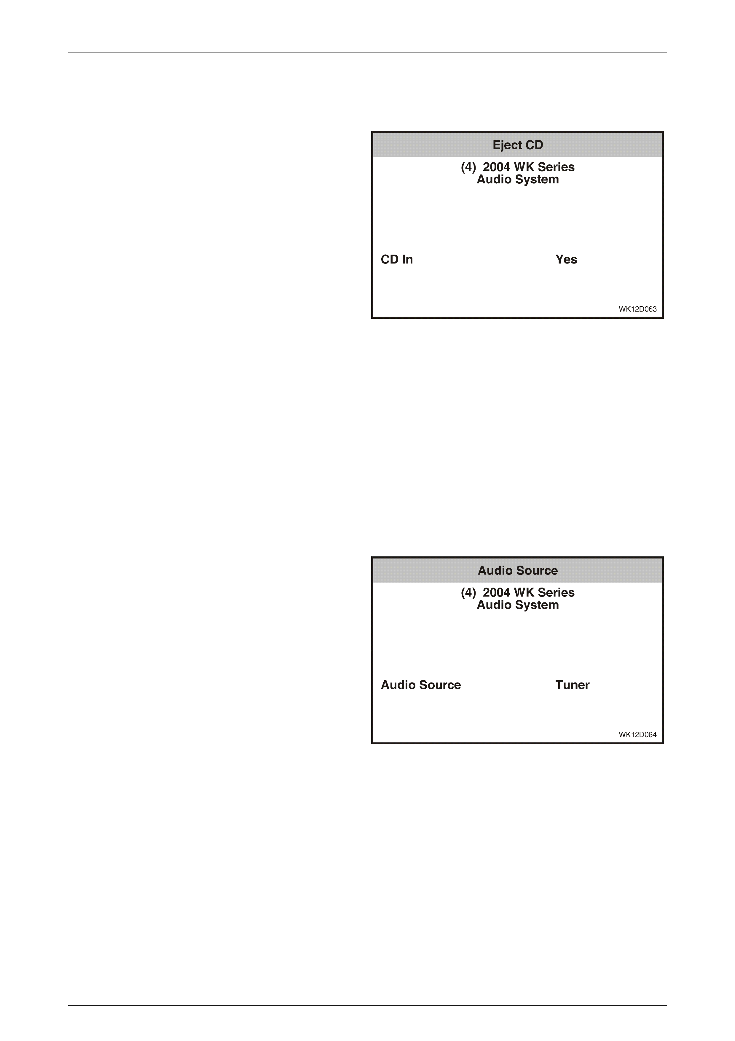
Entertainment System Page 12D–99
Page 12D–99
Eject CD
This test is performed using the TECH 2, and commands the audio system to eject a single CD or multiple CDs. It is
useful when there is a problem with the audio head unit fascia and the EJECT button is not functioning correctly.
1 Connect TECH 2 to the DLC. Select Diagnostics /
Model Year / Vehicle Model / Body / Audio System /
Miscellaneous Tests / Eject CD.
2 Ensure that the ignition is on, and switch the audio
system on.
3 To eject the current CD from a CD Changer, press the
Eject Curr. CD soft key on TECH 2.
Figure 12D – 104
4 To eject a specific CD, press the Eject Spec. CD soft
key on the TECH 2. Enter the CD number then press
the Enter key.
5 Press the Quit soft key to exit the test.
6 If the Eject CD function does not operate correctly,
replace the audio system head unit. Refer to 2.1
A
udio
System Head Unit in this Section.
Audio Source
This test is performed using the TECH 2, and verifies that the audio system head unit will correctly change the audio
source as directed by the fascia control buttons. The audio source can be selected between the radio tuner, the CD or an
external source.
1 Connect the TECH 2 to the DLC. Select Body / Audio
System / Miscellaneous Tests / Audio Source.
2 Ensure that the ignition is on, and switch the audio
system on.
3 Press the Tuner soft key on the TECH 2.
4 Check that the audio head unit radio tuner can be
operated and that the TECH 2 screen displays this
selection.
Figure 12D – 105
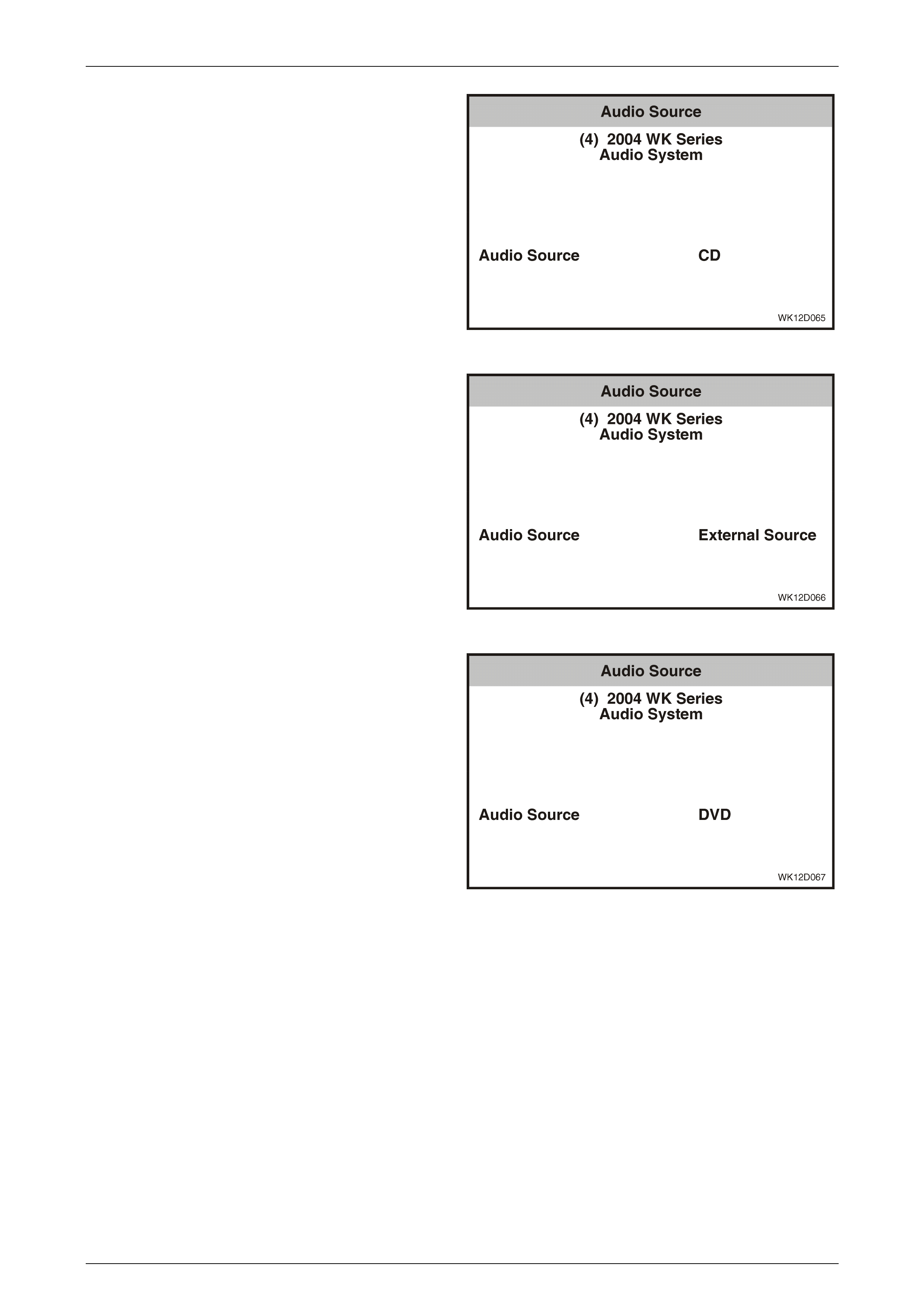
Entertainment System Page 12D–100
Page 12D–100
5 Press the CD soft key on the TECH 2.
6 Check that the audio head unit CD Changer can be
operated and that the TECH 2 screen displays this
selection.
Figure 12D – 106
7 Press the Ext. Source soft key on the TECH 2
8 Check that the audio head unit can be operated from
an external audio source and that the TECH 2 screen
displays this selection.
Figure 12D – 107
9 Press the DVD soft key on the TECH 2.
10 Check that the rear seat entertainment system can be
operated and that the TECH 2 screen displays this
selection.
11 Press the Quit soft key to exit the test. The audio
system audio source selection will be left in the last
test position upon exiting the test.
12 If the Audio Source function does not operate
correctly, replace the audio system head unit. Refer to
2.1 Audio System Head Unit in this Section.
Figure 12D – 108
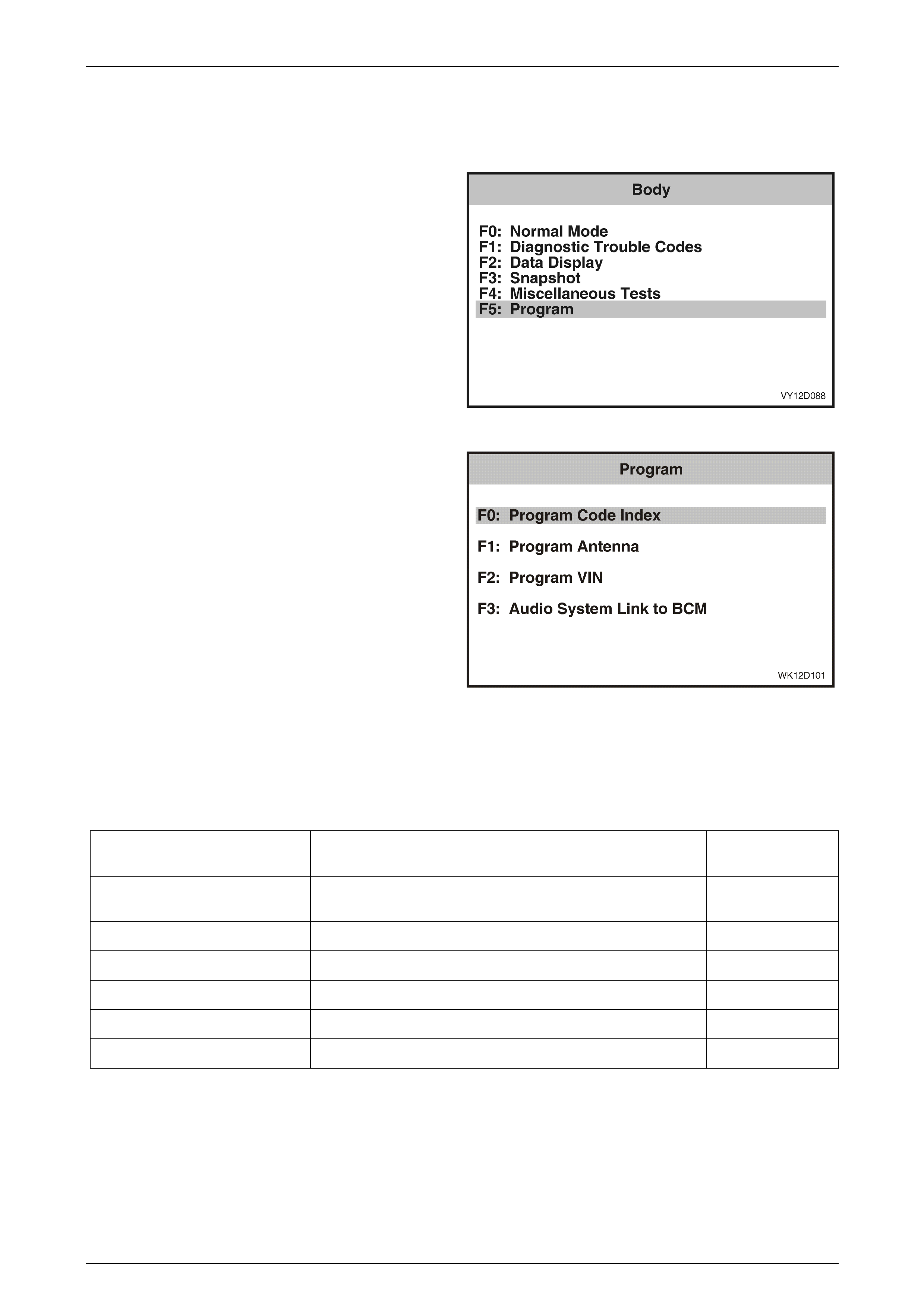
Entertainment System Page 12D–101
Page 12D–101
3.11 Program – Audio System
The Program function allows various Audio System parameters to be programmed.
1 From the Body Menu select F5: Program and press
the Enter key.
Figure 12D – 109
2 Using the TECH 2 Up and Down arrows, select the
required item and then press the Enter key.
Figure 12D – 110
F0: Program Code Index
The Code Index number identifies the audio system and vehicle configuration, and the Code Version number identifies
the software version. Only the Code Index number can be changed. The following table details the Code Index numbers
for the various models in the MY 2004 WK Series vehicles.
Vehicle Audio System
Code Index
Number
Chevrolet Caprice LS (LHD) VY System 1 Gulf States (Standard), VY System 3 Gulf States
(Optional) 008
Chevrolet Caprice LTZ (LHD) WK System 3a Gulf States 013
Chevrolet Caprice SS (LHD) WK System 3a Gulf States 013
Chevrolet Caprice Royale (LHD) WK System 6 Gulf States 015
Holden Statesman WK System 4 014
Holden Caprice WK System 6 014
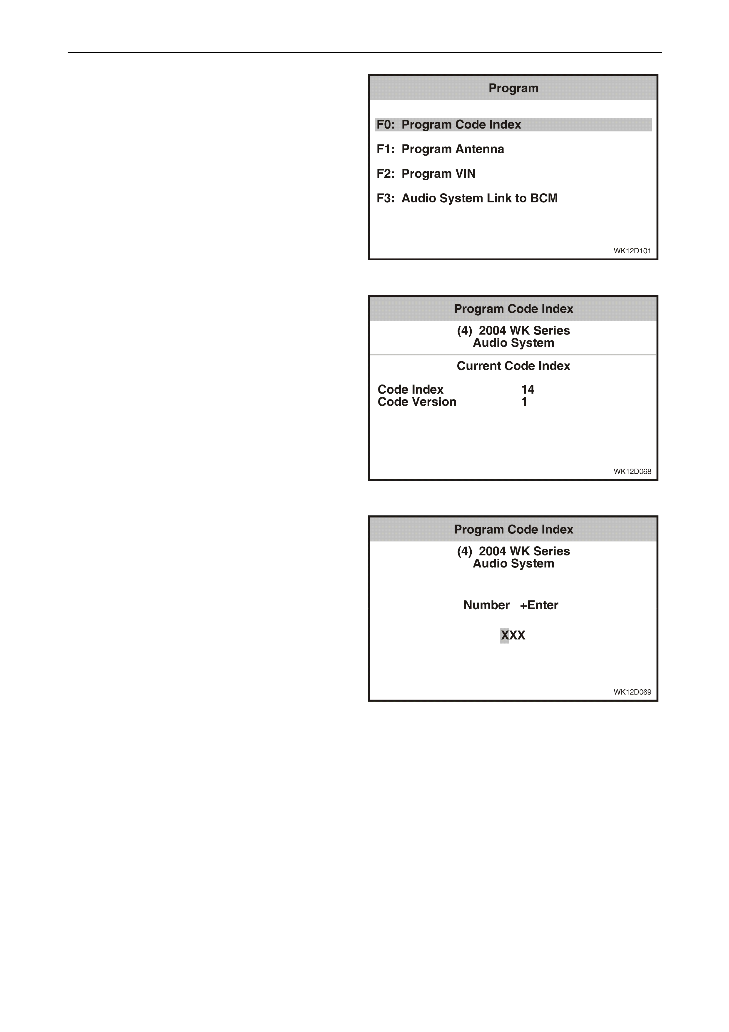
Entertainment System Page 12D–102
Page 12D–102
1 From the Program Menu select F0: Program Code
Index and press the Enter key.
Figure 12D – 111
2 The Code Index number and the Code Version
number are displayed. To change the Code Index
number, press the Program soft key. To exit without
making a change, press the Okay soft key.
Figure 12D – 112
3 Enter the three-digit Code Index number, including
leading zeros, using the numeral keys on TECH 2.
4 Press the Enter key to continue, or the Exit key to exit
without making a change.
5 Follow any TECH 2 screen prompts when
programming is co mple ted.
Figure 12D – 113

Entertainment System Page 12D–103
Page 12D–103
F1: Program Antenna
Audio systems are sup pli ed w ith the antenna drive dis able d
and are enabled on installation. If an antenna drive fails to
operate it may not have been enabled upon installation.
1 From the Program Menu select F1: Program Antenna
and press the Enter key.
Figure 12D – 114
2 Press the Okay soft key on the TECH 2 to enable the
antenna drive.
3 Follow any TECH 2 screen prompts when
programming is co mple ted.
Figure 12D – 115

Entertainment System Page 12D–104
Page 12D–104
3.12 Audio System Diagnostic Procedures
Introduction
The following charts are designed to provide fast and efficient fault location of the audio system. Each diagnostic chart
consists of: a ‘diagnostic chart’ and pertinent information including, where appropriate, Diagnostic Trouble Code (DTC)
setting parameters and circuit diagrams.
When carrying out wiring checks as directed by the diagnostic charts, rather than probe terminals and connectors with
incorrect sized multimeter connections, use the adaptors contained in connector test adaptor kit J35616-A (KM609). This
will prevent any possibility of spreading or damaging wiring harness terminals, which may later cause a system
intermittent failure. Figures 12D – 116 and Figure 12D - 117 illustrate the various connectors associated with the audio
system.
Fuses and relays associated with the audio system are located in the instrument panel fuse and relay panel (refer to
Figure 12D – 118) and engine compartment fuse and relay panel (refer to Figure 12D – 119).
Before commencing any diagnostic procedure, the Diagnostic Circuit Check should be carried out to ensure a known
starting point.
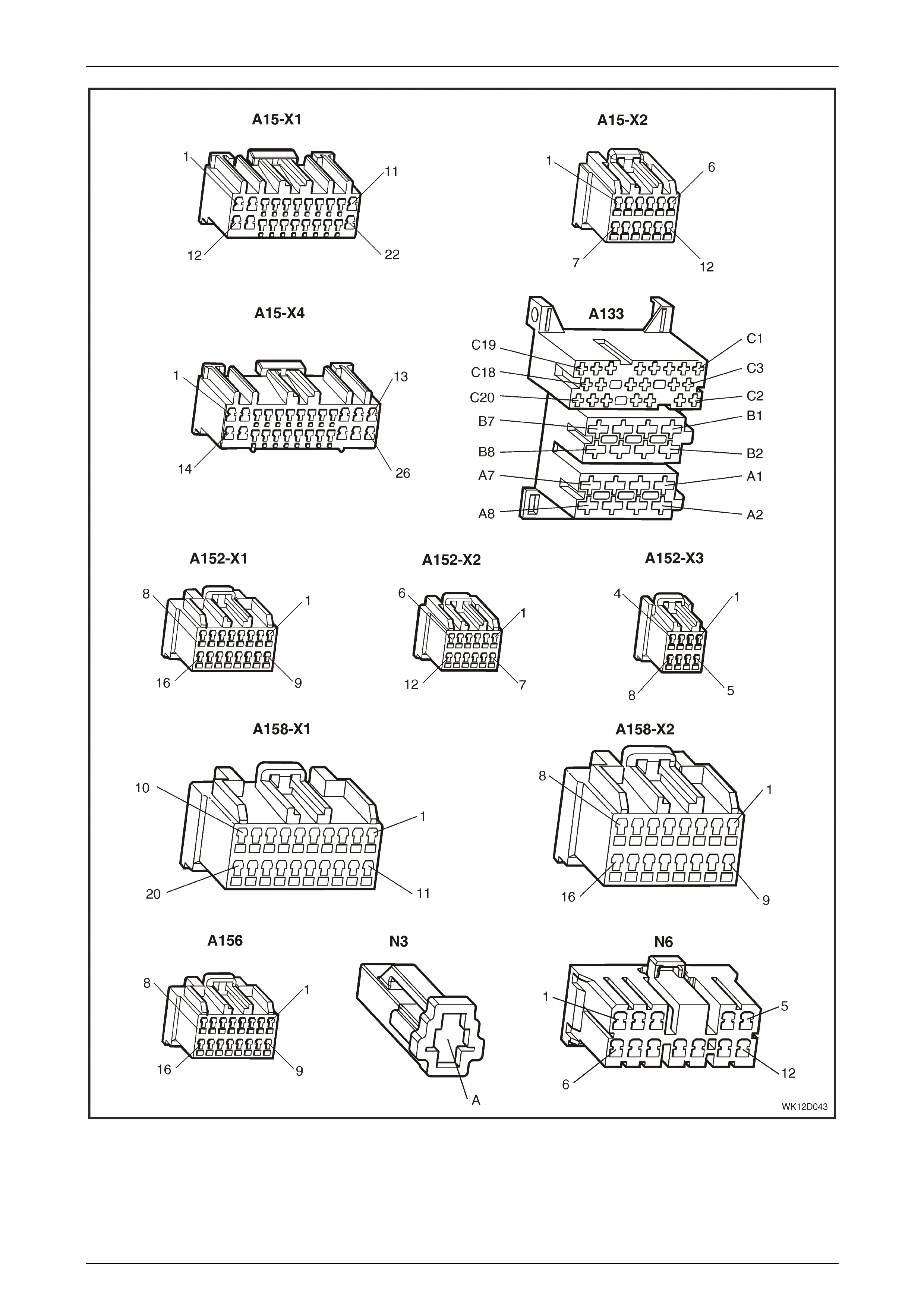
Entertainment System Page 12D–105
Page 12D–105
Figure 12D – 116
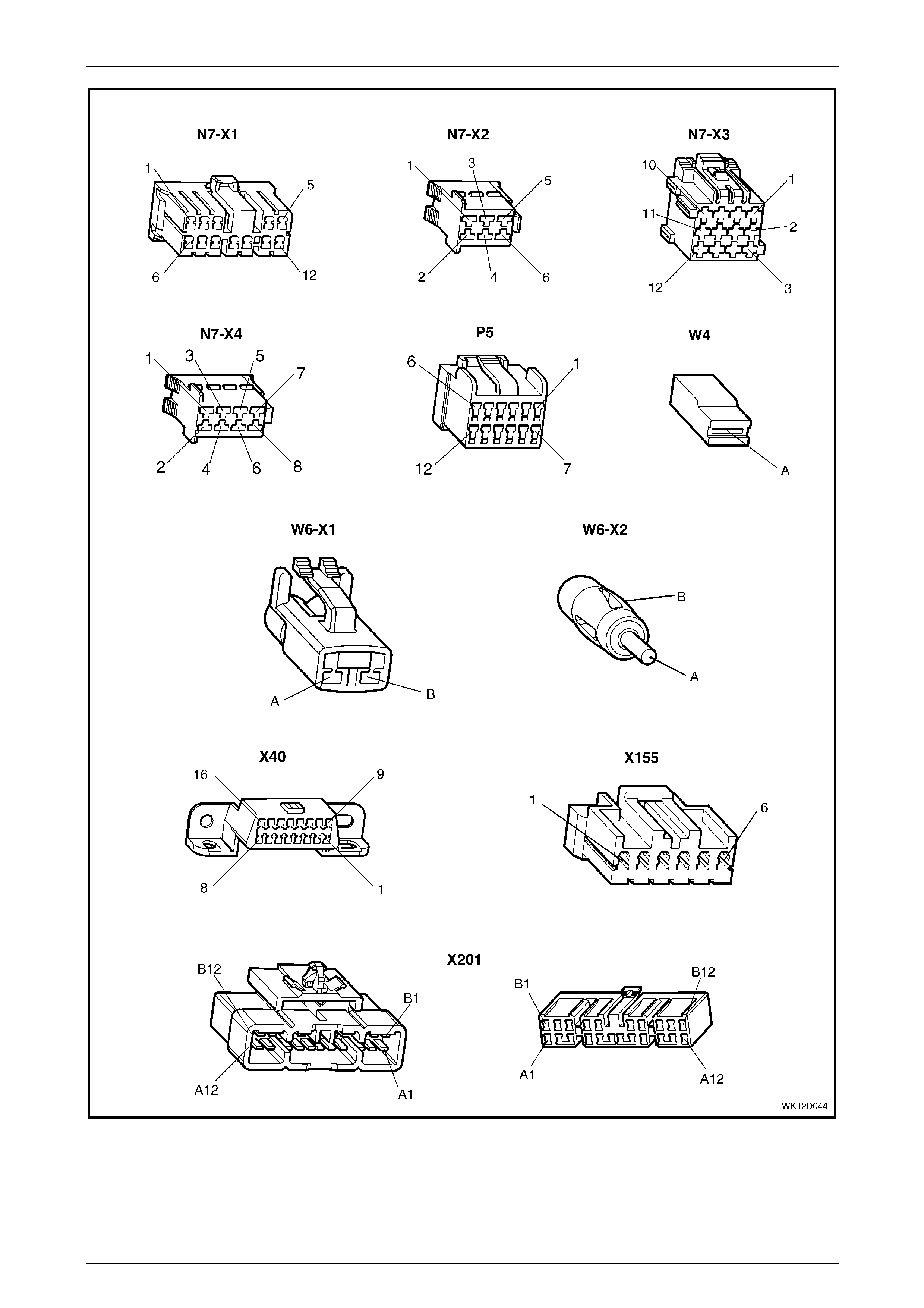
Entertainment System Page 12D–106
Page 12D–106
Figure 12D – 117

Entertainment System Page 12D–107
Page 12D–107
Figure 12D – 118
Figure 12D – 119

Entertainment System Page 12D–108
Page 12D–108
Audio System Diagnostic Circuit Check
When investigating any complaint of an audio system problem or malfunction, always begin diagnosis with the following
diagnostic circuit check. This check is a preliminary procedure that ensures that the audio system is powered up,
communicating on the serial data line, helping to identify a problem or malfunction, and directing the reader to the
appropriate diagnostic chart in this Section.
With TECH 2 connected to the DLC and the ignition switched on, TECH 2 should display serial data communication. If
TECH 2 does not display serial data, the serial data circuit may be open or shorted.
The entertainment system and several other control modules are connected to the serial data line. The control modules
are the PCM, PIM (GEN III V8 only) BCM, ABS or ABS / TCS, OCC and SRS. The entertainment system or ANY one of
the control modules could cause a fault on the serial data line. This fault could result in TECH 2 not being able to display
serial data.
A udio System Diagnostic Circuit Check Diagnostic Chart
Step Action Value(s) Yes No
1 Turn the ignition to the accessories position.
Switch the audio system on and select FM Mode.
Does the antenna raise and does the radio function
correctly?
Go to Step 2. Go to Step 3.
2 Insert a CD, label side upwards.
Does the antenna lower and does the CD function
correctly?
Verify problem with
customer. Go to Step 3.
3 At Step 1 or 2, did the audio system display illuminate? Go to Step 5. Go to Step 4.
4 Turn the ignition off.
Gain access to the instrument panel fuse and relay
panel by pulling outwards on the upper edge of the
instrument panel lower trim panel to disengage the
retaining clips .
Check the condition of the following fuses:
PARK LAMPS / INSTRUMENTS fuse F4,
HAZARD LAMPS / ANTENNA DRIVE fuse F7,
IGNITION fuse F10,
INSTRUMENT ILLUMINA TION fuse F11,
RADIO / CELLULAR PHONE / AIM fuse F16,
RADIO / CELLULAR PHONE / SATNAV fuse F23,
and
SUBWOOFER AMPLIFIER fuse F24 or
PREMIUM SOUND AMPLIFIER fuse F24.
Are the fuses OK?
Go to Step 5. Replace faulty fuse.
5 Turn the ignition off.
Connect TECH 2 to the DLC.
Turn the ignition on.
Push the power button on TECH 2.
Does TECH 2 power up? (Screen should illuminate and
display TECH 2).
Go to Step 6. Go to TECH 2
diagnosis. Refer to
Section 0C, TECH 2
in the MY 2003 VY
and V2 Series
Service Information.

Entertainment System Page 12D–109
Page 12D–109
Step Action Value(s) Yes No
6 At the TECH 2 title screen press the Enter key.
Select Diagnostics / Model Year / Vehicle Model / Body
/ Audio Sys tem.
Does TECH 2 display Audio System Identification (i.e.
Part Number)?
Confirm the details
and go to Step 7. Go to
DTC 40 No BCM
Serial Data
In this Section.
7 Select Diagnostic Trouble Codes / Read Current DTC
Information.
Does TECH 2 display any DTC?
Refer to
corresponding
Diagnostic Trouble
Code chart in this
Section.
Refer to
Diagnosing Faults
Not Covered By
Diagnostic Trouble
Codes
in this Section.
WHEN ALL DIAGNOSIS AND REPAIRS ARE COMPLETED, CLEAR ALL DTC AND VERIFY CORRECT
OPERATION
Diagnosing Faults Not Covered By Di agnostic Trouble Codes
Some of components associated with the audio system do not set a DTC in the event of a component failure. The
following diagnostic procedures are devised to assist in these cases:
• Power On / Off • Hands-free Telephone Unit
• No Sound or Distorted Sound - Level 1 to 4 Vehicles • Electric Antenna – Full Up / Down
• No Sound or Distorted Sound - Level 5 Vehicles • Electric Antenna – Height Adjustable
• Rear Seat Headphones No Sound • Single CD Player
• Rear Remote Control • CD Changer
• Audio Unit Display - Level 1 Vehicles • Radio Reception
• Multi Function Display - Level 2 to 5 Vehicles • Subwoofer Amplifier
• Audio Head Unit Illumination
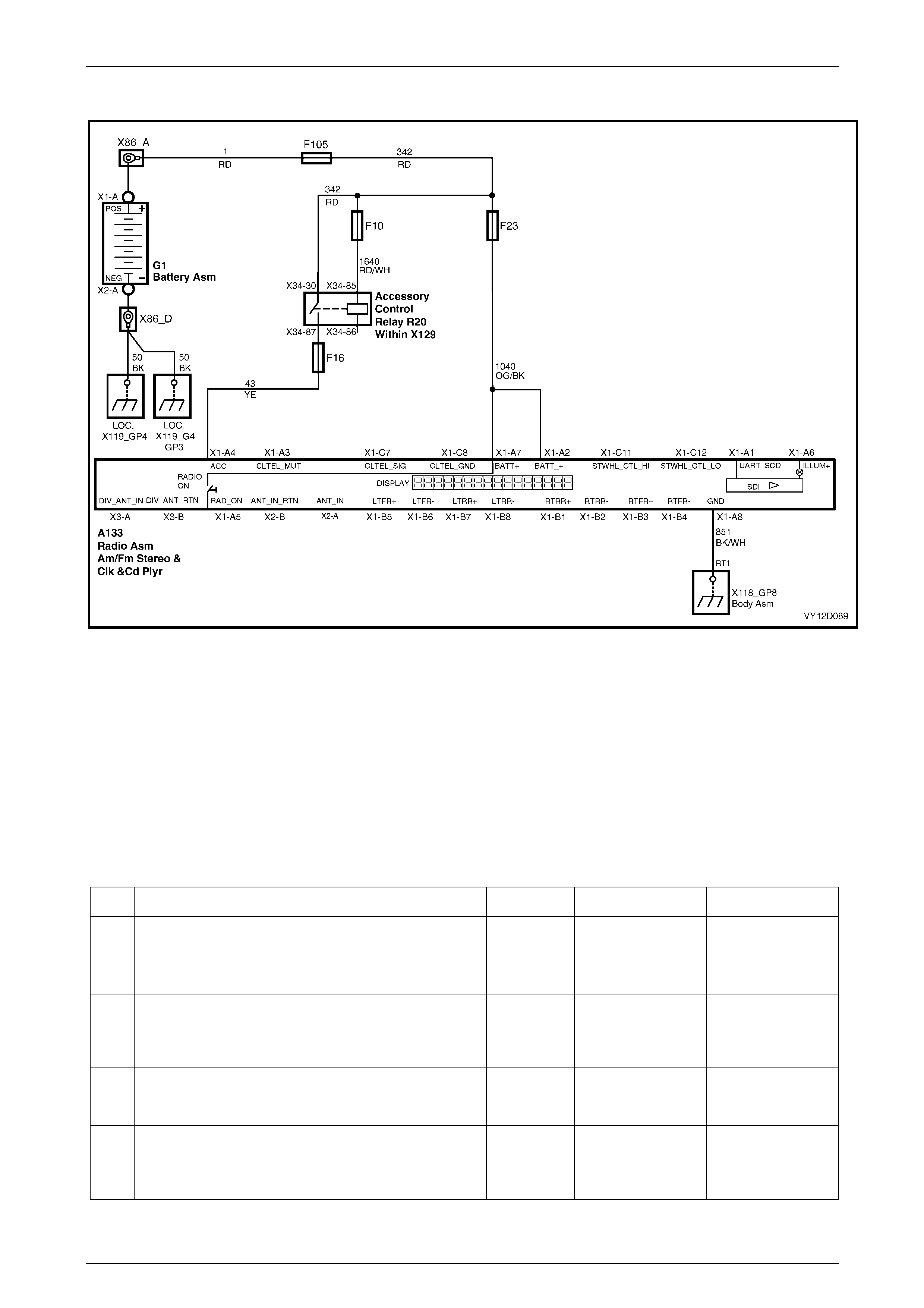
Entertainment System Page 12D–110
Page 12D–110
Power On / Off
Figure 12D – 120
The audio system uses an ISO standard radio connector with integral fuse. Terminal X1-A7 and X1-A2 are supplied with
permanent battery power via circuit 1040. Connection to vehicle ground is made on terminal X1-A8 via circuit 851. The
connector contains a blade fuse of 10 A or 15 A rating depending on the audio system fitted.
The audio head unit has many sub-circuits that can only operate properly when the battery voltage is above 9 V. When
the voltage drops below 9 V, for example during engine starting, the audio head unit will turn-off to prevent unexpected
operation.
The audio head unit can request the accessories line to turn on even after the ignition is turned off and the key removed.
To do this, press the ON button. The accessories line will operate for approximately 1 hour, then will turn off unless the
audio head unit is turned on once more.
Power On / Off Diagnostic Chart
Step Action Value(s) Yes No
1 Was the Audio System Diagnostic Circuit Check
performed? Go to Step 2. Go to Audio
System Diagnostic
Circuit Check
in this Section.
2 Ensure that the ignition switch is in the Off position.
Is the clock visible on the display and does the Security
LED flash?
Go to Step 3. Go to Step 4.
3 Switch the audio system on.
Does the radio turn on and operate correctly?
Go to Step 11. Go to Step 4.
4 Check for uneven gaps around the audio head unit and
trim.
Is unit properly located in the console?
Go to Step 6. Go to Step 5.

Entertainment System Page 12D–111
Page 12D–111
Step Action Value(s) Yes No
5 Push the audio head unit into the console using firm
pressure applied over the removal tool holes.
Is the problem rectified?
End of diagnostics.
Unit not installed
correctly.
Go to Step 6.
6 Remove the audio system head unit. Refer to
2.1 Audio System Head Unit in this Section.
Using a digital mult ime ter, measure the power supply
voltage, circui t 1040, between audio head unit
connector A133, terminal X1-A7 and a known good
ground.
Is the value as specified?
Within 0.5 V
of battery
voltage, and
above 9.0 V
Go to Step 8. Go to Step 7
7 Check the condition of the RADIO fuse F23, located on
the instrument panel fuse and relay panel. Replace if
necessary.
Check connectors for terminal retention. Repair if
necessary.
Install the audio system head unit (refer to
2.1 Audio System Head Unit in this Section) and
check operation in radio and CD modes.
Does the unit operate correctly?
End of diagnostics. Go to Step 8.
8 Remove the audio system head unit. Refer to
2.1 Audio System Head Unit in this Section.
Remove fuse F23 from the instrument panel fuse and
relay panel.
Using a digital ohmmeter, check continuity of the power
supply, circuit 1040, between fuse holder and audio
head unit connector A133, terminal X1-A7.
Is the value as specified?
Less than
1 ohm Go to Step 9. Repair faulty
circuit 1040.
9 Using a digital ohmmeter, check continuity of the
ground connection, circuit 851, between audio head unit
connector A133, terminal X1-A8 and a known good
ground.
Is the value as specified?
Less than
1 ohm Go to Step 10. Repair faulty circuit
851.
10 Using a digital ohmmeter, check the continuity of the
fuse located on the connec tor at the rear of the audio
head unit.
Is the value as specified?
Less than
1 ohm Replace the audio
system head unit.
Refer to
2.1 Audio System
Head Unit
in this Section.
Replace fuse.
11 Turn the ignition to the Accessories position.
Switch the audio system on.
Turn the ignition off and open the driver’s door.
Does the audio system also turn off?
Confirm fault with
customer. Go to Step 12.
12 Check the condition of the IGNITION fuse F10 and the
RADIO / CELLULAR PHONE fuse F16 on the
instrument panel fuse and relay panel.
Are the fuses OK?
Go to Step 13. Replace fuses as
appropriate.

Entertainment System Page 12D–112
Page 12D–112
Step Action Value(s) Yes No
13 Remove the audio system head unit. Refer to
2.1 Audio System Head Unit in this Section.
Connect a digital voltmeter between the Accessories
voltage input, circuit 43, at audio head unit connector
A133, terminal X1-A4 and a known good ground.
Check the Accessories voltage while turning the ignition
between the Off position and the Accessories position.
Does the voltage appear at the Accessories position?
Battery
voltage Replace the audio
system head unit.
Refer to
2.1 Audio System
Head Unit
in this Section.
Repair faulty
circuit 43.
WHEN ALL DIAGNOSIS AND REPAIRS ARE COMPLETED, VERIFY CORRECT OPERATION
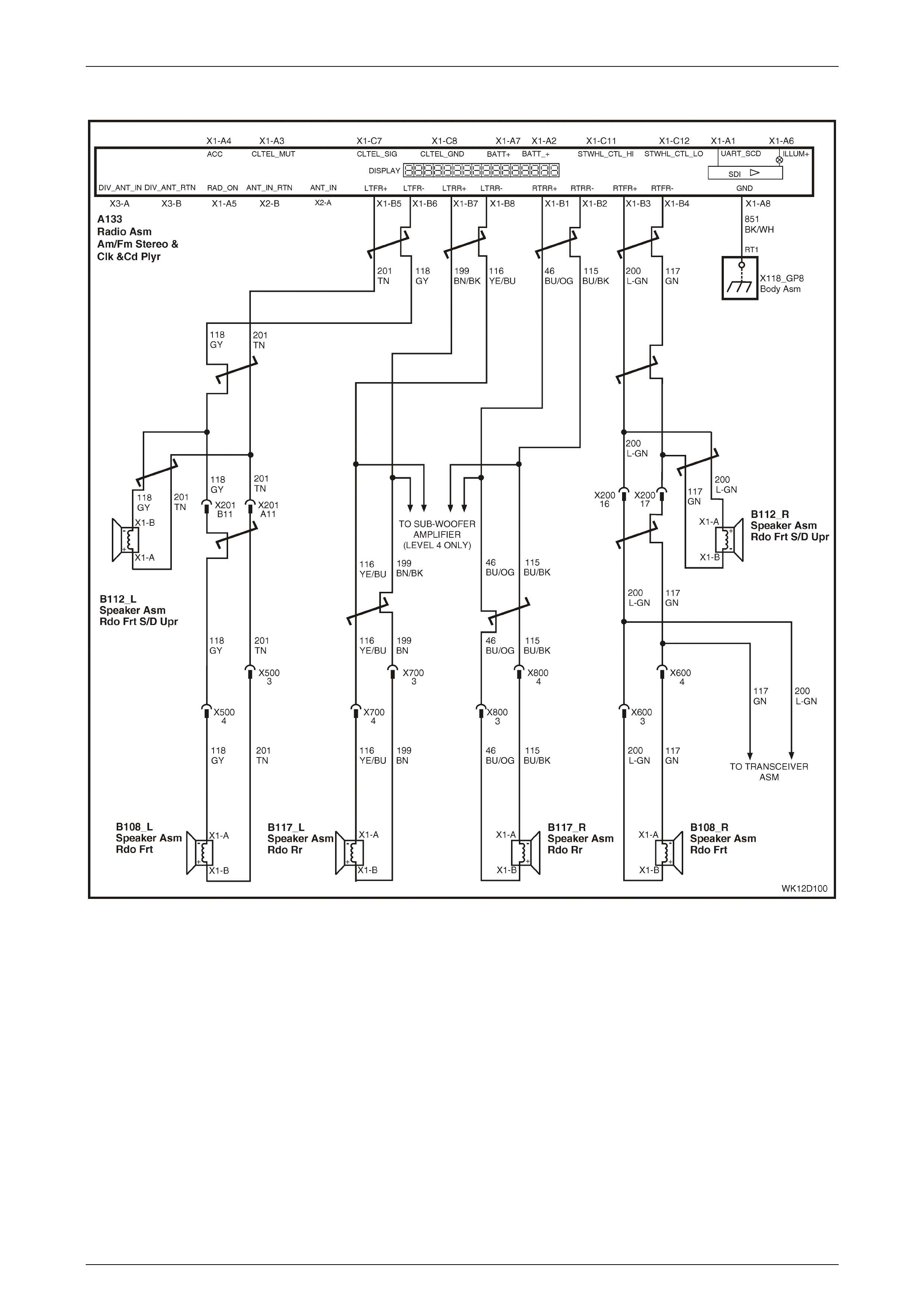
Entertainment System Page 12D–113
Page 12D–113
No Sound Or Distorted Sound – Level 1 t o 4 Vehicles
Figure 12D – 121
The Audio Systems fitted to the MY 2004 WK series Level 1 to 4 vehicles have modern amplifiers that deliver high power
and are internally protected against short circuits and connection to voltage sources.
Level 2 to 4 vehicles feature a high power 4 x 30 W RMS amplifier that drives 2 ohm speakers in the doors and tweeters
in the instrument panel. Level 4 vehicles also have two subwoofers driven by a separate 2 x 40 W RMS amplifier fitted to
the parcel shelf to increase the frequency response of the system. Level 1 models have 4 x 20 W RMS amplifiers.
Speakers in these vehicles are 4 ohms for the doors and 2 ohms for the tweeters.
All Audio Systems have a Distortion Limiting circuit. This circuit, when turned on, automatically limits the volume level to
the point where distortion begins. The amount of distortion will depend on the amount of bass in the music. Listeners who
find that the music does not play loud enough with the distortion limiting circuit activated can either:
• reduce the amount of bass, or
• turn the distortion limiting off using the instrument cluster MFD (refer to Section 12C, 1.8 Customisation Mode –
Audio Distortion Limiting in the MY 2003 VY and V2 Series Service Information).

Entertainment System Page 12D–114
Page 12D–114
Damaged speakers and wiring may not cause a failure when played at low volume levels. At low volume the amplifier
may cope with the additional load caused by the damage. Problems may only become obvious when playing at loud
volume levels. Typical symptoms will be
• one speaker dropping out,
• two speakers dropp ing out, or
• all speakers dropping out.
When the amplifier has cooled, the output may resume from the affected speaker or speakers.
No Sound Or Distorted Sound Diagnostic Chart
Step Action Value(s) Yes No
1 Was the Audio System Diagnostic Circuit Check
performed? Go to Step 2. Go to Audio System
Diagnostic Circuit
Check in this
Section.
2 Turn the ignition to the accessories position.
Switch the audio system on and set the volume at
medium level.
Play a CD.
Does the audio system turn on and seem normal apart
from no sound or distorted sound?
Go to Step 3. Go to Power On /
Off Diagnostic Chart
in this Section.
3 Set EQ to OFF, and Bass, Treble, Fader and Balance to
STD.
Use the Fader and Balance settings to check that each
speaker is operating, including the instrument panel
tweeters and rear parcel shelf subwoofers (if fitted).
Is no sound or distortion from one speaker only?
Go to Step 4. Go to Step 10.
4 Set Fader and Balance to STD.
Remove the audio system head unit. Refer to
2.1 Audio System Head Unit in this Section.
Using a digital ohmmeter, check the resistance of the
defective speaker circuit at audio head unit connector
A133:
• Left Front – X1-B5 and X1-B6
• Left Rear – X1-B7 and X1-B8
• Right Front – X1-B3 and X1-B4
• Right Rear – X1-B1 and X1-B2
Is the value as specified?
Between
2 ohms and
4 ohms
Go to Step 5. Go to Step 10.
5 Remove the defective speaker. Refer to
2 Service Operations in this Section.
Inspect the speaker for damage or foreign material.
Do the speaker terminals appear damaged?
Remove foreign
material. Replace
speaker if damaged.
Refer to
2 Service
Operations
in this Section.
Go to Step 6.
6 Has the speaker or speaker terminals been making
contact with body metal components? Rectify reason for
contact. Install
speaker.
Go to Step 7.

Entertainment System Page 12D–115
Page 12D–115
Step Action Value(s) Yes No
7 Using a digital ohmmeter, check the resistance across
the speaker terminals.
Is the value as specified?
Between
2 ohms and
4 ohms
Go to Step 8. Replace speaker.
Refer to
2 Service
Operations
in this Section.
8 Using a digital ohmmeter, check for continuity between
each of the speaker circuits at audio head unit
connector A133, and a known good ground:
• Left Front – X1-B5, circuit 201
• Left Front – X1-B6, circuit 118
• Left Rear – X1-B7, circuit 199
• Left Rear – X1-B8, circuit 116
• Right Front – X1-B3, circuit 200
• Right Front – X1-B4, circuit 117
• Right Rear – X1-B1, circuit 46
• Right Rear – X1-B2, circuit 115
Is any circuit shorted to ground?
Repair defective
circuit. Go to Step 9.
9 Using a digital voltmeter, check for voltage between
each of the speaker circuits at audio head unit
connector A133, and a known good ground:
• Left Front – X1-B5, circuit 201
• Left Front – X1-B6, circuit 118
• Left Rear – X1-B7, circuit 199
• Left Rear – X1-B8, circuit 116
• Right Front – X1-B3, circuit 200
• Right Front – X1-B4, circuit 117
• Right Rear – X1-B1, circuit 46
• Right Rear – X1-B2, circuit 115
Is voltage indicated at any circuit?
0 volts Repair defective
circuit. Go to Step 10.
10 Using a digital ohmmeter, measure the resistance
between audio head unit connector A133, terminal X1-
A8, circuit 851 and body ground.
Is the value as specified?
Less than
1 ohm Go to Step 11. Repair defective
circuit 851.
11 Install the audio system head unit (refer to
2.1 Audio System Head Unit in this Section), and
any speakers.
Turn the ignition to the Accessories position.
Switch the audio system on and play a CD.
Increase the volume to a loud level.
Allow the audio system to play for 5 minutes.
Has the problem appeared?
Go to Step 12. Confirm fault with
customer.

Entertainment System Page 12D–116
Page 12D–116
Step Action Value(s) Yes No
12 Allow the audio system to cool.
Using the Fader and balance settings, repeat Step 11
for the front and rear / left and right speakers.
Has the test found one speaker to be the cause?
Go to Step 13. Replace the audio
system head unit.
Refer to
2.1 Audio System
Head Unit
in this Section
13 Replace the defective speaker. Refer to
2. Service Operations in this Section.
Is the problem rectified?
End of diagnostics. Replace the audio
system head unit.
Refer to
2.1 Audio System
Head Unit
in this Section
WHEN ALL DIAGNOSIS AND REPAIRS ARE COMPLETED, VERIFY CORRECT OPERATION
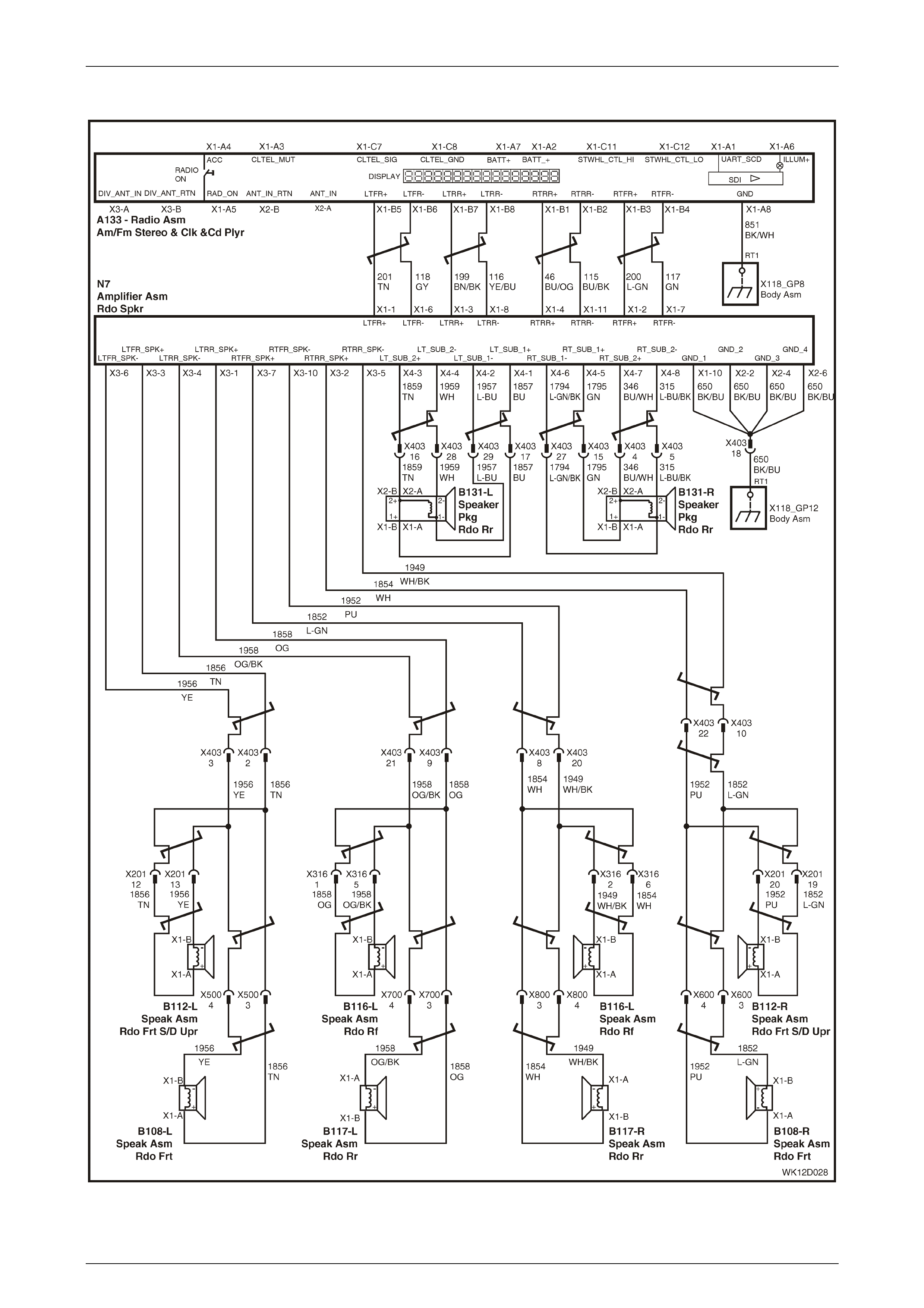
Entertainment System Page 12D–117
Page 12D–117
No Sound Or Distorted Sound – Level 5 Vehicles
Figure 12D – 122

Entertainment System Page 12D–118
Page 12D–118
The Audio System fitted to the MY 2004 WK Series Level 5 vehicles has a Premium Sound amplifier mounted in the rear
of the car that delivers high power to all of the upgraded vehicle speakers. The four channel sound output from the audio
head unit is taken to the amplifier where it passes through a DSP system before being amplified and sent to the vehicle
speakers. The amplifier is internally protected against short circuits and connection to voltage sources on the speaker
wires.
The Level 5 audio system has a Distortion Limiting circuit. This circuit, when turned on, automatically limits the volume
level to the point where distortion begins. The amount of distortion will depend on the amount of bass in the music.
Listeners who find that the music does not play loud enough with the distortion limiting circuit activated can either:
• reduce the amount of bass, or
• turn the distortion limiting off using the instrument cluster MFD (refer to Section 12C, 1.8 Customisation Mode –
Audio Distortion Limiting in the MY 2003 VY and V2 Series Service Information).
Damaged speakers and wiring may not cause a failure when played at low volume levels. At low volume the amplifier
may cope with the additional load caused by the damage. Problems may only become obvious when playing at loud
volume levels. Typical symptoms will be
• one speaker dropping out or sounding dist orte d,
• two speakers dropp ing out, or
• all speakers dropping out.
When the amplifier has cooled, the output may resume from the affected speaker or speakers.
The Premium Amplifier is connected to main vehicle communications bus, and therefore has its own TECH 2 diagnostic
capability. The high power requirements of the Premium Amplifier mean the power supply and earth circuits are very
important to ensure smooth operation. Carefully inspect each connection to make sure they are tight and free from
corrosion.
No Sound Or Distorted Sound Diagnostic Chart
Step Action Value(s) Yes No
1 Was the Audio System Diagnostic Circuit Check
performed? Go to Step 2. Go to Audio System
Diagnostic Circuit
Check in this
Section.
2 Turn the ignition to the Accessories position.
Switch the audio system on and set the volume at
medium level.
Play a CD.
Does the audio system turn on and seem normal apart
from no sound or distorted sound?
Go to Step 3. Go to Power On /
Off Diagnostic Chart
in this Section.
3 Set EQ to OFF, and Bass, Treble, Fader and Balance to
STD.
Use the Fader and Balance settings to check that each
speaker is operating, including the instrument panel
tweeters and rear parcel she lf subwoofers.
Is no sound or distortion from one speaker only ?
Go to Step 4. Refer to
3.18 Premium
Sound Amplifier
Diagnostic
Procedures in this
Section for further
diagnosis.
4 Remove the defective speaker. Refer to
2 Service Operations in this Section.
Inspect the speaker for damage or foreign material.
Do the speaker terminals appear damaged?
Remove foreign
material. Replace
speaker if damaged.
Refer to
2 Service
Operations
in this Section.
Go to Step 5.

Entertainment System Page 12D–119
Page 12D–119
Step Action Value(s) Yes No
5 Using a digital ohmmeter, check the resistance of the
defective speaker across the speaker terminals:
NOTE
The Premium Sound subwoofer has two
sets of connectors on each speaker. Each
connector has the start and finish of a
separate spe aker cir cu it.
Is the value as specified?
Approximately
2 ohms Go to Step 6 Replace speaker.
Refer to
2 Service
Operations
in this Section.
6 Has the speaker or speaker terminals been making
contact with body metal components? Rectify reason for
contact. Install
speaker.
Go to Step 7.
7 Disconnect the Premium Sound amplifier connectors N7
X3 and N7 X4. Refer to Figure 12 D – 41 in this Section
for connector identification details.
Using a digital ohmmeter, check for continuity between
each of the speaker circuits at Premium Sound amplifier
connectors N7 X3 and N7 X4, and a known good
ground:
• Left Front – X3-6, circuit 1956
• Left Front – X3-3, circuit 1856
• Left Rear – X3-4, circuit 1958
• Left Rear – X3-1, circuit 1858
• Right Front – X3-7, circuit 1852
• Right Front – X3-10, circuit 1952
• Right Rear – X3-2, circuit 1854
• Right Rear – X3-5, circuit 1949
• Left subwoofer B – X4-3, circuit 1859
• Left subwoofer B – X4-1, circuit 1857
• Left subwoofer A – X4-4, circuit 1959
• Left subwoofer A – X4-2, circuit 1957
• Right subwoofer A – X4-6, circuit 1794
• Right subwoofer A – X4 –8, circuit 315
• Right subwoofer B – X4 – 5, circuit 1795
• Right subwoofer B – X4 – 7, circuit 346
Is any circuit shorted to ground?
Isolate short circuit
and repair the
defective circuit.
Go to Step 8.

Entertainment System Page 12D–120
Page 12D–120
Step Action Value(s) Yes No
8 Using a digital voltmeter, check for voltage between
each of the speaker circuits at Premium Sound amplifier
connectors N7 X3 and N7 X4, and a known good
ground:
• Left Front – X3-6, circuit 1956
• Left Front – X3-3, circuit 1856
• Left Rear – X3-4, circuit 1958
• Left Rear – X3-1, circuit 1858
• Right Front – X3-7, circuit 1852
• Right Front – X3-10, circuit 1952
• Right Rear – X3-2, circuit 1854
• Right Rear – X3-5, circuit 1949
• Left subwoofer B – X4-3, circuit 1859
• Left subwoofer B – X4-1, circuit 1857
• Left subwoofer A – X4-4, circuit 1959
• Left subwoofer A – X4-2, circuit 1957
• Right subwoofer A – X4-6, circuit 1794
• Right subwoofer A – X4 –8, circuit 315
• Right subwoofer B – X4 – 5, circuit 1795
• Right subwoofer B – X4 – 7, circuit 346
Is voltage indicated at any circuit?
0 volts Repair defective
circuit. Go to Step 9.
9 Remove the audio system head unit. Refer to
2.1 Audio System Head Unit in this Section.
Using a digital ohmmeter, check for continuity between
each of the speaker circuits at audio head unit
connector A133 X1, and a known good ground:·
• Left Front – X1-B5, circuit 201
• Left Front – X1-B6, circuit 118
• Left Rear – X1-B7, circuit 199
• Left Rear – X1-B8, circuit 116
• Right Front – X1-B3, circuit 200
• Right Front – X1-B4, circuit 117
• Right Rear – X1-B1, circuit 46
• Right Rear – X1-B2, circuit 115
Is any circuit shorted to ground?
Repair defective
circuit. Go to Step 10.

Entertainment System Page 12D–121
Page 12D–121
Step Action Value(s) Yes No
10 Using a digital voltmeter, check for voltage between
each of the speaker circuits at audio head unit
connector A133 X1, and a known good ground:
• Left Front – X1-B5, circuit 201
• Left Front – X1-B6, circuit 118
• Left Rear – X1-B7, circuit 199
• Left Rear – X1-B8, circuit 116
• Right Front – X1-B3, circuit 200
• Right Front – X1-B4, circuit 117
• Right Rear – X1-B1, circuit 46
• Right Rear – X1-B2, circuit 115
Is voltage indicated at any circuit?
0 volts Repair defective
circuit. Go to Step 11.
11 Using a digital ohmmeter, measure the resistance
between audio head unit connector A133, terminal
X1-A8, circuit 851 and body ground.
Is the value as specified?
Less than 1
ohm Go to Step 12. Repair defective
circuit 851.
12 Disconnect the Premium Amplifier connectors N7-X1
and N7-X2.
Using a digital ohmmeter, measure the resistance
between amplifier connector N7-X2, terminal X2-2, X2-4
and X2-6, circuit 650 and body ground. Also, measure
the resistance between amplifier connector N7-X1,
Terminal X1-10, circuit 650 and body ground.
Is the value as specified?
Less than 1
ohm Go to Step 13. Repair defective
circuit 650.
13 Install the audio system head unit (refer to
2.1 Audio System Head Unit in this Section), and any
speakers.
Turn the ignition to the Accessories position.
Switch the audio system on and play a CD.
Increase the volume to a loud level.
Allow the audio system to play for 5 minutes.
Has the problem appeared?
Go to Step 14. Confirm fault with
customer.
14 Using the Fader and balance settings, repeat Step 13
for the front and rear / left and right speakers.
Has the test found one speaker to be the cause?
Go to Step 15. Replace the audio
system head unit.
Refer to
2.1 Audio System
Head Unit
in this Section.
15 Replace the defective speaker. Refer to
2 Service Operations in this Section.
Is the problem rectified?
End of diagnostics. Replace the audio
system head unit.
Refer to
2.1 Audio System
Head Unit
in this Section
WHEN ALL DIAGNOSIS AND REPAIRS ARE COMPLETED, VERIFY CORRECT OPERATION
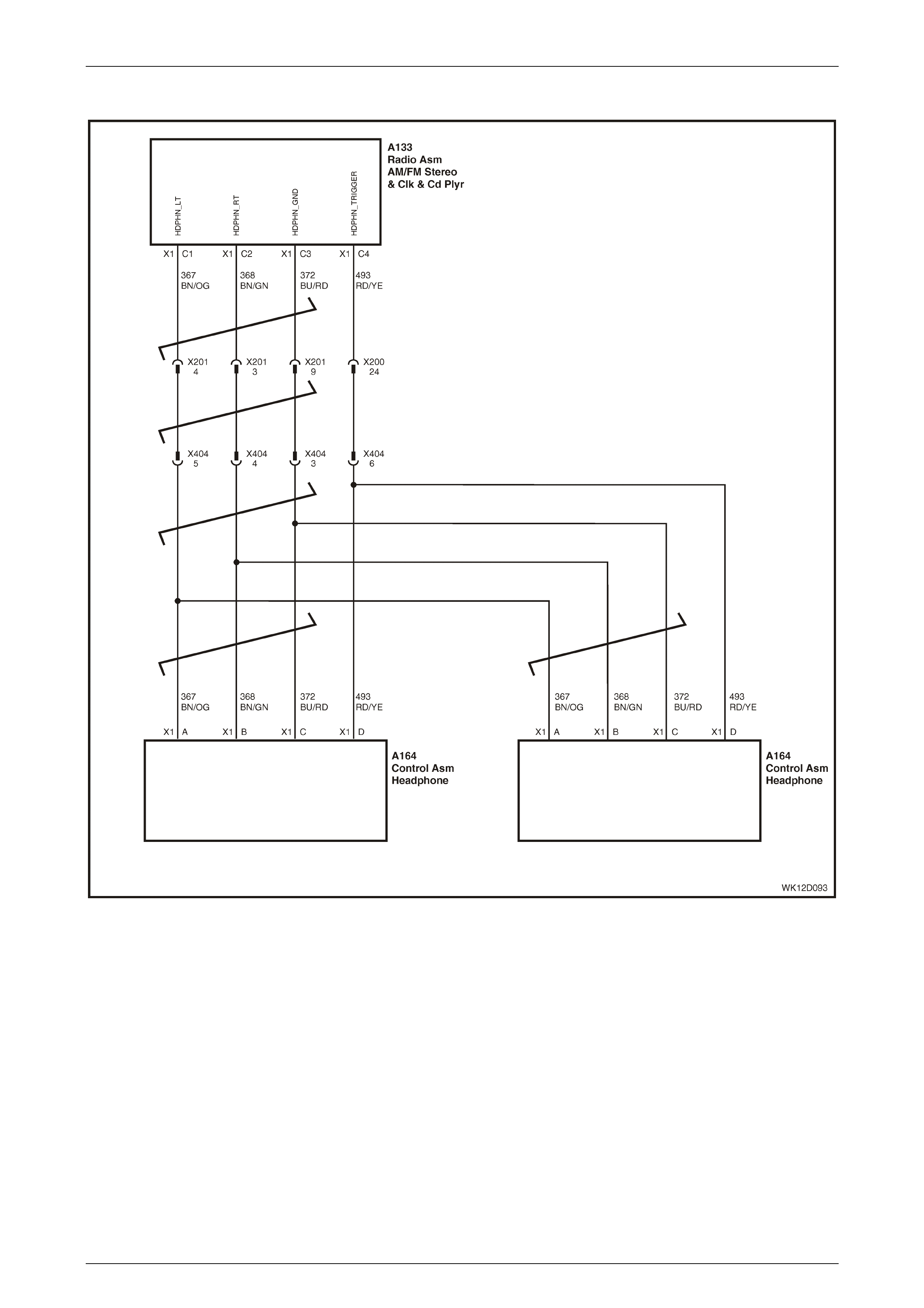
Entertainment System Page 12D–122
Page 12D–122
Rear Seat Headphones No Sound
Figure 12D – 123
Level 5 vehicles are fitted with rear seat headphone jacks located under a hinged cover in the centre of the rear window
trim panel assembly. The headphones allow the rear passengers to simultaneously listen to a different sound source
than the front seat occupants.

Entertainment System Page 12D–123
Page 12D–123
Rear Seat Headphones No Sound Diagnostic Table
Step Action Value(s) Yes No
1 Was the Audio System Diagnostic Circuit Check
performed? Go to Step 2. Go to
Audio System
Diagnostic Circuit
Check
in this Section.
2 Switch on the ignition and audio head unit, select a
radio station or CD and adjust the volume to a
comforta ble lev el.
If applicable, remove the headphone jacks from their
sockets.
Confirm other parts of the audio system work as
expected, eg select other radio stations, play different
CDs etc.
Does the audio system operate as expected?
Go to Step 3. Rectify other audio
related problems
first.
3 Ensure that the headphones are not disabled at the
audio head unit. Refer to 1.1 G eneral De scr iption –
Rear Seat Headphone in this Section.
Using known good headphones, insert the 6.5mm
headphone jack into one of the sockets, and then the
other socket.
Does the audio system display a ‘headphones
connected’ message from at least one of the sockets?
Go to Step 4. Go to Step 5.
4 Did both sockets give the ‘headphones connected’
message? Go to Step 7. Replace headphone
jack assembly.
Refer to
2.13 Rear
Headphone Ja ck s
in this Section.
5 Remove the audio system head unit. Refer to
2.1 Audio System Head Unit in this Section.
Using a digital ohmmeter, measure the resistance at
audio head unit connector A133 between terminal
X1-C3, circuit 372 and terminal X1-C4, circuit 493.
Is the resistance as specified?
Jack inserted
= 0 ohms.
Jack
removed =
open circuit .
Replace audio head
unit. Refer to
2.1 Audio System
Head Unit
in this Section.
Go to Step 6.
6 Using a digital ohmmeter, measure the resistance at
headphone connector X404 between terminal X404-3,
circuit 372 and terminal X404-6, circuit 493.
Is the resistance as specified?
Jack inserted
= 0 ohms.
Jack
removed =
open circuit .
Repair faulty
circuit 372 or
circuit 473 in body
wiring.
Replace headphone
jack assembly.
Refer to
2.13 Rear
Headphone Ja ck s
in this Section.
7 Connect the headphones to each of the sockets, one
socket at a time.
Does any audio play through either one of the
headphone sockets?
Go to Step 8. Go to Step 9.
8 Did both sockets give equal audio output level and left
to right speaker balance? i.e. do both sockets give the
same sounding audio? Note the results carefully.
Go to Step 9. Replace headphone
jack assembly.
Refer to
2.13 Rear
Headphone Ja ck s
in this Section.

Entertainment System Page 12D–124
Page 12D–124
Step Action Value(s) Yes No
9 Switch off the ignition and audio system.
Working the headphone module side, de-house and
swap terminals X404-4 and X404-5.
Reconnect connection X404.
Switch on the ignition and audio head unit, select a
radio station or CD and adjust the volume to a
comforta ble lev el.
Connect the headphones to each of the sockets, one
socket at a time.
Has the previous problem stayed as it was in step 8, or
has it changed?
Replace headphone
jack assembly.
Refer to
2.13 Rear
Headphone Ja ck s
in this Section.
Go to Step 10.
10 De-house and swap terminals X404-4 and X404-5.
Return them to their normal positions.
Remove the audio system head unit. Refer to
2.1 Audio System Head Unit in this Section.
Using a digital ohmmeter, check for continuity of circuits
367, 368 and 372 between connector X404 and the
audio head unit connector A133.
Are all resistance as specified
Short circuit? Replace the audio
system head unit.
Refer to
2.1 Audio System
Head Unit
in this Section.
Repair faulty
circuits.
WHEN ALL DIAGNOSIS AND REPAIRS ARE COMPLETED, VERIFY CORRECT OPERATION
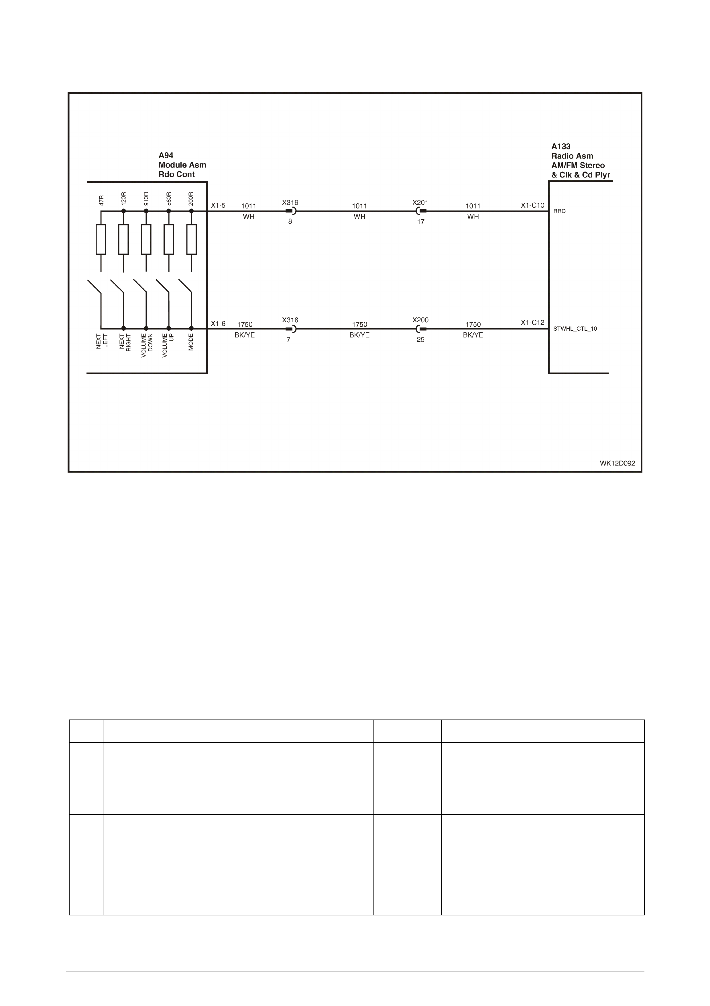
Entertainment System Page 12D–125
Page 12D–125
Rear Remote Control
Figure 12D – 124
Level 5 vehicles are fitted with a rear remote control. Control buttons located on the rear remote control provide remote
operation of various System 6 audio system functions. Like the steering wheel remote controls, the rear remote controls
are a resistive network. When a button is pressed, the change in resistance is interpreted by the audio head unit as a
button press, and the appropriate function is actioned.
NOTE
The audio head unit contains a lock-out function
for the rear remote controls to prevent rear seat
passengers from adjusting the audio system.
Refer to 1.5 Rear Remote Control in this Section
for a detailed description of the lock-out function.
Rear Remote Control Diagnostic Chart
Step Action Value(s) Yes No
1 Was the Audio System Diagnostic Circuit Check
performed? Go to Step 2. Go to
Audio System
Diagnostic Circuit
Check
in this Section.
2 Switch the ignition and audio head unit on.
Ensure that rear roof controls are unlocked.
Press each of the rear seat remote control buttons and
note if the audio head unit follows the command.
Does the audio system operate as expected?
Confirm fault with
customer. Go to Step 3.

Entertainment System Page 12D–126
Page 12D–126
Step Action Value(s) Yes No
3 Connect TECH 2 to the DLC.
Select Diagnostics / Model Year / Vehicle Model / Body
/ Audio System / Data Display / Data List.
Scroll to Rear Remote Control in the TECH 2 menu.
Do not press any button on the rear remote controls.
Does TECH 2 display KEY RELEASED?
Go to Step 4. Go to Step 5.
4 Press each of the rear remote control buttons in turn.
Does TECH 2 correctly display the name of each button
when pressed, but the AHU does not process the button
as shown?
Replace the audio
system head unit.
Refer to
2.1 Audio System
Head Unit
in this Section.
Go to Step 6.
5 Remove the audio system head unit. Refer to
2.1 Audio System Head Unit in this Section.
Using a digital ohmmeter, measure the resistance at
audio head unit connector A133 between terminal X1-
C10, circuit 1011 and termina l X 1-C 12, circuit 1750.
Do NOT press any button on the rear remote control.
Is the resistance as specified?
Open circuit Go to Step 6. Go to Step 7.
6 With the ohmmeter connected as in Step 5, press each
button on the rear remote control one at a time and
record the resistances for each button press.
Do the resistances match those specified?
MODE = 190
to 210 ohms
VOL UP =
532 to
588 ohms
VOL DWN =
865 to
955 ohms
NEXT < = 45
to 49 ohms
NEXT > =
114 to
126 ohms
Go to Step 8. Go to Step 7.
7 Remove the rear remote control module and unplug
connector A94. Refer to 2.12 Rear Remote Control in
this Section.
Using a digital ohmmeter, re-measure the resistances at
the remote control module connector A94, terminals
X1-5 and X1-6.
Press each button in turn and record the resistances.
Are the resistances as specified?
MODE = 190
to 210 ohms
VOL UP =
532 to
588 ohms
VOL DWN =
865 to
955 ohms
NEXT < = 45
to 49 ohms
NEXT > =
114 to
126 ohms
Diagnose and repai r
circuit 1011 and
circuit 1750.
Replace the rear
remote control
module. Refer to
2.12 Rear Remote
Control
in this Section.
8 Using a digital ohmmeter, measure the resistance at
audio head unit connector A133 between terminal X1-
C12, circuit 1750 and a known good ground.
Is the resistance as specified
Less than 2
ohms. Replace the audio
system head unit.
Refer to
2.1 Audio System
Head Unit
in this Section.
Repair circuit 1750.
WHEN ALL DIAGNOSIS AND REPAIRS ARE COMPLETED, VERIFY CORRECT OPERATION

Entertainment System Page 12D–127
Page 12D–127
Audio Unit Display – Level 1 Vehi cles
The audio system head unit fitted to Level 1 vehicles has a large dot-matrix display on the fascia. The display is fully
illuminated when the ignition is in the Accessories position or the audio head unit is on. When the park lamps are on, the
brightness can be adjusted using the illumination control slider on the headlamp switch.
Audio Unit Display Diagnostic Chart
Step Action Value(s) Yes No
1 Was the Audio System Diagnostic Circuit Check
performed? Go to Step 2. Go to Audio System
Diagnostic Circuit
Check in this
Section.
2 Turn the audio system on and select an FM station.
Is the display easily readable with good contrast
between the displayed characters and the background?
NOTE
During periods of low temperature, the
display characters may take longer to
change when changes are made to the
audio system selection.
Go to Step 3. Replace the audio
system head unit.
Refer to
2.1 Audio System
Head Unit
in this Section.
3 Connect TECH 2 to the DLC.
Select Diagnostics / Model Year / Vehicle Model / Body
/ Audio System / Miscellaneous Tests / Display.
Press the On soft key on the TECH 2.
Do all segments on the display illuminate?
Go to Step 4. Replace the audio
system head unit.
Refer to
2.1 Audio System
Head Unit
in this Section.
4 Press the Off soft key on the TECH 2.
Do all segments on the display extinguish?
Confirm fault with
customer. Replace the audio
system head unit.
Refer to
2.1 Audio System
Head Unit
in this Section.
WHEN ALL DIAGNOSIS AND REPAIRS ARE COMPLETED, VERIFY CORRECT OPERATION
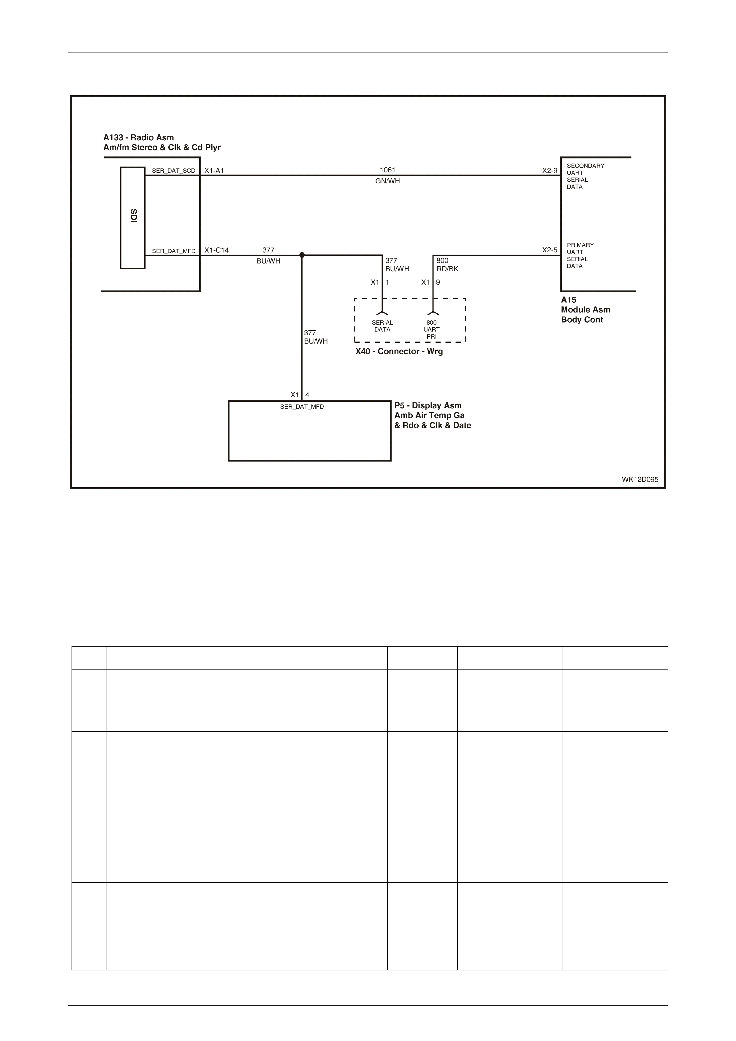
Entertainment System Page 12D–128
Page 12D–128
Multi Functi on Di splay – Level 2 to 5 Vehicles
Figure 12D – 125
The MY 2004 WK Series Level 2 to 5 audio system head units do not have an integrated display. All audio information is
sent to the MFD via a new serial communications bus. The new serial bus, called UART2 bus, is dedicated to carrying
audio display information. The UART2 protocol is similar to the standard serial communications bus and can be
diagnosed using the TECH 2.
For information on display diagnosis and display operation refer to Section 12I Multi Function Display in this Service
Information.
Multi Function Display Diagnostic Table
Step Action Value(s) Yes No
1 Was the Audio System Diagnostic Circuit Check
performed? Go to Step 2. Go to Audio System
Diagnostic Circuit
Check in this
Section.
2 Turn the ignition to the Accessories position.
Turn the audio system on and select an FM station.
Does the audio system play sound through the
speakers as expected?
Go to Step 3. Refer to
No Sound Or
Distorted Sound –
Level 1 to 4
Vehicles
or
No Sound Or
Distorted Sound –
Level 5 Vehicles
in this Section for
further diagnosis .
3 Does the MFD turn on and display climate control
information as expected? Go to Step 4. Refer to
Section 12I,
3.1 MFD
Diagnostics
in this Service
Information.

Entertainment System Page 12D–129
Page 12D–129
Step Action Value(s) Yes No
4 Connect TECH 2 to the DLC.
Select Diagnostics / Model Year / Vehicle Model / Body
/ Multi Function Display / Diagnostic Trouble Codes /
Read DTC Information
Is DTC No Serial Data from Audio System set?
Refer to
Section 12I,
3.1 MFD
Diagnostics
for further diagnosis.
Go to Step 5.
5 Select Diagnostics / Model Year / Vehicle Model / Body
/ Audio System / Diagnostic Trouble Codes / Read
Current DTC Information.
Is DTC 41 set?
Go to Step 6. Refer to
Section 12I,
3.1 MFD
Diagnostics
for further diagnosis.
6 Turn the ignition off.
Remove the audio system head unit. Refer to
2.1 Audio System Head Unit in this Section.
Turn the ignition on.
Using a digital voltmeter measure the voltage between
a known good ground and audio head unit connector
A133, terminal X1-C14.
Is the voltage as specified?
Approx.5V Replace the audio
system head unit.
Refer to
2.1 Audio System
Head Unit
in this section.
Go to Step 7.
7 Using a digital ohmmeter, measure the resistance
between a known good ground and radio connector
A133, terminal X1-C14.
Is the value as specified?
Open circuit,
no continuity. Refer to
Section 12I,
3.1 MFD
Diagnostics
for further diagnosis.
Repair short to
ground in
circuit 377.
WHEN ALL DIAGNOSIS AND REPAIRS ARE COMPLETED, VERIFY CORRECT OPERATION

Entertainment System Page 12D–130
Page 12D–130
Audio Head Unit Illumination
Figure 12D – 126
The audio head unit has full night illumination for easy operation. With the accessories and ignition turned on, the display
is illuminated to make the clock easy to read. When the park lamps are turned on the display and buttons are fully
illuminated. The audio head unit uses two signals to determine the illumination state:
• Park lamps switch to determine if illumination should be off or on.
• Dimming value from the vehicle serial communication bus to determine the illumination brightness.
Testing the operation of illumination functions will be easier if the vehicle is in a darkened area.
Audio Head Unit Illumination Diagnostic Chart
Step Action Value(s) Yes No
1 Was the Audio System Diagnostic Circuit Check
performed? Go to Step 2. Go to
Audio System
Diagnostic Circuit
Check
in this Section.
2 Turn the ignition to the accessories position.
Switch the audio system on.
Turn the headlamp switch to the Park position.
Does the audio system display illuminate evenly?
Go to Step 6. Go to Step 3.
3 Does every control button illuminate? Go to Step 6. Go to Step 4.

Entertainment System Page 12D–131
Page 12D–131
Step Action Value(s) Yes No
4 Connect TECH 2 to the DLC.
Select Diagnostics / Model Year / Vehicle Model / Body
/ Audio System / Data Display / Data List.
Scroll to Park Lamp Switch in the TECH 2 menu.
Using the headla mp sw itch, turn the park lamp s off and
on.
Does TECH 2 display OFF when the park lamps are
switched off, and ON when th e park lamps are switched
on?
Go to Step 6. Go to Step 5.
5 Remove the audio system head unit. Refer to
2.1 Audio System Head Unit in this Section.
Using a digital voltmeter, measure the voltage at audio
head unit connector A133 between terminal X1-A6,
circuit 32 and a known good ground.
Is the value as specified?
Within 0.5 V
of battery
voltage when
park lamps
are turned on
Replace the audio
system head unit.
Refer to
2.1 Audio System
Head Unit
in this Section.
Repair faulty
circuit 32.
6 Adjust the headlamp instrument dimming switch
between maximum and minimum brightness.
Does the unit illumination go to maximum and minimum
brightness also?
Confirm fault with
customer. Go to Step 7.
7 On TECH 2, select Diagnostics / Model Year / Vehicle
Model / Body / Body Control Module / Normal Mode.
Scroll to Instrument Lamps in the TECH 2 menu.
Is the dimming percentage message broadcast onto the
bus correctly ?
Replace the audio
system head unit.
Refer to
2.1 Audio System
Head Unit
in this Section.
Refer to
Section 12J, 4.14
Instrument Dimming
Control
in the MY 2003 VY
and V2 Series
Service Information
for further
diagnostics.
WHEN ALL DIAGNOSIS AND REPAIRS ARE COMPLETED, VERIFY CORRECT OPERATION
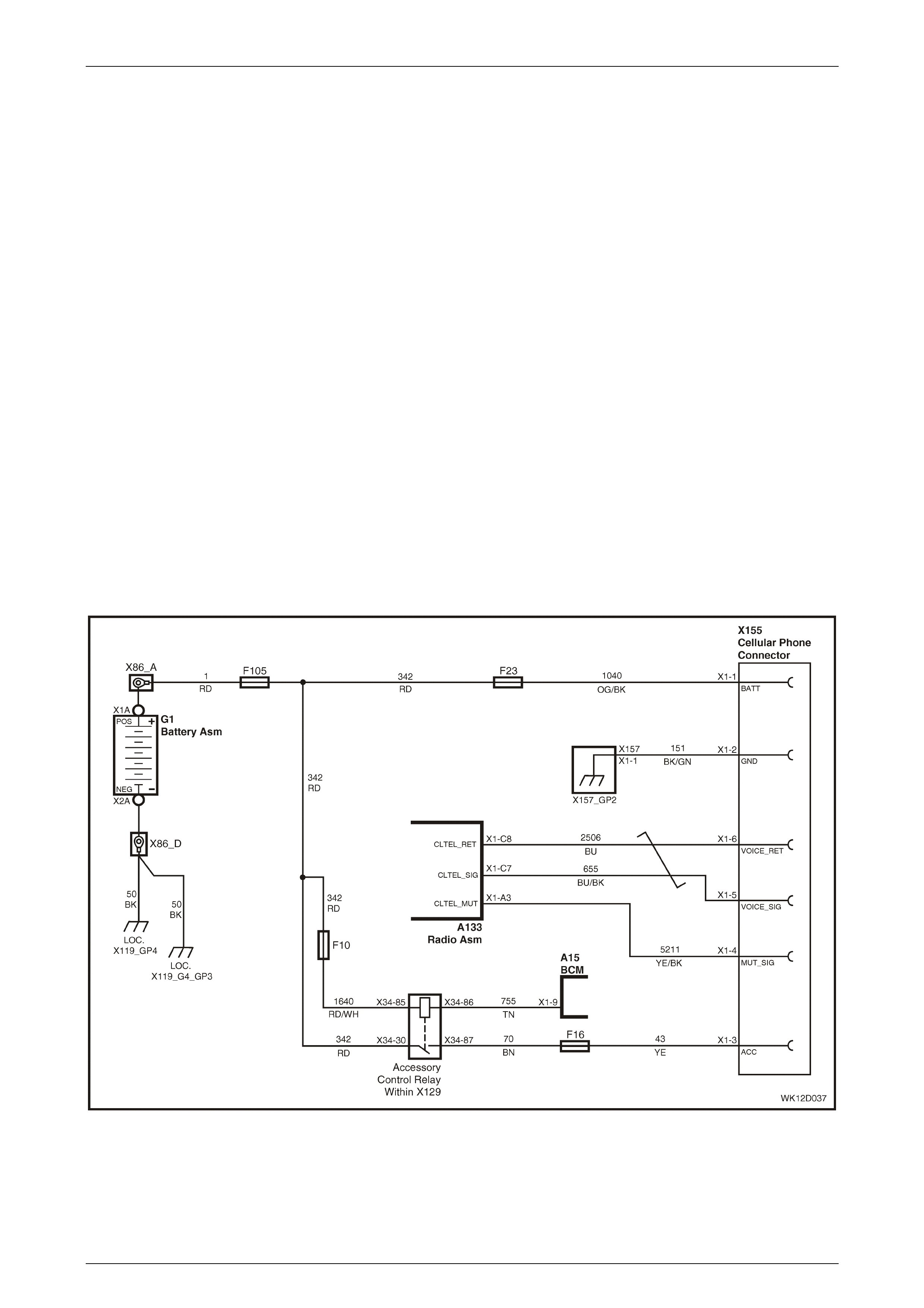
Entertainment System Page 12D–132
Page 12D–132
Hands-free Telephone Input
The Audio System has an electrical interface for a mobile telephone hands-free kit that may be used to:
• Mute the radio when a phone call is in progress.
• Play the caller’s voice through the car speakers instead of the hands-free speaker.
Using this circuit has the advantage of automatically silencing the radio or CD so the telephone can be heard without
distraction, and playing the voice through a higher power, higher quality sound system. When the voice is played through
the audio system the volume, bass and treble can be set to the best listening levels. The Independent Tone Memory will
always recall these settings when a phone call is received.
When the hands-free controller grounds the audio system mute input on terminal X1-A3, the audio system automatically
switches to Phone Mode, which is confirmed by the display showing ‘VOICE IN’. When in Phone Mode the audio system
switches to the telephone input lines on terminals X1-C8 and X1-C7. Any signal at those inputs will be played through
the audio amplifier and vehicle speakers. The inputs are high impedance, differential type that accept a wide range of
inputs from the majority of phone kits on the market. Connect the hands-free kit speaker lines direct to these terminals;
do not connect the hands-free speaker.
NOTE
Mobile phone signal quality can vary greatly
affecting the quality of the sound through the
speaker. When diagnosing phone type problems
it is recommended to move the vehicle to an area
that has a strong signal.
Figure 12D – 127 illustrates the hands-free connection for a system without Telematics, and Figure 12D – 128 illustrates
the circuit with Telematics fitted.
Hands-free Telephone Input Diagnostic Chart — Without Telematics
Figure 12D – 127

Entertainment System Page 12D–133
Page 12D–133
Hands-free Telephone Input Diagnostic Chart – Without Telematics
Step Action Value(s) Yes No
1 Was the Audio System Diagnostic Circuit Check
performed? Go to Step 2. Go to
Audio System
Diagnostic Circuit
Check
in this Section.
2 Turn the ignition on.
Switch the audio system on.
Place the mobile phone in the vehicle kit and make a
call.
Does the audio system switch to VOICE IN mode?
Go to Step 10. Go to Step 3.
3 Switch the audio system and ignition off.
Access the phone kit wiring. Refer to
Section 12G, Cellular Phone in this Service Information.
Check all phone connections for terminal retention and
that the connector is correctly located.
Are connections OK?
Go to Step 4. Repair faulty
connection.
4 Turn the ignition on.
Switch the audio system on.
Connect a digital voltmeter between the mute line at the
cellular phone in-line connector X155 terminal X1-4,
circuit 5211, and a known good ground.
Is the value as specified?
10 V or
greater Leave the digital
voltmeter
connected. Go to
Step 7.
Go to Step 5.
5 Disconnect the phone kit wiring. Refer to
Section 12G, Cellular Phone in this Service Information.
Switch the audio system on.
Connect a digital voltmeter between the mute line at the
cellular phone in-line connector X155 terminal X1-4,
circuit 5211, and a known good ground.
Is the value as specified?
10 V or
greater Go to Step 6. Go to Step 9.
6 Check that the mute line is correctly connected to the
phone kit.
Check that the voice signal and return lines are
correctly connected to the phone kit.
Are all connections OK?
Go to Step 7. Repair faulty circuit.
7 With the phone installed in the vehicle kit, make a
phone call.
Is the value as specified?
Less than
1 V Replace the audio
system head unit.
Refer to
2.1 Audio System
Head Unit
in this Section.
Go to Step 8.
8 Connect the mute line to a known good ground.
Does the audio system switch to VOICE IN mode?
Repair faulty hands-
free kit. Replace the audio
system head unit.
Refer to
2.1 Audio System
Head Unit
in this Section.

Entertainment System Page 12D–134
Page 12D–134
Step Action Value(s) Yes No
9 Remove the audio system head unit. Refer to
2.1 Audio System Head Unit in this Section.
Using a digital ohmmeter, check the continuity of the
mute line, circuit 5211, between audio head unit
connector A133 terminal X1-A3, and the mute line
cellular phone in-line connector X155 terminal X1-4.
Is the value as specified?
Continuity Replace the audio
system head unit.
Refer to
2.1 Audio System
Head Unit
in this Section.
Repair faulty
circuit 5211.
10 Adjust the phone volume and audio system volume to
approximately 50% while the call is in progress.
Does the caller’s voice play through the audio system
speakers?
Go to Step 14. Go to Step 11.
11 At the hands-free kit wiring, check that the speaker
+ wire is connected to circuit 655 and the – wire is
connected to circuit 2506.
Are the speaker wires connected correctly?
Go to Step 12. Correct wiring
connection.
12 Remove the audio system head unit. Refer to
2.1 Audio System Head Unit in this Section.
Disconnect the phone kit wiring. Refer to
Section 12G, Cellular Phone in this Service Information.
Using a digital ohmmeter, check the continuity of the
voice signal line, circuit 655, between audio head unit
connector A133 terminal X1-C7 and the cellular phone
in-line connector X155 terminal X1-5.
Using a digital ohmmeter, check the continuity of the
voice signal return line, circuit 2506, between audi o
head unit connector A133 terminal X1-C8 and the
cellular phone in-line connector X155 terminal X1-6.
Is the value as specified?
Continuity Go to Step 13. Repair faulty circuit.
13 Disconne ct circ uit 655 and cir c uit 2506 and connect a
hands-free type speaker to the hands-free controller.
Is the problem as rectified?
Permanently
installed speaker.
Audio syste m
cannot accept this
type of input.
Refer to Hands-free
Kit manufacturer for
further diagnosis .
14 Ensure that the phone volume and the audio system
volume are set at approx imate ly 50%. If either is set too
high or too low, then the sound quality may be distorted
or feedback may be heard.
Is the voice clear, with no distortion?
Go to Step 15. Adjust phone and
radio volume, radio
bass and treble until
clear sound is
produced.
15 Can digital type noise be heard when a phone call is
being made? Ensure that an
antenna system is
connected to the
phone kit and that
all connect ion s are
tight.
Confirm complaint
with customer.
WHEN ALL DIAGNOSIS AND REPAIRS ARE COMPLETED, VERIFY CORRECT OPERATION
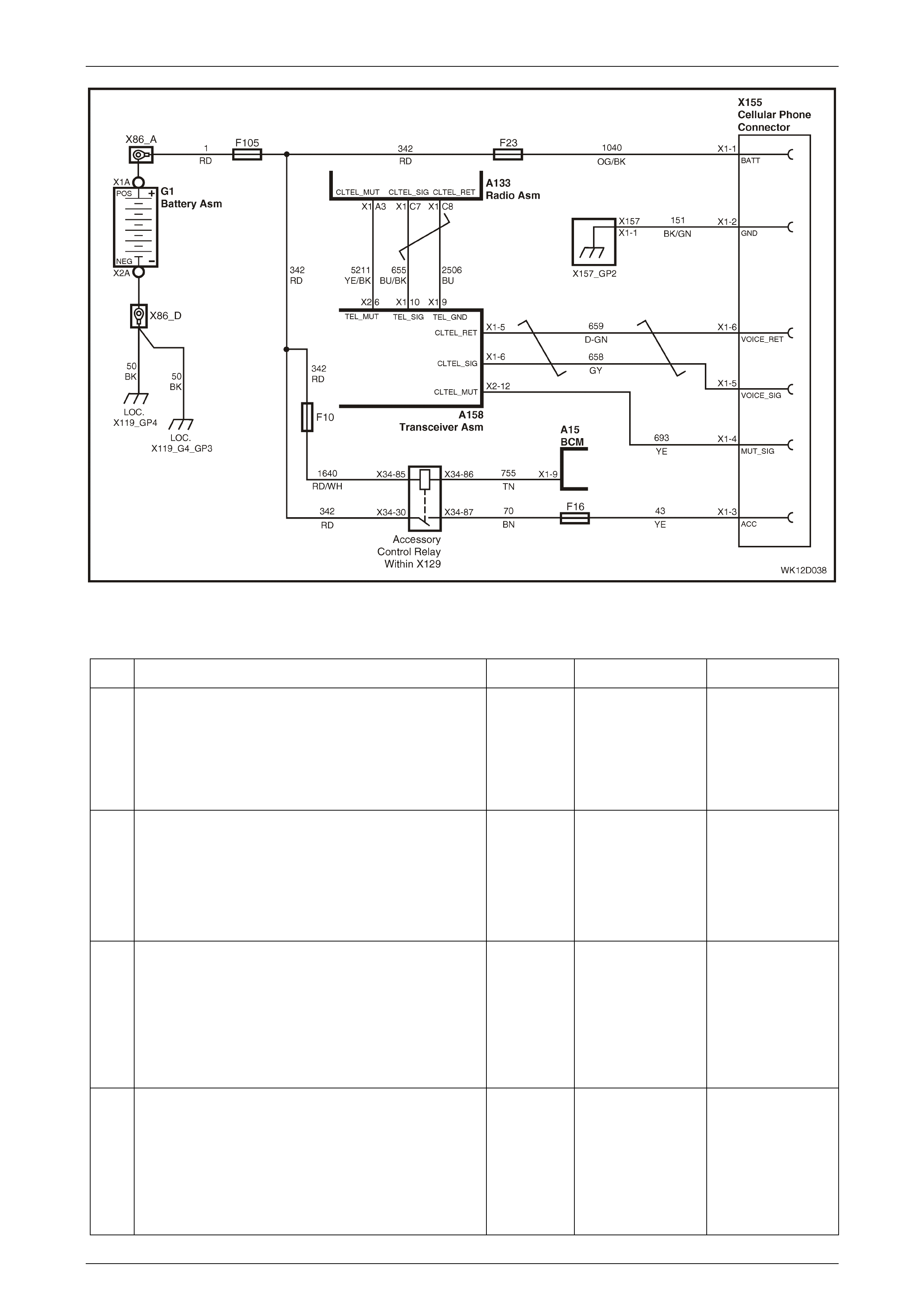
Entertainment System Page 12D–135
Page 12D–135
Figure 12D – 128
Hands-free Telephone Input Diagnostic Chart – With Telematics
Step Action Value(s) Yes No
1 Was the Audio System Diagnostic Circuit Check
performed? Go to Step 2. Go to
Audio System
Diagnostic Circuit
Check
in this Section.
2 Turn the ignition on.
Switch the audio system on.
Place the mobile phone in the vehicle kit and make a
call.
Does the audio system switch to VOICE IN mode?
Go to Step 11. Go to Step 3.
3 Switch the audio system and ignition off.
Access the phone kit wiring. Refer to
Section 12G, Cellular Phone in this Service Information.
Check all phone connections for terminal retention and
that the connector is correctly located.
Are connections OK?
Go to Step 4. Repair faulty
connection.
4 Turn the ignition on.
Switch the audio system on.
Connect a digital voltmeter between the mute line at the
cellular phone in-line connector X155 terminal X1-4,
circuit 693, and a known good ground .
Is the value as specified?
10 V or
greater Leave the digital
voltmeter
connected. Go to
Step 7.
Go to Step 5.

Entertainment System Page 12D–136
Page 12D–136
Step Action Value(s) Yes No
5 Disconnect the phone kit wiring. Refer to
Section 12G, Cellular Phone in this Service Information.
Switch the audio system on.
Connect a digital voltmeter between the mute line at the
cellular phone in-line connector X155 terminal X1-4,
circuit 693, and a known good ground .
Is the value as specified?
10 V or
greater Go to Step 6. Go to Step 9.
6 Check that the mute line is correctly connected to the
phone kit.
Check that the voice signal and return lines are
correctly connected to the phone kit.
Are all connections OK?
Go to Step 7. Repair faulty circuit.
7 With the phone installed in the vehicle kit, make a
phone call.
Is the value as specified?
Less than
1 V Replace the audio
system head unit.
Refer to
2.1 Audio System
Head Unit
in this Section.
Go to Step 8.
8 Connect the mute line to a known good ground.
Does the audio system switch to VOICE IN mode?
Repair faulty hands-
free kit. Refer to
Section 12K,
5.9 Symptoms
Chants
in the MY 2003 VY
and V2 Series
Service Information
for further diagnosis.
9 Remove the audio system head unit. Refer to
2.1 Audio System Head Unit in this Section.
Using a digital ohmmeter, check the continuity of the
mute line, circuit 5211, between audio head unit
connector A133 terminal X1-A3, and the telematics
transceiver connector A158 terminal X2-6.
Is the value as specified?
Continuity Go to Step 10. Repair faulty circuit
5211.
10 Using a digital ohmmeter, check the continuity of the
mute line, circuit 693, betw een telematics transceiver
connector A158 terminal X2-12 and the in-line
connector X155 terminal X1-4.
Is the value as specified?
Continuity Refer to Section
12K, 5.9 Symptoms
Chants in the
MY 2003 VY and V2
Series Service
Information for
further diagnosis .
Repair faulty
circuit 693.
11 Adjust the phone volume and audio system volume to
approximately 50% while the call is in progress.
Does the caller’s voice play through the audio system
speakers?
Go to Step 15. Go to Step 12.
12 At the hands-free kit wiring, check that the speaker
+ wire is connected to circuit 658 and the – wire is
connected to circuit 659.
Are the speaker wires connected correctly?
Go to Step 13. Correct wiring
connection.

Entertainment System Page 12D–137
Page 12D–137
Step Action Value(s) Yes No
13 Disconnect the Telematics. Refer to
Section 12K Telematics in the MY 2003 VY and V2
Series Service Information.
Disconnect the phone kit wiring. Refer to
Section 12G, Cellular Phone in this Service Information.
Using a digital ohmmeter, check the continuity of the
voice signal line , circuit 658, between telematic s
connector A158 terminal X1-6 and the cellular phone in-
line connector X155 terminal X1-5.
Using a digital ohmmeter, check the continuity of the
voice signal return line, circuit 659, between telemati cs
connector A158 terminal X1-5 and the cellular phone in-
line connector X155 terminal X1-6.
Is the value as specified?
Continuity Go to Step 14. Repair faulty circuit.
14 Using a digital ohmmeter, check the continuity of the
voice signal line , circuit 655, between telematic s
connector A158 terminal X1-10 and audio head unit
connector A133 terminal X1-C7.
Using a digital ohmmeter, check the continuity of the
voice signal return line, circuit 2506, between tele mati cs
connector A158 terminal X1-9 and audio head unit
connector A133 terminal X1-C8.
Is the value as specified?
Continuity Install a known good
audio system head
unit and check
operation. If fault
still persists, install
old audio system
and refer to
Section 12K
Telemat i cs
in the MY 2003 VY
and V2 Series
Service Information
for further diagnosis.
Repair faulty circuit.
15 Ensure that the phone volume and the audio system
volume are set at approx imate ly 50%. If either is set too
high or too low, then the sound quality may be distorted
or feedback may be heard.
Is the voice clear, with no distortion?
Go to Step 16. Adjust phone and
radio volume, radio
bass and treble until
clear sound is
produced.
16 Can digital type noise be heard when a phone call is
being made? Ensure that an
antenna system is
connected to the
phone kit and that
all connect ion s are
tight.
Confirm complaint
with customer.
WHEN ALL DIAGNOSIS AND REPAIRS ARE COMPLETED, VERIFY CORRECT OPERATION
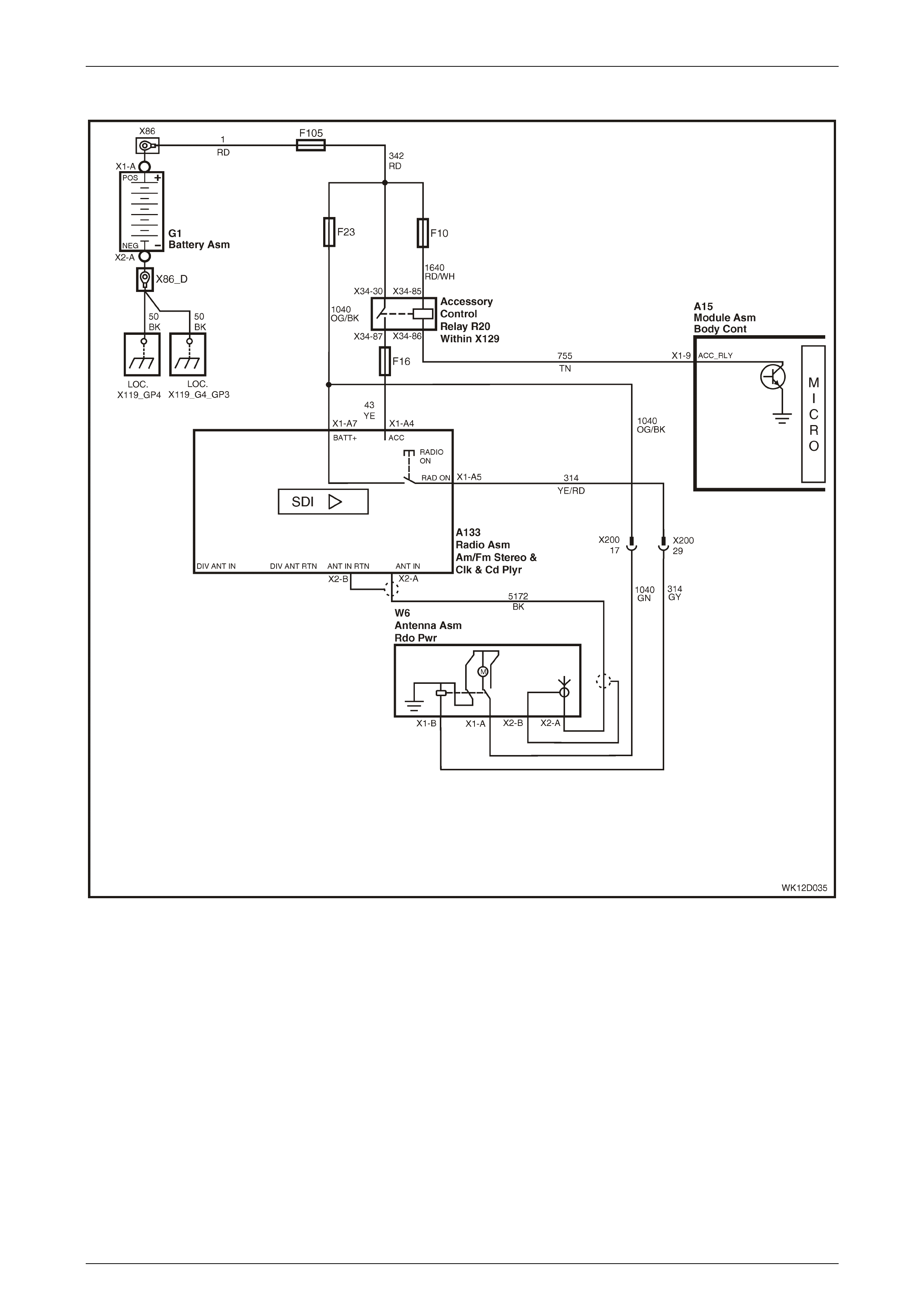
Entertainment System Page 12D–138
Page 12D–138
Electric Antenna – Full Up / Down
Figure 12D – 129
Some models are fitted with a non-adjustable, fully up or down electric antenna system. In these vehicles when the audio
system is in Radio Mode the electric antenna is fully raised. The antenna is retracted when the audio system is in CD
Mode, or turned off.
Battery voltage is applied at all times to the antenna motor via connector W6, terminal X1-A (circuit 1040), which is
protected by the RADIO fuse F23. Antenna operation is controlled from the audio system by the Radio On signal,
circuit 314, which controls the internal antenna control relay via connector W6, terminal X1-B (circuit 314).
New Audio Systems are delivered with the antenna system disabled. This is to prevent the antenna raising and
potentially becoming damaged in the Vehicle Assembly Plant. As the vehicle passes through final testing the antenna
drive is enabled and will remain enabled thereafter. In the event of an antenna system not functioning, verify that the
antenna system has been programmed correctly using TECH 2 (refer to 3.11 Program – Audio System in this Section).

Entertainment System Page 12D–139
Page 12D–139
Full Up / Down Electric Antenna Diagnostic Chart
Step Action Value(s) Yes No
1 Was the Audio System Diagnostic Circuit Check
performed? Go to Step 2. Go to
Audio System
Diagnostic Circuit
Check
in this Section.
2 Turn the audio system on.
Switch between Radio Mode and CD Mode (it may be
necessary to insert a CD).
Does the power antenna extend in Radio Mode and
retract in CD Mode?
Go to Step 14. Go to Step 3.
3 Connect TECH 2 to the DLC.
Select Diagnostics / Model Year / Vehicle Model / Body
/ Audio System / Data Display / Data List.
Scroll to Antenna Up in the TECH 2 menu.
Ensure that the audio system is turned on.
Switch between Radio Mode and CD Mode (it may be
necessary to insert a CD).
Does TECH 2 display REQUIRED in Radio Mode, and
NOT REQUIRED in CD Mode?
Go to Step 4. Enable the antenna
drive using TECH 2.
Refer to
3.11 Program –
Audio System
in this Section.
4 Remove the passenger’s side fender inner liner to gain
access to the antenna mot or. Refer to Section 1A1, 3.1
Front Wheelhouse Liner in the MY 2003 VY and V2
Series Service Information.
Check that the antenna is mounted correctly and that all
bolts and electrical connections are tight.
Check that the head of the antenna is visible through
the bezel on the fender and is not snagged on the
fender.
Check that the antenna mast is straight and not jammed
within the housing.
Are all checks OK?
Go to Step 5. Repair or replace
the antenna. Refer
to
2.7 Power Antenna
in this Section.
5 Connect a digital voltmeter between the power antenna
connector W6 terminal X1-A, circuit 1040 and a known
good ground.
Is the value as specified?
Battery
voltage Go to Step 8. Go to Step 6.
6 Disconnect the main wiring harness to body wiring
harness connector X200 (located above the BCM).
Using a digital ohmmeter, check for continuity of
circuit 1040 (Green wire), between power antenna
connector W6 terminal X1-A, and harness connector
X200, terminal 17.
Is the value as specified?
Continuity Go to Step 7. Repair faulty circuit.

Entertainment System Page 12D–140
Page 12D–140
Step Action Value(s) Yes No
7 Gain access to the instrument panel fuse and relay
panel by pulling outwards on the upper edge of the
instrument panel lower trim panel to disengage the
retaining clips .
Remove the RADIO fuse F23 from the instrument panel
fuse and relay panel.
Using a digital ohmmeter, check for continuity of
circuit 1040, betw een harn ess conn ect or X200, ter minal
17, and the output side of fuse F23.
Is the value as specified?
Continuity Check condition of
fuse and fuse holder
and repair as
necessary.
Repair faulty circuit.
8 Connect a digital voltmeter between the power antenna
connector W6 terminal X1-B, circuit 314 and a known
good ground.
Switch the audio system on and select FM Mode. Note
the voltage indication.
Switch the audio system off and note the voltage
indication.
Is the value as specified?
Radio Mode
= 10 V or
greater
Off = 0 V
Go to Step 13. Go to Step 9.
9 Remove the audio system head unit. Refer to
2.1 Audio System Head Unit in this Section.
Using a digital ohmmeter, check for continuity of circuit
314, between power antenna connector W6 terminal
X1-B, and audio head unit connector A133, terminal
X1-A5.
Is the value as specified?
Continuity Go to Step 10. Go to Step 11.
10 Ensure that Step 2 was completed.
Is the Antenna Drive enabled?
Replace the audio
system head unit.
Refer to
2.1 Audio System
Head Unit
in this Section.
Complete Step 2
and test again.
11 Disconnect the main wiring harness to body wiring
harness connector X200 (located above the BCM).
Using a digital ohmmeter, check for continuity of
circuit 314, betw een harne ss c onne ctor X200,
terminal 29, and radio connector A133 terminal X1-A5.
Is the value as specified?
Continuity Go to Step 12. Repair faulty circuit.
12 Using a digital ohmmeter, check for continuity of
circuit 314, betw een harne ss c onne ctor X200, term ina l
29, and power antenna connector W6 terminal X1-B.
Is the value as specified?
Continuity Confirm fault with
customer. Repair faulty circuit.
13 Using a digital ohmmeter, measure the resistance
between the body of the antenna motor and a known
good ground.
Is the value as specified?
Continuity Replace the
antenna. Refer to
2.7 Power Antenna
in this Section.
Repair faulty
antenna ground
circuit. Check all
attachment bolts for
tightness.
14 Does the antenna raise and lower smoothly and fully? Confirm fault with
customer. Go to Step 15.
15 Clean the antenna mast.
Does the antenna raise and lower smoothly and fully?
Confirm the repair. Replace the
antenna. Refer to
2.7 Power Antenna
in this Section.
WHEN ALL DIAGNOSIS AND REPAIRS ARE COMPLETED, VERIFY CORRECT OPERATION
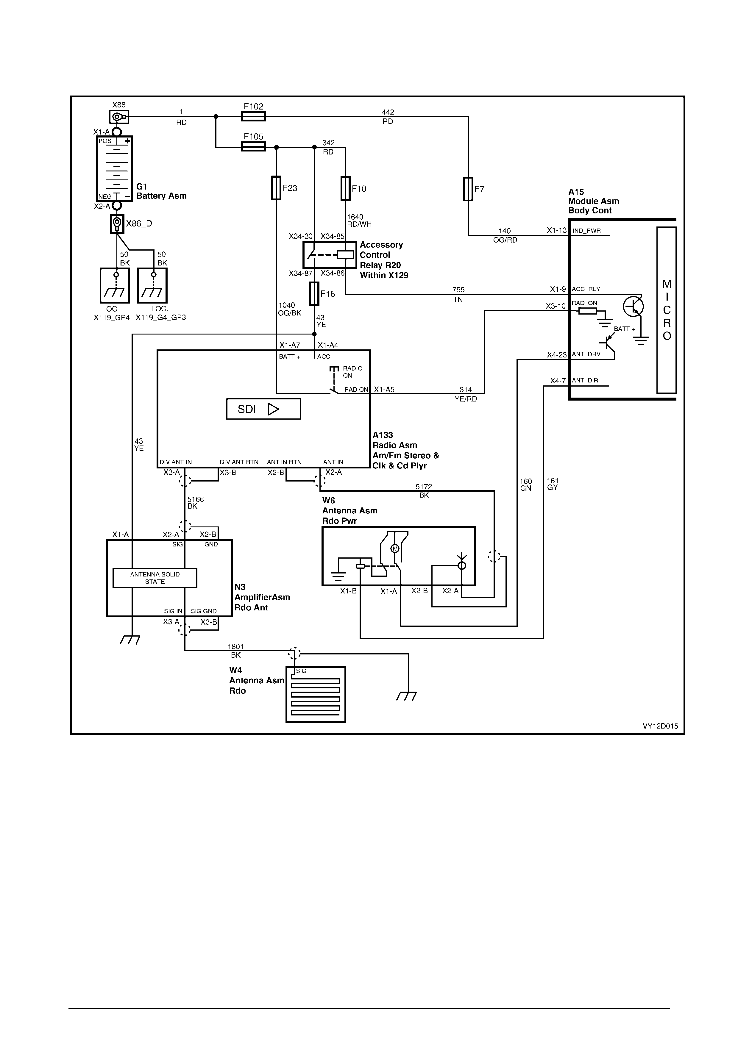
Entertainment System Page 12D–141
Page 12D–141
Electric Antenna – Height Adjustable
Figure 12D – 130
Some models are fitted with an adju stable height electric ante nna sys tem. In thes e vehicles the au dio sy stem has up and
down antenna buttons fitted. While in Radio Mode these buttons are used to raise or lower the antenna to a height that
suits the user. In CD Mode the buttons have no effect.
The adjustable height antenna is under direct control of the BCM. The audio system Radio On signal on circuit 314 is
applied to the BCM on terminal X3-10 and, together with information on the serial data bus, instructs the BCM to raise or
lower the antenna. Antenna motor power is supplied via the BCM (terminal X4-23) and is applied to the antenna
connector W6 terminal X1-A (circuit 160). Antenna direction control is also controlled by the BCM (terminal X4-7) and is
applied to the antenna connector W6 terminal X1-B (circuit 161).
New Audio Systems are delivered with the antenna system disabled. This is to prevent the antenna raising and
potentially becoming damaged in the Vehicle Assembly Plant. As the vehicle passes through final testing the antenna
drive is enabled and will remain enabled thereafter. In the event of an antenna system not functioning, verify that the
antenna system has been programmed correctly using TECH 2 (refer to 3.11 Program – Audio System in this Section).

Entertainment System Page 12D–142
Page 12D–142
Height Adjustable Electric Antenna Diagnostic Chart
Step Action Value(s) Yes No
1 Was the Audio System Diagnostic Circuit Check
performed? Go to Step 2. Go to
Audio System
Diagnostic Circuit
Check
in this Section.
2 Turn the audio system on.
Switch between Radio Mode and CD Mode (it may be
necessary to insert a CD).
Does the power antenna extend in Radio Mode and
retract in CD Mode?
Go to Step 15. Go to Step 3.
3 Connect TECH 2 to the DLC.
Select Diagnostics / Model Year / Vehicle Model / Body
/ Audio System / Data Display / Data List.
Scroll to Antenna Up in the TECH 2 menu.
Ensure that the audio system is turned on.
Switch between Radio Mode and CD Mode (it may be
necessary to insert a CD).
Does TECH 2 display REQUIRED in Radio Mode, and
NOT REQUIRED in CD Mode?
Go to Step 4. Enable the antenna
drive using TECH 2.
Refer to
3.11 Program Audio
System
in this Section.
4 Select Diagnostics / Model Year / Vehicle Model / Body
/ Body Control Module / Data Display / Inputs and
Outputs.
Scroll to Radio Status in the TECH 2 menu.
Switch between Radio Mode and CD Mode (it may be
necessary to insert a CD).
Does TECH 2 display ON in Radio Mode, and OFF in
CD Mode?
Go to Step 7. Go to Step 5.
5 Gain access to the BCM. Refer to Section 12J,
2.1 Body Control Module in the MY 2003 VY and V2
Series Service Information.
Connect a digital voltmeter between BCM module A15
connector X3-10, circuit 314, and a known good ground.
Switch the audio head unit on and select FM Mode.
Note the voltage indication.
Switch the audio head unit off and note the voltage
indication.
Is the value as specified?
Radio Mode
= 10 V or
greater
Off = 0 V
Refer to
Section 12J, 4.18
Power Antenna
Control
in the MY 2003 VY
and V2 Series
Service Information
for further
diagnostics.
Go to Step 6.
6 Remove the audio system head unit. Refer to
2.1 Audio System Head Unit in this Section.
Check for continuity of circuit 314 between the audio
system head unit P133 connector X1-A5 and BCM A15
connector X3-10, using an ohmmeter to back probe the
connectors.
Is the value as specified?
Continuity Replace the audio
system head unit.
Refer to
2.1 Audio System
Head Unit
in this Section.
Repair faulty circuit.

Entertainment System Page 12D–143
Page 12D–143
Step Action Value(s) Yes No
7 On TECH 2, select Diagnostics / Model Year / Vehicle
Model / Body / Body Control Module / Data Display /
Inputs and Outputs.
Scroll to Radio Status in the TECH 2 menu.
Turn the audio system on and select FM Mode.
Alternately press the Antenna Up and Down buttons on
the audio system fascia.
Does TECH 2 display Antenna UP and DOWN as
required?
Go to Step 8. Refer to
DTC 10 – Fascia
Button Jamme d
in this Section.
8 On TECH 2, select Diagnostics / Model Year / Vehicle
Model / Body / Body Control Module / Miscellaneous
Tests.
Scroll to Antenna in the TECH 2 menu and press the
Enter key.
Follow the test precondition prompts as detailed on the
TECH 2 screen.
Raise and lower the antenna using the TECH 2 UP and
DOWN soft keys.
Does the antenna operate correctly?
Refer to
Section 12J, 4.18
Power Antenna
Control
in the MY 2003 VY
and V2 Series
Service Information
for further
diagnostics.
Go to Step 9.
9 Remove the passenger’s side fender inner liner to gain
access to the antenna mot or. Refer to Section 1A1,
3.1 Front Wheelhouse Liner in this Service Information.
Check that the antenna is mounted correctly and that all
bolts and electrical connections are tight.
Check that the head of the antenna is visible through
the bezel on the fender and is not snagged on the
fender.
Check that the antenna mast is straight and not jammed
within the housing.
Are all checks OK?
Go to Step 10. Repair or replace
the antenna.
Refer to
2.7 Power Antenna
in this Section.
10 Connect a digital voltmeter between power antenna
connector W6 terminal X1-A, circuit 160, and a known
good ground.
Turn the audio system on.
Using the Antenna Up and Down switches on the audio
system front fascia, raise and lower the antenna.
Is the value as specified?
Battery
voltage while
raising or
lowering the
antenna
0 V at all
other times
Go to Step 12. Go to Step 11.
11 Gain access to the BCM. Refer to Section 12J,
2.1 Body Control Module in the MY 2003 VY and V2
Series Service Information.
Connect a digital voltmeter between BCM module A15
connector X4-23, circuit 160, and a known good ground.
Turn the ignition on.
Switch the audio system on and select FM Mode. Note
the voltage indication.
Using the Antenna Up and Down switches on the audio
system front fascia, raise and lower the antenna.
Is the value as specified?
Battery
voltage while
raising or
lowering the
antenna
0 V at all
other times
Repair faulty circuit. Refer to
Section 12J, 4.18
Power Antenna
Control
in the MY 2003 VY
and V2 Series
Service Information
for further
diagnostics.

Entertainment System Page 12D–144
Page 12D–144
Step Action Value(s) Yes No
12 Connect a digital voltmeter between the power antenna
connector W6 terminal X1-B, circuit 161 and a known
good ground.
Switch the audio system on and select FM Mode. Note
the voltage indication.
Using the Antenna Up and Down switches on the audio
system front fascia, raise and lower the antenna.
Is the value as specified?
Battery
voltage while
raising or
lowering the
antenna
0 V at all
other times
Go to Step 14. Go to Step 13.
13 Connect a digital voltmeter between BCM A15
connector X4-7, circuit 161, and a known good ground.
Turn the ignition on.
Switch the audio system on and select FM Mode. Note
the voltage indication.
Switch the audio system off and note the voltage
indication.
Is the value as specified?
Radio Mode
= 10 V or
greater
Off = 0 V
Repair faulty circuit. Refer to
Section 12J, 4.18
Power Antenna
Control
in the MY 2003 VY
and V2 Series
Service Information
for further
diagnostics.
14 Gain access to the antenna motor.
Using a digital mult ime t er, me asure the resist anc e
between the body of the power antenna motor and a
known good ground.
Is the value as specified?
Continuity Replace the
antenna. Refer to
2.7 Power Antenna
in this Section.
Repair the antenna
ground circuit.
15 Does the antenna raise and lower smoothly and fully? Confirm fault with
customer. Go to Step 16.
16 Clean the antenna mast.
Does the antenna raise and lower smoothly and fully?
Confirm the repair. Replace the
antenna. Refer to
2.7 Power Antenna
in this Section.
WHEN ALL DIAGNOSIS AND REPAIRS ARE COMPLETED, VERIFY CORRECT OPERATION

Entertainment System Page 12D–145
Page 12D–145
Single CD Player
The WK Level 1 standard audio system features a single CD player. The CD is inserted into the CD player through the
slot on the fascia above the display. Unlike the models with CD Changer, the CD is loaded by pushing it into the CD slot
until the mechanism senses the CD and automatically loads it into the playing position.
The CD player will play all commercially recorded 120 mm music CDs, and most CDRs that have been recorded using
good quality CD Writers. CD-RWs may not play satisfactorily.
The CD Player will not play non-standard sized CDs, eg 80 mm CDs. Using CDs smaller than 120 mm even with an
adaptor may result in damage to the CD, CD player or both.
Foreign objects, eg credit cards, placed in the CD slot will prevent loading and unloading of CDs.
Loading two CDs at once will jam the mechanism.
The CD Player cannot decode files recorded in compressed format, eg MP3.
CDs should not have labels attached to them. The label may peel off or buckle due to heat and rub or jam the CD
mechanism. Damage caused by these labels is not covered under warranty.
The CD mechani sm is a high qual ity unit with mechanical shock absorbers. There is no electronic anti- sk ip mem ory
buffer fitted, therefore the CD player may skip when given a sharp jolt, for example hitting a large pothole while driving.
Under normal circumstances the CD player will resume playback within one second of the shock. No damage to the CD
mechanism or CD should occur during the skip.
NOTE
CD DOES NOT EJECT In cases where fascia
button damage or no operation prevents a
customer’s CD from being ejected, use the
TECH 2 to remove the CD prior to returning the
unit for repair (refer to 3.10 Miscellan eous Tests
– Audio System in this Section). W here this is not
possible and the unit is returned for repair with a
customer’s CD trapped inside, attach a note to
the Exchange Request form detailing:
• Name of CD (for example Carmina Burana).
• Owner’s name.
• Owner’s mailing address, or Holden Retailer's
address – if CD is to be returned to the
customer by the Holden Retailer.
• Contact name and telephone number within
the Holden Retailer.
It is recommended that the audio s ystem head
unit does not contain a CD when being
removed or installed. Under some
circumstances, a CD may become dislodged
it the unit is treated roughly during removal or
installation.

Entertainment System Page 12D–146
Page 12D–146
Single CD Player Diagnostic Chart
Step Action Value(s) Yes No
1 Was the Audio System Diagnostic Circuit Check
performed? Go to Step 2. Go to
Audio System
Diagnostic Circuit
Check
in this Section.
2 Turn on the audio system, select Radio Mode and tune
to a strong station.
Does the system work as expected in Radio Mode?
Go to Step 3. Diagnose other
system related
problems first.
3 Switch to CD Mode.
Load a CD (if necessary), label facing upwards.
Eject the CD.
Does CD load and eject smoothly and quietly?
Go to Step 4. Replace the audio
system head unit.
Refer to
2.1 Audio System
Head Unit
in this Section.
4 Load the CD, label facing upwards.
Does the CD play correctly without interruption?
NOTE
Verify the CD plays correctly on another unit
before deciding to replace the audio head
unit.
Go to Step 5. Replace the audio
system head unit.
Refer to
2.1 Audio System
Head Unit
in this Section.
5 With the CD playing, test drive the vehicle and note if
the CD skips over average road surfaces.
Is the performance as expected?
NOTE
This test must be performed with a CD in
good condition. Dirty or badly scratched CDs
will skip much easier due to the poor laser
signal received from them.
Verify fault with
customer. Go to Step 6.
6 Remove the audio system head unit. Refer to
2.1 Audio System Head Unit in this Section.
Check that the audio head unit cradle and surrounding
escutcheon are securely held in place by their retaining
screws.
Is the assembly securely mounted?
Replace the audio
system head unit.
Refer to
2.1 Audio System
Head Unit
in this Section.
Repair as
necessary.
WHEN ALL DIAGNOSIS AND REPAIRS ARE COMPLETED, VERIFY CORRECT OPERATION

Entertainment System Page 12D–147
Page 12D–147
CD Changer
The VY System 3 and W K System 3a, System 4 and System 6 audio systems feature an integrated six-disc CD Changer
built into the audio system head unit. CDs are loaded and ejected one at a time through the single slot on the fascia.
Display messages, audible beeps and flashing of the fascia LED co-ordinate the loading and removal of CDs. A seven
second memory is fitted to prevent music interruption due to strong vibration.
The CD Changer will play all commercially recorded 120 mm mu sic CDs, and most CDRs that have been recorded using
good quality CD Writers. CD-RWs may not play satisfactorily. The CD Changer will not play non-standard sized CDs, eg
80 mm CDs. Using CDs smaller than 120 mm even with an adaptor may result in damage to the CD, CD Changer or
both.
The CD Changer uses a LOAD button on the fascia to start the loading process. Pushing CDs into the CD slot will not
cause automatic loading and may cause the mechanism to jam.
Foreign objects, eg credit cards, placed in the CD slot will prevent loading and unloading of CDs.
Loading two CDs at once will jam the mechanism.
The CD Changer cannot decode files recorded in compressed format, eg MP3.
CDs should not have labels attached to them. The label may peel off or buckle due to heat and rub or jam the CD
mechanism. Damage caused by these labels is not covered under warranty.
NOTE
CD DOES NOT EJECT In cases where fascia
button damage or no operation prevents a
customer’s CD from being ejected, use the
TECH 2 to remove the CD prior to returning the
unit for repair (refer to 3.10 Miscellan eous Tests
– Audio System in this Section). W here this is not
possible and the unit is returned for repair with a
customer’s CDs trapped inside, attach a note to
the Exchange Request form detailing:
• Name of CDs (for example Carmina Bura na).
• Owner’s name.
• Owner’s mailing address, or Holden Retailer's
address – if CD is to be returned to the
customer by the Holden Retailer.
• Contact name and telephone number within
the Holden Retailer.
It is recommended that the audio s ystem head
unit does not contain any CDs when being
removed or installed. Under some
circumstances, a CD may become dislodged
it the unit is treated roughly during removal or
installation.
CD Changer Diagnostic Chart
Step Action Value(s) Yes No
1 Was the Audio System Diagnostic Circuit Check
performed? Leave TECH 2
connected. Go to
Step 2.
Go to
Audio System
Diagnostic Circuit
Check
in this Section.
2 Turn on the audio system, select Radio Mode and tune
to a strong station.
Does the system work as expected in Radio Mode?
Go to Step 3. Diagnose other
system related
problems first.

Entertainment System Page 12D–148
Page 12D–148
Step Action Value(s) Yes No
3 Does the display show that any CD’s are loaded? This
will be confirmed by numbers inside the circles at the
bottom of the display at the MFD.
Press CD button.
Go to Step 6. Go to Step 4.
4 Press the LOAD button.
Does the CD player make normal loading noises and
request a CD after a few seconds?
Go to Step 5. Record any DTCs
and eject the CDs.
Replace the audio
system head unit.
Refer to
2.1 Audio System
Head Unit
in this Section.
5 Load the CD.
Does the CD load smoothly and quickly?
Go to Step 6. Replace the audio
system head unit.
Refer to
2.1 Audio System
Head Unit
in this Section.
6 Does the CD play normally? Press the CD button if
necessary.
NOTE
Verify the CD plays correctly on another unit
before deciding to replace the CD player.
Go to Step 7. Record any DTCs
and eject the CDs.
Replace the audio
system head unit.
Refer to
2.1 Audio System
Head Unit
in this Section.
7 Is exc ess ive noise coming from the mechanism? R ecord any DTCs
and eject the CDs.
Replace the audio
system head unit.
Refer to
2.1 Audio System
Head Unit
in this Section.
Go to Step 8.
8 Using the TRACK>> button step through the tracks on
the CD stopping at each briefly to confirm correct
playback.
Does each track play properly?
NOTE
Verify the CD plays correctly on another unit
before deciding to replace the CD player.
Go to Step 9. Record any DTCs
and eject the CDs.
Replace the audio
system head unit.
Refer to
2.1 Audio System
Head Unit
in this Section.
9 Load and play a second CD, or select another if one is
already loaded.
Using the TRACK>> button step through the tracks on
the CD stopping at each briefly to confirm correct
playback.
Does the operation complete successfully?
Go to Step 10. Record any DTCs
and eject the CDs.
Replace the audio
system head unit.
Refer to
2.1 Audio System
Head Unit
in this Section.
10 Repeat Step 9 until six CDs have been loaded and
tested.
Did the operation finish successfully?
Go to Step 11. Record any DTCs
and eject the CDs.
Replace the audio
system head unit.
Refer to
2.1 Audio System
Head Unit
in this Section.

Entertainment System Page 12D–149
Page 12D–149
Step Action Value(s) Yes No
11 Eject, load and briefly play each CD again.
Were any errors encountered?
Record any DTCs
and eject the CDs.
Replace the audio
system head unit.
Refer to
2.1 Audio System
Head Unit
in this Section.
Go to Step 12.
12 Put the CD player into DISC RANDOM mode.
Set the volume to a medium level.
Allow to play unattended for one hour or more.
Were any errors encountered that stopped playback?
Record any DTCs
and eject the CDs.
Replace the audio
system head unit.
Refer to
2.1 Audio System
Head Unit
in this Section.
Go to Step 13.
13 With a CD playing, test drive the vehicle on smooth and
rough roads and note if any errors occur. Change the
CD several times during the test.
Were any abnormalities noted?
Record DTCs and
eject the CDs.
Replace the audio
system head unit.
Refer to
2.1 Audio System
Head Unit
in this Section.
Verify fault with
customer.
WHEN ALL DIAGNOSIS AND REPAIRS ARE COMPLETED, VERIFY CORRECT OPERATION
Radio Reception
The audio system has a sophisticated radio tuner. Primary emphasis is on consistent sound quality without the effects of
external interference. The AM section has good sensitivity for weak stations and strong selectivity to prevent interference
from other stations. FM includes a multipath detection circuit to stop unwanted noise being amplified and a treble cut
circuit to reduce noise when signals are weak. The circuit is under continuous computer control to adjust its
characteristics as reception conditions vary. Apart from Local (LOC) and Distance (DX) search switching there are no
user adjustable parameters.
With TECH 2 it is possible to monitor the signal strength received by the radio. This is a good tool for diagnosing radio
and antenna problems. On models fitted with a diversity antenna, TECH 2 may be used to switch between the front
antenna and the diversity antenna for diagnostic purposes.
The diversity antenna system is used to minimise the normal disturbances associated with FM transmissions. Using the
two antennas the radio monitors the signal from both antennas and dynamically selects the antenna with the better
signal. Compared to a standard single antenna, this achieves a more even sound quality without the frequent
disturbances of a single antenna design. Refer to the Diversity Antenna Fa ult D iagnosis in this Section for details and
diagnosis of the Diversity Antenna.
Multipath Detector
The audio system has a special circuit to detect the presence of multipath in the FM signal. W hen multipath is detected,
the tuner switches to mono output mode so that the multipath distortion is not heard. The computer requires several
seconds of multipath free reception before it will allow the output to return to full stereo. Due to this circuitry, the radio will
sometimes be in mono reception mode during city and urban driving where multipath is most common. The delay in
switching from mono to stereo is to reduce the effects of the music suddenly switching modes. Switching between mono
and stereo is often perceived as a volume change. In some cases the customer will notice the volume fluctuation,
particularly if a high value of treble has been selected in the audio setting.
Treble Control
When signals become weaker the background noise seems to become stronger. The background noise in fact remains
constant but the radio station is not strong enough to overcome it. In these circumstances the radio automatically
reduces the amount of treble (called High Frequency Cut) to help hide the background noise. On Level 2 to 5 audio head
units the High Frequency Cut is partially selectable with the LOCAL function. When in LOCAL mode, there is no High
Frequency Cut. In non-LOCAL Mode or Distance Mode, the treble is reduced by half to cut down on the background
noise. It is recommended to leave the LOCAL on to achieve the best performance from local radio stations.

Entertainment System Page 12D–150
Page 12D–150
NOTE
When performing radio diagnosis it is
recommended that the vehicle be moved outside
the workshop. Radio signals are blocked by the
metal structure of most workshops making testing
difficult. AM particularly is affected by being in an
enclosed space. Radio reception varies
significantly with location. When testing for radio
performance it is advisable to have another car
available for a comparison check.
Vehicle interference is often caused by a bad earth connection within the vehicle. To isolate the source of interference
turn circuits on and off until the source of the noise is found, eg indicators, wipers, horn. Then study the circuit diagram
paying attention to the location of earth points (refer to Section 12P, Wiring Diagrams in this Service Information). Check
each earth point for tightness and ensure that mating surfaces are free from corrosion.
Radio Reception Diagnostic Chart
Step Action Value(s) Yes No
1 Was the Audio System Diagnostic Circuit Check
performed? Go to Step 2. Go to
Audio System
Diagnostic Circuit
Check
in this Section.
2 Move the vehicle to an outside location that is known to
have good reception.
Ensure that the audio head unit is installed in the
instrument panel correctly. If the audio head unit is not
fully installed, connection to the antenna lead will be
affected.
Switch the audio system on.
Ensure that the antenna is full y extended.
Is the antenna damaged or not extending properly?
Refer to
Electric Antenna –
Full Up/Down
or
Electric Antenna –
Height Adjustable
Diagnosis
in this Section.
If vehicle is a
Level 1 to 3, go to
Step 3.
If vehicle is a
Level 4 or 5, go to
Step 4.
3 If possible, select a local FM station.
Connect TECH 2 to the DLC.
Select Diagnostics / Model Year / Vehicle Model / Body
/ Audio System / Data Display / Data List.
Scroll to Antenna Signal Strength in the TECH 2 menu.
Can the signal strength be made to read 60 or more? If
necessary move the vehicle to find a better signal.
Go to Step 13. Go to Step 6.
4 If possible, select a local FM station.
Connect TECH 2 to the DLC.
On TECH 2, select Diagnostics / Model Year / Vehicle
Model / Body / Audio System / Data Display / Data List.
Scroll to Antenna Signal Strength in the TECH 2 menu.
Switch between the main and diversity antennas using
the TECH 2 soft keys.
Drive the vehicle in a small circle while monitoring the
main and diversity antenna signal strengths.
Is the displayed signal strength within 20 for each
antenna and above 40?
Go to Step 13. Go to Step 5.

Entertainment System Page 12D–151
Page 12D–151
Step Action Value(s) Yes No
5 Is the diversity antenna signal strength always about
30 units below the main antenna signal strength? Go to
2.8 Diversity
Antenna – Test
Procedure
in this Section.
Go to Step 6.
6 Remove the audio system head unit. Refer to
2.1 Audio System Head Unit in this Section.
Check that the antenna connector is plugged into the
audio head unit cradle properly.
From inside the vehicl e, remove the passenger’s side
hinge pillar trim assembly to gain access to the antenna
connector. Refer to Section 1A8 Headlining and Interior
Trim in this Service Information. Check that the antenna
extension lead is correctly connected to the front
antenna lead.
Install the audio system head unit. Refer to
2.1 Audio System Head Unit in this Section.
Switch the audio system on.
Has the signal strength improved?
Go to Step 13. Go to Step 7.
7 Remove the audio system head unit. Refer to
2.1 Audio System Head Unit in this Section.
Using a digital ohmmeter, measure the resistance at
audio head unit connector A133 between terminal X1-
A8, circuit 851 and a known good ground.
Is the value as specified?
Less than
1 ohm Go to Step 8. Repair faulty
circuit 851.
8 Using a digital ohmmeter, measure the resistance
between body ground and the centre terminal of the
main antenna lead.
Is the value as specified?
Open circuit,
or greater than
100 M egohms
Go to Step 9. Replace damaged
antenna. Refer to
2.7 Power Antenna
in this Section, or
replace damaged
antenna extension
lead. Refer to
Section 12O Radio
Power Antenna
Assembly
wiring diagram in
this Service
Information for
further details.
9 Using a digital ohmmeter, measure the resistance
between the body ground and the outer metal spring
connections of the main antenna lead.
Is the value as specified?
Less than
1 ohm Go to Step 10. Repair faulty ground
connection.
10 Disconnect the antenna extension lead from the
antenna lead connector.
Using a digital ohmmeter, check continuity of the
antenna extension lead centre conductor from the audio
head unit connector A133 terminal X2-A, circuit 5172 to
the other end of the extension lead.
Is the value as specified?
Less than
1 ohm Reinstall antenna
lead. Go to Step 11. Replace antenna
extension lead. For
extension lead
installation and
routing refer to
Section 12O Radio
Power Antenna
Assembly
wiring diagram in
this Service
Information for
details.

Entertainment System Page 12D–152
Page 12D–152
Step Action Value(s) Yes No
11 If possible, remove suspect audio head unit and install
in another vehicle. If not available go to Step 12.
Has reception improved?
Replace the audio
system head unit.
Refer to
2.1 Audio System
Head Unit
in this Section.
Refer to
Electric Antenna –
Full Up/Down
or
Electric Antenna –
Height Adjustable
diagnosis in this
Section.
12 Temporarily fit a substitute front antenna.
Has reception improved?
Install new main
antenna. Refer to
2.7 Power Antenna
in this Section.
Replace the audio
system head unit.
Refer to
2.1 Audio System
Head Unit
in this Section.
13 Choose AM and tune to a weak station.
Confirm expected sound quality on another vehicle at
the same location.
Turn the ignition off (if it was on).
From the Body Menu, select Audio System / Data
Display / Data List on TECH 2.
Scroll to Antenna Signal Strength in the TECH 2 menu.
Note the signal strength and sound quality.
Turn the ignition on (do not start engine) and operate
electrical items in the vehicle – wipers, indicators, fan,
lights etc.
Has the sound quality reduced significantly by turning
the ignition on?
Check for poor
ground connections.
Isolate the cause by
switching circuits on
and off. Repair
faulty circuit.
Go to Step 14.
14 Start the engine.
Has the sound quality reduced significantly by starting
the engine?
Go to Step 15. Go to Step 16.
15 Operate the engine throttle to increase the engine
speed.
Does the interference change frequency with changes
in engine speed?
Check charging, fuel
and ignition system
for bad electrical
connections.
Check the electronic
modules and motors
for poor
connections, eg,
starter motor and
PCM.
16 Move the vehicle.
Does the level of interference also change, i.e.
interference is external?
Compare with
another similar
vehicle. If the
performance is
similar, the
interference is
caused by ex ternal
sources and cannot
be overcome.
Replace the audio
system head unit.
Refer to
2.1 Audio System
Head Unit
in this Section.
WHEN ALL DIAGNOSIS AND REPAIRS ARE COMPLETED, VERIFY CORRECT OPERATION
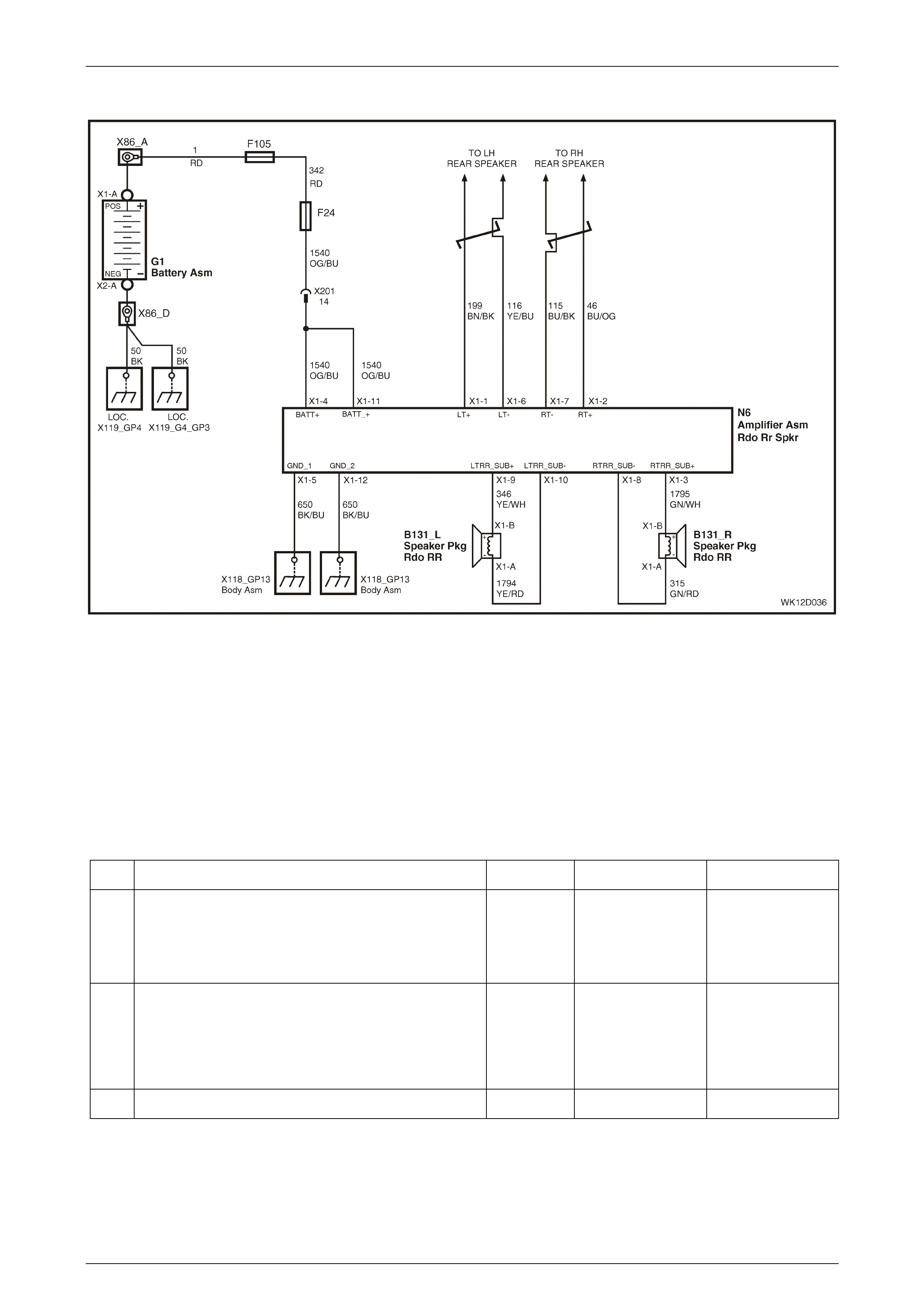
Entertainment System Page 12D–153
Page 12D–153
Subw oofer Amplifier
Figure 12D – 131
Level 4 vehicles are fitted with an auxiliary amplifier to improve the low frequency output of the system using two parcel
shelf mounted subwoofer speakers. The unit is a two channel, high powered design that features self-protection circuitry
to stop overload in the event of damage to wiring or speakers, or high temperatures. Signal inputs to the amplifier are
taken from the corresponding left and right rear door speakers, as per the system diagram, and the signals are then
combined to produce a mono output.
Output gain can be varied by turning the small adjuster mounted on the end of the casing at the opposite end to the
connector. The centre position is the default setting. From the centre position the subwoofer effect can be increased by
6 dB or decreased by 3 dB from the factory setting for customers who prefer more or less subwoofer effect. A 10 Amp
fuse mounted in the end of the unit will protect the wiring in event of an internal amplifier failure.
Subwoofer Amplifier Diagnostic Chart
Step Action Value(s) Yes No
1 Was the Audio System Diagnostic Circuit Check
performed? Go to Step 2. Go to
Audio System
Diagnostic Circuit
Check
in this Section.
2 Switch the audio system on, increase bass to
maximum, fade speakers to the rear, set balance to
STD, and adjust the volume to a medium level.
Can you hear the subwoofer system operating from
inside the vehicle or in the rear compartment?
Go to Step 7. Go to Step 3.
3 Are the corresponding rear door speakers operating? Go to Step 5. Go to Step 4.

Entertainment System Page 12D–154
Page 12D–154
Step Action Value(s) Yes No
4 Check the door speaker wiring for an open circuit or
short circuit and repair as necessary. Refer to
No Sound or Distorted Sound Diagnostic Chart in
this Section.
Test the audio system again as detailed in Step 2.
Is the system working?
Return audio
system settings to
normal. Go to
Step 10.
Go to Step 5.
5 Remove the subwoofer amplifier, refer to
2.10 Subwoofer Amplifier in this Section.
Check the 10 A fuse located at end of the unit. Replace
if necessary.
Check the wiring connection on the subwoofer amplifier
wiring harness. Repair as necessary.
Using a digital voltmeter, check for battery voltage
between the following terminals of amplifier connector
N6 and a known good ground. Repair as necessary:
• Terminal X1-4, circuit 1540.
• Terminal X1-11, circuit 1540.
Using a digital ohmmeter, check for continuity between
a known good ground and the following terminals of
amplifier connector N6. Repair as necessary:
• Terminal X1-5, circuit 650.
• Terminal X1-12, circuit 650.
Install the amplifier (refer to 2.10 Subwoofer Amplifier in
this Section) and test the audio system again as
detailed in Step 2.
Is the system working?
End of diagnostics. Go to Step 6.
6 Check the wiring connections on the subwoofer
speakers for damage or incorrect connection. Repair as
necessary.
Using a digital ohmmeter, check for open circuit
between each of the speaker circuits and a known good
ground at amplifier connector N6. Repair as necessary.
Test the audio system again as detailed in Step 2.
Is the system working?
End of diagnostics. Go to Step 7.
7 Disconnect the subwoofer amplifier connector N6.
Ensure that each subwoofer speaker connector is firmly
connected to its speaker. Using a digital ohmmeter,
check for continuity between each of the speaker
circuits at amplif ier conn ector N6.
• Left Speaker – X1-9, circuit 346 and X1-10, circuit
1794.
• Right Speaker – X1-3, circuit 1795 and X1-8,
circuit 315.
Is the value as specified?
Approximately
2 ohms Replace the
subwoofer amplifier.
Refer to
2.10 Subwoofer
Amplifier
in this Section.
Go to Step 8.
8 Disconnect the subw oofer speaker connector on the
speaker that gives the faulty reading.
Using a digital ohmmeter, check for continuity between
the speaker terminals.
Is the value as specified?
Approximately
2 ohms Go to Step 9. Replace the
subwoofer spea ker.
Refer to
2.5 Subwoofer
Speakers – Level 4
and 5 Vehicles
in this Section.

Entertainment System Page 12D–155
Page 12D–155
Step Action Value(s) Yes No
9 Repair open or short circuit in speaker wiring circuits
346, 1794, 315 or 1795 as appropriate.
Install the amplifier and speakers and test the audio
system again as detailed in Step 2.
Is the system working?
End of diagnostics. Replace the
subwoofer amplifier,
refer to
2.10 Subwoofer
Amplifier
in this Section.
10 Are both speakers working equally and free from
unusual vibrations, buzzes or distortion? Verify fault with
customer. Go to Step 11.
11 Check the speaker cone for foreign materials, such as
screws, stones or wiring.
Verify the sealing foam on the parcel shelf is seated
correctly and not touching the speaker cone. Repair as
necessary.
Verify the parcel shelf is tightly mounted and not free to
vibrate.
Test the audio system again as detailed in Step 2.
Is the system working as expected?
End of diagnostics. Replace the
subwoofer spea ker.
Refer to
2.5 Subwoofer
Speakers – Level 4
and 5 Vehicles
in this Section.
WHEN ALL DIAGNOSIS AND REPAIRS ARE COMPLETED, VERIFY CORRECT OPERATION

Entertainment System Page 12D–156
Page 12D–156
DTC 10 – Fascia Button Jammed
With the ignition in either the Accessories position or the On position, DTC 10 will set if a audio head unit fascia panel
control button remains pressed or stuck for more than 40 seconds.
Fascia Button Jammed Diagnostic Chart
Step Action Value(s) Yes No
1 Was the Audio System Diagnostic Circuit Check
performed? Go to Step 2. Go to
Audio System
Diagnostic Circuit
Check
in this Section.
2 Check the fascia and every button for signs of damage,
foreign objects, poor or sticking operation. Check the
escutcheon surrounding the audio head unit is not
distorted and exerting pressure on the fascia.
Is there damage or foreign objects present to cause the
problem?
Go to Step 3. Go to Step 4.
3 Clear any objects and clean any residue.
Does the button function correctly?
End of diagnostics. Replace the audio
system head unit.
Refer to
2.1 Audio System
Head Unit
in this Section.
4 Check the stuck button for signs of poor operation.
Does the button stick for no apparent reason?
Replace the audio
system head unit.
Refer to
2.1 Audio System
Head Unit
in this Section.
Go to Step 5.
5 Connect TECH 2 to the DLC.
Select Diagnostics / Model Year / Vehicle Model / Body
/ Audio System / Diagnostic Trouble Codes / Clear DTC
Information.
Press all buttons several times.
Allow the radio to operate for several minutes. Do not
press any buttons during this time.
Does the DTC set again?
Replace the audio
system head unit.
Refer to
2.1 Audio System
Head Unit
in this Section.
Verify fault with
customer.
WHEN ALL DIAGNOSIS AND REPAIRS ARE COMPLETED, CLEAR ALL DTCs AND VERIFY CORRECT
OPERATION
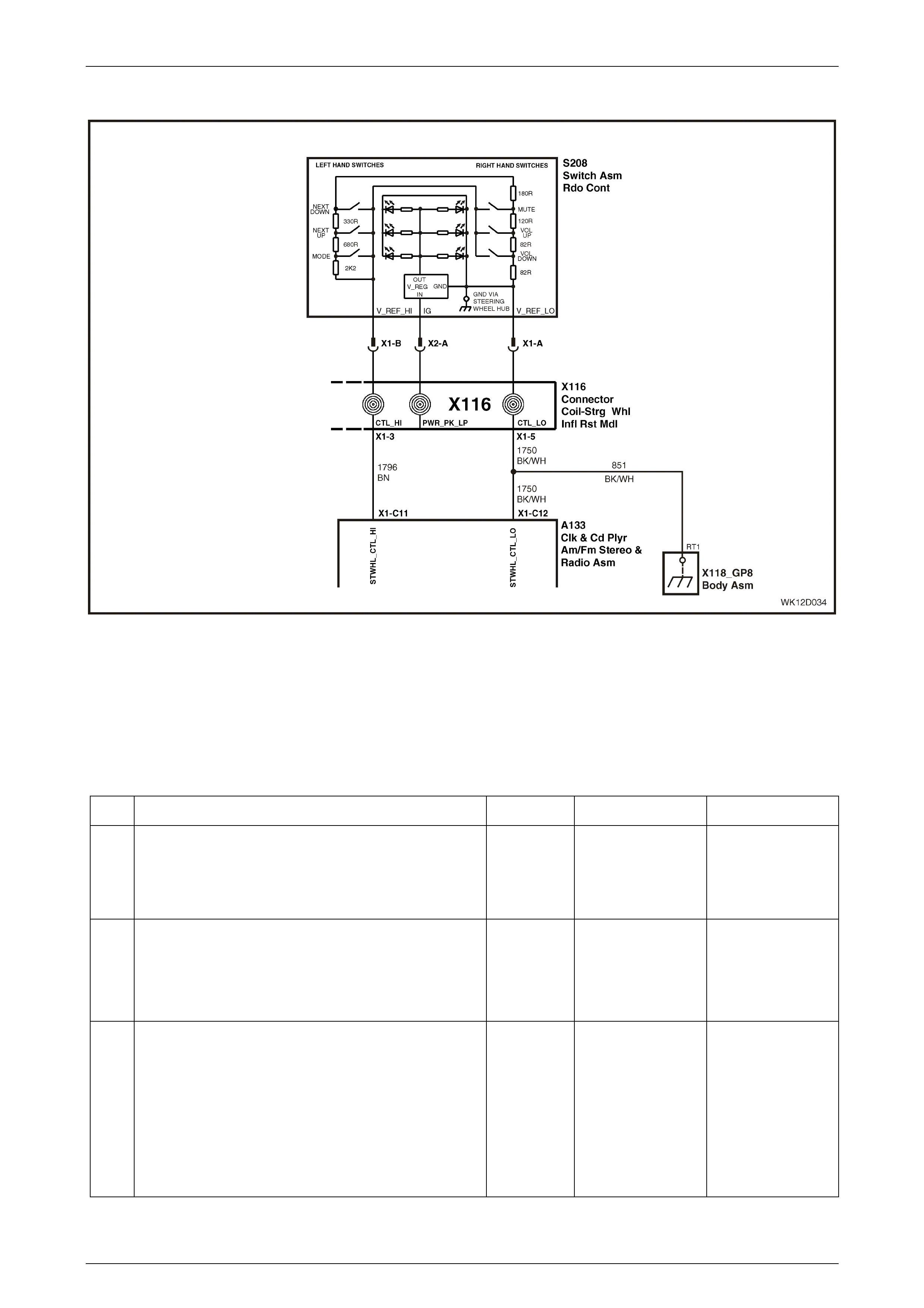
Entertainment System Page 12D–157
Page 12D–157
DTC 11 – Steering Wheel Remot e Button Jammed
Figure 12D – 132
Control buttons located on the steering wheel provide remote operation of various audio system functions. The remote
controls constitute a resistive network. When a button is pressed, the change in resistance is interpreted by the audio
head unit as a button press, and the appropriate function is actioned.
With the ignition in either the Accessories position or the On position, DTC 11 will set if a steering wheel control button
remains presse d or stuck f or more than 30 sec ond s.
Steering Wheel Remote Controls Diagnostic Chart
Step Action Value(s) Yes No
1 Was the Audio System Diagnostic Circuit Check
performed? Go to Step 2. Go to
Audio System
Diagnostic Circuit
Check
in this Section.
2 Switch the audio head unit on.
Press each of the steering wheel remote control buttons
and note if the unit follows the command.
Does the audio system operate as expected?
Confirm fault with
customer. Go to Step 3.
3 Connect TECH 2 to the DLC.
Select Diagnostics / Model Year / Vehicle Model / Body
/ Audio System / Data Display / Data List.
Scroll to Steering Wheel Remote Control in the TECH 2
menu.
Do not press any button.
Does TECH 2 display KEY RELEASED?
Go to Step 4. Go to Step 5.

Entertainment System Page 12D–158
Page 12D–158
Step Action Value(s) Yes No
4 Press each of the steering wheel remote control buttons
in turn.
Does TECH 2 display the name of each button when
pressed?
Go to Step 8. Go to Step 6.
5 Remove the audio head unit. Refer to
2.1 Audio System Head Unit in this Section.
Using a digital ohmmeter, measure the resistance at
audio head unit connector A133 between terminal X1-
C11, circuit 1796 and termina l X 1-C 12, circuit 1750.
Do not press any button.
Is the resistance as specified?
Between
3.5 kohms
and
3.9 kohms
Go to Step 7. Repair faulty circuit
1796 or 1750.
6 With the ohmmeter connected as in Step 5, press and
hold the MUTE button.
Is the resistance as specified?
Between
270 ohms
and
300 ohms
Go to Step 7. Replace steering
wheel rem ote
controls. Refer to
2.9 Horn Bar
Stereo Controls
in this Section.
7 Using a digital ohmmeter, measure the resistance at
audio head unit connector A133 between terminal X1-
C11, circuit 1796 and a known good ground.
Using a digital ohmmeter, measure the resistance at
audio head unit connector A133 between terminal X1-
C12, circuit 1750 and a known good ground.
Is the resistance as specified?
Open circuit Go to Step 8. Repair faulty circuit
1796 or 1750.
8 Turn the headlamp switch to the Park position.
Using a digital ohmmeter, measure the resistance at
audio head unit connector A133 between terminal X1-
C11, circuit 1796 and termina l X 1-C 12, circuit 1750.
Do not press any button.
Is the resistance as specified?
Between
3.5 kohms
and
3.9 kohms
Replace the audio
system head unit.
Refer to
2.1 Audio System
Head Unit
in this Section.
Repair faulty
circuit 1796 or
circuit 1750.
WHEN ALL DIAGNOSIS AND REPAIRS ARE COMPLETED, CLEAR ALL DTCs AND VERIFY CORRECT
OPERATION

Entertainment System Page 12D–159
Page 12D–159
DTC 21 – CD Mechanism Error (CD Changer Models Only)
With the ignition in either the Accessories position or the On position, DTC 21 will set to indicate that an error message
has been received from the CD Changer due to an internal mechanical error.
This error may indicate the following:
• Mechanism has an internal fault.
• Conditions were too severe for the mechanism to operate properly. Mechanism may operate properly after
conditions im prov e.
CD Mechanism Error Diagnostic Chart
Step Action Value(s) Yes No
1 Switch the audio system on.
Select CD Mode (it may be necessary to try and load a CD).
Does a Mechanism Error appear on the display of the
audio system or the MFD?
Replace the audio
system head unit.
Refer to
2.1 Audio System
Head Unit
in this Section.
Refer to
CD Changer
Diagnostic Chart
in this Section.
WHEN ALL DIAGNOSIS AND REPAIRS ARE COMPLETED, CLEAR ALL DTCs AND VERIFY CORRECT
OPERATION
DTC 22 – CD Play Error (CD Changer Models Only)
With the ignition in either the Accessories position or the On position, DTC 22 will set to indicate that an error message
has been received from the CD Changer due to a disc playing error. This error is due to problems in reading the CD, and
it may be set due to the following actions:
• CD was loaded upside down. CD mechanism was unable to play it.
• Computer Data CD was loaded. CD mechanism was unable to play it.
• Disc was badly damaged and could not be read.
• Disc was blank.
• Conditions were too severe for the CD player to read the CD. For example, too much vibration.
The DTC will remain set even though a faulty CD might have been removed already or the fault was cleared.
CD Play Error Diagnostic Chart
Step Action Value(s) Yes No
1 Eject all CDs from the unit.
Load a known good CD.
Does the CD play correctly?
Go to Step 2. Refer to
CD Changer
Diagnostic Chart
in this Section.
2 Turn the ignition off.
Connect TECH 2 to the DLC.
Select Diagnostics / Model Year / Vehicle Model / Body
/ Audio System / Diagnostic Trouble Codes / Clear DTC
Information.
Play a CD for 30 minutes.
Does the DTC set again?
Refer to
CD Changer
Diagnostic Chart
in this Section.
End of diagnostics.
WHEN ALL DIAGNOSIS AND REPAIRS ARE COMPLETED, CLEAR ALL DTCs AND VERIFY CORRECT
OPERATION

Entertainment System Page 12D–160
Page 12D–160
DTC 24 – CD Loading Error (Single CD Models Only)
With the ignition in either the Accessories position or the On position, DTC 24 will set to indicate that an error message
has been received from the CD Player due to a jammed disc or the disc being held during the loading or ejecting
process.
CD Loading Error Diagnostic Chart
Step Action Value(s) Yes No
1 Switch the audio system on.
If a CD is loaded, eject it with the EJECT button.
Insert a CD.
Eject the CD.
Does the mechanism load and eject a CD normally?
Verify fault with
customer. Refer to
Single CD Player
Diagnostic Chart
in this Section.
WHEN ALL DIAGNOSIS AND REPAIRS ARE COMPLETED, CLEAR ALL DTCs AND VERIFY CORRECT
OPERATION
DTC 25 – CD Defect (Single CD Models Only)
With the ignition in either the accessories position or the on position, DTC 25 will set to indicate that an error message
has been received from the CD Player as the loaded CD cannot be read. This could be caused by the disc being
installed upside down, the disc being scratched or broken, or a data CD being installed.
This DTC will remain set after the fault has cleare d.
CD Defect Diagnostic Chart
Step Action Value(s) Yes No
1 Switch the audio system on.
Eject the loaded CD if necessary.
Check customer’s CDs for:
• Damage, excessive scratching, dirt, labels, pen
markings.
• Data CD (not an audio CD).
• Blank CD (not recorded).
• Upside down.
Are the CDs in good condition and loaded with label
su rface upwards?
Go to Step 2. Advise customer of
the probl em and
how to avoid it in
future.
2 Load a known good CD.
Does the CD play correctly?
End of diagnostics. Refer to
Single CD Player
Diagnostic Chart
in this Section.
WHEN ALL DIAGNOSIS AND REPAIRS ARE COMPLETED, CLEAR ALL DTCs AND VERIFY CORRECT
OPERATION

Entertainment System Page 12D–161
Page 12D–161
DTC 26 – CD General Error (Single CD Models Only)
With the ignition in either the Accessories position or the On position, DTC 26 will set to indicate that an error message
has been received from the CD Player as the installed disc could not be played and the cause is not evident. This could
be caused by a defective laser pickup or the laser pickup being jammed.
CD General Error Diagnostic Chart
Step Action Value(s) Yes No
1 Connect TECH 2 to the DLC.
Select Diagnostics / Model Year / Vehicle Model / Body
/ Audio System / Diagnostic Trouble Codes / Read
Current DTC Information.
Switch the audio system on.
If necessary, insert a CD.
Is DTC 26 set?
Refer to
Single CD Player
Diagnostic Chart
in this Section.
End of diagnostics.
WHEN ALL DIAGNOSIS AND REPAIRS ARE COMPLETED, CLEAR ALL DTCs AND VERIFY CORRECT
OPERATION
DTC 30 – Internal Bus Failure
With the ignition in either the Accessories position or the On position, DTC 30 will set to indicate that an error has
oc curred with one of the internal comm unicati ons data buss es.
If DTC 30 is set, replace the audio system head unit. Refer to 2.1 Audio System Head Unit in this Section.
DTC 33 – Single Communication Bus Failure
With the ignition in either the Accessories position or the On position, DTC 33 will set to indicate that an error has
occurred in communication between the main PCB and the single CD mechanism.
If DTC 33 is set, replace the audio system head unit. Refer to 2.1 Audio System Head Unit in this Section.
DTC 34 – Multi Communication Bus Failure
With the ignition in either the Accessories position or the On position, DTC 34 will set to indicate that an error has
occurred in communication between the main PCB and the CD Changer mechanism.
If DTC 34 is set, replace the audio system head unit. Refer to 2.1 Audio System Head Unit in this Section.
DTC 35 – Fascia Communication Bus Fai lure
With the ignition in either the Accessories position or the On position, DTC 35 will set to indicate that an error has
occurred in communication between the main PCB and the audio system fascia.
If DTC 35 is set, replace the audio system head unit. Refer to 2.1 Audio System Head Unit in this Section.
DTC 36 – DSP Failure (Level 5 vehicl es only)
With the ignition in either the Accessories position or the On position, DTC 36 will set to indicate that the radio is not
receiving normal communications from the internal DSP module.
If DTC 36 is set, replace the audio system head unit. Refer to 2.1 Audio System Head Unit in this Section.
DTC 40 – No BCM Serial Data
With the ignition in either the Accessories position or the On position, DTC 40 will set to indicate that the radio has not
received any data from the BCM for more than 10 seconds. This does not necessarily mean the audio head unit has a
fault, it usually indicates that the audio head unit has been in operation on a workbench and the bus has not been
connected.
If DTC 40 is set, refer to Section 12J, 4.2 Serial Data Communication in the MY 2003 VY and V2 Series Service
Information for further diagnosis.
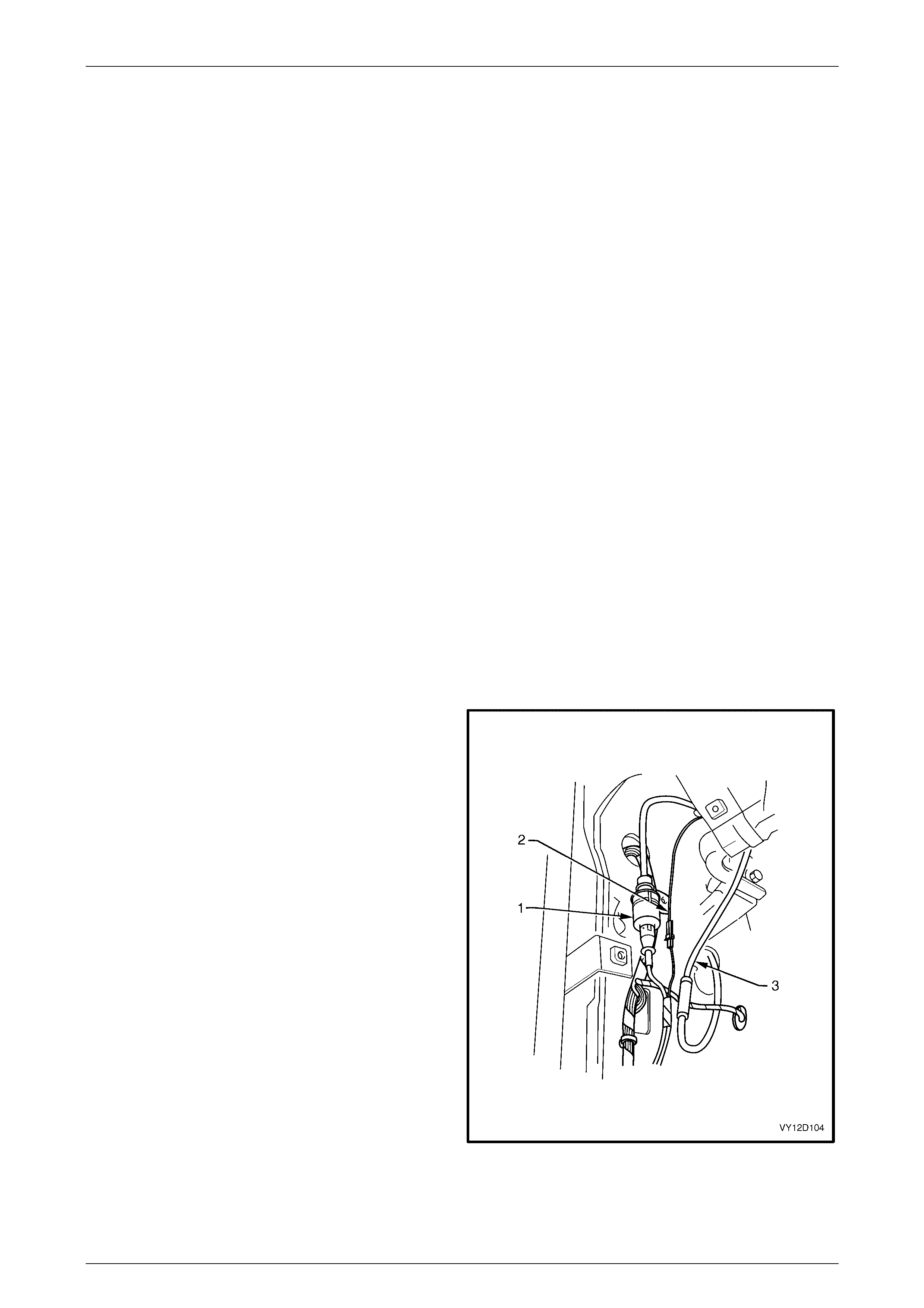
Entertainment System Page 12D–162
Page 12D–162
DTC 41 – No Class 2 Seri al Dat a
With the ignition in either the Accessories position or the On position, DTC 41 will set to indicate that the audio head unit
has not received any data from the Class II communications bus for more than 10 seconds. This does not necessarily
mean the audio head unit has a fault, the problem may lie with the MFD or bus wire preventing normal communications.
The DTC will clear when normal communications resume.
If DTC 41 is set, refer to Section 12I Multi Function Display in this Service Information for further diagnosis.
Diversity Antenna Fault Diagnosis
Before commencing the diagnostic procedure for the diversity antenna system the following should be checked:
Determine whether the reception problem is apparent with FM, AM or both. Faults affecting both FM and AM reception
are not caused by the diversity antenna system due to the fact that the diversity antenna system only affects FM
reception. The conventional fender mounted mast type antenna system is more likely to be cause of such faults.
Ensure that the customer complaint is not due to normal operation or the limitations of FM transmissions. The diversity
antenna system is designed to minimise distortion in the sound quality of FM reception and not to give large increases in
FM reception range.
Compare reception quality with that of another vehicle equipped with a diversity antenna system in the same location and
under the same conditions.
Diversity Antenna Syst em Test Procedure
NOTE
When the vehicle’s conventional antenna is
lowered, disconnected or faulty, the radio will not
use the diversity antenna system to receive FM
radio signals. If no FM stations can be received
then the fault is not due to the diversity antenna
system.
Refer to Radio Reception Diagnostic Chart in this Section before commencing to diagnose a diversity antenna related
system fault.
1 Remove the left-hand side still trim and plate
assembly. Refer to Section 1A8, 2.2 Side Sill Trim and
Plate in this Service Information.
2 Remove the left-hand side body lock pillar lower trim.
Refer to Section 1A8, 2.3 Body Lock Pillar Lower Trim
in this Service Information.
3 Remove the left-hand side hinge pillar trim assembly.
Refer to Section 1A8, 2.8 Hinge Pillar Trim Assembly
in this Service Information.
4 Leaving the wiring harnesses connected to the
exposed module, manoeuvre the module from the
plastic mounting bracket.
5 Remove the plastic mounting bracket.
Legend
1 Diversit y antenna coaxial cable
2 Diversit y antenna amplifier module power cable
3 Power antenna coaxial cable
6 Disconnect the diversity antenna amplifier module
power cable (2).
7 Test the voltage at the diversity antenna module-to-
main wiring harness connector with the key in
Accessories position. If 12 V is indicated, continue with
next step. If 0 V is indicated, trace wire back to fault
and repair.
Figure 12D – 133
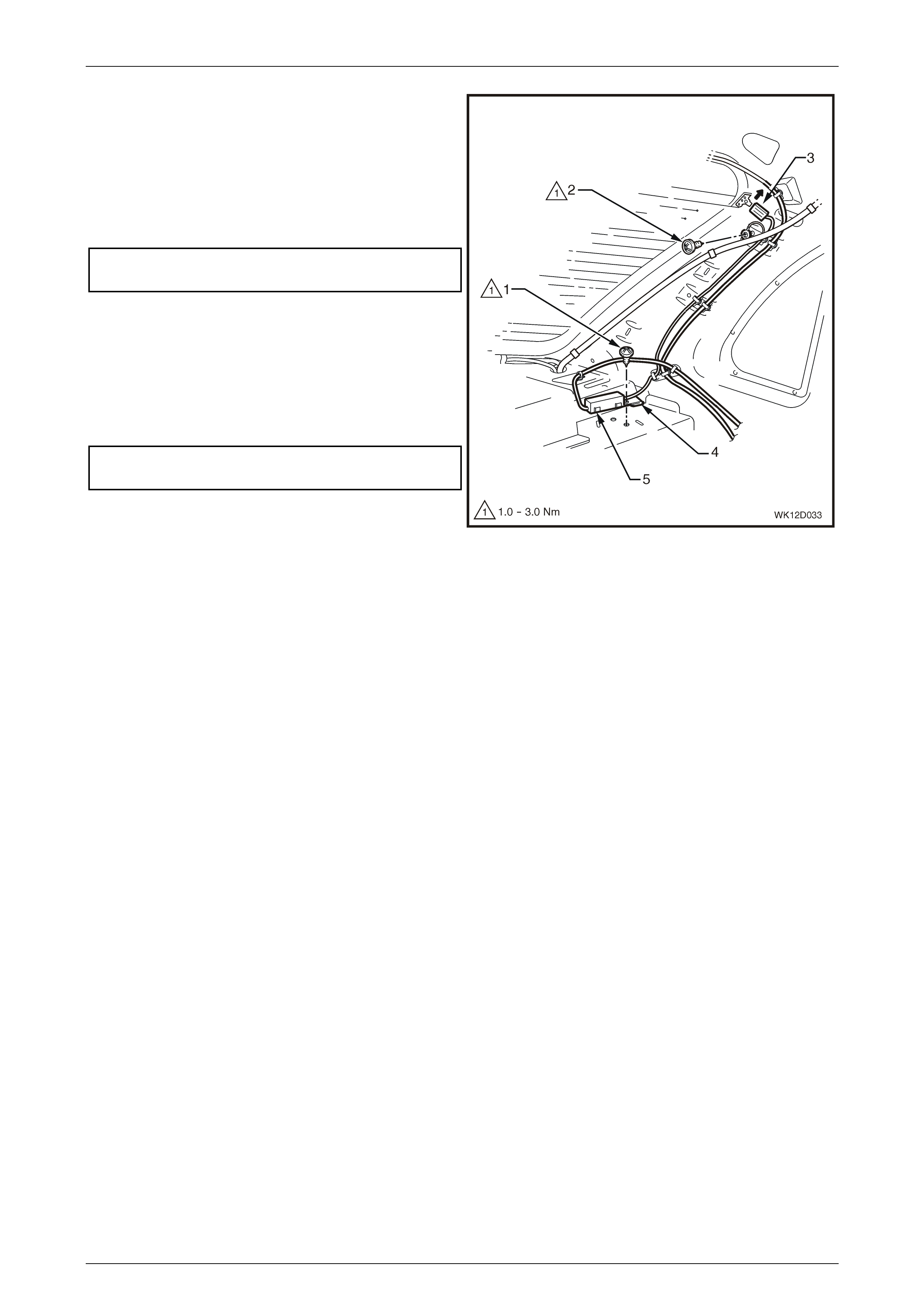
Entertainment System Page 12D–163
Page 12D–163
8 Remove the rear window trim panel assembly. Refer
to Section 1A8, 2.5 Rear Window Trim Panel
Assembly in this Service Information.
9 Check the connection from the diversity antenna
module connector (3) to the rear window connector.
Check the ground terminal (2) for a good electrical
ground. If necessary, tighten to the correct torque
specification.
Diversity antenna grounding
screw torque specification.......................... 1.0 – 3.0 Nm
10 Measure the resistance from the mounting tab (4) of
the diversity antenna amplifier module (5) to a good
ground point. If greater than 1 ohm, remove the
retaining screw (1) and module. Check that the mating
surfaces of the module and rear parcel shelf are clean
and free of any corrosion. Reinstall the module and
screw, tightening screw to the correct torque
specification and check the resistance again.
Diversity antenna module mounting
screw torque specification.......................... 1.0 – 3.0 Nm
Figure 12D – 134
11 Check the diversity antenna for continuity. Refer to 2.8 Diversity Antenna in this Section. If the antenna continuity is
acceptable then replace the diversity antenna amplifier module. Refer to 2.8 Diversity Antenna in this Section.

Entertainment System Page 12D–164
Page 12D–164
3.13 Diagnostic Trouble Codes – Premium
Sound Amplifier
Diagnostic Trouble Code History Data
When the Premium Sound Amplifier (PSA) detects an operating parameter which is outside its calibrated values it will set
a Diagnostic Trouble Code (DTC) and store this DTC into its memory as a current DTC.
When a DTC is set the PSA also stores the following history data for each DTC.
• DTC Status: Current or History
• DTC Number: The DTC number is the number used to identify a particular fault condition.
• Occurrence Count (0 to 255): The occurrence count is the number of times the particular fault condition has been
detected.
• History Count (0 to 255): The history count is the number of ignition cycles that have occurred since the fault was
last detected. A count of 0 indicates the fault has occurred on the current ignition cycle, while a count of 255
indicates that the fault occurred 255 or more ignition cycles ago.
When a DTC is first set, the occurrence count sets to 1 and the history count is set to 0. The history count determines the
age of a DTC. If the DTC already exists, then the occurrence count will be incremented (up to 255, at which point it is no
longer incremented), each time the DTC is set, the history count is cleared.
The occurrence and history counters provide a means of determining how often the fault has occurred, and how long it
has been since the fault last occurred. For instance, if the DTC occurrence count is 1, and the history count is 201, then it
can be determined that the fault condition existed only once, and it happened 201 ignition cycles ago (and has not been
detected since). Another example would be an occurrence count of 4 and a history count of 0. This would indicate that
the fault has been detected a total of four times, and that it was detected on the current ignition cycle.
Current and History DTCs and DTC history data can be read and cleared using TECH 2.
F0: Diagnostic Trouble Codes
1 From the Body Menu select F0: Diagnostic Trouble
Codes and press the Enter key (refer to Premium
Sound Amplifier Selection in this Section).
Figure 12D – 135
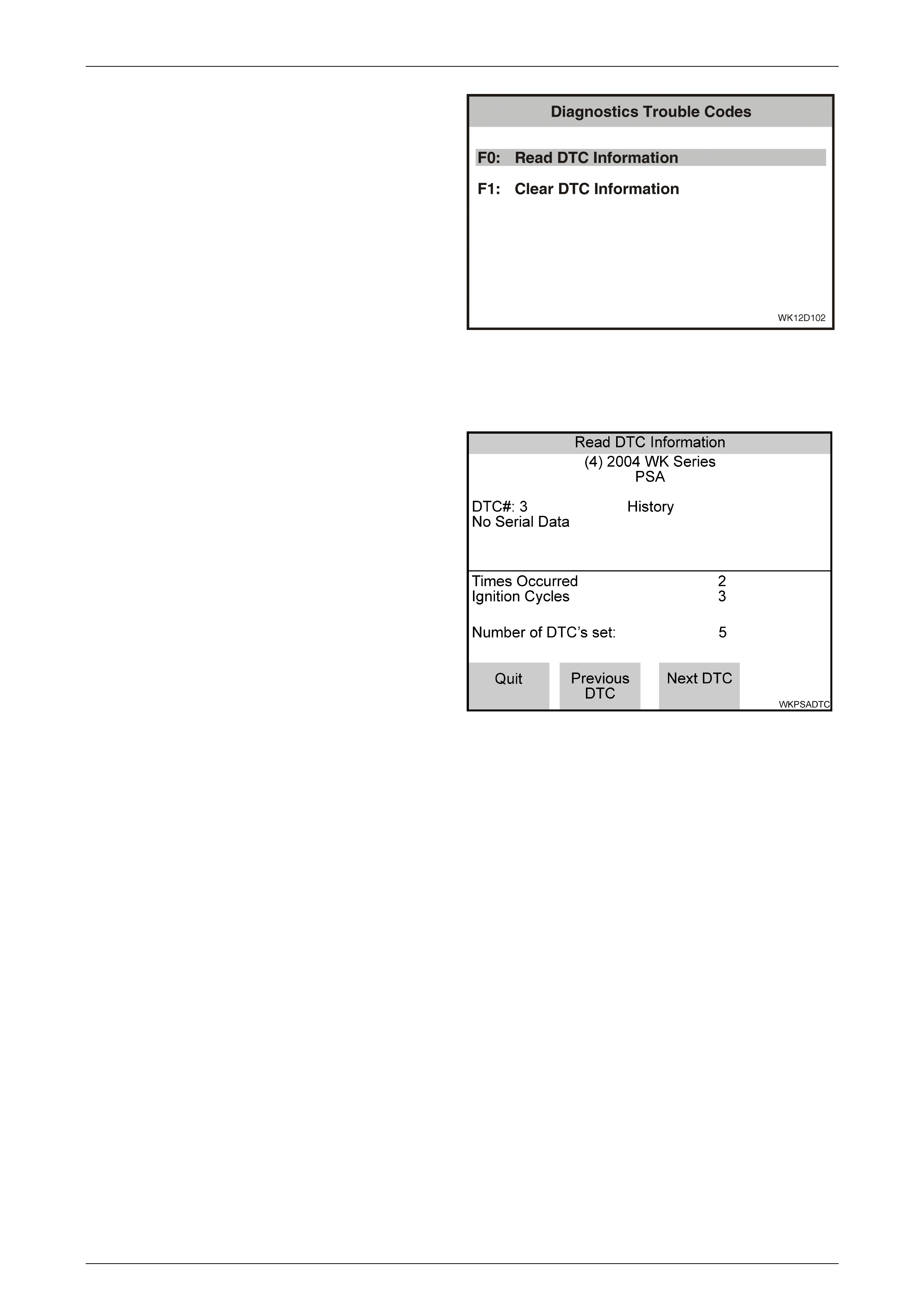
Entertainment System Page 12D–165
Page 12D–165
2 Using the TECH 2 Up and Down arrows, select the
required item and then press the Enter key.
F0: Read Current DTC Information. If this mode is
selected, a listing of all (if any) DTC that have been set by
the audio system will be displayed.
F1: Clear DTC Information. DTC can be cleared in this
mode by simply selecting F1: Clear DTC Information,
pressing the Enter key on TECH 2 and confirming the action
as instructed by TECH 2.
NOTE
TECH 2 will display Clear DTC Information, or
Failed if any DTC are still current.
Figure 12D – 136
Read DTC Informati on
When this mode is selected TECH 2 will display the
following DTC information:
• The DTC Number
• DTC Status either Current or History
• DTC Description
• Times Occurred
• Ignition Cycles since the DTC last set
• Number of DTCs set
If any DTCs are set, reference should be made to the
relevant diagnostic charts in this Section.
Figure 12D – 137
Premium Sound Amplifier Diagnostic Trouble Code List
The following DTC codes can be set by the premium sound amplifier:
• DTC 1 DSP Failure
• DTC 2 EEPROM Error
• DTC 3 No Serial Data
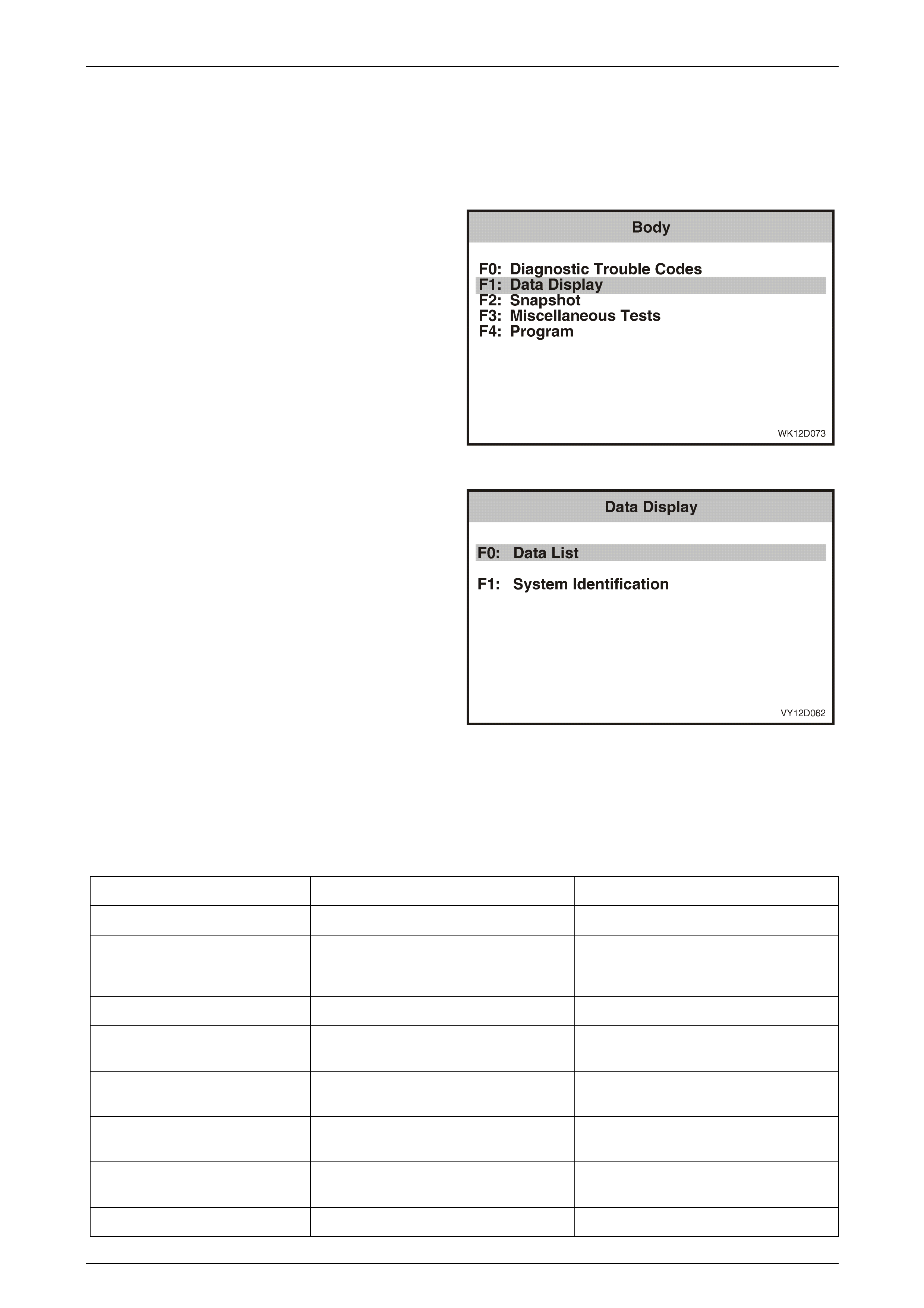
Entertainment System Page 12D–166
Page 12D–166
3.14 Diagnostic Data Display – Premium
Sound Amplifier
The Diagnostic Data Display function allows the status of the premium sound amplifier inputs and outputs to be
monitored, as well as the system identification details.
1 From the Body Menu select F1: Diagnostic Data
Display and press the Enter key (Refer to Premium
Sound Amplifier Selection in this Section).
Figure 12D – 138
2 Using the TECH 2 Up and Down arrows, select the
required item and then press the Enter key.
F0: Data List. If this mode is selected, a listing of all serial
data being sent and received by the premium sound
amplifier will be displayed.
F1: System Information. Provides details of system
identification.
Figure 12D – 139
F0: Data List
The serial data from the premium sound amplifier can be checked and tested by selecting the item and pressing the
Select Items soft key. The list can be scrolled by using the Up and Down arrow keys.
Data Display Data List
TECH 2 Displa y Range Remarks
PSA Status On / Off Display's On when the PSA is on.
Accessory Relay Active / Inactive Accessory relay status at connector
A15 6, te rminal X1-15. Display's Acti ve
when the ignition is on.
PSA DTC Status No DTC / DTCs Set Indicates whether there are DTCs set.
Front Speaker and Tweeter Gain 0 dB to +6 dB Display's the gain setting for the front
speakers and tweeters.
Rear and Roof Speaker Gain 0 dB to +6 dB Display's the gain setting for the rear and
roof speakers
Sub-Woofer Gain 0 dB to +6 dB Display's the gain setting for the
subwoofer spea ker s.
Vehicle Specific Equalizer On / Off Indicates whether the vehicle specific
equalizer is on or off.
Dynamic Distortion limiting On / Off Indicates whether the DDL is on or off.
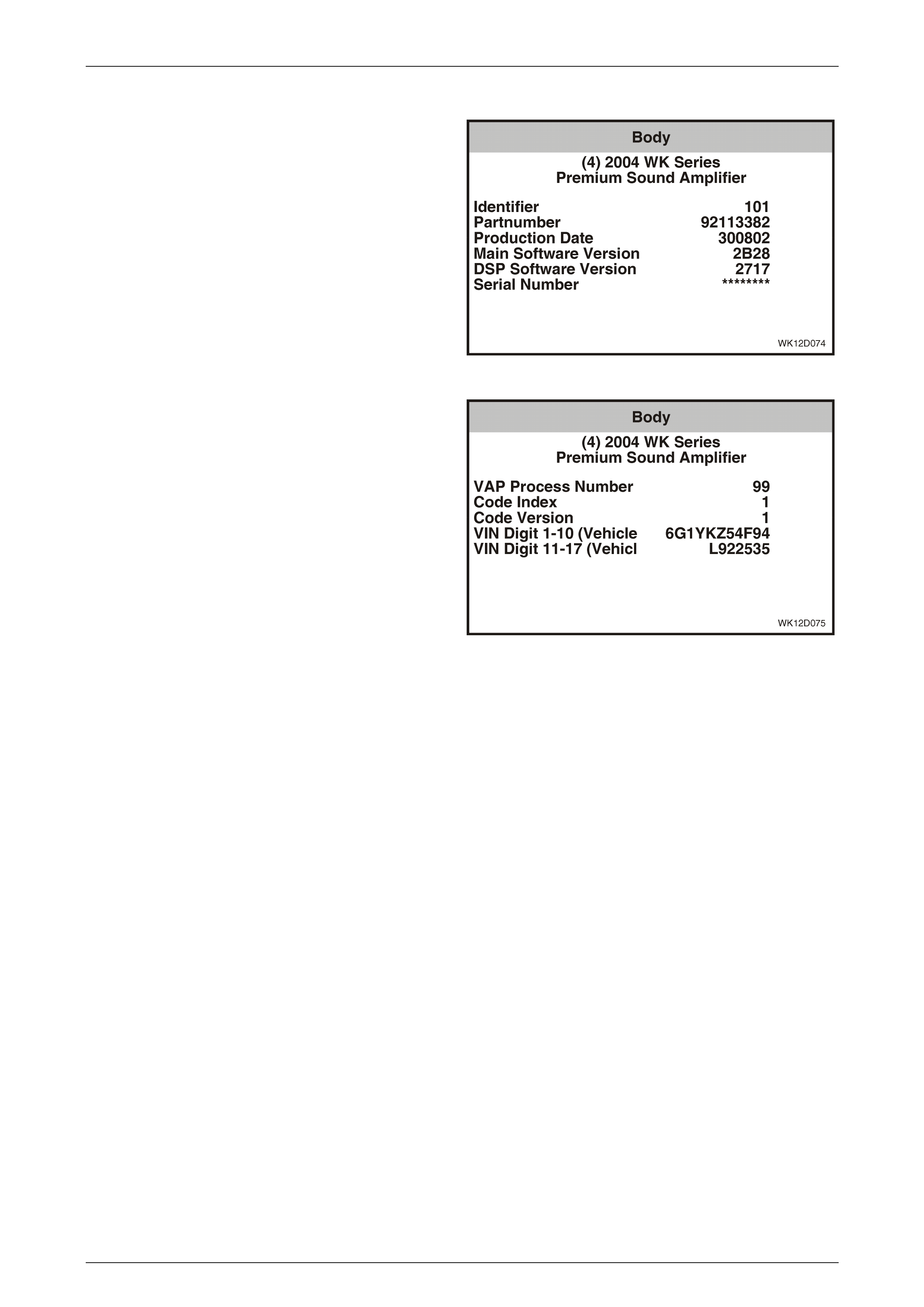
Entertainment System Page 12D–167
Page 12D–167
F1: System Identification
The System Identification screen provides production
information relevant to the premium sound amplifier.
Figure 12D – 140
Figure 12D – 141
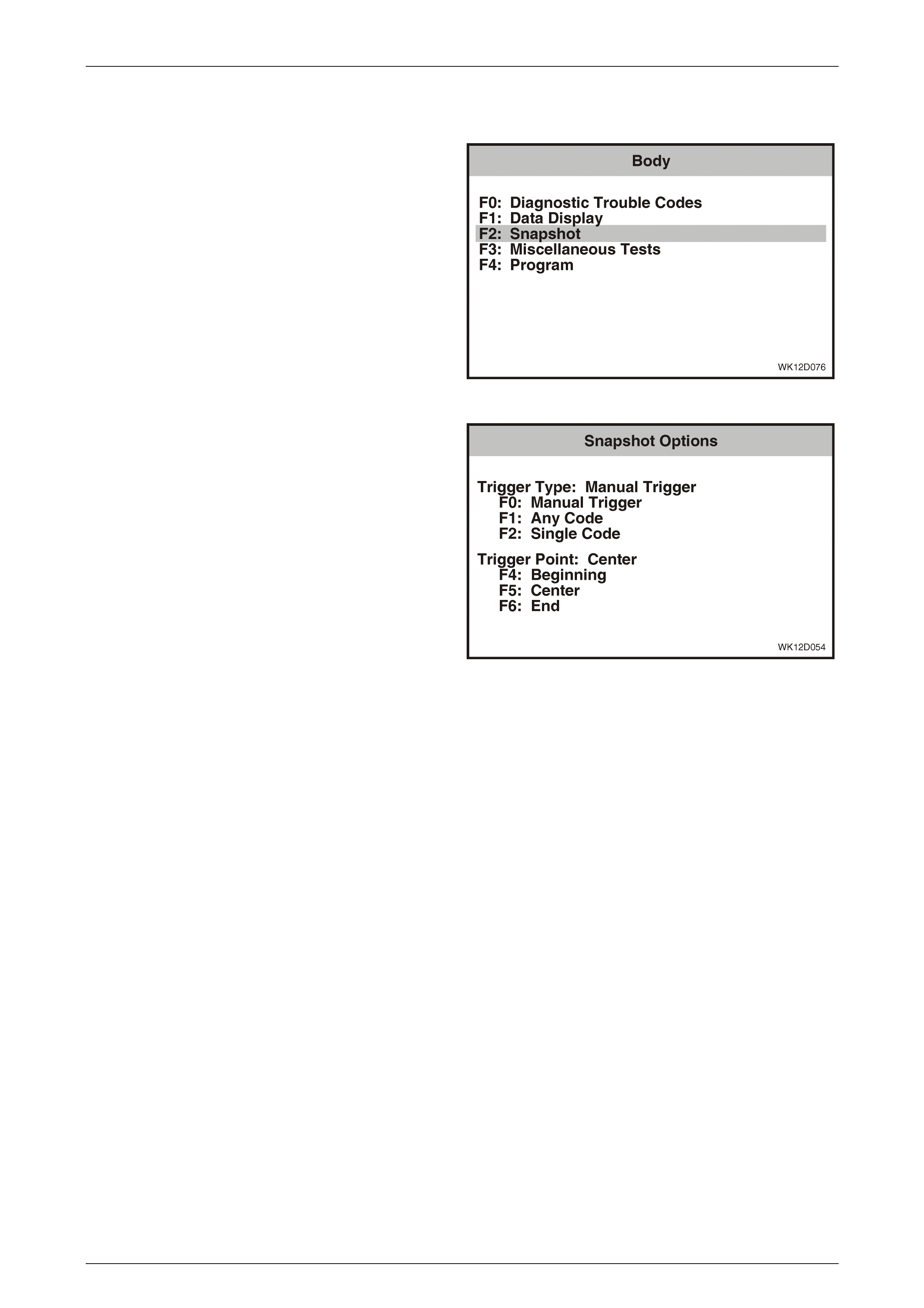
Entertainment System Page 12D–168
Page 12D–168
3.15 Snapshot – Premium Sound A mplifier
1 From the Body Menu select F2: Snapshot and press
the Enter key.
Figure 12D – 142
2 The TECH 2 can be used to record system information
that is occurring at a particular moment in time, and
this is called a snapshot. For more details, refer to
The TECH 2 User's Guide.
Figure 12D – 143
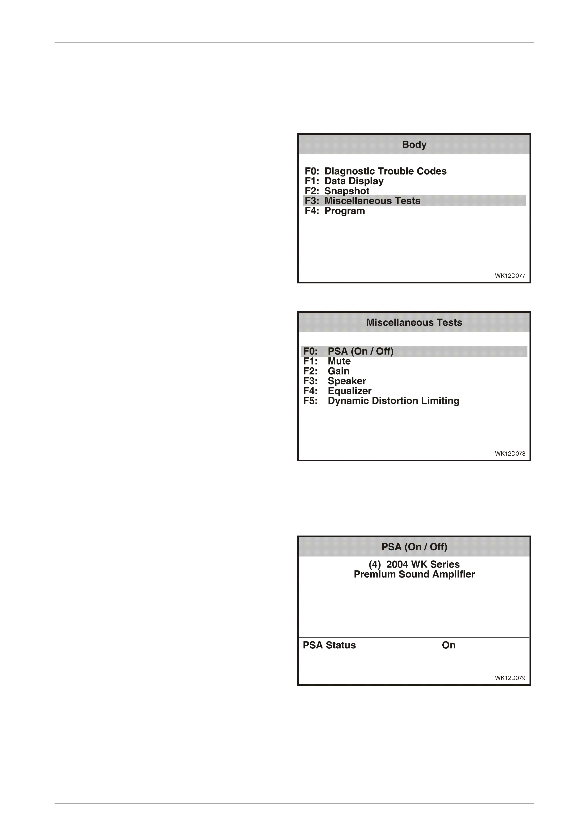
Entertainment System Page 12D–169
Page 12D–169
3.16 Miscellaneous Tests – Premium Sound
Amplifier
The TECH 2 can be used to verify correct operation of the various functions of the premium audio system to assist in
isolating a fault condition. The TECH 2 can be used to force various functions on or off and monitor the response.
1 From the Body Menu select F3: Miscellaneous Tests
and press the Enter key (Refer to Premium Sound
Amplifier Selection in this Section).
Figure 12D – 144
2 Using the TECH 2 Up and Down arrows, select the
required test and then press the Enter key.
Figure 12D – 145
F0: PSA (On / Off)
The PSA (On / Off) test is performed using TECH 2, and verifies that the PSA switches on and off correctly.
1 Connect TECH 2 to the DLC. Select Diagnostics /
Model Year / Vehicle Model / Body / Premium Sound
Amplifier / Miscellaneous Tests / PSA (On / Off).
2 Ensure that the ignition is on, and switch the audio
system on.
3 Select a radio station or play a CD so that there is
sound coming through the vehicle speakers.
4 The TECH 2 will display the current PSA status at the
bottom of the screen.
5 Press the On soft key on the TECH 2 and verify that
that sound is output from the speakers and that the
PSA On status is reflected on the TECH 2 screen.
6 Press the Off soft key on the TECH 2 and verify that
the sound from the speakers cuts out, and that the
PSA Off status is reflected on the TECH 2 screen.
7 Press the Quit soft key to exit the test.
8 If the PSA (On / Off) function does not operate
correctly, replace the premium sound amplifier. Refer
to 2.11 Premium Sound Amplifier in this Section.
Figure 12D – 146
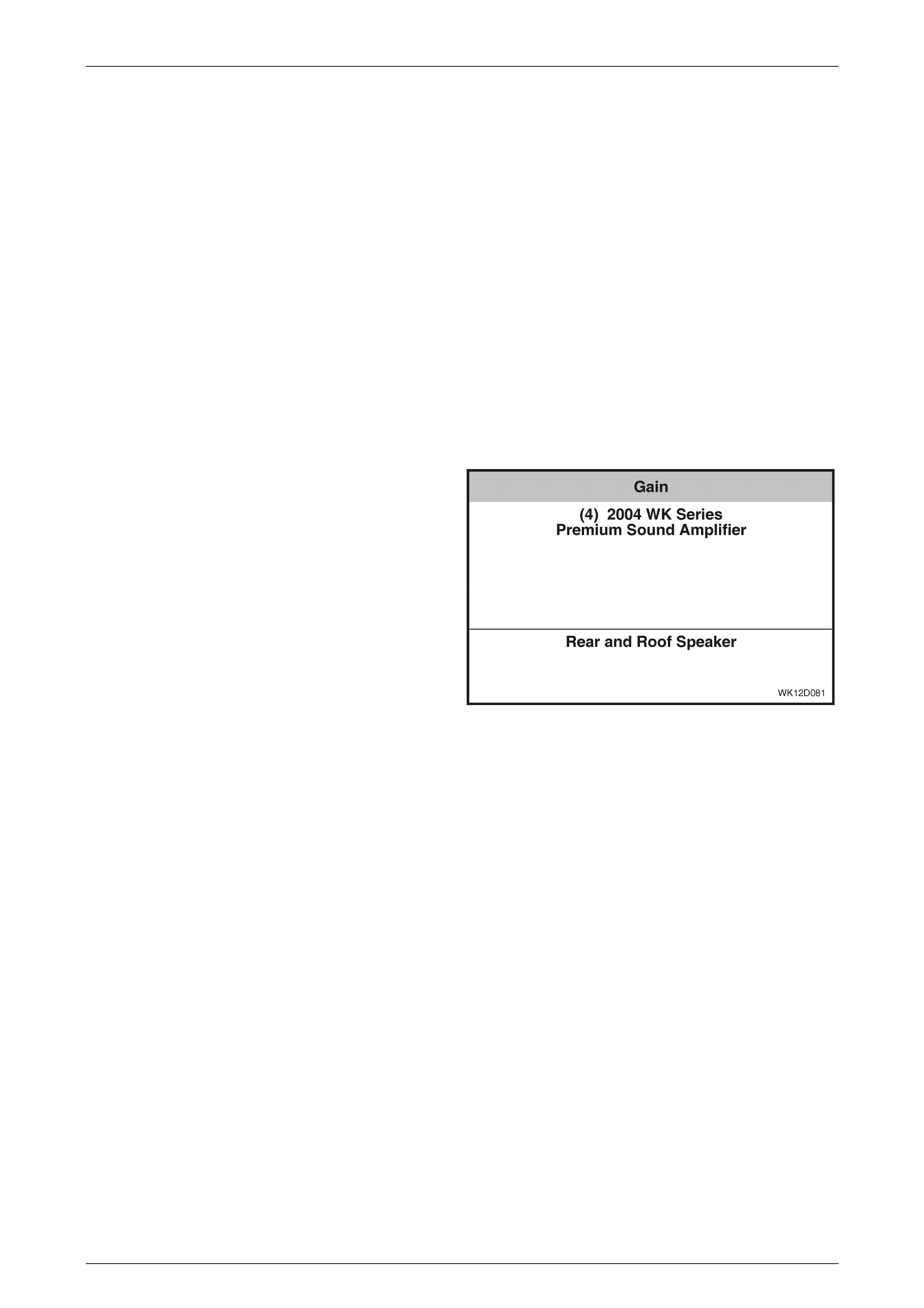
Entertainment System Page 12D–170
Page 12D–170
F1: Mute
The Mute test is performed using TECH 2, and verifies that the Mute function switches on and off correctly.
1 Connect TECH 2 to the DLC. Select Diagnostics / Model Year / Vehicle Model / Body / Premium Sound Amplifier /
Miscellaneous Tests / Mute.
2 Ensure that the ignition is on, and switch the audio system on.
3 Select a radio station or play a CD so that there is sound coming through the vehicle speakers.
4 Press the Unmute soft key on the TECH 2 and verify that the sound output from the speakers is at normal volume.
5 Press the Mute soft key on the TECH 2 and verify that the sound from the speakers is muted.
6 Press the Quit soft key to exit the test.
7 If the Mute function does not operate correctly, replace the premium sound amplifier. Refer to 2.11 Premium Sound
Amplifier in this Section.
F2: Gain
The Gain test is performed us ing TECH 2, and verifies that the Gain for the different speakers channels can be set
correctly. The rear and roof speakers, front speaker and tweeters and sub-woofer speaker channels can be selected.
1 Connect TECH 2 to the DLC. Select Diagnostics /
Model Year / Vehicle Model / Body / Premium Sound
Amplifier / Miscellaneous Tests / Gain.
2 Ensure that the ignition is on, and switch the audio
system on.
3 Select a radio station or play a CD so that there is
sound coming through the vehicle speakers.
4 The TECH 2 will display the current speaker channel
selection.
5 Press the Increase soft key on the TECH 2 and verify
that the gain from the displayed speaker channel
increases.
6 Press the Decrease soft key on the TECH 2 and verify
that the gain from the selected speaker channel
decreases.
7 Press the Next Channel soft key on the TECH 2 to
select the next speaker channel. Repeat steps 5 and 6
for all speaker channels.
8 Press the Quit soft key to exit the test.
9 If the Gain function does not operate correctly,
replace the premium sound amplifier. Refer to
2.11 Premium Sound Amplifier in this Section.
Figure 12D – 147
F3: Speaker
This miscellaneous test allows the active speaker channel to be changed by the user from the TECH 2. During this test
the PSA generates a test tone which is sent to the selected speaker channel, the test tone can be commanded on and
off using the On and Off soft keys.
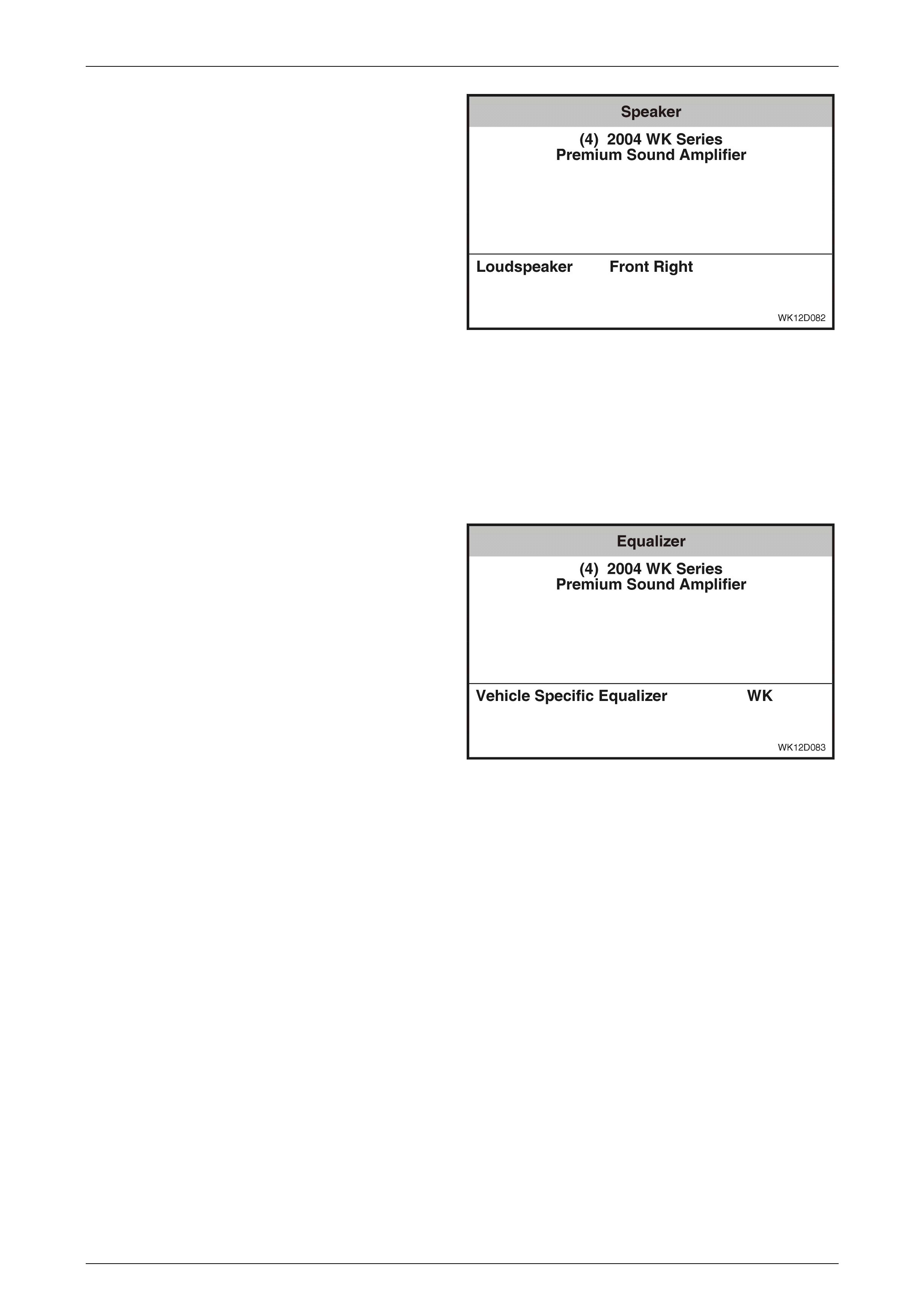
Entertainment System Page 12D–171
Page 12D–171
1 Connect TECH 2 to the DLC. Select Diagnostics /
Model Year / Vehicle Model / Body / Premium Sound
Amplifier / Miscellaneous Tests / Speaker.
2 Ensure that the ignition is on.
3 The TECH 2 will display the current speaker selection.
4 Press the On soft key on the TECH 2 and verify that
the test tone is heard from the selected speaker.
5 Press the Off soft key on the TECH 2 and verify that
the test tone from the selected speaker is turned off.
6 Press the Next Speaker soft key on the TECH 2 to
select the next speaker. Repeat Steps 4 and 5 for all
speakers.
8 Press the Quit soft key to exit the test.
9 If the Speaker function does not operate correctly,
replace the premium sound amplifier. Refer to
2.11 Premium Sound Amplifier in this Section.
Figure 12D – 148
F4: Equaliser
The equaliser test is performed using TECH 2, and verifies that the WK specific equaliser can be switched on and off.
1 Connect TECH 2 to the DLC. Select Diagnostics /
Model Year / Vehicle Model / Body / Premium Sound
Amplifier / Miscellaneous Tests / Equaliser.
2 Ensure that the ignition is on, and switch the audio
system on.
3 Select a radio station or play a CD so that there is
sound coming through the vehicle speakers.
4 The TECH 2 will display the current equaliser status at
the bottom of the screen.
5 Press the On soft key on the TECH 2 and verify that
that normal sound is output from the speakers and that
the correct WK Specific Equaliser status is reflected
on the TECH 2 screen.
6 Press the Off soft key on the TECH 2 and verify that
the sound from the speakers 'flattens', and that the
correct WK Specific Equaliser status is reflected on
the TECH 2 screen.
7 Press the Quit soft key to exit the test.
8 If the Equaliser function does not operate correctly,
replace the premium sound amplifier. Refer to
2.11 Premium Sound Amplifier in this Section.
Figure 12D – 149

Entertainment System Page 12D–172
Page 12D–172
F5: Dynamic Distortion Limiting
The Dynamic Distortion Limiting (DDL) test is performed using TECH 2, and verifies that the DDL can be switched on
and off.
1 Connect TECH 2 to the DLC. Select Diagnostics /
Model Year / Vehicle Model / Body / Premium Sound
Amplifier / Miscellaneous Tests / Dynamic Distortion
Limiting.
2 Ensure that the ignition is on, and switch the audio
system on.
3 The TECH 2 will display the current DDL status at the
bottom of the screen.
5 Press the On soft key on the TECH 2 and verify that
that the DDL is turned on.
6 Press the Off soft key on the TECH 2 and verify that
the DDL is turned off.
7 Press the Quit soft key to exit the test.
8 If the DDL function does not o perate correctly,
replace the premium sound amplifier. Refer to
2.11 Premium Sound Amplifier in this Section.
Figure 12D – 150
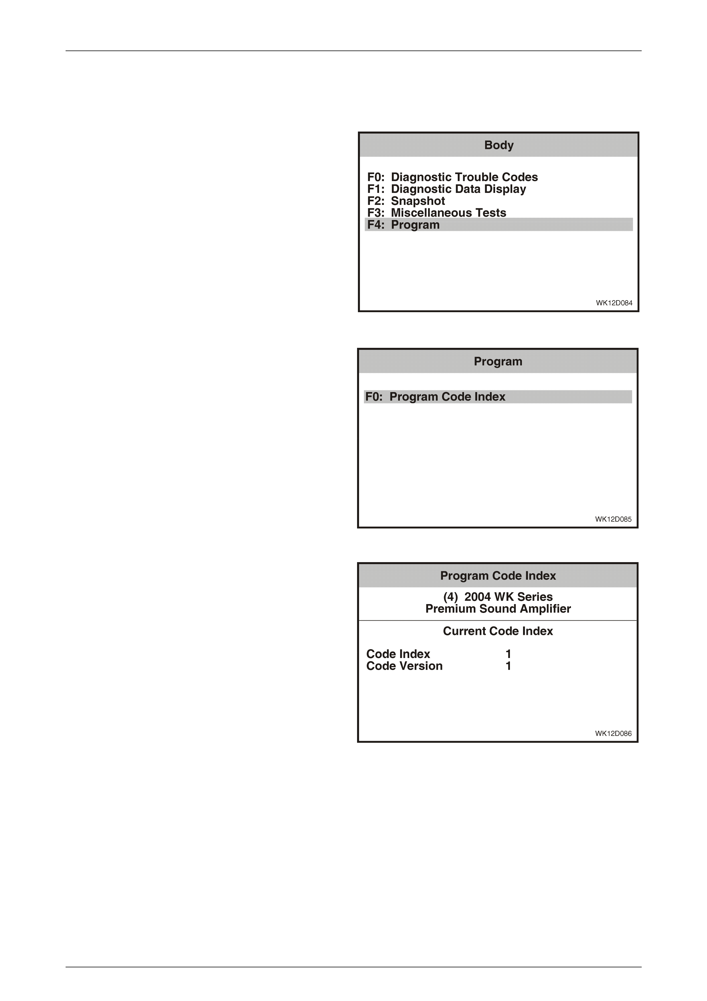
Entertainment System Page 12D–173
Page 12D–173
3.17 Program – Premium Sound Amplifier
The Program function allows the programming of the premium sound amplifier code index.
1 From the Body Menu select F4: Program and press
the Enter key.
Figure 12D – 151
2 From the Program Menu select F0: Program Code
Index and press the Enter key.
Figure 12D – 152
2 The Code Index number and the Code Version
number are displayed. To change the Code Index
number, press the Program soft key. To exit without
making a change, press the Okay soft key.
Figure 12D – 153

Entertainment System Page 12D–174
Page 12D–174
3 Enter Code Index number using the numeral keys on
TECH 2.
4 Press the Enter key to continue, or the Exit key to exit
without making a change.
5 Follow any TECH 2 screen prompts when
programming is co mple ted.
Figure 12D – 154
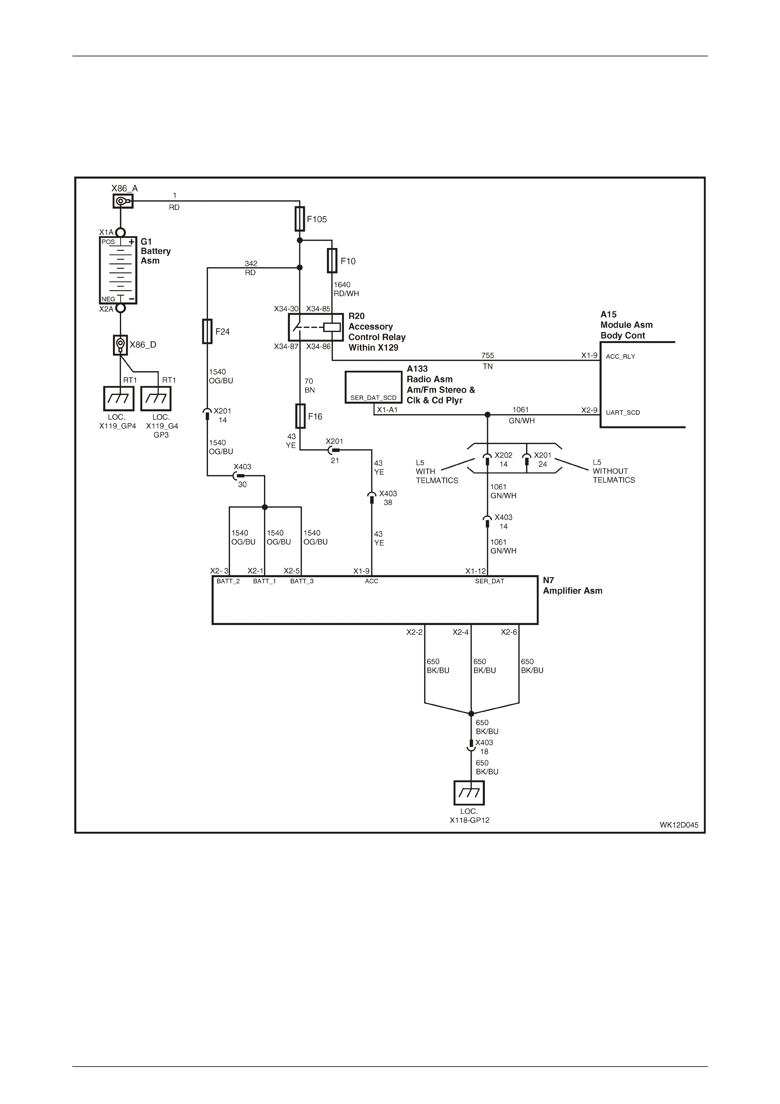
Entertainment System Page 12D–175
Page 12D–175
3.18 Premium Sound Amplifier Diagnostic
Procedures
PSA Diagnostic Circuit Check
Figure 12D – 155
The PSA delivers high power to all of the upgraded vehicle speakers. The four channel sound output from the audio
head unit is taken to the amplifier where it passes through a DSP system before being amplified and sent to the vehicle
speakers. The amplifier is internally protected by two fuses against short circuits and connection to voltage sources on
the speaker wires.
The PSA is connected to the main vehicle communications bus, and therefore has its own TECH 2 diagnostic capability.
The serial data communications between the PSA and the BCM and audio system is via circuit 1061 to terminal X1-12.
The high power requirements of the PSA mean the power supply and earth circuits are very important to ensure smooth
operation. Carefully inspect each connection to make sure they are tight and free from corrosion. The PSA is supplied
with power from the main battery via circuit 1540 to terminals X2-1, X2-3 and X2-5 and from the accessory control relay
via circuit 43 to terminal X1-9 . Connection to vehicle ground is made on terminals X2-2, X2-4 and X2-6, via circuit 650.

Entertainment System Page 12D–176
Page 12D–176
PSA Diagnostic Circuit Check Diagnostic Chart
Step Action Value(s) Yes No
1 Has the audio system diagnostic circuit check been
performed? Go to Step 2. Perform the audio
system diagnostic
circuit che ck.
Refer to
Audio System
Diagnostic Circuit
Check
in this Section.
2 Turn the radio on and set the volume to a medium level.
NOTE
If radio reception is poor, place a CD into the
CD player and press play.
Is sound audible from the speakers?
Go to Step 3. Go to
PSA No Sound
Diagnostic Chart
in this Section.
3 Is the sound heard through the speakers clear and
undistorted? Go to Step 4. Refer to
No Sound Or
Distorted Sound –
Level 5 Vehicles
in this Section for
further diagnosis .
4 Turn the ignition On.
Connect TECH 2 to the DLC.
Select Diagnostics / Model Year / Vehicle Model / Body
/ Premium Sound Amplifier / Diagnostic Trouble Codes /
Read Diagnostic Trouble Codes.
Are any current DTCs set?
Go to the relevant
DTC diagnostic
chart in this Section.
System OK.
WHEN ALL DIAGNOSIS AND REPAIRS ARE COMPLETED, VERIFY CORRECT OPERATION
PSA No Sound
This diagnostic chart is used to determine the cause for an absence of sound from the audio system speakers. The loss
of all sound can be caused by a loss of serial communications between the PSA and the audio system, a non compatible
AHU, or a fault in the PSA.
PSA No Sound Diagnostic Chart
Step Action Value(s) Yes No
1 Has the PSA diagnostic circuit check been performed? Go to Step 2. Perform the PSA
diagnost ic cir cui t
check. Refer to
PSA Diagnostic
Circuit Check
in this Section.
2 Turn the ignition On.
Connect TECH 2 to the DLC.
Select Diagnostics / Model Year / Vehicle Model / Body
/ Premium Sound Amplifier..
Does TECH 2 display PSA identification data?
Go to Step 3. Refer to
DTC 3 – No
Serial Data
in this Section for
further diagnosis .

Entertainment System Page 12D–177
Page 12D–177
Step Action Value(s) Yes No
3 On TECH 2 select Audio System / Data Display /
System Identification.
Find the audio system identifier number. Refer to
3.8 Diagnostic Data Display – Audio System, F1:
System Identifier in this Section for identifier number
details.
Is the identifier number the values specified?
601 Go to Step 4. Remove AHU and
replace with a Level
5 WK series AHU.
4 On TECH 2, select Premium Sound Amplifier /
Diagnostic Trouble Codes / Read Diagnostic Trouble
Codes.
Are any current DTCs set?
Go to the relevant
DTC diagnostic
chart in this Section.
Go to Step 5.
5 Check connectors X403 and X200 (and X202 if vehicle
fitted with Telematics)..
Are connectors X403 and X200 (and 202) OK?
Replace PSA.
Refer to
2.11 Premium
Sound Amplifier
in this Section.
Repair faulty
connector or
terminal.
WHEN ALL DIAGNOSIS AND REPAIRS ARE COMPLETED, VERIFY CORRECT OPERATION
PSA No Power
The PSA is supplied with power from the main battery via circuit 1540 to terminals X2-1, X2-3 and X2-5 and from the
accessory control relay via circuit 43 to terminal X1-9. Connection to vehicle ground is made on terminals X1-10, X2-2,
X2-4 and X2-6, via circuit 650.
PSA No Power Diagnostic Chart
Step Action Value(s) Yes No
1 Has the PSA diagnostic circuit check been performed? Go to Step 2. Perform the PSA
diagnost ic cir cui t
check. Refer to
PSA Diagnostic
Circuit Check
in this Section.
2 Check the two PSA fuses (refer to 2.11 Premium Sound
Amplifier in this Section).
Are the fuses OK?
Go to Step 3. Replace fuses.
3 Remove PSA connector N7-X1.
Turn the ignition to the accessories position.
Using a digital voltmeter, measure the voltage between
PSA connector N7, terminal X1-9, circuit 43 and a
known good ground.
Is the voltage as specified?
12.5V. Go to Step 5. Go to Step 4.
4 Check fuse F16 and circuits 43 and 70.
Are fuse F16 and circuits 43 and 70 OK?
Refer to
Section 12J,
4.4 Accessory
Power Control
in the MY 2003 VY
and V2 Series
Service Information
for further diagnosis.
Replace fuse F16 or
repair faulty
circuit 43 or 70.

Entertainment System Page 12D–178
Page 12D–178
Step Action Value(s) Yes No
5 Remove connector N7-X2.
Using a digital voltmeter, measure the voltage between
the following terminals and a known good ground:
• Connector N7–X2, terminal X2-3,circuit 1540
• Connector N7–X2, terminal X2-1,circuit 1540
• Connector N7–X2, terminal X2-5,circuit 1540
Is the voltage as specified?
12.5 V. Go to Step 7. Go to Step 6.
6 Check circuit 1540 and fuse F24.
Is circuit 1540 and fuse F24 OK?
No battery power to
circuit 1540 or Fuse
F24. C heck circuit 1
and 342 to Fuse
F24. Repair fault in
circuit.
Repair faulty
circuit 1540 or
replace fuse F24.
7 Using a digital ohmmeter, measure the resistance
between the following terminals and a known good
ground:
• Connector N7–X2, terminal X2-2, circuit 650
• Connector N7–X2, terminal X2-4, circuit 650
• Connector N7–X2, terminal X2-6, circuit 650
Is the value as specified?
Continuity Reinstall connector
N7–X2.
Refer to
DTC 3 – No
Serial Data
in this Section for
further diagnosis .
Repair faulty
circuit 650.
WHEN ALL DIAGNOSIS AND REPAIRS ARE COMPLETED, VERIFY CORRECT OPERATION
DTC 1 – DSP Failure
With the ignition in either the Accessories position or the On position, DTC 1 will set to indicate a failure in the DSP
module of the PSA.
If DTC 1 is set, replace the PSA. Refer to 2.11 Premium Sound Amplifier in this Section.
DTC 2 – EEPROM Failure
With the ignition in either the Accessories position or the On position, DTC 2 will set to indicate that the PSA is unable to
read and / or write to EEPROM.
If DTC 2 is set, replace the PSA. Refer to 2.11 Premium Sound Amplifier in this Section.

Entertainment System Page 12D–179
Page 12D–179
DTC 3 – No Serial Data
With the ignition in either the Accessories position or the On position, DTC 3 will set to indicate that the PSA has not
received any data from the audio system for more than 10 seconds.
DTC 3 – No Serial Data Diagnostic Chart
Step Action Value(s) Yes No
1 Has the PSA diagnostic circuit check been performed? Go to Step 2. Perform PSA
diagnost ic cir cui t
check.
2 Turn ignition off.
Remove PSA connector N7-X1.
Turn ignition on.
Using a digital voltmeter, measure the voltage between
PSA connector N7, terminal X1-12, circuit 1061 and a
known good ground.
Is the voltage as specified?
3 to 4 V. Refer to
PSA No Power
Diagnostic Chart
in this Section for
further diagnosis .
Go to Step 3.
3 Using a digital ohmmeter, measure the resistance
between PSA connector N7, terminal X1-12, circuit
1061 and a known good groun d.
Is the value as specified?
Open circuit. Repair short to
ground in circuit
1061.
Replace Radio.
Refer to
2.1 Audio System
Head Unit
in this Section.
WHEN ALL DIAGNOSIS AND REPAIRS ARE COMPLETED, VERIFY CORRECT OPERATION
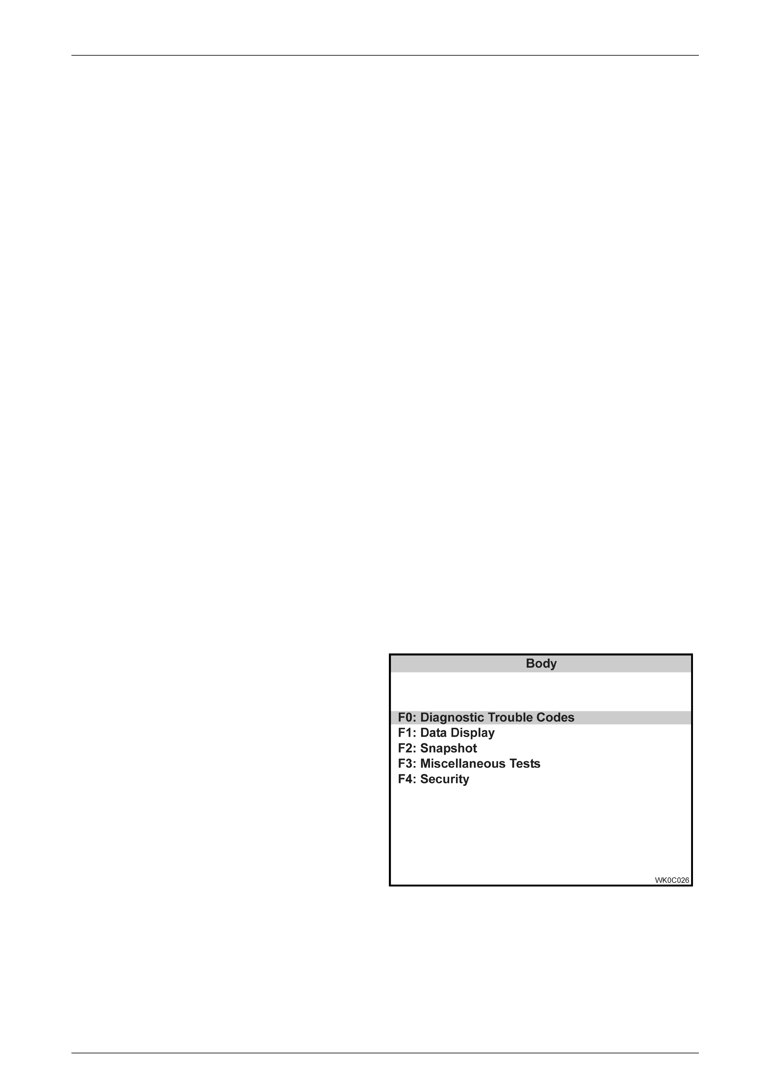
Entertainment System Page 12D–180
Page 12D–180
3.19 Diagnostic Trouble Codes – Audio
Interface Module
Diagnostic Trouble Code History Data
When the Audio Interface Module (AIM) detects an operating parameter which is outside its calibrated values it will set a
Diagnostic Trouble Code (DTC) and store this DTC into its memory as a current DTC.
When a DTC is set the AIM also stores the following history data for each DTC:
• DTC Status: Current or History
• DTC Number: The DTC number is the number used to identify a particular fault condition.
• Occurrence Count (0 to 255): The occurrence count is the number of times the particular fault condition has been
detected.
• History Count (0 to 255): The history count is the number of ignition cycles that have occurred since the fault was
last detected. A count of 0 indicates the fault has occurred on the current ignition cycle, while a count of 255
indicates that the fault occurred 255 or more ignition cycles ago.
The AIM is capable of storing history data for up to ten DTCs. Therefore, if more than ten DTCs are set, only history data
for the last ten will be tracked. That is, the history data for the oldest DTC will be removed from the AIM. Once a DTC
history data has been removed, it is maintained in the memory of the AIM as a History DTC, however there will be no
DTC history data available for this DTC.
When a DTC is first set the occurrence count is set to 1 and the history count is set to 0. The history count determines
the age of a DTC. If there are more that ten DTCs, the DTC with the highest history count will be removed to make space
for the new DTC. If the DTC already exists, then the occurrence count will be incremented (up to 255, at which point it is
no longer incremented). Each time the DTC is set, the history count is cleared and this ensures that the ten most recent
DTCs are tracked.
The occurrence and history counters provide a means of determining how often the fault has occurred, and how long it
has been since the fault last occurred. For instance, if the DTC occurrence count is 1, and the history count is 201, then it
can be determined that the fault condition existed only once, and it happened 201 ignition cycles ago (and has not been
detected since). Another example would be an occurrence count of 4 and a history count of 0. This would indicate that
the fault has been detected a total of four times, and that it was detected on the current ignition cycle.
Current and History DTCs and DTC history data can be read and cleared using TECH 2.
F0: Diagnostic Trouble Codes
1 From the Body Menu select F0: Diagnostic
Trouble Codes and press the Enter key (refer to
Audio Interface Module Selection in this Section).
Figure 12D – 156
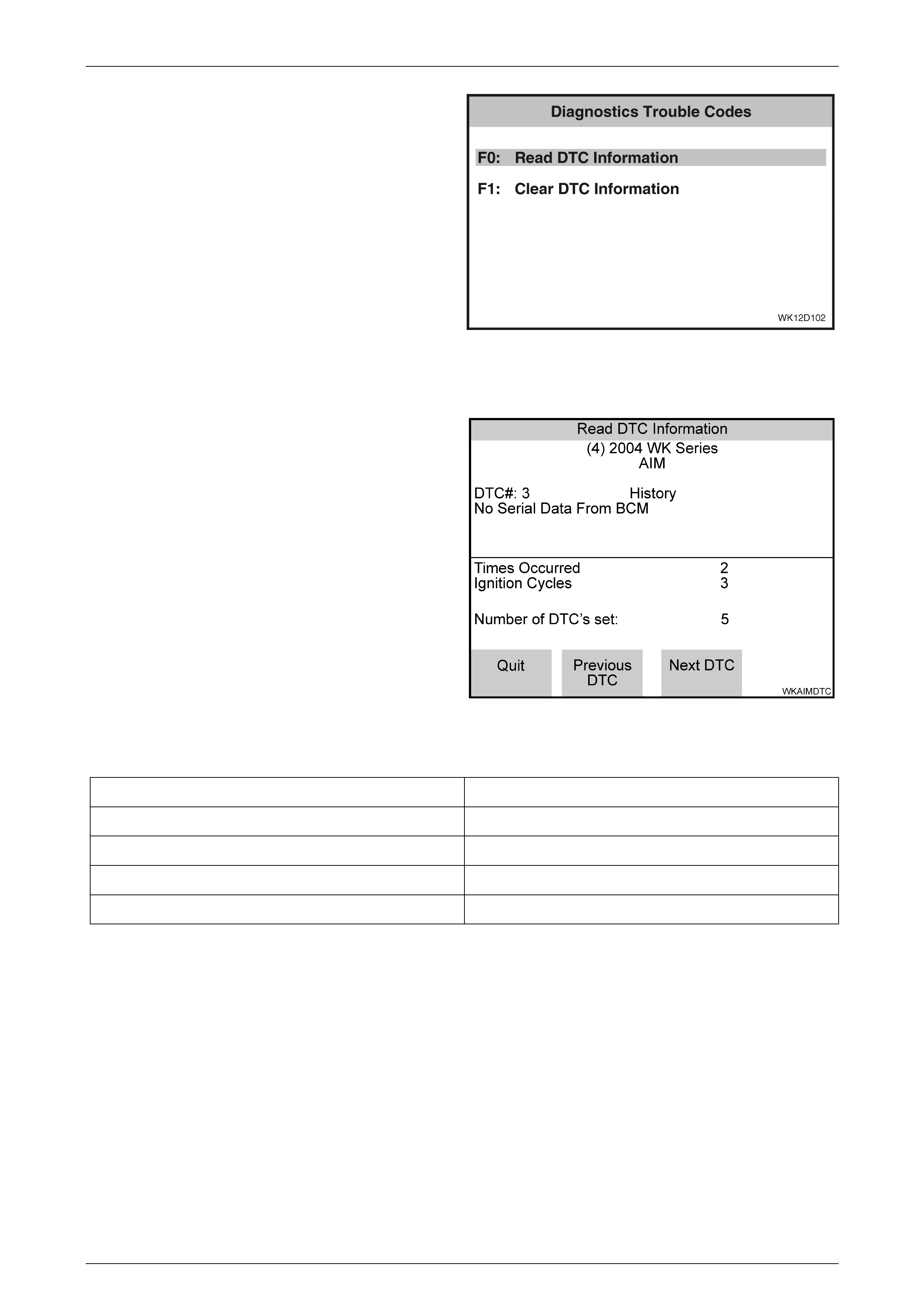
Entertainment System Page 12D–181
Page 12D–181
2 Using the TECH 2 Up and Down arrows, select the
required item and then press the Enter key.
F0: Read Current DTC Information. If this mode is
selected, a listing of all (if any) DTC that have been set by
the audio interface module will be displayed.
F1: Clear DTC Information. DTC can be cleared in this
mode by simply selecting F1: Clear DTC Information,
pressing the Enter key on TECH 2 and confirming the action
as instructed by TECH 2.
NOTE
TECH 2 will display Clear DTC Information
Failed if any DTCs are still current.
Figure 12D – 157
Read Current DTC Inf orma tion
When this mode is selected TECH 2 will display the
following DTC information:
• The DTC Number
• DTC Status either Current or History
• DTC Description
• Times Occurred
• Ignition Cycles since the DTC last set
• Number of DTCs set
If any DTCs are set, reference should be made to the
relevant diagnostic charts in this Section.
Figure 12D – 158
Audio Interface Module Diagnostic Trouble Code List
DTC 1 No Class 2 Serial Da ta from DVD DTC 7 No Class 2 Serial Da ta
DTC 2 DVD Not Initialise d DTC 8 Wrong Security Code (System Locke d)
DTC 3 No Serial Data From BCM DTC 11 Class 2 Hardware Failure
DTC 4 No Serial Data From Audio System DTC 12 EEPRO M Mirror Checksum Error
DTC 5 Loss of Accessory Power Supply DTC 13 EEPROM Checksum Error
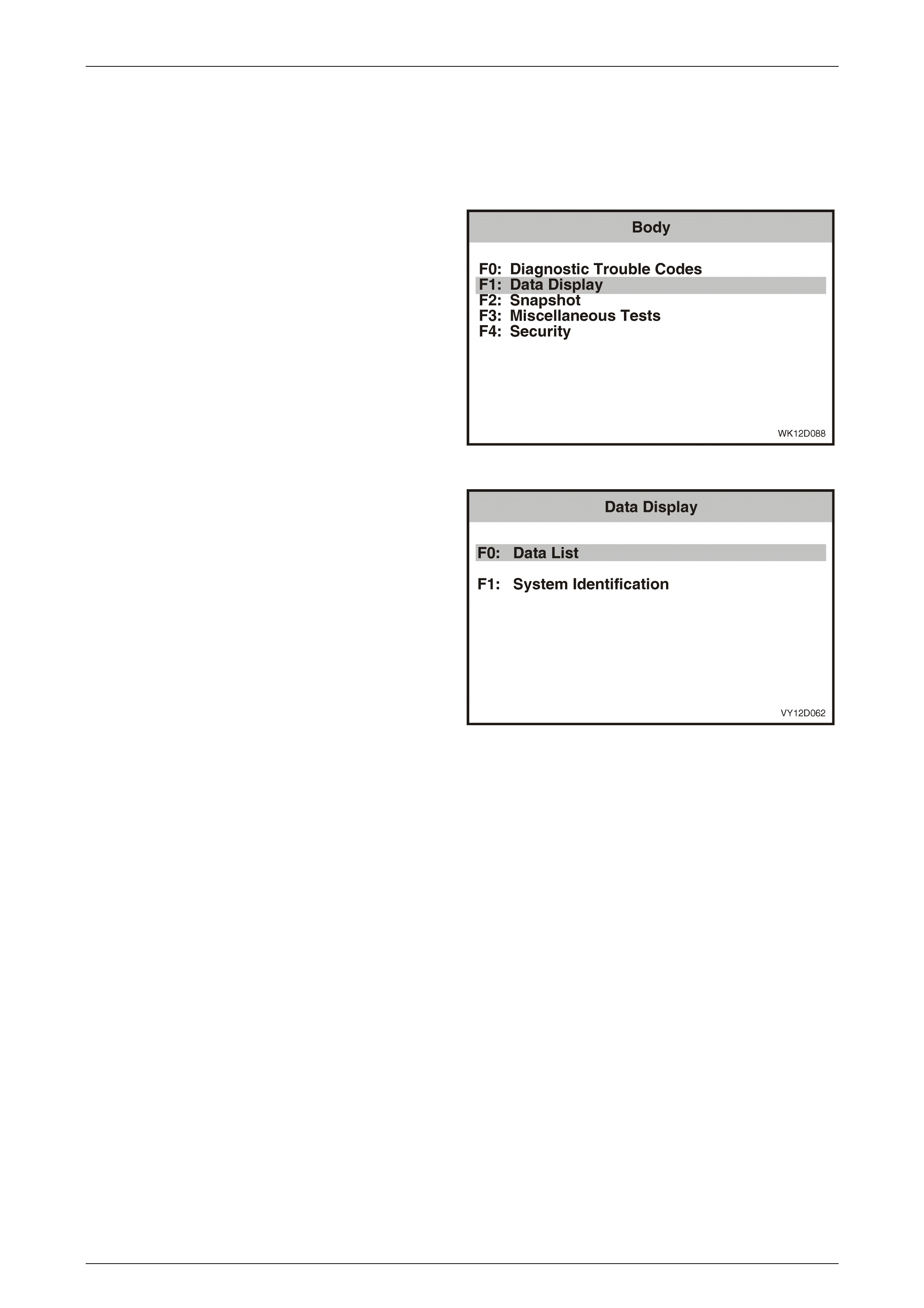
Entertainment System Page 12D–182
Page 12D–182
3.20 Diagnostic Data Display – Audio
Interface Module
The Diagnostic Data Display function allows the status of the audio system inputs and outputs to be monitored, as well
as the system identification details.
1 From the Body Menu select F1: Diagnostic Data
Display and press the Enter key.
Figure 12D – 159
2 Using the TECH 2 Up and Down arrows, select the
required item and then press the Enter key.
F0: Data List. If this mode is selected, a listing of all serial
data being sent by the audio interface module will be
displayed.
F1: System Information. Provides details of system
identification.
Figure 12D – 160
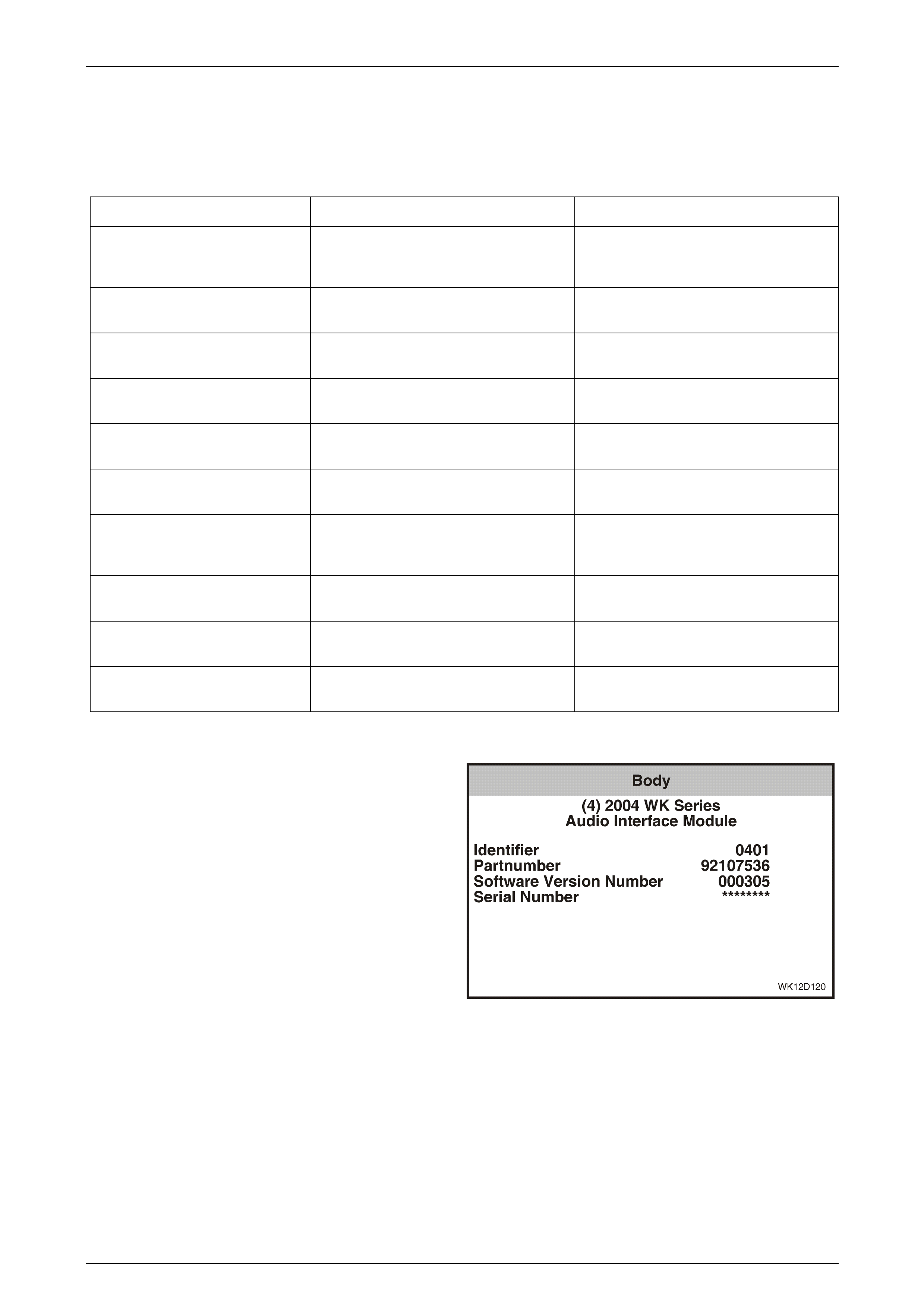
Entertainment System Page 12D–183
Page 12D–183
F0: Data List
The serial data from the audio interface module can be checked and tested by selecting the item and pressing the Select
Items soft key. The list can be scrolled by using the Up and Down arrow keys.
Data Display Data List
TECH 2 Displa y Range Remarks
AIM Status On / Off Indicates whether the AIM is on or off.
The aim is powered through the
Accessory Relay.
DVD Status On / Off Indicates whether the DVD player is on or
off.
AIM Linked to BCM Yes / No Indicates whether the AIM is linked to the
BCM or not.
DVD Class 2 Communication Present / Not Present Indicates the status of AIM
communication with the DVD player.
DVD Requested Yes / No Indicates whether the DVD player mode
is selected in the AHU.
DVD Connected Yes / No Indicates whether the DVD player is
connected.
AIM Request DVD Parental
Lockout Yes / No Indicates whether the parental lockout
signal is being sent to the AIM from the
AHU.
DVD Parental Lockout Status On / Off Indicates the current status of the
parental lockout feature.
DVD Illumination On / Off Indicates whether the DVD illumination is
on or off.
DVD Illumination Level % 0-100% Indicates the intensity of the DVD
illumination when the park lamps are On.
F1: System Identification
The System Identification screen provides production
information relevant to the Audio Interface Module.
Figure 12D – 161
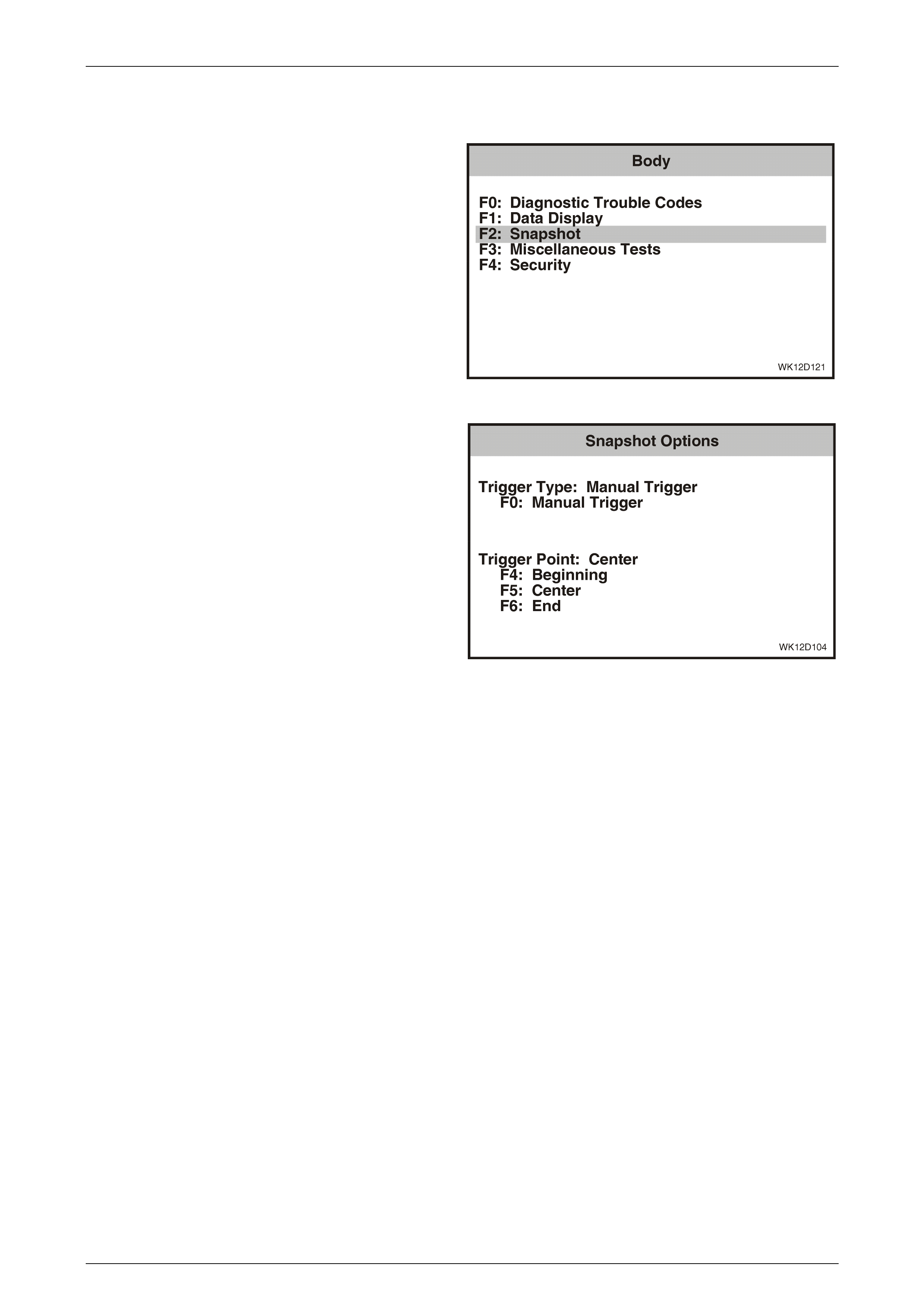
Entertainment System Page 12D–184
Page 12D–184
3.21 Snapshot – Audio Interface Module
1 From the Body Menu select F2: Snapshot and press
the Enter key.
Figure 12D – 162
2 The TECH 2 can be used to record system information
that is occurring at a particular moment in time, and
this is called a snapshot. For more details, refer to
The TECH 2 User's Guide.
Figure 12D – 163
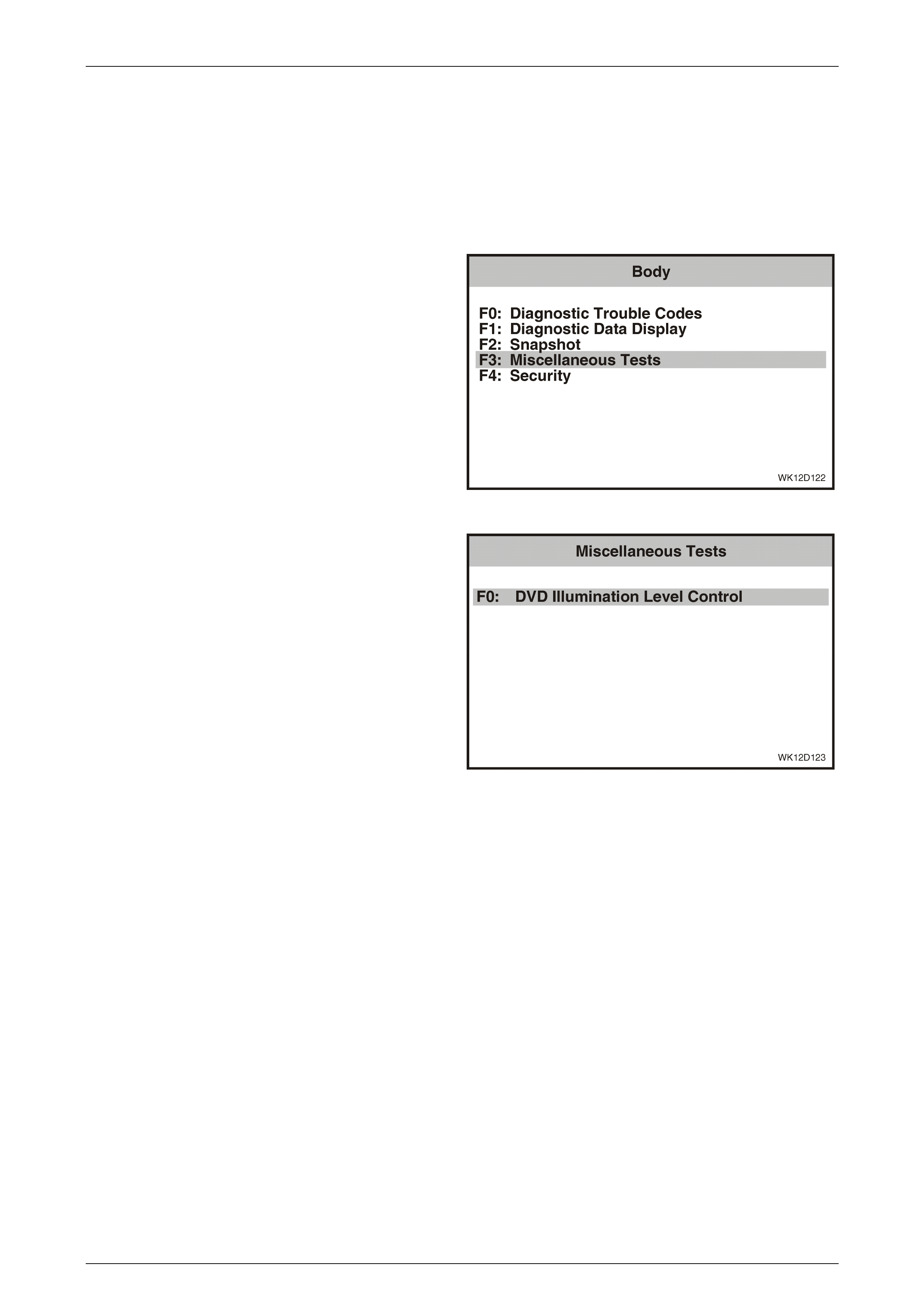
Entertainment System Page 12D–185
Page 12D–185
3.22 Miscellaneous Tests – Audio Interface
Module
The TECH 2 can be used to verify correct operation of the various functions of the audio system to assist in isolating a
fault condition. The TECH 2 can be used to force various functions on or off and monitor the response.
Note that if any test takes longer than 40 seconds to perform, the audio system will time-out and the test may have to be
started again.
1 From the Body Menu select F3: Miscellaneous Tests
and press the Enter key.
Figure 12D – 164
2 There is only one Miscellaneous Test for the audio
interface module. To proceed with this test, press the
Enter key.
Figure 12D – 165
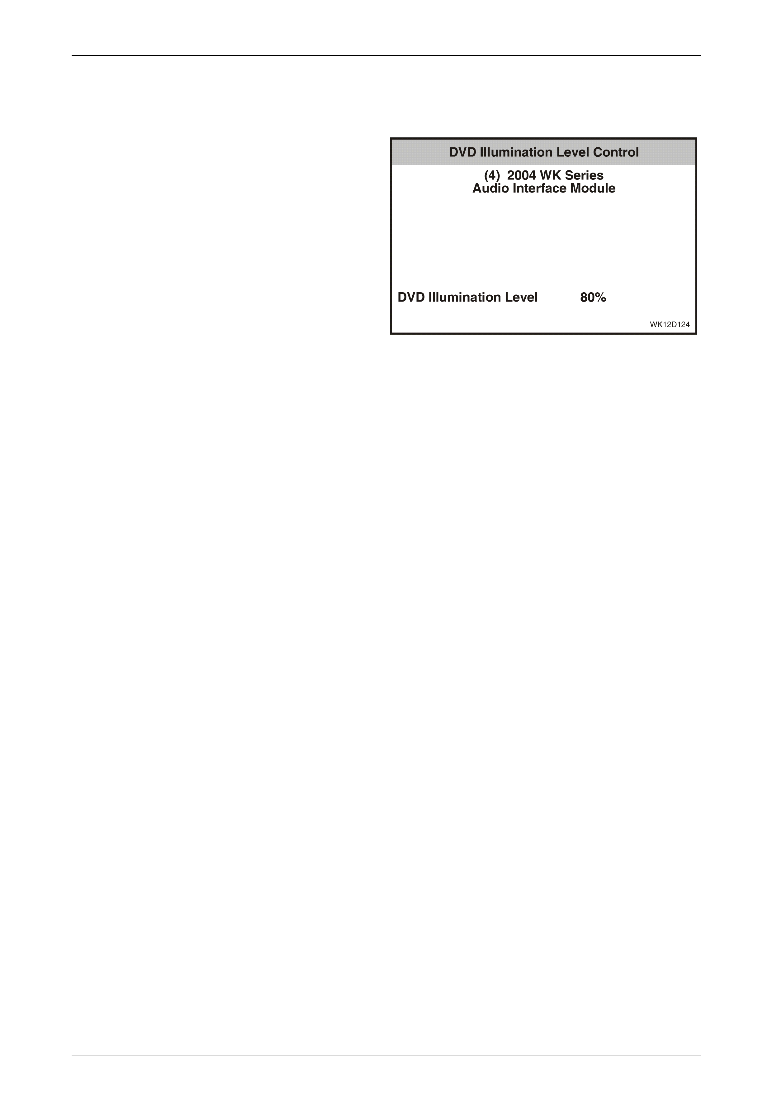
Entertainment System Page 12D–186
Page 12D–186
F0: DVD Illumination Level Control
This miscellaneous test allows you to control the DVD illumination from the Audio Interface Module. This is achieved by
using the Decrease and Increase soft keys.
1 Connect TECH 2 to the DLC. Select Diagnostics /
Model Year / Vehicle Model / Body / Audio Interface
Module / Miscellaneous Tests / DVD Illumination Level
Control.
2 The TECH 2 will display the current DVD illumination
level.
3 Press the Increase soft key on the TECH 2 and verify
that the illumination of the DVD player increases and
that the change in illumination level is reflected on the
TECH 2 screen.
4 Press the Decrease soft key on the TECH 2 and verify
that the illumination of the DVD player decreases and
that the change in illumination level is reflected on the
TECH 2 screen.
5 Press the Quit soft key to exit the test. Turn the
ignition off and then turn it back on as prompted by
TECH 2. The DVD player's illumination will default to
the level set before the test was performed.
6 If the DVD Illumination Level Control function does not
operate correctly refer to AIM Diagnostic Circuit Check
in this Section for further diagnosis.
Figure 12D – 166
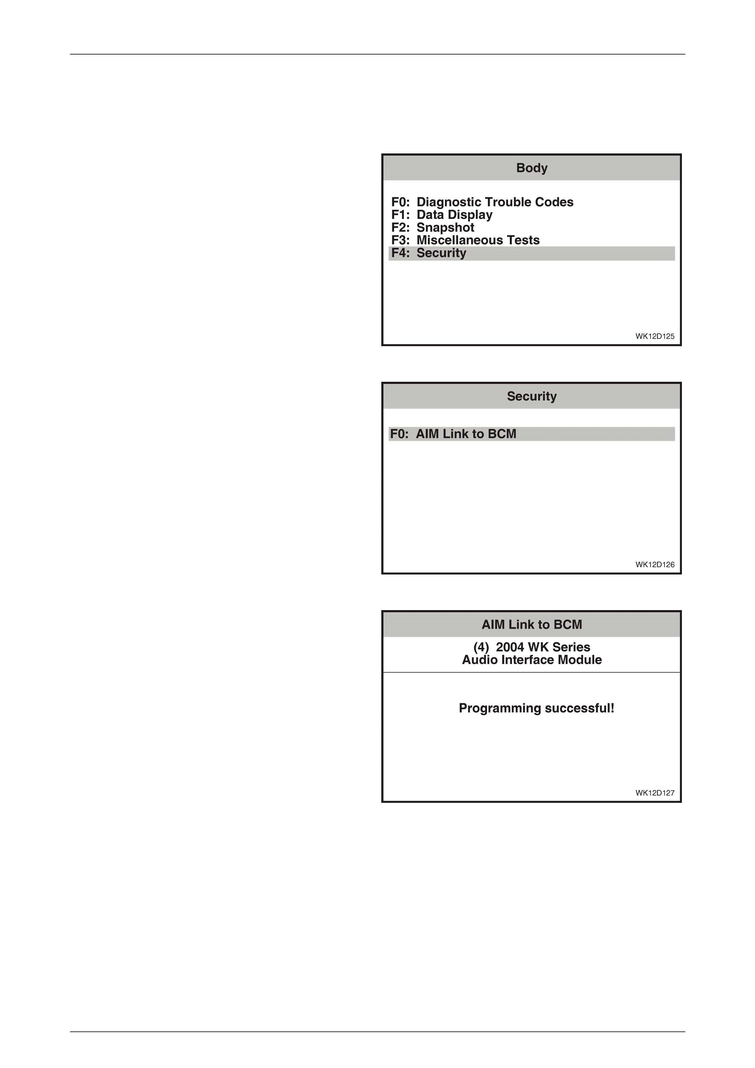
Entertainment System Page 12D–187
Page 12D–187
3.23 Security – Audio Interface Module
The Security function allows linking of the audio interface module with the BCM. The DVD player will not operate if the
AIM is not linked to the BCM.
1 From the Body Menu select F4: Security and press the
Enter key.
Figure 12D – 167
2 From the Security Menu select F0: AIM Link to BCM
and press the Enter key.
Figure 12D – 168
3 A confirmation screen will appear on TECH 2. Press
the Confirm soft key on the TECH 2 to link the AIM to
the BCM. TECH 2 will confirm that programming was
successful.
Figure 12D – 169
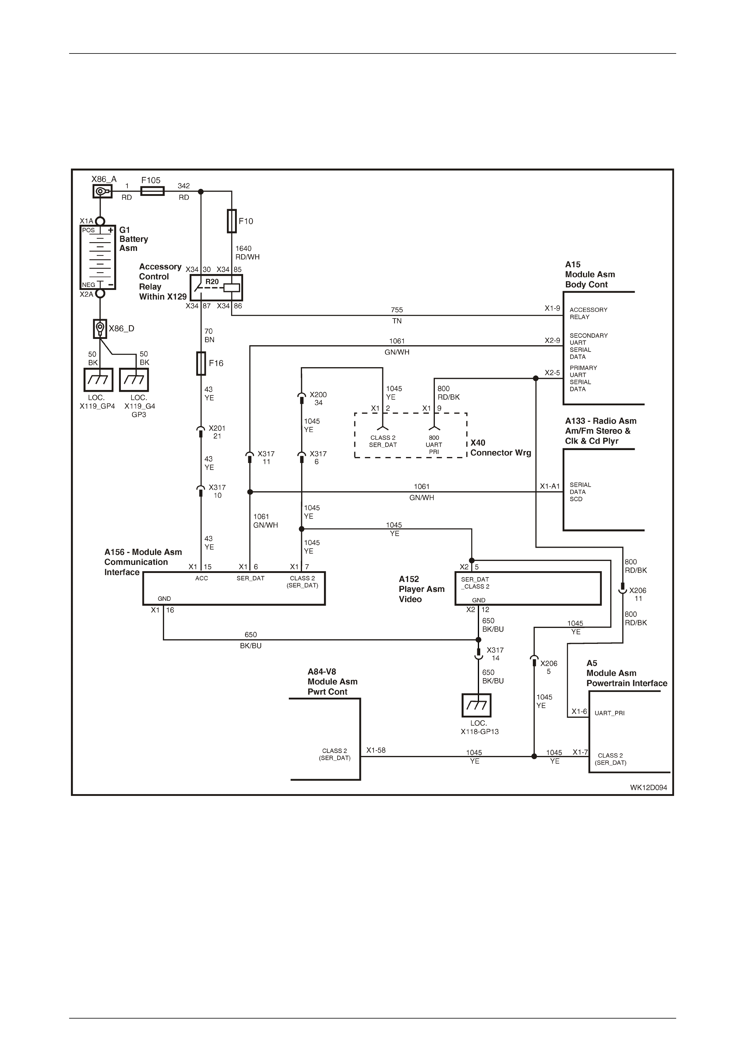
Entertainment System Page 12D–188
Page 12D–188
3.24 Audio Interface Module Diagnostic
Procedures
AI M Diagnosti c Circuit Check
Figure 12D – 170
The WK AIM enables the DVD to power up, firstly by verifying BCM security information from the Radio message on the
UART data bus, then communicates to the DVD via the Class II communications bus. The AIM will power up when the
Accessory control relay is enabled. This power source is available when the ignition is in ACC or ON position, or when
the audio head unit is switched on (Refer to Section 12J, 4.4 Accessory Power Control in the MY 2003 VY and V2 Series
Service Information for more details).
Without the valid security information, the AIM will go into Lock mode and not allow the DVD to power up.

Entertainment System Page 12D–189
Page 12D–189
NOTE
If the AIM is disconnected from the body wiring
harness (such as when the dead pan assembly is
removed) it loses its link with the BCM. To link
the AIM to the BCM refer to 3.23 Secu r i ty – A u di o
Interface Module in this Section.
The AIM also controls other DVD operations, such as Parental Lockout or Rear Roof Remote Locked and DVD
background illumination. This is done through the inputs from the audio head unit and BCM respectively via
communication on the UART data bus to the AIM, then commands are then transmitted to the DVD via the Class II bus.
AI M Diagnostic Circuit Check Diagnostic Chart
Step Action Value(s) Yes No
1 Turn the ignition on.
Connect TECH 2 to the DLC.
Select Diagnostics / Model Year / Vehicle Model / Body
/ Audio Interface Module.
Does TECH 2 display AIM identification data?
Go to Step 2. Refer to
DTC 3 – No Serial
Data From BCM
in this Section for
further diagnosis .
2 On TECH 2 se lect Diagnostic Data Display / Data List.
Is AIM linked to the BCM?
Go to Step 3 Link AIM to the
BCM. Refer to
3.23 Security –
Audio Interface
Module
in this Section.
3 On TECH 2 select Audio System / Data Display /
System Identification.
Does TECH 2 show audio system identification data?
Go to Step 4. Refer to
3.12 Audio System
Diagnostic
Procedures
in this Section for
further diagnosis .
4 On TECH 2 select Audio System / Data Display / Data
List.
Is the identifier number shown on the TECH 2 as
specified?
601 Go to Step 5. Remove AHU and
replace with a Level
5 WK series AHU.
5 Select Diagnostics / Model Year / Vehicle Model / Body
/ Audio Interface Module / Miscellaneous Tests / DVD
Illumination Level Control.
Perform the DVD illumination level control test. Refer to
3.22 Miscellaneous Tests – Audio Interface Module in
this Section.
Was the DVD illumination level con trol test succe ssful?
Go to Step 6. Refer to
DTC 41 – No
Class 2 Serial
Data from DVD
in this Section for
further diagnosis .
6 Sele ct DVD mode on the AHU.
Does the DVD player power up?
Go to Step 7. Refer to
DTC 40 – No Serial
Data from Audio
System
in this Section for
further diagnosis .
7 Select Diagnostics / Model Year / Vehicle Model / Body
/ Audio Interface Module / Diagnostic Trouble Codes /
Read Current Diagnostic Trouble Codes.
Does TECH 2 display any current DTCs?
Go to the relevant
diagnost ic tabl e in
this Section.
System OK.

Entertainment System Page 12D–190
Page 12D–190
AIM No Powe r
The AIM is supplied with power from the accessory control relay via circuit 43 to terminal X1-15. Connection to vehicle
ground is made on terminal X1-16 via circuit 650. Power to the AIM is supplied when the accessory control relay is
enabled, this power source is available when the ignition is in ACC or ON position, or when the audio head unit is
switched on.
AIM No Power Diagnostic Chart
Step Action Value(s) Yes No
1 Was the AIM Diagnostic Circuit Check performed? Go to Step 2. Go to
AIM Diagnostic
Circuit Check
in this Section.
2 Disconnect AIM connector A156 X1. Refer to
2.16 Audio Interface Module in this Section.
Reconnect the body wiring harness connector. Refer to
2.14 Dead Pan Assembly in this Section.
Using a digital voltmeter, measure the voltage between
connector A156, terminal X1-15, circuit 43 and a known
good ground.
Turn the ignition to the accessories position.
Is the voltage at the specified value?
12 V Go to Step 4. Go to Step 3.
3 Check fuse F16 and circuits 43 and 70.
Is fuse F16 and circuit 70 OK?
Refer to
Section 12J, 4.4
Accessory Power
Control
in the MY 2003 VY
and V2 Series
Service Information
for further diagnosis.
Replace fuse F16 or
repair circuit 43 or
circuit 70.
4 Using a digital ohmmeter, measure the resistance
between connector A156, terminal X1-16 circuit 650
and a known good ground.
Is the value as specified?
Continuity Replace AIM.
Refer to
2.16
A
udio Interface
Module
in this Section.
Repair open in
circuit 650.
WHEN ALL DIAGNOSIS AND REPAIRS ARE COMPLETED, VERIFY CORRECT OPERATION
DTC 1 – No Class 2 Serial Data from DVD
With the ignition in either the accessories position or the on position, DTC 1 will set to indicate that the AIM has not
received any data from the DVD for more than 10 seconds.
No Class 2 Serial Data from DVD Diagnostic Chart
Step Action Value(s) Yes No
1 Was the AIM Diagnostic Circuit Check performed? Go to Step 2. Go to
AIM Diagnostic
Circuit Check
in this Section.
2 On TECH 2 select Diagnostics / Model Year / Vehicle
Model / Body / Audio Interface Module / Diagnostic
Trouble Codes / Read Current Diagnostic Trouble
Codes.
Is DTC 1 Set?
Go to Step 3. Go to Step 7

Entertainment System Page 12D–191
Page 12D–191
Step Action Value(s) Yes No
3 Turn the ignition off.
Disconnect the TECH 2 from the DLC.
Disconnect DVD Player. Refer to 2.15 DVD Player in
this Section.
Reconnect the body wiring harness connector. Refer to
2.14 Dead Pan Assembly in this Section.
Using TECH 2, link the AIM to the BCM. Refer to
3.23 Security – Audio Interface Module in this Section.
Turn the ignition on.
Using a digital voltmeter measure the voltage between
DVD connector A152, terminal X2-5, circuit 1045 and a
known good ground.
Is the value as specified?
3 to 4 V. Refer to
DVD No Power
Diagnostics Chart
in this Section for
further diagnosis .
For vehicles with
GEN III V8 engines,
go to Step 4. For
vehicles with V6
engines, go to
Step 6.
4 Turn the ignition off.
Disconnect the Powertrain Interface Module (PIM).
Refer to Section 6C3-3 – Service Operations –
GEN III V8 Engine in the MY 2003 VY and V2 Series
Service Information.
Turn the ignition on.
Using a digital voltmeter measure the voltage between
DVD connector A152, terminal X2-5, circuit 1045 and a
known good ground.
Is there voltage as specified?
3 to 4 V. Refer to
Section 12J,
4.2 Serial Data
Communication
in the MY 2003 VY
and V2 Series
Service Information
for further diagnosis
of the PIM.
Go to Step 5.
5 Turn the ignition off.
Disconnect the Powertrain Control Module (PCM).
Refer to Section 6C3-3 – Service Operations –
GEN III V8 Engine in the MY 2003 VY and V2 Series
Service Information.
Turn the ignition on.
Using a digital voltmeter measure the voltage between
DVD connector A152, terminal X2-5, circuit 1045 and a
known good ground.
Is the voltage as specified?
3 to 4 V. Refer to
Section 6C3-
2 Diagnosis – GEN
III V8 Engine
in the MY 2003 VY
and V2 Series
Service Information
for further diagnosis
of the PCM.
Go to Step 6.
6 Turn the ignition off.
Remove the AIM. Refer to 2.16 Audio Interface Module
in this Section.
Using a digital ohmmeter back probe AIM connector
A156, terminal X1-7, circuit 1045 with a known good
ground.
Is the value as specified?
Open circuit. Go to Step 7. Repair faulty
circuit 1045.
7 Turn the ignition off.
Using a digital ohmmeter, check the continuity on
circuit 1045 between DVD connector A152, terminal
X2-5 and AIM connector A156, terminal X1-7.
Is the value as specified?
Less than
1 ohm. Replace AIM
Module. Repair faulty
circuit 1045.
WHEN ALL DIAGNOSIS AND REPAIRS ARE COMPLETED, CLEAR ALL DTCs AND VERIFY CORRECT
OPERATION

Entertainment System Page 12D–192
Page 12D–192
DTC 2 – DVD Not Initialised
With the ignition in either the accessories or the on position, DTC 2 will set to indicate that the DVD Player has failed to
initialise or respond to the AIM within 12 seconds. An 'audio thump' (loud noise through speakers) may occur if DVD
Player initialisation occurs after 12 seconds.
No Serial Data From BCM Diagnostic Chart
Step Action Value(s) Yes No
1 Was the AIM Diagnostic Circuit Check performed? Go to Step 2. Go to
AIM Diagnostic
Circuit Check
in this Section.
2 Turn the ignition on.
Select DVD mode on the AHU.
Does the DVD player power up?
Go to Step 3. Refer to
DVD No Power
Diagnostics Chart
in this Section for
further diagnosis .
3 Connect TECH 2 to the DLC.
Select Diagnostics / Model Year / Vehicle Model / Body
/ Audio Interface Module / Diagnostics Trouble Codes /
Clear DTC Information.
Clear the DTCs.
Turn the ignition off for at least five seconds and then
turn ignition on.
Select Diagnostics / Model Year / Vehicle Model / Body
/ Audio Interface Module / Diagnostics Trouble Codes /
Read Current DTC Information.
Has DTC 2 set?
Go to Step 4. System OK.
4 Repeat Step 3 two more times.
Does DTC 2 still set?
Go to Step 5. Repair short to earth
in circuit 1061.
5 Sele ct DVD mode on the AHU.
Does the DVD player power up?
Ignore DTC 2. Refer to
DVD No Power
Diagnostics Chart
in this Section for
further diagnosis .
WHEN ALL DIAGNOSIS AND REPAIRS ARE COMPLETED, VERIFY CORRECT OPERATION
DTC 3 – No Serial Data From BCM
With the ignition in either the accessories position or the on position, DTC 3 will set to indicate that the AIM has not
received any data from the BCM for more than 10 seconds. This DTC can only be read as a historical DTC as any time
the AIM module loses communications with the BCM it is not diagnosable with TECH 2.
No Serial Data From BCM Diagnostic Chart
Step Action Value(s) Yes No
1 Was the AIM Diagnostic Circuit Check performed? Go to Step 2. Go to
AIM Diagnostic
Circuit Check
in this Section.

Entertainment System Page 12D–193
Page 12D–193
Step Action Value(s) Yes No
2 Turn the ignition on.
Connect TECH 2 to the DLC.
Select Diagnostics / Model Year / Vehicle Model / Body
/ Body Control Module.
Does TECH 2 display BCM identification data?
Go to Step 3. Refer to
Section 12J Body
Control Module
in the MY 2003 VY
and V2 Series
Service Information
for further diagnosis.
3 Turn the ignition off.
Remove the AIM. Refer to 2.16 Audio Interface Module
in this Section.
Reconnect the body wiring harness connector. Refer to
2.14 Dead Pan Assembly in this Section.
Turn the ignition to accessories position.
Using a digital voltmeter measure the voltage between
AIM Connector A156, terminal X1-6, circuit 1061 and a
known good ground.
Is the voltage as specified?
3 to 4 Volts. Refer to
AIM No Power
Diagnostic Chart
in this Section for
further diagnosis .
Go to Step 4.
4 Turn the ignition off.
Using a digital ohmmeter, measure the resistance
between AIM connector A156, terminal X1-6,
circuit 1061 and a known good ground.
Is the value as specified?
Open circuit,
no continuity. Go to Step 5. Repair short to earth
in circuit 1061.
5 Turn the ignition off.
Using a digital ohmmeter, measure the resistance
between AIM connector A156, terminal X1-6,
circuit 1061 and a known good ground.
Is the value as specified?
Short circuit
to ground. Repair circuit 1061. Refer to
Section 12J Body
Control Module
in the MY 2003 VY
and V2 Series
Service Information
for further diagnosis.
WHEN ALL DIAGNOSIS AND REPAIRS ARE COMPLETED, VERIFY CORRECT OPERATION
DTC 4 – No Serial Data From Audio System
With the ignition in either the accessories position or the on position, DTC 4 will set to indicate that the AIM has not
received any data from the AHU for more than 10 seconds. This does not necessarily mean the AIM has a fault, it usually
indicates that the AHU has been removed at some point and communications lost.
No Serial Data From Audio System
Step Action Value(s) Yes No
1 Was the AIM Diagnostic Circuit Check performed? Go to Step 2. Go to AIM
Diagnostic Circuit
Check in this
Section.
2 Turn the ignition off.
Remove the AHU. Refer to 2.1 Audio System Head Unit
in this Section.
Turn the ignition on.
Using a digital voltmeter, measure the voltage between
AHU connector A133, terminal X1-A1, circuit 1061 and
a known good ground.
Is the value as specified?
Approx 3 to
4 volts. Replace the AHU.
Refer to
2.1 Audio System
Head Unit
in this Section.
Go to Step 3.

Entertainment System Page 12D–194
Page 12D–194
Step Action Value(s) Yes No
3 Disconnect AIM connector A156 X1. Refer to
2.16 Audio Interface Module in this Section.
Reconnect the body wiring harness connector. Refer to
2.14 Dead Pan Assembly in this Section.
Perform a continuity check between AIM connector
A156, terminal X1-6, circuit 1061and AHU connector
A133, terminal X1-A1.
Is there continuity?
Go to Step 4. Repair open in
circuit 1061.
4 Reconnect AIM and AHU.
Using TECH 2, link the AIM to the BCM. Refer to
3.23 Security – Audio Interface Module in this Section.
Perform an intermittent electrical fault test. Refer to
Section 12P, 4.7 Detecting Intermittent Electrical Faults
in the MY 2003 VY and V2 Series service Information.
Test the following connectors and circuits:
• Circuit 1061.
• Connector A133-X1.
• Connector A156-X1.
• Connector X317.
Was an intermittent fault detected in one of the
connect ors or circuits ?
Repair faulty circuit
or connector. Clear DTC 4.
System OK.
WHEN ALL DIAGNOSIS AND REPAIRS ARE COMPLETED, CLEAR ALL DTCs AND VERIFY CORRECT
OPERATION
DTC 7 – No Class 2 Serial Data
With the ignition in either the accessories position or the on position, DTC 7 will set to indicate that the AIM has not
received any Class II communications from any module for more than 10 seconds. This DTC can only be read as a
historical DTC as any time the AIM module loses all Class II communications it is not diagnosable with TECH 2.
If DTC 7 is set, refer to Section 12J Body Control Module in the MY 2003 VY and V2 Series Service Information for
further diagnosis .
DTC 8 – Wrong Security Code (System Locked)
With the ignition in either the accessories position or the on position, DTC 8 will set to indicate that the AIM has been
tampered with and security bypass has been attempted more than 100 times.
If DTC 8 is set, re-link the AIM to the BCM. Refer to 3.23 Security – Audio Interface Module in this Section.
DTC 11 – Class 2 Hardware Failure
With the ignition in either the accessories position or the on position, DTC 11 will set to indicate that a fault has occurred
with the AIM's ability to transmit Class II Serial Data.

Entertainment System Page 12D–195
Page 12D–195
Class 2 Hardware Failure Diagnostic Chart
Step Action Value(s) Yes No
1 Was the AIM Diagnostic Circuit Check performed? Go to Step 2. Go to
AIM Diagnostic
Circuit Check
in this Section.
2 Check the Class II serial data communications bus.
Refer to Section 12J, 4.2 Serial Data Communication
(Bus Master) in the MY 2003 VY and V2 Series Service
Information.
Is Class II serial communications bus OK?
Replace AIM.
Refer to
2.16
A
udio Interface
Module
in this Section.
Rectify fault.
Refer to
Section 12 J 4.2,
Serial Data
Communication
(Bus Master)
in the MY 2003 VY
and V2 Series
Service Information.
WHEN ALL DIAGNOSIS AND REPAIRS ARE COMPLETED, CLEAR ALL DTCs AND VERIFY CORRECT
OPERATION
DTC 12 – EEPROM Mirror Checksum Failed
With the ignition in either the accessories position or the on position, DTC 12 will set to indicate that the copy of the
EEPROM data that the module uses in normal operation has become corrupted.
EEPROM Mirror Checksum Failed Diagnostic Chart
Step Action Value(s) Yes No
1 Was the AIM Diagnostic Circuit Check performed? Go to Step 2. Go to
AIM Diagnostic
Circuit Check
in this Section.
2 Connect TECH 2 to the DLC.
Select Diagnostics / Model Year / Vehicle Model / Body
/ AIM / Diagnostic Trouble Codes / Clear DTC
Information.
Clear the DTCs.
Turn the ignition off for at least five seconds and then
turn ignition on.
Select Diagnostics / Model Year / Vehicle Model / Body
/ AIM / Diagnostic Trouble Codes / Read Current DTC
Information.
Has DTC 12 set?
Go to Step 3. System OK.
3 Repeat step 1 twice more.
Does DTC 12 still set?
Replace AIM.
Refer to
2.16
A
udio Interface
Module
in this Section.
System OK.
WHEN ALL DIAGNOSIS AND REPAIRS ARE COMPLETED, CLEAR ALL DTCs AND VERIFY CORRECT
OPERATION
DTC 13 – EEPROM Checksum Failed
With the ignition in either the accessories position or the on position, DTC 13 will set to indicate that the EEPROM data
the module uses has become corrupted.
If DTC 13 is set, replace the AIM. Refer to 2.16 Audio Interface Module in this Section.

Entertainment System Page 12D–196
Page 12D–196
3.25 Diagnostic Trouble Codes – DVD Player
1 From the Body Menu select F0: Diagnostic Trouble
Codes and press the Enter key.
Figure 12D – 171
2 Using the TECH 2 Up and Down arrows, select the
required item and then press the Enter key.
F0: Read Current DTC Information. If this mode is
selected, a listing of all (if any) DTC that have been set by
the audio system will be displayed.
F1: Clear DTC Information. DTC can be cleared in this
mode by simply selecting F1: Clear DTC Information,
pressing the Enter key on TECH 2 and confirming the action
as instructed by TECH 2.
NOTE
TECH 2 will display Clear DTC Information, or
Failed if any DTC are still current.
Figure 12D – 172
Read Current DTC Inf orma tion
If any DTCs are set, reference should be made to the
relevant diagnostic charts in this Section.
Figure 12D – 173
DVD Player Diagnostic Trouble Code List
DTC B1000 DVD Player Malfunction DTC U1301 Class 2 Serial Data Circuit Voltage High
DTC U1300 Class 2 Serial Data Circuit Voltage Low DTC U1128 No Audio Interface Module Serial Data
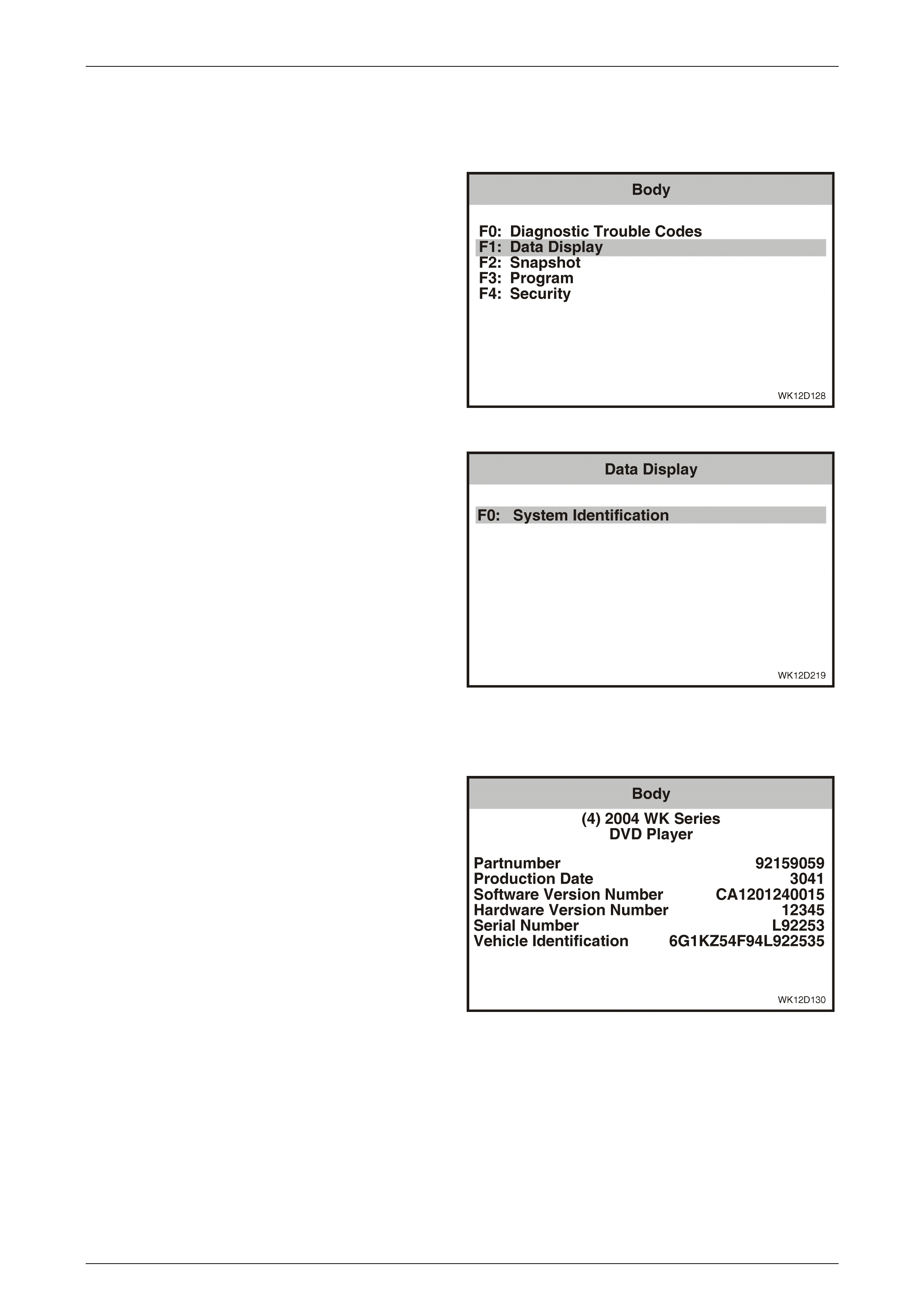
Entertainment System Page 12D–197
Page 12D–197
3.26 Data Display – DVD Player
The Data Display function allows the DVD Player system identification details to be viewed.
1 From the Body Menu select F1: Data Display and
press the Enter key.
Figure 12D – 174
2 There is only one selection available, F0:System
Identification. To proceed, press the Enter key.
Figure 12D – 175
F0: System Identification
The System Identification screen provides production
information relevant to the DVD player.
Figure 12D – 176

Entertainment System Page 12D–198
Page 12D–198
3.27 Snapshot – DVD Player
1 From the Body Menu select F2: Snapshot and press
the Enter key.
Figure 12D – 177
2 The TECH 2 can be used to record system information
that is occurring at a particular moment in time, and
this is called a snapshot. For more details, refer to The
TECH 2 User's Guide.
Figure 12D – 178
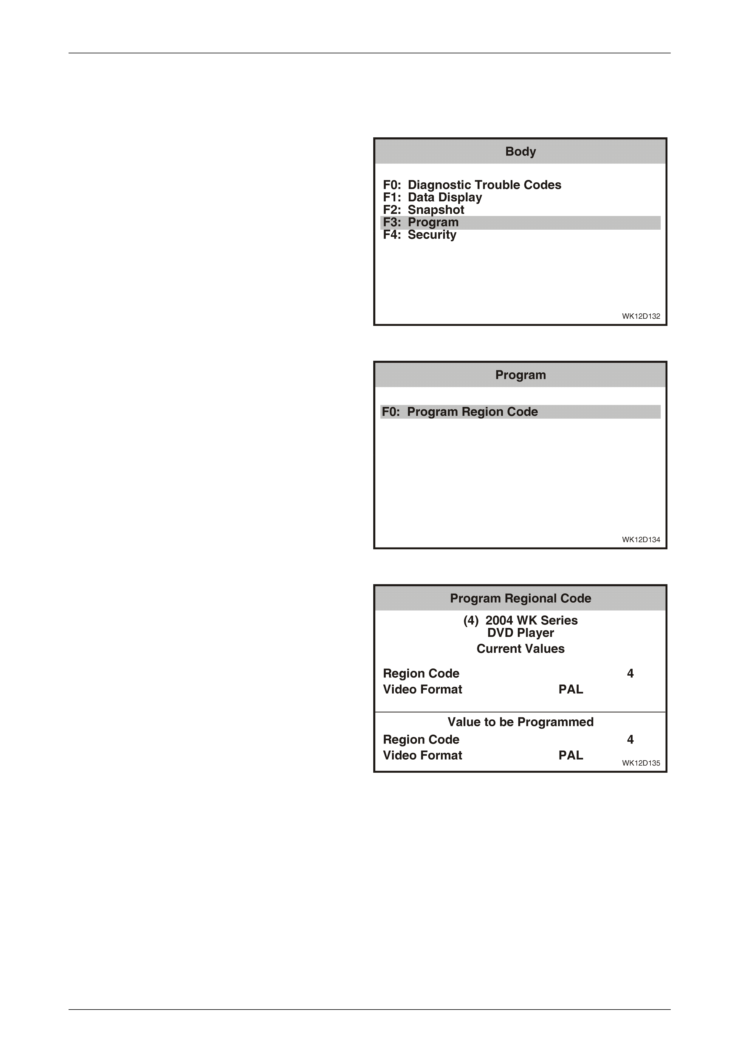
Entertainment System Page 12D–199
Page 12D–199
3.28 Program – DVD Player
The Program function allows the programming of the DVD player region code and video format.
1 From the Body Menu select F3: Program and press
the Enter key.
Figure 12D – 179
2 Ensure a disc is not loaded in the DVD player and
then select F0: Program Region Code from the
Program Menu and press the Enter key.
Figure 12D – 180
2 The Region Code and Video Format to be
programmed are displayed. Press the Program soft
key. To exit without making a change, press the Okay
soft key.
Figure 12D – 181

Entertainment System Page 12D–200
Page 12D–200
3 TECH 2 will confirm successful programming of the
DVD player.
Figure 12D – 182

Entertainment System Page 12D–201
Page 12D–201
3.29 Security – DVD Player
The Security function allows linking and unlinking of the audio interface module with the BCM. The DVD player will not
operate if the AIM is not linked to the BCM.
1 From the Body Menu select F4: Security and press the
Enter key.
Figure 12D – 183
2 From the Security Menu select F0: AIM Link to BCM
and press the Enter key.
Figure 12D – 184
3 A confirmation screen will appear on TECH 2. Press
the Confirm soft key on the TECH 2 to link the AIM to
the BCM. TECH 2 will confirm that programming was
successful.
Figure 12D – 185

Entertainment System Page 12D–202
Page 12D–202
3.30 DVD Player Diagnostic Procedures
DVD Diagnosti c Circuit Check
Figure 12D - 186
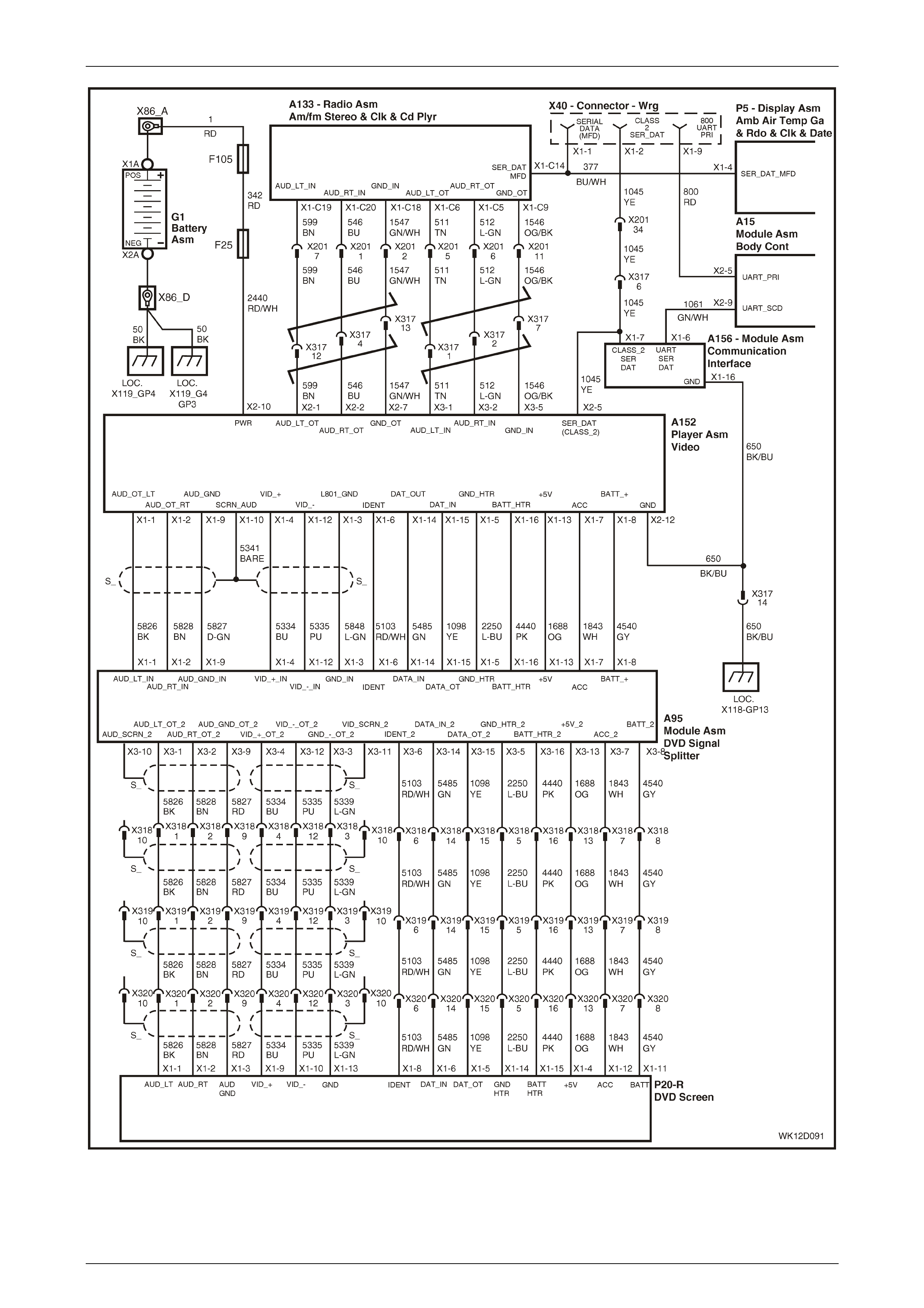
Entertainment System Page 12D–203
Page 12D–203
Figure 12D – 187

Entertainment System Page 12D–204
Page 12D–204
The WK AIM enables the DVD to power up, firstly by verifying BCM security information from the Radio message on the
UART data bus, then communicates to the DVD via the Class II communications bus. If BCM security information is
verified, the DVD player will power up when the Accessory control relay is enabled. This power source is available when
the ignition is in ACC or ON position, or when the audio head unit is switched on (Refer to Section 12J, 4.4 Access ory
Power Control in the MY 2003 VY and V2 Series Service Information for more details).
Without the valid security information, the AIM will go into Lock mode and not allow the DVD to power up.
The DVD player communicates with TECH 2 via the AIM. If the AIM is not functioning, diagnosis of the DVD player via
TECH 2 is not possible. For this reason, all diagnosis of the DVD player must begin by verifying that the AIM is fully
functional.
NOTE
If the AIM is disconnected from the body wiring
harness (such as when the dead pan assembly is
removed) it loses its link with the BCM. To link
the AIM to the BCM refer to 3.23 Secu r i ty – Au di o
Interface Module in this Section.
DVD Diagnostic Circuit Check Diagnostic Chart
Step Action Value(s) Yes No
1 Was the AIM Diagnostic Circuit Check performed? Go to Step 2. Go to
AIM Diagnostic
Circuit Check
in this Section.
2 Turn the ignition on.
Turn the audio head unit on.
Select DVD mode on the AHU.
Insert a DVD of the correct region code into the DVD
player and press play. If the region code for the DVD
player has not been programmed, refer to
3.28 Program – DVD Player in this Section.
Does sound from the DVD come through the audio
system?
Go to Step 3. Refer to
DVD Player No
Sound Diagnostic
Chart
in this Section for
further diagnosis .
3 Is the DVD picture shown on both video screens? Go to Step 4. Go to
DVD Player No
Picture Diagnostic
Chart
in this Section for
further diagnosis .
4 Connect TEHC 2 to the DLC.
Select Diagnostics / Model Year / Vehicle Model / Body
/ DVD Player / Diagnostic Trouble Codes / Read
Current DTC Information.
Are any current DTCs displayed?
Go to relevant DTC
diagnost ic tabl e in
this Section.
System OK.
WHEN ALL DIAGNOSIS AND REPAIRS ARE COMPLETED, VERIFY CORRECT OPERATION

Entertainment System Page 12D–205
Page 12D–205
DVD No Power
The DVD player is supplied with power from the accessory control relay via circuit 2440 to terminal X2-10. Connection to
vehicle ground is made on terminal X2-12 via circuit 650. Power to the DVD player is supplied when the accessory
control relay is enabled and the AIM verifies the security information from the BCM. The accessory control relay is
enabled when the ignition is in ACC or ON position, or when the audio head unit is switched on.
DVD No Power Diagnostic Chart
Step Action Value(s) Yes No
1 Was the DVD Diagnostic Circuit Check performed? Go to Step 2. Go to
DVD Diagnost ic
Circuit Check
in this Section.
2 Disconnect DVD connector A152-X2. Refer to
2.15 DVD Player in this Section.
Reconnect the body wiring harness connector. Refer to
2.14 Dead Pan Assembly in this Section.
Using TECH 2, link the AIM to the BCM. Refer to
3.23 Security – Audio Interface Module in this Section.
Using a digital voltmeter, measure the voltage between
DVD connector A152, terminal X2-10, circuit 2440 and
a known good ground.
Is the value as specified?
12V Go to Step 4. Go to Step 3.
3 Check fuse F25 and circuit 342.
Is fuse F25 and circuit 342 OK?
No battery power to
circuit 342 or
fuse F25. Check
circuits 1 and 342 to
fuse F25 and repair
fault in circuit.
Repair circuit 342 or
fuse F25.
4 Using a digital ohmmeter, measure the resistance
between DVD connector A152, terminal X2-12,
circuit 650 and a known good ground.
Is the value as specified
Less than
1 Ohm Replace DVD
player. Refer to
2.15 DVD Player
in this Section.
Repair circuit 650.
WHEN ALL DIAGNOSIS AND REPAIRS ARE COMPLETED, VERIFY CORRECT OPERATION
DVD No Sound
DVD sound is transmitted through the WK audio system when DVD mode is selected on the audio head unit or rear roof
remote control. If the audio system is not functioning, DVD sound can only be heard through the stereo RCA jacks
mounted on the faceplate of the DVD player.
DVD Player No Sound Diagnostic Chart
Step Action Value(s) Yes No
1 Has the DVD Diagnostic Circuit Check been
performed? Go to Step 2. Perform
DVD Diagnost ic
Circuit Check .
2 Turn the audio head unit on and select the radio mode.
Is there sound from the speakers?
Go to Step 3. Refer to
3.12 Audio System
Diagnostic
Procedures
in this Section for
further diagnosis .
3 Select DVD mode on the AHU and play a DVD.
Is there sound from the speakers?
System OK. Go to Step 4

Entertainment System Page 12D–206
Page 12D–206
Step Action Value(s) Yes No
4 Plug in a set of headphones to the DVD player fascia.
Select DVD mode and play a DVD.
Is there sound from the headphones?
Go to Step 5. Go to Step 6.
5 Perform an intermittent electrical fault test. Refer to
Section 12P, 4.7 Detecting Intermittent Electrical Faults
in the MY 2003 VY and V2 Series Service Information.
Test the following connectors and circuits between the
audio head unit and the DVD player:
• Circuit 599.
• Circuit 546.
• Circuit 1547.
• Circuit 511.
• Circuit 512.
• Circuit 1546.
• Connector A133-X1.
• Connector A152-X2.
• Connector A152-X3.
• Connector X317.
• Connector X201.
Was an intermittent fault detected in one of the
connect ors or circuits ?
Repair faulty
connector or circuit. DVD player OK.
Refer to
3.12 Audio System
Diagnostic
Procedures
in this Section for
further diagnosis .
6 Check DVD player connectors A152-X2 and A152-X3,
AHU connector A133-X1 and main body wiring harness
connectors X317 and X201.
Are connectors OK?
Replace DVD
player. Refer to
2.15 DVD Player
in this Section.
Repair loose or
faulty connector.
WHEN ALL DIAGNOSIS AND REPAIRS ARE COMPLETED, VERIFY CORRECT OPERATION
DVD Player No Picture
DVD picture is displayed on the two video screens mounted into the rear of the front seat head restraints. A problem with
picture on both screens, suggests a fault with either the DVD player, DVD splitter or the connections between the two. If
the problem is confined to one screen, then the connection between the DVD splitter and the affected screen or the
screen itself are the most likely sources of the fault.
DVD Player No Picture Diagnostic Chart
Step Action Value(s) Yes No
1 Has the DVD Diagnostic Circuit Check been
performed? Go to Step 2. Perform
DVD Diagnost ic
Circuit Check .
2 Turn the ignition on.
Select DVD mode on the AHU and play a DVD.
Is there a picture on both video screens?
System OK. Go to Step 3.
3 Is there a picture on one screen? Go to Step 4. Go to Step 5.

Entertainment System Page 12D–207
Page 12D–207
Step Action Value(s) Yes No
4 Check connectors A152-X1, A95-X1, A95-X3, X318,
and X320 (RH video screen) or A152-X1, A95-X1,
A95-X2, X319 and X320 (LH video screen).
Are the connectors OK?
Replace faulty LH or
RH video screen.
Refer to Section
1A7 Seat
Assemblies in this
Service Information.
Repair faulty or
loose connector.
5 Check connectors A152-X1, A95-X1, A95-X2, A95-X3,
X318, X319, and X320 (RH video screen only).
Are the connectors OK?
Replace DVD
player. Refer to
2.15 DVD Player
in this Section.
Repair faulty or
loose connector.
WHEN ALL DIAGNOSIS AND REPAIRS ARE COMPLETED, VERIFY CORRECT OPERATION
DTC B1000 – DVD Player Malfunction
With the ignition in either the accessories position or the on position, DTC B1000 will set to indicate a malfunction in the
ECU or that the EEPROM data the DVD player uses has become corrupted.
If DTC 13 is set, replace the DVD player. Refer to 2.15 DVD Player in this Section.
DTC U1300 – Class 2 Serial Data Circuit Voltage Low
With the ignition in either the accessories position or the on position, DTC U1300 will set to indicate a short to ground on
circuit 1045. This DTC can only be read as a historical DTC as any time the DVD player loses Class II communications
with the AIM it is not diagnosable with TECH 2.
DTC U1300 – Class 2 Serial Data Circuit Voltage Low Diagnostic Chart
Step Action Value(s) Yes No
1 Was the AIM Diagnostic Circuit Check performed? Go to Step 2. Go to
AIM Diagnostic
Circuit Check
in this Section.
2 Connect TEHC 2 to the DLC.
Select Diagnostics / Model Year / Vehicle Model / Body
/ DVD Player / Diagnostic Trouble Codes / Clear DTC
Information.
Clear DTC U1300 and perform the DVD Diagnostic
Circu it Check as detailed in this S ection.
Is DTC U1300 again displayed as a historical DTC?
Refer to
DTC 1 – No
Class 2 Serial
Data from DVD
in the AIM
diagnostics in this
Section for further
diagnosis.
System OK.
WHEN ALL DIAGNOSIS AND REPAIRS ARE COMPLETED, VERIFY CORRECT OPERATION

Entertainment System Page 12D–208
Page 12D–208
DTC U1301 – Class 2 Serial Data Circuit Voltage High
With the ignition in either the accessories position or the on position, DTC U1301 will set to indicate a short to voltage on
circuit 1045. This DTC can only be read as a historical DTC as any time the DVD player loses Class II communications
with the AIM it is not diagnosable with TECH 2.
DTC U1301 – Class 2 Serial Data Circuit Voltage High Diagnostic Chart
Step Action Value(s) Yes No
1 Was the AIM Diagnostic Circuit Check performed? Go to Step 2. Go to
AIM Diagnostic
Circuit Check
in this Section.
2 Connect TEHC 2 to the DLC.
Select Diagnostics / Model Year / Vehicle Model / Body
/ DVD Player / Diagnostic Trouble Codes / Clear DTC
Information.
Clear DTC U1301 and perform the DVD Diagnostic
Circu it Check as detailed in this S ection.
Is DTC U1301 again displayed as a historical DTC?
Refer to
DTC 1 – No
Class 2 Serial
Data from DVD
in the AIM
diagnostics in this
Section for further
diagnosis.
System OK.
WHEN ALL DIAGNOSIS AND REPAIRS ARE COMPLETED, VERIFY CORRECT OPERATION
DTC U1128 No Audi o Interface Module Serial Data
With the ignition in either the accessories position or the on position, DTC U1128 will set to indicate that the DVD player
has not received any Class II communications from the AIM for more than 10 seconds. This DTC can only be read as a
historical DTC as any time the DVD player loses Class II communications with the AIM it is not diagnosable with TECH 2.
DTC U1128 No Audio Interface Module Serial Data Diagnostic Chart
Step Action Value(s) Yes No
1 Was the AIM Diagnostic Circuit Check performed? Go to Step 2. Go to
AIM Diagnostic
Circuit Check
in this Section.
2 Connect TEHC 2 to the DLC.
Select Diagnostics / Model Year / Vehicle Model / Body
/ DVD Player / Diagnostic Trouble Codes / Clear DTC
Information.
Clear DTC U1128 and perform the DVD Diagnostic
Circu it Check as detailed in this S ection.
Is DTC U1128 again displayed as a historical DTC?
Refer to
DTC 1 – No
Class 2 Serial
Data from DVD
in the AIM
diagnostics in this
Section for further
diagnosis.
System OK.
WHEN ALL DIAGNOSIS AND REPAIRS ARE COMPLETED, VERIFY CORRECT OPERATION

Entertainment System Page 12D–209
Page 12D–209
4 Specifications
VY System 1 Entertainment S ystem
Radio / CD Player………………………………………….. AM / FM Stereo Tuner / Single CD Player
Power Output………………………………………………. 60 watts
Speakers
Type
– Instrument Panel mounted…………………… Two speakers – instrument fascia mounted tweeters
– Front Door……………………………………... Two speakers – front door trim mounted 150 mm full range
dual cone
– Rear Door……………………. Two speakers – rear door trim mounted 150 mm full range
dual cone
Impedance…………………………………………………. Ins trument panel speakers – 2 ohms
Front and rear door speakers – 4 ohms
VY System 3b Entertainment System
Radio / CD Player………………………………………….. AM/FM Stereo Tuner / Six Disc CD Changer
Power Output………………………………………………. 60 watts
Speakers
Type
– Instrument Panel mounted…………………… Two speakers – instrument panel mounted tweeters
– Front Door……………………………………... Two speakers – front door trim mounted 150 mm full range
dual cone
– Rear Door………………...……………………. Two speakers – rear door trim mounted 150 mm full range
dual cone
Impedance…………………………………………………. Ins trument panel speakers – 2 ohms
Front and rear door speakers – 4 ohms
WK System 3a Entertainment System
Radio / CD Player………………………………………….. AM/FM Stereo Tuner / Six Disc CD Changer
Power Output………………………………………………. Head unit – 120 watts
Subwoofer amplifier 2 x 70 watts max
Speakers
Type
– Instrument Panel mounted…………………… Two speakers – instrument panel mounted tweeters
– Front Door……………………………………... Two speakers – front door trim mounted 150 mm full range
dual cone
– Rear Door………………...……………………. Two speakers – rear door trim mounted 150 mm full range
dual cone
– Rear Parcel Shelf……………………………... Two speakers – rear parcel shelf mounted 200 mm
subwoofer
Impedance…………………………………………………. All speakers – 2 ohms
WK System 4 Entertainment System
Radio / CD Player………………………………………….. AM/FM Stereo Tuner / Six Disc CD Changer
Power Output………………………………………………. Head unit – 260 watts
Subwoofer amplifier 2 x 70 watts max
Speakers
Type
– Instrument Panel mounted…………………… Two speakers – instrument fascia mounted tweeters
– Front Door……………………………………... Two speakers – front door trim mounted 150 mm full range
dual cone
– Rear Door………………...……………………. Two speakers – rear door trim mounted 150 mm full range
co-axial
– Rear Parcel Shelf……………………………... Two speakers – rear parcel shelf mounted 200 mm
subwoofer
Impedance…………………………………………………. All speakers – 2 ohms

Entertainment System Page 12D–210
Page 12D–210
WK System 6 Entertainment System
Radio / CD Player………………………………………….. AM/FM Stereo Tuner / Six Disc CD Changer
Power Output………………………………………………. Head unit – 430 watts
Subwoofer amplifier 2 x 70 watts max
Speakers
Type
– Instrument Panel mounted…………………… Two speakers – instrument panel mounted tweeters
– Front Door……………………………………... Two speakers – front door trim mounted 150 mm full range
dual cone
– Rear Door………………...……………………. Two speakers – rear door trim mounted 150 mm full range
co-axial
– Rear Parcel Shelf……………………………... Two speakers – rear parcel shelf mounted 200 mm
subwoofer
Impedance…………………………………………………. All speakers – 2 ohms
Program Code Index Numbers
For the MY 2004 WK Series code index specifications, refer to 3.11 Program – Audio System in this Section.
Audio System Identifier Number
The system identifier number is displayed on TECH 2. This number identifies the audio system installed.
System Identifier
Number Audio S ystem Vehicle
000 Unidentified Chevrolet Caprice LS (LHD)
102 VY System 1 Chevrolet Caprice LTZ (LHD)
306 VY System 3B Chevrolet Caprice SS (LHD)
311 WK System 3A Chevrolet Caprice Royale (LHD)
411 WK System 4 Holden Statesman
601 WK System 6 Holden Caprice

Entertainment System Page 12D–211
Page 12D–211
5 Torque Wrench Specifications
Instrument Panel Speaker Retaining Screw (all models).....................................1.0 – 3.0 Nm
Defroster Grille Retaining Screw..........................................................................1.0 – 3.0 Nm
Instrument Panel Outer Cover Retaining Screw...................................................1.0 – 3.0 Nm
Front Door Speaker Retaining Screw (all models)...............................................1.0 – 3.0 Nm
Rear Door Speaker Retaining Screw (all models)................................................1.0 – 3.0 Nm
Subwoofer Speaker Retaining Screw...................................................................1.0 – 3.0 Nm
Rear Quarter Speaker to Mounting Bracket
Retaining Sc rew...................................................................................................1.0 – 3.0 Nm
Speaker Mounting Box to Rear Parcel Shelf
Retaining Sc rew...................................................................................................1.0 – 3.0 Nm
Rear Parcel Shelf Speaker to Mounting Box
Retaining Sc rew...................................................................................................1.5 – 3.0 Nm
Antenna Bracket to Inner Fender Panel
Retaining Bolt...................................................................................................14.5 – 19.5 Nm
Power Antenna Ground Braid to Inner Fender Screw..........................................1.0 – 3.0 Nm
Power Antenna to Mounting Bracket
Retaining Nuts....................................................................................................5.0 – 12.0 Nm
Diversity Antenna Module to Parcel Shelf Attaching Screw.................................1.0 – 3.0 Nm
Diversity Antenna Grounding Screw....................................................................1.0 – 3.0 Nm
Stereo Switch to Steering Wheel Retaining Screw...............................................1.0 – 3.0 Nm
Subwoofer Amplifier Attaching Screw..................................................................0.5 – 1.5 Nm
Child Seat Anchor Attaching Screw.................................................................15.0 – 25.0 Nm
Rear Remote Control Attaching Screw ................................................................1.0 – 3.0 Nm
Rear Audio Headphone Jacks Attaching Nut........................................................ Finger Tight
Roof Mounted Speaker Attaching Screw .............................................................1.0 – 3.0 Nm
Premium Sound Amplifier Mounting Bracket Attaching Screw.............................2.0 – 4.0 Nm
Premium Sound Amplifier Attaching Screw ...................................................................0.9 Nm
Dead Pan Assembly Attaching Bolt.................................................................30.0 – 50.0 Nm
DVD Player Mounting Bracket Attaching Bolt ..................................................0.65 – 0.95 Nm
Audio Interface Module Attaching Screw .............................................................2.0 – 4.0 Nm
DVD Splitter Attaching Screw...............................................................................2.0 – 4.0 Nm
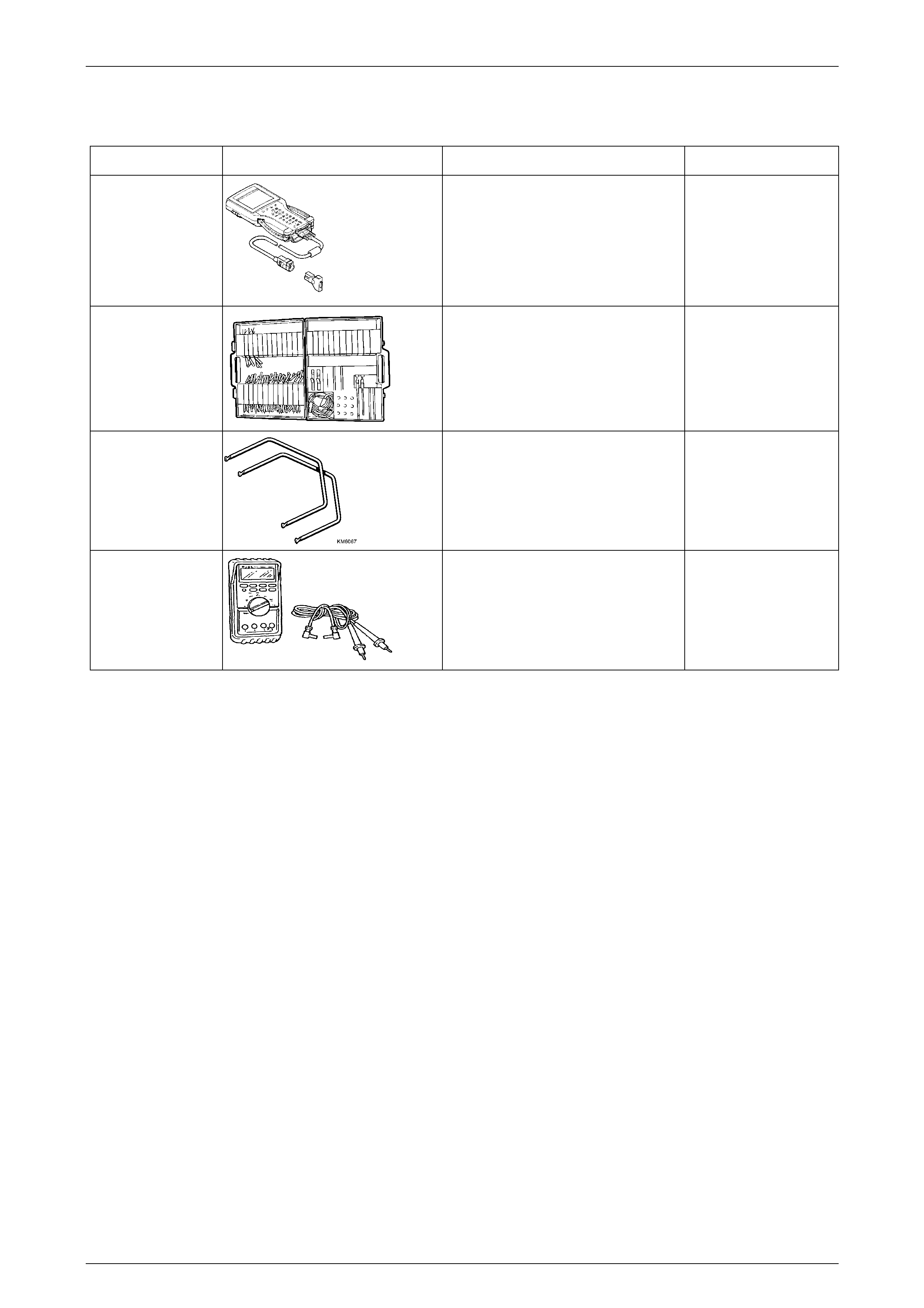
Entertainment System Page 12D–212
Page 12D–212
6 Special Tools
Tool Number Illustration Description Tool Classification
7000086I
TECH 2
DIAGNOSTIC SCAN TOOL
Used for diagnosis of vehicle electrical
system.
Previously released.
Mandatory
J35616-A
(KM609)
CONNECTOR TEST ADAPTOR KIT
Used when carrying out electrical
diagnost ic cir cui t chec ks.
Previously released.
Desirable
KM6067
RADIO REMOVAL TOOLS
Used for removing the audio head unit
from it’s mounting location.
Previously released.
Mandatory
3588
(J39200)
DIGITAL MULTIMETER
Must have at least 10 MΩ inpu t
impedance and be capa ble of reading
frequencies.
Previously released.
Available

Revised February 2003
BLAUPUNKT AUDIO REPLACEMENT / REPAIR
AUTHORISATION REQUEST FORM
Date: ……………….. Time: -………… am/pm Dealer Code: ……..…… Warranty: YES / NO
Contact Name:………………………… Dealer Name: ………………………………………….………………..……..
Phone No.: (………)………………… Dealer Address: ……………………………………………………………….
Fax No.: (………)……..……………… ……………………………………………………………………………………
R / O No:-……..………………… …………………………………………………………………………………….
Service Manager or Nominee Signature: ……………………………………………..……………………………………
Vehicle Detail s:
ISOVIN: ……………………………………………………. TAG No……………………………. Delivery Date:-………………….
Build Date: ……………………… Odometer:…………. Vehicle Model Code: eg VY Berlina, TS CD, JS etc. ………………
Audio System Details:
Holden Part Number
9………………………………..
Blaupunkt Serial Number of failed unit eg BP8382W0608664
BP…………………………..………………………………
Component Description: eg VY Acclaim single CD, JS CD Changer: …………………………………………………………
CD’s stuck inside? Yes No If Yes, complete CD ENCLOSED form and fax with the PRIOR APPROVAL FORM
AND attach a copy to the radio.
Is there any physical damage or modifications done to the unit? YES / NO (Please circle)
A. CUSTOMER COMPL AINT DETAILS
………………………………………………………………………………………………………………………
B. TITLE of DIAGNOSIS CHART(S) USED ie “Radio Illumination”
…………………………………………………………………………………..
Stored DTC’s.
C. FAULT DIAGNOSIS STEPS COMPLETED (insert applicable steps – refer Diagnosis Procedure)
D. DIAGNOSIS COMMENTS
………………………………………………………………………………………………………………………
NOTE: For Diagnostic assistance, please call Blaupunkt Service Centre on 1300 30 70 36.
Please return faul ty uni t using the provided return con signment note and origi nal shipping
carton. To book courier, please call Mayne on 131 531, accou nt number 3006ZT.
AUTHORISATION NUMBER (Blaupunkt to provide)
……………………………
FAX this completed for m to Blaupu nkt on (03) 9541 5432

Revised February 2003
CDs ENCLOSED
ATTENTION: This unit contain s Customer’s CDs. Please be extra careful with them, the
customer would like them back as soo n as possible.
Serial number of Radio/CD: BP
The following CDs are thought to be inside;
Eg. Queen – Greatest Hits
1
2
3
4
5
6
We woul d like the CDs returned to the following address;
Name: Phone: ( )
Address:
Suburb: State:
Post Code:
Returned by: (please p ri nt)
Dealership:
Date:
Blaupu nkt Service u se: CDs removed:
1
2
3
4
5
6
Technician: Date:
Returned to abo ve on: (date)
Consignment Note:
Include this form with the faxed BLAUPUNKT AUDIO REPLACEMENT/REPAIR
AUTHORISATION REQUEST FORM, AND attach it to the unit being returned.
Please provide the Customer with a copy of this completed form, it is their
receipt for tracki ng the CDs.