
Reverse Park ing Aid Page 12F–1
01–DEC–2002 Page 12F–1
Section 12F
Reverse Parking Aid
ATTENTION
Before performing any Service Operation or other procedure described in this Section, refer to Section 00
WARNINGS, CAUTIONS AND NOTES for correct workshop practices with regard to safety and/or property
damage.
1 General Information............................................................................................................................... 2
1.1 Components ...........................................................................................................................................................2
Rear Compartment.................................................................................................................................................2
Rear Bumper Fascia...............................................................................................................................................3
2 Diagnosis................................................................................................................................................ 4
2.1 Sensor Circuit Test ................................................................................................................................................4
Techline
Reverse Park ing Aid Page 12F–2
01–DEC–2002 Page 12F–2
1 General Information
With the following exceptions, MY 2004 WK Series Reverse Parking Aid information carries over from MY 2003 VY
Series vehicles. For information not contained within this Section, refer to Section 12F REVERSE PARKING AID in the
MY 2003 VY and V2 Series Service Information.
• Connector X905 is different in the MY 2004 WK Series from the MY 2003 VY and V2 Series vehicles.
1.1 Components
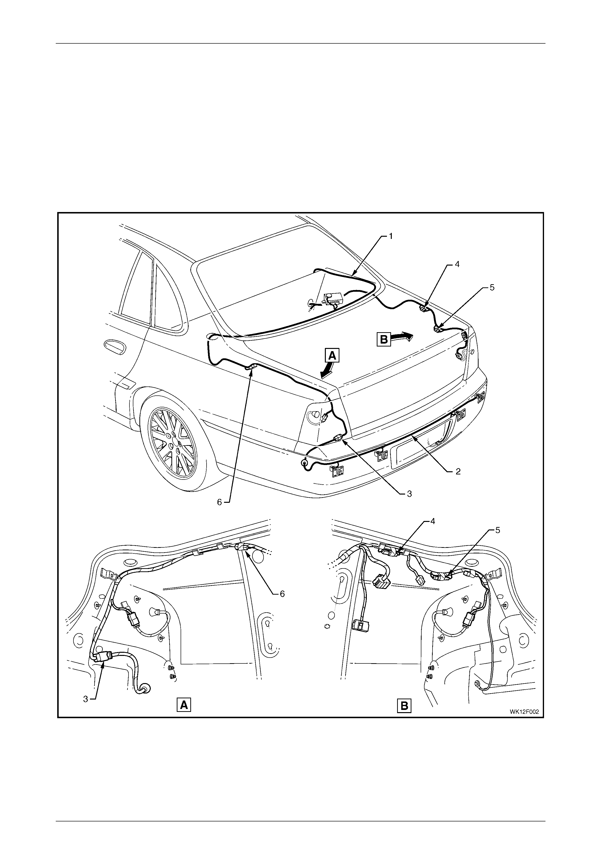
Rear Compartment
Figure 12F – 1
Legend
1 Body Wiring Harness
2 Rear Object Sensor Harness
3 Rear Object Sensor t o Body Harness Connector X905
4 Towbar Tongue Modification Connector X906 (white)
5 Trailer Harnes s Connector X907 (black)
6 Diagnosi s Connec tor X156

Reverse Park ing Aid Page 12F–3
01–DEC–2002 Page 12F–3
Rear Bumper Fascia
Figure 12M – 2
Legend
1 Rear Object Sensor Connecto r
2 Rear Object Sensor Assembl y
3 Rear Object Sensor Housing
4 Rear Object Sensor Ring
5 Clips (4 pl ac es)
6 Wiring Harness
Reverse Park ing Aid Page 12F–4
01–DEC–2002 Page 12F–4
2 Diagnosis
For diagnostics that are not detailed in this section, refer to Section 12F REVERSE PARKING AID in the MY 2003 VY
and V2 Series Service Information.
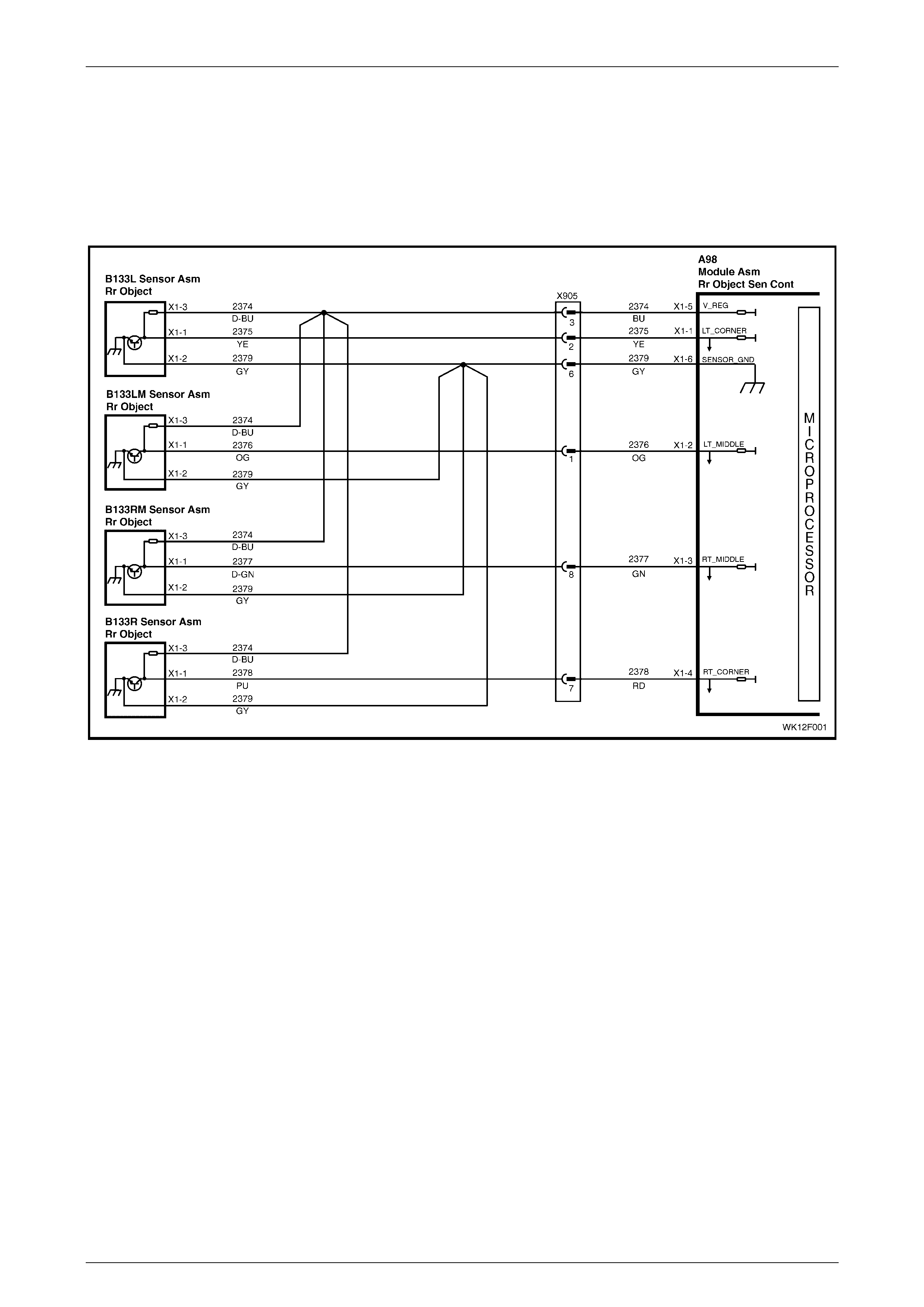
2.1 Sensor Circuit Test
Figure 12F – 1
NOTE
Prior to performing this test, ensure the ground
and power circuits function correctly and nothing
is connected into the trailer socket.
• For connector details refer to
4.3 CONNECTOR VIEWS, Section 12F
REVERSE PARKING AID in the MY 2003 VY
and V2 Series Service Information.
• For connector and ground point locations
refer to Section 12P WIRING DIAGRAMS.

Reverse Park ing Aid Page 12F–5
01–DEC–2002 Page 12F–5
Step Action Yes No
1 1 Perform a self-diagnosis test, refer to 3.2 SELF-DIAGNOSIS,
Section 12F REVERSE PARKING AID in the MY 2003 VY and
V2 Series Service Information. Does the test indicate a fault?
Go to 2. System serviceable.
2 1 Switch the ignition on and select reverse gear.
2 Back-probe the control module connector A98 pin 5 circuit 2374
(blue wire) with a voltmeter. Is there approximately +8V present?
Go to 3. Replace control
module, refer to 2.1
REAR OBJECT
SENSOR
CONTROL
MODULE, Section
12F REVERSE
PARKING AID in
the MY 2003 VY
and V2 Series
Service Information.
3 1 Back-probe the control module connector A98 pin 6 circuit 2379
(grey wire). Does continuity exist between pin 6 and ground? Go to 4. Replace control
module, refer to 2.1
REAR OBJECT
SENSOR
CONTROL
MODULE, Section
12F REVERSE
PARKING AID in
the MY 2003 VY
and V2 Series
Service Information.
4 1 Are the following connectors secure?
• A98
• X905
• B133 L
• B133 LM
• B133 RM
• B133 R
Go to 5. Secure connector.
5 1 Disconnect the sensor connectors B133 and the control module
connector A98. Does continuity exist on circuits 2374 between
pin 3 on each sensor connector and pin 5 on the control module
connector?
Go to 6. Repair any faulty
circuit.
6 1 Disconnect the left sensor connector B133 and the control
module connector A98. Does continuity exist on circuit 2375
between pin 1 on the left sensor connector and pin 1 on the
control modu le con nect o r?
2 Disconnect the left middle sensor connector B133 and the
control module connector A98. Does continuity exist on circuit
2376 between pin 1 on the left middle sens or connector and pin
2 on the control module con ne ctor?
3 Disconnect the right middle sensor connector B133 and the
control module connector A98. Does continuity exist on circuit
2377 between pin 1 on the right middle sensor connector and
pin 3 on the control module connector?
4 Disconnect the right sensor connector B133 and the control
module connector A98. Does continuity exist on circuit 2378
between pin 1 on the right sensor connector and pin 4 on the
control modu le con nect o r?
Go to 7. Repair any faulty
circuit.

Reverse Park ing Aid Page 12F–6
01–DEC–2002 Page 12F–6
Step Action Yes No
7 1 Disconnect the sensor connectors B133 and the control module
connector A98. Does continuity exist on circuits 2379 between
pin 2 on each sensor connector and pin 6 on the control module
connector?
Replace faulty
sensor, refer 2.4
REAR OBJECT
SENSOR
ASSEMBLY,
Section 12F
REVERSE
PARKING AID in
the MY 2003 VY
and V2 Series
Service Information.
Repair any faulty
circuit.
W HEN ALL DIAGNOSIS AND REPAIRS ARE COMPLETE, VERIFY CORRECT OPERATION.