
Cellular Phone Page 12G–1
Page 12G–1
Section 12G
Cellular Phone
ATTENTION
Before performing any Service Operation or other procedure described in this Section, refer to Section 00
Warnings, Cautions and Notes for correct workshop practices with regard to safety and/or property damage.
1 General Information............................................................................................................................... 2
2 Service Operations................................................................................................................................3
2.1 Coupling Box Assembly........................................................................................................................................3
Remove ...................................................................................................................................................................3
Reinstall ..................................................................................................................................................................3
2.2 Cellular Phone Antenna Lead................................................................................................................................4
Remove ...................................................................................................................................................................4
Reinstallation..........................................................................................................................................................5
3 Torque Wrench Specifications............................................................................................................. 6

Cellular Phone Page 12G–2
Page 12G–2
1 General Information
With the following exceptions, MY 2004 WK Series Cellular Phone information carries over from MY 2003 VY Series
vehicles. For information not contained within this Section, refer to Section 12G Cellular Phone in the MY 2003 VY and
V2 Series Service Information.
• Coupling box assembly
• Antenna lead
The antenna coupling box assembly (internal) and antenna lead for the cellular phone are installed as standard fitment to
these vehicles, ready for the installation of a cellular phone. The coiled-up antenna lead, which is not fitted with a
connector, is located behind the left instrument panel lower trim plate assembly.
NOTE
The antenna mast and base assembly (external)
are supplied as a kit with the vehicle, together
with installation instructions.
Cellular Phone Page 12G–3
Page 12G–3
2 Service Operations
2.1 Coupling Box Assembly
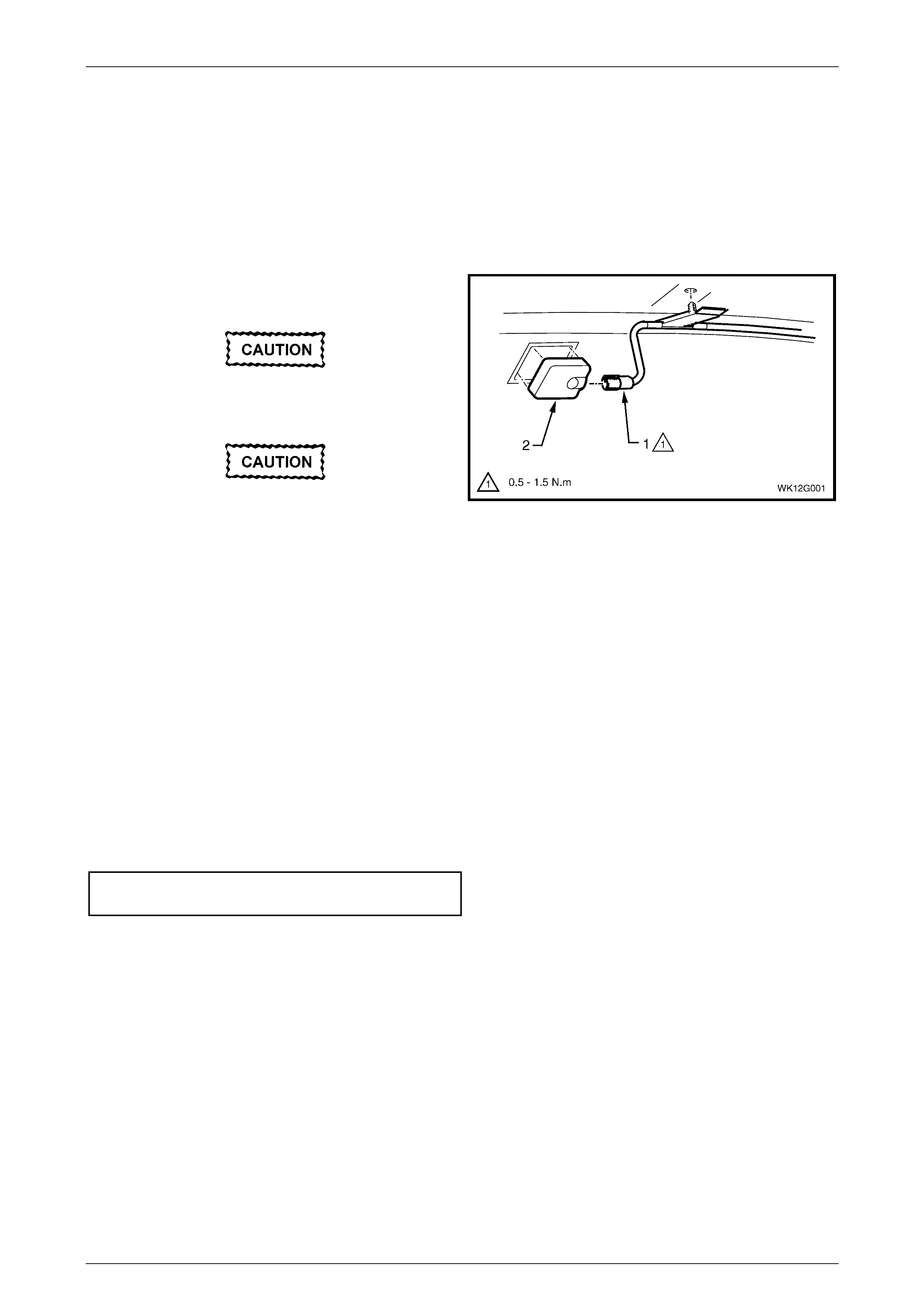
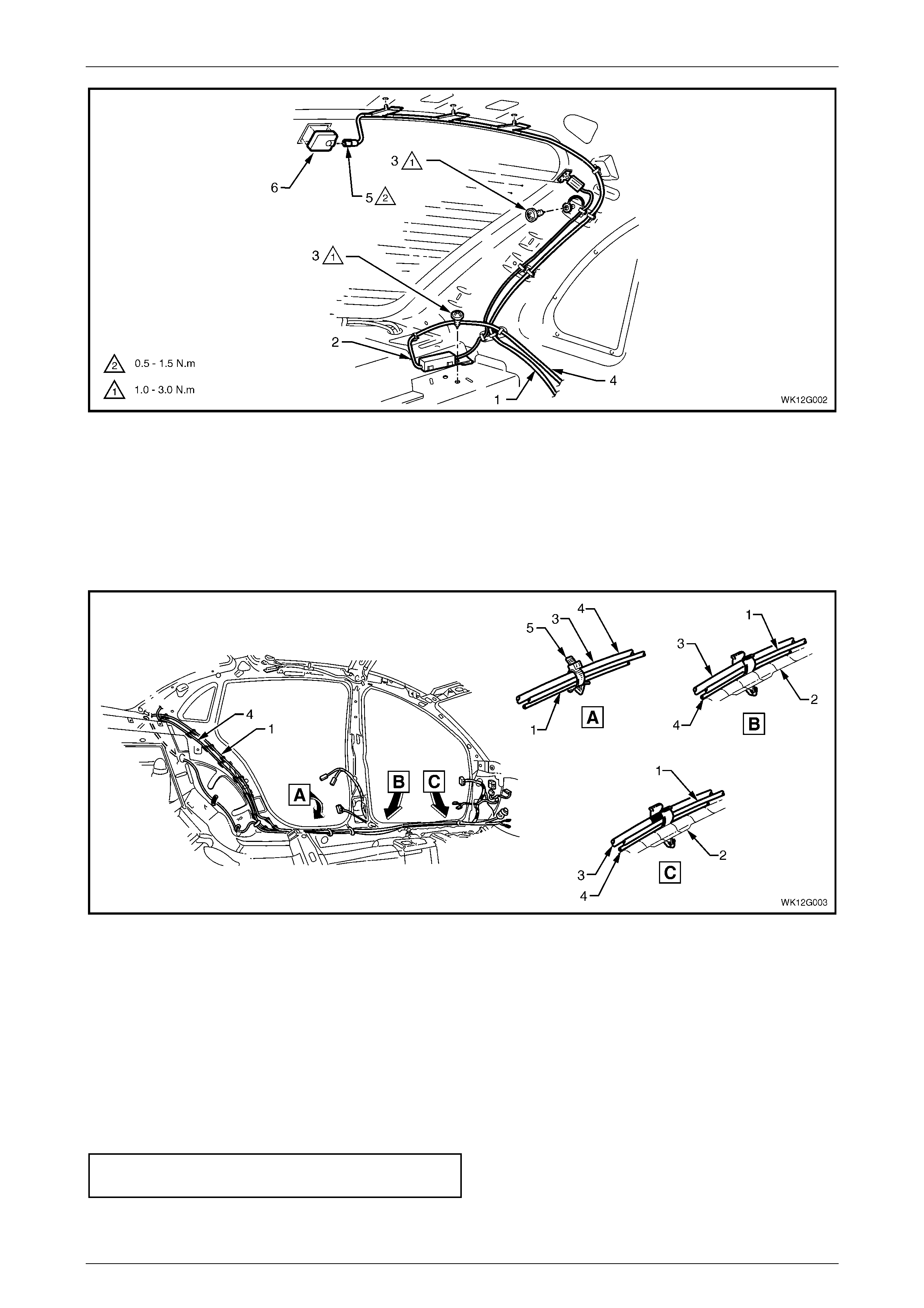
The coupling box is located in the centre at the top of the rear window assembly. Refer to Figure 12G – 3.
Remove
1 Unscrew the cellular phone antenna (1) from the
coupling box assembly (2).
Take care to avoid damage to the diversity
antenna.
Do not use a metallic instrument to remove
the coupling box as this will damage the
window.
2 Remove the cellular phone antenna coupling box
assembly by pulling the coupling box from the window.
If necessary, use a flat-bladed instrument (e.g. spatula
or scraper) to prise the coupling box from the window.
3 Discard the coupling box.
4 Remove any residue adhesive material from the
window and the coupling box.
Figure 12G – 1
Reinstall
1 Wipe the window using isopropyl alcohol and ensure that all adhesive residue is removed.
2 Remove the backing from the new coupling box, align the coupling box with the guide marks on the window,
ensuring that the cable connector is positioned to the side indicated by the guide marks, and press the coupling
box firmly into position on the window.
3 Connect the cellular phone antenna lead to the coupling box assembly.
Cellular phone antenna connector
torque specification ....................................0.5 - 1.5 N.m
Cellular Phone Page 12G–4
Page 12G–4
2.2 Cellular Phone Antenna Lead
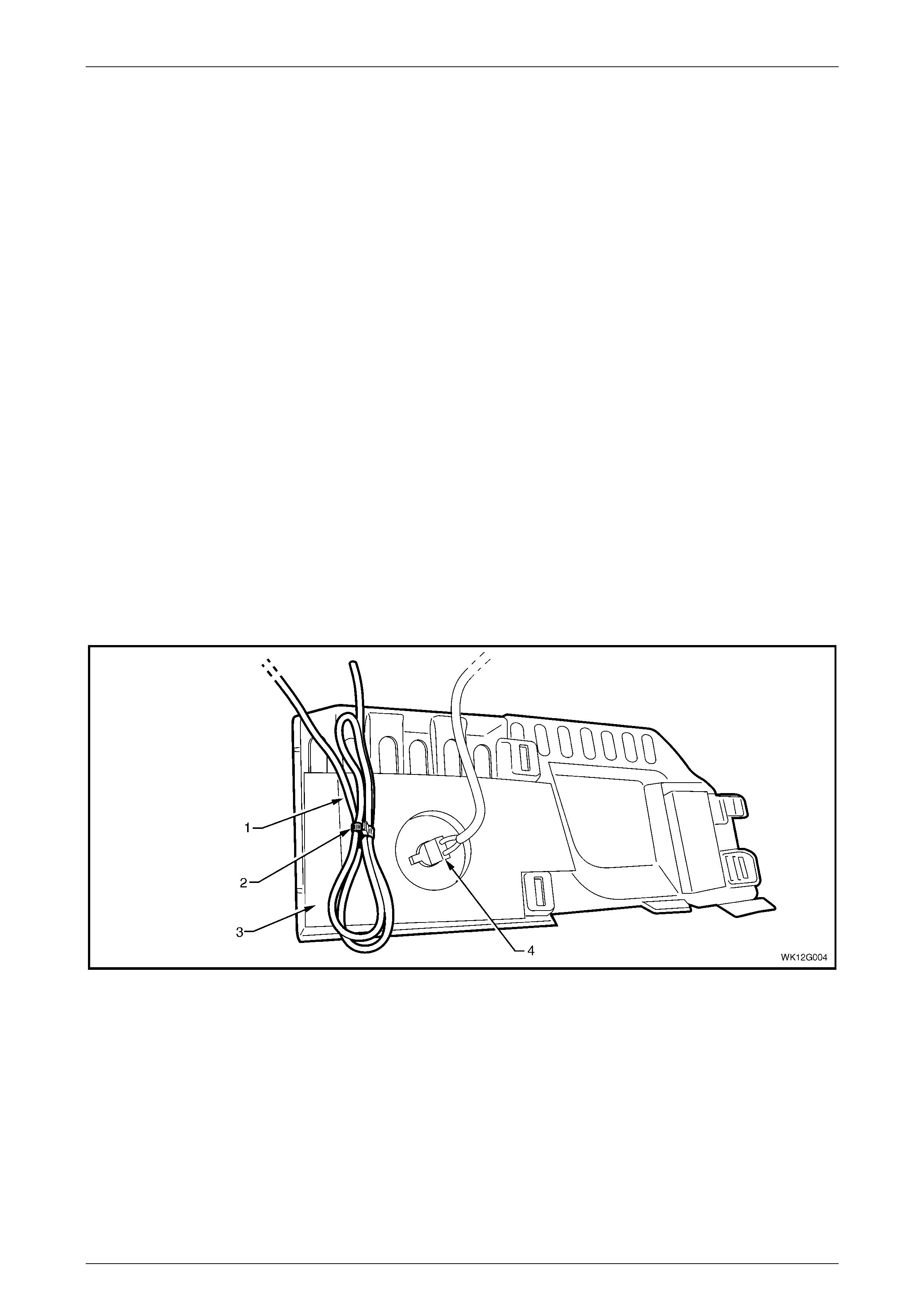
Refer to Figure 12G – 2, Figure 12G – 3 and Figure 12G – 4 for the following.
The cellular phone antenna lead is connected to the coupling box assembly and is routed to the left instrument panel
lower trim plate assembly down the left-hand side of the vehicle. At the left instrument panel lower trim plate assembly,
the coiled-up cellular phone antenna lead, which is not fitted with a connector, is clipped to the rear of the left instrument
panel lower trim plate assembly.
NOTE
If access is required to the cellular phone
antenna lead when installing a cellular phone,
only perform steps 1 and 2 in the procedures
below.
Remove
1 Remove the left instrument panel lower trim plate assembly, refer to Section 1A3 Instrument Panel and Console.
2 Remove the antenna lead from the retaining clip.
3 Remove the left hinge pillar trim assembly, refer to Section 1A8 Headlining and Interior Trim.
4 Remove the left side sill trim, refer to Section 1A8 Headlining and Interior Trim.
5 Remove the rear window trim panel, refer to Section 1A8 Headlining and Interior Trim
6 Remove the left body lock pillar garnish, refer to Section 1A8 Headlining and Interior Trim.
7 Remove the left body lock pillar lower trim, refer to Section 1A8 Headlining and Interior Trim.
8 Remove the left quarter inner rear side carpet, refer to Section 1A8 Headlining and Interior Trim.
Figure 12G – 2
Legend
1 Cellular Phone Antenna Lead
2 Retaining Clip 3 Left Instrum ent Panel Lower Trim Plate Assembly
4 Stepwell Lamp
Cellular Phone Page 12G–5
Page 12G–5
Figure 12G – 3
Legend
1 Cellular Phone Antenna Lead
2 Diversity Antenna
3 Screw
4 Diversit y Antenna Lead
5 Cellular Phone Antenna Lead Connector
6 Cellular Phone Coupl i ng Box Connector
Figure 12G – 4
Legend
1 Diversity Antenna Lead
2 Body Wiring Harness
3 Navigation System Harness
4 Cellular Phone Antenna Lead
5 Strap
Reinstallation
1. Installation is the reverse of the removal procedure ensuring that the fasteners are tightened to the correct torque
specification.
Cellular phone antenna connector
torque specification ....................................0.5 - 1.5 N.m

Cellular Phone Page 12G–6
Page 12G–6
3 Torque Wrench Specifications
Antenna Connector.......................................................................0.5 – 1.5 N.m