
Rear-view Mirrors Page 12H–1
Page 12H–1
Section 12H
Rear-view Mirrors
ATTENTION
Before performing any Service Operation or other procedure described in this Section, refer to Section 00
CAUTIONS AND NOTES for correct workshop practices with regard to safety and/or property damage.
1 General Information............................................................................................................................... 2
1.1 Electro-chromatic Interior Rear-v iew Mirror ........................................................................................................2
2 Service Operations................................................................................................................................3
2.1 Electro-chromatic Interior Rear-v iew Mirror ........................................................................................................3
Remove ...................................................................................................................................................................3
Reinstall ..................................................................................................................................................................3
2.2 Heated Exterior Mirror Glass.................................................................................................................................4
Remove ...................................................................................................................................................................4
Heater Element Test...............................................................................................................................................5
Reinstall ..................................................................................................................................................................5
3. Electro-chromatic Interior Rear-view Mirror Diagnosis..................................................................... 6
3.1 Functional Check ...................................................................................................................................................6
3.2 Electro-chromatic Interior Rear-view Mirror Circuit Diagram and Connectors.................................................7
3.3 Electro-chromatic Interior Rear-view Mirror Diagnostic Chart...........................................................................9
Test Description.....................................................................................................................................................9
Notes .......................................................................................................................................................................9
Diagnostic Chart.....................................................................................................................................................9

Rear-view Mirrors Page 12H–2
Page 12H–2
1 General Information
With the following exceptions, MY 2004 WK Series rear-view mirror information carries over from MY 2003 VY Series
Models. For all rear-view mirror information not contained in this Section, refer to Section 12H, Rear-view Mirrors in the
MY 2003 VY and V2 Series Service Information.
• On all Level 5 Models, the heated exterior rear-view mirrors integrate with the memory seat and mirror system. For
all information regarding this feature, refer to Section 1A7, Seat Assemblies in this Service Information.
• All Level 5 Models are fitted with unique heated type exterior rear-view mirrors.
• An electro-chromatic interior rear-view mirror is fitted as standard equipment to all left-hand drive Level 5 Models,
which, when set to automatic, electronically change the colour of the mirror glass to reduce the reflection of
headlamps from a following vehicle.
• The Telematics (Holden Assist) system is fitted as standard equipment on right-hand drive Level 5 Models, and as
optional equipment on all right-hand drive Level 4 Models. Those vehicles fitted with the Telematics system are
fitted with a unique interior rear-view mirror. For all information regarding the interior rear-view mirror fitted with the
Telematics system, refer to Section 12K, Telematics in the MY 2003 VY Series and V2 Series Service Information.
1.1 Electro-chromatic Interior Rear-view
Mirror
An electro-chromatic interior rear-view mirror is fitted to all left-hand drive Level 5 Models. The mirror features an
electronically controlled mirror cell which changes colour in response to an applied electrical voltage. This allows
automatic darkening of the mirror during night driving when headlamps from a following vehicle shine on an integrated
light sensor on the front of the mirror assembly. A second sensor is incorporated at the rear of the mirror assembly which
detects low ambient light (sun sensor). This second sensor ensures that this feature only works at night time.
Incorporated on the bottom of the mirror assembly is an auto (on) / off switch. When the switch is switched from auto to
off, the mirror reverts to a standard ‘day driving’ mirror.
When the mirror is switched to the auto position and reverse gear is selected, the mirror will switch to the day setting,
regardless of the ambient light level.

Rear-view Mirrors Page 12H–3
28-FEB-2003 Page 12H–3
2 Service Operations
2.1 Electro-chromatic Interior Rear-view
Mirror
LT Section No. – 14-025
Remove
1 Remove mirror wiring harness cover (1) by sliding
cover upwards slightly (direction A) and pull cover
downwards (direction B).
Figure 12H-1
2 Disconnect the interior mirror wiring harness
connector (1).
Figure 12H-2
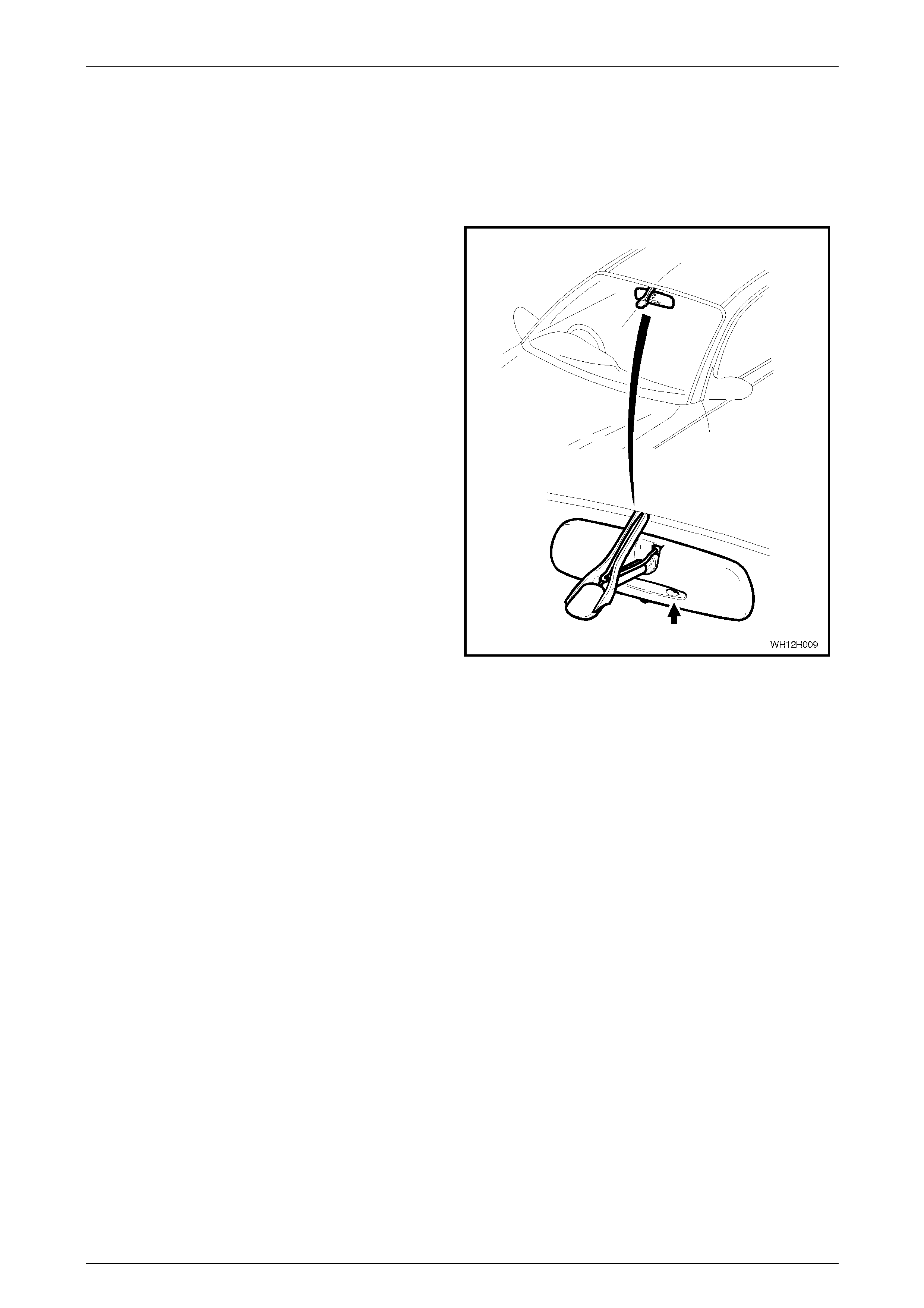
3 Disengage the interior mirror from the windscreen
mounted boss by grasping the mirror lens firmly by
hand and peeling the mirr or as sembly dow nwards
towards the lower edge of the windscreen, and
remove the internal rear-view mirror.
Figure 12H-3
Reinstall
The reinstallation procedure for the electro-chromatic interior rear-view mirror is the reverse of the removal procedure,
noting the following:
• When installing the mirror onto the boss on the windscreen, slide the mirror assembly from the top of the boss
downwards, ensuring that it is pushed down fully. An audible click should occur as the mirror assembly locks into
position.
Rear-view Mirrors Page 12H–4
Page 12H–4
2.2 Heated Exterior Mirror Glass
LT Section No. – 10-400
Remove
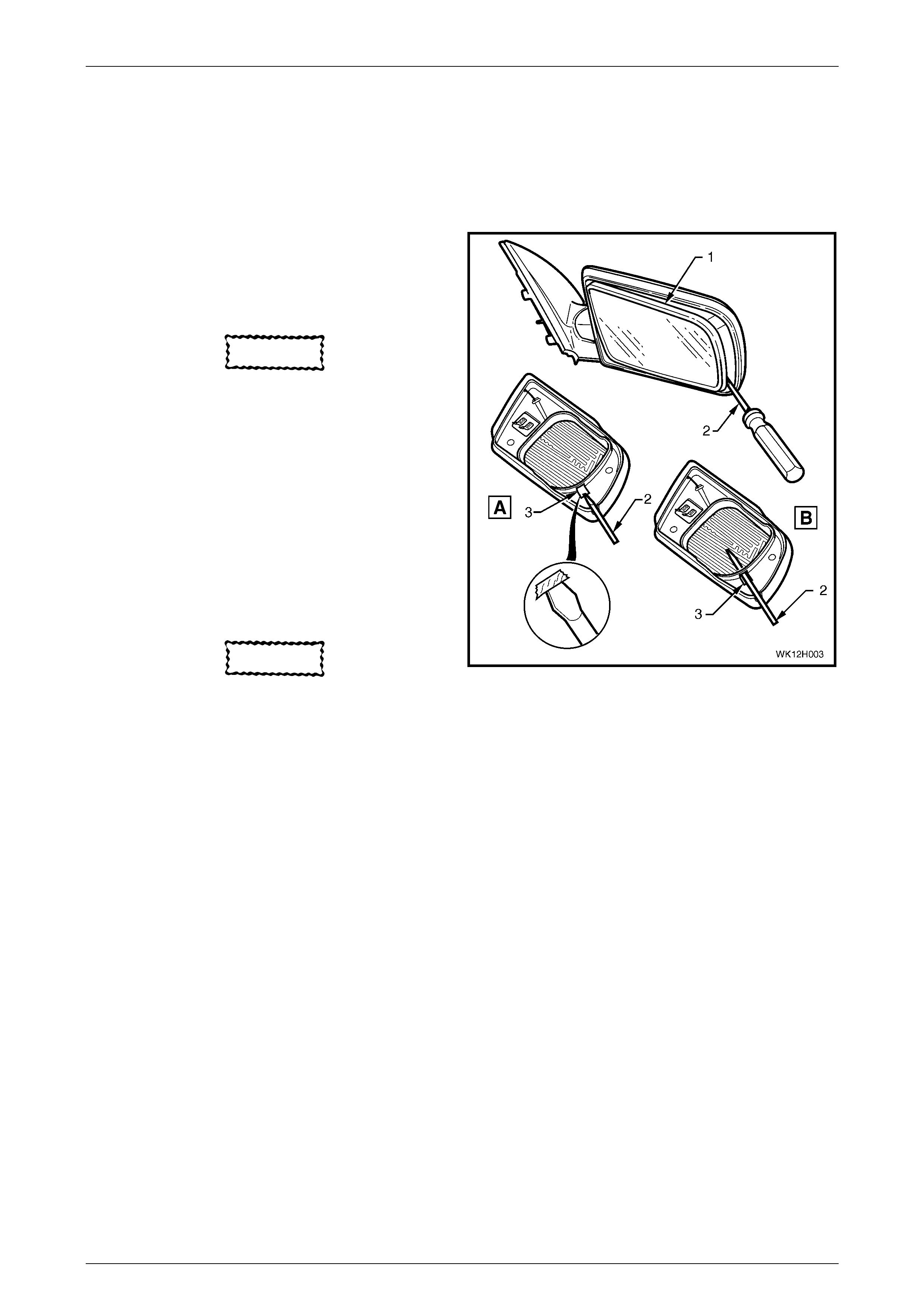
1 Adjust the mirror glass (1) so it is in the fully UP and
fully IN position.
2 Wrap the end of a flat tip screw driver (2) with tape or
a clean shop rag.
CAUTION
The heater element for the heated type
exterior rear-view mirror is fitted to the
rear of the mirror glass and is susceptible
to damage during mirror glass removal.
Extreme care must be taken while
removing the mirror glass from a heated
type rear-view mirror.
3 Insert the screwdriver into the slot (3) on the inside of
the mirror glass, refer to View A.
4 Gently lever the mirror glass away from the motor
assembly while slowly inserting the screwdriver further
into the assembly, refer to View B.
CAUTION
The heated type exterior rear-view mirror
has two heater wires attached to the rear
of the mirror glass. When disconnecting
the two heater wires, the male terminals
should be held against the heater element
or damage to the element may occur.
5 Mark one of the two heater wires to assist during
reassembly, then disconnect both heater wires from
the heater element on the rear of the mirror glass.
6 Remove the mirror glass from the motor assembly.
Figure 12H-4
Rear-view Mirrors Page 12H–5
Page 12H–5
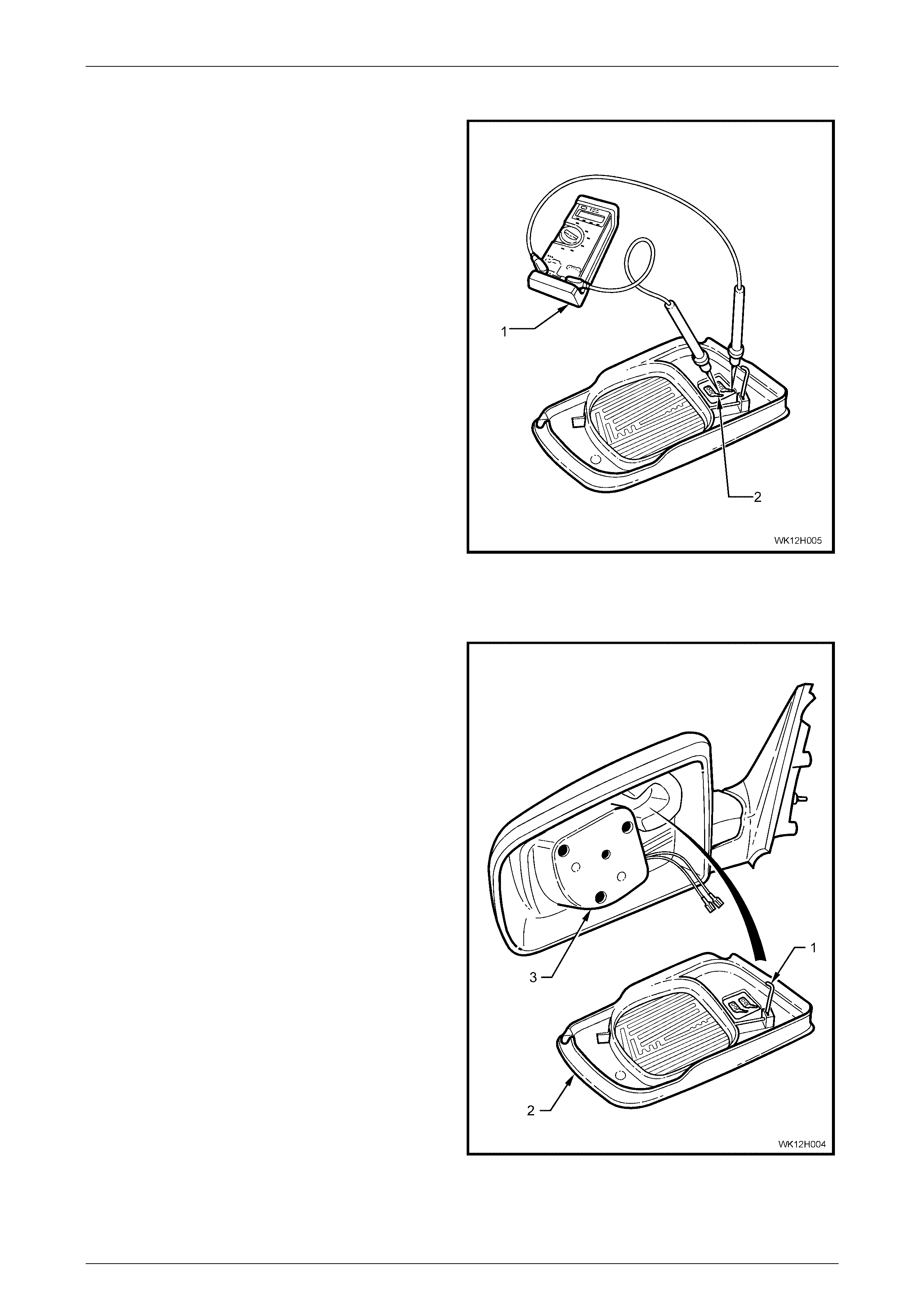
Heater Element Test
1 Using a suitable digital multi-meter, measure the
resistance between the two heater element spade
terminals.
2 The resistance sho uld be 15 ± 2 Ω. If the resistance of
the heater element is outside this range, replace the
glass.
Figure 12H-5
Reinstall
The reinstallation of the heated mirror glass is the reverse of
the removal procedure noting the following:
1 Ensure the anti-vibration spring rod (1) is at a right
angle to the mirror glass (2) and that it aligns with the
correspondin g aperture in the mirror housin g.
2 Support the mirror housing and push the mirror glass
squarely onto the motor assembly (3) until it is firmly
seated.
Figure 12H-6
Rear-view Mirrors Page 12H–4
28-FEB-2003 Page 12H–4
3. Electro-chromatic Interior Rear-
view M irror Diagnosis
3.1 Functional Check
The following procedure should be used to check if the
electro-chromatic interior rear-view mirror is functioning
correctly:
1 With mirror instal led, cover the ambient lig ht sen sor at
the rear of the mirror (forward facing), using a piece of
black electrical tape.
2 Turn ignition switch to the ‘ON’ position.
3 Turn mirror switch to the ‘AUTO’ position.
4 Observe that the ‘GREEN’ LED in mirror is
illuminated.
5 Shine a beam of light (torch) into the front light sensor
(rearward facing) and ensure that the mirror darkens.
NOTE
The front light sensor is located adjacent to the
green LED, to the left of the auto / off switch.
6 With the ignition on, select reverse gear, mirror
should return to full reflectance in 5 - 10 seconds.
7 Repeat Step 5, then turn the mirror off (LED off) and
turn the igniti on switch to ‘OFF’ position. Mirror should
again return to full reflectance 5 - 10 seconds.
NOTE
If the mirror does not function according to the
above procedures, remove the mirror, as per
the procedure detailed in this Section and
proceed to 3.3 Electro-chromatic Interior Rear-
view Mirror Diagnostic Chart in this Section.
Figure 12H-4
Rear-view Mirrors Page 12H–5
28-FEB-2003 Page 12H–5
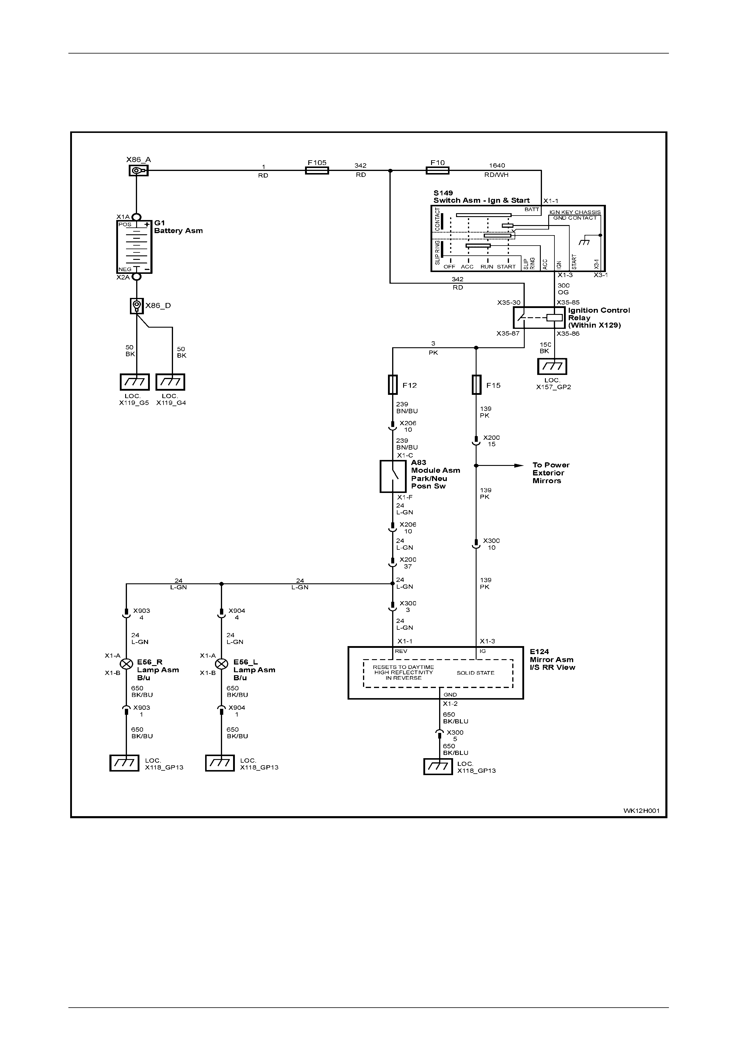
3.2 Electro-chromatic Interior Rear-view
Mirror Circuit Diagram and Connectors
Figure 12H-5
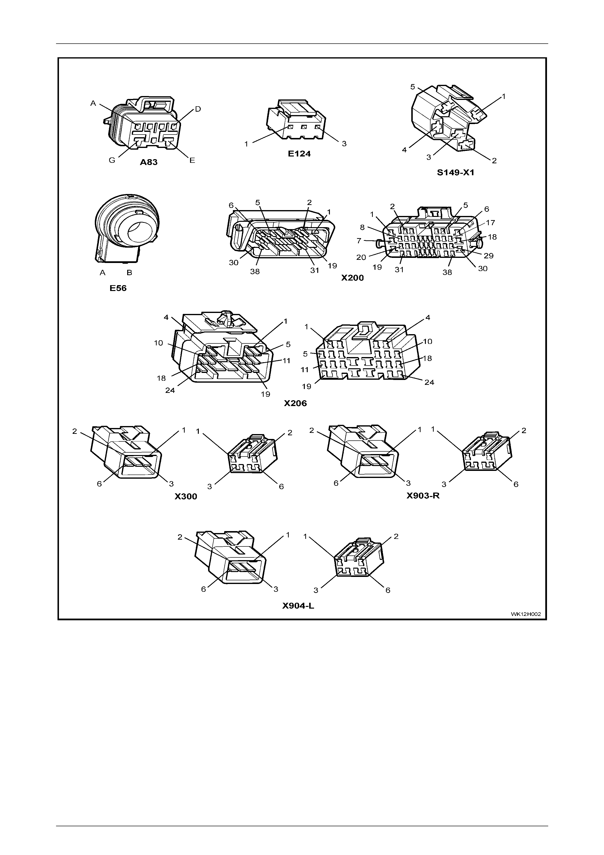
Rear-view Mirrors Page 12H–6
28-FEB-2003 Page 12H–6
Figure 12H-6
Rear-view Mirrors Page 12H–7
28-FEB-2003 Page 12H–7
3.3 Electro-chromatic Interior Rear-view
Mirror Diagnostic Chart
Test Description
The numbers below refer to step numbers in the diagnostic chart for the electro-chromatic interior rear-view mirror.
1 Ensures the Functional Check has been performed.
2 Determines if the functionality of the mirror is correct.
3 Determines if the functionality of the mirror is correct.
4 Checks circuits 139 and 650 for power and earth at electro-chromatic interior rear-view mirror connector X300.
5 Checks circuit 139 for open or short to earth.
6 Checks circuit 650 for open.
7 Checks earth connection at ground point GP13 (right-hand tail lamp stud).
8 Checks integrity of back-up lamp circuits 24 and 239 (including operation of back-up lamp switch).
Notes
NOTE
Refer to Section 12P, Wiring Diagrams in the
MY2003 VY Series and V2 Series Service
Information for procedures on checking wiring
faults.
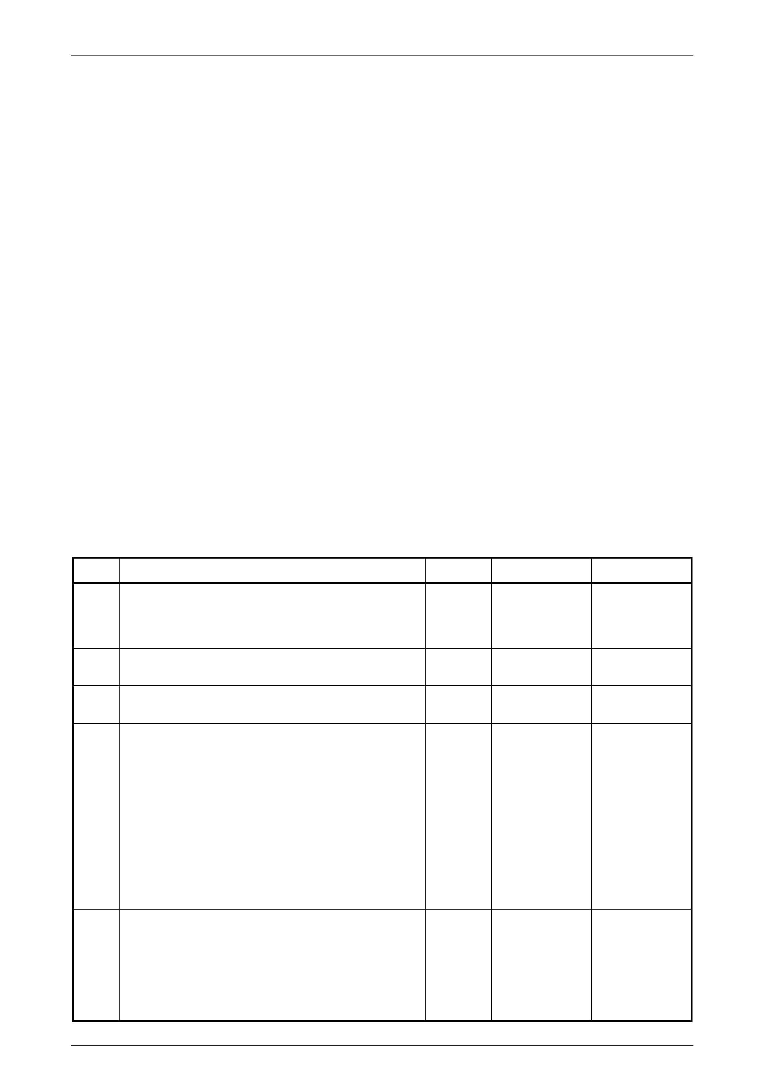
Diagnostic Chart
STEP ACTION VALUE YES NO
1 Has the electro-chromatic interior rear-view mirror
Functional Check been performed? Go to Step 2. Go to
3.1 Functional
Check in this
Section.
2 In Step 5 of the Functional Check, did mirror change
colour (darken)? Go to Step 3. Go to Step 4.
3 In Step 6 of the Functional Check, did mirror return to full
reflectance when reverse gear was selected? Mirror OK Go to Step 8.
4 Remove electro-chromatic interior rear-view mirror, refer
2.1 Electro-chro matic Interior Rear-view Mirror in this
Section.
Disconnect the electro-chromatic interior rear-view mirror
connector (X300).
Measure voltage between connector X300 circuit 139
(Pink wire) and circuit 650 (Black/Blue wire). Refer to
Notes in this Section.
Turn ignition ON.
Is voltage as specified?
Battery + Go to Step 5. Replace electro-
chromatic
interior rear-view
mirror assembly,
refer 2.1 Electro-
chromatic
Interior Rear-
view Mirror in
this Section.
5 With the electro-chromatic interior rear-view mirror
connector (X300) disconnected, measure voltage
between connector X300 circuit 139 (Pink wire) and a
known good earth. Refer to Notes in this Section.
Turn ignition ON.
Is voltage as specified?
Battery + Go to Step 6. Repair open or
short to earth in
circuit 139 as
necessary
(including fuse
F15). Recheck
and verify repair.

Rear-view Mirrors Page 12H–8
28-FEB-2003 Page 12H–8
6 Turn ignition OFF.
With electro-chromatic interior rear-view mirror connector
(X300) disconnected, check for continuity between
connector X300, circuit 650 (Black/Blue wire) and earth
at ground point GP13 (right-hand tail lamp stud). Refer to
Notes in this Section.
Does continu ity ex ist?
Go to Step 7. Repair open in
circuit 650 as
necessary.
Recheck and
verify repair.
7 Turn ignition OFF.
Check for continuity between ground point GP13 (right-
hand tail lamp stud) and a known good earth. Refer to
Notes in this Section
Does continu ity ex ist?
Replace electro-
chromatic
interior rear-view
mirror assembly,
refer 2.1 Electro-
chromatic
Interior Rear-
view Mirror in
this Section.
Repair earth as
necessary.
Recheck and
verify repair.
8 Remove electro-chromatic interior rear-view mirror, refer
2.1 Electro-chro matic Interior Rear-view Mirror in this
Section.
Disconnect electro-chromatic interior rear-view mirror
connector (X300).
Measure voltage between connector X300 circuit 24
(Light Green wire) and a known good earth. Refer to
Notes in this Section.
Turn ignition ON.
Select reverse gear.
Does voltage change from 0 volts to battery + volts when
reverse gear is selected?
Replace electro-
chromatic
interior rear-view
mirror assembly,
refer 2.1 Electro-
chromatic
Interior Rear-
view Mirror in
this Section.
Repair back-up
lamp circuits 24
and 239 as
necessary
(including
operation of
back-up lamp
switch, refer to
Section 12B
Lighting System
in this Service
Information).
Recheck and
verify repair.