
Multi Function Display Page 12I–1
Page 12I–1
Section 12I
Multi Function Display
ATTENTION
Before performing any Service Operation or other procedure described in this Section, refer to Section 00
Warnings, Cautions and Notes for correct workshop practices w i th regard to safety and/or property damage.
1 General Information............................................................................................................................... 3
1.1 General Description ...............................................................................................................................................3
MFD Installation......................................................................................................................................................3
MFD Components...................................................................................................................................................4
MFD Electrical Connection....................................................................................................................................5
Connector X1......................................................................................................................................................5
MFD Electrical Communication.............................................................................................................................6
MFD Communication with Occupant Climate Control (OCC) Module.................................................................6
MFD Communication with Audio Head Unit (AHU).............................................................................................6
1.2 System Operation...................................................................................................................................................7
MFD Screen Displays.............................................................................................................................................7
Time / Date Display ............................................................................................................................................7
Radio Operation..................................................................................................................................................8
Heating Ventilation and Air Conditioning (HVAC) System Operation..................................................................9
Rear Remote Control........................................................................................................................................10
Fixed Icons .......................................................................................................................................................11
Setting MFD Time / Date ......................................................................................................................................12
Procedure – Normal..........................................................................................................................................12
Procedure – AHU Removed .............................................................................................................................12
MFD Illumination ..................................................................................................................................................12
Illumination Adjustment.....................................................................................................................................12
Illumination Adjustment Signal Path .................................................................................................................12
2 Service Operations.............................................................................................................................. 13
2.1 Multi Function Display.........................................................................................................................................13
Remove .................................................................................................................................................................13
Reinstall ................................................................................................................................................................16
3 Diagnosis.............................................................................................................................................. 17
3.1 MFD Diagnostics..................................................................................................................................................17
Diagnostic Trouble Codes...................................................................................................................................17
3.2 Connecting TECH 2 For System Diagnosis.......................................................................................................18
3.3 TECH 2 Test Modes and Displays.......................................................................................................................19
Main Menu.............................................................................................................................................................19
Model Year .......................................................................................................................................................20
Vehicle Identification Menu...............................................................................................................................20
System Selection Menu....................................................................................................................................20
Multi Function Display Selection.......................................................................................................................21
Body Menu............................................................................................................................................................22
F0: Normal Mode ..................................................................................................................................................22
Normal Mode Data List.....................................................................................................................................22
F1: Diagnostic Trouble Codes.............................................................................................................................23
Read Current DTC Information.........................................................................................................................23
Diagnostic Trouble Codes ................................................................................................................................23
Techline

Multi Function Display Page 12I–2
Page 12I–2
3.4 Data Display..........................................................................................................................................................24
F0: Data List..........................................................................................................................................................24
Data Display List...............................................................................................................................................24
F1: System Identification.....................................................................................................................................25
3.5 Snapshot...............................................................................................................................................................26
3.6 Miscellan eous Tests ............................................................................................................ ................................27
F0: Park Lamp Input.............................................................................................................................................27
F1: All Segments..................................................................................................................................................28
F2: Chequered Pattern.........................................................................................................................................29
HVAC LCD Display Test...................................................................................................................................31
3.7 Program.................................................................................................................................................................32
F0: Program Code Index ..................................................................................................................................32
3.8 Multi Function Display Diagnostic Procedures.................................................................................................34
General Diagnostics.............................................................................................................................................34
MFD Diagnostic Circuit Check Diagnostic Chart...............................................................................................35
MFD No Power......................................................................................................................................................36
MFD No Power Diagnostic Chart......................................................................................................................36
No Illumination or No Dimming Control.............................................................................................................37
No Illumination or No Dimming Control Diagnostic Chart .................................................................................37
No Audio Information Displayed.........................................................................................................................38
No Radio Information Displayed Diagnostic Chart............................................................................................38
DTC – No Serial Data From Audio System.........................................................................................................40
No Serial Data From Audio System Diagnostic Chart.......................................................................................40
DTC – No CAN Communication From OCC System..........................................................................................42
No CAN Communication From OCC System Diagnostic Table........................................................................ 42
DTC – EEPROM Error...........................................................................................................................................44
4 Wiring Diagrams .................................................................................................................................. 45
Connectors (A14 – S125).....................................................................................................................................46
Connectors continued (X40 – X129)...................................................................................................................47
Wiring diagram: Multi Function Display.............................................................................................................48
5 Torque Wrench Specifications........................................................................................................... 49
6 Special Tools........................................................................................................................................ 50
Multi Function Display Page 12I–3
Page 12I–3
1 General Information
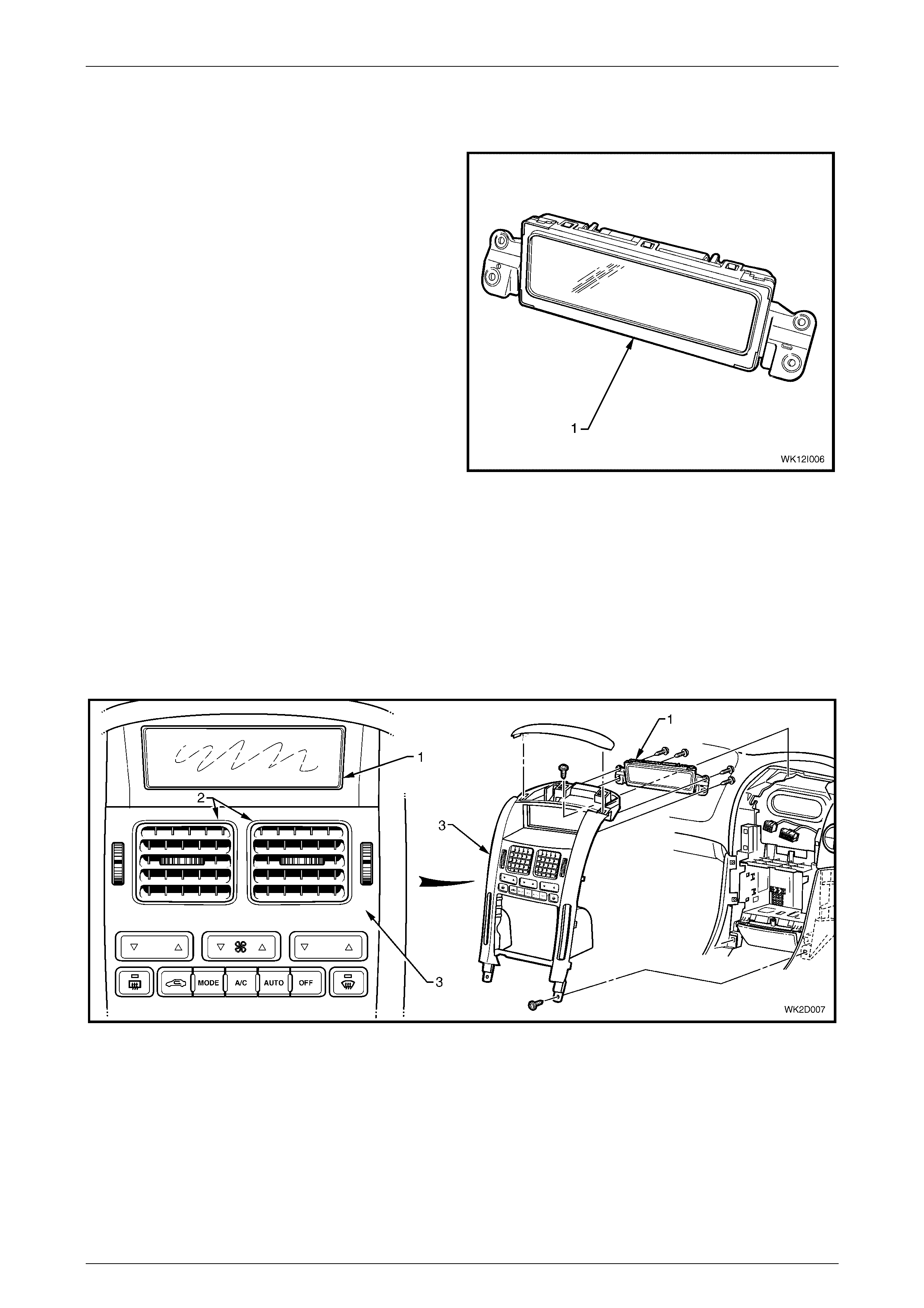
A Multi Function Display (MFD) module (1) is fitted to all
LHD Level 2 to 5 and RHD Level 4 and 5 MY 2004 WK
Series models. For further information relating to the MFD
can be found in the following references:
• Section 12D Entertainment System
• Section 2D HVAC Occupant Climate Control
(Auto A/C) – Description and Operation
• Vehicle Owner's Handbook and Audio supplement
Figure 12I – 1
1.1 General Description
The MFD has a liquid crystal display that is used to convey to the vehicle occupants the active functions and settings of
the Audio Head Unit (AHU) and Occupant Climate Control (Auto A/C).
MFD Installation
The MFD (1) is located above the face level centre vents (2) and is attached to the back of the instrument panel centre
trim assembly (3) at four points.
Figure 12I – 2

Multi Function Display Page 12I–4
Page 12I–4
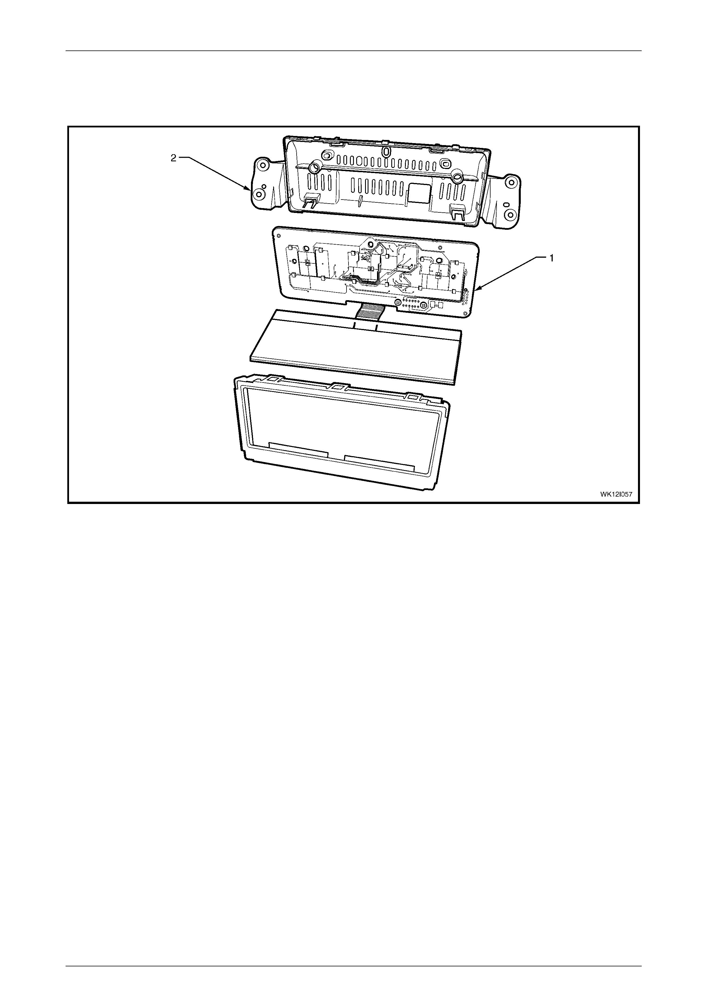
MFD Components
The MFD module is designed for ease of assembly and no screws are used in its construction aside from those used to
install the electrical connector to the rear of the circuit board. The LCD screen carrier and rear housing of the module are
constructed of plastic. Contained within the module is a printed circuit board, which is installed into the rear housing and
retained by locking tabs at four locations. Information from the circuit board is transferred to the LCD screen through a
ribbon cable. A 12-pin electrical connector is secured by screws to the rear of the circuit board. The MFD harness
attaches directly to the circuit board through an aperture in the module’s rear housing. The LCD screen and diffuser are
mounted to the front of the LCD screen carrier. The carrier and its contents are installed to the front of the rear housing
and retained by the metallic LCD frame, which clips over the rear housing at six locations. The complete module is
mounted to the rear of the instrument centre trim at two flanges moulded either side of the rear housing and is retained
by four screws.
There are no replaceable bulbs contained within the MFD module. LEDs are used to provide illumination where
necessary. The MFD has no serviceable items. If any component fails to function, the module must be replaced.
Figure 12I – 3
Legend
1 LCD Frame 5 Ribbon Cable
2 LCD Diffuser 6 Circuit Board
3 LCD Screen Carrier 7 Rear Housing
4 LCD Screen
Multi Function Display Page 12I–5
Page 12I–5
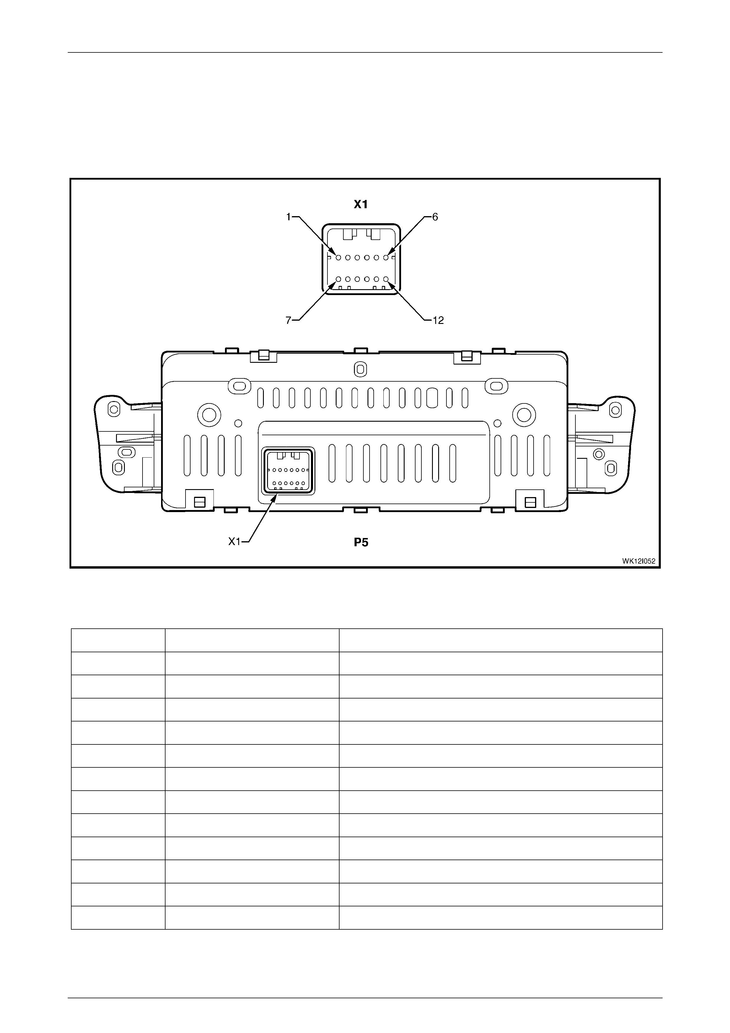
MFD Electrical Connection
One electrical connector is located to the rear of the MFD module. In accordance with the Integrated Vehicle Electrical
Design (IVED) standard as applied to MY 2004 WK Series vehicles, the module is designated as P5 and the connector is
designated as Connector X1. The connector is screw mounted to the rear of the printed circuit board.
Figure 12I – 4 provides a view of the connector terminal assignments and the tables following it provide information on
their function.
Figure 12I – 4
Connector X1
Pin Number Wire Colour Function
X1-1 Yellow OCC module – (CAN_HI)
X1-2 – Not connected
X1-3 Brown / White Park lamps control relay – Illumination Dimming
X1-4 Blue / White Serial data line
X1-5 – Not connected
X1-6 – Not connected
X1-7 Brown OCC module – (CAN_LO)
X1-8 – Not connected
X1-9 – Not connected
X1-10 Black / Yellow Ground (X157)
X1-11 Orange / Yellow Fuse F21 – Power from battery
X1-12 Yellow Fuse F16 – Accessory Control Relay

Multi Function Display Page 12I–6
Page 12I–6
MFD Electrical Communication
MFD Communication with Occupant Climate Control (OCC) Module
The MFD is connected directly to the OCC control module by two wires (Circuit 5169, CAN_HI and Circuit 5170,
CAN_LO). The communication principle used between these two modules is a dedicated CAN (Controller Area Network)
bus. CAN bus communication allows a group of modules to be linked together to exchange data and ultimately operate
components such as relays, lights, actuators or, in this case, an LCD display.
The use of CAN bus operating systems offers the following advantages:
• Reduced number of wires in a cable harness and a resultant weight reduction
• Reduced number of plug in terminals in modules
• Easier packaging of components in limited space
• Cost reduction and serviceability
• Greater scope for systems integration
• Improved reliability including better immunity to electrical circuit interference
The only components connected to a CAN bus circuit are two or more modules. The components to which CAN bus
modules are connected use conventional wiring.
In CAN bus communications, data is exchanged between two or more modules using serial data of a defined amplitude
and width. A complete message is called a data frame. In CAN bus protocol, individual data frames are assigned a
specific priority. If an important data frame is to be transmitted, this is done immediately and the transmission of less
important data is delayed. When a less important data frame is ready for transmission and the bus becomes free, this
lower priority information is sent immediately. Data transmission waiting time only occurs when high priority data frames
are present.
In a typical CAN bus circuit, modules exchange data both ways. In the case of MFD function on WK Series vehicles,
information is predominantly one way from the OCC module to the MFD. Every 80 milliseconds a packet of data is sent
from the OCC module to the MFD. A relatively small amount of acknowledgement data is sent from the MFD back to
OCC module.
Circuit 5169, CAN_HI and Circuit 5170, CAN_LO are both 2.5volts when the CAN bus is in an idle state, i.e. no data is
being sent. To send a packet of data the transmitter puts a voltage difference between CAN HI and CAN LOW. To send
a ‘1’, CAN HIGH is set to 5 volts and CAN LOW is set to 0 volts. In this case the voltage difference between the lines will
be + 5 volts. To send a ‘0’, CAN HIGH is set to 0 volts and CAN LOW is set to 5 volts. Therefore the voltage difference
between the lines becomes – 5volts. This switching occurs at very high speed.
After the packet has been sent, CAN HI and CAN LO will return to an idle state, i.e. both are at 2.5 volts. Therefore the
voltage difference between CAN HI and CAN LO is 0 volts in this state.
If there is no CAN communication between the MFD and the OCC control module for more than 10 seconds, the OCC
section of the MFD screen will go blank and a DTC will be logged.
MFD Communication with Audio Head Unit (AHU)
The MFD is connected directly to the audio system on a dedicated serial data line (Circuit 377, SER_DAT_MFD). The
type of communication used between these two modules is a Universal Asynchronous Receive and Transmit (UART)
Class 2 serial data system.
UART Class 2 of serial communication toggles the data line from 0 volt to 7 volts with either a short or long pulse-width at
an average rate of 10.4 kilobits per second. In Class 2 communications, when there is no communication on the data
line, the system voltage is 0 volt.
For further information on UART serial communications, refer to Section 12J, 1.2 Serial Data Communication (Bus
Master) in the MY 2003 VY and V2 Series Service Information.
Multi Function Display Page 12I–7
Page 12I–7
1.2 System Operation
The MFD displays the active functions of the entertainment system and of the OCC (Auto A/C) system when one or both
are in operation. The top portion of the MFD is dedicated to HVAC settings. The lower portion (separated by a dividing
line) is dedicated to audio system functions and also displays the current time / date.
MFD Screen Displays
The following figures show views of selected MFD screen displays to provide an overview of normal functions.
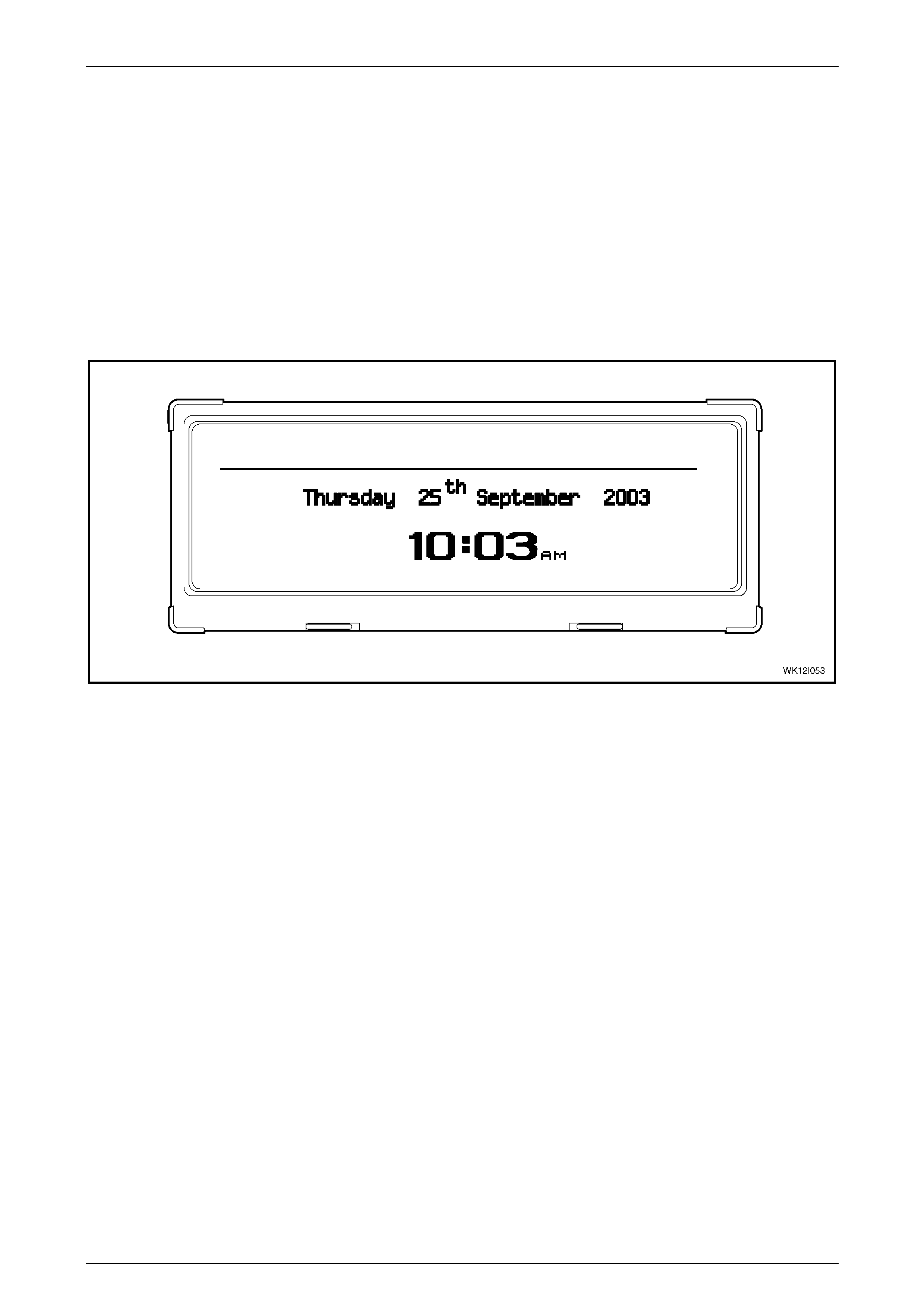
Time / Date Display
When the ignition is off, the date and time is displayed but the LCD will not be illuminated. When the ignition is on and
the audio system is off, the date and time is displayed and the LCD will be illuminated.
Figure 12I – 5
Multi Function Display Page 12I–8
Page 12I–8
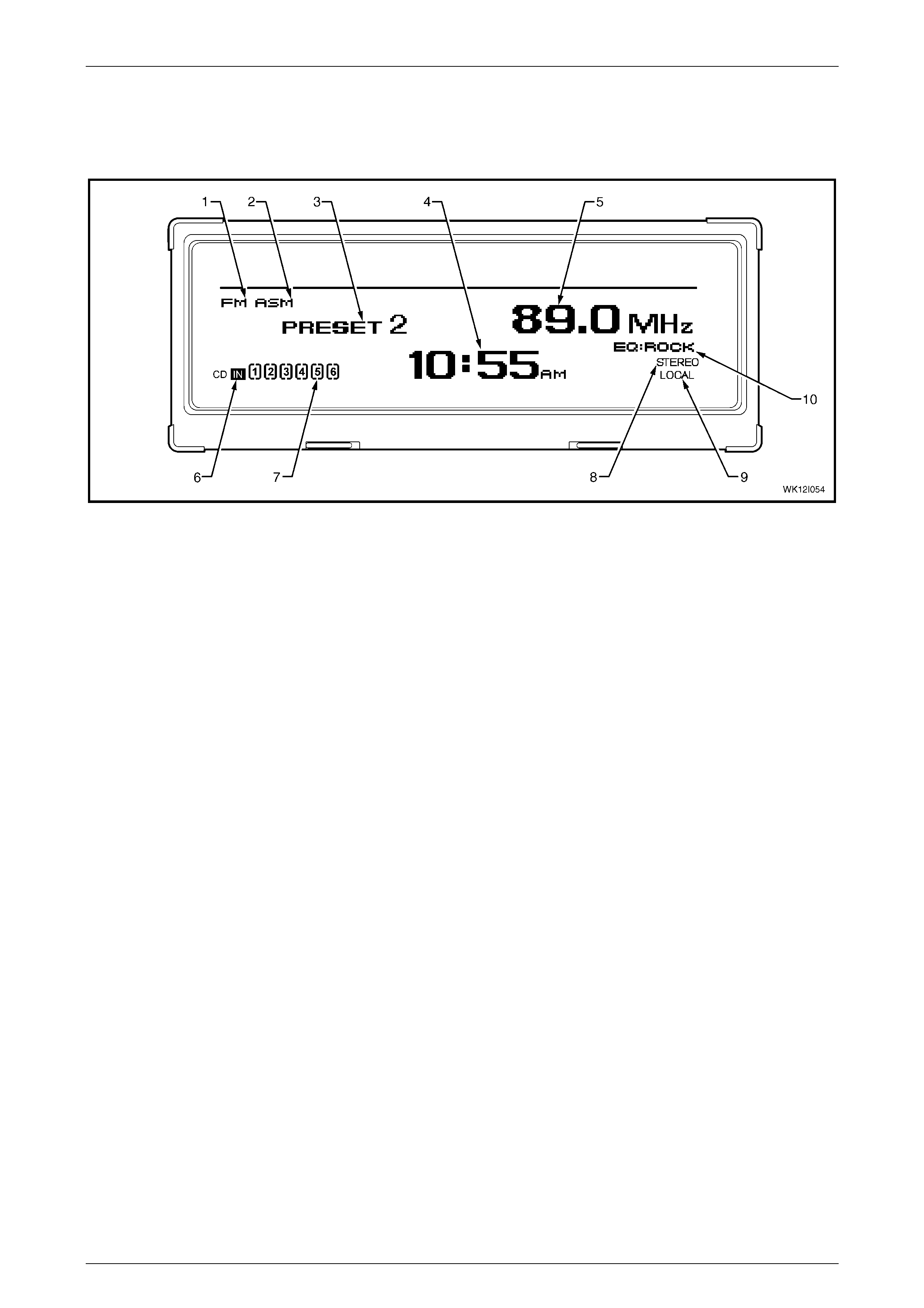
Radio Operation
When the key is in the ACC or ignition position and the audio system is operating with no auxiliary functions enabled, the
standard FM1 band radio preset display will appear as follows. If a station is manually selected, the indication PRESET 2
will cease to appear.
Figure 12I – 6
Legend
1 AM / FM Frequency Indicator 6 CD Inserted Indicator
2 Automatic Station Memory Indicator 7 CD Playing / Total Loaded Indicator
3 Station Preset Number 8 Stereo Sound Output Indicator
4 Time Display 9 Local / Distant Station Selection Indicator
5 Station Frequency Display 10 Equaliser Setting: Rock / Pop / Jazz / Classic / Vocal / Off
Multi Function Display Page 12I–9
Page 12I–9
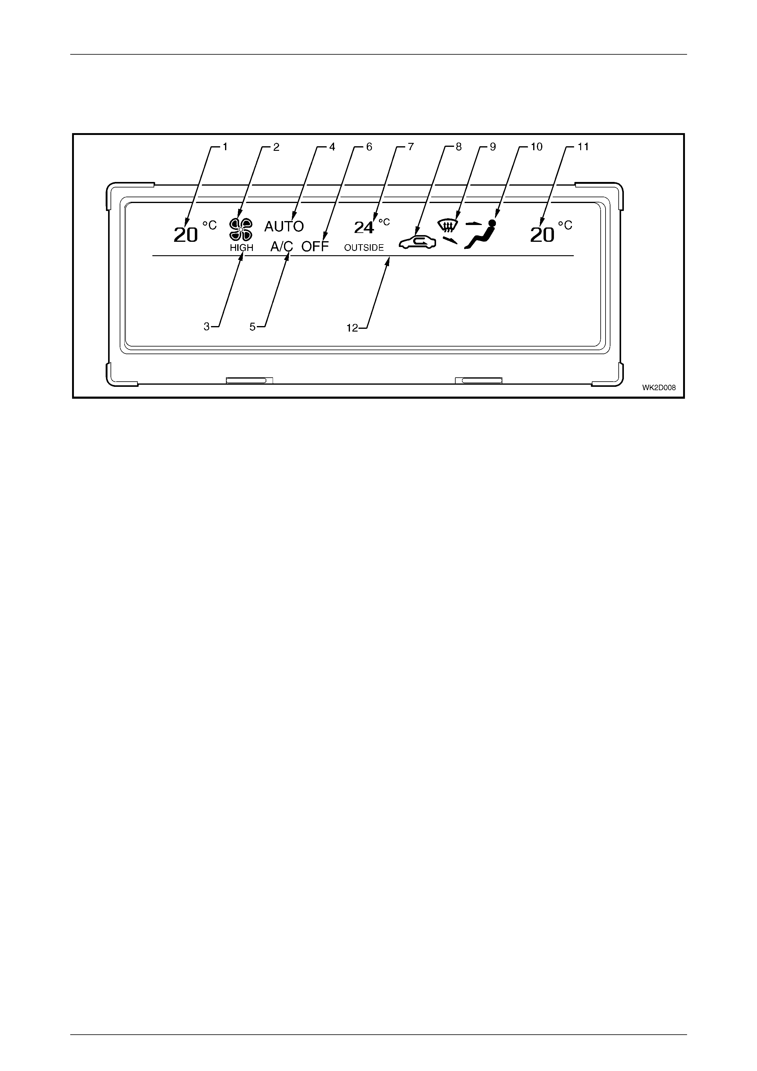
Heating Ventilation and Air Conditioning (HVAC) System Operation
The icons and information above the separation line of the MFD are devoted to Occupant Climate Control (Auto A/C)
heating and ventilation functions. The outside temperature is also displayed.
Figure 12I – 7
Legend
1 Left-hand Side Temperature Setting 7 Outside of Vehicle Temperature Indicator
2 Blower Fan 1, 2, 3, and 4 Speed Indicator 8 Recirculation Mode Active Indicator
3 Blower Fan Maximum Speed Indicator 9 Windscreen Demist Mode Active Indicator
4 OCC System In Auto Mode Indicator 10 Foot / Face / Bi-level Ventilation Mode Indicator
5 Air Conditioning On Indicator 11 Right-hand Side Temperature Setting
6 Air Conditioning Off Indicator 12 Audio / Time / Date Display and HVAC Display Separation Line
Multi Function Display Page 12I–10
Page 12I–10
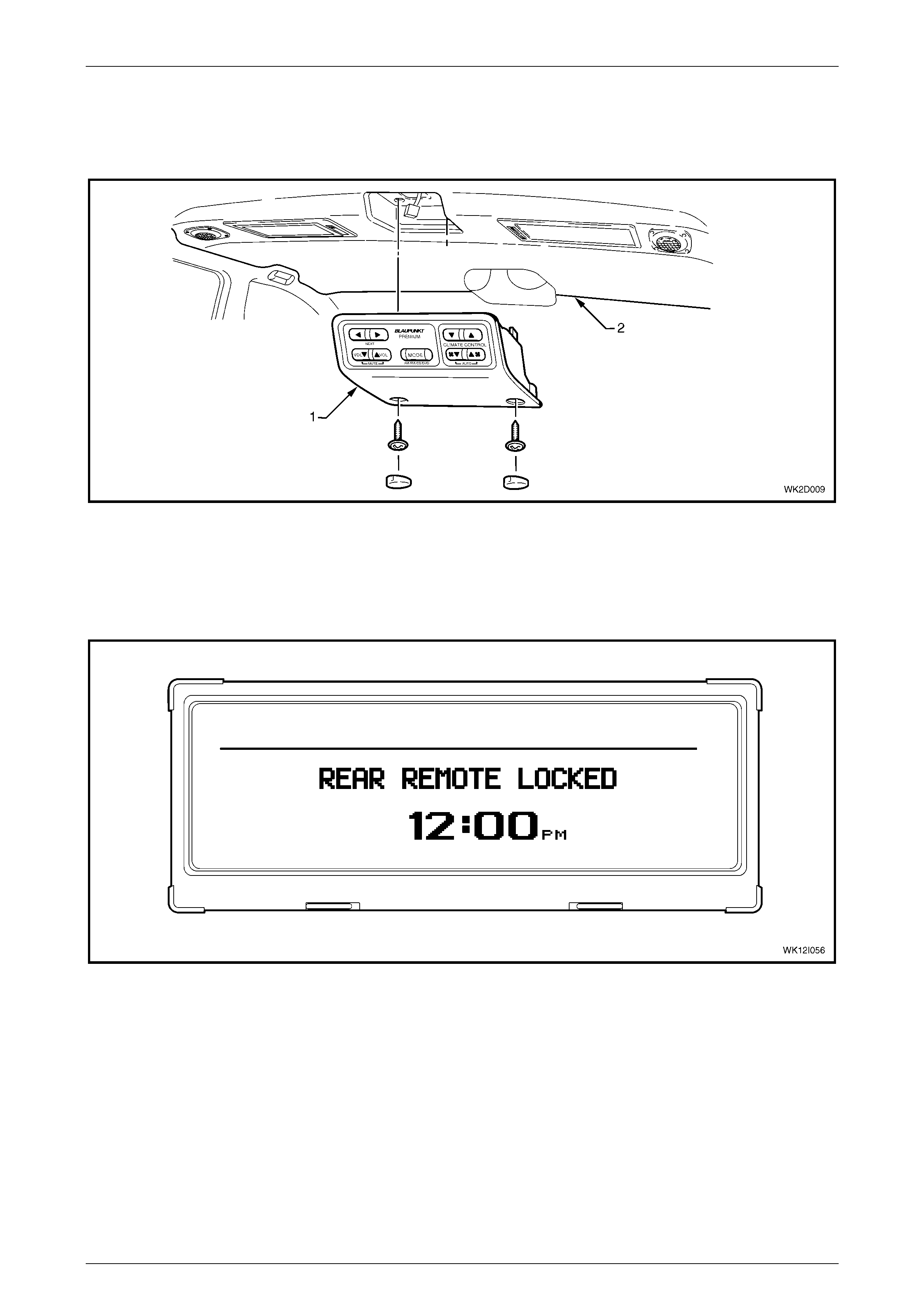
Rear Remote Control
On Level 5 MY2004 WK Series vehicles, rear passengers can access a rear remote control (1), which is fitted to the
centre of the headlining (2) forward of the rear passenger compartment. This unit combines a number of entertainment
system and Occupant Climate Control functions.
Figure 12I – 8
When the headphone switch on the audio head unit is pressed and held for more than 2 seconds, the following screen
will appear indicating that the rear remote cannot be used to alter audio system settings. The heating and ventilation
controls will remain operational from the rear remote control. The words REAR REMOTE LOCKED will be displayed on
the MFD screen for 3 seconds. After 3 seconds, the REAR REMOTE LOCKED message will then minimise and continue
to be displayed at the top, right-hand corner of the screen details displayed prior to pressing the headphone switch.
Figure 12I – 9
When the headphone switch on the audio head unit is pressed and held for more than 2 seconds while the rear remote is
in a locked state, the MFD screen will display a REAR REMOTE UNLOCKED message for 3 seconds. After 3 seconds,
the existing screen details displayed prior to pressing the headphone switch will then be displayed again without the
minimised REAR REMOTE LOCKED indication. Rear passengers may then alter audio settings via the rear remote
control.
For further information relating to the rear remote control as fitted to Level 5 MY2004 WK Series vehicles, refer to
Section 2D, 3.4 Rear Remote Control.
Multi Function Display Page 12I–11
Page 12I–11
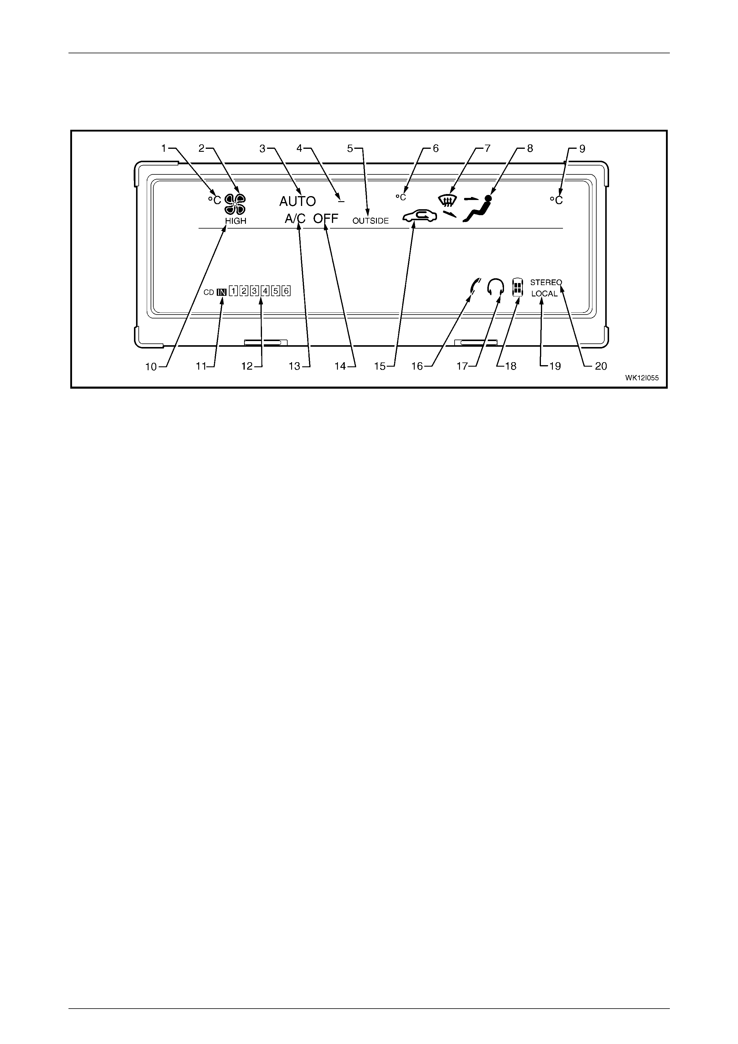
Fixed Icons
The following shows all available fixed icons on the MFD. They are brought up depending on the selected audio system
and HVAC system settings.
Figure 12I – 10
Legend
1 Left-hand Side Temperature Degree Celsius 11 CD Inserted Indicator
2 Blower Fan 1, 2, 3, and 4 Speed Indicator 12 CD Playing / Total Loaded Indicator
3 OCC System In Auto Mode Indicator 13 Air Conditioning On Indicator
4 Outside Temperature Minus Indicator 14 Air Conditioning Off Indicator
5 Outside Temperature Indicator 15 Recirculation Mode Active Indicator
6 Outside Temperature Degree Celsius 16 Phone Operation Indicator
7 Windscreen Demist Mode Active Indicator 17 Earphone Operation Indicator
8 Foot / Face / Bi-level Ventilation Mode Indicator 18 Listening Position (POS) Indicator
9 Right-hand Side Temperature Degree Celsius 19 Local / Distant Station Selection Indicator
10 Blower Fan Maximum Speed Indicator 20 Stereo Sound Output Indicator
If the OCC (Auto A/C) is active, the icons that are always visible while the power is on accessories or ignition are:
• Blower fan speed indicator (sequential shading and word HIGH dependant on blower fan speed setting)
• °C symbols for temperatures (unless Lo or Hi is chosen via the temperature switches)
• Passenger graphic showing current mode of air flow
• OUTSIDE – which indicates outside air temperature
If the audio system is active, the icons that are always visible while the power is on accessories or ignition are:
• CD IN boxes
• STEREO – automatically comes on when in FM mode or in CD mode
• HEADPHONE – symbol illuminates when the headphones are plugged in or the button pressed on the AHU

Multi Function Display Page 12I–12
Page 12I–12
Setting MFD Time / Date
The time / date display function of the MFD is usually set through the Audio Head Unit (AHU). However, it is not
dependant on the AHU to maintain this setting.
Procedure – Normal
When the audio system is on, the MFD displayed time and date can be set through the AHU as follows:
1 Press the TIME button for more than 2 seconds. The hour segment of the MFD screen will flash.
2 Adjust the hour setting using the ! SEEK TRACK and SEEK TRACK " buttons.
3 To adjust the minute setting, press the TIME button again. The minute segment of the MFD screen will flash.
4 Adjust the minute setting using the ! SEEK TRACK and SEEK TRACK " buttons.
5 Repeat this procedure until the year, month and date are set.
NOTE
The Program function of TECH 2 allows the MFD
time display to be set to a 24 hour clock or a
12 hour clock setting. Refer to 3.7 Program, F0:
Program Code Index in this Section.
Procedure – AHU Removed
If the audio system has been removed or replaced by a non-standard system, the MFD displayed time and date can be
set through the OCC control module as follows:
1 Turn the ignition on.
2 Press and hold both the AUTO and the driver’s side temperature ▲ buttons on the OCC control module for more
than 4 seconds. The hour segment of the MFD screen will flash.
3 Adjust the hours setting using the driver’s side ▲ and ▼ buttons.
4 To adjust the minute setting, press the AUTO button again. The minute segment of the MFD screen will flash.
5 Adjust the minute setting using the same ▲ and ▼ buttons.
6 Repeat this procedure until the year, month and date are set.
7 To exit this procedure, press and hold the OFF button for more than 2 seconds.
MFD Illumination
Illumination Adjustment
The MFD illumination level while the park lamps are ON
can be set from 0 to 100% using the variable intensity
illumination control slider (1) located on the headlamp
switch (2). When the park lamps are off, the MFD will be
at full illumination.
Illumination Adjustment Signal Path
The selected illumination level is sent to the MFD via the
BCM and the OCC control module. If there is a loss of
CAN communication between the MFD and the OCC
control module, the illumination level cannot be
controlled by the control slider at the headlamp switch.
Figure 12I – 11

Multi Function Display Page 12I–13
Page 12I–13
2 Service Operations
ATTENTION
All fasteners are important attaching parts as they affect the performance of vital components and / or could
result in major repair expense. Where specified in this section, fasteners MUST be replaced with parts of the
same part number or a GM approved equivalent. Do not use fasteners of an inferior quality or substitute
design.
Torque values must be used as specified during reassembly to ensure proper retention of all components.
Throughout this section, fastener torque wrench specifications may be accompanied with the following
identification marks:
!
!!
! Fasteners must be replaced after loosening.
"
""
" Vehicle must be at kerb height before final tightening.
#
##
# Fasteners either have micro encapsulated sealant applied or incorporate a mechanical thread lock and
should only be re-used once. If in doubt, replacement is recommended.
If one of these identification marks is present alongside a fastener torque wrench specification, the
recommendation regarding that fastener must be adhered to.
2.1 Multi Function Display
Remove
LT Section – 09-300
1 Remove the console cover assembly and if fitted, the navigation system components. Refer to Section 1A3,
2.1 Floor Console Cover Assembly in the MY 2003 VY and V2 Series Service Information.
2 Remove the audio head unit (AHU), refer to Section 12D, 2.1 Audio System Head Unit.
Using tools to prise off components may
damage the instrument panel, the instrument
panel upper centre trim panel and / or the
centre trim assembly.
Multi Function Display Page 12I–14
Page 12I–14
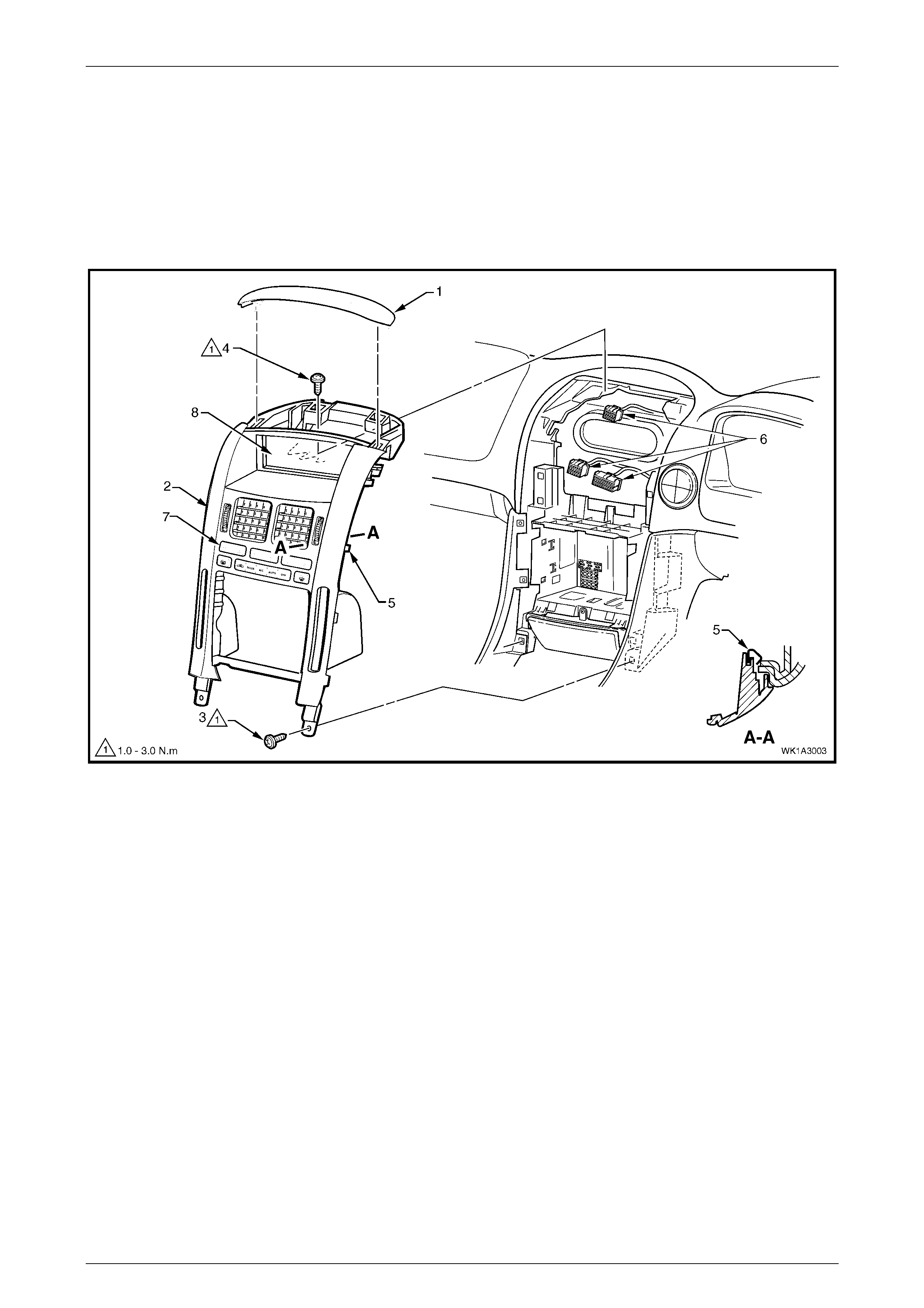
3 Carefully prise the front edge of the instrument panel upper centre trim panel (1), and pull upward to disengage the
retaining clips at each corner from the centre trim assembly (2), refer to Figure 12I – 12.
4 Remove the two lower screws (3) attaching the centre trim assembly to the instrument panel.
5 Remove the two upper screws (4) attaching the centre trim assembly to the instrument panel.
6 Remove the centre trim assembly, disengaging the four clips (5), far enough to disconnect the wiring connectors (6)
from the rear of the MFD (8) and the OCC control module (7).
7 Remove the centre trim assembly.
Figure 12I – 12
Multi Function Display Page 12I–15
Page 12I–15
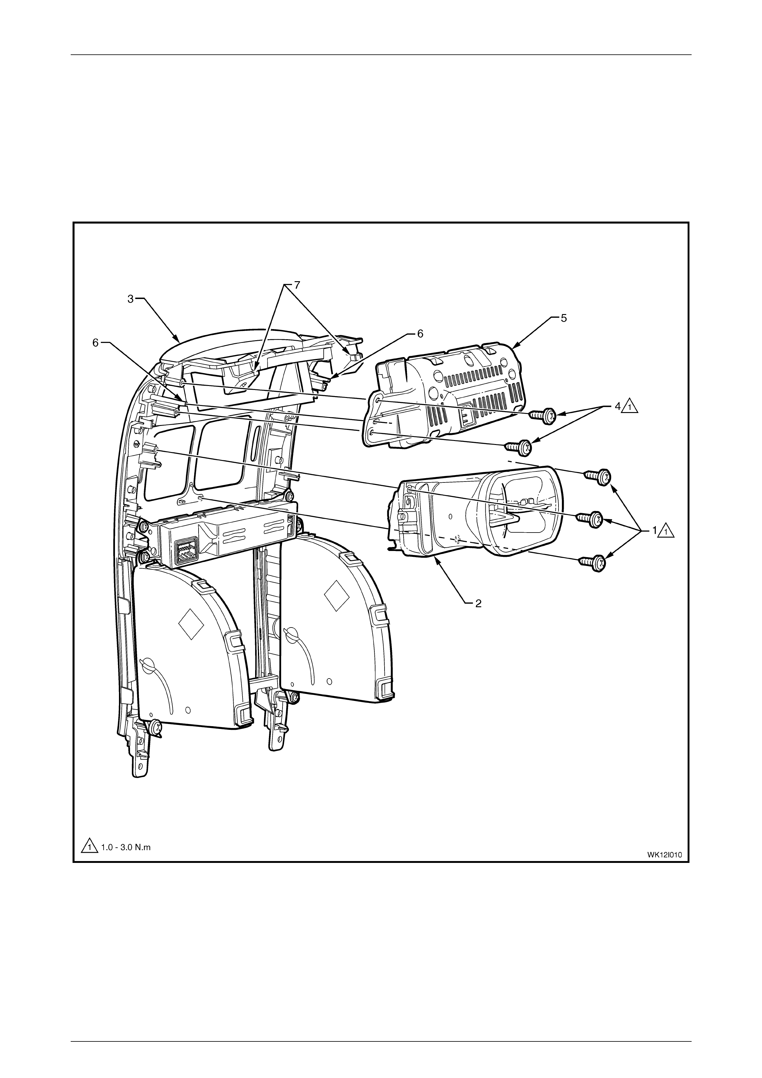
8 Remove the three screws (1) attaching the instrument panel centre air outlet housing assembly (2) to the centre
trim assembly (3), refer to Figure 12I – 13.
9 Remove the centre air outlet housing assembly from the centre trim assembly.
10 Remove the four screws (4) attaching the MFD (5) to the back of the centre trim assembly.
11 Pull the MFD rearwards clear of the locating dowels (6), and then downward clear of the centre trim assembly
upper mounts (7).
12 Remove the MFD from the centre trim assembly.
Figure 12I – 13

Multi Function Display Page 12I–16
Page 12I–16
Reinstall
Installation is the reverse of the removal procedures. Tighten all screws to the specified torque.
MFD attaching screw
torque specification .................................... 1.0 – 3.0 Nm
Centre air outlet housing
assembly attaching screw
torque specification .................................... 1.0 – 3.0 Nm
Instrument panel centre trim
assembly attaching screw
torque specification .................................... 1.0 – 3.0 Nm

Multi Function Display Page 12I–17
Page 12I–17
3 Diagnosis
3.1 MFD Diagnostics
Diagnostic Trouble Codes
When a fault is detected, the MFD sets a Diagnostic Trouble Code (DTC) that represents that particular problem or
failure. The DTC remains current as long as the fault remains, and is cleared when the fault is rectified. The DTC can be
read and cleared using TECH 2.
For further details on each of the DTCs, refer to 3.8 Multi Function Display Diagnostic Procedures in this Section.
Multi Function Display Page 12I–18
Page 12I–18
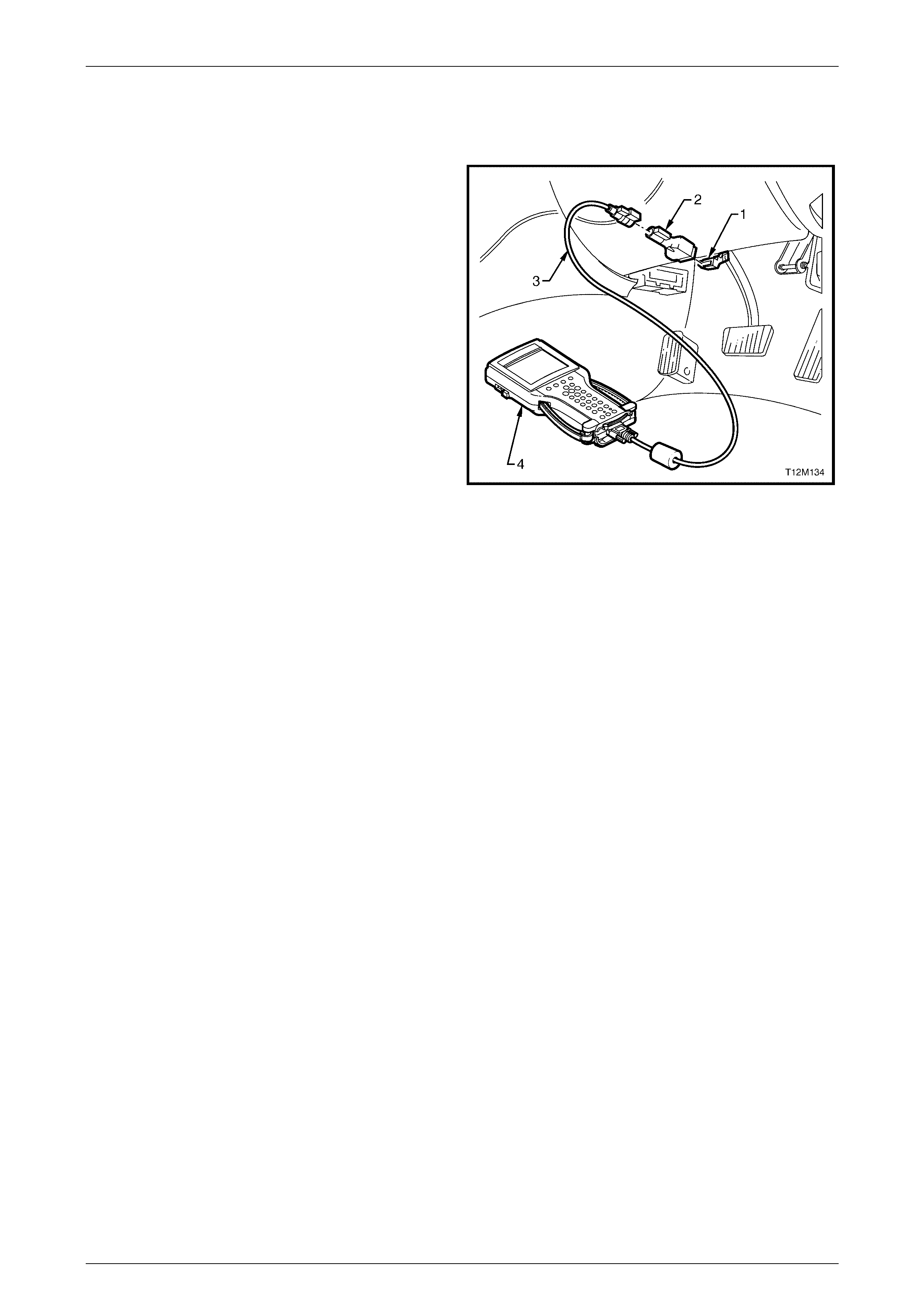
3.2 Connecting TECH 2 For System
Diagnosis
TECH 2, with the appropriate software, cables and
adaptors, is capable of reading serial data associated with
the MFD when connected to the Data Link Connector
(DLC). The DLC is connected to the instrument panel lower
right-hand trim (left-hand trim for LHD vehicles), beneath the
steering column.
1 Data Link Connector (DLC)
2 DLC Adaptor
3 DLC Cable
4 TECH 2
For additional general information on connecting and
operating TECH 2, refer to Section 0C TECH 2.
Figure 12I – 14
Multi Function Display Page 12I–19
Page 12I–19
3.3 TECH 2 Test Modes and Displays
A prerequisite of this diagnostic section is for the user to be familiar with the proper use of TECH 2. The following pages
illustrate only the major TECH 2 screen displays and provide a brief explanation of their function for diagnosing the audio
system. If additional information is required on the operation of TECH 2, reference should be made to either Section 0C
TECH 2 of this Service Information or the TECH 2 User’s Guide.
With the ignition turned off, connect TECH 2 to the Data Link Connector (DLC) using the DLC Adaptor, refer to
3.2 Connecting TECH 2 For System Diagnosis.
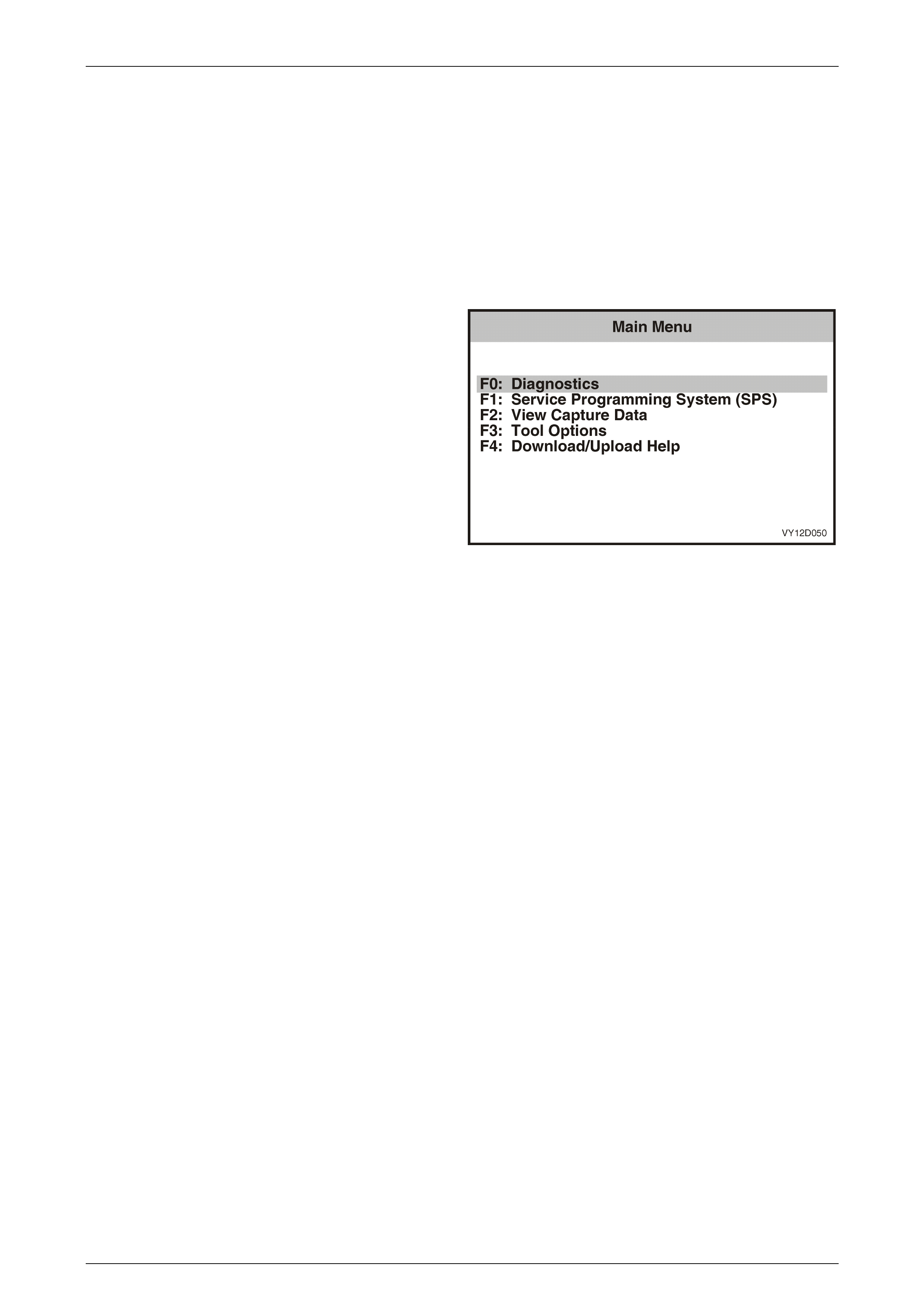
Main Menu
Turn the ignition on and press the power button (PWR) on
the TECH 2.
The TECH 2 will perform a series of self-diagnosing power
on self-tests (POST). Once this has been completed
successfully, the TECH 2 start up screen will be displayed.
Press the Enter key to continue.
The Main Menu screen is displayed.
Press the F0 function button or Select F0: Diagnostics by
using the arrow keys until F0: Diagnostics is highlighted and
press the Enter key.
Figure 12I – 15
Multi Function Display Page 12I–20
Page 12I–20
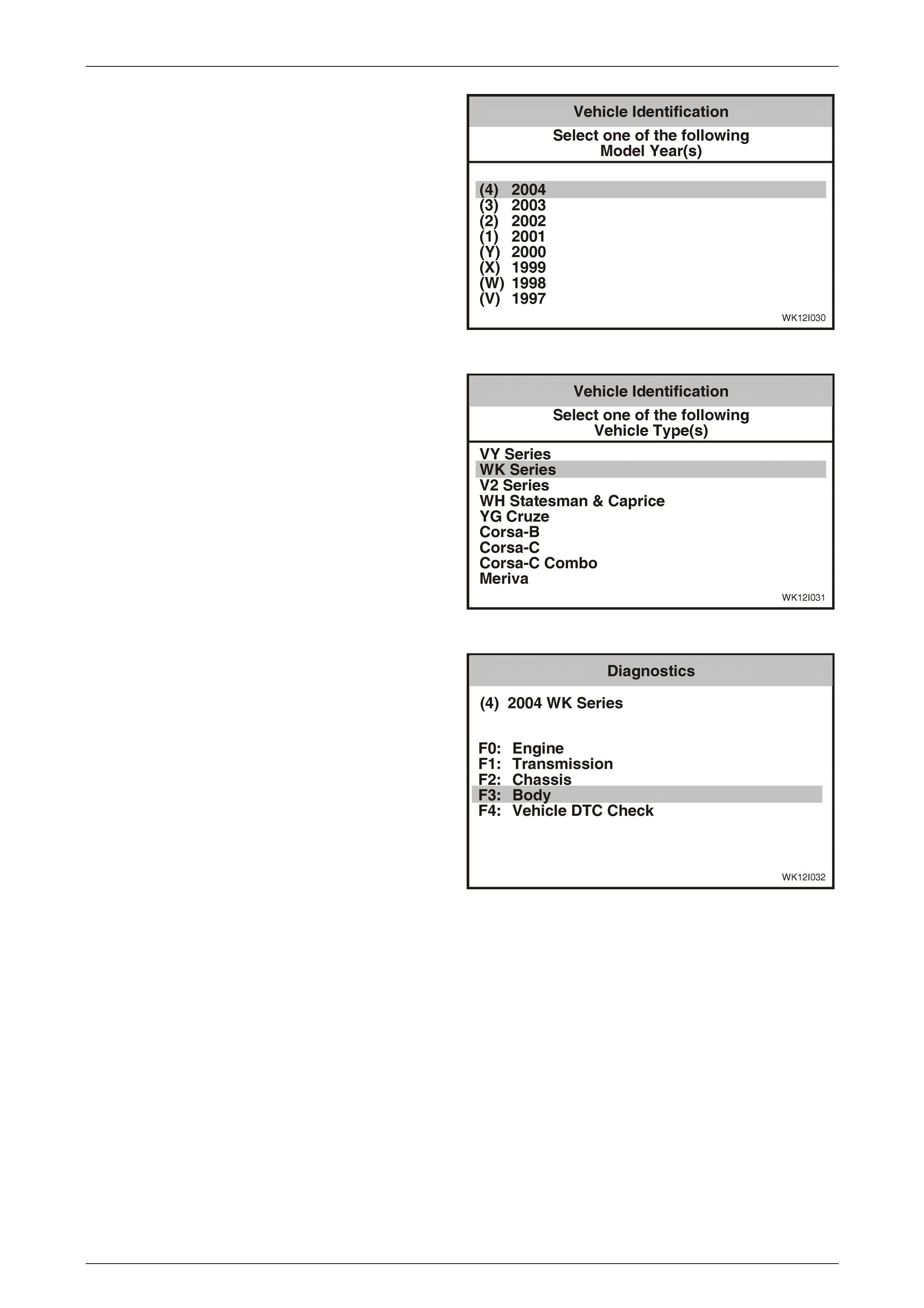
Model Year
Select the relevant model year from the list and press Enter.
Figure 12I – 16
Vehicle Identification Menu
Select the appropriate vehicle type from the list and press
Enter.
Figure 12I – 17
System Selection Menu
Select F3: Body from the System Selection Menu and press
Enter.
Figure 12I – 18
Multi Function Display Page 12I–21
Page 12I–21
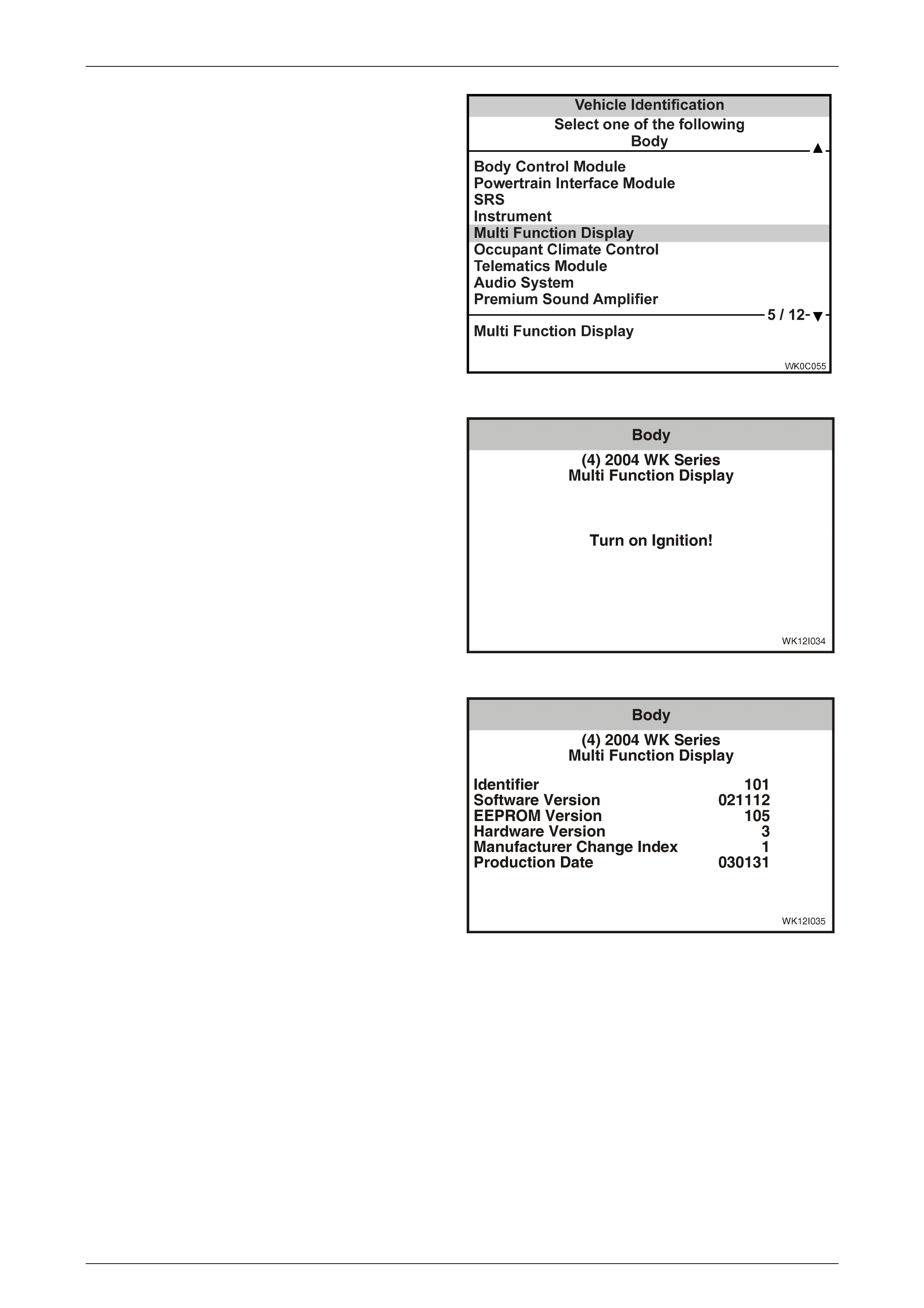
Multi Function Display Selection
Select Multi Function Display and press Enter.
Figure 12I – 19
Turn the ignition on if not on already (as requested) and
press the Confirm soft key to continue.
Figure 12I – 20
The Multi Function Display identification details will be
displayed. Scroll through the list using the TECH 2 Up and
Down arrows.
Figure 12I – 21
Multi Function Display Page 12I–22
Page 12I–22
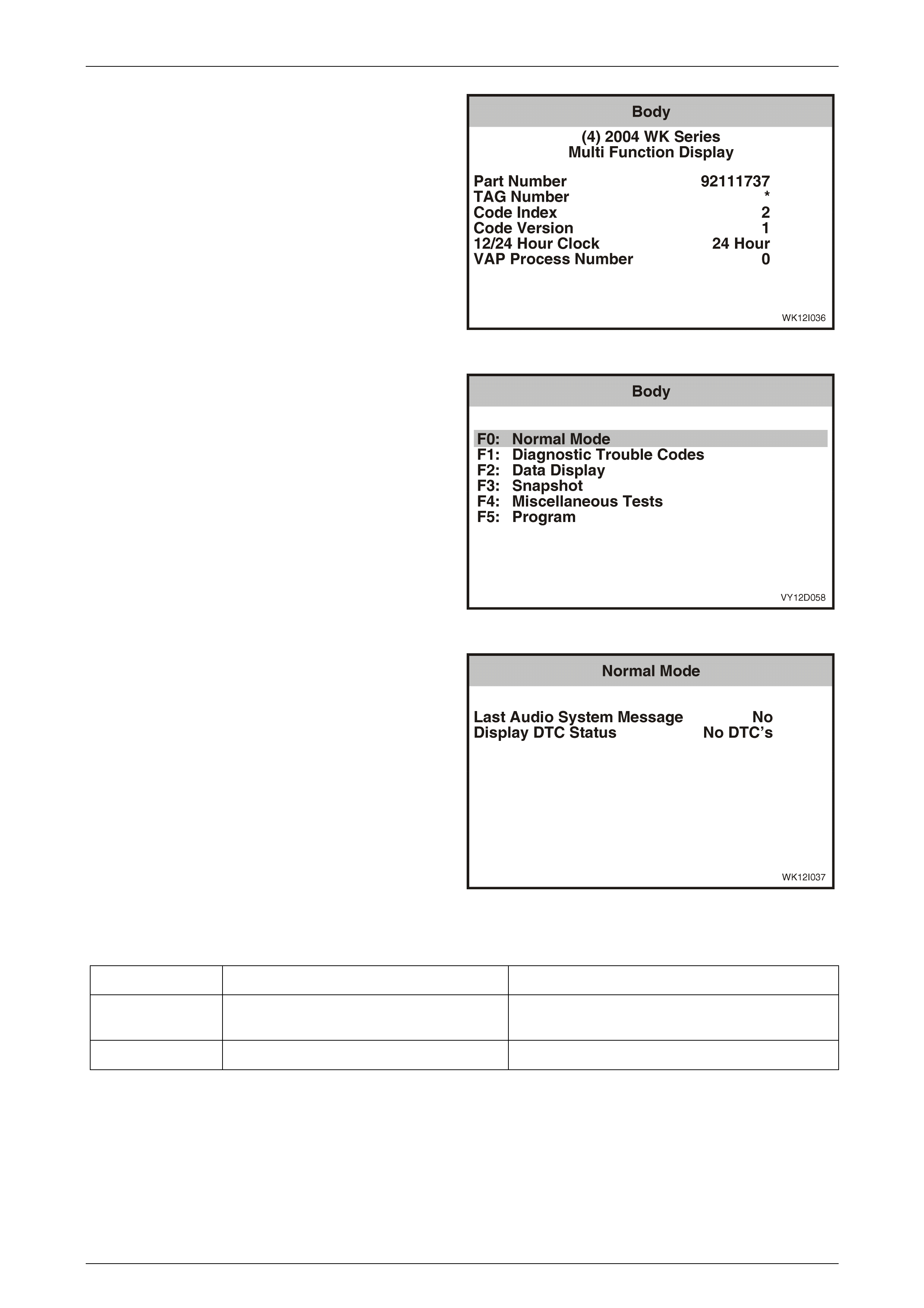
Press the Confirm soft key to confirm these details.
Figure 12I – 22
Body Menu
The following functions will now be available:
1 F0: Normal Mode
2 F1: Diagnostic Trouble Codes
3 F2: Data Display
4 F3: Snapshot
5 F4: Miscellaneous Tests
6 F5: Program
Figure 12I – 23
F0: Normal Mode
Details of the serial data in the normal mode data list are
provided in the following table.
Figure 12I – 24
Normal Mode Data List
TECH 2 Displa y Range Remarks
Last Audio System
Message
Yes/No
Display DTC Status No DTC / DTC's Set Indicates whether any DTCs are set.
Multi Function Display Page 12I–23
Page 12I–23
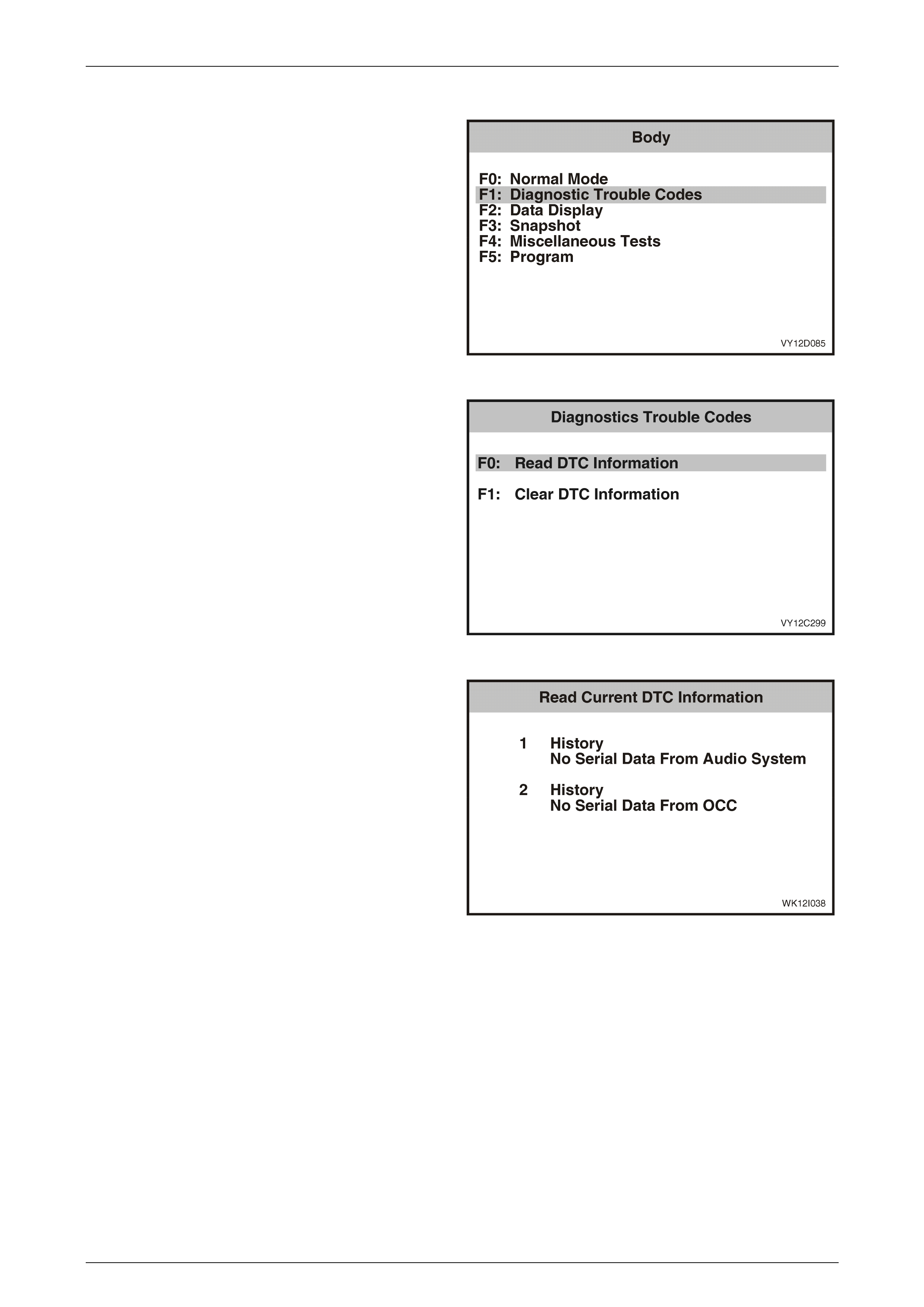
F1: Diagnostic Trouble Codes
1 From the Body Menu select Diagnostic Trouble Codes
and press the Enter key.
Figure 12I – 25
2 Scroll through the Diagnostic Trouble Codes list using
the TECH 2 Up and Down arrows. To select the
required item, press the Enter key.
F0: Read DTC Information. If this mode is selected, a
listing of all (if any) DTCs that have been set by the MFD will
be displayed.
F1: Clear DTC Information. DTC can be cleared in this
mode by simply selecting F1: Clear DTC Information,
pressing the Enter key on TECH 2 and confirming the action
as instructed by TECH 2.
NOTE
TECH 2 will display Clear DTC Information
Failed if any DTC are still current.
Figure 12I – 26
Read Current DTC Information
If any DTCs are set, reference should be made to the
relevant diagnostic charts in this Section. For more detail on
reading DTCs refer to Section 0C TECH 2.
NOTE
This illustration shows an example of two DTCs.
The following table identifies DTCs applicable to
the Multi Function Display.
The example also indicates that the two DTCs
are history code, i.e. the fault was present but
has since disappeared (possibly an indication of
an intermittent fault). A DTC is current if it is
recognised by the system on the current ignition
cycle.
Figure 12I – 27
Diagnostic Trouble Codes
The following DTC codes can be set by the MFD:
• No Serial Data from Audio System,
• No Serial Data from OCC, and
• EEPROM Error.
Multi Function Display Page 12I–24
Page 12I–24
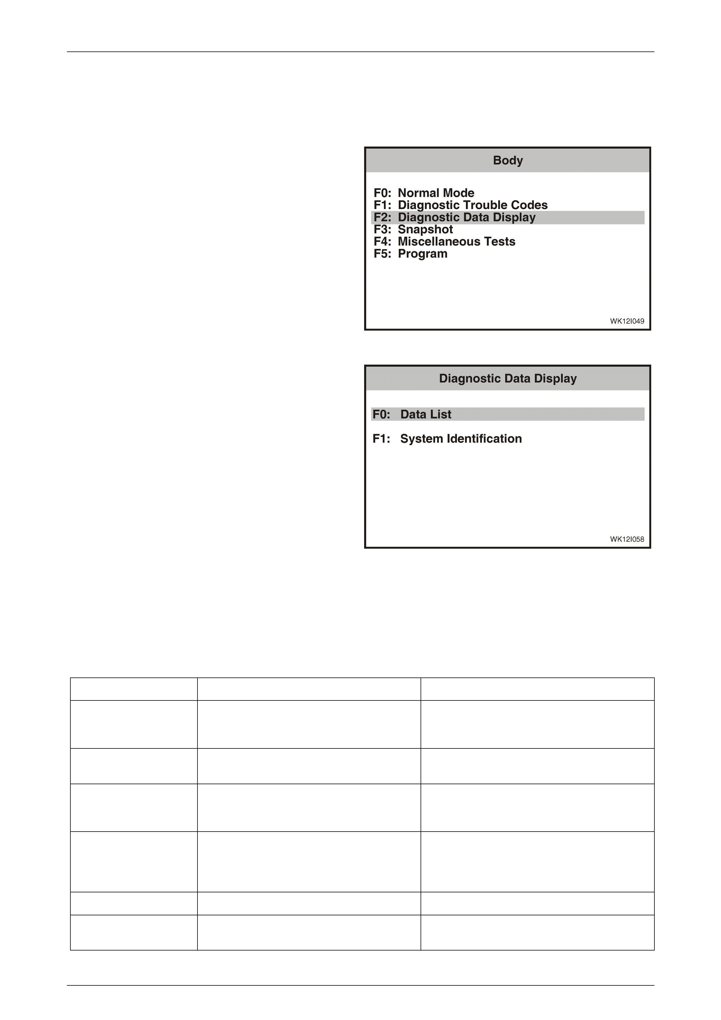
3.4 Data Display
The Data Display function allows the status of the MFD inputs and outputs to be monitored, as well as the system
identification details.
1 From the Body Menu select F2: Diagnostic Data
Display and press the Enter key.
Figure 12I – 28
2 Scroll through the Diagnostic Data Display list using
the TECH 2 Up and Down arrows. To select the
required item, press the Enter key.
F0: Data List. If this mode is selected, a listing of all serial
data associated with the MFD will be displayed.
F1: System Information. Provides details of system
identification.
Figure 12I – 29
F0: Data List
The serial data from the MFD can be checked and tested by selecting the item and pressing the Select Items soft key.
The list can be scrolled by using the Up and Down arrow keys.
Data Display List
TECH 2 DISPLAY RANGE REMARKS
Battery Voltage Volts Unregulated, can vary according to the power
load drawn by other systems operating in the
vehicle e.g. rear demister.
Park Lamp Switch On / Off Park lamp status at connector P5, terminal
X1-3. Displays On when the park lamp is On.
Accessory Relay On / Off Accessory relay status at connector P5,
terminal X1-12. Displays On when the
accessory relay is on.
MFD Illumination 0–100% Illumination level is set with the variable
intensity illumination control slider on the
headlamp switch. Refer to 1.2 System
Operation, MFD Illumination in this Section.
DTC Status No DTC / DTC's Set Indicates whether there are DTCs set
Number of ignition cycles
since last DTC
0–255 Every time a new DTC is set, the count returns
to 0.

Multi Function Display Page 12I–25
Page 12I–25
F1: System Identification
The System Identification screen provides production
information relevant to the MFD.
Figure 12I – 30
Multi Function Display Page 12I–26
Page 12I–26
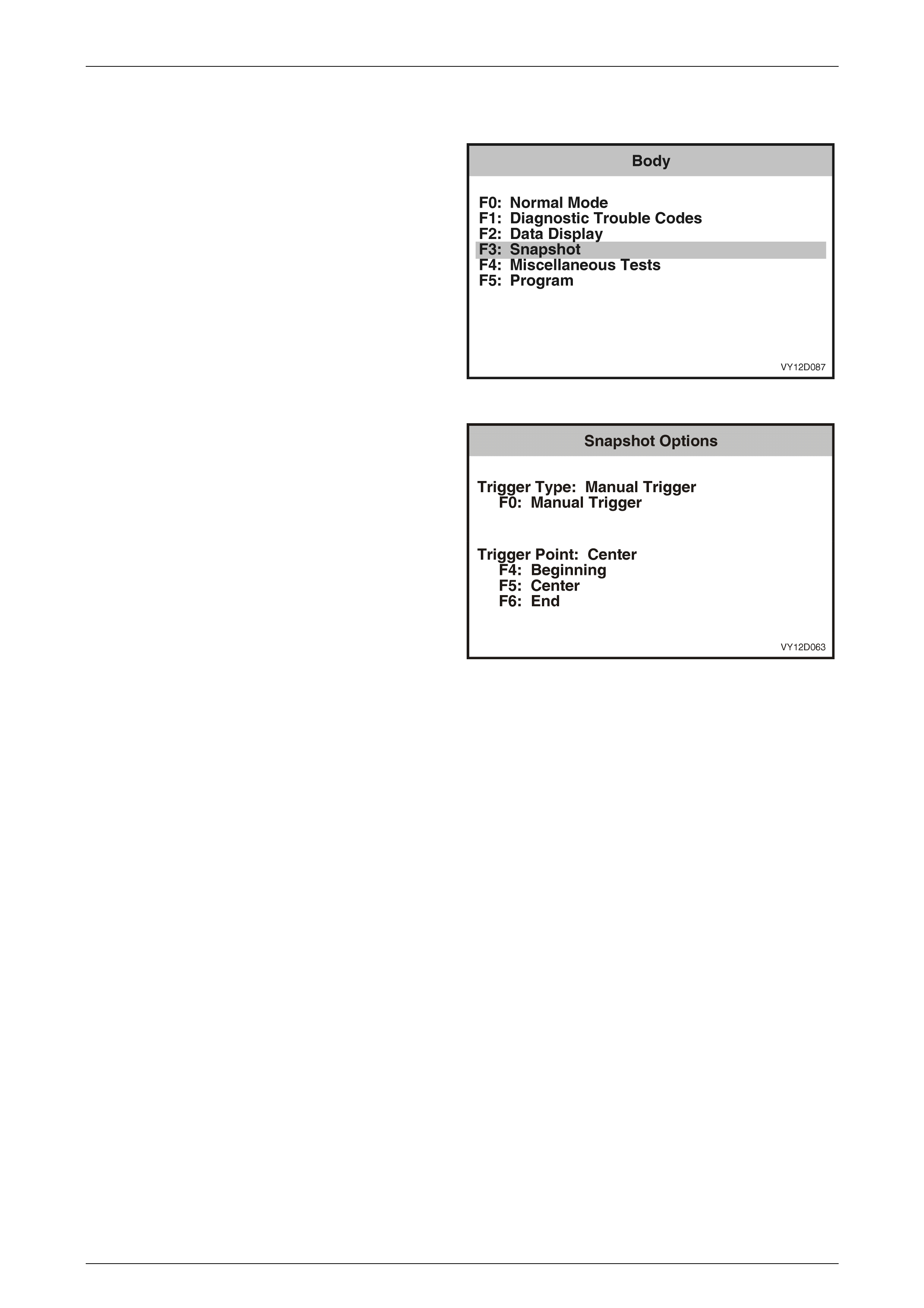
3.5 Snapshot
From the Body Menu select F3: Snapshot and press the
Enter key.
Figure 12I – 31
The TECH 2 can be used to record system information that
is occurring at a particular moment in time, and this is called
a snapshot. For more details refer to the TECH 2 User's
guide.
Figure 12I – 32
Multi Function Display Page 12I–27
Page 12I–27
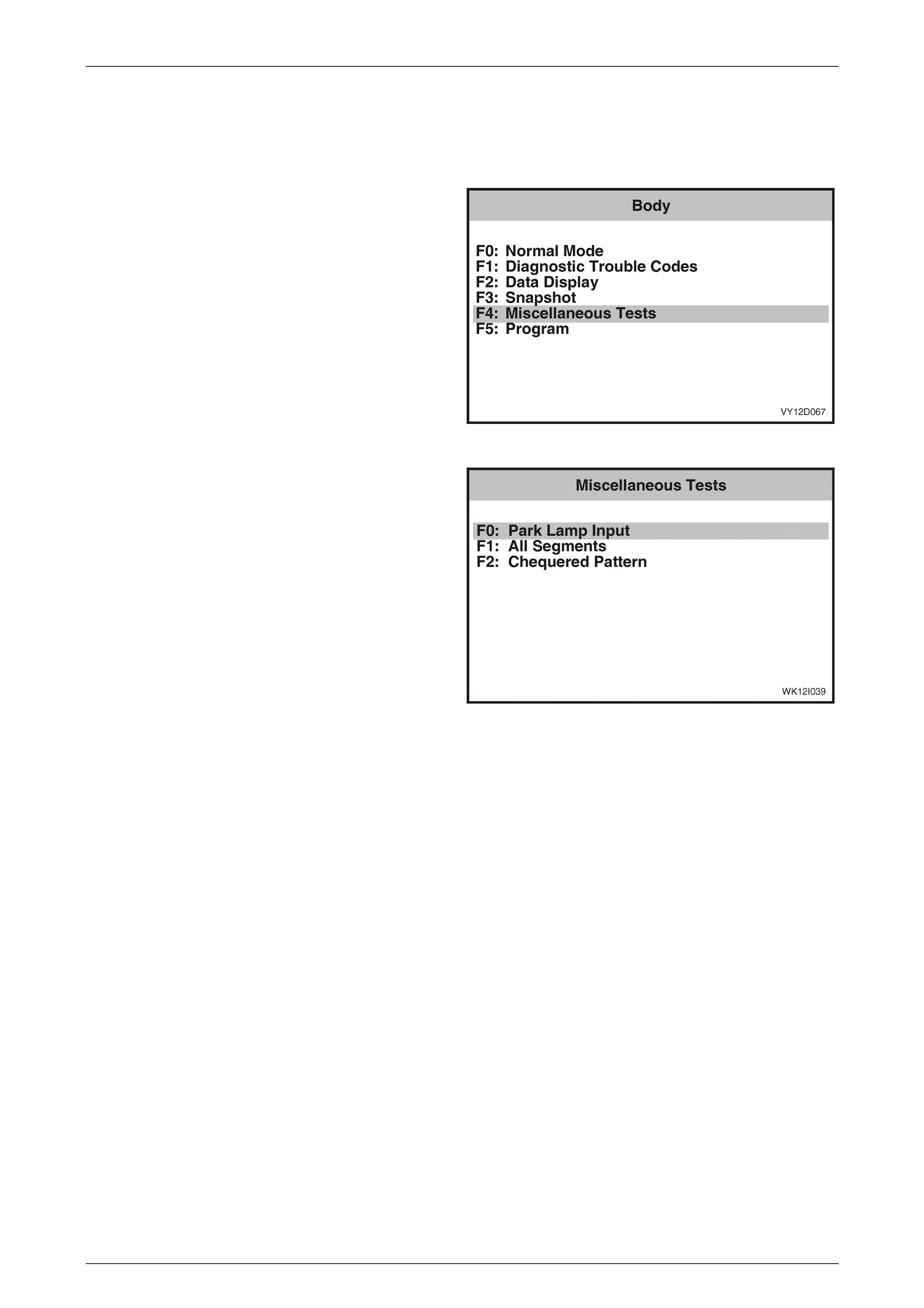
3.6 Miscellaneous Tests
The TECH 2 can be used to verify correct operation of the various functions of the MFD to assist in isolating a fault
condition. The TECH 2 can be used to force various functions On or Off and monitor the response.
1 From the Body Menu select F4: Miscellaneous Tests
and press the Enter key.
Figure 12I – 33
2 Scroll through the Miscellaneous Tests using the
TECH 2 Up and Down arrows. To select the required
test, press the Enter key.
Figure 12I – 34
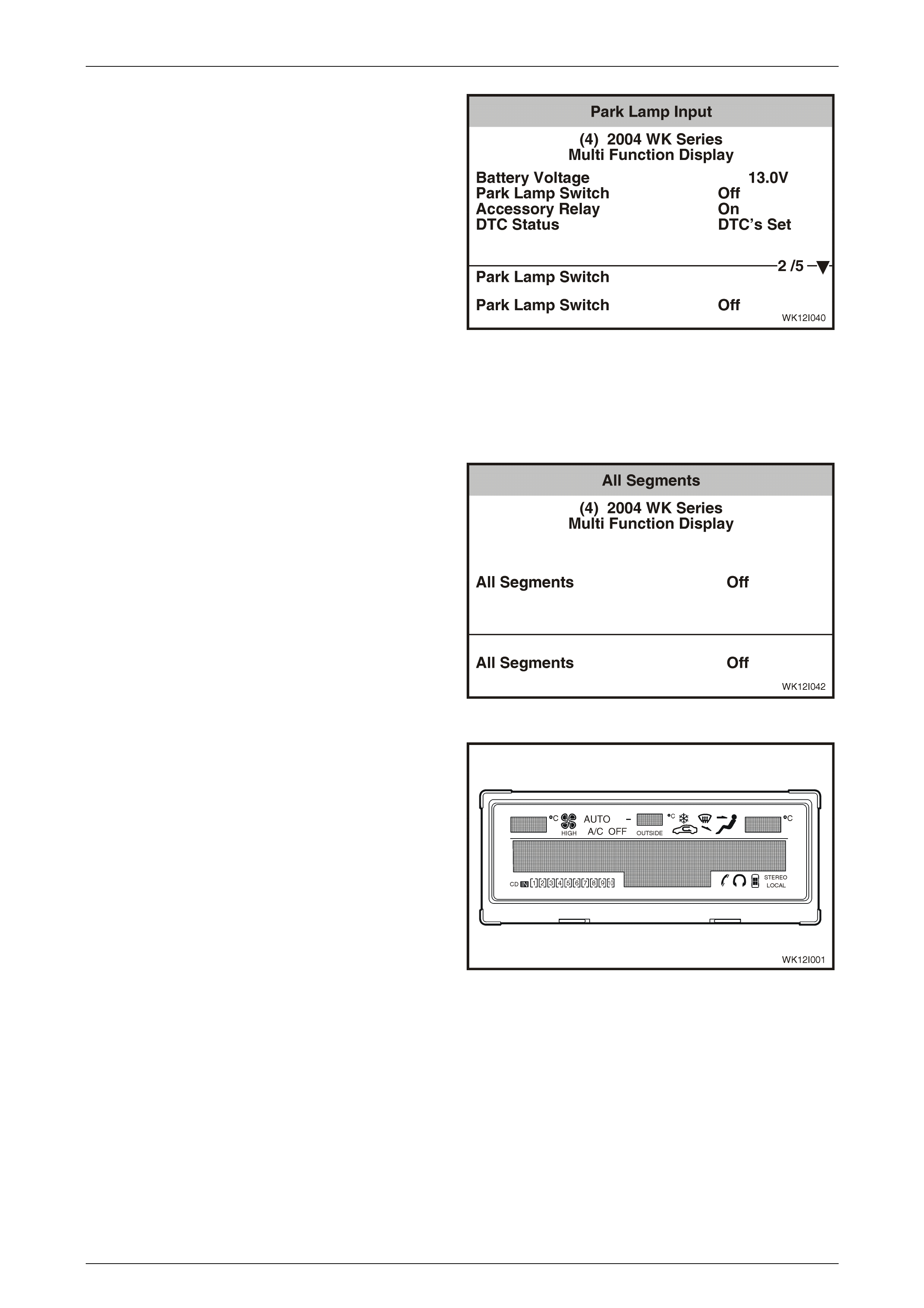
F0: Park Lamp Input
The selected illumination level is sent from the headlamp switch to the MFD via the BCM and the OCC control module.
When the park lamps are switched off, the MFD is at full illumination. When the park lamps are switched on, the MFD
dims to the level previously set by the variable intensity illumination control slider on the headlight switch.
NOTE
If the illumination intensity is set to 0%, the MFD
LEDs will turn off when the park lamps are
switched on.
1 Turn the ignition On and the headlamps switch to the park lamps On position.
2 Reduce MFD Illumination to less than 60% using the variable intensity illumination control slider on the headlight
switch.
3 On TECH 2 select Park Lamp Input.
Multi Function Display Page 12I–28
Page 12I–28
4 The TECH 2 will display the current park lamp switch
status and MFD illumination.
5 Press the On soft key on the TECH 2 to switch the
park lamps on. Verify that the MFD dims and the park
lamp switch status is reflected in the TECH 2 screen.
6 Press the Off soft key on the TECH 2 to switch the
park lamps off. Verify that the MFD brightens and the
park lamp switch status is reflected in the TECH 2
screen
7 Press the Quit soft key on the TECH 2 to exit the test.
Figure 12I – 35
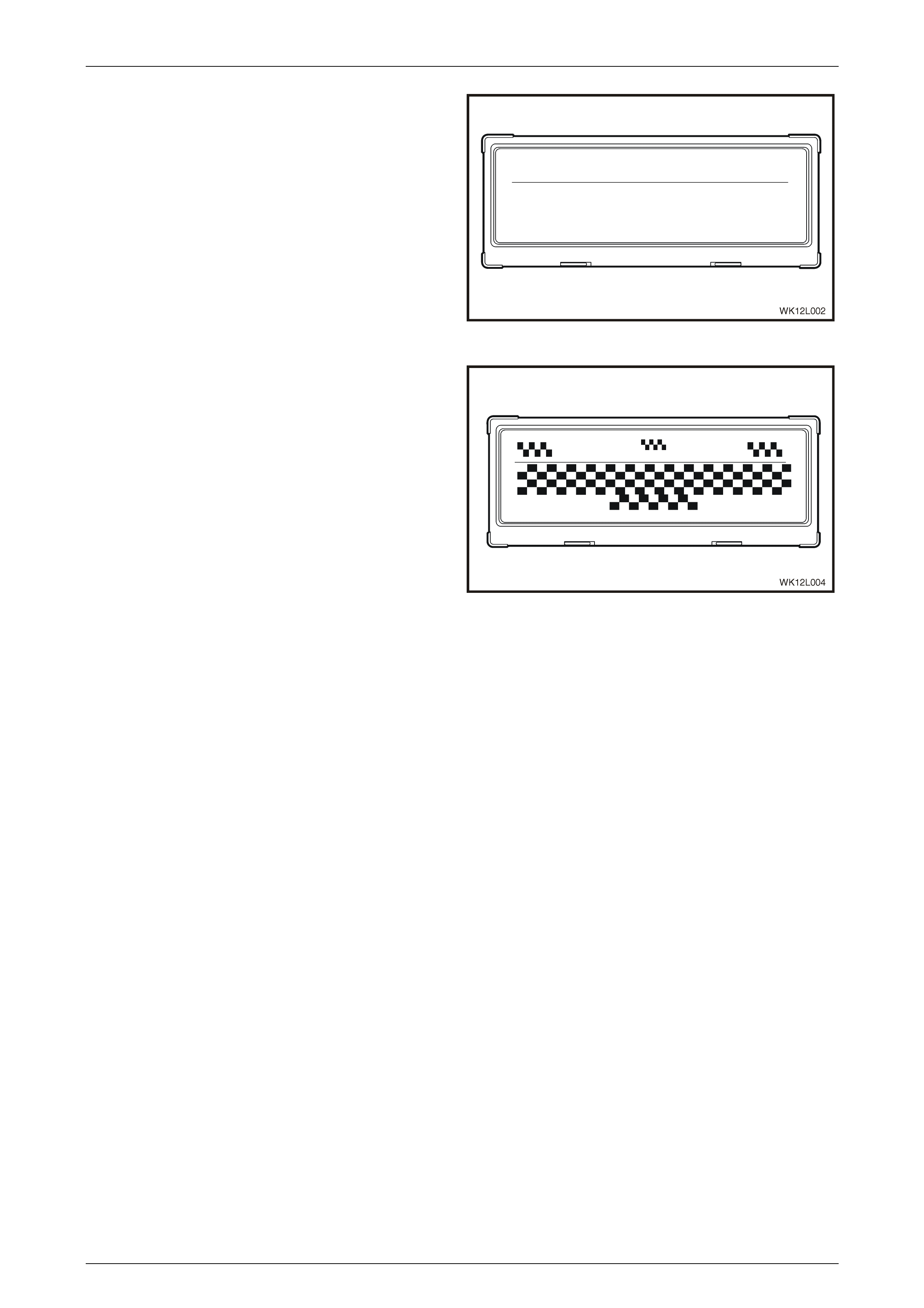
F1: All Segments
This test is performed using the TECH 2 and verifies that the Multi Function Display LCD is able to illuminate all
segments.
1 On the TECH 2 select Diagnostics / Model Year /
Vehicle Model / Body / Multi Function Display /
Miscellaneous Tests / All Segments.
2 The TECH 2 will display the current status of the All
Segments test.
Figure 12I – 36
3 Press the On soft key on the TECH 2 to switch All
Segments On. Verify that the MFD LCD display
illuminates all segments and that the All Segments
status is reflected in the TECH 2 screen. If the MFD
LCD fails to illuminate all segments as shown, replace
the MFD.
Figure 12I – 37
Multi Function Display Page 12I–29
Page 12I–29
3 Press the Off soft key on the TECH 2 to switch All
Segments Off. Verify that the MFD LCD display goes
blank and that the All Segments status is reflected in
the TECH 2 screen. If the MFD LCD fails to clear all
segments as shown, replace the MFD.
4 Press the Quit soft key on the TECH 2 to exit the All
Segments test.
To test the Illumination of OCC specific information (upper
section of MFD display), refer to HVAC LCD Display Test in
this Section.
Figure 12I – 38
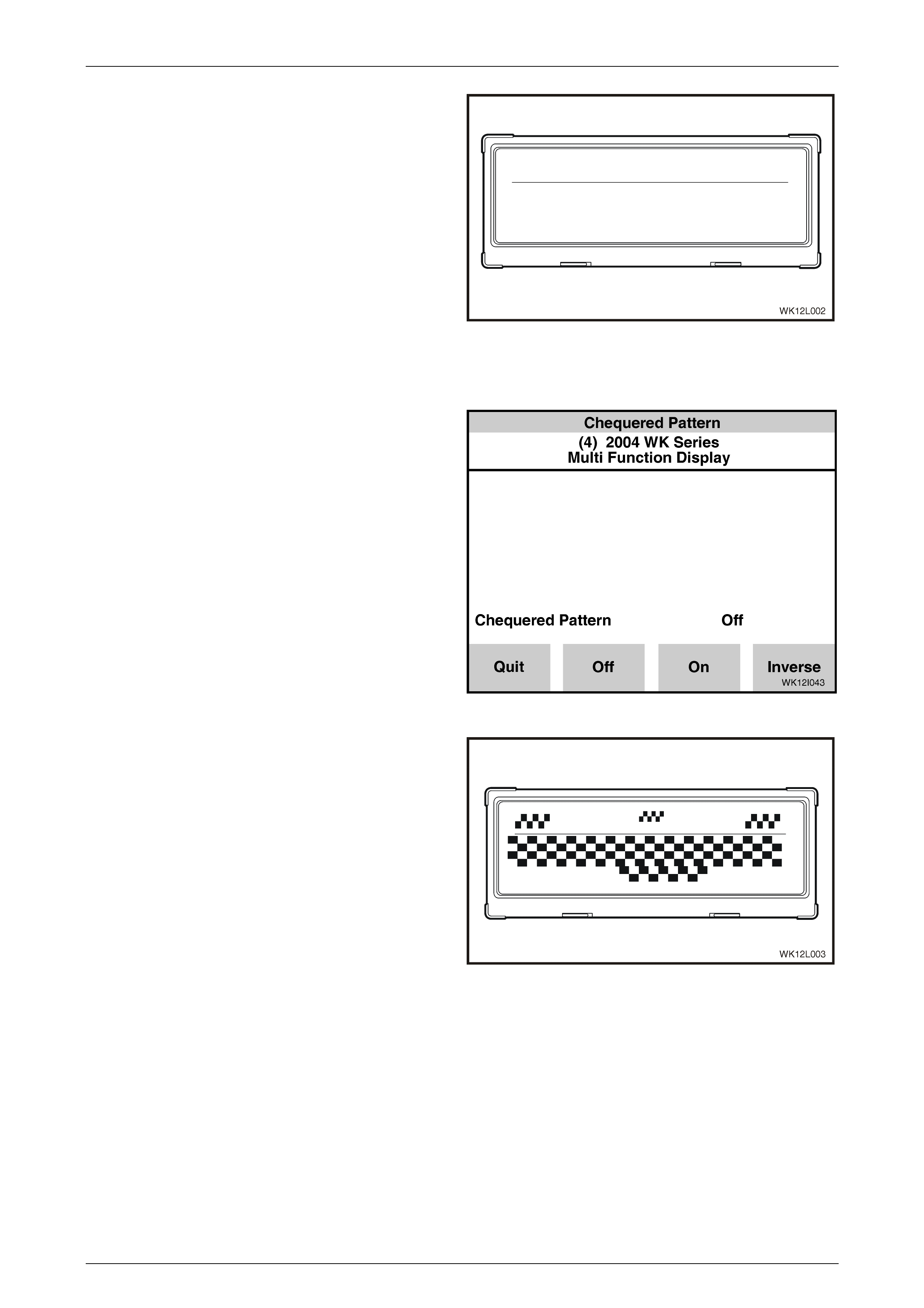
F2: Chequered Pattern
1 In the TECH 2 select Diagnostics / Model Year /
Vehicle Model / Body / Multi Function Display /
Miscellaneous Tests / Chequered Pattern.
2 The TECH 2 will display the current status of the
Chequered Pattern test.
Figure 12I – 39
3 Press the On soft key on the TECH 2 to switch
Chequered Pattern On. Verify that the MFD LCD
display illuminates a chequered pattern and that the
Chequered Pattern status is reflected in the TECH 2
screen. If the MFD LCD does not illuminate the
chequered pattern shown, replace the MFD.
Figure 12I – 40
Multi Function Display Page 12I–30
Page 12I–30
4 Press the Off soft key on the TECH 2 to switch
Chequered Patterns Off. Verify that the MFD LCD
display goes blank and that the Chequered Pattern
status is reflected in the TECH 2 screen. If the MFD
LCD does not clear all segments as show, replace
the MFD.
Figure 12I – 41
5 Press the Inverse soft key on the TECH 2 to switch
Inverse Chequered Pattern On. Verify that the MFD
LCD display illuminates an inverse chequered pattern
and that the Inverse Chequered Pattern status is
reflected in the TECH 2 screen. If the MFD LCD does
not illuminate the inverse chequered pattern shown,
replace the MFD.
6 Press the Quit soft key on the TECH 2 to exit the
Chequered Pattern test.
Figure 12I – 42
Multi Function Display Page 12I–31
Page 12I–31
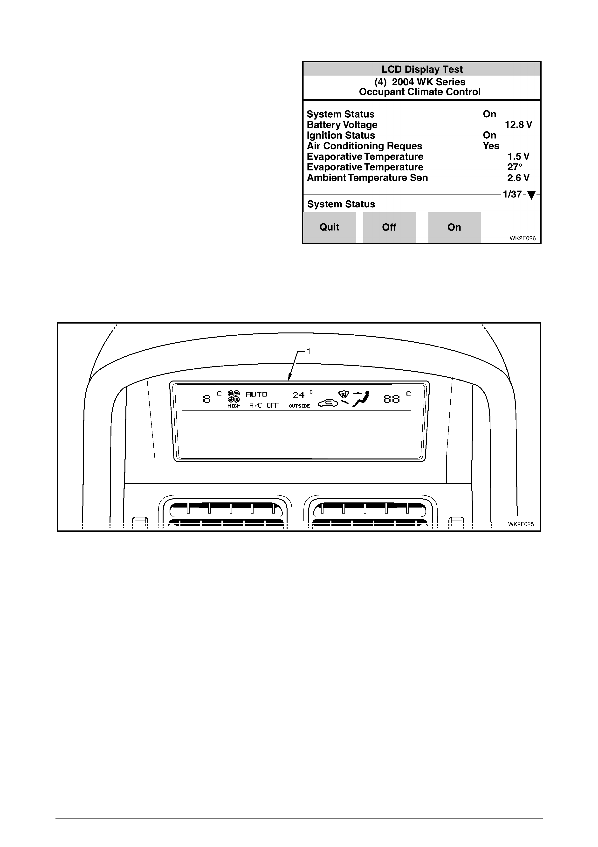
HVAC LCD Display Test
To ensure that all HVAC related segments are functioning
correctly and are properly displayed on the MFD screen, a
further test can be carried out through the Occupant Climate
Control menu of TECH 2.
PRE-CONDITION:
Engine not running.
PROCEDURE:
With TECH 2 connected to the DLC select:
Body /
Occupant Climate Control /
Miscellaneous Tests /
LCD Display Test.
Figure 12I – 43
Using the On/Off soft keys on TECH 2, activate and deactivate the upper section of the Multi Function Display. The MFD
should display upper screen detail identical to that shown in Figure 12I – 44. All segments should appear for
approximately 5 seconds after the On soft key is activated.
Figure 12I – 44
Multi Function Display Page 12I–32
Page 12I–32
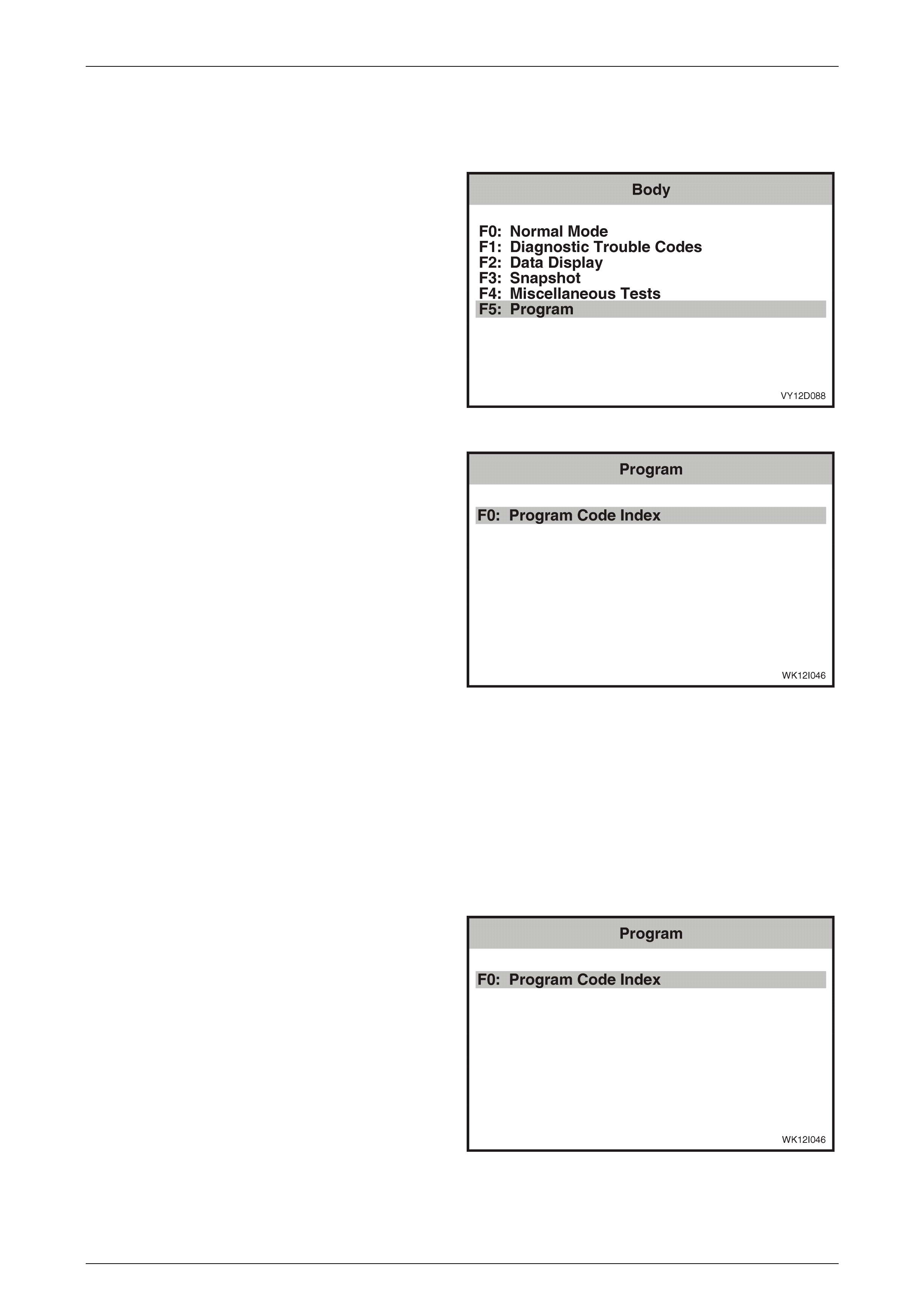
3.7 Program
The Program function allows the MFD time display to be changed from a 24 hour clock to a 12 hour clock.
1 From the Body Menu select F5: Program and press
the Enter key.
Figure 12I – 45
2 Scroll through the Program list using the TECH 2 Up
and Down arrows. To select the required item, press
the Enter key.
Figure 12I – 46
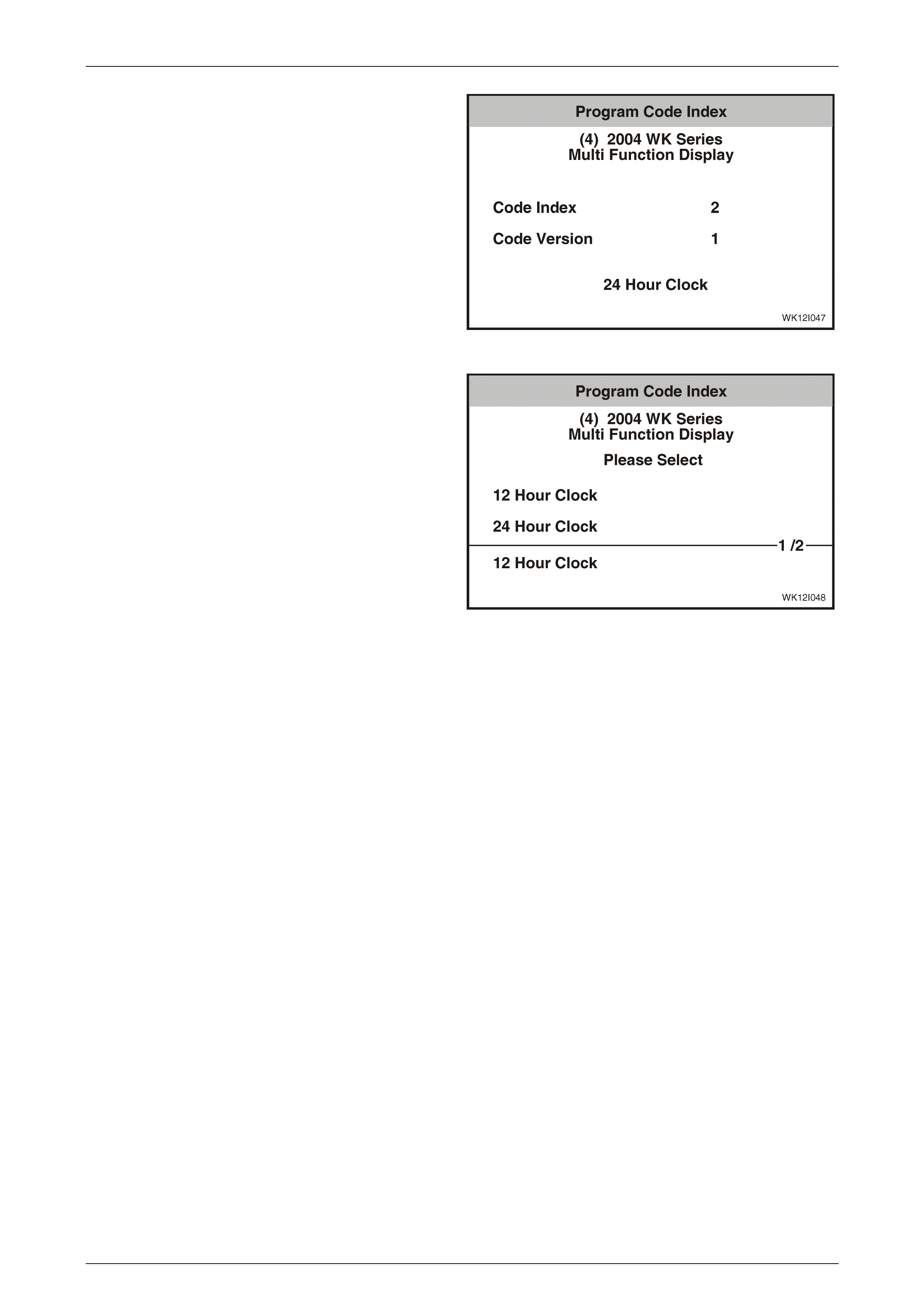
F0: Program Code Index
The Code Index number identifies the MFD and vehicle configuration, and the Code Version number identifies the
software version. Only the Code Index number can be changed. The following table details the Code Index numbers for
the various models in the MY 2004 WK Series vehicles. The following code indexes are available:
1 12 Hour Clock
2 24 Hour clock
1 From the Program Menu select F0: Program Code
Index and press the Enter key.
Figure 12I – 47
Multi Function Display Page 12I–33
Page 12I–33
2 Press the Modify soft key on the TECH 2 to modify the
Code Version. Press the Okay soft key to retain the
current setting.
Figure 12I – 48
3 Use the up and down arrow keys on the TECH 2 to
scroll to the desired clock setting. To program the
selection, press the Program soft key on the TECH 2.
If you do not wish to program a clock setting, press the
Abort soft key on the TECH 2 to exit the menu.
Figure 12I – 49

Multi Function Display Page 12I–34
Page 12I–34
3.8 Multi Function Display Diagnostic
Procedures
General Diagnostics
The MY 2004 WK Series MFD displays information from the radio and the OCC. If the values displayed on the MFD are
incorrect, the most likely source of the fault lies with either the AHU or the OCC.
Audio information is communicated to the MFD via the UART Class 2 bus. This bus is new to WK Series vehicles. The
UART Class 2 bus can be diagnosed using the TECH2.
OCC information is communicated to the MFD via a dedicated CAN bus. The CAN communications between the OCC
and MFD is one way, with the OCC sending information and the MFD receiving it.
With the ignition in the Off position, the MFD draws power directly from the battery. In this mode, the MFD only displays
time and date information. With the ignition in the On position, the MFD displays Audio and OCC information (if the OCC
is turned on). These functions are powered through the accessory control relay within X129. When the park lamps are
on, the illumination of the MFD is controlled through the park lamps control relay within X129. The illumination can be
adjusted using the variable intensity illumination control slider on the headlamp switch. If the illumination is set to 0%, the
MFD screen will be blank while the headlamps are on. When the ignition is On and the park lamps are off, the MFD is at
maximum illumination.

Multi Function Display Page 12I–35
Page 12I–35
MFD Diagnostic Circuit Check Diagnostic Chart
Step Action Value(s) Yes No
1 Turn the ignition off and the park lamps off.
Does MFD display time and date?
Go to Step 2. Refer to
MFD No Power
Diagnostic Chart
in this Section for
further diagnosis.
2 Turn the ignition On.
Does MFD Illumination backlighting come on?
Go to Step 3. Refer to
No Illumination or
No Dimming Control
Diagnostic Chart
in this Section for
further diagnosis.
3 With the Ignition On turn the audio system on.
Does the audio system power up?
Go to Step 4. Go to
Section 12D, 3.12
Audio System
Diagnostic
Procedures
in this Service
Information.
4 Does MFD display all audio information? Go to Step 5. Go to
No Audio
Information
Displayed
in this Section for
further diagnosis.
5 Turn on the OCC blower fan.
Does the blower fan operate?
Go to Step 6. Go to
Section 2F HVAC
Occupant Climate
Control (Auto A/C) –
Diagnostics
in this Service
Information.
6 Turn off the OCC blower fan.
Does the MFD display all OCC information?
Go to Step 7. Refer to
DTC – No CAN
communication from
OCC System
Diagnostics Table
in this Section for
further diagnosis.
7 Connect TECH 2 to the DLC.
On TECH 2 select Diagnostics / Model Year / Vehicle
Model / Body / Multi Function Display / Diagnostic
Trouble Codes / Read Diagnostic Trouble Codes.
Are any current DTCs set?
Refer to relevant
DTC diagnostic
table in this Section.
Go to Step 8.
8 Are there any history DTCs set? Go to Step 9. System OK.
9 Clear DTCs from TECH 2.
In TECH 2 Select Read Diagnostic Trouble Codes.
Are any current DTCs set?
Refer to relevant
DTC diagnostic
table in this Section.
Refer to
Section 12P Wiring
Diagrams,
4.7 Detecting
Intermittent
Electrical Faults
in the MY 2003 VY
and V2 Series
Service Information.
WHEN ALL DIAGNOSIS AND REPAIRS ARE COMPLETED, VERIFY CORRECT OPERATION

Multi Function Display Page 12I–36
Page 12I–36
MFD No Power
The MFD is permanently powered through Fuse 21 at any position of the ignition switch. In the off position, the time and
date will still be displayed but the display will not be illuminated. When the key is turned to the accessories or ignition
position and the audio and OCC (Auto A/C) systems are off, the time and date will continue to be displayed and the
display will be illuminated. Accessory power to the MFD is supplied through Fuse 16 via the accessory control relay. The
accessory control relay is switched on by the BCM when the key is turned to the accessory position.
MFD No Power Diagnostic Chart
Step Action Value(s) Yes No
1 Has the MFD Diagnostic Circuit Check been
performed?
Go to Step 2. Perform
MFD Diagnostic
Circuit Check
as described in this
Section.
2 Turn the ignition Off.
Remove the MFD. Refer to 2.1 Multi Function Display,
Remove in this Section.
Using a digital voltmeter, measure the voltage between
MFD connector P5 terminal X1-11, circuit 1340 and a
known good ground.
Is the voltage as specified?
12.5 V Go to Step 3. No battery power to
MFD. Check fuses
F21 and F105 and
circuits 1340 and
342. Replace fuse
or repair circuit as
necessary.
3 Using a digital Ohmmeter, measure the resistance
between MFD connector P5 terminal X1-10, circuit 251
and a known good ground.
Is the value as specified?
Open Circuit Repair open in
circuit 251 and
check wiring and
ground connections
at location X157
(right hand inner
fender panel).
Replace MFD.
Refer to
2.1 Multi Function
Display
in this Service
Information.
WHEN ALL DIAGNOSIS AND REPAIRS ARE COMPLETED, VERIFY CORRECT OPERATION

Multi Function Display Page 12I–37
Page 12I–37
No Illumination or No Dimming Control
When the park lamps are on, reduced illumination of the MFD is controlled through the park lamps control relay within X129 at terminal
X1–3 of the MFD. The illumination can be adjusted using the variable intensity illumination control slider on the headlamp switch. The
selected setting is sent to the BCM and forwarded to the OCC control module. The OCC control module passes this message to the
MFD via the CAN bus communications linking the two modules. If the illumination is set to 0%, the MFD screen will be blank while the
headlamps are on. When the ignition is on and the park lamps are off, the MFD is at maximum illumination.
No Illumination or No Dimming Control Diagnostic Chart
Step Action Value(s) Yes No
1 Has the MFD diagnostic circuit check been performed? Go to Step 2. Perform
MFD diagnostic
circuit check
as described in this
Section.
2 Turn ignition On.
Turn park lamps On.
Adjust the illumination using the variable intensity
illumination control slider on the headlamp switch.
Does the MFD illumination respond to changes in
dimming level?
System OK. Go to Step 3.
3 Turn ignition On.
Turn park lamps On.
Adjust the illumination using the variable intensity
illumination control slider on the headlamp switch.
Does the instrument cluster illumination respond to
changes in dimming level?
Go to Step 4. Refer to
Section 12J,
4.14 Instrument
Dimming Control
in the MY 2003 VY
and V2 Series
Service Information.
4 Turn the ignition Off.
Turn the park lamps Off.
Remove the MFD. Refer to 2.1 Multi Function Display,
Remove in this Section.
Turn the ignition On.
Turn the park lamps On.
Using a digital voltmeter, check the voltage between the
MFD connector P5, terminal X1-3, circuit 32 and a
known good ground.
Is the voltage as specified?
12.5 V Replace MFD.
Refer to
2.1 Multi Function
Display
in this Section.
Go to Step 5.
5 Turn the ignition Off.
Turn the park lamps Off.
Using a digital ohmmeter, check for continuity between
the MFD connector P5, terminal X1-3 and Park Lamps
Control Relay XC129, terminal X32-5, circuits 32 and 9.
Is the value as specified?
Less than 1
ohm.
Go to Step 6. Repair open in
circuit 32. Check for
blown fuse F11.
6 Turn the ignition Off.
Turn the park lamps Off.
Using a digital ohmmeter, check the resistance between
the MFD connector P5, terminal X1-3, circuit 32 and a
known good ground.
Is the value as specified?
Open Circuit,
no continuity.
Check all system
wiring harness
connectors and
terminal retention.
Refit all components
and recheck
operation.
Repair short to
ground in circuit 43.
WHEN ALL DIAGNOSIS AND REPAIRS ARE COMPLETED, VERIFY CORRECT OPERATION

Multi Function Display Page 12I–38
Page 12I–38
No Audio Informati on Displayed
A failure to display radio information on the MFD can be caused by any of the following conditions:
• Faulty audio head unit
• Faulty MFD
• Installation of a foreign or lower level audio system
• Loss of power to the MFD
• Loss of serial communication between the MFD and the audio system
The following diagnostic chart determines which of the above conditions has caused the fault and provides directions for
further diagnosis of the problem.
No Radio Information Displayed Diagnostic Chart
Step Action Value(s) Yes No
1 Has the MFD Diagnostic Circuit Check been
performed?
Go to Step 2. Perform MFD
diagnostic circuit
check as described
in this Section.
2 Turn the ignition On.
Connect TECH 2 to the DLC.
On TECH 2 select Diagnostics / Model Year / Vehicle
Model / Body / Audio System.
Does TECH 2 display audio system identification data?
Go to Step 3. Go to
Section 12D, 3.12
Audio System
Diagnostic
Procedures
in this Service
Information.
3 On TECH 2 select Diagnostics / Model Year / Vehicle
Model / Body / Multi Function Display.
Does TECH 2 display MFD system identification data?
Go to Step 4. Go to Step 6.
4 On TECH 2 select Diagnostics / Model Year / Vehicle
Model / Body / Audio System / Data Display / System
Identification.
Find the audio system identifier number.
Is the identifier number one of the values specified?
306
311
411
601
Go to Step 5. Remove AHU and
replace with a WK
Series AHU.
Refer to
Section 12D
Entertainment
System
in this Service
Information.
5 On TECH 2 select Diagnostics / Model Year / Vehicle
Model / Body / Multi Function Display / Miscellaneous
Tests / Display / All Segments.
Perform the all segments illumination test. Refer to
3.6 Miscellaneous Tests, F1: All Segments in this
Section.
Does the MFD display illuminate all segments?
Refer to
DTC No Serial Data
From Audio System
Diagnostic Chart
in this Section for
further diagnosis
Replace MFD.
Refer to
2.1 Multi Function
Display
in this Section.
6 Turn the ignition Off.
Remove the MFD. Refer to 2.1 Multi Function Display,
Remove in this Section.
Turn the ignition to the Accessories position.
Using a digital voltmeter, measure the voltage between
MFD connector P5 terminal X1-12, circuit 43 and a
known good ground.
Is the voltage as specified?
12.5 V Refer to
DTC No Serial Data
From Audio System
Diagnostic Chart
in this Section for
further diagnosis
Go to Step 7.

Multi Function Display Page 12I–39
Page 12I–39
Step Action Value(s) Yes No
7 Check Fuse F16, and circuits 43 and 70.
Is fuse F16 and circuits 43 and 70 OK?
Refer to
Section 12J Body
Control Module,
4.4 Accessory
Power Control
in the MY 2003 VY
and V2 Series
Service Information
for further diagnosis.
Repair fault in
circuits 43 or 70 or
replace fuse F16.
8 Using a digital ohmmeter, measure the resistance
between MFD connector P5 terminal X1-10, circuit 251
and a known good ground.
Is the value as specified?
Less than
1 Ohm.
Replace MFD.
Refer to
2.1 Multi Function
Display
in this Service
Information.
Repair open in
circuit 251 and
check wiring and
ground connections
at location X157
(right-hand inner
fender panel).
WHEN ALL DIAGNOSIS AND REPAIRS ARE COMPLETED, VERIFY CORRECT OPERATION

Multi Function Display Page 12I–40
Page 12I–40
DTC – No Serial Data From Audio S ystem
With the ignition in either the accessories or on position, this DTC will set if the MFD does not receive serial data from the
Audio System for more than 10 seconds.
No Serial Data From Audio Sys tem Diagnostic Chart
Step Action Value(s) Yes No
1 Has the MFD Diagnostic Circuit Check been
performed?
Go to Step 2. Perform MFD
diagnostic circuit
check as described
in this Section.
2 Turn Ignition On.
Turn Radio On.
Connect TECH 2 to the DLC.
On TECH 2 select Diagnostics / Model Year / Vehicle
Model / Body / Audio System.
Does TECH 2 display Audio System Information?
Go to Step 3. Go to Audio System
Diagnostics in
Section 12D
Entertainment
System
in this Service
Information.
3 On TECH 2 select Diagnostics / Model Year / Vehicle
Model / Body / Audio System / Miscellaneous Tests /
Display.
Press the On soft key on TECH 2.
Do all the segments on the lower half of the MFD
illuminate?
Go to Step 7. Go to Step 4.
4 Turn the ignition OFF.
Remove the MFD. Refer to 2.1 Multi Function Display in
this Section.
Reinstall the AHU.
Disconnect TECH 2 from the DLC.
Turn the ignition to Accessories position.
Using a digital voltmeter check the voltage between
MFD connector P5, terminal X1-4, circuit 377 and a
known good ground.
Is the voltage as specified?
Approx 2-4 V Replace the MFD.
Refer to
2.1 Multi Function
Display
in this Section.
Go to Step 5.
5 Turn the ignition Off.
Remove the AHU.
Using a digital ohmmeter, check for continuity between
MFD connector P5, terminal X1-4 and audio unit
connector A133, terminal X1-C14, circuit 377.
Is the value as specified?
Less than
1 Ohm.
Go to Step 6. Repair open in
circuit 377.
6 Turn the ignition Off.
Using a digital ohmmeter, check the resistance between
MFD connector P5, Terminal X1-4, circuit 377 and a
known good ground.
Is the value as specified?
Open circuit,
no continuity.
Replace AHU.
Refer to
Section 12D,
2.1 Audio System
Head Unit
in this Service
Information.
Repair short to
ground in circuit
377.
7 Turn Ignition Off.
Using a digital ohmmeter, check the voltage at data link
connector X40, terminal X1-1, circuit 377.
Is the voltage at the specified value?
2-4 V. Go to Step 11. Go to Step 8.

Multi Function Display Page 12I–41
Page 12I–41
Step Action Value(s) Yes No
8 Was the voltage at step 7 above the specified value? 2-4 V. Go to Step 9. Go to Step 10.
9 Remove audio head unit. Refer to Section 12D
Entertainment System, 2.1 Audio System Head Unit in
this Service Information.
Using a digital ohmmeter, check the voltage at
connector X40, terminal X1-1, circuit 377.
Is the voltage above the specified value?
2-4 V. Repair short to
voltage in circuit
377.
Replace AHU.
Refer to
Section 12D,
2.1 Audio System
Head Unit
in this Service
Information.
10 Remove audio head unit. Refer to Section 12D,
2.1 Audio System Head Unit in this Service Information.
Using a digital ohmmeter, check the voltage at
connector X40, terminal X1-1, circuit 377.
Is the voltage below the specified value?
2-4 V. Repair short to
ground in circuit
377.
Replace Radio.
Refer to
Section 12D,
2.1 Audio System
Head Unit
in this Service
Information.
11 Turn ignition On.
Connect TECH 2 to the DLC.
On TECH 2 Select Diagnostics / Model Year / Vehicle
Model / Body / MFD / Diagnostic Trouble Codes / Read
DTC Information.
Is the a history DTC – No Serial Data from Audio
System set?
Go to Audio
diagnostics. Refer to
Section 12D
Entertainment
System
in this Service
Information.
Go to Step 12.
12 Perform an intermittent electrical fault test. Refer to
Section 12P Wiring Diagram, 4.7 Detecting Intermittent
Electrical Faults in the MY 2003 VY and V2 Series
service Information. Test the following connectors and
circuits:
• Circuit 377.
• Connector P5-X1.
• Connector X40-X1.
• Connector A133-X1
Was an intermittent fault detected in one of the
connectors or circuits?
Repair faulty circuit
or connector.
System OK.
WHEN ALL DIAGNOSIS AND REPAIRS ARE COMPLETED, VERIFY CORRECT OPERATION

Multi Function Display Page 12I–42
Page 12I–42
DTC – No CAN Communication From OCC System
With the ignition in either the accessories or on position, this DTC will set if the MFD does not receive CAN
communications for more than 10 seconds.
No CAN Communication From OCC System Diagnostic Table
Step Action Value(s) Yes No
1 Has the MFD Diagnostic Circuit Check been
performed?
Go to Step 2. Perform MFD
diagnostic circuit
check as described
in this Section.
2 Turn the Ignition On.
Connect TECH 2 to the DLC.
On TECH 2 select Diagnostics / Model Year / Vehicle
Model / Body / Multi Function Display
Does TECH 2 display MFD Information?
Go to Step 3. Refer to
DTC No Serial Data
From Audio System
Diagnostic Chart
in this Section for
further diagnosis.
3 Turn Ignition On.
Turn OCC On.
Connect TECH 2 to the DLC.
On TECH 2 select Diagnostics / Model Year / Vehicle
Model / Body / Occupant Climate Control.
Does TECH 2 display OCC Information?
Go to Step 4. Go to OCC System
Diagnostics.
Refer to
Section 2F HVAC
Occupant Climate
Control (Auto A/C) –
Diagnostics
in this Service
Information.
4 On TECH 2 select / Body / Multi Function Display /
Miscellaneous Tests / Display / All Segments.
Perform the all segments illumination test. Refer to
3.6 Miscellaneous Tests F1: All Segments in this
Section.
Does the MFD display illuminate all segments?
Go to Step 5. Replace MFD.
Refer to
2.1 Multi Function
Display
in this Section.
5 Turn the ignition Off.
Remove the MFD. Refer to 2.1 Multi Function Display,
Remove in this Section.
Remove the OCC controller from the centre trim
assembly. Refer to Section 2E Occupant Climate
Control (Auto A/C) – Removal and Installation in this
Service Information.
Reconnect the two OCC wiring harness connectors to
the rear of the OCC control module.
Turn the Ignition On.
Using a digital voltmeter, measure the voltage between
MFD connector P5, terminal X1-1, circuit 5169 and a
known good ground.
Is the voltage as specified?
Approx 2.5 V Go to Step 8. Go to Step 6.
6 Using a digital ohmmeter, measure the resistance
between MFD connector P5, terminal X1-1, circuit 5169
and a known good ground.
Is the value as specified?
Open circuit,
no continuity
Repair open in
circuit 5169.
Go to Step 7.
7 Using a digital ohmmeter, measure the resistance
between MFD connector P5, terminal X1-1, circuit 5169
and a known good ground.
Is the value as specified?
Short circuit
to ground.
Repair short to
ground in circuit
5169.
Go to Step 11

Multi Function Display Page 12I–43
Page 12I–43
Step Action Value(s) Yes No
8 Turn the ignition to the On position.
Using a digital voltmeter, measure the voltage between
a MFD connector P5, terminal X1-7, circuit 5170 and a
known good ground.
Is the value as specified?
Approx 2.5 V Replace MFD
module. Refer to
2.1 Multi Function
Display
in this Section.
Go to Step 9.
9 Disconnect wiring harness connectors from the OCC
controller.
Using a digital ohmmeter, check for continuity between
MFD connector P5, terminal X1-7 and OCC controller
connector A14m terminal X1-9, circuit 5170.
Is the value as specified?
Less than
1 Ohm.
Go to Step 10. Repair circuit 5170.
10 Using a digital ohmmeter, measure the resistance
between MFD connector P5, terminal X1-7, circuit 5170
and a known good ground.
Is the value as specified?
Open circuit,
no continuity.
Go to Step 11. Repair circuit 5170.
11 Turn ignition On.
Replace the OCC control module with a known good
module. Refer to Section 2E Occupant Climate Control
(Auto A/C) – Remove and Install in this Service
Information.
Connect TECH 2 to the DLC.
On TECH 2 select Diagnostics / Model Year / Vehicle
Model / Body / Occupant Climate Control /
Miscellaneous Tests / LCD Display Test.
Were all the segments on the top half of the MFD
displayed?
System OK. Remove
replacement OCC
controller and install
the original OCC
controller. Refer to
Section 2E
Occupant Climate
Control (Auto A/C) –
Removal and
Installation
in this Service
Information.
Replace the MFD.
Refer to
2.1 Multi Function
Display
in this Section.
WHEN ALL DIAGNOSIS AND REPAIRS ARE COMPLETED, VERIFY CORRECT OPERATION
Multi Function Display Page 12I–44
Page 12I–44
DTC – EEPROM Error
The EEPROM (Expandable Erasable Program, Read Only Memory) functions are carried out by the printed circuit
board (1) installed into the rear housing (2) of the Multi Function Display module. If this DTC has set, replace the MFD.
Figure 12I – 50

Multi Function Display Page 12I–45
Page 12I–45
4 Wiring Diagrams
The following figures provide electrical connector diagrams and a complete wiring diagram applicable to the Multi
Function Display as fitted to Level 2 to 5 MY 2004 WK Series vehicles. These diagrams should be used as an aid to
diagnosing circuit faults. The content of these figures is as follows:
• Electrical connectors (A14 – S125) – refer to Figure 12I – 51
• Electrical connectors continued (X40 – X129) – refer to Figure 12I – 52
• Wiring diagram – refer to Figure 12I – 53
For wiring diagrams related to the Occupant Climate Control (Auto A/C) system as fitted to Level 2 to 5 MY 2004
WK Series vehicles, refer to Section 2F, 4 Wiring Diagrams.
In the following wiring diagram (Figure 12I – 53) all components are described and displayed in accordance to the
Integrated Vehicle Electrical Design (IVED) standard as applied to MY 2004 WK Series vehicles. To assist in wiring
diagram interpretation, refer to the following table:
IVED Description IVED Component Identification Common Description
Module Asm Blo & A/C Cmpr A14 OCC Control Module
Module Asm Body Cont A15 Body Control Module
Radio Asm AM / FM Stereo & Clk &
Cd Plyr
A133 Radio, CD Player / Audio Head Unit
(AHU)
Display Asm, Amb Air Temperature
Ga & Rdo & Clk & Date
P5 Multi Function Display (MFD)
Switch Asm Hdlp Auto Cont S125 Headlamp Switch
The following table lists the IVED standard wire colour abbreviations:
BK Black D-GN Dark green L-GN Light green RD Red
BU Blue GN Green OG Orange TN Tan
BN Brown GY Grey PK Pink WH White
D-BU Dark blue L-BU Light blue PU Purple YE Yellow
NOTE
For electrical connector locations and
additional wiring diagram information refer to
Section 12P Wiring Diagrams in this Service
information.
Multi Function Display Page 12I–46
Page 12I–46
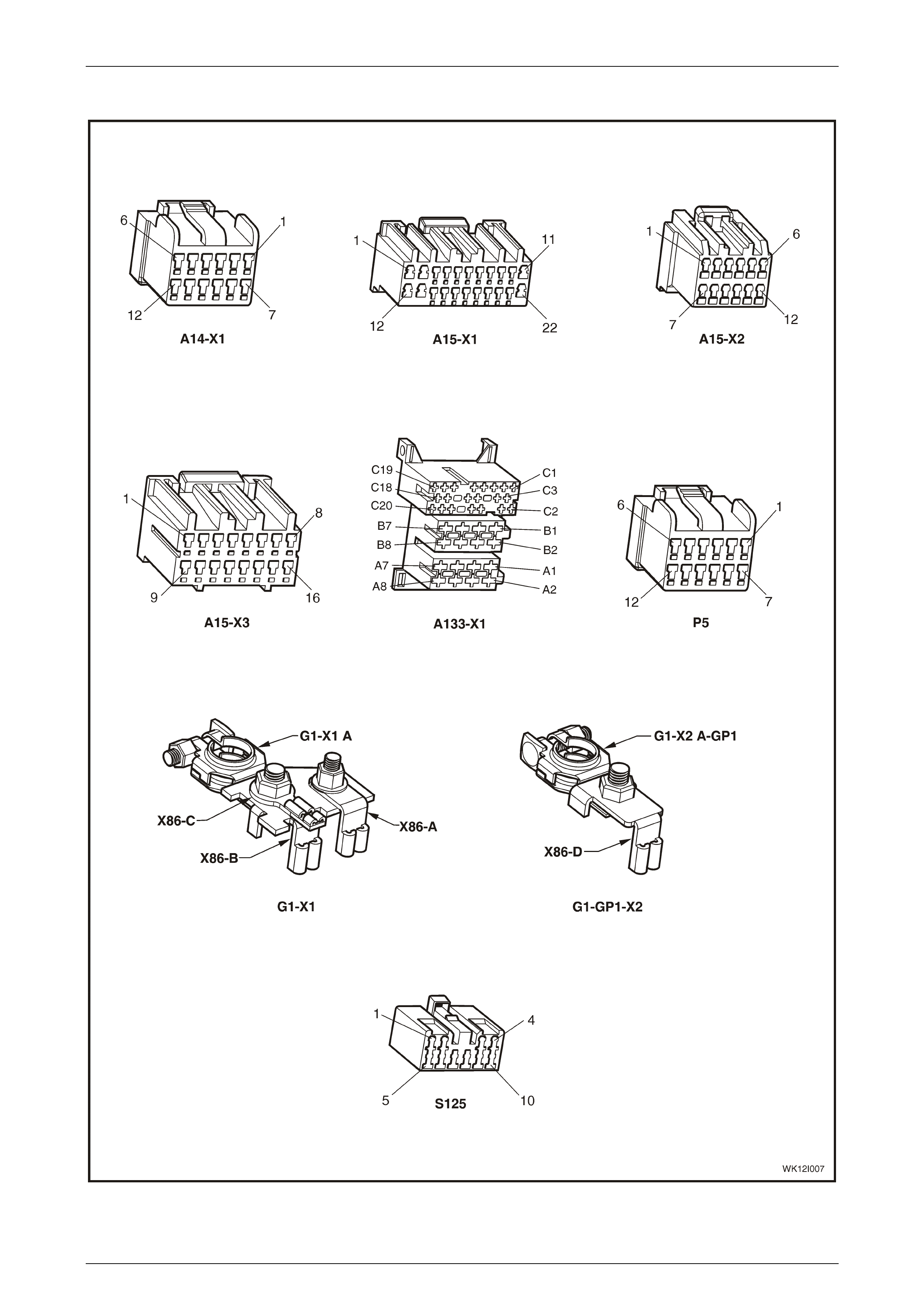
Connectors (A14 – S125)
Figure 12I – 51
Multi Function Display Page 12I–47
Page 12I–47
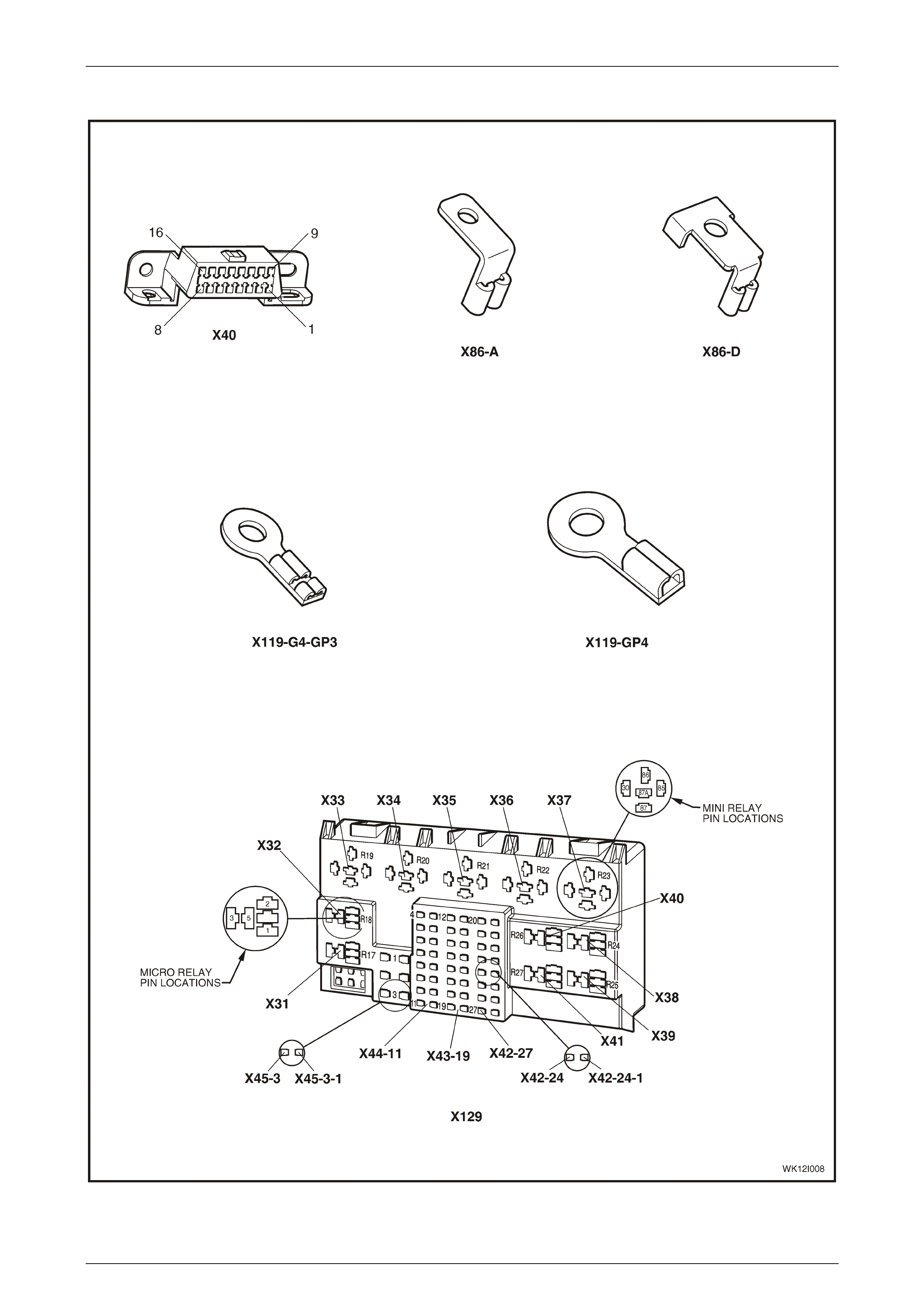
Connectors continued (X40 – X129)
Figure 12I – 52
Multi Function Display Page 12I–48
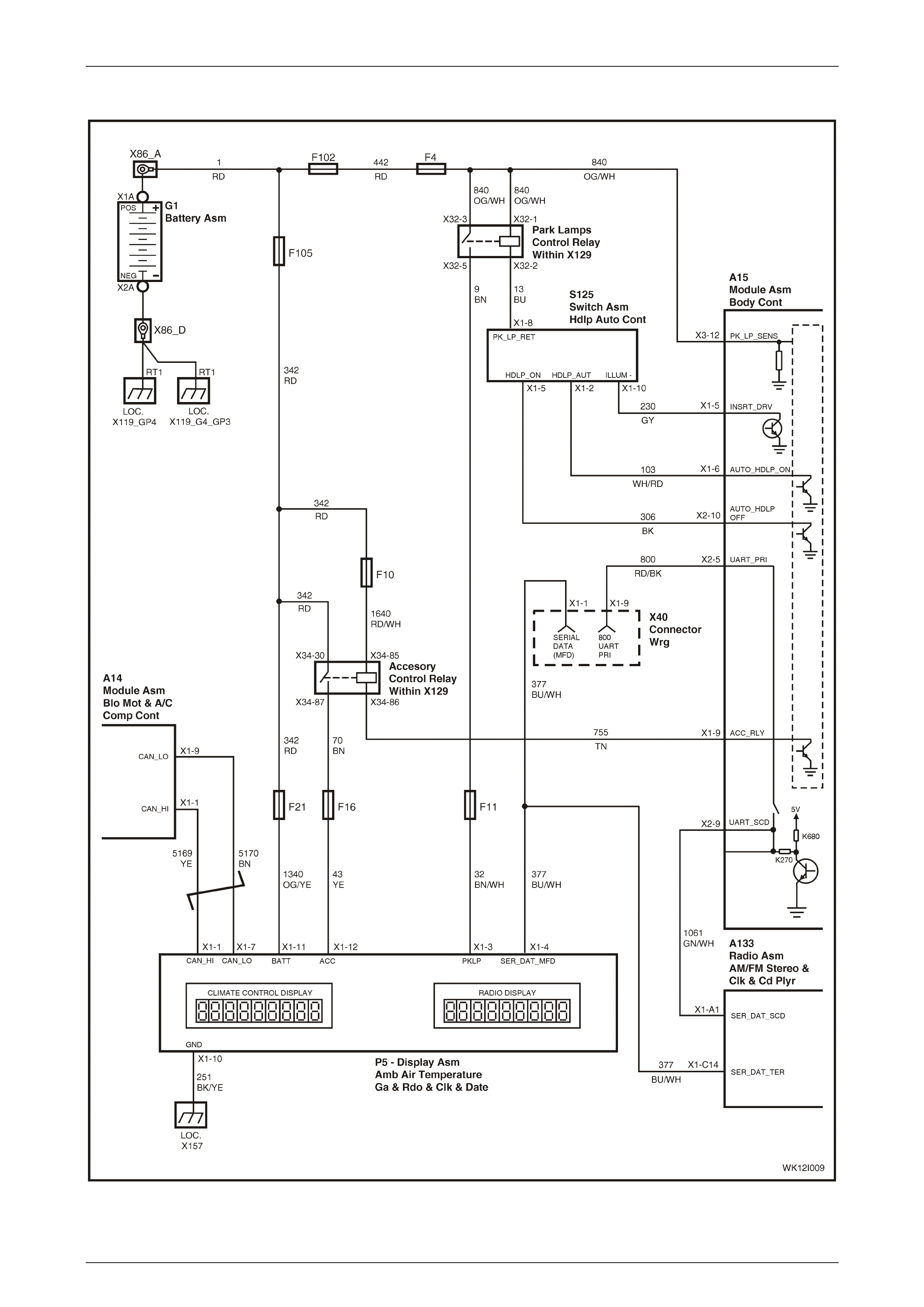
Page 12I–48
Wiring diagram: Multi Function Display
Figure 12I – 53

Multi Function Display Page 12I–49
Page 12I–49
5 Torque Wrench Specifications
Centre Air Outlet Housing Attaching Screw ...................................1.0 – 3.0 Nm
Floor Console Cover Assembly Attaching Screw...........................1.0 – 3.0 Nm
Instrument Panel Centre Trim Assembly Attaching Screw.............1.0 – 3.0 Nm
Instrument Cluster Trim Assembly Attaching Screw ......................1.0 – 3.0 Nm
MFD Attaching Screw ....................................................................1.0 – 3.0 Nm
Multi Function Display Page 12I–50
Page 12I–50
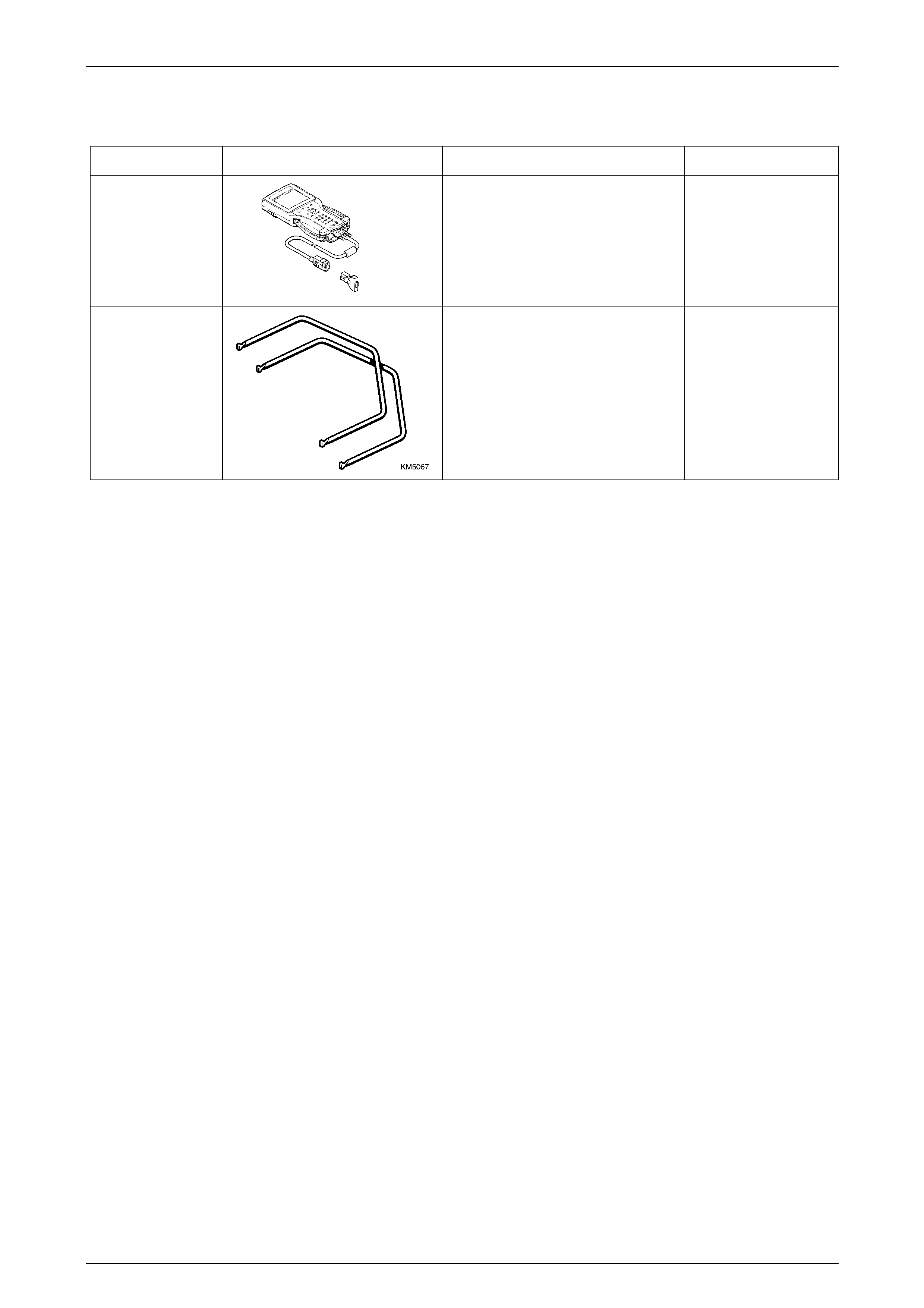
6 Special Tools
Tool Number Illustration Description Tool Classification
7000086I
TECH 2
Diagnostic Scan Tool
Used for diagnosis of vehicle electrical
system.
Previously released.
Mandatory
KM6067
Radio Removal Tool
Used for removing VY audio unit from
its mounting location.
New tool for VY.
Mandatory