
Telematics Page 12K–1
Page 12K–1
Section 12K
Telematics
ATTENTION
Before performing any service operation or other procedure described in this Section, refer to Section 00
Warnings, Cautions and Notes for correct workshop practices with regard to safety and/or property damage.
1 General Information............................................................................................................................... 3
2 Principles of Operation ......................................................................................................................... 4
2.1 Interior Rear View Mirror........................................................................................................................................5
Microphone.............................................................................................................................................................5
2.2 Audio System Interface .........................................................................................................................................6
2.3 Battery Voltage.......................................................................................................................................................7
2.4 Backup Battery Charger........................................................................................................................................8
2.5 Serial Data ...............................................................................................................................................................9
2.6 Driver's Door Ajar Switch ....................................................................................................................................11
2.7 Passenger Door Ajar Switches ...........................................................................................................................12
2.8 Alarm Input (Theft Deterrent Horn).....................................................................................................................13
2.9 Telematics Antenna .............................................................................................................................................14
2.10 Fuel Pump Relay Drive Circuit............................................................................................................................15
V6 Engine..............................................................................................................................................................15
V6 (Supercharged) Engine...................................................................................................................................16
GEN III V8 Engine.................................................................................................................................................16
3 Service Operations.............................................................................................................................. 17
4 TECH 2 Diagnosis for Telematics ...................................................................................................... 18
5 Diagnosis.............................................................................................................................................. 19
5.1 Telematics Module Terminal Descriptions.........................................................................................................21
5.2 Diagnostic Charts.................................................................................................................................................22
On-board Diagnostic System Check ..................................................................................................................22
DTC 1 — No Serial Data From BCM....................................................................................................................23
DTC 2 — No Serial Data From Instrument..........................................................................................................25
DTC 3 — No Serial Data From Sensing Diagnostic Module..............................................................................27
DTC 4 — No Serial Data From Audio System ....................................................................................................29
DTC 5 — No Serial Data.......................................................................................................................................31
DTC 9 — Vehicle Battery Voltage Too High.......................................................................................................33
DTC 10 — Vehicle Battery Voltage Too Low......................................................................................................34
DTC 13 — Backup Battery Timer Expired ..........................................................................................................35
DTC 14 — Backup Battery Voltage Too High.....................................................................................................36
DTC 15 — Backup Battery Voltage Too Low......................................................................................................37
DTC 16 — Backup Battery Not Detected............................................................................................................38
DTC 17 — Microphone Not Detected..................................................................................................................39
DTC 18 — Microphone Circuit Voltage Too Low...............................................................................................40
DTC 19 — Microphone Circuit Voltage Too High ..............................................................................................41
DTC 21 — Speaker Circuit Voltage Too Low......................................................................................................42
DTC 22 — Speaker Circuit Voltage Too High.....................................................................................................43
DTC 30 — Keypad Circuit Voltage Too High......................................................................................................44
Techline
Techline
Techline
Techline
Techline

Telematics Page 12K–2
Page 12K–2
DTC 42 — Fuel Pump Circuit Voltage Too Low.................................................................................................45
V6 Engine.........................................................................................................................................................45
V6 Supercharged Engine..................................................................................................................................45
GEN III V8 Engine............................................................................................................................................46
DTC 43 — Fuel Pump Circuit Voltage Too High ................................................................................................47
V6 Engine.........................................................................................................................................................47
V6 Supercharged Engine..................................................................................................................................47
GEN III V8 Engine............................................................................................................................................48
DTC 45 — End Call / Information Button Stuck.................................................................................................49
DTC 46 — Holden Assist Button Stuck..............................................................................................................51
DTC 47 — Emergency Button Stuck...................................................................................................................53
5.3 Symptoms Charts.................................................................................................................................................55
No Serial Data.......................................................................................................................................................56
Status Indicator LEDs Do Not Illuminate............................................................................................................57
Vehicle Battery Voltage .......................................................................................................................................58
Backup Battery.....................................................................................................................................................58
No GPS Signal......................................................................................................................................................59
No GSM Signal......................................................................................................................................................60
Emergency Button ...............................................................................................................................................61
Holden Assist Button...........................................................................................................................................62
End Call / Information Button..............................................................................................................................63
Theft Deterrent Horn............................................................................................................................................64
Driver's Door Ajar Switch ....................................................................................................................................64
Passenger Door Ajar Switches ...........................................................................................................................65
Microphone...........................................................................................................................................................66
Fuel Pump Relay Drive ........................................................................................................................................67
V6 Engine.........................................................................................................................................................67
V6 Supercharged Engine..................................................................................................................................67
GEN III V8 Engine............................................................................................................................................68
Audio Mute............................................................................................................................................................69
Audio System Interface .......................................................................................................................................70
Unable to Make or Receive a Call .......................................................................................................................71
Holden Assist Telematics System Test..............................................................................................................72
6 Torque Wrench Specifications........................................................................................................... 74

Telematics Page 12K–3
Page 12K–3
1 General Information
With the following exceptions, MY 2004 WK Series Te lematics information carries over from MY 2003 VY and V2 Series
vehicles:
• wiring diagrams (refer to 2 Principles of Operation and 5.2 Diagnostic Charts).
For all other Telematics general information, refer to Section 12K, 1 General Information in the MY 2003 VY and
V2 Series Service information.
NOTE
Refer to the relevant MY 2004 WK Series
Section for all external references contained
in the MY 2003 VY and V2 Series,
Section 12K Telematics. This is to verify that
there are no differences in the MY 2004
WK Series Service information that will affect the
service procedures referenced from MY 2003 VY
and V2 Series Service information.

Telematics Page 12K–4
Page 12K–4
2 Principles of Operation
Except for the following headings and accompanying text, illustrations and/or tables, MY 2004 WK Series Telematics
principles of operation information carries over from MY 2003 VY and V2 Series vehicles:
• Interior Rear View Mirror,
• Audio System Interface,
• Battery Voltage,
• Backup Battery Charger,
• Serial Data,
• Driver's Door Ajar Switch,
• Passenger Door Ajar Switches,
• Alarm Input (Theft Deterrent Horn),
• Telematics Antenna, and
• Fuel Pump Relay Drive Circuit.
For other principles of operation information not contained within this Section, refer to Section 12K Telematics in the
MY 2003 VY and V2 Series Service information.
NOTE
Refer to the relevant MY 2004 WK Series
Section for all external references contained
in the MY 2003 VY and V2 Series,
Section 12K Telematics. This is to verify that
there are no differences in the MY 2004
WK Series Service information that will affect the
service procedures referenced from MY 2003 VY
and V2 Series Service information.
Telematics Page 12K–5
Page 12K–5
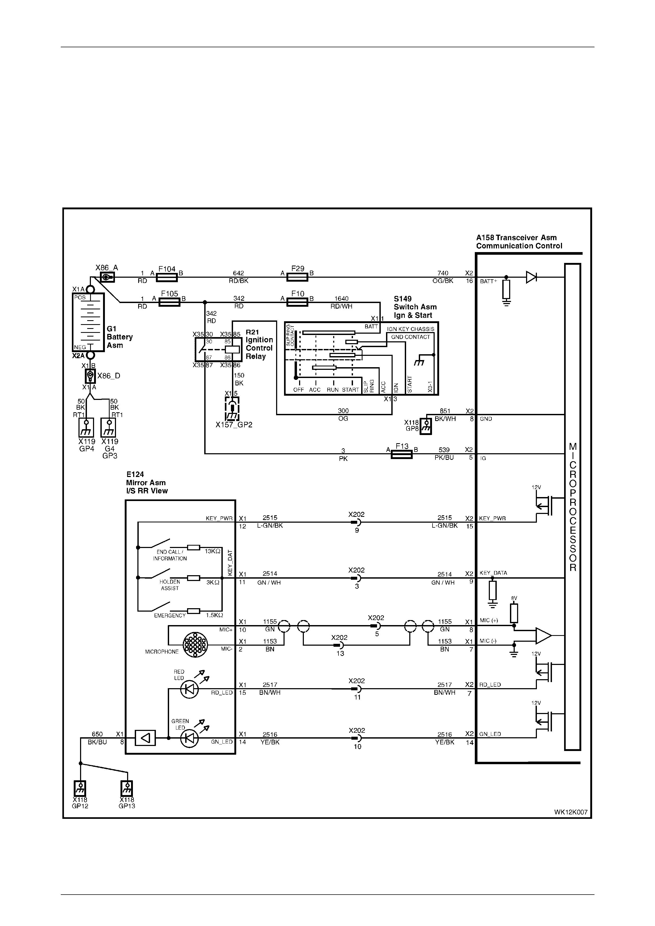
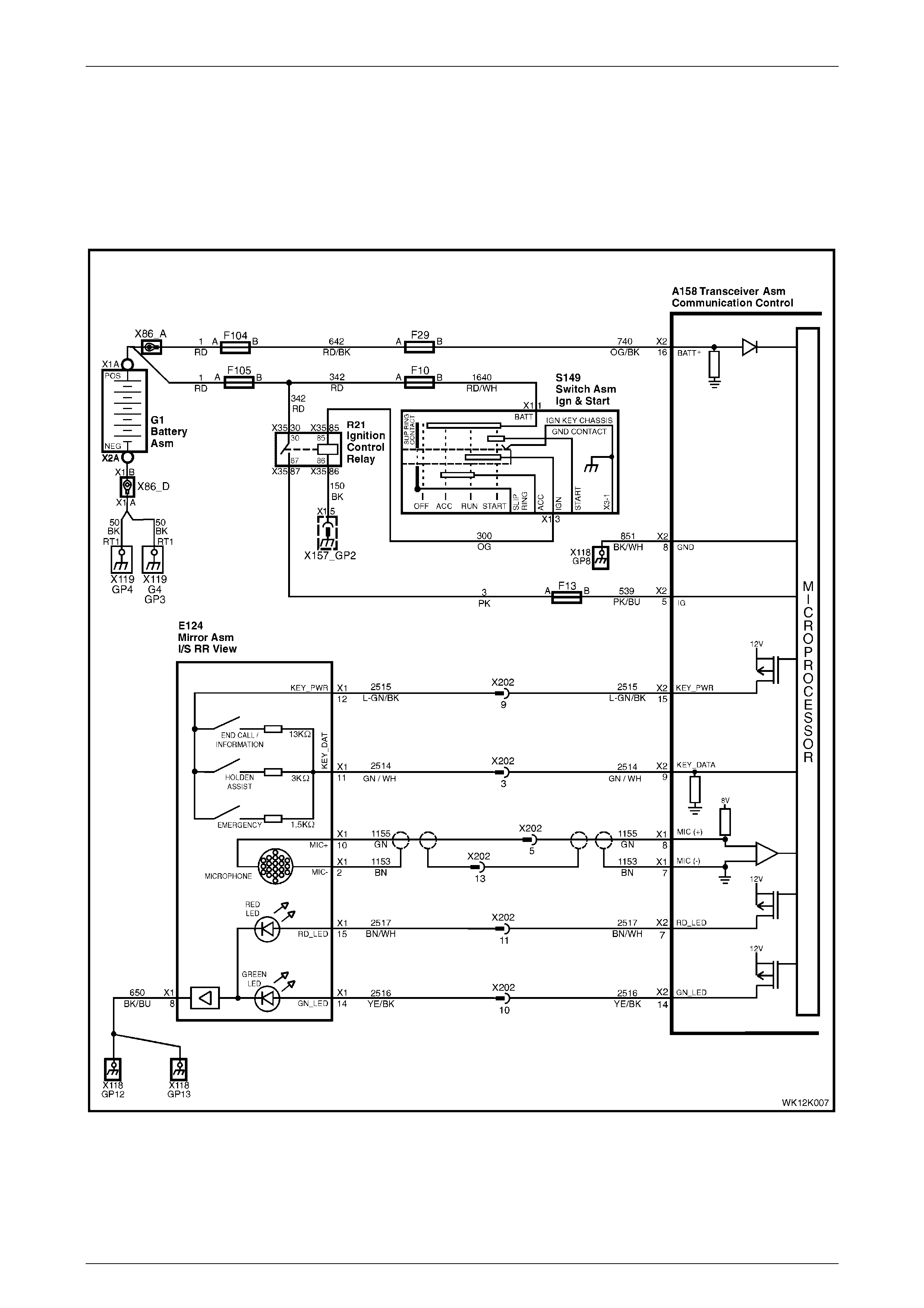
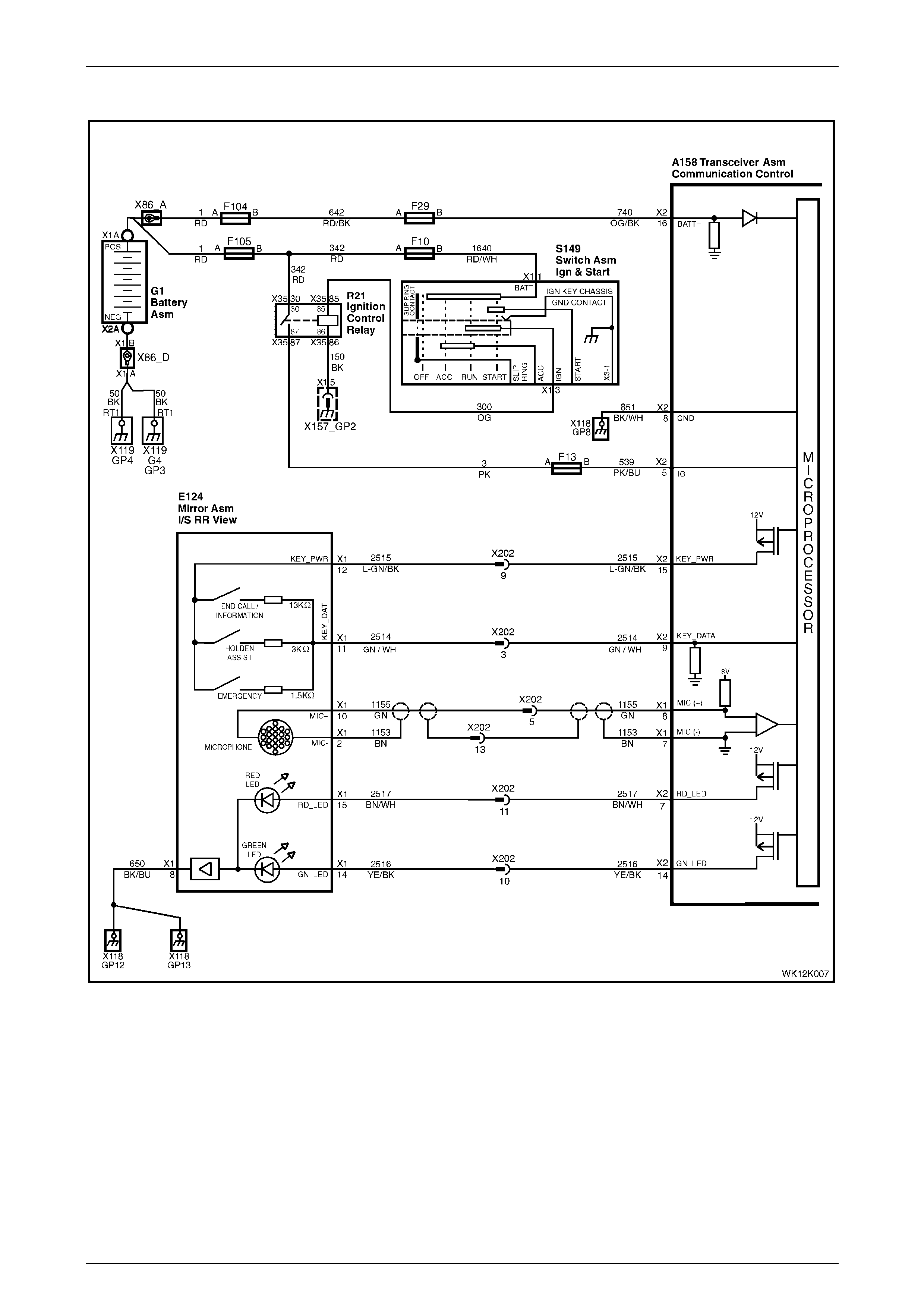
2.1 Interior Rear View Mirror
With the exception of the following text and wiring diagram, MY 2004 WK Series interior rear view mirror information
carries over from MY 2003 VY and V2 Series vehicles. For all other interior rear view mirror information, refer to
Section 12K, 2.5 Interior Rear View Mirror in the MY 2003 VY and V2 Series Service Information.
Microphone
The active microphone in the interior rear view mirror provides voice communication between the vehicle occupants and
the Holden Assist Centre.
Figure 12K – 1
Telematics Page 12K–6
Page 12K–6
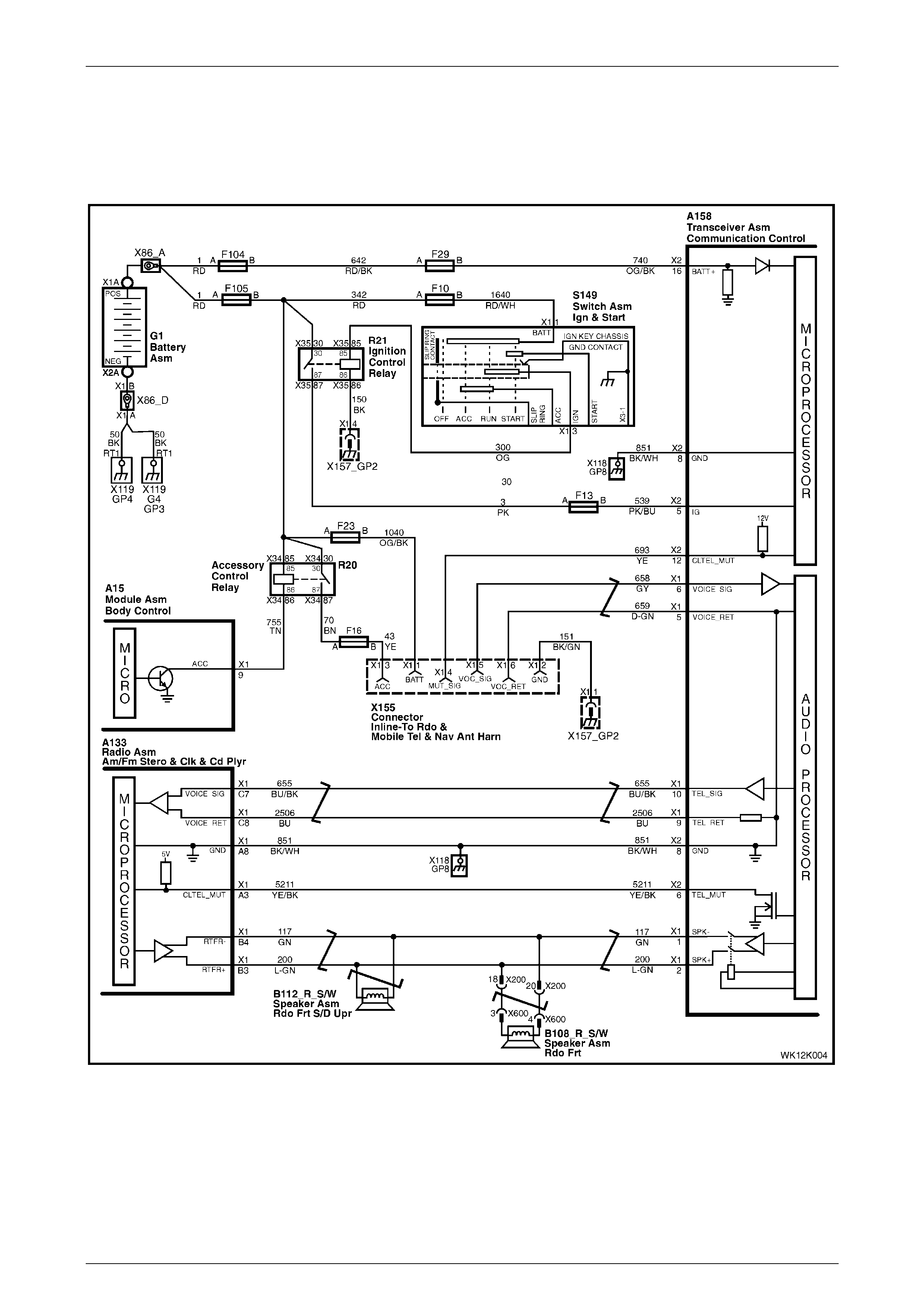
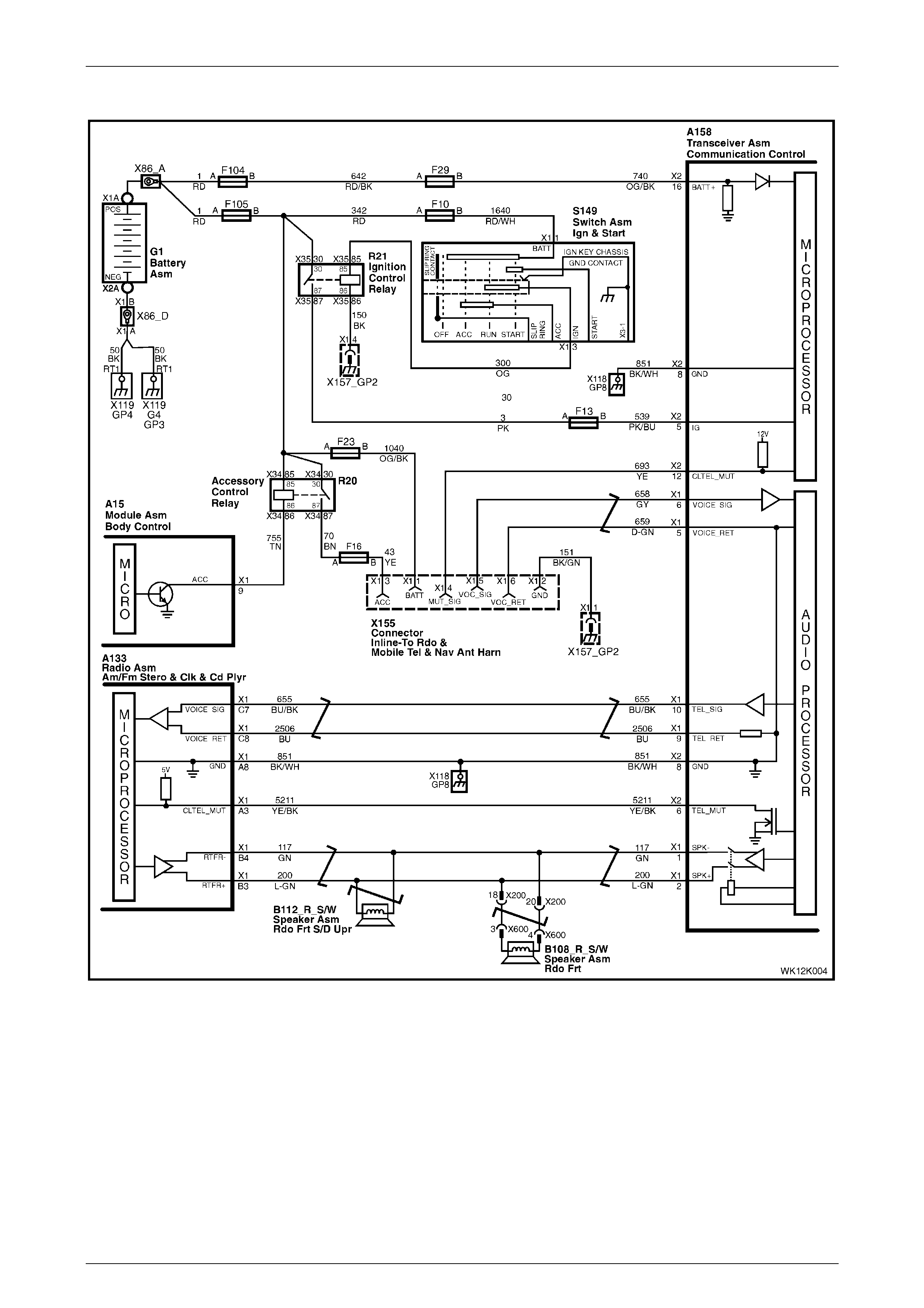
2.2 Audio System Interface
With the exception of the following wiring diagram, MY 2004 WK Series audio system interface information carries
over from MY 2003 VY and V2 Series vehicles. For all other audio system interface information, refer to
Section 12K, 2.6 Audio System Interface in the MY 2003 VY and V2 Series Service Information.
Figure 12K – 2
Telematics Page 12K–7
Page 12K–7
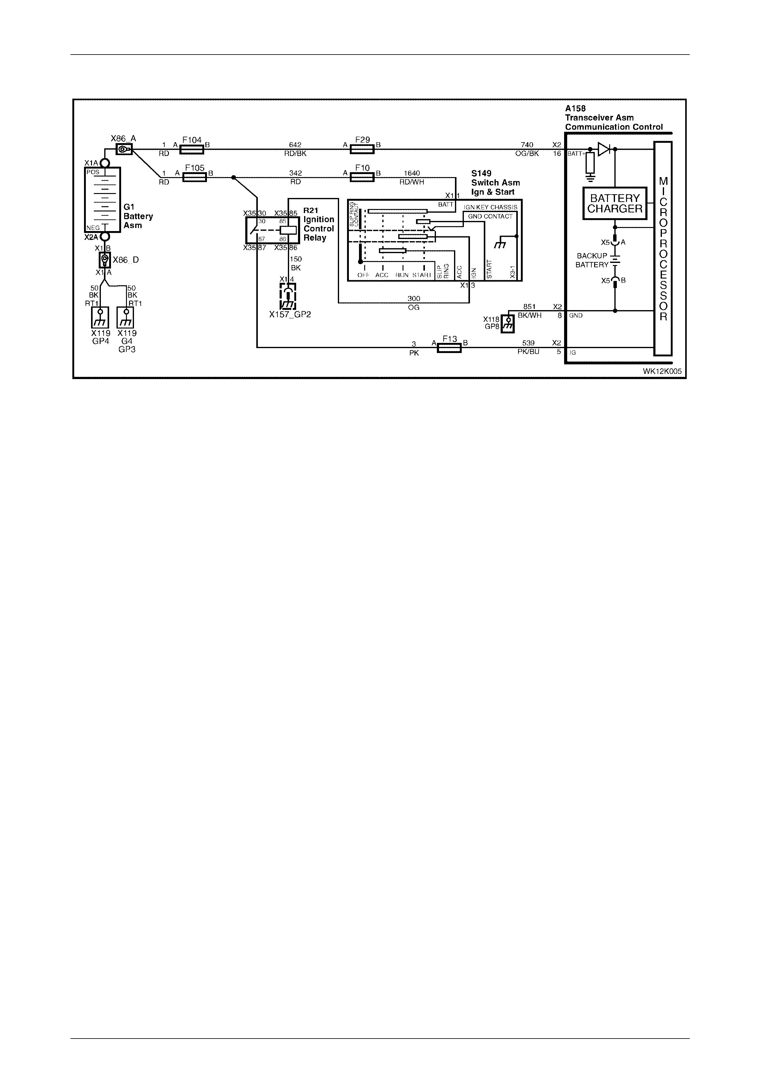
2.3 Battery Voltage
Battery voltage is applied to the telematics module X158 – 2 pin 16 at all times via circuit 740, fuse F29 and fusible link
F104 (refer to Figure 12K – 3). If the battery voltage falls below a preset voltage for longer than 30 minutes, the
telematics module transmits a Low Battery Alert to the Holden Assist Centre. For information on low battery voltage
alert, refer to Section 12K, 2.2 Alerts in the MY 2003 VY and V2 Series Service Inform ation. If the battery is removed
the telematics module transmits a Battery Removal Alert to the Holden Assist Centre. For information on battery
removal, refer to Section 12K, 2.2 Alerts in the MY 2003 VY and V2 Series Service Information.
Figure 12K – 3
Telematics Page 12K–8
Page 12K–8
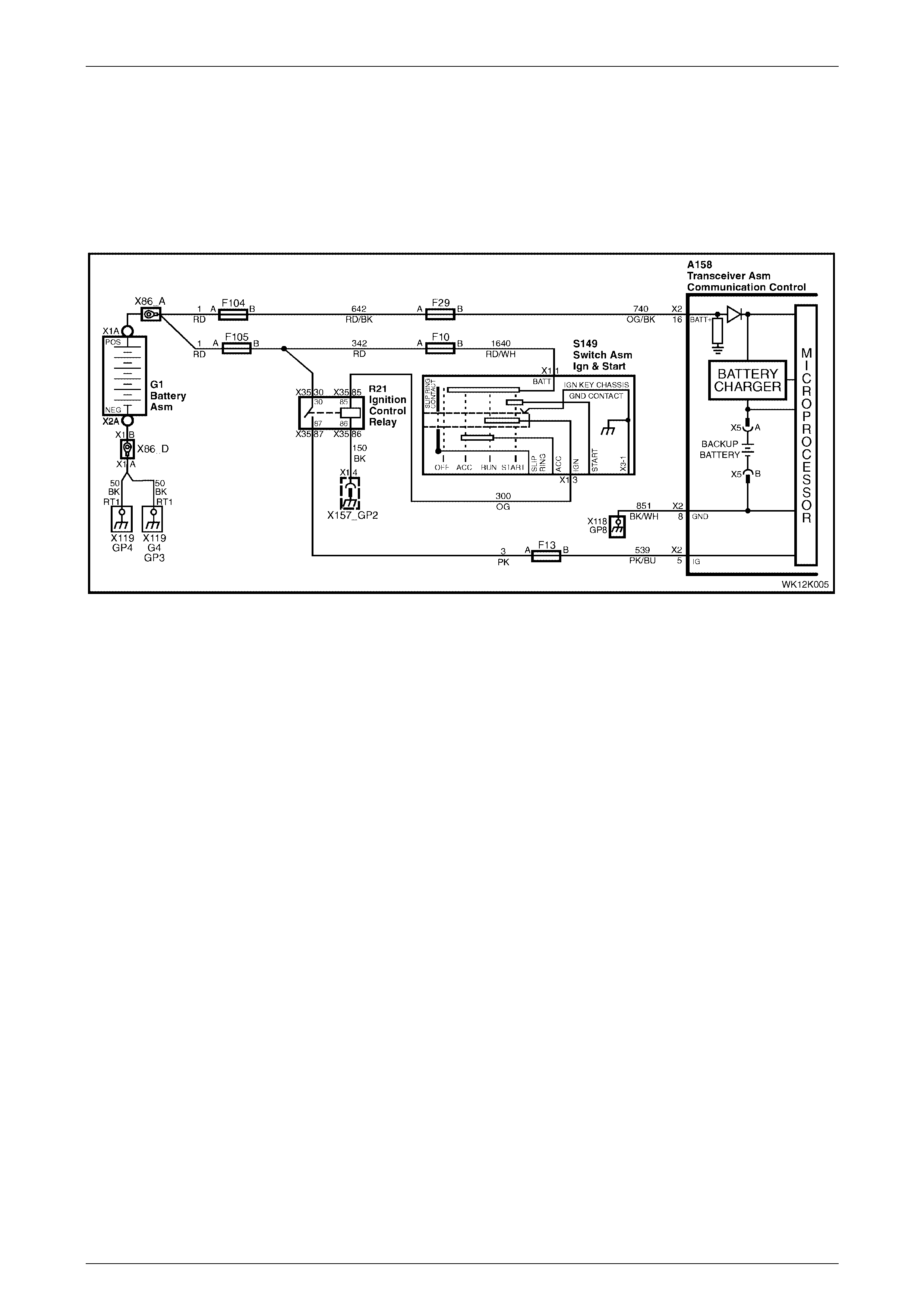
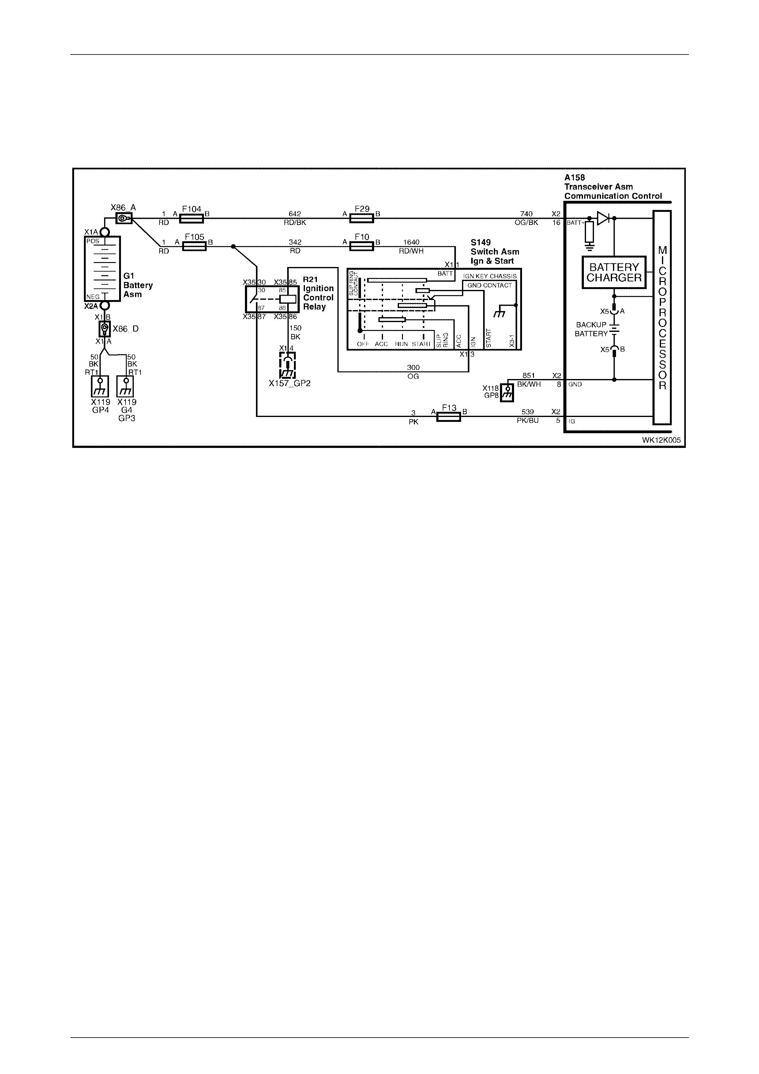
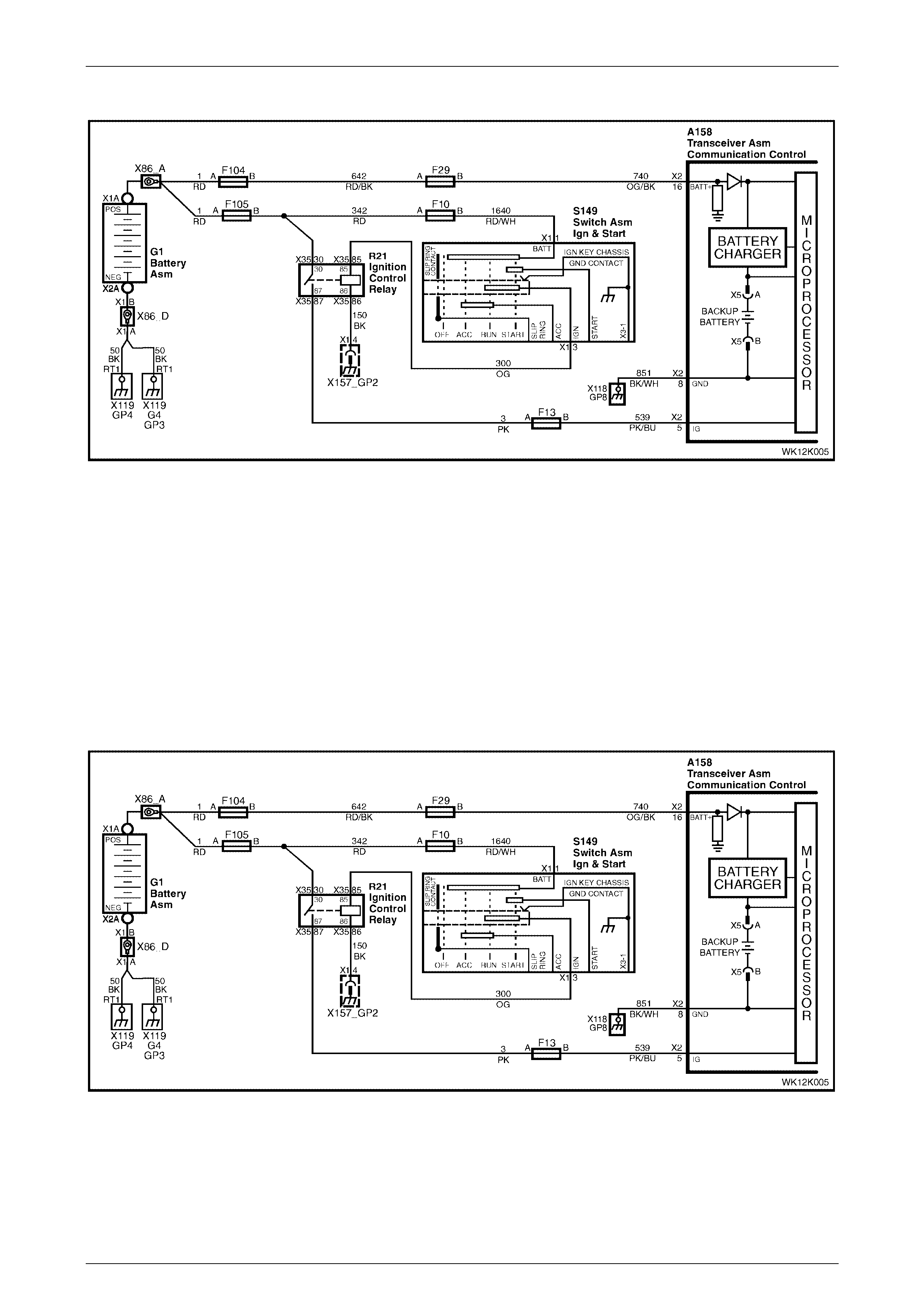
2.4 Backup Battery Charger
The telematics module constantly monitors vehicle battery voltage and backup battery voltage. The charging ci rcuit
constantly monitors the backup battery voltage to determine if the backup battery needs to be charged (at a maximum of
up to 300 mA).
Figure 12K – 4

Telematics Page 12K–9
Page 12K–9
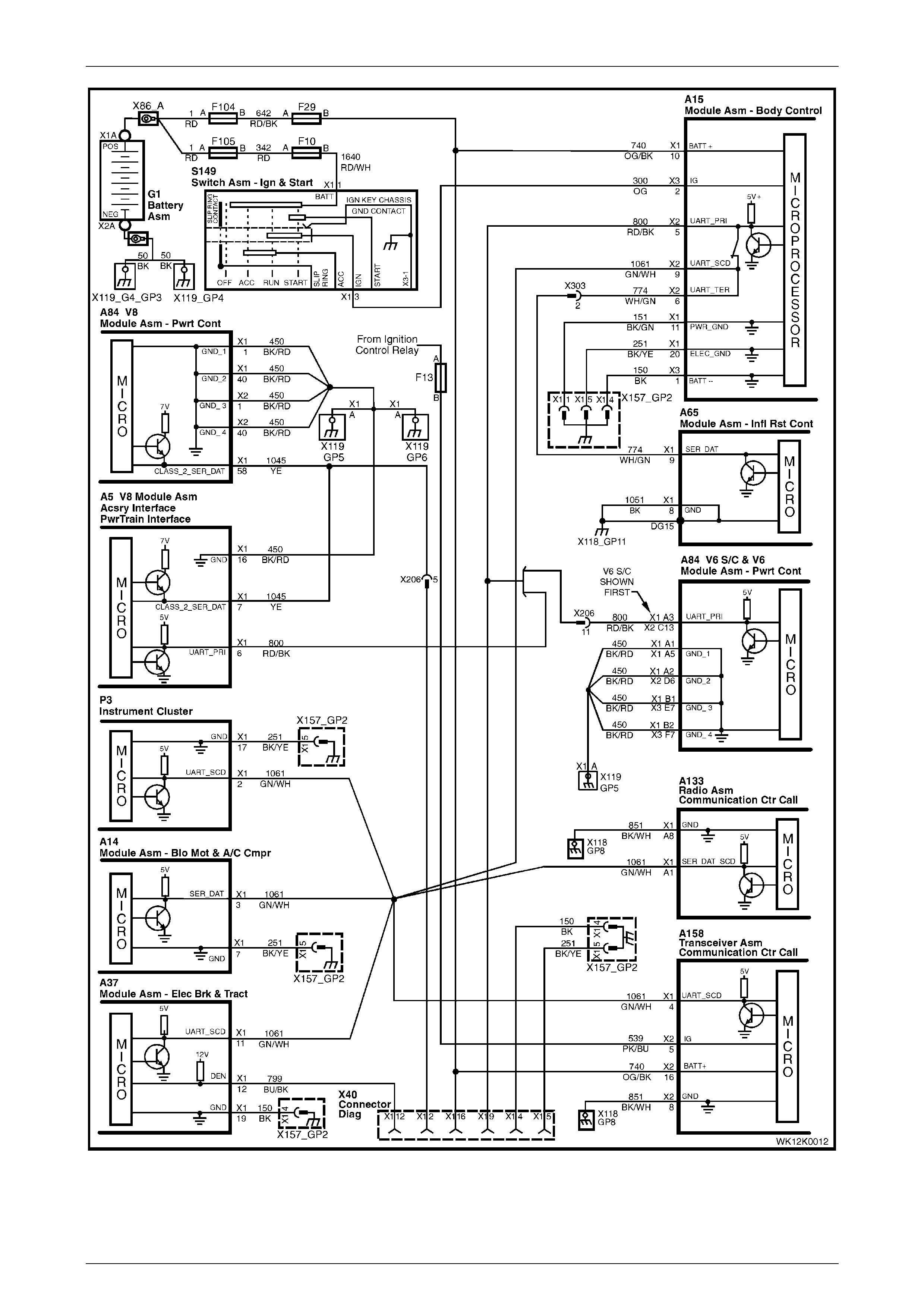
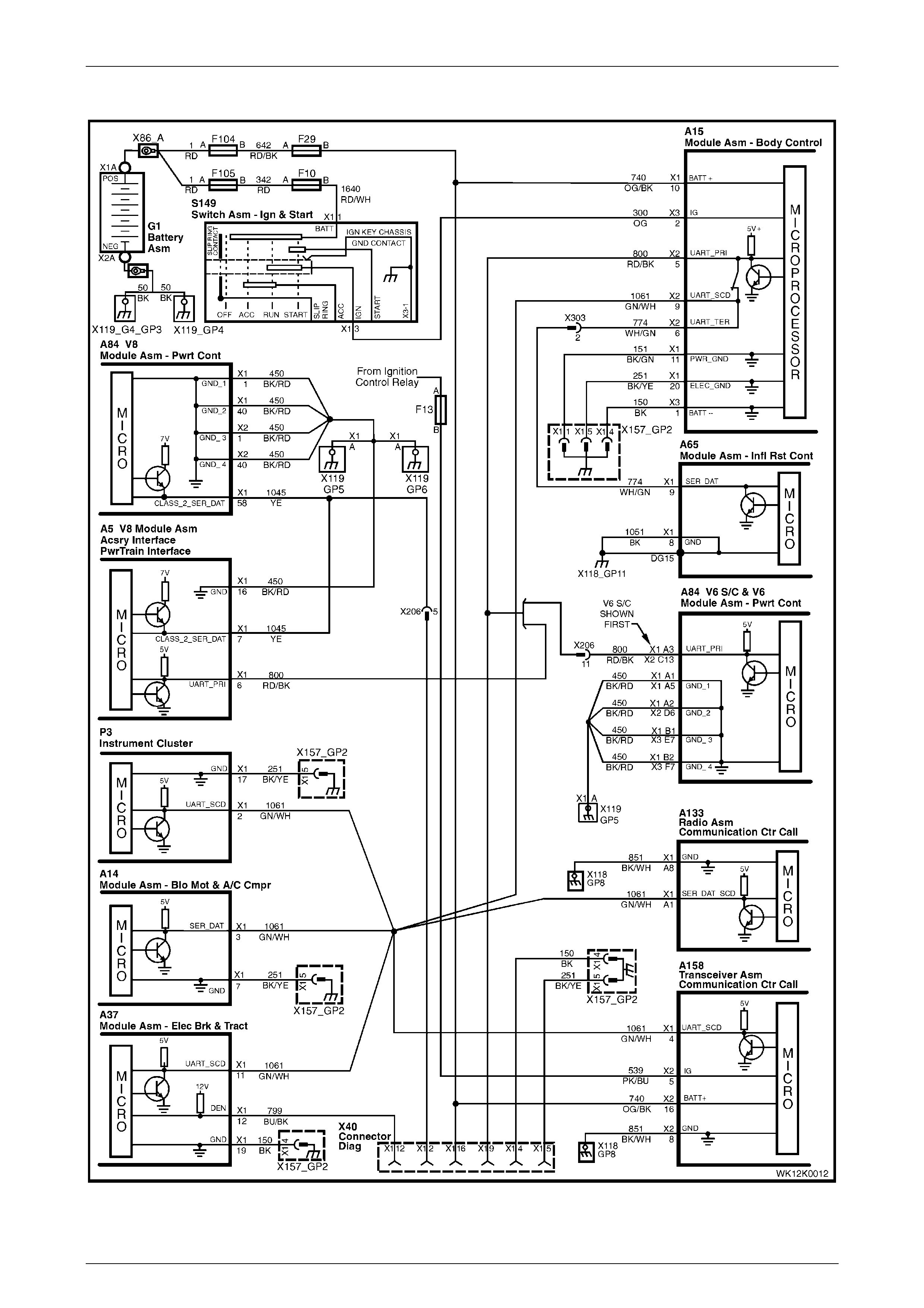
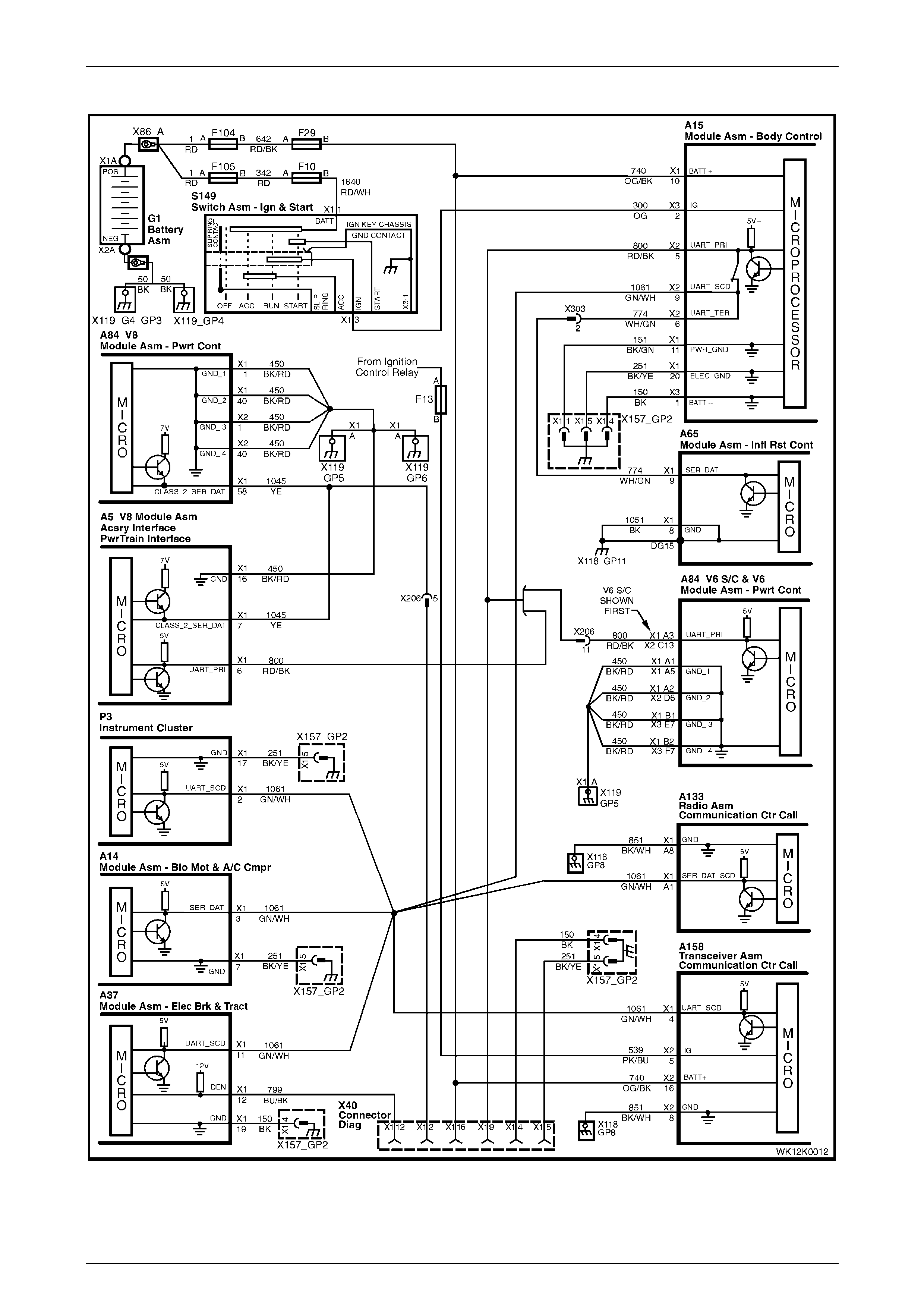
2.5 Serial Data
The telematics module monitors auxiliary serial data circuit 1061 normal mode message for the following data (refer to
Figure 12K – 5):
• Airbag Deployed This Ignition Cycle from the SRS SDM, and
• Vehicle Speed from the PCM.
For information on the serial data bus and normal mode message, refer to Section 12J, 1.2 Serial Data Communication
(Bus Master) in the MY 2003 VY and V2 Series Service Information.
If the telematics module receives a 'Remote Unlock' message from the Holden Assist Centre, the telematics module
requests the BCM (via the serial data circuit) to unlock the doors. For information on the BC M door lock operation, refer
to Section 12J, 1.5 Central Door Locking in the MY 2003 VY and V2 Series Service Information.
If the telematics module receives an 'Immobilise' message from the National Emergency Response Centre (NERCTM),
the telematics module:
• turns off the fuel pump relay (refer to Section 12K, 2.15 Fuel Pump Relay Drive Circ uit in the MY 2003 VY and
V2 Series Service Information) cutting off the supply of fuel to the engine, and
• requests the BCM (via the serial data circuit) to flash the indicators.
For information on BCM indicator operation, refer to Section 12J, 1.7 Theft Deterrent System in the MY 2003 VY and
V2 Series Service Information.
Telematics Page 12K–10
Page 12K–10
Figure 12K – 5
Telematics Page 12K–11
Page 12K–11
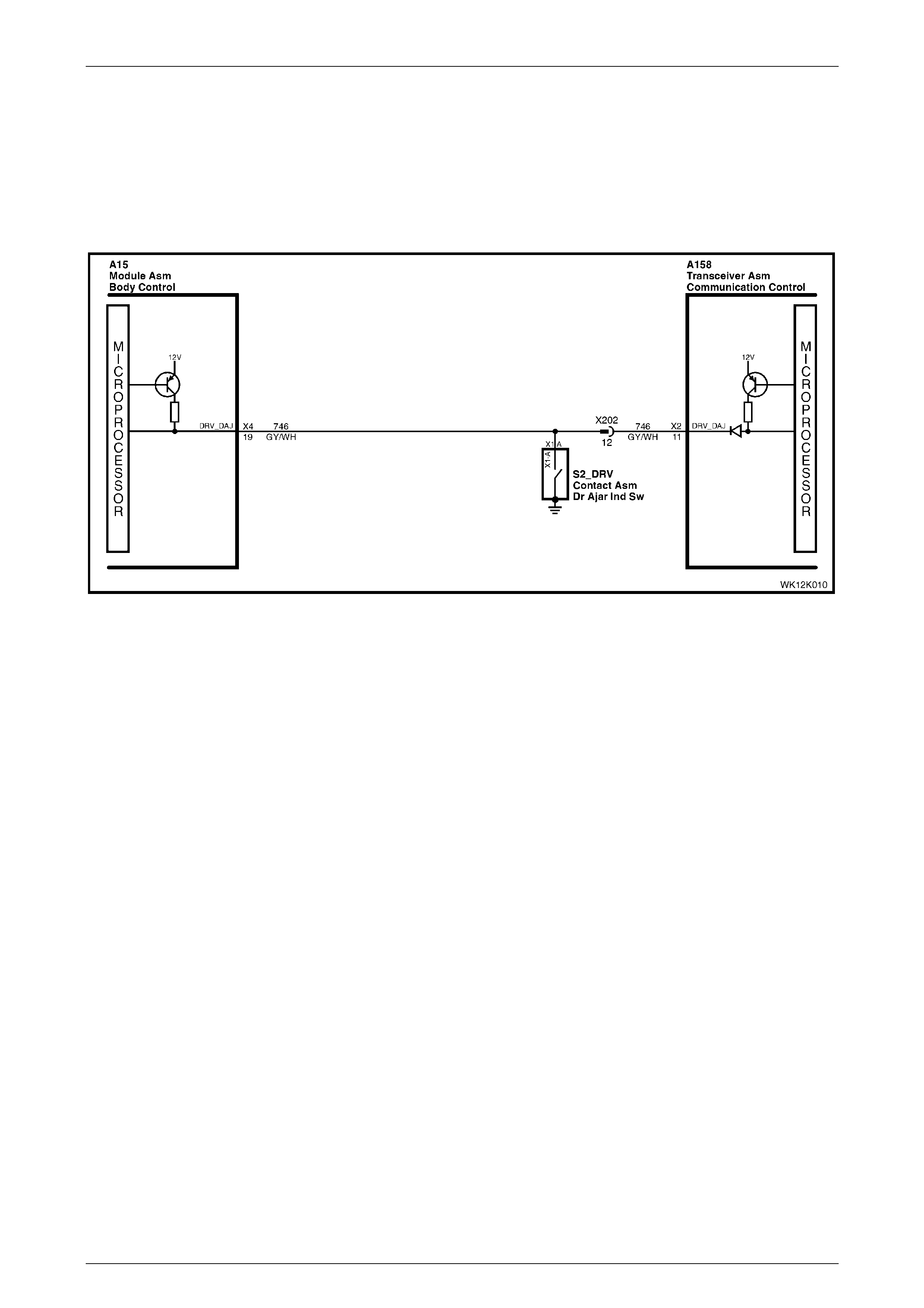
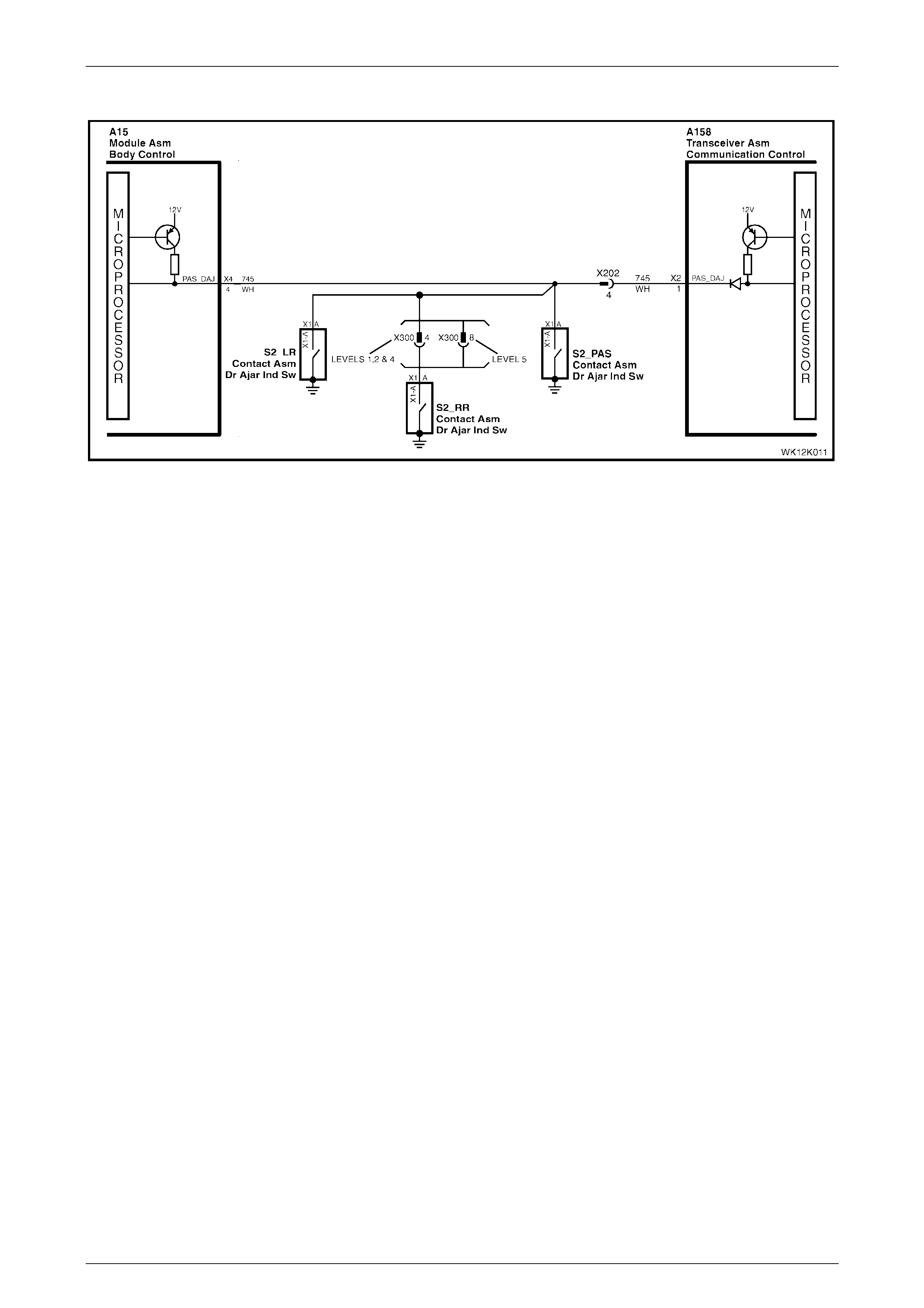
2.6 Driver's Door Ajar Switch
The telematics module uses the driver’s door ajar input signal to determine if the driver's front door is opened or closed.
When the driver’s door is opened, the driver’s door ajar switch grounds A158 – X2 pin 11 of the telematics module via
circuit 746. This causes the voltage at terminal A158 – X2 pin 11 to drop to less than 0.2 volts (indicating that the driver's
door is open). This low voltage at A158 – X2 pin 11 is detected by the telematics module as the driver's door open input
signal. The telematics module uses this input to determine the system operating mode, refer to Section 12K,
2.1 Operating Modes in the MY 2003 VY and V2 Series Service Information.
Figure 12K – 6
Telematics Page 12K–12
Page 12K–12
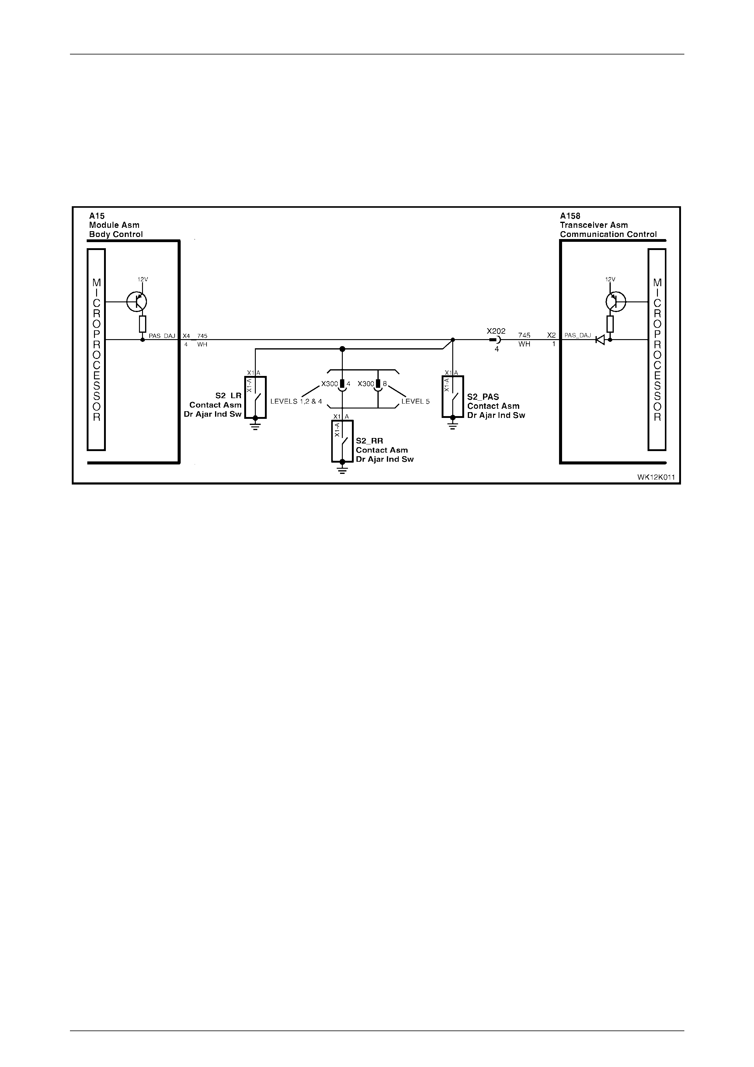
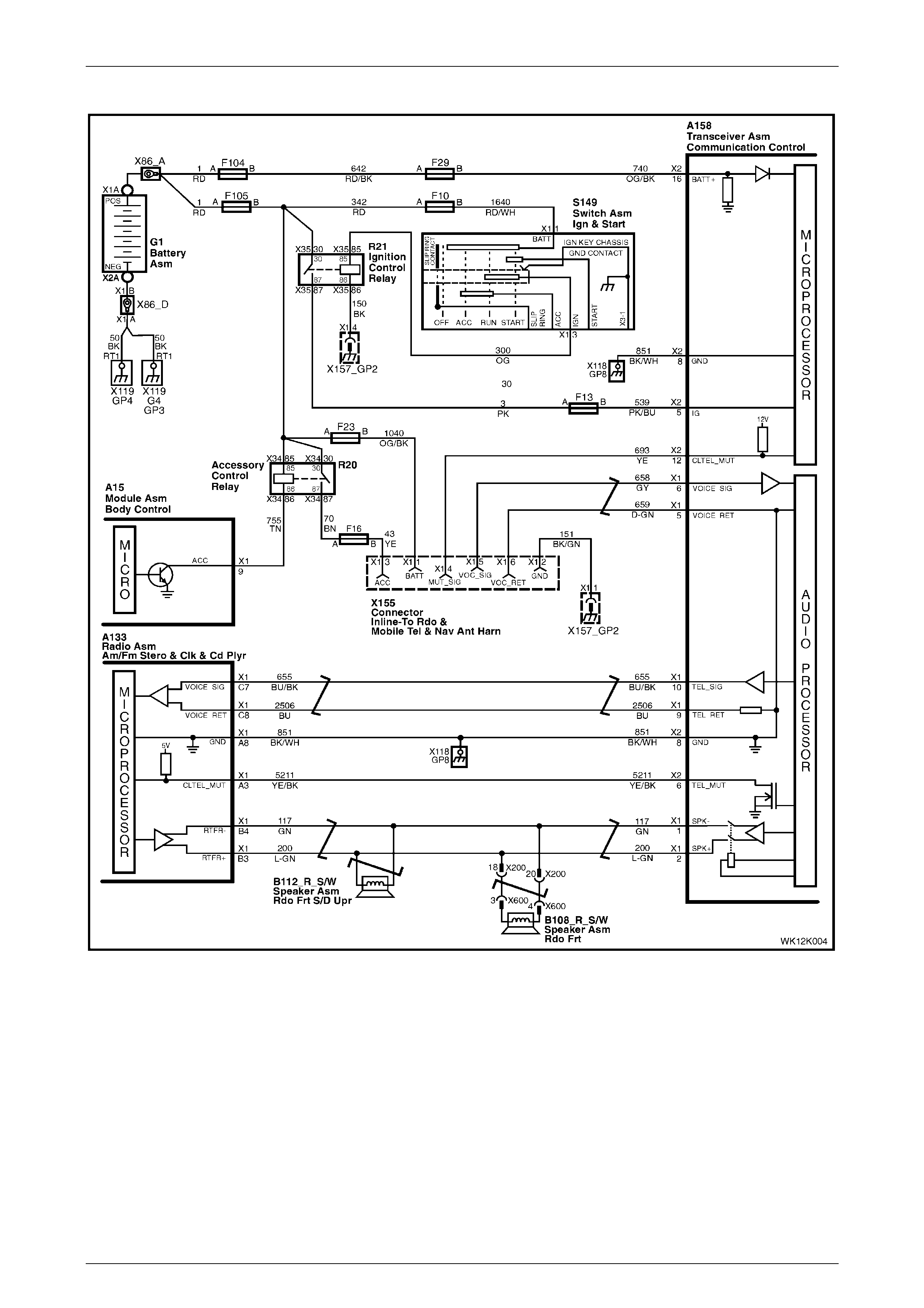
2.7 Passenger Door Ajar Switches
The telematics module uses the passenger door ajar input signal to determine if any of the passenger doors are opened.
If any passenger doors are open, A158 – X2 pin 1 of the telematics module is grounded via circuit 745. This causes the
voltage at A158 – X2 pin 1 to drop to less than 0.2 volts (indicating that one or more passenger doors are open). The
telematics module determines this low voltage at A158 – X2 pin 1 as the passenger door open input signal. The
telematics module uses this input to determine the system operating mode, refer to Section 12K, 2.1 Operating Modes in
the MY 2003 VY and V2 Series Service Information.
Figure 12K – 7

Telematics Page 12K–13
Page 12K–13
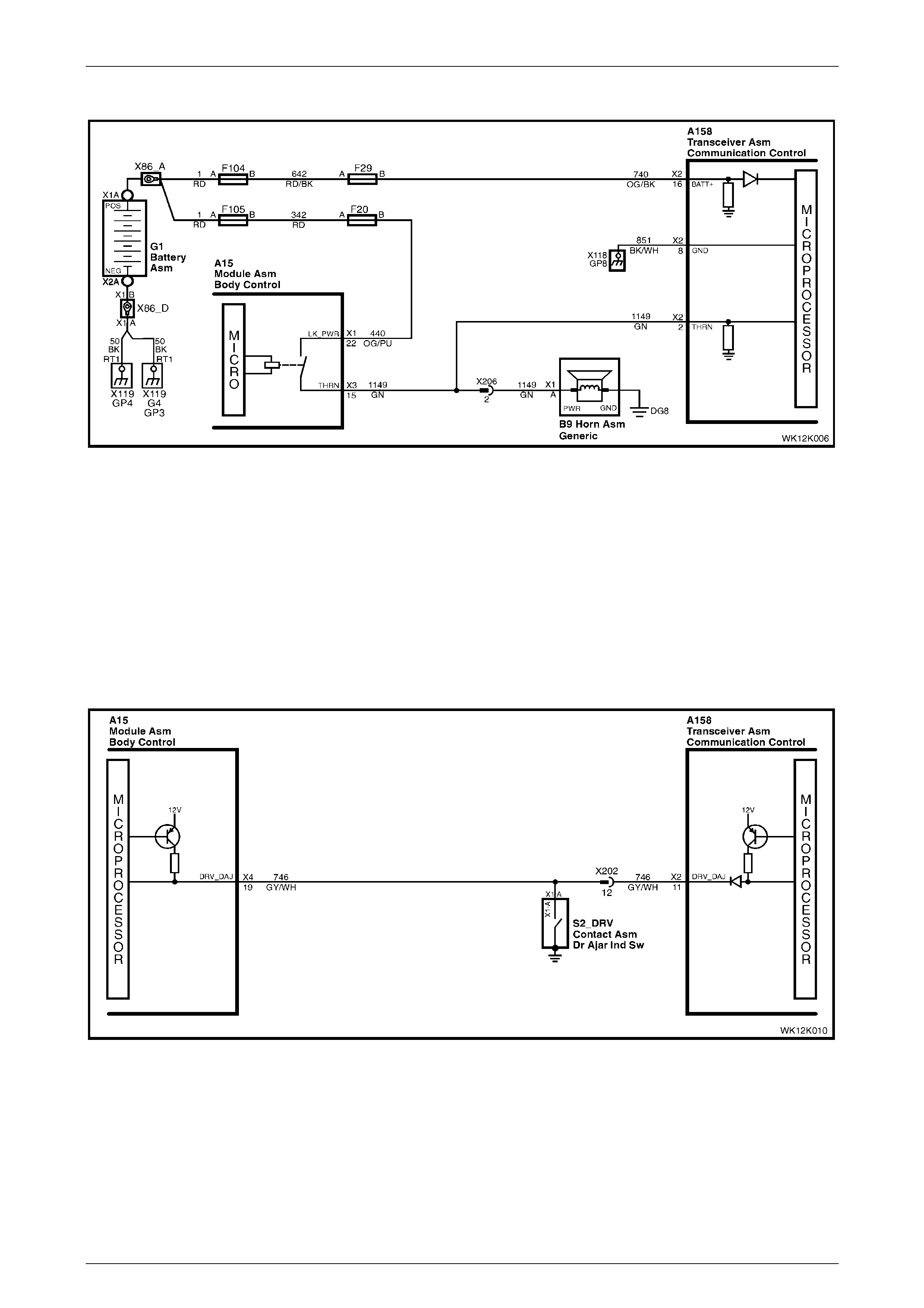
2.8 Alarm Input (Theft Deterrent Horn)
The telematics module monitors the theft deterrent horn circuit to determine if the alarm has been triggered. If the alarm
has been triggered, the body control module (BCM) pulses the vehicle horns at 1 Hz. The BCM supplies 12 volts via
circuit 1149 to pulse the theft deterrent horn. W hen the theft deterrent horn circuit is activated, the voltage at A158 – X2
pin 2 of the telematics module increases. The telematics module determines this high voltage at A158 – X2 pin 2 as the
theft deterrent system having been triggered. If the vehicle theft deterrent system is triggered for longer than
20 seconds, the telematics module transmits an 'Unauthorised Entry Alert' message to the Holden Assist Centre. For
further information regarding the unauthorised entry alert, refer to the Holden Assist Handbook Supplement.
Figure 12K – 8
Telematics Page 12K–14
Page 12K–14
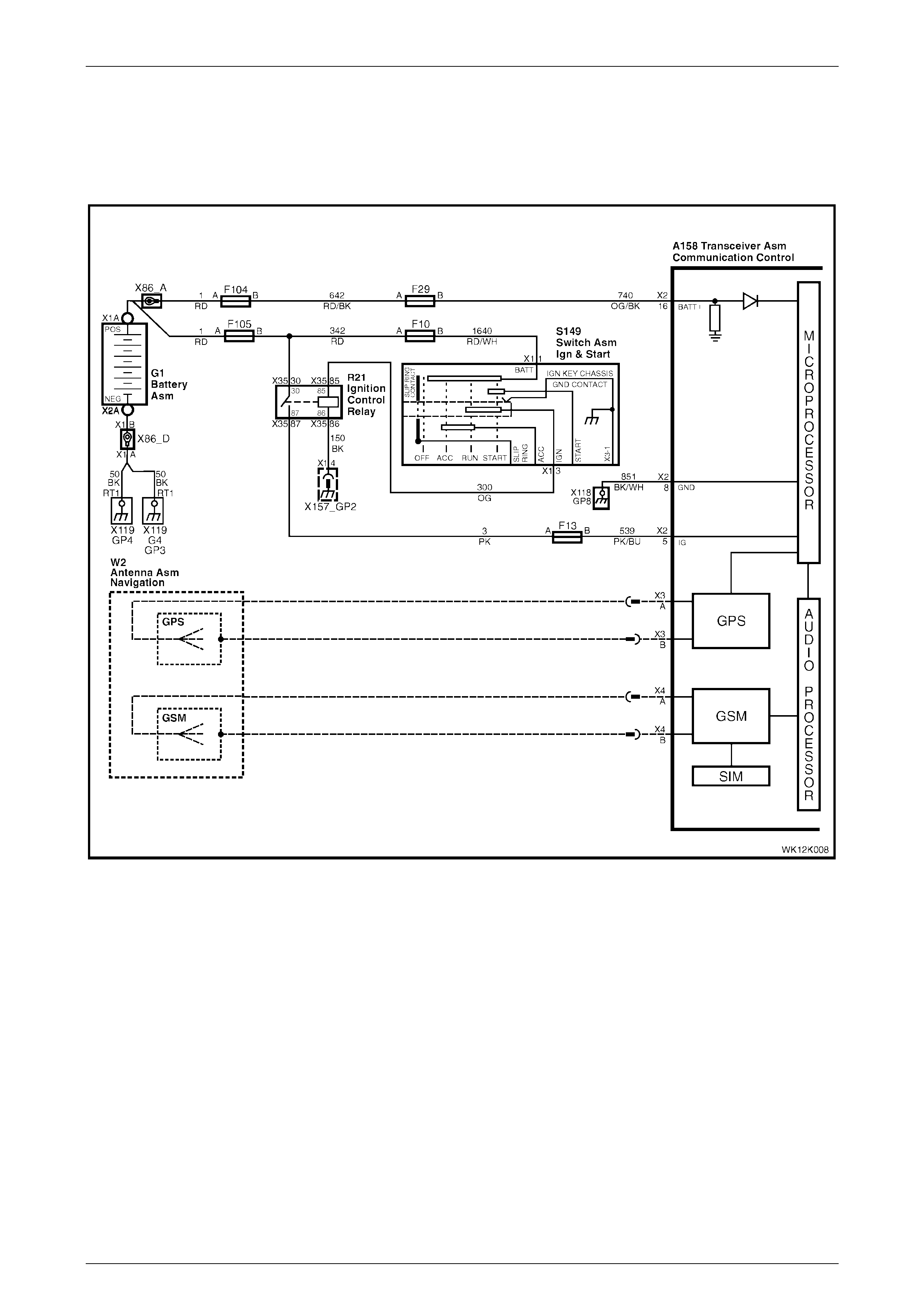
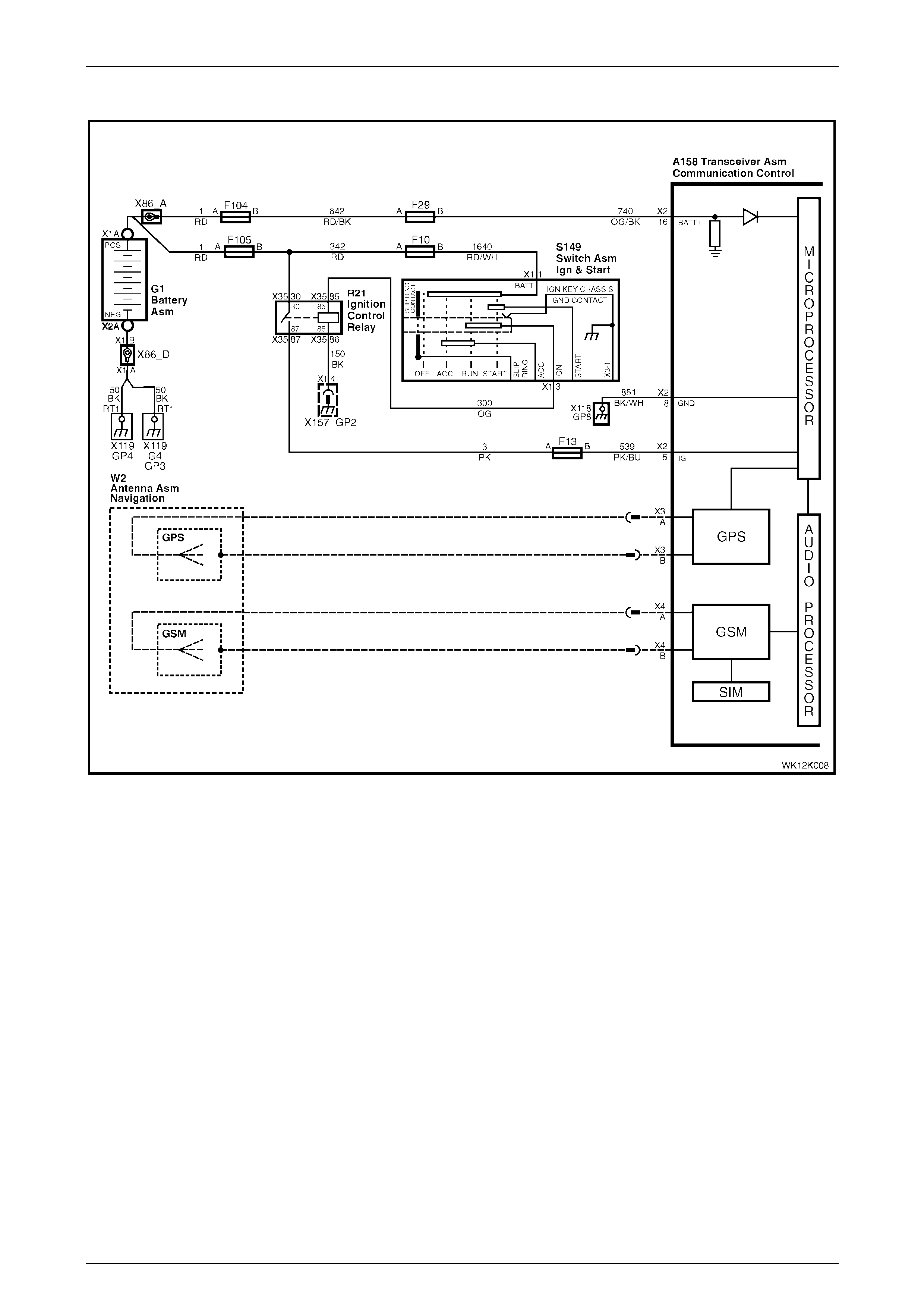
2.9 Telematics Antenna
With the exception of the following wiring diagram, MY 2004 WK Series telematics antenna information carries over from
MY 2003 VY and V2 Series vehicles. For all other telematics antenna information, refer to Section 12K, 2.14 Telematics
Antenna in the MY 2003 VY and V2 Series Service Information.
Figure 12K – 9
Telematics Page 12K–15
Page 12K–15
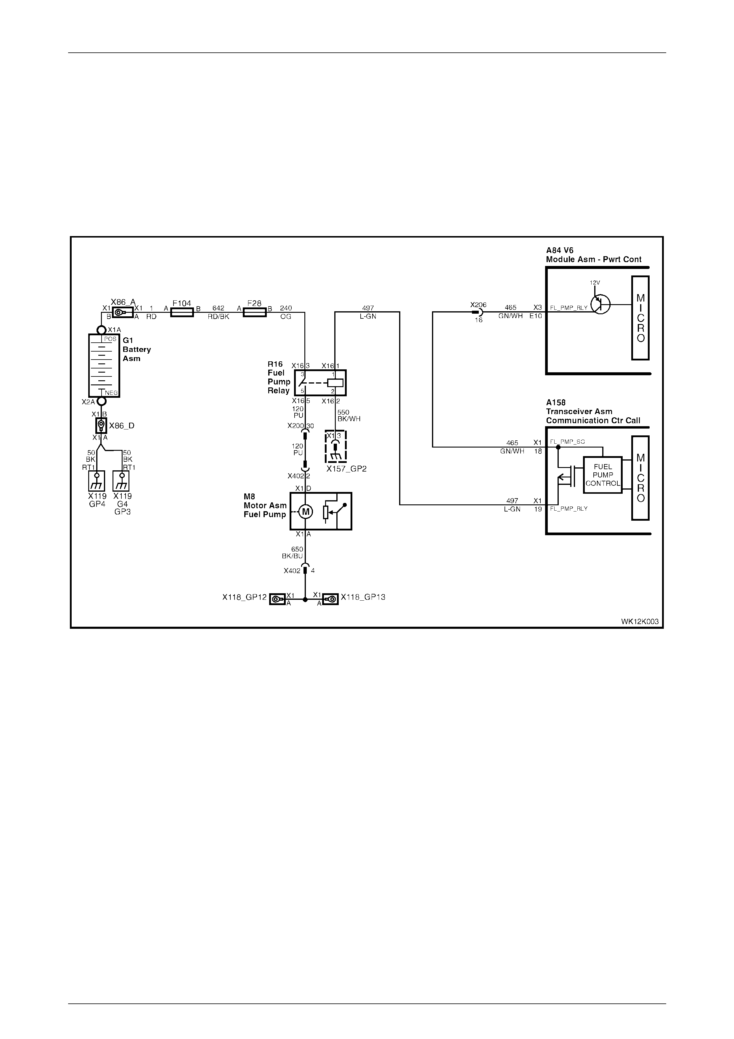
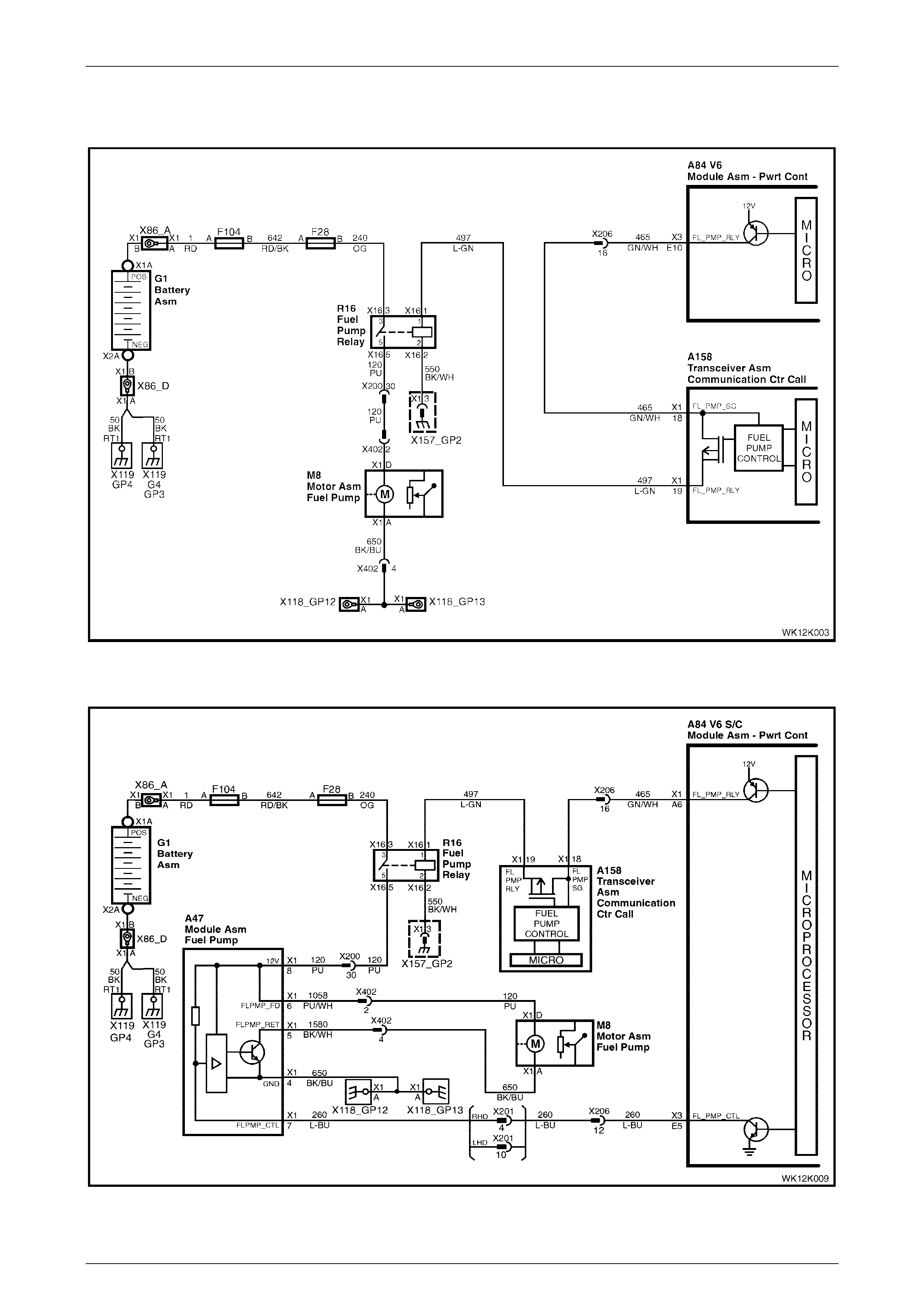
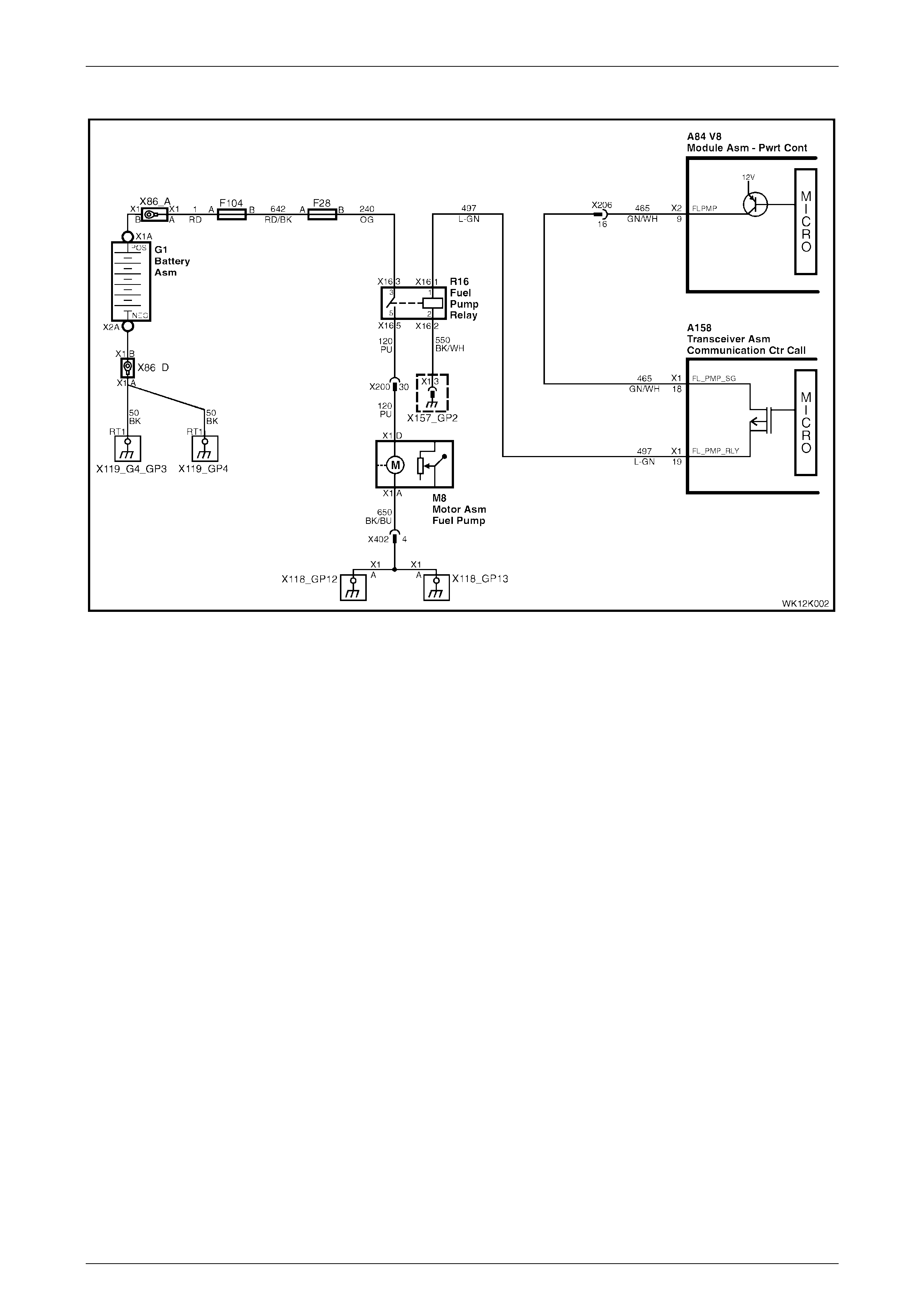
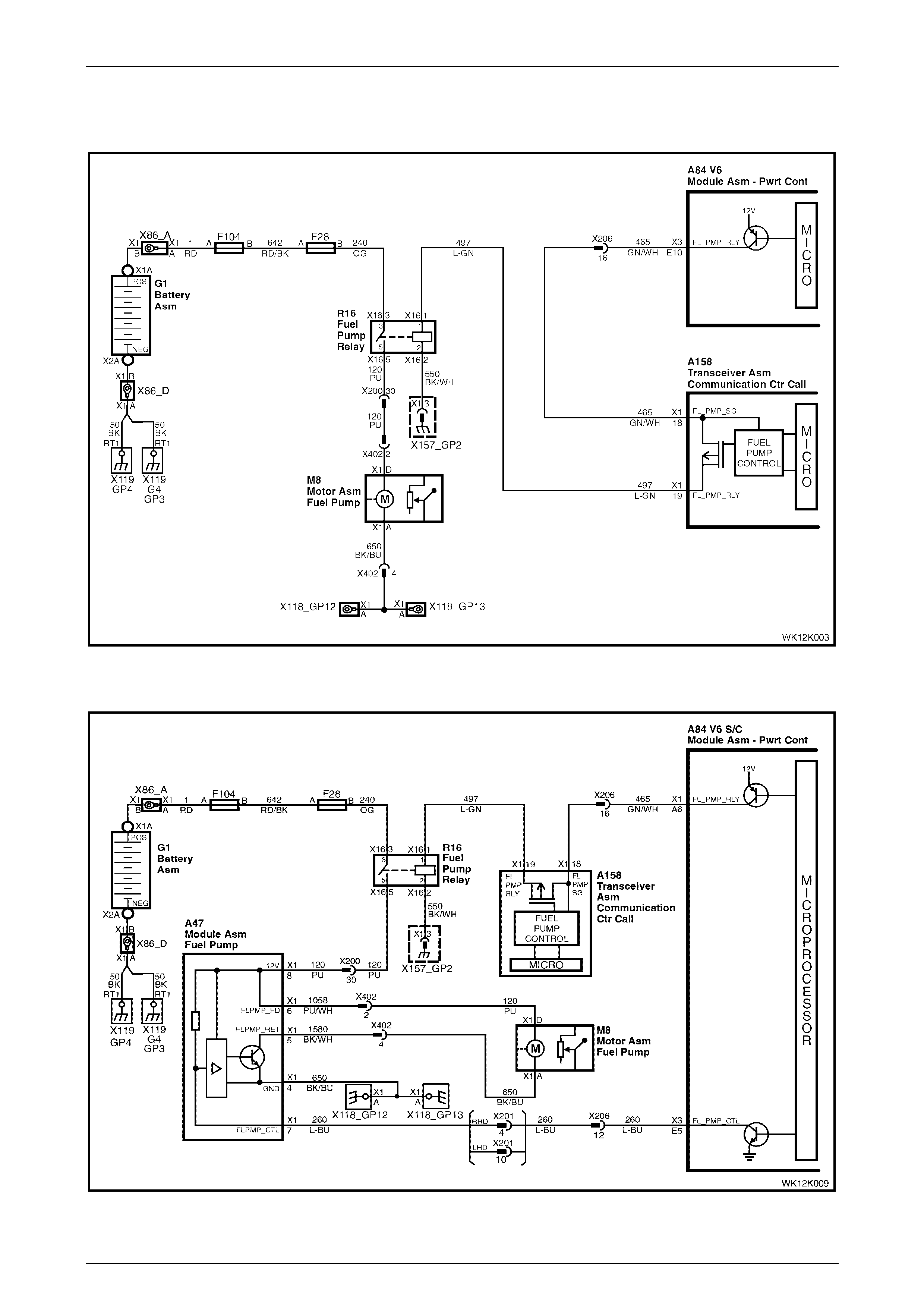
2.10 Fuel Pump Relay Dri ve Circuit
The PCM energises the fuel pump relay drive circuit via circuit 465, and the telematics module A158 – X1 pin 18
circuit 497 and A158 – X1 pin 19 circuit 465. The fuel pump relay drive circuit is grounded through circuit 550 at ground
location X157_GP2. The telematics module immobilises the vehicle by opening the fuel pump relay drive circuit, causing
the fuel pump to stop operating. This function can be activated only by the NERC™ under instruction from the police.
For information on engine immobilisation, refer to Section 12K, 2.3 Holden Assist Remote Requests in the MY 2003 VY
and V2 Series Service Information.
V6 Engine
Figure 12K – 10

Telematics Page 12K–16
Page 12K–16
V6 (Supercharged) Engine
Figure 12K – 11
GEN III V8 Engine
Figure 12K – 12

Telematics Page 12K–17
Page 12K–17
3 Service Operations
MY 2004 WK Series Telematics information carries over from MY 2003 VY and V2 Series vehicl es.
For all Telematics service operations information, refer to Section 12K Telematics, 3 Service Operations in the MY 2003
VY and V2 Series Service Information.
NOTE
Refer to the relevant MY 2004 WK Series
Section for all external references contained
in the MY 2003 VY and V2 Series,
Section 12K Telematics. This is to verify that
there are no differences in the MY 2004
WK Series Service information that will affect the
service procedures referenced from MY 2003 VY
and V2 Series Service information.

Telematics Page 12K–18
Page 12K–18
4 TECH 2 Diagnosis for Telematics
MY 2004 WK Series Telematics information carries over from MY 2003 VY and V2 Series vehicl es.
For all Telematics TECH 2 diagnosis information, refer to Section 12K Telematics, 4 TECH 2 Diagnosis for Telematics in
the MY 2003 VY and V2 Series Service Information.
NOTE
Refer to the relevant MY 2004 WK Series
Section for all external references contained in
the MY 2003 VY and V2 Series,
Section 12K Telematics. This is to verify that
there are no differences in the MY 2004
WK Series Service information that will affect the
service procedures referenced from MY 2003 VY
and V2 Series Service information.

Telematics Page 12K–19
Page 12K–19
5 Diagnosis
Except for the following headings and accompanying text, illustrations and/or tables, MY 2004 WK Seri es Telematics
diagnosis information carries over from MY 2003 VY and V2 Series vehicles:
• Telematics Module Terminal Descriptions;
• Diagnostic Charts:
• On-board Diagnostic System Check,
• DTC 1 — No Serial Data From BCM,
• DTC 2 — No Serial Data From Instrument,
• DTC 3 — No Serial Data From Sensing Diagnostic Module,
• DTC 4 — No Serial Data From Audio System,
• DTC 5 — No Serial Data,
• DTC 9 — Vehicle Battery Voltage Too High,
• DTC 10 — Vehicl e Battery Voltage Too Low,
• DTC 13 — Backup Battery Timer Expired,
• DTC 14 — Backup Battery Voltage Too High,
• DTC 15 — Backup Battery Voltage Too Low,
• DTC 16 — Backup Battery Not Detected,
• DTC 17 — Microphone Not Detected,
• DTC 18 — Microphone Circuit Voltage Too Low,
• DTC 19 — Microphone Circuit Voltage Too High,
• DTC 21 — Speaker Circuit Voltage Too Low,
• DTC 22 — Speaker Circuit Voltage Too High,
• DTC 30 — Keypad Circuit Voltage Too High,
• DTC 42 — Fuel Pump Circuit Voltage Too Low,
• DTC 43 — Fuel Pump Circuit Voltage Too High,
• DTC 45 — End Call / Information Button Stuck,
• DTC 46 — Holden Assist Button Stuck, and
• DTC 47 — Emergency Button Stuck; and
• Symptoms Charts:
• No Serial Data,
• Status Indicator LEDs Do Not Illuminate,
• Vehicle Battery Voltage,
• Backup Battery,
• No GPS Signal,
• No GSM Signal,
• Emergency Button,
• Holden Assist Button,
• End Call / Information Button,
Techline

Telematics Page 12K–20
Page 12K–20
• Theft Deterrent Horn,
• Driver's Door Ajar Switch,
• Passenger Door Ajar Switches,
• Microphone,
• Fuel Pump Relay Drive,
• Audio Mute,
• Audio System Interface,
• Unable to Make or Receive a Call, and
• Holden Assist Telematics System Test.
For other diagnosis information not contained within this Section, refer to Section 12K Telematics in the MY 2003 VY and
V2 Series Service information.
NOTE
Refer to the relevant MY 2004 WK Series
Section for all external references contained
in the MY 2003 VY and V2 Series,
Section 12K Telematics. This is to verify that
there are no differences in the MY 2004
WK Series Service information that will affect the
service procedures referenced from MY 2003 VY
and V2 Series Service information.
Telematics Page 12K–21
Page 12K–21
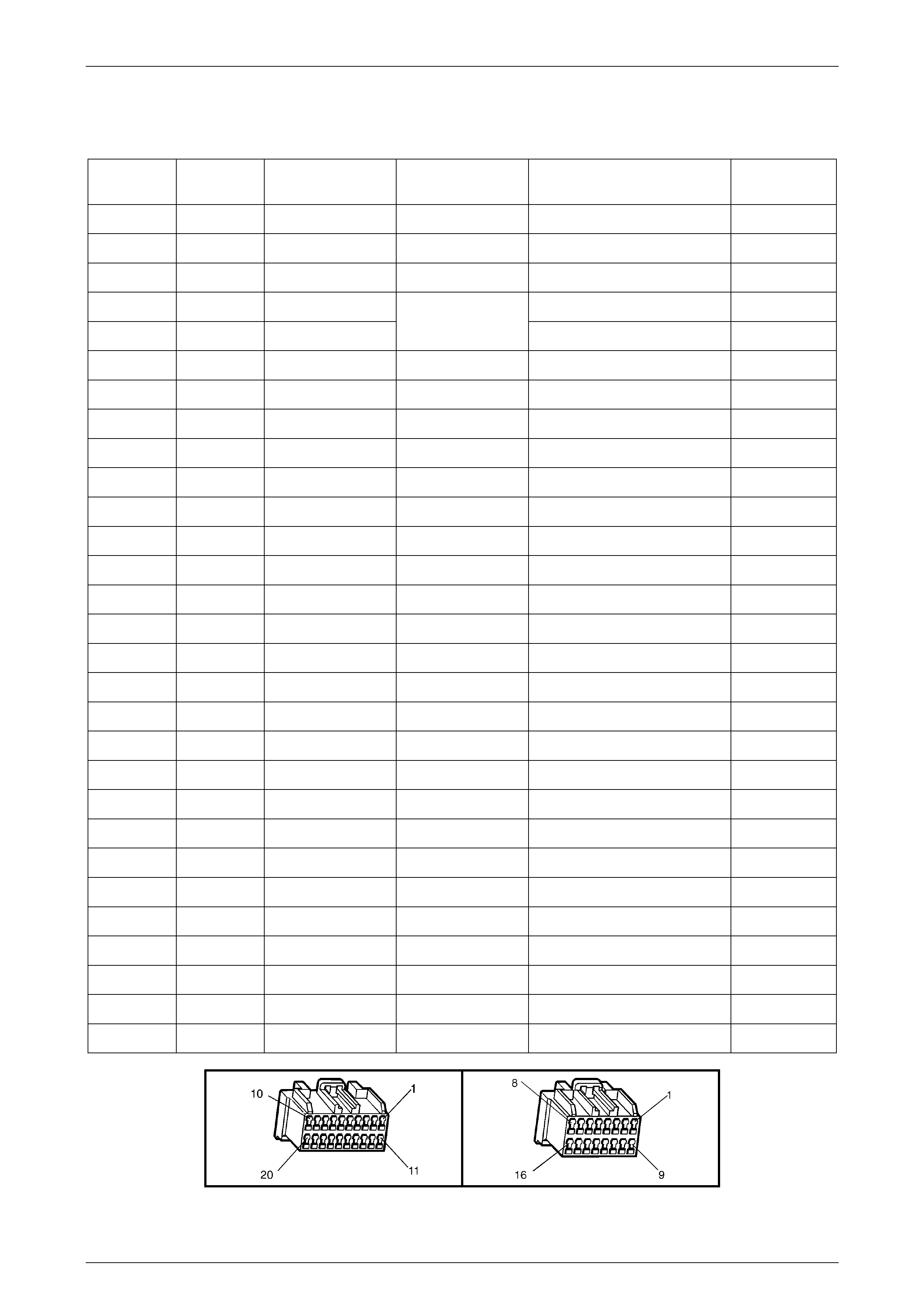
5.1 Telematics Module Terminal
Descriptions
Pin No.
A158 Circuit
No. Circuit
Colour IVED
Abbreviation Description Circuit
Type
X1–1 117 Green SPK_– Speaker Negative Output
X1–2 200 Light Green SPK_+ Speaker Positive Output
X1–4 1061 Green / White UART_SCD Serial Data (Secondary) I/O
X1–5 659 Dark Green VOICE_RET Phone Signal In Ground Ground
X1–6 658 Grey VOICE_SIG Phone Signal In Input
X1–7 1153 Brown MIC– Microphone Negative Ground
X1–8 1155 Green MIC+ Microphone Positive Input
X1–9 2506 Blue TEL_RET Phone Signal Out Ground Ground
X1–10 655 Blue / Black TEL_SIG Phone Signal Out Output
X1–18 465 Green White FL_PMP_SG Fuel Pump Relay In Input
X1–19 497 Light Green FL_PMP_RLY Fuel Pump Relay Out Output
X2–1 745 White PAS_DAJ Passenger Door Ajar Switches Input
X2–2 1149 Green THRN Theft Deterrent Horn Relay Input
X2–5 539 Pink / Blue IG Ignition Input
X2–6 5211 Yellow / Black TEL_MUT Radio Mute Output
X2–7 2517 Brown / White RD_LED Red LED Output
X2–8 851 Black / White GND Ground Ground
X2–9 2514 Green / White KEY_DAT Key Pad Signal Input
X2–11 746 Grey / White DRV_DAJ Driver’s Door Ajar Switch Input
X2–12 693 Yellow CLTEL_MUT Phone Mute In Input
X2–14 2516 Yellow / Black GN_LED Green LED Output
X2–15 2515 Light Green / Black KEY_PWR Key Pad Supply Voltage Output
X2–16 740 Orange / Black BATT+ Battery Posi tive B+
X3–A N/A N/A N/A GPS Antenna Signal Input
X3–B N/A N/A N/A GPS Antenna Ground Ground
X4–A N/A N/A N/A GSM Antenna Signal Input
X4–B N/A N/A N/A GSM Antenna Ground Ground
X5–A N/A N/A N/A Back Up Battery Positive 7.2 Volts
X5–B N/A N/A N/A Back Up Battery Negative Ground
A158 X1 A158 X2
Telematics Page 12K–22
Page 12K–22
5.2 Diagnostic Charts
With the exception of the following headings, and accompanying wiring diagrams and text, MY 2004 WK Series
diagnostic charts information carries over from MY 2003 VY and V2 Series vehicles. For all other diagnostic charts
information, refer to Section 12K, 5.8 Diagnostic Charts in the MY 2003 VY and V2 Series Service Information.
On-board Diagnostic System Check
Figure 12K – 13
For information on the circuit description, and a test description and accompanying table for the on-board diagnostic
system check test, refer to Section 12K, 5.8 Diagnostic Charts (On-board Diagnostic System Check) in the MY 2003 VY
and V2 Series Service Information.

Telematics Page 12K–23
Page 12K–23
DTC 1 — No Serial Data From BCM
Figure 12K – 14

Telematics Page 12K–24
Page 12K–24
For information on:
• the circuit description,
• conditions for setti ng t he DTC ,
• action taken when the DTC sets, and
• a test description and accompanying table
Refer to, Section 12K, 5.8 Diagnostic Charts (DTC 1 — No Serial Data From BCM) in the MY 2003 VY and V2 Series
Service Information.
Telematics Page 12K–25
Page 12K–25
DTC 2 — No Serial Data From Instrument
Figure 12K – 15

Telematics Page 12K–26
Page 12K–26
For information on:
• the circuit description,
• conditions for setti ng t he DTC ,
• action taken when the DTC sets, and
• a test description and accompanying table
Refer to Section 12K, 5.8 Diagnostic Charts (DTC 2 — No Serial Data From Instrument) in the MY 2003 VY and
V2 Series Service Information.

Telematics Page 12K–27
Page 12K–27
DTC 3 — No Serial Data From Sensing Diagnostic Module
Figure 12K – 16

Telematics Page 12K–28
Page 12K–28
For information on:
• the circuit description,
• conditions for setti ng t he DTC ,
• action taken when the DTC sets, and
• a test description and accompanying table
Refer to Section 12K, 5.8 Diagnostic Charts (DTC 3 — No Serial Data From SDM (Sensing Diagnostic Module)) in the
MY 2003 VY and V2 Series Service Information.

Telematics Page 12K–29
Page 12K–29
DTC 4 — No Serial Data From Audio S ystem
Figure 12K – 17

Telematics Page 12K–30
Page 12K–30
For information on:
• the circuit description,
• conditions for setti ng t he DTC ,
• action taken when the DTC sets, and
• a test description and accompanying table
Refer to Section 12K, 5.8 Diagnostic Charts (DTC 4 — No Serial Data From Audio System) in the MY 2003 VY and
V2 Series Service Information.

Telematics Page 12K–31
Page 12K–31
DTC 5 — No Serial Data
Figure 12K – 18

Telematics Page 12K–32
Page 12K–32
For information on:
• the circuit description,
• conditions for setti ng t he DTC ,
• action taken when the DTC sets, and
• a test description and accompanying table
Refer to Section 12K, 5.8 Diagnostic Charts (DTC 3 — No Serial Data) in the MY 2003 VY and V2 Series Service
Information.
Telematics Page 12K–33
Page 12K–33
DTC 9 — Vehicle Battery Voltage Too High
Figure 12K – 19
For information on:
• the circuit description,
• conditions for setti ng t he DTC ,
• action taken when the DTC sets, and
• a test description and accompanying table
Refer to Section 12K, 5.8 Diagnostic Charts (DTC 9 — Vehicle Battery Voltage Too High) in the MY 2003 VY and
V2 Series Service Information.

Telematics Page 12K–34
Page 12K–34
DTC 10 — Vehicle Battery Voltage Too Low
Figure 12K – 20
For information on:
• the circuit description,
• conditions for setti ng t he DTC ,
• action taken when the DTC sets, and
• a test description and accompanying table
Refer to Section 12K, 5.8 Diagnostic Charts (DTC 10 — Vehicle Battery Voltage Too Low) in the MY 2003 VY and
V2 Series Service Information.

Telematics Page 12K–35
Page 12K–35
DTC 13 — Backup Battery Timer Expir ed
Figure 12K – 21
For information on:
• the circuit description,
• conditions for setti ng t he DTC ,
• action taken when the DTC sets, and
• a test description and accompanying table
Refer to Section 12K, 5.8 Diagnostic Charts (DTC 13 — Backup Battery Timer Expired) in the MY 2003 VY and
V2 Series Service Information.

Telematics Page 12K–36
Page 12K–36
DTC 14 — Backup Battery Voltage Too High
Figure 12K – 22
For information on:
• the circuit description,
• conditions for setti ng t he DTC ,
• action taken when the DTC sets, and
• a test description and accompanying table
Refer to Section 12K, 5.8 Diagnostic Charts (DTC 14 — Backup Battery Voltage Too High) in the MY 2003 VY and
V2 Series Service Information.

Telematics Page 12K–37
Page 12K–37
DTC 15 — Backup Battery Voltage Too Low
Figure 12K – 23
For information on:
• the circuit description,
• conditions for setti ng t he DTC ,
• action taken when the DTC sets, and
• a test description
Refer to Section 12K, 5.8 Diagnostic Charts (DTC 15 — Backup Battery Voltage Too Low) in the MY 2003 VY and
V2 Series Service Information.

Telematics Page 12K–38
Page 12K–38
DTC 16 — Backup Battery Not Detected
Figure 12K – 24
For information on:
• the circuit description,
• conditions for setti ng t he DTC ,
• action taken when the DTC sets, and
• a test description and accompanying table
Refer to Section 12K, 5.8 Diagnostic Charts (DTC 16 — Backup Battery Not Detected) in the MY 2003 VY and
V2 Series Service Information.

Telematics Page 12K–39
Page 12K–39
DTC 17 — Microphone Not Detected
Figure 12K – 25
For information on:
• the circuit description,
• conditions for setti ng t he DTC ,
• action taken when the DTC sets, and
• a test description and accompanying table
Refer to Section 12K, 5.8 Diagnostic Charts (DTC 17 — Microphone Not Detected) in the MY 2003 VY and V2 Series
Service Information.

Telematics Page 12K–40
Page 12K–40
DTC 18 — Microphone Circuit Voltage Too Low
Figure 12K – 26
For information on:
• the circuit description,
• conditions for setti ng t he DTC ,
• action taken when the DTC sets, and
• a test description and accompanying table
Refer to Section 12K, 5.8 Diagnostic Charts (DTC 18 — Microphone Circuit Voltage Too Low) in the MY 2003 VY and
V2 Series Service Information.

Telematics Page 12K–41
Page 12K–41
DTC 19 — Microphone Circuit Voltage Too High
Figure 12K – 27
For information on:
• the circuit description,
• conditions for setti ng t he DTC ,
• action taken when the DTC sets, and
• a test description and accompanying table
Refer to Section 12K, 5.8 Diagnostic Charts (DTC 19 — Microphone Circuit Voltage Too High) in the MY 2003 VY and
V2 Series Service Information.

Telematics Page 12K–42
Page 12K–42
DTC 21 — Speaker Circuit Voltage Too Low
Figure 12K – 28
For information on:
• the circuit description,
• conditions for setti ng t he DTC ,
• action taken when the DTC sets, and
• a test description and accompanying table
Refer to Section 12K, 5.8 Diagnostic Charts (DTC 21 — Speaker Circuit Voltage Too Low) in the MY 2003 VY and
V2 Series Service Information.

Telematics Page 12K–43
Page 12K–43
DTC 22 — Speaker Circuit Voltage Too High
Figure 12K – 29
For information on:
• the circuit description,
• conditions for setti ng t he DTC ,
• action taken when the DTC sets, and
• a test description and accompanying table
Refer to Section 12K, 5.8 Diagnostic Charts (DTC 22 — Speaker Circuit Voltage Too High) in the MY 2003 VY and
V2 Series Service Information.

Telematics Page 12K–44
Page 12K–44
DTC 30 — Keypad Circuit Voltage Too High
Figure 12K – 30
For information on:
• the circuit description,
• conditions for setti ng t he DTC ,
• action taken when the DTC sets, and
• a test description and accompanying table
Refer to Section 12K, 5.8 Diagnostic Charts (DTC 30 — Keypad Circuit Voltage Too High) in the MY 2003 VY and
V2 Series Service Information.
Telematics Page 12K–45
Page 12K–45
DTC 42 — Fuel Pump Circuit Voltage Too Low
V6 Engine
Figure 12K – 31
V6 Supercharged Engine
Figure 12K – 32
Telematics Page 12K–46
Page 12K–46
GEN III V8 Engine
Figure 12K – 33
For information on:
• the circuit description,
• conditions for setti ng t he DTC ,
• action taken when the DTC sets, and
• a test description and accompanying table
Refer to Section 12K, 5.8 Diagnostic Charts (DTC 42 — Fuel Pump Circuit Voltage Too Low) in the MY 2003 VY and
V2 Series Service Information.
Telematics Page 12K–47
Page 12K–47
DTC 43 — Fuel Pump Circuit Voltage Too High
V6 Engine
Figure 12K – 34
V6 Supercharged Engine
Figure 12K – 35

Telematics Page 12K–48
Page 12K–48
GEN III V8 Engine
Figure 12K – 36
For information on:
• the circuit description,
• conditions for setti ng t he DTC ,
• action taken when the DTC sets, and
• a test description and accompanying table
Refer to Section 12K, 5.8 Diagnostic Charts (DTC 43 — Fuel Pump Circuit Voltage Too High) in the MY 2003 VY and
V2 Series Service Information.

Telematics Page 12K–49
Page 12K–49
DTC 45 — End Call / Information Butt on Stuck
Figure 12K – 37
For information on:
• the circuit description,
• conditions for setti ng t he DTC ,
• action taken when the DTC sets, and
• a test description and accompanying table
Refer to Section 12K, 5.8 Diagnostic Charts (DTC 45 — End Call / Information Button Stuck) in the MY 2003 VY and
V2 Series Service Information.

Telematics Page 12K–50
Page 12K–50
NOTE
In the test description for the DTC 45 — End Call
/ Information Button Stuck test in the MY 2003 VY
and V2 Series Servic e information, circuit 2514 is
described as having dark green wire; in MY 2004
WK Series vehicles, this circ uit uses gree n wir e.

Telematics Page 12K–51
Page 12K–51
DTC 46 — Holden Assist Button Stuck
Figure 12K – 38
For information on:
• the circuit description,
• conditions for setti ng t he DTC ,
• action taken when the DTC sets, and
• a test description and accompanying table
Refer to Section 12K, 5.8 Diagnostic Charts (DTC 46 — Holden Assist Button Stuck) in the MY 2003 VY and V2 Series
Service Information.

Telematics Page 12K–52
Page 12K–52
NOTE
In the test description for the DTC 46 — Holden
Assist Button Stuck test in the MY 2003 VY and
V2 Series Service information, circuit 2514 is
described as having dark green wire; in MY 2004
WK Series vehicles, this circ uit uses gree n wir e.
Telematics Page 12K–53
Page 12K–53
DTC 47 — Emergency But t on Stuck
Figure 12K – 39
For information on:
• the circuit description,
• conditions for setti ng t he DTC ,
• action taken when the DTC sets, and
• a test description and accompanying table
Refer to Section 12K Telematics, 5.8 Diagnostic Charts (DTC 47 — Emergency Button Stuck) in the MY 2003 VY and
V2 Series Service Information.

Telematics Page 12K–54
Page 12K–54
NOTE
In the test description for the DTC 47 —
Emergency Button Stuck test in the MY 2003 VY
and V2 Series Servic e information, circuit 2514 is
described as having dark green wire; in MY 2004
WK Series vehicles, this circ uit uses gree n wir e.

Telematics Page 12K–55
Page 12K–55
5.3 Symptoms Charts
With the exception of the following headings, and accompanying wiring diagrams and text, MY 2004 WK Series
symptoms charts information carries over from MY 2003 VY and V2 Series vehicles. For all other symptoms charts
information, refer to Section 12K, 5.9 Sym p toms Charts in the MY 2003 VY and V2 Series Service Information.
Telematics Page 12K–56
Page 12K–56
No Serial Data
Figure 12K – 40
For information on the circuit description, and a test description and accompanying table for the No Serial Data test, refer
to MY 2003 VY and V2 Series Service Information, Section 12K, 5.9 Symptoms Charts (No Serial Data) in the MY 2003
VY and V2 Series Service Information.

Telematics Page 12K–57
Page 12K–57
Status Indicator LEDs Do Not Illuminate
Figure 12K – 41
For information on the circuit description, and a test description and accompanying table for the Status Indicator LEDs
Do Not Illuminate test, refer to Section 12K, 5.9 Symptoms Charts (Status Indicator LEDs Do Not Illuminate) in the
MY 2003 VY and V2 Series Service Information.
NOTE
In the test description for the Status Indicator
LEDs Do Not Illuminate test in the MY 2003 VY
and V2 Series Service information, the reference
to circuit 156 should refer to circuit 650 for
MY 2004 WK Series vehicles.
Telematics Page 12K–58
Page 12K–58
Vehicle Battery Voltage
Figure 12K – 42
For information on the circuit description, and a test description and accompanying table for the Vehicle Battery Voltage
test, refer to Section 12K, 5.9 Symptoms Charts (Vehicle Battery Voltage) in the MY 2003 VY and V2 Series Service
Information.
NOTE
In the test description for the Vehicle Battery
Voltage test in the MY 2003 VY and V2 Series
Service information, the reference to circuit 1151
should refer to circuit 851 for MY 2004 WK Series
vehicles.
Backup Battery
Figure 12K – 43
For information on the circuit description, and a test description and accompanying table for the Backup Battery test,
refer to MY 2003 VY and V2 Series Service Information, Section 12K, 5.9 Symptoms Charts (Backup Battery) in the
MY 2003 VY and V2 Series Service Information.

Telematics Page 12K–59
Page 12K–59
No GPS Signal
Figure 12K – 44
For information on the circuit description, and a test description and accompanying table for the No GPS Signal test,
refer to MY 2003 VY and V2 Series Service Information, Section 12K, 5.9 Symptoms Charts (No GPS Signal) in the
MY 2003 VY and V2 Series Service Information.

Telematics Page 12K–61
Page 12K–61
Emergency Button
Figure 12K – 46
For information on the circuit description, and a test description and accompanying table for the Emergency Button test,
refer to Section 12K, 5.9 Symptoms Charts (Emergency Button) in the MY 2003 VY and V2 Series Service Information.

Telematics Page 12K–62
Page 12K–62
Holden Assi st Button
Figure 12K – 47
For information on the circuit description, and a test description and accompanying table for the Holden Assist Button
test, refer to Section 12K, 5.9 Symptoms Charts (Holden Assist Button) in the MY 2003 VY and V2 Series Service
Information.

Telematics Page 12K–63
Page 12K–63
End Call / Information Button
Figure 12K – 48
For information on the circuit description, and a test description and accompanying table for the End Call / Information
Button test, refer to Section 12K, 5.9 Symptoms Charts (End Call / Information Button) in the MY 2003 VY and V2 Series
Service Information.
NOTE
In the test description for the End Call /
Information Button test in the MY 2003 VY and
V2 Series Service information:
• Circuit 2514 is described as having dark
green wire; in MY 2004 WK Series vehicles,
circuit 2514 uses green wire.
• The reference to circuit 156 should refer to
circuit 650 for MY 2004 WK Series vehicles.
Telematics Page 12K–64
Page 12K–64
Theft Deterrent Horn
Figure 12K – 49
For information on the circuit description, and a test description and accompanying table for the Theft Deterrent Horn
Circuit test, refer to Section 12K, 5.9 Symptoms Charts (Theft Deterrent Horn Circuit) in the MY 2003 VY and V2 Series
Service Information.
NOTE
In the test description for the Theft Deterrent
Horn Circuit test in the MY 2003 VY and
V2 Series Service information, the reference to
circuit 1128 should refer to circuit 1149 for
MY 2004 WK Series vehicles.
Driver's Door Ajar Switch
Figure 12K – 50
For information on the circuit description, and a test description and accompanying table for the Driver's Door Ajar Switch
test, refer to Section 12K, 5.9 Symptoms Charts (Driver's Door Ajar Switch) in the MY 2003 VY and V2 Series Service
Information. NOTE
In the test description for the Driver's Door Ajar
Switch test in the MY 2003 VY and V2 Series
Service information, the reference to circuit 126
should refer to circuit 746 for MY 2004 WK Series
vehicles.
Telematics Page 12K–65
Page 12K–65
Passenger Door Ajar Switches
Figure 12K – 51
For information on the circuit description, and a test description and accompanying table for the Passenger Door Ajar
Switches test, refer to Section 12K, 5.9 Symptoms Charts (Passengers Door Ajar Switches) in the MY 2003 VY and
V2 Series Service Information.


Telematics Page 12K–67
Page 12K–67
Fuel Pump Relay Drive
V6 Engine
Figure 12K – 53
V6 Supercharged Engine
Figure 12K – 54

Telematics Page 12K–68
Page 12K–68
GEN III V8 Engine
Figure 12K – 55
For information on the circuit description, and a test description and accompanying table for the Fuel Pump Relay Drive
Circuit test, refer to Section 12K, 5.9 Symptoms Charts (Fuel Pump Relay Drive Circuit) in the MY 2003 VY and
V2 Series Service Information.
NOTE
In the test description for the Fuel Pump Relay
Drive Circuit test in the MY 2003 VY and
V2 Series Service information:
• A58 – X1 pin 19 should refer to A58 – X1
pin 18 in step 3 of the table, for MY 2004
WK Ser ies vehicles.
• A58 – X1 pin 18 should refer to A58 – X1
pin 19 in step 4 of the table, for MY 2004
WK Ser ies vehicles.
Telematics Page 12K–69
Page 12K–69
Audio M ut e
Figure 12K – 56
For information on the circuit description, and a test description and accompanying table for the Audio Mute Circuit test,
refer to Section 12K, 5.9 Symptoms Charts (Audio Mute Circuit) in the MY 2003 VY and V2 Series Service Information.
NOTE
In the test description for the Audio Mute Circuit
test in the MY 2003 VY and V2 Series Service
information:
• References to circuit 656 should refer to
circuit 5211 in MY 2004 WK Series vehicles.
• A58 – X1 pin 4 (circuit 693) should refer to
A58 – X1 pin 12 for MY 2004 WK Series
vehicles.
• References to connector X158 should refer to
connector A158 for MY 2004 WK Series
vehicles.
Telematics Page 12K–70
Page 12K–70
Audio S ystem Interface
Figure 12K – 57
For information on the circuit description, and a test description and accompanying table for the Audio System Interface
test, refer to Section 12K, 5.9 Symptoms Charts (Audio System Interface) in the MY 2003 VY and V2 Series Service
Information.

Telematics Page 12K–71
Page 12K–71
Unable to Make or Receive a Call
Figure 12K – 58
For information on the circuit description, and a test description and accompanying table for the Unable to Make or
Receive a Call test, refer to Section 12K, 5.9 Symptoms Charts (Unable to Make or Receive a Call ) in the MY 2003 VY
and V2 Series Service Information.

Telematics Page 12K–72
Page 12K–72
Holden Assist Telematics System Test
This Holden Assist Telematics System Test should be performed only as the final steps in the telematics on-board
diagnost ic sy ste m che ck. All other step s in the on-board dia gnostic system check mus t be comple ted and have been
successful before performing this Holden Assist Telematics System Test:
1 Switch the ignition on.
2 Connect TECH 2 to the vehicle.
3 From the TECH 2 Telematics Application Menu:
a Select F1: DATA DISPLAY / F1: GLOBAL POSITIONING SYSTEM, then scroll to GPS 2D or 3D FIX and
note the current TIME OF LAST KNOWN GPS FIX.
b Select F1: DATA DISPLAY / F2: GSM, scroll to GSM SIGNAL STRENGTH and note the current GSM signal
strength.
4 Position the vehicle where the TIME OF LAST KNOWN GPS FIX display is updating and the GSM SIGNAL
STRENGTH is greater than –90 dBm.
NOTE
You may need to switch between the data list
using the Next List and Previous List soft keys.
5 Program the telematics module into Active Mode (refer to F5: Program / Operating Mode in Section 12K Telematics
in the MY 2003 VY and V2 Series Service Information). Disconnect TECH 2 from the vehicle.
6 Press the Holden Assist Button.
7 When the call is answered, identify yourself and your retail outlet, and request a Holden Assist Telematics System
Test. (For example, "Hello, this is Robert Smith from Jonestown Holden, could you please perform a Holden
Telematics System Test?")
8 The Holden As sist operator will then perform a Holden Telematics System Test. During the test the operator will
inform you that you pressed the Holden Assist button and they have received a 'fix' on the location of the vehicle.
9 Depending on the current Holden Assist telematics system status, the operator can either remotely unlock the
doors or enable the telematics module service mode. The operator will inform which function they are going to
perform. If the operator is going to perform a remote unlock, perform step 9a; if the operator is going to enable
service mode, perform step 9b.
a Remote unlock — the operator will send a remote request to unlock the vehicle:
(1) Lower the driver’s window.
(2) Shut and lock all doors.
(3) The operator will send a remote unlock request, the doors should then unlock within 30 seconds (this
time to unlock will vary depending on SMS traffic).
(4) On receiving a verification message that the doors have unlocked, the operator will inform you that the
system has passed the Holden Assist Telematics Test.
(5) Thank the Holden Assist operator.
(6) Press the End Call / Information button to end the call.
b Remote enable — the operator will send a remote request to enable service mode:
(1) On receiving a verification message that the service mode has been enabled, the operator will inform
you that that the system has passed the Holden Assist Telematics Test.
(2) Thank the Holden Assist operator.
(3) Press the End Call / Information button to end the call.
(4) Connect TECH 2 to the vehicle.
(5) From the Telematics Application Menu, Select F1: DATA DISPLAY / F0: INPUTS AND OUTPUTS,
scroll to OPERATING MODE. The operating mode should display SERVICE.
(6) Program the telematics module into Active Mode (refer F5: Program / F1:Operating Mode in
Section 12K Telematics in the MY 2003 VY and V2 Series Service Information).

Telematics Page 12K–73
Page 12K–73
10 Press the Emergency Button.
11 When the call is answered, identify yourself and your retail outlet, and request a Holden Telematics System Test.
(For example, "Hello, this is Robert Smith from Jonestown Holden, could you please perform a Holden Telematics
System Test?").
12 The NERCTM then performs a Holden Tele matics System Test. During the test the operator will inform you that you
pressed the emergency button and they have received a 'fix' on the location of the vehicle. The operator will then
end the call.
13 If all the above steps have been completed successfully the system has passed the Holden Telematics System
Test.

Telematics Page 12K–74
Page 12K–74
6 Torque Wrench Specifications
MY 2004 WK Series Telematics information carries over from MY 2003 VY and V2 Series vehicl es.
For all Telematics torque wrench specific ation information, refer to Section 12K, 6 To rque Wrench Specifications in the
MY 2003 VY and V2 Series Service Information.