
Navigation S ystem Page 12L–1
01–DEC–2002 Page 12L–1
Section 12L
Navigation System
ATTENTION
Before performing any Service Operation or other procedure described in this Section, refer to Section 00
Warnings, Cautions And Notes for correct workshop practices with regard to safety and/or property damage.
1 General Information............................................................................................................................... 2
2 Service Operations................................................................................................................................3
2.1 References..............................................................................................................................................................3
Fuses, Relays and Wiring Harness.......................................................................................................................3
Remote Control Assembly.....................................................................................................................................3
Cockpit Navigation Wiring Harness......................................................................................................................3
GPS Antenna Assembly.........................................................................................................................................3
Navigation Display Assembly ...............................................................................................................................3
Navigation Wiring Harness....................................................................................................................................3
2.2 Console Cover Assembly......................................................................................................................................4
Remote Control Assembly.....................................................................................................................................4
Remove..............................................................................................................................................................4
Reinstall..............................................................................................................................................................5
Navigation Display Assembly ...............................................................................................................................5
Remove..............................................................................................................................................................5
Reinstall..............................................................................................................................................................5
Navigation S ystem Page 12L–2
01–DEC–2002 Page 12L–2
1 General Information
With the following exceptions, MY 2004 WK Series Navigation System information carries over from MY 2003 VY Series
vehicles. For information not contained within this Section, refer to Section 12L Navig ati on Sy stem in the MY 2003 VY
and V2 Series Service Information.
• There are various interior trim and seating differences between MY 2004 WK and MY 2003 VY and V2 Series
vehicles. Where these differences affect the service procedures for the MY 2004 WK Navigation System, either a
new reference or procedure is provided.
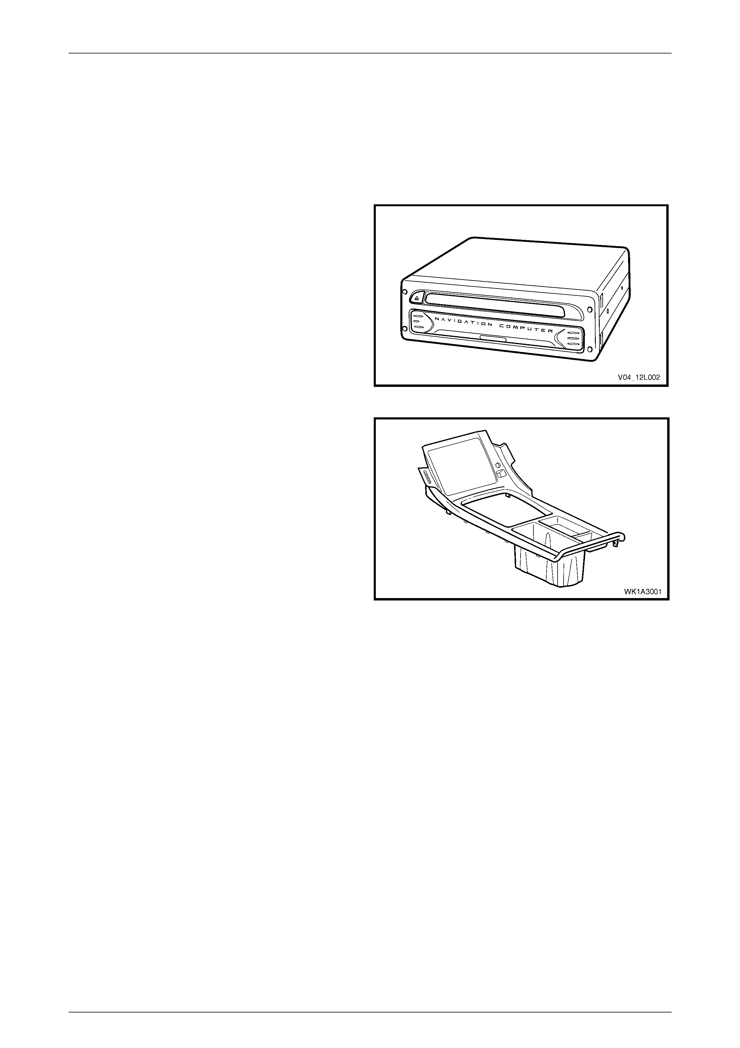
• The MY 2004 WK Series Navigation System has
received a running change to the system. As of 23
January 2004, vehicles fitted with the Navigation
System will have a new model processor installed. If
the vehicle was produced post 23 January 2004, or
has the processor module displayed fitted, refer to
Section 12L, in the MY 2004 VY and V2 service
information for diagnostic procedures.
For all other diagnostics and service operations, refer
to Section 12L Navigation System in the MY 2003 VY
and V2 Service Information.
Figure 12L – 1
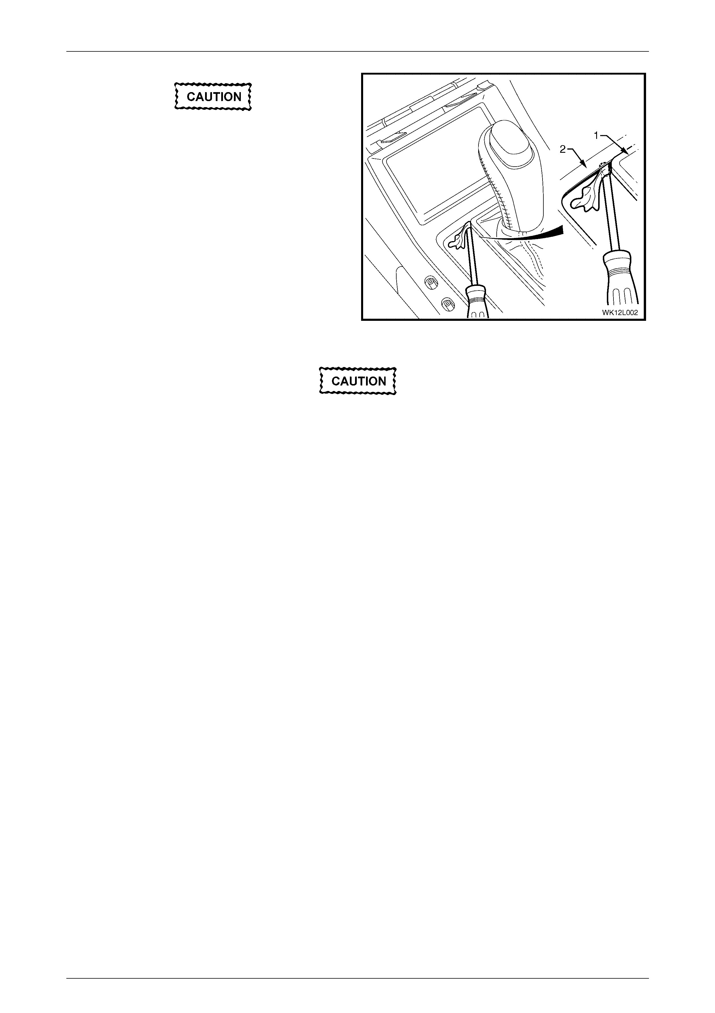
• The MY 2004 WK Series vehicle has a new console
cover assembly which incorporates the escutcheon for
the display assembly.
Figure 12L – 2

Navigation S ystem Page 12L–3
01–DEC–2002 Page 12L–3
2 Service Operations
2.1 References
Section 12L Navigation System in the MY 2003 VY & V2 Series Service Information, contains reference to other MY
2003 VY & V2 Series Sections. Due to different components and maintenance procedures, the following references must
be substituted for the corresponding reference in Secti on 12L Navigation System in the MY 2003 VY & V2 Series Service
Information.
Fuses, Relays and Wiring Harness
For all fuse, relay and wiring harness information, refer to Section 12O Fuses, Relays And Wiring Harnesses in the
MY 2004 WK Service Information.
Remote Control Assembly
When performing service operations on the remote control assembly, refer to 2.2 Console Cover Assemb ly in this
Section, in conjunction with MY 2003 VY and V2 Series Service Information.
Cockpit Navigation Wiring Harness
When performing service operations on the cockpit navigation wiring harness that requires removal of the display
assembly, refer to 2.2 Console C over Assembly in this Section and Section 1A3, INSTRUMENT PANEL AND CONSOLE
in the MY 2004 WK Service Information, in conjunction with MY 2003 VY and V2 Series Service Information.
GPS Antenna Assembly
When performing service operations on the GPS antenna assembly that requires removal of the rear window trim panel
assembly, refer to Section 1A8, 2.5 Rear Window Trim Panel Assembly, in the MY 2004 WK Service Information, in
conjunction with MY 2003 VY and V2 Series Service Information.
Navigation Display Assembly
When performing service operations on the navigation display assembly, refer to 2.2 Console C over Assem bly in this
Section, in conjunction with MY 2003 VY and V2 Series Service Information.
Navigation Wiring Harness
When performing service operations on the navigation wiring harness, refer to Section 1A7, 6.2 Rear Seat Cushion
Assembly and 6.4 Rear Seat – Back Assembly. Also, refer to Section 1A8, 2.4 SIDE SILL TRIM AND PLATE, in the
MY 2004 WK Series Service Information, in conjunction with MY 2003 VY and V2 Series Service Information.

Navigation S ystem Page 12L–4
01–DEC–2002 Page 12L–4
2.2 Console Cover Assembly
LT Section –
The console cover assembly for WK vehicles fitted with the satellite navigation system now includes an integrated
escutcheon for the display assembly. This service procedure must be used in conjunction with Section 12L Navigation
System in the MY 2003 VY and V2 Series Service Information.
Remote Control Assembly
Remove
1 Ensure that the ignition switch is in the OFF position.
2 Remove the following fuses from the passenger compartment fuse and relay panel assembly:
• Radio fuse F23.
• Radio cellular phone fuse F16.
Refer to Sect ion 12O , 1.1 Fus es for location details.
3 Remove the following fusible link form the engine compartment fuse and relay panel assembly:
• Lighting fusibl e link F102 .
Refer to Section 12O, 1.3 Fusible Links for location details.
4 Remove the radio assembly, refer to Sect ion 1A3, 3.6 Radio Assembly in the MY 2003 VY and V2 Series Service
Information.
5 Remove the instrument panel lower extension side trim and disconnect the navigation wiring harness from the
cockpit navigation wiring harness connector A35, refer to Section 12L, 3.2 Remote Control Assembly in the MY
2003 VY and V2 Series Service Information.
6 Gently prise the floor console cover assembly (1) from
the floor console (2) and unclip each of the six
fastener clips ( 3) at the points i ndic ated .
7 Disconnect the hazard warning switch connector (4)
and auxiliary switch connector (5) from underneath the
floor console cover assembly.
Figure 12L – 3
Navigation S ystem Page 12L–5
01–DEC–2002 Page 12L–5
To assist removal of the floor console cover,
wedge a flat blade screwdriver with the blade
wrapped with cloth between the transmission
selector assembly applique (1) and the floor
console cover (2) as shown. This will prevent
the selector assembly appliqué from getting
caught on the console cover when the
console cover is raised.
Figure 12L – 4
Do not pull or tug on the remote control
cradle wiring harne ss.
8 Tilt the back of the floor console cover up and feed the remote control cradle wiring harness and connector through
the aperture in the floor console cover assembly and remove the remote control presenter and cradle, refer to
Section 12L, 3.2 Remote Control Assembly in the MY 2003 VY and V2 Series Service Information.
9 Remove the floor console cover assembly.
Reinstall
Reinstallation of the remote control assembly is the reverse of the removal procedure.
Navigation Display Assembly
LT Section –
The navigation display assembly is located behind the floor console cover assembly.
Remove
1 Disconnect the remote control presenter and cradle from the floor console cover and remove the floor console
cover to gain access to the navigation display assembly, refer to 2.2 Console Cover Assembly, in this Section.
NOTE
The navigation wiring harness to cockpit
navigation wiring harness connector A35 does
not have to be disconnected if the remote control
assembly is not being remov e d.
2 Remove the display assembly, refer to Section 12L, 3.3 Display Assembly in the MY 2003 VY and V2 Series
Service Information.
Reinstall
Reinstallation of the navigation display assembly, including the remote control cradle with presenter, is the reverse of the
removal procedur e.