
Occupant Protection System Page 12M–1
Page 12M–1
Section 12M
Occupant Protection System
ATTENTION
Before performing any service operation or other procedure described in this Section, refer to Section 00
Warnings, Cautions and Notes for correct workshop practices with regard to safety and/or property damage.
1 General Information............................................................................................................................... 2
1.1 Driver's Seatbelt Buckle Warning Indicator Switch – LHD Only ........................................................................2
Driver's Seatbelt Buckle Warning Indicator Switch.............................................................................................2
Modes of Operation............................................................................................................................................2
Seatbelt Warning Indicator....................................................................................................................................2
Level 1 and 2 Circuit Diagram...............................................................................................................................3
Level 4 Circuit Diagram .........................................................................................................................................4
Level 5 Circuit Diagram .........................................................................................................................................5
2 Service Operations – Seatbelts............................................................................................................ 6
2.1 Driver's Seatbelt Buckle and Pretensioner Assembly - LHD..............................................................................6
Remove ...................................................................................................................................................................6
Reinstall ..................................................................................................................................................................6
2.2 Rear Seatbelt Assembly – Outboard ....................................................................................................................7
Remove ...................................................................................................................................................................7
Reinstall ..................................................................................................................................................................8
2.3 Rear Seatbelt and Seatbelt Buckle Assembly – Centre, Level 5........................................................................9
Remove ...................................................................................................................................................................9
Reinstall ................................................................................................................................................................10
3 Diagnosis.............................................................................................................................................. 11
3.1 General Description.............................................................................................................................................11
3.2 Driver's Seatbelt Buckle Warning Indicator Switch - LHD Levels 1, 2.............................................................12
Circuit Description...............................................................................................................................................13
Test Description...................................................................................................................................................13
Notes on the Diagnostic Chart............................................................................................................................13
Diagnostic Chart...................................................................................................................................................13
3.3 Driver's Seatbelt Buckle Warning Indicator Switch - LHD Level 4...................................................................15
Circuit Description...............................................................................................................................................16
Test Description...................................................................................................................................................16
Notes on the Diagnostic Chart............................................................................................................................16
Diagnostic Chart...................................................................................................................................................16
3.4 Driver's Seatbelt Buckle Warning Indicator Switch - LHD Level 5...................................................................18
Diagnostic Charts.................................................................................................................................................18
Circuit Description...............................................................................................................................................19
Test Description...................................................................................................................................................19
Notes on the Diagnostic Chart............................................................................................................................20
Diagnostic Chart...................................................................................................................................................20
4 Torque Wrench Specifications........................................................................................................... 22
5 Special Tools........................................................................................................................................ 23
Techline
Techline
Techline

Occupant Protection System Page 12M–2
Page 12M–2
1 General Information
With the following exceptions, MY 2004 WK Series Occupant Protection System information carries over from MY 2003
VY and V2 Series vehicles. For information not contained within this Section, refer to Section 12M Occupant Protection
System in the MY 2003 VY and V2 Series Service Information.
• Driver's seatbelt buckle warning indicator switch – LHD only
• Rear seatbelt assembly – outboard
• Rear seatbelt and seatbelt buckle assembly – centre, Level 5
1.1 Driver's Seatbelt Buckle Warning
Indicator Switch – LHD Only
Driver's Seatbelt Buckle Warning Indicator Switch
The driver’s seatbelt buckle is equipped with a seatbelt buckle warning indicator switch (Production Option WD4).
The purpose of the driver's seatbelt buckle warning indicator switch is to activate the seatbelt warning indicator located in
the instrument cluster assembly when the ignition is turned to the ON position with the driver's seatbelt disengaged from
the buckle.
When the driver's seatbelt is buckled, the seatbelt buckle warning indicator switch is in an open circuit condition and
when unbuckled the switch is in a closed circuit condition.
Modes of Operation
• If the driver's seatbelt is fastened in the buckle after the ignition switch is turned on, the seatbelt warning indicator
will extinguish and the chime (if activated) will turn off.
• If the driver's seatbelt is fastened in the buckle and then the ignition switch is turned on, the seatbelt warning
indicator will illuminate for four seconds and then extinguish.
• If the driver' seatbelt is not fastened in t he buckle and the igni tion switch turned on, the seatbelt w arnin g indic ator
will illuminate, staying on until the seatbelt is fastened or the ignition switch is turned off.
Or
After a 150 second time delay, the warning indicator will flash on and off along with a warning chime until the
driver's seatbelt is fastened or the ignition switch is turned off.
• If the driver's seatbelt is not fastened in the buckle and the vehicle travelling above 25 km/h, the warning indicator
will flash on and off. The rate of the chime sound increases and a warning message ‘FASTEN SEATBELT’ is
displayed on the Multi Function Display until the seatbelt is fastened.
Seatbelt Warning Indicator
The seatbelt warning indicator provides a visual reminder to fasten the driver's seatbelt.
The seatbelt warning indicator is located on the instrument cluster assembly and is illuminated when the ignition control
relay is energised and a ground circuit is completed to the instrument cluster assembly.
Occupant Protection System Page 12M–3
Page 12M–3
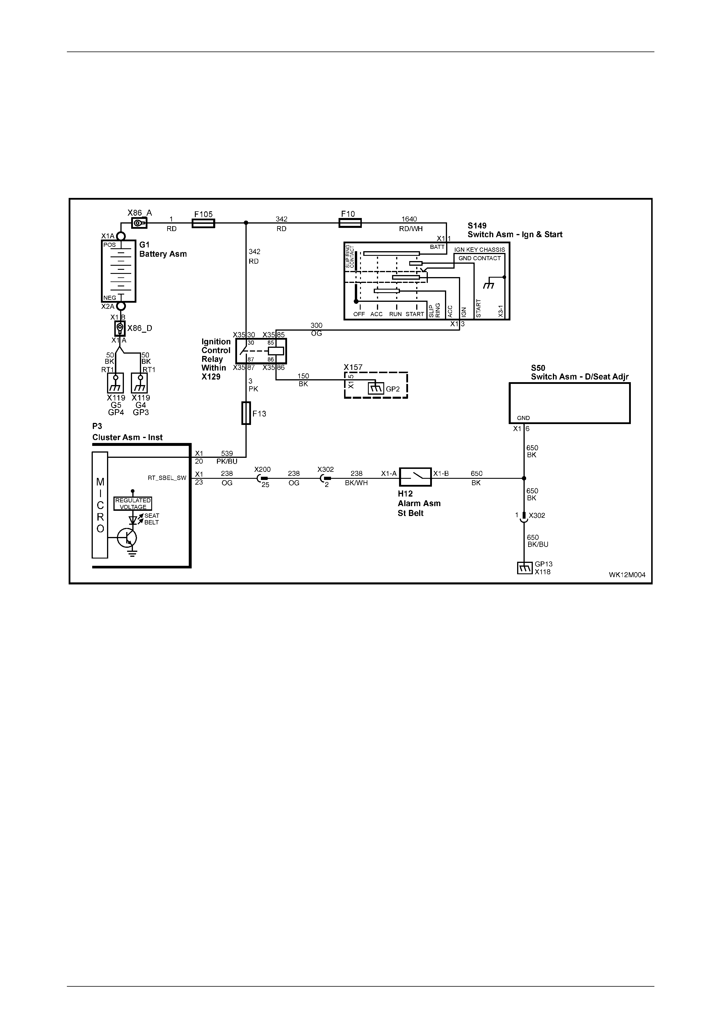
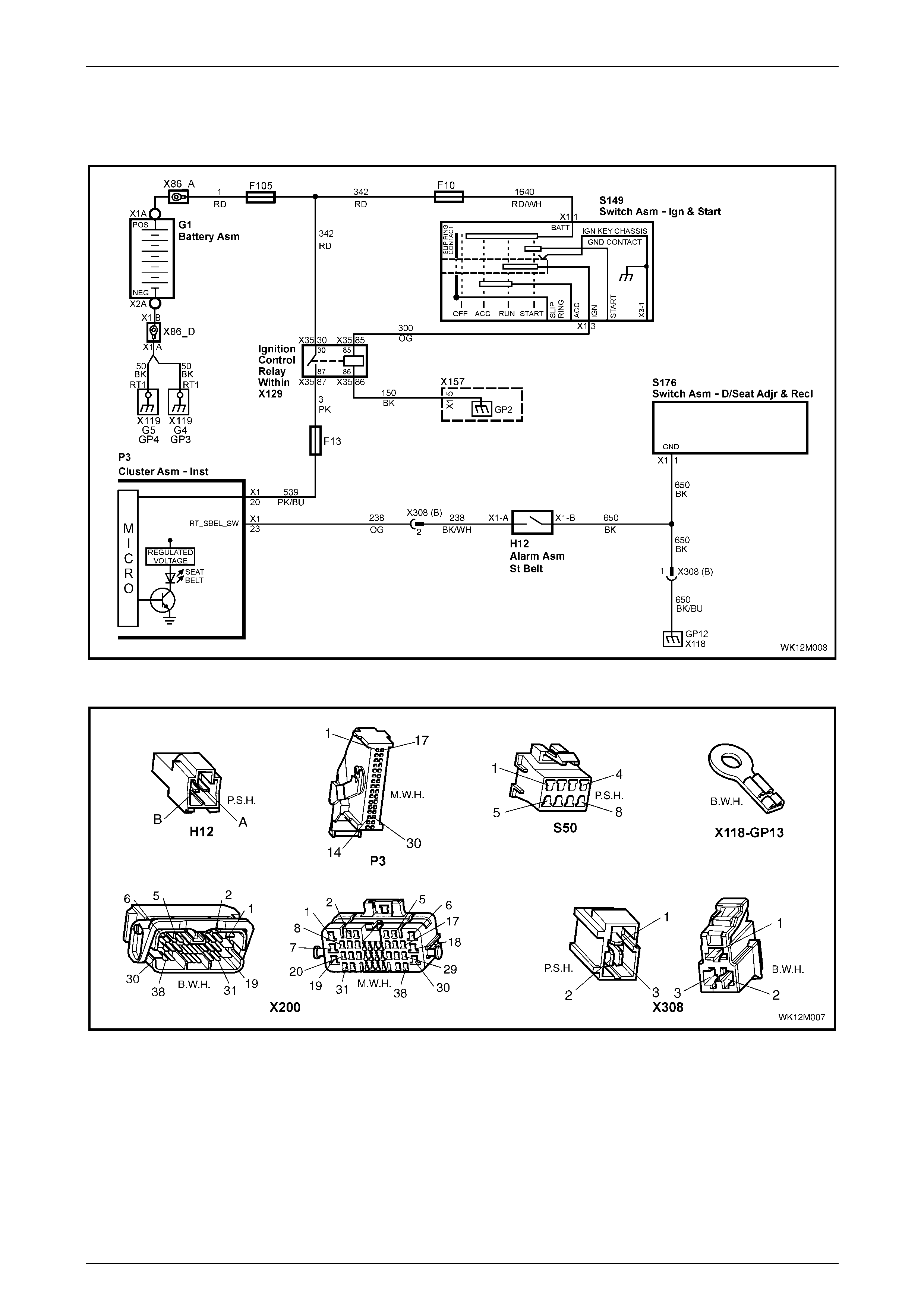
Level 1 and 2 Circuit Diagram
For vehicles with a driver's seatbelt buckle warning indicator switch, a three-pin connector is used instead of a two-pin
connector (X302).
The driver's seat adjuster switch assembly (S50) is used to provide the ground circuit for the instrument cluster assembly
connector P3 – X1 pin 23.
The driver's seatbelt buckle warning indicator switch connector H12 is located under the seat and is attached to the
driver's seatbelt buckle and pretensioner assembly via a pigtail harness.
Figure 12M – 1

Occupant Protection System Page 12M–4
Page 12M–4
Level 4 Circuit Diagram
For vehicles with a driver's seatbelt buckle warning indicator switch, a three-pin connector is used instead of a two-pin
connector (X308).
The driver's seat adjuster switch assembly (S176) is used to provide the ground circuit for the instrument cluster
assembly connector P3 – X1 pin 23.
The driver's seatbelt buckle warning indicator switch connector H12 is located under the seat and is attached to the
driver's seatbelt buckle and pretensioner assembly via a pigtail harness.
Figure 12M – 2
Occupant Protection System Page 12M–5
Page 12M–5
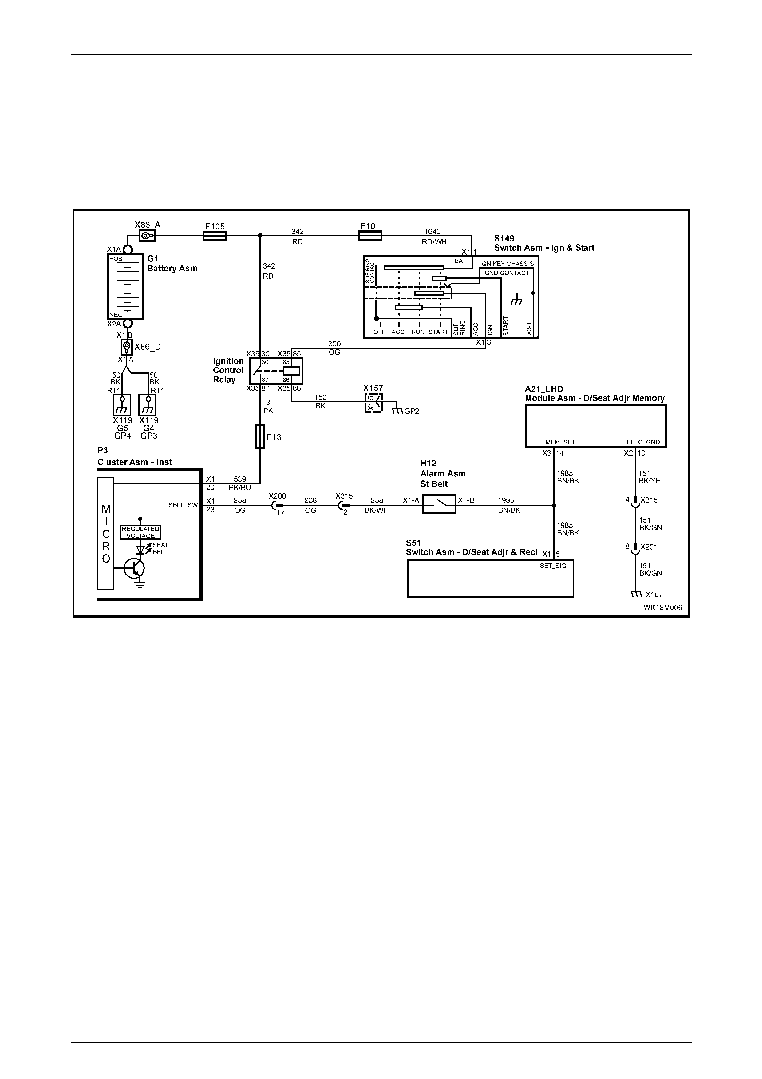
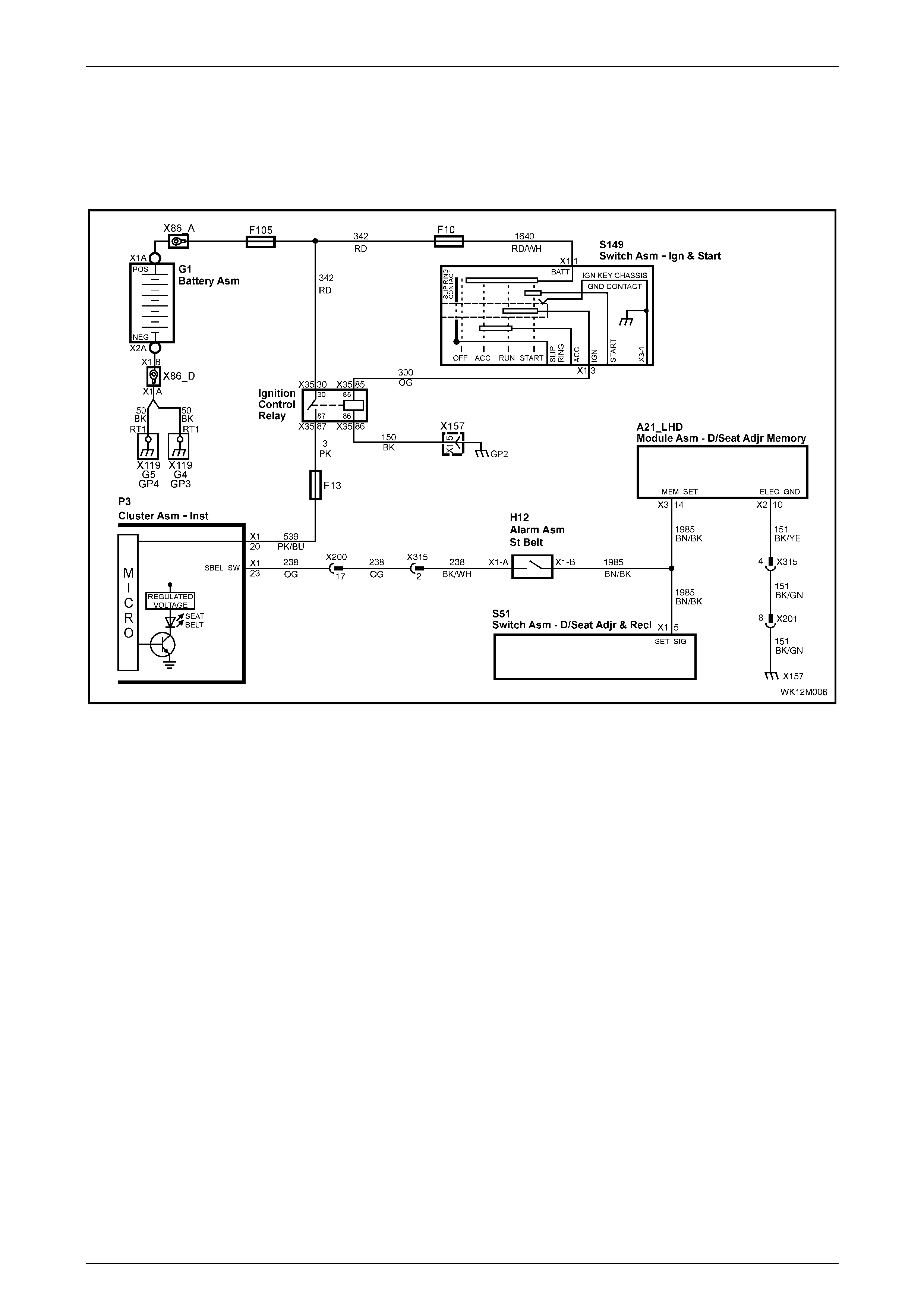
Level 5 Circuit Diagram
For vehicles with a driver's seatbelt buckle warning indicator switch, a three-pin connector is used instead of a two-pin
connector (X315).
The driver's seat memory module assembly (A21_LHD) is used to provide the ground circuit for the instrument cluster
assembly connector P3 – X1 pin 23.
The driver's seatbelt buckle warning indicator switch connector H12 is located under the seat and is attached to the
driver's seatbelt buckle and pretensioner assembly via a pigtail harness.
Figure 12M – 3

Occupant Protection System Page 12M–6
Page 12M–6
2 Service Operations – Seatbelts
2.1 Driver's Seatbelt Buckle and
Pretensioner Assembl y - LHD
LT Section No. 14-400
Remove
1 Disconnect the driver's seatbelt buckle warning indicator switch connector H12 – X1 from underneath the seat.
Remove the harness from any clips.
2 Remove the driver's seatbelt buckle and pretensioner assembly, refer to Section 12M, 3.4 Front Seatbelt Buckle
and Pretensioner Assembly in the MY 2003 VY and V2 Series Service Information.
Reinstall
Reinstallation of the driver's seatbelt buckle warning indicator switch is the reverse of the removal procedure, noting the
following:
1 Ensure that the seatbelt warning indicator operates correctly.
Occupant Protection System Page 12M–7
Page 12M–7
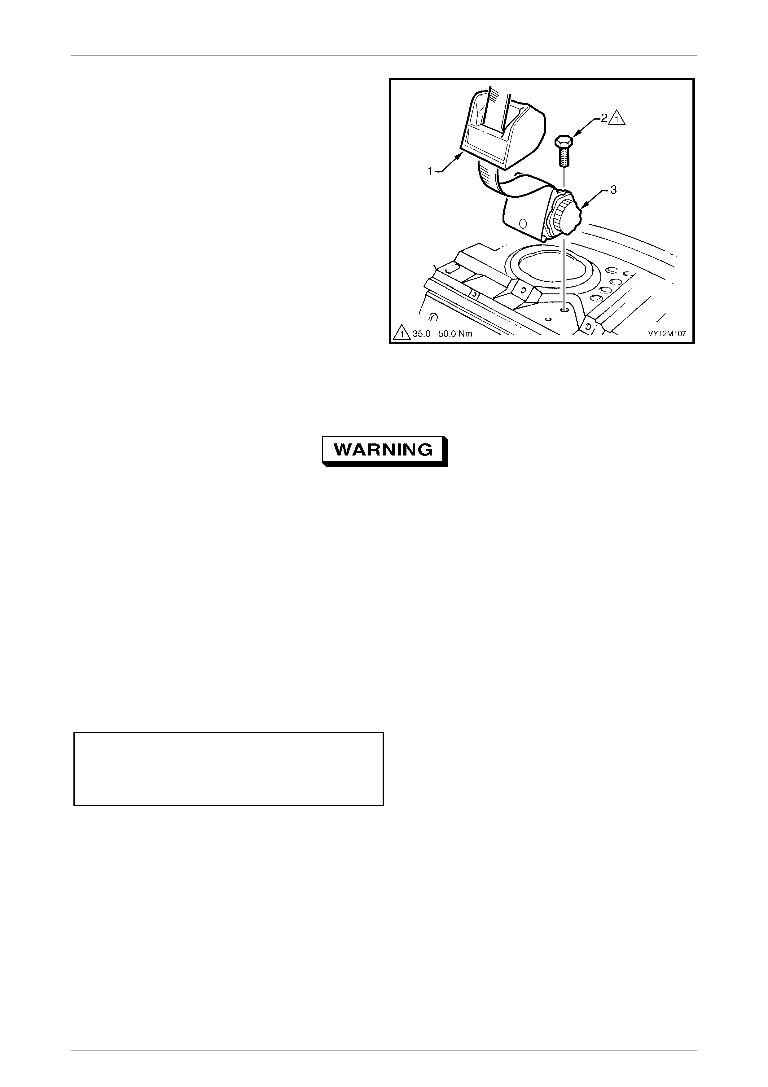
2.2 Rear Seatbelt Assembly – Outboard
LT Section No. – 14-425
Remove
1 Remove the rear seat cushion assembly, refer to
Section 1A7, 7.2 Rear Seat Cushion Assembly.
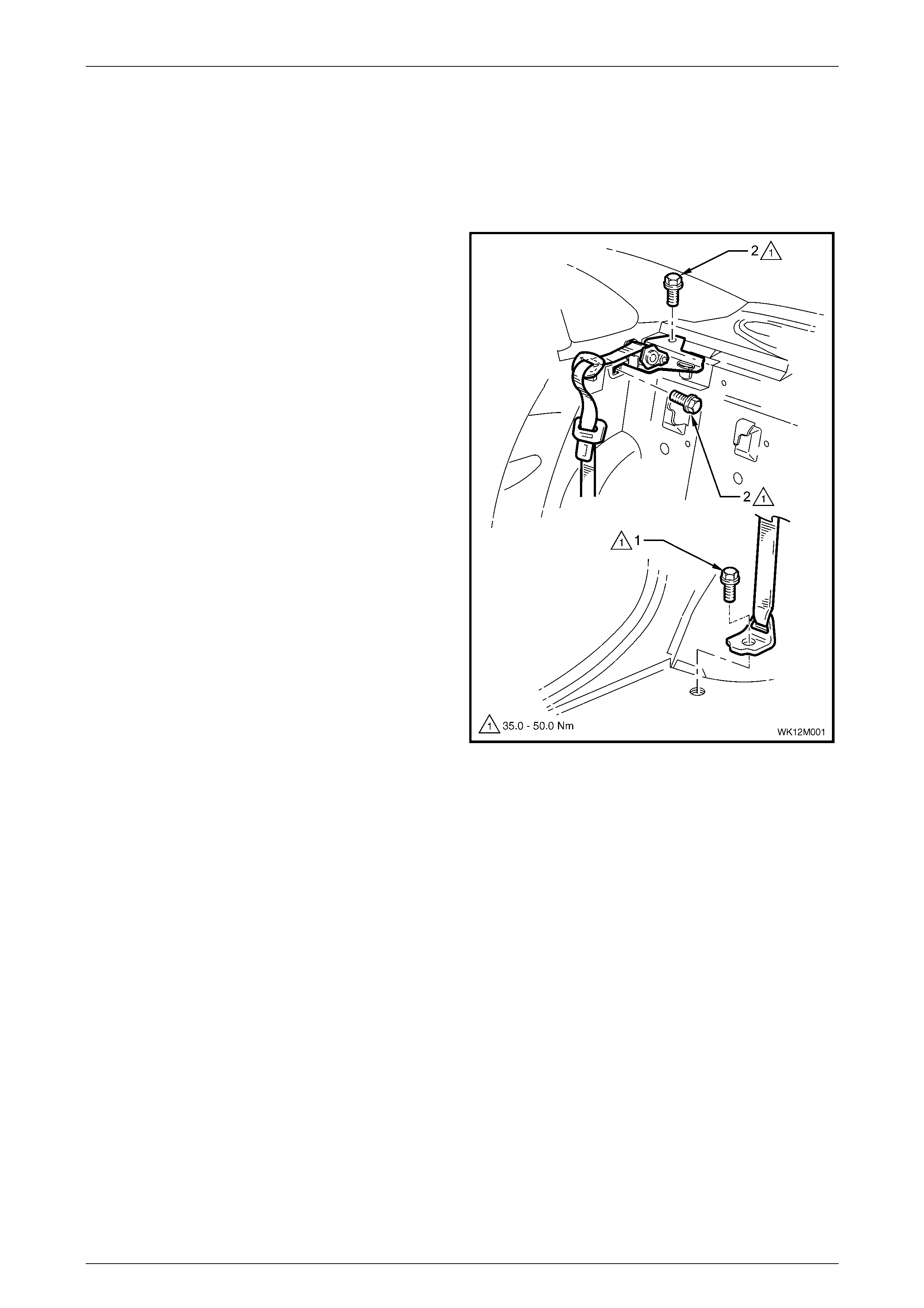
2 Remove the bolt (1) securing the lower outer seatbelt
anchor to the floor pan.
3 Remove the rear seat-back assembly, refer to
Section 1A7, 7.4 Rear Seat-back Assembly.
4 Remove the rear window trim panel assembly, refer to
Section 1A8, 2.5 Rear Window Trim Panel Assembly.
5 Remove the bolts (2), in two places, securing the rear
seatbelt retractor assembly to the vehicle body and
remove the seatbelt assembly.
6 If required, repeat Steps 1 to 5 for the opposite side of
the vehicle.
Figure 12M – 4

Occupant Protection System Page 12M–8
Page 12M–8
Reinstall
If reinstalling the same retractor assembly,
inspect the anchor plates and retractor
assembly for damage, and the webbing for
abrasions, fraying, cuts, etc. Replace the
seatbelt assembly and seatbelt buckle
assembly with new parts if any damage, etc.
is found.
Installation is the reverse of the removal procedure, noting the following.
1 Ensure that the seatbelt webbing is not twisted and the lower outer seatbelt anchor is installed in the correct
orientation, refer to Figure 12M – 4.
2 Ensure that the body harness and DVD harness (if fitted) is clear of the anchor plate.
3 Ensure that the threads of the lower outer seatbelt anchor bolts are adequately sealed with a commercially
available caul ki ng com pou nd or a non-har den ing sea ler.
4 To avoid cross-threading, hand tighten all seatbelt bolts a minimum of five turns before using tools.
5 Tighten the bolts to the specified torque.
Rear seatbelt retractor assembly
attaching bolt torque specification.......... 35.0 – 50.0 Nm
Rear seatbelt anchor attaching bolt
torque specification ................................35.0 – 50.0 Nm
6 Perform a functional check of the seatbelt to ensure correct operation.
Occupant Protection System Page 12M–9
Page 12M–9
2.3 Rear Seatbelt and Seatbelt Buckle
Assembly – Centre, Level 5
LT Section No. – 14-425
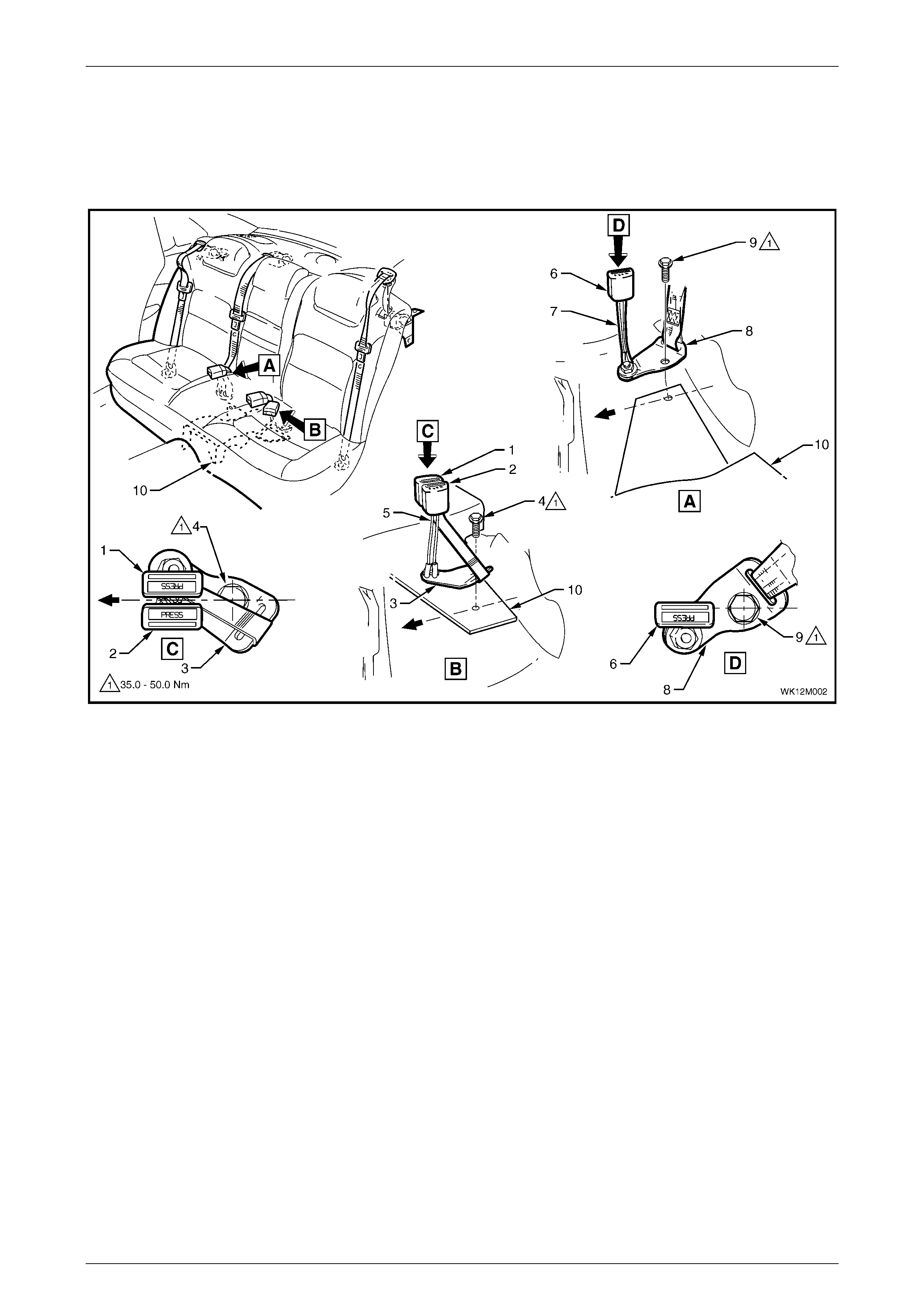
Figure 12M – 5
Legend
1 Middle Rear Seatbelt B uckl e
2 Left Rear Seatbelt Buckle
3 Left Rear Seatbelt Buckle Anchor
4 Left Rear Seatbelt Buckle Anchor Bolt
5 Left Rear Seatbelt Buck l e Cable Stalks
6 Right Rear Seatbelt B uckle
7 Right Rear Seatbelt B uckle Cabl e Stalk
8 Right Rear Seatbelt B uckle Anc hor
9 Right Rear Seatbelt B uckle Anc hor Bolt
10 Dead Pan for DVD bracket
Remove
1 Remove the rear seat cushion assembly, refer to Section 1A7, 7.2 Rear Seat Cushion Assembly.
2 Remove the bolt (4) securing the left rear seatbelt buckle anchor (3) and dead pan (10) to the vehicle, refer to
Figure 12M – 5.
3 Remove the rear window trim panel assembly, refer to Section 1A8, 2.5 Rear Window Trim Panel Assembly.
Occupant Protection System Page 12M–10
Page 12M–10
4 Lift off the insulator (1).
5 Remove the bolt (2) attaching the retractor
assembly (3) to the vehicle and remove the seatbelt
assembly.
Figure 12M – 6
Reinstall
If reinstalling the same retractor assembly,
inspect the anchor plates and retractor
assembly for damage, and the webbing for
abrasions, fraying, cuts, etc. Replace the
seatbelt assembly and seatbelt buckle
assembly with new parts if any damage, etc.
is found.
Reinstallation of the rear seatbelt and seatbelt buckle assembly is the reverse of the removal procedure, noting the
following:
1 Ensure that DVD harnesses are clear of the anchor plate and the dead pan.
2 Ensure that the threads of the seatbelt anchor bolts are adequately sealed with a commercially available caulking
compound or a non-hardening sealer.
3 To avoid cross-threading, hand tighten all seatbelt bolts a minimum of five turns before using tools.
4 Tighten the bolts to the specified torque.
Rear seatbelt retractor assembly
attaching bolt torque specification.......... 35.0 – 50.0 Nm
Rear seatbelt buckle anchor attaching
bolt torque specification.......................... 35.0 – 50.0 Nm
5 Perform a functional check of the seatbelt to ensure correct operation.

Occupant Protection System Page 12M–11
Page 12M–11
3 Diagnosis
3.1 General Description
When carrying out wiring checks as directed by the diagnostic charts, use the adaptors contained in connector test
adaptor kit KM-609 and test lead set KM-609-20. This will prevent any possibility of spreading or damaging wire harness
terminals and later on causing a system intermittent failure.
Ensure that at the completion of any diagnostic procedure, all diagnostic tools are removed and all components are
correctly reconnected.

Occupant Protection System Page 12M–12
Page 12M–12
3.2 Driver's Seatbelt Buckle Warning
Indicator Switch - LHD Levels 1, 2
Figure 12M – 7
Figure 12M – 8

Occupant Protection System Page 12M–13
Page 12M–13
Circuit Description
The purpose of the driver's seatbelt buckle warning indicator switch is to activate a seatbelt warning indicator located in
the instrument cluster assembly when the ignition is turned to the on position with the seatbelt disengaged from the
buckle.
When the seatbelt is buckled, the warning indicator switch is in an open circuit condition and when unbuckled the switch
is in a closed circuit condition.
TECH 2 can be used to check the driver's seatbelt buckle warning indicator switch operation, TECH 2 will only display
‘BUCKLED’ or ‘UN-BUCKLED’.
The seatbelt warning indicator will illuminate for four seconds when the ignition switch is turned to the on position,
irrespective of the status of the driver's seatbelt buckle warning indicator switch.
Test Description
The following numbers refer to step numbers in the following diagnostic chart.
1 Checks if the seatbelt indicator illuminates when the ignition is turned on. This can indicate either a faulty
instrument cluster assembly or a faulty power circuit.
2 Checks if the fault is an open circuit or a short circuit.
3 Checks if there is an intermittent fault in the circuit.
4 Checks if there is a faulty instrument cluster assembly or a faulty power circuit.
5 Checks the operation of the driver's seatbelt buckle warning indicator switch.
6 Checks continuity of circuit 650.
7 Checks continuity of circuit 238.
8 Checks the operation of the driver's seatbelt buckle warning indicator switch.
9 Checks for short circuit to ground in circuit 238.
Notes on the Diagnostic Chart
1 For all wiring harness fault diagnosis, refer to Section 12P Wiring Diagrams.
2 For wiring harness repairs, refer to Section 12P Wiring Diagrams.
3 Refer to Section 12O Fuses, Relays and Wiring Harnesses for harness routeing.
4 If at any time the fault is deemed to be intermittent, refer to Section 12P Wiring Diagrams.
Diagnostic Chart
Step Action Yes No
1 1 Install the TECH 2 to the DLC. Select BODY, INSTRUMENTS,
DATA DISPLAY and then INSTRUMENTS from the menu and
scroll down to DRIVERS SEATBELT.
2 Unbuckle the seatbel t.
3 Turn the ignition on with the engine off.
Does the seatbelt warning indicator illuminate?
Go to Step 2. Go to Step 4.
2 Does the TECH 2 display ‘UN-BUCKLED’? Go to Step 3. Go to Step 5.
3 1 Turn the ignition switch off.
2 Buckle the driver's seatbelt.
3 Turn the ignition on with the engine off.
Does the seatbelt warning indicator extinguish after four seconds and
does the TECH 2 display ‘BUCKLED’?
Check for an
intermittent fault,
refer to Note 4.
Go to Step 8.

Occupant Protection System Page 12M–14
Page 12M–14
Step Action Yes No
4 1 Check that the following telltale indicators illuminate when the
ignition is switched on with the engine off:
• ABS
• Brake
• SRS
• Generator
Do the above telltale indicators illuminate when the ignition switch is
turned on with the engine off?
Replace the
instrument cluster
assembly, refer to
Section 12C
Instruments.
Check continuity of
fuse F13,
fuse F105,
circuit 539, circui t 3
and circuit 342.
For additional
information, refer to
Section 12C
Instruments.
5 1 Turn the ignition off and disconnect connector H12.
2 Use a multimeter and Tool KM-609 at connector H12 to probe
the operation of the driver's seatbelt buckle warning indicator
switch. Refer to Note 1.
• Seatbelt unbuckled - continuity
• Seatbelt buckled - no continuity (open circuit)
Does the driver's seatbelt buckle warning indicator switch operate as
required?
Go to Step 6. Replace the driver's
seatbelt bu ckl e and
pretensioner
assembly, refer to
2.1 Driver's
Seatbelt Buckle and
Pretensioner
Assembly - LHD.
6 1 Turn the ignition off and disconnect connector H12.
2 Use a multimeter and Tool KM-609 to probe for continuity of
circuit 650 between connector H12-X1 pin B and ground point
GP13-X118. Refer to Note 1.
Is there continuity?
Go to Step 7. There is an open
circuit in circ uit 650.
Repair or replace
circuit 650 and/or
connector, refer to
Note 2.
7 1 Turn the ignition off and disconnect connector H12.
2 Use a multimeter and Tool KM-609 to probe for continuity of
circuit 238 between connector H12-X1 pin A and P3-X1 pin 23.
Refer to Note 1.
Is there continuity?
Replace the
instrument cluster
assembly, refer to
Section 12C, 2.3
Instrument Cluster
Assembly.
There is an open
circuit in circ uit 238.
Repair or replace
circuit 238 and/or
connector, refer to
Note 2.
8 1 Turn the ignition off and disconnect connector H12.
2 Use a multimeter and Tool KM-609 at connector H12 to probe
the operation of the driver's seatbelt buckle warning indicator
switch. Refer to Note 1.
• Seatbelt unbuckled - continuity
• Seatbelt buckled - no continuity (open circuit)
Does the driver's seatbelt buckle warning indicator switch operate as
required?
Go to Step 9. Replace the driver's
seatbelt bu ckl e and
pretensioner
assembly, refer to
2.1 Driver's
Seatbelt Buckle and
Pretensioner
Assembly - LHD.
9 1 Turn the ignition off and disconnect connector H12.
2 Use a multimeter and Tool KM-609 to probe for a short circuit to
ground in circuit 238 between connector H12-X1 pin A and
P3-X1 pin 23. Refer to Note 1.
Is there a short circuit to ground?
Repair or replace
circuit 238, refer to
Note 4.
Replace the
instrument cluster
assembly, refer to
Section 12C, 2.3
Instrument Cluster
Assembly.
Occupant Protection System Page 12M–15
Page 12M–15
3.3 Driver's Seatbelt Buckle Warning
Indicator Switch - LHD Level 4
Figure 12M – 9
Figure 12M – 10

Occupant Protection System Page 12M–16
Page 12M–16
Circuit Description
The purpose of the driver's seatbelt buckle warning indicator switch is to activate a seatbelt warning indicator located in
the instrument cluster assembly when the ignition is turned to the on position with the seatbelt disengaged from the
buckle.
When the seatbelt is buckled, the warning indicator switch is in an open circuit condition and when unbuckled the switch
is in a closed circuit condition.
TECH 2 can be used to check the driver's seatbelt buckle warning indicator switch operation, TECH 2 will only display
‘BUCKLED’ or ‘UN-BUCKLED’.
The seatbelt warning indicator will illuminate for four seconds when the ignition switch is turned to the on position,
irrespective of the status of the driver's seatbelt buckle warning indicator switch.
Test Description
The following numbers refer to step numbers in the following diagnostic chart.
1 Checks if the seatbelt indicator illuminates when the ignition is turned on. This can indicate either a faulty
instrument cluster assembly or a faulty power circuit.
2 Checks if the fault is an open circuit or a short circuit.
3 Checks if there is an intermittent fault in the circuit.
4 Checks if there is a faulty instrument cluster assembly or a faulty power circuit.
5 Checks the operation of the driver's seatbelt buckle warning indicator switch.
6 Checks continuity of circuit 650.
7 Checks continuity of circuit 238.
8 Checks the operation of the driver's seatbelt buckle warning indicator switch.
9 Checks for short circuit to ground in circuit 238.
Notes on the Diagnostic Chart
1 For all wiring harness fault diagnosis, refer to Section 12P Wiring Diagrams.
2 For wiring harness repairs, refer to Section 12P Wiring Diagrams.
3 Refer to Section 12O Fuses, Relays and Wiring Harnesses for harness routeing.
4 If at any time the fault is deemed to be intermittent, refer to Section 12P Wiring Diagrams.
Diagnostic Chart
Step Action Yes No
1 1 Install the TECH 2 to the DLC. Select BODY, INSTRUMENTS,
DATA DISPLAY and then INSTRUMENTS from the menu and
scroll down to DRIVERS SEATBELT.
2 Unbuckle the seatbel t.
3 Turn the ignition on with the engine off.
Does the seatbelt warning indicator illuminate?
Go to Step 2. Go to Step 4.
2 Does the TECH 2 display ‘UN-BUCKLED’? Go to Step 3. Go to Step 5.
3 1 Turn the ignition switch off.
2 Buckle the driver's seatbelt.
3 Turn the ignition on with the engine off.
Does the seatbelt warning indicator extinguish after four seconds and
does the TECH 2 display ‘BUCKLED’?
Check for an
intermittent fault,
refer to Note 4.
Go to Step 8.

Occupant Protection System Page 12M–17
Page 12M–17
Step Action Yes No
4 1 Check that the following telltale indicators illuminate when the
ignition is switched on with the engine off:
• ABS
• Brake
• SRS
• Generator
Do the above telltale indicators illuminate when the ignition switch is
turned on with the engine off?
Replace the
instrument cluster
assembly, refer to
Section 12C
Instruments.
Check continuity of
fuse F13,
fuse F105,
circuit 539, circui t 3
and circuit 342.
For additional
information, refer to
Section 12C
Instruments.
5 1 Turn the ignition off and disconnect connector H12.
2 Use a multimeter and Tool KM-609 at connector H12 to probe
the operation of the driver's seatbelt buckle warning indicator
switch. Refer to Note 1.
• Seatbelt unbuckled - continuity
• Seatbelt buckled - no continuity (open circuit)
Does the driver's seatbelt buckle warning indicator switch operate as
required?
Go to Step 6. Replace the driver's
seatbelt bu ckl e and
pretensioner
assembly, refer to
2.1 Driver's
Seatbelt Buckle and
Pretensioner
Assembly - LHD.
6 1 Turn the ignition off and disconnect connector H12.
2 Use a multimeter and Tool KM-609 to probe for continuity of
circuit 650 between connector H12-X1 pin B and ground point
GP12-X118. Refer to Note 1.
Is there continuity?
Go to Step 7. There is an open
circuit in circ uit 650.
Repair or replace
circuit 650 and/or
connector, refer to
Note 2.
7 1 Turn the ignition off and disconnect connector H12.
2 Use a multimeter and Tool KM-609 to probe for continuity of
circuit 238 between connector H12-X1 pin A and P3-X1 pin 23.
Refer to Note 1.
Is there continuity?
Replace the
instrument cluster
assembly, refer to
Section 12C, 2.3
Instrument Cluster
Assembly.
There is an open
circuit in circ uit 238.
Repair or replace
circuit 238 and/or
connector, refer to
Note 2.
8 1 Turn the ignition off and disconnect connector H12.
2 Use a multimeter and Tool KM-609 at connector H12 to probe
the operation of the driver's seatbelt buckle warning indicator
switch. Refer to Note 1.
• Seatbelt unbuckled - continuity
• Seatbelt buckled - no continuity (open circuit)
Does the driver's seatbelt buckle warning indicator switch operate as
required?
Go to Step 9. Replace the driver's
seatbelt bu ckl e and
pretensioner
assembly, refer to
2.1 Driver's
Seatbelt Buckle and
Pretensioner
Assembly - LHD.
9 1 Turn the ignition off and disconnect connector H12.
2 Use a multimeter and Tool KM-609 to probe for a short circuit to
ground in circuit 238 between connector H12-X1 pin A and
P3-X1 pin 23. Refer to Note 1.
Is there a short circuit to ground?
Repair or replace
circuit 238, refer to
Note 4.
Replace the
instrument cluster
assembly, refer to
Section 12C, 2.3
Instrument Cluster
Assembly.
Occupant Protection System Page 12M–18
Page 12M–18
3.4 Driver's Seatbelt Buckle Warning
Indicator Switch - LHD Level 5
Diagnostic Charts
Figure 12M – 11
Occupant Protection System Page 12M–19
Page 12M–19
Figure 12M – 12
Circuit Description
The purpose of the driver's seatbelt buckle warning indicator switch is to activate a seatbelt warning indicator located in
the instrument cluster assembly when the ignition is turned to the on position with the seatbelt disengaged from the
buckle.
When the seatbelt is buckled, the warning indicator switch is in an open circuit condition and when unbuckled the switch
is in a closed circuit condition.
TECH 2 can be used to check the driver's seatbelt buckle warning indicator switch operation, TECH 2 will only display
‘BUCKLED’ or ‘UN-BUCKLED’.
The seatbelt warning indicator will illuminate for four seconds when the ignition switch is turned to the on position,
irrespective of the status of the driver's seatbelt buckle warning indicator switch.
Test Description
The following numbers refer to step numbers in the following diagnostic chart.
1 Checks if the seatbelt indicator illuminates when the ignition is turned on. This can indicate either a faulty
instrument cluster assembly or a faulty power circuit.
2 Checks if the fault is an open circuit or a short circuit.
3 Checks if there is an intermittent fault in the circuit.
4 Checks if there is a faulty instrument cluster assembly or a faulty power circuit.
5 Checks the operation of the driver's seatbelt buckle warning indicator switch.
6 Checks continuity of circuit 151 and circuit 1985.
7 Checks continuity of the driver's seat memory module assembly between A21-X3 pin 14 and A21-X2 pin 10.
8 Checks continuity of circuit 238.
9 Checks the operation of the driver's seatbelt buckle warning indicator switch.
10 Checks for short circuit to ground in circuit 238.

Occupant Protection System Page 12M–20
Page 12M–20
Notes on the Diagnostic Chart
1 For all wiring harness fault diagnosis, refer to Section 12P Wiring Diagrams.
2 For wiring harness repairs, refer to Section 12P Wiring Diagrams.
3 Refer to Section 12O Fuses, Relays and Wiring Harnesses for harness routeing.
4 If at any time the fault is deemed to be intermittent, refer to Section 12P Wiring Diagrams.
Diagnostic Chart
Step Action Yes No
1 1 Install the TECH 2 to the DLC. Select BODY, INSTRUMENTS,
DATA DISPLAY and then INSTRUMENTS from the menu and
scroll down to DRIVERS SEATBELT.
2 Unbuckle the seatbel t.
3 Turn the ignition on with the engine off.
Does the seatbelt warning indicator illuminate?
Go to Step 2. Go to Step 4.
2 Does the TECH 2 display ‘UN-BUCKLED’? Go to Step 3. Go to Step 5.
3 1 Turn the ignition switch off.
2 Buckle the driver's seatbelt.
3 Turn the ignition on with the engine off.
Does the seatbelt warning indicator extinguish after four seconds and
does the TECH 2 display ‘BUCKLED’?
Check for an
intermittent fault,
refer to Note 4.
Go to Step 9.
4 1 Check that the following telltale indicators illuminate when the
ignition is switched on with the engine off:
• ABS
• Brake
• SRS
• Generator
Do the above telltale indicators illuminate when the ignition switch is
turned on with the engine off?
Replace the
instrument cluster
assembly, refer to
Section 12C
Instruments.
Check continuity of
fuse F13,
fuse F105,
circuit 539, circui t 3
and circuit 342.
For additional
information, refer to
Section 12C
Instruments.
5 1 Turn the ignition off and disconnect connector H12.
2 Use a multimeter and Tool KM-609 at connector H12 to probe
the operation of the driver's seatbelt buckle warning indicator
switch. Refer to Note 1.
• Seatbelt unbuckled - continuity
• Seatbelt buckled - no continuity (open circuit)
Does the driver's seatbelt buckle warning indicator switch operate as
required?
Go to Step 6. Replace the driver's
seatbelt bu ckl e and
pretensioner
assembly, refer to
2.1 Driver's
Seatbelt Buckle and
Pretensioner
Assembly - LHD.
6 1 Turn the ignition off and disconnect connector H12, A21-X2 and
A21-X3.
2 Use a multimeter and Tool KM-609 to probe for continuity of
circuit 1985 between connector H12-X1 pin B and connector
A21-X3 pin 14. Refer to Note 1.
3 Use a multimeter and Tool KM-609 to probe for continuity of
circuit 151 between connector A21-X2 pin 10 and ground point
X157. Refer to Note 1.
Is there continuity?
Go to step 7. There is an open
circuit in circuit 189 5
or circuit 151.
Repair or replace
circuit 1895,
circuit 151 and/or
connector, refer to
Note 2.

Occupant Protection System Page 12M–21
Page 12M–21
Step Action Yes No
7 1 Turn the ignition off and disconnect connector H12, A21-X2 and
A21-X3.
2 Use a multimeter and Tool KM-609 to probe for continuity of the
driver's seat memory module assembly between A21-X3 pin 14
and A21-X2 pin 10.
Is there continuity?
Go to step 8. There is an open
circuit in the driver's
seat memory
module assembly.
Replace the driver's
seat memory
module assembly,
refer to Section 1A7,
4.12 Seat Memory
Module.
8 1 Turn the ignition off and disconnect connector H12.
2 Use a multimeter and Tool KM-609 to probe for continuity of
circuit 238 between connector H12-X1 pin A and P3-X1 pin 23.
Refer to Note 1.
Is there continuity?
Replace the
instrument cluster
assembly, refer to
Section 12C, 2.3
Instrument Cluster
Assembly.
There is an open
circuit in circ uit 238.
Repair or replace
circuit 238 and/or
connector. Refer to
Note 2.
9 1 Turn the ignition off and disconnect connector H12.
2 Use a multimeter and Tool KM-609 at connector H12 to probe
the operation of the driver's seatbelt buckle warning indicator
switch. Refer to Note 1.
• Seatbelt unbuckled - continuity
• Seatbelt buckled - no continuity (open circuit)
Does the driver's seatbelt buckle warning indicator switch operate as
required?
Go to Step 10. Replace the driver's
seatbelt bu ckl e and
pretensioner
assembly, refer to
2.1 Driver's
Seatbelt Buckle and
Pretensioner
Assembly - LHD.
10 1 Turn the ignition off and disconnect connector H12.
2 Use a multimeter and Tool KM-609 to probe for a short circuit to
ground in circuit 238 between connector H12-X1 pin A and
P3-X1 pin 23. Refer to Note 1.
Is there a short circuit to ground?
Repair or replace
circuit 238, refer to
Note 4.
Replace the
instrument cluster
assembly, refer to
Section 12C, 2.3
Instrument Cluster
Assembly.

Occupant Protection System Page 12M–22
Page 12M–22
4 Torque Wrench Specifications
Rear seatbelt retractor assembly attaching bolt.........................35.0 – 50.0 Nm
Rear seatbelt anchor attaching bolt...........................................35.0 – 50.0 Nm
Rear seatbelt buckle anchor attaching bolt................................35.0 – 50.0 Nm
Occupant Protection System Page 12M–23
Page 12M–23
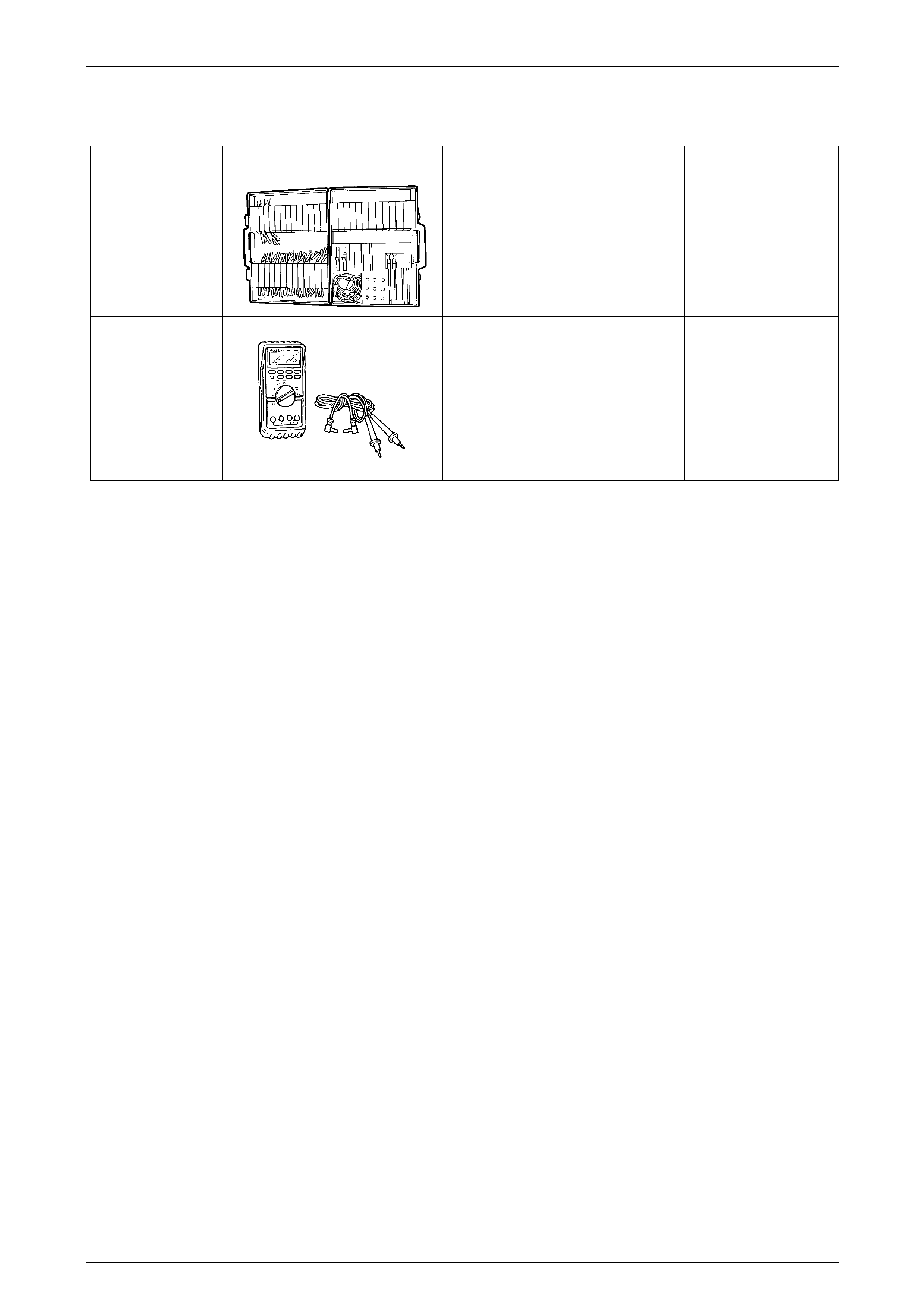
5 Special Tools
Tool Number Illustration Description Tool Classification
KM-609
(J35616-A)
ELECTRONIC KIT
Used in conjunction with a multimeter
for measuring voltages and
resistances without damagi ng wiring
harness con nec tors .
Desirable
J213200
DIGITAL MULTIMETER
Used for various measurement
functions. Must have at least 10 MΩ
input impedance and be capable of
reading capacitance.
Commercially available.
Previously released.
Available