
Fuses, Relays and Wi ring Harnesse s Page 12O–1
Page 12O–1
Section 12O
Fuses, Relays and Wiring Harne sses
ATTENTION
Before performing any Service Operation or other procedure described in this section, refer to Section 00
Warnings, Cautions and Notes for correct workshop practices with regard to safety and/or property damage.
1 General Information............................................................................................................................... 5
1.1 Fuses.......................................................................................................................................................................5
1.2 Circuit Breakers......................................................................................................................................................8
1.3 Fusible Links ..........................................................................................................................................................9
1.4 Relays....................................................................................................................................................................11
Passenger Compartment Relays ........................................................................................................................11
Engine Compartment Relays...............................................................................................................................12
1.5 Diodes ...................................................................................................................................................................13
1.6 Wiring Harnesses.................................................................................................................................................14
1.7 Wiring Harness Connectors................................................................................................................................15
1.8 Electronic Control Device Locations..................................................................................................................16
2 Service Operations.............................................................................................................................. 21
3 Wiring Installation Diagrams – Right-hand Drive............................................................................. 22
3.1 Battery Wiring Harness – 1..................................................................................................................................22
Battery and ABS...................................................................................................................................................22
3.2 Battery Wiring Harness – 2..................................................................................................................................23
V6 Engine..............................................................................................................................................................23
3.3 Battery Wiring Harness – 3..................................................................................................................................25
Gen III V8 Engine..................................................................................................................................................25
3.4 Powertrain Harness – 1........................................................................................................................................26
V6 Engine and V6 Supercharged Engine ...........................................................................................................26
3.5 Powertrain Harness – 2........................................................................................................................................27
V6 Normally Aspirated Engine............................................................................................................................27
3.6 Powertrain Harness – 3........................................................................................................................................28
V6 Engine With Air-conditioning or Electronic Climate Control......................................................................28
3.7 Powertrain Harness – 4........................................................................................................................................29
V6 Engine With Air-conditioning or Electronic Climate Control......................................................................29
3.8 Powertrain Harness – 5........................................................................................................................................30
V6 Engine..............................................................................................................................................................30
3.9 Powertrain Harness – 6........................................................................................................................................31
V6 Engine..............................................................................................................................................................31
3.10 Powertrain Harness – 7........................................................................................................................................32
V6 Supercharged Engine.....................................................................................................................................32
3.11 Powertrain Harness – 8........................................................................................................................................33
V6 Supercharged Engine With Air-conditioning or Electronic Climate Control.............................................33
3.12 Powertrain Harness – 9........................................................................................................................................34
V6 Supercharged Engine.....................................................................................................................................34
3.13 Powertrain Harness – 10......................................................................................................................................35
Gen III V8 Engine..................................................................................................................................................35
3.14 Powertrain Harness – 11......................................................................................................................................36
Gen III V8 Engine..................................................................................................................................................36
3.15 Powertrain Harness – 12......................................................................................................................................37
Gen III V8 Engine..................................................................................................................................................37

Fuses, Relays and Wi ring Harnesse s Page 12O–2
Page 12O–2
3.16 Powertrain Harness – 13......................................................................................................................................38
Gen III V8 Engine..................................................................................................................................................38
3.17 Powertrain Harness – 14......................................................................................................................................39
Gen III V8 Engine..................................................................................................................................................39
3.18 Powertrain Harness – 15......................................................................................................................................40
Gen III V8 Engine..................................................................................................................................................40
3.19 Powertrain Harness – 16......................................................................................................................................41
V6 Engine and V6 Supercharged Engine ...........................................................................................................41
3.20 Powertrain Harness – 17......................................................................................................................................42
Gen III V8 Engine..................................................................................................................................................42
3.21 Powertrain Harness – 18......................................................................................................................................43
Gen III V8 Engine..................................................................................................................................................43
3.22 Main Wiring Harness – 1......................................................................................................................................44
Engine Compartment – RHD ...............................................................................................................................44
3.23 Main Wiring Harness – 2......................................................................................................................................45
Protector Assembly, Cruise Control and Engine Harness Connectors ..........................................................45
3.24 Main Wiring Harness – 3......................................................................................................................................46
Under Hood Fuse & Relay P a nel and Wiper Motor Connectors.......................................................................46
3.25 Main Wiring Harness – 4......................................................................................................................................47
Front Lamps, Body Earth and Washer Pump Connectors................................................................................47
3.26 Main Wiring Harness – 5......................................................................................................................................48
Headlamp, Park Lamp and Turn Indicator Connectors.....................................................................................48
3.27 Main Wiring Harness – 6......................................................................................................................................49
Ambient Sensor, Air-conditioning Fan and Theft Deterrent Connectors........................................................49
3.28 Main Wiring Harness – 7......................................................................................................................................50
Ambient Sensor, Air-conditioning Fan and Theft Deterrent Connectors........................................................50
3.29 Main Wiring Harness – 8......................................................................................................................................51
Cornering Lamp, Fog Lamp and Horn Connectors...........................................................................................51
3.30 Main Wiring Harness – 9......................................................................................................................................52
Cockpit Module – RHD.........................................................................................................................................52
3.31 Main Wiring Harness – 10....................................................................................................................................54
Cockpit Module – RHD........................................................................................................... ..............................54
3.32 Main Wiring Harness – 11....................................................................................................................................55
Cockpit Module – RHD........................................................................................................... ..............................55
3.33 Main Wiring Harness – 12....................................................................................................................................57
Fuse Block and Body Control Module – RHD....................................................................................................57
3.34 Main Wiring Harness – 13....................................................................................................................................58
Steering Column – RHD.......................................................................................................................................58
3.35 Main Wiring Harness – 14....................................................................................................................................59
Ignition Lock and Theft Deterrent Receiver.......................................................................................................59
3.36 Main Wiring Harness – 15....................................................................................................................................60
Cruise Control, Stop Lamp Switches, Data Link Connector and Stepwell Lamps – RHD..............................60
3.37 Main Wiring Harness – 16....................................................................................................................................61
Inside Air Temperature Sensor & Accessory Jack – RHD................................................................................61
3.38 Main Wiring Harness – 17....................................................................................................................................62
Instrument Cluster Assembly..............................................................................................................................62
3.39 Main Wiring Harness – 18....................................................................................................................................63
Air-conditioning and Heating Controls...............................................................................................................63
3.40 Main Wiring Harness – 19....................................................................................................................................64
Radio Assembly and Instrument Panel Facia Trim Switches and Connectors – RHD...................................64
3.41 Main Wiring Harness – 20....................................................................................................................................66
Passenger Side Airbag Wiring – RHD ................................................................................................................66
3.42 Main Wiring Harness – 21....................................................................................................................................68
Light Sensor & Key Receiver and Instrument Panel Speaker..........................................................................68
3.43 Main Wiring Harness – 22....................................................................................................................................69
Radio Antenna Amplifier and Heating, Ventilation & Air-conditioner Connectors – RHD.............................69
3.44 Main Wiring Harness – 23....................................................................................................................................70
Instrument Panel Compartment – RHD..............................................................................................................70
3.45 Main Wiring Harness – 24....................................................................................................................................71
Transmission and SIR Sensing Diagnostic Module Connectors – RHD .........................................................71

Fuses, Relays and Wi ring Harnesse s Page 12O–3
Page 12O–3
3.46 Main Wiring Harness – 25....................................................................................................................................73
Transmission Selector and Floor Console Connectors – RHD........................................................................73
3.47 Main Wiring Harness – 26....................................................................................................................................74
Stop Lamp, Traction and Cruise Control Release Connectors – RHD ............................................................74
3.48 Main Wiring Harness – 27....................................................................................................................................75
Telematics System – RHD ...................................................................................................................................75
3.49 Main Wiring Harness – 28....................................................................................................................................77
Front and Rear Cigar Lighter and Accessory Power Connector......................................................................77
3.50 Radio Power Antenna Assembly Wiring – RHD.................................................................................................78
3.51 Radio Amplifier and Antenna Wiring – 1............................................................................................................80
3.52 Radio Amplifier and Antenna Wiring – 2............................................................................................................81
Level 1, 2, 3 and 4.................................................................................................................................................81
3.53 Radio Amplifier and Antenna Wiring – 3............................................................................................................82
Level 5...................................................................................................................................................................82
3.54 Navigation System Assembly – 1 – RHD............................................................................................................84
3.55 Navigation System Assembly – 2 – RHD............................................................................................................85
3.56 Video Player System and Wiring – 1...................................................................................................................87
3.57 Video Player System and Wiring – 2...................................................................................................................89
3.58 Sunroof System and Wiring ................................................................................................................................91
3.59 Body and Roof Wiring Harnesses – 1.................................................................................................................93
Interior – RHD.......................................................................................................................................................93
3.60 Body and Roof Wiring Harnesses – 2.................................................................................................................94
Interior – RHD.......................................................................................................................................................94
3.61 Body and Roof Wiring Harnesses – 3.................................................................................................................95
Interior – RHD.......................................................................................................................................................95
3.62 Body and Roof Wiring Harnesses – 4.................................................................................................................96
Interior...................................................................................................................................................................96
3.63 Body and Roof Wiring Harnesses – 5.................................................................................................................97
Dome and Rear Passenger Compartment Lamps.............................................................................................97
3.64 Body and Roof Wiring Harnesses – 6.................................................................................................................98
Parcel Shelf and Rear Compartment Lamp........................................................................................................98
3.65 Body and Roof Wiring Harnesses – 7.................................................................................................................99
Speakers and Rear Roof Control Units..............................................................................................................99
3.66 Body and Roof Wiring Harnesses – 8...............................................................................................................101
Rear Compartment, Fuel Tank and ABS...........................................................................................................101
3.67 Body and Roof Wiring Harnesses – 9...............................................................................................................102
Fuel Pump Module – V6 Supercharged Engine...............................................................................................102
3.68 Body and Roof Wiring Harnesses – 10.............................................................................................................103
Rear Compartment – Level 4.............................................................................................................................103
3.69 Body and Roof Wiring Harnesses – 11.............................................................................................................105
Rear Compartment – Level 5.............................................................................................................................105
3.70 Body and Roof Wiring Harnesses – 12.............................................................................................................107
Rear Compartment Lid.......................................................................................................................................107
3.71 Body and Roof Wiring Harnesses – 13.............................................................................................................108
Reverse Parking Aid ..........................................................................................................................................108
3.72 Body Wiring Harness – 1...................................................................................................................................109
LPG – RHD..........................................................................................................................................................109
3.73 Body Wiring Harness – 2...................................................................................................................................110
Level Ride System..............................................................................................................................................110
3.74 Door Wiring Harness – 1....................................................................................................................................112
Front Door – RHD – Level 4...............................................................................................................................112
3.75 Door Wiring Harness – 2....................................................................................................................................114
Front Door – RHD – Level 5...............................................................................................................................114
3.76 Door Wiring Harness – 3....................................................................................................................................116
Rear Door............................................................................................................................................................116
4 Wiring Installation Diagrams – Left-hand Drive.............................................................................. 117
4.1 Main Wiring Harness – 1....................................................................................................................................117
Barometric Pressure Sensor.............................................................................................................................117

Fuses, Relays and Wi ring Harnesse s Page 12O–4
Page 12O–4
4.2 Main Wiring Harness – 2....................................................................................................................................118
Engine Compartment.........................................................................................................................................118
4.3 Main Wiring Harness – 3....................................................................................................................................119
Protector Assembly, Cruise Control and Engine Harness Connectors ........................................................119
4.4 Main Wiring Harness – 4....................................................................................................................................120
Cockpit Module –Without Cruise Control.........................................................................................................120
4.5 Main Wiring Harness – 5....................................................................................................................................122
Cockpit Module –With Cruise Control..............................................................................................................122
4.6 Main Wiring Harness – 6....................................................................................................................................124
Cockpit Module...................................................................................................................................................124
4.7 Main Wiring Harness – 7....................................................................................................................................125
Cockpit Module...................................................................................................................................................125
4.8 Main Wiring Harness – 8....................................................................................................................................127
Cockpit Module...................................................................................................................................................127
4.9 Main Wiring Harness – 9....................................................................................................................................129
Fuse & Relay Panel and Body Control Module................................................................................................129
4.10 Main Wiring Harness – 10..................................................................................................................................130
Steering Column.................................................................................................................................................130
4.11 Main Wiring Harness – 11..................................................................................................................................131
Cruise Control, Stop Lamp Switches, Data Link Connector & Stepwell Lamps...........................................131
4.12 Main Wiring Harness – 12..................................................................................................................................132
Inside Air Temperature Sensor & Accessory Jack ..........................................................................................132
4.13 Main Wiring Harness – 13..................................................................................................................................133
Instrument Panel Facia Trim Switches – Level 1.............................................................................................133
4.14 Main Wiring Harness – 14..................................................................................................................................134
Radio Assembly and Instrument Panel Facia Trim Switches and Connectors – Level 2, 3 & 5..................134
4.15 Main Wiring Harness – 15..................................................................................................................................135
Passenger Side Airbag Wiring..........................................................................................................................135
4.16 Main Wiring Harness – 16..................................................................................................................................136
Amplifier Assembly Radio Antenna, Heating, Ventilation & Air-conditioner Connectors ...........................136
4.17 Main Wiring Harness – 17..................................................................................................................................137
Instrument Panel Compartment........................................................................................................................137
4.18 Main Wiring Harness – 18..................................................................................................................................138
Transmission & SIR Sensing Diagnostic Module Connectors.......................................................................138
4.19 Main Wiring Harness – 19..................................................................................................................................140
Transmission Selector and Floor Console Connectors..................................................................................140
4.20 Main Wiring Harness – 20..................................................................................................................................141
Stop Lamp, Traction and Cruise Control Release Connectors......................................................................141
4.21 Body and Roof Wiring Harnesses – 1...............................................................................................................142
Interior.................................................................................................................................................................142
4.22 Body and Roof Wiring Harnesses – 2...............................................................................................................143
Interior.................................................................................................................................................................143
4.23 Body and Roof Wiring Harnesses – 3...............................................................................................................145
Fuel Tank Filler Door Lock ................................................................................................................................145
4.24 Radio Power Antenna Assembly Wiring ..........................................................................................................146
4.25 Door Wiring Harness – 1....................................................................................................................................148
Front Door – Level 1, 2 and 3 ............................................................................................................................148
4.26 Door Wiring Harness – 2....................................................................................................................................150
Front Door – Level 5...........................................................................................................................................150
Fuses, Relays and Wi ring Harnesse s Page 12O–5
Page 12O–5
1 General Information
All MY 2004 WK Series electrical circuits are protected against damage that might occur due to short circuits or
overloads in the wiring system by fuses, circuit breakers, fusible links and relays.
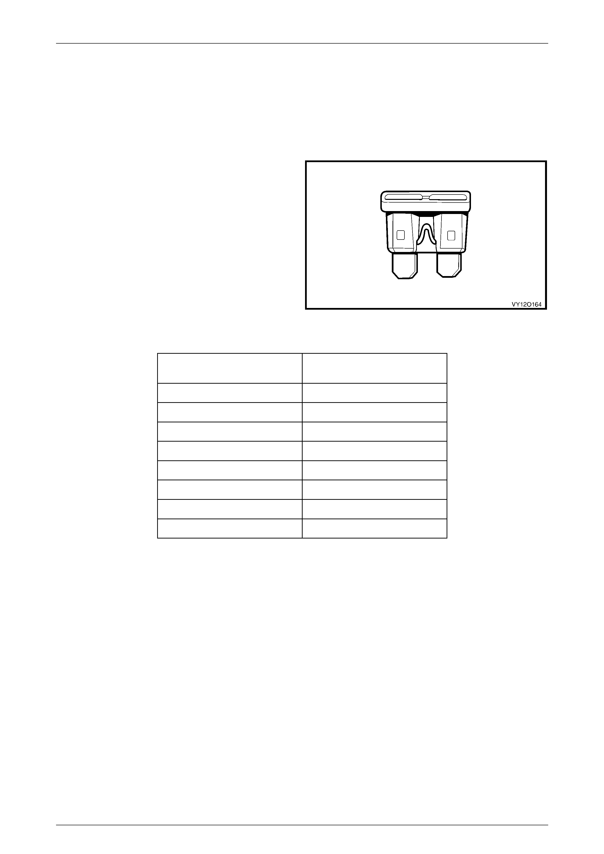
1.1 Fuses
Fuses are a blade type mini construction, with the current
rating in amps indicated on the top of the fuse assembly,
above the element, or identified by the plastic body colour of
the fuse. The fuse current ratings and corresponding colour
are listed in the following table.
Figure 12O – 1
Current Rating
(Amps) Fuse Colour
3 Violet
5 Tan
7.5 Brown
10 Red
15 Blue
20 Yellow
25 White
30 Green
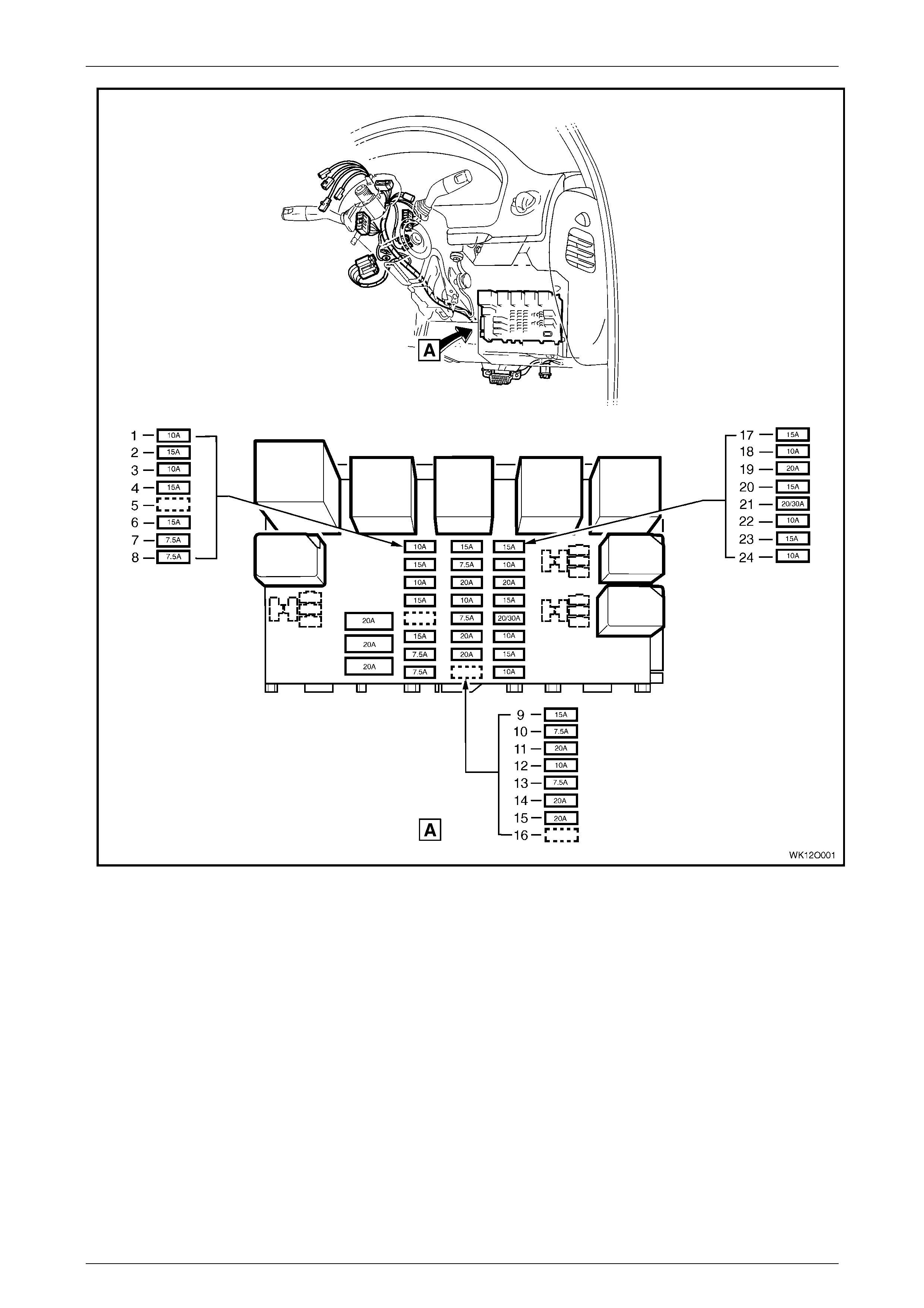
Fuses are located in two positions on MY 2004 WK series. One group is located in the passenger compartment fuse
and relay panel assembly. Refer to Figure 12O – 2. A label on the inside of the instrument panel lower cover indicates
the circuits protected by each fuse.
Fuses, Relays and Wi ring Harnesse s Page 12O–6
Page 12O–6
Figure 12O – 2
Legend
1 F4 – Park Lamps Fuse (10A)
2 F5 – Stop Lamps Fuse (15A)
3 F6 – Interior Illumination Fuse (10A)
4 F7 – Hazard Lamps/Antenna Drive via BCM Fuse (15A)
5 F8 – Spare
6 F9 – Horn Fuse (15A)
7 F10 – Ignition Fuse (7.5A)
8 F11 – Instrument Illuminat i on Fuse (7.5A)
9 F12 – Turn Signals & Back-up Lamps Fuse (15A)
10 F13 – ECC, Trip Computer, Instrum ents & Telematics Fuse
(7.5A)
11 F14 – Cigar Lighter Fuse (20A)
12 F15 – Cruise, Power Mirrors & Level Ride Fuse (10A)
13 F16 – Radio, MFD, Navigation & Cell Phone Fuse (7.5A)
14 F17 – Accessory Socket Fuse (20A)
15 F18 – Wiper Washer Fuse (20A)
16 F19 – Spare
17 F20 – Power Locks, Power Wi ndows & Theft Horn Fuse
(15A)
18 F21 – Instruments & Climate Control Fuse (10A)
19 F22 – Heated Rear Window Fuse (20A)
20 F23 – Radio, Cell Phone & Navigation Fuse (15A)
21 F24 – Sub-woofer Amplifier Fuse (20A) [Level 5 - 30A]
22 F25 – Entertainment System Fuse (10A)
23 F26 – SRS Fuse (15A)
24 F27 – Anti-lock Brakes Fuse (10A)
Fuses, Relays and Wi ring Harnesse s Page 12O–7
Page 12O–7
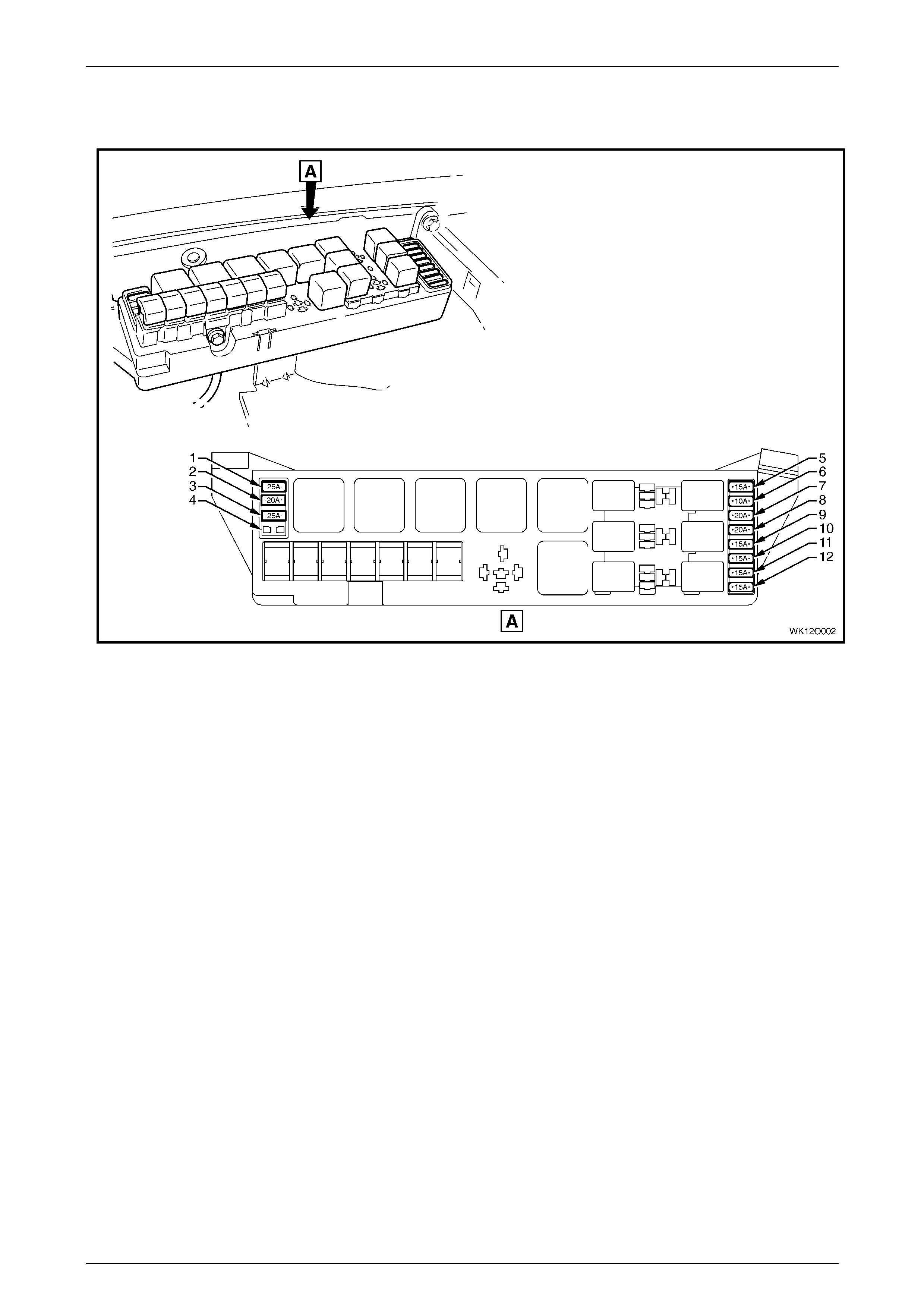
The second group of fuses are located in the engine compartment fuse and relay panel assembly, situated forward of
the right-hand side front suspension strut tower. A label on the inside of the panel cover indicates the circuits protected
by each fuse. Refer to Figure 12O – 3.
Figure 12O – 3
Legend
1 F36 – Throttle Relaxer Module Fuse (25A)
2 F37 – Rear Compartment Power Outlet Fuse (20A)
3 F38 – Level Ride Fuse (25A)
4 F39 – Spare
5 F28 – Fuel Pump Fuse (15A)
6 F29 – Engine, BCM & Telematics Fuse (10A)
7 F30 – Right-hand Headlamp Fuse (20A)
8 F31 – Left-hand Headlamp Fuse (20A)
9 F32 – Automatic Transmission Fuse (15A)
10 F33 – Engine Sensors Fuse (15A)
11 F34 – Fuel Injectors & Ignition Modules Fuse (15A)
12 F35 – Fuel Injectors & Ignition Modules Fuse (15A)
Fuses, Relays and Wi ring Harnesse s Page 12O–8
Page 12O–8
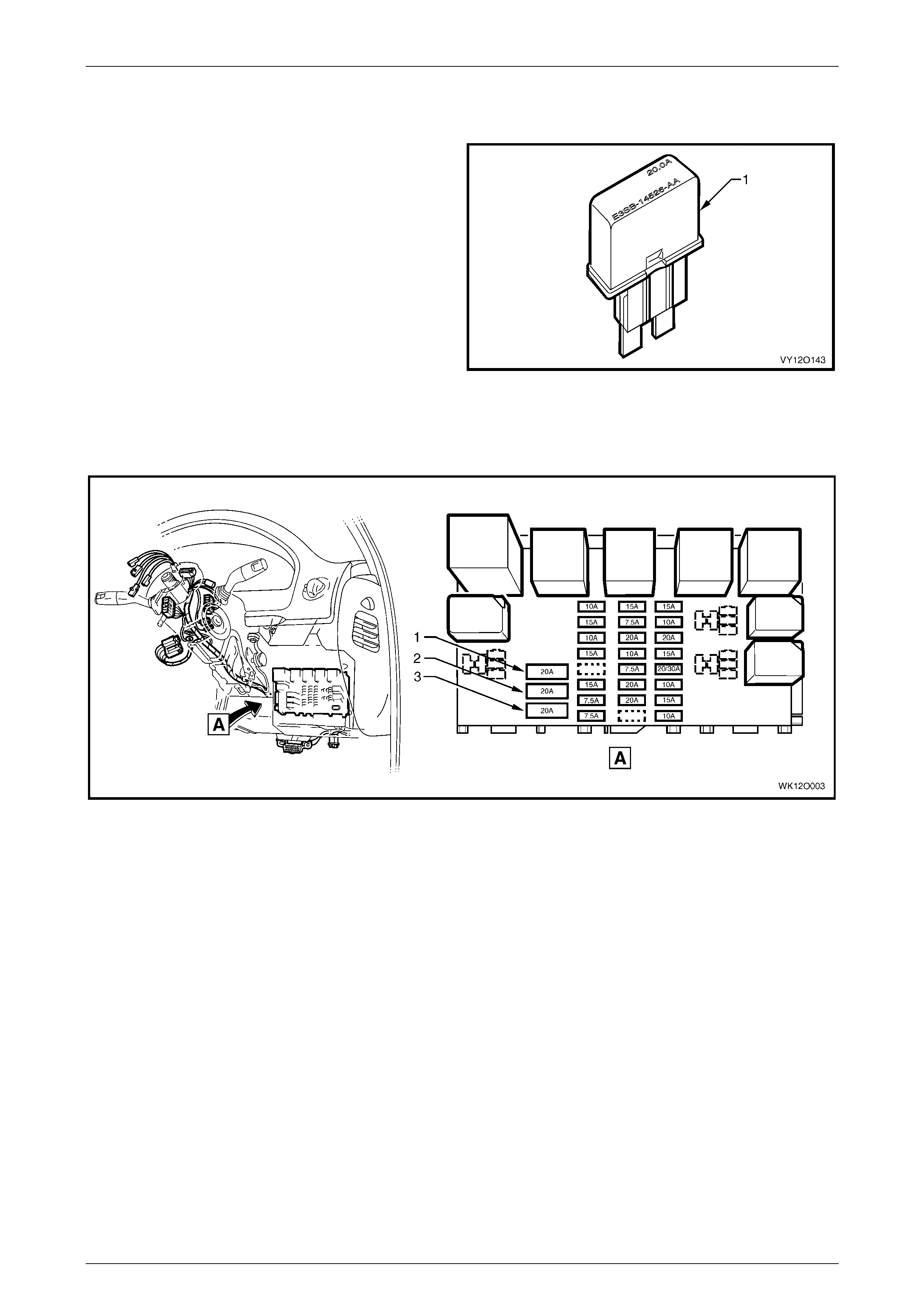
1.2 Circuit Breakers
A circuit breaker is a circuit protection device that will trip
when the circuit current exceeds its rating. The circuit
breaker is activated by heat and will reset after being
allowed to cool. The circ uit bre aker has a limi ted num ber of
tripping cycles before its tripping time will change. The
circuit breaker w ill cont inu e to open and close unti l the
cause of the excess current is corrected.
Figure 12O – 4
In the MY 2004 WK Series all the circuit breakers are located in the passenger compartment fuse and relay panel
assembly and have a 20A current rating. A label on the inside of the panel cover indicates the circuits protected by each
circuit breaker. Refer to Figure 12O – 5.
Figure 12O – 5
Legend
1 F1 – Power Windows Circuit Breaker (20A)
2 F2 – Power Seats Circuit Breaker (20A) 3 F3 – Sunroof Circuit Breaker (20A)
Fuses, Relays and Wi ring Harnesse s Page 12O–9
Page 12O–9
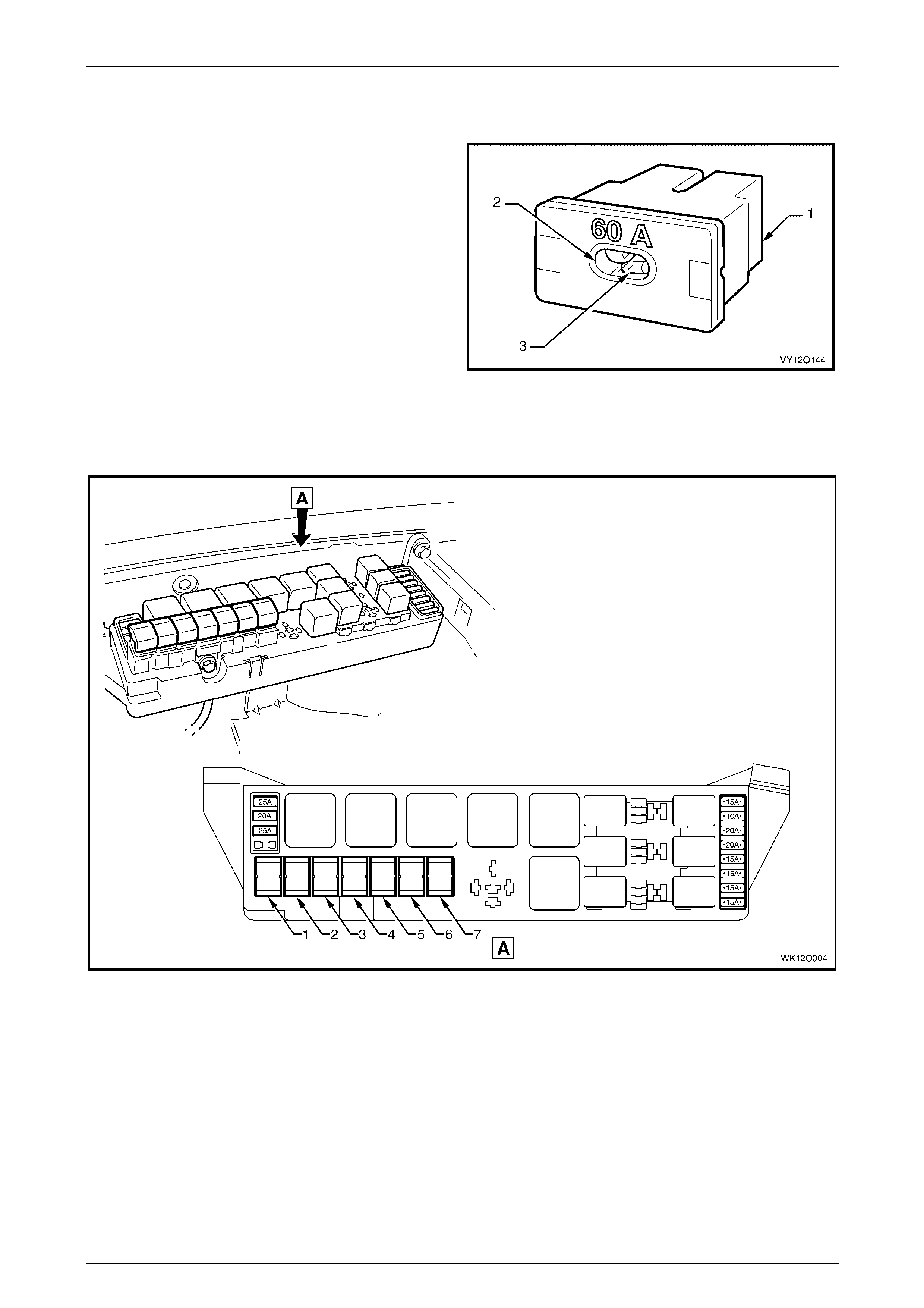
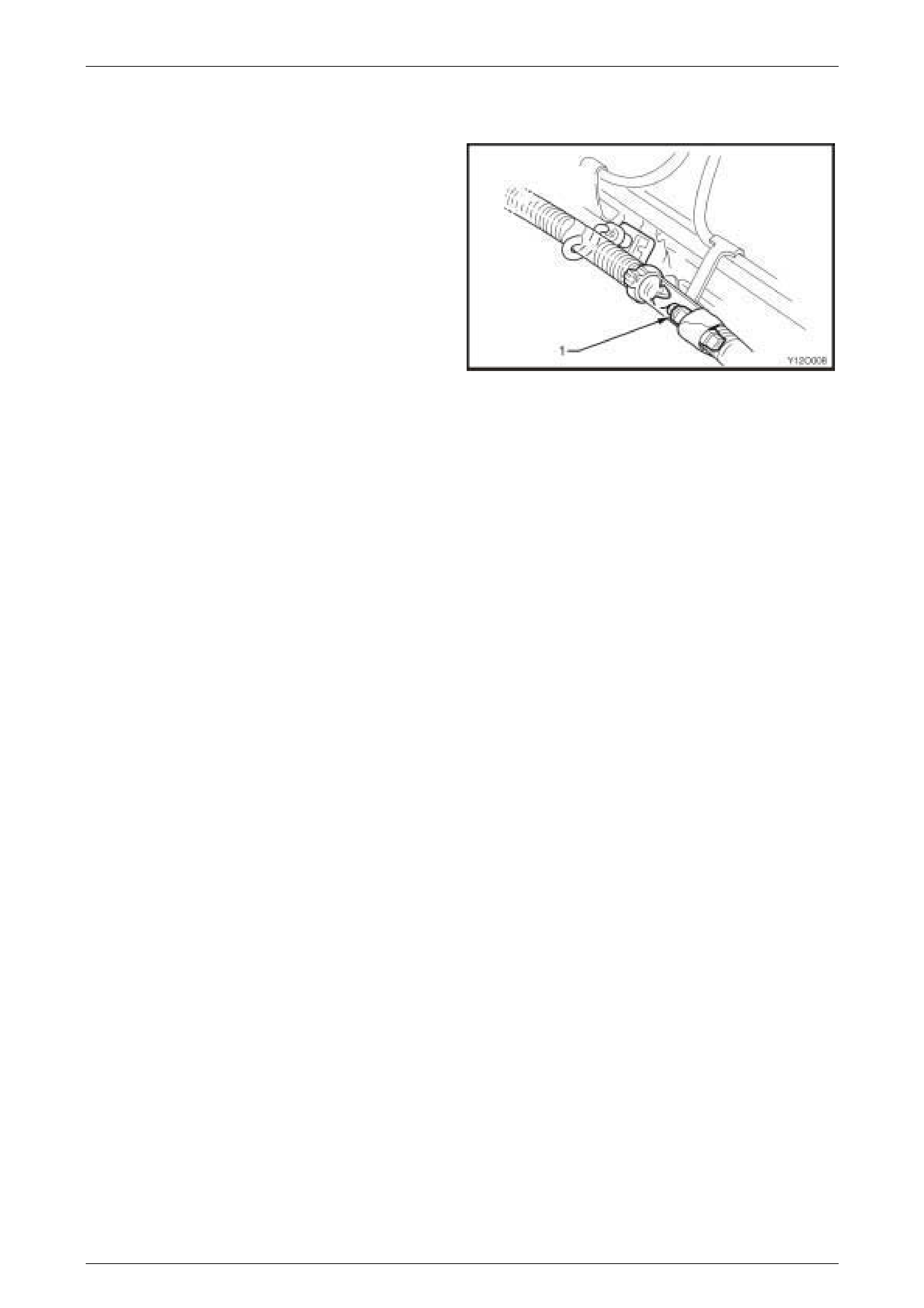
1.3 Fusible Links
The chassis and engine electrical wiring is protected against
short circuit damage by fusible links.
Plug-in type fusible links (1) have an inspection window (2)
that allows a visual check of the condition of the element (3).
Figure 12O – 6
The plug-in type fusible links are located in the engine compartment fuse and relay panel assembly. Refer to
Figure 12O – 7 for the location and usage of the fusible links. A label on the inside of the panel cover indicates the
circuits protected by each fusible link.
Figure 12O – 7
Legend
1 F101 – Engine Cooling Large Fan (30A)
2 F102 – Lighting (60A)
3 F103 – Anti-lock Brakes (60A)
4 F104 – Engine (60A)
5 F105 – Main (60A)
6 F106 – Blower Fan (40A)
7 F107 – Engine Cooling Small Fan (30A)
Fuses, Relays and Wi ring Harnesse s Page 12O–10
Page 12O–10
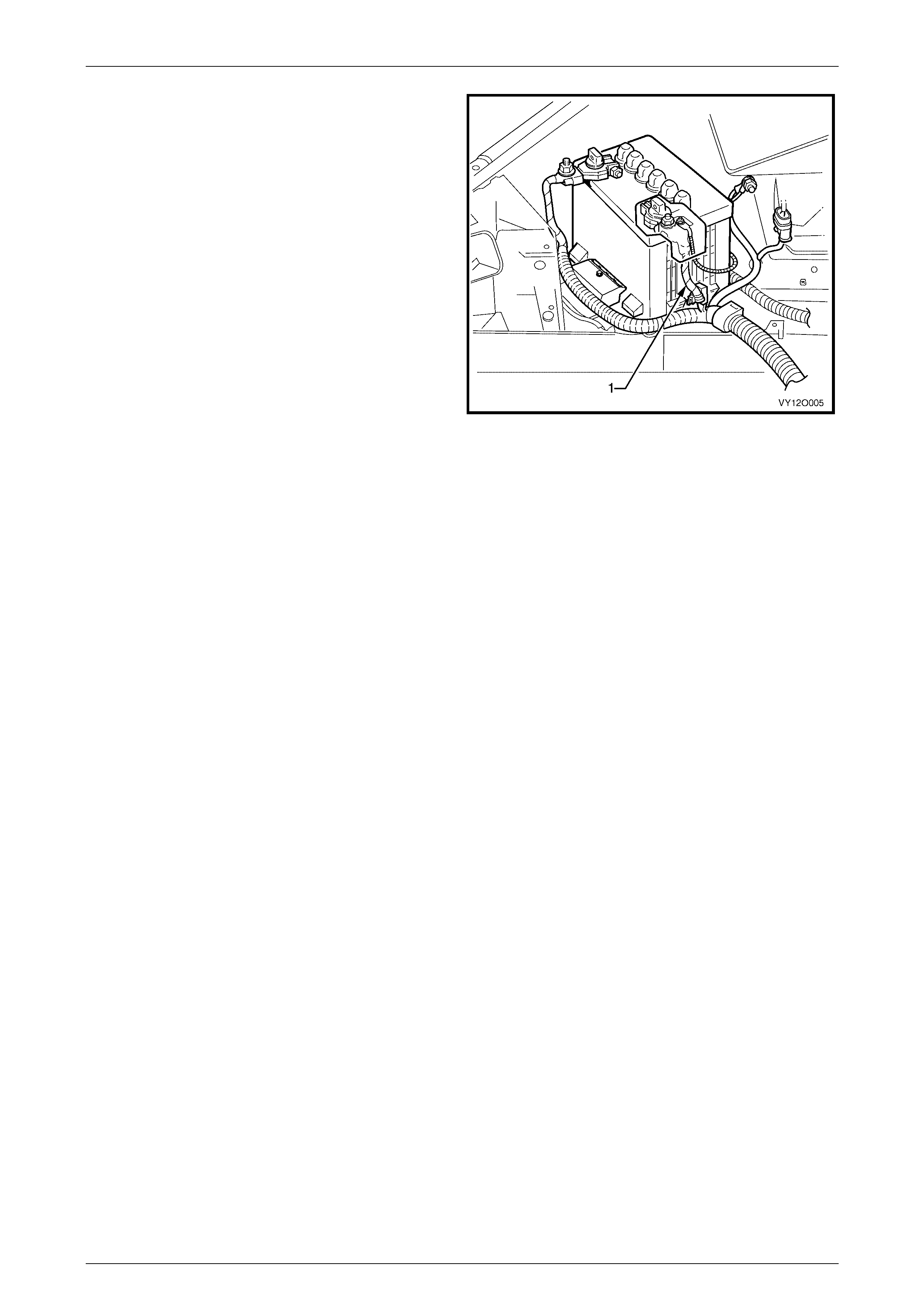
A one-wire type fusible link, consisting of an insulated fuse
wire (1) is attached to the battery harness with cable ties.
This is integrated as part of the battery harness and is
located adjace nt to the battery harness po sitiv e term ina l.
Figure 12O – 8
Fuses, Relays and Wi ring Harnesse s Page 12O–11
Page 12O–11
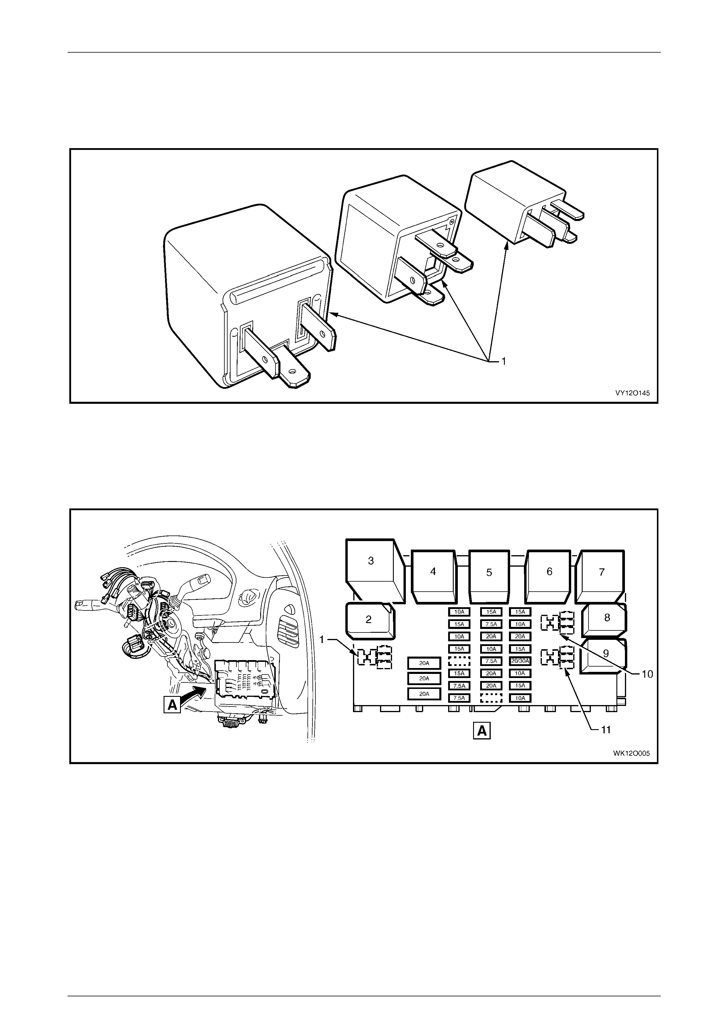
1.4 Relays
There are a vari ety of relay assemblies (1 ) used in the MY 2004 WK Series. The relays are located in the engine
compartment and pa sse nger c ompartment fuse and relay panel assemblies.
Figure 12O – 9
Passenger Compartment Relays
The passenger compartment fuse and relay panel assembly is located behind the instrument panel lower cover. A label
on the inside of the cover indicates the relay location and the circuits protected by each relay. Refer to Figure 12O – 10.
Figure 12O – 10
Legend
1 R17 – Spare
2 R18 – Relay Assembly – Park Lamps (4 Pi n Micro)
3 R19 – Flasher Assembly – Turn Signal (3 Pin)
4 R20 – Relay Assembly – Accessory Control (4 Pin Mini)
5 R21 – Relay Assembly – Ignition Control (4 P i n Mini)
6 R22 – Relay Assembly – Power Windows (4 Pin Mini)
7 R23 – Relay Assembly – Blower Inhibit (4 Pin Mini)
8 R24 – Relay Assembly – Interi or Illumi nation (4 Pin Mini)
9 R25 – Relay Assembly – Defog (4 Pin Micro)
10 R26 – Spare
11 R27 – Spare
Fuses, Relays and Wi ring Harnesse s Page 12O–12
Page 12O–12
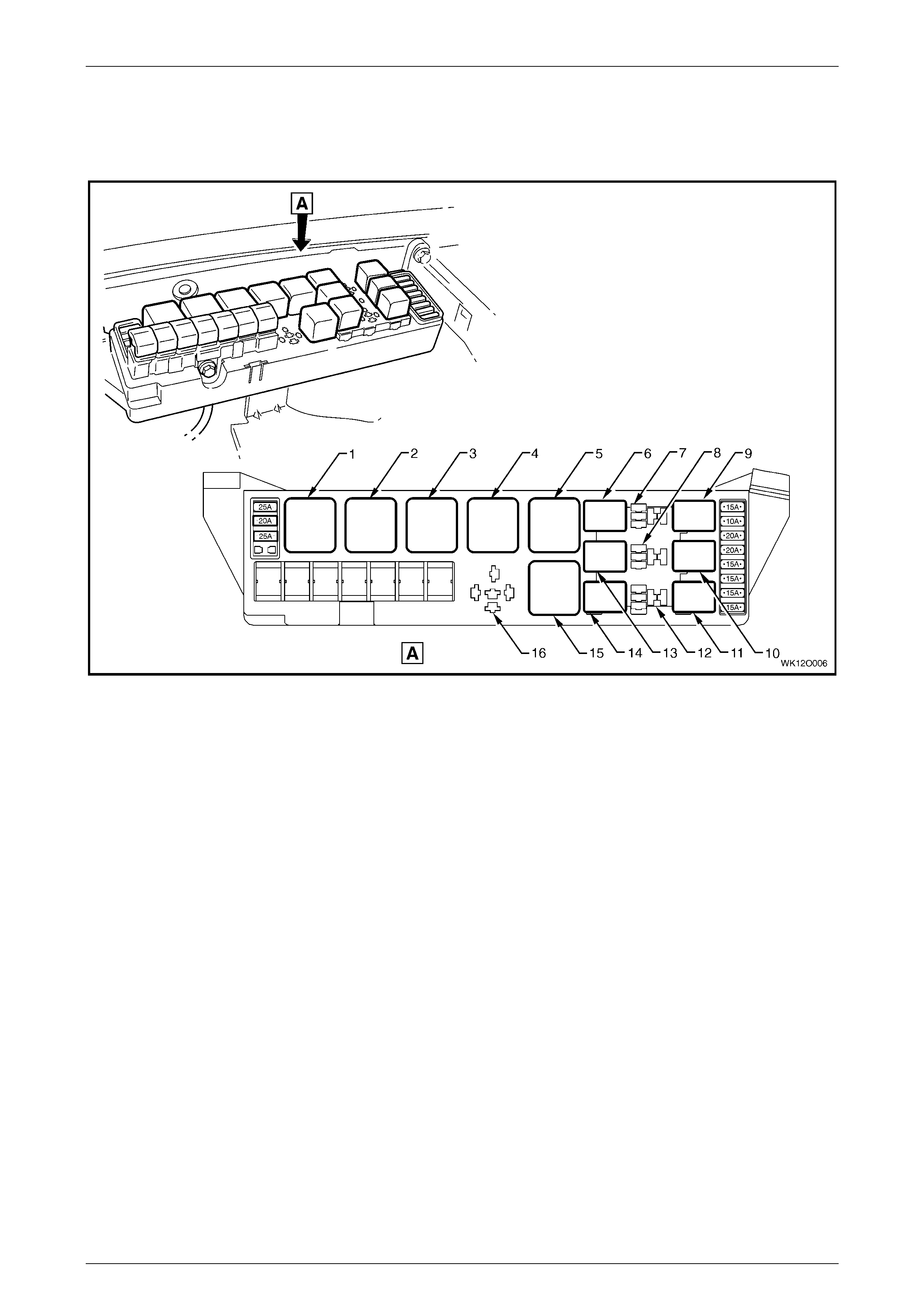
Engine Compartment Relays
The engine compartment fuse and relay panel assembly is located forward of the right-hand side front suspension strut
tower. A label on the inside of the cover lists the relay location and the circuits protected by each relay. Refer to
Figure 12O – 11.
Figure 12O – 11
Legend
1 R1 – Start Relay (4 Pin)
2 R2 – Blower Relay (4 Pin)
3 R3 – Headlamp Hi-beam Relay (4 Pin)
4 R4 – E.F.I. Relay (4 Pin)
5 R5 – Engine Cooling Fan Relay 2 – High Speed (4 Pin)
6 R8 – Horn Relay (4 Pin Micro)
7 R9 – Spare
8 R12 – Spare
9 R10 – Fog Lamp Relay (4 Pin Micro)
10 R13 – Level Ride Relay (4 Pin Micro)
11 R16 – Fuel Pump Relay (4 Pin Micro)
12 R15 – Spare
13 R11 – A/C Relay (4 Pin Micro)
14 R14 – Headlamp Lo-beam Relay (4 Pin Micro)
15 R7 – Engine Cooling Fan Relay 1 – Lo Speed (5 Pin)
16 R6 – Spare
Fuses, Relays and Wi ring Harnesse s Page 12O–13
Page 12O–13
1.5 Diodes
All vehicles with air conditioning have an air conditioning
compressor clutch suppression diode (1) fitted to the engine
harness.
For location of the air-conditioning compressor clutch
feedback diode, refer to the following figures:
a. 3.6 Powertrain Harness – 3, item 6.
b. 3.10 Powertrain Harness – 7, item 2.
c. 3.13 Powertrain Harness – 10, item 10.
Figure 12O – 12
Fuses, Relays and Wi ring Harnesse s Page 12O–14
Page 12O–14
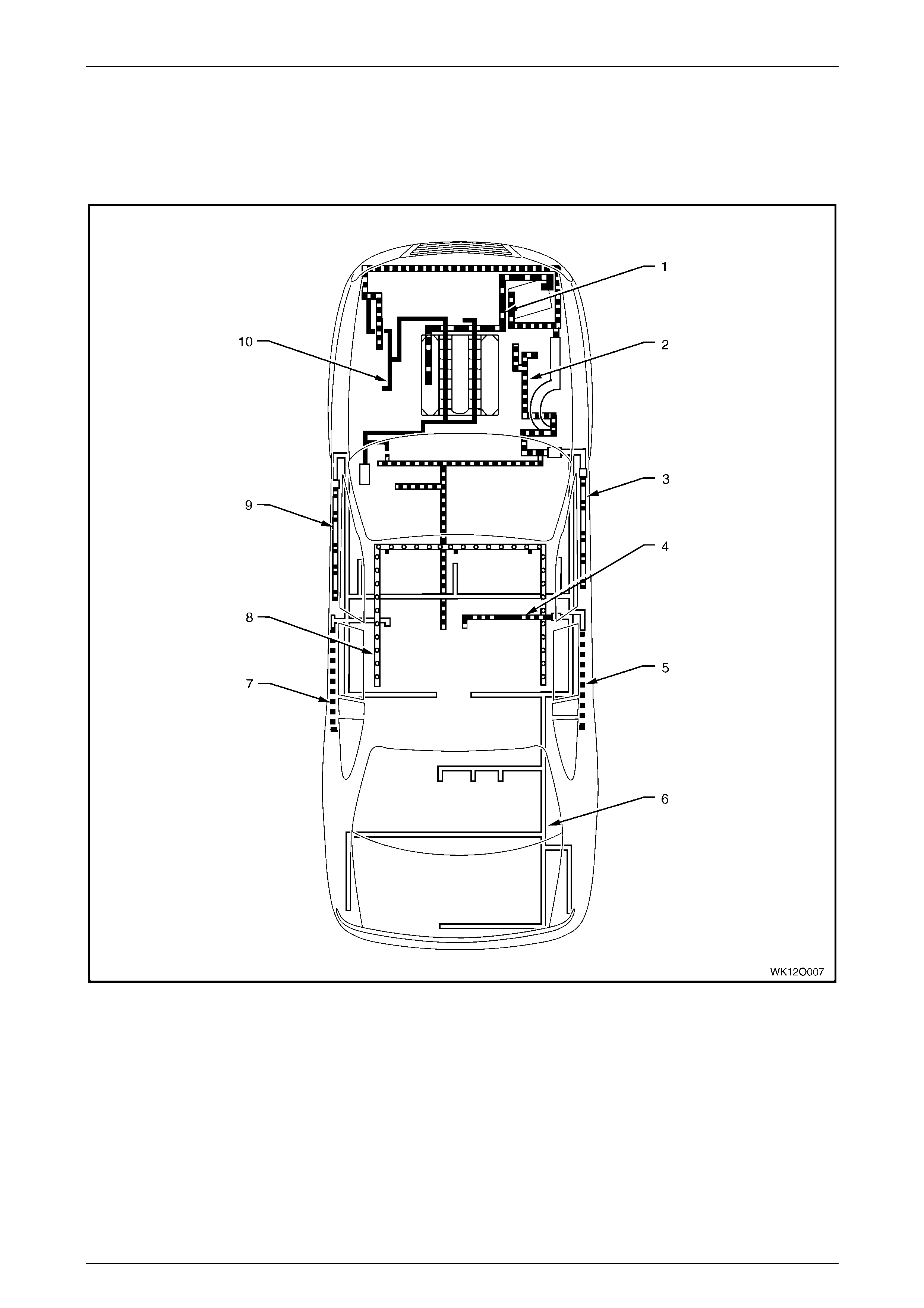
1.6 Wiring Harnesses
Refer to Figure 12O – 13 for the location of the wiring harnesses used in the MY 2004 WK series. For a detailed layout
of the various wiring harnesses and connectors refer to 3 Wiring Installation Diagrams – Right-hand Drive and
4 Wiring Installation Diagrams – Left-hand Drive.
Figure 12O – 13
Legend
1 Battery Wiring Harness
2 Main Wiring Harness
3 Right-hand Front Door Wi ri ng Harness
4 Roof Lamp Harness
5 Right-hand Rear Door W i ri ng Harness
6 Body Wiring Harness
7 Left-hand Rear Door Wiri ng Harness
8 Visor Lamp Harness
9 Left-hand Front Door Wiring Harness
10 Powertrain Harness

Fuses, Relays and Wi ring Harnesse s Page 12O–15
Page 12O–15
1.7 Wiring Harness Connectors
The majority of the wiring harness connectors used on MY 2004 WK series are of an interlocking design.
The male and female connector bodies, when pushed together, cannot be pulled apart due to the presence of a locking
tang on the connector body. Some connectors have anti-backout combs fitted for increased connector terminal security.
Fuses, Relays and Wi ring Harnesse s Page 12O–16
Page 12O–16
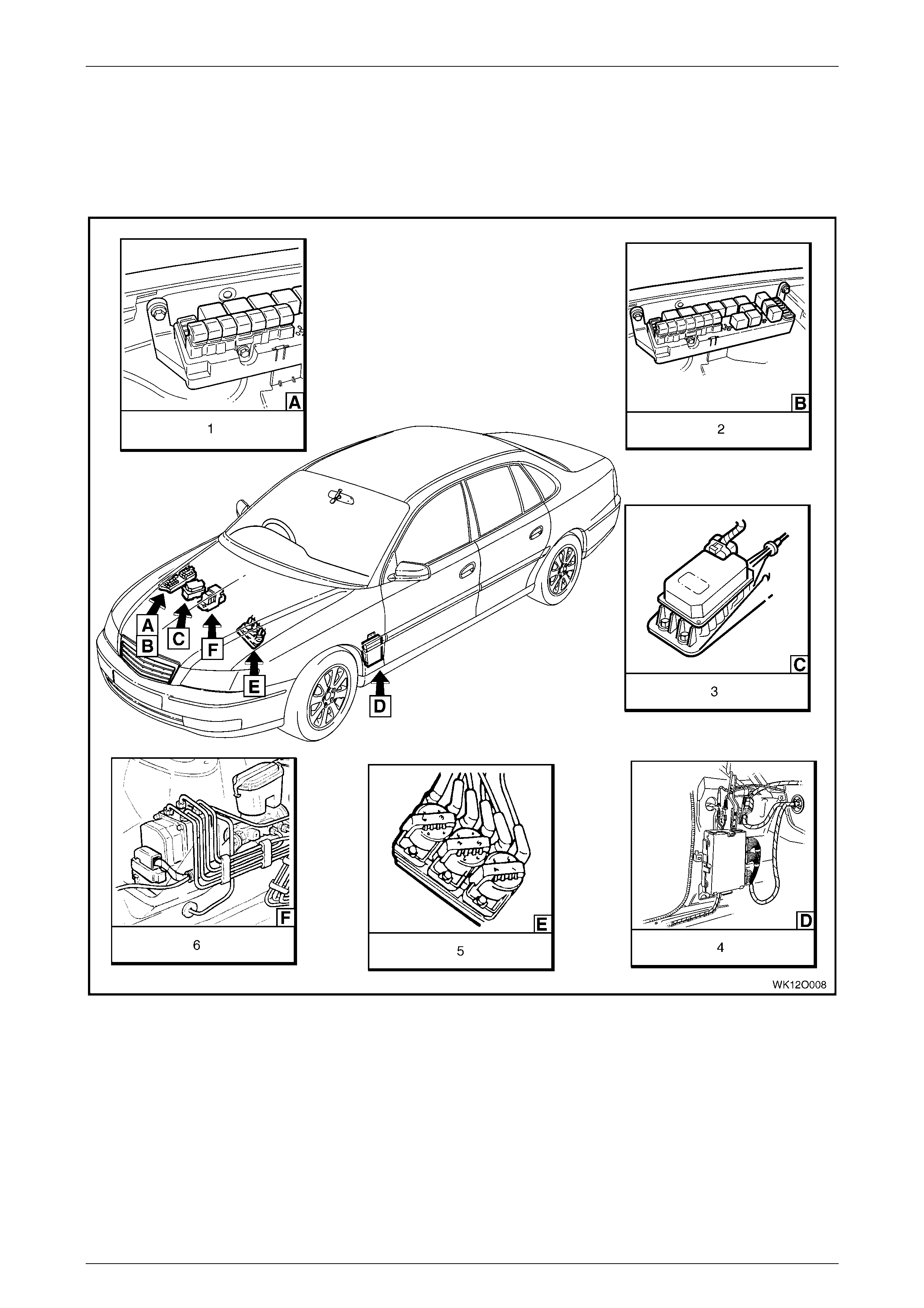
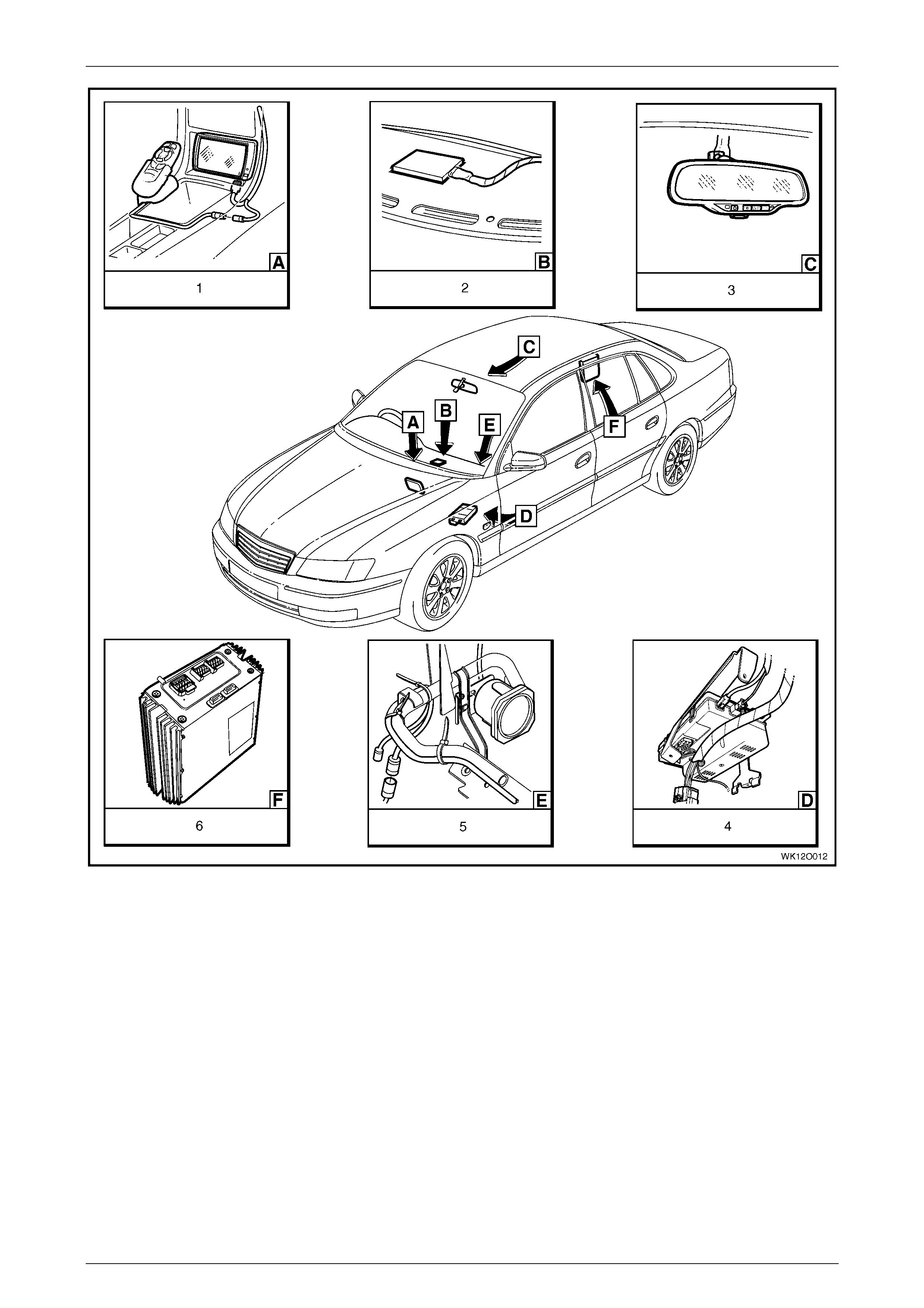
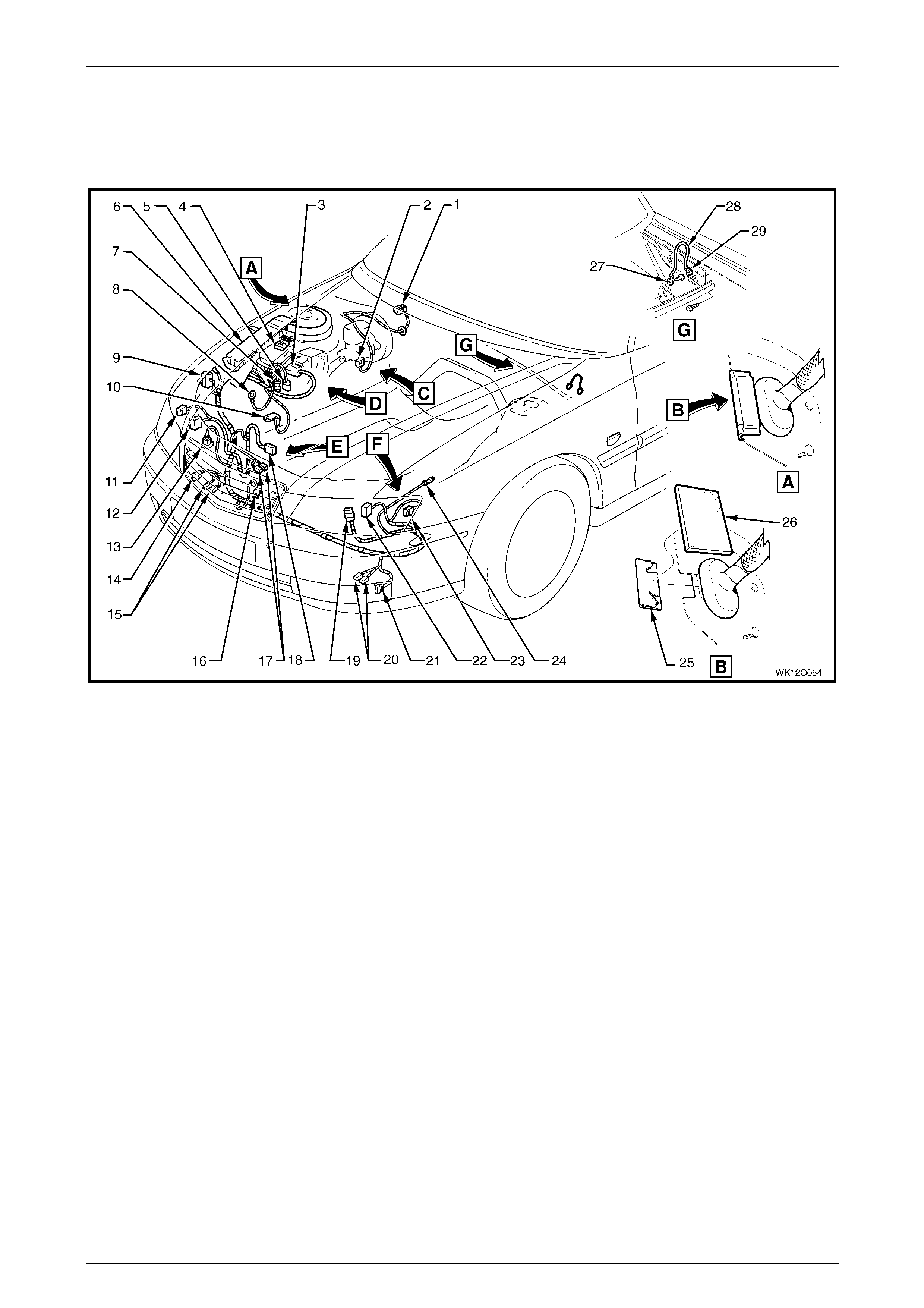
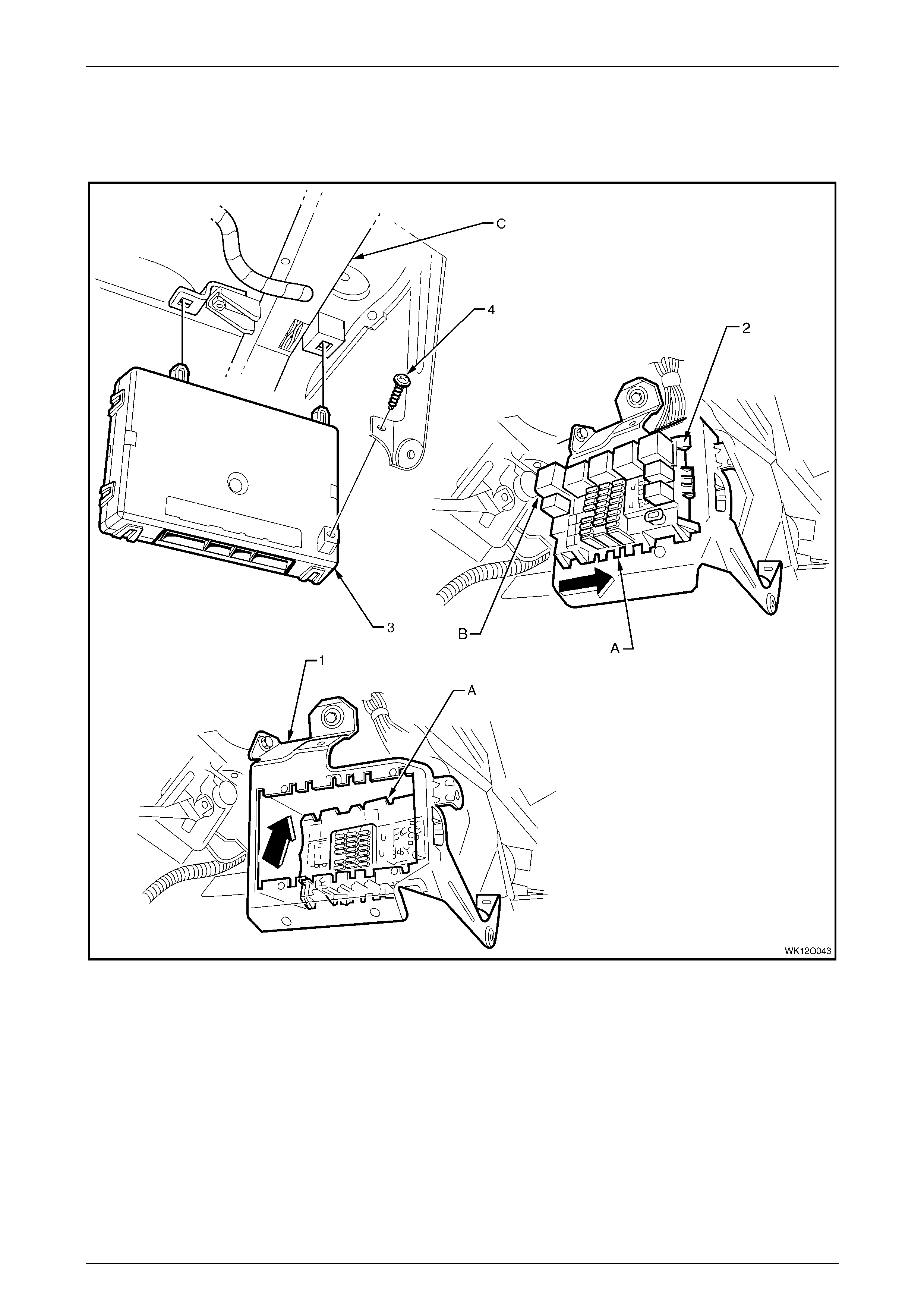
1.8 Electronic Control Device Locations
The following figures illustrate the location of the various electronic control devices fitted to MY 2004 WK series.
Ensure that the precautionary and special handling instructions are followed (where applicable) for each electronic
control device as des cribed in the correspondin g sections.
Figure 12O – 14
Legend
1 Fusible Links
2 Relays & Fuses – Engine compartment
3 Cruise Control Module
4 Powertrain Control Module (P CM) – V6 Engine
5 Direct Ignition System (DIS) Module – V6 Engine
6 ABS Hydraulic Modulator

Fuses, Relays and Wi ring Harnesse s Page 12O–17
Page 12O–17
Figure 12O – 15
Legend
1 Relays & Fuses – Instrument P anel
2 Body Control Module
3 Powertrain Control Module – Gen III V8 Engine
4 Steering Wheel Radio & CD Player Control s
5 Powertrain Interface Module (PIM) – GEN III V8 Engine
6 Climate Control Module
7 Ambient Light Sensor
Fuses, Relays and Wi ring Harnesse s Page 12O–18
Page 12O–18
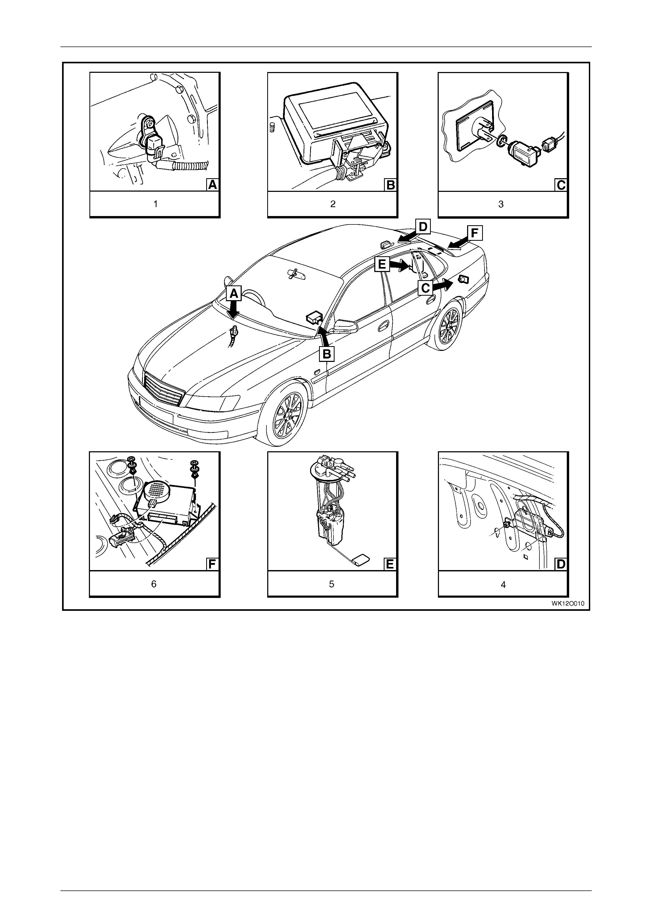
Figure 12O – 16
Legend
1 Vehicle Speed Sensor – Automatic Transmission
2 Sensing & Diagnostic Module – Occ upant
Protection System
3 Rear Object Sensor Assembl y
4 Fuel Pump Control Module – V6 Supercharged Engine
5 Modular Fuel Pump & Sender Assembly
6 Rear Object Sensor Control Module

Fuses, Relays and Wi ring Harnesse s Page 12O–19
Page 12O–19
Figure 12O – 17
Legend
1 Rear Speaker Amplifier
2 Radio Assembly
3 Rear Speaker (2 Places)
4 Rear Door Speaker Assembl y (2 Places )
5 Anti-theft Horn
6 Front Door Speaker Assembly (2 Places)
7 DVD Player Assembly
Fuses, Relays and Wi ring Harnesse s Page 12O–20
Page 12O–20
Figure 12O – 18
Legend
1 Navigation S ystem Assembly
2 Telematics Antenna
3 Rear View Mirror Assembly with Telematics
4 Telematics Cont rol Module
5 Navigation S ystem Speaker
6 Radio Speaker Amplifier

Fuses, Relays and Wi ring Harnesse s Page 12O–21
Page 12O–21
2 Service Operations
All the service operations associated with fuses, relays and wiring harnesses for MY 2004 WK Series carry over from
those described in Section 12O Fuses, Relays and Harnesses in the MY 2003 VY and V2 Series Service Information.
Fuses, Relays and Wi ring Harnesse s Page 12O–22
Page 12O–22
3 Wiring Installation Diagrams –
Right-hand Dri ve
The following figures illustrate the vehicle wiring installation diagrams for MY 2004 WK right-hand drive Sedan.
Some of the diagrams in this Se ction are applicable to both right-hand and left-hand drive vehicles. Those diagrams
applicable to right-h and driv e only vehic le s are indicated as suc h.
NOTE: Some of the following wiring installation diagrams illustrate the upper level harnesses which incorporate all
necessary wiring harness connectors for all production options. Depending on equipment level and vehicle model, some
of the connectors may be taped back to the harness when a particular option is not fitted, or the particular level of
harness fitted to the vehicle may not incorporate some of the connectors illustrated.
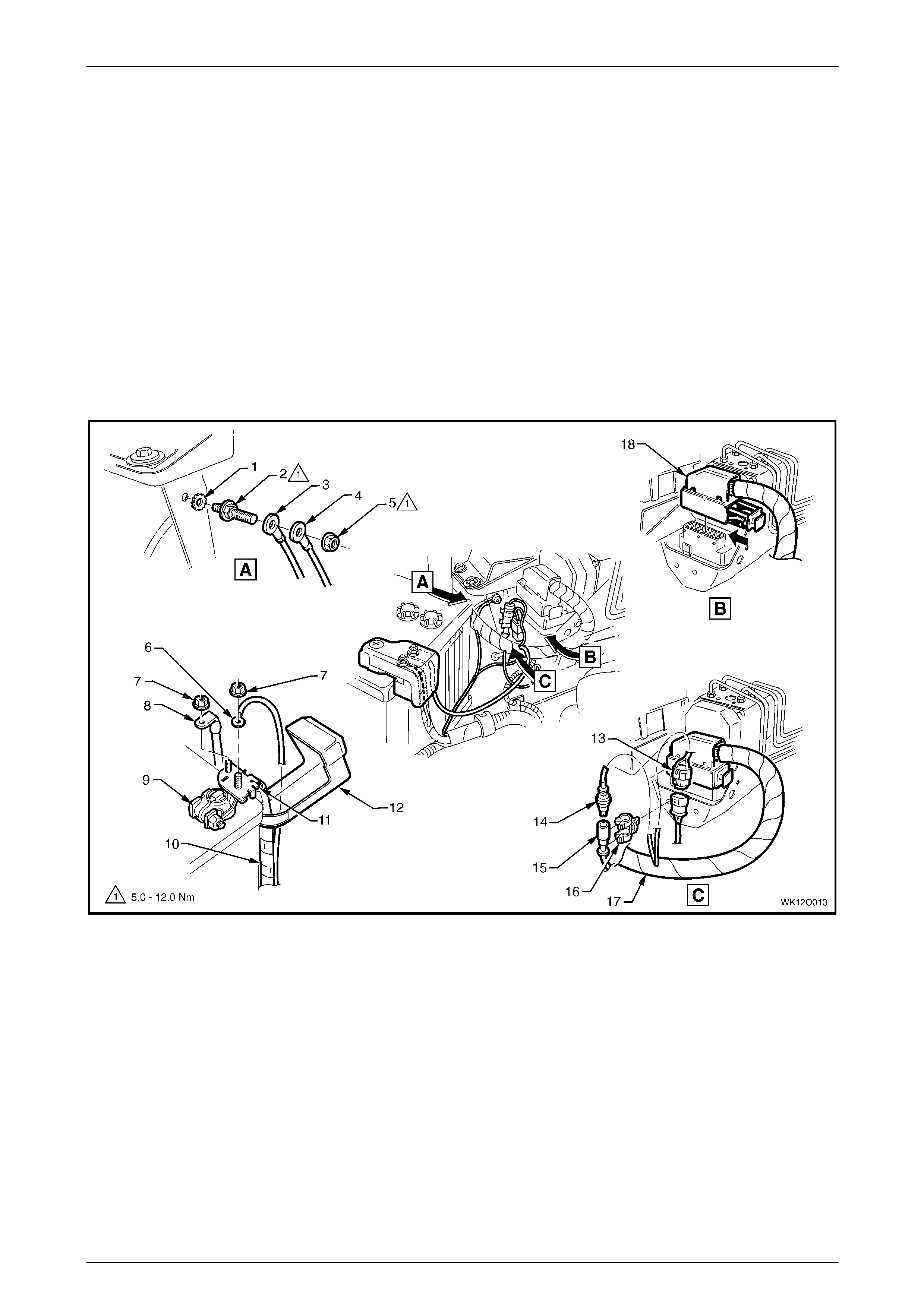
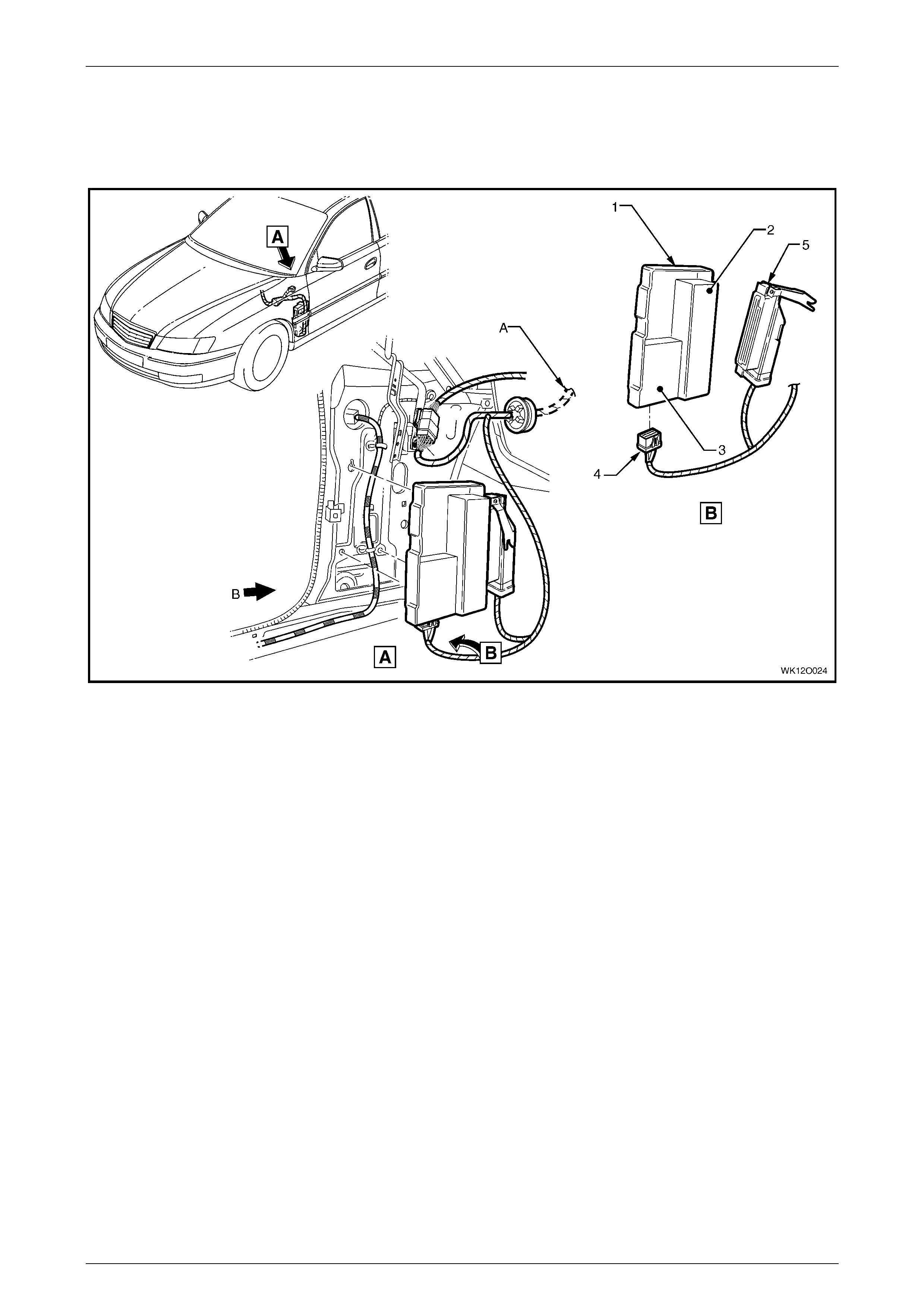
3.1 Battery Wiring Harness – 1
Battery and ABS
Figure 12O – 19
Legend
1 Washer
2 Stud
3 Body Earth Terminal
4 Battery Earth Terminal
5 Nut
6 Voltage Sense Terminal (X86 – C)
7 Nut
8 Fuse Panel Supply Terminal (X86 – A)
9 Battery Harness Positive Terminal (G1 – X1)
10 Battery Harness to Starter Motor and Generator
11 Battery Positive Post Assembly (X86 – B)
12 Positive Battery Terminal Cover
13 Main Wiring Harness to Battery Wiring Harness Connec tor
(X106)
14 ABS to Main Wiring Harness Connec t or (B52)
15 ABS to Front Left Wheel Connector (B52)
16 ABS Connector Retainer
17 Main Wiring Harness
18 Electronic Braking & Traction Control Connector (A37)
Fuses, Relays and Wi ring Harnesse s Page 12O–23
Page 12O–23
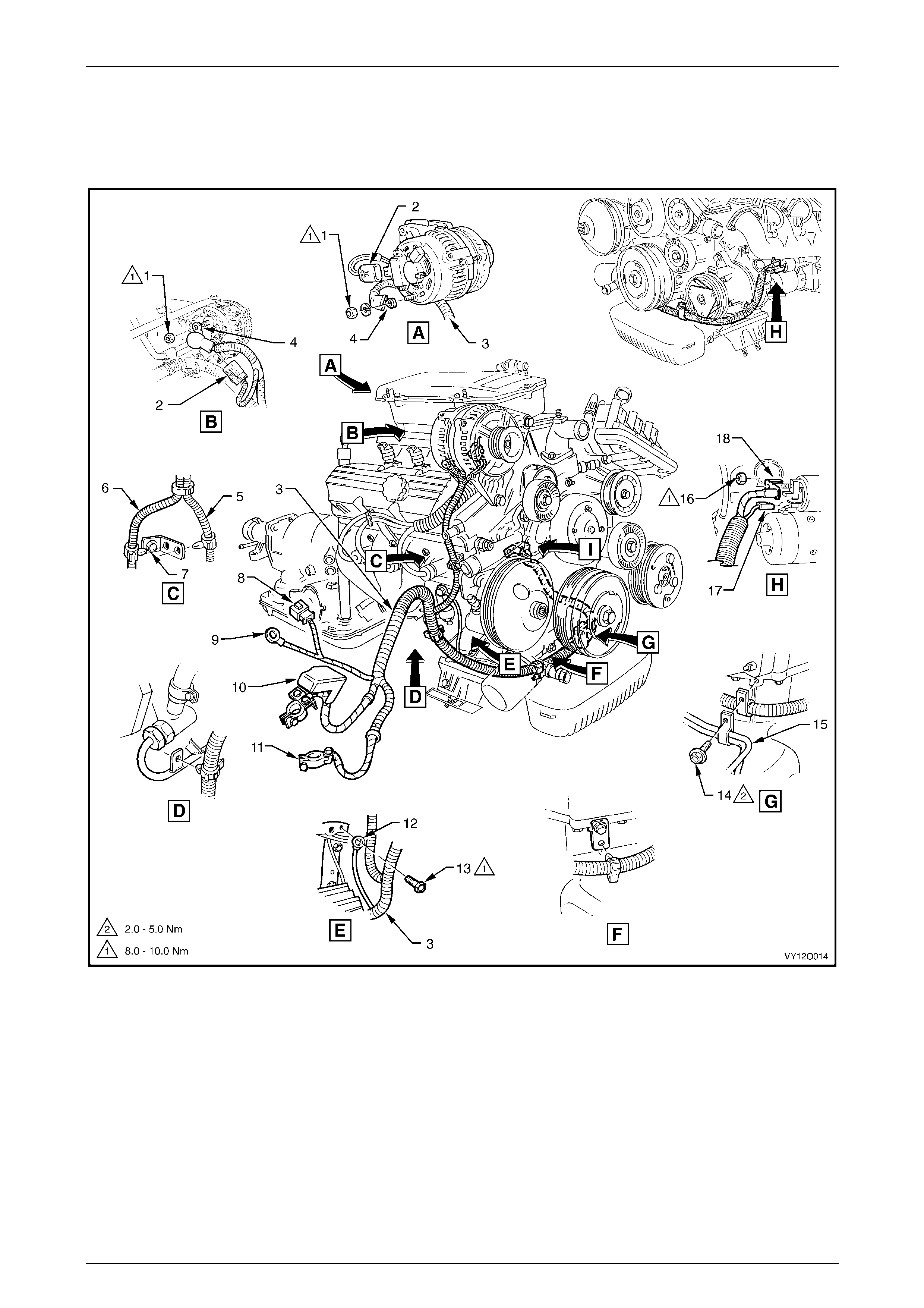
3.2 Battery Wiring Harness – 2
V6 Engine
Figure 12O – 20

Fuses, Relays and Wi ring Harnesse s Page 12O–24
Page 12O–24
Legend
1 Nut
2 Generator Connect or (G8 – X2)
3 Battery Wiring Harness
4 Generator Terminal (G8 – X1)
5 Clip (2 places)
6 Powertrain Harness
7 Bracket – Battery W i ri ng Harness to Engine
8 Batte ry Wi ring Harness to Main Wiring Harness Connector
(X106)
9 A.B.S. Bracket Terminal (X119 – G4 – GP3)
10 Batt ery Connector – Positive (G1 – X1)
11 Battery Connector – Negative (G1 – GP1 – X2)
12 Engine Ground Terminal (X119 – GP4)
13 Engine Block Earth Bolt
14 Bolt
15 Oil Cooler Pipes
16 Nut
17 Starter Motor Terminal Connector (M15 – X1)
18 Starter Motor Terminal (M15 – X2)
Fuses, Relays and Wi ring Harnesse s Page 12O–25
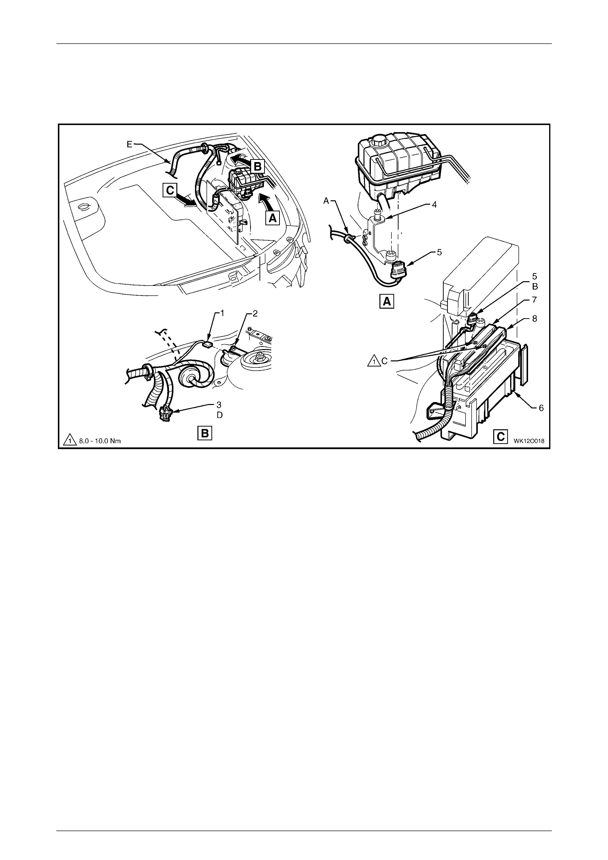
Page 12O–25
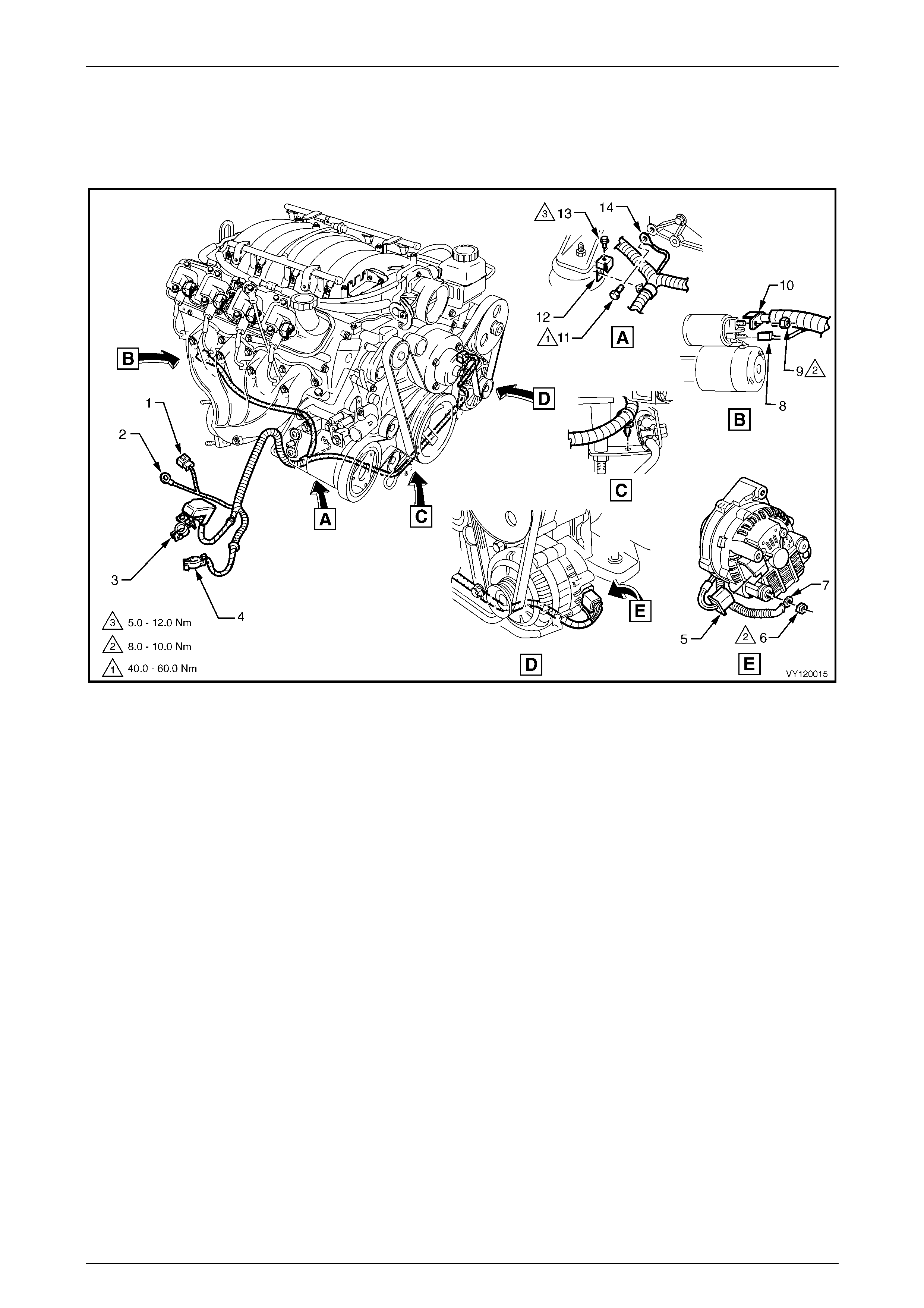
3.3 Battery Wiring Harness – 3
Gen III V8 Engine
Figure 12O – 21
Legend
1 Batte ry Wi ring Harness to Main Wiring Harness Connector
(X106)
2 A.B.S. Bracket Terminal (X119 – G4 – GP3)
3 Batt ery Connector – Positive (G1 – X1)
4 Battery Connector – Negative (G1 – GP1 – X2)
5 Generator Connect or (G8 – X2)
6 Battery Wi ring Harness to Generator B+ Terminal Nut
7 Generator Terminal (G8 – X1)
8 Starter Motor Terminal Connector (M15 – X1)
9 Battery Wiring Harness to Starter Motor Solenoid Attaching
Nut
10 Starter Motor Terminal (M15 – X2)
11 Battery Wiring Harness Earth to Block Screw
12 Battery Wiring Harness Bracket
13 Battery Wiring Harness Bracket to Engine Mounting Screw
14 Engine Ground Terminal (X119 – GP4)
Fuses, Relays and Wi ring Harnesse s Page 12O–26
Page 12O–26
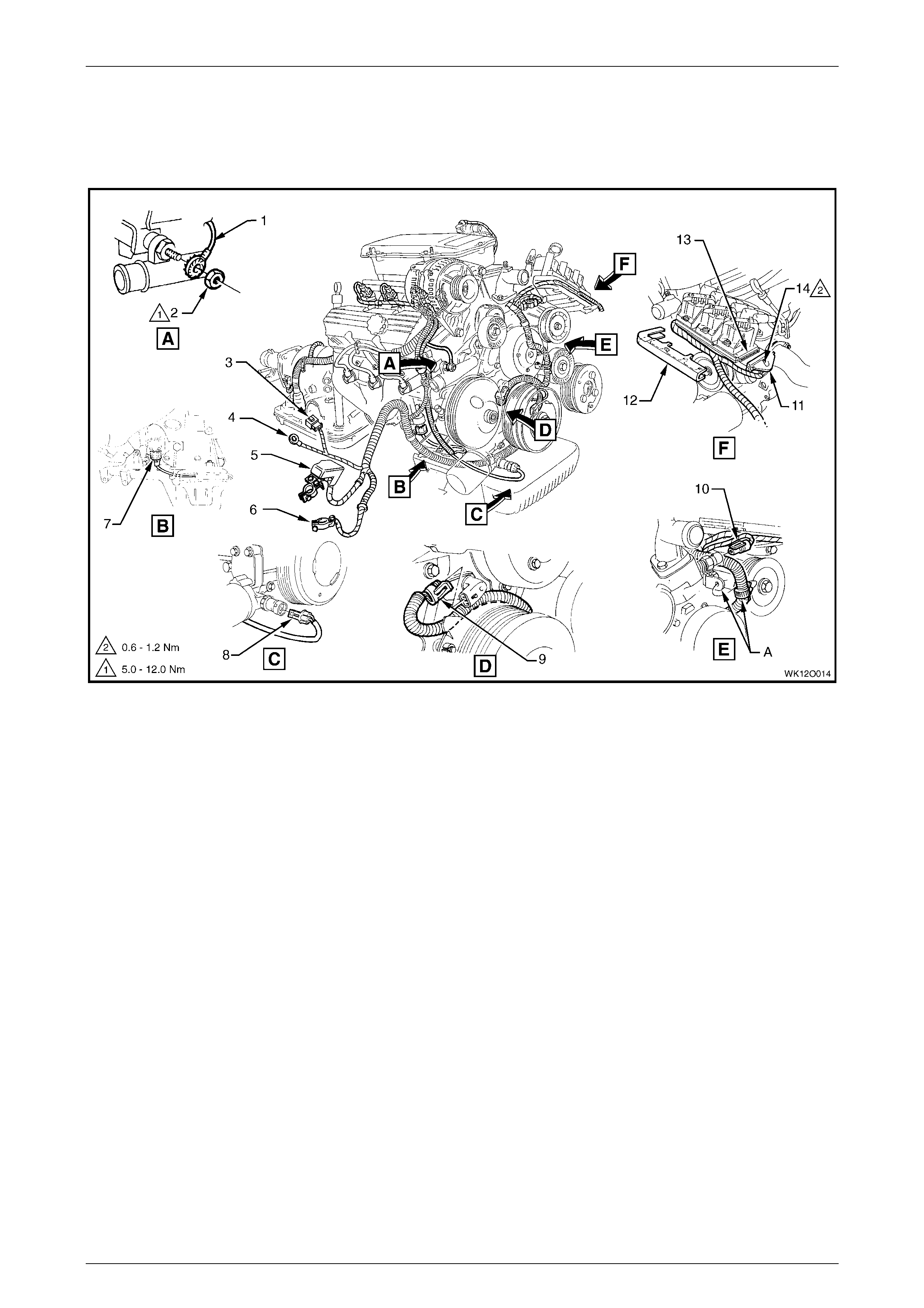
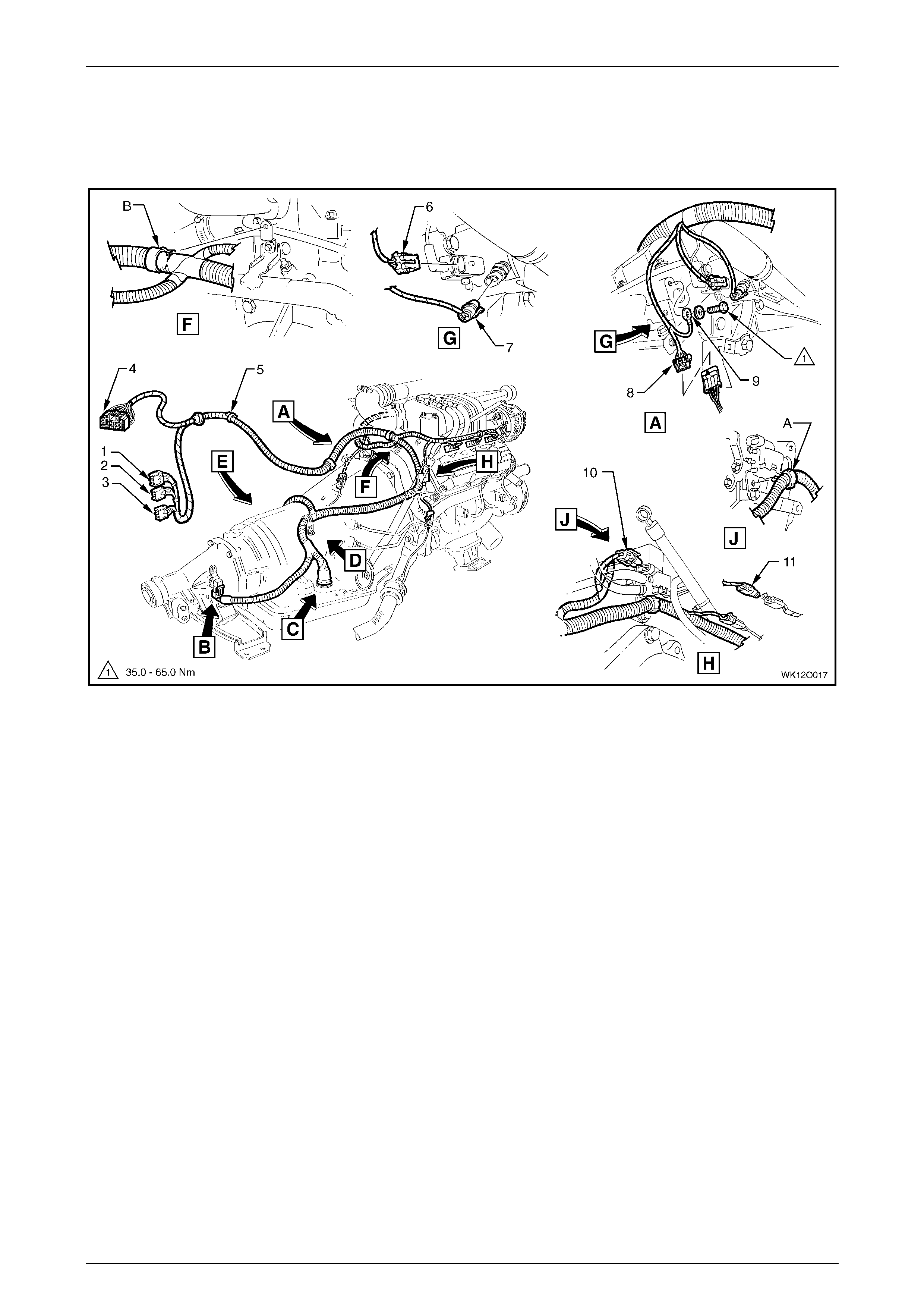
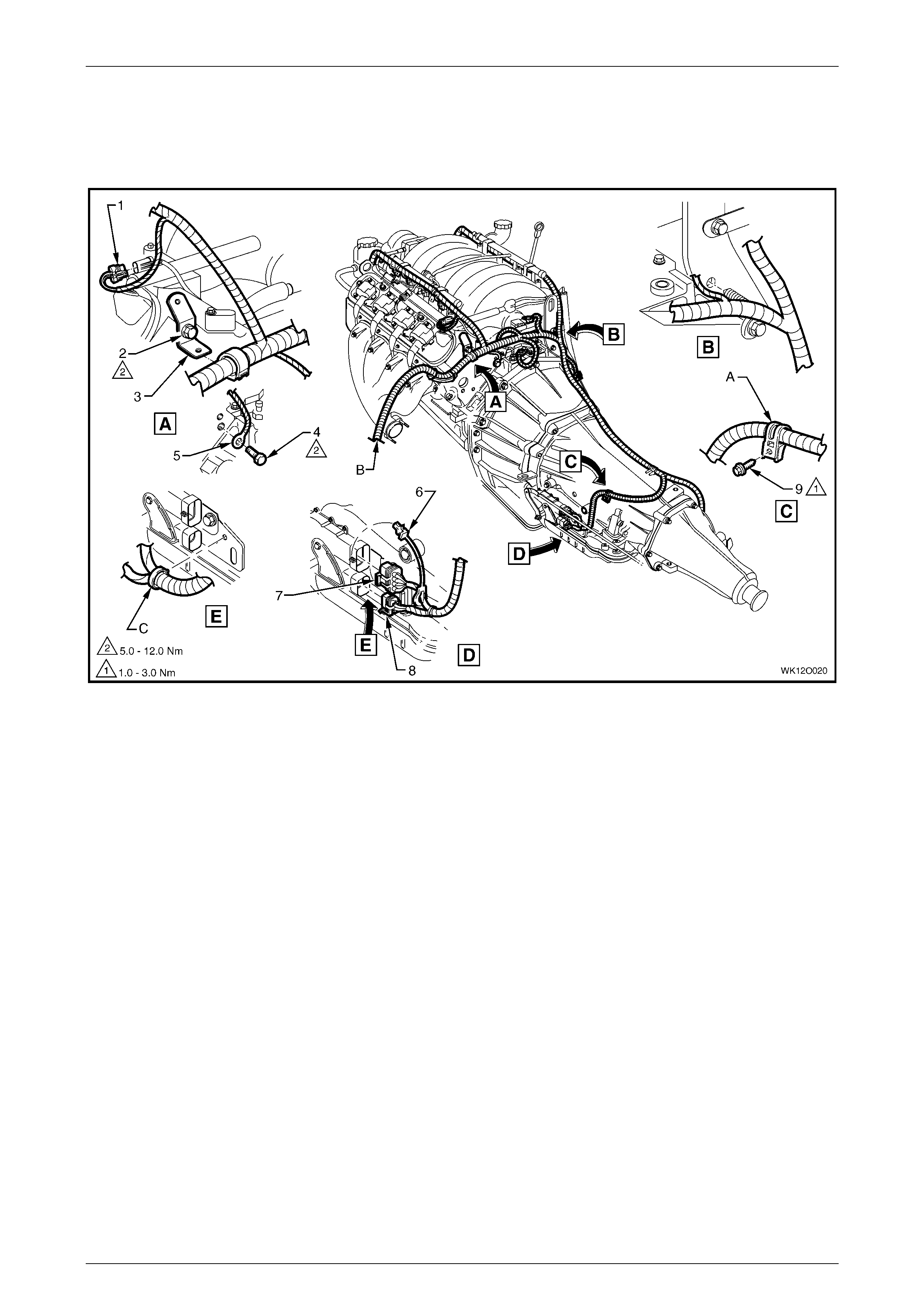
3.4 Powertrain Harness – 1
V6 Engine and V6 Supercharged Engine
Figure 12O – 22
Legend
1 Theft Deterrent Horn Connect or (B9)
2 Anti-theft horn
3 Powertrain Harness Cl i p (2 Places)
4 Dash Upper Panel Assembly
5 Cruise Control Cabl e
6 Throttle Cable
7 Powertrain Harness
8 Main Wiring Harness
9 Powertrain Harness Attaching Bracket
10 Bolt
A For continuation, refer to 3.19 Powertrain Harness – 16.
B View shows V6 supercharged engine.
Fuses, Relays and Wi ring Harnesse s Page 12O–27
Page 12O–27
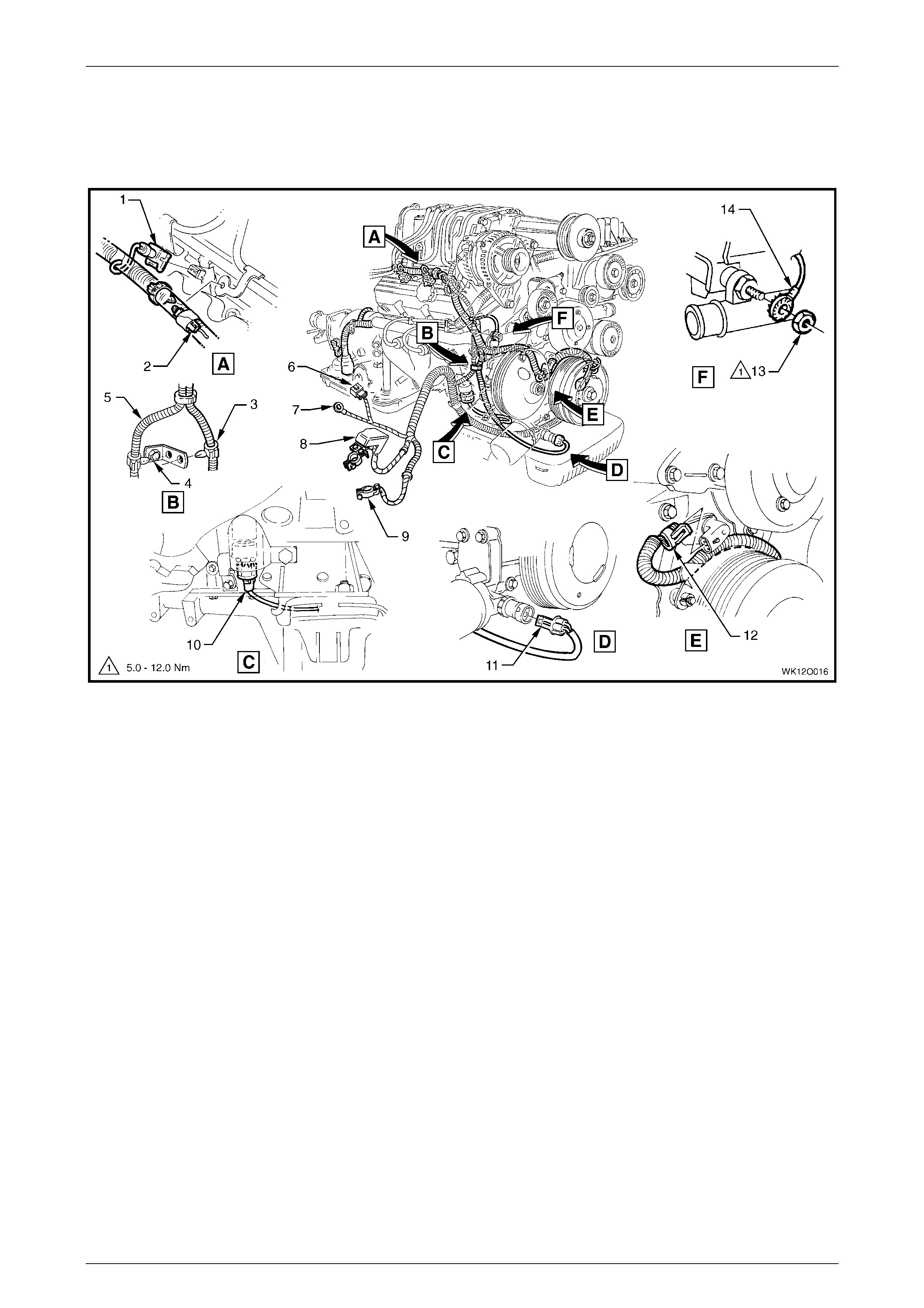
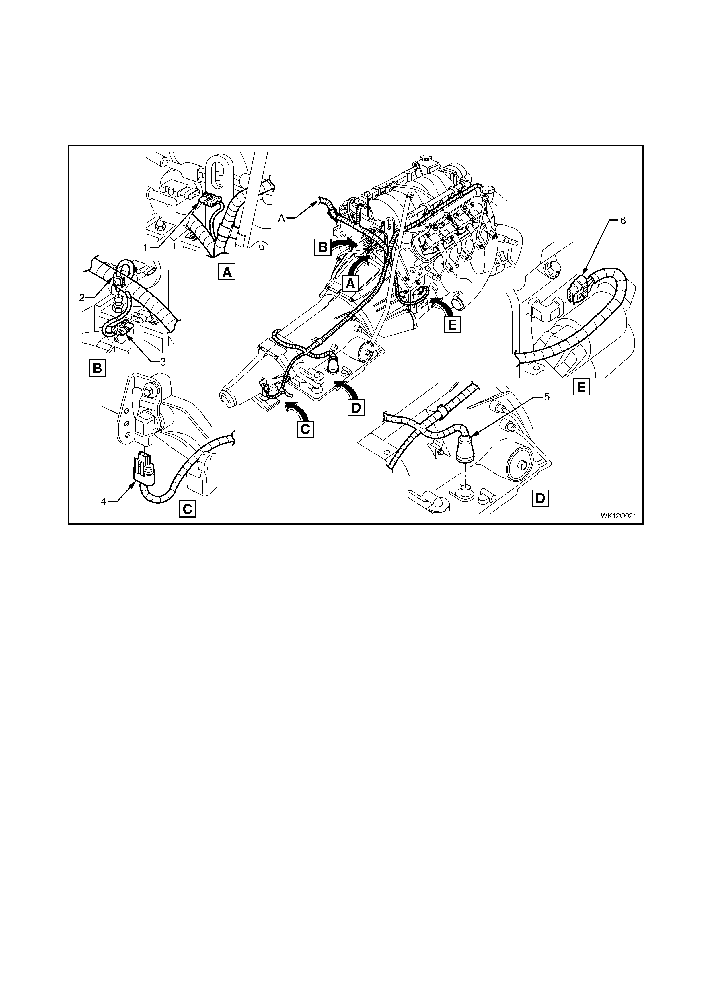
3.5 Powertrain Harness – 2
V6 Normally Aspirated Engine
Figure 12O – 23
Legend
1 Engine Ground Terminal (X119 – GP4)
2 Nut
3 Batte ry Wi ring Harness to Main Wiring Harness Connector
(X106)
4 A.B.S. Brack et Terminal Connect or (X119 – G4 – GP3)
5 Batt ery Connector – Positive (G1 – X1)
6 Battery Connector – Negative (G1 – GP1 – X2)
7 Knock Sensor Connect or (B65– V6)
8 Engine Oil Pressure Indicat or Switc h Connector (S87)
9 Camshaft Posit i on Sens or Connector (B 28 – V6)
10 Engine Coolant Temperat ure Sensor Connector (B 39)
11 Electroni c I gnit i on Cont rol Module Connector (A 40 – V6)
12 Powertrain Harness Retainer
13 Electroni c I gnition Control Module
14 Electroni c I gnition Control Module Connector Retaini ng Bolt
A Powertrain harness secured to bracket as shown.
Fuses, Relays and Wi ring Harnesse s Page 12O–28
Page 12O–28
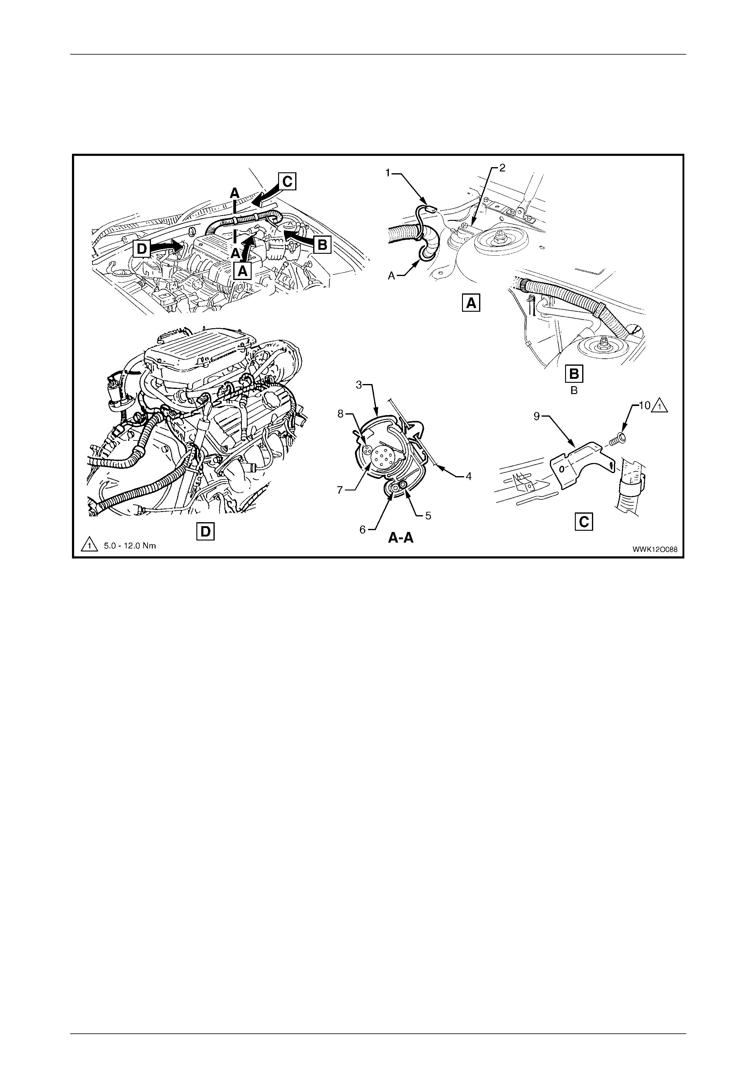
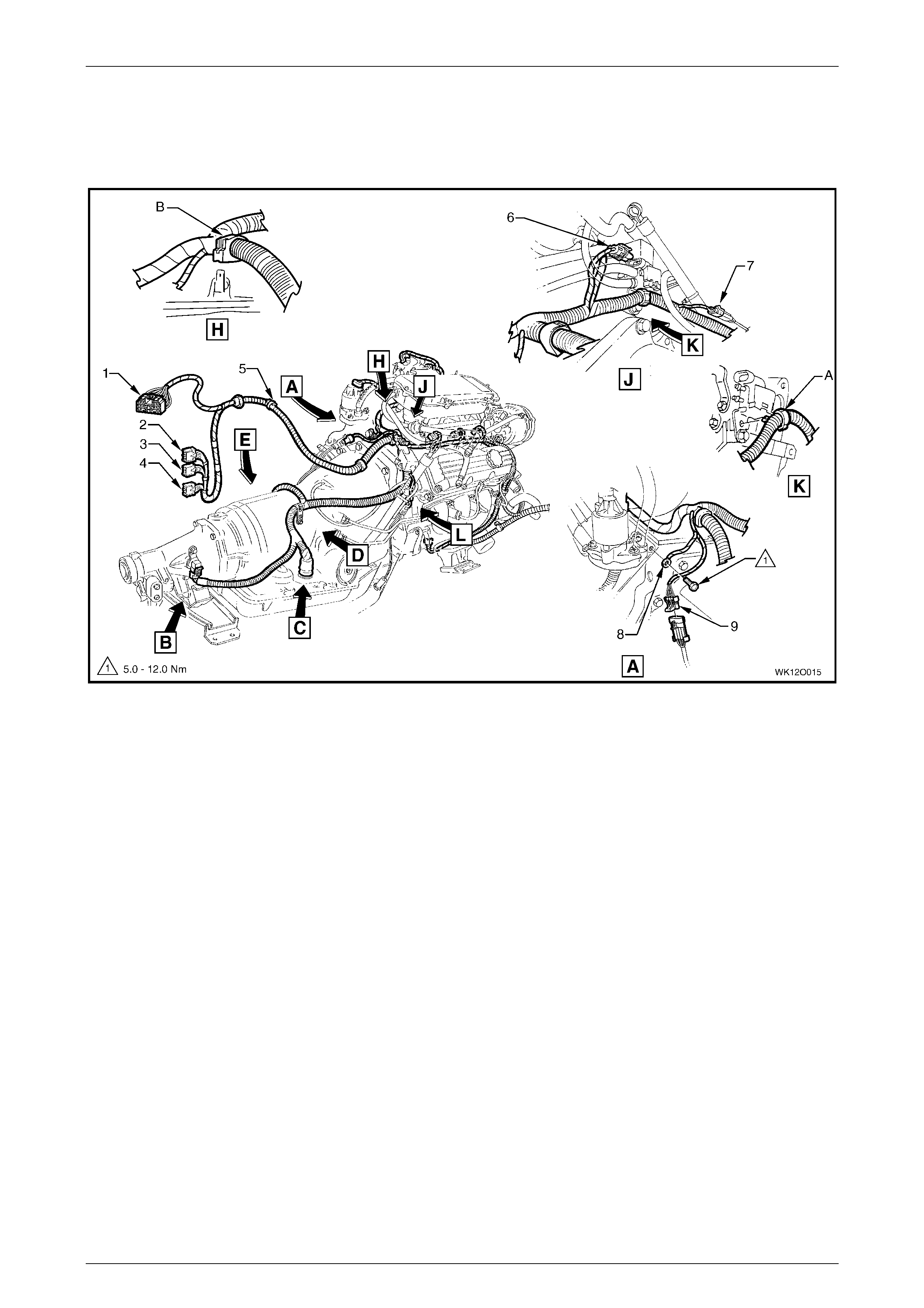
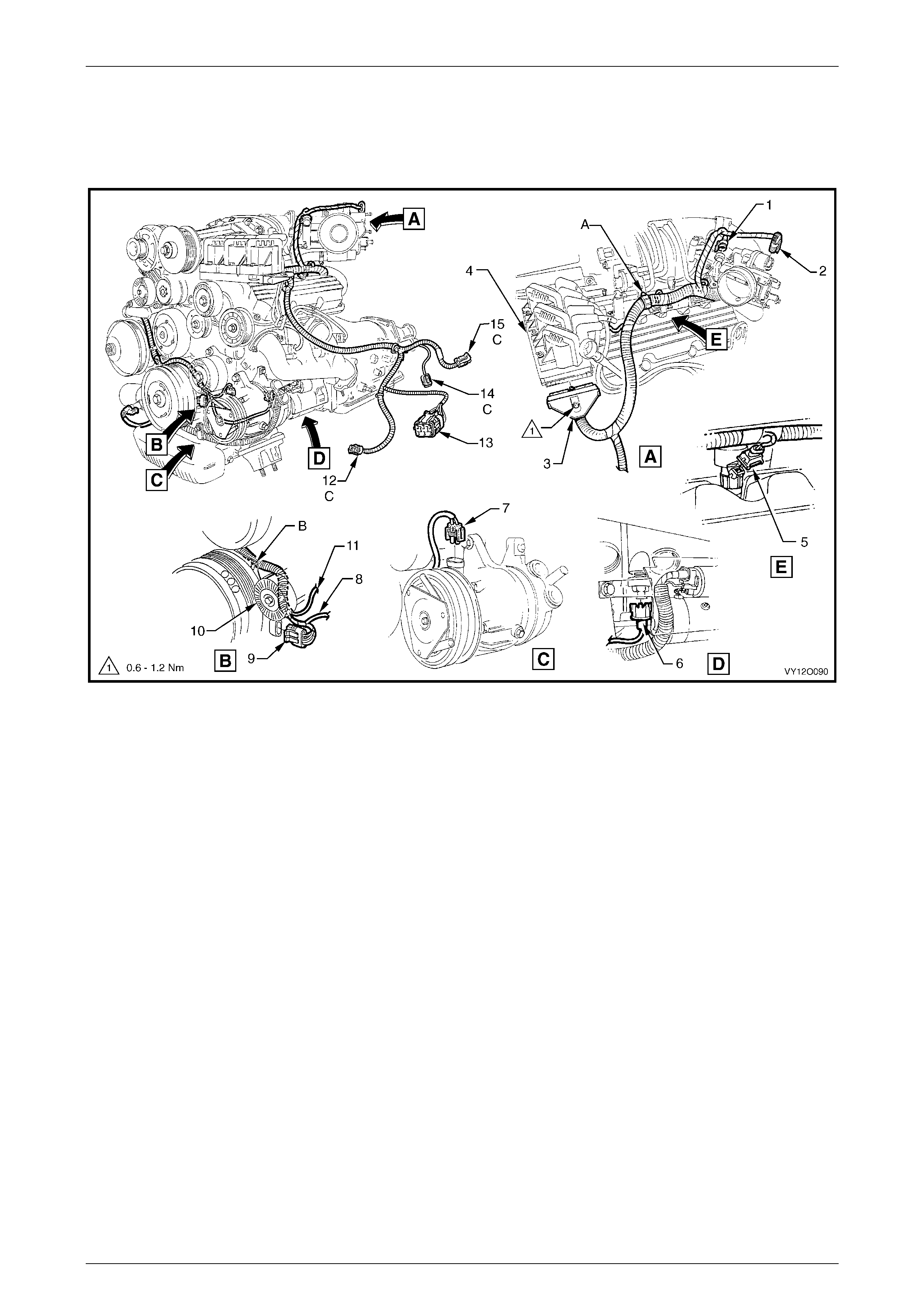
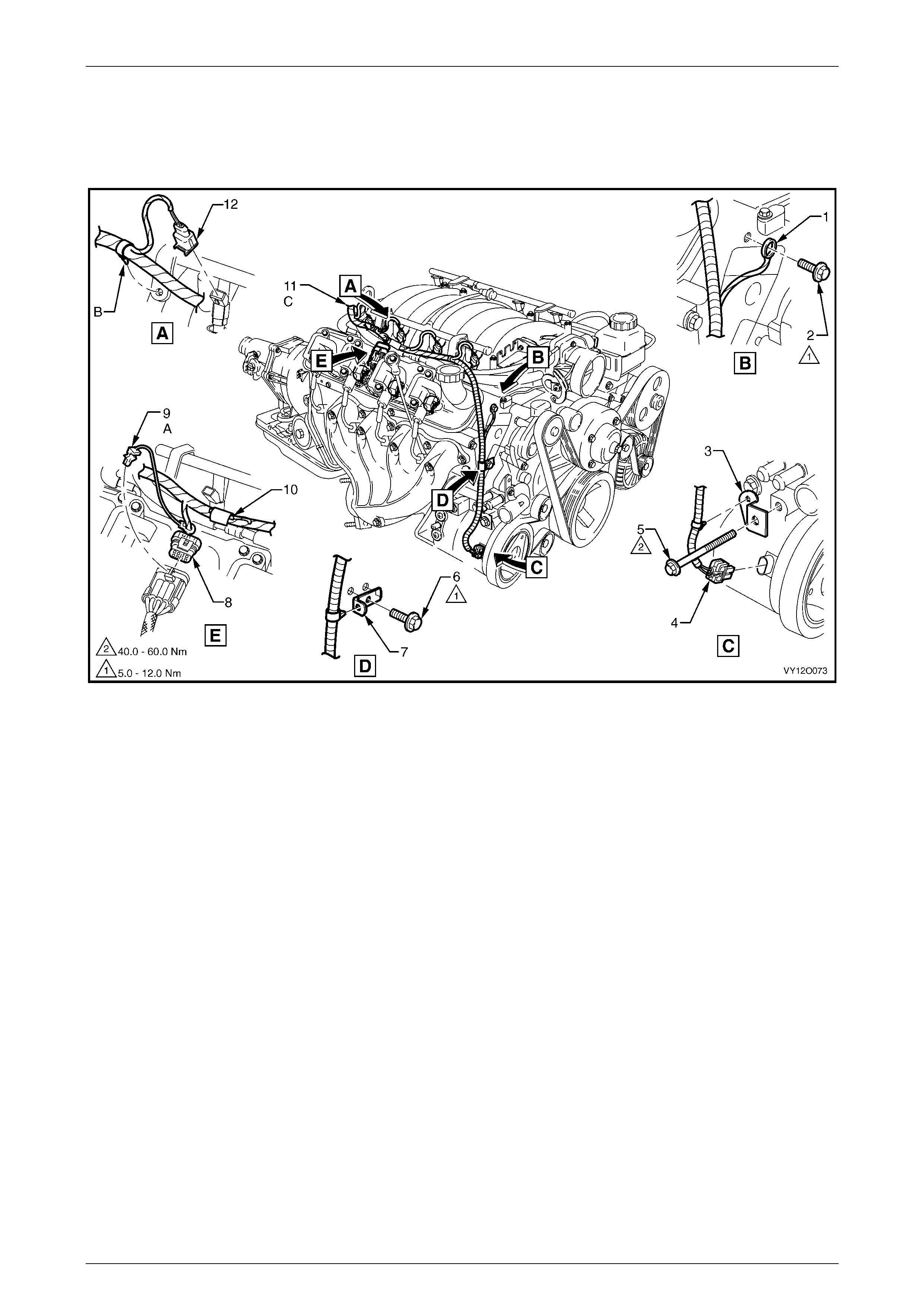
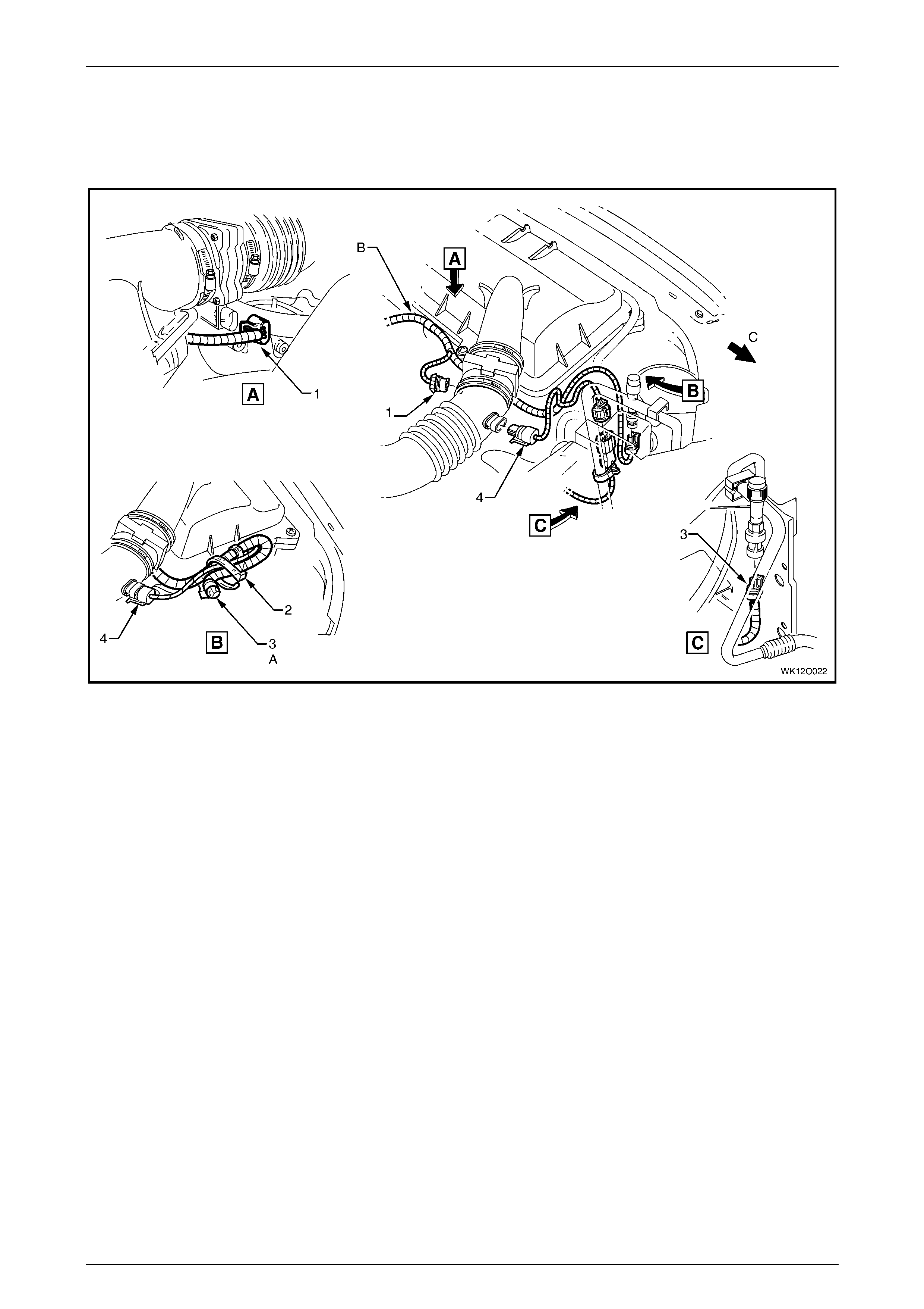
3.6 Powertrain Harness – 3
V6 Engine With Air-condi t i oning or Electronic Climate Control
Figure 12O – 24
Legend
1 Idle Speed Control Actuat or Connector (Y20)
2 Throttle Posit i on Sensor Connector (B82)
3 E.G.R. Valve Connector (Y56)
4 Knock Sensor Connect or (B65 – V6)
5 A/C Clutc h Connector (L7)
6 Suppression Di ode A/ C Compressor (V 6)
7 M.A.S.S Airfl ow Sens or Connect or (B68)
8 Air Temperature Sensor Connect or (B64)
9 Powertrain Harness to Main W i ri ng Harness Connector
(X101)
10 A/C Pressure Sensor Connector (B18)
11 A/C Compressor Lead
12 Knock Sensor Lead, Left-hand Side
13 Crankshaft Position Sensor Connector (B30 – V6)
14 Idler Pulley
15 Fuel Injector Connect or (L2)
A For continuation, refer to 3.7 Powertrain Harnes s – 4.
B Clips bent over t o retain powertrain harness.
C Powertrain harness routed through groove in crankshaft
position sensor shield.
D Secure harness t o manifold as shown.
Fuses, Relays and Wi ring Harnesse s Page 12O–29
Page 12O–29
3.7 Powertrain Harness – 4
V6 Engine With Air-condi t i oning or Electronic Climate Control
Figure 12O – 25
Legend
1 A/C Pressure Sensor Connector (B18)
2 M.A.S.S Air Flow Sensor Connector (B68)
3 Intake Air Temperature Sensor Connector (B 64)
A Powertrain harness sec ured to air box as shown.
B For continuation, refer to 3.11 Powertrain Harness – 8.
Fuses, Relays and Wi ring Harnesse s Page 12O–30
Page 12O–30
3.8 Powertrain Harness – 5
V6 Engine
Figure 12O – 26
Legend
1 Powertrain Harness to Main W i ri ng Harness Connector
(X206)
2 Powertrain Control Module Connec tor (A84 – V6 – X1)
3 Powertrain Control Module Connec tor (A84 – V6 – X2)
4 Powertrain Control Module Connec tor (A84 – V6 – X3)
5 Horn Connector (B 9)
6 Canister Purge Sol enoid Valve Connector (Y123)
7 Heated Oxygen Sensor Connect or (B57 – R)
8 Engine Ground Terminal (X119 – GP5)
9 Heated Oxygen Sensor Connect or (B56 – L)
A Powertrain harness secured to canister purge module as
shown.
B Secure harness t o engi ne as shown.
For views B, C, D & E, refer to 3.9 Powertrain Harness – 6.
Fuses, Relays and Wi ring Harnesse s Page 12O–31
Page 12O–31
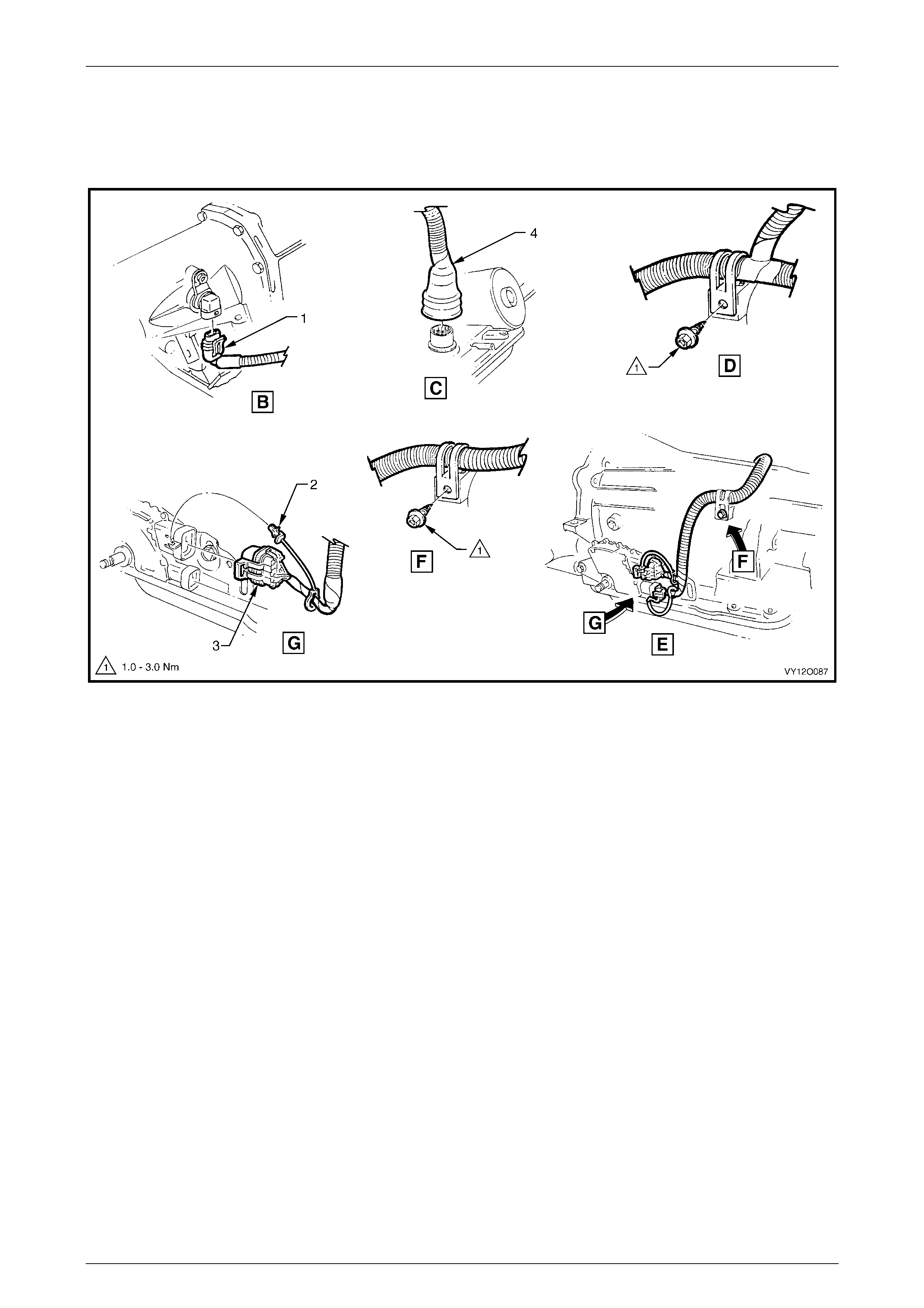
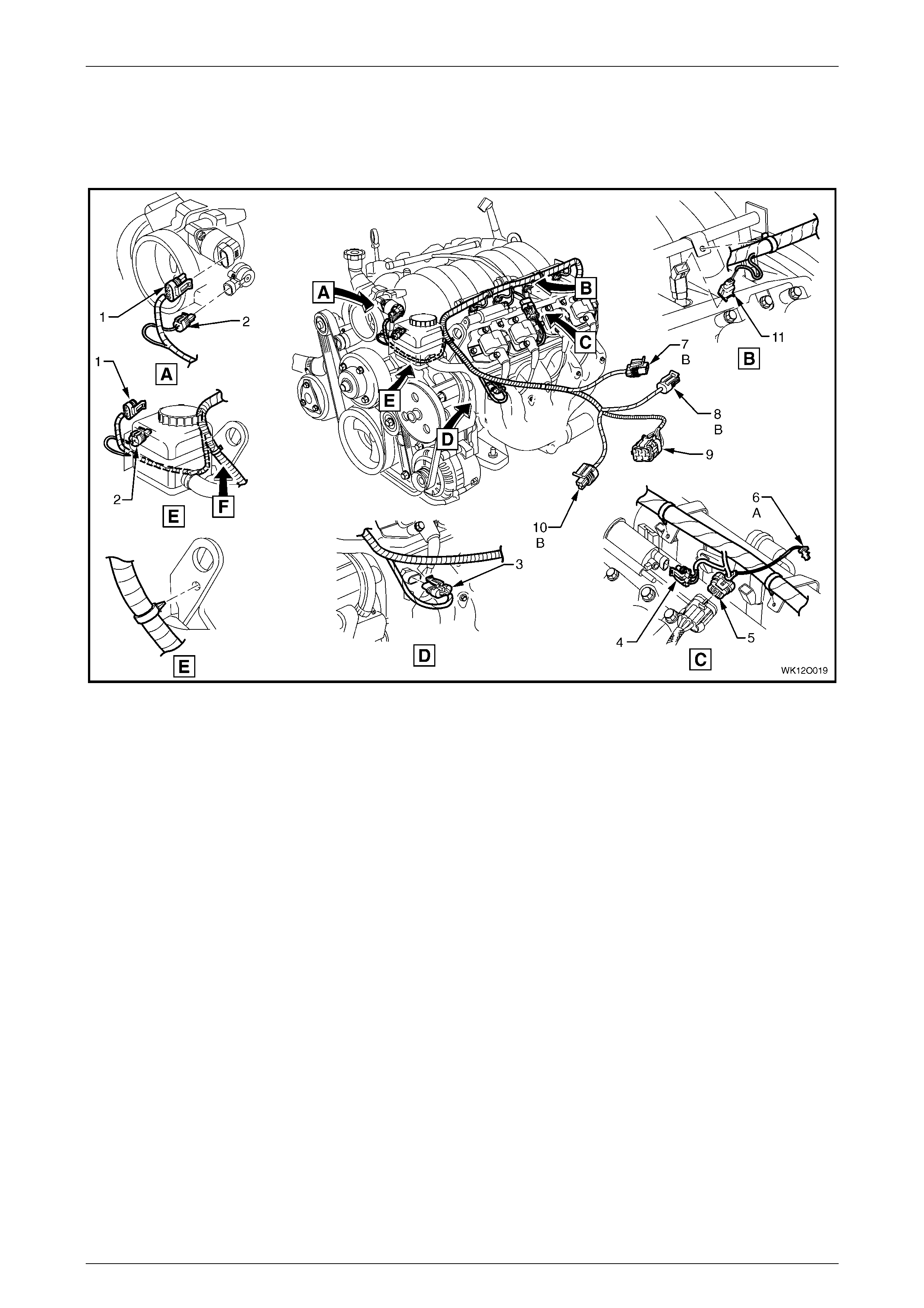
3.9 Powertrain Harness – 6
V6 Engine
Figure 12O – 27
Legend
1 Speed Sender Connector (X121 – X1)
2 C.P.A. Lock
3 Park/Neutral Position Switch Connector (A83)
4 Transmission Ass em bl y Connect or (X121 – X2)
For location of views B, C, D & E, refer to
3.8 Powertrain Harness – 5.
Fuses, Relays and Wi ring Harnesse s Page 12O–32
Page 12O–32
3.10 Powertrain Harness – 7
V6 Supercharged Engine
Figure 12O – 28
Legend
1 Fuel Injector Connect or (L2) – (6 Places)
2 Suppression Di ode A/ C Compressor Connec tor (V6)
3 Clip
4 Bracket – Battery W i ri ng Harness to Engine
5 Powertrain Harness
6 Batte ry Wi ring Harness to Main Wiring Harness Connector
(X106)
7 A.B.S. Bracket Terminal (X119 – G4 – GP3)
8 Batt ery Connector – Positive (G1 – X1)
9 Battery Connector – Negative (G1 – GP1 – X2)
10 Knock Sensor Connect or (B65 – V6)
11 Engine Oil Pressure Indicator Switch Connector (S87)
12 Camshaft Posit i on Sens or Connector (B 28 – V8)
13 Nut
14 Engine Ground Terminal (X119 – GP5)
Fuses, Relays and Wi ring Harnesse s Page 12O–33
Page 12O–33
3.11 Powertrain Harness – 8
V6 Supercharged Engine With Air-conditioning or Electronic Climate Control
Figure 12O – 29
Legend
1 Throttle Posit i on Sensor Connector (B82)
2 Idle Speed Control Actuator Connector (Y20)
3 Electroni c I gnit i on Cont rol Module Connector (A40 – R)
4 Direct Ignition System Control Module
5 Fuel Injector Connect or (L2)
6 Knock Sensor Connect or (B65 – V6)
7 A/C Clutc h Connector (L7)
8 A/C Compressor Connector Lead
9 Crankshaft Position Sensor Connector (B30 – V6)
10 Idler Pulley
11 Knock Sensor Lead, Left-hand Side
12 A/C Pressure Sensor Connector (B18)
13 Powertrain Harness to Main Wi ring Harness Connector
(X101)
14 Intake Air Temperature Sensor Connector (B 64)
15 M.A.S.S Airfl ow Sens or Connect or (B68)
A Powertrain harness secured to bracket as shown.
B Powertrain harness routed through groove in crankshaft
position sensor shield.
C For installation, refer to 3.7 Powertrain Harness – 4.
Fuses, Relays and Wi ring Harnesse s Page 12O–34
Page 12O–34
3.12 Powertrain Harness – 9
V6 Supercharged Engine
Figure 12O – 30
Legend
1 Powertrain Control Module Connec tor (A84 – V6SC – X1)
2 Powertrain Control Module Connec tor (A84 – V6SC – X2)
3 Powertrain Control Module Connec tor (A84 – V6SC – X3)
4 Main Wiring Harness to Powertrain Harness Connector
(X206)
5 Horn Connector (B 9)
6 Boost Control Valve Connector (Y142)
7 Engine Coolant Temperat ure Sensor Connector (B 39)
8 Heated Oxygen Sensor Connect or (B56 – L)
9 Engine Ground Terminal (X119 – GP5)
10 Canister Purge So l enoi d Valve Connector (Y123)
11 Heated Oxygen Sensor Connect or (B57 – R)
A Powertrain harness secured to purge canister solenoid
bracket as shown.
B Powertrain harness secured to bracket as shown.
For views B, C, D & E, refer to 3.9 Powertrain Harnes s – 6.
Fuses, Relays and Wi ring Harnesse s Page 12O–35
Page 12O–35
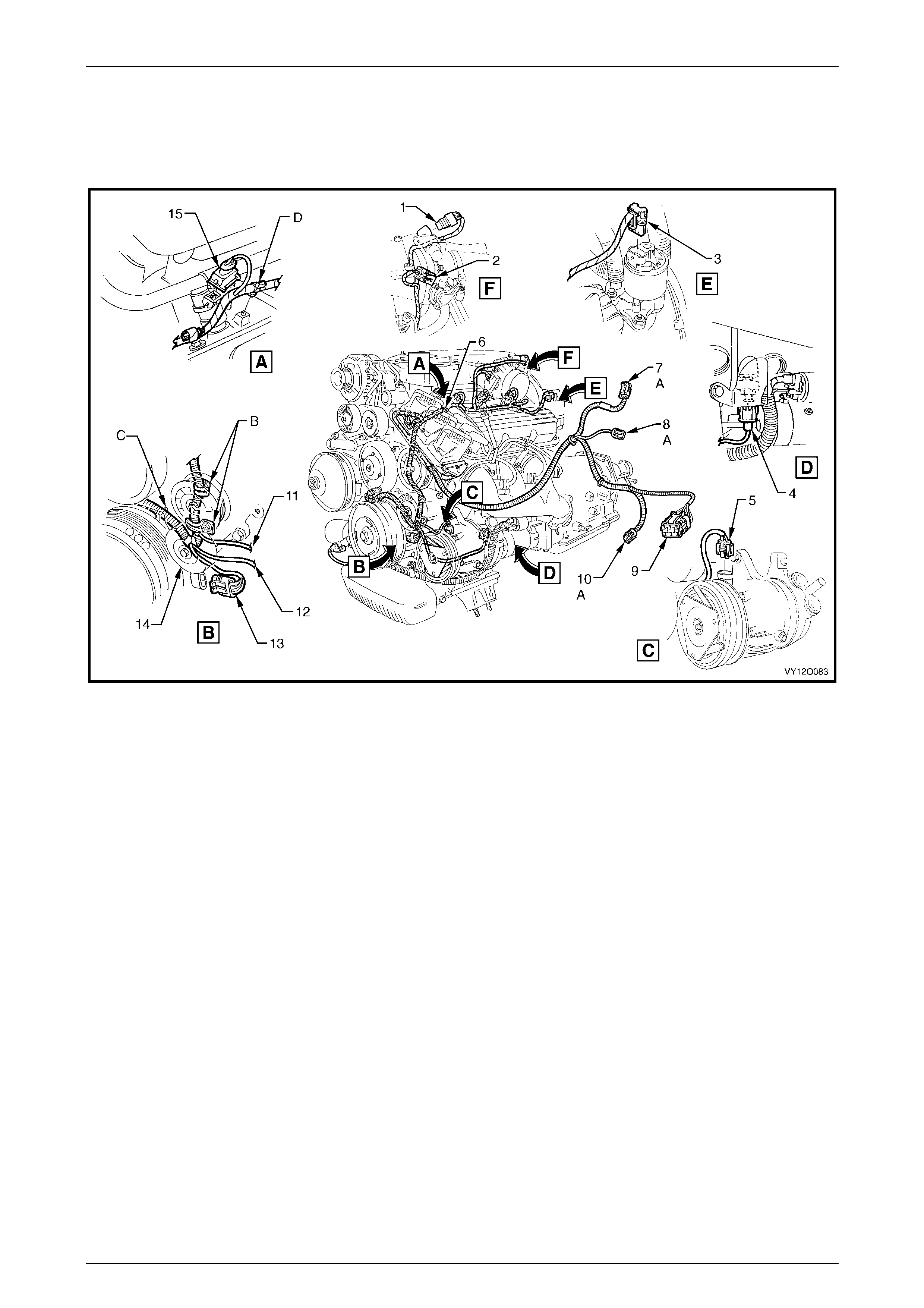
3.13 Powertrain Harness – 10
Gen III V8 Engine
Figure 12O – 31
Legend
1 Powertrain Harness to Engine Earth Terminal (X119 – GP5)
2 Earth Terminal Attachi ng Bolt
3 Air-condi tioni ng Compressor Powertrain Harness Support
Bracket
4 A/C Clutc h Connector (L7)
5 Air-condi tioni ng Compressor Mounting Bolt
6 Powertrain Harness Support Bracket Bolt
7 Powertrain Harness Support Bracket
8 Electroni c I gnit i on Control Module Connector (A40 – R)
9 CPA Lock
10 Suppression Di ode A/ C Compressor Connec tor
11 Powertrain Harness Assembly
12 Fuel Injector Connect or (L2)
A CPA Lock is part of the powertrain harnes s and is inse rt ed
into the ignition modul e connect or on assem bl y.
B Powertrain harness is secured t o bracket in two places on
right-hand si de.
C For continuation, ref er to 3.16 Powertrain Harness – 13.
Fuses, Relays and Wi ring Harnesse s Page 12O–36
Page 12O–36
3.14 Powertrain Harness – 11
Gen III V8 Engine
Figure 12O – 32
Legend
1 Horn Connector (B 9)
2 Theft Deterrent Horn
3 Throttle Actuat or Connect or (Y38)
4 Coolant Surge Tank Bracket
5 Engine Coolant Level Switch Connector (S84)
6 Powertrain Control Module (P CM)
7 Powertrain Control Module Connec tor (A84 – V8 – X2)
8 Powertrain Control Module Connec tor (A84 – V8 – X1)
A Clip fitt ed to brack et before surge tank is fitted.
B Lead for the surge tank low coolant level switch is to be
routed on top of the PCM cover.
C Ensure the PCM connector attaching bolts are not over
tightened.
D Throttle rel axer connect or l ocat i on for dom estic ri ght-hand
drive vehicles onl y.
E For continuation, refer to
3.15 Powertrain Harness – 12,
3.16 Powertrain Harness – 13 and
3.17 Powertrain Harness – 14.
Fuses, Relays and Wi ring Harnesse s Page 12O–37
Page 12O–37
3.15 Powertrain Harness – 12
Gen III V8 Engine
Figure 12O – 33
Legend
1 Idle Speed Control Actuat or Connector (Y20)
2 Throttle Posit i on Sensor Connector (B82)
3 Engine Coolant Temperat ure Sensor Connector (B 39)
4 Canister Purge Sol enoid Valve Connector (Y123)
5 Electroni c I gnit i on Module Connect or (A40 – L)
6 CPA Lock
7 M.A.S.S Airfl ow Sens or Connect or (B68)
8 Intake Air Temperature Sensor Connector (B 64)
9 Powertrain Harness to Main W i ri ng Harness Connector
(X101)
10 A/C Pressure Sensor Connector (B18)
11 Fuel Injector Connect or (L2) – Left-hand Side
A CPA Lock is part of the powertrain harness and is inserted
into the ignition modul e connect or on assem bl y.
B For continuation, refer to 3.18 Powertrain Harness – 15.
Fuses, Relays and Wi ring Harnesse s Page 12O–38
Page 12O–38
3.16 Powertrain Harness – 13
Gen III V8 Engine
Figure 12O – 34
Legend
1 Knock Sensor Connect or (X107)
2 Bolt
3 Powertrain Harness Support Bracket
4 Powertrain Harness Eart h Terminal Attaching Bolt
5 Engine Ground Terminal (X119 – GP6)
6 CPA Lock
7 Park/Neutral Position Switch Connector (A83)
8 Park/Neutral Position & Back-up Switch Connector (S187)
9 Powertrain Harness Attaching Bolt (2 Plac es)
A Clip (two places) bent over after fitting to harness assembly.
B For continuation, refer to 3.14 Powertrain Harness – 11.
C Neutral start, back-up lamp and PRNDL connectors to be
inserted i nto switc h assem bl y before insert i ng harness-
retaining clip into hole.
Fuses, Relays and Wi ring Harnesse s Page 12O–39
Page 12O–39
3.17 Powertrain Harness – 14
Gen III V8 Engine
Figure 12O – 35
Legend
1 M.A.P. Sensor Connect or (B67)
2 Engine Oil Pressure Sensor Connector (B42)
3 Camshaft Posit i on Sens or Connector (B28 – V8)
4 Speed Sender Connector (X121 – X1)
5 Transmission Ass em bl y Connect or (X121 – X2)
6 Crank Angle Sensor Connector (B30 – V8)
A For continuation, refer to 3.14 Powertrain Harness – 11.
Fuses, Relays and Wi ring Harnesse s Page 12O–40
Page 12O–40
3.18 Powertrain Harness – 15
Gen III V8 Engine
Figure 12O – 36
Legend
1 M.A.P. Sensor Connect or (B67)
2 Cable Tie
3 A/C Pressure Sensor Connector (B18)
4 Intake Air Temperature Sensor Connector (B 64)
A View for vehicl es fitt ed with non–ECC air-conditioni ng.
B For continuation, refer to 3.15 Powertrain Harness – 12.
C Front of vehicle.

Fuses, Relays and Wi ring Harnesse s Page 12O–41
Page 12O–41
3.19 Powertrain Harness – 16
V6 Engine and V6 Supercharged Engine
Figure 12O – 37
Legend
1 Cowl Panel – Left-hand Side
2 Body Wiring Harness
3 Powertrain Harness
4 Powertrain Control Module Mounting Bracket
5 Powertrain Control Module
6 Powertrain Control Module Connec tor (A84 – V6 – X2)
7 Powertrain Control Module Connec tor (A84 – V6 – X1)
8 Powertrain Control Module Connec tor (A84 – V6 – X3)
A Front of vehicle.
Fuses, Relays and Wi ring Harnesse s Page 12O–42
Page 12O–42
3.20 Powertrain Harness – 17
Gen III V8 Engine
Figure 12O – 38
Legend
1 Mounting Bracket
2 Throttle Relaxer Control Module
3 Powertrain Interface Module
4 Powertrain Interface Module Connector (A5)
5 Throttle Actuat or Control Module Connect or (A 111)
A For continuation, refer to 3.14 Powertrain Harness – 11.
B Front of vehicle.
Fuses, Relays and Wi ring Harnesse s Page 12O–43
Page 12O–43
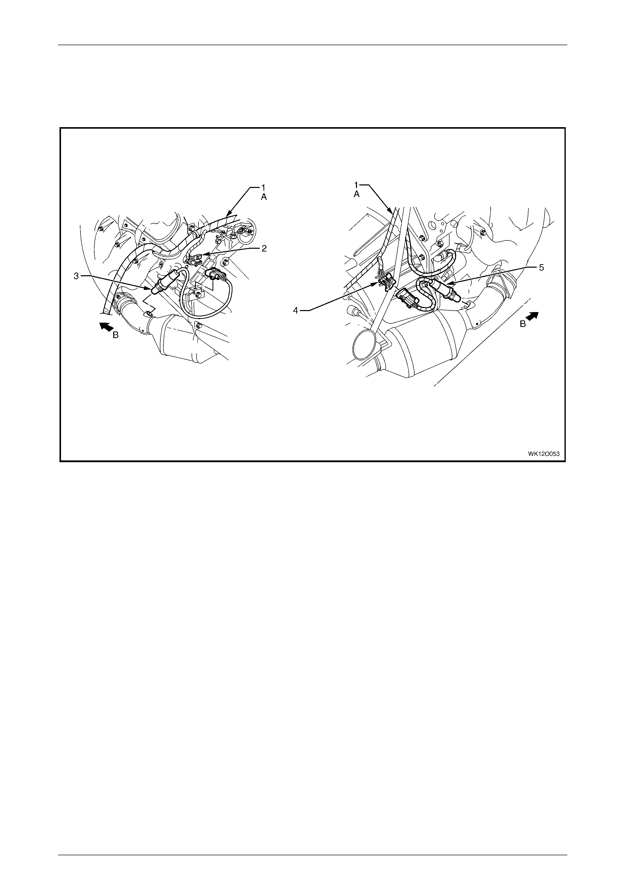
3.21 Powertrain Harness – 18
Gen III V8 Engine
Figure 12O – 39
Legend
1 Powertrain Harness
2 Heated Oxygen Sensor Connect or (B56 – L)
3 Heated Oxygen Sensor – Left-hand Side
4 Heated Oxygen Sensor Connect or (B57 – R)
5 Heated Oxygen Sensor – Right-hand Side
A For continuation, refer to 3.16 Powertrain Harness – 13.
B Front of vehicle.
Fuses, Relays and Wi ring Harnesse s Page 12O–44
Page 12O–44
3.22 Main Wiring Harness – 1
Engine Compartment – RHD
Figure 12O – 40
Legend
1 Windshield Wiper Motor Connec t or (M17)
2 Brake Pressure Differential Connector (S37)
3 Electronic Braking and Traction Control Module Connector
(A37)
4 Cruise Control Connect or (A18)
5 Main Wiring Harness to Battery Wiring Harness Connec tor
(X106)
6 Engine Wiring Harness J u nct i on Connector (X100)
7 Front Wheel Speed Sensor Connector (B52 – R)
8 A.B.S. Brack et Connector (X119 – G3 – GP3)
9 Ground Connector (X157)
10 Fusible Link Supply Connect or (X86 – A)
11 Turn Signal Lamp Connector (E 76 – R)
12 Headlamp Connect or (E83 – R)
13 Windshield Wiper and Windshield Washer
Connector (M19)
14 Front Fog & Cornering Lamp Connector (X110)
15 Horn Connectors (B9 – R)
16 Ambient Air Temperature Sensor Connector (B 23)
17 Hood Theft Deterrent Connect ors (S135)
18 Engine Cooling Fan Connector (M7 – X1)
19 Main Wiring Harness to Powertrain Harness Connector
(X101)
20 Horn Connectors (B9 – L)
21 Front Fog & Cornering Lamp Connector (X111)
22 Headlamp Connect or (E83 – L)
23 Turn Signal Lamp Connector (E 76 – L)
24 Front Wheel Speed Sensor Connector (B52 – L)
25 Sealing Patch Grommet
26 Grommet Insert
27 Instrument Panel to Body Ground Strap Terminal
(X118 – GP9)
28 Body to Instrum ent Panel Ground Strap
29 Body to Instrument P anel Ground Strap Terminal
(X118 – GP10)
For views C and D, refer to 3.23 Main Wi ri ng Harness – 2.
For view E, refer to 3.2 Main W i ri ng Harness – 6.
For view F, refer to 3.2 Main Wi ri ng Harness – 8 .
Fuses, Relays and Wi ring Harnesse s Page 12O–45
Page 12O–45
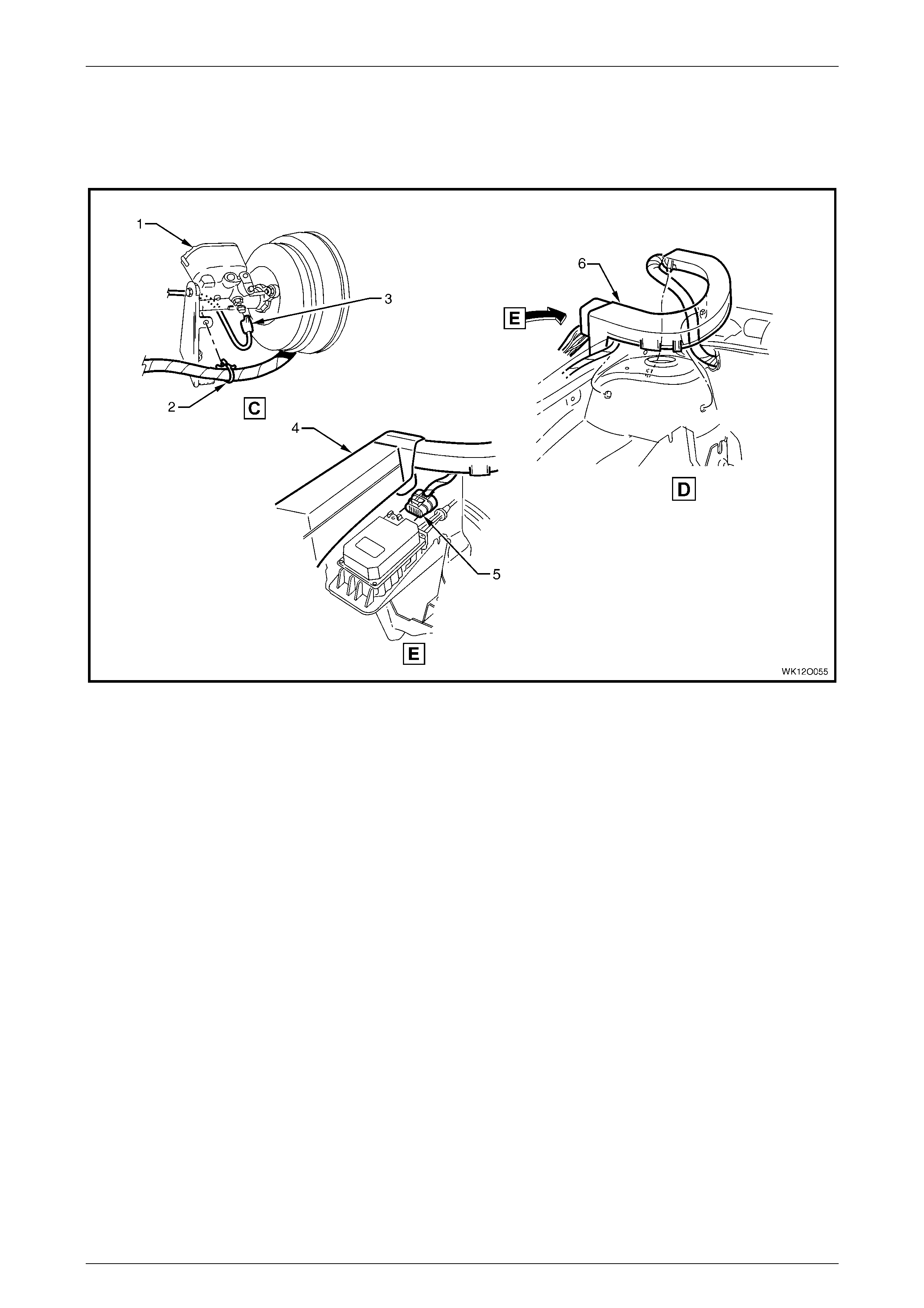
3.23 Main Wiring Harness – 2
Protector Assembly, Cruise Control and Engine Harness Connectors
Figure 12O – 41
Legend
1 Brake Master Cyl i nder and Brak e Boost er
2 Wiring Harness t o Brake Mast er Cylinder Support Retaining
Clip
3 Brake Pressure Differential Connector (S37)
4 Engine Wiring Harness Junction Connecter Cover
5 Cruise Control Connect or (A18)
6 Harness Former
For location of views C and D, refer to
3.22 Main Wiring Harness – 1.
Fuses, Relays and Wi ring Harnesse s Page 12O–46
Page 12O–46
3.24 Main Wiring Harness – 3
Under Hood Fuse & Relay Panel and Wiper Motor Connectors
Figure 12O – 42
Legend
1 Engine Wiring Harness Junction Connector Cover
2 Engine Wiring Harness J u nct i on Connector (X100)
3 Attaching Screw
4 Windshield Wiper Motor Connec t or (M17)
5 Firewall Clip (2 Places)
Fuses, Relays and Wi ring Harnesse s Page 12O–47
Page 12O–47
3.25 Main Wiring Harness – 4
Front Lamps, Body Earth and Washer Pump Connectors
Figure 12O – 43
Legend
1 Attaching Stud – Body Earth
2 Body Ground Connector (X157 – GP2)
3 Washer – Body Ground
4 Attachi ng Nut – Body Ground
5 Headlamp Connect or (E83)
6 Turn Signal Lamp Connector (E 76)
7 Windshiel d Washer Connect or (M19)
8 Windshield Washer Reservoir
9 Battery Tray
A Harness leads attached to right-hand side wheelhouse as
shown.
Early production vehicles
Late production vehicles
Fuses, Relays and Wi ring Harnesse s Page 12O–48
Page 12O–48
3.26 Main Wiring Harness – 5
Headlamp, Park Lamp and Turn Indicator Connectors
Figure 12O – 44
Legend
1 Main Wiring Harness
2 Turn Signal Lamp Connector (E 76)
3 Turn Signal Lamp Socket
4 Headlamp Connect or (E83)
5 Headlamp Low Beam Dust Cover
6 Headlamp Adjuster
7 Headlamp High Beam Dust Cover
Fuses, Relays and Wi ring Harnesse s Page 12O–49
Page 12O–49
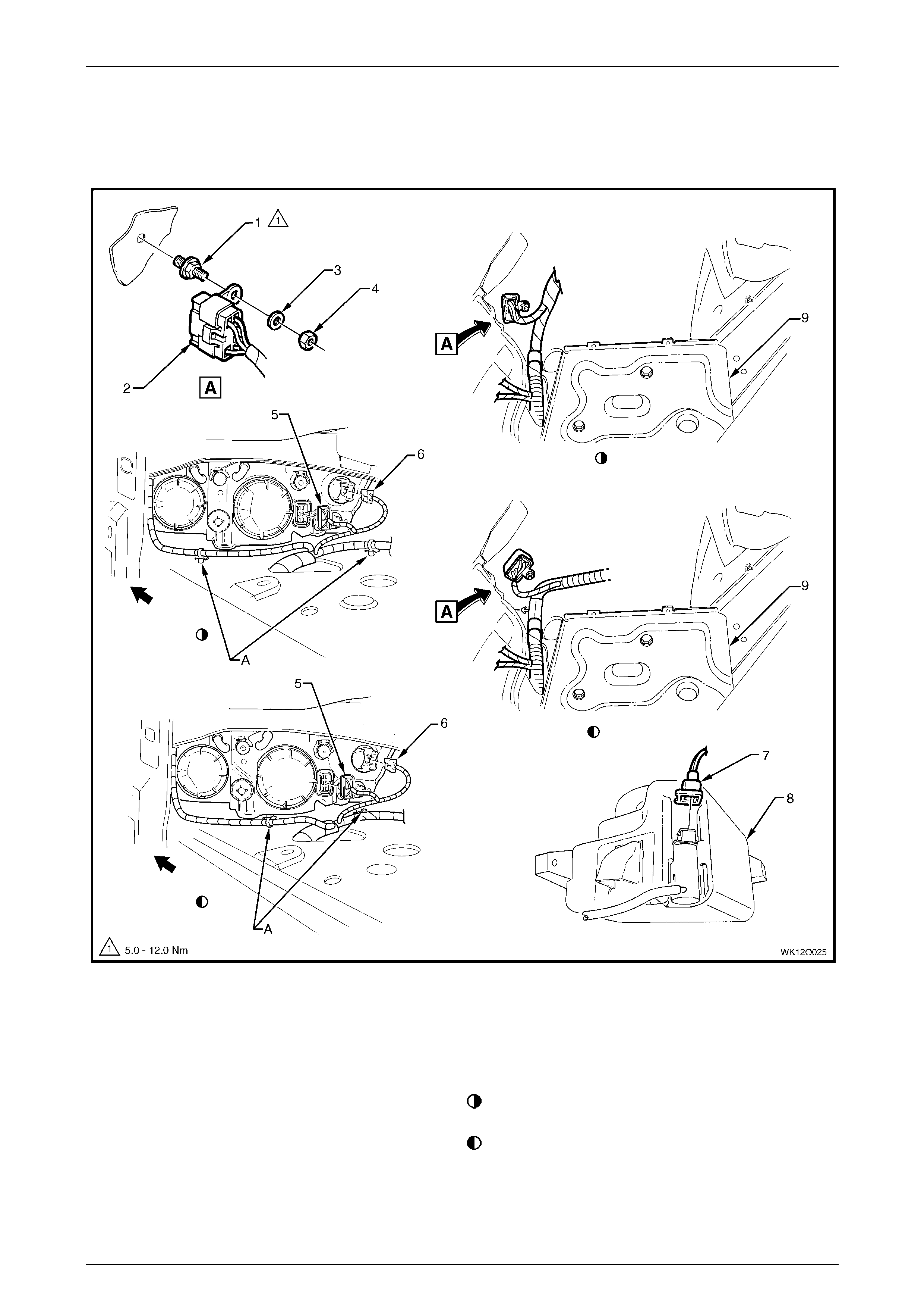
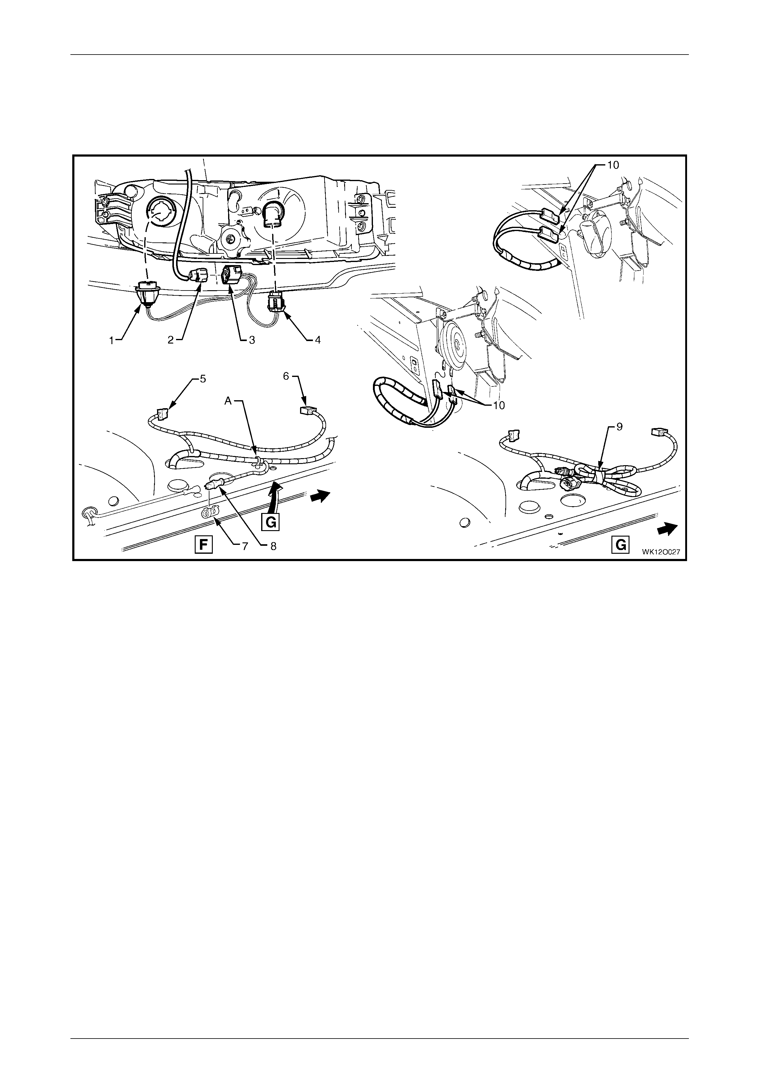
3.27 Main Wiring Harness – 6
Ambi ent Sensor, Air-condit i oning Fan and Theft Deterrent Connectors
Figure 12O – 45
Legend
1 Hood Theft Deterrent Switch Connectors (S135)
2 Main Wiring Harness To Engine Cooling Fan Connector
(M7 – X1)
3 Ambient Air Temperature Sensor Connector (B 23)
4 Attaching Screw – Hood Theft Deterrent Switch
5 Hood Theft Deterrent Switch
A Harness att ached t o side rail assembly as shown.
B Blue strap to be aligned with centre line of vehicle as shown.
C Harness attached to radiator lower support assembl y as
shown (5 places).
D Front of vehicle.
For view C, refer to 3.28 Main Wiring Harness – 7.
For location of view E, refer t o 3.22 Main Wiring Harness – 1.
Fuses, Relays and Wi ring Harnesse s Page 12O–50
Page 12O–50
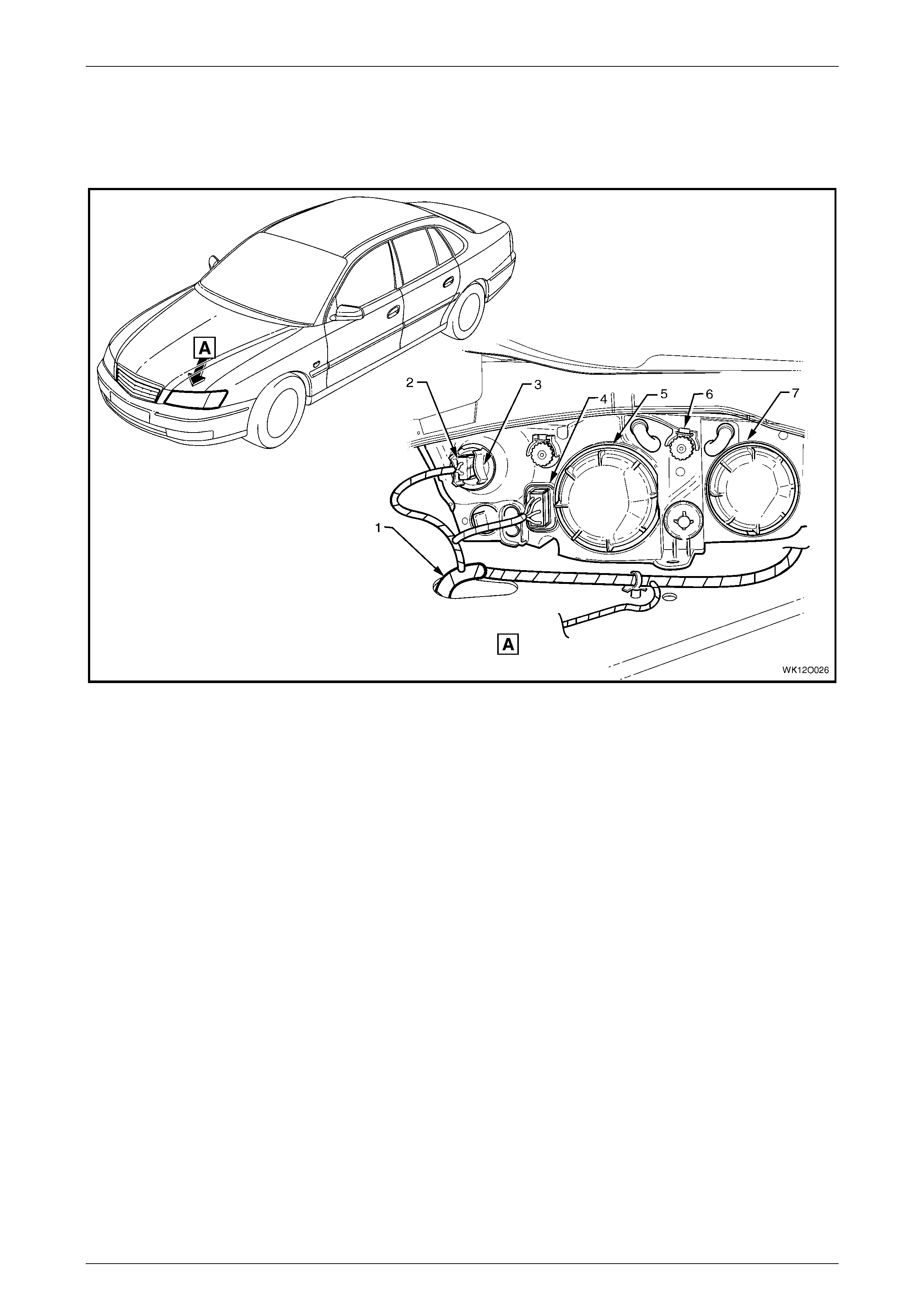
3.28 Main Wiring Harness – 7
Ambi ent Sensor, Air-condit i oning Fan and Theft Deterrent Connectors
Figure 12O – 46
Legend
1 Main Wiring Harness
2 Condenser and Ambient Sens or
3 Ambient Air Temperature Sensor Connector (B 23)
4 Hood Theft Deterrent Switch Connectors (S135)
5 Engine Cooling Fan Connector (M7 – X1)
A Harness attached t o front wheelhous e panel brack et as
shown.
B Connectors f eed through f ront end panel assembly to hood
theft deterrent switc h.
Fuses, Relays and Wi ring Harnesse s Page 12O–51
Page 12O–51
3.29 Main Wiring Harness – 8
Cornering Lamp, Fog Lamp and Horn Connectors
Figure 12O – 47
Legend
1 Front Cornering Lamp Connect or (E17)
2 Main Wiring Harness t o Fog Lamp & Cornering Lamp
Harness Connect or (X111)
3 Fog Lamp & Cornering Lamp Harness to Main Wiring
Harness Connect or (X111)
4 Fog Lamp Connector (E69)
5 Turn Signal Lamp Connector (E 76)
6 Headlamp Connect or (E83)
7 Front Wheel Speed Sensor Connector Retainer
8 Front Wheel Speed Sensor Connector (B52)
9 Front Wheel Speed Sensor Tie-back
10 Horn Connectors (B9)
A Harness attached t o wheelhouse panel as shown – left-hand
side.
For location of View F, refer to 3.22 Main Wi ri ng Harness – 1 .
Fuses, Relays and Wi ring Harnesse s Page 12O–52
Page 12O–52
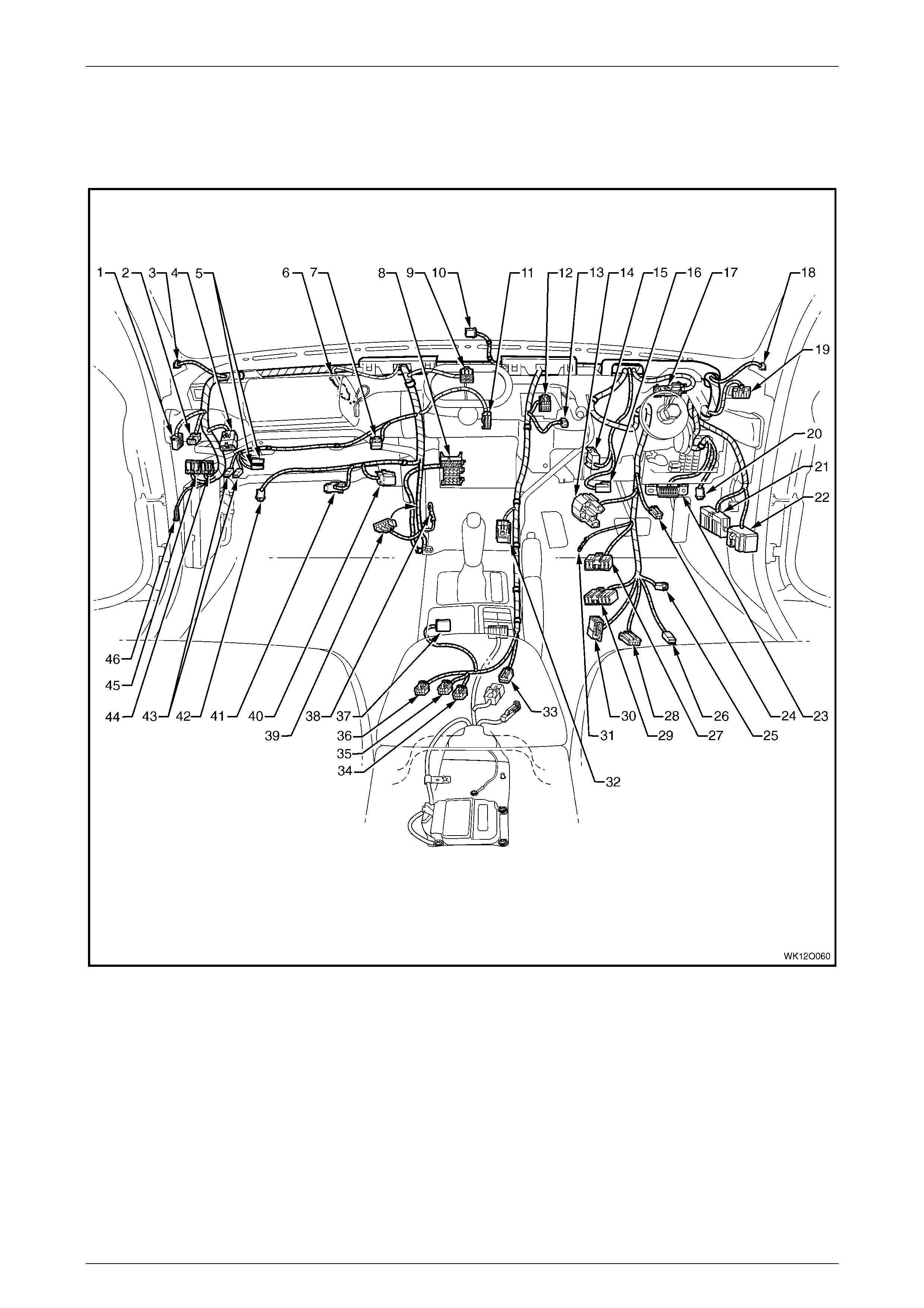
3.30 Main Wiring Harness – 9
Cockpit Module – RHD
Figure 12O – 48

Fuses, Relays and Wi ring Harnesse s Page 12O–53
Page 12O–53
Legend
1 Main Wiring Harness to Body Wiring Harness Connect or
(X202)
2 Main Wiring Harness t o Global Positioning S yst em
Harness Connect or (X207)
3 Radio Front Speaker Dash Upper Connector (B 112 – L)
4 Main Wiring Harness to Powertrain Harness Connector
(X206)
5 Instrument P anel Compartment Lamp Switch Connectors
(S142)
6 Main Wiring Harness t o Pass enger Air Bag Harness
Connector (X205)
7 Rear Compartment Lid Release Switc h Connector
(S195)
8 Radio, Clock & CD Pl ayer Connector (A133 – X1)
9 Multi Functi on Displ ay Connect or (P5)
10 Ambient Light Sensor Connect or (B55)
11 Blower Motor & A/C Compress or Connector (A14 – X1)
12 Trip Odometer Reset Switch Connector (S237)
13 Inside Air Temperature Sensor Connect or (B59)
14 Ignition & Start Switch Connector (S149 – X1)
15 Stop Lamp, Traction & Cruise Control Releas e Switc h
Connector (S 220 – X1)
16 Stop Lamp, Traction & Cruise Control Releas e Switc h
Connector (S 220 – X2)
17 Instruments Connector (P3)
18 Radio Front Speaker Dash Upper Connector (B 112 – R)
19 Headlamp Automatic Control Switch Connect or (S 125)
20 Right-hand Front Step Well Lamp Connector (E 105)
21 Main Wiring Harness to Body Wiring Harness Connect or
(X200)
22 Main Wiring Harness to Body Wiring Harness Connect or
(X201)
23 Wiring (Diagnostic) Connector (X40)
24 Windshiel d Wiper Dwell Module Connect or (R23)
25 Igniti on Lock Cyl i nder Bulb Connect or (E30)
26 Ignition & Start Switch Connector (S149 – X2)
27 Windshield Wiper and Washer Switch Connector (S247)
28 Cruise Control Switc h Connect or (S43)
29 Turn Signal & Headlamp Switch Connector (S231)
30 Steering Wheel Clock Spring Coil Connector (X116)
31 Igniti on & Start Switch Connect or (S149 – GP15 – X3)
32 Front Cigar Lighter Connect or (X113 – F)
33 Main Wiring Harness to Body Wiring Harness Connect or
(X303)
34 LPG Switch Connector (S 118)
35 Hazard Warning S witch Connector (S120)
36 Main Wiring Harness t o Consol e Wiring Harness Connector
(X309)
37 Main Wiring Harness to Transmission Selector Harness
Connector (X301)
38 Radio Ground Terminal (X118 – GP8)
39 Inline to Radio & Mobile Telephone Connector (X155)
40 Blower & Air Inlet Connector (A13)
41 Blower Motor Connector (M3 – RHD)
42 Left-hand Front Foot Well Lamp Connector (E105)
43 Instrument P anel Compartment Lamp Connectors (E82)
44 Communic ation Centre Call Connector (A158 – X2)
45 Communic ation Centre Call Connector (A158 – X1)
46 Radio Antenna Amplif i er Connect or (N3)
Fuses, Relays and Wi ring Harnesse s Page 12O–54
Page 12O–54
3.31 Main Wiring Harness – 10
Cockpit Module – RHD
Figure 12O – 49
Legend
1 Main Wiring Harness To Body Wiring Harness Connector
(X201)
2 Body Wiring Harness To Main Wiring Harness Connec tor
(X201)
3 Body Wiring Harness To Main Wiring Harness Connec tor
(X200)
4 Main Wiring Harness To Body Wiring Harness Connector
(X200)
5 Body Control Module
6 Body Control Module Connect or (A15 – X1)
7 Body Control Module Connect or (A15 – X2)
8 Body Control Module Connect or (A15 – X3)
9 Body Control Module Connect or (A15 – X4)
Fuses, Relays and Wi ring Harnesse s Page 12O–55
Page 12O–55
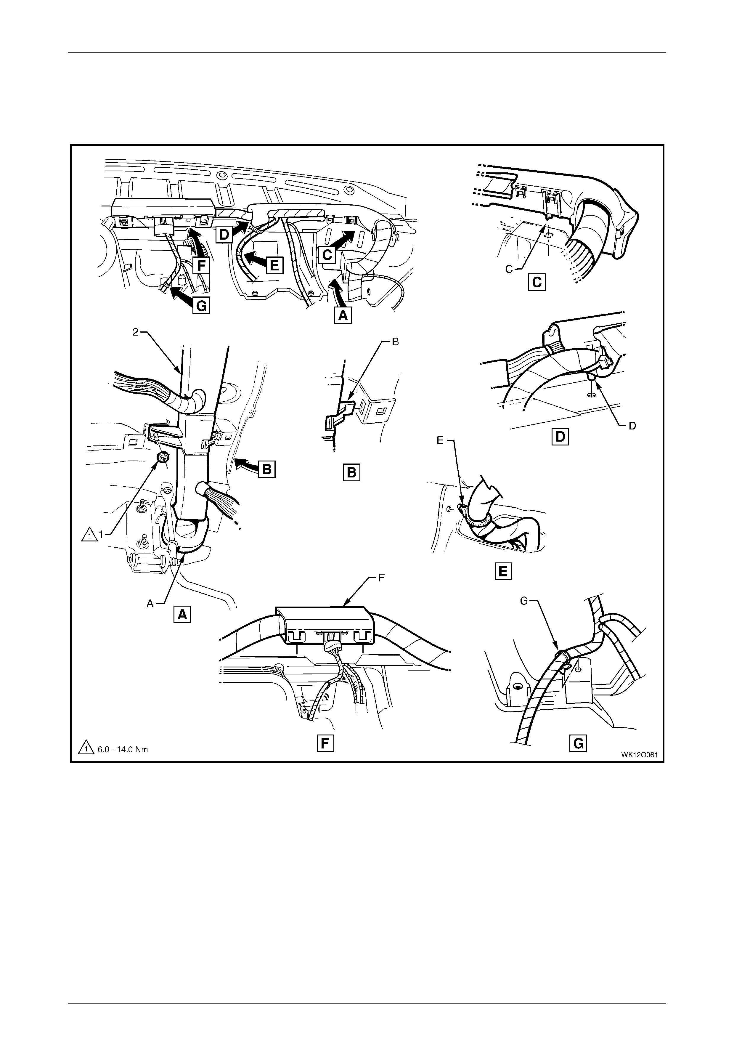
3.32 Main Wiring Harness – 11
Cockpit Module – RHD
Figure 12O – 50

Fuses, Relays and Wi ring Harnesse s Page 12O–56
Page 12O–56
Legend
1 Attachi ng Nut – Wiring Harness Retainer To Instrum ent
Panel
2 Main Wiring Harness Cabl e Retainer
A Refer to 3.22 Main Wi ri ng Harness – 1 section for sealing
patch grommet and insert instal lation.
B Main wiring harness form er att ached to inst rument panel
cover assem bl y as shown.
C Main wiring harness form er att ached to inst rument panel
cover assem bl y as shown.
D Main wiring harness form er att ached to inst rument panel
cover assem bl y as shown.
E Main wiring harness retai ner att ached to steering column
bracket as shown.
F Main wiring harness former att ached to instrument panel
cover assem bl y as shown.
G Main wiring harnes s retainer attached to vehicle as shown.
Fuses, Relays and Wi ring Harnesse s Page 12O–57
Page 12O–57
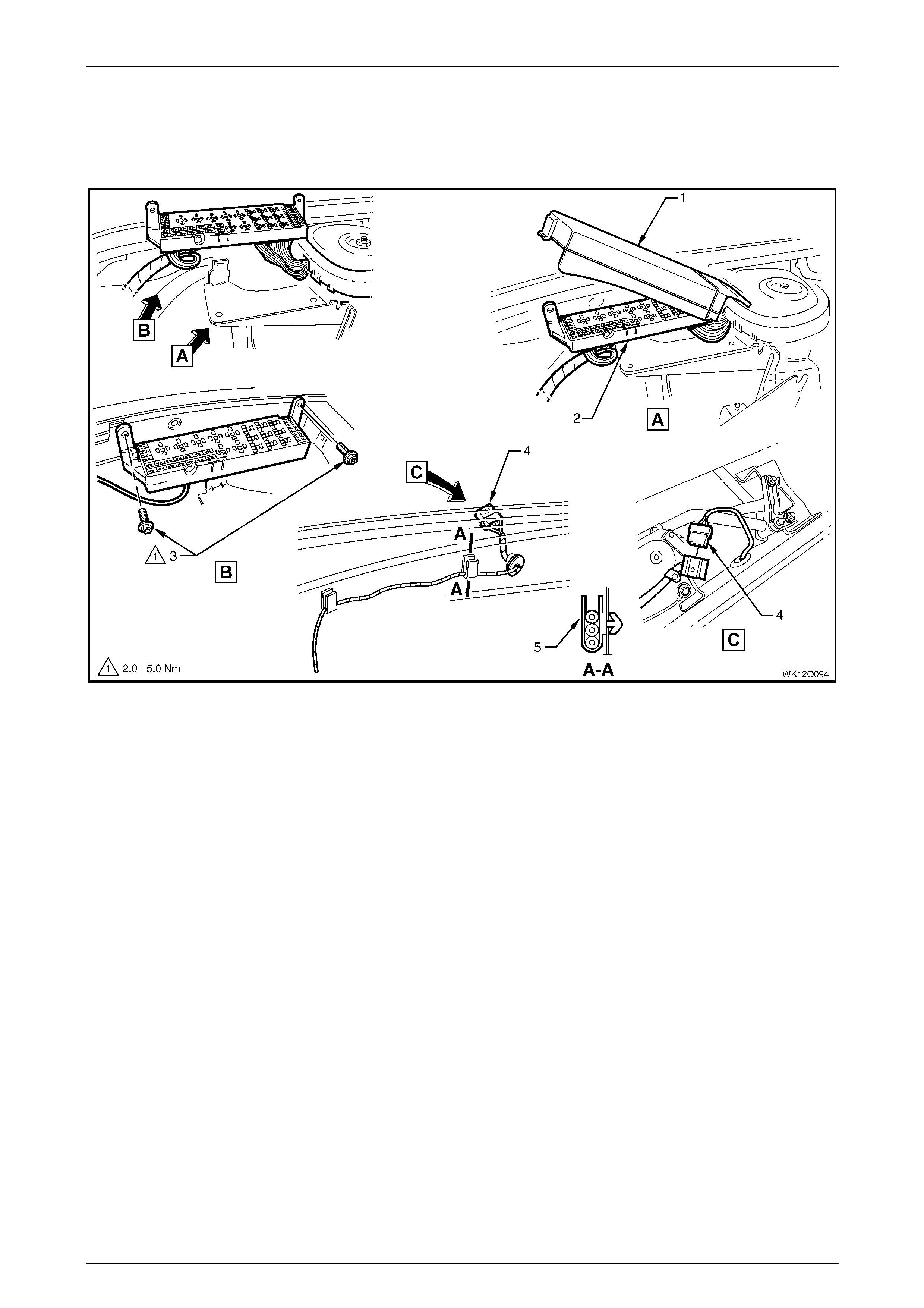
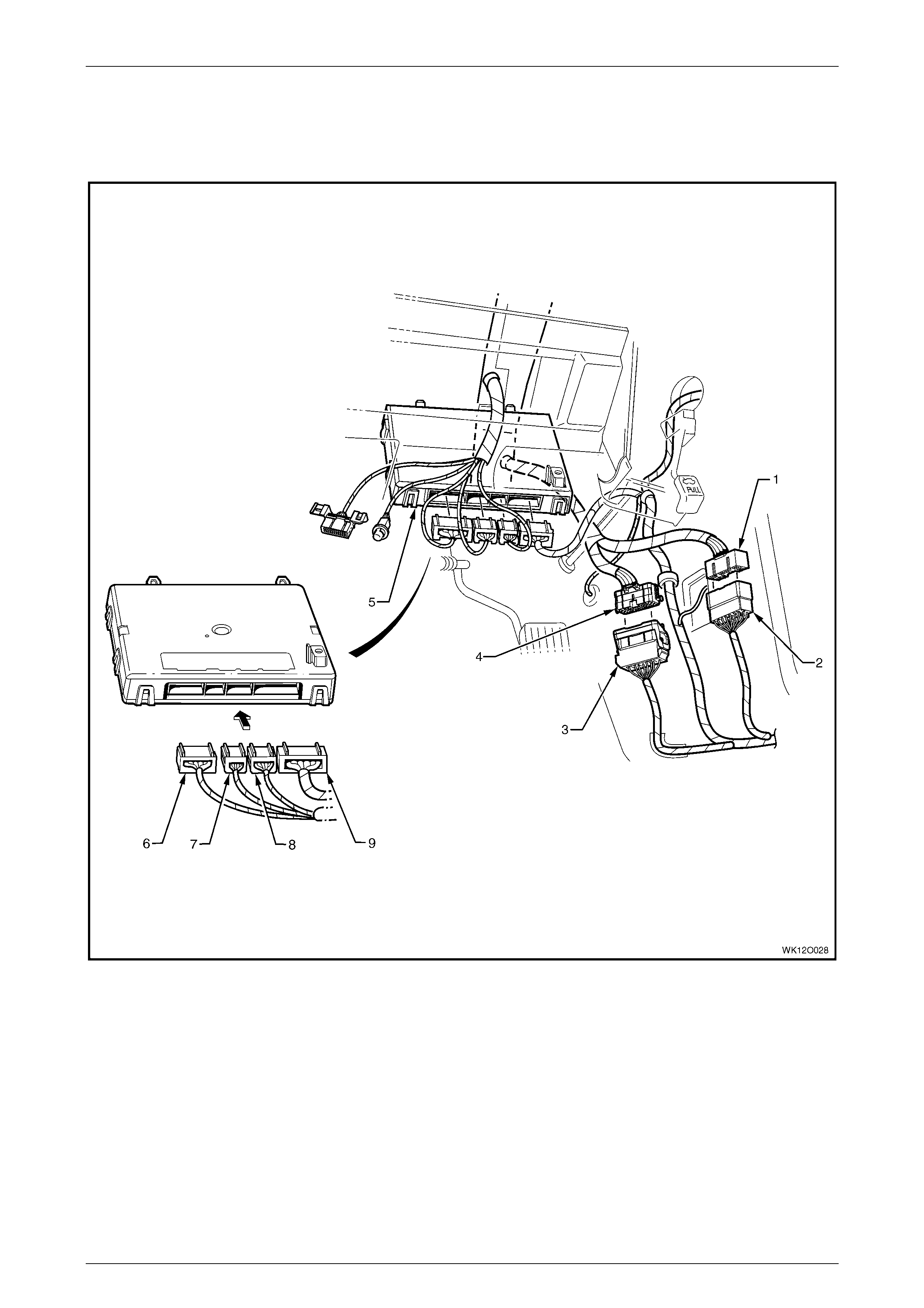
3.33 Main Wiring Harness – 12
Fuse Block and Body Contr o l M odule – RHD
Figure 12O – 51
Legend
1 Instrument P anel Wiring Harness Fuse Block Support
Bracket
2 Instrument P anel Wiring Harness Fuse Block (X129)
3 Body Control Module
4 Attachi ng Screw, Body Control Module Mounting
To Support
A Instrument panel wiring harnes s fuse block – installed as
shown.
B For installa tion of relays, fuses and circuit breakers, refer to
1 General Information.
C Main wiring harness form er, ref e r to
3.32 Main Wiring Harness – 11.
Fuses, Relays and Wi ring Harnesse s Page 12O–58
Page 12O–58
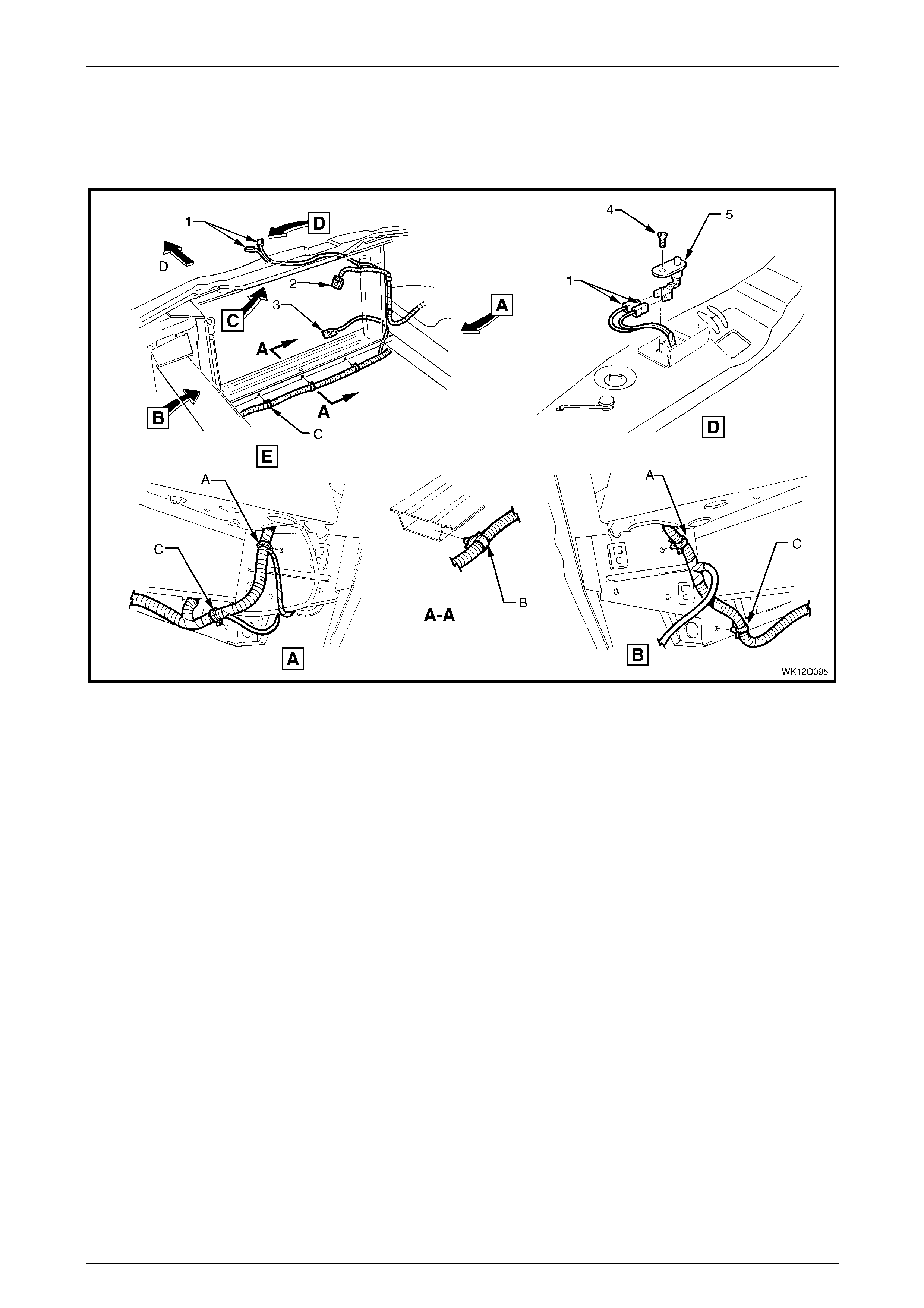
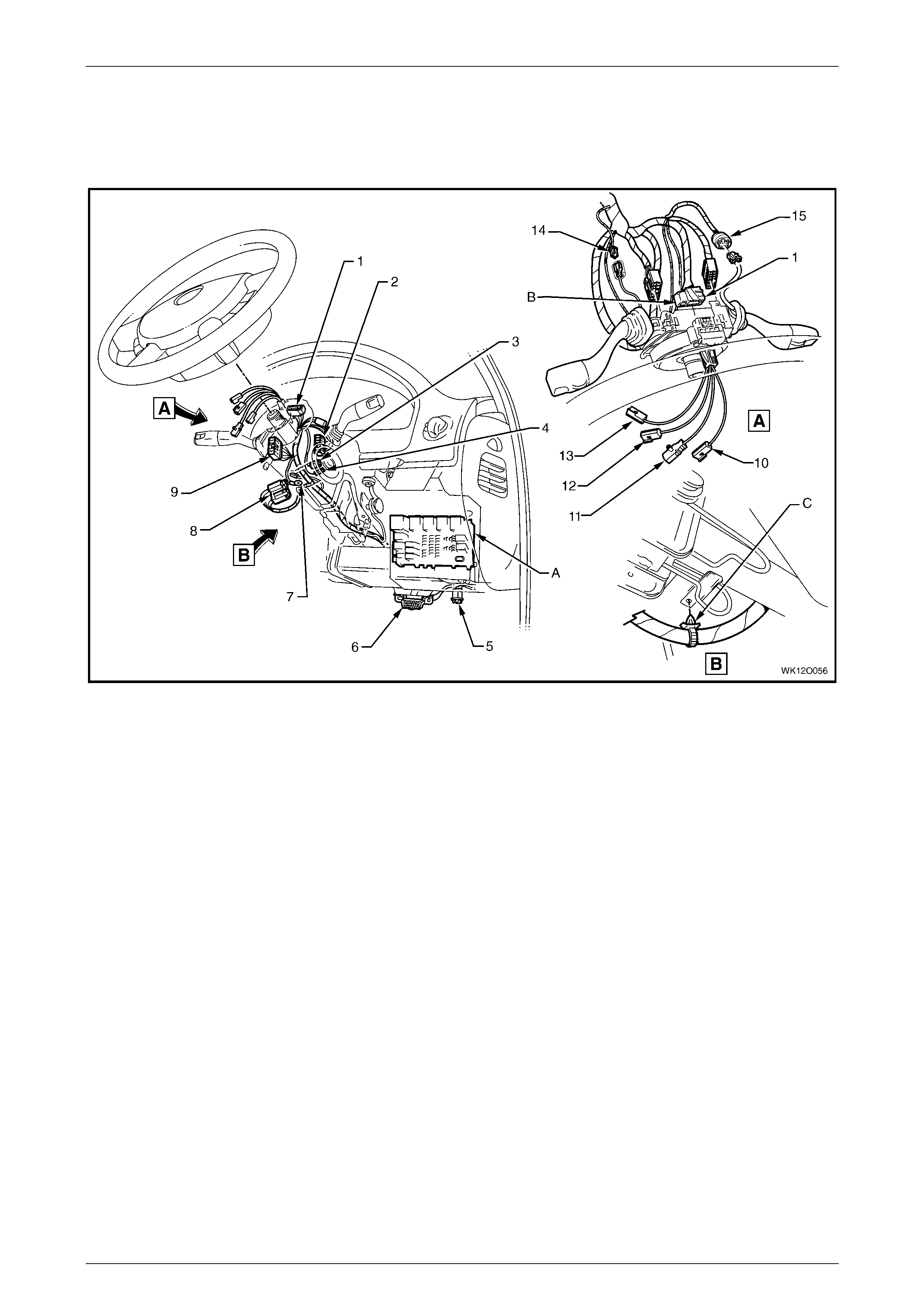
3.34 Main Wiring Harness – 13
Steerin g Column – RHD
Figure 12O – 52
Legend
1 Steering Wheel Clock Spring Coi l Connector (X116)
2 Turn Signal and Headlamp Switch Connector (S231)
3 Igniti on Lock Cylinder Bulb Connector (E30)
4 Igniti on and Start Switch Connect or (S149 – X2)
5 Stepwell Lamp Connect or (E 105)
6 Wiring (Diagnostic) Connector (X40)
7 Ignition Switc h Terminal (S149 – GP15 – X3)
8 Ignition & Start Switch Connector (S149 – X1)
9 Windshiel d Wiper & Washer Switch Connector (S247)
10 Steering Wheel Horn Connector (S7)
11 Steering Wheel Inflator Restraint Module Connector (A106)
12 Radio Control S witch Connect or (S208 – X2)
13 Radio Control S witch Connect or (S208 – X1)
14 Windshiel d Wiper Dwell Module Connect or (R23)
15 Cruise Control Switc h Connect or (S43)
A For fuse and relay panel – instrument panel wiring harnes s
fuse block (X129) inst al l ati on, ref er to 3.33 Main Wiring
Harness – 12.
B Clock s pri ng coil connecto r i nst al l ed and secured by l ocking
retainer in direction of arrow shown.
C Main wiring harness attached to steering column as shown.
Fuses, Relays and Wi ring Harnesse s Page 12O–59
Page 12O–59
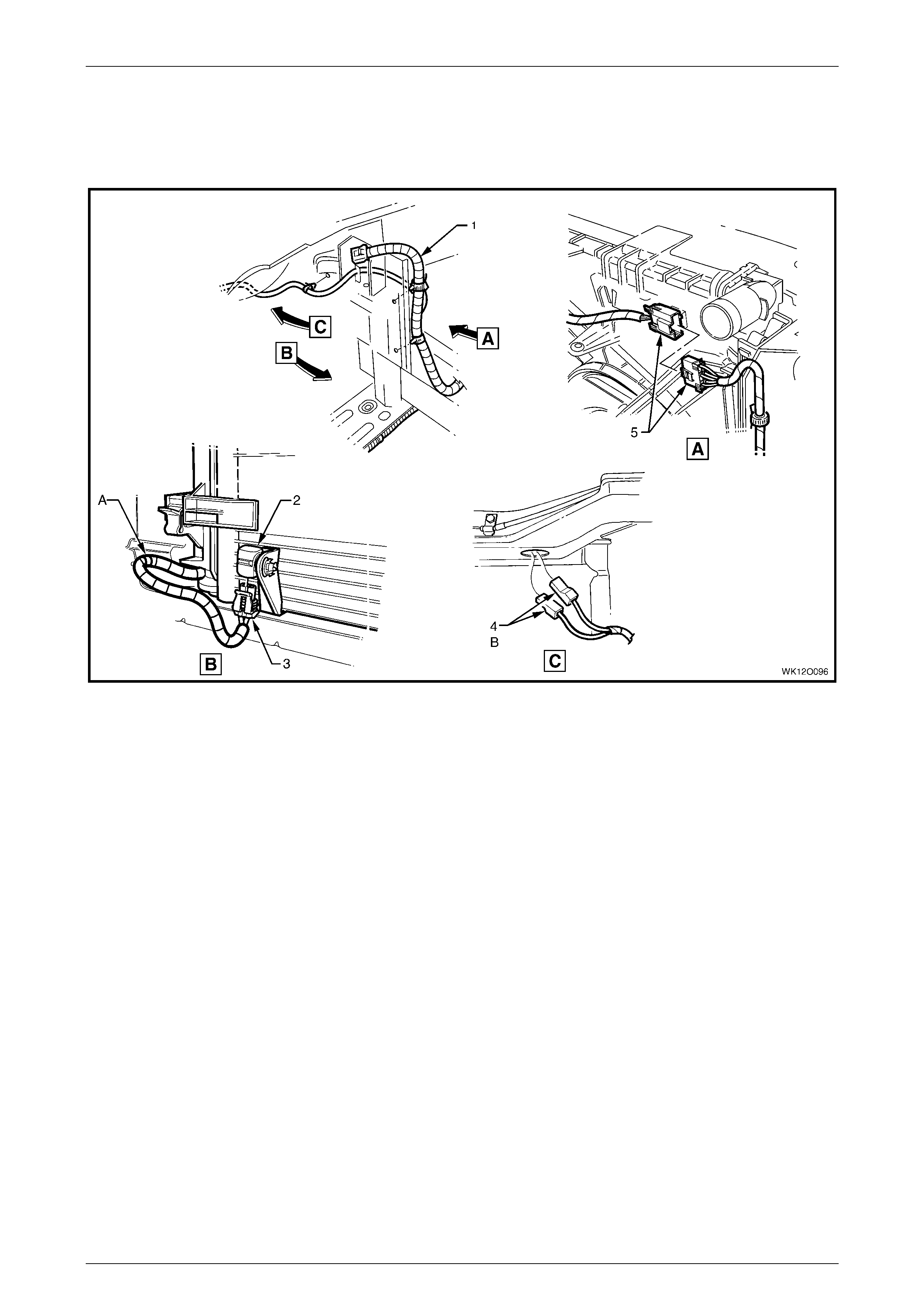
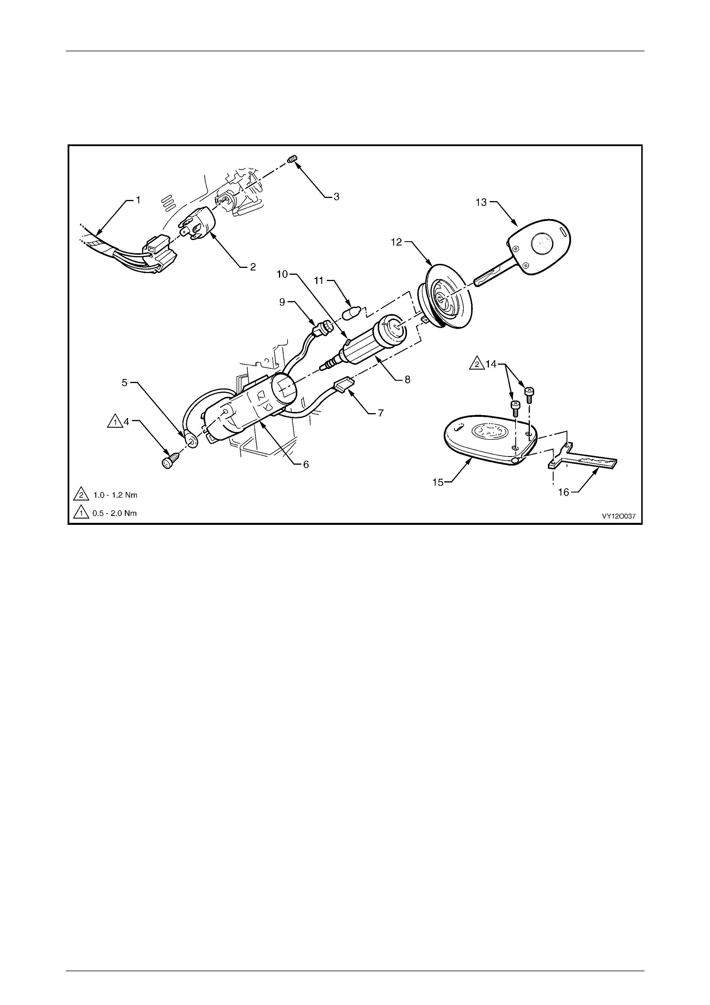
3.35 Main Wiring Harness – 14
Ignition Lock and Theft Deterrent Receiver
Figure 12O – 53
Legend
1 Main Wiring Harness
2 Ignition & Start Switch Connector (S149 – X1)
3 Ignition & Start Switch to Ignition Lock Retaining Screw
4 Earth Terminal to Ignition Key Attaching Screw
5 Ignition & Start Switch Terminal (S149 – X3)
6 Igniti on Lock Housi ng
7 Ignition & Start Switch Connector (S149 – X2)
8 Ignition Lock
9 Igniti on Lock Cyl i nder Bulb Connect or (E30)
10 Igniti on Lock Lock i ng Pin
11 Ignition Lock Cylinder Bulb
12 Theft Deterrent Receiver Assembly
13 Coded Key Assembly
14 Coded Key Assembly Attaching Screw
15 Remote Control Transmi tter
16 Key
Fuses, Relays and Wi ring Harnesse s Page 12O–60
Page 12O–60
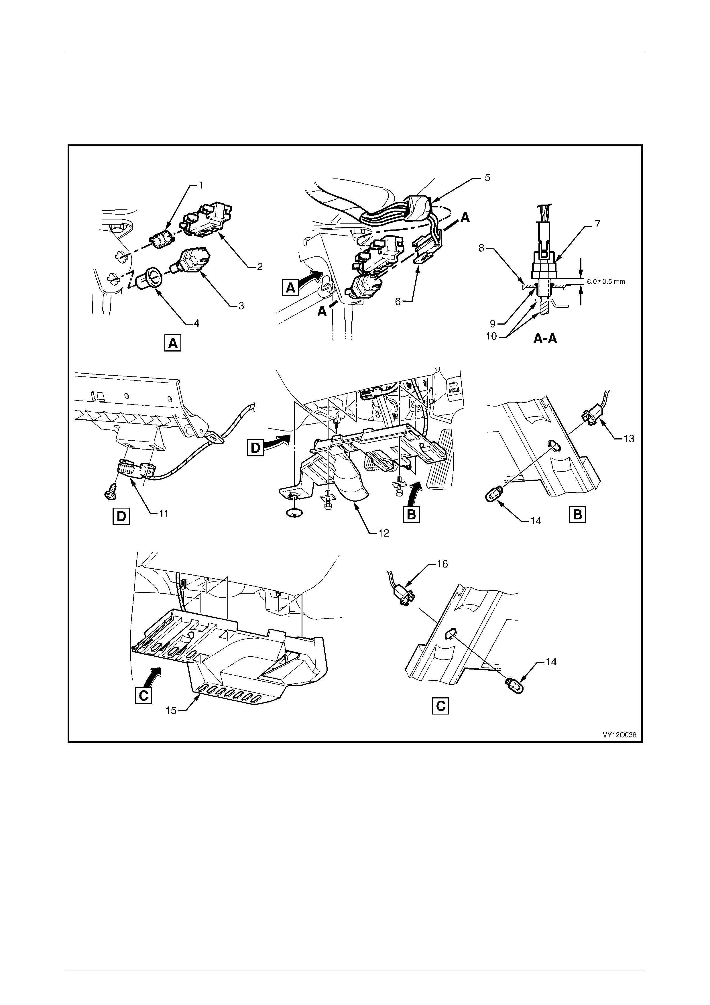
3.36 Main Wiring Harness – 15
Cruise Control, Stop Lamp Switches, Data Link Connector and Stepwell Lamps – RHD
Figure 12O – 54
Legend
1 Nut
2 Cruise Control Rel ease Switc h
3 Stepwell Lamp Switch
4 Nut
5 Stop Lamp, Traction & Cruise Control Releas e Switc h
Connector (S 220 – X2)
6 Stop Lamp, Traction & Cruise Control Releas e Switc h
Connector (S 220 – X1)
7 Stop Lamp Switch
8 Support Bracket
9 Nut
10 Pedal Assembly
11 Wiring (Diagnostic) Connector (X40)
12 Instrument P anel Lower Cover – Right-hand S ide
13 Stepwell Lamp Connect or (E105 – R)
14 Stepwell Lamp
15 Instrument P anel Lower Cover – Left-hand Side
16 Stepwell Lamp Connect or (E 105 – L)
Fuses, Relays and Wi ring Harnesse s Page 12O–61
Page 12O–61
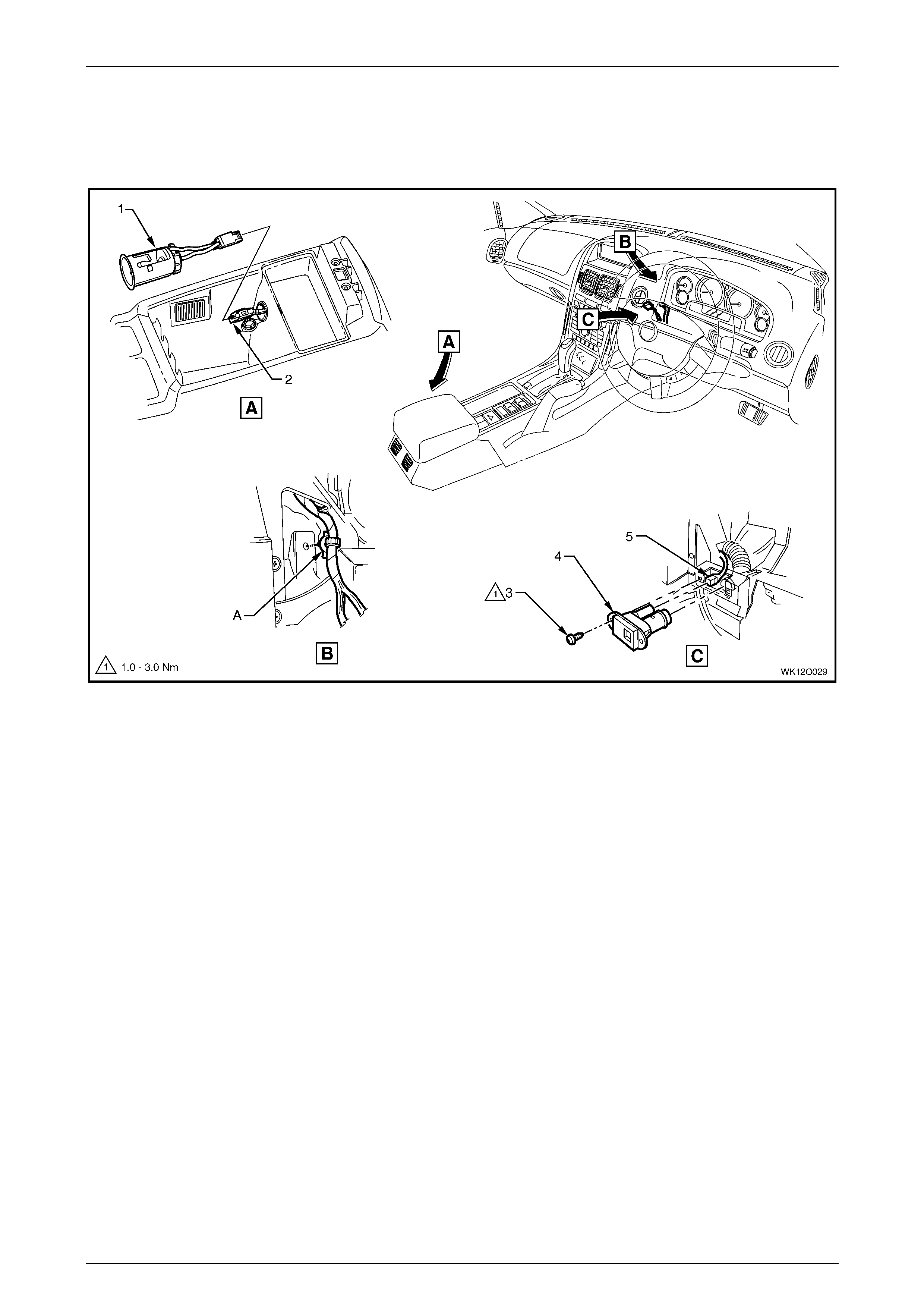
3.37 Main Wiring Harness – 16
Inside Air Temperature Sensor & Accessory Jack – RHD
Figure 12O – 55
Legend
1 Accessory Power Socket
2 Access ory P ower Connector (X112)
3 Inside Air Temperature Sensor Attaching Screw
4 Inside Air Temperature Sensor
5 Inside Air Temperature Sensor Connect or (B59)
A W iring harness attached to instrument panel as shown.
Fuses, Relays and Wi ring Harnesse s Page 12O–62
Page 12O–62
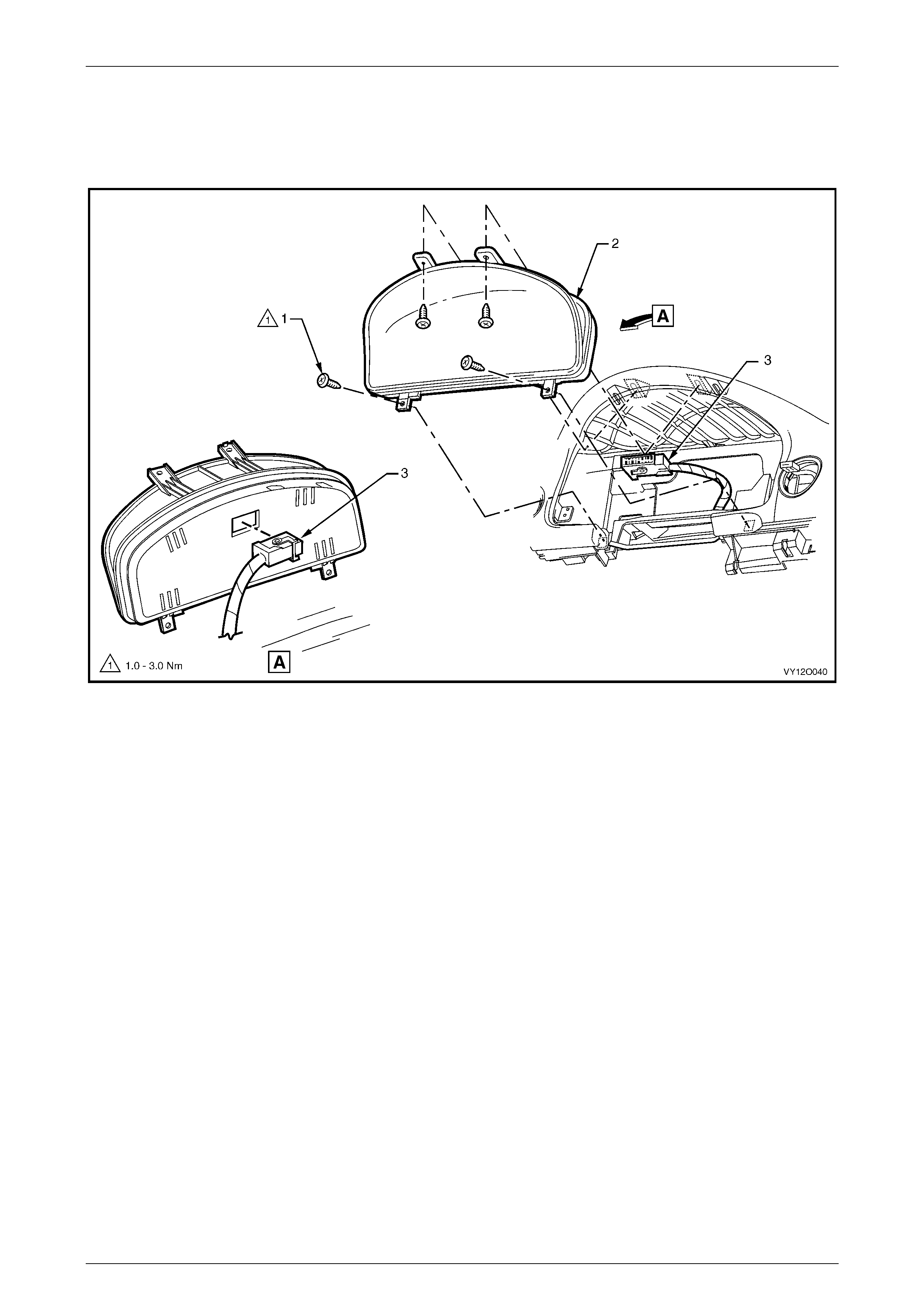
3.38 Main Wiring Harness – 17
Instrument Cluster Ass embly
Figure 12O – 56
Legend
1 Instrument Cl ust e r Attaching Screws (4 Plac es)
2 Instrum ent Cluster Assembly 3 Instrument Cl ust e r Connector (P3)
Fuses, Relays and Wi ring Harnesse s Page 12O–63
Page 12O–63
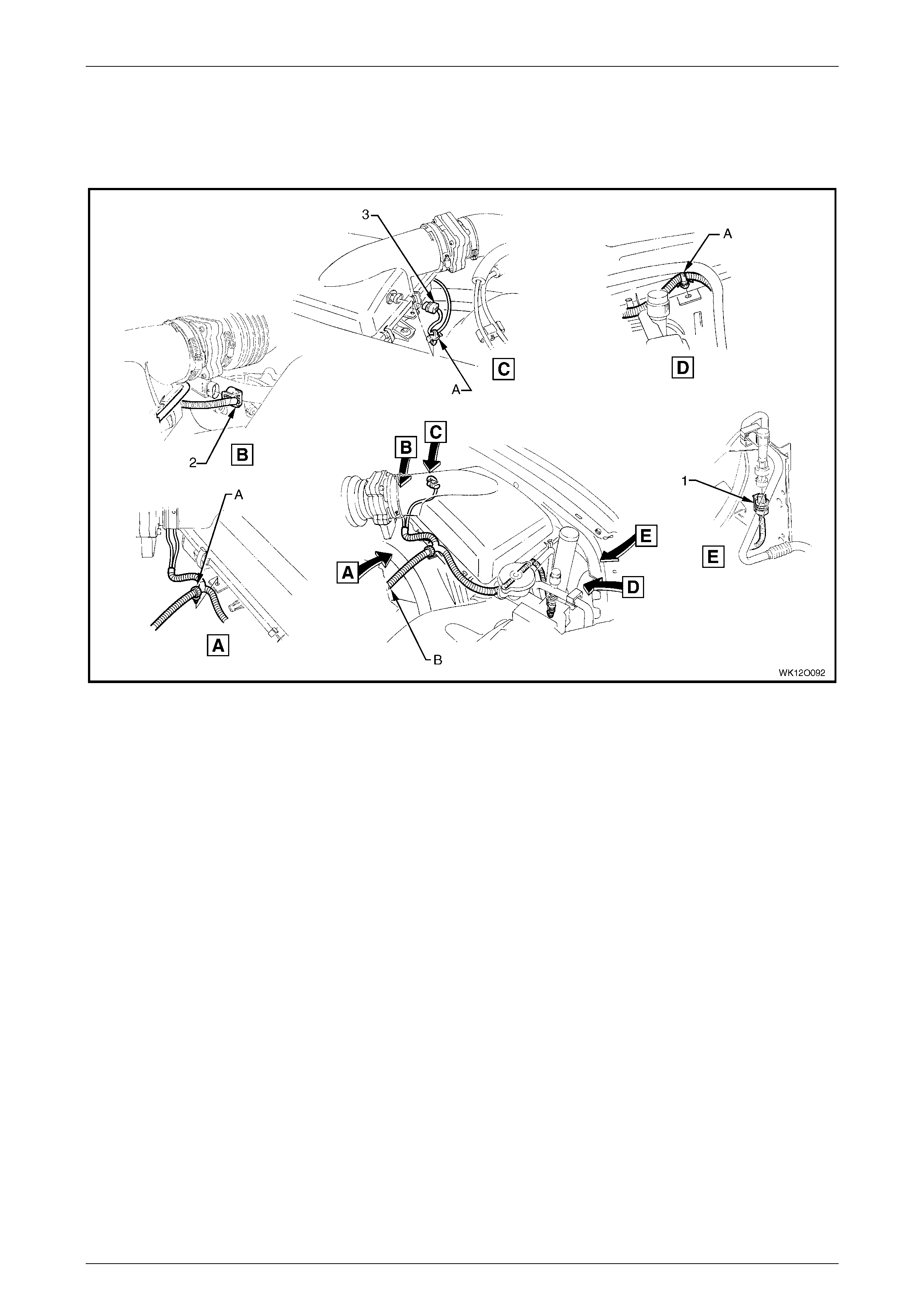
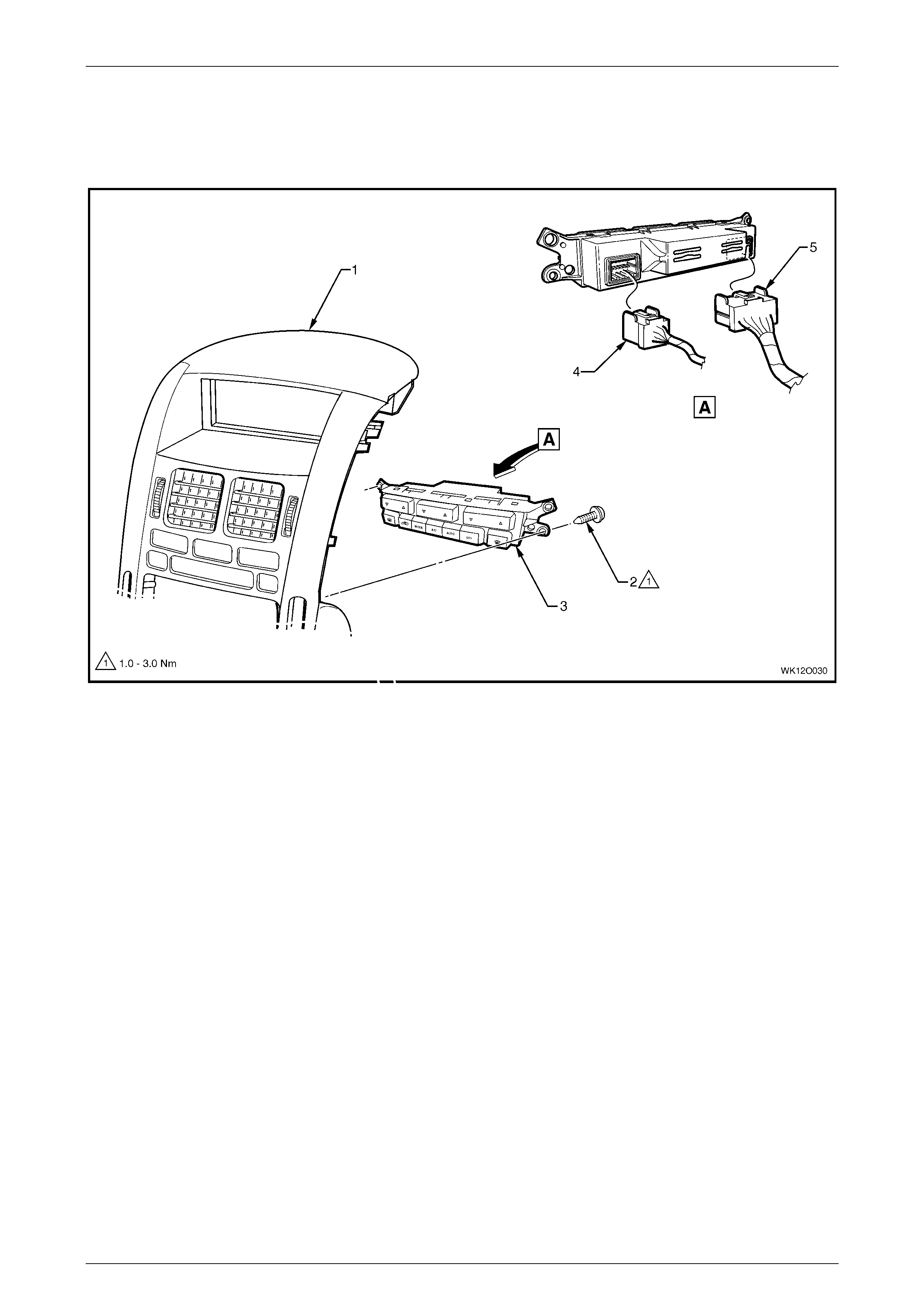
3.39 Main Wiring Harness – 18
Air-condit i oning and Heating Controls
Figure 12O – 57
Legend
1 Centre Fascia Escutcheon Assembly
2 Attachi ng Screws (4 Places )
3 Electroni c Cl imate Control Module
4 Blower Motor & A/C Compress or Connector (A14 – X1)
5 Blower Motor & A/C Compress or Connector (A14 – X2)
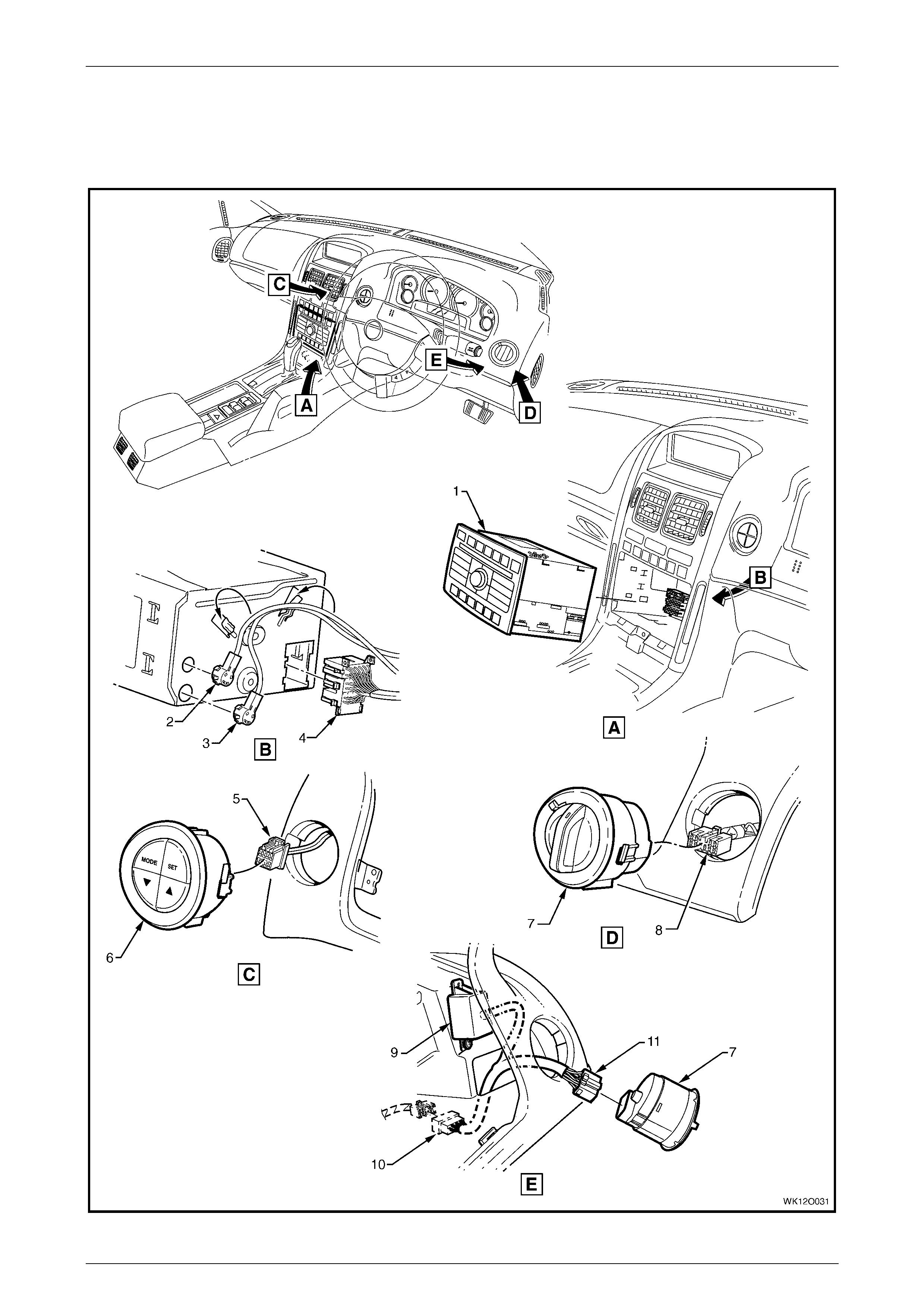
Fuses, Relays and Wi ring Harnesse s Page 12O–64
Page 12O–64
3.40 Main Wiring Harness – 19
Radio Assembly and Instrument Panel Facia Trim Switches and Connectors – RHD
Figure 12O – 58

Fuses, Relays and Wi ring Harnesse s Page 12O–65
Page 12O–65
Legend
1 Radio, Clock and CD Player As sembly
2 Diversit y Antenna Connector (A133 – X3)
3 Power Antenna Connect or (A133 – X2)
4 Radio, Clock and CD Player As sembly
Connector (A 133 – X1)
5 Trip Odometer Reset Switch Connector (S237)
6 Trip Odometer Reset Switch
7 Headlamp Automatic Control Switch
8 Headlamp Automatic Control Switch Connect or (S125)
9 Daytime Running Lamp Control Module
10 Daytime Running Lam p Control Module
Connector (A 25 – X1)
11 Daytime Running Lam p Control Module Connect or
(A25 – X2)
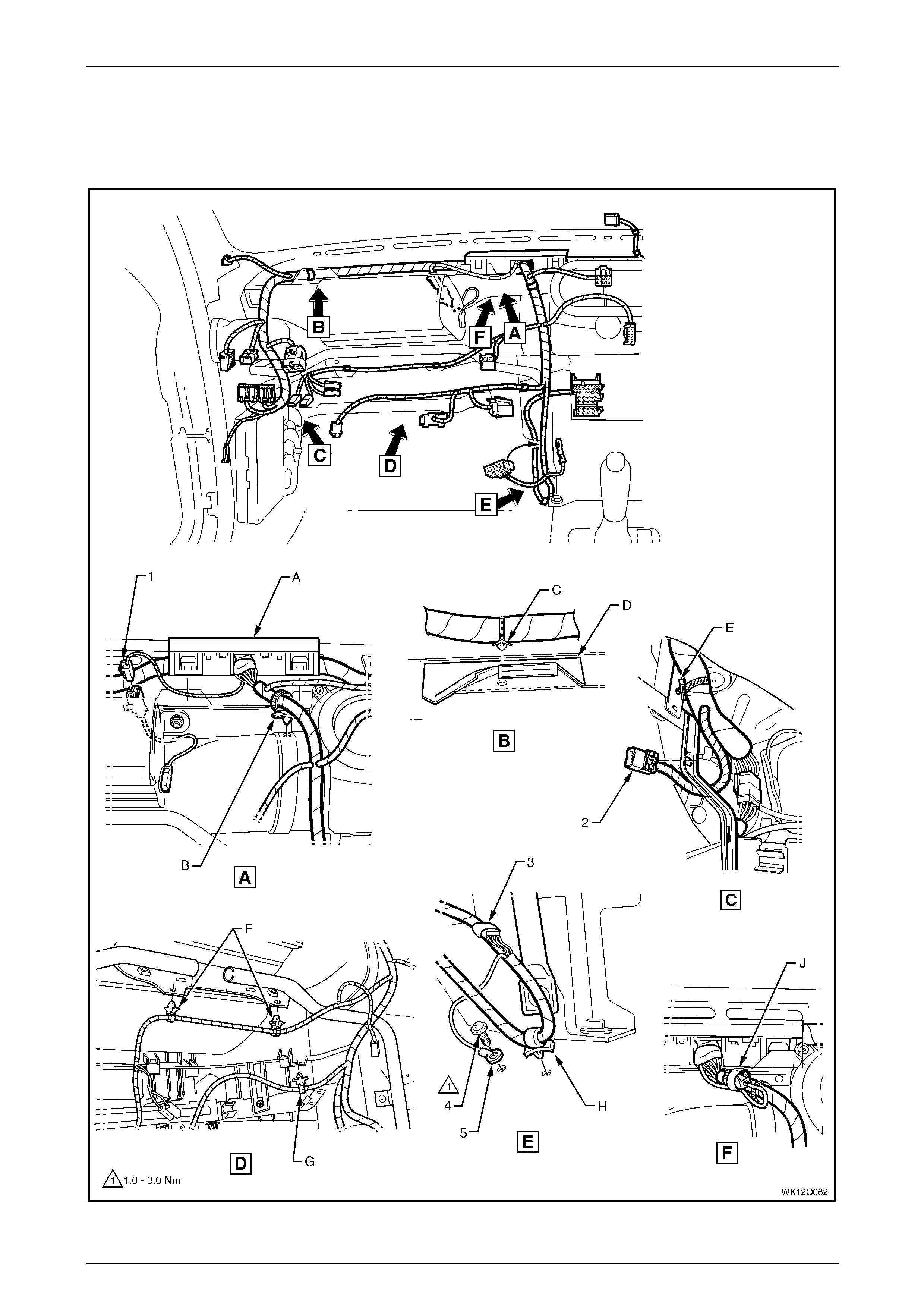
Fuses, Relays and Wi ring Harnesse s Page 12O–66
Page 12O–66
3.41 Main Wiring Harness – 20
Passenger Side Airbag Wiring – RHD
Figure 12O – 59

Fuses, Relays and Wi ring Harnesse s Page 12O–67
Page 12O–67
Legend
1 Main Wiring Harness To Passenger Air bag Harness
Connector (X205)
2 Main Wiring Harness t o Global Positioning S yst em
Harness Connect or (X207)
3 Inline to Radio and Mobile Telephone Connector (X155)
4 Radio Ground Terminal Attaching Screw
5 Radio Ground Terminal (X118 – GP8)
A Harness former att ached t o inst rum ent panel cover
assembly as shown (2 places).
B Harness attached t o heating, vent ilation & air conditioning
unit as shown.
C Harness attached to dash panel cover assembly as shown.
D Dash panel cover assembly.
E Harness attached to bracket as shown.
F Harness attached t o passenger side airbag support rail
assembly as shown.
G Harness attached to vehic l e as shown.
H Harness attached to vehicle as shown.
J Instrument panel i nfl atable restraint modul e connect or taped
back as shown (vehicl es without instrument panel inf l atable
restraint module).
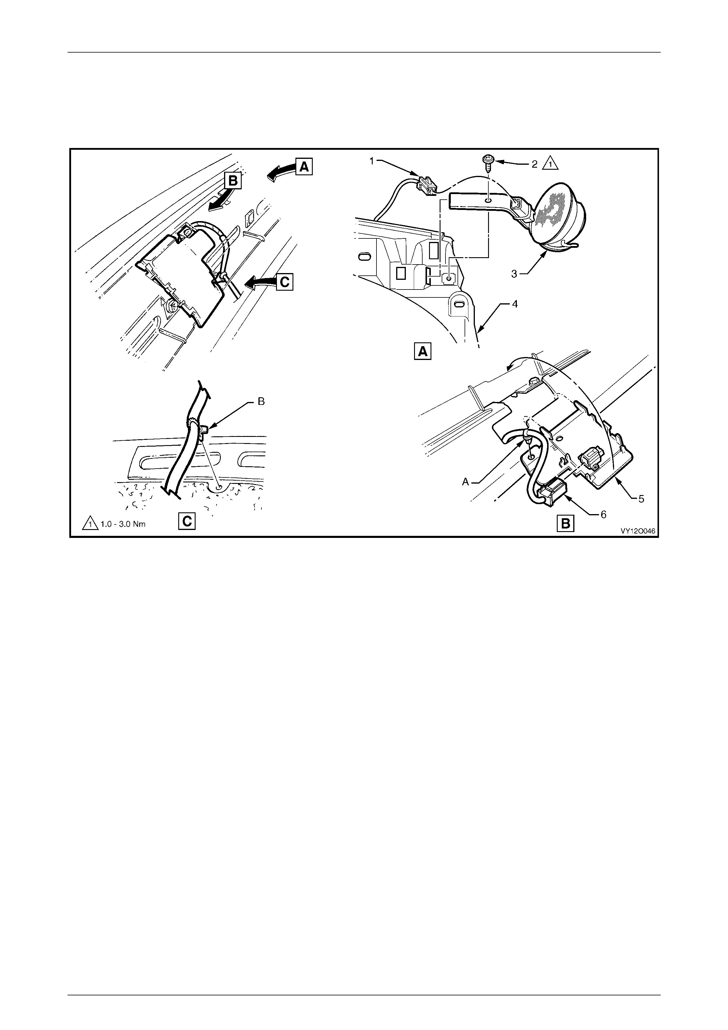
Fuses, Relays and Wi ring Harnesse s Page 12O–68
Page 12O–68
3.42 Main Wiring Harness – 21
Light Sensor & Key Receiver and Instrument Panel Speaker
Figure 12O – 60
Legend
1 Radio Front Speaker Dash Upper Connector (B 112)
2 Attaching Screw
3 Radio Front Speaker Dash Upper
4 Carrier Instrument Panel Pad
5 Ambient Light Sensor
6 Ambient Light Sensor Connect or (B55)
A Harness attached to light sensor and key receiver module as
shown.
B Instrument panel front speaker bracket aligned with locating
pin.
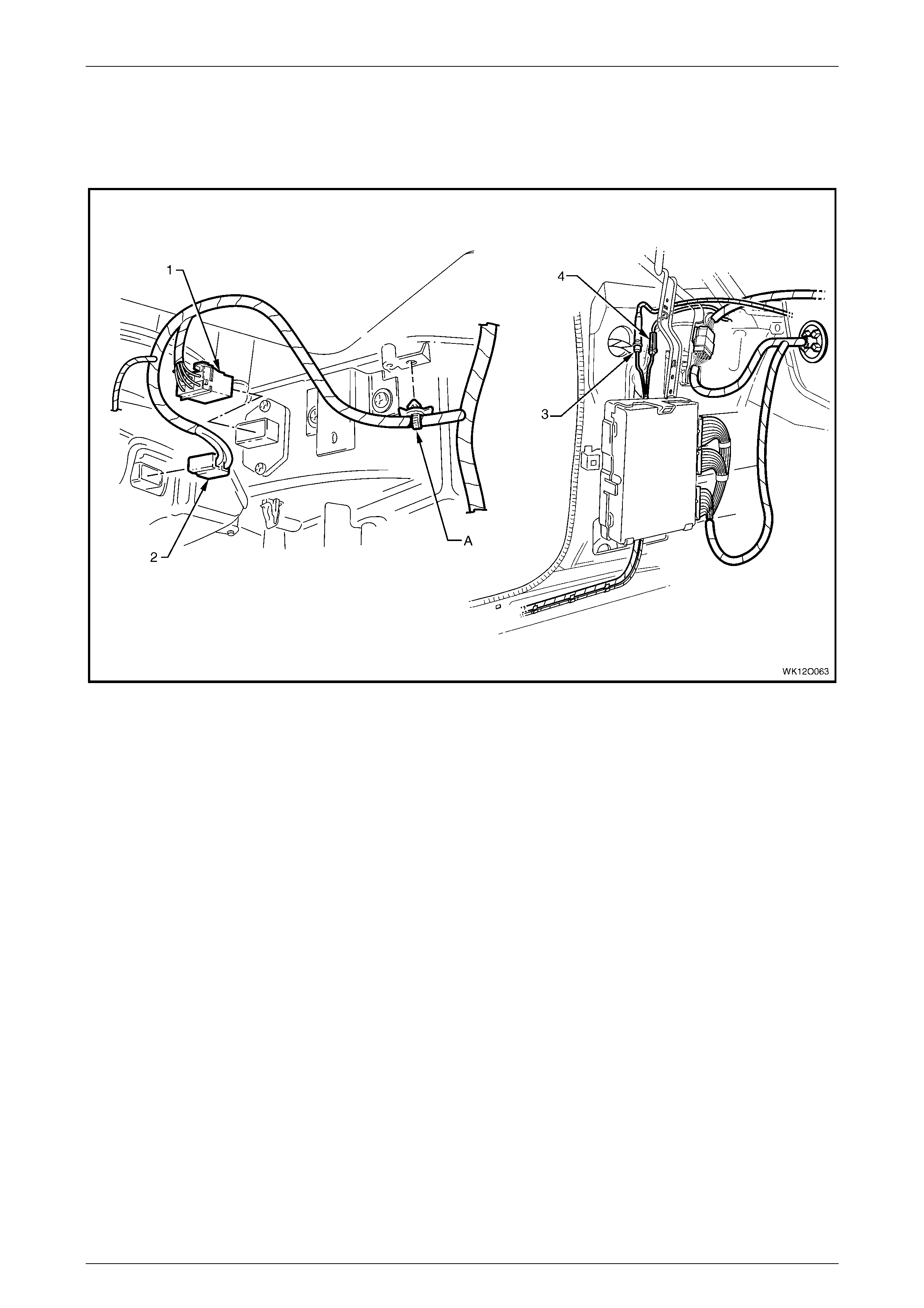
Fuses, Relays and Wi ring Harnesse s Page 12O–69
Page 12O–69
3.43 Main Wiring Harness – 22
Radio Antenna Amplifier and Heating, Ventilation & Air-conditioner Connectors – RHD
Figure 12O – 61
Legend
1 Blower Motor Resist or Connector (R6 – RHD)
2 Blower Motor Connector (M3 – RHD)
3 Radio Antenna Connect or (W6)
4 Radio Antenna Amplif i er Connect or (N3)
A Harness attached to body as shown.
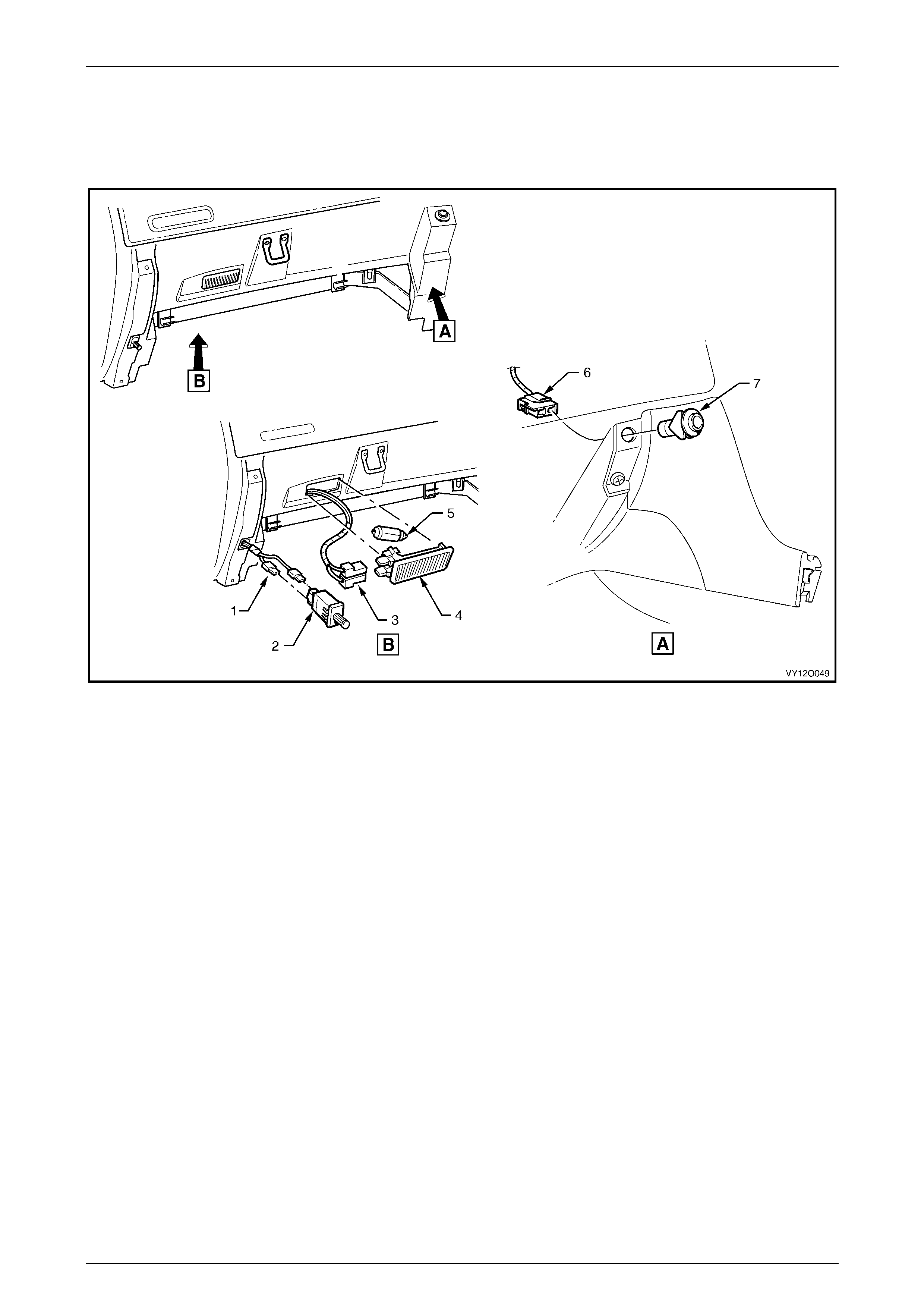
Fuses, Relays and Wi ring Harnesse s Page 12O–70
Page 12O–70
3.44 Main Wiring Harness – 23
Instr ument Panel Compartment – RHD
Figure 12O – 62
Legend
1 Instrument P anel Compartment Lamp Switch Connectors
(S142)
2 Instrument P anel Compartment Lamp Switch
3 Instrument P anel Compartment Lamp Connectors (E82)
4 Instrument P anel Compartment Lamp
5 Instrument P anel Compartment Lamp Bulb
6 Rear Compartment Lid Release Switc h Connector (S195)
7 Rear Compartment Lid Release Switc h
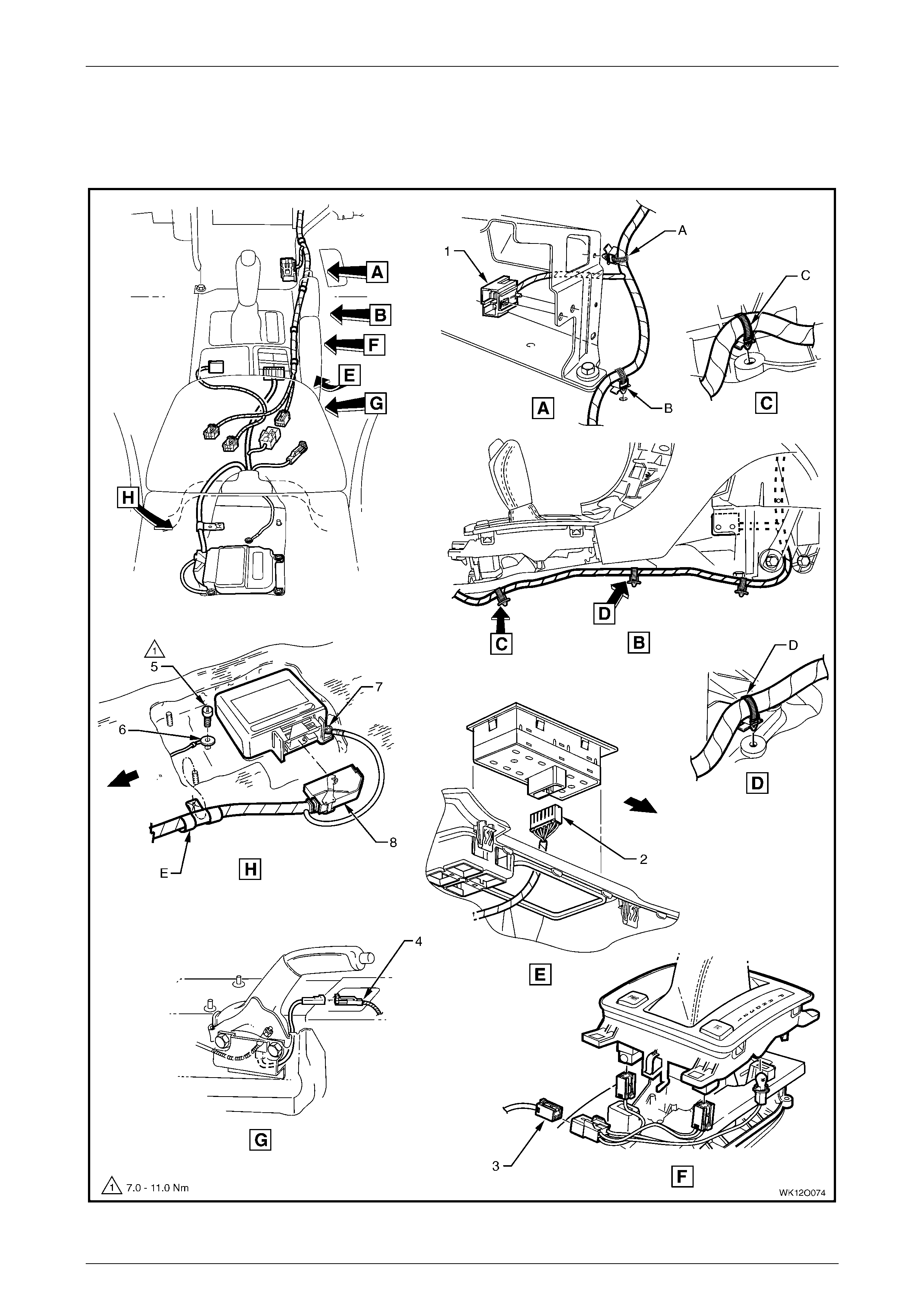
Fuses, Relays and Wi ring Harnesse s Page 12O–71
Page 12O–71
3.45 Main Wiring Harness – 24
Transmission and SIR Sensing Diagnostic Module Connectors – RHD
Figure 12O – 63

Fuses, Relays and Wi ring Harnesse s Page 12O–72
Page 12O–72
Legend
1 Front Cigar Lighter Connect or (X113 – F)
2 Side Window (Master) Switch Connector (S222)
3 Main Wiring Harness to Transmission Select or Harness
Connector (X301)
4 Park Brake Switc h Connect or (S181)
5 Body Harness Earth Terminal Attaching Screw
6 Ground Terminal (X118 – GP12)
7 Ground Terminal (X118 – GP11)
8 Inflation Restraint Sensor Connector (A65)
A Harness attached t o lower radio brack et as shown.
B Harness attached to vehicle as shown.
C Main wiring harness att ached to tunnel as shown.
D Main wiring harness att ached to tunnel as shown.
E Harness attached to stud as shown.
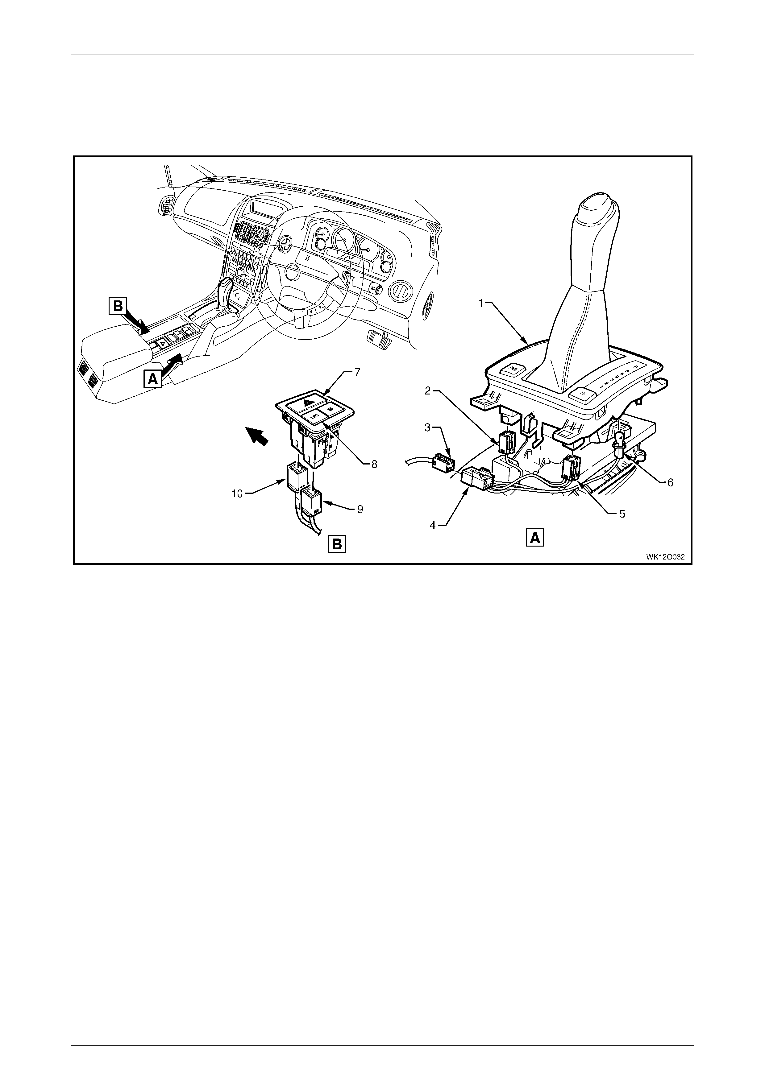
Fuses, Relays and Wi ring Harnesse s Page 12O–73
Page 12O–73
3.46 Main Wiring Harness – 25
Transmission Selector and Floor Console Connectors – RHD
Figure 12O – 64
Legend
1 PRNDL Select or Housi ng
2 Auto/Trans Shift Program Connector (S22)
3 Main Wiring Harness to Transmission Select or Harness
Connector (X301)
4 Transmission Selector Harness to Main Wiring Harness
Connector (X301)
5 Electroni c Tract i on Control S witch Connect or (S73)
6 Auto/Trans Control P ositi on Indicator Lamp Connector
(E125)
7 Hazard Warning Switch
8 LPG Switch
9 LPG Switch Connector (S 118)
10 Hazard Warning S witch Connector (S120)

Fuses, Relays and Wi ring Harnesse s Page 12O–74
Page 12O–74
3.47 Main Wiring Harness – 26
Stop Lamp, Traction and Cruise Control Release Connectors – RHD
Figure 12O – 65
Legend
1 Stop Lamp, Traction & Cruise Control Releas e Switc h
Connector (S 220 – X3)
2 Stop Lamp, Traction & Cruise Control Releas e Switc h
Connector (S 220 – X1)
3 Stop Lamp, Traction & Cruise Control Releas e Switc h
Connector (S 220 – X2)
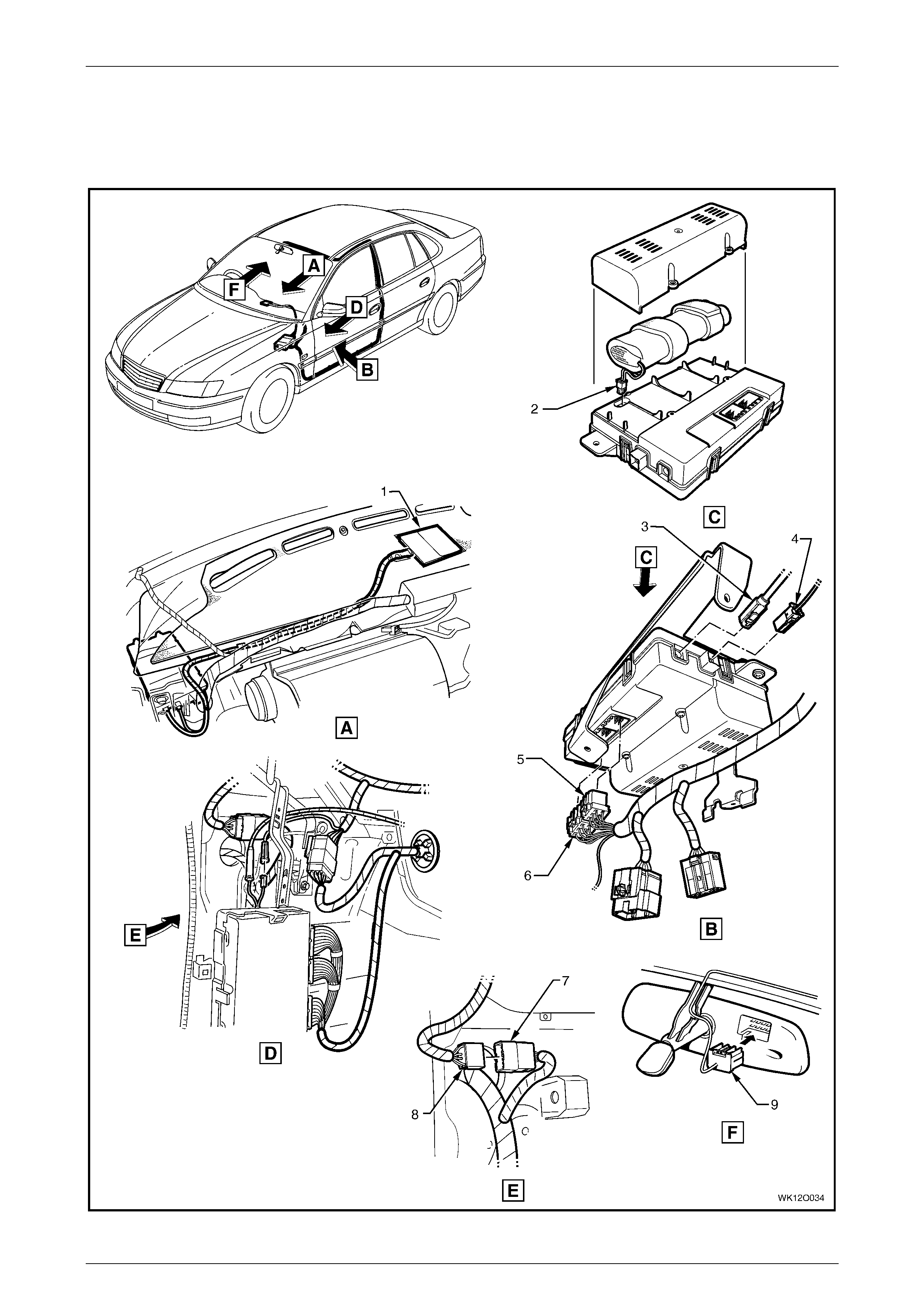
Fuses, Relays and Wi ring Harnesse s Page 12O–75
Page 12O–75
3.48 Main Wiring Harness – 27
Telematics System – RHD
Figure 12O – 66

Fuses, Relays and Wi ring Harnesse s Page 12O–76
Page 12O–76
Legend
1 Telematics System Antenna
2 Communic ation Centre Call Connector (A158 – X5)
3 Communic ation Centre Call Connector (A158 – X4)
4 Communic ation Centre Call Connector (A158 – X3)
5 Communic ation Centre Call Connector (A158 – X2)
6 Communic ation Centre Call Connector (A158 – X1)
7 Body Wiring Harness to Main Wiring Harness Connector
(X202)
8 Main Wiring Harness to Body Wiring Harness Connect or
(X202)
9 Inside Rearview Mirror Connector (E124 – B)
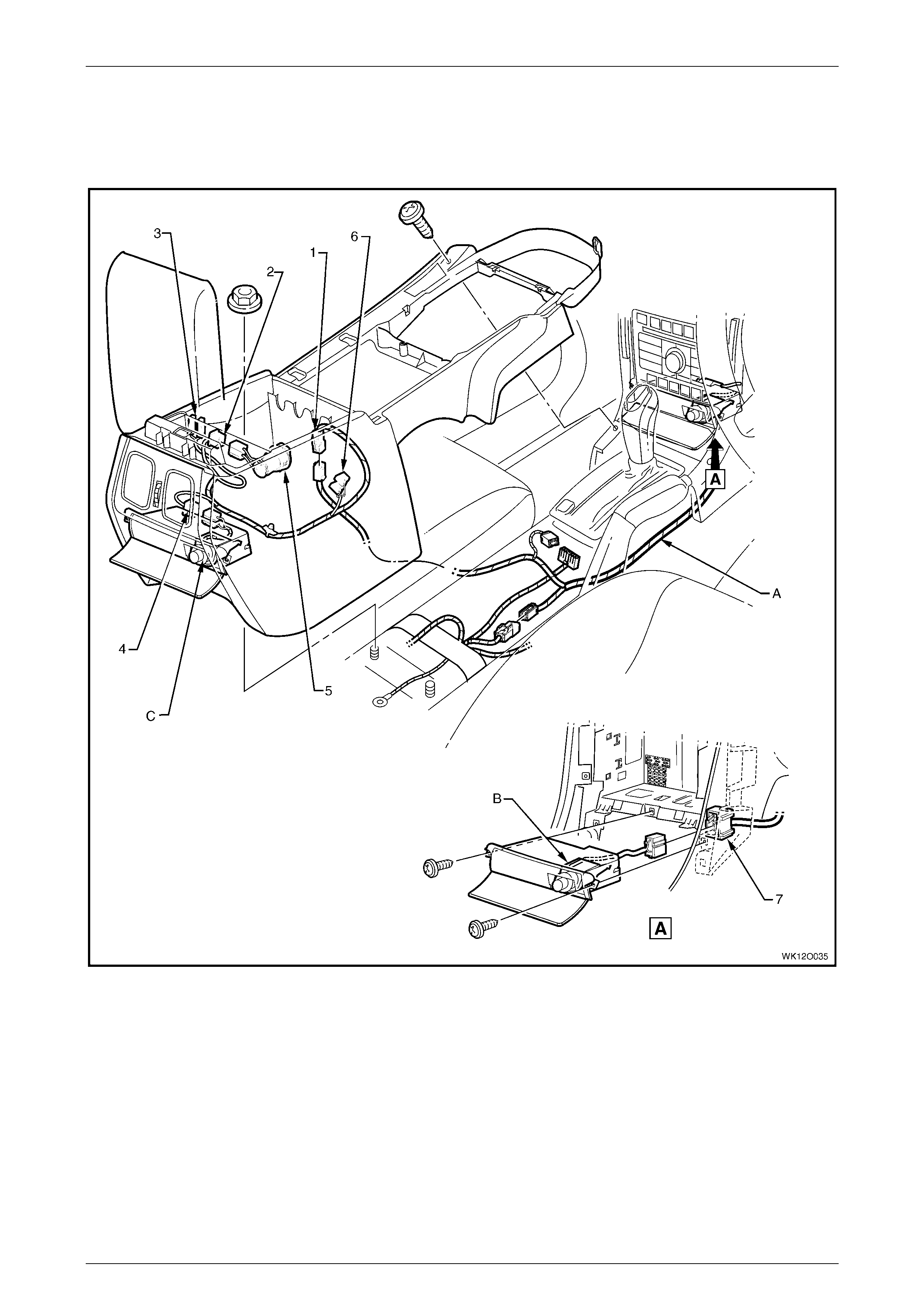
Fuses, Relays and Wi ring Harnesse s Page 12O–77
Page 12O–77
3.49 Main Wiring Harness – 28
Front and Rear Cigar Lighter and Accessory Power Connector
Figure 12O – 67
Legend
1 Console Wiri ng Harness t o Main Wiring Harness
Connector (X309)
2 Access ory P ower Connector (X112 – AUX)
3 Front Floor Console Compartment Lamp Switch
Connectors (S 94)
4 Rear Cigar Lighter Connec tor (X113 – R)
5 Accessory Power Jack
6 Front Floor Console Compartment Lamp Connectors (E16)
7 Front Cigar Lighter Connect or (X113 – F)
A Main wiring harness att ached to inside console (1 place).
B Front cigar lighter (if fitted).
C Rear cigar lig hter (if f itted).
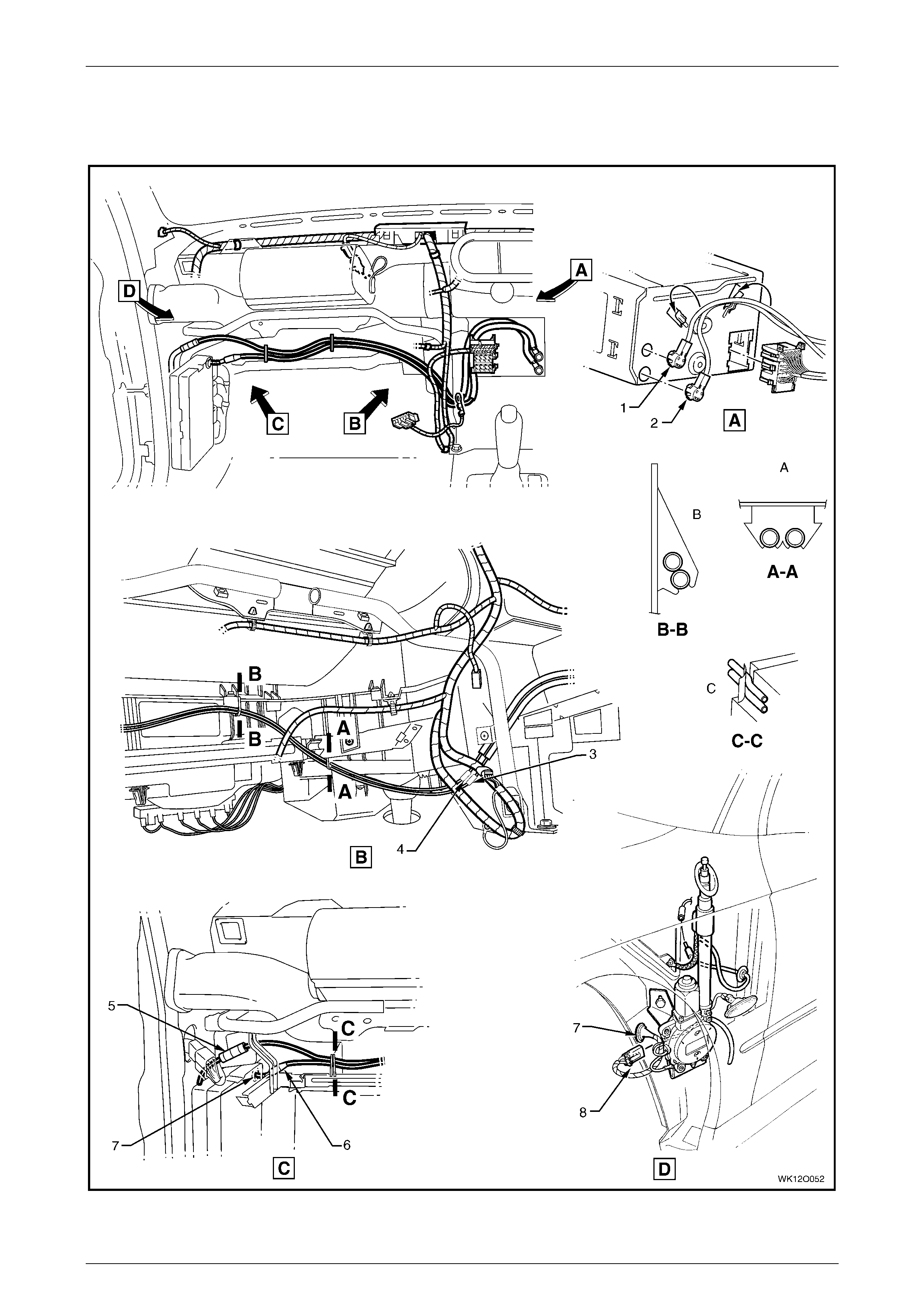
Fuses, Relays and Wi ring Harnesse s Page 12O–78
Page 12O–78
3.50 Radio Power Antenna Assembly Wiring –
RHD
Figure 12O – 68

Fuses, Relays and Wi ring Harnesse s Page 12O–79
Page 12O–79
Legend
1 Diversit y Antenna Connector (A133 – X3)
2 Power Antenna Connect or (A133 – X2)
3 In-line Diversity Antenna Connector (X208)
4 In-line Radio Ant enna Connector (X209)
5 Diversit y Antenna Lead Connector
6 Radio Power Antenna Connector (W6 – X2)
7 Antenna Lead Panel Blanking Grommet
8 Radio Power Antenna Connector (W6 – X1)
A Leads clipped t o underside of heating, vent i l ation and air
conditi oni ng assem bl y as shown.
B Leads clipped t o front side of heating, vent i l ation and air
conditi oni ng assem bl y as shown.
C Leads tucked behind rout i ng post on heating, vent i l ation and
air conditioning assembly as shown.
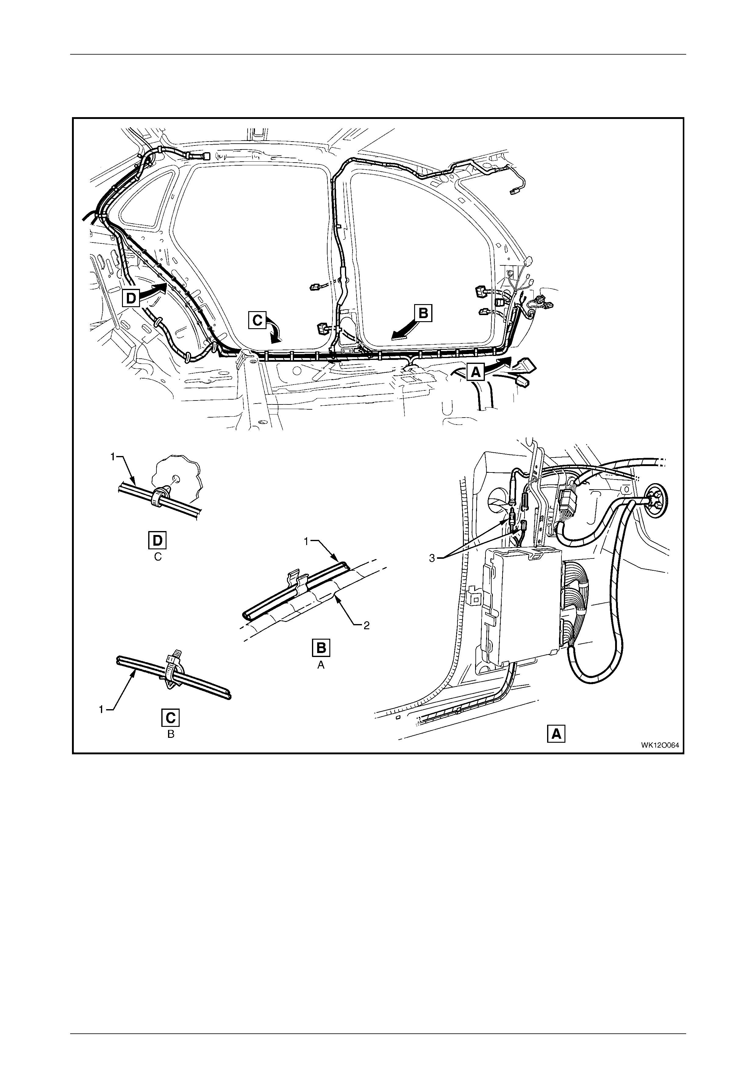
Fuses, Relays and Wi ring Harnesse s Page 12O–80
Page 12O–80
3.51 Radio Amplifier and Antenna Wiring – 1
Figure 12O – 69
Legend
1 Diversit y Antenna Lead
2 Body Wiring Harness
3 Amplifier Assem bl y Radio Antenna Leads
A Lead attached along sil l as shown.
B Lead attached along sil l as shown.
C Lead attached to body as shown.
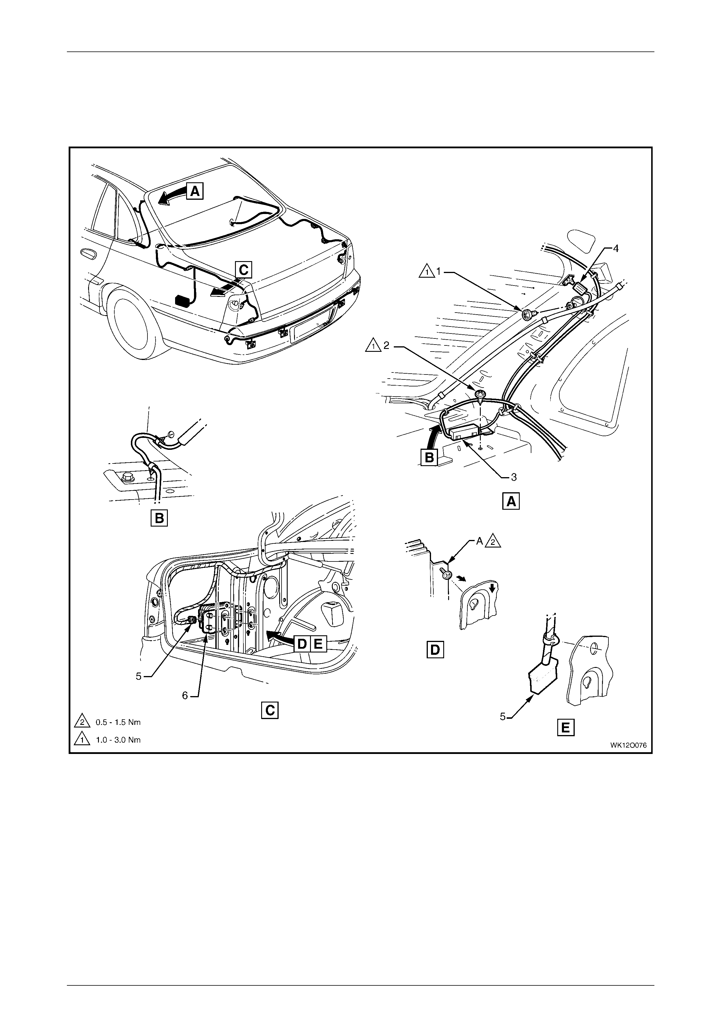
Fuses, Relays and Wi ring Harnesse s Page 12O–81
Page 12O–81
3.52 Radio Amplifier and Antenna Wiring – 2
Level 1, 2, 3 a nd 4
Figure 12O – 70
Legend
1 Attachi ng Screw Amplifier Assem bly Radio A ntenna
Earth To C Pillar
2 Attachi ng Screw Amplifier Assem bly Radio A ntenna
To Body
3 Radio Antenna Amplifier
4 Radio Antenna Connect or (W4)
5 Radio Rear Speaker Amplif i er Connect or (N6)
6 Radio Rear Speaker Amplifier
A Amplifier att aching screw positioned through hole (4 places).
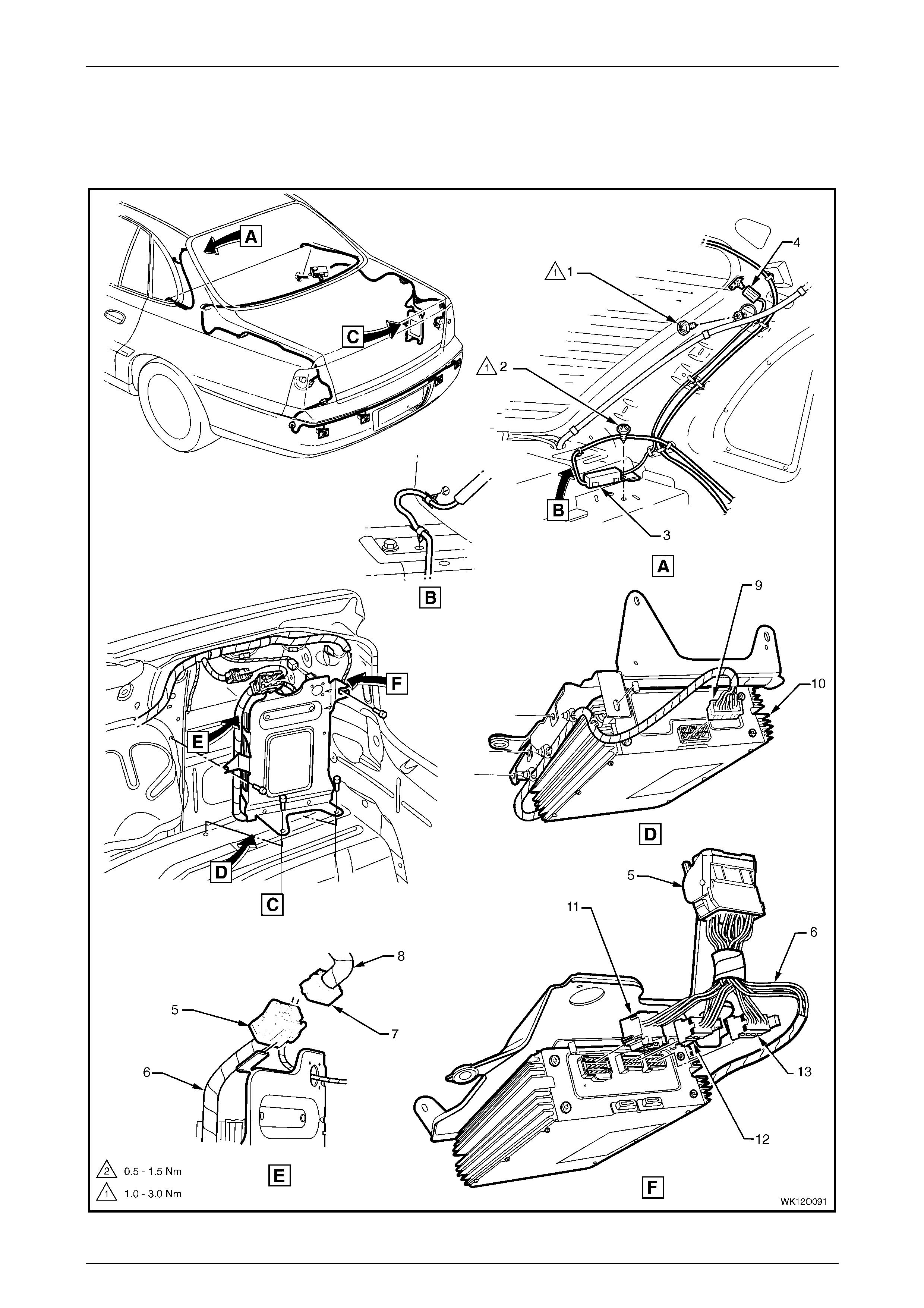
Fuses, Relays and Wi ring Harnesse s Page 12O–82
Page 12O–82
3.53 Radio Amplifier and Antenna Wiring – 3
Level 5
Figure 12O – 71

Fuses, Relays and Wi ring Harnesse s Page 12O–83
Page 12O–83
Legend
1 Attachi ng Screw Amplifier Assem bly Radio A ntenna
Earth To C Pillar
2 Attachi ng Screw Amplifier Assem bly Radio A ntenna
To Body
3 Radio Antenna Amplifier
4 Radio Antenna Connect or (W4)
5 Audio Patch Harness to Body Wiring Harness
Connector (X403)
6 Audio Patch Harness
7 Body Wiring Harness to Audio Patch Harness
Connector (X403)
8 Body Wiring Harness
9 Radio Rear Speaker Amplif i er Connect o r (N7 – X1)
10 Radio Rear Speaker Amplif i er
11 Radio Rear Speaker Amplif i er Connect o r (N7 – X3)
12 Radio Rear Speaker Amplif i er Connect o r (N7 – X2)
13 Radio Rear Speaker Amplif i er Connect o r (N7 – X4)
A Amplifier att aching screw positioned through hole (4 places).
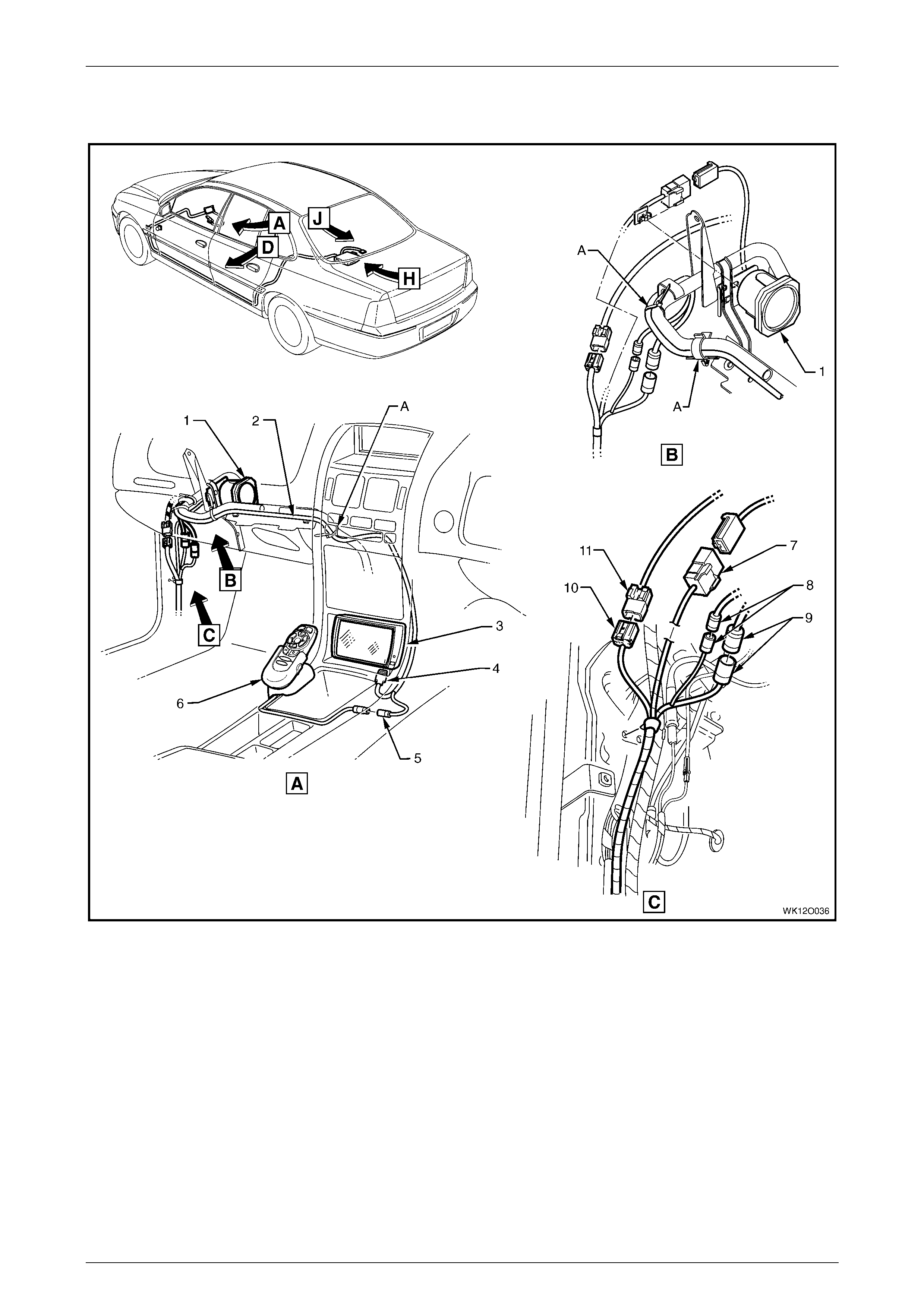
Fuses, Relays and Wi ring Harnesse s Page 12O–84
Page 12O–84
3.54 Navigation System Assembly – 1 – RHD
Figure 12O – 72
Legend
1 Speaker Assembly
2 Global Positioning System Harness
3 Display Assembly
4 Driver Inform ation Display Connector (P6)
5 Driver Inform at i on Dis pl ay Control Connect or (A35)
6 Remote Control Cradle
7 Navigation S peaker Assembly Connector (B104)
8 Global Positioni ng System Harness Connectors (XO2)
9 Global Positioni ng System Harness Connectors (XO1)
10 Global Positioni ng System Harness to Main Wiring Harness
Connector (X207)
11 Main Wiring Harness t o Global Positioning System Harness
Connector (X207)
A Harness attached t o passenger side airbag s upport rail
assembly as shown.
For views D, H & J, refer to
3.55 Navigati on System Assembly – 2 – RHD.
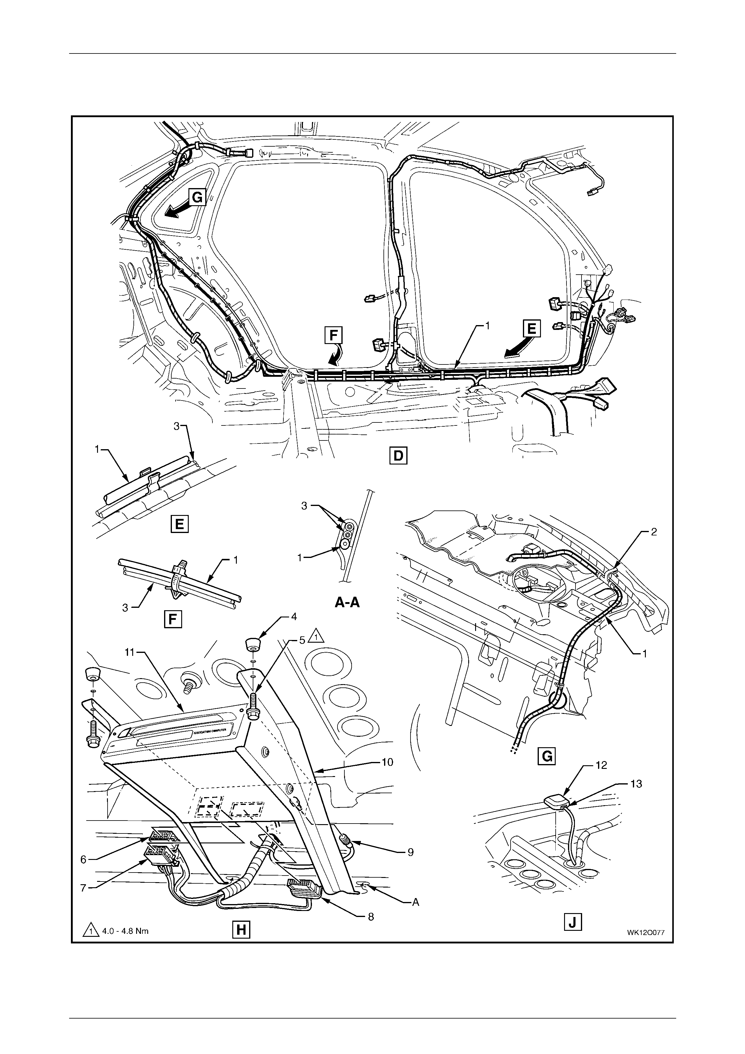
Fuses, Relays and Wi ring Harnesse s Page 12O–85
Page 12O–85
3.55 Navigation System Assembly – 2 – RHD
Figure 12O – 73

Fuses, Relays and Wi ring Harnesse s Page 12O–86
Page 12O–86
Legend
1 Global Positioning System Harness
2 Global Positioni ng System Harness Vehicle Attachi ng Clip
3 Diversit y Antenna Lead
4 Processor Assembly Mounting Points
5 Processor Assembly Mounting Screws
6 Navigation Cont rol Proc essor Connector (A139 – X2)
7 Navigation Cont rol Proc essor Connector (A139 – X1)
8 Navigation Cont rol Proc essor Connector (A139 – X3)
9 Navigation Cont rol Proc essor Connector (A139 – X4)
10 Processor Assembly Mounting Brackets
11 Navigation Control Processor Assembly
12 Antenna
13 Antenna Connector (W2 – GPS – 2)
A Process or assembl y brack et mounti ng hol es.
For location of views D, H & J, refer to
3.54 Navigati on System Assembly – 1 – RHD.
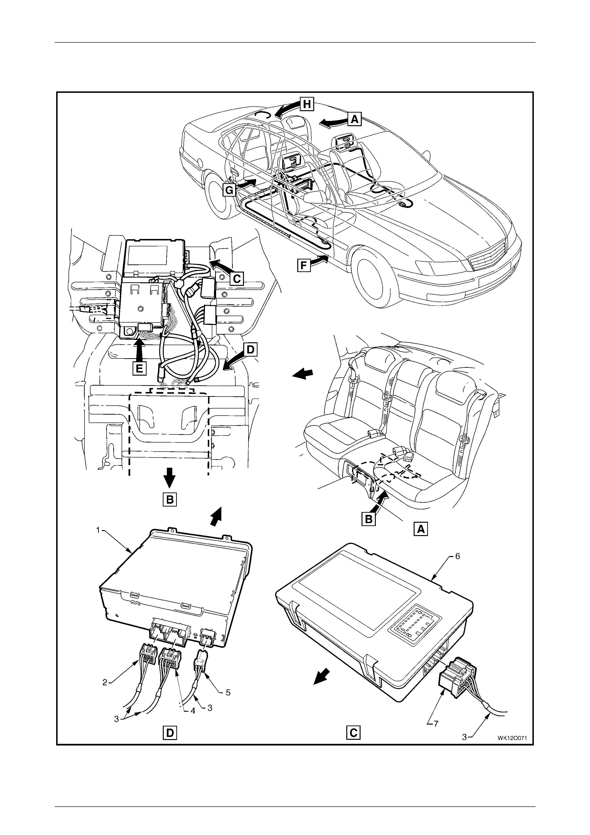
Fuses, Relays and Wi ring Harnesse s Page 12O–87
Page 12O–87
3.56 Video Player System and Wiring – 1
Figure 12O – 74

Fuses, Relays and Wi ring Harnesse s Page 12O–88
Page 12O–88
Legend
1 Video Player Ass embly
2 Video Player Ass embly Connect or (A152 – X2)
3 DVD Harness
4 Video Player Ass embly Connect or (A152 – X1)
5 Video Player Ass embly Connect or (A152 – X3)
6 Communication Interface Module
7 Communication Interface Module Connector (A156)
For views E, F, G & H, refer to
3.57 Video Player System and Wiring – 2.
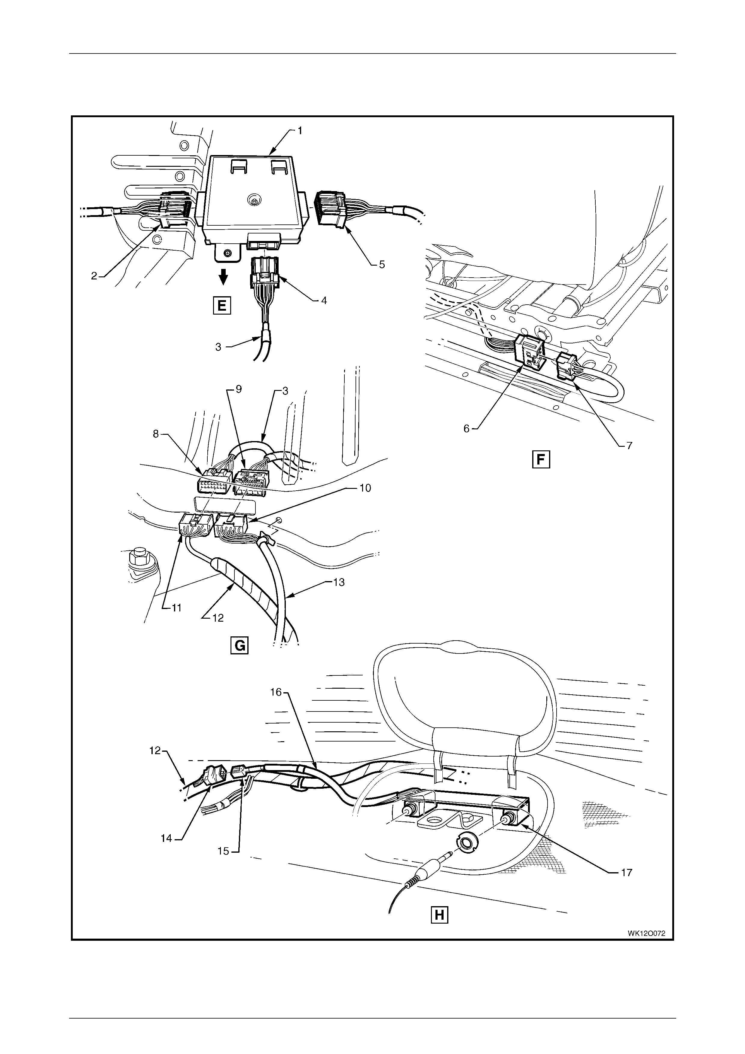
Fuses, Relays and Wi ring Harnesse s Page 12O–89
Page 12O–89
3.57 Video Player System and Wiring – 2
Figure 12O – 75

Fuses, Relays and Wi ring Harnesse s Page 12O–90
Page 12O–90
Legend
1 DVD Signal Splitter
2 DVD Signal Splitter Connector (A95 – X2)
3 DVD Harness
4 DVD Signal Splitter Connector (A95 – X1)
5 DVD Signal Splitter Connector (A95 – X3)
6 Seat-back Harness to DVD Harness Connect or (X319)
7 DVD Harness t o Seat-back Harness Connector (X319)
8 DVD Harness t o Body Wiring Harnes s Connector (X317)
9 DVD Harness t o Body Wiring Harnes s Connector (X318)
10 Seat-back Harness to DVD Harness Connect or (X318)
11 Body Wiring Harness to DVD Harness Connector (X317)
12 Body Wiring Harness
13 Seat-back Harness
14 Body Wiring Harness to Headphone Harness Connec tor
(X404)
15 Headphone Harness t o Body Wiring Harness Connector
(X404)
16 Headphone Harness
17 Headphone Control Connector (A164) - 2 Places
For location of views E, F, G & H, r efer to
3.56 Video Player System and Wiring – 1.
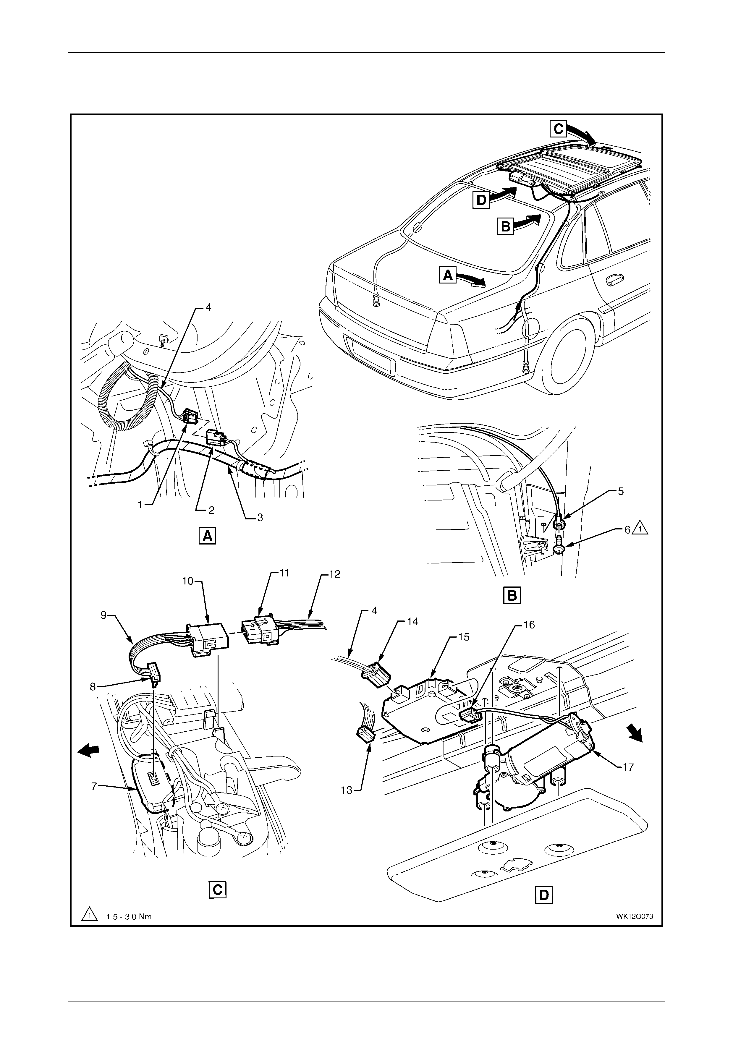
Fuses, Relays and Wi ring Harnesse s Page 12O–91
Page 12O–91
3.58 Sunroof System and Wiring
Figure 12O – 76

Fuses, Relays and Wi ring Harnesse s Page 12O–92
Page 12O–92
Legend
1 Sunroof Power Harness t o Body Wiring Harness
Connector (X322)
2 Body Wiring Harness to Sunroof Power Harness
Connector (X322)
3 Body Wiring Harness
4 Sunroof Power Harness
5 Sunroof Control Module Ground Termi nal (X118 – GP16)
6 Sunroof Control Module Ground Termi nal
Attach in g Screw
7 Sunroof Switch Assembly
8 Sunroof Switch Connect or (S228)
9 Sunroof Control Harnes s
10 Sunroof Control Harnes s to Sunroof Harness
Connector (X321)
11 Sunroof Harness to Sunroof Control Harness
Connector (X321)
12 Sunroof Harness
13 Sunroof Control Module Connector (A108 – X3)
14 Sunroof Control Module Connector (A108 – X1)
15 Sunroof Control Module
16 Sunroof Control Module Connector (A108 – X2)
17 Sunroof Motor Assembly
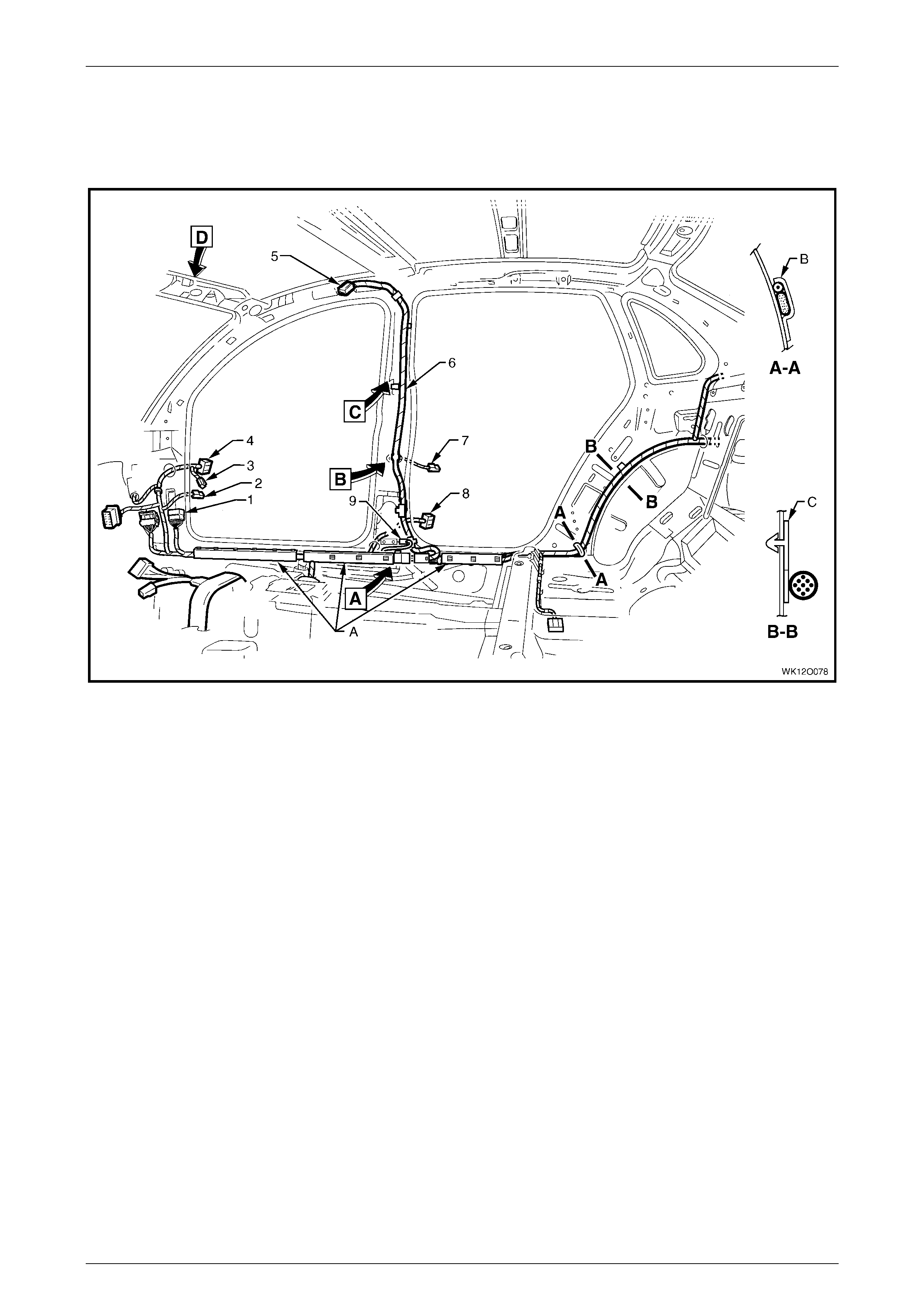
Fuses, Relays and Wi ring Harnesse s Page 12O–93
Page 12O–93
3.59 Body and Roof Wiring Harnesses – 1
Interior – RHD
Figure 12O – 77
Legend
1 Body Wiring Harness to Main Wi ring Harness Connector
(X201)
2 Door Ajar Indicator Switch Connector (S2)
3 Body Wiring Harness to Right-hand Front Door Wi ri ng
Harness Connect or (X601)
4 Body Wiring Harness to Right-hand Front Door Wi ri ng
Harness Connect or (X600)
5 Roof Lamp Harness to Visor Lamp Harness
Connector (X310)
6 Roof Lamp Harness
7 Door Ajar Indicator Switch Connector (S2)
8 Body Wiring Harness to Right-hand Rear Door Wiring
Harness Connect or (X800)
9 Inflation Restraint Side Impact Sensor Connector (A66)
A Harness clipped to underbody, refer to
3.61 Body and Roof Wiring Harnesses – 3.
B Clip bent to ret ain fuel filter door cable & body harness.
C Clip bent to retain f uel filter door cable & body harness
(2 places).
For views A through D, refer to
3.62 Body and Roof Wiring Harnesses – 4.
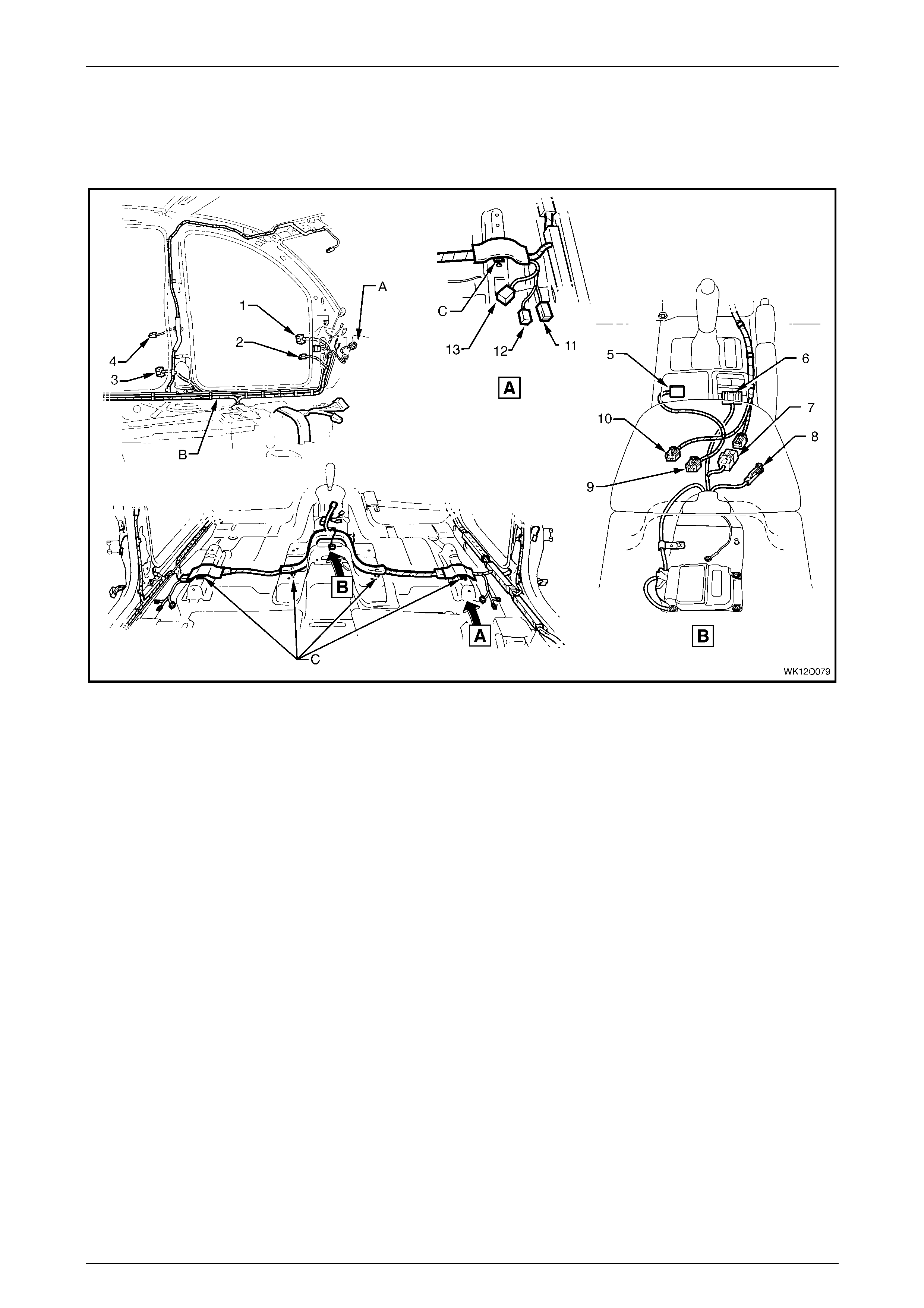
Fuses, Relays and Wi ring Harnesse s Page 12O–94
Page 12O–94
3.60 Body and Roof Wiring Harnesses – 2
Inte rior – RHD
Figure 12O – 78
Legend
1 Body Wiring Harness to Left-hand Front Door Wiri ng
Harness Connect or (X500).
2 Door Ajar Indicator Switch Connector (S2).
3 Body Wiring Harness to Left-hand Front Door Wiri ng
Harness Connect or (X700)
4 Door Ajar Indicator Switch Connector (S2).
5 Main Wiring Harness to Transmission Select or Harness
Connector (X301)
6 Side Window (Master) Switch Connector (S222)
7 Body Wiring Harness to Main Wi ring Harness Connector
(X303)
8 Park Brake Switc h Connect or (S181)
9 Hazard Warning S witch Connector (S120)
10 Main Wiring Harness t o Consol e Wiring Harness Connector
(X309).
11 Seat Belt Connector (Y 128 - D)(Y129 – P)
12 Body Wiring harness to Side Airbag Harness Connector
(X306 – L) (X307 – R)
13 Body Wiring Harness to Power Seat Harness Connector
(X302 – D) (X308 – P) – (X315– D Level 5 Only)
A For continuation, refer to
3.61 Body and Roof Wiring Harnesses – 3.
B Harness cli pped to under body, refer to
3.61 Body and Roof Wiring Harnesses – 3.
C Harness clipped to under body as shown (4 places).
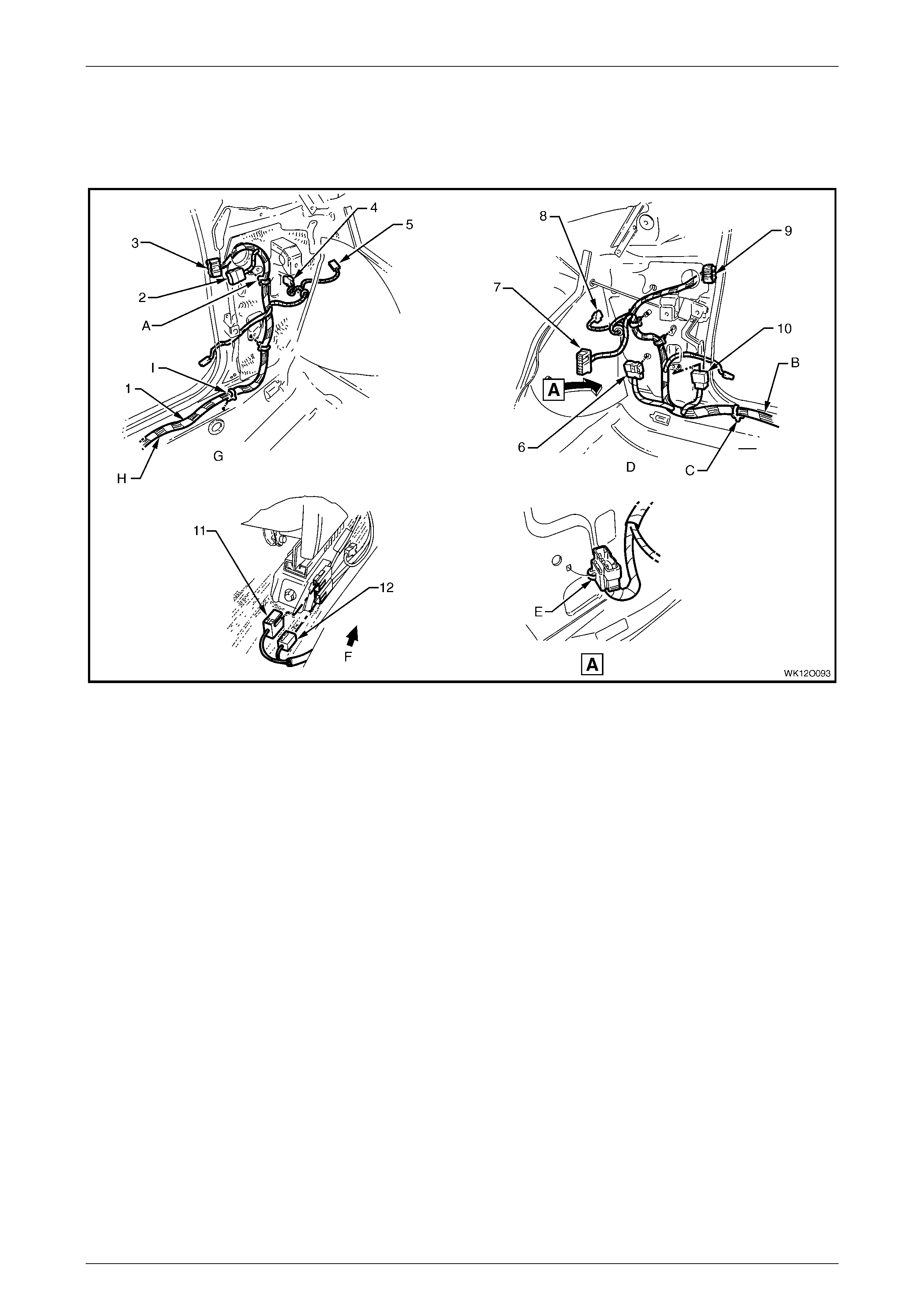
Fuses, Relays and Wi ring Harnesse s Page 12O–95
Page 12O–95
3.61 Body and Roof Wiring Harnesses – 3
Inte rior – RHD
Figure 12O – 79
Legend
1 Body Wiring Harness
2 Body Wiring Harness to Main Wi ring Harness Connector
(X202)
3 Body Wiring Harness to Left-hand Front Door Wiri ng
Harness Connect or (X500)
4 Front Side Turn Signal Lamp Connector (E75)
5 Radio Power Antenna Connector (W6 – X1)
6 Body Wiring Harness to Main Wi ring Harness Connector
(X200)
7 Body Control Module Connect or (A15 – X4)
8 Front Side Turn Signal Lamp Connector (E75)
9 Body Wiring Harness to Right-hand Front Door Wi ri ng
Harness Connect or (X600)
10 Body Wiring Harness to Main Wi ring Harness Connector
(X201)
11 Body Wiring Harness to Side Airbag Harness Connector
(X306 – L, X307 – R)
12 Seat Belt Connector (Y 128 – D), (Y129 – P)
A Attach body wiring harness to shroud side panel (2 places).
B For continuation, refer to 3.59 Body and Roof Wiring
Harnesses – 1.
C Body wiring harness att ached t o under body as shown
(9 places).
D Right-hand side shown.
E Main wiring harness connect or cl i pped to shroud side panel
as shown.
F Front of vehicle.
G Left-hand side shown.
H For continuation, ref er to 3.60 Body and Roof Wiring
Harnesses – 2.
I Body wiring harness att ached t o under body as shown
(6 places).
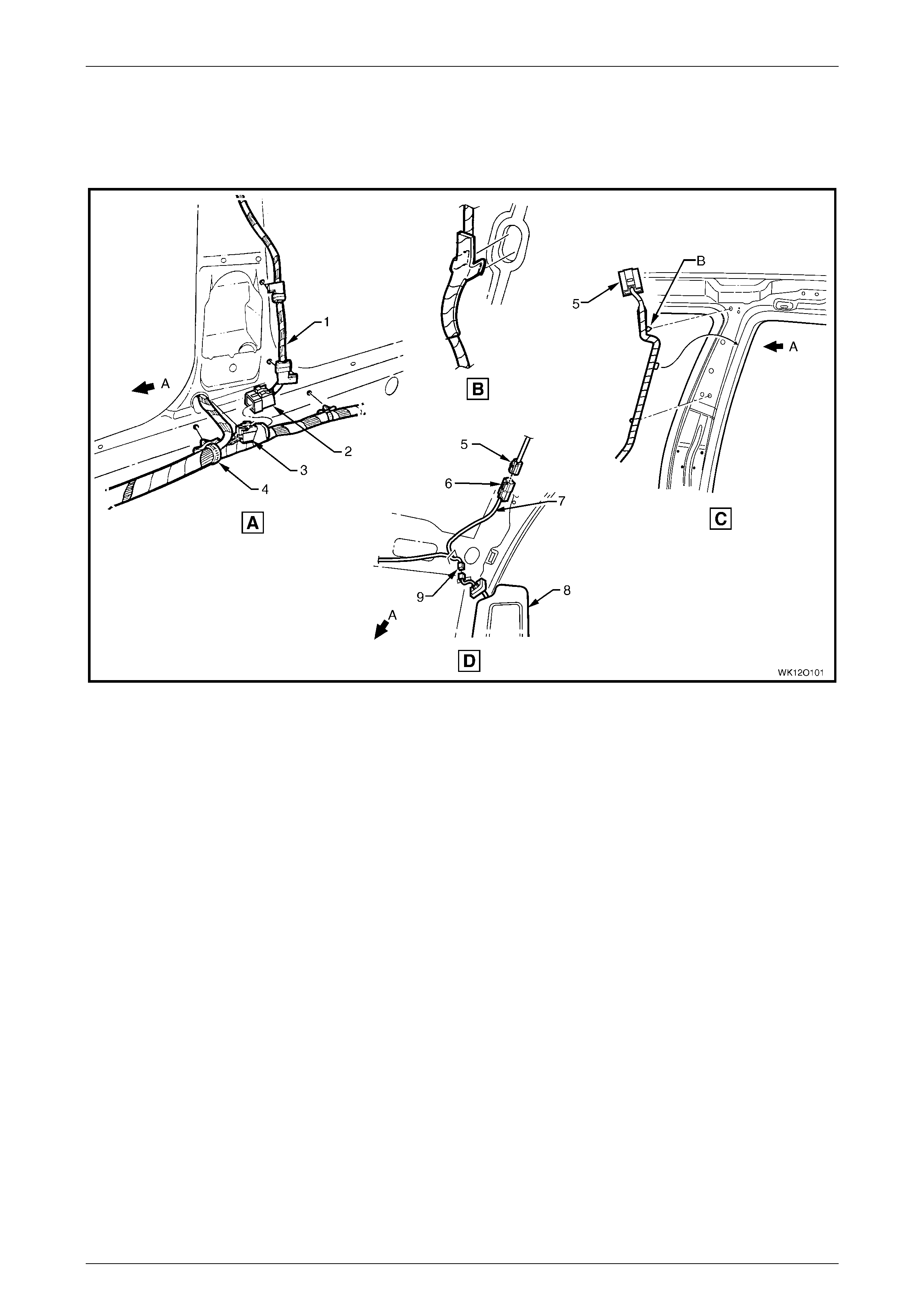
Fuses, Relays and Wi ring Harnesse s Page 12O–96
Page 12O–96
3.62 Body and Roof Wiring Harnesses – 4
Interior
Figure 12O – 80
Legend
1 Roof Lamp Harness
2 Roof Lamp Harness to Body Wiri ng Harness Connector
(X300)
3 Body Wiring Harness to Roof Lamp Harness Connector
(X300)
4 Body Wiring Harness
5 Roof Lamp Harness to Visor Lamp Harness Connector
(X310)
6 Visor Lamp Harness to Roof Lamp Harness Connector
(X310)
7 Visor Lamp Harness
8 Sun Visor
9 Sun Shade Lamp Connector (E120)
A Front of vehicle.
B For clipping, refer to
3.60 Body and Roof Wiring Harnesses – 2 and
3.61 Body and Roof Wiring Harnesses – 3.
For location of views A through D, refer to 3.59 Body and Roof
Wiring Harnesses – 1.
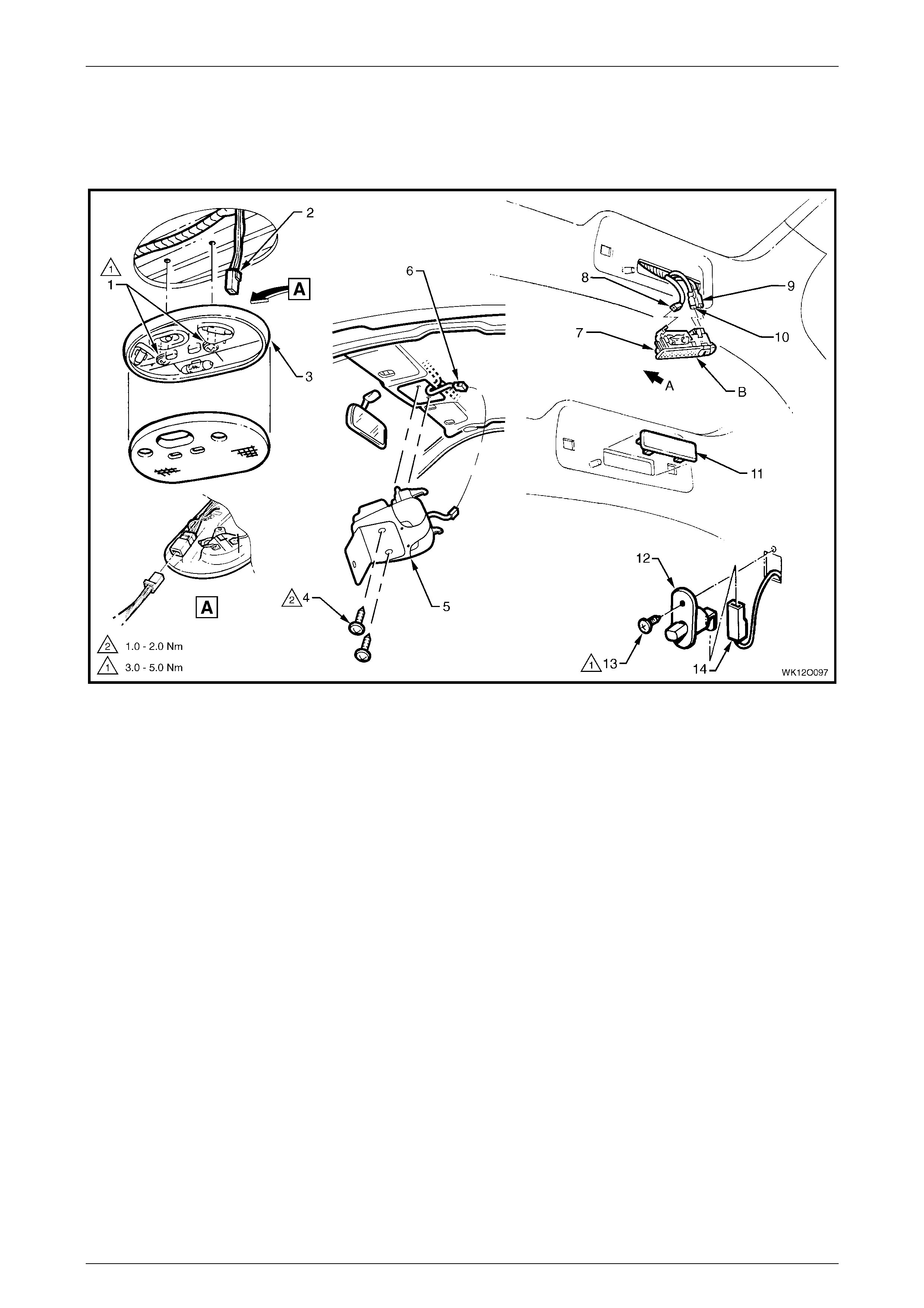
Fuses, Relays and Wi ring Harnesse s Page 12O–97
Page 12O–97
3.63 Body and Roof Wiring Harnesses – 5
Dome and Rear Passenger Compartment Lamps
Figure 12O – 81
Legend
1 Attachi ng Screws Dome Lamp
2 Dome Lamp Connector (E67)
3 Dome Lamp Assembly (Level 1)
4 Attaching Screws
5 Roof Console (Level 2 to 5)
6 Dome Lamp Connector (E67)
7 Reading Lamp Assembly
8 Reading Lamp Connect or (E94 – X1)
9 Reading Lamp Connect or (E94 – X2)
10 Reading Lamp Connect or (E94 – X3)
11 Reading Lamp Blanking Blank (Level 1)
12 Door Ajar Warning Switch
13 Attachi ng Screw Door Ajar Warning Switch
14 Door Ajar Warning Switch Connector (S2)
A. Front of vehicle.
B. Install l amp with switc h facing rear on ri ght-side, forward on
left-side.
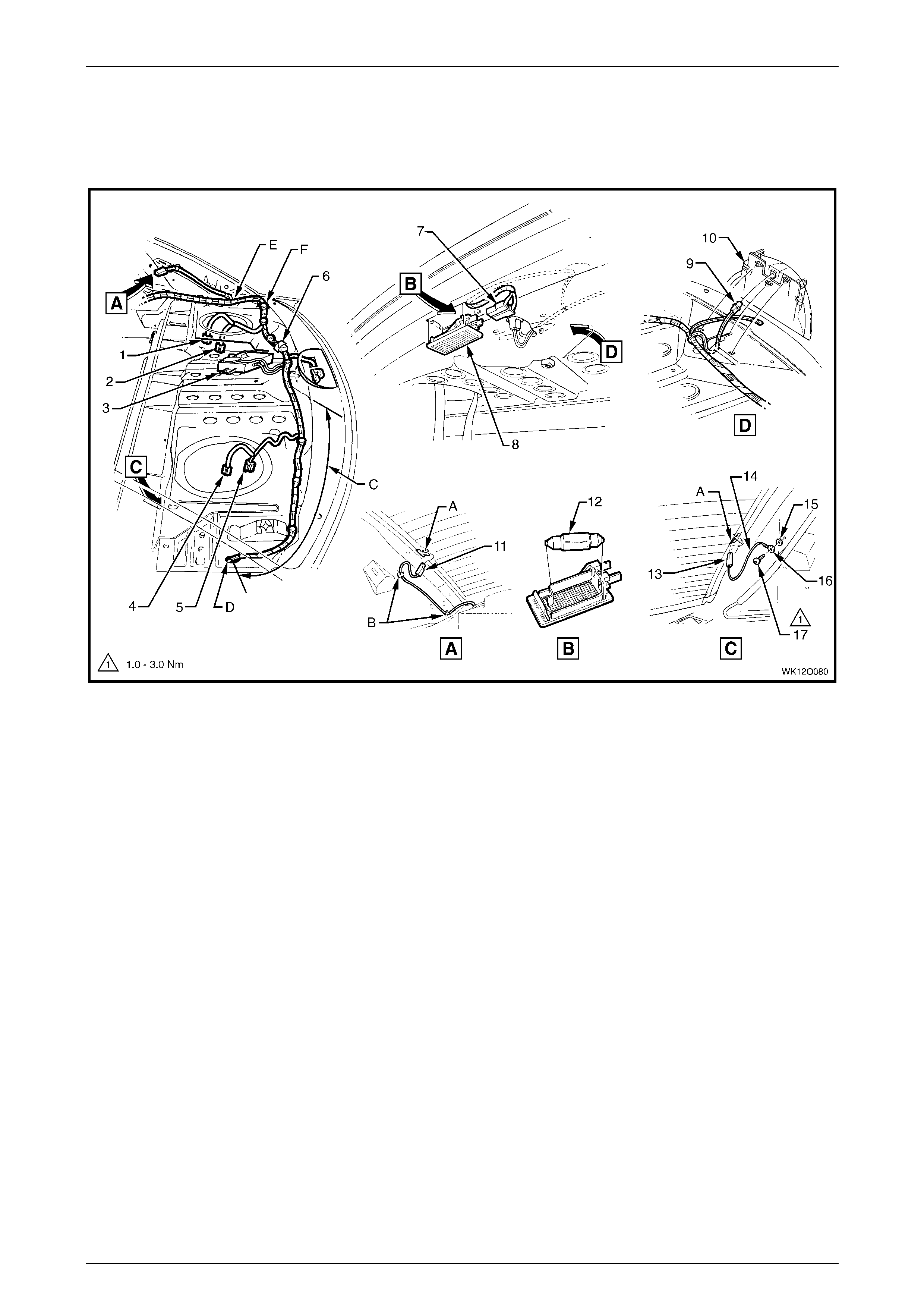
Fuses, Relays and Wi ring Harnesse s Page 12O–98
Page 12O–98
3.64 Body and Roof Wiring Harnesses – 6
Parcel Shelf and Rear Compartment Lamp
Figure 12O – 82
Legend
1 Right-hand Rear Radio Speaker Connect or (B 131 – X2)
2 Right-hand Rear Radio Speaker Connect or (B 131 – X1)
3 Reverse Park i ng Aid Module and Speaker Assembl y
4 Left-hand Rear Radio Speaker Connector (B131 – X2)
5 Left-hand Rear Radio Speaker Connector (B131 – X1)
6 Body Wiring Harness to Headphone Harness Connec tor
(X404)
7 Rear Compartment Courtesy Lamp Connectors (E36)
8 Rear Compartment Courtesy Lamp
9 High Mounted Stop Lamp Connector (E79)
10 High Mounted Stop Lamp
11 Rear Window Defog Grid Connector (R22 – X1)
12 Rear Compartment Courtesy Lamp Bulb
13 Rear Window Defog Grid Connector (R22 – X2)
14 Rear Window Defog Grid Earth Lead
15 Earth Lead Terminal Attaching Washer
16 Earth Lead Terminal (X118 – GP7)
17 Earth Lead Terminal Attaching Screw
A Tab bent once lead connector is installed.
B Rear window defog grid lead cli p to side inner panel
(2 places).
C Rear speaker wiring where fitted.
D For continuation, ref er to
3.52 Radio Amplifier and Antenna Wiring – 2 and
3.53 Radio Amplifier and Antenna Wiring – 3.
E For continuation, refer to
3.65 Body and Roof Wiring Harnesses – 7.
F Body wiring harness cli pped to rear seat upper panel
(7 places).
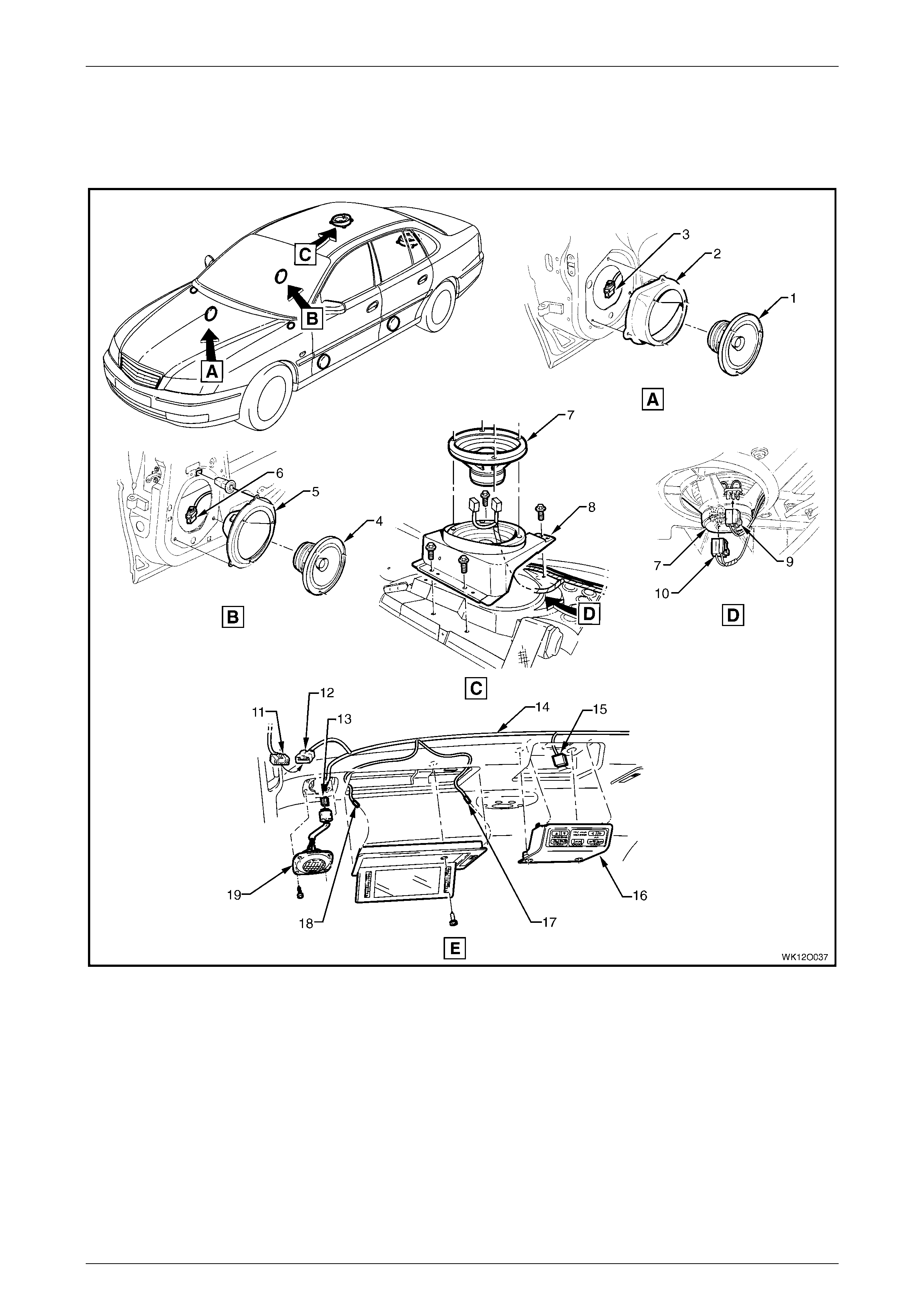
Fuses, Relays and Wi ring Harnesse s Page 12O–99
Page 12O–99
3.65 Body and Roof Wiring Harnesses – 7
Speakers and Rear Roof Control Units
Figure 12O – 83

Fuses, Relays and Wi ring Harnesse s Page 12O–100
Page 12O–100
Legend
1 Front Door Radio Speaker Assembly
2 Front Door Radio Speaker Mounting Box Assembl y
3 Front Right-hand Door Radi o Speaker Connector (B108)
4 Rear Door Radio Speaker Assembly
5 Rear Door Radio Speaker Mounti ng Box Assembl y
6 Rear Right-hand Door Radio S peaker Connect or (B117)
7 Rear Shelf Radio Speaker
8 Rear Shelf Radio Speaker B rack et
9 Rear Left-hand Door Radio S peaker Connect o r (B 131 – X1)
10 Rear Left-hand Door Radio S peaker Connect or (B131 – X2)
11 Body Wiring Harness to Audio Remote Harness Connector
(X316)
12 Audio Remote Harness to Body Wiring Harness Connector
(X316)
13 Radio Roof Speaker Connect or (B116)
14 Audio Remote Harness
15 Radio and Climate Control Module Connector (A94)
16 Radio and Climate Control Module
17 Vanity Lamp Connector (E 90 – X1)
18 Vanity Lamp Connector (E 90 – X2)
19 Radio Roof Speaker
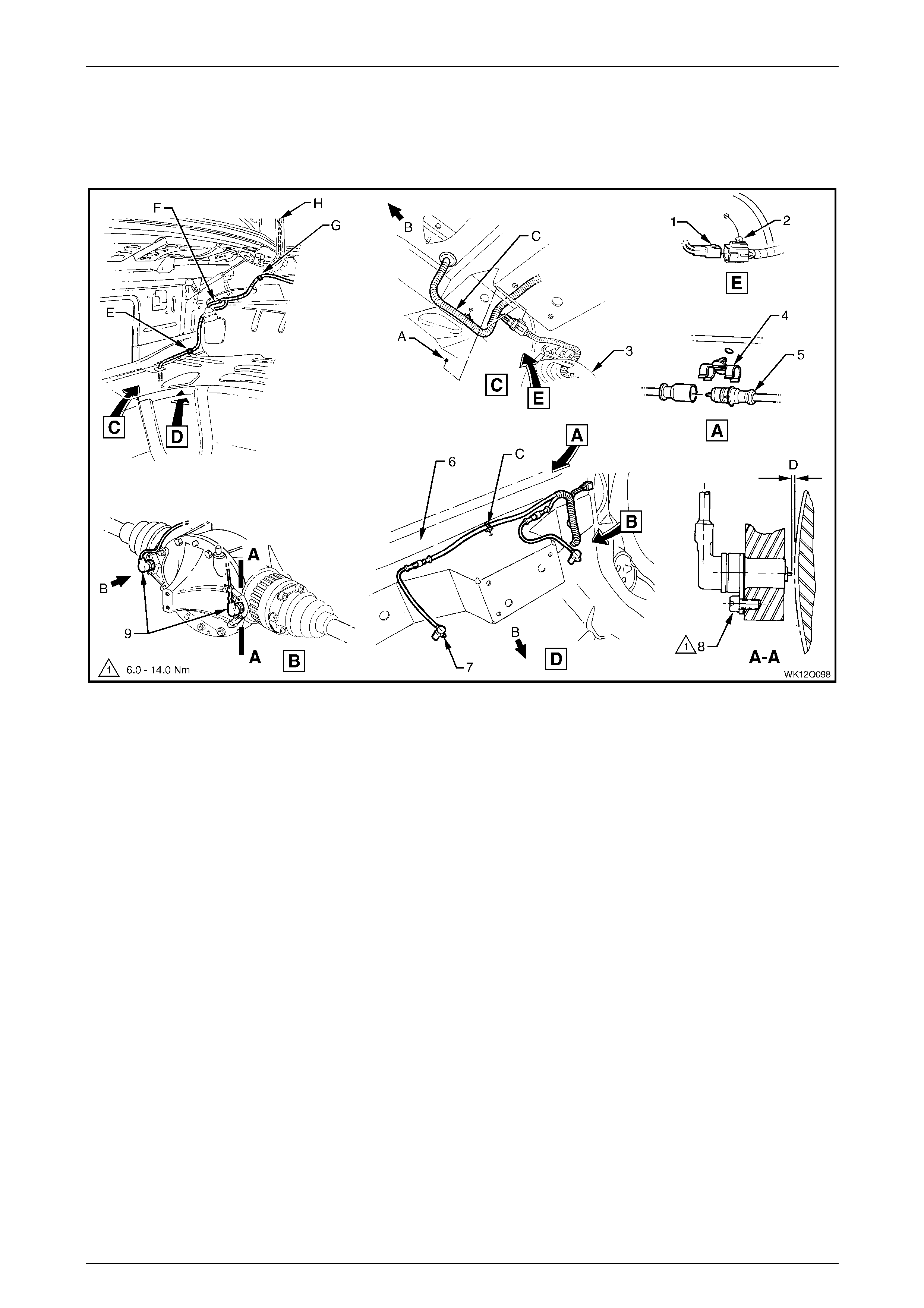
Fuses, Relays and Wi ring Harnesse s Page 12O–101
Page 12O–101
3.66 Body and Roof Wiring Harnesses – 8
Rear Compartment, Fuel Tank and ABS
Figure 12O – 84
Legend
1 Body Wiring Harness to Fuel Tank Harness Connector
(X402)
2 Fuel Tank Harness to Body Wiring Harness Connect or
(X402)
3 Fuel Tank Assembly
4 Rear Wheel Speed Sensor Connector Retainer
5 Rear Wheel Speed Sensor Connector (B76)
6 Rear Axle Cross Member
7 Sensor Assembly Rear Wheel Speed
8 Attachi ng Screw Sensor Assembl y Rear Wheel Speed
9 Differential Assembly with Rear Speed Sensors Install ed
A Harness connector clip to rear longitudinal extension panel.
B Front of vehicle.
C Body wiring harness cl i pped to rear axle cross member
(2 places).
D Shims used to achieve required clearanc e between tip of
wheel speed sensor and pulse ring of 0.3 to 1.1 mm.
E Body wiring harness cli pped to lo wer wheelhouse brace –
right-hand si de.
F For continuation, refer to
3.59 Body and Roof Wiring Harnesses – 1.
G Body wiring harness clipped to side inner panel.
H For continuation, ref er to
3.70 Body and Roof Wiring Harnesses – 12.
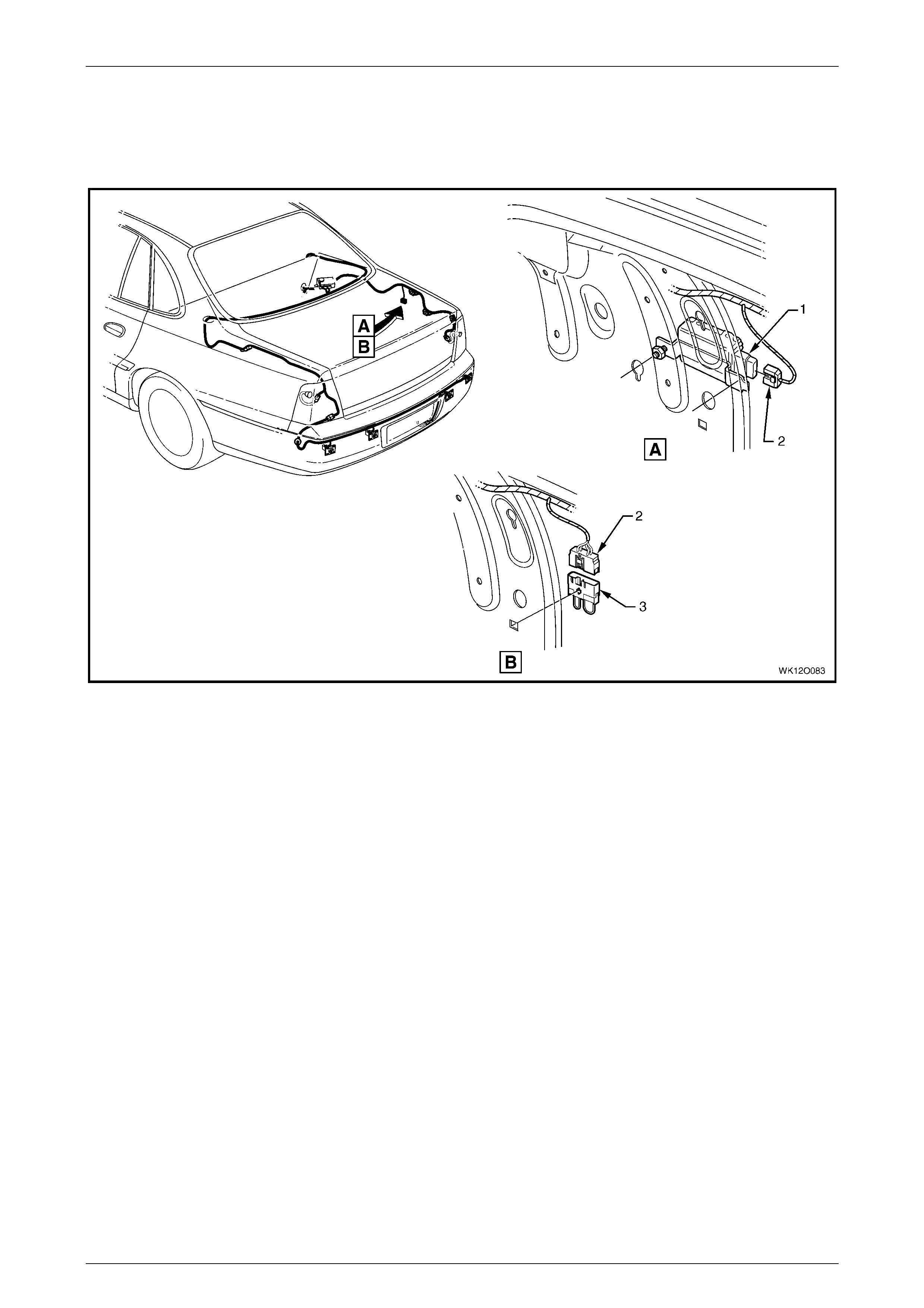
Fuses, Relays and Wi ring Harnesse s Page 12O–102
Page 12O–102
3.67 Body and Roof Wiring Harnesses – 9
Fuel Pump Module – V6 Supercharged Engine
Figure 12O – 85
Legend
1 Fuel Pump Module Assembly
2 Fuel Pump Module Connector (A47) 3 Fuel Pump Module Shorting Plug (A47)
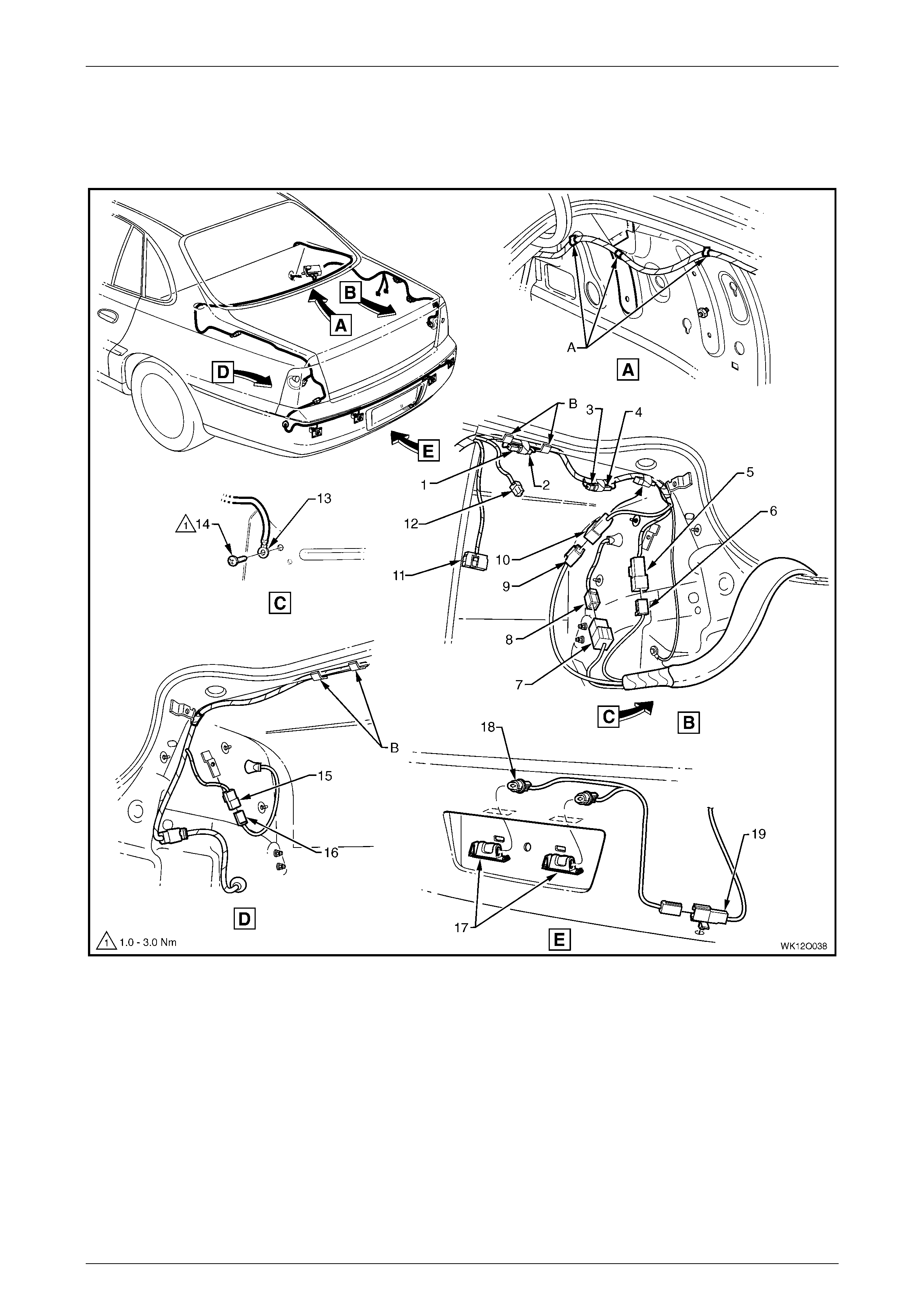
Fuses, Relays and Wi ring Harnesse s Page 12O–103
Page 12O–103
3.68 Body and Roof Wiring Harnesses – 10
Rear Compartment – Level 4
Figure 12O – 86

Fuses, Relays and Wi ring Harnesse s Page 12O–104
Page 12O–104
Legend
1 Body Wiring Harness to Tow Hook A Connector (X906)
2 Body Wiring Harness to Tow Hook B Connector (X906)
3 Body Wiring Harness to Trailer B Connector (X907)
4 Body Wiring Harness to Trailer A Connector (X907)
5 Body Wiring Harness to Right-hand Tai l Lamp Harness
Connector (X903)
6 Trailer Harness t o Body Wiri ng Harness Connector
(X38 – B)
7 Trailer Harness t o Body Wiri ng Harness Connector
(X38 – A)
8 Right-hand Tail Lamp Harness to Body Wiring Harness
Connector (X903)
9 Trailer Harness t o Body Wiri ng Harness Connector (X908)
10 Body Wiring Harness to Trailer Harnes s Connector (X908)
11 Fuel Pump Module Connector (A47)
12 Access ory P ower Connector (X112 – AUX)
13 Body Wiring Harness Tail Lamp Ground Terminal
(X118 – GP13)
14 Screw, Body Earth
15 Body Wiring Harness to Left-hand Tail Lam p Harness
Connector (X904)
16 Left-hand Tail Lamp Harness t o Body Wiri ng Harness
Connector (X904)
17 Rear Licence Plate Lam p Assembly
18 Rear Licence Plate Lam p Bulb
19 Rear Licence Plate Lam p Connector (E44)
A Body wiring harness clipped to side inner panel.
B Clip bent to retain body wiring harnes s.
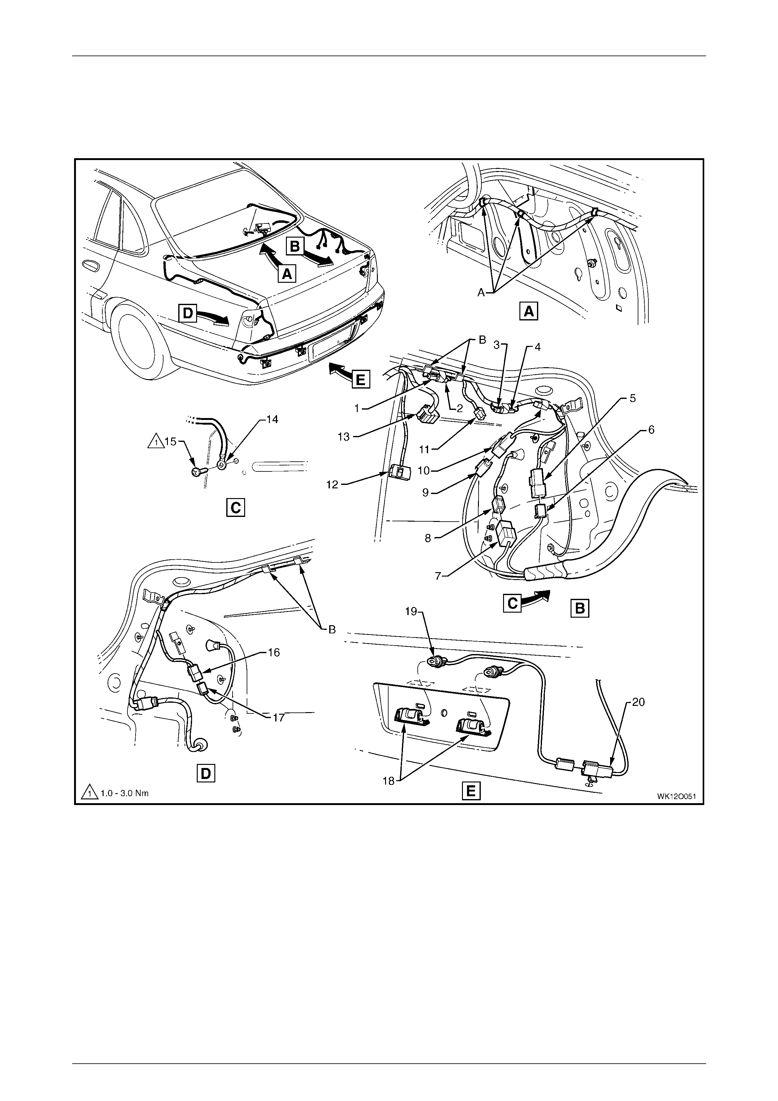
Fuses, Relays and Wi ring Harnesse s Page 12O–105
Page 12O–105
3.69 Body and Roof Wiring Harnesses – 11
Rear Compartment – Level 5
Figure 12O – 87

Fuses, Relays and Wi ring Harnesse s Page 12O–106
Page 12O–106
Legend
1 Body Wiring Harness to Tow Hook A Connector (X906)
2 Body Wiring Harness to Tow Hook B Connector (X906)
3 Body Wiring Harness to Trailer B Connector (X907)
4 Body Wiring Harness to Trailer A Connector (X907)
5 Body Wiring Harness to Right-hand Tai l Lamp Harness
Connector (X903)
6 Trailer Harness t o Body Wiri ng Harness Connector
(X38 – B)
7 Trailer Harness t o Body Wiri ng Harness Connector
(X38 – A)
8 Right-hand Tail Lamp Harness to Body Wiring Harness
Connector (X903)
9 Trailer Harness t o Body Wiring Harness Connector (X908)
10 Body Wiring Harness to Trailer Harnes s Connector (X908)
11 Access ory P ower Connector (X112 – AUX)
12 Fuel Pump Module Connector (A47)
13 Body Wiring Harness to Audio Patch Harness
Connector (X403)
14 Body Wiring Harness Tail Lamp Ground Terminal
(X118 – GP13)
15 Screw, Body Earth
16 Body Wiring Harness to Left-hand Tail Lam p Harness
Connector (X904)
17 Left-hand Tail Lamp Harness t o Body Wiri ng Harness
Connector (X904)
18 Rear Licence Plate Lam p Assembly
19 Rear Licence Plate Lam p Bulb
20 Rear Licence Plate Lam p Connector (E44)
A Body wiring harness clipped to side inner panel.
B Clip bent to retain body wiring harnes s.
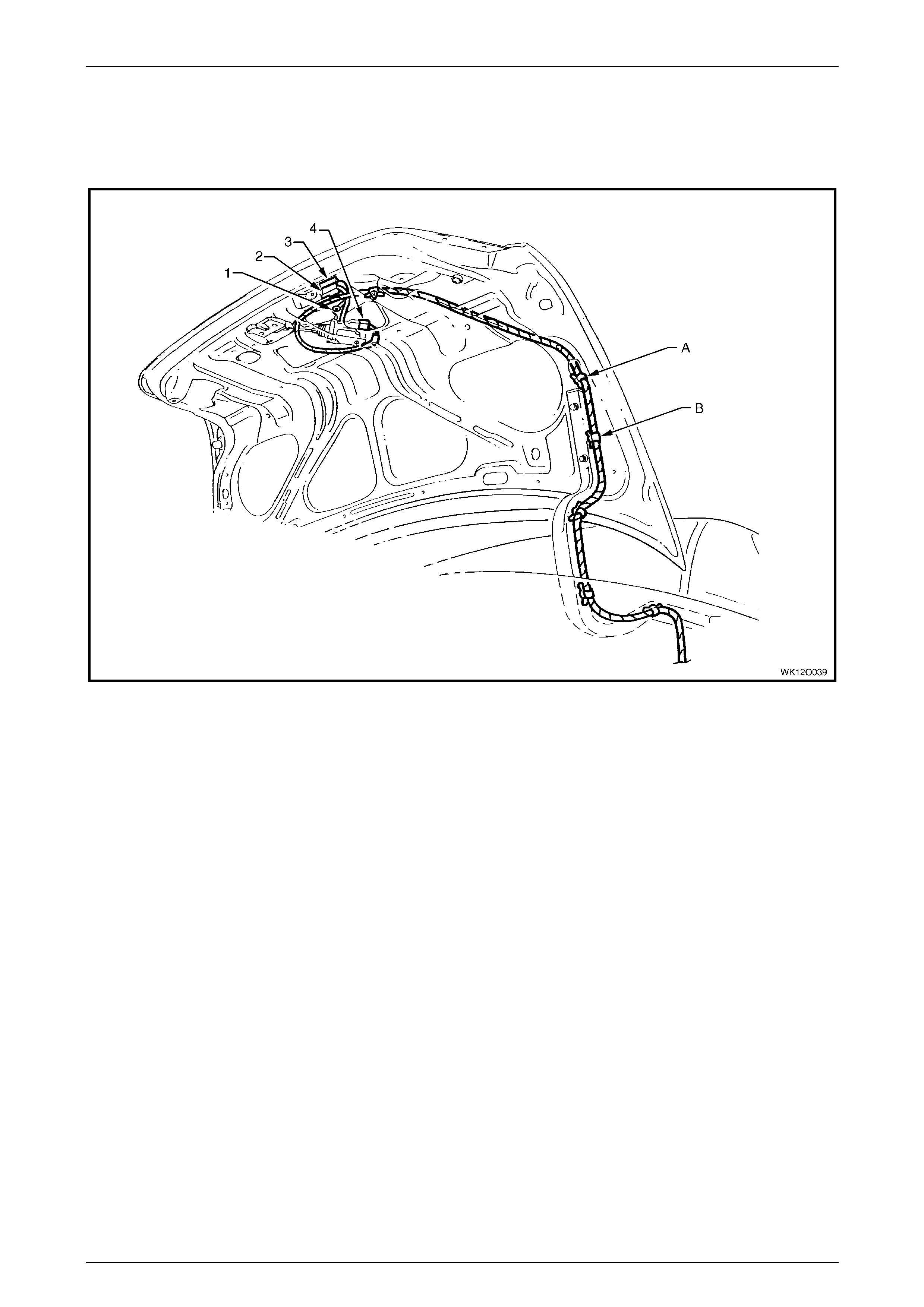
Fuses, Relays and Wi ring Harnesse s Page 12O–107
Page 12O–107
3.70 Body and Roof Wiring Harnesses – 12
Rear Compartment Lid
Figure 12O – 88
Legend
1 Body Wiring Harness Ground Deck Li d Terminal
(X118 – GP14)
2 Rear Compartment Theft Det errent S witch Connect or
(S189 – X2)
3 Rear Compartment Courtesy Lamp Switch Connector
(S189 – X1)
4 Rear Compartment Lid Latc h Actuator Connec tor (Y29)
A Body wiring harness cli pped to rear compartm ent li d inner
(4 places).
B Body wiring harness cli pped to rear compartment l i d hinge
(4 places).
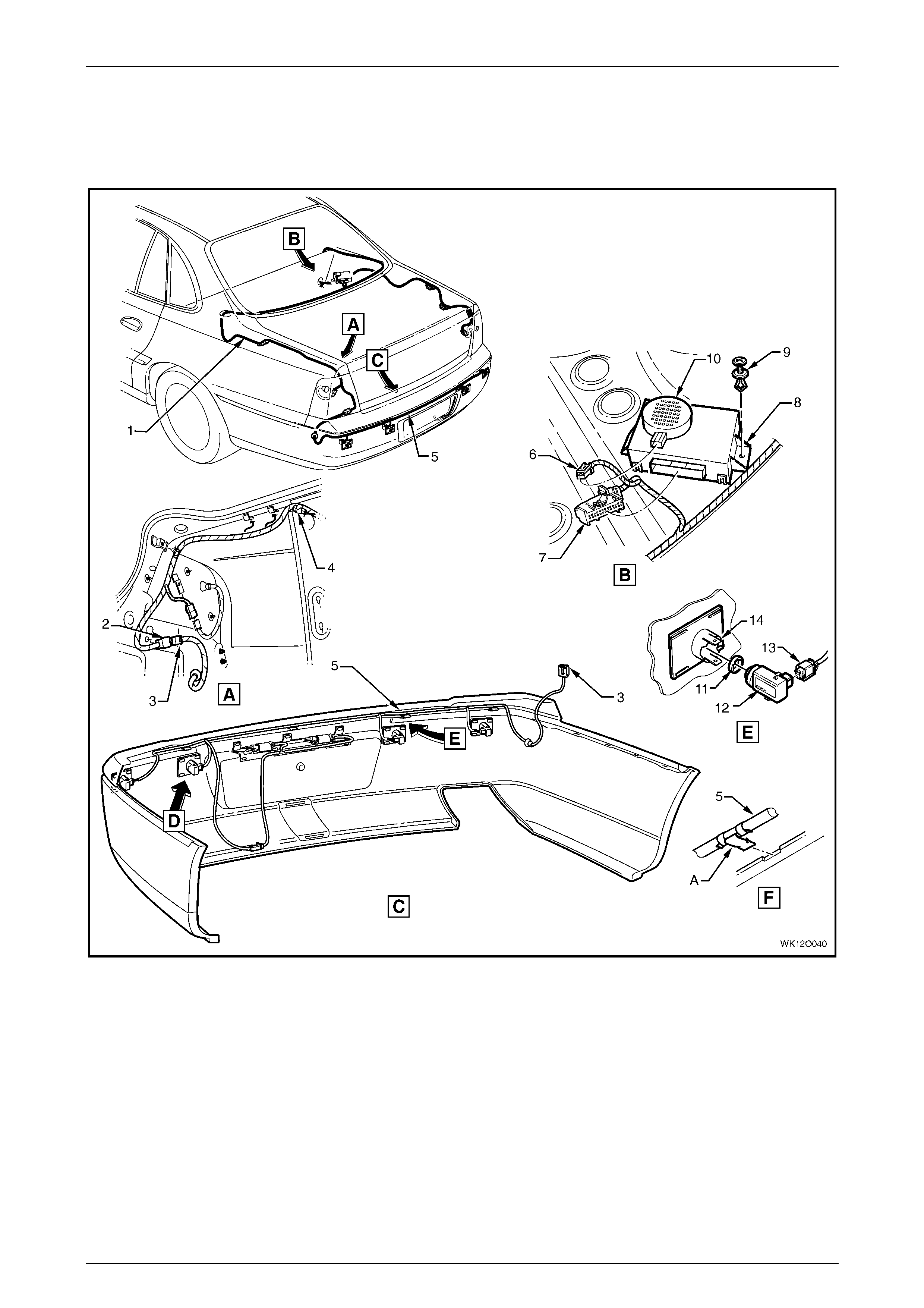
Fuses, Relays and Wi ring Harnesse s Page 12O–108
Page 12O–108
3.71 Body and Roof Wiring Harnesses – 13
Reverse Parking Aid
Figure 12O – 89
Legend
1 Body Wiring Harness
2 Body Wiring Harness to Reverse Parking Aid Harness
Connector (X905)
3 Reverse Park i ng Ai d Harness t o Body Wi ri ng Harness
Connector (X905)
4 Inline to Rear Object Sensor Harnes s Connector (X156)
5 Reverse Park i ng Aid Harness
6 Rear Object Sensor Alarm Connect or (H31)
7 Rear Object Sensor Control Connec t or (A98)
8 Rear Object Sensor Control Module
9 Retaining Screw (2 Places )
10 Rear Object Sensor Alarm
11 Rear Object Sensor Ring
12 Rear Object Sensor Assembl y
13 Rear Object Sensor Connector (B133)
14 Rear Object Sensor Housing
A Reverse parking ai d harness cl i pped as shown (4 places).
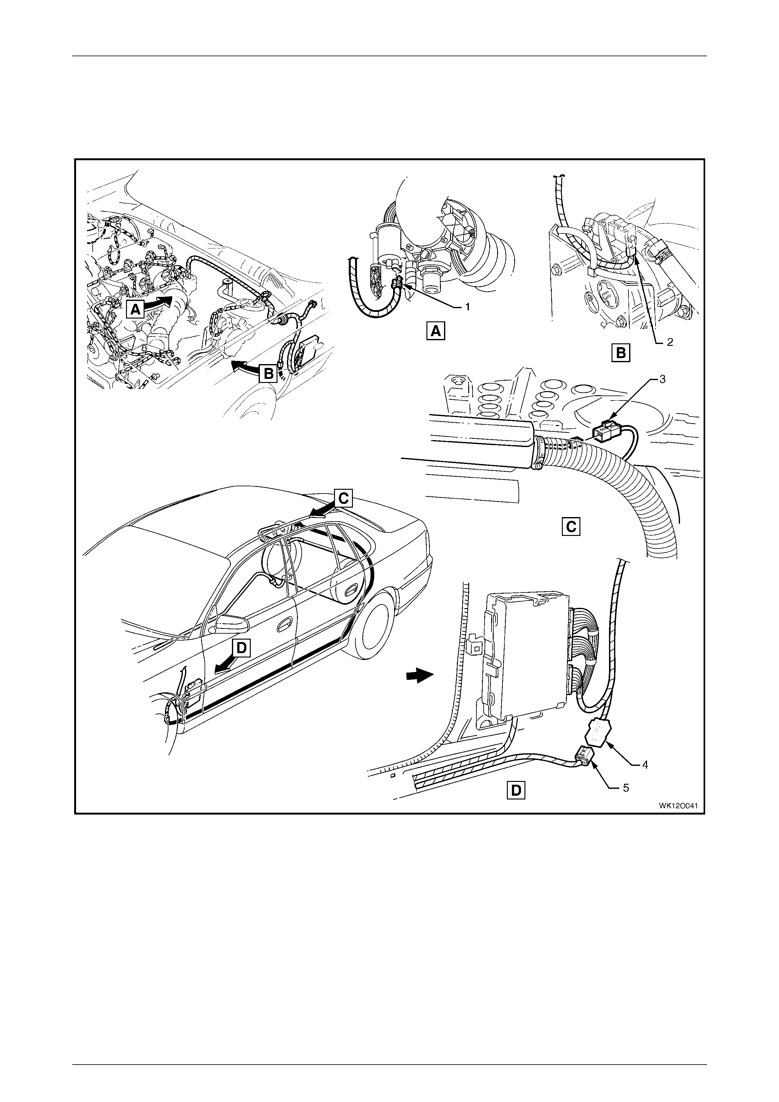
Fuses, Relays and Wi ring Harnesse s Page 12O–109
Page 12O–109
3.72 Body Wiring Harness – 1
LPG – RHD
Figure 12O – 90
Legend
1 Fuel Control Solenoid Valve Connector (Y143 – FCSV)
2 Lock-Off Solenoi d Val ve Connect or (Y143 – LOSV)
3 Fuel Sender and Pump Control Module Connector (A55)
4 Powertrain Harness to LPG Harness Connector (X203)
5 LPG Harness to Powertrain Harness Connector (X203)
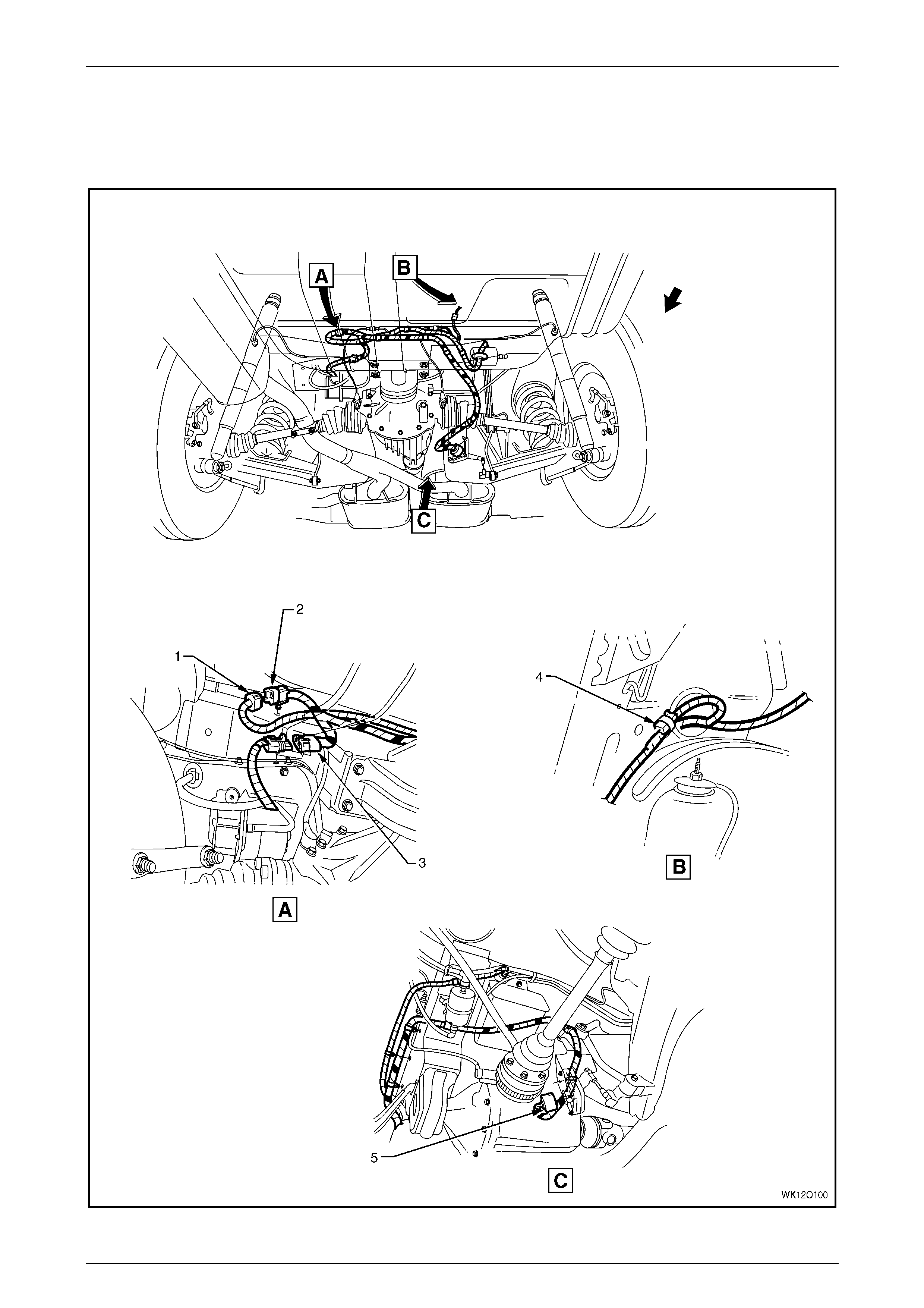
Fuses, Relays and Wi ring Harnesse s Page 12O–110
Page 12O–110
3.73 Body Wiring Harness – 2
Level Ride System
Figure 12O – 91

Fuses, Relays and Wi ring Harnesse s Page 12O–111
Page 12O–111
Legend
1 Body Wiring Harness to Level Ri de Harness Connector
(X401)
2 Level Ride Harness t o Body Wi ri ng Harness Connector
(X401)
3 Auto Level Control Module Connec tor (A8 – COMP)
4 Level Ride Suppress i on Di ode (V8)
5 Auto Level Control Module Connector (A8 – SNSR)
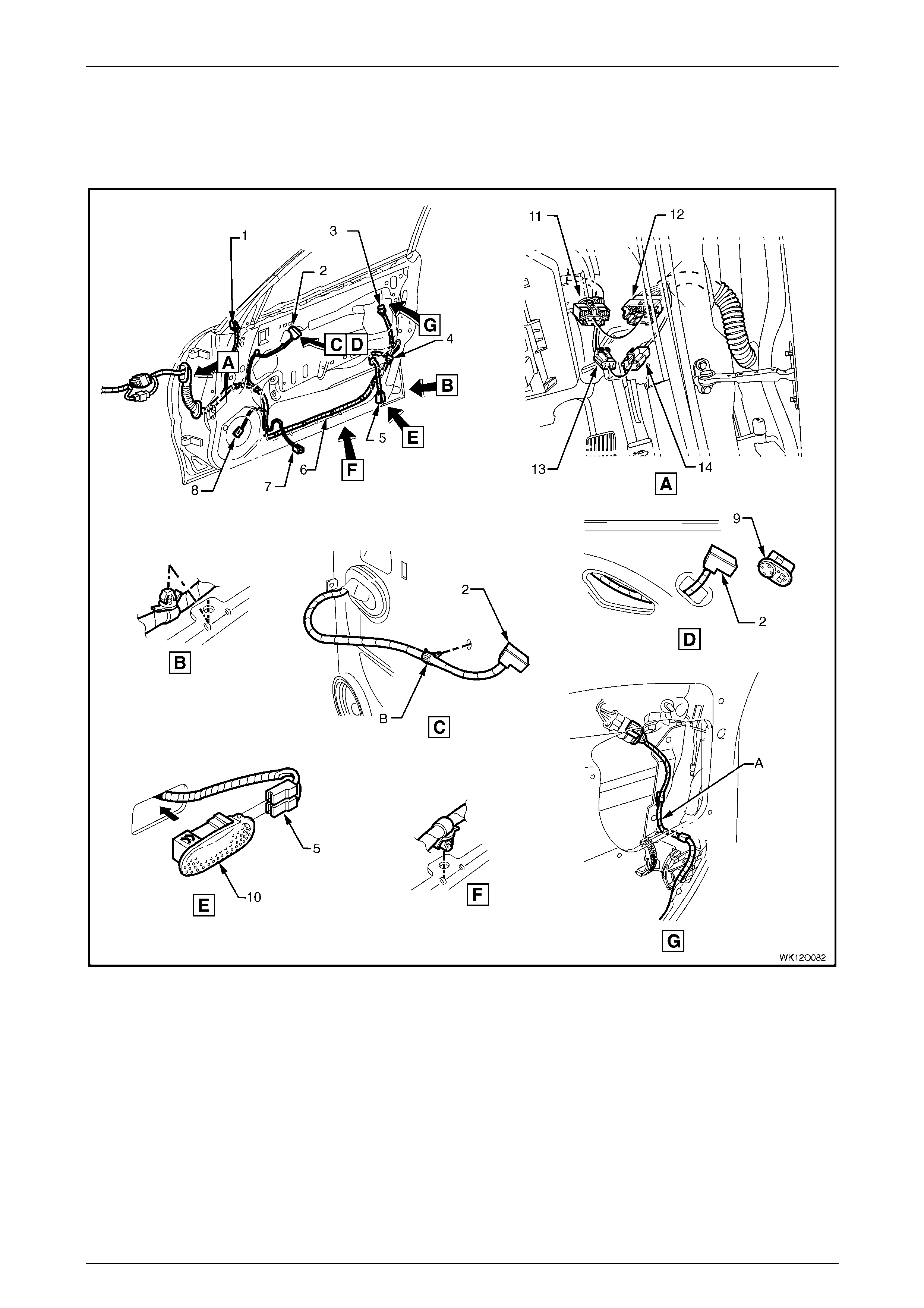
Fuses, Relays and Wi ring Harnesse s Page 12O–112
Page 12O–112
3.74 Door Wiring Harness – 1
Front Door – RHD – Level 4
Figure 12O – 92

Fuses, Relays and Wi ring Harnesse s Page 12O–113
Page 12O–113
Legend
1 Outside Rear View Mirror Motor Connect or (M11)
2 Outside Rear View Mirror Rem ote Control S witc h Connector
(S169)
3 Door Lock Switc h Connect or (S63)
4 Front Side Door Lock Actuat or Connect o r (Y 13)
5 Front Side Door Courtes y Lamp Connectors (E72)
6 Door Wiring Harness
7 Front Side Door Window Regulator Connect or (M10)
8 Radio Door Speaker Connect or (B108)
9 Outside Rear View Mirror Rem ote Control S witc h
10 Front Side Door Courtesy Lamp
11 Body Wiring Harness to Right-hand Front Door Wi ri ng
Harness Connect or (X600)
12 Right-hand Front Door Wi ri ng Harness t o Body Wi ri ng
Harness Connect or (X600)
13 Body Wiring Harness to Right-hand Front Door Wi ri ng
Harness Connect or (X601)
14 Right-hand Front Door Wi ri ng Harness t o Body Wi ri ng
Harness Connect or (X601)
A Harness rout ed as shown.
B Harness cli pped to door inner panel as shown.
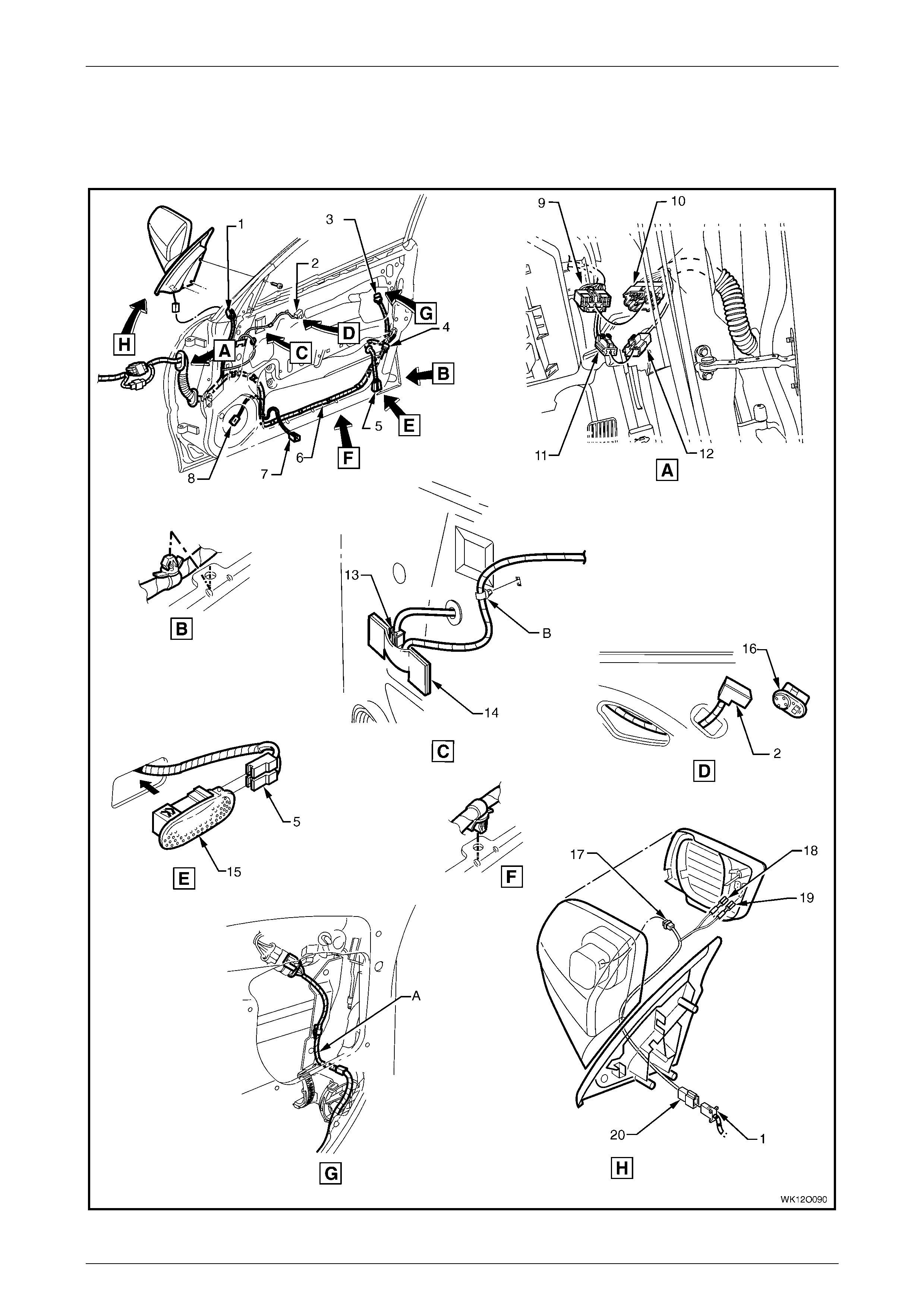
Fuses, Relays and Wi ring Harnesse s Page 12O–114
Page 12O–114
3.75 Door Wiring Harness – 2
Front Door – RHD – Level 5
Figure 12O – 93

Fuses, Relays and Wi ring Harnesse s Page 12O–115
Page 12O–115
Legend
1 Right-hand Front Door Wi ri ng Harness t o Power Mirror
Harness Connect or (X602)
2 Outside Rear View Mirror Rem ote Control S witc h Connector
(S169)
3 Door Lock Switc h Connect or (S63)
4 Front Side Door Lock Actuat or Connect o r (Y 13)
5 Front Side Door Courtes y Lamp Connectors (E72)
6 Door Wiring Harness
7 Front Side Door Window Regulator Connect or (M10)
8 Radio Door Speaker Connect or (B108)
9 Body Wiring Harness to Right-hand Front Door Wi ri ng
Harness Connect or (X600)
10 Right-hand Front Door Wi ri ng Harness t o Body Wiri ng
Harness Connect or (X600)
11 Body Wiring Harness to Right-hand Front Door Wi ri ng
Harness Connect or (X601)
12 Right-hand Front Door Wi ri ng Harness t o Body Wi ri ng
Harness Connect or (X601)
13 Rear View Mirror Memory Module Connect or (A 73 – X2)
14 Rear View Mirror Memory Module
15 Front Side Door Courtesy Lamp
16 Outside Rear View Mirror Rem ote Control S witc h
17 Outside Rear View Mirror Connector (M11 – X1)
18 Outside Rear View Mirror Connector (M11 – X2)
19 Outside Rear View Mirror Connector (M11 – X3)
20 Power Mirror Harness to Right-hand Front Door Wiring
Harness Connect or (X602)
A Harness rout ed as shown.
B Harness cli pped to door inner panel as shown.
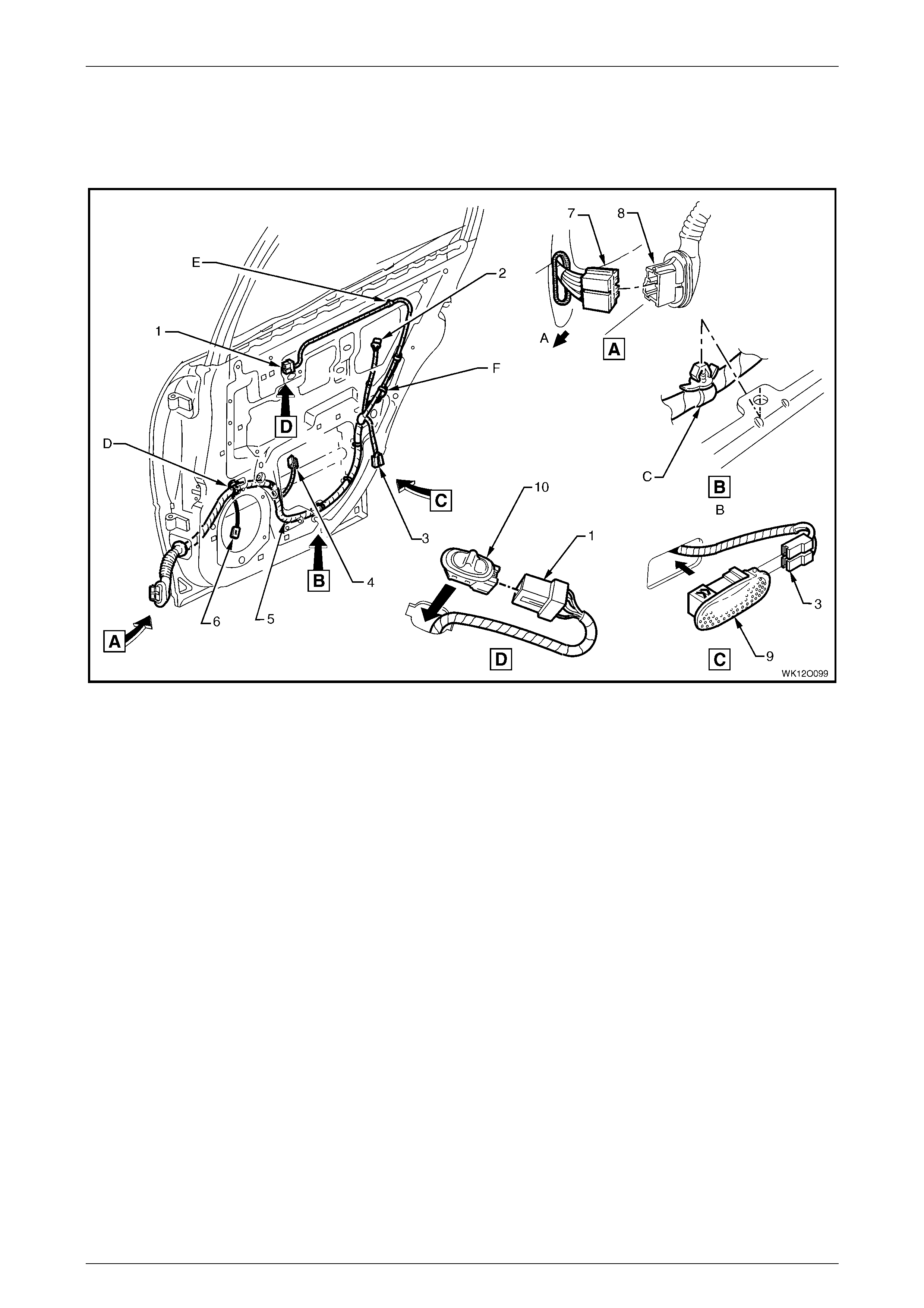
Fuses, Relays and Wi ring Harnesse s Page 12O–116
Page 12O–116
3.76 Door Wiring Harness – 3
Rear Door
Figure 12O – 94
Legend
1 Side Window Switch Connector (S221)
2 Rear Side Door Lock Act uator Connect or (Y 31)
3 Rear Side Door Courtesy Lamp Connect ors (E99)
4 Rear Side Door Window Regulator Connec t or (M14)
5 Door Wiring Harness
6 Radio Door Speaker Connect or (B117)
7 Body Wiring Harness to Right-hand Rear Door Wiring
Harness Connect or (X800)
8 Right-hand Rear Door W i ri ng Harness t o Body Wi ri ng
Harness Connect or (X800)
9 Rear Side Door Courtesy Lamp
10 Side Window Switch
A Front of vehicle.
B Typical (7 places).
C Door wiring harness clipped to inner door inner panel as
shown.
D Door wiring harness clipped to door inner panel.
E Rear door inner seal pierced and door wiring harness
clipped to inner panel (2 places).
F Courtesy lamp connector taped back ed when courtesy lamp
not fitted.
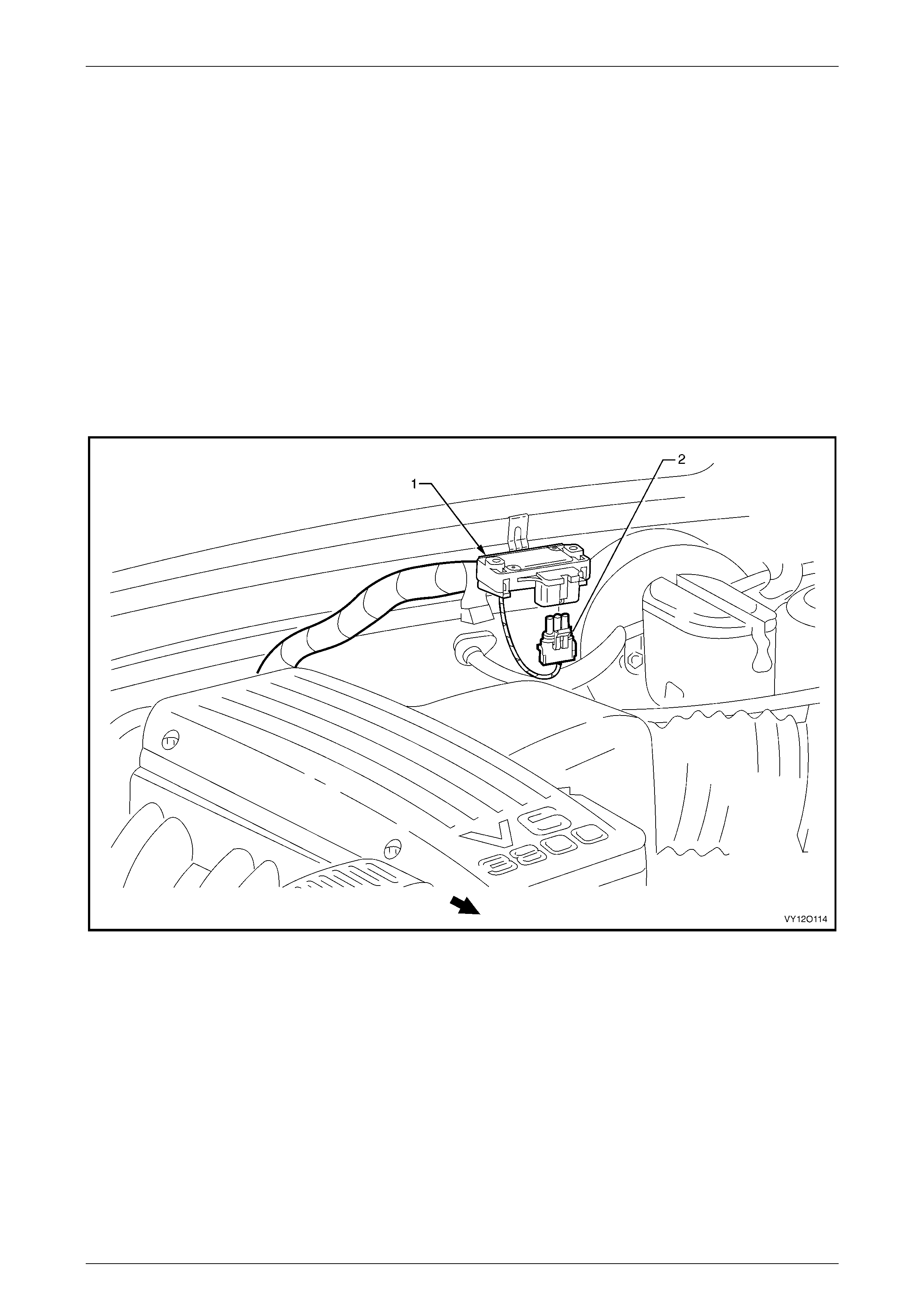
Fuses, Relays and Wi ring Harnesse s Page 12O–117
Page 12O–117
4 Wiring Installation Diagrams –
Left-hand Drive
The following figures illustrate the vehicle wiring installation diagrams for MY 2004 WK left-hand drive Sedan.
All Battery Harness and Powertrain Harness for left-hand drive vehicles carry over from the right-hand drive vehicles. For
information relating to the wiring harness installation diagrams for the left-hand drive Sedan not provided in this section,
refer to 3 Wiring Installation Diagrams – Right-hand Drive.
NOTE: Some of the following wiring installation diagrams illustrate the upper level harnesses which incorporate all
necessary wiring harness connectors for all production options. Depending on equipment level and vehicle model, some
of the connectors may be taped back to the harness when a particular option is not fitted, or the particular level of
harness fitted to the vehicle may not incorporate some of the connectors illustrated.
4.1 Main Wiring Harness – 1
Barometric Pressure Sensor
Figure 12O – 95
Legend
1 Barometric Pressure Sensor Assembly 2 Barometric Pressure Sensor Connector (B26)
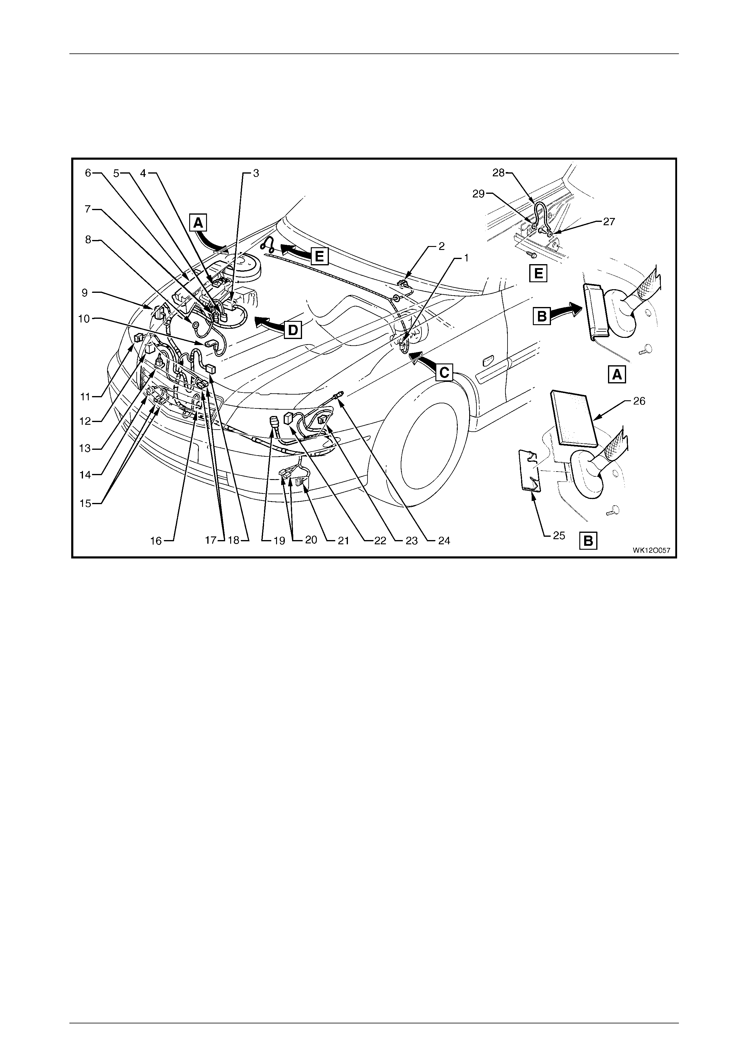
Fuses, Relays and Wi ring Harnesse s Page 12O–118
Page 12O–118
4.2 Main Wiring Harness – 2
Engine Compartment
Figure 12O – 96
Legend
1 Brake Pressure Differential Connector (S37)
2 Windshield Wiper Motor Connec t or (M17)
3 Electronic Braking and Traction Control Module Connector
(A37)
4 Cruise Control Connect or (A18)
5 Main Wiring Harness to Battery Wiring Harness Connec tor
(X106)
6 Engine Wiring Harness J u nct i on Connector (X100)
7 Front Wheel Speed Sensor Connector (B52 – R)
8 A.B.S. Brack et Connector (X119 – G3 – GP3)
9 Ground Connector (X157)
10 Fusible Link Supply Connect or (X86 – A)
11 Turn Signal Lamp Connector (E 76 – R)
12 Headlamp Connect or (E83 – R)
13 Windshield Wiper and Windshield Washer
Connector (M19)
14 Front Fog & Cornering Lamp Connector (X110)
15 Horn Connectors (B9 – R)
16 Ambient Air Temperature Sensor Connector (B 23)
17 Hood Theft Deterrent Connect ors (S135)
18 Engine Cooling Fan Connector (M7 – X1)
19 Main Wiring Harness to Powertrain Harness Connector
(X101)
20 Horn Connectors (B9 – L)
21 Front Fog & Cornering Lamp Connector (X111)
22 Headlamp Connect or (E83 – L)
23 Turn Signal Lamp Connector (E 76 – L)
24 Front Wheel Speed Sensor Connector (B52 – L)
25 Sealing Patch Grommet
26 Grommet Insert
27 Instrument Panel to Body Ground Strap Terminal
(X118 – GP9)
28 Body to Instrum ent Panel Ground Strap
29 Body to Instrument P anel Ground Strap Terminal
(X118 – GP10)
For views C and D, refer to 4.3 Main Wiring Harness – 3.
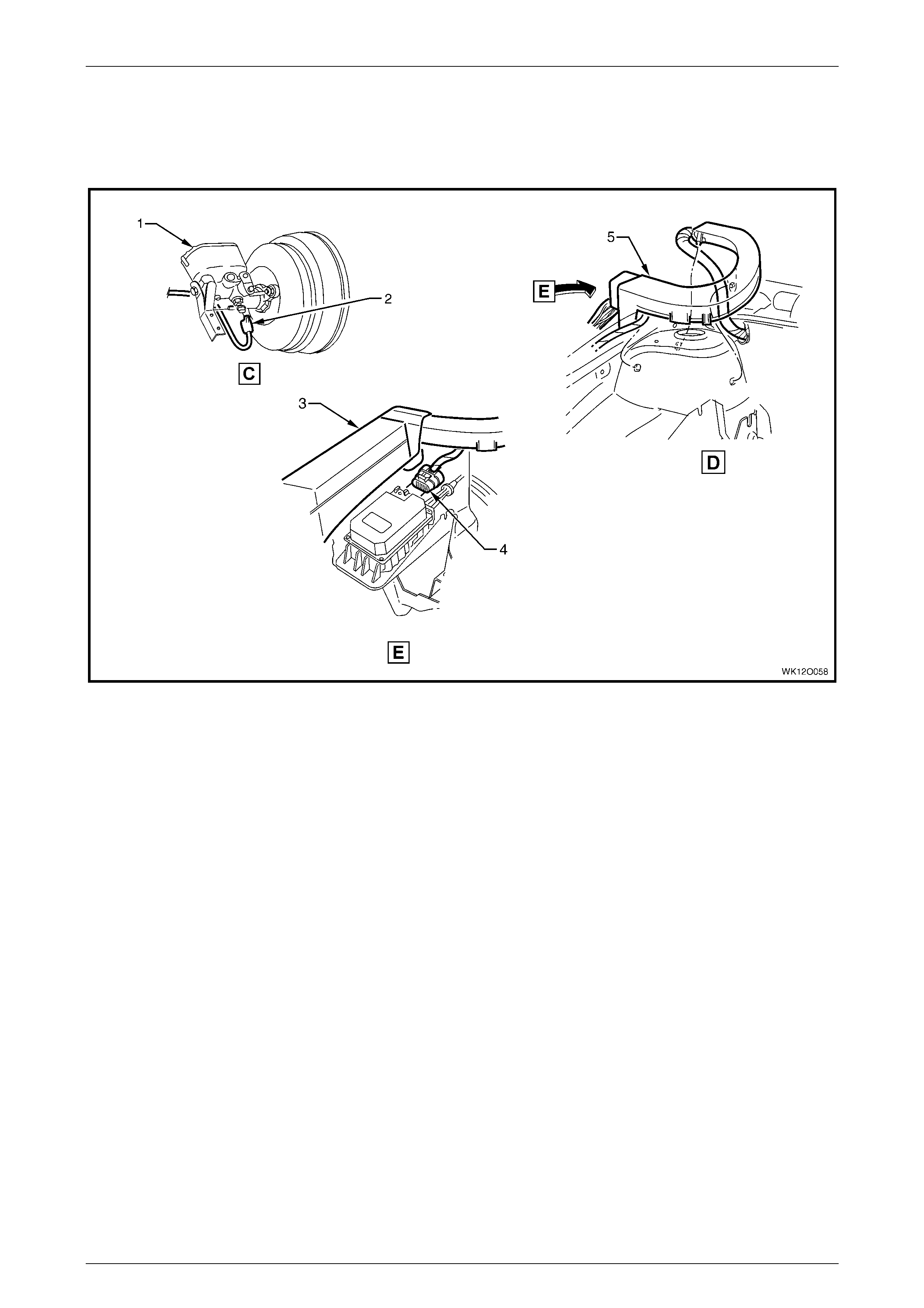
Fuses, Relays and Wi ring Harnesse s Page 12O–119
Page 12O–119
4.3 Main Wiring Harness – 3
Protector Assembly, Cruise Control and Engine Harness Connectors
Figure 12O – 97
Legend
1 Brake Master Cyl i nder and Brak e Boost er
2 Brake Pressure Differential Connector (S37)
3 Engine Wiring Harness Junction Connecter Cover
4 Cruise Control Connect or (A18)
5 Harness Former
For location of views C and D, refer to
4.2 Main Wiring Harness – 2.
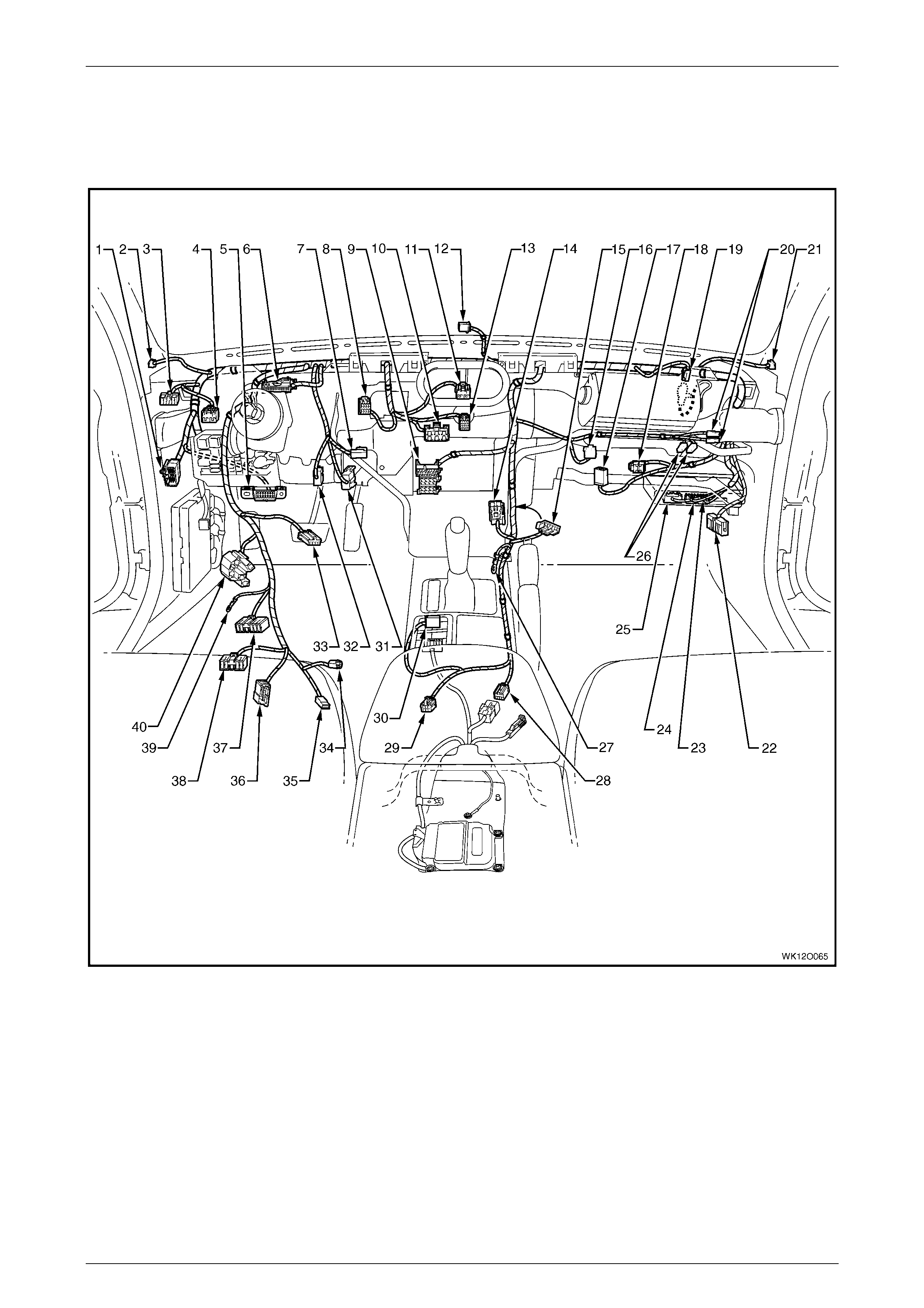
Fuses, Relays and Wi ring Harnesse s Page 12O–120
Page 12O–120
4.4 Main Wiring Harness – 4
Cockpit Module –Without Cruise Control
Figure 12O – 98

Fuses, Relays and Wi ring Harnesse s Page 12O–121
Page 12O–121
Legend
1 Main Wiring Harness to Powertrain Harness Connector
(X206)
2 Radio Front Speaker Dash Upper Connector (B 112)
3 Headlamp Automatic Control Switch Connect or (S125)
4 Fuel Filler Door Release Switch Connector (S191)
5 Wiring (Diagnostic) Connector (X40)
6 Instruments Connector (P3)
7 Stop Lamp, Traction and Cruise Control Release Switch
Connector (S 220 – X2)
8 Trip Odometer Reset Switch Connector (S237)
9 Radio, Clock and CD Player Connec tor (A133 – X1)
10 Heater and A/C Evaporator Module Connect or (A60 – X1)
11 Hazard Warning S witch Connector (S120)
12 Ambient Light Sensor Connect or (B55)
13 Heater and A/C Evaporator Module Connect or (A60 – X2)
14 Front Cigar Lighter Connect or (X113 – F)
15 Inline to Radio and Mobile Telephone Connector (X155)
16 Rear Compartment Lid Release Switc h Connector (S195)
17 Blower Motor Resist or Connector (R6 – LHD)
18 Main Wiring Harness to Body Wiring Harness Connect or
(X204)
19 Main Wiring Harness t o Pass enger Airbag Harness
Connector (X205)
20 Instrument P anel Compartment Lamp Switch Connectors
(S142)
21 Radio Front Speaker Dash Upper Connector (B 112)
22 Main Wiring Harness to Body Wiring Harness Connect or
(X200)
23 Body Control Module Connect or (A15 – X3)
24 Body Control Module Connect or (A15 – X2)
25 Body Control Module Connect or (A15 – X1)
26 Instrument P anel Compartment Lamp Connectors (E82)
27 Radio Ground Terminal (X118 – GP8)
28 Main Wiring Harness to Body Wiring Harness Connect or
(X303)
29 Main Wiring Harness t o Consol e Wiring Harness Connector
(X309)
30 Main Wiring Harness to Transmission Selector Harness
Connector (X301)
31 Stop Lamp, Traction and Cruise Control Release Switch
Connector (S 220 – X1)
32 Stop Lamp, Traction and Cruise Control Release Switch
Connector (S 220 – X3)
33 Cruise Control Switc h Connect or (S43)
34 Igniti on Lock Cyl i nder Bulb Connect or (E30)
35 Igniti on and Start Switch Connect or (S149 – X2)
36 Steering Wheel Clock Spring Coil Connector (X116)
37 Turn Signal and Headlamp Switch Connector (S231)
38 Windshield Wiper and Washer Switch Connector (S247)
39 Ignition and Start Switch Terminal (S149 –GP15 – X3)
40 Igniti on and Start Switch Connect or (S149 – X1)
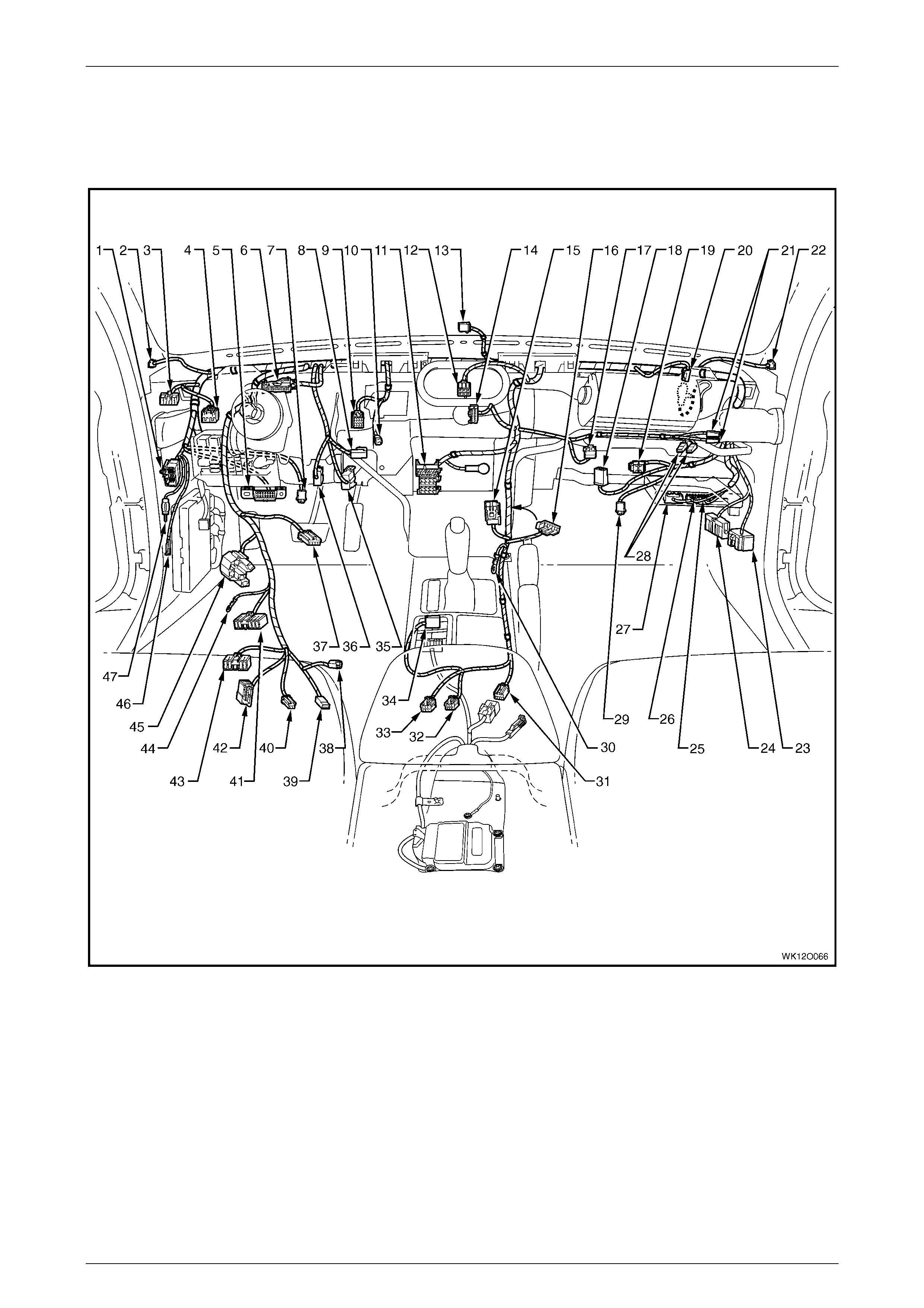
Fuses, Relays and Wi ring Harnesse s Page 12O–122
Page 12O–122
4.5 Main Wiring Harness – 5
Cockpit Module –With Cruise Control
Figure 12O – 99

Fuses, Relays and Wi ring Harnesse s Page 12O–123
Page 12O–123
Legend
1 Main Wiring Harness to Powertrain Harness Connector
(X206)
2 Radio Front Speaker Dash Upper Connector (B 112)
3 Headlamp Automatic Control Switch Connect or (S125)
4 Fuel Filler Door Release Switch Connector (S191)
5 Wiring (Diagnostic) Connector (X40)
6 Instruments Connector (P3)
7 Step Well Lamp Connector (E105)
8 Stop Lamp, Traction and Cruise Control Release Switch
Connector (S 220 – X2)
9 Trip Odometer Reset Switch Connector (S237)
10 Inside Air Temperature Sensor Connect or (B59)
11 Radio, Clock and CD Player Connec tor (A133 – X1)
12 Hazard Warning S witch Connector (S120) [Level 1 only]
13 Ambient Light Sensor Connect or (B55)
14 Blower Motor and A/C Comp ressor Connec tor (A14 – X2)
15 Front Cigar Lighter Connect or (X113 – F)
16 Inline to Radio and Mobile Telephone Connector (X155)
17 Rear Compartment Lid Release Switc h Connector (S195)
18 Blower Motor Resist or Connector (R6 – LHD)
19 Main Wiring Harness to Body Wiring Harness Connect or
(X204)
20 Main Wiring Harness t o Pass enger Air Bag Harness
Connector (X205)
21 Instrument P anel Compartment Lamp Switch Connector
(S142)
22 Radio Front Speaker Dash Upper Connector (B 112)
23 Main Wiring Harness to Body Wiring Harness Connect or
(X201)
24 Main Wiring Harness to Body Wiring Harness Connect or
(X200)
25 Body Control Module Connect or (A15 – X3)
26 Body Control Module Connect or (A15 – X2)
27 Body Control Module Connect or (A15 – X1)
28 Instrument P anel Compartment Lamp Connector (E82)
29 Step Well Lamp Connector (E105)
30 Radio Ground Terminal (X118 – GP8)
31 Main Wiring Harness to Body Wiring Harness Connect or
(X303)
32 Hazard Warning S witch Connector (S120)
33 Side Air Bag Harness to Body Wiring Harness Connector
(X307)
34 Main Wiring Harness to Transmission Selector Harness
Connector (X301)
35 Stop Lamp, Traction and Cruise Control Release Switch
Connector (S 220 – X1)
36 Stop Lamp, Traction and Cruise Control Release Switch
Connector (S 220 – X3)
37 Igniti on Lock Cyl i nder Bulb Connect or (E30)
38 Cruise Control Switc h Connect or (S43)
39 Igniti on and Start Switch Connect or (S149 – X2)
40 Windshiel d Wiper Dwell Module Connect or (R23)
41 Turn Signal and Headlamp Switch Connector (S231)
42 Steering Wheel Clock Spring Coil Connector (X116)
43 Windshield Wiper and Washer Switch Connector (S247)
44 Ignition and Start Switc h Terminal (S149 – GP15 – X3)
45 Igniti on and Start Switch Connect or (S149 – X1)
46 Radio Antenna Amplif i er Connect or (N3)
47 Radio Power Antenna Connector (W6 – X2)
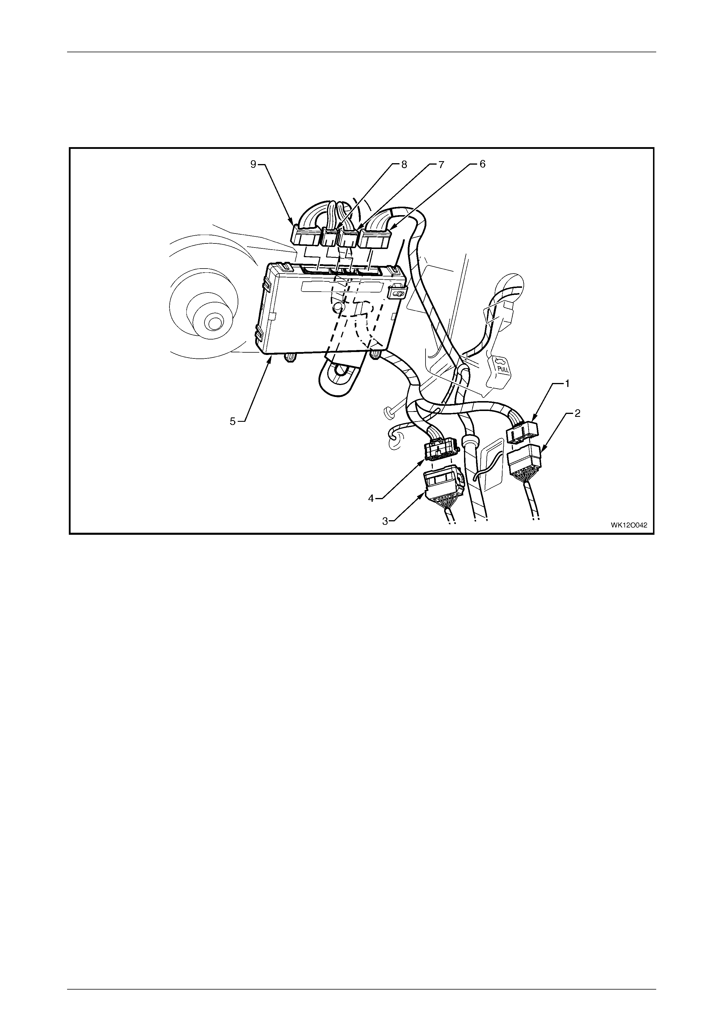
Fuses, Relays and Wi ring Harnesse s Page 12O–124
Page 12O–124
4.6 Main Wiring Harness – 6
Cockpit Module
Figure 12O – 100
Legend
1 Main Wiring Harness To Body Wiring Harness Connector
(X201)
2 Body Wiring Harness To Main Wiring Harness Connec tor
(X201)
3 Body Wiring Harness To Main Wiring Harness Connec tor
(X200)
4 Main Wiring Harness To Body Wiring Harness Connector
(X200)
5 Body Control Module
6 Body Control Module Connect or (A15 – X4)
7 Body Control Module Connect or (A15 – X3)
8 Body Control Module Connect or (A15 – X2)
9 Body Control Module Connect or (A15 – X1)
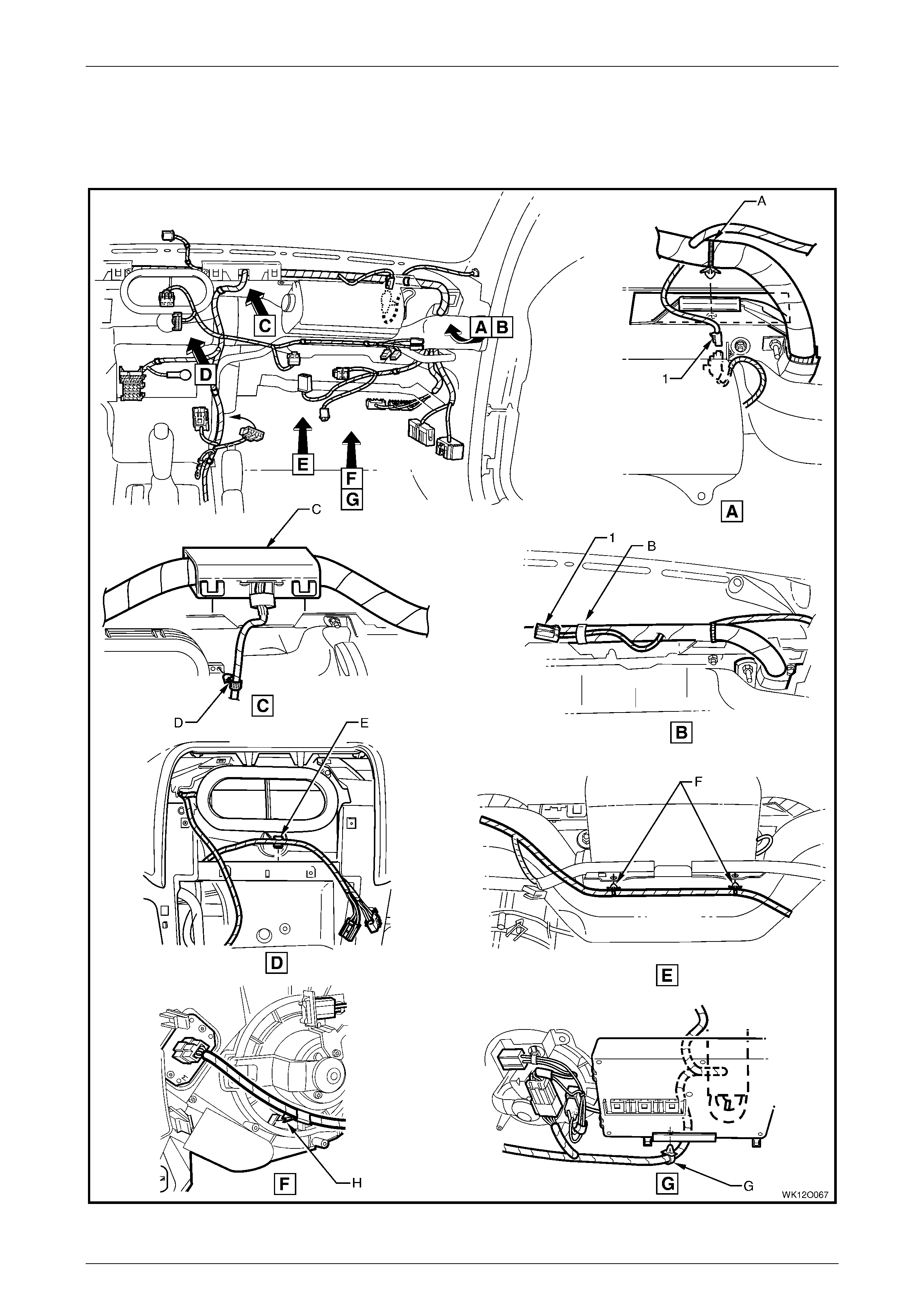
Fuses, Relays and Wi ring Harnesse s Page 12O–125
Page 12O–125
4.7 Main Wiring Harness – 7
Cockpit Module
Figure 12O – 101

Fuses, Relays and Wi ring Harnesse s Page 12O–126
Page 12O–126
Legend
1 Main Wiring Harness to Passenger Air Bag Harness
Connector (X205) A Harness ret ainer attached to instrument panel cover
assembly as shown – vehicles with passenger air bag.
B Passengers si de air bag connector taped back as s hown –
vehicles without passengers side air bag connector.
C Harness former att ached t o inst rum ent panel cover
assembly (2 places ) as shown.
D Harness attached to heating, ventilation & A/C unit as
shown.
E W iring harness attached to heating, ventilation and A/C
assembly.
F Wiring harness attached to passenger side airbag support
rail assem bl y as shown.
G Harness attached to body control m odul e support brack et as
shown.
H Harness attached t o heati ng, vent ilat i on and A/ C assembl y
as shown.
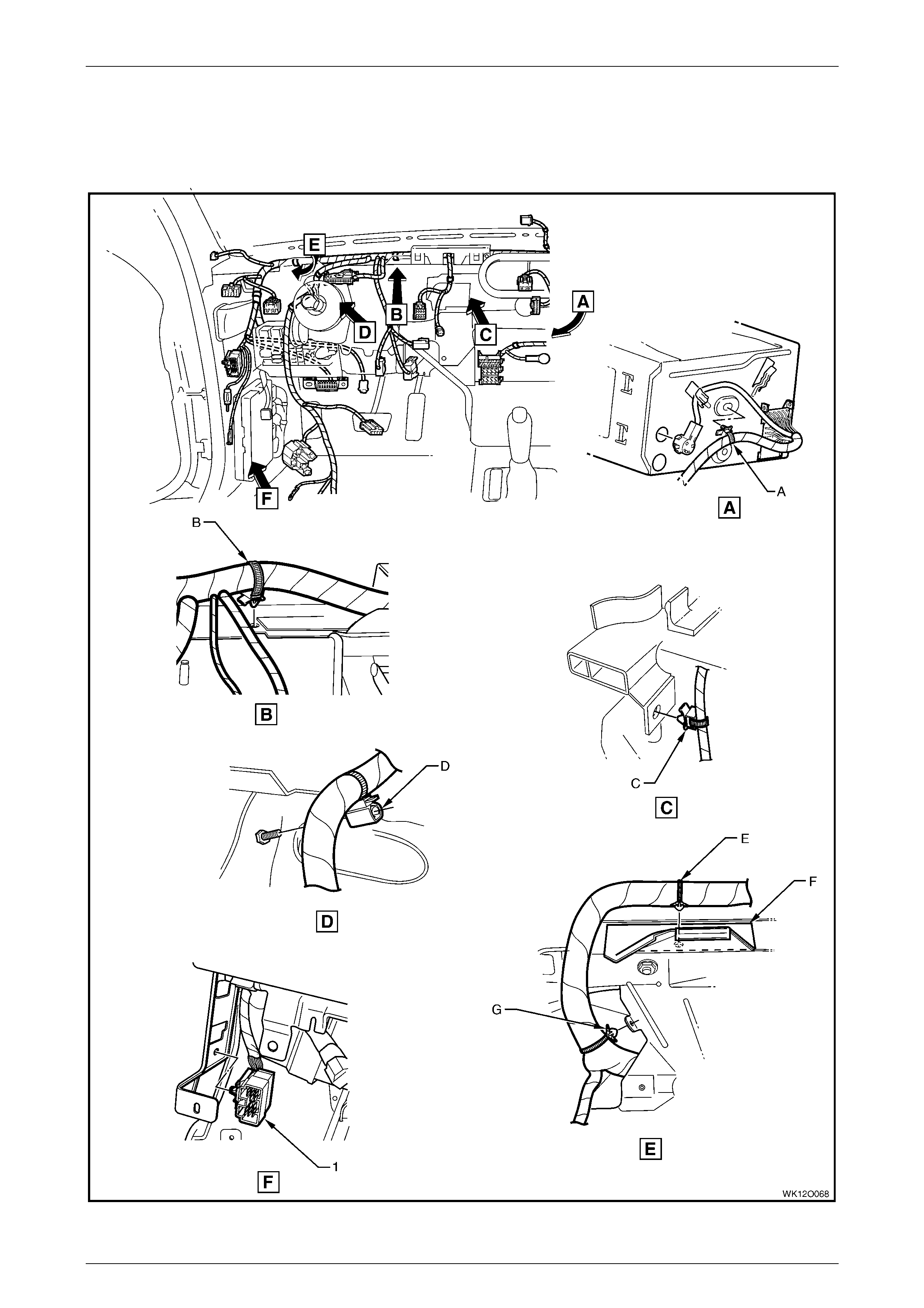
Fuses, Relays and Wi ring Harnesse s Page 12O–127
Page 12O–127
4.8 Main Wiring Harness – 8
Cockpit Module
Figure 12O – 102

Fuses, Relays and Wi ring Harnesse s Page 12O–128
Page 12O–128
Legend
1 Main Wiring Harness to Powertrain Harness Connector
(X206) A Main wiring harness attached to instrument panel cover
assembly as shown.
B Harness attached to vehicle as shown.
C Main wiring harness attached to instrument panel cover
assembly as shown.
D Main wiring harness attached to instrument panel cover
assembly as shown.
E Instrum ent panel cover assembly.
F Main wiring harness att ached to inst rum ent panel cover
assembly as shown.
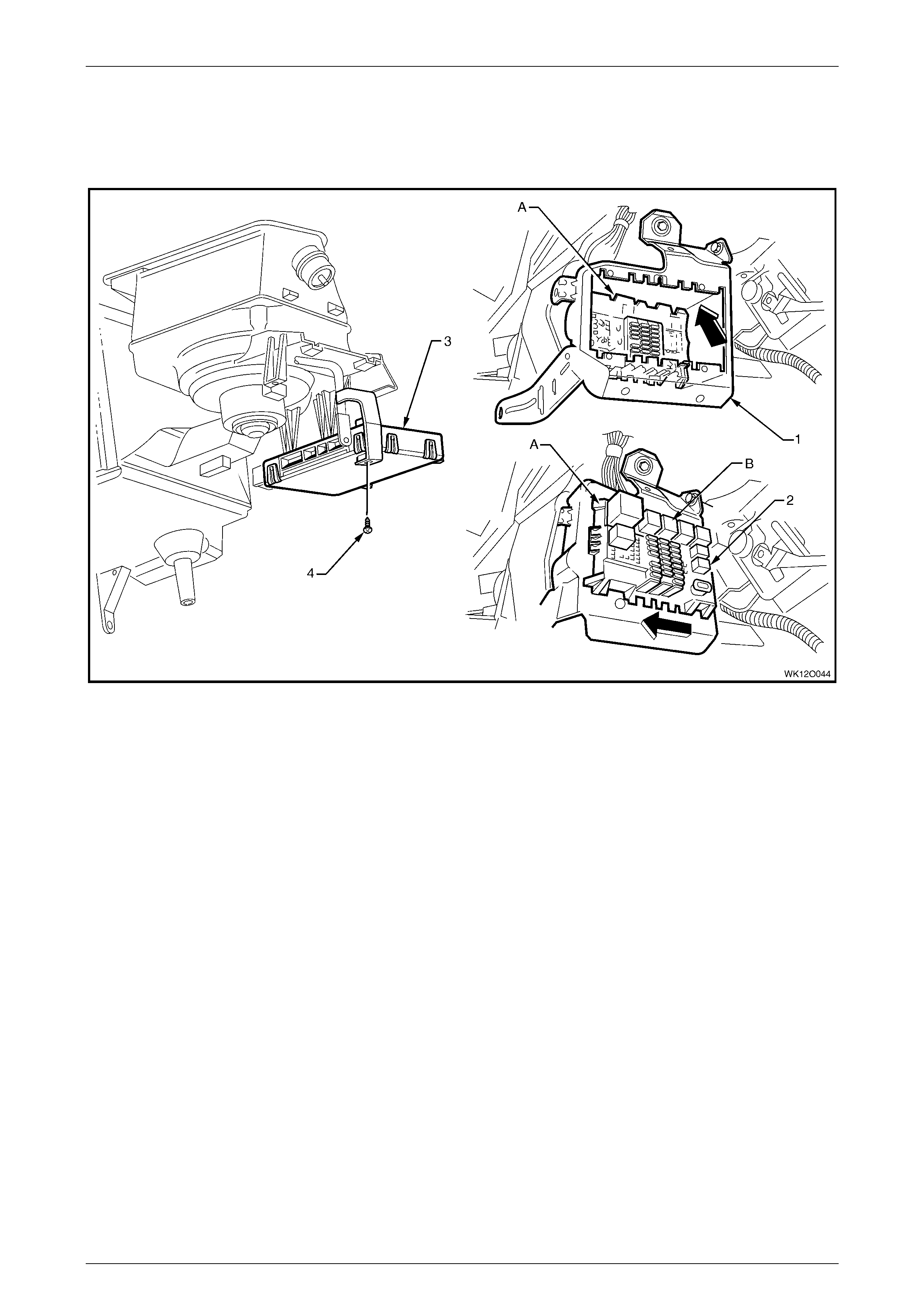
Fuses, Relays and Wi ring Harnesse s Page 12O–129
Page 12O–129
4.9 Main Wiring Harness – 9
Fuse & Relay Panel and Body Control Module
Figure 12O – 103
Legend
1 Instrument P anel Wiring Harness Fuse Block Mounting
Bracket
2 Instrument P anel Wiring Harness Fuse Block (X129)
3 Body Control Module
4 Attachi ng Screw, Body Control Module Mounting to Support
A Instrument panel wiring harnes s fuse block install ed as
shown.
B For installa tion of relays, fuses and circuit breakers, refer to
1 General Information.
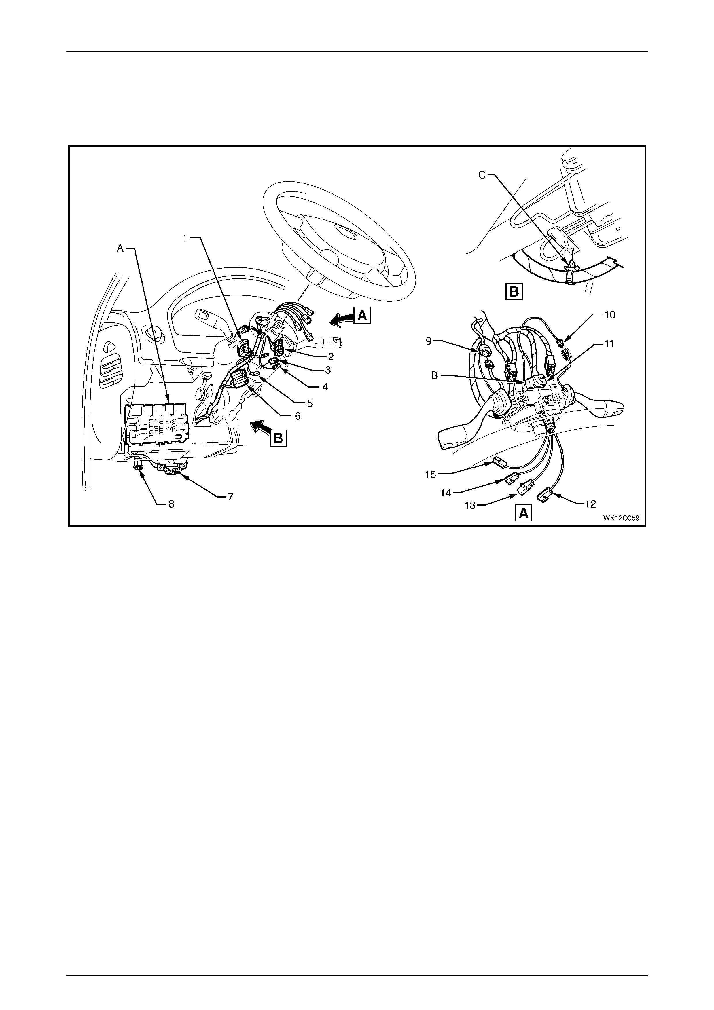
Fuses, Relays and Wi ring Harnesse s Page 12O–130
Page 12O–130
4.10 Main Wiring Harness – 10
Steering Column
Figure 12O – 104
Legend
1 Turn Signal Switch Connector (S231 – X1)
2 Windshield Wiper/W asher Switch Connector (S247)
3 Igniti on Lock Cylinder Bulb Connector (E30)
4 Igniti on and Start Switch Connect or (S149 – X2)
5 Ignition and Start Switc h Terminal (S149 – X3)
6 Igniti on and Start Switch Connect or (S149 – X1)
7 Wiring (Diagnostic) Connector (X40)
8 Stepwell Lamp Connect or (E 105)
9 Cruise Control Switc h Connect or (S43)
10 Windshiel d Wiper Dwell Module Connect or (R23)
11 Steering Wheel Lock Cl ock Spring Coil Connector (X116)
12 Steering Wheel Horn Connector (S7)
13 Steering Wheel Inflator Restraint Module Connector (A106)
14 Radio Control S witch Connect or (S208 – X2)
15 Radio Control S witch Connect or (S208 – X1)
A For fuse and relay panel – instrument panel wiring harnes s
fuse block (X129) inst al l ati on, ref er to
4.9 Main Wiring Harness – 9.
B Clock s pri ng coil connecto r i nst al l ed and secured by l ocking
retainer in direction of arrow shown.
C Main wiring harness attached to steering column as shown.
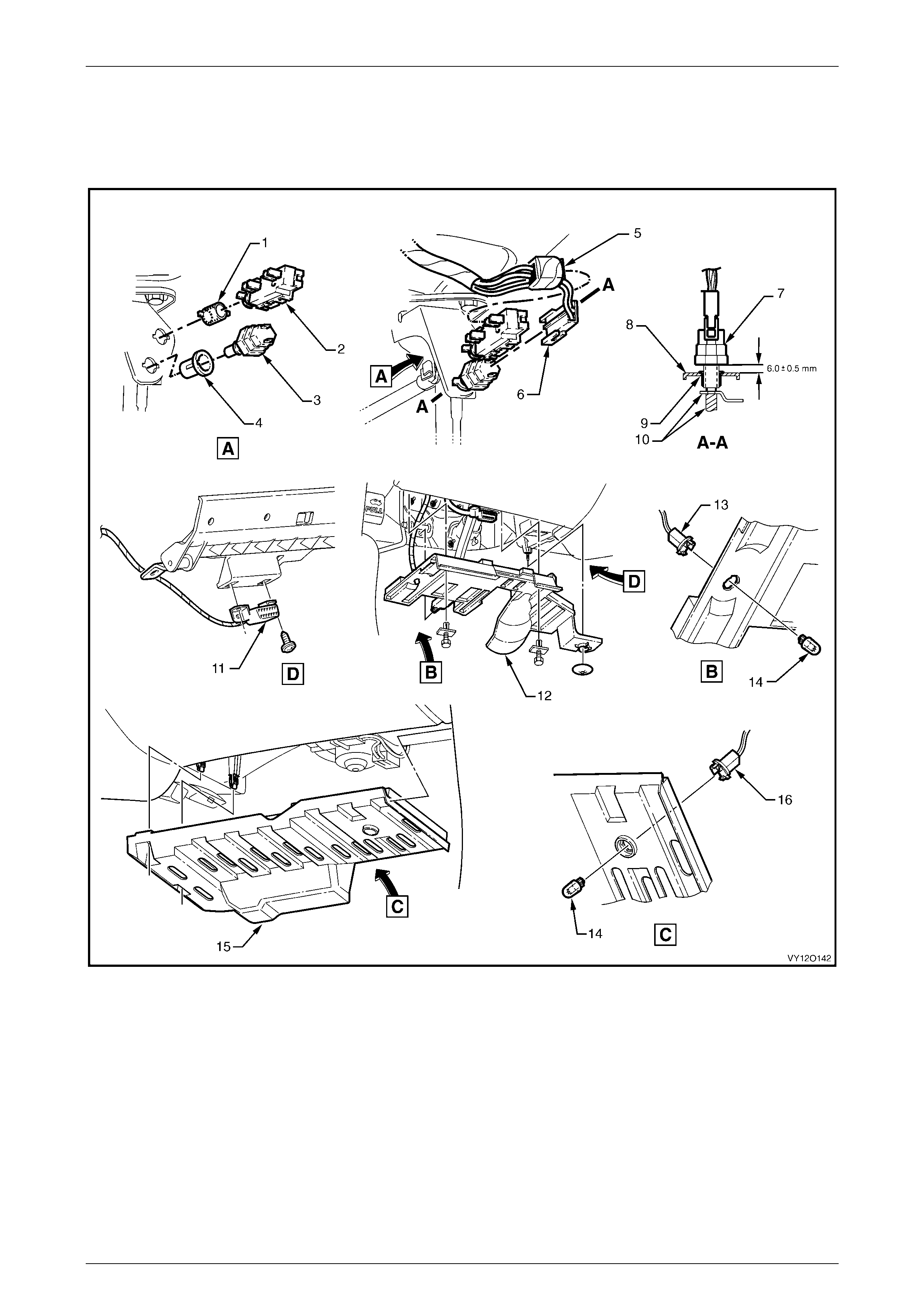
Fuses, Relays and Wi ring Harnesse s Page 12O–131
Page 12O–131
4.11 Main Wiring Harness – 11
Cruise Control, Stop Lamp Switches, Data Link Connector & Stepwell Lamps
Figure 12O – 105
Legend
1 Nut
2 Cruise Control Rel ease Switc h
3 Stepwell Lamp Switch
4 Nut
5 Stop Lamp, Traction & Cruise Control Releas e Switc h
Connector (S 220 – X2)
6 Stop Lamp, Traction & Cruise Control Releas e Switc h
Connector (S 220 – X1)
7 Stop Lamp Switch
8 Support Bracket
9 Nut
10 Pedal Assembly
11 Wiring (Diagnostic) Connector (X40)
12 Instrument P anel Lower Cover – Left-hand Side
13 Stepwell Lamp Connect or (E 105)
14 Stepwell Lamp
15 Instrument P anel Lower Cover – Right-hand S ide
16 Stepwell Lamp Connect or (E 105)
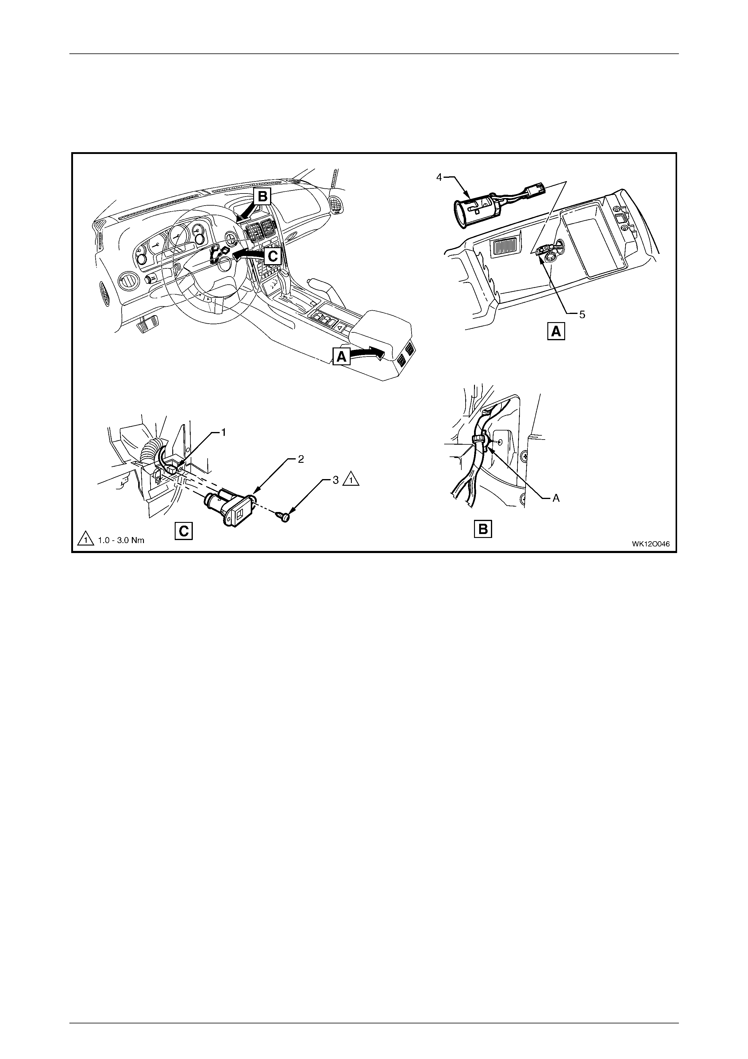
Fuses, Relays and Wi ring Harnesse s Page 12O–132
Page 12O–132
4.12 Main Wiring Harness – 12
Inside Air Temperature Sensor & Accessory Jack
Figure 12O – 106
Legend
1 Inside Air Temperature Sensor Connect or (B59)
2 Inside Air Temperature Sensor
3 Inside Air Temperature Sensor Attaching Screw
4 Accessory Power Socket
5 Access ory Power Socket Connector (X112)
A W iring harness attached to instrument panel as shown.
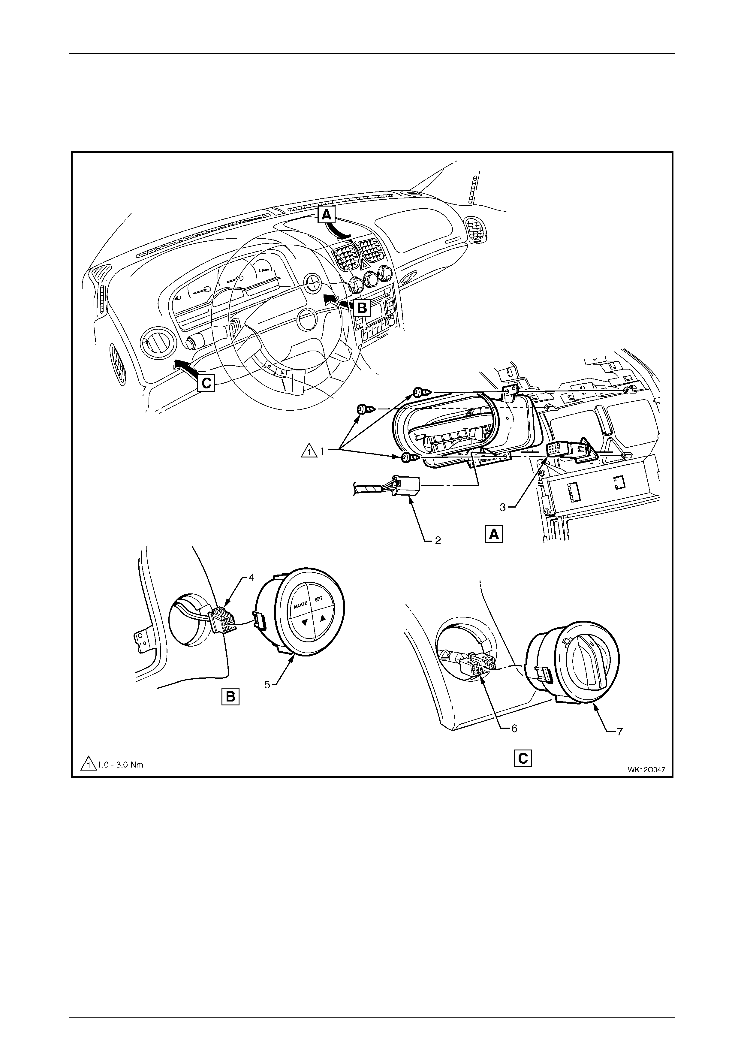
Fuses, Relays and Wi ring Harnesse s Page 12O–133
Page 12O–133
4.13 Main Wiring Harness – 13
Instrument Panel Facia Trim Swit ches – Level 1
Figure 12O – 107
Legend
1 Attaching Screws
2 Hazard Warning S witch Connector (S120)
3 Hazard Warning Switch
4 Trip Odometer Reset Switch Connector (S237)
5 Trip Odometer Reset Switch
6 Headlamp Automatic Control Switch Connect or (S125)
7 Headlamp Automatic Control Switch
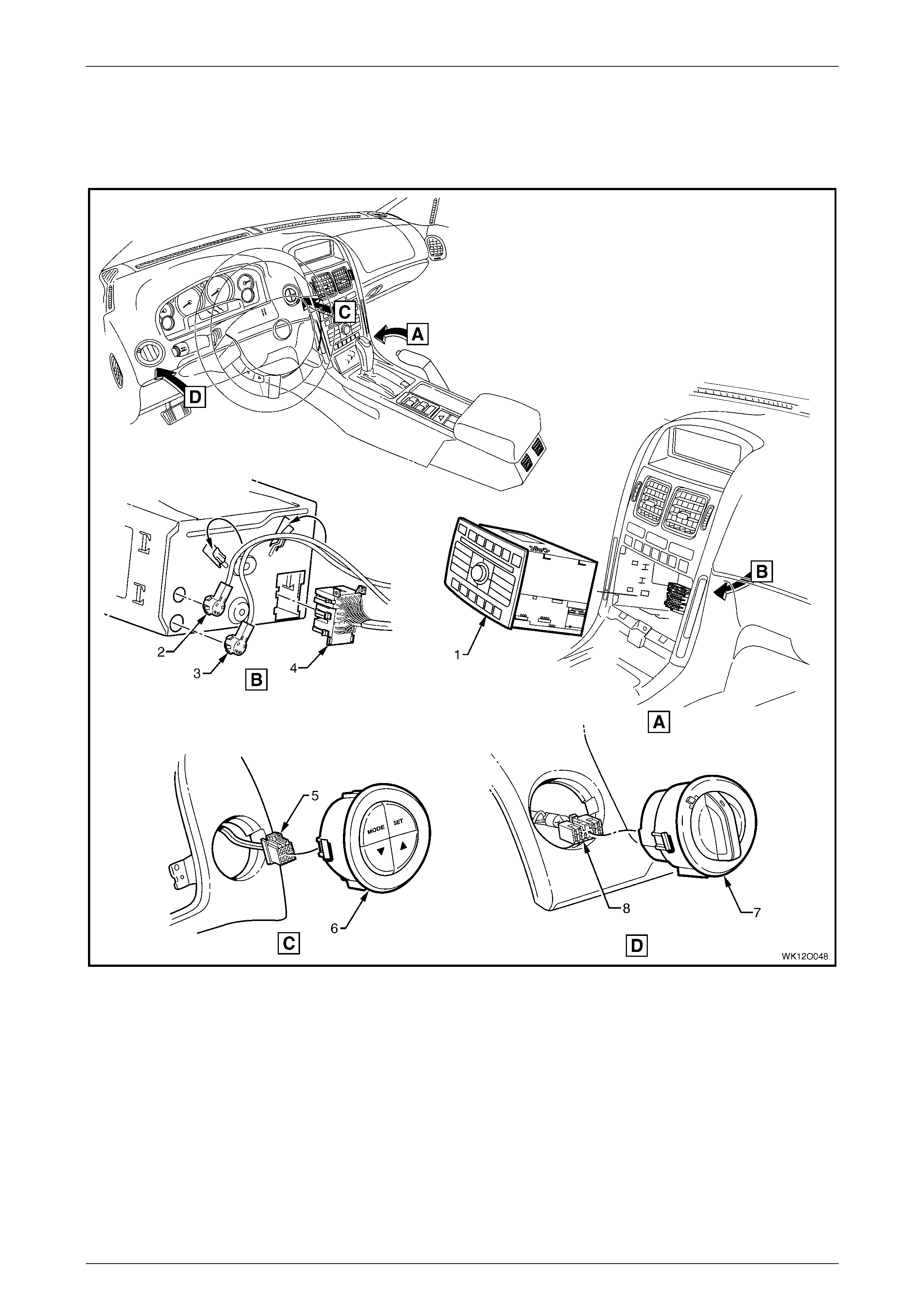
Fuses, Relays and Wi ring Harnesse s Page 12O–134
Page 12O–134
4.14 Main Wiring Harness – 14
Radio Assembly and Instrument Panel Facia Trim Switches and Connectors – Level 2, 3 & 5
Figure 12O – 108
Legend
1 Radio, Clock and CD Player As sembly
2 Diversit y Antenna Connector (A133 – X3)
3 Power Antenna Connect or (A133 – X2)
4 Radio, Clock and CD Player Connec tor (A133 – X1)
5 Trip Odometer Reset Switch Connector (S237)
6 Trip Odometer Reset Switch
7 Headlamp Automatic Control Switch
8 Headlamp Automatic Control Switch Connect or (S125)

Fuses, Relays and Wi ring Harnesse s Page 12O–135
Page 12O–135
4.15 Main Wiring Harness – 15
Passenger Side Airbag Wiring
Figure 12O – 109
Legend
1 Main Wiring Harness t o Pass enger Air Bag Harness
Connector (X205) A Harness ret ainer attached to instrument panel cover
assembly as shown – vehicles with passenger air bag.
B Passengers si de air bag connector taped back as s hown –
vehicles without passengers side air bag connector.
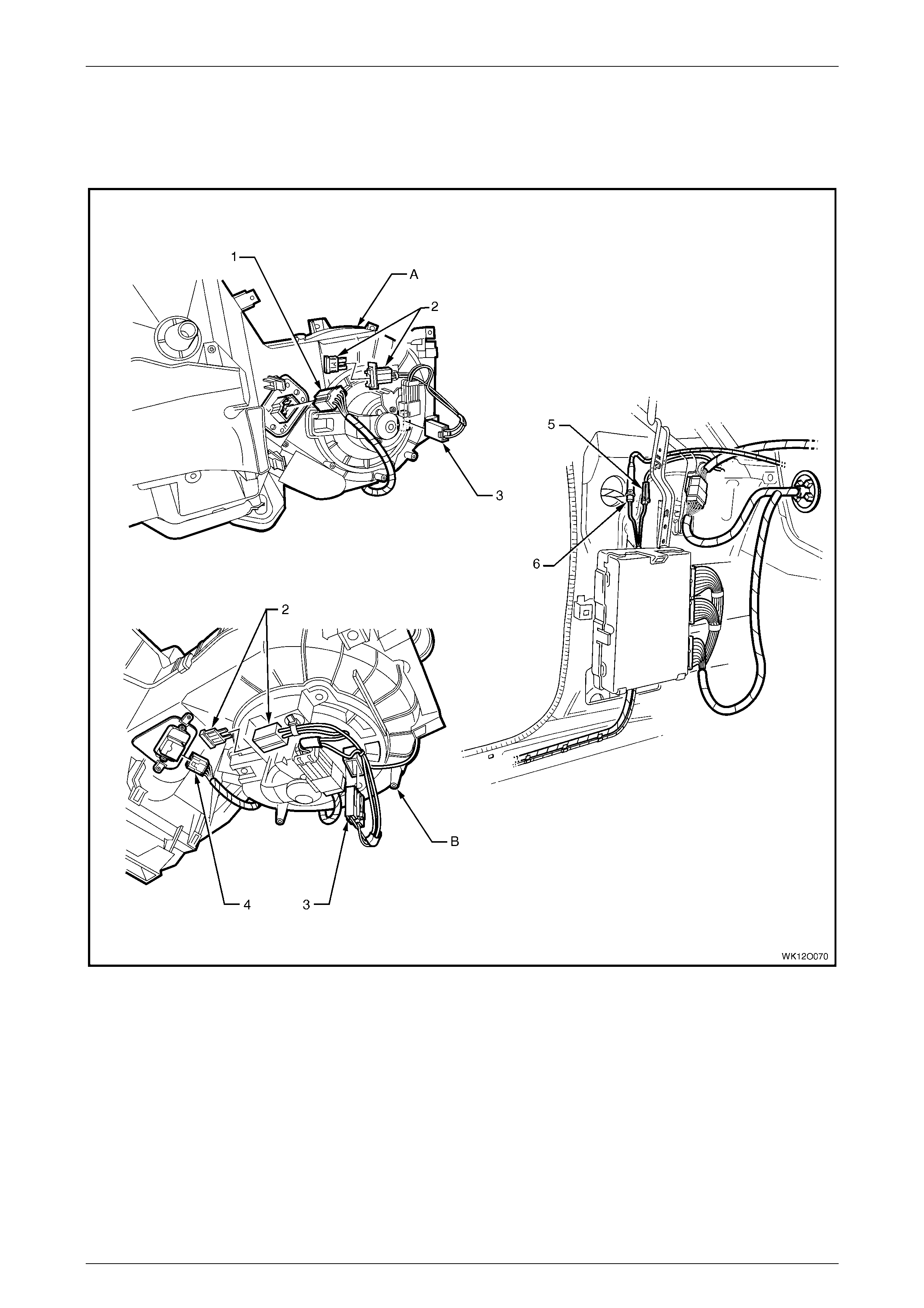
Fuses, Relays and Wi ring Harnesse s Page 12O–136
Page 12O–136
4.16 Main Wiring Harness – 16
Ampl i f ier Assembly Radio Antenna, Heati ng, Ventil ation & Air-conditioner Connectors
Figure 12O – 110
Legend
1 Blower Motor Resist or Connector (R6 – LHD)
2 Fuseblock Connector (X126 – LHD)
3 Blower Motor Connector (M3 – LHD)
4 Blower & Air Inlet Connect or (A 13 – LHD)
5 Radio Antenna Connect or (W6)
6 Radio Antenna Amplif i er Connect or (N3)
A Manual air-conditi oni ng bl ower unit shown.
B Auto climate control bl ower unit shown.
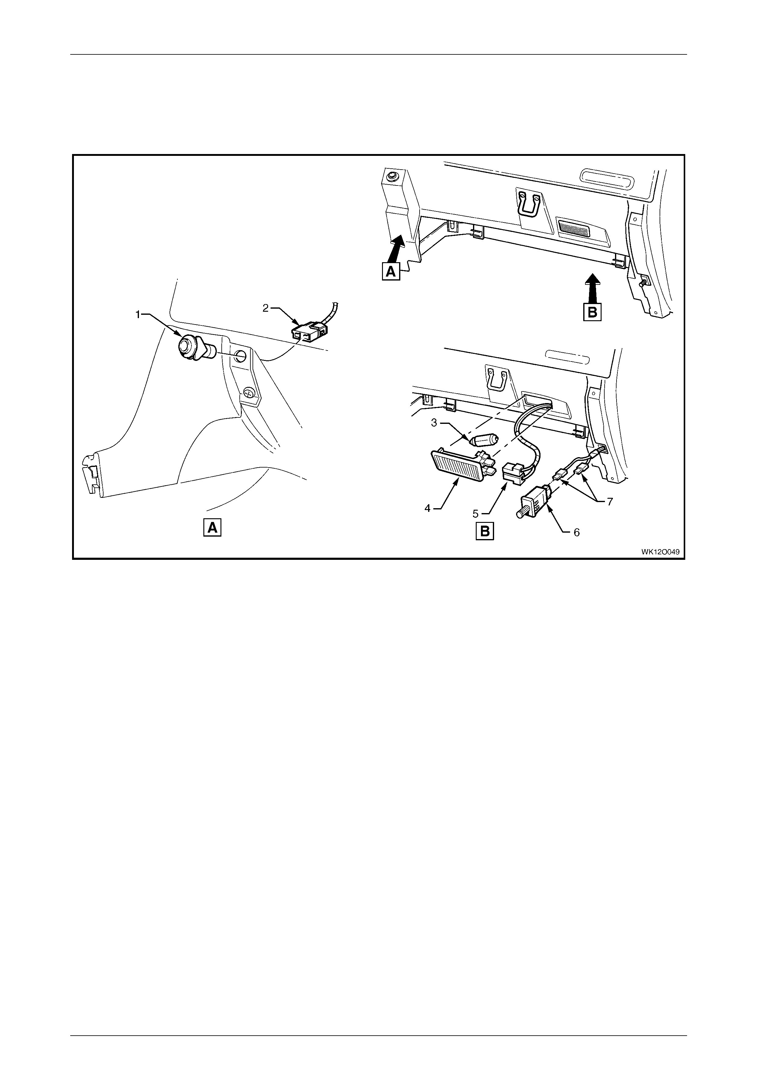
Fuses, Relays and Wi ring Harnesse s Page 12O–137
Page 12O–137
4.17 Main Wiring Harness – 17
Instrument Panel Compartment
Figure 12O – 111
Legend
1 Rear Compartment Lid Release Switc h
2 Rear Compartment Lid Release Connect or (S 195)
3 Instrument P anel Compartment Lamp Bulb
4 Instrument P anel Compartment Lamp
5 Instrument P anel Compartment Lamp Connectors (E82)
6 Instrument P anel Compartment Lamp Switch
7 Instrument P anel Compartment Lamp Switch Connectors
(S142)
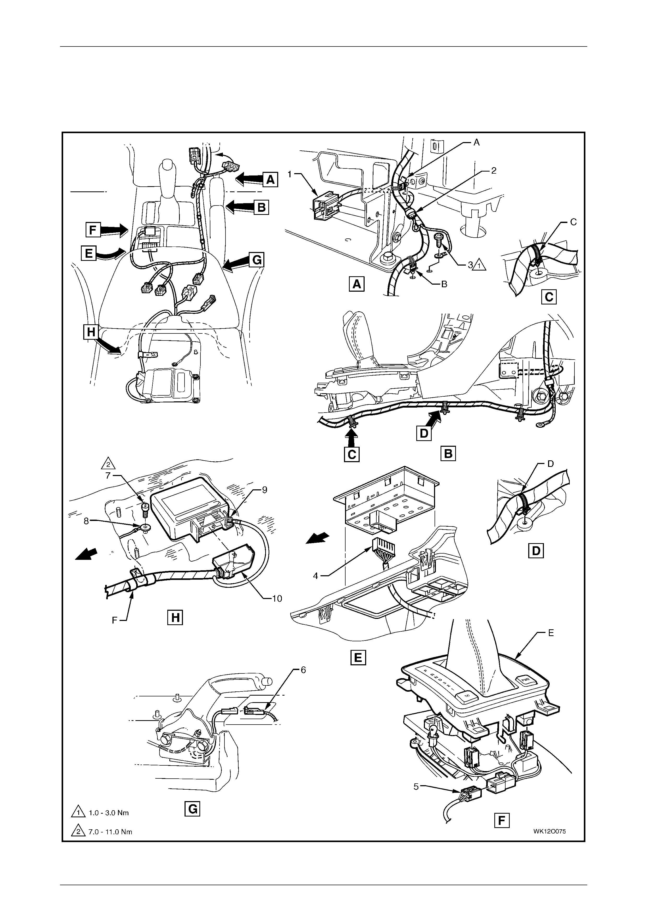
Fuses, Relays and Wi ring Harnesse s Page 12O–138
Page 12O–138
4.18 Main Wiring Harness – 18
Transmission & SIR Sensing Diagnostic Module Connectors
Figure 12O – 112

Fuses, Relays and Wi ring Harnesse s Page 12O–139
Page 12O–139
Legend
1 Front Cigar Lighter Connect or (X113 – F)
2 Inlineto Radi o and Mobile Telephone Connect or (X155)
3 Radio Ground Terminal Attaching Screw
4 Side Window (Master) Switch Connector (S222)
5 Main Wiring Harness to Transmission Select or Harness
Connector (X301)
6 Park Brake Switc h Connect or (S181)
7 Body Wiring Harness Earth Terminal Attaching Screw
8 Ground Terminal (X118 – GP12)
9 Ground Terminal (X118 – GP11)
10 Inflation Restraint Sensor Control Connect or (A65)
A Harness attached t o lower radio brack et as shown.
B Harness attached to vehicle as shown.
C Main wiring harness att ached to tunnel as shown.
D Main wiring harness att ached to tunnel as shown.
E Automatic transmission selector as shown.
F Harness attached t o stud as shown.
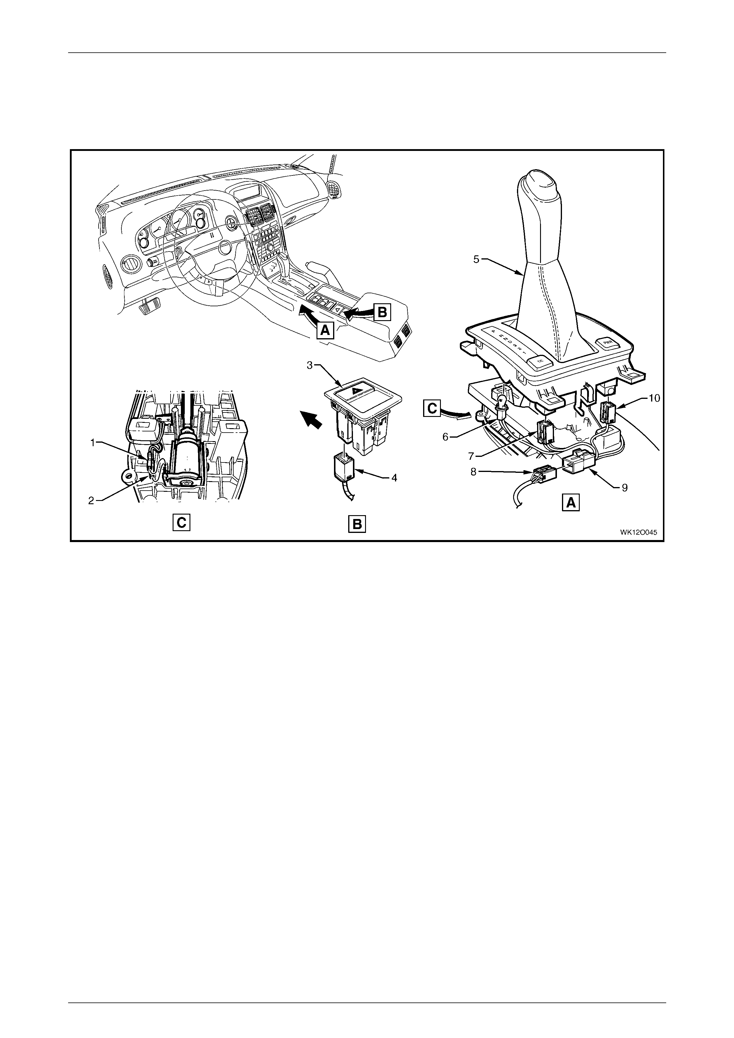
Fuses, Relays and Wi ring Harnesse s Page 12O–140
Page 12O–140
4.19 Main Wiring Harness – 19
Transmission Selector and Floor Console Connectors
Figure 12O – 113
Legend
1 Auto/Trans Shift Lock Park Terminal Connector (S21 – X2)
2 Auto/Trans Shift Lock Park Terminal Connector (S21 – X1)
3 Hazard Warning Switch
4 Hazard Warning S witch Connector (S120)
5 PRNDL Selector
6 Auto/Trans Control P ositi on Indicator Lamp Connector (E125)
7 Electroni c Tract i on Control S witch Connect o r (S 73)
8 Main Wiring Harness to Transmission Select or Harness
Connector (X301)
9 Transmission Selector Harness to Main Wiring Harness
Connector (X301)
10 Auto/Trans Shift Program Connector (S22)
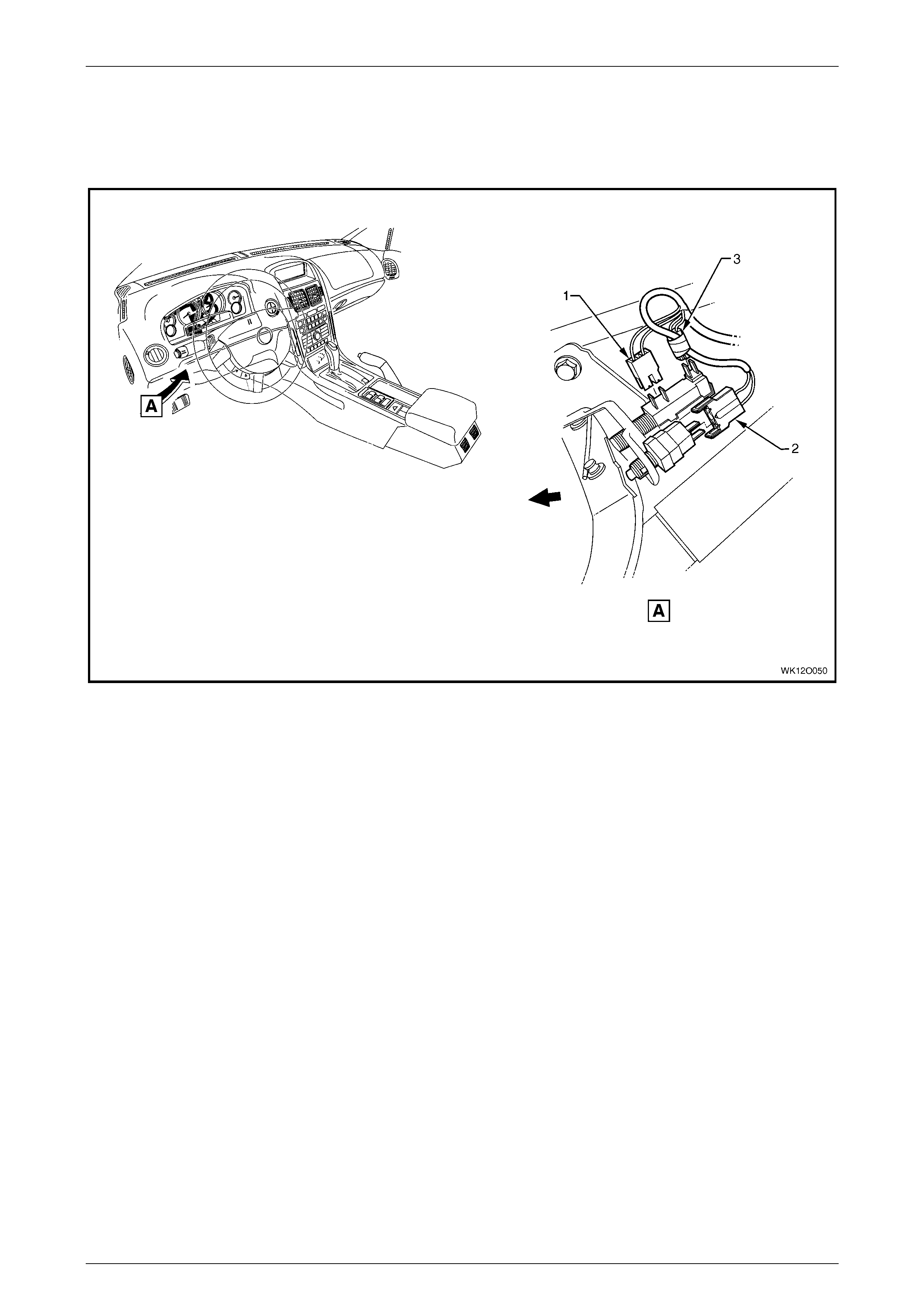
Fuses, Relays and Wi ring Harnesse s Page 12O–141
Page 12O–141
4.20 Main Wiring Harness – 20
Stop Lamp, Traction and Cruise Control Release Connectors
Figure 12O – 114
Legend
1 Stop Lamp, Traction & Cruise Control Releas e Switc h
Connector (S 220 – X3)
2 Stop Lamp, Traction & Cruise Control Releas e Switc h
Connector (S 220 – X1)
3 Stop Lamp, Traction & Cruise Control Releas e Switc h
Connector (S 220 – X2)
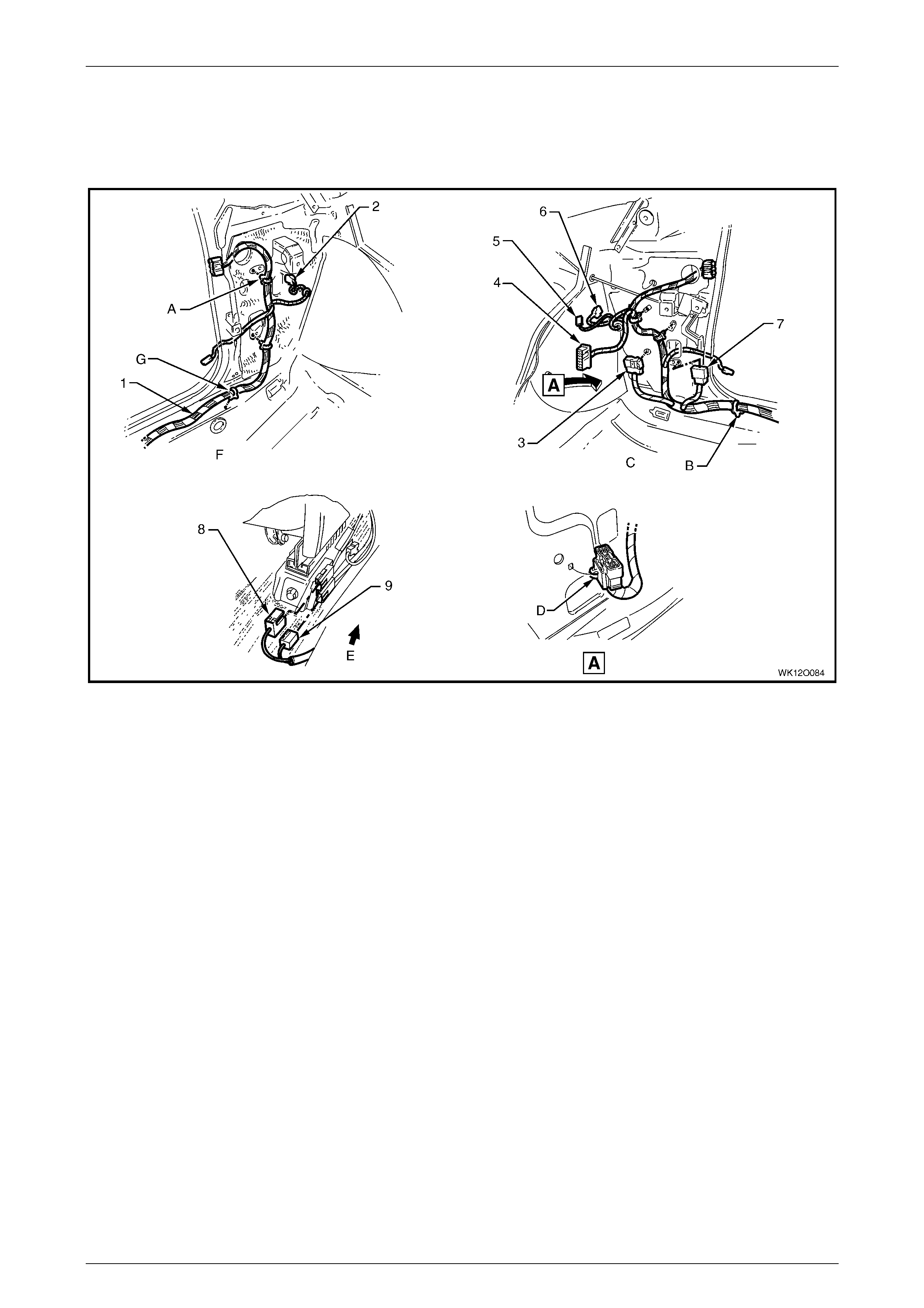
Fuses, Relays and Wi ring Harnesse s Page 12O–142
Page 12O–142
4.21 Body and Roof Wiring Harnesses – 1
Interior
Figure 12O – 115
Legend
1 Body Wiring Harness
2 Front Side Turn Lamp Connector (E75)
3 Body Wiring Harness to Main Wi ring Harness Connector
(X200)
4 Body Control Module Connect or (A15 – X4)
5 Radio Power Antenna Connector (W6 – X1)
6 Front Side Turn Lamp Connector (E75)
7 Body Wiring Harness to Main Wi ring Harness Connector
(X201)
8 Body Wiring Harness to Side Airbag Harness Connector
(X306 – LH) (X307 – RH)
9 Seat Belt Connector (Y 128 – LH) (Y129 – RH)
A Attach body wiring harness to shroud side panel (2 places).
B Body wiring harness att ached t o under body as shown
(9 places).
C Right-hand side shown.
D Main wiring harness connector clipped to shroud side panel
as shown.
E Front of vehicle.
F Left-hand side shown.
G B ody wiring harnes s attached to under body as shown
(6 places).
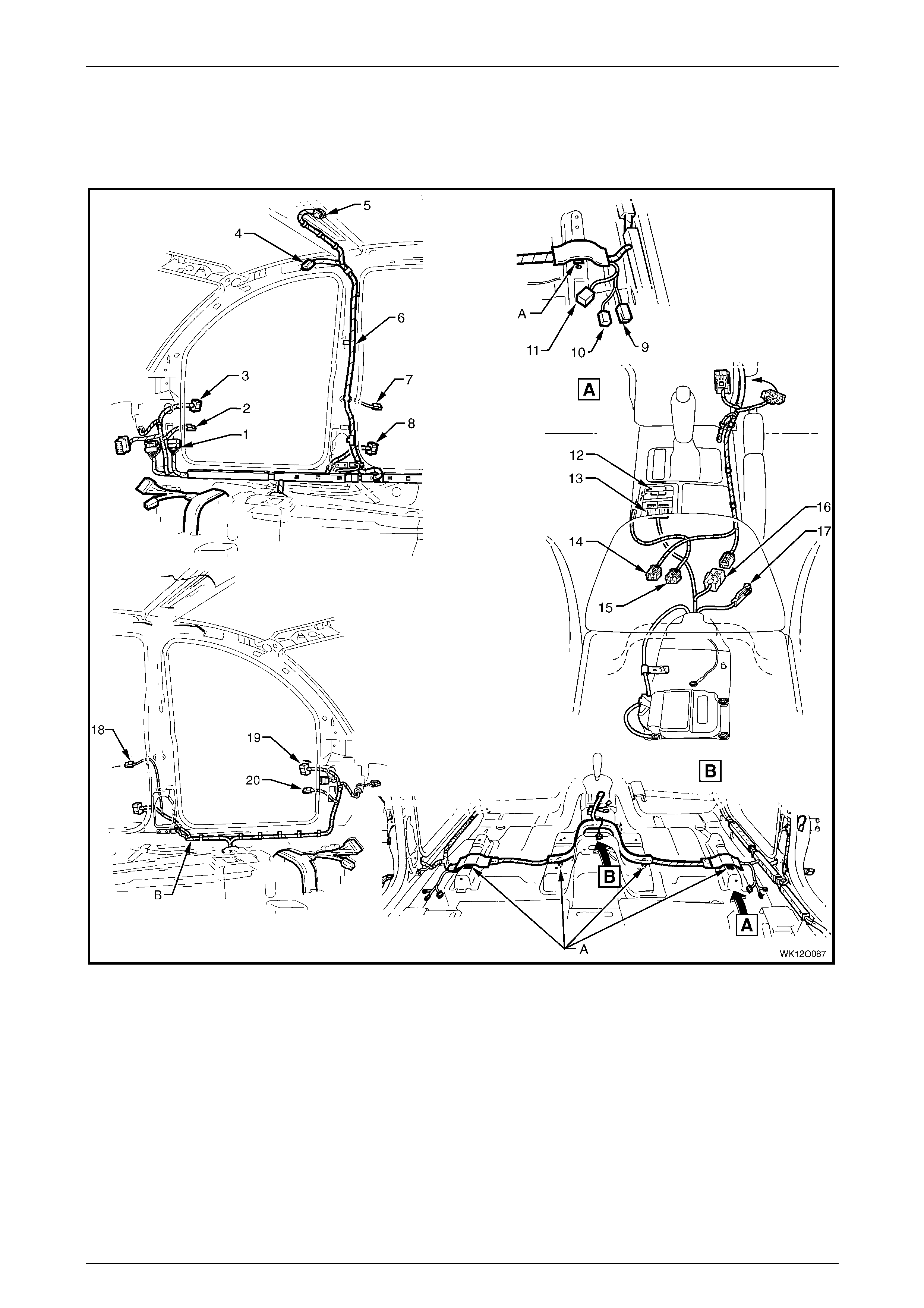
Fuses, Relays and Wi ring Harnesse s Page 12O–143
Page 12O–143
4.22 Body and Roof Wiring Harnesses – 2
Interior
Figure 12O – 116

Fuses, Relays and Wi ring Harnesse s Page 12O–144
Page 12O–144
Legend
1 Body Wiring Harness to Main Wi ring Harness Connector
(X201)
2 Door Ajar Indicator Switch Connector (S2)
3 Body Wiring Harness to Right-hand Front Door Wi ri ng
Harness Connect or (X600)
4 Roof Lamp Harness to Visor Lamp Harness
Connector (X310)
5 Dome Lamp Connector (E67) [Level 1 only]
6 Roof Lamp Harness
7 Door Ajar Indicator Switch Connector (S2)
8 Body Wiring Harness to Right-hand Rear Door Wiring
Harness Connect or (X800)
9 Seat Belt Connector (Y 128 – LH) (Y129, – RH)
10 Body Wiring Harness to Side Airbag Harness Connector
(X306 – LH) (X307 – RH)
11 Body Wiring Harness to Power Seat Harness Connector
(X302 – LH) (X308 – RH) – (X315 – D Level 5 Only)
12 Main Wiring Harness to Transmission Select or Harness
Connector (X301)
13 Side Window (Master) Switch Connector (S222)
14 Main Wiring Harness t o Consol e Wiring Harness Connector
(X309)
15 Hazard Warning S witch Connector (S120)
16 Body Wiring Harness to Main Wiring Harness Connector
(X303)
17 Park Brake Switc h Connect or (S181)
18 Door Ajar Indicator Switch Connector (S2)
19 Body Wiring Harness to Left-hand Front Door Wiring
Harness Connect or (X500)
20 Door Ajar Indicator Switch Connector (S2)
A Harness clipped to underbody as shown (4 places).
B Harness clipped to underbody, refer to
4.21 Body and Roof Wiring Harnesses – 1.
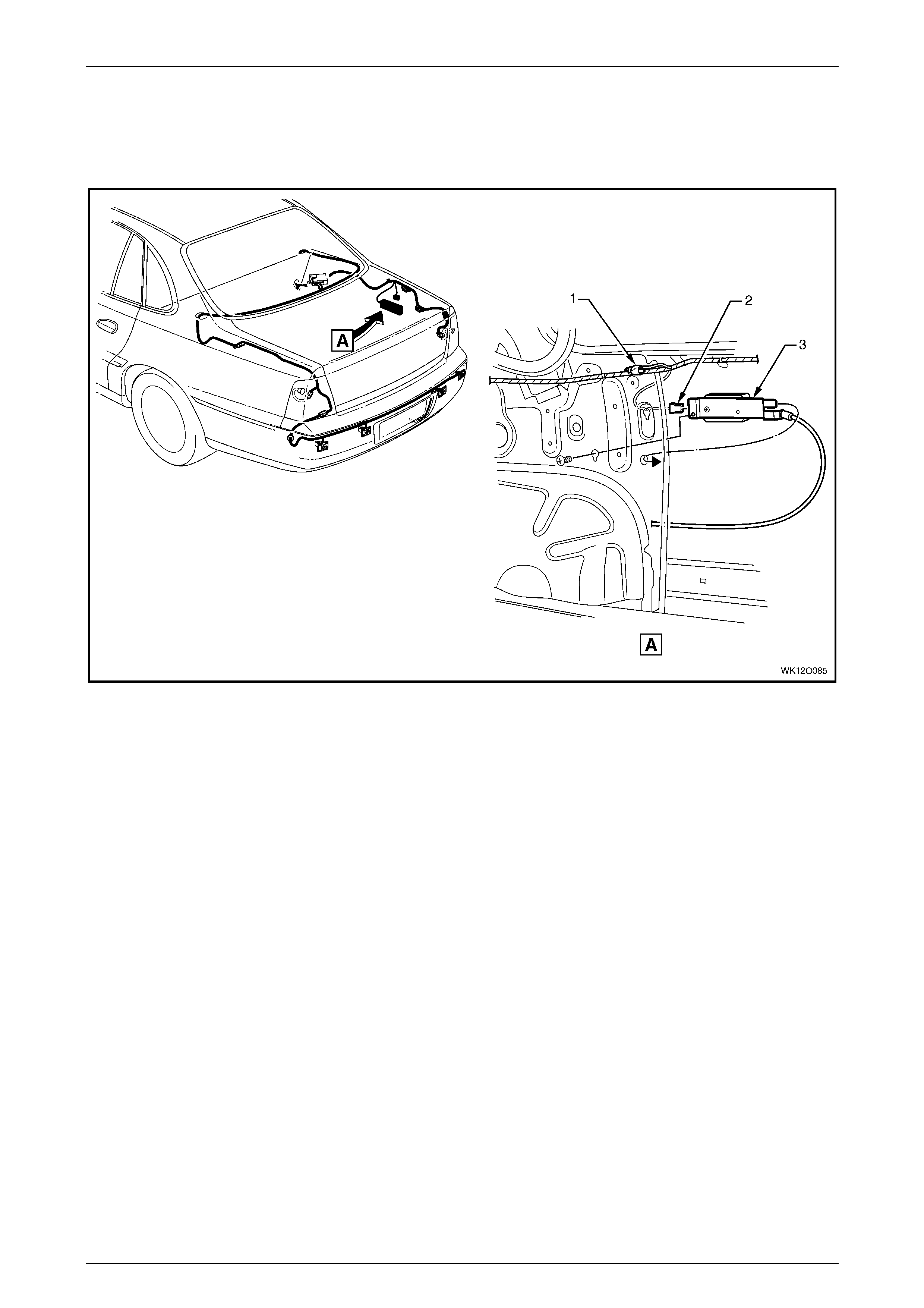
Fuses, Relays and Wi ring Harnesse s Page 12O–145
Page 12O–145
4.23 Body and Roof Wiring Harnesses – 3
Fuel Tank Filler Door Lock
Figure 12O – 117
Legend
1 Suppression Diode Fuel Tank Filler Door Lock Connector
(V7)
2 Fuel Tank Filler Door Lock Connector (Y10)
3 Fuel Tank Filler Door Lock
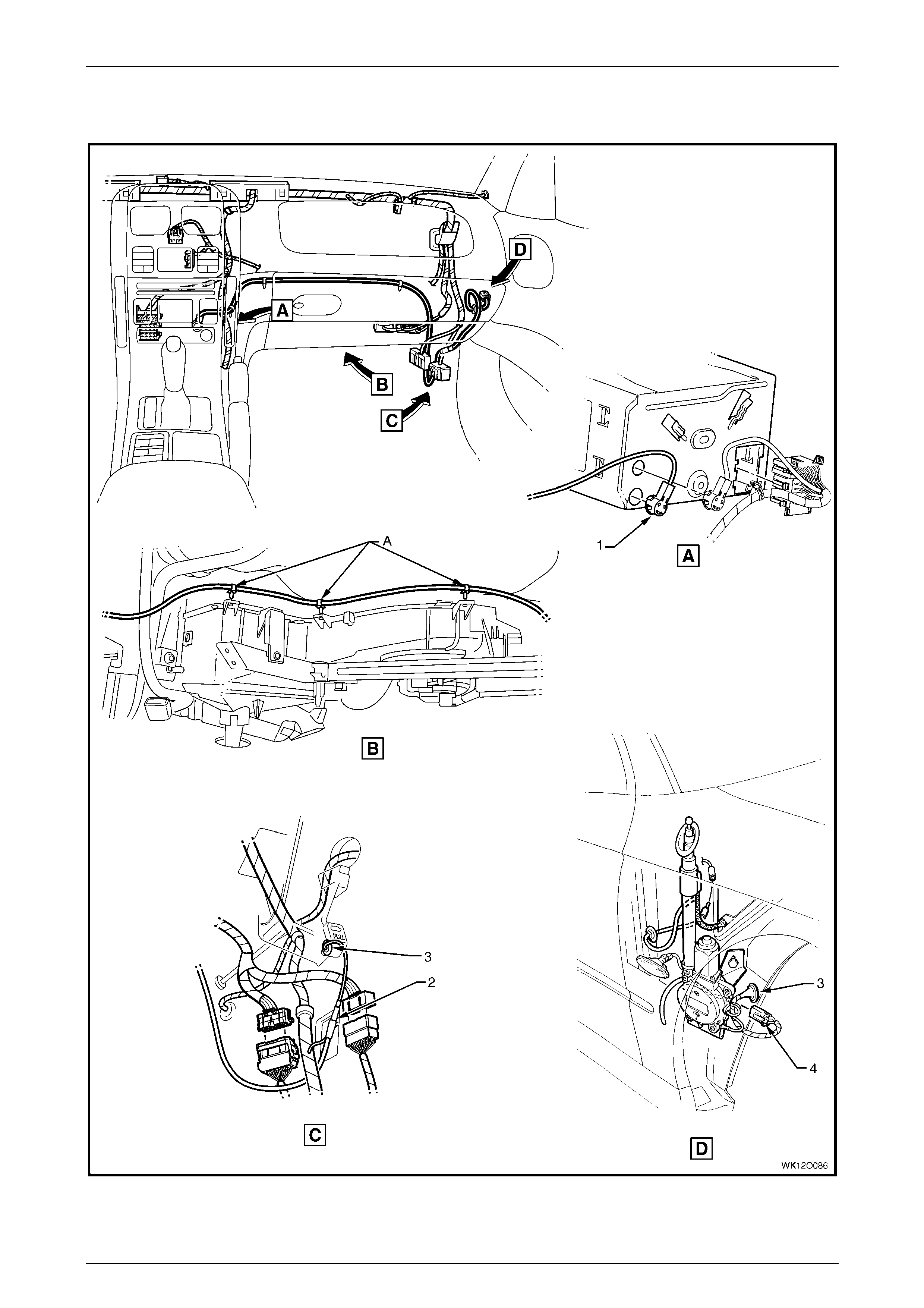
Fuses, Relays and Wi ring Harnesse s Page 12O–146
Page 12O–146
4.24 Radio Power Antenna Assembly Wiring
Figure 12O – 118

Fuses, Relays and Wi ring Harnesse s Page 12O–147
Page 12O–147
Legend
1 Power Antenna Connect or (A133 – X2)
2 Radio Power Antenna Connector (W6 – X2)
3 Antenna Lead Panel Blanking Grommet
4 Radio Power Antenna Connector (W6 – X1)
A Lead attached along integral heating, ventilation and ai r
conditi oni ng unit as shown (3 places).
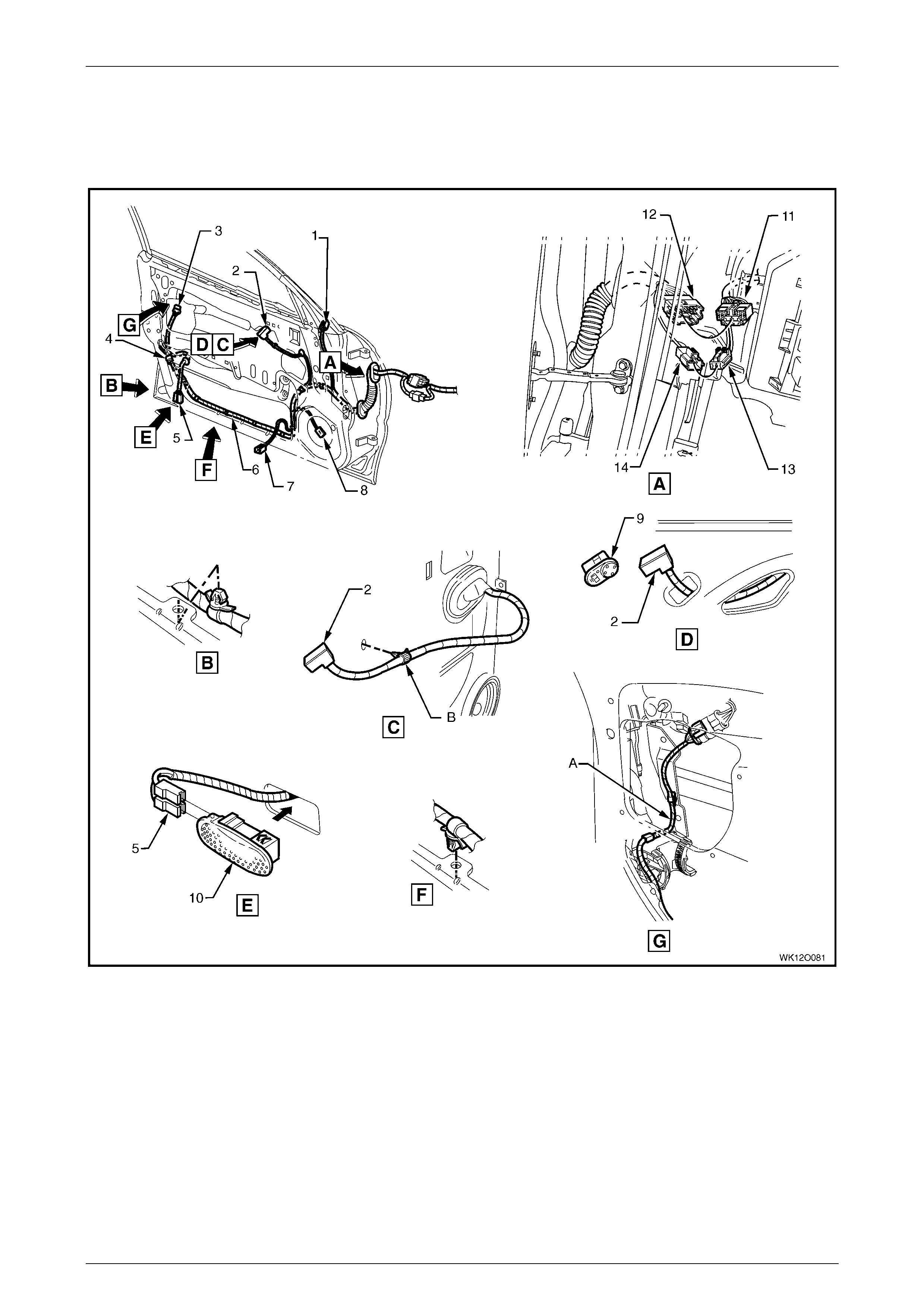
Fuses, Relays and Wi ring Harnesse s Page 12O–148
Page 12O–148
4.25 Door Wiring Harness – 1
Front Door – Level 1, 2 and 3
Figure 12O – 119

Fuses, Relays and Wi ring Harnesse s Page 12O–149
Page 12O–149
Legend
1 Outside Rear View Mirror Motor Connect or (M11)
2 Outside Rear View Mirror Rem ote Control S witc h
Connector (S 169)
3 Door Lock Switc h Connect or (S63)
4 Front Side Door Lock Actuat or Connect o r (Y 13)
5 Front Side Door Courtes y Lamp Connectors (E72)
6 Door Wiring Harness
7 Front Side Door Window Regulator Connect or (M10)
8 Radio Door Speaker Connect or (B108)
9 Outside Rear View Mirror Rem ote Control S witc h
10 Front Side Door Courtesy Lamp
11 Body Wiring Harness to Left-hand Front Door Wiring
Harness Connect or (X500)
12 Left -hand Front Door Wiring Harness t o Body Wi ri ng
Harness Connect or (X500)
13 Body Wiring Harness to Left -hand Front Door Wiring
Harness Connect or (X501)
14 Left -hand Front Door Wiring Harness t o Body Wi ri ng
Harness Connect or (X501)
A Harness rout ed as shown.
B Harness cli pped to door inner panel as shown.
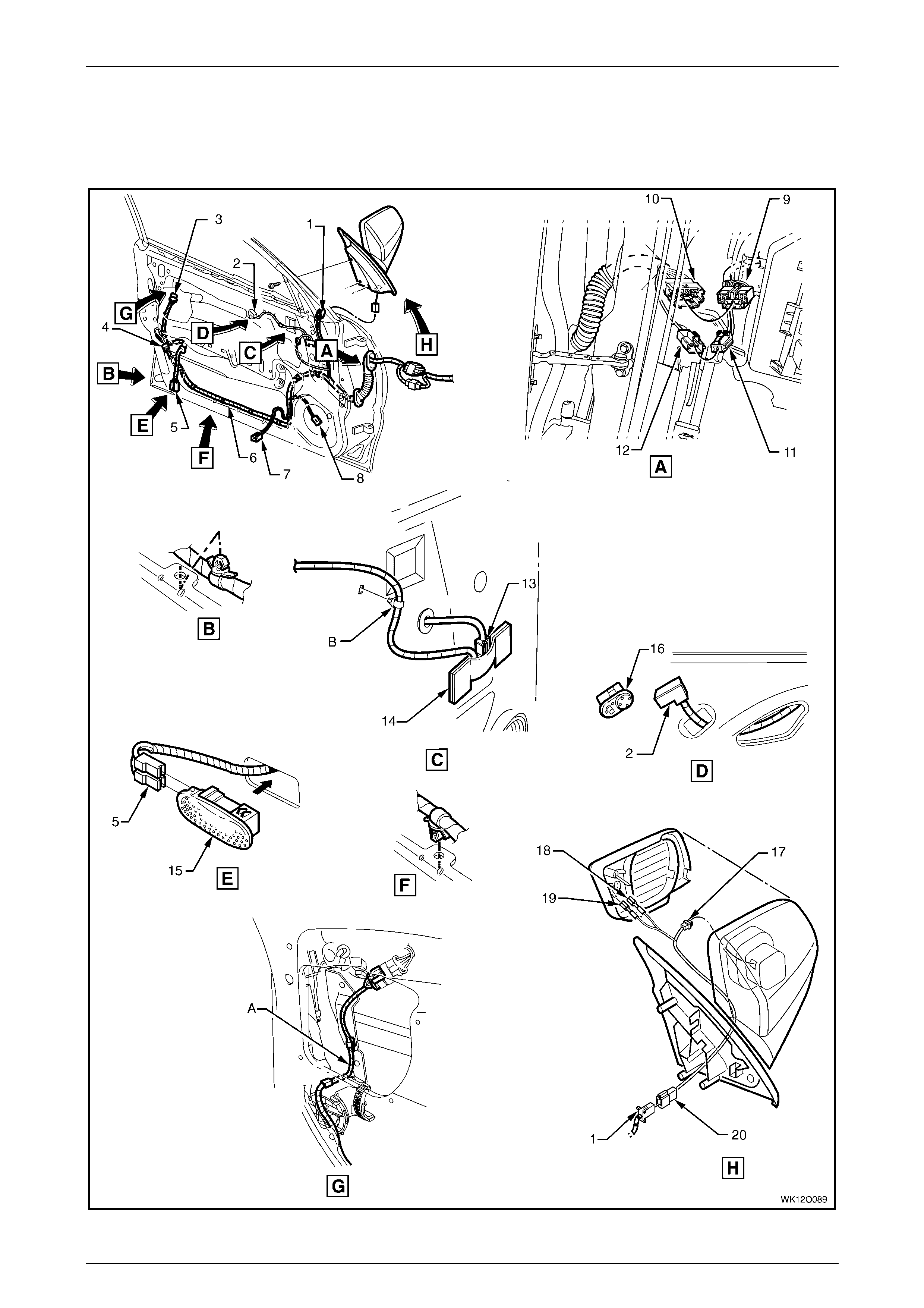
Fuses, Relays and Wi ring Harnesse s Page 12O–150
Page 12O–150
4.26 Door Wiring Harness – 2
Front Door – Level 5
Figure 12O – 120

Fuses, Relays and Wi ring Harnesse s Page 12O–151
Page 12O–151
Legend
1 Left -hand Front Door Wiring Harness t o Power Mirror
Harness Connect or (X502)
2 Outside Rear View Mirror Rem ote Control S witc h
Connector (S 169)
3 Door Lock Switc h Connect or (S63)
4 Front Side Door Lock Actuat or Connect o r (Y 13)
5 Front Side Door Courtes y Lamp Connectors (E72)
6 Door Wiring Harness
7 Front Side Door Window Regulator Connect or (M10)
8 Radio Door Speaker Connect or (B108)
9 Body Wiring Harness to Left -hand Front Door Wiring
Harness Connect or (X500)
10 Left -hand Front Door Wiring Harness t o Body Wi ri ng
Harness Connect or (X500)
11 Body Wiring Harness to Left -hand Front Door Wiring
Harness Connect or (X501)
12 Left -hand Front Door Wiring Harness t o Body Wi ri ng
Harness Connect or (X501)
13 Rear View Mirror Memory Module Connect or (A 73 – X2)
14 Rear View Mirror Memory Module
15 Front Side Door Courtesy Lamp
16 Outside Rear View Mirror Rem ote Control S witc h
17 Outside Rear View Mirror Connector (M11 – X1)
18 Outside Rear View Mirror Connector (M11 – X2)
19 Outside Rear View Mirror Connector (M11 – X3)
20 Power Mirror Harness to Left -hand Front Door Wiri ng
Harness Connect or (X502)
A Harness rout ed as shown.
B Harness cli pped to door inner panel as shown.