
HVAC Climate Control (Manual A/C) – Descri pt i on and Operati on Page 2A–1
20–MAR–2003 Page 2A–1
Section 2A
HVAC Climate Control (Manual A/C)
– Description and Operation
ATTENTION
Before performing any Service Operation or other procedure described in this Section, refer to Section 00
WARNINGS, CAUTIONS AND NOTES for correct workshop practices with regard to safety and/or property
damage.
1 General Information............................................................................................................................... 2
2 General Description............................................................................................................................... 3
2.1 HVAC Inlet, Ducting And Outlets..........................................................................................................................4
3 Manual HVAC Controller....................................................................................................................... 6
4 Specifications......................................................................................................................................... 7
Techline

HVAC Climate Control (Manual A/C) – Descri pt i on and Operati on Page 2A–2
20–MAR–2003 Page 2A–2
1 General Information
Two levels of air conditioning are fitted to the MY2004 WK Series vehicles and are described as follows:
HVAC Climate Control (Manual A/C): This system uses a ‘rotary dial’ type controller to select the desired operating
modes and temperature. It will be generally referred to as ‘manual’ air conditioning in this Section as well as these
following Sections:
• Section 2B HVAC CLIMATE CONTROL (MANUAL A/C) – REMOVAL AND INSTALLATION
• Section 2C HVAC CLIMATE CONTROL (MANUAL A/C) – SERVICING AND DIAGNOSIS
HVAC Occupant Climate Control (Auto A/C): This system uses an electronic ‘push button’ type controller to select the
desired operating modes and temperature. It will be generally referred to as ‘auto’ air conditioning or Occupant Climate
Control (OCC). This system may be of single zone or dual zone configuration.
For information relating specifically to the HVAC Occupant Climate Control (Auto A/C) system refer to:
• Section 2D HVAC OCCUPANT CLIMATE CONTROL (AUTO A/C) – DESCRIPTION AND OPERATION
• Section 2E HVAC OCCUPANT CLIMATE CONTROL (AUTO A/C) – REMOVAL AND INSTALLATION
• Section 2F HVAC OCCUPANT CLIMATE CONTROL (AUTO A/C) – DIAGNOSTICS
For information relating to the HVAC Occupant Climate Control (Auto A/C) system not covered in Section 2D, 2E and
2F, refer to this Section as well as these following Sections:
• Section 2B HVAC CLIMATE CONTROL (MANUAL A/C) – REMOVAL AND INSTALLATION
• Section 2C HVAC CLIMATE CONTROL (MANUAL A/C) – SERVICING AND DIAGNOSIS
HVAC Climate Control (Manual A/C) – Descri pt i on and Operati on Page 2A–3
20–MAR–2003 Page 2A–3
2 General Description
An integrated air conditioning system is fitted to all MY2004 WK Series models. This integrated system combines both
the heating and cooling functions in a single unit. The vehicle’s interior can be heated, cooled or vented (or a
combination of these operations) depending on the modes and switches activated on the HVAC controller. The controller
is mounted below centre ventilation outlets, behind the centre instrument panel centre trim assembly.
Level 1 WK Series models are produced for LHD markets only and are fitted with an instrument panel and manual air
conditioning system that is carried over from low series VY models including the manual HVAC controller. Level 2 to 5
WK Series models are fitted with an automatic air conditioning system, Occupant Climate Control (Auto A/C), similar to
high level VY Series models. These model levels are fitted with an instrument panel and OCC control module that is
unique to the WK Series. A rear remote controller, allowing rear passengers to alter temperature and fan speeds, is fitted
to Level 5 vehicles. Excluding the rear remote controller, the operation of the air conditioning system (including the
symbols used to indicate the various ventilation modes) is the same as that for VY Series models. For further descriptive
information on the OCC (Auto A/C) system fitted to Level 2 to 5 vehicles, refer to Section 2D HVAC OCCUPANT
CLIMATE CONTROL (AUTO A/C) – DESCRIPTION AND OPERATION.
Apart from a minor change to the front of the HVAC case to accommodate the unique instrument panel on Level 2 to 5
WK Series models, both LHD and RHD HVAC units, as well as all under hood air conditioning components, are carried
over from the VY Series.
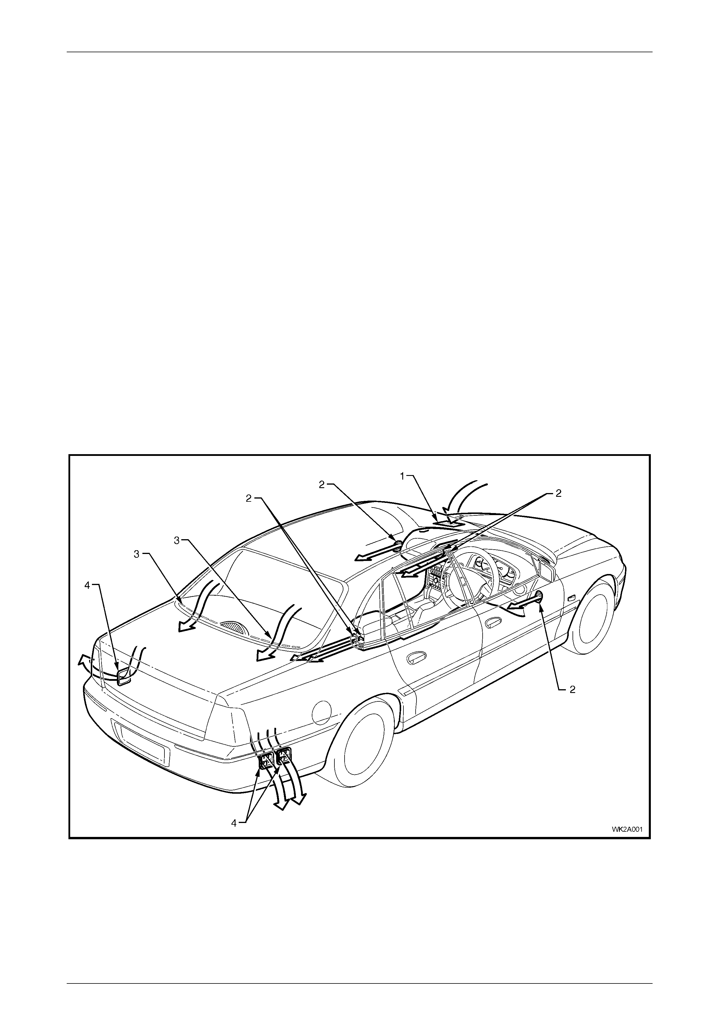
Air enters the heating, ventilation and air conditioning system (HVAC) from under the plenum chamber cover. The air
then passes through the blower motor/fan, evaporator and heater assemblies, to be cooled or heated as required. Air
leaves the HVAC unit and enters the vehicle interior through the centre, side, floor or demist outlets. The cabin outlets
through which the air is emitted is dependent upon the mode selected via the mode control.
Cabin air moves through to the rear compartment via two sets of five ventilation apertures located at the rear of the
parcel shelf. When the cabin is sealed, i.e. all movable windows are fully up, air exits the vehicle through three body
mounted air outlets located at the rear of the vehicle behind the rear bumper bar fascia.
Figure 2A – 1
Legend
1 HVAC Plenum Inlet 3 Parcel Shelf Ventilation Apertures
2 HVAC Cabin Air Outlet 4 HVAC Body Air Outlet
HVAC Climate Control (Manual A/C) – Descri pt i on and Operati on Page 2A–4
20–MAR–2003 Page 2A–4
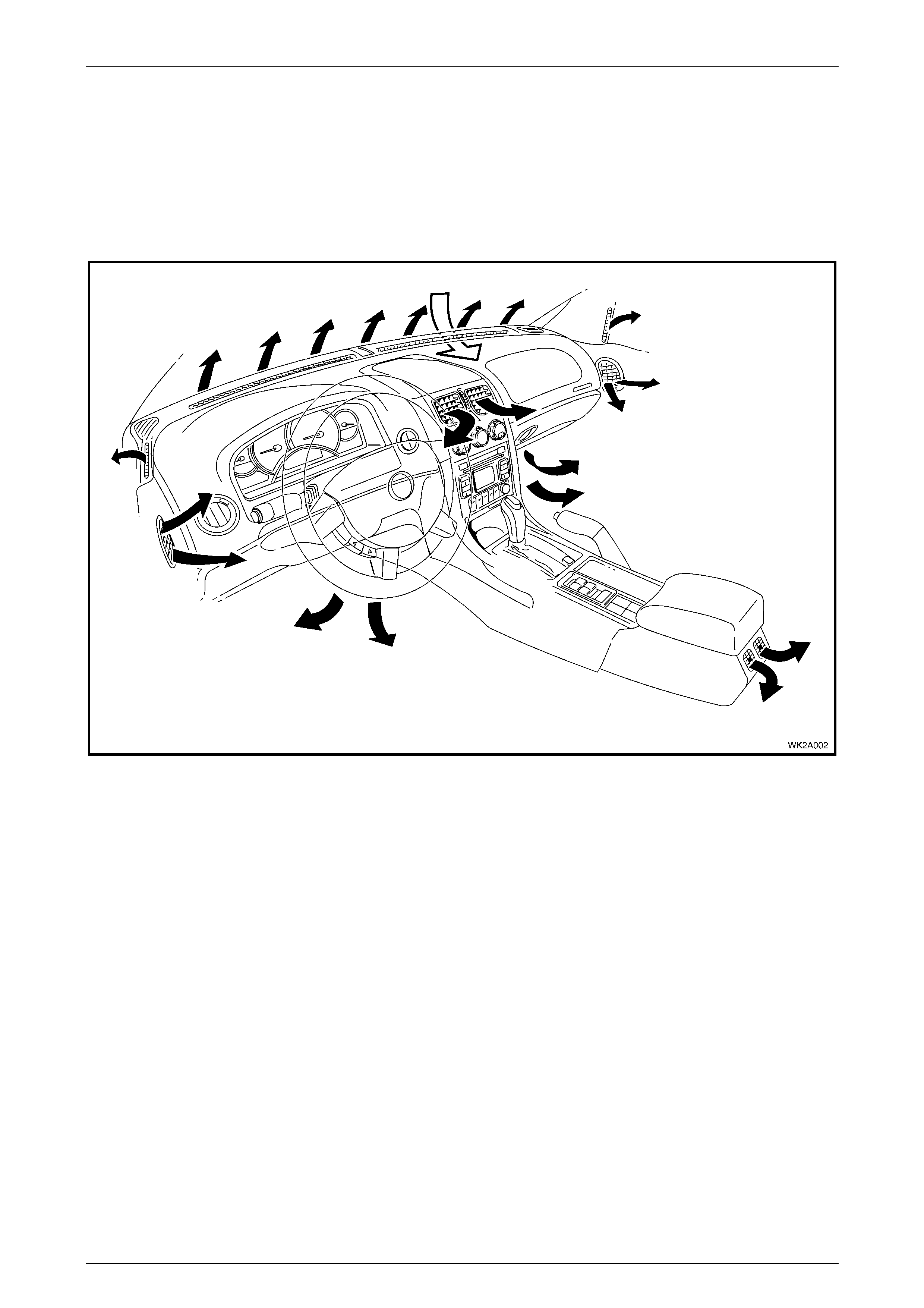
2.1 HVAC Inlet, Ducting And Outlets
The HVAC system inlet and ducting are identical to VY Series models. For Level 2 to 5 WK Series models, minor design
and appearance variations apply to the instrument panel centre ventilation outlet.
For more comprehensive information relating to the HVAC system inlet, ducting and outlets, refer to Section 2A,
2.1 HVAC INLET, DUCTS AND OUTLETS in the MY2003 VY and V2 Series Service Information.
Figure 2A – 2 shows the HVAC system cabin outlets as applicable to Level 1 (Manual A/C) WK Series models.
Figure 2A – 2
HVAC Climate Control (Manual A/C) – Descri pt i on and Operati on Page 2A–5
20–MAR–2003 Page 2A–5
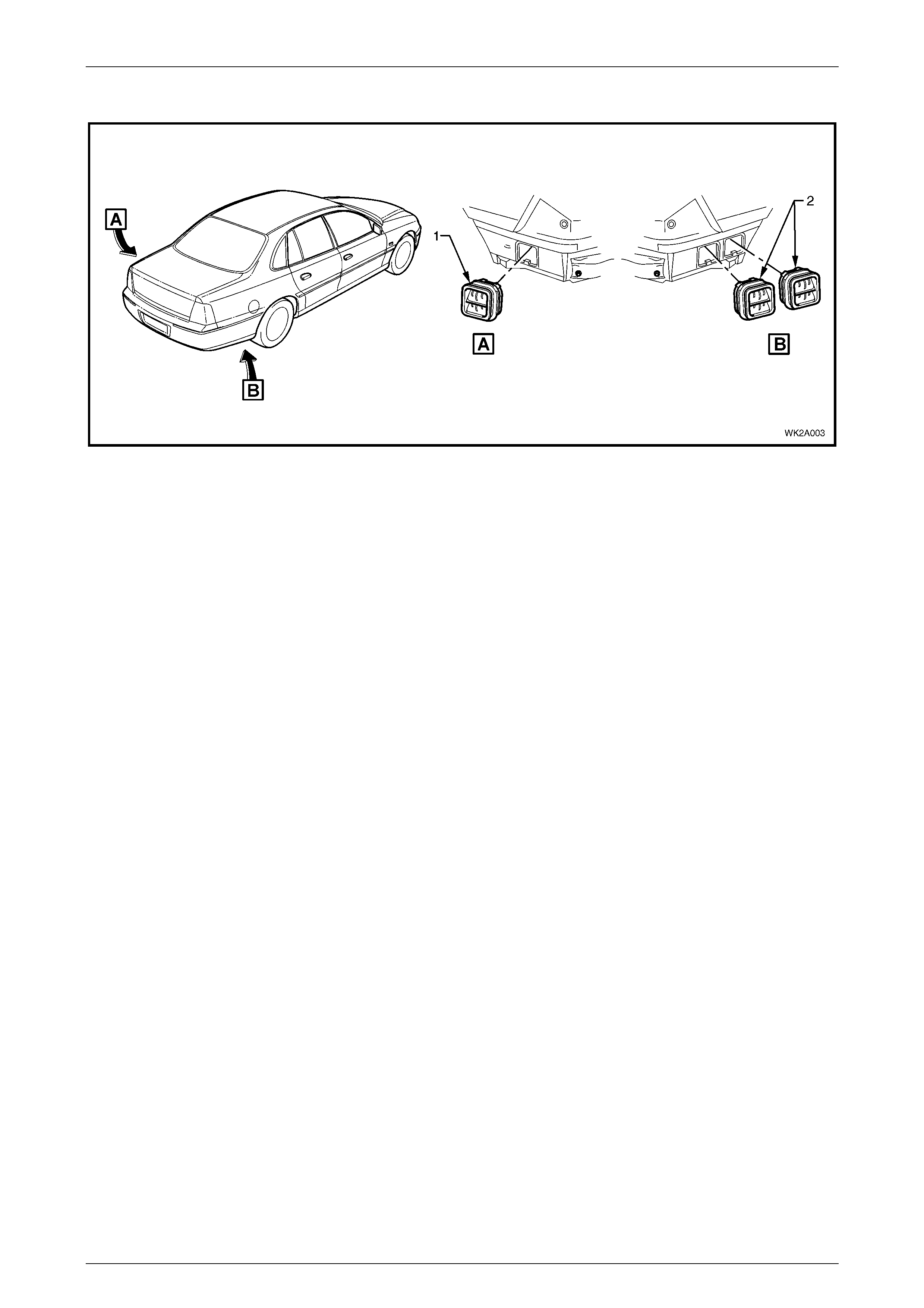
Figure 2A – 3 shows the locations of body ventilation outlets as installed to all WK Series models.
Figure 2A – 3
Legend
1 Body Ventilation Outlets – LHS 2 Body Ventilation Outlet – RHS
HVAC Climate Control (Manual A/C) – Descri pt i on and Operati on Page 2A–6
20–MAR–2003 Page 2A–6
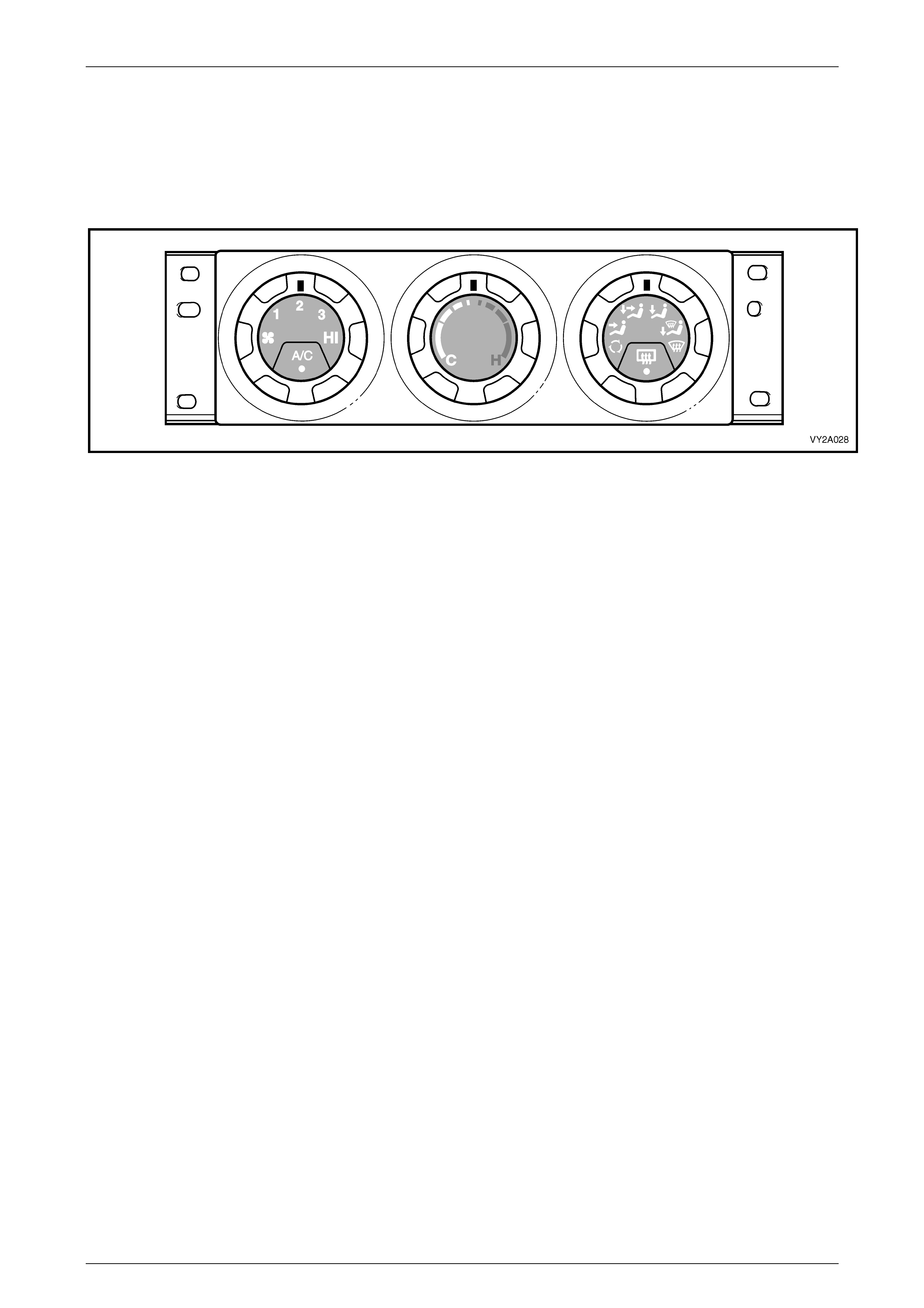
3 Manual HVAC Controller
Figure 2A – 4 shows the manual type HVAC controller as fitted to all Level 1 MY2004 WK Series models. The
construction, function and installation of this controller is the same as that fitted MY2003 VY Series models with manual
A/C systems. For further information relating to the manual HVAC controller, refer to Section 2A, 2.2 MANUAL HVAC
CONTROLLER in the MY2003 VY and V2 Series Service Information.
Figure 2A – 4

HVAC Climate Control (Manual A/C) – Descri pt i on and Operati on Page 2A–7
20–MAR–2003 Page 2A–7
4 Specifications
For all specifications relating to the HVAC Climate Control (Manual A/C) as fitted to Level 1 MY2004 WK Series models,
refer to Section 2A, 3 SPECIFICATIONS in the MY2003 VY and V2 Series service information, noting that the
specifications relating specifically to RHD models do not apply.