
HVAC Climat e Control (Manual A/C) – Servi cing and Diagnosis Page 2C–1
20–MAR–2003 Page 2C–1
Section 2C
HVAC Climate Control (Manual A/C) –
Servicing and Diagnosis
ATTENTION
Before performing any Service Operation or other procedure described in this Section, refer to Section 00
WARNINGS, CAUTIONS AND NOTES for correct workshop practices with regard to safety and/or property
damage.
1 General Information............................................................................................................................... 2
2 Wiring Diagrams .................................................................................................................................... 3
Connectors: HVAC Climate Control (Manual A/C) System.................................................................................4
Connectors: HVAC Climate Control (Manual A/C) System Continued ..............................................................5
Connectors: HVAC Climate Control (Manual A/C) System Continued ..............................................................6
Wiring Diagram: HVAC Climate Control (Manual A/C) System – V6 (LHD) .......................................................7
Wiring Diagram: HVAC Climate Control (Manual A/C) System – GEN III V8 (LHD)...........................................8
Techline
Techline
Techline

HVAC Climat e Control (Manual A/C) – Servi cing and Diagnosis Page 2C–2
20–MAR–2003 Page 2C–2
1 General Information
The servicing and diagnosis information of the HVAC system for MY2004 WK Series models carries over from the
information provided in Section 2C, HVAC Climate Control (Manual A/C) – Servicing and Diagnosis in the MY2003 VY
and V2 Series Service Information, noting the following:
• The information contained in 7.ELECTRICAL COMPONENT TESTS applies only to Level 1 WK Series models.
• The information contained in 8.VACUUM RETENTION TESTS applies as follows:
Vacuum Circuit Schematic (Figure 2C – 19) – Level 1 WK Series models only.
Vacuum Loss Default Settings information and schematic (Figure 2C – 21) – Level 1 WK Series models only.
8.1 HVAC System Check Valve – all WK Series models.
8.2 Vacuum Tank – all WK Series models.
8.3 Vacuum Mode Valve – Level 1 WK Series models only.
8.4 Water Valve Vacuum Switch – Level 1 WK Series models only.
8.5 Vacuum Actuators and Lines – Level 1 WK Series models only.
8.6 Vacuum Actuators – all WK Series models.
8.7 Water Valve – all WK Series models.
The information contained in 2 WIRING DIAGRAMS in this Section applies only to Level 1 LHD MY2004 WK Series
models. Level 1 MY2004 WK Series models are not built for RHD markets.
For additional diagnostic information on Level 2 to 5 WK Series models, i.e. WK models equipped with HVAC Occupant
Climate Control (Auto A/C), which is not contained within the above referrals, refer to following Sections as required:
• Section 2F HVAC OCCUPANT CLIMATE CONTROL (AUTO A/C) – DIAGNOSTICS in the MY2003 VY and V2
Series Service Information, for diagnostic information common to VY Series models,
• Section 2F HVAC OCCUPANT CLIMATE CONTROL (AUTO A/C) – DIAGNOSTICS, for diagnostic information
unique to MY2004 WK Series models.
HVAC Climat e Control (Manual A/C) – Servi cing and Diagnosis Page 2C–3
20–MAR–2003 Page 2C–3
2 Wiring Diagrams
The following figures provide electrical connector diagrams and wiring diagrams applicable to HVAC Climate Control
(Manual A/C) systems as fitted to Level 1 LHD MY2004 WK Series vehicles. These diagrams should be used as an aid
to diagnosing circuit faults. The content of these figures is as follows:
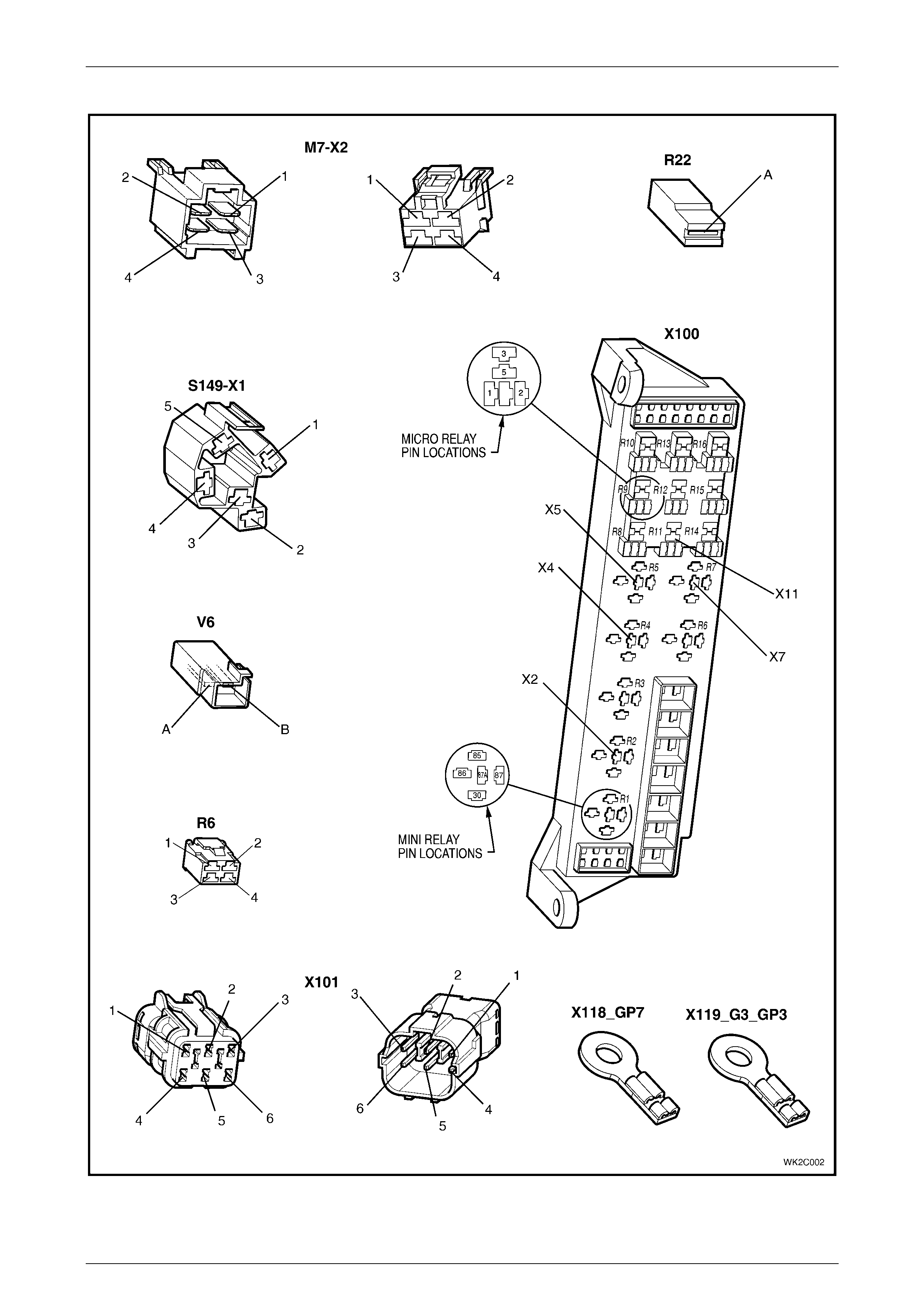
• Electrical connectors (A15 – M7) – refer to Figure 2C – 1
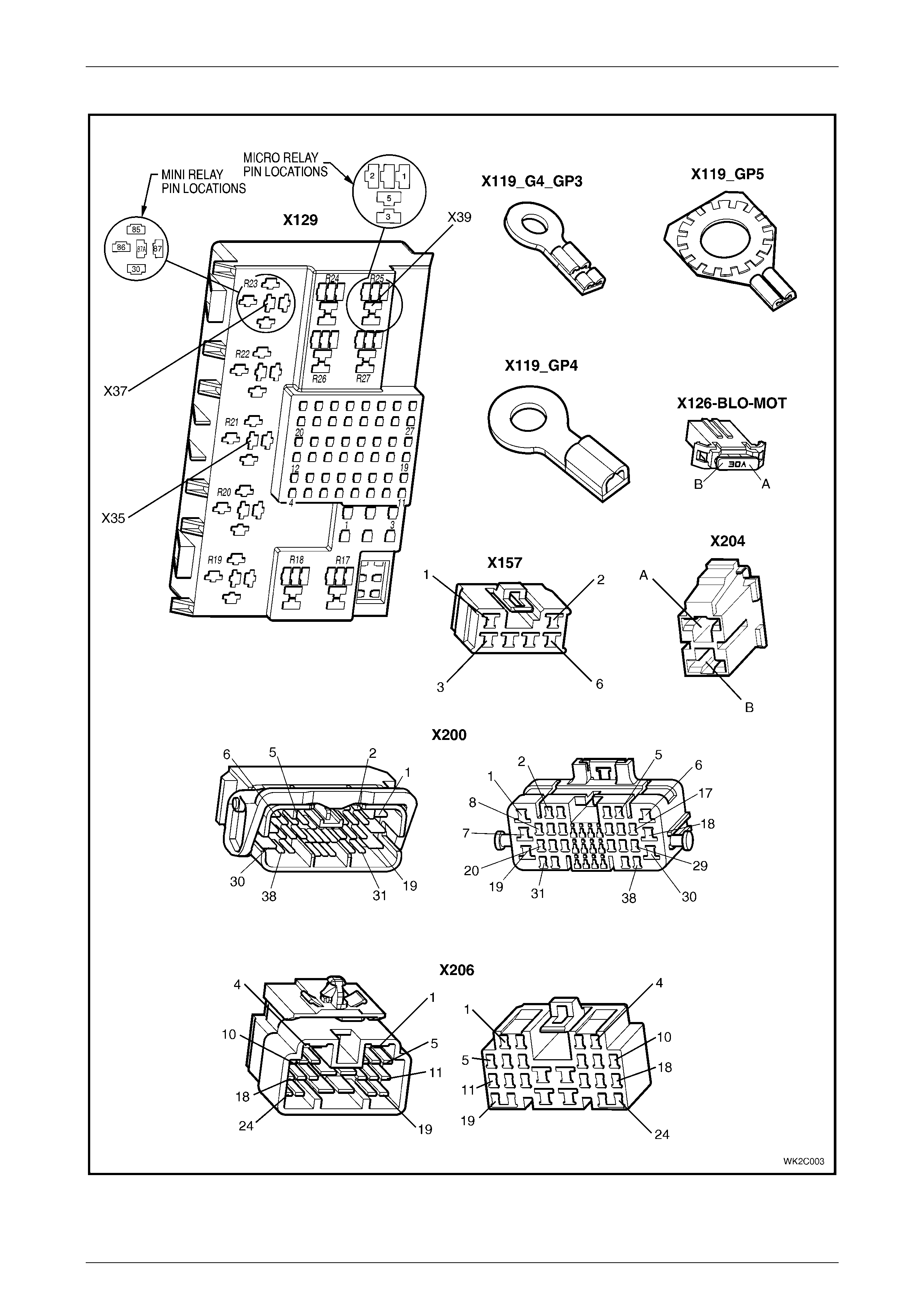
• Electrical connectors continued (M7– X119) – refer to Figure 2C – 2
• Electrical connectors continued (X119 – X206) – refer to Figure 2C – 3
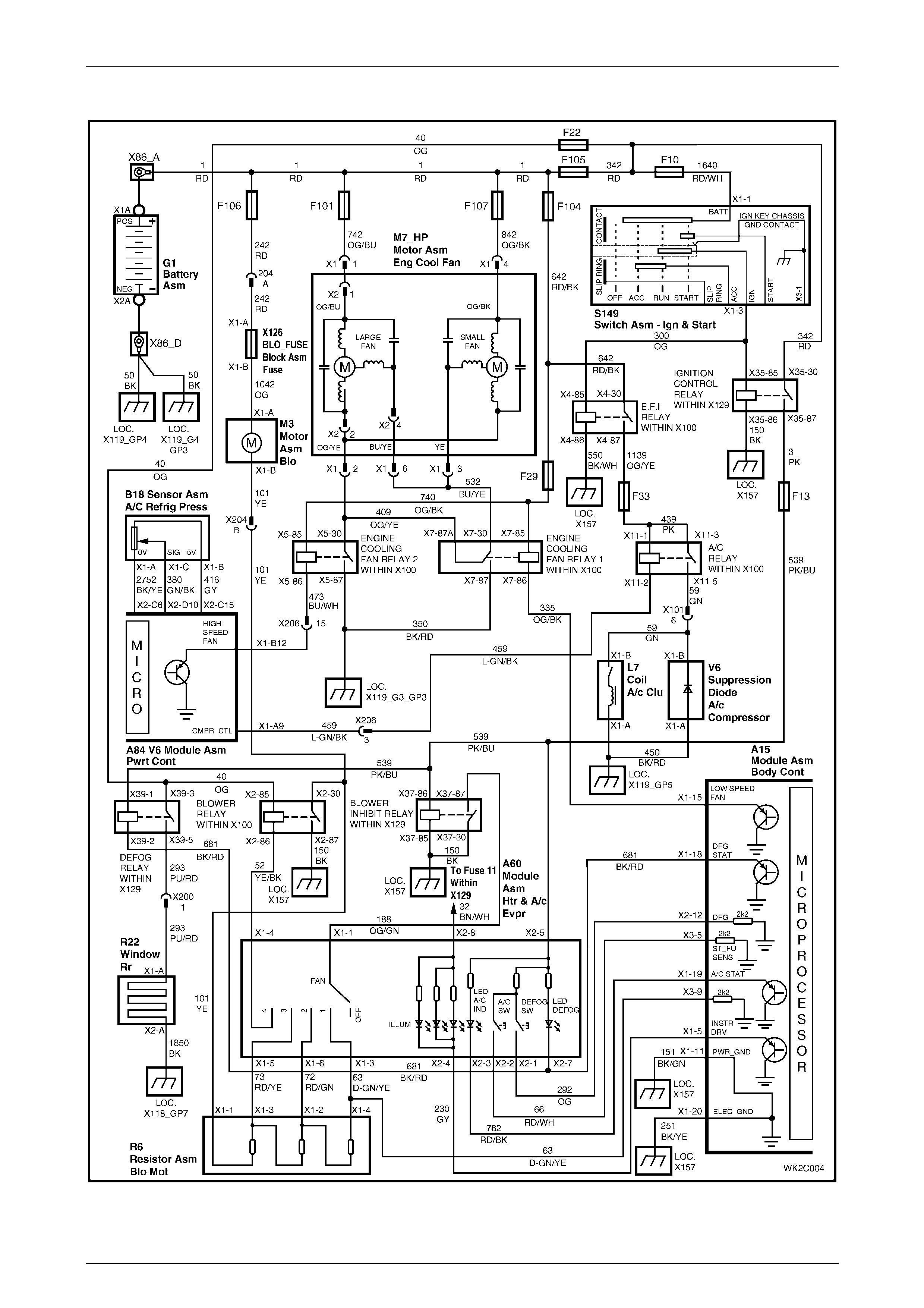
• Wiring diagram: HVAC Climate Control (Manual A/C) system, V6 (LHD) – refer to Figure 2C – 4
• Wiring diagram: HVAC Climate Control (Manual A/C) system, GEN III V8 (LHD) – refer to Figure 2C – 5
For wiring diagrams related to the Occupant Climate Control (Auto A/C) system as fitted to Level 2 to 5 MY2004
WK Series vehicles, refer to Section 2F, 4 WIRING DIAGRAMS.
In the following wiring diagrams (Figure 2C – 4 and Figure 2C – 5) all components are described and displayed in
accordance to the Integrated Vehicle Electrical Design (IVED) standard as applied to MY2004 WK Series vehicles. To
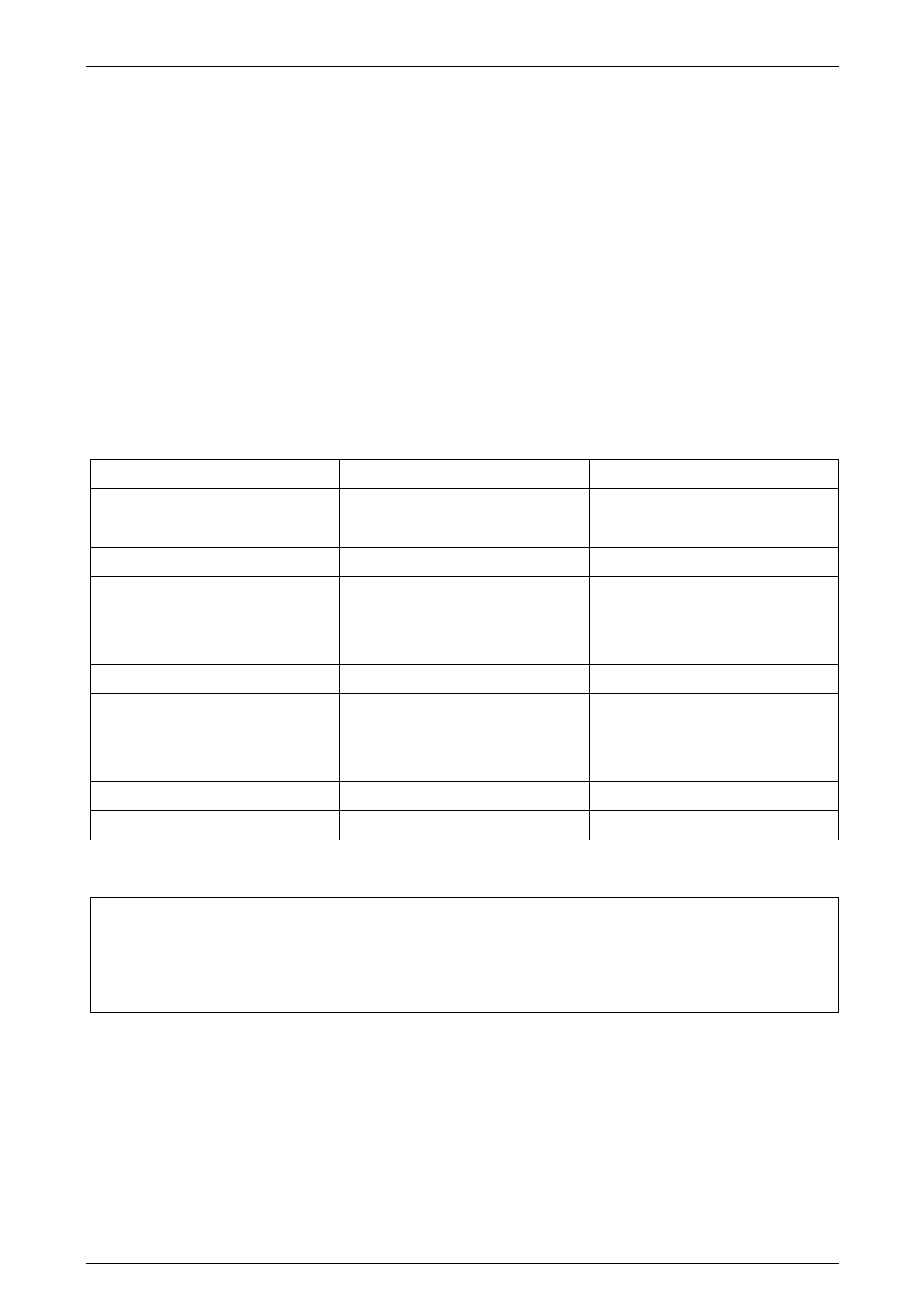
assist in wiring diagram interpretation, refer to the following table:
IVED Description IVED Component Identification Common Description
Switch Asm – Ign & Start S149 Ignition Switch
V6 Module Asm Pwrt Cont A84 V6 Powertrain Control Module
V8 Module Asm Pwrt Cont A84 GEN III V8 Powertrain Control Module
Module Asm Body Cont A15 Body Control Module
Motor Asm Blo M3 Blower Motor
Resistor Asm Blo Mot R6 Blower Motor Resistor
Module Asm Htr & A/c Evpr A60 Manual HVAC Controller
Coil A/c Clu L7 Compressor Clu tch
Sensor Asm A/C Refrig Press B18 A/C Pressure Transducer
Motor Asm Eng Cool Fan M7_HP V6 High Power Cooling Fan System
Motor Asm Eng Cool Fan M7_V8 GEN III V8 Cooling Fan System
Window Rear R22 Heated Rear Window
The following table lists the IVED standard wire colour abbreviations:
BK Black D-GN Dark green L-GN Light green RD Red
BU Blue GN Green OG Orange TN Tan
BN Brown GY Grey PK Pink WH White
D-BU Dark blue L-BU Light blue PU Purple YE Yellow
NOTE
For electrical connector locations and additional
wiring diagram information refer to Section 12P
WIRING DIAGRAMS.

HVAC Climat e Control (Manual A/C) – Servi cing and Diagnosis Page 2C–4
20–MAR–2003 Page 2C–4
Connectors: HVAC Climate Control (Manual A/C) S ystem
Figure 2C – 1
HVAC Climat e Control (Manual A/C) – Servi cing and Diagnosis Page 2C–5
20–MAR–2003 Page 2C–5
Connectors: HVAC Climate Control (Manual A/C) System Continued
Figure 2C – 2
HVAC Climat e Control (Manual A/C) – Servi cing and Diagnosis Page 2C–6
20–MAR–2003 Page 2C–6
Connectors: HVAC Climate Control (Manual A/C) System Continued
Figure 2C – 3
HVAC Climat e Control (Manual A/C) – Servi cing and Diagnosis Page 2C–7
20–MAR–2003 Page 2C–7
Wiring Diagram: HVAC Climate Control (Manual A/C) System – V6 (LHD)
Figure 2C – 4
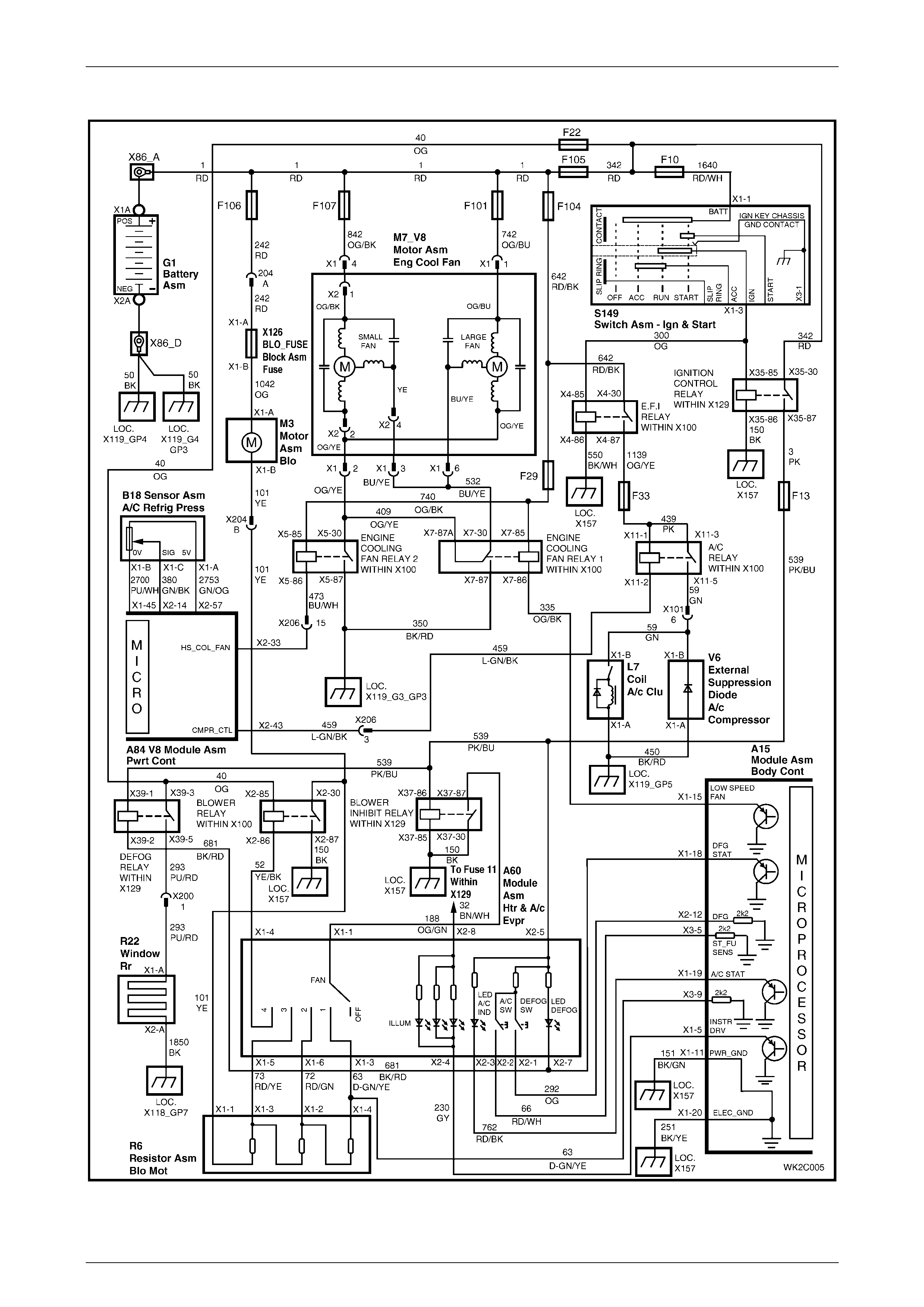
HVAC Climat e Control (Manual A/C) – Servi cing and Diagnosis Page 2C–8
20–MAR–2003 Page 2C–8
Wiring Diagram: HVAC Climate Control (Manual A/C) System – GEN III V8 (LHD)
Figure 2C – 5