
HVAC Occupant Climate Control (Auto A/C) – Description and Operation Page 2D–1
20–MAR–2003 Page 2D–1
Section 2D
HVAC Occupant Climate Control (Auto A/C) –
Description and Operati on
ATTENTION
Before performing any Service Operation or other procedure described in this Section, refer to Section 00
WARNINGS, CAUTIONS AND NOTES for correct workshop practices with regard to safety and/or property
damage.
1 General Information............................................................................................................................... 2
2 General Description............................................................................................................................... 3
3 Description ............................................................................................................................................. 4
3.1 HVAC Inlet, Ducting And Outlets..........................................................................................................................4
3.2 OCC Control Module..............................................................................................................................................5
OCC Control Module configurations....................................................................................................................6
Left-hand drive....................................................................................................................................................6
Right-hand drive.................................................................................................................................................7
OCC Control Module components........................................................................................................................8
OCC Control Module electrical connection..........................................................................................................9
Connector X1 – LHD and RHD.........................................................................................................................10
Connector X2 – LHD.........................................................................................................................................11
Connector X2 – RHD........................................................................................................................................12
3.3 Multi Function Display.........................................................................................................................................13
Multi Function Display graphics.........................................................................................................................14
3.4 Rear Remote Control ...........................................................................................................................................15
Rear Remote Control components.....................................................................................................................17
Rear Remote Control electrical connection.......................................................................................................18
Connector X1 – LHD and RHD.........................................................................................................................18
4 Operation.............................................................................................................................................. 19
5 Specifications....................................................................................................................................... 20
Techline
Techline
Techline

HVAC Occupant Climate Control (Auto A/C) – Description and Operation Page 2D–2
20–MAR–2003 Page 2D–2
1 General Information
HVAC Occupant Climate Control (Auto A/C) is fitted as standard equipment Level 2 to 5 WK Series vehicles. It will be
generally referred to as ‘Occupant Climate Control (OCC)’ or ‘OCC (Auto A/C)’ air conditioning in this Section and the
following Sections:
• Section 2E HVAC OCCUPANT CLIMATE CONTROL (AUTO A/C) – REMOVAL AND INSTALLATION
• Section 2F HVAC OCCUPANT CLIMATE CONTROL (AUTO A/C) – DIAGNOSTICS
Information in this Section, Section 2E and Section 2F is relevant to HVAC Occupant Climate Control (Auto A/C) only.
For information relating to the HVAC Occupant Climate Control (Auto A/C) system not covered in this Section,
Section 2E or Section 2F, refer to the following Sections:
• Section 2A HVAC CLIMATE CONTROL (MANUAL A/C) – DESCRIPTION AND OPERATION
• Section 2B HVAC CLIMATE CONTROL (MANUAL A/C) – REMOVAL AND INSTALLATION
• Section 2C HVAC CLIMATE CONTROL (MANUAL A/C) – SERVICING AND DIAGNOSIS

HVAC Occupant Climate Control (Auto A/C) – Description and Operation Page 2D–3
20–MAR–2003 Page 2D–3
2 General Description
The HVAC Occupant Climate Control system as fitted to MY2004 WK Series uses the same basic components as the
manual air conditioning fitted to MY2003 VY Series models and MY2004 WK Series Level 1 models. Major components
such as the condenser, filter drier receiver, compressor, evaporator, heater core, blower fan, cooling fans and water
valve are common to both manual and OCC (Auto A/C) air conditioning systems.
Sensors and components, which are fitted to the OCC (Auto A/C) system and not the manual air conditioning system,
include the following:
• Occupant climate control module – unique to WK Series models
• Multi-function display module – unique to W K Series models
• Rear remote control (Level 5 only) – unique to W K Series models
• In-car temperature sensor – common to VY and WK Series models
• Sun load sensor – common to VY and WK Series models
• Ambient temperature sensor – common to VY and WK Series models
• Evaporative temperature sensor – common to VY and WK Series models
• Vacuum solenoid pack – common to VY and WK Series models
• Water valve vacuum switch valve (LHD models only) – common to VY and WK Series models
• Air mix door motor/s – common to VY and WK Series models
NOTE
Sun load sensing is an additional function of the
ambient light sensor / remote receiver.
Accordingly this sensor is still fitted to vehicles
with manual type air conditioning.
Where an OCC (Auto A/C) system is fitted to MY2004 WK Series vehicles, it may be either single zone or dual zone. All
LHD models are equipped with single zone systems. All RHD models are equipped with dual zone systems.
Single zone OCC control modules are fitted with one temperature control button, refer to Figure 2D – 3. Dual zone OCC
control modu le s are fitted with two temperature control butto ns, refer to Figure 2D – 4.This allows both the driver and the
front seat passenger to individually select their desired comfort level of temperature setting. When dual zone mode is
operating, the temperature of the air flowing from the passenger’s floor, face and side vents will be different to that of the
driver’s floor, face and side vents. For information on the operation of single zone and dual zone OCC control modules
refer to 4 OPERATION, in this Section.
Level 5 MY2004 WK Series vehicles are fitted with a rear remote control, which allows rear passengers to control the
temperature, fan speed and some operational modes of the HVAC system. The rear remote control is combined with
certain audio controls and is located in the centre of the headlining, forward of the rear passenger seating area.
Refer to 3.4 Rear Remote Control in this Section for further information on the rear remote control.
HVAC Occupant Climate Control (Auto A/C) – Description and Operation Page 2D–4
20–MAR–2003 Page 2D–4
3 Description
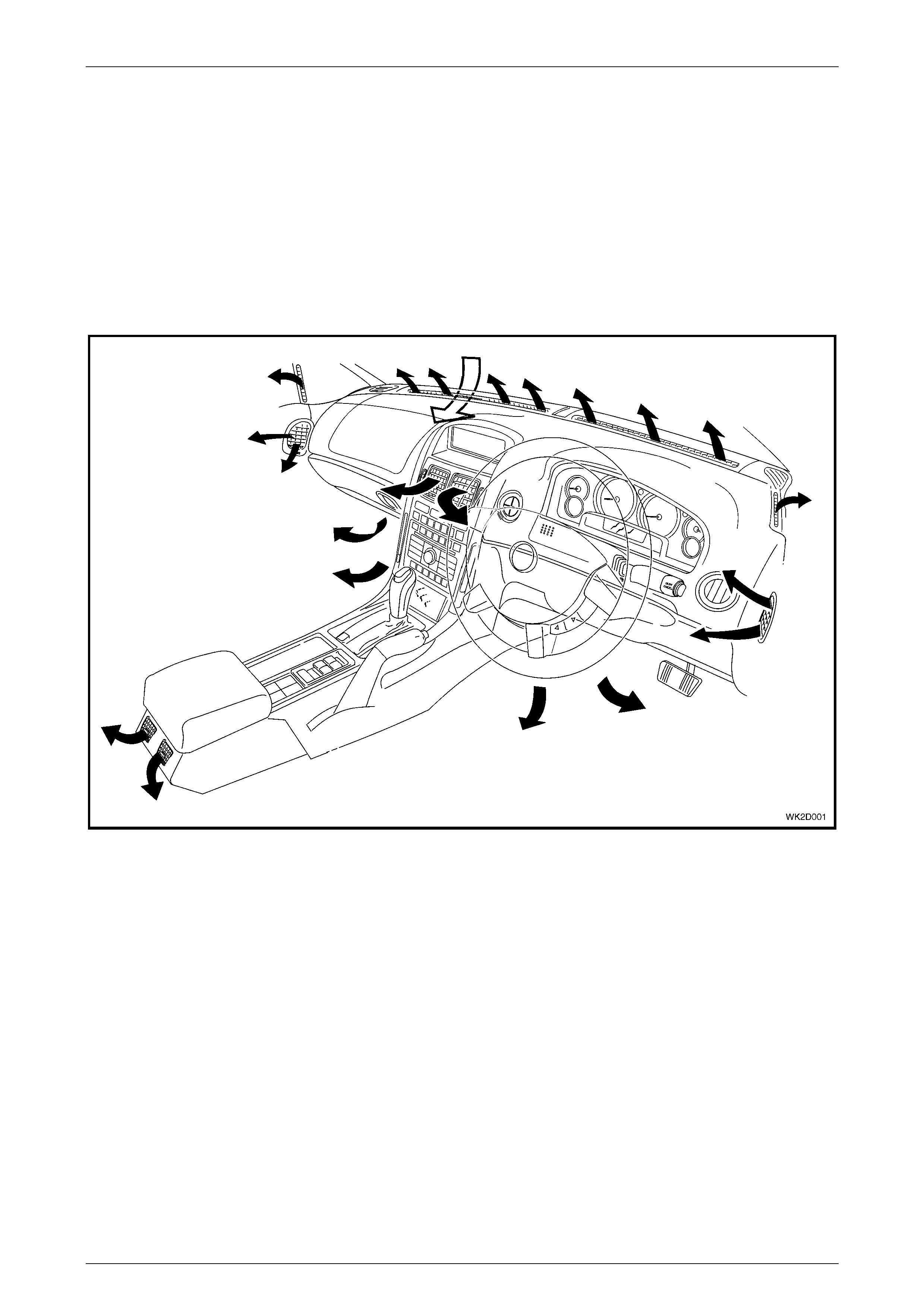
3.1 HVAC Inlet, Ducting And Outlets
The HVAC system inlet and ducting are identical to MY2003 VY Series models. For level 2 to 5 WK Series models, minor
design and appearance variations apply to the instrument panel centre ventilation outlet.
For more comprehensive information relating to the HVAC system inlet, ducting and outlets, refer to Section 2A,
2.1 HVAC INLET, DUCTS AND OUTLETS.
Figure 2D – 1 shows the HVAC system cabin outlets as applicable to level 2 to 5 WK Series models, which are fitted with
Occupant Climate Control (Auto A/C).
Figure 2D – 1
HVAC Occupant Climate Control (Auto A/C) – Description and Operation Page 2D–5
20–MAR–2003 Page 2D–5
3.2 OCC Control Module
The Occupant Climate Control (Auto A/C) system as fitted to MY2004 WK Level 2 to 5 vehicles uses an electronic ‘soft
touch’, push button type control module to select the desired HVAC functions, operating modes and cabin temperature.
Included in its functions are switches for windscreen demisting mode and the heated rear window. LED switch
illumination is provided when the windscreen demister and heated rear window are activated. All wording and icons on
the soft touch buttons are illuminated when the park lights are activated. Their illumination level is adjusted by the same
means and to the same level as the instrumentation illumination. The OCC control module’s active functions and
ventilation settings are displayed on the upper portion of the Multi Function Display (MFD) screen. An Outside
Temperature reading is also displayed in the centre of the MFD. Refer to 3.3 Multi Func tion Display for further
information on the construction and operation of the MFD.
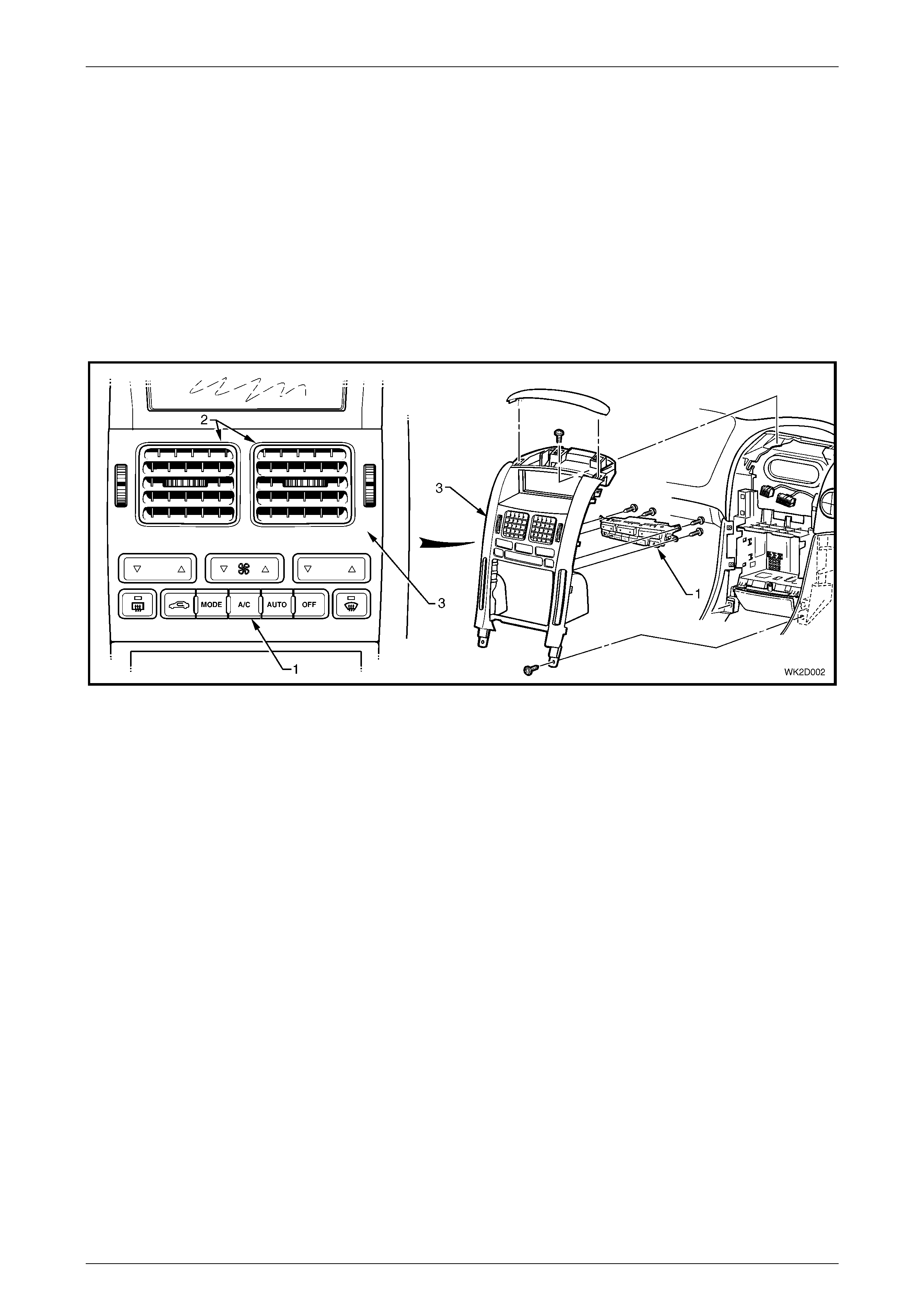
The OCC control module (1) is located below the face level centre vents (2) and is attached to the back of the instrument
panel centre trim (3) assembly at four points. Contained within the OCC module is all software required to control the
HVAC system in conjunction with the Body Control Module (BCM) and Powertrain Control Module (PCM).
Figure 2D – 2
Although different in appearance and configuration, the OCC control module as fitted to MY2004 WK Series models has
the same operating characteristics as the OCC control module as fitted to MY2003 VY and V2 Series models. For further
information on the operation of the OCC control module, refer to 4 OPERATION.
HVAC Occupant Climate Control (Auto A/C) – Description and Operation Page 2D–6
20–MAR–2003 Page 2D–6
OCC Control Module configurations
When LHD, RHD and styling configurations are taken into account, there are five different types of OCC control modules
fitted to MY2004 WK Level 2 to 5 vehicles.
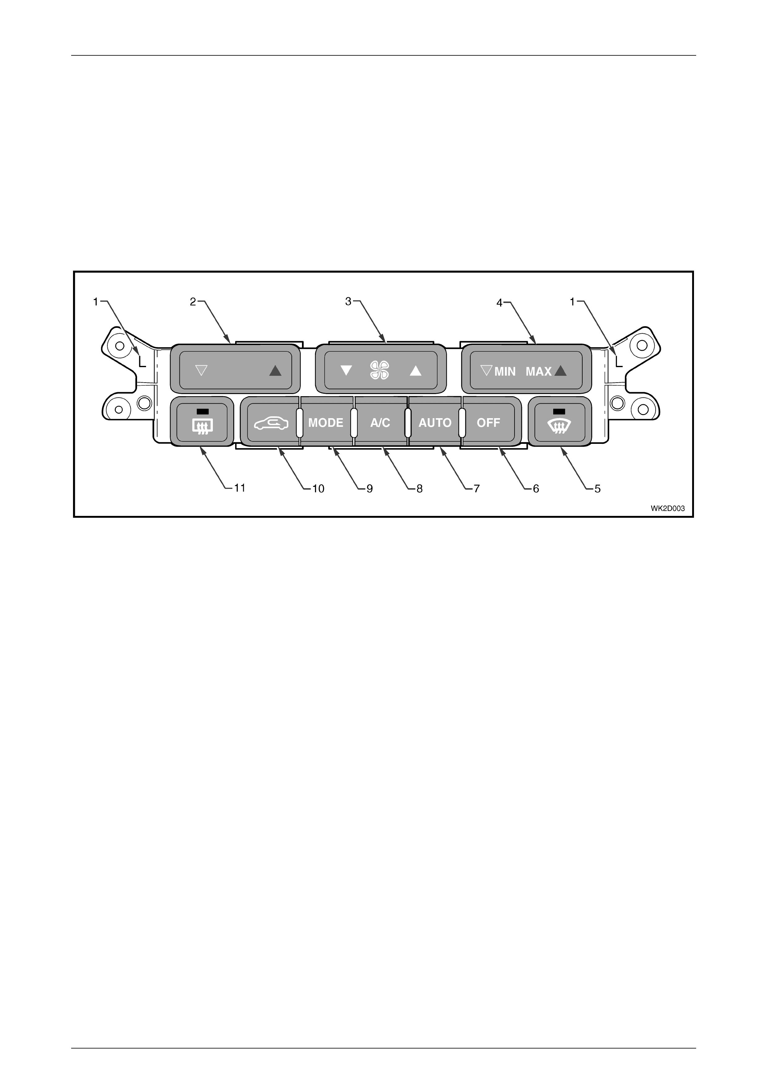
Left-hand drive
Figure 2D – 3 shows the configuration of the single zone OCC Control Module that is fitted to LHD Level 2 to 5 MY2004
WK Series models only. A Set Temperature switch is fitted to the driver’s side and a MIN / MAX switch is fitted to the
passenger side of the module.
Two ‘L’ markings on the mounting flanges indicate that the module is for LHD applications. The colour of the switches is
‘Dark Tempest’.
Figure 2D – 3
Legend
1 ‘L’ Indication for LHD Application 7 OCC System Aut omat ic Operati on Switc h
2 Set Temperature Switch 8 Air Conditioning On/Off Switch
3 Blower Fan Speed Switch 9 Ventilation Mode S el ection Switch
4 Min (Cold), Max (Hot) Uncontrolled Tem perature Setting 10 Fresh / Recirculation Mode Sel ection Switc h
5 Windscreen Demist Mode switc h and LED Indic ator 11 Heated Rear Window Switch and LED Indicator
6 OCC System Off Switch
HVAC Occupant Climate Control (Auto A/C) – Description and Operation Page 2D–7
20–MAR–2003 Page 2D–7
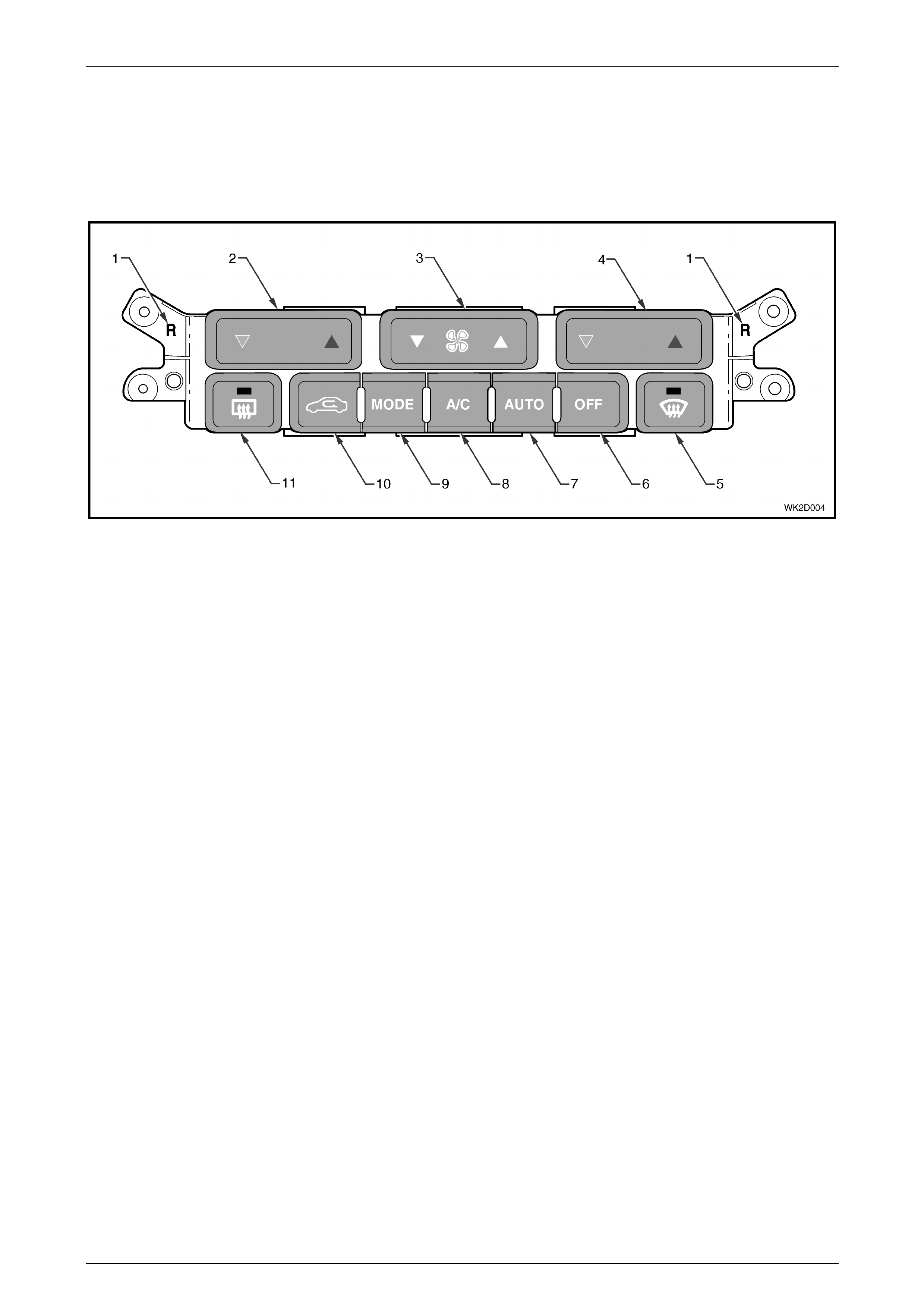
Right-hand drive
Figure 2D – 4 shows the configuration of the dual zone OCC Control Module that is fitted to RHD Level 2 to 5 MY2004
WK Series models. A Set Temperature switch is fitted to both the driver’s side and passenger side of the module.
Two ‘R’ markings on the mounting flanges indicate that the module is for RHD applications. The colour of the switches
may be ‘Grey Gold or ‘Dark Tempest’.
Figure 2D – 4
Legend
1 ‘R’ Indication for RHD Application 7 OCC System Aut omat ic Operati on Switch
2 Passenger Si de Set Temperature Switch 8 Air Conditi oni ng On/Off Switch
3 Blower Fan Speed Switch 9 Ventilation Mode S el ection Switch
4 Driver’s Si de Set Temperature Switc h 10 Fresh / Recirculation Mode Sel ection Switch
5 Windscreen Demist Mode switc h and LED Indic ator 11 Heated Rear Window Switch and LED Indicator
6 OCC System Off Switch
HVAC Occupant Climate Control (Auto A/C) – Description and Operation Page 2D–8
20–MAR–2003 Page 2D–8
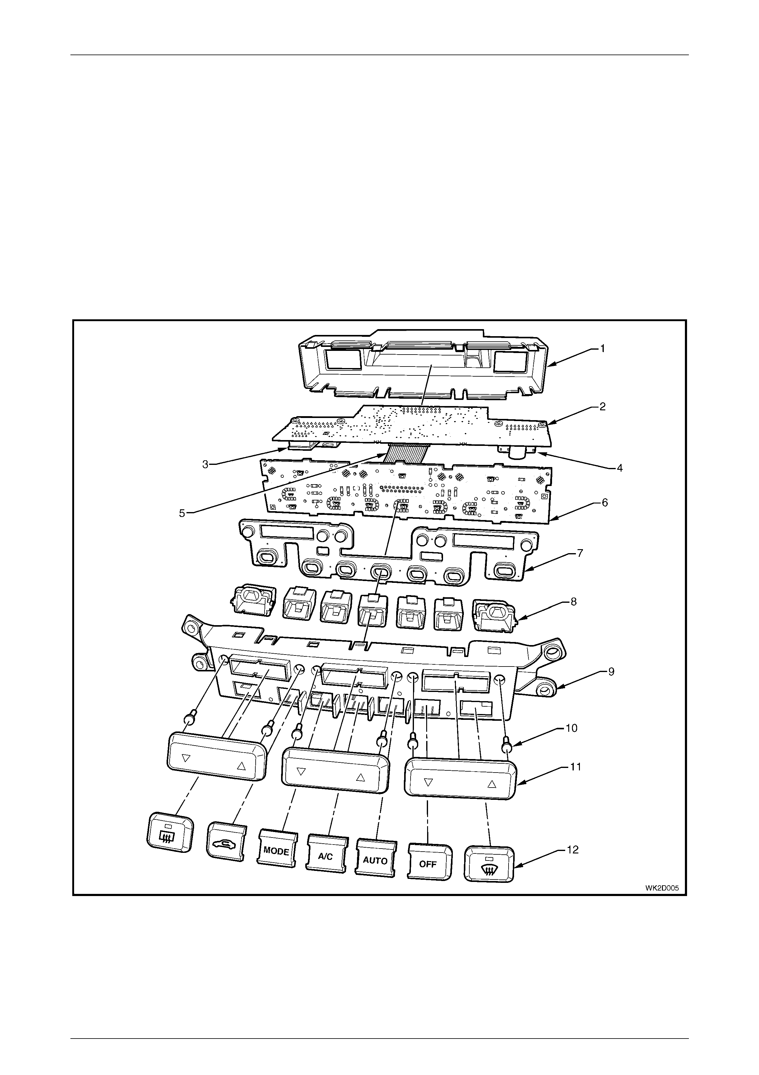
OCC Control Module components
The module is designed for ease of assembly and no screws are used in its construction aside from those used to install
the two electrical connectors to the rear circuit board. The front housing and rear housing of the module are constructed
of plastic. The ten control buttons are also plastic and clip into and are retained by the front module housing. The front
housing clips over and locks to the rear housing at eight locations. Contained within the module are two printed circuit
boards. Information from the front circuit board is transferred to the rear circuit board through a ribbon cable. A 16-pin
and a 20-pin electrical connector are secured by screws directly to the underside of the rear of the circuit board and
protrude through apertures of the module’s rear housing. The front circuit board is installed vertically and is clipped to the
front housing in six location s. The rear circuit board is installed horizontally into two internal locating slots either side of
the front housing. The rear circuit board is locked into position when the front housing and rear housings of the module
are assembled. The complete module is mounted to the rear of the instrument centre trim at two flanges moulded either
side of the front housing and is retained by four screws. The lower mounting screws of the module also retain the upper
mounts of the cup holders, which are also assembled to the back of the centre instrument panel.
There are no replaceable bulbs contained within the OCC control module. LEDs are used to provide illumination where
necessary. The module has no serviceable items. If any component fails to function, the module must be replaced.
Figure 2D – 5
Legend
1 Rear Module Housing 4 X2 Connector 7 Silicone Switches 10 Upper Switch Relay Pins
2 Rear Circuit Board 5 Ribbon Cable 8 Lower Switch Housings 11 Upper Switch Fascias
3 X1 Connector 6 Front Circuit Board 9 Front Module Housing 12 Lower Switch Fascias
HVAC Occupant Climate Control (Auto A/C) – Description and Operation Page 2D–9
20–MAR–2003 Page 2D–9
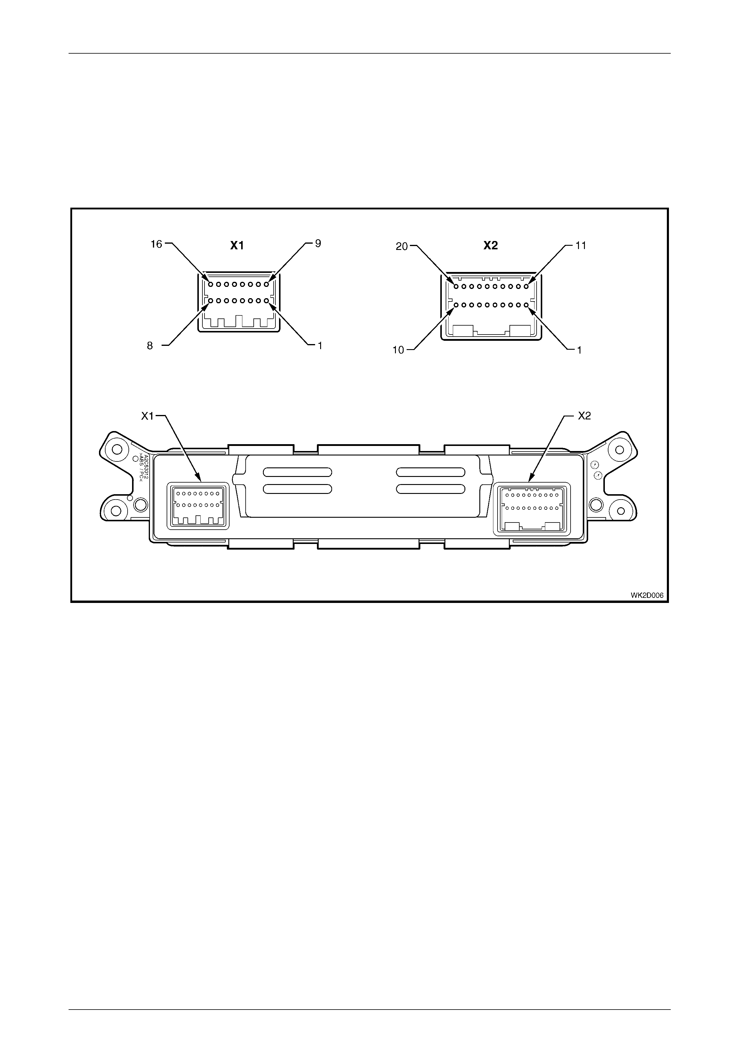
OCC Control Module electrical connection
Two electrical connectors are located to the rear of the OCC control module. In accordance with the Integrated Vehicle
Electrical Design (IVED) standard as applied to MY 2004 W K Series vehicles, the module is designated as A14 and the
connectors are designated as Connector X1 and Connector X2. Both connectors are screw mounted to the underside of
the rear printed circuit board.
Figure 2D – 6 provides a view of the connector terminal assignments and the tables following it provide information on
their function.
Figure 2D – 6

HVAC Occupant Climate Control (Auto A/C) – Description and Operation Page 2D–10
20–MAR–2003 Page 2D–10
Connector X1 – LHD and RHD
Pin Number Wire Colour Function
X1-1 Yellow MFD – Ambient temperature display (CAN_HI)
X1-2 – Not connected
X1-3 Green / White Serial data line
X1-4 Blue / Black In-car temperature signal
X1-5 Light Green / Black Ambient air temperature signal
X1-6 Pink / Blue Fuse F13 – Power from IGN
X1-7 Black / Yellow Ground (X157)
X1-8 Orange / Yellow Fuse F21 – Power from battery
X1-9 Brown MFD – Ambient temperature display (CAN_LO)
X1-10 – Not connected
X1-11 Green Rear remote control – Fan speed and temp adjust
X1-12 Yellow Fan speed feedback
X1-13 Brown / White Fuse F11 – Power for instrument illumination
X1-14 Yellow / Black Fan speed high – Blower relay
X1-15 Black / Red Fan speed control
X1-16 Black / Red Rear window demister select to HRW relay

HVAC Occupant Climate Control (Auto A/C) – Description and Operation Page 2D–11
20–MAR–2003 Page 2D–11
Connector X2 – LHD
Pin Number Wire Colour Function
X2-1 Red Air mix door motor + ve
X2-2 Black Air mix door motor – ve
X2-3 – Not connected
X2-4 – Not connected
X2-5 Red / White Power for solenoid pack solenoids and water VSV
X2-6 Dark Green Foot 1 select – No. 1 solenoid, solenoid pack
X2-7 Black / White Defog select – No. 2 solenoid, solenoid pack
X2-8 Pink Fresh / recirc select – No. 5 solenoid, solenoid pack
X2-9 Yellow Face 1 select – No. 4 solenoid, solenoid pack
X2-10 Blue / Red Face 2 select – No. 3 solenoid, solenoid pack
X2-11 Brown Power for air mix motor position signal
X2-12 – Not connected
X2-13 – Not connected
X2-14 – Not connected
X2-15 White Ground for sensors and air mix motor signal
X2-16 – Not connected
X2-17 – Not connected
X2-18 Green / White Air mix motor position signal
X2-19 White / Black Evaporative temperature sensor signal
X2-20 Red / Black Water valve – Vacuum switch valve

HVAC Occupant Climate Control (Auto A/C) – Description and Operation Page 2D–12
20–MAR–2003 Page 2D–12
Connector X2 – RHD
Pin Number Wire Colour Function
X2-1 Red Driver’s side air mix door motor + ve
X2-2 Black Driver’s side air mix door motor – ve
X2-3 Brown Passenger side air mix door motor + ve
X2-4 Blue Passenger side air mix door motor – ve
X2-5 Red / White Power for solenoid pack solenoids
X2-6 Dark Green Foot 1 select – No. 4 solenoid, solenoid pack
X2-7 Black / White Foot 2 select – No. 5 solenoid, solenoid pack
X2-8 Pink Fresh/recirculation select – No. 1 solenoid, solenoid pack
X2-9 Yellow Face 1 select – No. 2 solenoid, solenoid pack
X2-10 Blue / Red Face 2 select – No. 3 solenoid, solenoid pack
X2-11 White Power for air mix motor position signal
X2-12 – Not connected
X2-13 – Not connected
X2-14 – Not connected
X2-15 Tan Ground for sensors and air mix motor signals
X2-16 – Not connected
X2-17 Yellow / Blue Passenger side air mix motor position signal
X2-18 Green / White Driver’s side air mix motor position signal
X2-19 White / Black Evaporative temperature signal
X2-20 Purple Water valve – No. 6 solenoid, solenoid pack
HVAC Occupant Climate Control (Auto A/C) – Description and Operation Page 2D–13
20–MAR–2003 Page 2D–13
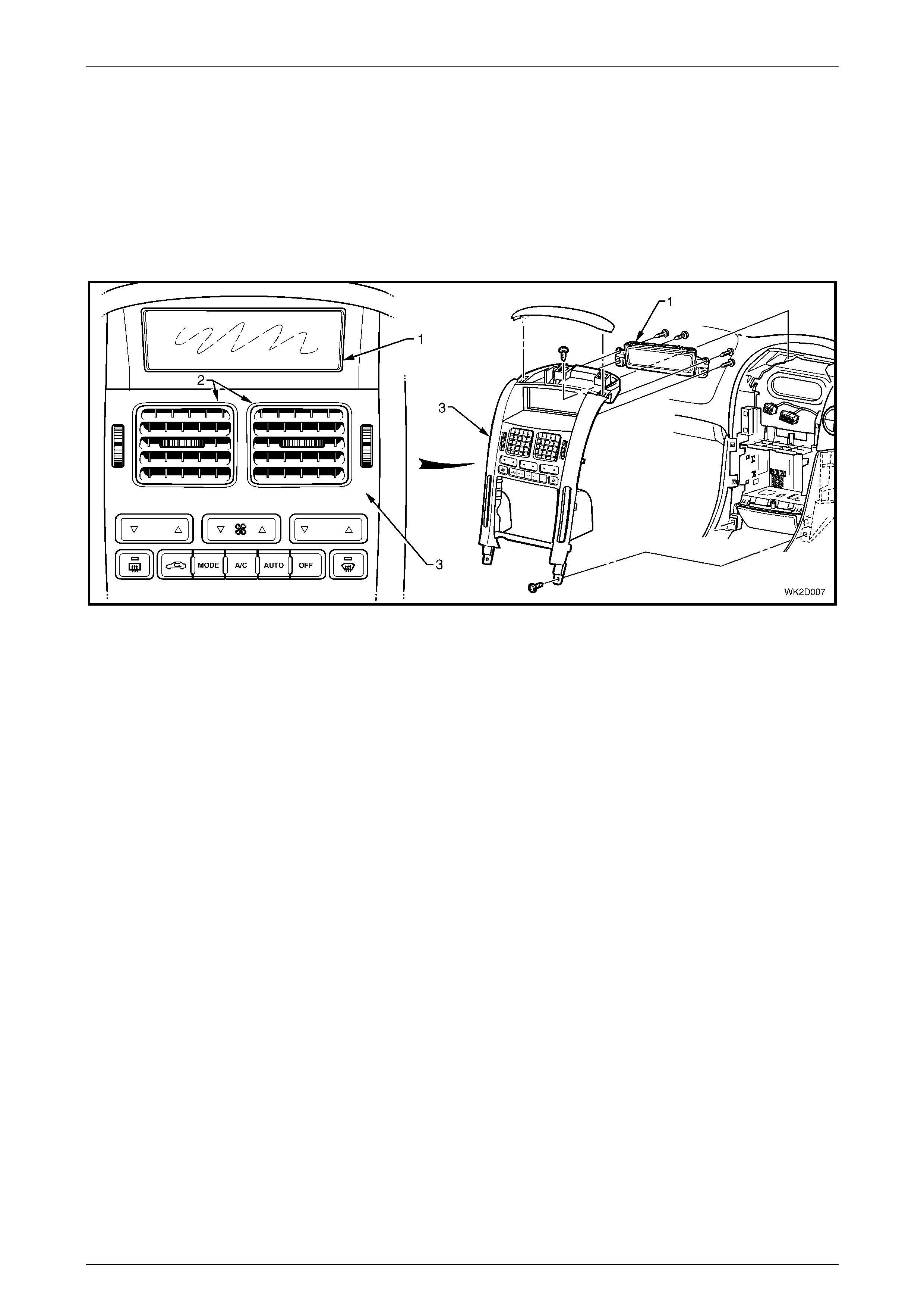
3.3 Multi Function Display
The OCC control module’s active functions and ventilation settings are displayed on the upper portion of the Multi
Function Display (MFD) screen. This includes an outside temperature function, which is displayed whenever the ignition
is on. The MFD is also used to display current time and audio system settings. These are displayed on the lower portion
of the MFD screen. A line running across the screen of the MFD divides these two groups of information. In the event
that the OCC system develops a fault there is no self-diagnostic symbol displayed on the MFD.
The MFD (1) is located above the face level centre vents (2) and is attached to the back of the instrument panel centre
trim assembly (3) at four points.
Figure 2D – 7
HVAC Occupant Climate Control (Auto A/C) – Description and Operation Page 2D–14
20–MAR–2003 Page 2D–14
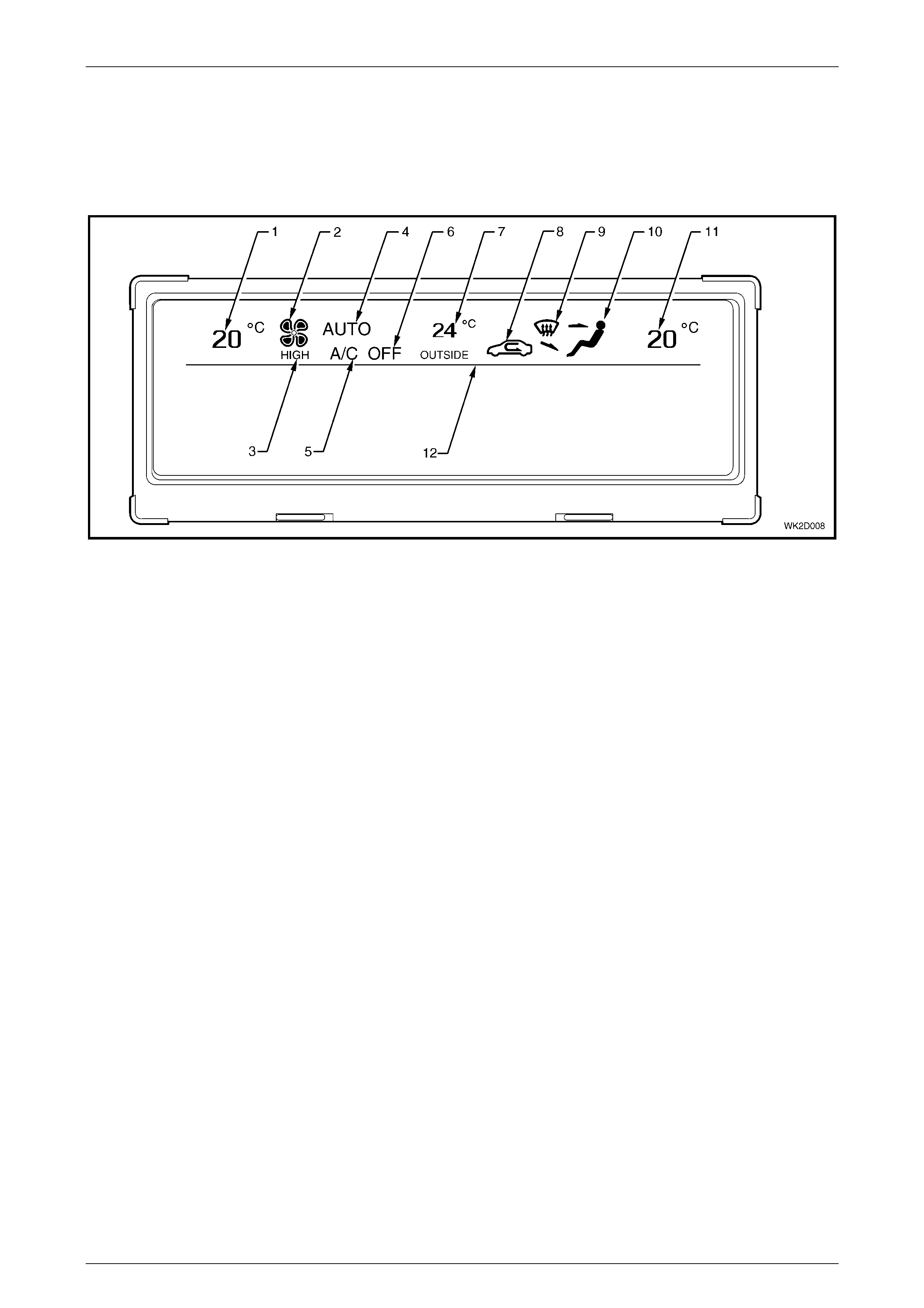
Multi Functi on Di splay graphics
Figure 2D – 8 shows the Multi Function Display (MFD) Module that is fitted to all LHD and RHD Level 2 to 5 MY2004 WK
Series models. The icons and information above the separation line are devoted to OCC (Auto A/C) functions and
information. Displays below the separation line relate to entertainment system functions as well as time and date
information. For further information on the MFD refer to Section 12I, MULTI FUNCTION DISPLAY.
Figure 2D – 8
Legend
1 Left-hand Side Temperature Setti ng 7 Outside of Vehicle Temperature Indicator
2 Blower Fan 1, 2, 3, and 4 Speed Indicator 8 Recircul ation Mode Active I ndic ator
3 Blower Fan Maximum Speed Indicator 9 Windscreen Demist Mode Acti ve Indicat or
4 OCC System In Auto Mode Indicator 10 Foot / Face/ Bi-level Ventilation Mode Indicator
5 Air Conditi oni ng On Indicator 11 Right-hand Side Temperature Setting
6 Air Conditi oni ng Off Indicator 12 Audio / Time / Date Display and HVAC Display Separati on Li ne
HVAC Occupant Climate Control (Auto A/C) – Description and Operation Page 2D–15
20–MAR–2003 Page 2D–15
3.4 Rear Remote Control
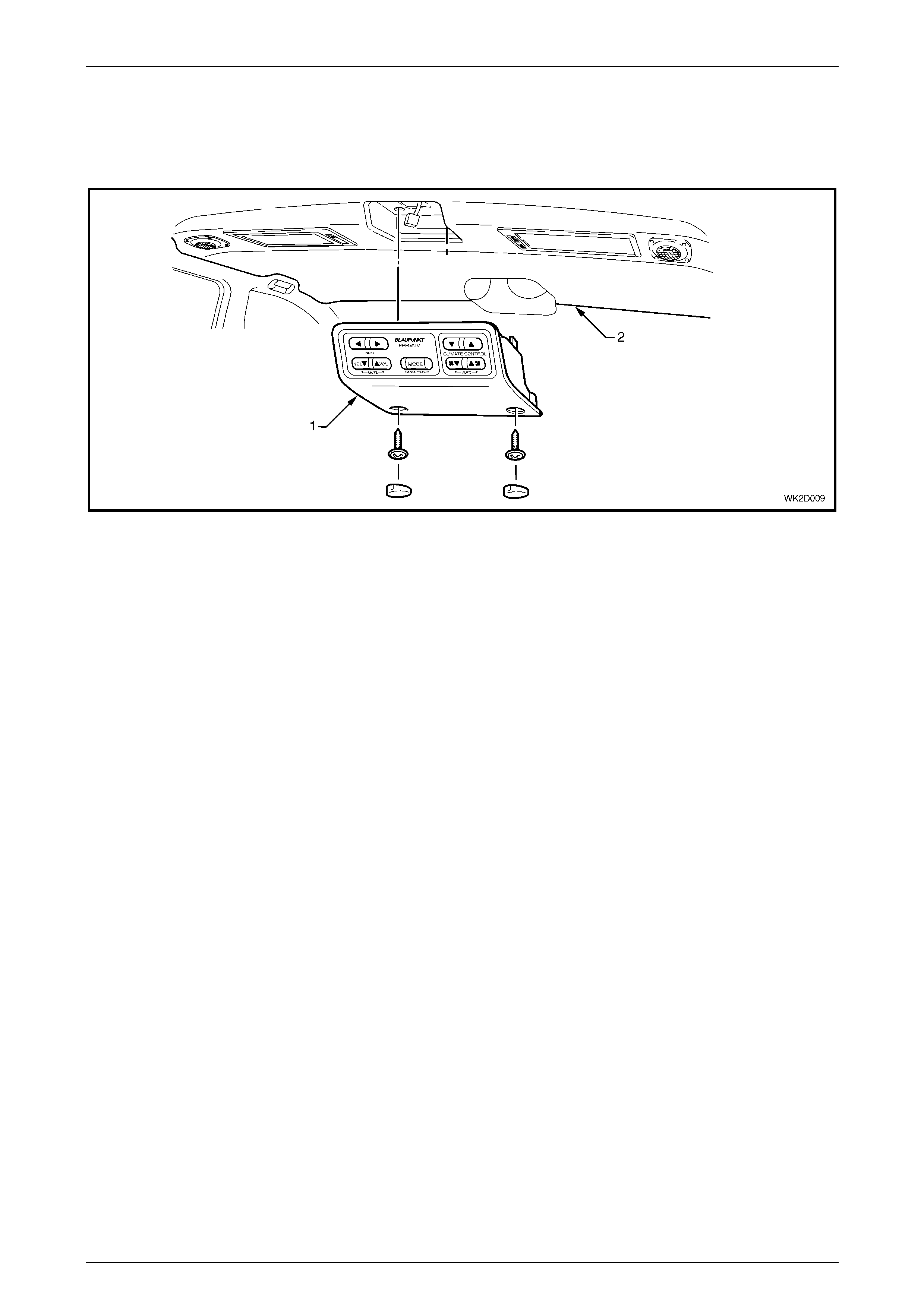
On Level 5 MY2004 WK Series vehicles, rear passengers can access a rear remote control (1), which is fitted to the
centre of the headlining (2) forward of the rear passenger compartment.
Figure 2D – 9
This unit combines a number of entertainment system functions with the following Occupant Climate Control functions.
• Temp Up
• Temp Down
• Fan Up
• Fan Down
Pressing any one of these switches will turn the system on. Pressing the Fan Up and Fan Down switches simultaneously
for less than two seconds will switch the HVAC system to AUTO mode. The fan speed, temperature setting and vent
settings will then be controlled automatically.
Holding down the same switches for more than two seconds will ‘link’ the OCC system meaning that the front passenger
temperature setting will match that of the driver’s side. When the system is linked, changes made at the rear remote
switches alter the air from the driver’s vents, front passenger’s vents and rear passenger vents. If the system is not
linked, changes made at the rear remote switches alter air from the driver’s vents and rear passenger vents only. The
linking function is applicable only to RHD drive models onl y as dual zone systems are not fitted LHD models.
HVAC Occupant Climate Control (Auto A/C) – Description and Operation Page 2D–16
20–MAR–2003 Page 2D–16
Each switch has a unique resistance value. The OCC control module uses this resistance value to determine which
switch has been pressed and alters the HVAC settings accordingly. The HVAC system cannot be turned off at the rear
remote control.
For further information on the operation of the OCC (Auto A/C) system, refer to Section 2D, 4 OPERATION in the
MY2003 VY and V2 Series Service Information.
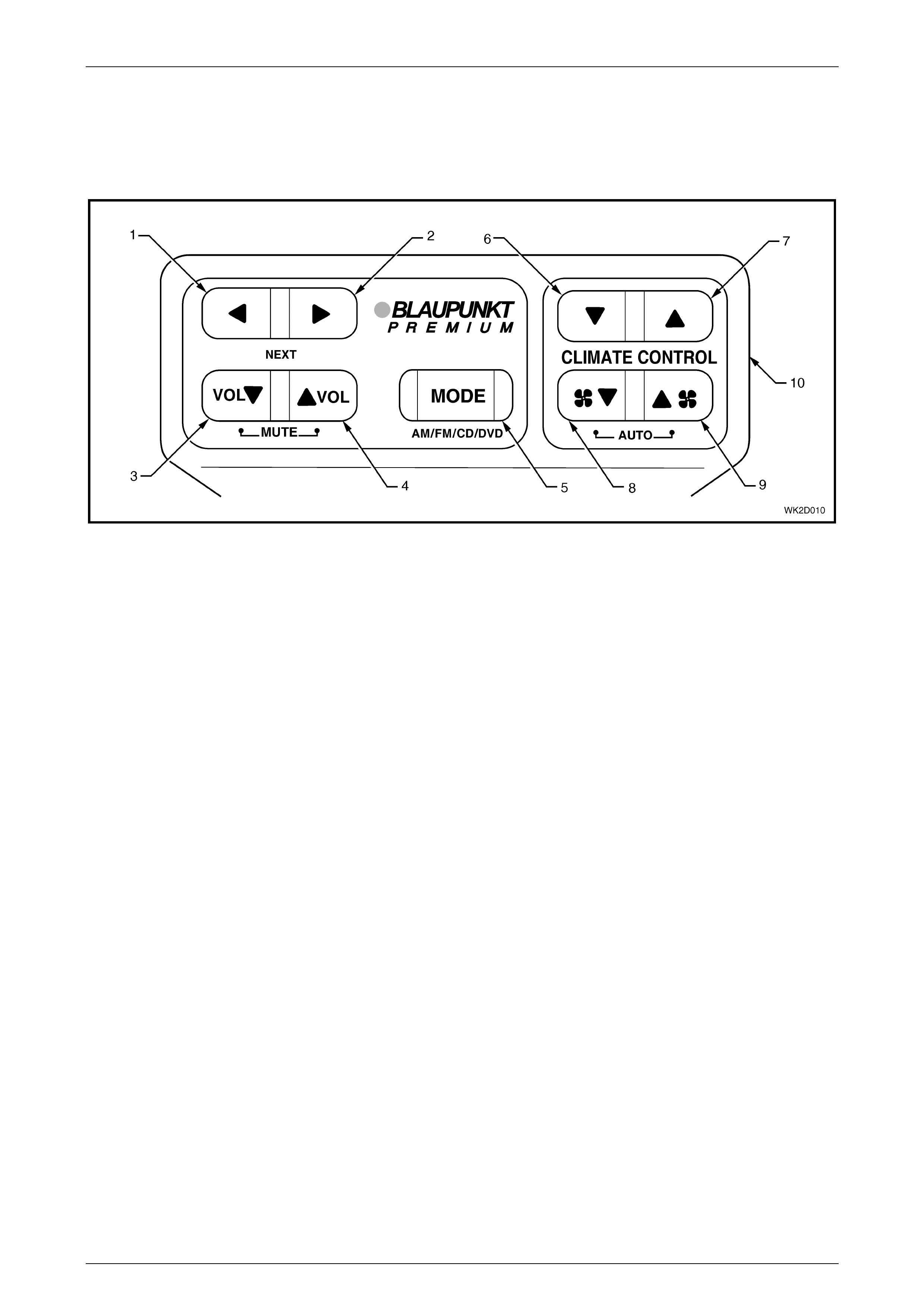
Figure 2D – 10
Legend
1 Next Track / Station Back Switch 6 Temperature Down Switch
2 Next Track / Station Forward Switch 7 Temperature Up Switch
3 Volume Down Switch 8 Blower Fan Speed Down Switch
4 Volume Up Switch 9 Blower Fan Speed Up Switch
5 Mode Switch – AM / FM Radio, CD Player or DVD Player 10 Front Fascia / Housing
HVAC Occupant Climate Control (Auto A/C) – Description and Operation Page 2D–17
20–MAR–2003 Page 2D–17
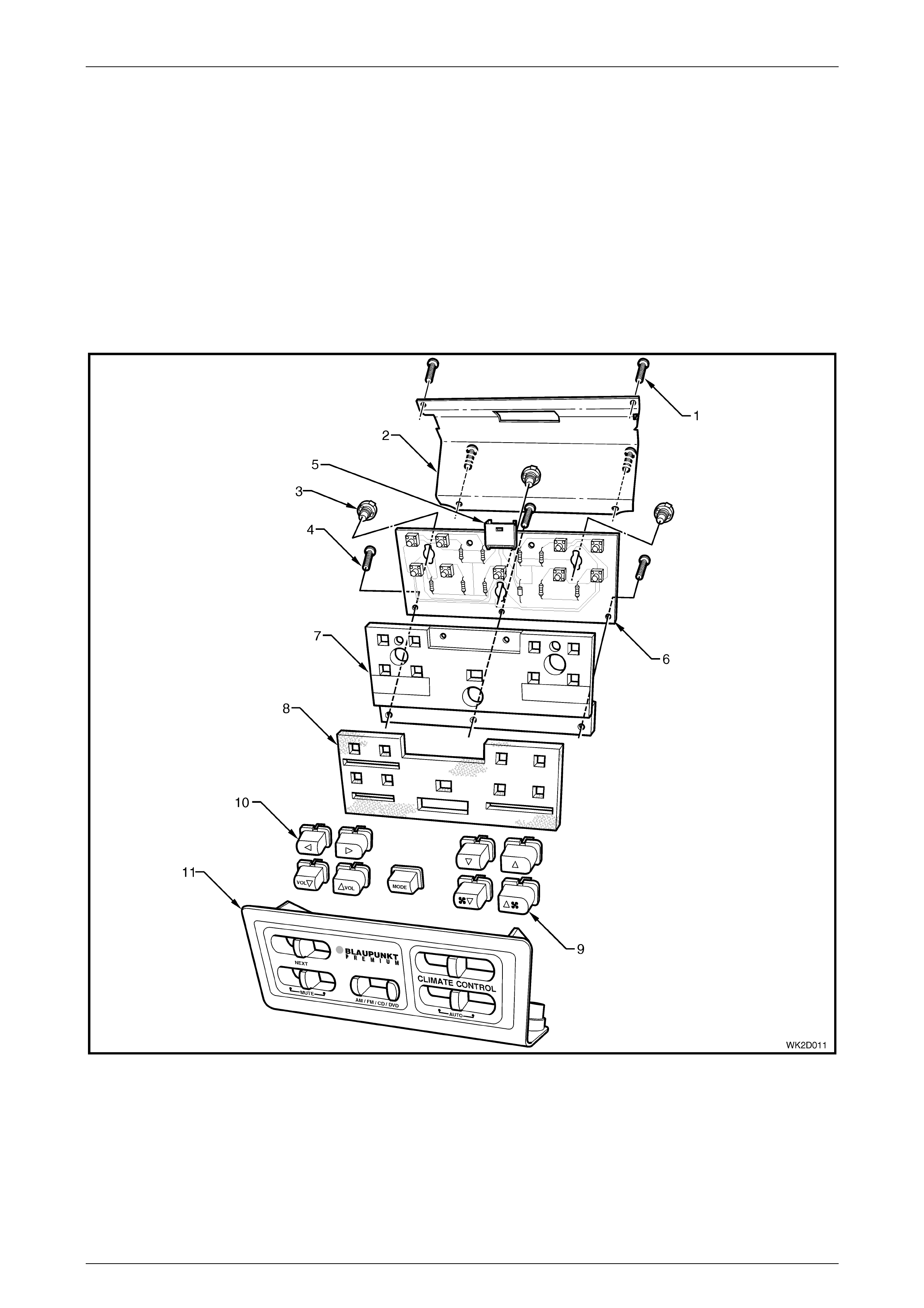
Rear Remote Control components
The rear remote control housing is constructed of plastic and forms the front fascia and sides of the unit. Nine switches
(five audio and four HVAC) are held in location by the same three screws used to assemble the circuit board, the
illumination plate and foam piece to the housing. A single, six terminal electrical connector is bonded to the top of the
circuit board and protrudes through an aperture in the metallic rear cover. The rear cover is attached to the housing by
four screws.
The complete unit is attached to the headlining by two integral hooks, formed as part of the top of the rear cover, and two
screws installed to the underside of the front housing. These screws can be accessed by removing the two plastic cover
plugs used to conceal them.
The three bulbs used to provide illumination can be serviced when the complete unit has been removed from the
headlining and rear cover is detached. No other item of the unit is serviced. If a component fails, excluding the
illumination bulbs, the complete unit must be replaced.
Figure 2D – 11
Legend
1 Rear Cover Screws 5 X1 Connector 9 HVAC System Switc hes
2 Rear Cover 6 Circuit Board 10 Entert ai nment Syst em S witches
3 Bulbs 7 Illumi nation Plat e 11 Front Fascia / Housing
4 Internal Screws 8 Foam Piece
HVAC Occupant Climate Control (Auto A/C) – Description and Operation Page 2D–18
20–MAR–2003 Page 2D–18
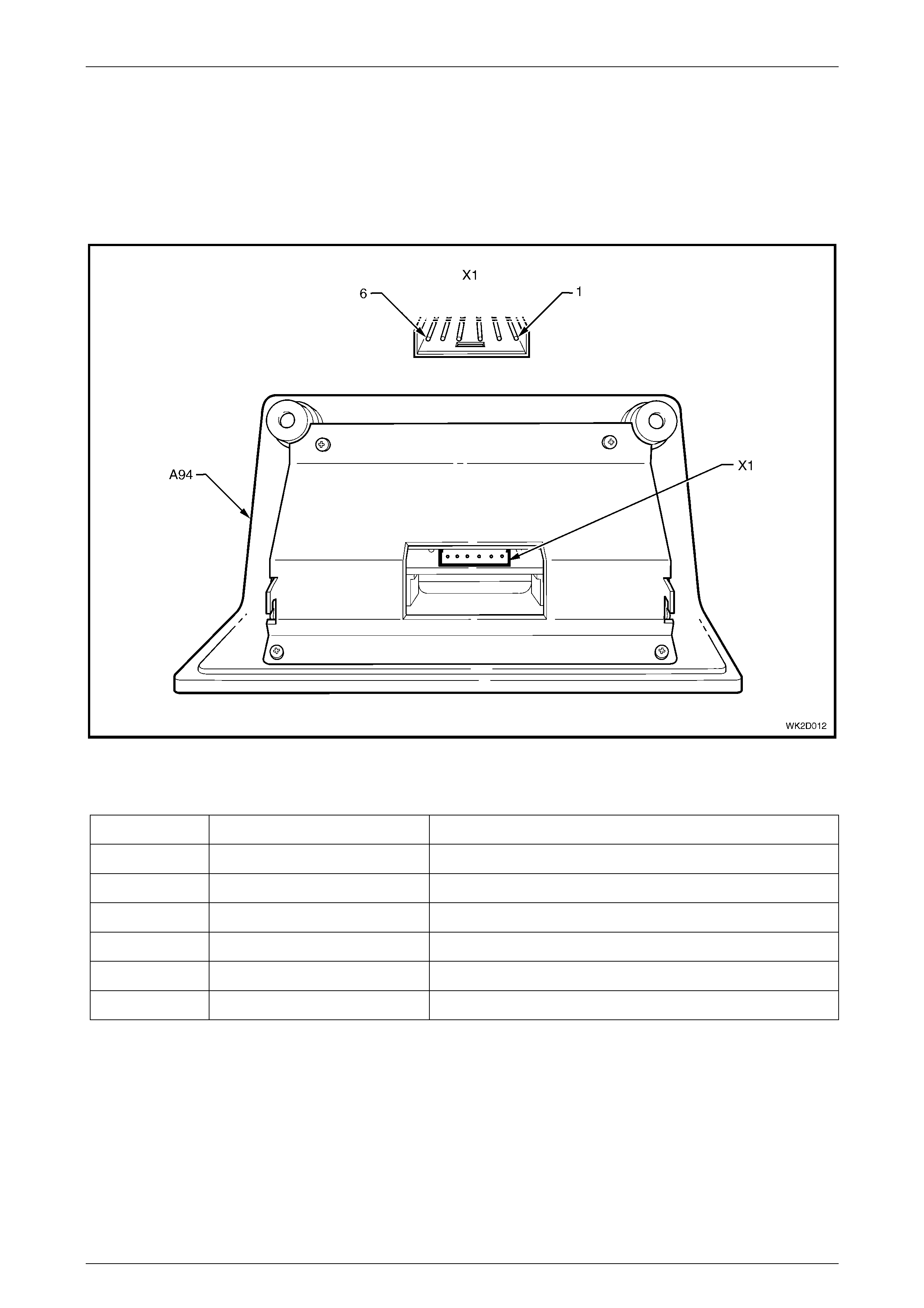
Rear Remote Control electrical connection
One electrical connector is located to the rear of the rear remote control. In accordance with the Integrated Vehicle
Electrical Design (IVED) standard as applied to MY 2004 WK Series vehicles, the control is designated as A94 and the
connector is designated as Connector X1. The connector is bonded to the front of the printed circuit board.
Figure 2D – 12 provides a view of the connector terminal assignments and the tables following it provide information on
their function.
Figure 2D – 12
Connector X1 – LHD and RHD
Pin Number Wire Colour Function
X1-1 Green Switch Signal – to OCC control module
X1-2 Black / Red Ground – OCC control module switch signal (X157)
X1-3 Yellow Fuse F16 – Power from IGN for illumination
X1-4 Black / Blue Ground (X118) – illumination
X1-5 W hite Switch Signal – to Audio Head Unit (AHU)
X1-6 Black / Yellow Ground – AHU switch signal (X118)

HVAC Occupant Climate Control (Auto A/C) – Description and Operation Page 2D–19
20–MAR–2003 Page 2D–19
4 Operation
The functionality, operating procedures and recommended settings of the HVAC Occupant Climate Control (Auto A/C)
system as fitted to Level 2 to 5 MY2004 WK Series models are essentially the same as those for single zone and dual
zone OCC (Auto A/C) systems as fitted to MY2003 VY and V2 Series models, noting the following:
• All HVAC OCC (Auto A/C) settings are displayed on the upper section of the Multi Function Display (refer to
Figure 2D – 8) as opposed to a dedicated and integral LCD display as fitted to MY2003 VY and V2 Series models.
For further information on the MFD, refer to Section 12I, MULTI FUNCTION DISPLAY.
• The Outside Temperature function is not selectable. The outside temperature remains displayed in the centre of
the Multi Function Display (refer to item 7 in Figure 2D – 8) whenever the HVAC Occupant Climate Control
(Auto A/C) system is operating.
• On Level 5 MY2004 WK Series models, the system temperature, blower fan speed and Auto On/Off functions can
also be controlled by the rear seat passengers via the rear remote control. For further information on the rear
remote control including a brief description of its operation, refer to 3.4 Rear Remote Control.
For further information relating to the operation of the HVAC Occupant Climate Control (Auto A/C) as fitted to Level 2 to 5
MY2004 WK Series models, refer to Section 2D, 4 OPERATION in the MY2003 VY and V2 Series Service Information.

HVAC Occupant Climate Control (Auto A/C) – Description and Operation Page 2D–20
20–MAR–2003 Page 2D–20
5 Specifications
For all specifications relating to the HVAC Occupant Climate Control (Auto A/C) as fitted to Level 2 to 5 MY2004
WK Series models, refer to Section 2D, 5 SPECIFICATIONS in the MY2003 VY and V2 Series Service Information.