
HVAC Occupant Climate Control (Auto A/C) – Removal and Installation Page 2E–1
20–MAR–2003 Page 2E–1
Section 2E
HVAC Occupant Climate Control (Auto A/C) –
Removal and Installation
ATTENTION
Before performing any Service Operation or other procedure described in this Section, refer to Section 00
WARNINGS, CAUTIONS AND NOTES for correct workshop practices with regard to safety and/or property
damage.
1 General Information............................................................................................................................... 2
2 Service Operations................................................................................................................................3
2.1 OCC Control Module..............................................................................................................................................3
Remove ...................................................................................................................................................................3
Install.......................................................................................................................................................................6
2.2 Multi Function Display...........................................................................................................................................7
Remove and Install.................................................................................................................................................7
2.3 Rear Remote Control .............................................................................................................................................8
Remove ...................................................................................................................................................................8
Install.......................................................................................................................................................................8
2.4 Centre Air Outlet Housing .....................................................................................................................................9
Remove and Install.................................................................................................................................................9
2.5 Occupant Climate Control (Auto A/C) HVAC unit..............................................................................................10
Remove and Install...............................................................................................................................................10
3 Torque Wrench Specifications........................................................................................................... 11
4 Special Tools........................................................................................................................................ 12
Techline
Techline
Techline
Techline

HVAC Occupant Climate Control (Auto A/C) – Removal and Installation Page 2E–2
20–MAR–2003 Page 2E–2
1 General Information
The information that is provided in this Section applies only to Level 2 to 5 MY2004 WK Series models. It is to be used
for both left and right-hand drive vehicles. Although the information shown is primarily right-hand drive, it is also
applicable to left-hand drive vehicles unless otherwise specified.

HVAC Occupant Climate Control (Auto A/C) – Removal and Installation Page 2E–3
20–MAR–2003 Page 2E–3
2 Service Operations
IMPORTANT
All fasteners are important attaching parts as they affect the performance of vital components and / or could
result in major repair expense. Where specified in this section, fasteners MUST be replaced with parts of the
same part number or a GM approved equivalent. Do not use fasteners of an inferior quality or substitute
design.
Torque values must be used as specified during reassembly to ensure proper retention of all components.
Through out this section, fastener torque wrench specifications may be accompanied with the following
identification marks:
+
++
+ Fasteners must be replaced after loosening.
&
&&
& Vehicle must be at kerb height before final tightening.
6
66
6 Fasteners either have micro encapsulated sealant applied or incorporate a mechanical thread lock and
should only be re-used once. If in doubt, replacement is recommended.
If one of these identification marks is present alongside a fastener torque wrench specification, the
recommendation regarding that fastener must be adhered to.
2.1 OCC Control Module
LT Section – 08-155A
Remove
1 If required, remove the following navigation system equipment:
a Remote control cradle, refer to Section 12L NAVIGATION SYSTEM in the MY2004 WK Series Service
Information.
b Navigation monitor escutcheon, refer to Section 12L NAVIGATION SYSTEM in the MY 2004 WK Series
Service Information.
2 Remove the floor console cover assembly, refer to Section 1A3, 2.1 FLOOR CONSOLE COVER ASSEMBLY in the
MY2003 VY and V2 Series Service Information.
HVAC Occupant Climate Control (Auto A/C) – Removal and Installation Page 2E–4
20–MAR–2003 Page 2E–4
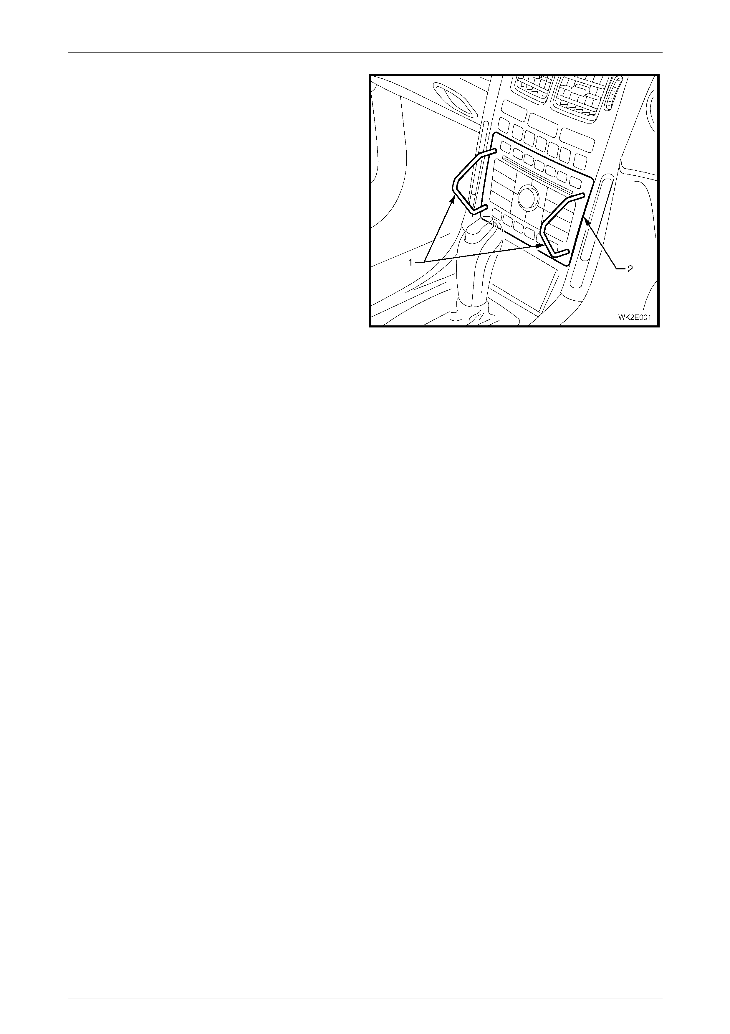
3 Insert Special Tool KM6067 (1) into the holes each
side of the radio assembly (2).
4 While holding outward pressure on the tools (toward
each outer side of the vehicle), pull the radio assembly
from the radio housing.
NOTE
The wiring connectors remain attached to the
radio housing and will disconnect on removal of
the radio assembly.
Figure 2E – 1
HVAC Occupant Climate Control (Auto A/C) – Removal and Installation Page 2E–5
20–MAR–2003 Page 2E–5
Using tools to prise off components may
damage the instrument panel, the instrument
panel upper centre trim panel and/or the
centre trim assembly.
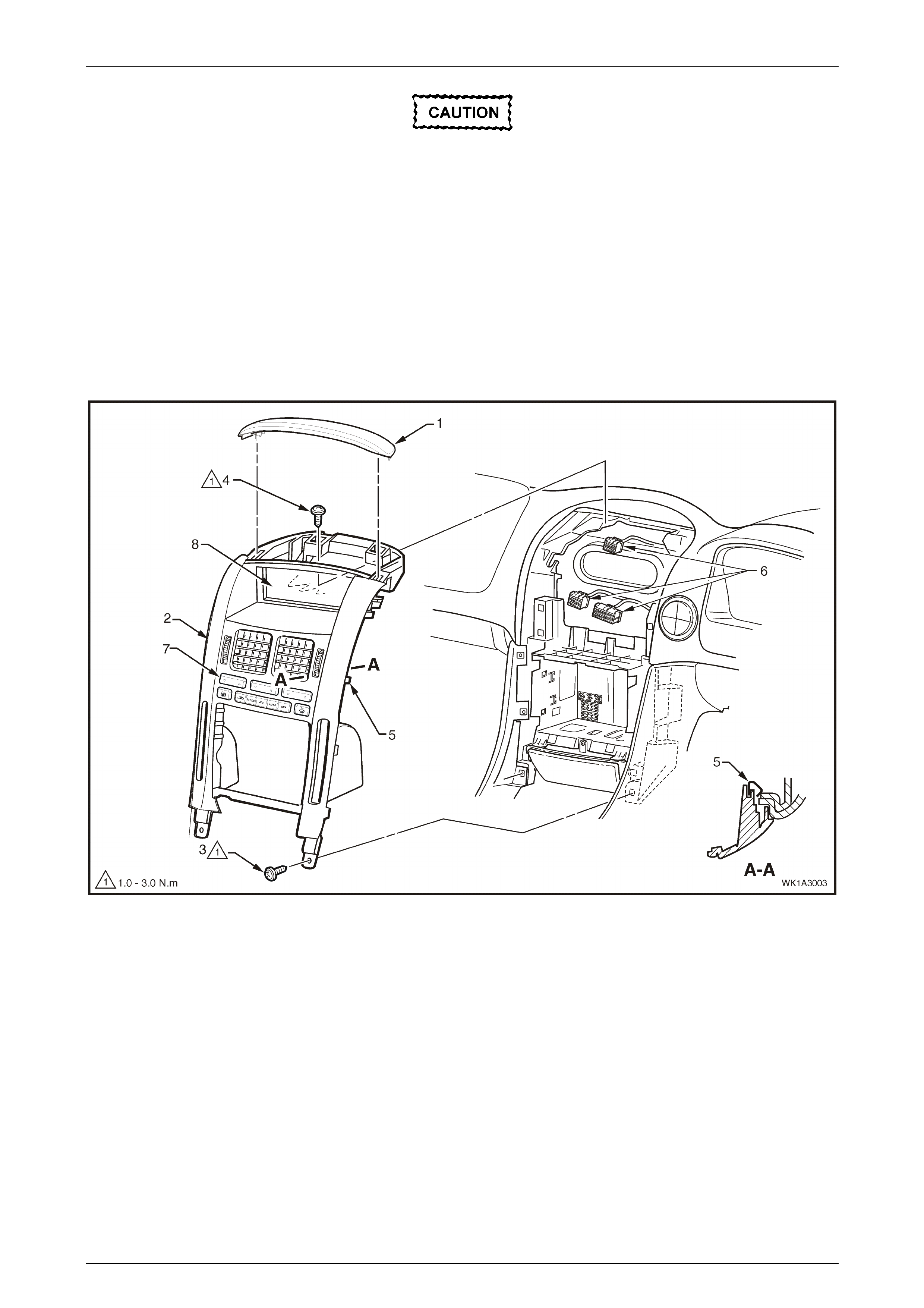
5 Carefully prise the front edge of the instrument panel upper centre trim panel (1), and pull upward to disengage the
retaining clips at each corner from the centre trim assembly (2), refer to Figure 2E – 2.
6 Remove the lower screws (3), two places, attaching the centre trim assembly to the instrument panel.
7 Remove the upper screws (4), two places, attaching the centre trim assembly to the instrument panel.
8 Remove the centre trim assembly, disengaging the four clips (5), far enough to disconnect the wiring connectors (6)
from the rear of the OCC control module (7) and multi function display (8).
9 Remove the centre trim assembly.
Figure 2E – 2

HVAC Occupant Climate Control (Auto A/C) – Removal and Installation Page 2E–6
20–MAR–2003 Page 2E–6
10 Remove the screw (1), one place each side, attaching the OCC control module (2) and cup holder assembly (3) to
the centre trim (4), refer to Figure 2E – 3.
11 Remove the screw (5), one place each side, attaching the OCC control module to the centre trim and remove the
control modu le.
Figure 2E – 3
NOTE
For diagnosis of the OCC control module refer to
Section 2F HVAC OCCUPANT CLIMATE
CONTROL (AUTO A/C) – DIAGNOS TICS.
Install
Installation of the OCC control module is the reverse order of removal procedures, noting the following:
1 Tighten all screws to the specified torque.
OCC control module attaching screw
torque specific atio n ...................................1.0 – 3.0 N.m
Instrument panel centre trim assembly
attaching screw torque specification.......... 1.0 – 3.0 N.m

HVAC Occupant Climate Control (Auto A/C) – Removal and Installation Page 2E–8
20–MAR–2003 Page 2E–8
2.3 Rear Remote Control
LT Section – 09-500
Remove
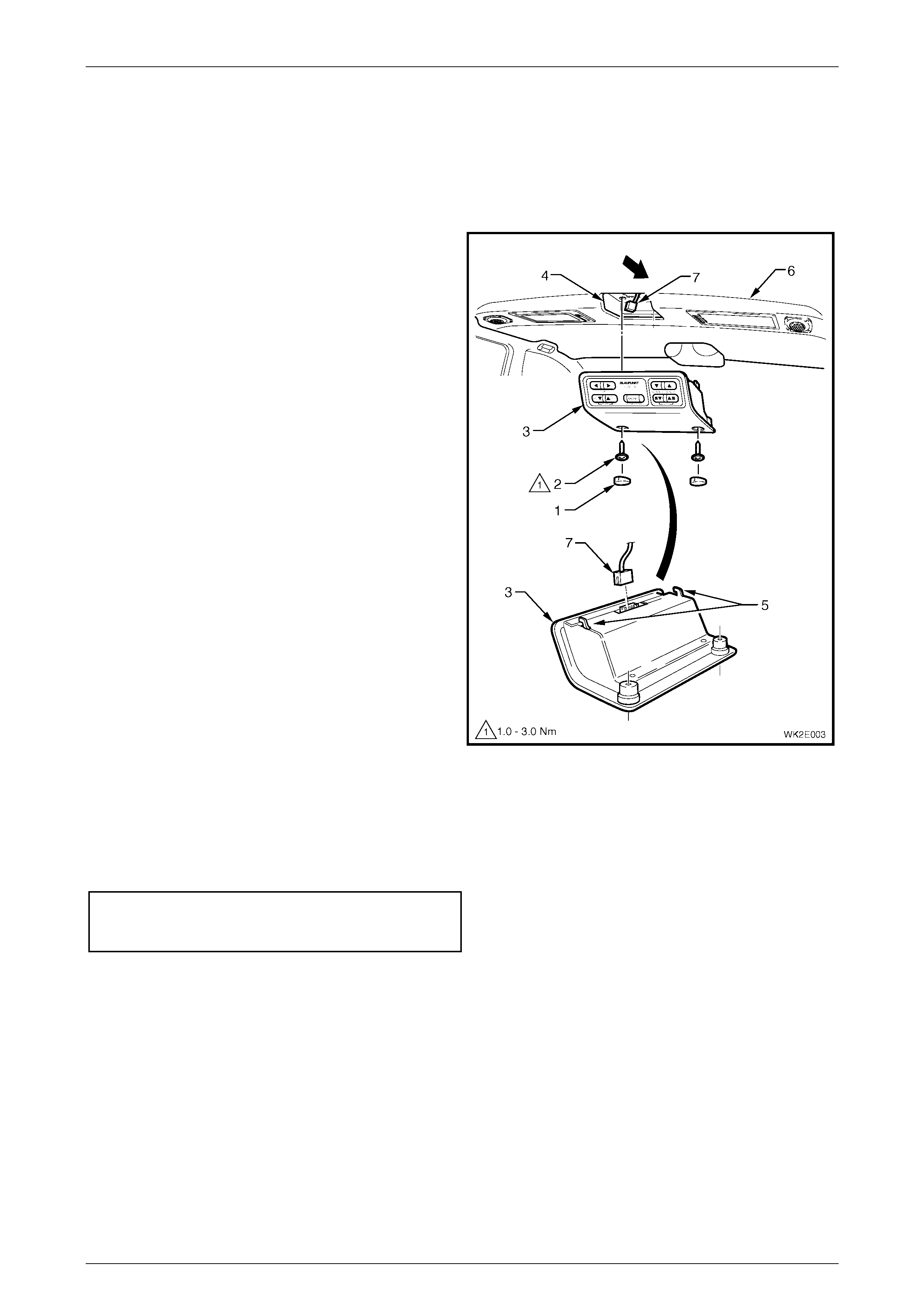
1 Remove blanking plugs (1) and screws (2) securing
the rear remote control assembly (3) to headlining
support (4).
2 Disengage the locating lugs (5) and lower rear remote
control assembly from the headlining (6).
3 Disconnect the wiring harness connector (7) from the
rear remote control assembly and remove the
assembly from the headlining.
Figure 2E – 4
Install
Installation of the rear remote control assembly is the reverse order of removal procedures, noting the following:
1 Tighten all screws to the specified torque.
Rear remote control
attaching screw torque
torque specific atio n ....................................1.0 – 3.0 Nm
NOTE
For bulb replacement procedures relating to the
rear remote control, refer to Section 12B,
3.4 REAR REMOTE CONTROL BULBS.

HVAC Occupant Climate Control (Auto A/C) – Removal and Installation Page 2E–9
20–MAR–2003 Page 2E–9
2.4 Centre Air Outlet Housing
LT Section – 08-175
Remove and Install
For removal and installation procedures applicable to the centre air outlet housing, refer to the disassembly procedures
in Section 1A3, 3.1 INSTRUMENT PANEL CENTRE TRIM ASSE MBLY.
HVAC Occupant Climate Control (Auto A/C) – Removal and Installation Page 2E–10
20–MAR–2003 Page 2E–10
2.5 Occupant Climate Control (Auto A/C)
HVAC unit
LT Section – 08-150
Remove and Install
To remove and install the Occupant Climate Control (Auto A/C) HVAC unit, refer to Section 2B, 3 HEATING,
VENTILATION AND AIR CONDITIONING (HVAC) UNIT in the MY2003 VY and V2 series Service Information, noting
that the following three procedures are specific to Level 2 to 5 MY2004 WK Series models:
• Instrument panel centre trim assembly removal and installation. Refer to Section 1A3, 3.1 INSTRUMENT PANEL
CENTRE TRIM ASSEMBLY.
• Windshield defroster grille removal and installation. Refer to Section 1A3, 3.2 W INDSHEILD DEFROSTER
GRILLE.
• Instrument panel compartment dampener removal and installation on RHD models. Refer to Section 1A3,
3.3 INSTRUMENT PANEL COMPARTMENT DAMPENER (Level 4 and 5 RHD only).
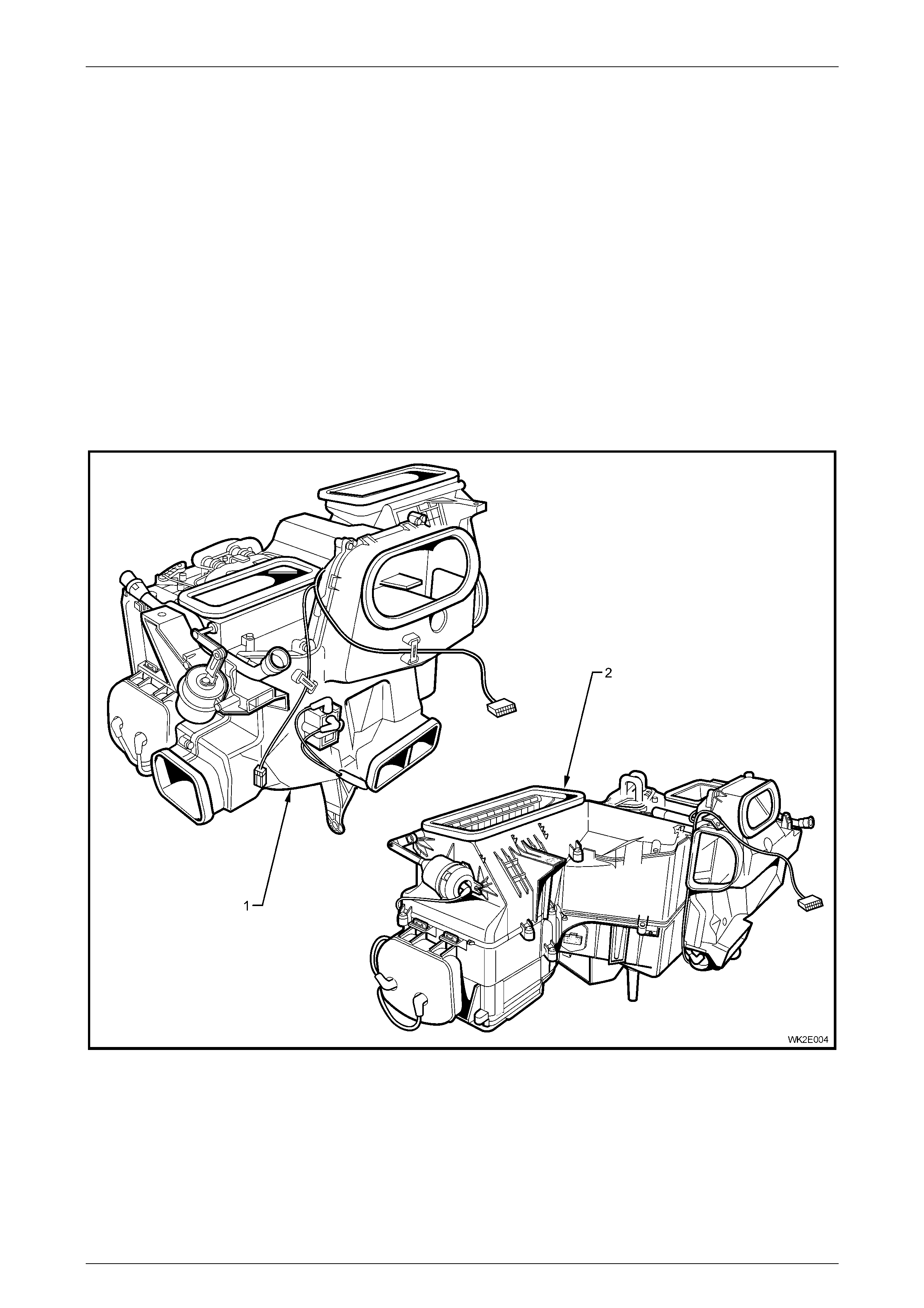
Figure 2E – 5
Legend
1 OCC (Auto A/C) HVAC unit – LHD 2 OCC (Auto A/C) HVAC unit – RHD

HVAC Occupant Climate Control (Auto A/C) – Removal and Installation Page 2E–11
20–MAR–2003 Page 2E–11
3 Torque Wrench Specifications
Occupant climate control module................................................... 1.0 – 3.0 Nm
Rear remote control.......................................................................1.0 – 3.0 Nm
HVAC Occupant Climate Control (Auto A/C) – Removal and Installation Page 2E–12
20–MAR–2003 Page 2E–12
4 Special Tools
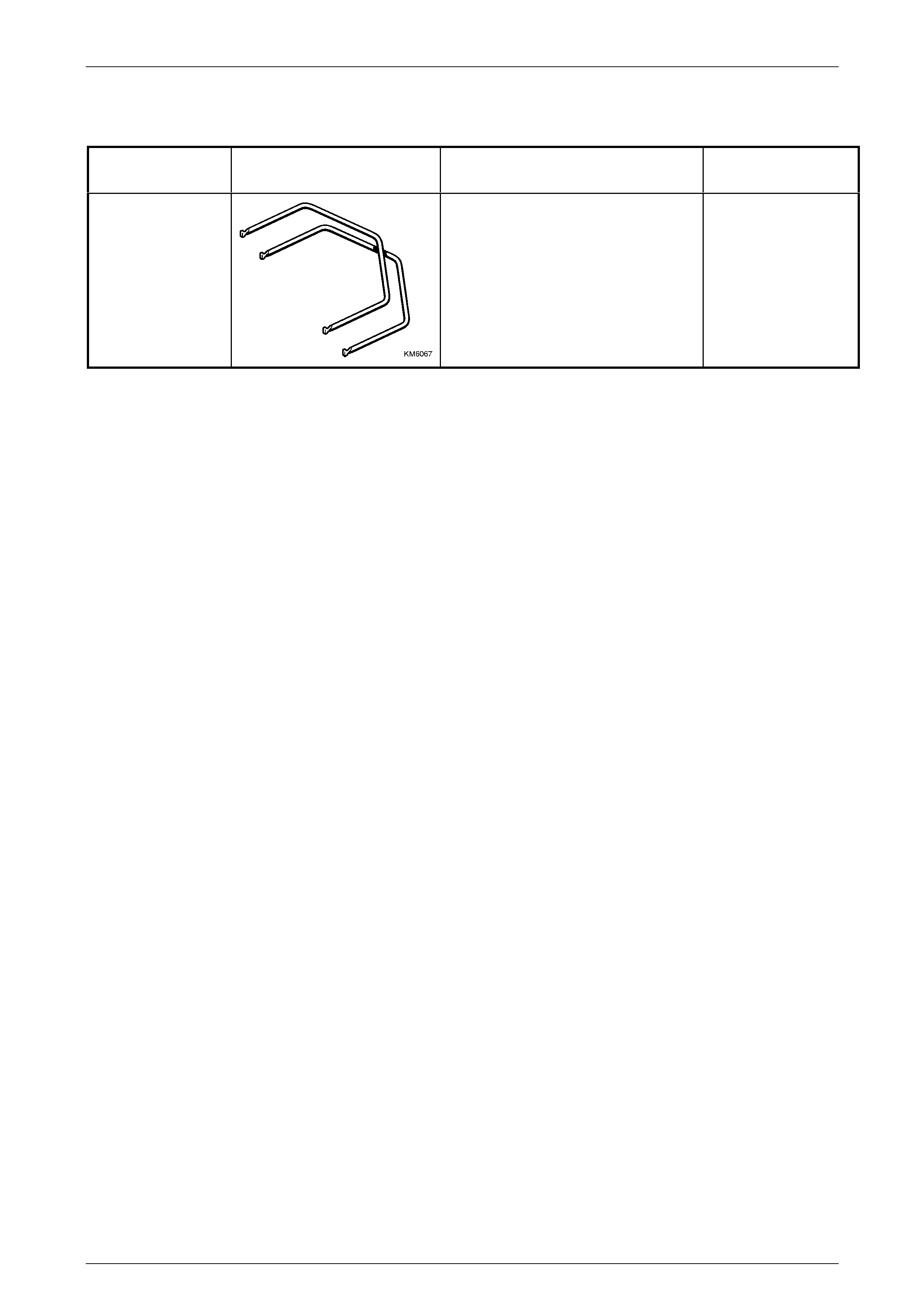
TOOL NUMBER ILLUSTRATION DESCRIPTION TOOL
CLASIFICATION
KM6067
RADIO REMOVAL TOOL
Used for removing VY and WK audio
head unit from its mounting location.
New tool for VY.
Mandatory