
Front Suspension Page 3–1
28-FEB-2003 Page 3–1
Section 3
Front Suspension
ATTENTION
Before performing any Service Operation or other procedure described in this Section, refer to Section 00
CAUTIONS AND NOTES for correct workshop practices with regard to safety and/or property damage.
1 General Information............................................................................................................................... 2
2 Wheel Alignment.................................................................................................................................... 3
3 Service Operations................................................................................................................................4
3.1 Service Notes and Cautions..................................................................................................................................4
4 Specifications......................................................................................................................................... 5
Front Suspension Details......................................................................................................................................5
Front Spring Details...............................................................................................................................................5
Front Stabilizer Bar Details....................................................................................................................................6
Front Strut Details..................................................................................................................................................6
Front Control Arm Details......................................................................................................................................7
Front Wheel Bearings............................................................................................................................................7
Suspension and Trim Height Specifications........................................................................................................7
Front Wheel Alignment Specifications.................................................................................................................9
Techline
Techline

Front Suspension Page 3–2
28-FEB-2003 Page 3–2
1 General Information
With the following exceptions, MY 2004 WK Series front suspension information carries over from MY 2003 VY Series
vehicles. For information not contained within this Section, refer to Section 3, Front Suspension in the MY 2003 VY and
V2 Series Service Information.
• The trim height, wheel alignment and general specifications are unique.
NOTE
There are three suspension options available for
MY 2004 WK Series Models; Standard
(Production Option FE1), Sports (Production
Option FE2) and Automatic Level Ride (FX3).
There are also numerous configurations for each
suspension option, depending on body type and
powertrain combination. For further information
regarding the identification of which suspension
option is fitted to a particular vehicle, refer to
Section 0A, 9.3 Body And Option Identification
Plate. For all other information regarding the
suspension application fitted to a particular
vehicle, refer to 4. Specifications in this Section.

Front Suspension Page 3–3
28-FEB-2003 Page 3–3
2 Wheel Alignment
With the following exceptions, MY 2004 WK Series front suspension wheel alignment information carries over from MY
2003 VY Series vehicles. For information not covered in this Section, refer to Sectio n 3, 2. Wheel Alignment in the MY
2003 VY Series and V2 Series Service Information.
• The wheel alignment specifications are unique, refer to 4. Specifications in this Section.
NOTE
Even though some of the front wheel alignment
angles are not normally measurable and (in some
instances) not adjustable, each is an inherent
part of the vehicle's dynamic suspension tuning
that has been developed over an extended
testing program.

Front Suspension Page 3–4
28-FEB-2003 Page 3–4
3 Service Operations
With the following exceptions, MY 2004 WK Series front suspension service operation information carries over from MY
2003 VY Series vehicles. For information not covered in this Section, refer to Sectio n 3, 3. Service Operatio ns in the MY
2003 VY Series and V2 Series Service Information.
• The trim height specifications are unique, refer to 4. Specifications in this Section.
3.1 Service Notes and Cautions
NOTE
Whenever a road wheel and/or brake disc is
removed from or installed to a MY 2004 WK
Series vehicle, it MUST be done in accordance
with the procedure provided in Section 10,
2.3 Wheel Removal And Reinstallation in the MY
2003 VY Series and V2 Series Service
Information.
CAUTION
Whenever any component that forms part of
the ABS (if fitted) is disturbed during Service
Operations, it is vital that the complete ABS
system be checked, using the procedure as
detailed in Section 5B, 4.4 ABS & TCS
Function Check (V6 engines) or 5.4 ABS &
TCS Function Check (GEN III V8 engines) in
the MY 2003 VY Series and V2 Series Service
Information.
Front Suspension Page 3–5
28-FEB-2003 Page 3–5
4 Specifications
Front Suspension Details
SUSPENSION
CONFIGURATION COMPRESSION - 2/3 COMPRESSION
OF BUMPER (mm) REBOUND (mm)
LEVEL 1 to 4 & FE1 81 114
FE2 67 127
FX3 81 114
RHD LEVEL 5 & FE1 75 122
LHD LEVEL 5 & FE1 81 114
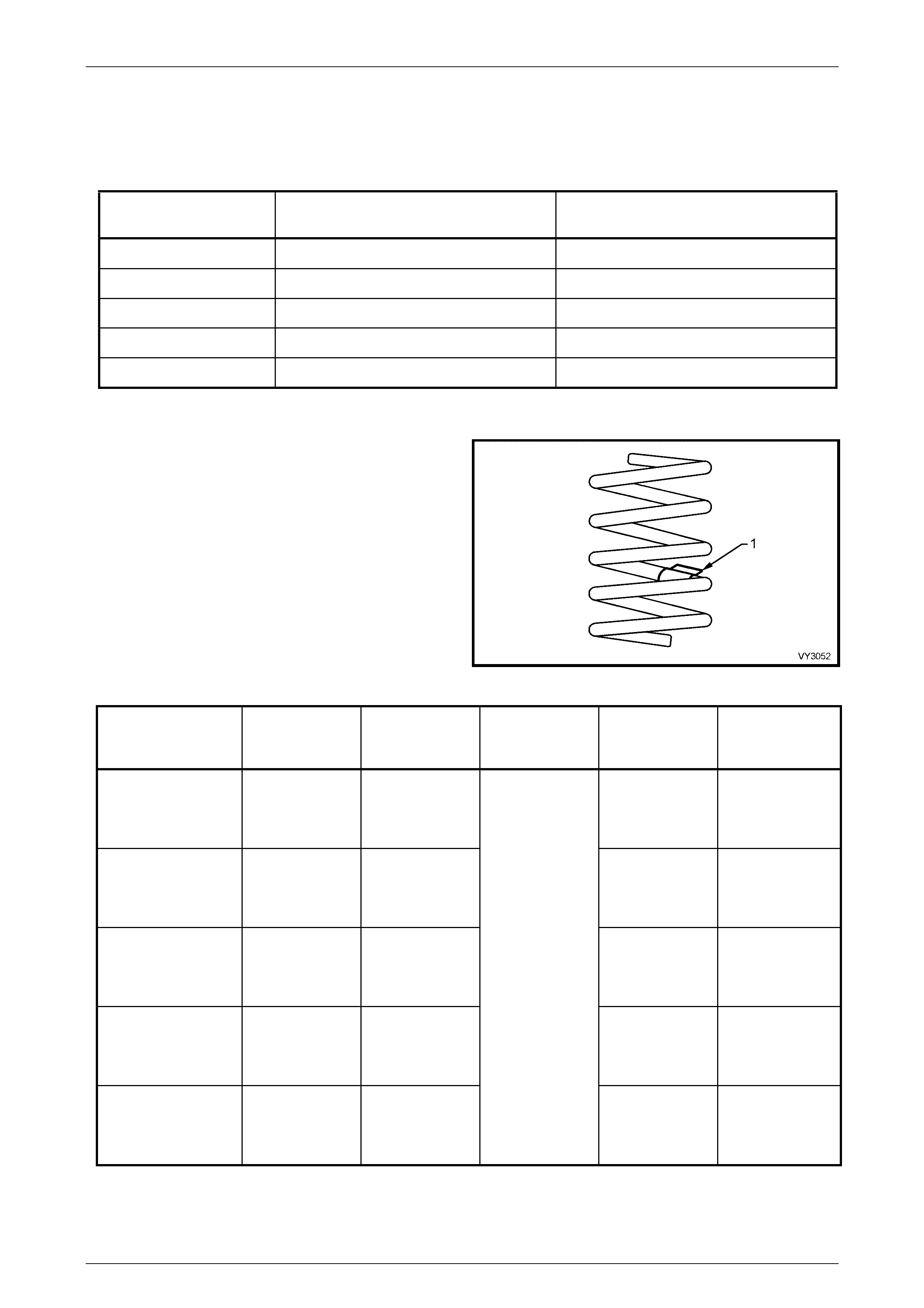
Front Spring Details
Identification of the front spring fitted to a particular vehicle
can be achieved by cross-referencing the two digit code
provided on the production identification tag (1) with the
table below.
Figure 3-1
SUSPENSION
CONFIGURATION NUMBER OF
COILS FREE LENGTH
(mm) INSIDE
DIAMETER
(mm)
SPRING TYPE
AND RATE PRODUCTION
ID CODE
RHD & FE1 5.74 363 VARIABLE
37 - 35 N/mm
(3600 ± 110 N
@ 218 mm)
JN
LHD & FE1 6.05 444
VARIABLE
19 - 23 N/mm
(3700 ± 110 N
@ 210 mm)
HN
FE2 6.11 355
136 ±1.5 VARIABLE
24 - 31 N/mm
(3660 ± 110 N
@ 210 mm)
ED
RHD & FX3 5.74 363 VARIABLE
37 - 35 N/mm
(3600 ± 110 N
@ 218 mm)
JN
LHD & FX3 6.05 444
VARIABLE
19 - 23 N/mm
(3700 ± 110 N
@ 210 mm)
HN
Front Suspension Page 3–6
28-FEB-2003 Page 3–6
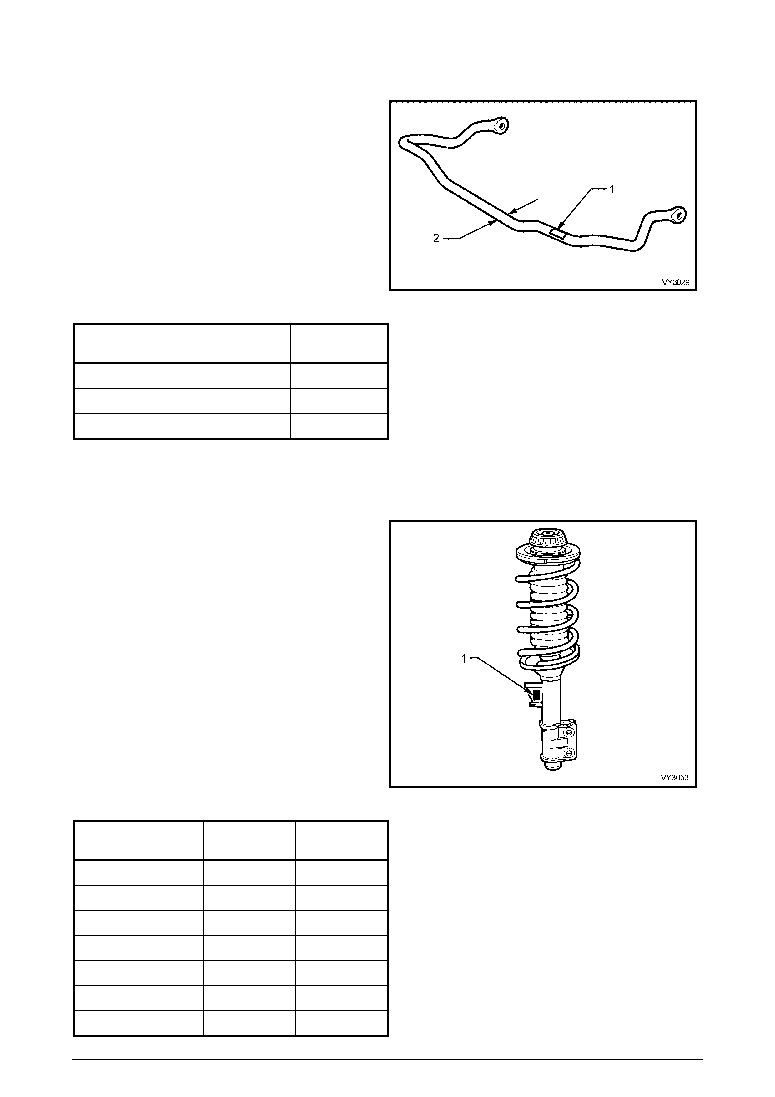
Front Stabilizer Bar Details
Identification of the front stabilizer bar fitted to a particular
vehicle can be achieved by cross-referencing the two digit
code provided on the production identification tag (1) with
the table below.
The table also provides stabilizer bar diameters (2).
Figure 3-2
SUSPENSION
CONFIGURATION DIAMETER
(mm) PRODUCTION
ID CODE
RHD LEVEL 4 27 YB
RHD LEVEL 5 26 YA
LHD 26 YA
Front Strut Details
Type...............................................................................................Wet strut - non-serviceable
Piston Diameter............................................................................................................. 30 mm
Identification of the front strut assemblies fitted to a
particular vehicle can be achieved by cross-referencing the
two digit code provided on the production identification tag
(1) with the table below.
Figure 3-3
SUSPENSION
CONFIGURATION RIGHT-HAND
ID CODE LEFT-HAND
ID CODE
RHD LEVEL 4 & FE1 NV NW
RHD LEVEL 5 & FE1 MC MD
LHD & FE1 MC MD
FE2 ZP ZX
RHD LEVEL 4 & FX3 NV NW
RHD LEVEL 5 & FX3 MC MD
LHD & FX3 MC MD
Front Suspension Page 3–7
28-FEB-2003 Page 3–7
Front Control Arm Details
Forged with rubber bushes for attachment to the front crossmember and tens ion rod. Ball joint is a press fit
into the control arm and is not serviced separately.
Front Wheel Bearings
Type....................................................................................................Double row ball bearing
Lubricant...................................................................................Sealed for life: non-adjustable
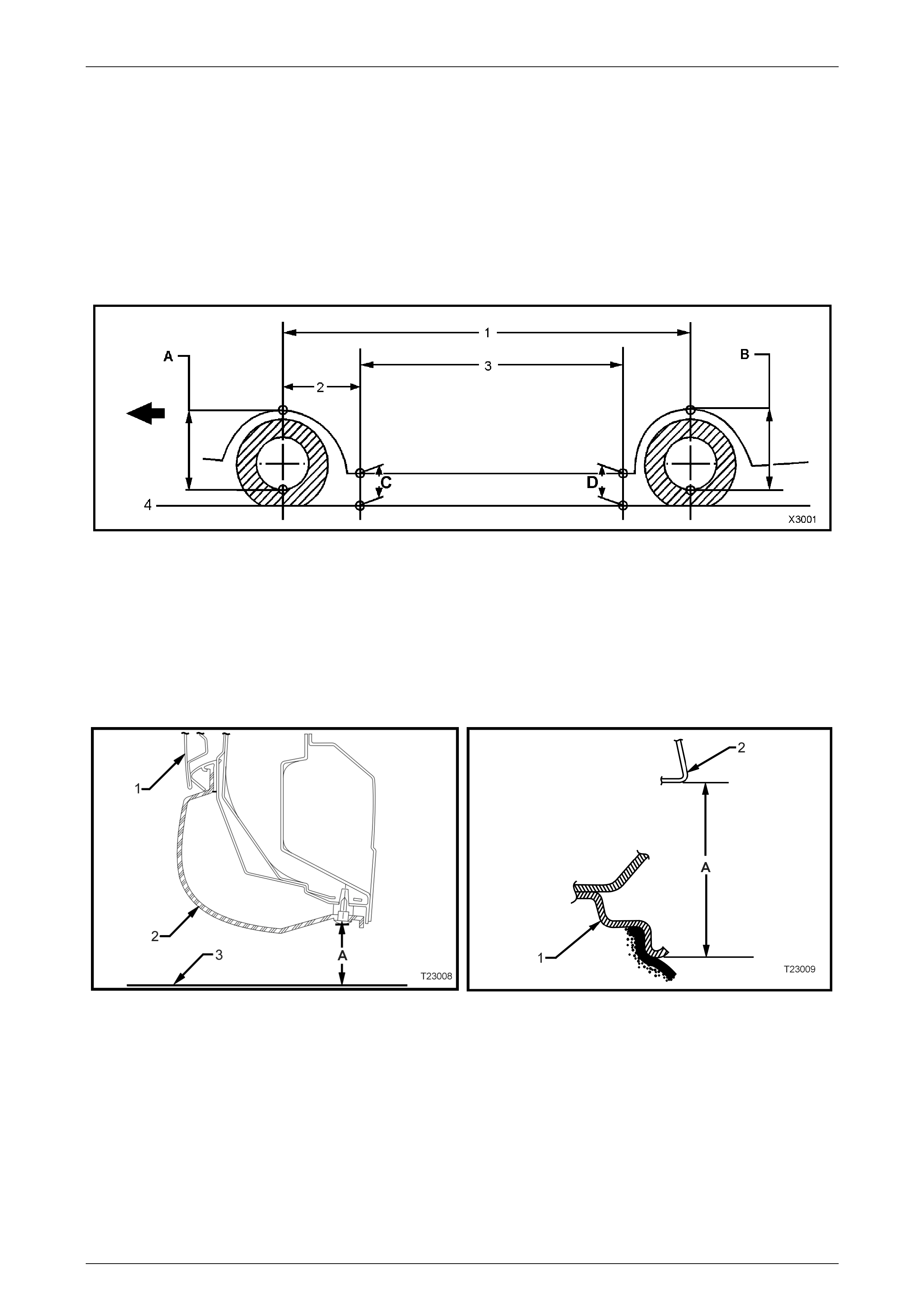
Suspension and Trim Height Specifications
Figure 3-4
Legend
A Front Suspension Height Location
B Rear Suspension Height Location
C Front Trim Height Check Location
D Rear Trim Height Check Locati on
1 Wheelbase: All Models - 2938 mm
2 Reference Point: All Models - 584.5 mm
3 Trim Height Spacing: All Models - 1765 mm
4 Ground Line
Figure 3-5 - Rear Trim Height Checking Location
(Front Similar) Figure 3-6 - Front and Rear Suspension Height
Checking Location
Legend Legend
1 Door
2 Trim
3 Ground Line
A Trim Height
1 Wheel Rim
2 Fender Opening
A Suspension Height
Front Suspension Page 3–8
28-FEB-2003 Page 3–8
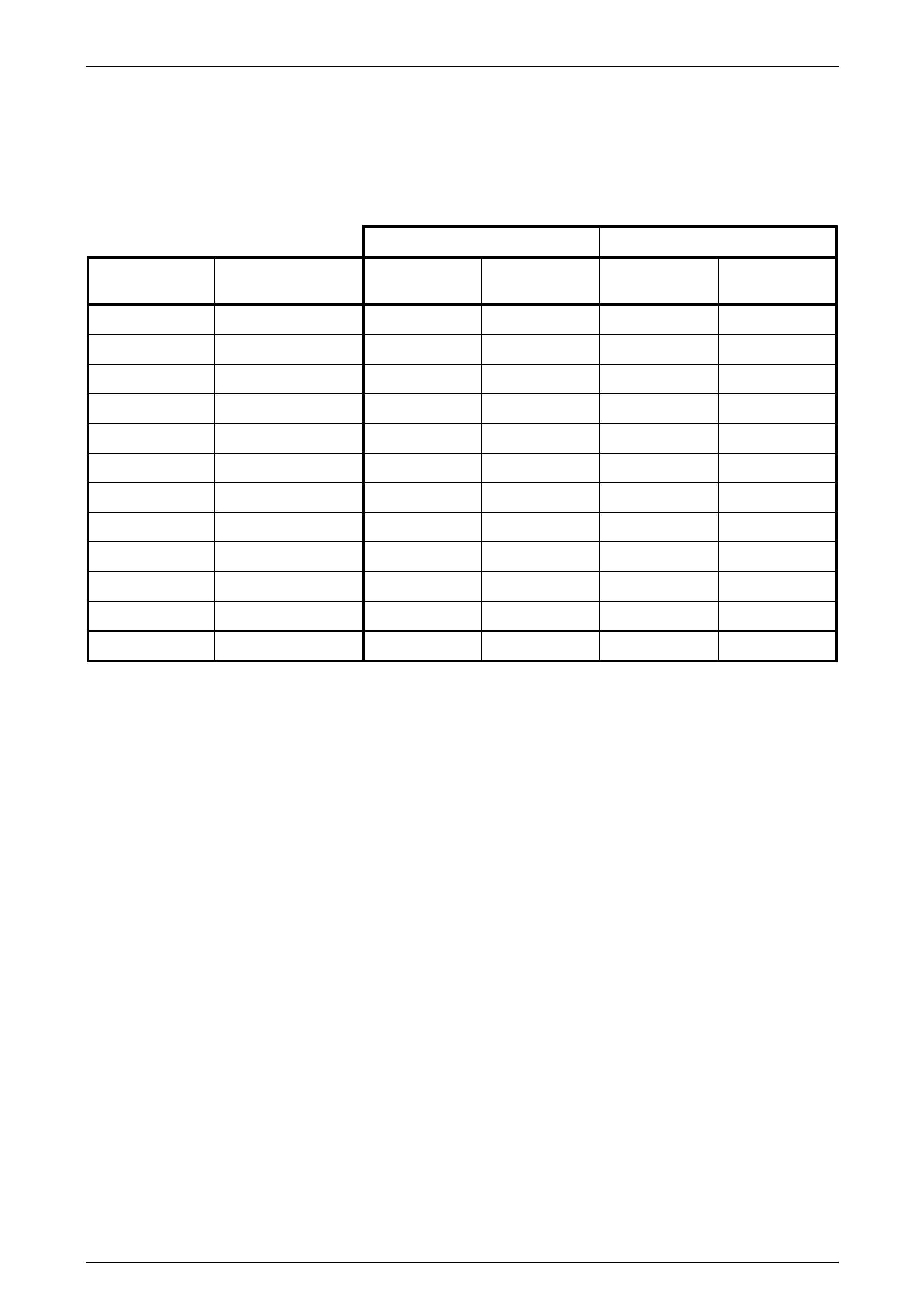
NOTE
The following suspension/trim height dimensions
are for reference only and are only intended to be
a guide. Refer to Section 3, 3.2 Suspension and
Trim Height, Check in the MY 2003 VY and V2
Series Service Information for ride height
variations and additional procedures.
MY 2004 WK MODELS SUSPENSION HEIGHT (mm) TRIM HEIGHT (mm)
VEHICLE
DESCRIPTION SUSPENSION
CONFIGURATION FRONT
('A' in Fig. 3-54) REAR
('B' in Fig. 3-54) FRONT
('C' in Fig. 3-54) REAR
('D in Fig. 3-54)
Level 1 FE1 594 588 190 201
Level 1 FE2 586 580 176 186
Level 1 FX3 594 588 190 201
Level 2 FE1 606 600 190 201
Level 2 FE2 599 593 176 186
Level 2 FX3 606 600 190 201
Level 3 FE2 611 605 176 186
Level 4 FE1 606 600 190 201
Level 4 FX3 606 600 190 201
RHD Level 5 FE1 613 606 185 192
LHD Level 5 FE1 606 600 190 201
Level 5 FX3 618 612 190 201
Front Suspension Page 3–9
28-FEB-2003 Page 3–9
Front Wheel Alignment Specifications
FRONT WHEEL ALIGNMENT AT KERB WEIGHT
Wheel Alignment Angle Specifications - All Models
Camber -0° 12' ± 0° 18'
Caster 7° 45' ± 1° 15'
Toe-in Degrees Total 0° 10' ± 0° 10'
Degrees per Wheel 0° 5' ± 0° 5'
Toe-out on Turns 1° 42' @ 20 ° turn angle ± 1° 30'
Steering Axis Inclination Angle 12° 52' ± 1° 30'
Included Angle 12° 40' ± 1° 30'
SERVICE INFORMATION
The adjusting values for camber, caster and toe-in must remain within the tolerances specified. The difference
between left and right must not exceed the following:
CASTER 0° 36'
CAMBER 0° 48'
TOE-IN 0° 10'
The specifications listed are the nominal value, with acceptable variance from this central point. Where possible, an
attempt should always be made to achieve the nominal settings when changing.
Front wheel camber alters as a function of front suspension height.
Camber adjusting bolt: After loosening both lower strut to steering knuckle bolts and nuts, adjust camber by turning
the adjusting bolt clockwise to decrease negative camber and anti-clockwise to increase negative camber. After
adjustment, both bolts and nuts MUST be replaced with new parts and tightened to the recommended torque setting.
The rear wheel alignment should be checked and corrected if necessary (refer to Section 4A, Rear Suspension)
before checking front wheel alignment.
Fuel Mass with Full Tank - All Models 56 kg