
Rear Suspension Page 4A-1
Page 4A–1
Section 4A
Rear Suspension
ATTENTION
Before performing any Service Operation or other procedure described in this Section, refer to Section 00
CAUTIONS AND NOTES for correct workshop practices with regard to safety and/or property damage.
1 General Information............................................................................................................................... 3
1.1 General Description...............................................................................................................................................3
Automatic Level Ride Suspension........................................................................................................................3
2 Principles of Operation ......................................................................................................................... 5
2.1 Automatic Level Ride Suspension........................................................................................................................5
Activation................................................................................................................................................................5
Loaded Vehicle.......................................................................................................................................................6
Unloaded Vehicle ...................................................................................................................................................6
Deactivation............................................................................................................................................................6
Reset Procedure.....................................................................................................................................................6
3 Service Operations - Automatic Level Ride Suspension .................................................................. 7
3.1 Service Notes and Cautions..................................................................................................................................7
3.2 Initial Air Charge.....................................................................................................................................................8
3.3 Air Leak Test...........................................................................................................................................................9
3.4 Relieving System Air Pressure ...........................................................................................................................10
3.5 Compressor Assembly ........................................................................................................................................11
Remove .................................................................................................................................................................11
Disassemble .........................................................................................................................................................12
Reassemble ..........................................................................................................................................................12
Reinstall ................................................................................................................................................................13
3.6 Air Lines................................................................................................................................................................14
Remove .................................................................................................................................................................14
Reinstall ................................................................................................................................................................15
3.7 Level Ride Shock Absorber.................................................................................................................................1 6
Remove .................................................................................................................................................................16
Reinstall ................................................................................................................................................................17
3.8 Ride Height Sensor..............................................................................................................................................18
Remove .................................................................................................................................................................18
Reinstall ................................................................................................................................................................19
4 Service Maintenance Operations - Automatic Level Ride Suspension ......................................... 20
Air Lines................................................................................................................................................................20
Wiring Harness.....................................................................................................................................................20
Air Filter.................................................................................................................................................................20
5 Diagnosis - Automatic Level Ride Suspension ................................................................................ 21
Equipment.............................................................................................................................................................21
Ride Height Sensor Reset....................................................................................................................................21
5.1 Preliminary Diagnostic Procedure......................................................................................................................21
5.2 Compressor Assembly Test - Motor...................................................................................................................22
5.3 Compressor Assembly Test - Solenoid..............................................................................................................23
5.4 Ride Height Sensor Test - Compressor..............................................................................................................24

Rear Suspension Page 4A-2
Page 4A–2
5.5 Ride Height Sensor Test - Solenoid....................................................................................................................25
5.6 Wiring Diagram - Automatic Level Ride Suspension........................................................................................26
5.7 Wiring Harness Layout - Automatic Level Ride Suspension............................................................................27
6 Specifications....................................................................................................................................... 28
Front Suspension Details....................................................................................................................................28
Rear Suspension Service Alignment Data.........................................................................................................28
Rear Spring Details..............................................................................................................................................28
Rear Shock Absorber Details..............................................................................................................................29
Rear Stabilizer Bar Details...................................................................................................................................30
7 Torque Wrench Specifications........................................................................................................... 31
8 Special Tools........................................................................................................................................ 32

Rear Suspension Page 4A-3
Page 4A–3
1 General Information
Independent rear suspension (IRS) is fitted as standard equipment on all MY 2004 WK Series Models, and is equipped
with variable rate minibloc coil rear springs and direct ac ting shock absorbers.
The rear suspension is contained within a rear crossmember assembly, which is attached by hydraulic rubber bushes at
each front corner to the vehicle underbody. Rear location is provided by a rear mounting block bolted to the differential
carrier assembly that is in turn, attached to the crossmember.
Two trailing arms are attached to the crossmember pivot points through rubber bushes. The trailing arms provide
attachment of the additional control arms, the rear brake components, trunnion assemblies, flanges and drive shaft outer
(rear wheel) bearings.
A decoupled type stabiliser bar is attached to the top of the crossmember by two brackets and insulating bushes. The
outer ends of the stabiliser bar are attached to each trailing arm by a link via insulating bushes.
The standard (Production Option FE1) suspension application utilises twin tube hydraulic shock absorbers that are
double acting and are mounted between the vehicle underbody and each trailing arm. The sports suspension (Production
Option FE2) application, utilises twin tube, gas pressurised shock absorbers. The level ride suspension (Production
Option FX3) application utilises the pneumatically adjustable (Superlift) type rear shock absorbers which are also
available as an accessory or as part of a 2100 kg tow bar package for select MY 2004 WK Series Models.
Numerous variable rate minibloc rear springs are fitted to MY 2004 WK Series Models, depending on the suspension
option fitted to the vehicle. The rear springs have insulating pads top and bottom, and are maintained in the correct
location by mounts on the vehicle underbody and the trailing arms.
As part of the KL7 production LPG option, MY 2004 WK Series are fitted an up-rated spring package to compensate for
the extra weight of the LPG tank.
To identify vehicles that are fitted with the KL7 LPG option, a Holden By Design (HBD) identification plate is attached to
the upper front panel, refer to Section 8A2, 1.2 Identification Plates and Warning Labels in the MY 2003 VY and V2
Series Service Information.
An additional control arm is also fitted as standard equipment to all MY 2004 WK Series Vehicles. The inner ends of the
addition control arms contain rubber bushes and are attached to brackets welded to the rear crossmember. The outer
end of the additional control arm is secured to the trailing arm by a ball joint. The purpose of the additional control arm is
to maintain the rear wheel camber and toe angles during suspension travel, whilst also providing a means of adjusting
the rear wheel toe.
The IRS as fitted to MY 2004 WK Series vehicles carries over from MY 2003 VY Series vehicles, noting the following:
• Automatic level ride (Production Option FX3) is available as an option on all WK Series vehicles.
• Sports suspension (Production Option FE2) is not available on MY 2004 WK Series Level 5 vehicles.
For information relating to the rear suspension as fitted to MY 2004 WK Series vehicles not covered in this Section, refer
to Section 4A, Rear Suspension in the MY 2003 VY and V2 Series Service Information
NOTE
For further information regarding how to identify
which suspension application (Production Option)
is fitted to a particular vehicle, refer to Section 0A,
9.3 Body and Option Identification Plate.
1.1 General Description
Automat i c Level Ride Suspension
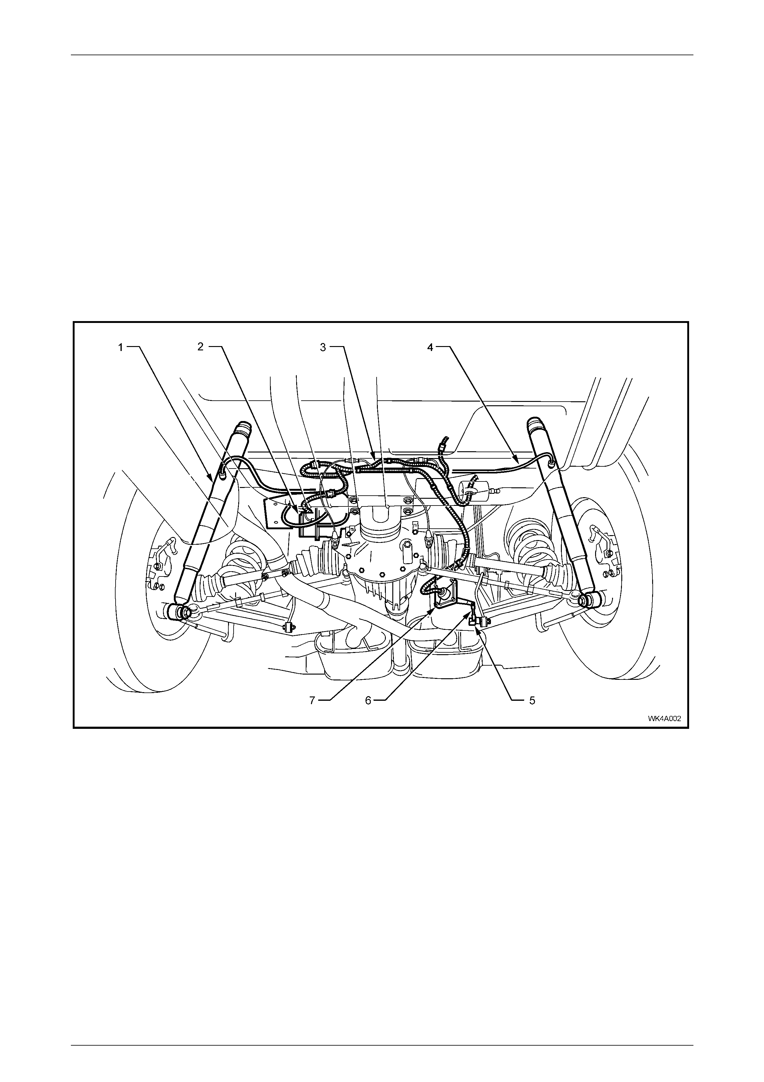
Automatic level ride is an electronically controlled system that main tains the vehicle at a constant trim height, regardless
of vehicle load. This feature uses a specifically designed electronic ride height sensor (5), fixed to the rear crossmember
on the right-hand side. This sensor controls an electric motor driving a single cylinder air compressor (2) and an exhaust
solenoid valve. The compressor (2) supplies the necessary pressure to operate the Superlift shock absorbers (1) via
snap-on air lines (4). The Superlift shock absorbers assist the rear springs in supporting the vehicle body under all loads.
The ride height sensor (5) has an integrated electronic controller that is programmed to adjust the ride height only when
necessary, ignoring sudden changes, as experienced on bum py roads. The design of the system maintains trim at all
times when the ignition is on. As a safeguard to prevent the battery discharging, an electronic timer switches off the
compressor if it runs for a prolonged period (ie. due to an air leak in the system).
Rear Suspension Page 4A-4
Page 4A–4
The compressor assembly includes a maximum pressure release valve and an air drier. All air entering or exhausting the
system flows through the drier, which has an internal minimum retention valve preventing the airbag, surrounding each
shock absorber, from completely exhausting, independent of the sensor controlled exhaust valve.
Electric power to operate the system is supplied by an integrated wiring harness (3).
There are two main benefits resulting from the automatic level ride feature:
• Headlamp aim and rear view mirror adjustment being maintained independent of load.
• Rear tyre camber and toe-in are held to their optimum alignment to minimise tyre wear.
NOTE
If air pressure is lost from the system while the
vehicle is in service (eg. an air leak), the Superlift
shock absorber airbag will most likely be
damaged, requiring replacement.
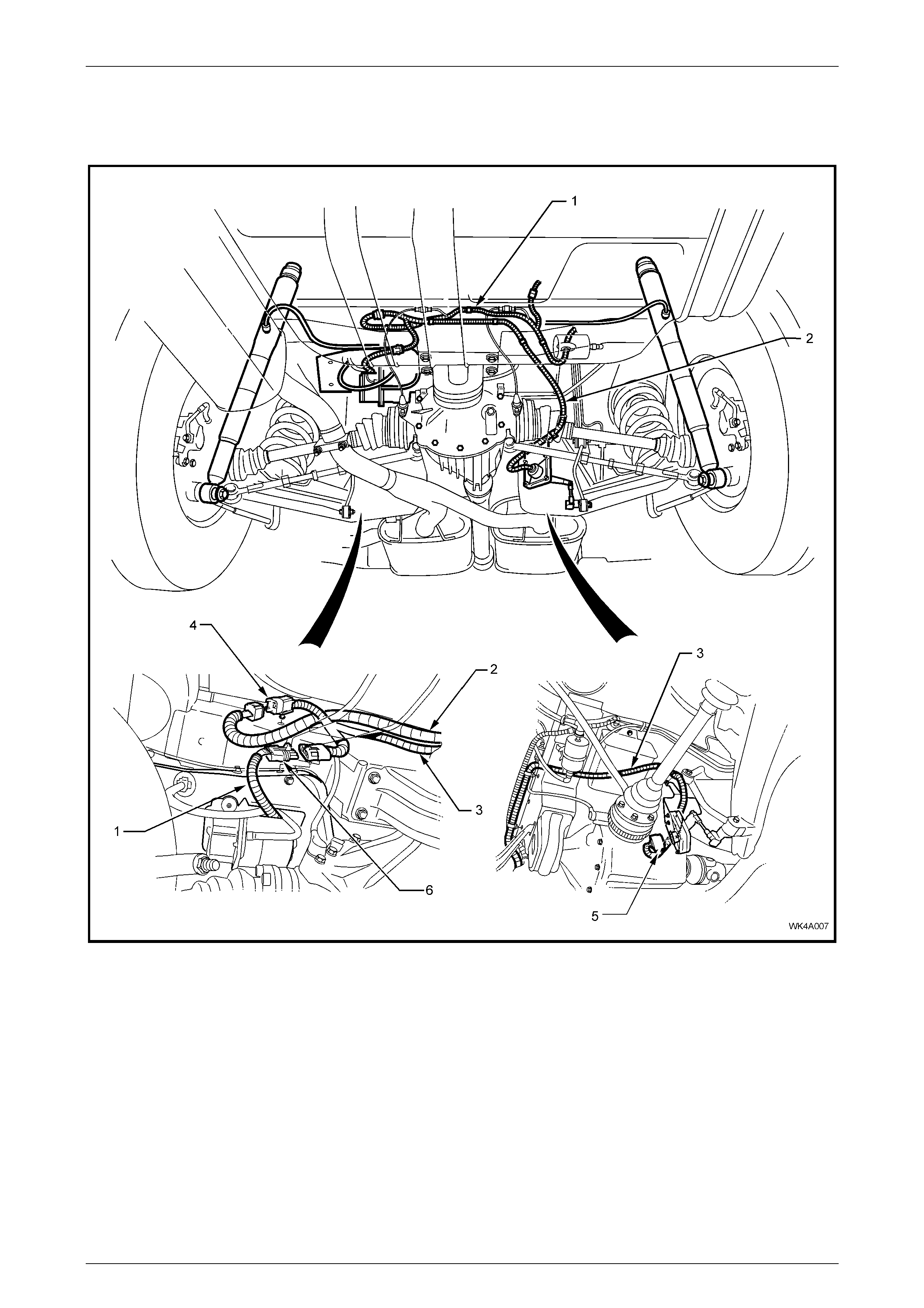
Figure 4A-1
Legend
1 Superlift Shock Absorbers
2 Air Compressor Assembly
3 Level Ride Wiring Harness
4 Air Lines
5 Ride Height Sensor Ball Stud Plate
6 Ride Height Sensor Connect i ng Link
7 Ride Height Sensor
Rear Suspension Page 4A-5
Page 4A–5
2 Principles of Operation
2.1 Automatic Level Ride Suspension
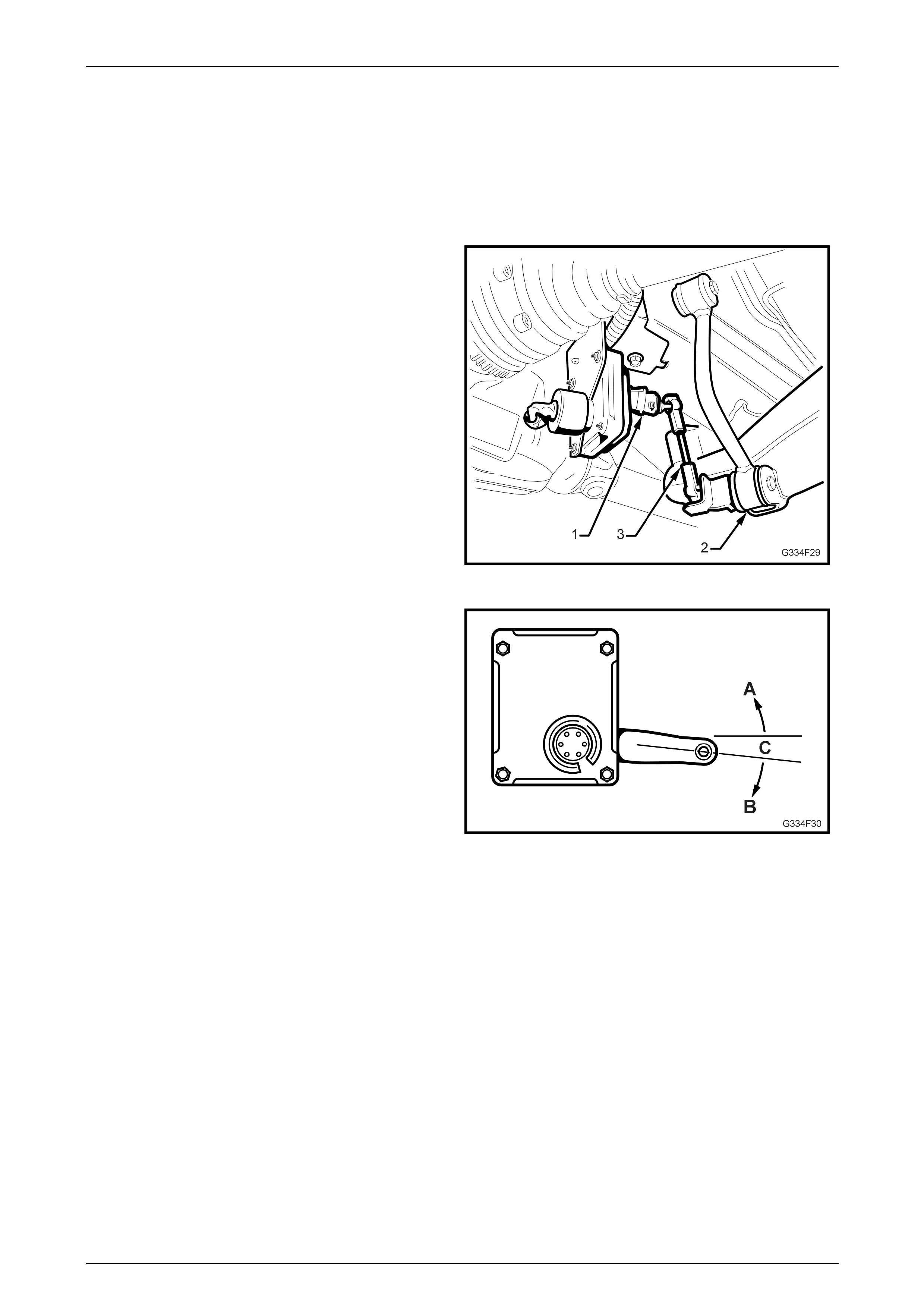
Activation
The sensor's actuating arm (1) is attached to the lower
control arm (2) via a connecting link (3).
Figure 4A-2
Before any activation can occur, the actuating arm must
remain in either the intake (A) or exhaust zone (B) for a
approximately 20 seconds. This time delay prevents the
compressor or exhaust valve from activating when the
vehicle encounters sudden bumps.
Another stability feature is a 'deadband' zone (C), which
helps to minimise hunting, by deactivating the compressor
and solenoid when the vehicle trim goes into or onto the
deadband zone or one of its edges.
Figure 4A-3
Rear Suspension Page 4A-6
Page 4A–6
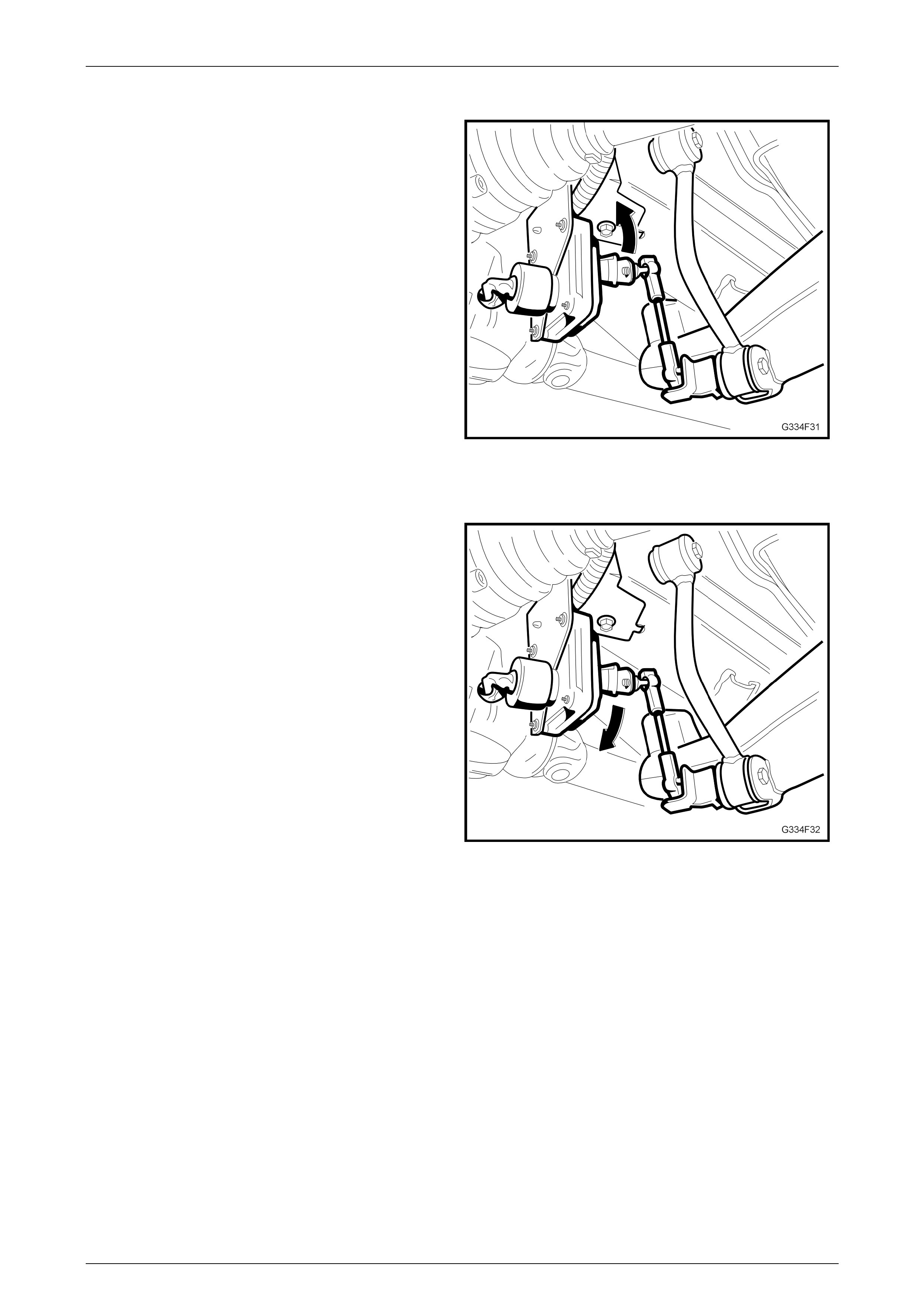
Loaded Vehicle
When the vehicle is loaded, the vehicle body moves
downward into the intake zone, causing the actuating arm
to move upwards (arrow).
After approximately 20 seconds in this position, the sensor
relieves the compressor head pressure by briefly activating
the compressor relay. The compressor starts and
pressurises the Superlift shock absorbers until the vehicle
body aligns with the bottom edge of the deadband, at which
point the compressor stops.
Figure 4A-4
Unloaded Vehicle
When the vehicle is unloaded, the vehicle body moves
upward into the exhaust zone, causing the actuating arm to
move downwards.
After approximately 20 seconds in this position, the sensor
activates the exhaust relay. The exhaust solenoid activates
and vents pres sure from the Superlift shock absorbers until
the vehicle body aligns with the top edge of the deadband,
at which point the solenoid deactivates.
Figure 4A-5
Deactivation
The compressor and exhaust solenoid operations are monitored and controlled by individual but interconnected timers.
The timers deactivate specific trimming operations under the following conditions:
• If the compressor runs for a cumulative time of more than four and a half minutes, the compressor timer
deactivates all system operations.
• If the exhaust solenoid is active for a cumulative time of more than four and a half minutes, the solenoid timer
deactivates the solenoid.
No further operation of thes e components can take place until the timers are reset.
Reset Procedure
The procedure to reset the timers is:
1 Turn the ignition ON.
2 Turn the ignition OFF for one minute.
3 Turn the ignition ON, once more to complete the operation.
Rear Suspension Page 4A-7
Page 4A–7
3 Service Operations - Automatic
Level Ride Suspension
ATTENTION
All rear suspension fasteners are important attaching parts as they affect the performance of vital
components and/or could result in major repair expense. Where specified in this section, fasteners MUST be
replaced with parts of the same part number or a GM approved equivalent. Do not use fasteners of an inferior
quality or substitute design.
Torque values must be used as specified during reassembly to ensure proper retention of all rear suspension
components.
Through out this section, fastener torque wrench specifications may be accompanied with the following
identification marks:
!
!!
! Fasteners must be replaced after loosening.
"
""
" Vehicle must be at curb height before final tightening.
#
##
# Fasteners either have micro encapsulated sealant applied or incorporate a mechanical thread lock and
should only be re-used once. If in doubt, replacem ent is recommended.
If one of these identification marks is present alongside a fastener torque wrench specification, the
recommendation regarding that fastener must be adhered to.
3.1 Service Notes and Cautions
CAUTION
Whenever any component that forms part of
the ABS (if fitted) is disturbed during Service
Operations, it is vital that the complete ABS
system be checked, using the procedure as
detailed in Section 5B, 4.4 ABS & TCS
Function Check (V6 engines) or 5.4 ABS &
TCS Function Check (GEN III V8 engines), in
the MY 2003 VY and V2 Series Service
Information.
NOTE
Whenever a road wheel and/or brake disc is
removed from or installed to a MY 2004 WK
Series vehicle, it MUST be done in accordance
with the procedure provided in Section 10,
2.3 Wheel Removal and Reinstallation in the
MY 2003 VY and V2 Series Service Inform ation.
NOTE
To ensure proper retention of the multi-link
control arm, the ball joint stud and the
corresponding tapered hole in the semi-trailing
arm must be cleaned of dirt and foreign matter
prior to reinstallation.
Rear Suspension Page 4A-8
Page 4A–8
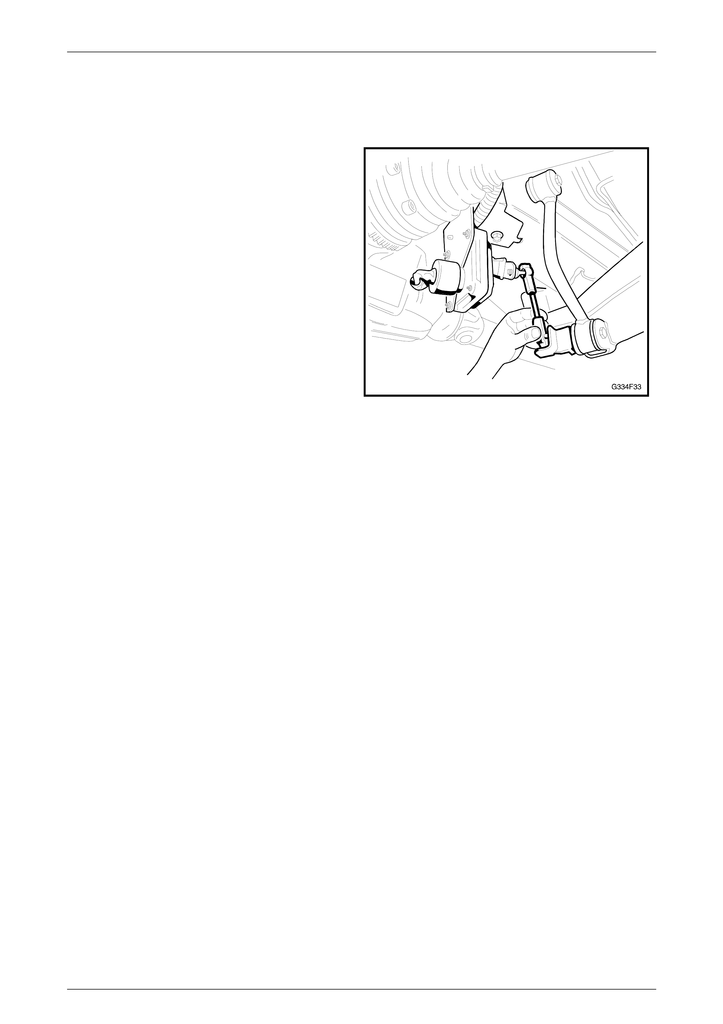
3.2 Initial Air Charge
LT Section No. - 06-212
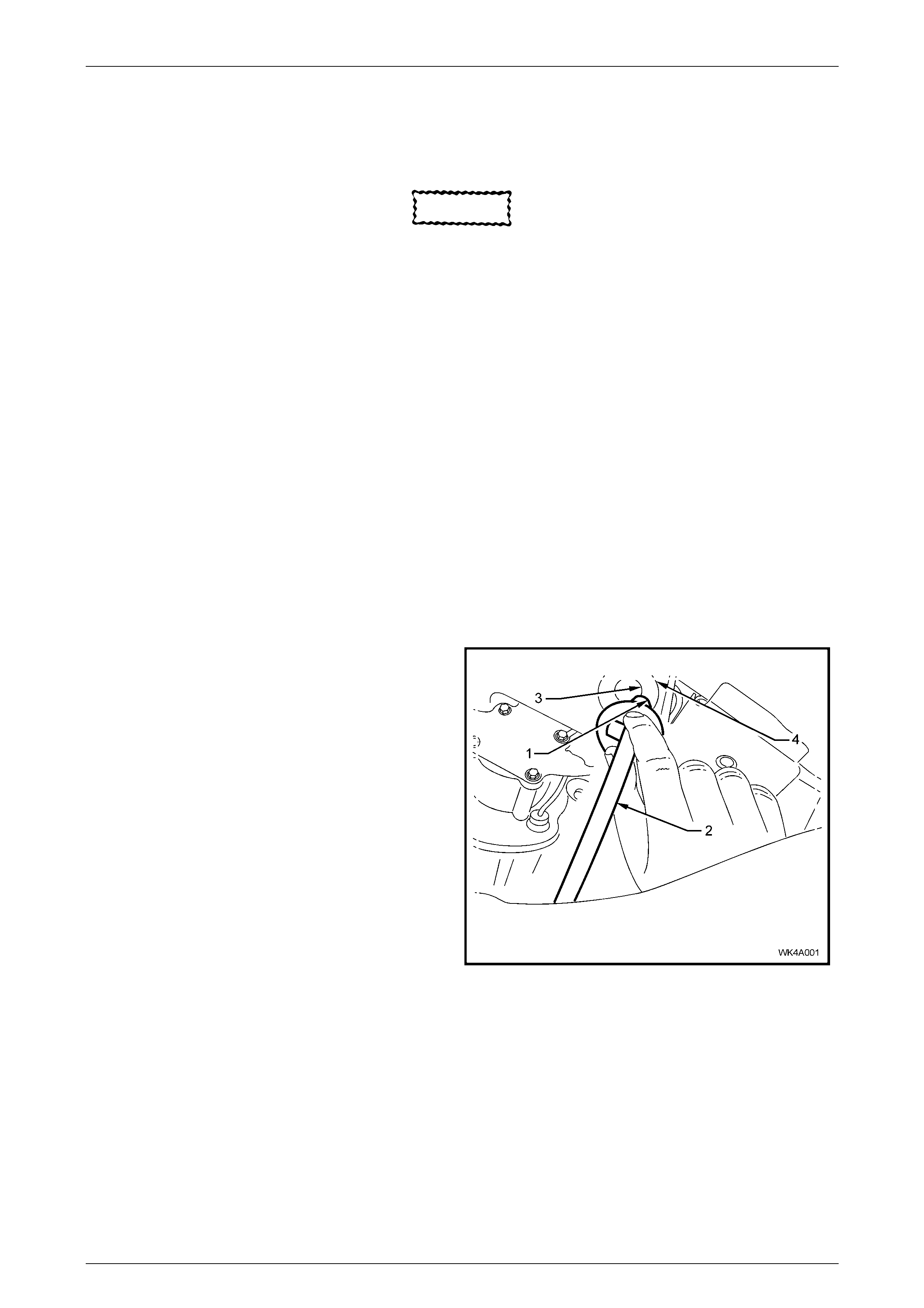
1 Turn the ignition on.
2 Disconnect the lower end of the sensor connecting
link.
3 Push the sensor arm upward, above the horizontal
plane for approximately 20 seconds, until the
compressor is act iv ated.
4 Leave the compressor running for approximately 30
seconds to inflate the sup erlift shock absorbers.
5 Turn the ignition off.
6 Check the system for leaks.
7 Reconnect the sensor connecting link.
Figure 4A-6
Rear Suspension Page 4A-9
Page 4A–9
3.3 Air Leak Test
LT Section No. - 06-212
CAUTION
If air pressure in the level ride system is
lost during service procedures, do not lower
the vehicle until system pressure has
been restored, as damage will most likely
result. Charge the system as detailed in
3.2 Initial Air Charge in this Section.
1 Ensure the system is pressurised. Refer to 3.2 Initial Air Charge in this Section if required.
2 Starting at the shock absorber connections, apply a
foaming leak check solution (commercially available,
or a soap solution mixed with water) to all fittings and
connections.
3 Carefully inspect the fittings and connections for the
presence of air bubbles in the solution.
4 Repair any detected leaks as required.
5 Retest the system for air leaks .
6 If air still leaks from the system, isolate sections of the
system until the source of the leak is found.
7 Clean off the residual solution.
Figure 4A-7
Rear Suspension Page 4A-10
Page 4A–10
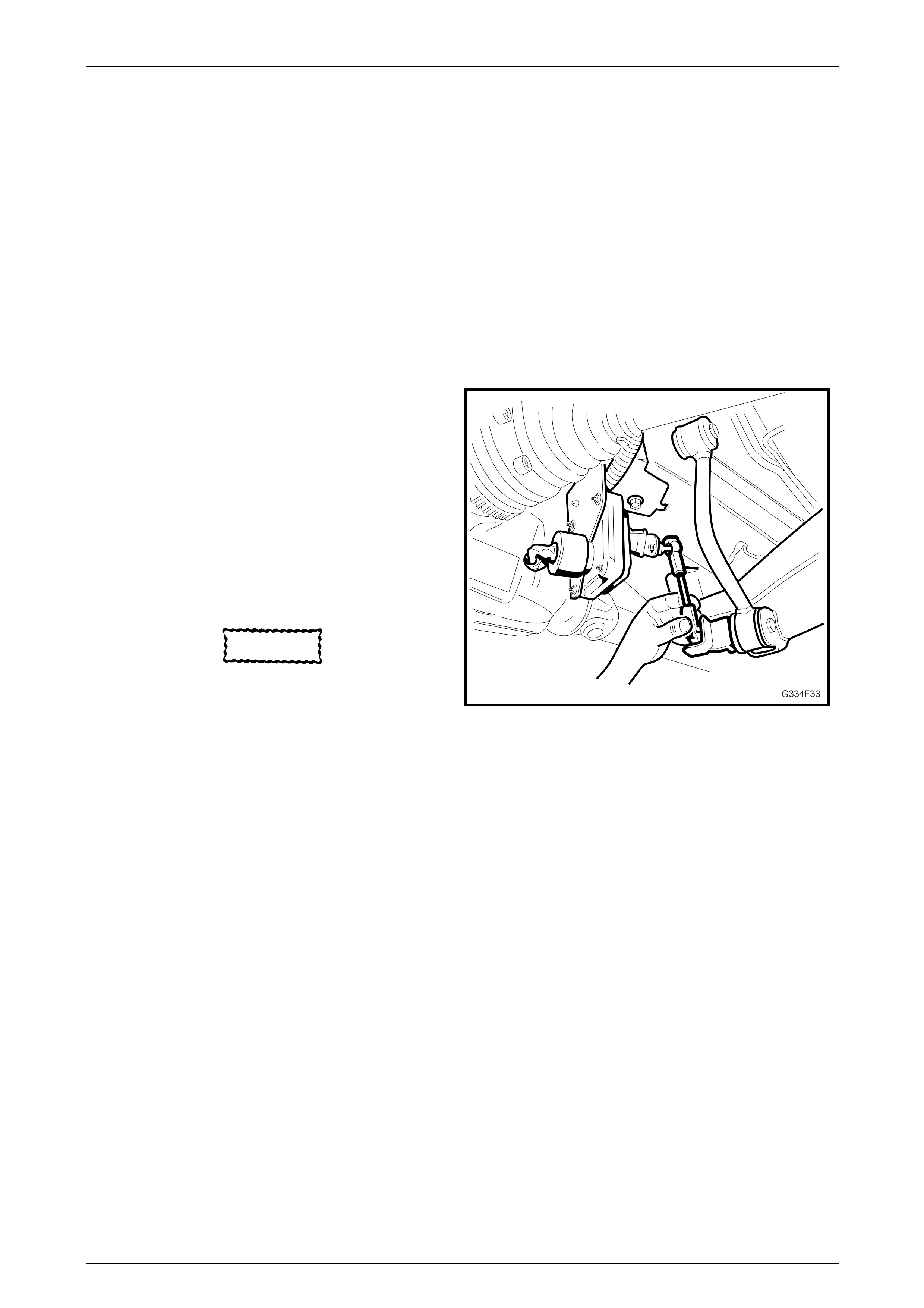
3.4 Relieving System Air Pressure
LT Section No. - 06-212
NOTE
If air pressure in the level ride system is lost
during service procedures, do not lower the
vehicle until system pressure has been restored,
as damage will most likely result. Charge the
system as detailed in 3.2 Initial Air Charge in this
Section
Prior to carrying out service operations on the level ride suspension system, where the air pressure in the system needs
to be released, the following procedure must be followed:
1 With the rear of the vehicle raised and supported on
safety stands under the trailing arms, turn the ignition
on.
2 Disconnect the lower end of the sensor connecting
link.
3 Pull the sensor arm downward, below the horizontal
plane and hold until the exhaust solenoid is activated.
4 Maintain the sensor lever position, allow the exhaust
solenoid to remain active for approximately 30
seconds to relieve the system air pressure or until no
sound of exhausting air remains.
CAUTION
Do not leave the sensor lever in the
lowered position for more than four and a
half minutes (with the ignition on),
otherwise the solenoid timer will
deactivate the solenoid and the timer
must then be reset.
Figure 4A-8
5 Turn the ignition off.
6 Proceed with service operations as required.
NOTE
After service work has been completed, the
system pressure must be reinstated before
lowering the vehicle. Refer to 3.2 Initial Air
Charge in this Section for the procedure.
Rear Suspension Page 4A-11
Page 4A–11
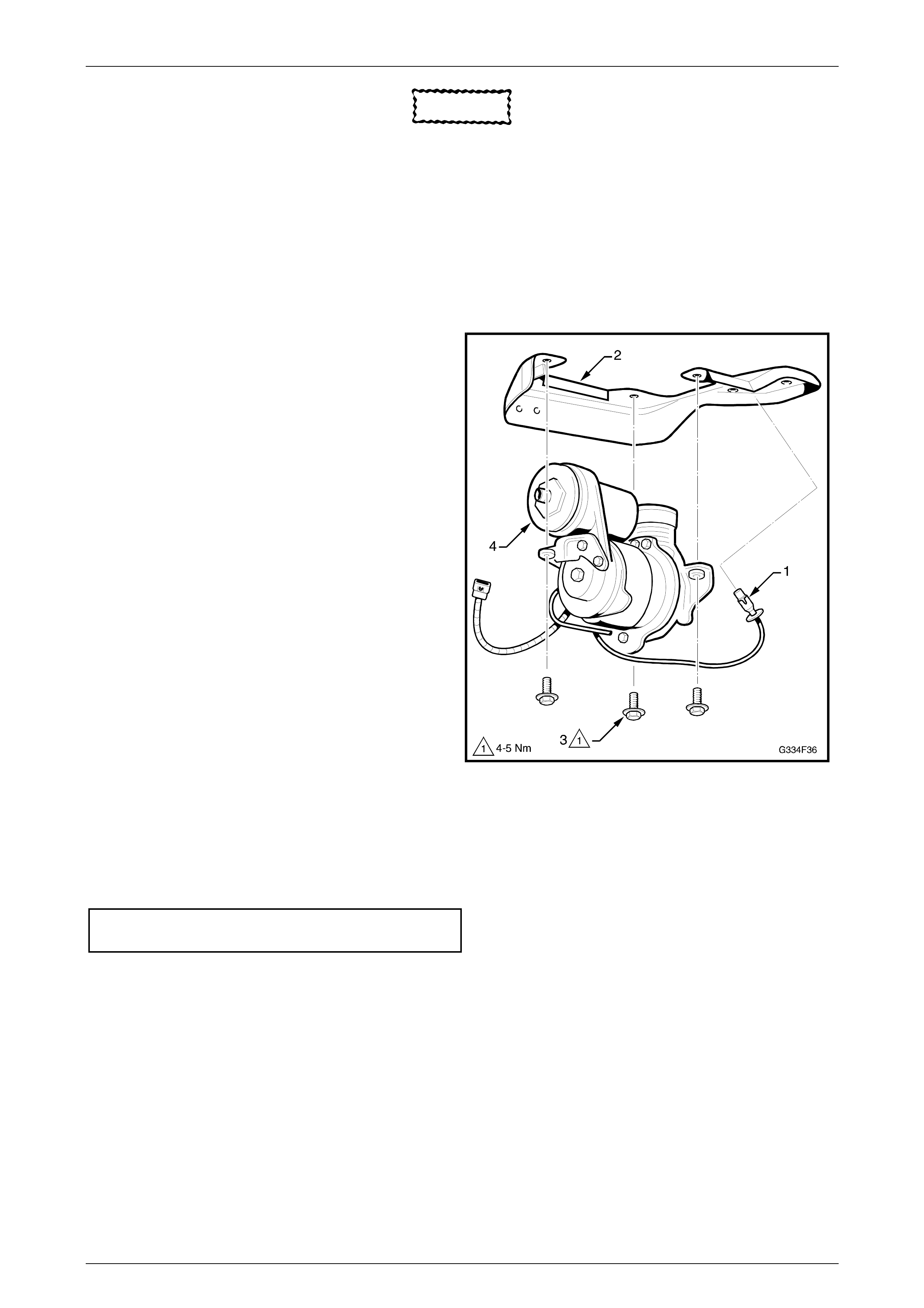
3.5 Compressor Assembly
LT Section No. - 06-212
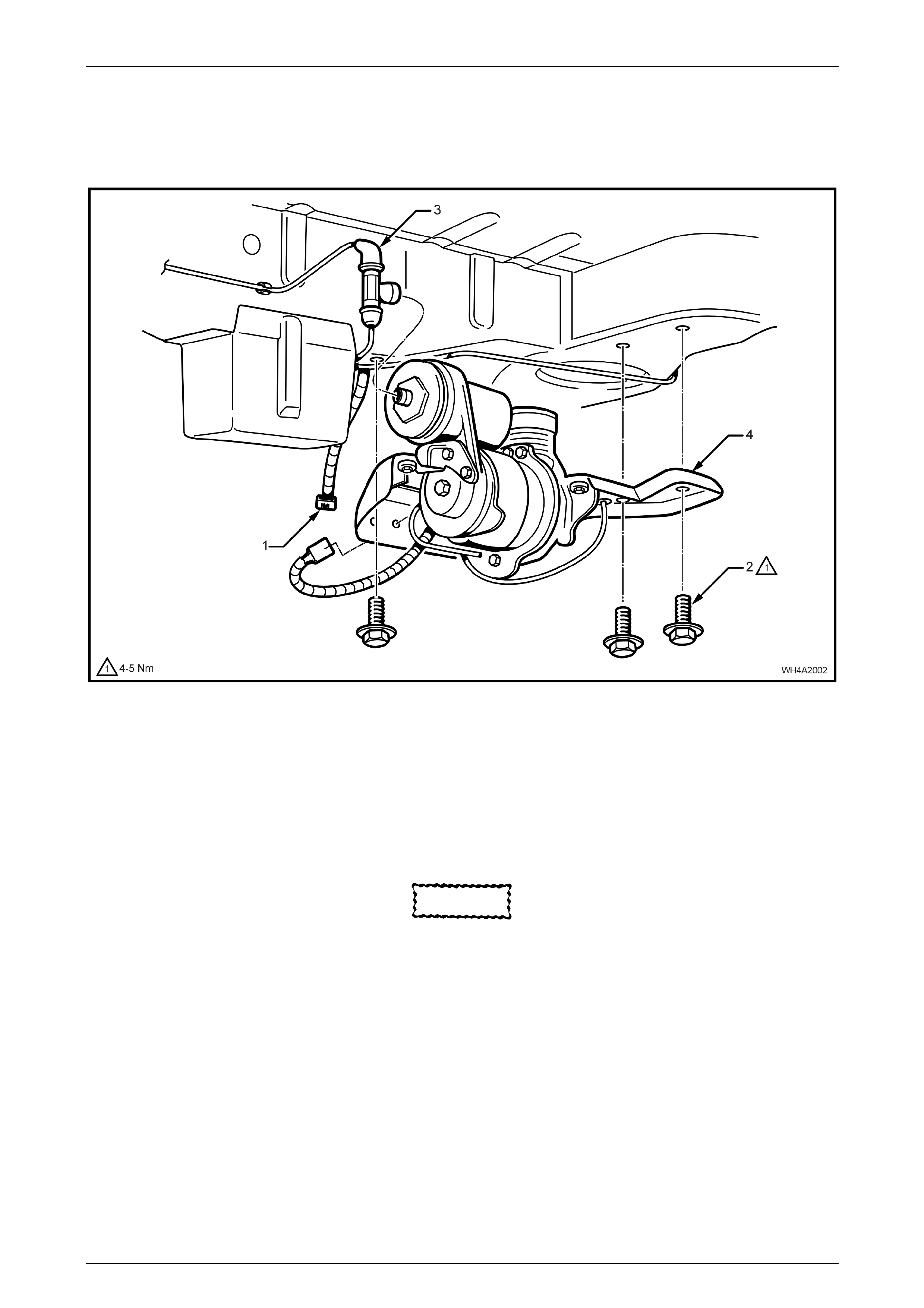
Figure 4A-9
Legend
1 Level Ride Compress or Wi ri ng Harness Connector
2 Level Ride Compress or Bracket to Underbody Mounting
Bolts, 3 Places.
3 Airline to Compressor T-piece
4 Level Ride Compress or Mount i ng Brack et
Remove
CAUTION
If air pressure in the level ride system is
lost during service procedures, do not lower
the vehicle until system pressure has
been restored, as damage will most likely
result. Charge the system as detailed in
3.2 Initial Air Charge in this Section.
1 Disconnect the battery, negative lead first.
2 Raise the vehicle.
3 Relieve system air pressure. Refer to 3.4 Relieving System Air Pressure, in this Section.
4 Unclip the level ride wiring harness (1) from the compressor assembly mounting bracket (4) and disconnect the
wiring connector, refer to Figure 4A-19.
5 Remove the three bolts (2) attaching the compressor assembly mounting bracket (4) to the vehicle body.
Rear Suspension Page 4A-12
Page 4A–12
CAUTION
Support the compressor assembly. Do not
allow it to drop.
6 Disconnect the airline T-connector (3) from the compressor by rotating the T-piece 90 degrees, then carefully
pulling it away from the compressor.
7 Lower the compressor assembly.
Disassemble
1 Remove the filter (1) from the mounting bracket (2).
2 Remove the three bolts (3) attaching the compressor
(4) to the mounting bracket.
3 Test that the filter is clean and free from restrictions
by removing the filter from the tube and blowing
through it from the hose connection end. If any
restriction is felt, replace the filter.
Figure 4A-10
Reassemble
1 Install the components in the reverse order to disassembly.
2 Tighten the bolts to the specified torque.
Compressor mounting attaching bolt
torque specification ..........................................4 – 5 Nm
Rear Suspension Page 4A-13
Page 4A–13
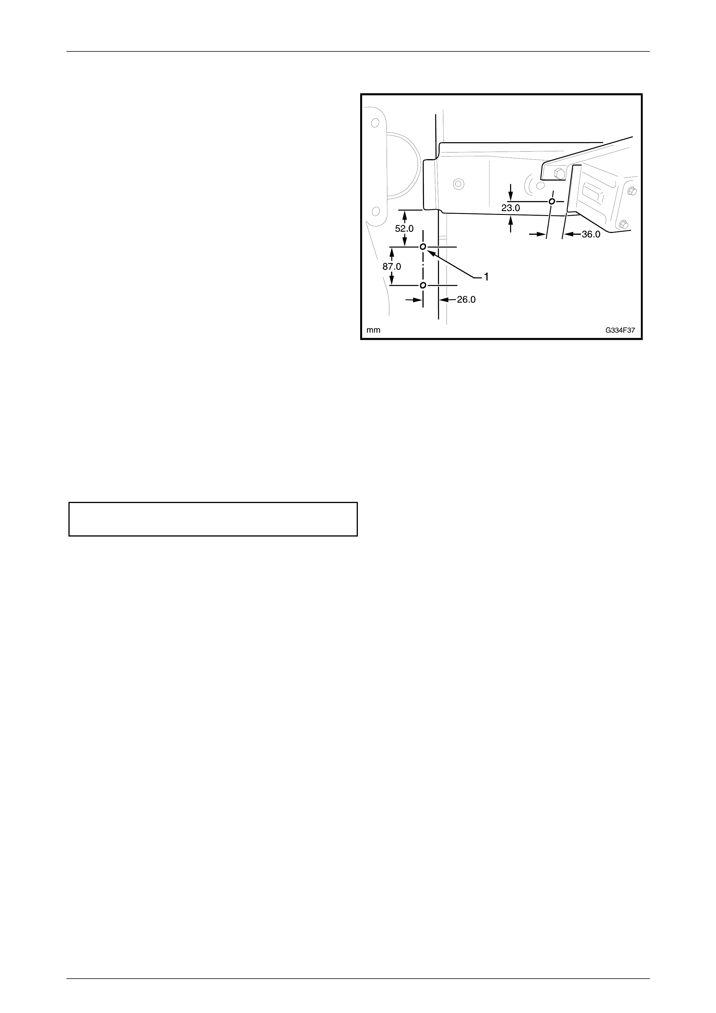
Reinstall
1 If the left-hand rear longitudinal and/or crossmember
has been replaced, compressor assembly mounting
holes (1) will have to be drilled as required.
Figure 4A-11
2 Bring the compressor assembly up to the air line and connect the T-piece.
NOTE
Ensure that the airline is correctly routed, placed
in al l of its mounting clips and does no t foul with,
or rub against any components or body fittings.
3 Install the three moun ting bolts and tighten to the specified torque.
Compressor assembly mounting attaching
bolt torque specification .................................... 4 – 5 Nm
4 Connect the wiring harness connector and clip the harness into position.
NOTE
Ensure that the harness is correctly routed,
placed in all of its mounting clips/ties and does
not foul with, or rub against any components or
body fittings.
5 Connect the battery.
NOTE
Do not completely lower the vehicle until the
system air pressure has been reinstated.
6 Charge the system with air and check the system for leaks, as described in 3.2 Initial Air Charge and
3.3 Air Leak Test in this Section.
Rear Suspension Page 4A-14
Page 4A–14
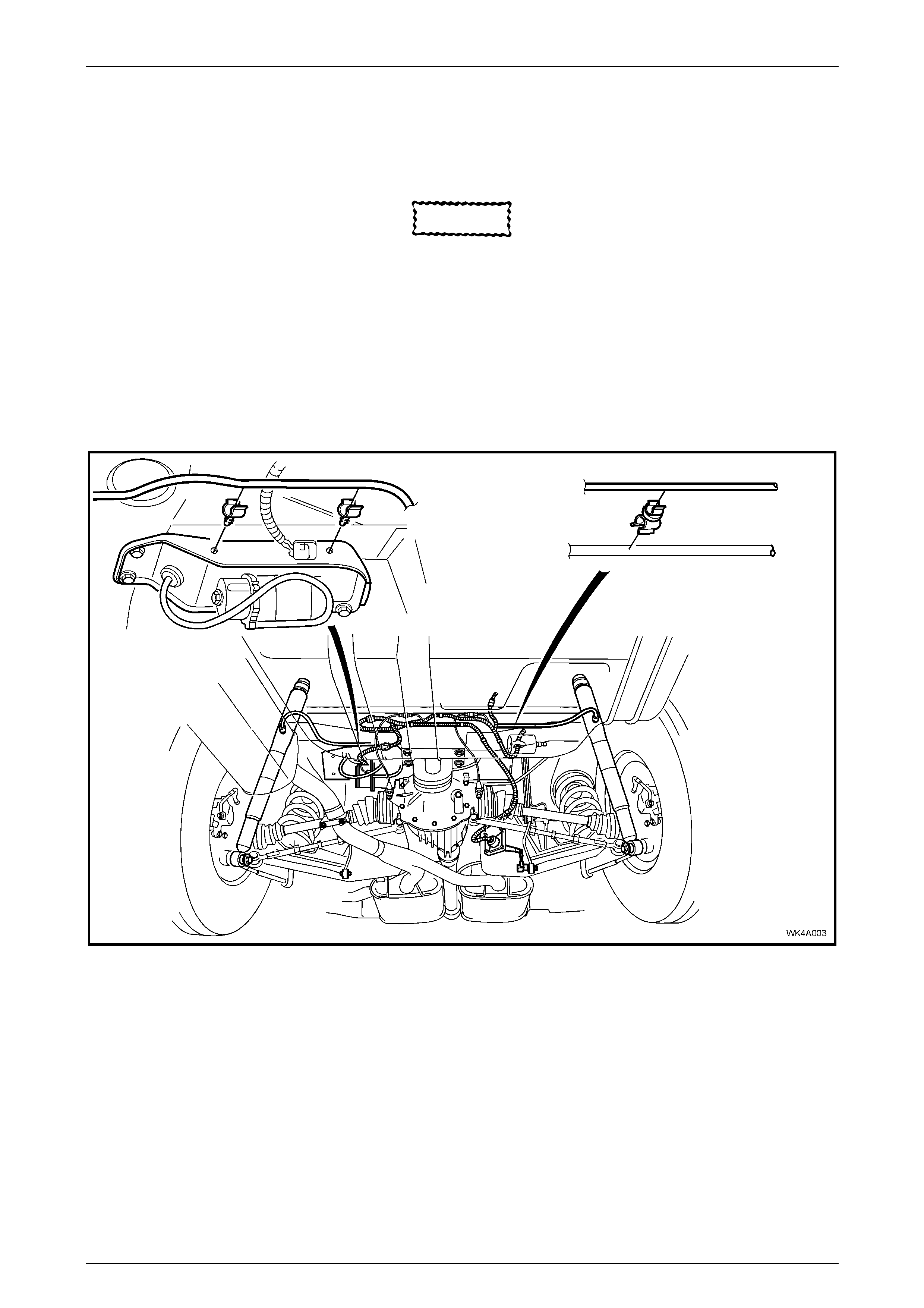
3.6 Air Lines
LT Section No. - 06-212
CAUTION
If air pressure in the level ride system is
lost during service procedures, do not lower
the vehicle until system pressure has
been restored, as damage will most likely
result. Charge the system as detailed in
3.2 Initial Air Charge in this Section.
The air lines are routed between the compressor and each shock absorber. Retaining clips are placed along each line to
secure the air line to the vehicle. Either screw-on type or clip-on type connectors are used to attach the air line to the
shock absorbers, and a clip-on T-piece attaches the air line to the compressor.
Figure 4A-12
Remove
1 De-pressurise the system. Refer to 3.4 Reli eving System Air Pre ssure in this Section.
2 Rotate the applicable connector 90 degrees, then carefully pull the connector and air line away from the
component.
Rear Suspension Page 4A-15
Page 4A–15
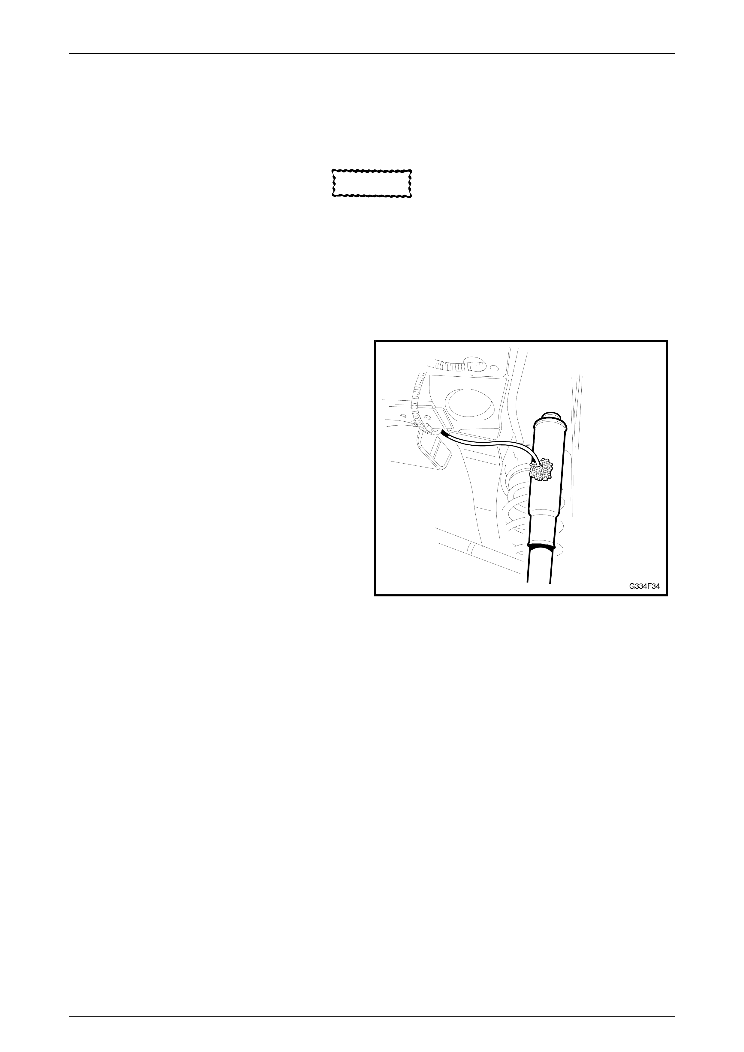
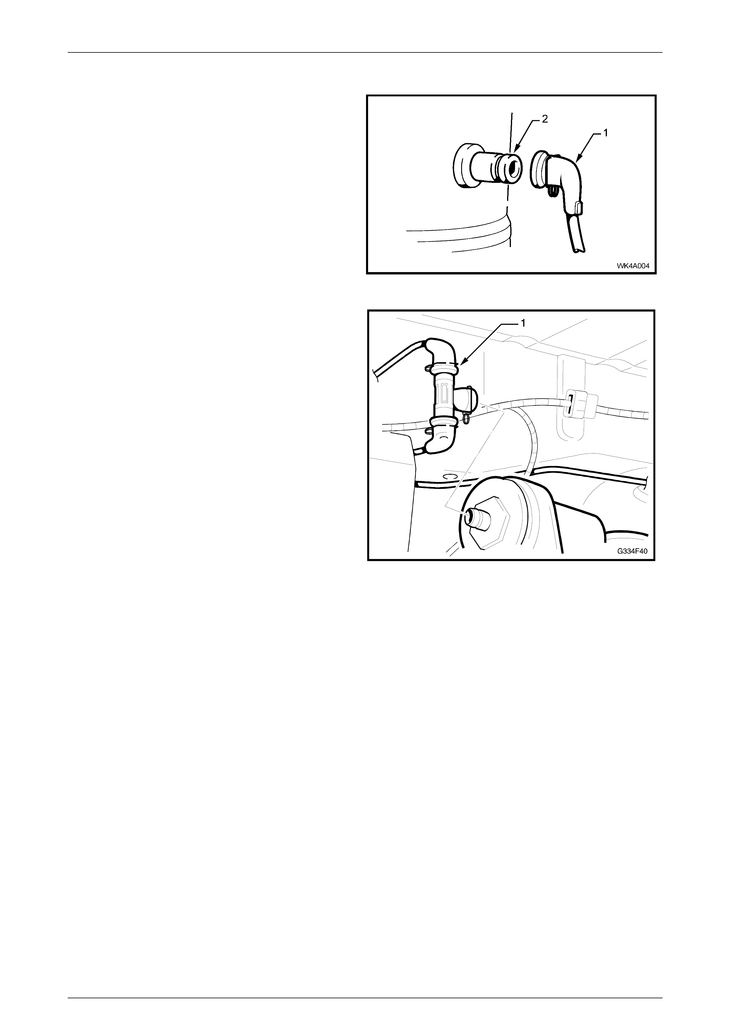
Reinstall
1 Route the airline in the retainers ensuring that there
are no kinks and it does not foul on the body or any
components.
2 Push the connection cap (1) onto the shock absorber
port (2) until the spring clip engages the groove in the
shock absorber fitt ing.
3 Charge the system with air and test for air leaks as
detailed in 3.2 Initial Air Charge and 3.3 Ai r Leak
Test, in this Section.
Figure 4A-13
4 Fit each air line connection onto the T-piece (1).
5 Push the T-piece onto the compressor fitting,
ensuring it is secure.
Figure 4A-14
Rear Suspension Page 4A-16
Page 4A–16
3.7 Level Ride Shock Absorber
LT Section No. - 06-212
Remove
CAUTION
If air pressure in the level ride system is
lost during service procedures, do not lower
the vehicle until system pressure has
been restored, as damage will most likely
result. Charge the system as detailed in
3.2 Initial Air Charge in this Section.
1 Raise the rear of the vehicle by placing a jack under the centre of the differential carrier, rais e the vehicle and place
safety stands under the trailing arms to support the weight of the vehi cle .
2 De-pressurise the system. Refer to 3.4 Reli eving System Air Pre ssure in this Section.
3 Disconnect the air line connection from the shock absorber. Refer to 3.6 Air Lines in this Section.
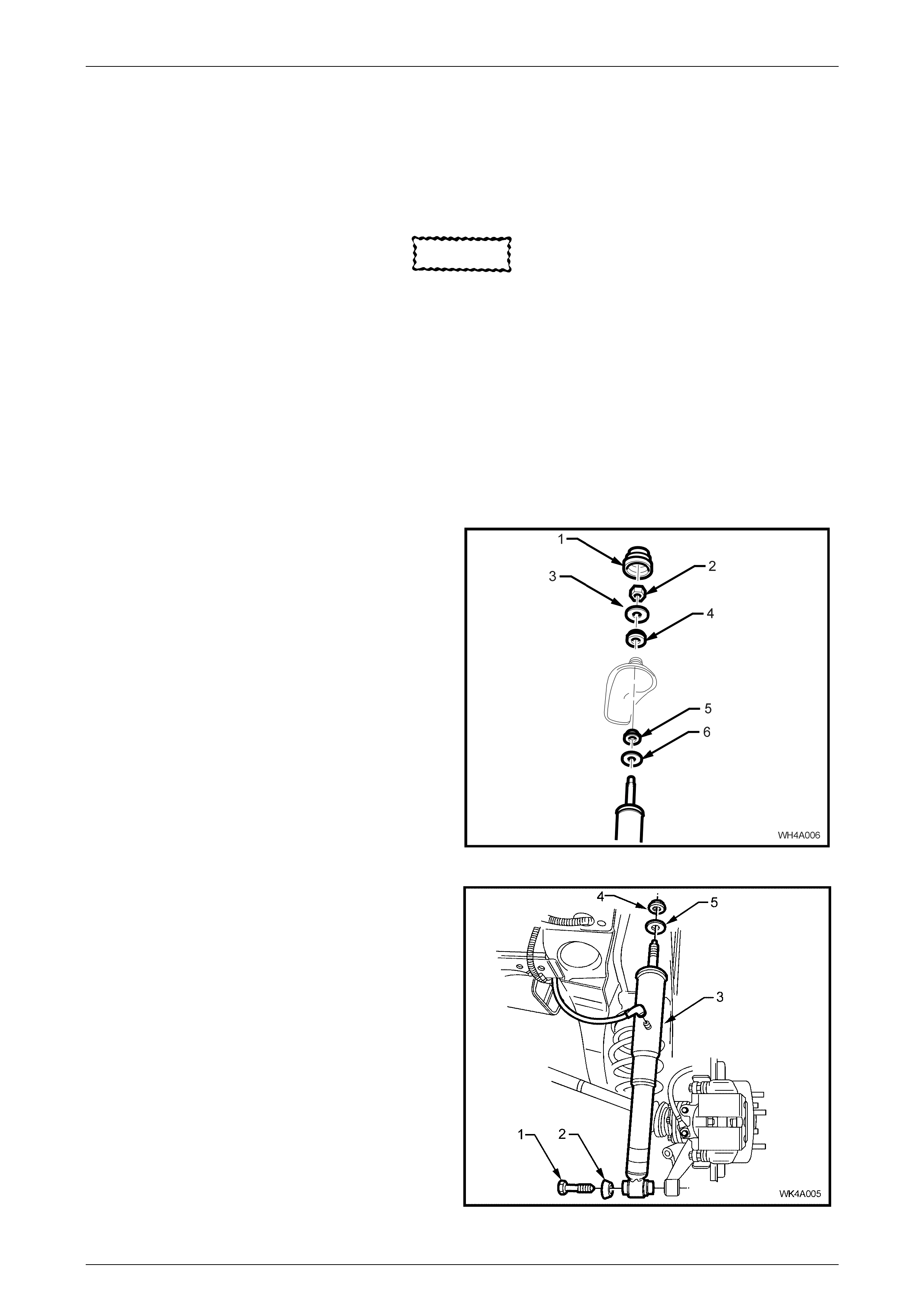
4 Open the rear compartment lid and prise off the shoc k
absorber upper mo unti ng cap cov er (1).
5 Remove the shock absorber upper mounting nut (2),
upper plate (3) and bush (4).
Figure 4A-15
6 Loosen and remove the lower shock absorber
mounting bolt (1) and washer (2) from the lower
mounting.
7 Lower the shock absorber (3) to clear the upper
mounting stud from the body, then remove the shock
absorber assembly from the vehicle.
8 Remove the upper mounting, lower bush (4) and
washer (5) from the shock absorber, as required.
Figure 4A-16

Rear Suspension Page 4A-17
Page 4A–17
Reinstall
1 The reinstalla tion procedure is the reverse of the removal proc edures except for the following:
2 With the upper mounting, lower bush (4) and washer (5) installed, position the shock absorber upper mounting stud
into the body aperture.
3 Install the upper mounting upper bush, upper plate and mounting nut.
4 Hand tighten the upper mounting nut until fully installed onto the threaded section of the shaft.
NOTE
Do not use power operated tools for this
operation, as thread damage will result.
5 Install the upper mounting cap cover.
6 Install the shock absorber lower mount into the trailing arm and install bolt and washer but do not fully tighten at
this stage.
NOTE
Ensure that the air line fitting on the shock
absorber is facing the rear of the vehicle.
7 Install the air line onto the shock absorber. Refer to 3.6 Air Lines in this Section.
8 Before lowering the vehicle to the ground, charge the system with air and test for air leaks as detailed in
3.2 Initial Air Charge and 3.3 Air Leak Test in this Section.
9 Lower the vehicle to the ground, then bounce the vehicle several times to settle the suspension.
10 Tighten the shock absorber lower mounting bolt to the correct torque specification.
! Shock absorber lower mount attaching
bolt torque specification............................ 105 – 125 Nm

Rear Suspension Page 4A-18
Page 4A–18
3.8 Ride Height Sensor
LT Section No. - 06-212
Remove
CAUTION
If air pressure in the level ride system is
lost during service procedures, do not lower
the vehicle until system pressure has
been restored, as damage will most likely
result. Charge the system as detailed in
3.2 Initial Air Charge in this Section.
NOTE
The position of the ride height sensor is critical to
the level ride system's operation. A bent or
damaged mounting bracket, connecting link or
ball stud plate, or incorrect installation of the
sensor and components can cause incorrect
operation.
1 Disconnect the battery, negative lead first.
2 Unclip or cut the cable ties securing the sensor wiring harness to the sensor bracket.
3 Disconnect the wiring harness connector (1) from the
sensor (2).
4 Disconnect the sens or link (3) from either the sensor
arm or ball stud plate (4).
5 While holding the sensor assembly, remove the
bolt (5) attaching the sensor mounting bracket (6) to
the crossmember.
6 Remove the sensor assembly.
7 If required, remove the nuts (7) attaching the sensor
to the mounting bracket.
8 If required, remove the bolt (8) attaching the ball stud
plate to the trailing arm.
Figure 4A-17
Rear Suspension Page 4A-19
Page 4A–19
Reinstall
Reinstallation of the ride height sensor is the reverse to removal procedures, ensuring to tighten all fasteners to the
correct torque specification.
Sensor bracket to crossmember
attaching bolt torque specification................15 – 30 Nm
Sensor to bracket attaching nut
torque specific atio n .................................... 3.0 – 8.0 Nm
" ! Stabiliser ba r link attaching bolt and nut
torque specification .................................... 95 – 105 Nm
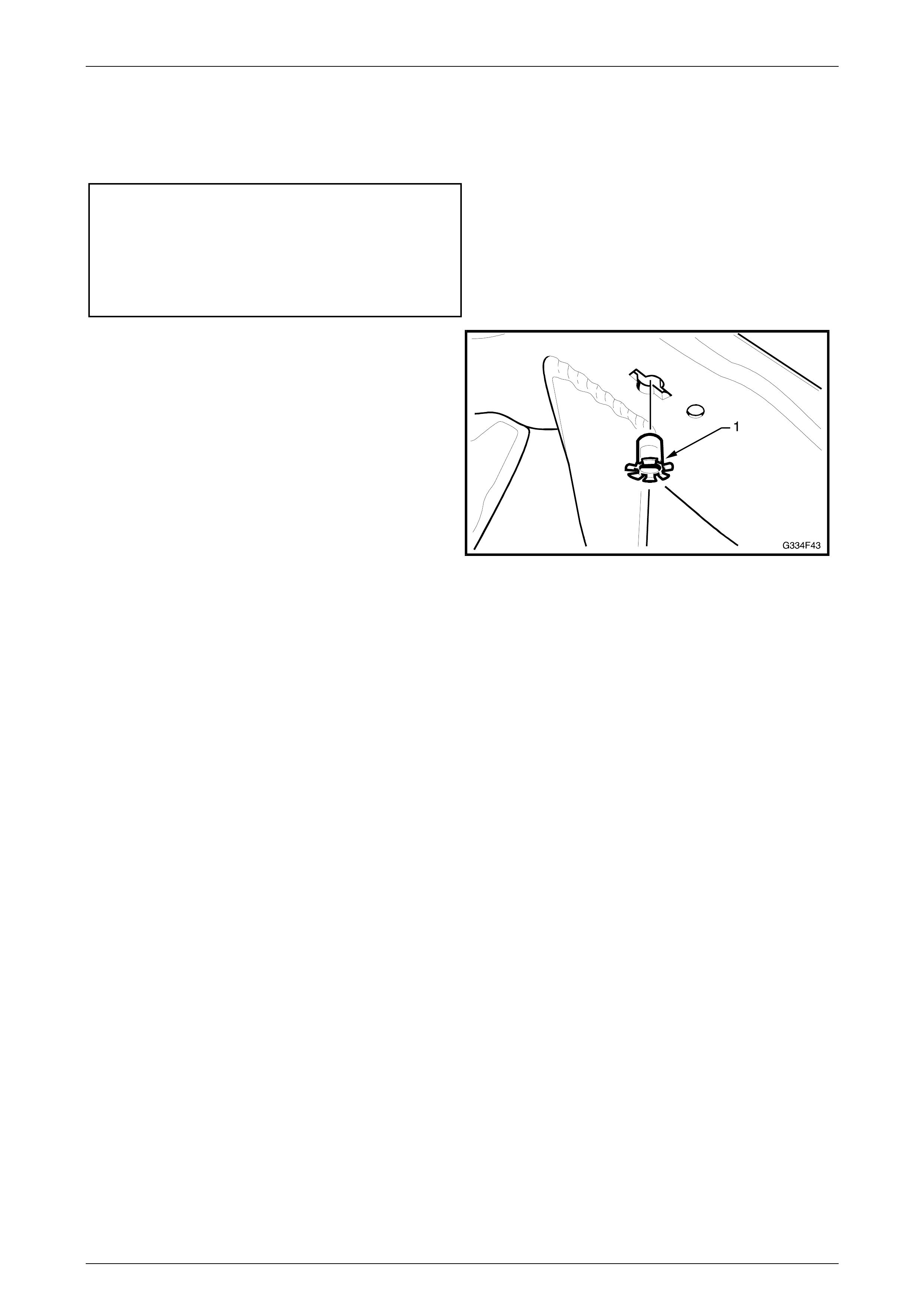
NOTE
If the rear suspension crossmember has been
replaced, insert the nut cage (1) into the
crossmember as shown.
Figure 4A-18
Rear Suspension Page 4A-20
Page 4A–20
4 Service Maintenance Operations -
Automatic Level Ride Suspension
CAUTION
If air pressure in the level ride system is
lost during service procedures, do not lower
the vehicle until system pressure has
been restored, as damage will most likely
result. Charge the system as detailed in
3.2 Initial Air Charge in this Section
The level ride system has been designed to be virtually maintenance free. Howeve r, at each scheduled service, the
following components must be inspected and rectified if found to be faulty.
Air Lines
Inspect the air lines for rubbing or fouling with the body and other components. Ensure the lines are not kinked and that
they are fitted into the retaining clips. Check the connections for correct fit.
Wiring Harness
Inspect the wiring harness for rubbing or fouling with the body and other components. Ensure that it is fitted and secured
into the retaining clips and/or cable ties. Check the connections for correct fit.
Air Filter
The compressor air filter (1) should be replac ed at the
scheduled service intervals set down in the Owner’s
Handbook. Inspect and replace more frequently if required,
where the vehicle is driven in dusty cond itio ns.
To service the compressor air filter, depress the two locking
tabs on the clip retaining the air intake hose (2) and filter to
the hole (3) in the compressor mounting bracket (4) and
withdraw the filter.
Test that the filter is clean and free from restrictions by
removing the filter form the tube and blowing through it from
the hose connection end. If any restriction is felt, replace
the filter.
Figure 4A-19
Rear Suspension Page 4A-21
Page 4A–21
5 Diagnosis - Automatic Level
Ride Suspension
The following procedures are designed to assist in the diagnosis of a fault in the level ride system. To achieve an
accurate diagnosis, the Technician must be familiar with the principles of operation of the system before proceeding.
The diagnosis tables contained in this Section are to be used in conjunction with the wiring schematic and wiring harness
diagrams, also provided.
Equipment
A digital multimeter with a minimum 10 Mega ohm impedance must be used when undertaking any electrical chec ks with
this system.
When performing tests on the wiring harness, use the appropriate probe adaptor to ensure the wiring and/or connectors
are not damaged during testing.
Ride Height Sensor Reset
If the compressor or exhaust solenoid operate for more than four and a half minutes, the sensor timers must be reset by
turning the ignition on, then off for 1 minute, then on again.
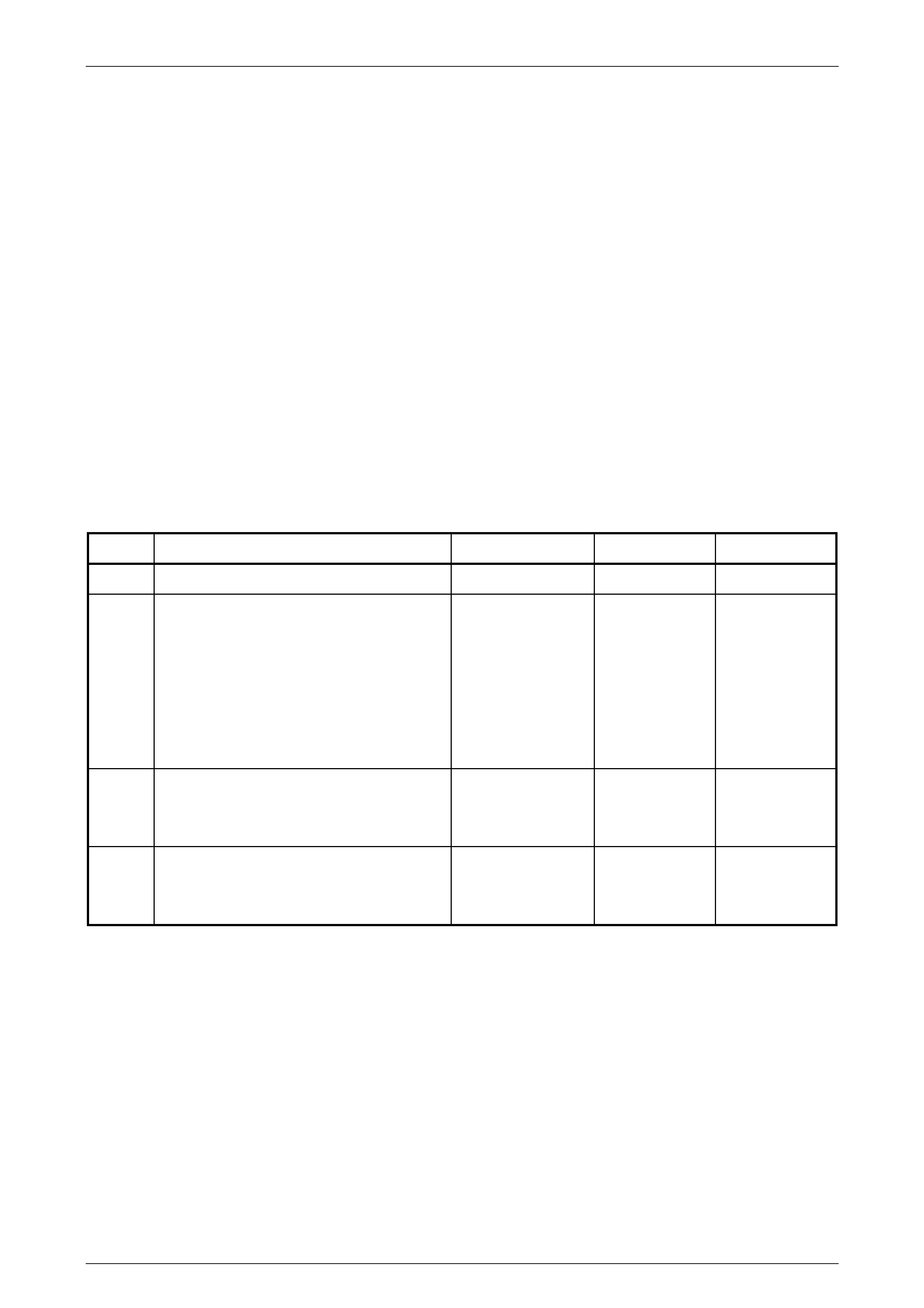
5.1 Preliminary Diagnostic Procedure
STEP ACTION VALUE YES NO
1 Does the vehicle trim? Go to Step 2. Go to Step 3.
2 Does the vehicle trim to the correct height? Refer to Sect ion 3,
4. Specifications in
this Service
Information.
System OK. Check all
suspension
components for
wear and
damage, paying
particular
attention to the
ride height
sensor mounting
and bracket.
3 Does the vehicle rise after the specified time
when the vehicle is loaded?
Place load in the vehicle.
20 seconds. Go to Step 4. Go to
5.2 Compressor
Assembly Test -
Motor.
4 Does the vehicle lower after the specified
time when the vehicle is unloaded.
Remove load from the vehicle.
20 seconds. System OK. Go to
5.3 Compressor
Assembly Test -
Solenoid.

Rear Suspension Page 4A-22
Page 4A–22
5.2 Compressor Assembly Test - Motor
STEP ACTION VALUE YES NO
1 Has a system reset been performed? Go to Step 2. Perform system
reset. Refer the
beginning of this
Section.
2 Is fuse F105 OK?
(Located in the engine compartment fuse
and relay panel assemb ly).
Go to Step 3. Replace blown
fuse. Check
wiring for the
ca use of the
blown fuse. Re-
check system.
3 Are fuses F38 and F15 OK?
(Located in the passenger compartment fuse
and relay panel assemb ly).
Go to Step 4. Replace blown
fuse(s). Check
wiring for the
ca use of the
blown fuse(s).
Re-check
system.
4 1 Disconnect the wiring harness at the
ride height sensor.
2 Turn the ignition on.
3 Bridge pin 3 (yellow wire) and pin 4
(black wire) in the ride height sensor
connector X1.
Listen for the compressor motor running, or
check for voltage between pins B (green
wire) and D (black wire) at the compressor
harness connec tor X 1.
Is the compressor motor running or the
voltage as specif ied?
Motor running, or
12 volts at the
compressor
harness con nec tor
X1 pins B (green
wire) and D.
Compressor
motor OK.
Proceed to
5.4, Ride Height
Sensor Test -
Compressor.
Go to Step 5.
5 Check the level ride wiring harness for
continuity.
Is the wiring ha rness continui ty OK?
Continuity. Replace the
compressor
assembly. Refer
3.5 Compressor
Assembly in this
Section.
Repair or
replace harness.

Rear Suspension Page 4A-23
Page 4A–23
5.3 Compressor Assembly Test - Solenoid
STEP ACTION VALUE YES NO
1 Has a system reset been performed? Go to Step 2. Perform system
reset. Refer the
beginning of this
Section.
2 Is fuse F102 OK?
(Located in the engine compartment fuse
and relay panel assemb ly).
Go to Step 3. Replace blown
fuse. Check
wiring for the
ca use of the
blown fuse. Re-
check system.
3 Are fuses F6 and F15 OK?
(Located in the passenger compartment fuse
and relay panel assemb ly).
Go to Step 4. Replace blown
fuse(s). Check
wiring for the
ca use of the
blown fuse(s).
Re-check
system.
4 1 Disconnect the wiring harness at the
ride height sensor connector X1.
2 Turn the ignition on.
3 Bridge pin 2 (white wire) and pin 4
(black wire) in the ride height sensor
connector X1.
Listen for a clicking of the solenoid valve and
air escaping from the system, or check for
voltage between pins A (white wire) and C
(orange/black wire) at the compressor
harness connec tor.
Are all conditions present or voltage as
specified?
Clicking sound from
the solenoid and air
escaping, or
12 volts at the
compressor
harness con nec tor
pins A and C.
Compressor
motor OK.
Proceed to
5.5, Ride Height
Sensor Test -
Solenoid.
Go to Step 5.
5 Check the level ride wiring harness for
continuity.
Is the wiring ha rness continui ty OK?
Continuity. Replace the
compressor
assembly.
Refer to
3.5 Compressor
Assembly -
Level Ride
Suspension in
this Section.
Repair or
replace harness.

Rear Suspension Page 4A-24
Page 4A–24
5.4 Ride Height Sensor Test - Compressor
STEP ACTION VALUE YES NO
1 Has a system reset been performed? Go to Step 2. Perform system
reset. Refer the
beginning of this
Section.
2 1 Disconnect the ride height sens or
connect ing lin k. Refer 3.8 Ride Height
Sensor - Level Ride Suspension in this
Section.
2 Turn the ignition on.
3 Raise the ride height sensor ar m 45
degrees and wait 20 seconds.
4 Listen for the compressor motor
running, or
Check for voltage between pins B
(green wire) and D (black wire) at the
compressor harn es s connector.
Does the compressor run or is the voltage as
specified?
Compressor motor
running, or
12 volts at
compressor
harness con nec tor
X1, pins B (green
wire) and D (black
wire).
Go to Step 3. Go to Step 6.
3 The compressor motor may be operating but
the compressor may have failed.
Run the motor for 2 minutes and check the
shock absorber air bag s are being
pressurised.
Is air pressure present in the shock absorber
air bags?
System OK.
Recheck sy stem
for correct
operation if
necessary.
Go to Step 4.
4 Check the air compressor filter for blockage.
Is the filter blocked?
Filter OK. Go to Step 5. Replace filter
and recheck the
system, refer to
4. Service
Maintenance
operations in
this Section.
5 Check the air lines for correct fitment, kinks
and damage.
Are all air lines OK?
Replace the
compressor
assembly and
recheck the
system. Refer to
3.5 Compressor
Assembly in this
Section.
Replace air line
and recheck the
system, refer to
4. Service
Maintenance
operations in
this Section.
6 Check ride height sensor wiring harness for
continuity.
Is the wiring ha rness continui ty OK?
Continuity. Replace the ride
height sensor
assembly. Refer
3.8 Ride Height
Sensor in this
Section.
Repair or
replace harness,
refer to
Section 12P,
Wiring Diagrams
in the MY 2003
VY and V2
Series Service
Information for
wiring repair
procedures.

Rear Suspension Page 4A-25
Page 4A–25
5.5 Ride Height Sensor Test - Solenoid
STEP ACTION VALUE YES NO
1 Has a system reset been performed? Go to Step 2. Perform system
reset. Refer the
beginning of this
Section.
2 1 Disconnect the ride height sens or
connect ing lin k. Refer 3.8 Ride Height
Sensor in this Section.
2 Turn the ignition on.
3 Lower the ride height sensor arm 45
degrees and wait 20 seconds.
4 Listen for clicking of the solenoid valve
and air escaping from the system, or
Check for voltage between pins A
(white wire) and C (orange/black wire)
at the compressor harness connector
X1.
Are all conditions present and voltage as
specified?
Clicking sound from
the solenoid and air
escaping, or
12 volts at the
compressor
harness connec tor
X1, pins A (white
wire) and C
(orange/black wire).
System OK.
Recheck sy stem
for correct
operation if
necessary.
Go to Step 3.
3 Check the ride height sensor wiring harness
for continuity.
Is the wiring ha rness continui ty OK?
Continuity. Replace the ride
height sensor
assembly. Refer
to 3.8 Ride
Height Sensor in
this Section.
Repair or
replace harness,
refer to
Section 12P,
Wiring Diagrams
in the MY 2003
VY and V2
Series Service
Information for
wiring repair
procedures.
Rear Suspension Page 4A-26
Page 4A–26
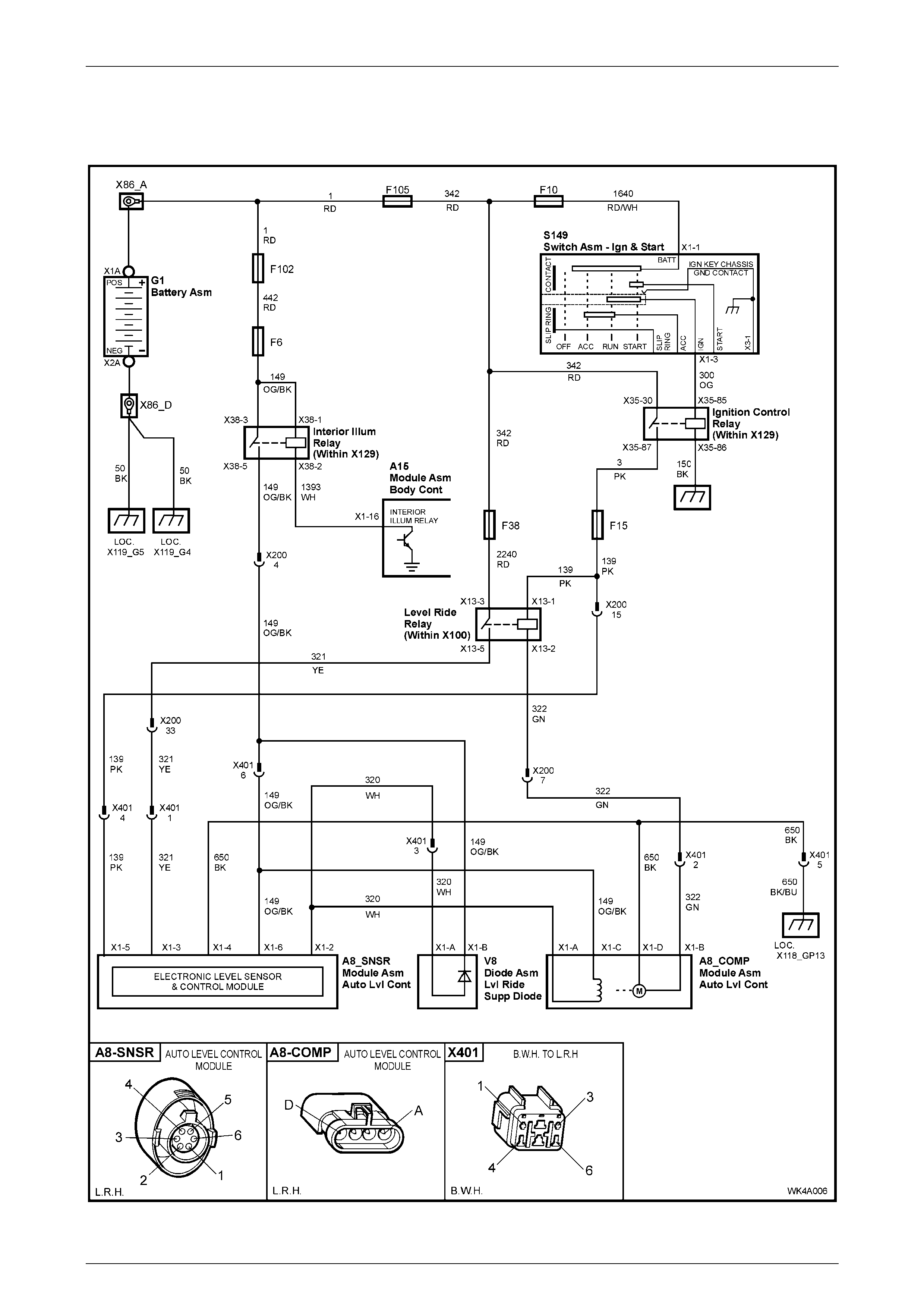
5.6 Wiring Diagram - Automatic Level Ride
Suspension
Figure 4A-20
Rear Suspension Page 4A-27
Page 4A–27
5.7 Wiring Harness Layout - Automatic Level
Ride Suspension
Figure 4A-21
Legend
1 Level Ride Compress or Wi ri ng Harness
2 Body Wiring Harness
3 Level Ride Wiring Harness
4 Level Ride Harness t o Body Harness Connec tor
5 Level Ride Harness t o Level Ride Sens or Connector
6 Level Ride Harness -to-Compressor Harness Connector
Rear Suspension Page 4A-28
Page 4A–28
6 Specifications
Front Suspension Details
SUSPENSION
CONFIGURATION COMPRESSION - 2/3 COMPRESSION
OF BUMPER (mm) REBOUND (mm)
LEVEL 1 to 4 & FE1 129 101
FE2 124 106
FX3 129 101
RHD LEVEL 5 & FE1 127 103
LHD LEVEL 5 & FE1 129 101
KL7 LPG 129 101
Rear Suspension Service Al i gnment Data
SUSPENSION
CONFIGURATION REAR
TRACK
(mm)
REAR WHEEL CAMBER
(VARIATION SIDE TO SIDE)
TOE DEGREES PER WHEEL
(VARIATION SIDE TO SIDE)
LEVEL 1, LPG & FE1 1587 -1°23' to -0°07'
(0°35' Maximum)
LEVEL 1 & FE2 1587 -1°41' to -0°25'
(0°35' Maximum)
LEVEL 1 & FX3 1587 -1°23' to -0°07'
(0°35' Maximum) +0°40' to +0°00'
(0°10' Maximum)
LEVEL 2 to 5 & FE1 1577 -1°23' to -0°07'
(0°35' Maximum)
LEVEL 2 to 5 & FE2 1577 -1°41' to -0°25'
(0°35' Maximum)
LEVEL 2 to 5 & FX3 1577 -1°23' to -0°07'
(0°35' Maximum)
Dimensions shown are for a vehicle at curb height, ie. vehicle ready to drive with all fluids at the recommended levels,
the fuel tank full and without driver, passenger/s or luggage.
Refer to Section 4A, 2.12 Rear Wheel Alignment Checking in the MY 2003 VY and V2 Series Service Information for
sp eci fic details.
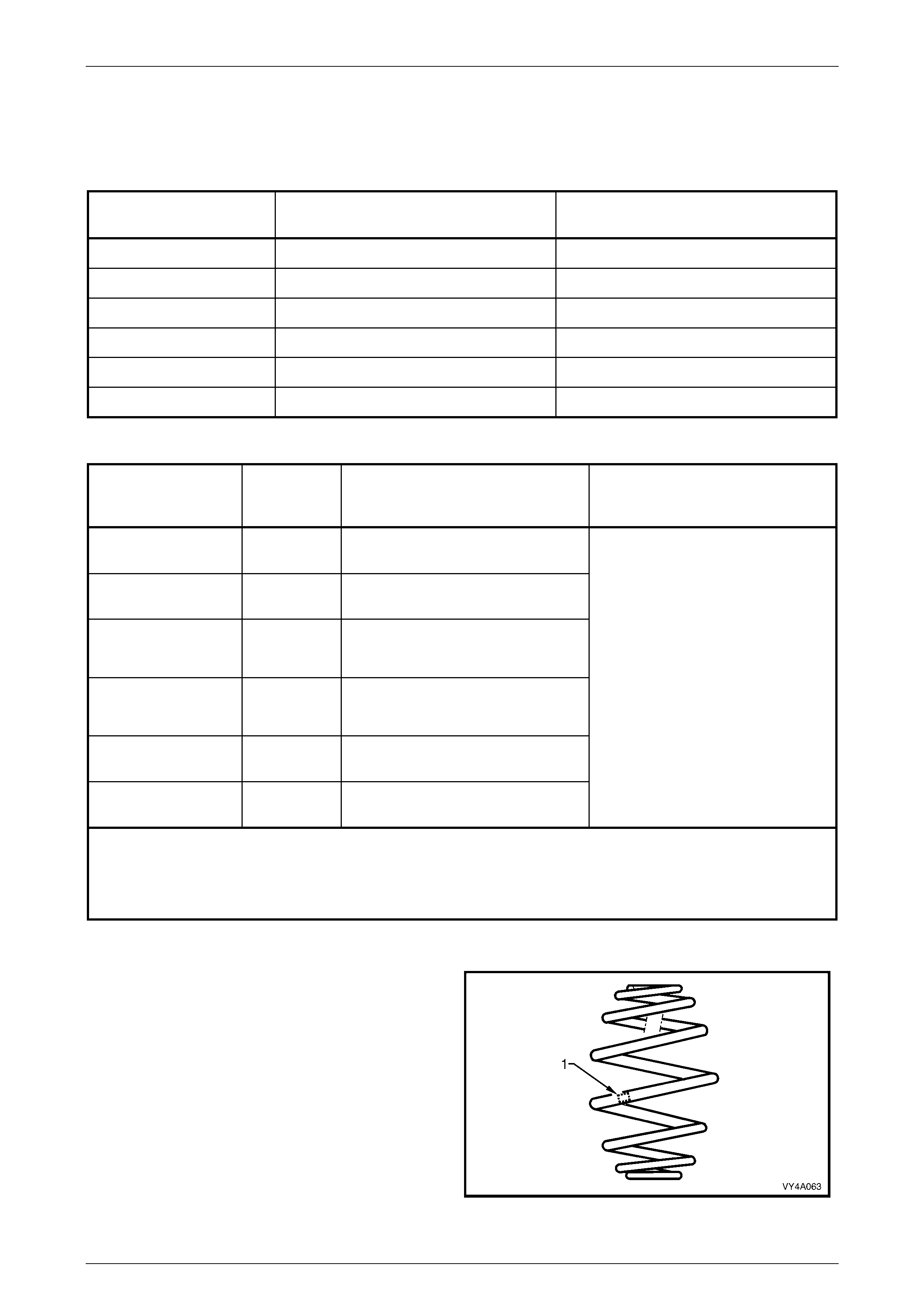
Rear Spring Details
Variable rate ‘Minibloc’ type rear springs are fitted to all MY
2004 WK Series vehicles. Identification of the rear spring
fitted to a particular vehicle can be achieved by cross-
referencing the two digit code, which is provided on the
production identification tag (1) with the table below.
Figure 4A-22
Rear Suspension Page 4A-29
Page 4A–29
SUSPENSION
CONFIGURATION NO. OF
COILS FREE
LENGTH
(mm)
OUTSIDE
DIAMETER
(mm)
SPRING TYPE AND RATE ID
CODE
RHD & FE1 7.8 284 158 Variable
40 N/mm - 71 N/mm
(5200 ± 180 N @ 156 mm)
EV
LHD & FE1 7.8 275 158 Variable
45 N/mm - 82 N/mm
(4400 N @ 177 mm)
EJ
FE2 7.5 250 158 Variable
51 N/mm - 90 N/mm
(4400 ± 150 N @ 168 mm)
EM
FX3 7.8 284 158 Variable
40 N/mm - 71 N/mm
(5200 N @ 156 mm)
EY
KL7 LPG 7.8 285 158
Variable
47 N/mm – 84 N/mm
(4400 N @ 188 mm)
EP
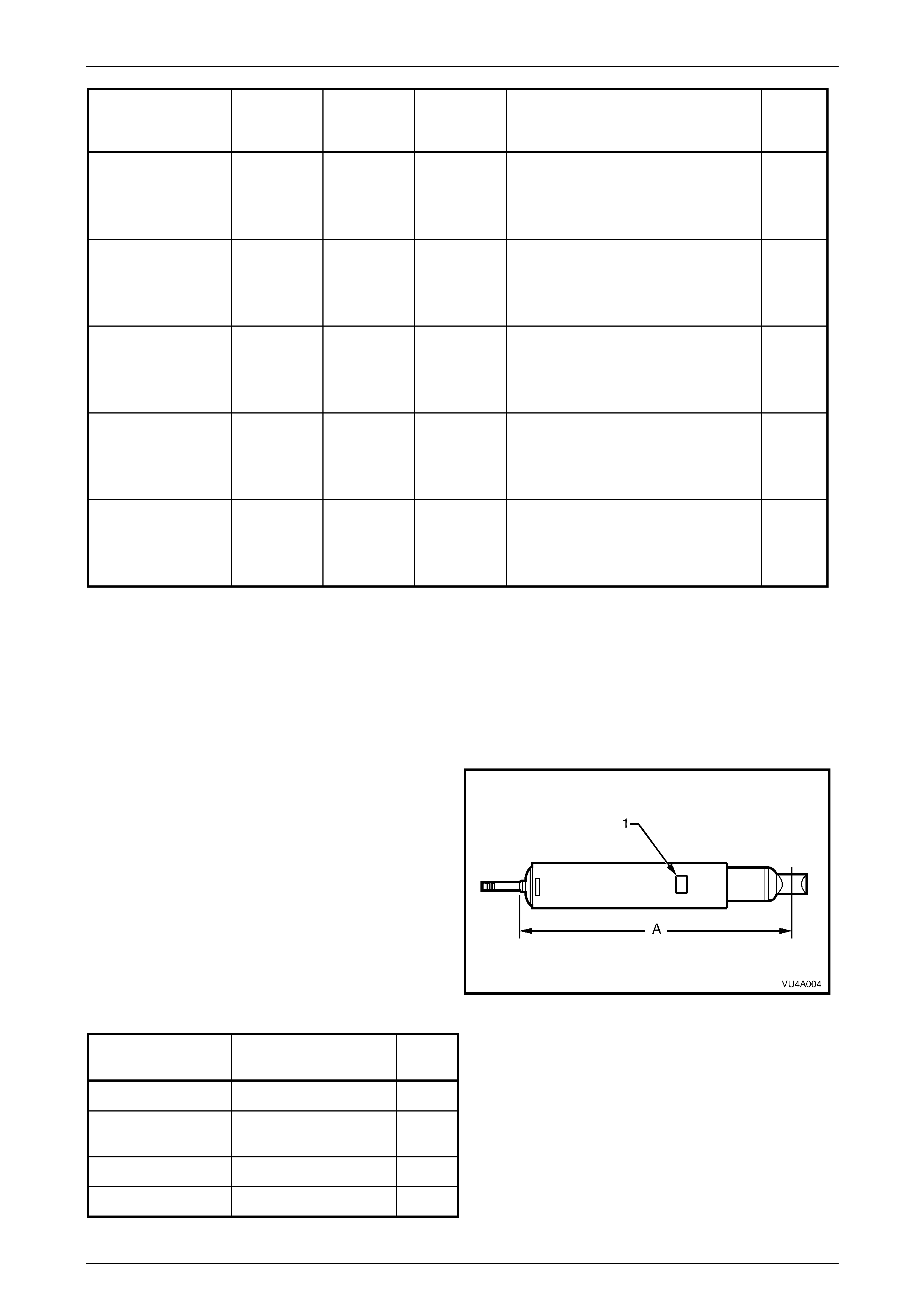
Rear Shock Absorber Details
The type of shock absorber fitted to a particular vehicle is dependent on the suspension option fitted to the vehicle as
follows:
FE1 and KL7 LPG (Standard Suspension) ................................................ Twin tube hydraulic
FE2 (Sports Suspension)............................................... Twin tube hydraulic, gas pressurised
FX3 (Auto Level Ride Suspension)....... Twin tube hydraulic, pneumatic adjustable (Superlift)
Identification of the rear shock absorber fitted to a particular
vehicle can be achieved by cross-referencing the two digit
code, which is provided on the production identification
tag (1) with the table below.
The table also provides nominal extended lengths (A).
Figure 4A-23
SUSPENSION
CONFIGURATION NOMINAL EXTENDED
LENGTH (mm) ID
CODE
RHD & FE1 670 MO
KL7 LPG, LHD &
FE1 670 TF
FE2 670 HJ
FX3 664 ME

Rear Suspension Page 4A-30
Page 4A–30
Rear Stabilizer Bar Details
Identification of the rear stabiliser bar fitted to a particular
vehicle can be achieved by cross-referencing the two digit
code, which is provided on the production identification
tag (1) with the table below.
The table also provides stabiliser bar diameter (2).
Figure 4A-24
SUSPENSION
CONFIGURATION DIAMETER
(mm) ID CODE
FE1 and LPG 13 FL
FE2 15 FJ
FX3 13 FL

Rear Suspension Page 4A-31
Page 4A–31
7 Torque Wrench Specifications
ATTENTION
!
!!
! Fasteners must be replaced after loosening.
"
""
" Vehicle must be at curb height before final tightening.
#
##
# Fasteners either have micro encapsulated sealant applied or incorporate a mechanical thread lock and
should only be re-used once. If in doubt, replacem ent is recommended.
Nm
Compressor to Mounting Bracket Bolt........................................................4 - 5
Compressor Mounting Bracket to Body Securing Sc rew ............................4 - 5
Ride Height Sensor to Mounting Bracket Nut .............................................3 - 8
Ride Height Sensor Bracket to Crossmember Bolt.................................15 - 30
" ! Stabiliser Bar Link Bolt and Nut....................................................95 - 105
Shock Absorber Upper Mounting Nut:.................Hand tighten to end of thread
! Shock Absorber Lower Mounting Bolt.............................................105 - 125
Rear Suspension Page 4A-32
Page 4A–32
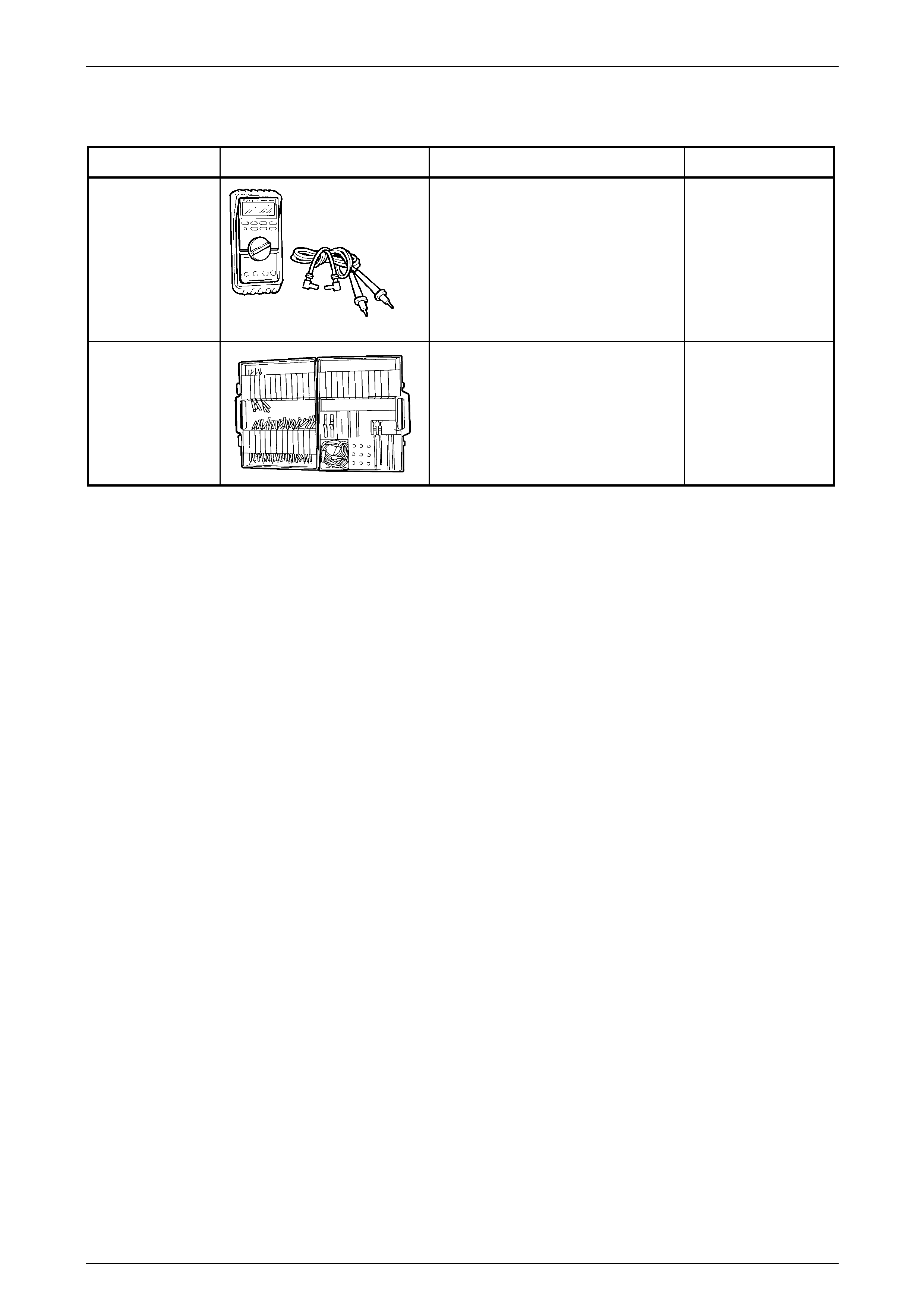
8 Special Tools
TOOL NUMBER ILLUSTRATION DESCRIPTION CLASSIFICATION
J 39200
DI G ITAL MU LTI-METER
Used when performing diagnosis of
auto level ride syste m.
Previously released.
Also commercially available, but must
have a 10 Mega ohm input
impedance.
Mandatory
KM-609
ELECTRONIC KIT
Used in conjunction with a multimeter
for measuring voltages and
resistances without damagi ng wiring
harnesse s conn ectors.
Previously released.
Mandatory